BLEINC. August 17, Black & Veatch Corporation 201 Brookfield Parkway, Suite 150 Greenville, SC 29607
|
|
|
- Olivia Floyd
- 6 years ago
- Views:
Transcription

 is pleased to present this report of geotechnical exploration for the proposed Renewable Water Resources (ReWa) Conveyance")
1 BLEINC. BUNNELL-LAMMONS ENGINEERING, INC. GEOTECHNICAL, ENVIRONMENTAL AND CONSTRUCTION MATERIALS CONSULTANTS August 17, 2017 Black & Veatch Corporation 201 Brookfield Parkway, Suite 150 Greenville, SC Attention: Subject: Mr. David Hart, P.E. Report of Geotechnical Exploration ReWa Conveyance Project Greenville, South Carolina BLE Project No. J Gentlemen: Bunnell-Lammons Engineering, Incorporated (BLE) is pleased to present this report of geotechnical exploration for the proposed Renewable Water Resources (ReWa) Conveyance Project in downtown Greenville, South Carolina. These services were provided generally as described in the Agreement Between Black & Veatch Corporation and Geotechnical Subconsultant Bunnell-Lammons Engineering, Inc. for the Downtown Greenville Conveyance. We appreciate the opportunity to offer our professional services on this project. If you have any questions or require additional assistance, please call. Sincerely, BUNNELL-LAMMONS ENGINEERING, INC. William A. Mathews, P.E. Chief Engineer Registered, SC James. C. Ernst Construction Services Manager 6004 PONDERS COURT PHONE (864) GREENVILLE, SOUTH CAROLINA FAX (864)
2 BLE TABLE OF CONTENTS AUTHORIZATION... 1 SCOPE OF EXPLORATION... 1 PROJECT INFORMATION... 1 FIELD EXPLORATION... 2 LABORATORY TESTING... 3 SITE GEOLOGY... 3 SUBSURFACE CONDITIONS... 4 JUNCTION BOX (CLEVELAND PARK)... 4 DIVERSION/SCREENING STRUCTURE... 4 DOGHOUSE VAULT DOGHOUSE VAULT DOWNSTREAM PIPELINE... 5 UPSTREAM PIPELINE... 6 GENERAL... 7 ANALYSIS AND DESIGN RECOMMENDATIONS... 7 VAULTS, JUNCTION BOX, DIVERSION STRUCTURE... 7 SETTLEMENT... 9 LATERAL EARTH PRESSURE... 9 DOWNSTREAM PIPELINE, UPSTREAM PIPELINE CONSTRUCTION RECOMMENDATIONS EXCAVATION CONDITIONS AND SLOPES Residual Soils Soft and/or Wet Soil Conditions Partially Weathered Rock and/or Rock Excavation CLEARING AND GRUBBING DEWATERING Vaults, Junction Box, Diversion Structure Pipeline ENGINEERED FILL SPECIFICATIONS REVIEW BASIS OF RECOMMENDATIONS... 18
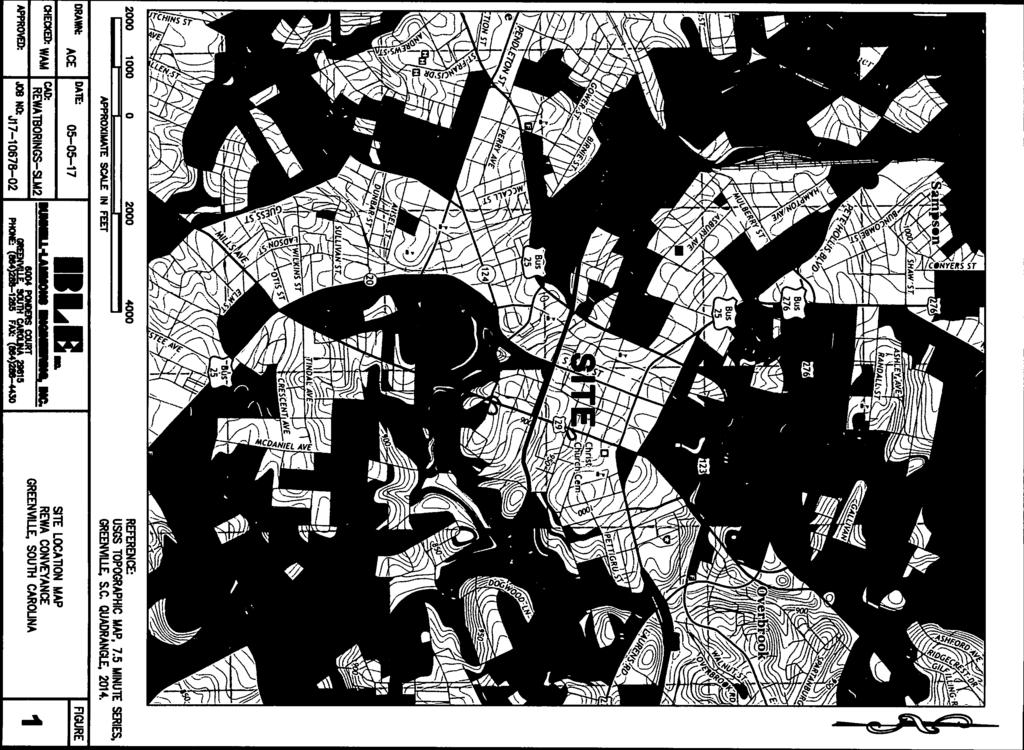
3 BLE APPENDIX SITE LOCATION MAP FIGURE 1 BORING LOCATION PLANS FIGURES 2 AND 3 LABORATORY TEST PROCEDURES LABORATORY TEST RESULTS FIELD EXPLORATION PROCEDURES FIELD RESISTIVITY TEST RESULTS BORING LOGS TUNNELMAN S GROUND CLASSIFICATION FOR SOILS KEY TO SOIL SYMBOLS AND CLASSIFICATION
4 BLE AUTHORIZATION A geotechnical exploration for the proposed ReWa Conveyance project was performed generally as described in the Agreement Between Black & Veatch Corporation and Geotechnical Subconsultant Bunnell-Lammons Engineering, Inc. for the Downtown Greenville Conveyance. SCOPE OF EXPLORATION This report details the findings of the geotechnical exploration performed for the proposed ReWa Conveyance project located in Greenville, South Carolina (reference Figure 1 in the Appendix). This report specifically addresses pipelines, structures, vaults, etc. that will be constructed using cut and cover techniques that are ancillary to the proposed tunnel. The tunnel is not addressed in this report. The intent of this exploration was to evaluate the subsurface soil and groundwater conditions at the site and provide detailed geotechnical recommendations for design of the foundations and associated project elements. We have also provided geotechnical related construction recommendations. PROJECT INFORMATION The following project information was provided in a request for proposal (RFP) from Mr. David Hart to our Mr. Bill Mathews. Included with the RFP was a site plan indicating the requested boring locations and Attachment A to Agreement for Professional Services, which included the requested scope of geotechnical exploration. Collectively, the ReWa Conveyance project consists of a new wastewater tunnel located generally along Broad Street and extending from Cleveland Park on the east end to South Hudson Street on the west end, a distance of approximately 6,000 feet. The tunnel will require a hard rock tunnel boring machine for construction. The project also includes upgrading and installing approximately 3,500 linear feet of gravity trunk sewer in the future Mayberry Park area, between Willard Street and South Hudson Street. The gravity trunk sewer will be installed using cut and cover techniques and will include trenching, pipe installation, pipe abandonment, pipe removal and connections to the existing sewer system. There are three geotechnical reports being prepared for the collective project as discussed below. 1. Mayberry Trunk Sewer: Report prepared by Bunnell-Lammons Engineering, Inc. (reference BLE Project No. J ) addressing trunk sewer construction located generally west of South Hudson Street. 2. ReWa Conveyance (this report): Report prepared by BLE (reference BLE Project No. J ) that addresses trunk sewer construction and associated structures located generally east of South Hudson Street.
5 BLE Report of Geotechnical Exploration August 17, 2017 ReWa Conveyance Project BLE Project No. J ReWa Reedy River Basin Sewer Tunnel: The Geotechnical Baseline Report (GBR) and Geotechnical Data Report (GDR) are being prepared by Black & Veatch. Geotechnical exploration required for the collective project included soil test borings (B-series borings), probe borings (P-series borings) and trunk sewer borings (TS-series borings). The B-series borings are located primarily along the tunnel alignment and included standard penetration testing in the soil. The B- series borings included rock coring. The P-series borings are located primarily along the tunnel alignment and included auger drilling (without sampling) to identify the top of rock. The TS-series borings are located primarily along the Mayberry Trunk Sewer alignment. The TS-series borings consisted of soil test borings with standard penetration testing. Refer to the GDR for boring logs not listed in this report. Subsurface data collected from some of each series of borings described above were utilized in developing the recommendations presented in this report. The following table summarizes the various structures associated with this report and the borings located near these structures. Structure Junction Box (Cleveland Park) Diversion/Screening Structure Grade Elevation Bearing Elevation Description Boring Foundation 21 by TS-9 and TS-9R (see note) Foundation 34 by 38 B-13 Doghouse Vault Foundation 16 by 18 P-24 Doghouse Vault Foundation 16 by 18 Between P-27 and P-29 Downstream Pipeline 840 to to Gravity Sewer B-22, TS-9 and TS-10 Upstream Pipeline 913 to to to 42 Gravity Sewer TS-11 to TS-16, B-10, P-1 and P- 19 to P-25 Note: Boring TS-9 was re-drilled as TS-9R to extend the boring to a greater depth. FIELD EXPLORATION The soil test borings represented by the B-series and TS-series borings included standard penetration test sampling (ASTM D 1586) and were drilled at the approximate locations shown on the attached Boring Location Plans (reference Figures 2 and 3 in the Appendix). The P-series borings consisted of auger drilling to the top of rock without sampling. 2
6 BLE Report of Geotechnical Exploration August 17, 2017 ReWa Conveyance Project BLE Project No. J The borings were located in the field by representatives of Black & Veatch and BLE. Boring elevations were provided by Black & Veatch. Boring Logs are presented in the Appendix of this report. At boring locations B-10, B-13, B-20, B-21 B-22, B-23, TS-2, TS-6 and TS-12, a piezometer was installed to permit long term groundwater level observations to be performed. Boring Logs and a separate Piezometer Installation Log are presented in the Appendix of this report. The boring locations shown in the Appendix are based on surveyed locations provided by Black & Veatch. A description of our field procedures is also included in the Appendix. In addition to the borings, we also conducted field resistivity testing between borings TS-1 and TS-2, TS-4 and TS-5, TS-12 and TS-13. A laboratory resistivity test was conducted on a composite soil sample collected from borings B-10, B-11 and B-22. The testing was performed in general accordance with ASTM G57. A brief description of the test procedures is presented in the Field Exploration Procedures section in the Appendix. The test results are also presented in the Appendix. LABORATORY TESTING Laboratory tests were conducted on assigned soil samples to evaluate classification and other engineering properties. The laboratory tests performed for this project include moisture content, grain size distribution and resistivity. A brief description of the laboratory test procedures is presented in the Appendix. The test results are also presented in the Appendix. SITE GEOLOGY The project site is located in the Piedmont Physiographic Province, an area underlain by ancient igneous and metamorphic rocks. The virgin soils encountered in this area are the residual product of in-place chemical weathering of the rock. In areas not altered by erosion, previous construction or other human activities, the typical residual soil profile consists of clayey soils near the surface where soil weathering is more advanced. The near surface clayey soils are typically underlain by sandy silts and silty sands. The boundary between soil and rock is not normally sharply defined. This transitional zone is termed partially weathered rock (PWR) and is normally found overlying the parent bedrock. For engineering purposes, partially weathered rock is defined as residual material with a standard penetration resistance of at least 100 blows per foot. Weathering is facilitated by fractures, joints, and the presence of less resistant rock types. As a result, the profile of the partially weathered rock and hard rock is quite irregular and erratic, even over short horizontal distances. Also, it is not unusual to find lenses and boulders of hard rock and zones of partially weathered rock within the soil mantle, well above the general bedrock level. 3
7 BLE Report of Geotechnical Exploration August 17, 2017 ReWa Conveyance Project BLE Project No. J The upper soils along drainage features and in flood plain areas are generally water-deposited (alluvial) materials that have been eroded and washed down from adjacent higher ground. Alluvial soils are usually soft and compressible, having never been consolidated by pressures in excess of their present overburden. The sewer alignment generally parallels and is contained (at least partially) within the floodplain of the Reedy River. Therefore, it should be anticipated that relatively loose/soft alluvial soils and shallow groundwater will be present along much of the alignment. Relatively loose/soft soils and shallow groundwater were encountered within the upper approximately 10 to 15 feet of the soil profile in the TS series borings. SUBSURFACE CONDITIONS Junction Box (Cleveland Park) The Junction Box will be constructed near boring TS-9/9R. Please note that boring TS-9 was re-drilled to a greater depth and noted as TS-9R. Borings TS-9 and TS-9R were drilled at essentially the same location. Subsurface conditions in this boring consisted of soft sandy silt fill extending to a depth of approximately 6 feet (elevation 836). The fill was underlain by apparent alluvial soils consisting of soft sandy clay and loose to very loose silty sand extending to a depth of approximately 28 feet (elevation 815). Residual soils consisting of firm silty sand were encountered at a depth of 28 feet (elevation 815). Groundwater was encountered at a depth of approximately 9.3 feet (elevation 833) at the time of drilling. Based on the subsurface conditions encountered in boring TS-9, the foundation for the Junction Box will bear in the loose silty sand at elevation feet. Diversion/Screening Structure The Diversion/Screening Structure will be constructed near boring B-13. Subsurface conditions in this boring consisted of very stiff sandy clay fill extending to a depth of approximately 2.5 feet (elevation 926). The fill was underlain by residual soils consisting of stiff sandy clay and firm silty sand extending to a depth of approximately 11.5 feet (elevation 917), at which depth auger refusal on hard rock (granitic gneiss) occurred. Rock coring was performed in this boring extending to a depth of feet (elevation 803). Groundwater was not encountered in this boring prior to auger refusal. Water used as part of the rock coring procedure prevents evaluating whether groundwater was encountered below auger refusal depth. Based on the subsurface conditions encountered in boring B-13, the foundation for the Diversion/Screening Structure will bear in hard rock at elevation
8 BLE Report of Geotechnical Exploration August 17, 2017 ReWa Conveyance Project BLE Project No. J Doghouse Vault 1 Doghouse Vault 1 will be constructed near probe boring P-24 and boring TS-15. Probe boring P-24 was drilled without sampling to evaluate the depth to rock. Auger refusal on hard rock occurred in this boring at a depth of approximately 21.5 feet (approximate elevation 898 feet). Boring TS-15 was drilled to a depth of 20 feet. Subsurface conditions in this boring consist of soft to stiff sandy clay extending to a depth of 4 feet (elevation 917) underlain by very loose to very dense silty sand extending to a depth of 20 feet (elevation 901). This vault will bear at a depth of approximately 12 feet (elevation 909), in the very loose sand encountered in boring TS-15 and well above the depth at which rock was encountered in P-24. Borings TS-13 and TS-14 were drilled approximately 90 to 100 feet west and east of the vault, respectively. At the planned bearing elevation of 909 feet, these borings encountered very loose silty sand (TS-13) and firm silty sand (TS-14). Stabilized groundwater levels in these borings were observed at approximately elevation 913 to 914 feet. Doghouse Vault 2 Doghouse Vault 2 will be constructed at boring TS-16. Boring TS-16 encountered auger refusal on rock at a depth of 7 feet (elevation 917 feet). This vault will bear at a depth of approximately 15 feet (elevation 909). Therefore, it should be anticipated that this vault will bear in hard rock. Downstream Pipeline Borings B-22, TS-9/9R, TS-10/10R, TS-10A are located near the Downstream Pipeline. Borings TS-9 and TS-10 were re-drilled to greater depth and referred to as TS-9R and TS-10R. Borings TS-9 and TS-9R were drilled at essentially the same location as were borings TS-10 and TS-10R. Subsurface conditions encountered in boring B-22 consisted of very stiff to stiff sandy silt and clayey silt extending to a depth of 6 feet (elevation 837). These soils were underlain by firm sandy silty clay and firm to very stiff clayey silt to a depth of 12 feet (elevation 831) and deeper loose silty sand extending to a depth of 13.5 feet (elevation 829). Auger refusal on hard rock (granitic gneiss) occurred at this depth. Rock coring was completed to a depth of 40 feet (elevation 803). Boring TS-9/9R encountered firm to very soft sandy silt and sandy clay extending to a depth of approximately 9 feet (elevation 833). These soils were underlain by loose to firm silty sand extending to a depth of at least 30 feet (elevation 812), at which depth the boring was terminated. Boring TS-10/10R encountered soft sandy silt and soft to very soft sandy clay extending to a depth of approximately 9 feet (elevation 832). These soils were underlain by very loose to loose silty sand extending to a depth of 5
9 BLE Report of Geotechnical Exploration August 17, 2017 ReWa Conveyance Project BLE Project No. J approximately 39 feet (elevation 802). Boring TS-10/10R encountered auger refusal at a depth of 39 feet (elevation 802). Groundwater was encountered in these borings at the time of drilling at depths ranging from approximately 8.7 feet to 9.3 feet (elevation 832). Boring TS-10A encountered firm to soft sandy silt and sandy clay extending to a depth of approximately 9 feet (elevation 835). These soils were underlain by very loose clayey and/or silty sand extending to a depth of approximately 19 feet (elevation 825). Auger refusal occurred in boring TS-10A at a depth of 19 feet (elevation 825). The bearing elevation of the downstream pipeline ranges from approximately elevation 823 to 824. Based on the borings referenced above, the downstream pipeline will bear in loose silty sand (TS-9/9R and TS- 10/10R) below the groundwater level or in hard rock (B-22 and TS-10A). Upstream Pipeline Soil test borings TS-11 through TS-16 and probe borings P-1 and P-19 through P-25 are located near the Upstream Pipeline. Borings TS-11 through TS-16 encountered soft to firm sandy silt and sandy clay extending to depths ranging from approximately 4 to 7 feet (elevation 913 to 921). These soils were underlain by very loose to loose silty sand extending to depths of at least 21.5 feet (elevation 897 to 900) in borings TS-11 and TS-12. Sampling was stopped at this depth in these two borings and auger probing continued to auger refusal on hard rock at depths ranging from 79 feet (elevation 842) in TS-11 to 71 feet (elevation 848) in TS-12. The very loose to loose silty sand extended to depths ranging from approximately 14 to 20 feet (elevation 898 to 910) in borings TS-13, TS-14 and TS-15. Boring TS-13 encountered very dense silty sand at a depth of 20 feet (elevation 898) and auger refusal on hard rock at a depth of 23.8 feet (elevation 894). Boring TS-14 encountered firm silty sand at a depth of 15 feet (elevation 910) and auger refusal on hard rock (granitic gneiss) at a depth of 17.7 feet (elevation 907). Rock coring was performed in this boring to a depth of 30.9 feet. Auger refusal occurred in boring TS-16 at a depth of approximately 7 feet (elevation 917) Groundwater was encountered in these borings one to four days after drilling at depths ranging from 3.2 feet to 11.8 feet (elevation 913 to 916). Probe borings P-1 and P-19 through P-25 encountered auger refusal on hard rock at depths ranging from 19.2 feet to 88.5 feet (elevation 834 to 903). The upstream pipeline will bear at elevation 911 to 913. Based on the above referenced borings, the upstream pipeline will bear in very loose to loose silty sand below the groundwater level or in hard rock (TS-16). 6
10 BLE Report of Geotechnical Exploration August 17, 2017 ReWa Conveyance Project BLE Project No. J General The above descriptions provide a general summary of the subsurface conditions encountered. The Boring Logs included in the Appendix contain detailed information recorded at each boring location. The Boring Logs represent our interpretation of the field logs based on engineering examination of the field samples. The lines designating the interfaces between various strata represent approximate boundaries and the transition between strata may be gradual. It should be noted that the soil conditions will vary between boring locations. It should be noted that groundwater levels may fluctuate several feet with seasonal and rainfall variations and with changes in the water level in adjacent drainage features. Normally, the highest groundwater levels occur in late winter and spring and the lowest levels occur in late summer and fall. The nearby Reedy River will have the most significant influence on groundwater levels for this project. ANALYSIS AND DESIGN RECOMMENDATIONS Presented below are design recommendations specific for each of the structures identified in the table presented in the Project Information section of this report. Additional recommendations applicable to the pipelines will follow. Vaults, Junction Box, Diversion Structure The Junction Box, Diversion/Screening Structure and Doghouse Vaults will be supported on spread footing foundations. Based on the boring data and our experience with similar soil conditions, much of the existing soils encountered in the borings at the design bearing elevations are suitable for spread footing foundation support of the proposed construction. Satisfactory performance of the shallow foundations is subject to the criteria and site preparation recommendations contained in this report. The following table summarizes the details for each of these structures and the recommended maximum foundation bearing pressures. Structure Junction Box (Cleveland Park) Diversion/Screening Structure Bearing Footing Applicable Net Allowable Elevation Dimensions Borings Bearing Pressure ft by ft TS-9 (note 2) 3 ksf ft by 38-ft B-13 5 ksf Doghouse Vault ft by 18-ft TS-15 2 ksf Doghouse Vault ft by 18-ft TS-16 5 ksf Notes: See following page 7 (note 3) (note 4) (note 5) (Note 1)
11 BLE Report of Geotechnical Exploration August 17, 2017 ReWa Conveyance Project BLE Project No. J In using net allowable bearing pressures, the weight of the foundation concrete below grade as well as the weight of the soil above the foundation may be neglected, assuming that the proposed finish grades are at or near existing grade. 2. At the proposed bearing elevation of 820.4, the junction box will bear near the top of the dense silty sand. Careful observation of the exposed bearing surface will be required to confirm that the very loose sands have been removed. Dewatering will be required. 3. The diversion/screening structure will bear in hard rock below the groundwater level. Considerably higher foundation bearing pressures may be possible if required. The recommended bearing pressure assumes that the foundation will bear on No. 57 stone used to level the bottom of the excavation and facilitate dewatering that will be required. 4. Boring TS-15 encountered very loose silty sand below the groundwater level at the planned bearing elevation of 909. It should be anticipated that some overexcavation may be required to get to suitable bearing conditions pending observations performed during construction. It should be expected that dewatering will be required. 5. Doghouse Vault 2 will bear in hard rock. Considerably higher foundation bearing pressures may be possible if required. The recommended bearing pressure assumes that the foundation will bear on No. 57 stone used to level the bottom of the excavation and facilitate dewatering that may be required. Exposure to the environment may weaken the soils at the foundation bearing level if the foundation excavations remain open for long periods of time. Therefore, we recommend that once each foundation excavation is extended to final grade, the foundation be constructed as soon as possible to minimize the potential damage to bearing soils. The foundation bearing area should be level or benched and free of loose soil, ponded water and debris. Foundation concrete should not be placed on soils that have been disturbed by seepage. If the bearing soils are softened by surface water intrusion or exposure, the softened soils must be removed from the foundation excavation bottom prior to placement of concrete. If the excavation must remain open overnight or if rainfall becomes imminent while the bearing soils are exposed, we recommend that a 2 to 4-inch thick "mud-mat" of "lean" (2,000 psi) concrete be placed on the bearing soils for protection before the placement of reinforcing steel. To verify that the soils encountered in foundation excavations are similar to those encountered in the soil test borings, we recommend that foundation excavations be examined. Part of this examination should include checking the bearing soils with a dynamic cone penetrometer performed by an experienced engineering technician working under the direction of the geotechnical engineer. Excavation support and dewatering will be required to maintain a safe excavation and permit construction of the structures. Additional discussion on dewatering and excavation support is presented in the Construction Recommendations section of this report. 8
12 BLE Report of Geotechnical Exploration August 17, 2017 ReWa Conveyance Project BLE Project No. J Settlement Settlement at each structure will be a function of the sustained loading applied to the foundation at each location as well as the net change in load on the foundation soils as a result of construction. Detailed structural loads have not been provided to permit settlement evaluation. However, we can offer the following considerations relative to settlement. Each of the structures are being built below grade and the corresponding weight of the volume of soil displaced at each location is expected to exceed that of the structure that replaces it. Based on preliminary estimates, the soil displaced by construction of the junction box weighs approximately two times that of the junction box. Therefore, the loads imposed on the foundation soils are expected to decrease as a result of the junction box construction. Conditions are expected to be similar at the other structure locations. As a result, there would not be any theoretical post construction settlement since the structural loads applied to the foundation soils will have decreased. Practically speaking, the relative effectiveness of dewatering and potential disturbance of the subgrade soils during construction may have more of an influence on post construction settlement of the structures. This is especially true for the junction box and the two doghouse vaults that will bear in soil. The contractor will have to protect the exposed subgrade soils to minimize disturbance during construction. The diversion/screening structure is expected to bear in hard rock and the resulting subgrade disturbance and post-construction settlement is expected to be negligible. Lateral Earth Pressure Below grade structures must be capable of resisting the lateral earth pressures that will be imposed on them. Walls which will be permitted to rotate at the top, such as cantilever retaining walls, may be designed to resist the active earth pressure. The active earth pressure coefficient is designated as Ka. Typically, a top rotation of about 1 inch per 10 feet height of wall is sufficient to develop active pressure conditions in soils similar to those encountered at the site. We recommend a Ka value of 0.36 for the soils encountered at this site when placed in accordance with the requirements for engineered fill. Walls which will be prevented from rotating, such as those associated with the underground structures for this project, should be designed to resist the at-rest lateral earth pressure. The at-rest earth pressure coefficient is designated as Ko. We recommend a Ko value of 0.53 for the soils encountered at this site when placed in accordance with the requirements for engineered fill. The passive earth pressure may be considered as the pressure exerted on the side of a foundation which aids in resisting sliding of the foundation. The passive earth pressure coefficient is designated as Kp. Friction 9
13 BLE Report of Geotechnical Exploration August 17, 2017 ReWa Conveyance Project BLE Project No. J resistance along the base of the foundation may also be used to resist sliding. The coefficient of frictional resistance is designated as fs. We recommend a fs value of 0.4 and a Kp value of 2.77 for the soils encountered at this site. Consideration should be given to dividing the passive earth pressure coefficient by a safety factor of 2 to limit the amount of lateral deformation required to mobilize the passive resistance. Published documentation 1 indicates that very little horizontal compression (approximately 0.5% relative to wall height) is required to develop one-half of the available passive resistance, hence the suggested safety factor of 2. However, depending on soil type and relative density it may take 2 to 15% horizontal compression to develop the full passive resistance. The values presented above assume that the ground surface is level. Sloping backfill (or sloping soil surfaces in front of a footing when considering passive resistance) will dramatically influence the earth pressure coefficients. Bunnell-Lammons Engineering should be consulted concerning applicable earth pressure coefficients where sloping soil surfaces may be present. The compacted mass unit weight of the backfill soil, which we estimate to be approximately 125 pcf, should be used with the earth pressure coefficients to calculate lateral earth pressures. Lateral pressure arising from surcharge loading, earthquake loading, and groundwater should be added to the above soil earth pressures to determine the total lateral pressures which the walls must resist. Where practical, we recommend that retaining walls and other below grade walls incorporate filtered gravity drainage systems to prevent the buildup of excess hydrostatic pressures behind the walls. In addition, transient loads imposed on the walls by construction equipment during backfilling should be taken into consideration during design and construction. Excessively heavy grading equipment should not be allowed within about 5 feet horizontally of the walls. Downstream Pipeline, Upstream Pipeline It is expected the Downstream and Upstream Pipelines will be constructed by open cut excavation. The following table provides a summary of the planned open cut pipeline construction. 1 Soil Mechanics by T. William Lambe and Robert V. Whitman; Massachusetts Institute of Technology; 1969; p
14 BLE Report of Geotechnical Exploration August 17, 2017 ReWa Conveyance Project BLE Project No. J Structure Downstream Pipeline 60-inch gravity sewer Upstream Pipeline 36-inch and 42-inch gravity sewer Existing Site Grade Elevation Planned Bearing Elevation Depth of Cut (feet) Likely Bearing Conditions 840 to to to 22 Very loose to firm silty sand (TS- 9/9R and TS-10/10R) below the groundwater level or in hard rock (B-22 and TS-10A) 913 to to 913 negligible to 19 Very loose to loose silty sand below the groundwater level or in hard rock (TS-16) Each of the pipelines will be installed below the groundwater level. Therefore, the contractor should anticipate that extensive dewatering will be required to install these lines. Additionally, the Upstream Pipeline and portions of the Downstream Pipeline will bear in relatively loose/soft soils. For pipes bearing in these conditions, it should be anticipated that a minimum 2 feet of stone embedment will be required to stabilize the base of the excavation. Excavations below the groundwater level will require trench boxes, shoring, sheeting or some other form of bracing to provide excavation safety. Additional recommendations are presented in the Construction Recommendations section of this report. CONSTRUCTION RECOMMENDATIONS Excavation Conditions and Slopes Confined excavations such as for utility installation or below-grade wall construction should conform to OSHA regulations. Excavation slopes along the alignment will encounter a variety of subsurface conditions and, as a result, the contractor should be prepared to encounter conditions ranging from soft, wet alluvial soils to dry residual soils and partially weathered rock or rock. Excavation conditions can generally be divided into three categories based on the subsurface conditions encountered. These categories and a corresponding discussion are presented below. Please note that a competent person as defined by OSHA regulations must verify the excavation conditions in the field at the time of construction. It should also be noted that in the presence of groundwater, it may be necessary to incorporate sheeting, shoring, bracing or some other form of excavation support to maintain a safe, stable excavation. We recommend that the contractors be required to submit an engineered plan for dewatering 11
15 BLE Report of Geotechnical Exploration August 17, 2017 ReWa Conveyance Project BLE Project No. J and excavation safety, particularly for the structure locations where excavations will be open for an extended period of time. Residual Soils As evidenced by the subsurface conditions encountered in the borings, some of the required excavation can be completed using conventional equipment and procedures. In these limited areas of the alignment, the required excavation will occur in residual soils without encountering rock or groundwater. These soils would be classified as Type B in accordance with the OSHA regulations which would permit an excavation side slope of 1:1 (horizontal:vertical). Soft and/or Wet Soil Conditions The ReWa Conveyance project is located along the Reedy River and much of the construction will require excavation in alluvial soils below the groundwater level. The soils encountered in these areas should be expected to be relatively loose and/or soft soils. These relatively loose/soft soils are prone to be unstable in relatively steep-sided excavations, particularly in the presence of a high groundwater table. These soils would be classified as Type C in accordance with OSHA regulations which would permit an excavation side slope of 1½:1 (horizontal:vertical). Please note that in the presence of high groundwater, these soils may require a flatter side slope excavation, trench shields, shoring or bracing to maintain excavation stability. Based on Tunnelman s Ground Classification for Soils (included in Appendix), it is expected that these soils may exhibit raveling, running or flowing behavior. Partially Weathered Rock and/or Rock Excavation Partially weathered rock or rock (as inferred by auger refusal or material that was cored) was encountered at some locations. It is expected that 10 to 12 feet of hard rock excavation will be required for construction of the Diversion/Screening Structure (B-13). Coring of the rock in this zone resulted in recovery ranging from 58% to 94% and Rock Quality Designation (RQD) ranging from 15% to 94%. Based on the RQD, the rock mass quality within the anticipated depth of excavation for the Diversion/Screening Structure ranges from very poor to excellent, improving with depth. While it may be possible to remove the partially weathered and relatively poor quality rock with hydraulic or pneumatic hammers, it is often extremely difficult to do in confined excavations. The good to excellent quality rock will require blasting for removal. There may be partially weathered rock or rock encountered in other areas as well. As stated previously, there is usually no sharp distinction between soil and rock in residual soil areas such as may be encountered at this site. Typically, the degree of weathering simply decreases with increasing depth until sound rock is eventually 12
16 BLE Report of Geotechnical Exploration August 17, 2017 ReWa Conveyance Project BLE Project No. J reached. The partially weathered rock, as well as the soil above, may also contain boulders, lenses, or ledges of hard rock. Some of the partially weathered rock of the transitional zone could be penetrated by the mechanical auger used in this exploration and can sometimes be excavated without blasting (i.e. hydraulic or pneumatic hammers). However, it is often extremely difficult to excavate partially weathered rock without blasting, especially in confined excavations such as utility trenches and footings. The ease of excavation depends on the quality of grading equipment, skill of the equipment operators, and geologic structure of the material itself such as the direction of bedding, planes of weakness, and spacing between discontinuities. Rock that cannot be penetrated by the mechanical auger will normally require blasting to loosen it for removal. Material that cannot be excavated will require blasting for efficient removal. The contractor should determine the combination of hole spacing and charge weights per delay to break the rock acceptably for excavation without damaging the existing water main or other nearby structures. Also of critical importance will be the requirement to excavate the rock mass to the horizontal and vertical dimensions shown on the plans and specifications. Controlled blasting techniques (pre-splitting or line drilling of closely spaced holes) could possibly be used to avoid unacceptable damage to rock that is to remain in-place. The geologic structure of the rock may preclude achieving horizontal breakage at the desired depth in the excavation. The contractor will have to determine by experience and experimentation as to how deep to drill below the intended excavation bottom so that the high points on the surface of the resulting unbroken rock remain below the desired bottom of excavation. Generally, the depth of such required "subdrilling" is one to three feet, depending on the spacing of the holes. For assistance in design of the initial construction blasts, and subject to confirmation by vibration monitoring during construction, peak particle velocities at critical structures or locations could be estimated using published relations of charge weight per delay and distance. If requested, BLE could perform construction vibration monitoring during blasting operations to assist in developing attenuation curves for the site. The blasting contractor could then use the attenuation curves to adjust the charge weight per delay to keep vibrations within desired limits. Presented in the following tables are recommendations for peak particle velocity based on various types of construction. The blasting contractor should strive to keep the peak particle velocities at or below these levels for the respective types of construction that could be affected by the blasting operations. 13
17 BLE Report of Geotechnical Exploration August 17, 2017 ReWa Conveyance Project BLE Project No. J Typical Allowable Peak Particle Velocity Criteria Relating to Damage to Residential Structures 2 Peak Particle Velocity (v) Potential Building Damage (inches per second) 0.50 Plaster on lath interiors subject to low-frequency (<40 Hz) blast vibrations Modern gypsum board (drywall) construction subject to low-frequency (<40 Hz) blast vibrations. 2 Caution value to avoid cosmetic damage to residential construction subject to high frequency (>40 Hz) blast vibrations. Age of Concrete in Hours Peak Particle Velocity Criteria Relating to Curing Concrete 3 Peak Particle Velocity (inches/second) Greater than 24 7 Prior to permitting blasting, specific limitations on blasting times and maximum vibration tolerances should be finalized. We recommend that the owners and occupants of nearby structures be contacted prior to blasting and alerted to the fact that they will hear noise that may be startling but does not indicate harm to them or their property. Pre-construction crack surveys should be performed on nearby structures so that alleged changes in cracks or the appearance of new cracks can be confirmed. Pre-construction observation may indicate detailed surveys and/or monitoring may be prudent for other structures constructed of vibration sensitive materials further from the area of blasting. The use of blasting mats and appropriate soil cover to control "flyrock" and noise is recommended. Rock that is thrown could damage adjacent property and would pose a substantial risk to people and property in the vicinity. It has been our experience in this area that temporary excavation slopes in partially weathered rock should be laid back at approximately ½:1 (horizontal:vertical). In unweathered rock the excavation can be 2 Structure Response and Damage Produced by Ground Vibration from Surface Mine Blasting; Bureau of Mines Report of Investigations; 1980; p Concrete Construction; February 1985; p
18 BLE Report of Geotechnical Exploration August 17, 2017 ReWa Conveyance Project BLE Project No. J approximately ¼:1 (horizontal:vertical). The actual allowable slope will depend on several factors including whether groundwater is present, the frequency and inclination of fracture planes (whether naturally occurring or due to blasting) and whether there are soil seams present in the rock mass. The slope recommendations for partially weathered rock or rock are consistent with Type A soils or Stable Rock as indicated in the OSHA regulations. Clearing and Grubbing All existing topsoil, vegetation, disturbed soils, limbs, stumps and surface soils containing organic matter or other deleterious materials should be segregated from the clean soil excavation. These deleterious and/or organic materials should not be used as general backfill around the pipe or structures. However, topsoil and organic soils may be used within the upper foot in areas to be reseeded. Dewatering Vaults, Junction Box, Diversion Structure The vaults, junction box and diversion structure will require dewatering to permit construction. At some locations, wellpoints may be required for efficient dewatering. We recommend that the groundwater table be lowered and maintained at a depth of at least 2 feet below bearing levels and excavation bottoms during construction. In addition to wellpoints, it may also be necessary to overexcavate approximately one to two feet below the planned bearing elevations of the foundations and backfill to the design bearing elevation with No. 57 stone. If the excavation terminates in soil, the excavation should be lined with a non-woven filter fabric (such as Mirafi 140N or similar) and backfilled to the design bearing elevation with No. 57 stone. If the excavation terminates in rock, the filter fabric will not be required. The stone would provide a drainage layer and a stable work surface. The excavation should be gradually sloped to a filtered sump where a temporary pump could be used to keep the water levels down during construction. Once construction has proceeded to the point that uplift due to buoyancy is not a concern, the pump could be removed. Predominantly sand alluvial and residual soils encountered within the expected depths of excavation will require excavation support to complete the excavation. We do not consider that sloping the foundation excavations will be a viable alternative for excavation safety below the groundwater level. As mentioned previously, the contractor should be required to have an engineered plan addressing site dewatering and excavation shoring and bracing for the structures at this site. 15
19 BLE Report of Geotechnical Exploration August 17, 2017 ReWa Conveyance Project BLE Project No. J Management of surface water could likely be accomplished by means of gravity ditches and pumping from gravel-lined, cased sumps. Soil berms, hay bales or similar methods should be employed to prevent surface water from running into the excavations. Pipeline Dewatering along the various pipeline alignments will be required during construction. The dewatering will likely need to occur by the installation of a wellpoint system and/or by dewatering from within the excavation. If wellpoints are used, we recommend an engineered system by a specialty dewatering contractor. Where dewatering occurs by pumping from within the pipeline excavation, we recommend that the relatively soft/loose alluvial soils be overexcavated a minimum of two feet below the design bottom excavation. If very soft soils are present at this depth, it may be necessary to extend the overexcavation deeper. The overexcavation should be backfilled to the design bottom of the excavation with a coarse graded stone such as ASTM designation No. 57 stone. Temporary cased sumps should be installed within the stone layer to permit dewatering ahead of the pipe installation. In this fashion it should be possible to adequately dewater the excavation to permit installation of the pipe on a firm subgrade. The pumping should be maintained continuously until the excavation is backfilled to sufficient depth to resist the effects of buoyancy. If dewatering is discontinued too soon, it may not be possible to maintain the pipeline at the specified slope. Engineered Fill The following recommendations for engineered fill placement apply to structural areas that will be disturbed during the course of construction, such as open cut excavations across existing roads, driveways, etc. Although placing and compacting the backfill soils in accordance with the requirements for engineered fill will minimize future settlement, it is not considered essential where the pipelines cross undeveloped areas. Engineered fill should be uniformly compacted in approximately 6 to 8-inch loose lifts to at least 95 percent of the standard Proctor maximum dry density (ASTM D 698). In addition, at least the upper 24 inches of subgrade fill beneath pavement should be compacted to at least 98 percent of the maximum dry density. The moisture content of the fill soils at the time of compaction should be within three percent of the optimum moisture content as determine by ASTM D 698. Based on our visual examination, laboratory testing and experience with similar soil types, the on-site soil appears to be suitable for use as engineered fill with proper moisture adjustment. In general, soils having a Plasticity Index (PI) greater than 25 should not be used for fill. We also recommend that soils used as engineered fill exhibit a standard Proctor maximum dry density greater than 90 pcf and contain no more than 16
20 BLE Report of Geotechnical Exploration August 17, 2017 ReWa Conveyance Project BLE Project No. J % by weight of fibrous organic matter. Based on our experience on other projects in this area, it should be expected that there will be approximately 15% loss from the natural in-situ soil volume compared to engineered fill volume compacted in place. Before filling operations begin, representative samples of each proposed fill material should be collected and tested to determine the compaction and classification characteristics. The maximum dry density and optimum moisture content should be determined. Once compaction begins, a sufficient number of density tests should be performed by an experienced engineering technician working under the direction of the geotechnical engineer to measure the degree of compaction being obtained. The surface of compacted subgrade soils can deteriorate and lose its support capabilities when exposed to environmental changes and construction activity. Deterioration can occur in the form of freezing, formation of erosion gullies, extreme drying, exposure for a long period of time or rutting by construction traffic. We recommend that the surfaces of pavement subgrades (or other engineered fill areas if applicable) that have deteriorated or softened be recompacted prior to construction of the floor slab or pavement. Recompaction of subgrade surfaces and compaction of backfill should be checked with a sufficient number of density tests to determine if adequate compaction is being achieved. Some of the shotrock from blasting operations could be incorporated into the backfill over the pipeline. Where this occurs, we recommend that engineered soil fill be placed and compacted to a minimum of three feet over the top of the pipe prior to placing shotrock in the backfill. The soil would provide a measure of protection from point loads that might otherwise be exerted on the pipe if the shotrock were placed in direct contact with the pipe. Once the engineered fill is in place, shotrock could be carefully placed (to avoid impact loads) in the backfill. Shotrock incorporated into the trench backfill should have a maximum dimension of six inches and should be mixed with a sufficient amount of finer material to minimize voids in the shotrock backfill. Otherwise, shotrock placed in the backfill would have a relatively high void ratio and as surface water percolates through the soil it will tend to carry soil fines into the voids in the shotrock backfill. After a period of time this would result in a depression at the ground surface. Migration of soil fines into the shotrock backfill could also be minimized by choking off the surface of the shotrock with a layer of No. 57 stone. A non-woven filter fabric (such as Mirafi 140N or similar) should then be placed on top of the No. 57 stone prior to backfilling the remainder of the excavation with engineered fill. Shotrock with a maximum dimension greater than six inches should not be incorporated into the trench backfill. We recommend that the final two feet of backfill placed in the excavation consist of engineered soil fill. 17
21 BLE Report of Geotechnical Exploration August 17, 2017 ReWa Conveyance Project BLE Project No. J SPECIFICATIONS REVIEW It is recommended that Bunnell-Lammons Engineering be provided the opportunity to make a general review of the plans and specifications prepared from the recommendations presented in this report. We would then suggest any modifications so that our recommendations are properly interpreted and implemented. BASIS OF RECOMMENDATIONS Our evaluation of subsurface conditions has been based on our understanding of the project information and data obtained in our exploration as well as our experience on similar projects. The general subsurface conditions utilized in our evaluation have been based on interpolation of the subsurface data between the widely spaced borings. Subsurface conditions between the borings will differ. If the project information is incorrect or the transmission main alignment or vault locations (horizontal or vertical) and/or dimensions are changed, please contact us so that our recommendations can be reviewed. The discovery of any site or subsurface conditions during construction which deviate from the data obtained in this exploration should be reported to us for our evaluation. The assessment of site environmental conditions for presence of pollutants in the soil, rock and ground water of the site was beyond the scope of this exploration. 18
22 APPENDIX Site Location Map Figure 1 Boring Location Plans Figures 2 and 3 Laboratory Test Procedures Laboratory Test Results Field Exploration Procedures Field Resistivity Test Results Boring Logs Tunnelman s Ground Classification for Soils Key to Soil Symbols and Classification


23

24


25
GEOTECHNICAL INVESTIGATION PROPOSED OUTFALL LOCATION CITY OF MORGAN S POINT DRAINAGE HARRIS COUNTY, TEXAS REPORT NO
 GEOTECHNICAL INVESTIGATION PROPOSED OUTFALL LOCATION CITY OF MORGAN S POINT DRAINAGE HARRIS COUNTY, TEXAS REPORT NO. 1140198001 Reported to: SIRRUS ENGINEERS, INC. Houston, Texas Submitted by: GEOTEST
SECTION SOILS REPORT
 SECTION 02300 SOILS REPORT 1. GENERAL: 1.1 All work included under this heading shall be subject to the General Conditions of the entire operation. This Contractor is required to refer especially thereto.
mtec REPORT OF GEOTECHNICAL EXPLORATION FTFA Construct Bin Wall at HERD Eglin AFB, Florida
 mtec REPORT OF GEOTECHNICAL EXPLORATION FTFA 14-3001 - Construct Bin Wall at HERD Eglin AFB, Florida MTEC Project Number 2014-101 November 10, 2014 Revised: January 5, 2015 Prepared For: Peterson Engineering,
SECTION TRENCHING
 SECTION 31 23 17 TRENCHING PART 1 GENERAL 1.1 SUMMARY A. Section Includes: 1. Excavating trenches for utilities and utility structures. 2. Bedding. 3. Backfilling and compacting to subgrade elevations.
March 10, 2017 SITE AND PROJECT INFORMATION
 March 10, 2017 Derek Hawkes, PE NASH COUNTY 120 W. Washington Street - Suite 2004 Nashville, NC 27856 Re: Report of Subsurface Investigation Middlesex Corporate Park, Lot 3 Middlesex, North Carolina GeoTechnologies
May 2, Mr. Tim Kurmaskie, AIA ARCHITECT KURMASKIE ASSOCIATES, INC Washington Street Raleigh, NC
 Mr. Tim Kurmaskie, AIA ARCHITECT KURMASKIE ASSOCIATES, INC. 1030 Washington Street Raleigh, NC 27605-1258 May 2, 2017 Re: Report of Subsurface Investigation Westfield Rehabilitation & Health Care Additions
1.02 RELATED WORK: Refer to the following sections for related work: Section 4000-Concrete Materials and Methods
 SECTION 2000- EARTHWORK PART 1- GENERAL 1.01 SCOPE: This Section covers excavation, fill, and compaction of earth and rock for roadway, embankments, structural foundations, and planted areas. Topics include
Geotechnical Investigation Long Timber Brewing Building Highway 99 and Kelly Street Monroe, Oregon TABLE OF CONTENTS
 Highway 99 and Kelly Street TABLE OF CONTENTS PROJECT INFORMATION... 1 FIELD EXPLORATION... 1 SITE CONDITIONS... 2 Surface Conditions:... 2 Subsurface Conditions:... 2 FILL.... 2 Topsoil.... 2 Clay Alluvium....
SOIL AND FOUNDATION INVESTIGATION PROPOSED DUPLEX 3966 VRAIN STREET DENVER, COLORADO
 SOIL AND FOUNDATION INVESTIGATION PROPOSED DUPLEX 3966 VRAIN STREET DENVER, COLORADO Prepared for: G.J. GARDNER HOMES ATTN: DAVE PAGANO 7660 RALEIGH STREET WESTMINSTER, COLORADO 80030 PROJECT NO. 1090
SECTION TRENCHING, BACKFILLING, COMPACTION AND GENERAL GRADING
 PART 1 GENERAL SECTION 02221 TRENCHING, BACKFILLING, COMPACTION AND GENERAL GRADING 1.01 SECTION INCLUDES A. Excavation, dewatering and backfilling with compaction of trenches for pipes, conduits, channels
SPECIFICATIONS FOR PRECAST MODULAR BLOCK RETAINING WALL SYSTEM (revised 5/8/7)
") Page 1 of 7 STONE STRONG SYSTEMS SPECIFICATIONS FOR PRECAST MODULAR BLOCK RETAINING WALL SYSTEM (revised 5/8/7) PART 1: GENERAL 1.01 Description A. Work includes furnishing and installing precast modular
Page 1 of 7 STONE STRONG SYSTEMS SPECIFICATIONS FOR PRECAST MODULAR BLOCK RETAINING WALL SYSTEM (revised 5/8/7) PART 1: GENERAL 1.01 Description A. Work includes furnishing and installing precast modular
5.0 SITE CONDITIONS. 5.1 Surface Conditions
 5.0 SITE CONDITIONS 5.1 Surface Conditions The project site is located at approximately along Ashdown Forest Road and Nichols Canyon Road in the Fiddlers Canyon Area of Cedar City, Utah. At the time of
Geotechnical Exploration and Evaluation Report
 Geotechnical Exploration and Evaluation Report Nassau Reclaimed Water Main From Radio Avenue to Harts Road Nassau County, Florida CSI Geo Project No.: 71-17-329-04 Client Project No.: JEA 09302-049-01
REPORT OF GEOTECHNICAL EXPLORATION PEPSI PLACE WATER MAIN REPLACEMENT JACKSONVILLE, FLORIDA E&A PROJECT NO CLIENT ID: 4784
 REPORT OF GEOTECHNICAL EXPLORATION PEPSI PLACE WATER MAIN REPLACEMENT JACKSONVILLE, FLORIDA E&A PROJECT NO. 35-55 CLIENT ID: 78 Prepared for: Construction & Engineering Services Consultants, Inc. 93 Baymeadows
Applied GeoScience, Inc Hammond Dr., Suite 6 Schaumburg, Illinois
 AGI Project No. 13-276 Subsurface Investigation Report For the Proposed New Retail Center 9601 South Pulaski Road Evergreen Park, Illinois Prepared for Mr. Feras Sweis FHS Design + Build LLC 2010 West
Subsurface Investigation Report. Proposed New 1-Story Building 6447 Grand Avenue Gurnee, Illinois
 AGI Project No. -11 Subsurface Investigation Report For the Proposed New 1-Story Building 6447 Grand Avenue Gurnee, Illinois Prepared for Mr. Steve Panko Key Development Partners, LLC North State Street,
SECTION 10 - TRENCHING AND BACKFILLING
 SECTION 10 - TRENCHING AND BACKFILLING 10.1 General A. Work included in this Section includes trenching and backfilling for underground pipelines and related structures only. 10.1.1 Related requirements
Misan University - College of Engineering Civil Engineering Department
 CHAPTER 2 Soil and Excavations Soil investigation including two phases: surface investigation and subsurface investigation Surface investigation involves making a preliminary judgment about the site s
204 - EXCAVATION AND BACKFILL FOR STRUCTURES SECTION 204 EXCAVATION AND BACKFILL FOR STRUCTURES. Granular Backfill (Wingwalls) (Set Price)
 (Set Price)") SECTION 204 EXCAVATION AND BACKFILL FOR STRUCTURES 204.1 DESCRIPTION Excavate for the structures as shown in the Contract Documents. Unless specified otherwise, backfill the completed structures to the
SECTION 204 EXCAVATION AND BACKFILL FOR STRUCTURES 204.1 DESCRIPTION Excavate for the structures as shown in the Contract Documents. Unless specified otherwise, backfill the completed structures to the
PROJECT INFORMATION... 1 SITE AND SUBSURFACE CONDITIONS... 2 EVALUATION AND RECOMMENDATIONS... 4 CONSTRUCTION CONSIDERATIONS... 5
 TABLE OF CONTENTS Page No. PROJECT INFORMATION... 1 Project Authorization... 1 Project Description... 1 Purpose and Scope of Services... 1 SITE AND SUBSURFACE CONDITIONS... 2 Site Location and Description...
SECTION XXXXX AGGREGATE PIERS PART 1 - GENERAL
 SECTION XXXXX AGGREGATE PIERS PART 1 - GENERAL 1.1 RELATED DOCUMENTS: Drawings and general provisions of the Contract, including General and Supplementary Conditions and other Division 00 and Division
MEMORANDUM. TO: STUART OLSON DOMINION CONSTRUCTION LTD. DATE: JANUARY 31, 14 ATTENTION: MR. Dave Bauder, Construction Manager KENNY K. C.KO, P.ENG.
 MEMORANDUM Levelton Consultants Ltd. 150-12791 Clarke Place Richmond, BC V6V 2H9 Canada Tel: 604 278-1411 Fax: 604 278-1042 E-Mail: rhillaby@levelton.com Web Site: www.levelton.com TO: STUART OLSON DOMINION
B. Borrow: Satisfactory soil imported from off-site for use as fill or backfill.
 SECTION 312000- EARTHWORK PART 1 - GENERAL 1.1 RELATED DOCUMENTS Drawings and general provisions of the Contract, including General and Special Conditions, apply to this Section. 1.2 SUMMARY This Section
Civil Geotechnical Surveying
 Civil Geotechnical Surveying Mr. David Burnett Cabarrus County Schools 4425 Old Airport Road Charlotte, North Carolina 28025 May 16, 2017 Reference: Geotechnical Engineering Evaluation Future PLC Site
SECTION TRENCHING & BACKFILLING
 SECTION 02225 - TRENCHING & BACKFILLING 1.0 GENERAL 1.1 Work included in this Section includes trenching and backfilling for underground pipelines and related structures only. 1.2 Reference Specifications
PRELIMINARY GEOTECHNICAL INVESTIGATION UCCS ACADEMIC OFFICE BUILDING COLORADO SPRINGS, COLORADO
 PRELIMINARY GEOTECHNICAL INVESTIGATION UCCS COLORADO SPRINGS COLORADO Prepared for: UNIVERSITY OF COLORADO AT COLORADO SPRINGS Facilities Services 1420 Austin Bluffs Parkway Colorado Springs Colorado 80918
GEOTECHNICAL INVESTIGATION
 GEOTECHNICAL INVESTIGATION SHEETZ CONVENIENCE STORE FREEPORT ROAD AND CALIFORNIA AVENUE NATRONA HEIGHTS, PENNSYLVANIA Prepared For: Mr. David J. Mastrostefano, P.E. Sheetz Incorporated 817 Brookfield Drive
( KLEINFEL DER. November 17,2008 File No MARINA COAST WATER DISTRICT th Avenue Marina, California ATTENTION: Mr.
 ( KLEINFEL DER L Bright People. Right Solutions. November 17,2008 File No. 82142 40 Clark Street, Suite J Salinas, CA 93901 p1 831.755.7900 f 1831.755.7909 kleinfelder.com MARINA COAST WATER DISTRICT 2840
REPORT OF GEOTECHNICAL EXPLORATION KINLOCK FM REPLACEMENT NEW MANHOLE STRUCTURE JACKSONVILLE, FLORIDA ECS PROJECT NO A CLIENT ID: 0199
 REPORT OF GEOTECHNICAL EXPLORATION KINLOCK FM REPLACEMENT NEW MANHOLE STRUCTURE JACKSONVILLE, FLORIDA ECS PROJECT NO. 3-6187-A CLIENT ID: 0199 Prepared for: JEA 1 West Church Street Jacksonville, Florida
REPORT OF GEOTECHNICAL EXPLORATION WEST MARJORY AVENUE TAMPA, FLORIDA
 REPORT OF GEOTECHNICAL EXPLORATION WEST MARJORY AVENUE TAMPA, FLORIDA AREHNA PROJECT NO. B-15-008 March 11, 2015 Prepared For: City of Tampa Stormwater Division 306 W. Jackson Street, 6N Tampa, Florida
SECTION UNCLASSIFIED EXCAVATION AND GRADING
 SECTION 02210 UNCLASSIFIED EXCAVATION AND GRADING PART 1 GENERAL 1.1 DESCRIPTION Work in this section includes the excavation, undercut excavating, grading, earthwork and compaction required as shown on
1.01 GENERAL. l.02 PIPELINE TRENCH EXCAVATION PIPELINES AND STRUCTURES REVISION: SECTION 1 PAGE : 1-1
 1.01 GENERAL A. The Contractor shall perform all excavation, backfilling, grubbing and grading required for construction and installation of pipelines, structures and appurtenances. Excavation shall include
SECTION / ENGINEERED AGGREGATE PIERS (SOIL REINFORCEMENT AND FOUNDATION SYSTEM)
") PART 1 GENERAL 1.01 WORK INCLUDED SECTION 02360 / 31 34 30.13 ENGINEERED AGGREGATE PIERS (SOIL REINFORCEMENT AND FOUNDATION SYSTEM) A. Provide all equipment, material, labor and supervision to design and
PART 1 GENERAL 1.01 WORK INCLUDED SECTION 02360 / 31 34 30.13 ENGINEERED AGGREGATE PIERS (SOIL REINFORCEMENT AND FOUNDATION SYSTEM) A. Provide all equipment, material, labor and supervision to design and
DIVISION 4100 SITEWORK
 DIVISION 4100 SITEWORK SECTION 4115 EARTHWORK PART 1 - GENERAL 1.01 SCOPE This section covers the grading and compaction of excavations, embankments, structural foundations, and planted areas. 1.02 REFERENCES
TRENCH EXCAVATION AND BACKFILL
 TRENCH EXCAVATION AND BACKFILL PART 1 - GENERAL 1.01 SECTION INCLUDES A. Trench Excavation for Pipe Systems B. Trench Foundation Stabilization C. Pipe Bedding and Backfill 1.02 DESCRIPTION OF WORK A. Excavate
REPORT OF LIMITED SUBSURFACE AND EXISTING PAVEMENT EVALUATION Melrose Street Reconstruction Winston-Salem, North Carolina S&ME Project No.
 REPORT OF LIMITED SUBSURFACE AND EXISTING PAVEMENT EVALUATION Melrose Street Reconstruction Winston-Salem, North Carolina S&ME Project No. 1583-12-129 Prepared for: City of Winston-Salem Engineering 100
SECTION 1100 GRADING 1102 MATERIALS AND DEFINITIONS.
 SECTION 1100 GRADING 1101 SCOPE. This section covers the performance of all work required for grading the project in coordination with all previous work performed at the locations shown on the contract
SUBSURFACE INVESTIGATION & GEOTECHNICAL RECOMMENDATIONS PROPOSED MONOPOLE CELL TOWER INDIANAPOLIS, INDIANA A&W PROJECT NO: 15IN0464
 SUBSURFACE INVESTIGATION & GEOTECHNICAL RECOMMENDATIONS PROPOSED MONOPOLE CELL TOWER INDIANAPOLIS, INDIANA A&W PROJECT NO: 15IN0464 PREPARED FOR: AAA DEVELOPMENT AND CONSULTING, INC GREENFIELD, INDIANA
SECTION MECHANICALLY STABILIZED EARTH RETAINING WALLS
 SECTION 13100 MECHANICALLY STABILIZED EARTH RETAINING WALLS PART 1 -- GENERAL 1.01 THE REQUIREMENT A. Includes all labor, material, equipment, testing and submittals required to design and complete construction
GEOTECHNICAL ENGINEERING REPORT
 GEOTECHNICAL ENGINEERING REPORT PROJECT MINECRAFT ACCESS ROAD BOYDTON PLANK ROAD DINWIDDIE COUNTY, VIRGINIA JOB NUMBER: 37775.003 PREPARED FOR: DINWIDDIE COUNTY PO BOX 70 DINWIDDIE COUNTY, STATE 23841
SECTION STRUCTURAL EXCAVATION FOR STRUCTURES
 1 1 1 0 1 0 1 0 1 SECTION 1. STRUCTURAL EXCAVATION FOR STRUCTURES BASED ON DFD MASTER SPECIFICATION DATED /1/1 P A R T 1 - G E N E R A L SCOPE The work under this section shall consist of providing all
Lantz-Boggio Architects, P.C LBA Project No
 SECTION 313430- PART 1 GENERAL 1.1 WORK INCLUDED A. Provide all equipment, material, labor and supervision to design and install Engineered Aggregate Piers for the soil reinforcement. Design shall rely
For. Report of Geotechnical Exploration. St. Johns Parkway Race Track Road to Espada Lane 8-inch Reclaimed Water Main St.
 Report of Geotechnical Exploration For St. Johns Parkway Race Track Road to Espada Lane 8-inch Reclaimed Water Main St. Johns County, FL MAE Project No. 0106-0005 June 14, 2017 Prepared for: CPH, Inc.
PRELIMINARY GEOTECHNICAL INVESTIGATION UCCS PARKING GARAGE STANTON STREET AND AUSTIN BLUFFS PARKWAY COLORADO SPRINGS, COLORADO
 PRELIMINARY GEOTECHNICAL INVESTIGATION UCCS PARKING GARAGE STANTON STREET AND AUSTIN BLUFFS PARKWAY COLORADO SPRINGS, COLORADO Prepared for: UNIVERSITY OF COLORADO AT COLORADO SPRINGS Facilities Services
3.5 GEOLOGY, SOILS, AND GROUNDWATER
 TIER II DRAFT ENVIRONMENTAL IMPACT STATEMENT 3.5 GEOLOGY, SOILS, AND GROUNDWATER The analyses conducted in this section of the Tier II Draft EIS focus on the potential impacts on adjacent resources. Potential
CONDUCTED FOR: PREPARED FOR: 18 October 2010 YPC Project No. 10GY133
 GEOTECHNICAL EXPLORATION AND ENGINEERING SERVICES REPORT CONDUCTED FOR: Immokalee Stormwater Master Plan Implementation Immokalee, Collier County, Florida PREPARED FOR: Mr. Marc Stonehouse, P. E. Project
IREDELL COUNTY. Iredell County Tower Bid Addendum # 1 February 16, 2018
 IREDELL COUNTY Finance Department P.O. Box 788 200 South Center Street Statesville, North Carolina 28687-0788 Phone (70)878-00 Fax (70)878-02 Debra L. Alford, CPA Director of Finance Dean A. Lail, CLGPO
204 - EXCAVATION AND BACKFILL FOR STRUCTURES SECTION 204 EXCAVATION AND BACKFILL FOR STRUCTURES
 SECTION 204 EXCAVATION AND BACKFILL FOR STRUCTURES 204.1 DESCRIPTION Excavate for the structures as shown in the Contract Documents. Unless specified otherwise, backfill the completed structures to the
Union County Vocational - Technical Schools Scotch Plains, New Jersey
 SECTION 02222 - EXCAVATION, BACKFILL, AND COMPACTION FOR UTILITIES PART 1 - GENERAL 1.01 SECTION INCLUDES A. Excavating trenches for the installation of utilities and stormwater detention facilities. B.
File No Supplemental November Geotechnical and Environmental Consulting Engineers
 Supplemental Information & Geotechnical Recommendations Proposed New Solar Valley Location B (East of Building No. 7) Cañada Community College 4200 Farm Hill Boulevard Submitted to: Mr. Peter Hempel Construction
SECTION EXCAVATION AND BACKFILL FOR UTILITIES AND STRUCTURES
 SECTION 02215 EXCAVATION AND BACKFILL FOR UTILITIES AND STRUCTURES PART 1 - GENERAL 1.1 DESCRIPTION: This section includes materials, testing, and installation of earthwork for excavations, fills, and
Geotechnical Exploration and Evaluation Report
 Geotechnical Exploration and Evaluation Report Pavement Coring and Evaluation UNF Parking Lot 3 Jacksonville, Florida CSI Geo Project No.: 71-18-135-23 Prepared by CSI Geo, Inc. 2394 St. Johns Bluff Road
SECTION EXCAVATION, BACKFILLING AND COMPACTING
 PART 1 GENERAL 1.01 SCOPE Work of this Section shall include all labor, materials, equipment, plant and incidentals required to complete all excavation, backfilling and compacting as indicated on the Drawings
This specification supplements the requirements of the Occupational Health and Safety Act, and its Regulations and the Ontario Building code.
 1/6 1.0 PURPOSE This specification describes the minimum requirements for filling depressions and for backfilling excavations for structural footings, slabs, floors, buildings, trestles, and the like..
TECHNOLOGY CENTER WAREHOUSE ADDITION ADMINISTRATIVE SERVICE CENTER MOORE PUBLIC SCHOOLS 1500 S.E. 4 th Street Moore, Oklahoma
 10-2-2017 October 2, 2017 ADDENDUM NO. 1, Project: Owner: Architect: TECHNOLOGY CENTER WAREHOUSE ADDITION ADMINISTRATIVE SERVICE CENTER MOORE PUBLIC SCHOOLS 1500 S.E. 4 th Street Moore, Oklahoma Moore
SPECIFICATIONS FOR PRECAST MODULAR BLOCK RETAINING WALL SYSTEM (revised 9/17/18)
") Page 1 of 8 STONE STRONG SYSTEMS SPECIFICATIONS FOR PRECAST MODULAR BLOCK RETAINING WALL SYSTEM (revised ) PART 1: GENERAL 1.01 Description A. Work includes furnishing and installing precast modular blocks
Page 1 of 8 STONE STRONG SYSTEMS SPECIFICATIONS FOR PRECAST MODULAR BLOCK RETAINING WALL SYSTEM (revised ) PART 1: GENERAL 1.01 Description A. Work includes furnishing and installing precast modular blocks
ITEM 430 CONSTRUCTION OF UNDERGROUND UTILITIES
 AFTER MARCH 1, 2012 ITEM 430 CONSTRUCTION OF UNDERGROUND UTILITIES 430.1 Description. This item shall govern for all excavation required for the construction of sewers, sewer structures, pipe culverts,
CONSTRUCTION SPECIFICATION FOR PRECAST REINFORCED CONCRETE BOX CULVERTS AND BOX SEWERS IN OPEN CUT
 ONTARIO PROVINCIAL STANDARD SPECIFICATION METRIC OPSS 422 APRIL 2004 CONSTRUCTION SPECIFICATION FOR PRECAST REINFORCED CONCRETE BOX CULVERTS AND BOX SEWERS IN OPEN CUT TABLE OF CONTENTS 422.01 SCOPE 422.02
In preparation for constructing buildings on a property, the builder. Site Preparation CHAPTER
 CHAPTER 3 Site Preparation In preparation for constructing buildings on a property, the builder must consider a number of factors related to code requirements. The buildings must be located according to
SECTION TRENCH SAFETY PART 1 - GENERAL
 SECTION 31 41 33 - TRENCH SAFETY PART 1 - GENERAL A. This Section is intended to provide specifications for the minimum requirements for trench safety. The Contractor shall endeavor to insure the safety
GEOTECHNICAL ENGINEERING INVESTIGATION PROPOSED CITY OF GREENCASTLE PARKING GARAGE WALNUT STREET AND INDIANA STREET GREENCASTLE, INDIANA
 GEOTECHNICAL ENGINEERING INVESTIGATION PROPOSED CITY OF GREENCASTLE PARKING GARAGE WALNUT STREET AND INDIANA STREET GREENCASTLE, INDIANA CARDNO ATC PROJECT NO. 86.25278.0003 (REVISED) NOVEMBER 30, 2012
April 7, Webster Street Sub-Surface Stormwater Storage System Bid No Bid Date: 4/13/17 ADDENDUM NO 1
 PUBLIC WORKS DEPARTMENT David A. Jones, P.E., Director April 7, 2017 Webster Street Sub-Surface Stormwater Storage System Bid No. 2017-022 Bid Date: 4/13/17 ADDENDUM NO 1 Please make the following changes
B. Subsurface data is available from the Owner. Contractor is urged to carefully analyze the site conditions.
 SECTION 31 23 33 - TRENCHING, BACKFILLING AND COMPACTION PART 1 - GENERAL 1.1 SCOPE A. This Section specifies the requirements for excavating and backfilling for storm sewer, sanitary sewer, water distribution
Upon speaking with the representatives with Technical Foundations as well as Walder Foundations, it was determined that:
 As part of our analyses, we have considered the design and construction of the cantilever retaining wall that will be located along the north side of Lucks Lane, between Falling Creek and Gladstone Glen
June i TABLE OF CONTENTS
 June 2005 - i - 05-526 TABLE OF CONTENTS SECTION PAGE 1.0 INTRODUCTION... 1 1.1 Purpose of the Investigation... 1 1.2 Description of the Project and Scope of Work... 1 1.3 Site Geology... 1 1.4 Site Description
SECTION EROSION CONTROLS
 SECTION 31 25 13 EROSION CONTROLS PART 1 GENERAL 1.1 SUMMARY A. Section Includes installing, maintaining and removing: 1. Silt Fence. 2. Temporary Construction Entrances. 3. Diversion Channels. 4. Sediment
APPENDIX F GEOTECHNICAL INVESTIGATION UPDATE CITY OF SANTA CRUZ D RAFT EIR L A B AHIA H OTEL JANUARY 2014
 GEOTECHNICAL INVESTIGATION UPDATE. CITY OF SANTA CRUZ D RAFT EIR L A B AHIA H OTEL JANUARY 2014 October 5, 2013 Project No. SCR-0720 SANTA CRUZ SEASIDE COMPANY Craig French 911 Center Street, Suite B Santa
SUBSURFACE SOIL INVESTIGATION
 Architecture Forensic Civil/Planning SUBSURFACE SOIL INVESTIGATION The Overlook Subdivision Phase 3 S1/2 Sec. 2 & SE 1/4 Sec. 3, T6N, R67W of the 6th P.M. Severance, Colorado PREPARED FOR: Journey Homes,
Excavate drilled shafts in accordance with Item 416, Drilled Shaft Foundations.
 Item Excavation and Backfill for Structures 1. DESCRIPTION 2. MATERIALS Excavate for placement and construction of structures and backfill structures. Cut and restore pavement. Use materials that meet
ITEM 481 MONOLITHIC REINFORCED CONCRETE BOX SEWERS
 AFTER FEBRUARY 1, 2011 ITEM 481 MONOLITHIC REINFORCED CONCRETE BOX SEWERS 481.1 Description. This specification shall govern for the construction of monolithic, reinforced concrete box sewers of the size,
SECTION EARTHWORK
 SECTION 02200 EARTHWORK PART 1 - GENERAL 1.01 WORK INVOLVED A. Provide all labor, materials and equipment as required for all excavation, grading, providing borrow materials, hauling, placing and compacting
Geotechnical Engineering Evaluation Campbell County Athletic Play Fields Campbell County High School South Campus Gillette, Wyoming
 March 9, 2016 Proposal No. WYP16064 Campbell County School District Mr. Andy Mravlja 1000 W. 8 th Street Gillette, WY 82716 amravlja@ccsd.k12.wy.us RE: PROPOSAL Geotechnical Engineering Evaluation Campbell
ORLANDO SANFORD INTERNATIONAL AIRPORT OUTPARCEL 6 SANFORD, FLORIDA
 PRELIMINARY GEOTECHNICAL STUDY ORLANDO SANFORD INTERNATIONAL AIRPORT OUTPARCEL 6 SANFORD, FLORIDA November 9, 2015 Prepared For: Ms. Diane H. Crews, A.A.E. Sanford Airport Authority 1200 Red Cleveland
REPORT OF GEOTECHNICAL EXPLORATION BYFORGE ENGINEERING FOR REFERENCE ONLY
 REPORT OF GEOTECHNICAL EXPLORATION BYFORGE ENGINEERING FOR REFERENCE ONLY HERITAGE BAY MASTER PUMP STATION ISSUED FOR BID REPORT OF GEOTECHNICAL EXPLORATION PROPOSED INLINE WASTEWATER BOOSTER STATION Collier
Subsurface Investigation Report
 AGI Project No. 17-154 Subsurface Investigation Report For the Proposed New One-Story Building Addition 7030 West 111 th Street Worth, Illinois Prepared for T63 Development LLC 11052 Mayflow er Lane Orland
SUBSURFACE SOIL INVESTIGATION
 Architecture Forensic Civil/Planning SUBSURFACE SOIL INVESTIGATION Raindance Subdivision - Filing 1 Windsor, Colorado PREPARED FOR: Journey Homes, LLC 721 W. th St., L-0 Greeley, CO 80634 JOB NO. 1612
CITY OF AUBURN STANDARD SPECIFICATIONS SECTION 13 EXCAVATION AND BACKFILL
 CITY OF AUBURN STANDARD SPECIFICATIONS SECTION 13 EXCAVATION AND BACKFILL 13.01 GENERAL The work included in this section shall consist of furnishing all materials and equipment and performing all labor
SUB WATER DEPARTMENT STANDARD CONSTRUCTION SPECIFICATIONS TABLE OF CONTENTS SECTION EXCAVATION AND BACKFILL, GENERAL
 SUB WATER DEPARTMENT STANDARD CONSTRUCTION SPECIFICATIONS TABLE OF CONTENTS SECTION 31 23 00 EXCAVATION AND BACKFILL, GENERAL PART 1 GENERAL... 2 1.1 Description... 2 1.2 Submittals... 2 1.3 Reference
SECTION TRENCHING, BACKFILLING AND COMPACTION. B. Provide necessary sheeting, shoring and bracing.
 SECTION 02221 TRENCHING, BACKFILLING AND COMPACTION PART 1 GENERAL 1.01 WORK INCLUDED A. Excavation for piped utility material. B. Provide necessary sheeting, shoring and bracing. C. Prepare trench bottom
Geotechnical Engineering Report Hefner VAMC Expansion Salisbury, North Carolina S&ME Project No
 Geotechnical Engineering Report Hefner VAMC Expansion Salisbury, North Carolina S&ME Project No. 1351-10-004 Prepared For: HDR Architecture, Inc. 440 South Church Street, Suite 1000 Charlotte, North Carolina
SECTION SITE GRADING. Part 1 - General Work Included Related Requirements Reference Standards...
 SECTION 02210 - SITE GRADING CONTENTS: Part 1 - General... 1 1.01 Work Included... 1 1.02 Related Requirements... 1 1.03 Reference Standards... 1 1.04 Quality Assurance... 1 1.05 Measurement and Payment...
GEOTECHNICAL ENGINEERING REPORT
 GEOTECHNICAL ENGINEERING REPORT INNSBROOK DOMINION BOULEVARD OUTPARCEL 4101 DOMINION BOULEVARD HENRICO COUNTY, VIRGINIA JOB NUMBER: 36310 PREPARED FOR: BELLEAU WOOD DEVELOPMENT P.O. BOX 2022 BURLINGTON,
Draft. Not Yet Approved SECTION 10.1 GENERAL SCOPE DEFINITIONS
 SECTION 10.1 GENERAL 10.1.1 SCOPE This part of the Manual covers the structural design and installation of reinforced concrete pipe for railway culverts. Pipe geometry may be circular, arch, or elliptical.
B. Base Course: Aggregate layer placed between the subbase course and hot-mix asphalt paving.
 SECTION 312000 - EARTH MOVING PART 1 - GENERAL 1.1 SUMMARY A. Section Includes: 1. Excavating and filling for rough grading the Site. 2. Preparing subgrades for walks, curbs, pavements, and turf and grasses.
Table of Contents 5.1 GENERAL Overview Investigation and Engineering Information
 Table of Contents Section Page 5.1 GENERAL... 5.1-1 5.1.1 Overview... 5.1-1 5.1.2 Investigation and Engineering Information... 5.1-2 5.2 PRELIMINARY GEOTECHNCIAL REPORTS... 5.2-1 5.2.1 Preliminary Geotechnical
SECTION EXCAVATION, TRENCHING AND BACKFILL
 SECTION 02315 EXCAVATION, TRENCHING AND BACKFILL PART 1 - GENERAL 1.01 SUMMARY A. Section includes: 1. Excavation, trenching, and backfill necessary for the construction of the facilities as indicated
LETTER OF TRANSMITTAL AS REQUESTED FOR REVIEW AND COMMENT FOR APPROVAL PLEASE RECYCLE
 199 Highland Vista Dr., Suite 170 (703) 726-8030 www.geoconcepts-eng.com TO: LETTER OF TRANSMITTAL Mr. Rob McGinnis FASLA FROM: Rebecca L. Smith-Zakowicz, CPG 108 Second Street, SW, Unit #36 Charlottesville,
TABLE OF CONTENTS. 5.0 LABORATORY TESTING Corrosion Series Testing Consolidation Testing... 5
 TABLE OF CONTENTS 1.0 SITE AND PROJECT DESCRIPTION... 1 2.0 NRCS SOIL SURVEY... 1 3.0 USGS POTENTIOMETRIC MAP DATA... 2 4.0 SUBSURFACE EXPLORATION... 3 4.1 SPT Borings... 3 4.2 Groundwater Measurement...
GEOTECHNICAL INVESTIGATION ADDENDUM Pavement Improvements for Imperial Avenue, Wake Avenue, and Danenberg Drive, El Centro, California
 Mr. Victor Garcia The Holt Group 1601 N. Imperial Ave. El Centro, California 92243 September 28, 2017 Project No. EC595 SUBJECT: REFERENCE: GEOTECHNICAL INVESTIGATION ADDENDUM Pavement Improvements for
CONSTRUCTION SPECIFICATION FOR PRECAST REINFORCED CONCRETE BOX CULVERTS AND BOX SEWERS IN OPEN CUT
 ONTARIO PROVINCIAL STANDARD SPECIFICATION METRIC OPSS 422 APRIL 2004 (Reissued November 2010) CONSTRUCTION SPECIFICATION FOR PRECAST REINFORCED CONCRETE BOX CULVERTS AND BOX SEWERS IN OPEN CUT TABLE OF
STANDARD SPECIFICATIONS FOR PUBLIC WORKS CONSTRUCTION CITY OF WEST BEND, WISCONSIN SECTION 300 EARTHWORK, GRADING, AND GRAVELING
 STANDARD SPECIFICATIONS FOR PUBLIC WORKS CONSTRUCTION CITY OF WEST BEND, WISCONSIN SECTION 300 EARTHWORK, GRADING, AND GRAVELING Section Number Title 301 GENERAL 302 MATERIALS SPECIFICATIONS 303 CLEARING
SECTION XXXXX STONE COLUMNS PART 1 - GENERAL
 SECTION XXXXX STONE COLUMNS PART 1 - GENERAL 1.1 RELATED DOCUMENTS: Drawings and general provisions of the Contract, including General and Supplementary Conditions and other Division 00 and Division 01
Pump Station Excavation
 Pump Station Excavation SPONSORED BY THE KIEWIT CORPORATION A capstone project for the The Department of Civil & Environmental Engineering in The Ira A. Fulton College of Engineering and Technology Brigham
EEI PROJECT NUMBER 5891G-NC PREPARED FOR: HILCO LTD 1435 US HIGHWAY 285 N KINSTON, NC SUBMITTED BY: MATTHEW C. KIRCHNER, E.I.
 SUMMARY REPORT OF GEOTECHNICAL SUBSURFACE EXPLORATION AND ENGINEERING EVALUATION PROPOSED PINEY GROVE NURSING & REHABILIATION CENTER EXPANSION 728 PINEY GROVE RD KERNERSVILLE, NORTH CAROLINA EEI PROJECT
GEOTECHNICAL ENGINEERING REPORT
 GEOTECHNICAL ENGINEERING REPORT 58.6 ROAD (KIMBALL CREEK) 58.9 ROAD TO 58.7 ROAD MESA COUNTY, COLORADO February 9, 2018 Prepared By: Prepared For: Mr. Eric Krch, P.E. SGM, Inc. 744 Horizon Court, Suite
SECTION EROSION CONTROL DEVICES
 SECTION 02374 PART 1 GENERAL EROSION CONTROL DEVICES 1.1 SUMMARY A. Section Includes: 1. Diversion Channels. 2. Rock Energy Dissipator. 3. Paved Energy Dissipator. 4. Rock Basin. 5. Rock Barriers. 6. Sediment
CONSTRUCTION SPECIFICATION FOR PRECAST REINFORCED CONCRETE BOX CULVERTS IN OPEN CUT
 ONTARIO PROVINCIAL STANDARD SPECIFICATION METRIC OPSS 422 November 2015 CONSTRUCTION SPECIFICATION FOR PRECAST REINFORCED CONCRETE BOX CULVERTS IN OPEN CUT TABLE OF CONTENTS D 422.01 D 422.02 D 422.03
EXCAVATION, TRENCHING & BACKFILLING..1 The section refers to excavation, trenching, backfilling and all Work pertaining thereto.
 CITY OF BRAMPTON LANDSCAPE SPECIFICATIONS SECTION 02315-1 PART 1 GENERAL 1.1 Description of Work.1 The section refers to excavation, trenching, backfilling and all Work pertaining thereto. 1.2 Related
REPORT OF GEOTECHNICAL EXPLORATION GLYNN COUNTY DETENTION CENTER GLYNN COUNTY, GEORGIA E&A PROJECT NO
 REPORT OF GEOTECHNICAL EXPLORATION GLYNN COUNTY DETENTION CENTER GLYNN COUNTY, GEORGIA E&A PROJECT NO. - Prepared for: IPG Architects, Inc. Northwood Park Drive Valdosta, Georgia Prepared by: Ellis & Associates,
SECTION RIPRAP, BOULDERS, AND BEDDING
 SECTION 31 37 00 RIPRAP, BOULDERS, AND BEDDING PART 1 GENERAL 1.01 SECTION INCLUDES A. The WORK includes excavation, grading, and installation of riprap, boulders, soil riprap, void-filled riprap, and