STORMWATER & SCOUR PROTECTION
|
|
|
- Sophie Harrison
- 6 years ago
- Views:
Transcription

1 GRID ANCHORED SOLUTIONS REINFORCED (ARGS ) EMBANKMENT STABILITY LEVEE PROTECTION & OVERTOPPING PLATI-DRAIN STORMWATER & SCOUR PROTECTION RETAINING WALLS PLATI-DRAIN


2 INTRODUCTION TO PLATIPUS ANCHORED REINFORCED GRID SOLUTIONS (ARGS ) Stabilizing slopes offer significant challenges. Many times the lack of deep rooted vegetation, excess water, poor drainage and over steepening make them susceptible to erosion or instability. Platipus Anchors has over 30 years of experience and has proven that the combination of Percussive Driven Earth Anchors (PDEAs ) and a facing material strong enough to support the load generated by the PDEA will stabilize these applications. To stabilize any embankment, first we must determine if it is a temporary or permanent application and if the face is to be vegetated or hard armored. In our experience, we recommend that every slope is analyzed by a qualified Engineer. 2 Benefits of Anchored Reinforced Grid Solutions: Originators of the AnchorMat / ARVS System Over 30 years of experience 1000 s of successfully completed projects Fast & easy installation Immediate & quantifiable loads Simple & cost effective Low environmental impact Can be incorporated with products from most major manufacturers Pre-contract site evaluation & anchor testing Strong technical guidance, on-site training & support Patented Plati-Drain solution can reduce pore water pressure within clay slopes & behind retaining walls DESIGN LIFE Our products are designed to match or exceed the life and performance of the Geotextile, Grids and Liners which they are integrated with to provide both corrosion resistance and performance over a long period. CAUTION Some geotextile manufacturers advertise elongation characteristics which can only be used for limited applications (i.e. surface erosion). Even then without the correct anchor system, depth, spacings, on site engineering and re-vegetation, the result could be an ineffective solution. We advise that great care is taken in the selection of both bi / tri-axial geotextiles and their intended application. The soil conditions on and within the slope, (i.e. angle, compaction and drainage) need to be clearly understood before grid and anchors can be chosen. We appreciate that each project is unique. Great care and consideration should be given to understand all of the parameters of the suspected failure (i.e. re-engineering, choice of anchor design, site testing, grid and Contractor) to ensure the combined efforts provide the Client with long term sustainable results.

 Shear angle of the soil Size of the anchor Depth of")
 Stiff cohesive soils, such as boulder clays, can also give outstanding results.")


3 SIMPLY HOW A MECHANICAL ANCHOR WORKS There are three steps to the installation of an anchor system: DRIVING THE ANCHOR REMOVING THE RODS LOADLOCKING / SETTING STRESS DISTRIBUTION & BEARING CAPACITY The stress distribution in front of a loaded anchor can be modelled using foundation theory. The ultimate performance of an anchor within the soil is defined by the load at which the stress concentration immediately in front of the anchor exceeds the bearing capacity of the soil. Factors that will affect the ultimate performance of the anchor include:- Granular / Non-Cohesive Soil (Based on Terzaghi s calculation) Shear angle of the soil Size of the anchor Depth of installation Pore water pressure Platipus anchors perform exceptionally well in a granular / non-cohesive soil, displaying short loadlock and extension characteristics, a broad frustum of soil immediately in front of the anchor and extremely high loads. Soft Cohesive Soil (Based on Skempton s calculation) Stiff cohesive soils, such as boulder clays, can also give outstanding results. However, weaker cohesive soils, like soft alluvial clays, can result in long loadlock and extension distances and a small frustum of soil in front of the anchor. Consequently these conditions require a larger size of anchor and if possible a deeper driven depth to achieve design loads. TYPICAL ANCHOR BEHAVIOUR LOADLOCK COMPACTION AND LOAD MAXIMUM LOAD RANGE BEARING CAPACITY FAILURE The first stage is where a load is applied to rotate the anchor into its loadlocked position. Elements of both load and extension are present. The second stage is where the anchor system is generating a frustum of soil immediately in front of the anchor. At this point load normally increases with minimum extension. The soil type will affect the overall extension. The third stage is where the anchor produces its ultimate load. As the anchor load approaches the bearing capacity of the soil, the rate of increase in load will reduce until bearing capacity failure of the soil takes place. Caution: If the mechanical shear strength of the soil is exceeded, the residual load will decrease with continued extension as the anchor shears through the ground. 3


 assembly comes in a variety of configurations.")
4 ANCHORED REINFORCED GRID SOLUTIONS (ARGS ) SURFACE EROSION 1 Remove rocks / debris and re-profile 2 Apply erosion control matting the slope 3 Install anchors to engineered depth / spacings and re-vegetate Platipus S2 ZIP Anchor The S2 Zip Anchor is a reliable low cost solution. It can be installed, in a wide range of soils, using simple hand tools. The system s unique design incorporates Platipus T-Loc technology with a simple cable tie style strap to receive an adjustable self-locking load plate. It s quick to use and offers a much more reliable alternative to traditional pins which can easily pull out. Surface Materials Turf Reinforcement Matting Landfill Rain Covers Waste Containment High Density Polyethylene Liners Grass Pavers and Concrete Filled Cloth S2 ZIP Strap S2P Anchor Load Plate Bow Nut Platipus S2 GEO / S2 ARGS The Platipus S2 GEO / ARGS Percussive Driven Earth Anchor (PDEA ) assembly comes in a variety of configurations. See individual project details for PDEA specification. Surface Materials High Performance Turf Reinforcement Matting Geotextiles HDPE Coverings Turf Pavers Lightweight Concrete Flexacrete S2GEO S2ARGS 4


5 PROJECT EXAMPLES SURFACE EROSION STORMWATER / SCOUR PROTECTION FLOOD PROTECTION LEVEE PROTECTION & OVERTOPPING FLOOD STORAGE POND 5


 High Strength Geotextiles & Geogrids Wire Mesh Articulated")
6 ANCHORED REINFORCED GRID SOLUTIONS (ARGS ) SHALLOW SLIDE PROTECTION 1 2 Re-profile the slope with existing material or select fill Original ground before slippage Install appropriate facing material over the prepared surface 3 4 Install Plati-Drain Install anchors and re-vegetate Water trapped in slope Platipus S4 & S6 ARGS The Platipus S4 & S6 ARGS Percussive Driven Earth Anchor (PDEA ) assembly comes in a variety of configurations. See individual project details for PDEA specification. Surface Materials High Performance Turf Reinforcement Matting (HPTRM) High Strength Geotextiles & Geogrids Wire Mesh Articulated Concrete Blocks (ACBs) Landfill Liners 6


7 PROJECT EXAMPLES SLIDES SHORELINE PROTECTION LANDFILL CAPPING LEVEE PROTECTION & OVERTOPPING COASTAL EROSION 7


8 ANCHORED REINFORCED GRID SOLUTIONS (ARGS ) DEEP SEATED FAILURES 1 Remove debris, rocks and re-profile the slope 2 Apply geogrid 3 Install anchors as per 4 specification and re-vegetate Install Plati-Drains Platipus Stealth and Bat Anchor Engineered Solutions Deep seated failures can be repaired using larger Stealth and Bat anchors along with a solid geotechnical engineered design. In conjunction with our online Anchor Load Indicator guideline software an Engineer can design a low impact economical solution. Typically this begins with a review of the soils report and installation of a test anchor to prove the holding requirements are met. Surface Materials High Strength Geotextiles Geogrids Wire Mesh Rockfall protection netting 8


9 PROJECT EXAMPLES TEMPORARY STABILIZATION REINFORCED EARTH STABILIZATION PERMANENT STABILIZATION & DRAINAGE DIFFICULT ACCESS RAPID DRAWDOWN 9


10 ANCHORED REINFORCED GRID SOLUTIONS (ARGS ) CUT FACE SLOPES 1 Potential Failure Plane 2 Potential Failure Plane Soil to be removed Add anchors with geogrid as the face is cut 3 Potential Failure Plane 4 Continue to add anchors / geogrid Platipus Stealth and Bat Anchor Engineered Solutions Cut face slopes can be supported using larger Stealth and Bat anchors along with a solid geotechnical engineered design. In conjunction with our online Anchor Load Indicator guideline software an Engineer can design a low impact economical solution. Typically this begins with a review of the soils report and installation of a test anchor to prove the holding requirements are met. Facing Materials Segmental Concrete Blocks Poured in Place Concrete Wall Vegetated Wire Baskets Rock Filled Gabion Baskets Sheet Piling Timbers 10


11 PROJECT EXAMPLES HYBRID WALLS DEEP EXCAVATION ROAD WIDENING GABION SUPPORT SHEET PILE SUPPORT / STRENGTHENING 10 11


12 DRAINAGE SOLUTIONS Install Plati-Drain Install anchors and re-vegetate Water trapped in slope Water saturation, due to heavy rainfall and insufficient drainage, leads to the softening of clay soils within slopes and increases hydraulic forces behind earth retaining structures. Plati-Drain is a unique patented solution that reduces pore water pressure within clay slopes and behind retaining walls. Unlike conventional weep holes Plati-Drain provides deep penetration, this can be in excess of 10m / 33'. It can also help prevent shallow or deep seated slope failures. Available as a Passive or Active solution. The Passive system uses a sacrificial anchor head to drive the Plati-Drain into its optimum position providing an immediate channel for water to drain. The Active system has an additional wire tendon attached to the anchor which allows it to be loadlocked, providing simultaneous draining and restraining capability. Geotextile 12


13 PROJECT EXAMPLES DEEP SLOPE PENETRATION PASSIVE PLATI-DRAINS FLOOD INCREASE PROTECTION SLIP PLANE FRICTION EMERGENCY REPAIRS ACTIVE DRAINING & RESTRAINING 13


 drive the anchor system into the ground to the required installation depth.")

14 Case Study CONTROLLED OVERTOPPING FOR ESTUARY BANKS - UK The Platipus ARGS has been used successfully throughout the world in post cyclone flood defence reconstruction work. Applications include securing high strength turf reinforcement matting within the flood bank, wave and overtopping zone. This prevents erosion due to wave attack and scour due to flow velocities of up to 5.5m/s on the back face. Turf reinforcement treatment can allow design overtopping depths of up to 0.7m for more than 8 hours, removing the need to add height to flood banks which may often be subject to bearing capacity failure and continual settlement. In addition to our standard ARGS, bespoke anchoring solutions for interlocking concrete revetment mats allow high velocities to be accommodated without uplift, ideal in spillway and wave attack situations. ARGS System Benefits of the Platipus ARGS System:- Provides immediate protection against wave erosion and overtopping Offers significant cost savings compared to alternative engineering solutions Extremely effective in situations where access is difficult Quick & easy to install, in most cases, requiring only hand-held equipment. Minimal impact on the environment 1 Using the Platipus Hand Drive Rod 2 Remove the Hand 3 (HDRS2) or Power Drive Rod (PDRS2) drive the anchor system into the ground to the required installation depth. Drive Rod or Power Drive Rod from the body of the anchor by hand. Place both feet over the setting plate keeping it level to the load plate and continue to apply a load until satisfied. Remove the Plati-Klein and the setting plate. 4 Cut off excess tendon and discard ` accordingly. The surface protection material should be visibly tight between one anchor and the next. As a test, the material between them should not be easily lifted maintaining intimate contact between the surface protection material and the soil below. If this does not occur install an additional anchor. 14


15 Case Study US HIGHWAY 98, MOBILE ALABAMA - USA Client: ALDOT Consultant: TTL Inc. Geotechnical Engineers Main Contractor: Bridge Creek Construction PROJECT SPECIFICATION The Alabama Dept. of Transportation s Geotechnical Engineering units tasked TTL Inc to perform a temporary shallow plane failure repair while engineering a permanent embankment stability solution. This site was suffering from shallow plane failures, rill erosion, regressive failures and tension cracks. Through solid engineering practices and on site preliminary anchor testing provided by Platipus it was determined that TTL could provide a solution that would solve the immediate concerns as well as providing the long term 50 year design with the use of Platipus anchors and a permanent surface protection material. SOLUTION The slope was re-graded and Platipus Anchors / Plati-Drains were installed by Bridge Creek Construction, a certified Platipus installer, to a depth of 20 with a working load of 4,000 lbs and a proof load of 6,000 lbs. The surface of the slope was then covered with a permanent UV stabilized geogrid and re-vegetated. The Anchored Reinforced Grid Solution (ARGS ) provided the opportunity for the Engineer to model the failure and determine the necessary anchor capacity and spacing. In process load testing verified the design through the entire process. The site was then able to be vegetated and put back to an aesthetically pleasing environmentally sound state. 15


16 Case Study KARAPIRO HYDRO DAM, WAIKATO - NEW ZEALAND Client: Mighty River Power Ltd Consultant: Tonkin & Taylor Ltd Contractor & Anchor Installer: Contract Landscapes Ltd PROJECT SPECIFICATION The Karapiro Hydro Dam is the last of a series of Dams on the Waikato River, situated just above Cambridge and Hamilton in New Zealand and plays a critical role in not only power generation close to the markets but regulating the flow of the river through these urban areas. In a recent storm event the side walls of the dam on the downstream side suffered significant erosion which undermined some of the structures nearby and washed out the filter material which was in place to prevent soil migration and erosion of the dam supports. This had the potential to affect the integrity of the whole dam if left unchecked. SOLUTION Specialist consultants Tonkin & Taylor were engaged by the client, Mighty River Power, to design a robust repair solution. In addition to Stormwater diversion measures, the solution involved protecting the face with a High Performance TRM and Cirtex Rockfall mesh, which was then anchored to the slope with 250 Platipus S4 ARGS Anchors. A number of larger anchors were also used at wider centres. 16


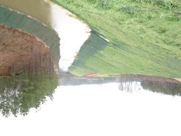
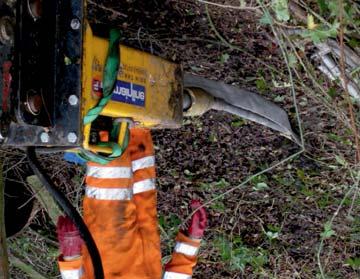
17 Case Study FLOOD PROTECTION WORKS, WATER OF LEITH - NEW ZEALAND Client: ORC Contractor: Lunds South Ltd PROJECT SPECIFICATION The Water of Leith is a river situated in the South-East of New Zealand that flows into the Otago Harbour opening out into the Pacific Ocean. Due to heavy rain and repeated flooding, the existing concrete river walls were removed and the angle of the slope was reduced to give the river more capacity in the event of further flooding. SOLUTION The flood plain of this river was to be lined with a geocell filled with top soil and covered with a turf reinforcement mat. Both the geocell and the turf reinforcement mat were anchored using 120 standard S6 ARGS anchor systems and 48 bespoke B4 anchor systems. Due to difficult access, two operatives were required to install the ARGS system using basic hand-held equipment. Approximately 80 anchors were installed, in very rocky ground, each day using a lightweight hydraulic hammer. 17

 to protect the surface.")

18 Case Study MARISCAL SUCRE INTERNATIONAL AIRPORT ACCESS, QUITO - ECUADOR Client: HCC Consultant: Ecuador Government Main Contractor: HCC PROJECT SPECIFICATION Steep cuts along the newly constructed access road to the airport required surface protection against deep erosion and shallow surface sliding. Traditional shotcrete methods were used on much of the easy access areas. The extremely high slopes posed difficulties for traditional methods so Platipus introduced the Anchor Reinforced Grid Solution (ARGS ) to protect the surface. The solution was employed and recently withstood a 5.1 earthquake on August 12th 2014 while other unprotected areas experienced some failures. SOLUTION The cut slopes were first protected with 2 layers of erosion control materials. The first provided the erosion protection and kept the surface soil from sliding down the slope. The top layer provided the strength to handle the load generated by the Percussive Driven Earth Anchor (PDEA ) as well as UV protection. 18


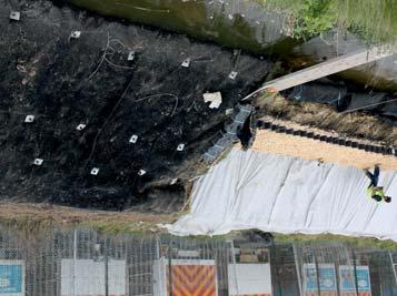
19 Case Study BANKS WOOD, DOWPITS LANE, APPLEBY-IN-WESTMORLAND, CUMBRIA - UK Client: Eden District Council Main Contractor & Anchor Installer: Vertical Access Ltd PROJECT SPECIFICATION This steep slope located alongside the River Eden has a history of instability and ground movement dating as far back as Further ground movement was observed in a previously untreated section of the slope approximately 50m wide. This led to loss of vegetation, an increase in shallow failures and accelerated weathering. Soil nailing was discarded as washout water and grout could not be allowed to contaminate the river, a Class 1 Special Area of Conservation, so an alternative solution was required. SOLUTION Alongside managed planting, two unique Platipus solutions were specified using a total of 274 anchors. The Platipus Anchored Reinforced Grid Solution (ARGS ) system combines two proven technologies, mechanical anchors and reinforced geogrid and was used to stabilize the slope and prevent further ground movement. 86 Active Plati-Drains were also incorporated into the design to provide simultaneous restraining and draining of the slope, reducing pore water pressure, soil lubrication and weathering. Future planting and an annual winter inspection is now all that is required to maintain this environmentally friendly scheme. 19


20 Case Study EGLIN AIR FORCE BASE, FLORIDA - USA Client: US Army Corp of Engineers Consultant: CTT Engineering, Wilmington, NC Main Contractor: CW Roberts Contracting PROJECT SPECIFICATION The US Army Corp of Engineers needed to stabilize an access road on to Santa Rosa Island. During tropical storms and hurricanes the road would overtop and eventually washout. The original solution was to drive steel sheet piling on each side of the road. In areas where the sheets were not parallel a concrete deadman was to be installed as a tie-back for the sheet piling. SOLUTION 1250 Platipus Anchors were installed to a depth 25' by Bridge Creek Construction, a certified Platipus Installer as an alternative to the tie-backs. Each anchor was loaded and certified to 40,000 lbs. 20


21 Case Study LANDFILL CAPPING ANCHORS - MOLEIGH & DALINLONGART, ARGYLE & BUTE - UK Client: Shanks Group Plc Consultant: Halcrow Main Contractor & Anchor Installer: Environmental Linings Ltd PROJECT SPECIFICATION To provide an anchoring system that would be capable of holding a multiple layered landfill capping solution over a steep gradient tip. An additional requirement was to provide a gas tight seal to prevent the escape of greenhouse gases into the atmosphere and also the ingress of rainwater that could generate ground polluting leachates. SOLUTION Laid out on a staggered 3m grid pattern, the anchors were driven straight through the laid membrane and directly into the landfill waste to a depth of approximately 1.4m. They were then load locked by hand before the polyethylene load plate and conical wedge grip were installed and sealed to the membrane using silicon mastic. The posidrain and UV layer were then laid and securely fixed using the top load plate and aluminium swage. 21


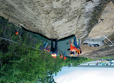
22 Case Study A1 AUTOSTRADA, MAJIEJOW, PIEKARY - POLAND Client: Polish Government Installer: A K G Architektura Krakjobrazu Main Contractor: Dragados PROJECT SPECIFICATION The A1 Autostrada is a north-south motorway that runs 568km through central Poland from Gdansk, on the Baltic Sea, through Lódz, to the Polish border in Gorzyczki where it connects to the Czech D1 motorway. As part of the upgrade a new section of motorway was constructed between Piekary and Maciejów which required an anchoring solution to secure all of the facing materials to three large new slopes. SOLUTION Early site testing revealed that the compacted granular fill was ideal for the Platipus mechanical anchor confirming that the small S6 anchor would easily achieve the 10kN ultimate load required by the Designer. Once construction of the motorway section was complete, soil was imported to create a new slope profile. A hydroseed mix was then sprayed over the freshly imported soil and a combination of coir mat and Geobrugg Tecco Mesh was secured tightly in place, by the Platipus S6 ARGS anchor system, to encourage immediate vegetation of the slope. Due to the height and gradient of the slope a hydraulic work platform was used to allow quick installation of the anchor system; using simple hand held equipment. On average a total of 130 anchor systems were installed each day which was much more than initially expected. 22
: Dickerson Florida, Inc.")


 along the canal.")
23 Case Study C-41A SEGMENT 2 & 3, FLORIDA - USA Client: South Florida Water Management District Installer: B&Z Diving Services LLC Contractor (Segment 2): ATL Diversified Industries Contractor (Segment 3): Dickerson Florida, Inc. PROJECT SPECIFICATION The South Florida Water Management District (SFWMD) operates and maintains flood control and water supplies in a 16-county region that stretches from Orlando to the Keys, reaching across the state of Florida from the Atlantic to the Gulf Coast. Over the last decade, hurricanes and tropical storms have stressed the canal system beyond its limit. Being a primary discharge from Lake Istokpoga to the Kissimmee River feeding Lake Okeechobee, C-41A suffered an extensive amount of erosion and SFWMD elected to restore the canal banks to achieve a higher water quality standard and prevent future erosion. SOLUTION The restoration of the canal included the removal of the existing vegetation, backfilling, regrading and compacting the slope to 2.5H:1V, and re-vegetating. Working topside with heavy machinery and an underwater diving team, anchors were driven into the slope to hold down a high performance turf reinforcement mat (HPTRM) along the canal. The HPTRM was selected as the erosion control system because of its ability to withstand mild wave-action and long term submergence. The system is comprised of a non-woven geotextile, an HPTRM, and a Platipus S2 ARGS Anchor. For this application, the anchors are serving as a tie down anchor. They are simply holding the HPTRM tight against the face of the slope in order to guard against erosion while vegetation is being established. This design was critical to withstand the shear forces brought on by high volume flows that exceed the limits of the natural vegetation. The project required a 50 year design life in brackish conditions. The anchors were specified with a minimum drive depth of 36 inches with spacing at 4 feet along the vertical overlaps of the HPTRM, top anchor trench, and the submerged bottom trench. 23


 or Plati-Klein (PHK), Setting")


24 INSTALLATION TOOLS Over many years we have developed a wide range of bespoke equipment to provide customers with well engineered, high quality, durable and practical installation tools designed for sustained use. Light Installation Our range of stealth anchors up to and including the S6 can be installed using simple hand tools. The S2, S4 and S6 variants need only a Drive Rod, Plati-Hook (PH1) or Plati-Klein (PHK), Setting Plate / Bobbin and optionally Rod Removers (RR1). The anchors can be installed using a sledgehammer or postrammer which can be sourced locally. In multiple anchor installations electric, light air or hydraulic hammers make higher production rates fast and easy. The Manual Stressing Jack (SJ1) will provide up to 10kN of uplift to loadlock and proof test the anchors. The Stressing Jack (SJ3) is an extremely compact solution for loadlocking / stressing multiple anchor installations particularly on steep slopes up to 10 kn. Medium / Heavy Installation The installation of the S8 and B4 anchors typically require larger installation tools. Manual or Hydraulic Stressing equipment and Rod Removers are useful accessories. For multiple installations the use of hand or powered Hydraulic Stressing equipment is advised. The B 6, B8 and B10 Bat anchors will normally be used in either Deep Seated Failures or Cut Face Slopes. Installation equipment will vary from portable Hydraulic to Machine Mounted Hammers, Drive Rods, Rod Removers and Hydraulic Stressing equipment. In all cases let us advise you of our recommendations for equipment choice based upon your project s criteria. 24
 The S2 Geo is typically used for")


 loadlock the anchor into its full")
 push the plastic cap down tight to")
.")


 or Power Drive Rod")


 squeeze open the jaws and place the wire")


25 Installation Instructions for S2 Geo Anchored Reinforced Grid Solutions Percussive Driven Earth Anchor (PDEA ) The S2 Geo is typically used for Surface Erosion and is often spaced at 1 anchor per sq. m / yd. Field adjustments can be made according to site conditions and anchor holding capacity. If the grade is smooth and raked free of rocks and debris, the anchor spacing may be increased slightly. Consult a qualified engineer for specific requirements. 1 Using the Platipus Hand Drive Rod (HDRS2) or Power Drive Rod (PDRS2) drive the anchor system into the ground to the required installation depth. 2 Remove the Hand Drive Rod or Power Drive Rod from the body of the anchor by hand. 3 Using the Platipus Plati-Hook (PH1) loadlock the anchor into its full working position by applying a load to the wire tendon. 4 Using the Platipus Hand Swage Tool (HS3) push the plastic cap down tight to the surface protection material using the foot plate (this should create a slight indentation of the cap into the surface protection material). Then swage the copper ferrule tightly against the cap. 5 Cut off excess tendon at the ferrule and discard accordingly. The surface protection material should be visibly tight between one anchor and the next. As a test, the material between them should not be easily lifted maintaining intimate contact between the surface protection material and the soil below. If this does not occur install an additional anchor. Installation Instructions for S2 ARGS Anchored Reinforced Grid Solutions Percussive Driven Earth Anchor (PDEA ) The S2 ARGS is typically used for Surface Erosion and is often spaced at 1 anchor per sq. m / yd. Field adjustments can be made according to site conditions and anchor holding capacity. If the grade is smooth and raked free of rocks and debris, the anchor spacing may be increased slightly. Consult a qualified engineer for specific requirements. 1 Using the Platipus Hand Drive Rod Remove the Hand (HDRS2) or Power Drive Rod (PDRS2) drive Drive Rod or Power the anchor system into the ground to the required Drive Rod from the body installation depth. of the anchor by hand. 2 3 Remove the black plastic cap from the wire tendon and carefully insert the wire tendon into the wedge grip. Thread the wire tendon fully through and push down on the wedge grip to seat the assembly against the surface protection material. 4 Thread the wire tendon through the setting plate. Using the Platipus Plati-Klein ( PHK) squeeze open the jaws and place the wire tendon in the middle. Then loadlock the anchor into its full working position by applying a load to the wire tendon. 5 Place both feet over the setting plate keeping it level to the load plate and continue to apply a load until satisfied. Remove the Plati-Klein and the setting plate. 6 Cut off excess tendon and discard accordingly. The surface protection material should be visibly tight between one anchor and the next. As a test, the material between them should not be easily lifted maintaining intimate contact between the surface protection material and the soil below. If this does not occur install an additional anchor. 25
 The S4 / S6")


 or Power Drive")


.")


.")
 and pull with two people as depicted.")
 5 6 Using the")


, then use the lever to")


26 Installation Instructions for S4 / S6 ARGS Anchored Reinforced Grid Solutions Percussive Driven Earth Anchor (PDEA ) The S4 / S6 ARGS is a flexible engineered solution for stabilizing Shallow Slide Failure embankments. The Surface Protection Material will protect the slope face from erosion as well as spread the load of the driven anchors across the slope face. The anchors must be driven and loadlocked in place beyond the failure plane at an engineered depth and spacing to provide a secured embankment. Once installed the system can be easily vegetated. 1 Using the Platipus Hand Drive Rod (HDRS4ED/HDRS6) or Power Drive Rod (PDRS4ED/PDRS6) drive the anchor system into the ground to the required engineered installation depth. Invert if using the postrammer to finish off the driving. 2 Remove the Hand Drive Rod or Power Drive Rod from the body of the anchor, either by hand or by using the optional Rod Removers (RR1). Loadlocking / Setting by Hand 3 Remove the black plastic cap from the wire tendon and carefully insert the wire tendon into the wedge grip. Thread the wire tendon fully through the load plate and push down on the wedge grip to seat the assembly against the Surface Protection Material. Thread the wire tendon through the setting plate and place on top of the load plate. 4 Place both feet over the setting plate keeping it flat against the load plate and apply a load using the Plati-Klein (PHK). Where necessary you can pass the drive rod through the handle of the Plati- Klein (PHK) and pull with two people as depicted. Release the wire from the PHK. Now refer to Section 8. Loadlocking / Setting with Stressing Jack (SJ1) 5 6 Using the Stressing Jack (SJ1) with the Geoblock and bobbin connect the wire tendon to the klein and then ensure the wire tendon is tightly located within the Geoblock. Using the lever on the jack apply a load as necessary to both loadlock the anchor and apply the required load. Once the load has been established tap the bobbin down gently to seat the wedges. Push the catch down on the jack (as shown), then use the lever to release the load, release the wire tendon from the klein. Cut off any excess wire once satisfied. Now refer to Section 8. Loadlocking / Setting with Stressing Jack (SJ3) 7 Using the Stressing Jack (SJ3) thread the bobbin over the wire 8 tendon and then connect to the klein and ensure it is tightly located in the back of the slot. Using the hand pump, apply the required load to loadlock and set the anchor, if required take a second bite at the wire tendon by releasing the pressure on the jack and re-attaching the klein. Tap gently on the bobbin then release the pressure and remove the wire tendon from the klein, remove the SJ3. Cut off excess tendon and discard accordingly. The Surface Protection Material should be visibly tight between one anchor and the next. As a test, the material between them should not be easily lifted maintaining intimate contact between the Surface Protection Material and the soil below. If this does not occur install an additional anchor. 26


27 DESIGN CONSIDERATIONS 3 Anchor Trench Anchor Trench What is the soil type / conditions where the anchor will reside? What is the vertical height of the embankment? What is the slope angle? How deep is the failure plane? Is there pore water pressure within the embankment? Using a standard geotechnical embankment stabilization program, how much load needs to be applied to the surface to stabilize the slope? What is the factor of safety (usually between 1.2 to 1.5)? What is the design life? 27


28 Distributor Cirtex Australia Ltd Level 9 1 Corporate Court BUNDALL QLD 4217 Australia P: E: info@cirtex.com.au W: PDEA, ARGS and ARVS are Registered Trademarks of Platipus Anchors
SIMPLY HOW A MECHANICAL ANCHOR WORKS
 INTRODUCTION TO ARGS Anchored Reinforced Grid Solutions Stabilizing slopes offers many significant challenges. Platipus combine Percussion Driven Earth Anchors (PDEA ) with a suitable surface or facing
SIMPLY HOW A MECHANICAL ANCHOR WORKS
 INTRODUCTION TO ARGS Anchored Reinforced Grid Solutions Stabilizing slopes offers many significant challenges. Platipus combine Percussion Driven Earth Anchors (PDEA ) with a suitable surface or facing
EARTH ANCHORING SYSTEMS FOR UNDERWATER, MARINE & SHORELINE APPLICATIONS
 EARTH ANCHORING SYSTEMS FOR UNDERWATER, MARINE & SHORELINE APPLICATIONS INTRODUCTION Platipus Anchors are market leaders in the design, manufacture and supply of mechanical earth anchoring products. We
Pioneers of alternative anchoring solutions with Cirtex Australia Ltd
 Pioneers of alternative anchoring solutions with Cirtex Australia Ltd Platipus Anchors are market leaders in the design, manufacture and supply of mechanical earth anchoring products for a range of industries
EARTH ANCHORING SYSTEMS FOR UNDERWATER, MARINE & SHORELINE APPLICATIONS PLATIPUS EARTH ANCHORING SYSTEMS
 EARTH ANCHORING SYSTEMS FOR UNDERWATER, MARINE & SHORELINE APPLICATIONS PLATIPUS EARTH ANCHORING SYSTEMS INTRODUCTION Platipus Anchors are market leaders in the design, manufacture and supply of mechanical
North America s leader of complete geosynthetic solutions. Golf Course Solutions. To view our complete product line visit us at
 North America s leader of complete geosynthetic solutions Golf Course Solutions To view our complete product line visit us at www.terrafixgeo.com A golf course requires attentive and competent management.
ARMORMAX ENGINEERED EARTH ARMORING SOLUTIONS
 ARMORMAX ENGINEERED EARTH ARMORING SOLUTIONS The ARMORMAX Engineered Earth Armoring Solution is the most advanced flexible armoring technology available for severe erosion and surficial slope stability
Geoguide 6 The New Guide to Reinforced Fill Structure and Slope Design in Hong Kong
 Geoguide 6 The New Guide to Reinforced Fill Structure and Slope Design in Hong Kong Geotechnical Engineering Office Civil Engineering Department The Government of the Hong Kong Special Administrative Region
SIMPLY HOW A MECHANICAL ANCHOR WORKS
 INTRODUCTION TO PDEA Percussion Driven Earth Anchors Platipus has over 35 years of experience in the design, manufacture and supply of Percussion Driven Earth Anchors (PDEA ) for a wide variety of market
Product Guide. Fabric-formed Concrete Erosion Control and Armoring Systems. Filter Point. Filter Band. Uniform Section. Enviromat. Articulating Block
 Filter Point Filter Band Uniform Section Enviromat Articulating Block Hydrocast Armor Units Fabric-formed Concrete Erosion Control and Armoring Systems Product Guide Filter Point (FP) Linings Filter Band
Solving Slope Protection Problems Geoweb Cellular Confinement System
 Solving Slope Protection Problems Geoweb Cellular Confinement System Leaders In Advanced Geotechnology TM Slope Protection An Engineered Framework for Slope Protection The Presto Geoweb Cellular Confinement
I
 PIPELINE INTERNATIONAL EROSION CONTROL SYSTEMS INC. 855.768.1420 I www.iecsusa.com SLOPE DAM OVERTOPPING PROTECTION BOAT RAMP BRIDGE SCOUR Effective Erosion Control AFTER BEFORE DIVERSION CHANNEL Page
Low Gradient Velocity Control Short Term Steep Gradient Channel Lining Medium-Long Term Outlet Control Soil Treatment Permanent [1]
![Low Gradient Velocity Control Short Term Steep Gradient Channel Lining Medium-Long Term Outlet Control Soil Treatment Permanent [1]](/thumbs/83/88729038.jpg "Low Gradient Velocity Control Short Term Steep Gradient Channel Lining Medium-Long Term Outlet Control Soil Treatment Permanent [1]") Diversion Channels DRAINAGE CONTROL TECHNIQUE Low Gradient Velocity Control Short Term Steep Gradient Channel Lining Medium-Long Term Outlet Control Soil Treatment Permanent [1] [1] The design of permanent
Diversion Channels DRAINAGE CONTROL TECHNIQUE Low Gradient Velocity Control Short Term Steep Gradient Channel Lining Medium-Long Term Outlet Control Soil Treatment Permanent [1] [1] The design of permanent
SECTION MECHANICALLY STABILIZED EARTH 1.01 SUMMARY
 SECTION 028300 PART 1 GENERAL 1.01 SUMMARY A. Section includes Basis of Design Mechanically Stabilized Earth System: SierraScape Mechanically Stabilized Earth (MSE) retaining wall system having high density
ArmorFlex. Articulating Concrete Block Revetment System
 ArmorFlex Articulating Concrete Block Revetment System ArmorFlex ASTM-validated system lets you design with confidence ArmorFlex is in a class by itself. Developed for high-scour, high-flow applications,
GEOTECHNICAL SERVICES
 GEOTECHNICAL SERVICES Aarsleff Ground Engineering EXPERIENCE: Aarsleff s expertise as Ground Engineers is evidenced not only by its 25 years in UK construction and its dedicated staff, but in the decades
Temporary Watercourse Crossing: Culverts
 Temporary Watercourse Crossing: Culverts DRAINAGE CONTROL TECHNIQUE Low Gradient Velocity Control Short Term Steep Gradient Channel Lining Medium-Long Term Outlet Control Soil Treatment Permanent Symbol
 UNIT V RETAINING WALLS RETAINING WALL 2.5. Retaining walls are structures used to retain earth or water or other materials such as coal, ore, etc; where conditions do not permit the mass to assume its
Save time. Save money. Specify a fast, economical Vist-A-Wall MSE. fast and easy to install. They adapt well to curves, angles and
 bigrbridge.com Save time. Save money. Specify a fast, economical Vist-A-Wall MSE Structural Wall System for your next engineered embankment project. These historically-proven, cost-effective systems have
GEOWEB. slope and shoreline protection. environments. creating sustainable APPLICATION OVERVIEW
 GLOBAL LEADER GLOBAL PARTNER creating sustainable environments GEOWEB slope and shoreline protection APPLICATION OVERVIEW our commitment: providing the highest quality products/solutions eco-economic solutions
TABLE OF CONTENTS. 0 Structural calculations 0.1 General 0.2 Safety concept 0.3 Calculations for waterfront structures
 Arbeitsausschuß "Ufereinfassungen" der Hafentechnischen Gesellschaft e.v. Recommendations of the Committee for Waterfront Structures Harbours and Waterways 9., completely revised Edition TABLE OF CONTENTS
BLOCKING AND FILLING SURFACE DRAINAGE DITCHES
 MINNESOTA WETLAND RESTORATION GUIDE BLOCKING AND FILLING SURFACE DRAINAGE DITCHES TECHNICAL GUIDANCE DOCUMENT Document No.: WRG 4A-1 Publication Date: 10/14/2015 Table of Contents Introduction Application
MECHANICALLY STABILIZED EARTH (MSE) WALL SYSTEMS
 WALL SYSTEMS") DRAINAGE SOLUTIONS SINCE 1908 MECHANICALLY STABILIZED EARTH (MSE) WALL SYSTEMS PERMANENT AND TEMPORARY ENGINEERED WALL SOLUTIONS ECONOMICAL DURABLE VERSATILE ARMTEC.COM MSE RETAINING WALLS Armtec Mechanically
DRAINAGE SOLUTIONS SINCE 1908 MECHANICALLY STABILIZED EARTH (MSE) WALL SYSTEMS PERMANENT AND TEMPORARY ENGINEERED WALL SOLUTIONS ECONOMICAL DURABLE VERSATILE ARMTEC.COM MSE RETAINING WALLS Armtec Mechanically
SECTION SPECIFICATION FOR MECHANICALLY STABILIZED EARTH TWO STAGE WALL SYSTEM
 SECTION 02830 SPECIFICATION FOR MECHANICALLY STABILIZED EARTH TWO STAGE WALL SYSTEM ## THIS SECTION IS WRITTEN IN CSI 3-PART FORMAT AND IN CSI PAGE FORMAT. NOTES TO THE SPECIFIER, SUCH AS THIS, ARE INDICATED
Design and Installation Guidelines for Retaining Walls. 1 P age. Geo Products, LLC 8615 Golden Spike Lane Houston, TX Phone:
 Design and Installation Guidelines for Retaining Walls 1 P age Geo Products, LLC 8615 Golden Spike Lane Houston, TX 77086 Phone: 281.820.5493 2011 Geo Products, Fax: 281.820.5499 LLC www.geoproducts.org
Block and gravel filters can be used where velocities are higher. Reduces the amount of sediment leaving the site.
 INLET PROTECTION From Massachusetts Erosion and Sediment Control Guidelines for Urban and Suburban Areas http://www.state.ma.us/dep/brp/stormwtr/files/esfull.pdf Definition: A sediment filter or an excavated
MagnumStone Specifications Gravity
 MagnumStone Specifications Gravity SPECIFICATION FOR MAGNUMSTONE GRAVITY MECHANICALLY STABILIZED EARTH SYSTEM PART 1: GENERAL.01Description The work consists of supplying and installing all aspects of
Specialising in Ground Engineering & Slope Stabilisation
 Specialising in Ground Engineering & Slope Stabilisation Ground Engineering & Slope Stabilisation for the Road, Rail, Construction & Mining Industries Company Profile Warner Company is proudly an Australian
Seismically induced landslide mitigation using flexible slope stabilisation systems
 Seismically induced landslide mitigation using flexible slope stabilisation systems S. Farrand Geovert (NZ) Ltd, Christchurch, New Zealand. A. Teen Geobrugg (NZ) Ltd, Christchurch, New Zealand. 2008 NZSEE
GEOWEB retaining walls OVERVIEW
 SOIL STABILIZATION GEOWEB retaining walls OVERVIEW GEOWEB RETAINING WALLS Retaining walls built with the GEOWEB system are an economical, green alternative to MSE wall systems creating a naturally-vegetated
Chapter 8 Anchoring Structures
 Chapter 8 Anchoring Structures 8-1. General Structural anchors are often used to improve the stability of existing structures but, generally, should not be used as a primary means to stabilize new, large
SPECIFICATIONS FOR PRECAST MODULAR BLOCK RETAINING WALL SYSTEM (revised 5/8/7)
") Page 1 of 7 STONE STRONG SYSTEMS SPECIFICATIONS FOR PRECAST MODULAR BLOCK RETAINING WALL SYSTEM (revised 5/8/7) PART 1: GENERAL 1.01 Description A. Work includes furnishing and installing precast modular
Page 1 of 7 STONE STRONG SYSTEMS SPECIFICATIONS FOR PRECAST MODULAR BLOCK RETAINING WALL SYSTEM (revised 5/8/7) PART 1: GENERAL 1.01 Description A. Work includes furnishing and installing precast modular
A complex reinforced structure applied at hilly road repair case in Taiwan
 A complex reinforced structure applied at hilly road repair case in Taiwan Introduction In the filed of geotechnical engineering, frequently soil nailing is applied to the application of the shallow-depth
Retaining Wall System
 Your local distributor Retaining Wall System Prestige & Quality Near Vertical Walls Do It Yourself No Concrete Footings Flexible - 90 o Corners, Steps, Straight or Curved Walls Commercial or Civil Walls
Tasman and Norfolk Retaining Wall
 Tasman and Norfolk Retaining Wall Evaluation and Installation Guide BAINES We deliver Sydney s Best! Order online: bcsands.com.au Call: (02) 8543 3400 Taren Point & Mascot Tasman and Norfolk are registered
Modular Sediment Barriers (Instream)
") Modular Sediment Barriers (Instream) INSTREAM PRACTICES Flow Control No Channel Flow Dry Channels Erosion Control Low Channel Flows Shallow Water Sediment Control High Channel Flows Deep Water Symbol Photo
Modular Sediment Barriers (Instream) INSTREAM PRACTICES Flow Control No Channel Flow Dry Channels Erosion Control Low Channel Flows Shallow Water Sediment Control High Channel Flows Deep Water Symbol Photo
INNOVATIVE SLOPE STABILISATION BY USING ISCHEBECK TITAN SOIL NAILS
 Dipl.-Wirt.Ing. Oliver Freudenreich Friedr. Ischebeck GmbH phone: ++49 2333 8305-0 Loher Str. 31 79 fax: ++49 2333 8305-55 e-mail: freudenreich@ischebeck.de D-58256 Ennepetal www.ischebeck.com INNOVATIVE
STREAMBANK RESTORATION DESIGN
 STREAMBANK RESTORATION DESIGN WITH VINYL SHEET PILE GRADE CONTROL STRUCTURES BRUCE M. PHILLIPS, M.S., P.E. ABSTRACT Grade control structures are an effective channel stabilization measure which can eliminate
MSE WALLS CASE STUDIES. by John G. Delphia, P.E. TxDOT Bridge Division Geotechnical Branch
 MSE WALLS CASE STUDIES by John G. Delphia, P.E. TxDOT Bridge Division Geotechnical Branch COMMON RETAINING WALL TYPES CONCRETE BLOCK MSE TEMPORARY EARTH SPREAD FOOTING Gabions Drilled Shaft Soil Nail Tiedback
Classification of slope
 Slope Protection Classification of slope Natural slope in various conditions, including rock slope Man-made slope - including cut-back slope or slope formed by filled material with adequate compaction,
Tasman Retaining Wall
 Tasman Retaining Wall EVALUATION AND INSTALLATION GUIDE Landscaping Tasman Retaining Wall Evaluation and Installation Guide This installation guide demonstrates the basics on how to construct: A. Tasman
RPC Contracts is committed to innovative product development and manufacture. T o help you obtain maximum enjoyment and long service from any RPC
 RPC Contracts is committed to innovative product development and manufacture. T o help you obtain maximum enjoyment and long service from any RPC Contracts product, we would be pleased to make you aware
A Complete Retaining Wall Solution >
 SYSTEM OVERVIEW Tensar Geogrids SierraScape Walls now offer a more affordable alternative to concrete for steep grade changes. The SierraScape System owes its strength and durability to Uniaxial (UX) Geogrids,
Earth Retaining System
 Hashemite University Department of Civil Engineering Foundation Engineering Dr. Omar Al-Hattamleh Earth Retaining System Earth slopes and earth retaining structures Used to maintain two different ground
Embankments. Bridging of Sinkholes. Motorway A1 in Poland: Pyrzowice Piekary Śląskie Maciejów. Project. Introduction
 Motorway A1 in Poland: Pyrzowice Piekary Śląskie Maciejów HUESKER has successfully completed the biggest geosynthetic project in the history of the company Fig. 1: General view on one section of the A1
SECTION SPECIFICATION FOR STONEBRIDGE RETAINING WALL SYSTEM
 SECTION 32 32 23 SPECIFICATION FOR STONEBRIDGE RETAINING WALL SYSTEM PART 1: GENERAL 1.01 Scope Work includes furnishing all materials, labor, equipment, and supervision to install a Stonebridge segmental
CONTENTS. Cellular Confinement System INTRODUCTION MATERIALS Multi-Cell Fill... 2
 Johannesburg +27 (0)11 922 3300 Pinetown +27 (0)31 717 2300 Cape Town +27 (0)21 531 8110 East London +27 (0)43 727 1055 www.kaytech.co.za Cellular Confinement System CONTENTS INTRODUCTION... 2 1. MATERIALS...
Common Construction-Site BMPs Quick Reference Guide
 Common Construction-Site BMPs Quick Reference Guide Installation and Inspection Requirements For more information visit the Town of Truckee Clean Water Program Website: http://www.townoftruckee.com/engineering/clean-water-program
Filter Tube Barriers (Instream)
") Filter Tube Barriers (Instream) INSTREAM PRACTICES Flow Control No Channel Flow Dry Channels Erosion Control Low Channel Flows Shallow Water Sediment Control High Channel Flows Deep Water Symbol Photo
Filter Tube Barriers (Instream) INSTREAM PRACTICES Flow Control No Channel Flow Dry Channels Erosion Control Low Channel Flows Shallow Water Sediment Control High Channel Flows Deep Water Symbol Photo
SWPPP Cut Sheet: Filtrexx Vegetated Retaining Walls
 2: Storm Water Management Post-Construction SWPPP Cut Sheet:.10Section Filtrexx Vegetated Retaining Walls Vegetated Mechanically Stabilized Earth (MSE) Technology PURPOSE & DESCRIPTION Vegetated retaining
SPECIFICATION FOR CORNERSTONE GEOGRID REINFORCED SEGMENTAL RETAINING WALL SYSTEM
 CornerStone Specifications Geogrid Reinforced SPECIFICATION FOR CORNERSTONE GEOGRID REINFORCED SEGMENTAL RETAINING WALL SYSTEM PART 1: GENERAL 1.01 Description The work consists of supplying and installing
USACE Approved Application Projects Levee Overtopping/Overwash Channels Ponds / Storage Lagoons Bank Stabilization Dike Repair Slope Stability Canal
 USACE Approved Application Projects Levee Overtopping/Overwash Channels Ponds / Storage Lagoons Bank Stabilization Dike Repair Slope Stability Canal / River Bank Stabilization Dam Overflow Structure Project
Miller Collective Safety at Height Solutions EPIC ULTRA Barrier System EPIC Post-N-Barrier System EPIC Basic Barrier System
 For over 65 years the Miller brand has been synonymous with personal fall protection products and services. As the global leader in safety at height solutions, Honeywell Safety Products introduces a new
Bowling Green, Kentucky Stormwater Best Management Practices (BMPs) Sediment Management Practices (SMPs) Activity: Temporary Inlet Protection (TIP)
 Sediment Management Practices (SMPs) Activity: Temporary Inlet Protection (TIP)") Bowling Green, Kentucky Stormwater Best Management Practices (BMPs) Sediment Management Practices (SMPs) Activity: Temporary Inlet Protection (TIP) SMP-11 PLANNING CONSIDERATIONS: Design Life: 1 yr Acreage
Bowling Green, Kentucky Stormwater Best Management Practices (BMPs) Sediment Management Practices (SMPs) Activity: Temporary Inlet Protection (TIP) SMP-11 PLANNING CONSIDERATIONS: Design Life: 1 yr Acreage
Flow Diversion Banks: General
 Flow Diversion Banks: General DRAINAGE CONTROL TECHNIQUE Low Gradient Velocity Control Short Term Steep Gradient Channel Lining Medium-Long Term Outlet Control Soil Treatment Permanent [1] [1] Flow diversion
Plastic Piling Solutions
 Introduction Planet 14 Landscapes Ltd began supplying and installing plastic piling in 2009. One of our very first projects involved the stablisation of a bank around a moat for a private client. We are
Lake Summerset Shoreline Types. Prepared by the Lake Summerset Lake Planning Committee Revision 2013-MAR-27
 Lake Summerset Shoreline Types Prepared by the Lake Summerset Lake Planning Committee Revision 2013-MAR-27 PREFACE Lake Summerset Association s Lake Planning Committee (LPC) maintains a membership of knowledgeable,
GEOWEB Soil Stabilization System
 GEOWEB Soil Stabilization System The Most Complete Geocell System HDPE GEOWEB STRENGTH AND FLEXIBILITY PERFECTED. For the most advanced soil stabilization technology today, rely on the world s most proven
GEOWEB Soil Stabilization System
 GEOWEB Soil Stabilization System The Most Complete Geocell System HDPE GEOWEB STRENGTH AND FLEXIBILITY PERFECTED. For the most advanced soil stabilization technology today, rely on the world s most proven
Low Gradient Velocity Control Short Term Steep Gradient Channel Lining Medium-Long Term Outlet Control [1] Soil Treatment Permanent
![Low Gradient Velocity Control Short Term Steep Gradient Channel Lining Medium-Long Term Outlet Control [1] Soil Treatment Permanent](/thumbs/86/94770055.jpg "Low Gradient Velocity Control Short Term Steep Gradient Channel Lining Medium-Long Term Outlet Control [1] Soil Treatment Permanent") Slope Drains DRAINAGE CONTROL TECHNIQUE Low Gradient Velocity Control Short Term Steep Gradient Channel Lining Medium-Long Term Outlet Control [1] Soil Treatment Permanent [1] Slope drains can act as outlet
Slope Drains DRAINAGE CONTROL TECHNIQUE Low Gradient Velocity Control Short Term Steep Gradient Channel Lining Medium-Long Term Outlet Control [1] Soil Treatment Permanent [1] Slope drains can act as outlet
Low Gradient Velocity Control Short Term Steep Gradient Channel Lining Medium-Long Term Outlet Control [1] Soil Treatment Permanent
![Low Gradient Velocity Control Short Term Steep Gradient Channel Lining Medium-Long Term Outlet Control [1] Soil Treatment Permanent](/thumbs/87/96161482.jpg "Low Gradient Velocity Control Short Term Steep Gradient Channel Lining Medium-Long Term Outlet Control [1] Soil Treatment Permanent") Slope Drains DRAINAGE CONTROL TECHNIQUE Low Gradient Velocity Control Short Term Steep Gradient Channel Lining Medium-Long Term Outlet Control [1] Soil Treatment Permanent [1] Slope drains can act as outlet
Slope Drains DRAINAGE CONTROL TECHNIQUE Low Gradient Velocity Control Short Term Steep Gradient Channel Lining Medium-Long Term Outlet Control [1] Soil Treatment Permanent [1] Slope drains can act as outlet
Anchorplex retaining wall construction guide
 Anchorplex retaining wall construction guide Building Anchorplex Retaining Wall Systems Table of Contents and Introduction table of contents ow to Use This Guide......................... 2 About the Anchorplex
Tasman Retaining Wall System
 Tasman Retaining Wall System The Tasman Retaining Wall System incorporates purpose made corners and capping units to provide classical reconstructed stone retaining walls for any landscape situation. From
A.2.a Random Riprap... Table
 3601 RIPRAP MATERIAL 3601.1 SCOPE Provide stone and filter layer material for use in random or hand-placed riprap, gabion, and revet mattress construction. 3601.2 REQUIREMENTS A Stones A.1 Quality Provide
Paul Brunner, Larry Dacus, Doug Handen. Repairs to Concrete-Lined V-Ditch Alternatives Evaluation
 Memo To: Paul Brunner, Larry Dacus, Doug Handen From: Alberto Pujol /Dan Wanket Date: 09/10/2010 Re: Feather River Levee Site 7 Extension Repairs to Concrete-Lined V-Ditch Alternatives Evaluation This
11.1 INTRODUCTION 11.2 SLOPE MANAGEMENT SYSTEM 11.1 GEOTECHNICAL AND SLOPE STABILITY
 CHAPTER 11. GEOTECHNICAL AND SLOPE STABILITY 11.1 INTRODUCTION Geotechnical and stability related problems can occur on cut and fill slopes. These can be in the following forms: Subsidence resulting in
Block & Aggregate Drop Inlet Protection
 Block & Aggregate Drop Inlet Protection SEDIMENT CONTROL TECHNIQUE Type 1 System Sheet Flow Sandy Soils Type 2 System [1] Concentrated Flow Clayey Soils Type 3 System Supplementary Trap Dispersive Soils
Temporary Watercourse Crossing: Fords
 Temporary Watercourse Crossing: Fords DRAINAGE CONTROL TECHNIQUE Low Gradient Velocity Control Short Term Steep Gradient Channel Lining Medium-Long Term Outlet Control Soil Treatment Permanent [1] [1]
Inlet Protection. Fe= (Depends on soil type)
") 3.4 DESIGN CRITERIA: KEY CONSIDERATIONS Evaluate drainage patterns to ensure inlet protection will not cause flooding of roadway, property or structures Never block entire inlet opening Size according
3.4 DESIGN CRITERIA: KEY CONSIDERATIONS Evaluate drainage patterns to ensure inlet protection will not cause flooding of roadway, property or structures Never block entire inlet opening Size according
Best Management Practice (BMP) Guidance Manual
 Guidance Manual") Best Management Practice (BMP) Guidance Manual INTRODUCTION BMP examples in this guide provide ways to meet erosion and sediment control requirements. Best Management Practices are not limited to these
Best Management Practice (BMP) Guidance Manual INTRODUCTION BMP examples in this guide provide ways to meet erosion and sediment control requirements. Best Management Practices are not limited to these
ROLLED EROSION CONTROL PRODUCTS (RECP)
") Supplemental Technical Specification for ROLLED EROSION CONTROL PRODUCTS (RECP) SCDOT Designation: SC-M-815-9 (07/17) 1.0 Rolled Erosion Control Products (RECP) This Supplemental Specification replaces
Supplemental Technical Specification for ROLLED EROSION CONTROL PRODUCTS (RECP) SCDOT Designation: SC-M-815-9 (07/17) 1.0 Rolled Erosion Control Products (RECP) This Supplemental Specification replaces
2-16 EROSION, SEDIMENT & STORM WATER CONTROL REGULATIONS APPENDIX B1
 2-16 EROSION, SEDIMENT & STORM WATER CONTROL REGULATIONS APPENDIX B1 There are three ways to accomplish urban soil erosion and sedimentation control: Allow erosion to take place and then control sediment
Anchorplex retaining wall construction guide. Building. Anchorplex. Retaining Wall Systems
 Anchorplex retaining wall construction guide Building Anchorplex Retaining Wall Systems Table of Contents and ow to Use This Guide table of contents ow to Use This Guide. 2 About the Anchorplex System.
City of Doral 8401 NW 53 rd Ter. Doral, FL 33166
 City of Doral 8401 NW 53 rd Ter. Doral, FL 33166 Project Address: (305) 593-6700 Permit Number: National Pollution Discharge Elimination System (NPDES) Construction Site Erosion and Sedimentation Control
the PREMIUM WATER APPLICATION P E T R A T E C H
 the PREMIUM WATER APPLICATION E A R T H D A M S S H O R E L I N E S L O C A L S C O U R C O N S T R I C T I O N S C O U R C A N A L S C H A N N E L S W A T E R C O N T R O L S P I L L W A Y S R I V E R
component developments Stainless Steel Industrial Floor Drainage
 component developments Stainless Steel Industrial Floor Drainage Component Developments What we do We design, manufacture and supply standard, adapted and bespoke stainless steel building products. We
COUNTY BLOCK. Construction Guidelines on County Block Steps. Special Considerations When Building Steps. Natural Beauty Absolute Strength
 Construction Guidelines on County Block Limits of Liability This County Block Installation Guide provides general information about the product, including installation procedures, technical and engineering
HUITEX GEOCELL INSTALLATION MANUAL
 Table of Contents 1 Site Preparation 2 Installation for the Retaining Wall 2.1 Base Preparation 2.2 Footing Installation 2.3 Placement of the Drainage System 2.4 Placement of the HUITEX Geocell panels
THE SMART WAY TO CONTROL OPEN CHANNEL FLOW COUNCIL CASE STUDIES. Greg Farrell & Josh Lopez. Geofabrics Australasia Pty Ltd
 THE SMART WAY TO CONTROL OPEN CHANNEL FLOW COUNCIL CASE STUDIES Paper Presented by: Greg Farrell & Josh Lopez Authors: Greg Farrell, Development Manager, Josh Lopez, Technical Support Engineer, Geofabrics
Channel FlexTM P-BD Series
 Channel FlexTM P-BD Series Class 475 Closed Cell 4.75 Cellular Concrete Block Mat System TABLE OF CONTENTS FOR ARTICULATED CONCRETE BLOCK REVETMENT PARAGRAPH PARAGRAPH TITLE PAGE PART 1 - GENERAL 1.1 DEFINITIONS
SEPA Environmental Checklist Mercer Island Center for the Arts. Attachment F Geotechnical Supplemental Memo
 SEPA Environmental Checklist Mercer Island Center for the Arts Attachment F Geotechnical Supplemental Memo January 2017 MEMORANDUM DATE: May 6, 2015 TO: FROM: RE: CC: Katie Oman, Mercer Island Center for
SPECIFICATION FOR MAGNUMSTONE GEOGRID REINFORCED Mechanically Stabilized Earth (MSE) SYSTEM
 SYSTEM") MagnumStone Specifications Geogrid Reinforced SPECIFICATION FOR MAGNUMSTONE GEOGRID REINFORCED Mechanically Stabilized Earth (MSE) SYSTEM PART 1: GENERAL 1.01 Description The work consists of supplying
MagnumStone Specifications Geogrid Reinforced SPECIFICATION FOR MAGNUMSTONE GEOGRID REINFORCED Mechanically Stabilized Earth (MSE) SYSTEM PART 1: GENERAL 1.01 Description The work consists of supplying
INS T A LLA T I O N G U I D E
 INS T A LLA T I O N G U I D E TENSAR GEOGRIDS The System is a costeffective and easy-to-install alternative for projects with grade changes. The System owes its long-term performance and durability to
Redi Rock Specification and Installation Manual
 Redi Rock Specification and Installation Manual 1.0 General Scope This Specification covers the Design, Materials and Installation of Redi Rock modular block Retaining and Freestanding Wall systems as
twenty four foundations and retaining walls Foundation Structural vs. Foundation Design Structural vs. Foundation Design
 ALIED ARCHITECTURAL STRUCTURES: STRUCTURAL ANALYSIS AND SYSTEMS DR. ANNE NICHOLS SRING 2018 lecture twenty four Foundation the engineered interface between the earth and the structure it supports that
Asphalt on Concrete Base with Waterproofing Membrane
 CABLES CANNOT BE IN DIRECT CONTACT WITH THE WATERPROOFING MEMBRANE! CABLES WILL BURNOUT, AND THE MEMBRANE WILL MELT. 7 5 4 6 1 2 3 NOTES: 1) CLEAN CONCRETE SURFACE 2) HOT MEMBRANE WATERPROOFING 3) ASPHALTIC
Tasman Retaining Wall System
 Tasman Retaining Wall System The Tasman Retaining Wall System incorporates purpose made corners and capping units to provide classical reconstructed stone retaining walls for any landscape situation. From
A cofferdam is a temporary structure designed to keep water and/or soil out of the excavation in which a bridge pier or other structure is built.
 Lecture 9 A cofferdam is a temporary structure designed to keep water and/or soil out of the excavation in which a bridge pier or other structure is built. - Standard Handbook of Heavy Construction Spring
HIGH PERFORMANCE ROADWAY SOLUTIONS
 HIGH PERFORMANCE ROADWAY SOLUTIONS ROADWAYS - REDUCING COST & IMPROVING PERFORMANCE As technology advances, the cost of building roads is becoming significantly reduced, and the carbon footprint is minimized
DESIGN OF STREAMBANK STABILIZATION WITH GEOGRID REINFORCED EARTH SYSTEMS
 DESIGN OF STREAMBANK STABILIZATION WITH GEOGRID REINFORCED EARTH SYSTEMS BRUCE M. PHILLIPS, M.S., P.E. Vice President, Stormwater Management, Pacific Advanced Civil Engineering, Inc., 17520 Newhope Street,
Gravity Wall. A force to be reckoned with... Gravity (SRW) segmental retaining wall systems are structures
 segmental retaining wall systems are structures") A force to be reckoned with... Gravity (SRW) segmental retaining wall systems are structures lower in height that use the FrogStone unit weight combined with gravel core infill to resist earth pressures
A force to be reckoned with... Gravity (SRW) segmental retaining wall systems are structures lower in height that use the FrogStone unit weight combined with gravel core infill to resist earth pressures