Classification of slope
|
|
|
- Aubrie Gregory
- 6 years ago
- Views:
Transcription
1 Slope Protection
2 Classification of slope Natural slope in various conditions, including rock slope Man-made slope - including cut-back slope or slope formed by filled material with adequate compaction, usually provided with surface and surface drainage Man-made slope formed mainly with the support by retaining structures
3 Components on a well-design and maintained man-made slope 1. Surface protection such as vegetation (rigid cover (masonry, plaster or shotcrete) 2. Surface drainage (including surface channels, catch pits and sand traps) 3. Subsurface drainage (including weepholes and subsoil drain etc.) 4. Other protective provision such as prestressed ground anchors Note try to avoid the placing of water-carrying services onto a slope
4 How a slope fail? The most common failures in slopes of Hong Kong are come from the relatively shallow top soil, which further worsened by the depth of weathering and infiltration during rainstorms situations. Slope can collapse easily by shear if the soil is nearly saturated and high pore pressure can be built up rapidly. The falling debris carried by its potential and momentum can rush down the slope at very high speed and travel a long distance causing huge damages. Besides, highly decomposed rock in a slope may behave very similar to soil.
5 Typical failure profile for slope
6 Factors affecting the stability of slope 1. Topography and its surrounding physical conditions. Detail analysis can be done by appropriate site investigation process. 2. Geological conditions such as the nature and depth of its subsoil, degree of decomposition, or location of fracture etc. This data can be obtained by soil investigation. 3. Shear strength of the slope-forming materials. Data can be obtained using appropriate laboratory tests. 4. Surface and ground water condition 5. External loading and surcharges, such as from traffic, nearby structures, possible vibration etc.


7 Physical environment and Typographical conditions of a very large site (Tseung Kwan O site formation)

8 Another example of large scale slope work as part of the site formation for the Tsing Yi North Coastal Road
9 Stability of slope can be effectively improved by the provision of an appropriately design drainage system, this cab be achieved by: 1. A surface drain system that is capable to discharge all the storm water within the rain water catchment area affecting the slope in a designated period of time (say, 200mm rainfall/hour). A surface drain system usually consists of: - surface channel - stepped or trapezoidal channel - catchpit or sand trap 2. A subsoil drain system that is laid below surface for the discharging of ground water and to maintain the water pressure be kept in a safe level - filter layer behind the slope leading water to outlets - weepholes - cut-off drain - subsoil drain pipe
10 Drainage detail for retaining walls
11 Cut-off drain Treatment to cut-off surface water to avoid slip


12 Forming surface drainage channel to slope
13 Protection and treatment to Rock Slope Most rock slopes need some forms of treatment to ensure continued stability. Improvement methods include: 1. Scaling loose blocks or boulders to be removed from exposed rock surfaces, this is usually done by manual method. 2. Construct buttress support this is concrete or masonry gravity structure use to retain the unstable rock mass 3. Dentition exposed soft material in a rock face be trimmed back. The resulting slot be filled with filter material and protected by masonry or concrete to prevent erosion.
14 Protection and treatment to Rock Slope (continue) 4. Sprayed concrete apply concrete protection to zones of weak or highly fractured rock faces by spray-on method. 5. Dowel a hole is drilled and provide untensioned steel bars, usually 25mm to 35mm dia. and 1m to 3m long, to stabilize a weak rock zone. The hole would be grouted afterward. 6. Rock bolt/nail this is tensioned bar inserted into rock forming a short anchorage zone in rock so that an unstable slope area being reinforced by tension. Typical rock bolts are 25mm to 40mm in dia. 3m to 6m long, and have a tensile workign load around 100kN.


15 Forming a steep slope in set-back benches and in phases starting from the top downward. Note that the upper benches are strengthened by soil nails Scaling a rock slope surface

16 Various methods to stabilize a rock slope
17 Improvement the slope profile by forming benches

18 Protecting a slope by the use of buttress wall


19 Forming soil nail and rock bolts
20 Protection and treatment to Earth-filled slope Where a slope is to be stabilized to eliminate possible flow-slide, the surface layers should be stripped to a vertical depth not less than 3m and replaced it with dry and well compacted fill. A drainage system is also required between old and re-compacted fill to prevent development of water pressure behind the filled zone. If it is possible, try to reform the profile of the slope to a safe angle which is determined by mathematic analysis.
21 Protection to slope by rigid surface Rigid surface protection on slopes are commonly used to reduce rainwater infiltration and to prevent erosion of the slopeforming materials. This can be done by: Chunam plastering this is an applied-on surface protection to slope using a clay and cement mixed plaster. Thickness of the plaster is around 40mm to 50mm for permanent works. Sprayed concrete (shotcrete) protection by applying a spraying mortar onto surface of slope. Masonry or stone pitching lay stone rubble or block (with filter layer underneath) onto surface to protect slope from weathering In general, rigid surface may create a very awkward appearance. Besides, the surface is highly impermeable thus weep holes are required for draining out of the ground water to avoid the development of high water pressure behind the slope


22 Preparing the surface of slope during maintenance process


23 Forming a slope by scaling, cutting back into benches, and protect surface by rock nail and shotcrete
24 Improvement to slope by soft surface After the preliminary protection treatment, slope can be further improved by some softer means, such as: 1. Hydroseeding is the application of grass seed mixed with fertiliser and Nutriant in aqueous solution by spraying method. The grass seed will grow eventually and the root of the grass will act as an organic reinforcing fiber and hold the surface soil. 2. Turfing Turfing is the direct application of grass with developed roots onto the slope surface. The relatively matured grass will grow easier and extend its root into the soil to strengthen the overall surface. 3. Planting of tree usually done at the same time with the other method to provide better visual result and provide further strengthening effect to the slope by its deep root.

25 Various method to treat a slope surface using vegetation


26 Nylon mesh for sub-surface drainage and to reinforce the root of grass p Turfing a slope surface


27 Stage of greening a newly treated slope 1 st month 2 nd month


28 Stage of greening a newly treated slope 3 rd month 4 th month


29 Seeing the difference between a slope treated with and without landscaping provision
30 Protect a slope by the use of retaining wall Retaining wall are structures usually provided at the toe of a slope to stabilize it from slide, overturn or collapse. A slope will be relatively stable when its profile (section angle) is kept below its angle of repose. Angle of repose is an angle that maintains naturally to a safe equilibrium by the composing material of a slope. This angle deviates from differing materials depending on their compaction, particle size and the nature of the material itself. (e.g. cohesiveness and shear strength) Principle to retaining wall design can be of 2 main types - cantilever type - Gravity type - Earth reinforced type


31 Various forms RC cantilever type retaining wall structures
32 Common failure modes of a retaining wall
33 Construction of typical gravity type retaining wall and its drainage arrangement
34 Construction of typical cantilever type retaining wall and its drainage arrangement


35 Stone mass at the toe of a bench serves to provide a gravity hold for the retaining soil-filled slope Using stone pitching as a rigid slope surface


36 Construction of RC cantilever/gravity mixed type retaining wall Buttress of wall Footing of wall


37 Construction of Earthreinforced retaining wall Buttress of wall


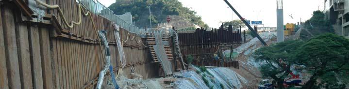
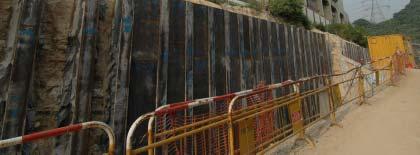
38 Construction of Earth-reinforced retaining wall, with a temporary sheet-pile wall as stage one set-back arrangement Buttress of wall


39 Detail of the precast panel as surface panel of the retaining wall


40 Detail seeing the tie behind the panel of the earth reinforced wall


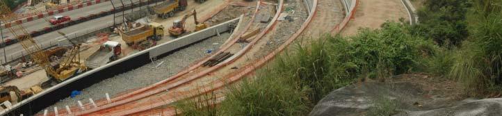
41 External view of some of the partially completed earth reinforced retaining wall


42 Other example of using earth reinforced wall to obtain extra space for a road widening project
43 Examples where large-scale slope works are required in construction 1. Building work obtaining of land space for building developemnt by land/site formation 2. Roadwork road or highway project including new projects, extension, widening or improvement works 3. Emergency/Major repair of slope, e.g. after serious land slide
44 Example of slope works for Building related project


45 Site formation to obtain a terraced land for the placing of a building - producing a retaining structure to support an adjacent structure


46 Sequence showing the forming of a multi-construction retaining wall using bore-pile and soldier-pile wall with in-situ concrete facing wall


47 Sequence showing the forming of a multi-construction retaining wall using bore-pile and soldier-pile wall with in-situ concrete facing wall


48 Diaphragm wall panel tie back using ground anchor Forming of a temporary vertical cut as part of the site formation work to acquire land for building construction project Festival Walk


49 Site formation producing a temporary slope as part of a building construction component CityU Academic Exchange Centre


50 Site formation producing a temporary slope as part of a building construction component South China Sport Association Extension


51 Site formation producing a temporary slope as part of a building construction component South China Sport Association Extension


52 Setting-back and stabilizing of a natural slope using buttress wall for a residential development project in Repulse Bay, Hong Kong
53 Example of slope works for Civil Engineering related project


54 Slope stabilization to form a new coastal roadway near Cyberport Buttress of wall

55 Buttress of wall


56 Slope setting back to give way for the passing of an elevated roadway for Route 8 near Butterfly Valley Buttress of wall


57 Stabilization of a vertical face as strengthening provision for a new roadway Buttress of wall

58
59 Forming a widened roadway along a strip of virgin land under Tai Po Road involving slope treatment/stabilization on both side of a valley


60 Cutting of large volume of slope to give way for the passing of a series of carriageway in Tai Wai, Shatin Original profile of slope being cut Buttress of wall Footing of wall
 Buttress")
61 Cutting into a surcharged slope to accommodate a series of column to support an elevated roadway (slope stabilized with sheet-pile wall tied back with anchor) Buttress of wall


62 Drilling machine to form the bore-hole for the anchor tendon Installing the soil anchor and tighten the skin wall with a row of waling beam


63 Cutting back of slope using bore-pile wall


64 Cutting back of slope using soldier pile wall


65 Cutting back of slope using in-situ RC retaining wall in plant-box design


66 Detail of the stepped planter-box type retaining wall Precast units for retaining wall facing panel with a surface drain channel


67 Construction wall


68 Preliminary treated slope with geo-textile and surface greening

69 Natural terrain Main Carriageway Reinforced fill embankment


70 Widening of roadway by obtaining land cut to the edge of a building

71 Widening of roadway by obtaining land cut to the edge of a building


72 Stage 1 cutting back of slope stabilized by ground anchors. Stage 2 permanent wall supported by using bored-piles.


73 Widening of existing roadway by cutting and afterward filling


74 Widening of existing roadway by cutting, temporary stabilizing and afterward filling


75 Widening of existing roadway by cutting, temporary stabilizing and afterward filling


76 Stabilizing large area of slope along a servicing roadway Tai Po Road to Shatin Future alignment of a new trunk road (Route 8)


77 Widening of Castle Peak Road near Sham Tseng Other examples of slope treatment or stabilization of more complex in nature


78 Other examples of slope treatment or stabilization of more complex in nature problem and method to collect and discharge storm water due to very large catchment area

79 Other examples of slope work or stabilization provision of more complex in nature complicated topographic condition and work layout Widening of Castle Peak Road near Sham Tseng
80 Maintenance of slope Conditions of a slope can be easily deteriorated within a certain period of time thus continual observation and maintenance should be carried out from time to time. In Hong Kong, the responsibility of slope maintenance are: For lands belong to the government by the government, responsible/managed by the Civil Engineering Department. For private lands owner of the land. Very often the exact responsibility for the maintenance of a slope is specified in some legal documents such as in the land lease. Detail information for the lease documents and records of the land owners can be obtained at the Government s Land Registry.
81 Maintenance Inspection (including slope and retaining walls) Inspection should be carried out regularly to determine the conditions of a slope. These inspections can be sub-divided into 3 levels/categories. 1. Routine inspection by non-professional person bases on some general visual guideline. 2. Engineer inspection by qualified geotechnical engineer according to some engineering indications and standards 3. Regular monitoring process by a quality engineering firm with special expertise and may involve the use of some monitoring devices or analysis
82 Routine Maintenance Inspection As a preliminary inspection to ensure the basic stability of a slope, routine inspection is recommended to carry out on a regular basis. The following elements should be observed during the inspection: 1. Ensure the slope surface and its drainage channels are free from debris. 2. Damaged or cracked protective surfaces and drainage system should be repaired and keep in good condition. 3. Unblock the weep holes and drains from time to time. 4. Remove over-grown vegetation that may crack the surface. 5. Observe any damage appears on the slope or other retaining structures 6. Observe any irregularity appears on or nearby the slope


83 Common condition of a slope
84 Typical Routine Maintenance Works for slopes and retaining walls
Topic: Site Formation
 Topic: Site Formation Presentation prepared by Raymond Wong February 2006 Purpose of site formation is to prepare a piece of land in order to: Accommodate building/s or other facilities which will be placed
MOA Project # Golden View Drive Intersection & Safety Upgrades
 Appropriate transitions can include extending the insulation beyond the roadway improvements, reducing the insulation thickness, or angling the insulation downward. Use of a frost tolerant section, an
Topic: Site Formation
 Topic: Site Formation Presentation prepared by Raymond Wong January 2010 Purpose of site formation is for: Forming of land by cutting & leveling of an uneven, sloppy or congested area. Accommodate building/s
Geoguide 6 The New Guide to Reinforced Fill Structure and Slope Design in Hong Kong
 Geoguide 6 The New Guide to Reinforced Fill Structure and Slope Design in Hong Kong Geotechnical Engineering Office Civil Engineering Department The Government of the Hong Kong Special Administrative Region
Design and Installation Guidelines for Retaining Walls. 1 P age. Geo Products, LLC 8615 Golden Spike Lane Houston, TX Phone:
 Design and Installation Guidelines for Retaining Walls 1 P age Geo Products, LLC 8615 Golden Spike Lane Houston, TX 77086 Phone: 281.820.5493 2011 Geo Products, Fax: 281.820.5499 LLC www.geoproducts.org
Highway Drainage 1- Storm Frequency and Runoff 1.1- Runoff Determination
 Highway Drainage Proper drainage is a very important consideration in design of a highway. Inadequate drainage facilities can lead to premature deterioration of the highway and the development of adverse
7. Draw an equipment set up for the production of a beam by post tensioning. 10. What are the common concrete structures which are produced by
 Construction Technology B (CON4313) Self Assessment Questions: Chapter 1 Prestressed Concrete 1. How does the prestressing of steel tendons in prestressed concrete offer a higher loading capacity than
Ohio Department of Transportation Division of Production Management Office of Geotechnical Engineering. Geotechnical Bulletin
 Ohio Department of Transportation Division of Production Management Office of Geotechnical Engineering Geotechnical Bulletin GB 2 SPECIAL BENCHING AND SIDEHILL EMBANKMENT FILLS Geotechnical Bulletin GB2
Case Studies on Soil Nailed Retaining Systems for Deep Excavations
 Indian Geotechnical Conference 2010, GEOtrendz December 16 18, 2010 IGS Mumbai Chapter & IIT Bombay Case Studies on Soil Nailed Retaining Systems for Deep Excavations Murthy, B.R. Srinivasa Professor e-mail:
Soil Mechanics Lateral Earth Pressures page Lateral Earth Pressures in case of inclined ground surface or friction at wall-ground interface
 Soil Mechanics Lateral Earth Pressures page 9 7.6 Lateral Earth Pressures in case of inclined ground surface or friction at wall-ground interface By now, we have considered the wall as perfectly smooth
INNOVATIVE SLOPE STABILISATION BY USING ISCHEBECK TITAN SOIL NAILS
 Dipl.-Wirt.Ing. Oliver Freudenreich Friedr. Ischebeck GmbH phone: ++49 2333 8305-0 Loher Str. 31 79 fax: ++49 2333 8305-55 e-mail: freudenreich@ischebeck.de D-58256 Ennepetal www.ischebeck.com INNOVATIVE
Volume 1. HOW TO MAKE A DREAM HOUSE EARTHQUAKE RESISTANT Contents
 Preparation of Seismic Design Manuals for Earthquake Disaster Mitigation Volume 1 HOW TO MAKE A DREAM HOUSE EARTHQUAKE RESISTANT Contents Part I: A house and its behavior during earthquake A House? How
Retaining Wall Design
 SIL 211 MEKANIKA TANAH Retaining Wall Design DR. IR. ERIZAL, MAGR DEPARTEMEN TEKNIK SIPIL DAN LINGKUNGAN FAKULTAS TEKNOLOGI PERTANIAN IPB 1 Conventional Retaining Walls Gravity Retaining Structures Stability
SCREW PILE APPLICATION SHEETS
 SCREW PILE APPLICATION SHEETS Advantages of screw piles Exceptionally fast installation rate up to 2... linear metres of pile installed per minute Load bearing capacities of over 300kN SWL Load bearing
Observed Earthquake Damage to Christchurch City Council Owned Retaining Walls and the Repair Solutions Developed
 Lessons learned from one of New Zealand s most challenging civil engineering projects: rebuilding the earthquake damaged pipes, roads, bridges and retaining walls in the city of Christchurch 2011-2016.
SPECIFICATIONS FOR PRECAST MODULAR BLOCK RETAINING WALL SYSTEM (revised 5/8/7)
") Page 1 of 7 STONE STRONG SYSTEMS SPECIFICATIONS FOR PRECAST MODULAR BLOCK RETAINING WALL SYSTEM (revised 5/8/7) PART 1: GENERAL 1.01 Description A. Work includes furnishing and installing precast modular
Page 1 of 7 STONE STRONG SYSTEMS SPECIFICATIONS FOR PRECAST MODULAR BLOCK RETAINING WALL SYSTEM (revised 5/8/7) PART 1: GENERAL 1.01 Description A. Work includes furnishing and installing precast modular
New techniques for stabilizing, amending and revegetating mine waste
 New techniques for stabilizing, amending and revegetating mine waste Including soil regeneration, erosion resistance and revegetation treatments in mined land remediation designs Vic Claassen Soils and
ENGINEERING DIRECTIVE
 Number: E-95-001 Date: 2/2/95 ENGINEERING DIRECTIVE Ross B. Dindio (Signature on Original) CHIEF ENGINEER The purpose of this engineering directive is to formally notify ALL Department engineering personnel
NPTEL Course GROUND IMPROVEMENT USING MICROPILES
 Lecture 22 NPTEL Course GROUND IMPROVEMENT USING MICROPILES Prof. G L Sivakumar Babu Department of Civil Engineering Indian Institute of Science Bangalore 560012 Email: gls@civil.iisc.ernet.in Contents
5-20 FOUNDATION REPORT/GEOTECHNICAL DESIGN
 5-20 FOUNDATION REPORT/GEOTECHNICAL DESIGN REPORT CHECKLIST FOR EARTH RETAINING SYSTEMS Introduction This checklist was developed to assist the geotechnical project professionals in preparing the Foundation
Geotechnical standards in Hong Kong
 Geotechnical standards in Hong Kong ACECC Workshop on Harmonization of Design Codes in Asian Region November 4, 2006, Taipei, Taiwan L. M. Mak President, Hong Kong Geotechnical Society (This paper has
AUGUST 2017 HASTINGS. retaining walls installation guide
 AUGUST 2017 HASTINGS retaining walls installation guide RETAINING WALL INSTALLATION GUIDE RETAINING WALL information Austral Masonry retaining wall blocks are an ideal choice for retaining walls in gardens,
Downloaded from Downloaded from /1
 PURWANCHAL UNIVERSITY VI SEMESTER FINAL EXAMINATION-2003 LEVEL : B. E. (Civil) SUBJECT: BEG359CI, Foundation Engineering. Full Marks: 80 TIME: 03:00 hrs Pass marks: 32 Candidates are required to give their
INTERLOCK BETWEEN PARTICLES AT EACH PERFORATION
 for Storm Water Management RUN OFF CONTROLS Porous Parking & Vehicle Access Cellular Confinement Systems (CCS) A Cellular Confinement System (CCS) is an engineered, expandable, polyethylene, honeycomb-like
Geotechnical Engineering Software GEO5
 Geotechnical Engineering Software GEO5 GEO5 software suite is designed to solve various geotechnical problems. The easy -to -use suite consists of individual programs with an unified and user-friendly
CIVIL BREADTH Exam Specifications
 NCEES Principles and Practice of Engineering Examination CIVIL BREADTH and STRUCTURAL DEPTH Exam Specifications Effective Beginning with the April 2015 Examinations The civil exam is a breadth and depth
Dry structural excavation is usually done with front-end loaders, bulldozers or backhoes.
 1.1 Excavation - General Excavation is the removal of all material (including ice, water, etc.) required for the construction of foundations or substructures as indicated on the drawings or as determined
GRASS-LINED CHANNEL (acre) CODE 840
 CODE 840") NATURAL RESOURCES CONSERVATION SERVICE ILLINOIS URBAN MANUAL PRACTICE STANDARD GRASS-LINED CHANNEL (acre) CODE 840 (Source: NC Erosion and Sediment Control Field Manual) DEFINITION A natural or constructed
NATURAL RESOURCES CONSERVATION SERVICE ILLINOIS URBAN MANUAL PRACTICE STANDARD GRASS-LINED CHANNEL (acre) CODE 840 (Source: NC Erosion and Sediment Control Field Manual) DEFINITION A natural or constructed
Modular Sediment Barriers (Instream)
") Modular Sediment Barriers (Instream) INSTREAM PRACTICES Flow Control No Channel Flow Dry Channels Erosion Control Low Channel Flows Shallow Water Sediment Control High Channel Flows Deep Water Symbol Photo
Modular Sediment Barriers (Instream) INSTREAM PRACTICES Flow Control No Channel Flow Dry Channels Erosion Control Low Channel Flows Shallow Water Sediment Control High Channel Flows Deep Water Symbol Photo
MSE WALLS CASE STUDIES. by John G. Delphia, P.E. TxDOT Bridge Division Geotechnical Branch
 MSE WALLS CASE STUDIES by John G. Delphia, P.E. TxDOT Bridge Division Geotechnical Branch COMMON RETAINING WALL TYPES CONCRETE BLOCK MSE TEMPORARY EARTH SPREAD FOOTING Gabions Drilled Shaft Soil Nail Tiedback
VOTR Site Assessment Victoria on the River
 i Executive Summary A. Introduction AECOM New Zealand Limited (AECOM) was engaged by Hamilton City Council (HCC) to undertake a geotechnical assessment of the (VOTR) site in Hamilton s central business
DESIGN OF RETAINING WALLS
 DESIGN OF RETAINING WALLS Dr. Izni Syahrizal bin Ibrahim Faculty of Civil Engineering Universiti Teknologi Malaysia Email: iznisyahrizal@utm.my Introduction Retaining wall is used to retain earth or other
Installation Manual. ArchCast Bridge. 3-Sided Precast Concrete Bridge Structure
 ArchCast Bridge 3-Sided Precast Concrete Bridge Structure Installation Manual Salem Location: 749 West Commercial Ave. Salem, IL 62881 (618) 548-1190 countymaterials.com Email: info@countymaterials.com
SPECIFICATION FOR REINFORCED SOIL WALL
 SPECIFICATION FOR REINFORCED SOIL WALL 1.0 EXTENT OF WORK The work shall consist of Reinforced Soil walls built in accordance with this specification and in conformity with the lines, levels and details
Large-scale site formation for a residential development at Sheung Shing Street, Ho Man Tin
 Large-scale site formation for a residential development at Sheung Shing Street, Ho Man Tin Presentation prepared by Raymond Wong, MCIOB Div. of Building Science & Technology, City University of Hong Kong
Chapter 18 EARTH RETAINING STRUCTURES
 Chapter 18 EARTH RETAINING STRUCTURES Final SCDOT GEOTECHNICAL DESIGN MANUAL June 2010 SCDOT Geotechnical Design Manual Earth Retaining Structures Table of Contents Section Page 18.1 Introduction...18-1
Lecture Retaining Wall Week 12
 Lecture Retaining Wall Week 12 Retaining walls which provide lateral support to earth fill embankment or any other form of material which they retain them in vertical position. These walls are also usually
Diaphragm wall Construction
 Diaphragm wall Construction Diaphragm wall is a continuous wall constructed in ground in to facilitate certain construction activities, such as: a) As a retaining wall b) As a cut-off provision to support
Training on Roads for Water and Resilience
 Training on Roads for Water and Resilience 1 DRAINAGE FROM UNPAVED ROADS Outline 3 1. 2. 3. 4. 5. 6. 7. Introduction Important considerations Drainage management Surface drainage features Subsurface drainage
Moll s Gap- Soil Nail Remediation of a Collapsed Retaining Wall Co. Kerry, Ireland
 Moll s Gap- Soil Nail Remediation of a Collapsed Retaining Wall Co. Kerry, Ireland Chris Bailey BSc (Hons) MSc CGeol FGS RoGEP Senior Engineering Geologist ATKINS 29 September 2017, TII Annual Conference,
RETAINING WALLS CHAPTER 13. Omitted parts: Section
 RETAINING WALLS CHAPTER 13 Omitted parts: Section 13.9 13.15-13.17 INTRODUCTION Retaining walls are structures that restrain soil or other materials at locations having an abrupt change in elevation. In
PART 3 - STANDARDS FOR SEWERAGE FACILITIES DESIGN OF STORM SEWERS
 PART 3 - STANDARDS FOR SEWERAGE FACILITIES 3.3 - DESIGN OF STORM SEWERS 3.301 Design of Storm Sewers A. General Information B. Investigations and Surveys C. Special Projects 3.302 Design Criteria for Storm
Temporary Structures. Excavations and Excavation Supports
 UNIVERSITY OF WASHINGTON DEPARTMENT OF CONSTRUCTION MANAGEMENT CM 420 TEMPORARY STRUCTURES Winter Quarter 2007 Professor Kamran M. Nemati Temporary Structures Excavations and Excavation Supports CM 420
LIQUID RUBBER INDUSTRIES ENGINEERING SPECIFICATIONS FOR ENGINEERS AND ARCHITECTS. Diagram 1: Standard Membrane Continuation 150 mm Overlap
 LIQUID RUBBER INDUSTRIES ENGINEERING SPECIFICATIONS FOR ENGINEERS AND ARCHITECTS Diagram 1: Standard Membrane Continuation 150 mm Overlap Ensure Membrane to Membrane Contact Diagram 2: Membrane Continuation
Performance of Mechanically Stabilized Earth walls over compressible soils
 Performance of Mechanically Stabilized Earth walls over compressible soils R.A. Bloomfield, A.F. Soliman and A. Abraham The Reinforced Earth Company, Vienna, Virginia, USA ABSTRACT: Two projects have recently
DRAINAGE & DESIGN OF DRAINAGE SYSTEM
 Drainage on Highways DRAINAGE & DESIGN OF DRAINAGE SYSTEM P. R.D. Fernando Chartered Engineer B.Sc.(Hons), M.Eng. C.Eng., MIE(SL) Drainage Requirement of Highway Drainage System Introduction Drainage means
Safety Assessment of Excavation with Fault Tree Analysis
 ISGSR2007 First International Symposium on Geotechnical Safety & Risk Oct. 18~19, 2007 Shanghai Tongji University, China Safety Assessment of Excavation with Fault Tree Analysis L. Z. Chen Shanghai Jiao
Lecture 7 BALLAST & SUBGRADE. Dr. Charisma Choudhury. April 2011
 Transportation Engineering II: Highway Design & Railways Lecture 7 BALLAST & SUBGRADE Dr. Charisma Choudhury April 2011 Ballast Functions Provide a hard and level bed for sleepers Hold sleepers in place
PART 1 GENERAL REQUIREMENTS
 PART 1 GENERAL REQUIREMENTS Contract Closeout Plan 110 Arrow diagram for project close-out...3 Erosion Control 121 Straw bale barrier... 5 122 Silt fence... 7 123 Diversion dike... 9 124 Inlet protection...
SECTION EXCAVATION AND EMBANKMENT. B. Subbase Grading A samples for gradation analysis.
 PART 1 GENERAL 1.1 DESCRIPTION A. The WORK under this Section includes providing all labor, materials, tools and equipment necessary for excavation and embankment construction to the lines, grades and
Geotechnical problems on historic buildings consolidation
 Geotechnical problems on historic buildings consolidation Ph. D. St. Nicoleta Maria ILIEŞ Faculty of Civil Enigineering and Building Services Technical University of Cluj Napoca, Romania 1. Considerations
DIVISION 3 PAVEMENT (FLEXIBLE AND RIGID) CONSTRUCTION SPECIFICATIONS
 CONSTRUCTION SPECIFICATIONS") OPS GENERAL CONDITIONS OF CONTRACT NOV 2006 General Conditions of Contract DIVISION 1 GENERAL S OCT 92 102 Weighing of Materials NOV 2004 106 Electrical Work NOV 2003 120 The Use of Explosives APR 2006
OPS GENERAL CONDITIONS OF CONTRACT NOV 2006 General Conditions of Contract DIVISION 1 GENERAL S OCT 92 102 Weighing of Materials NOV 2004 106 Electrical Work NOV 2003 120 The Use of Explosives APR 2006
Infiltration Guidelines
 Appendix E Infiltration Guidelines As a stormwater management method, infiltration means retaining or detaining water within soils to reduce runoff. Infiltration can be a cost-effective method to manage
Anchor bolts ASTM F1554, Gr. 36 Wide flange beams ASTM A992, Fy = 50 ksi Misc. structural steel ASTM A36, Fy = 36 ksi
 STRUCTURAL NOTES MATERIAL STRENGTHS Structural Steel Reinforcing Steel Concrete Masonry Structural Lumber Anchor bolts ASTM F1554, Gr. 36 Wide flange beams ASTM A992, Fy = 50 ksi Misc. structural steel
Structural Tests and Special Inspections Form. Inspection of Fabricators (1704.2)
") Inspection of Fabricators (1704.2) Furnish inspection reports (1704.2.1) - Fabricators that have not been approved Provide a Certificate of Compliance (1704.2.2) - Approved Fabricators Steel Construction
Inspection of Fabricators (1704.2) Furnish inspection reports (1704.2.1) - Fabricators that have not been approved Provide a Certificate of Compliance (1704.2.2) - Approved Fabricators Steel Construction
ICC-ES Evaluation Report Issued July 1, 2011 This report is subject to renewal in one year.
 ICC-ES Evaluation Report ESR-1959 Issued July 1, 2011 This report is subject to renewal in one year. www.icc-es.org (800) 423-6587 (562) 699-0543 A Subsidiary of the International Code Council DIVISION:
Standards for Soil Erosion and Sediment Control in New Jersey May 2012 STANDARD FOR SLOPE PROTECTION STRUCTURES. Definition
 STANDARD FOR SLOPE PROTECTION STRUCTURES Definition Structures to safely conduct surface runoff from the top of a slope to the bottom of the slope. Purpose The purpose of this practice is to convey storm
Case History: Value Engineering of Driven H-Piles for Slope Stability on the Missouri River
 DEEP FOUNDATIONS 207 Case History: Value Engineering of Driven H-Piles for Slope Stability on the Missouri River W. Robert Thompson, III, 1 M.ASCE, P.E., Jeffrey R. Hill, 2 M.ASCE, P.E., and J. Erik Loehr,
A Case Study: Foundation Design in Liquefiable Site
 RESEARCH ARTICLE OPEN ACCESS A Case Study: Foundation Design in Liquefiable Site Tahar Ayadat* *(Department of Civil Engineering, College of Engineering, PMU University, P.O. Box 1664, Al-Khobar, 31952,
DESIGN AND DETAILING OF RETAINING WALLS
 DESIGN AND DETAILING OF RETAINING WALLS (For class held from nd April 07) Dr. M. C. Nataraja, Professor, Civil Engineering Department, Sri Jayachamarajendra Collge of Engineering, Mysore-5a70 006 Phone:
BANJO BILL ROCK CATCHMENT BASINS
 ABSTRACT BANJO BILL ROCK CATCHMENT BASINS Paul B. Groneck, P.E. Vice President & Tom Armour, P.E. President DBM Contractors, Inc. P.O. Box 6139, Federal Way, WA 98063, U.S.A. Email paulg@dbmcm.com tarmour@dbmcm.com
ARCHITECTURAL DRAWINGS
 PROJECT DETAILS Implementation Partner: Project title: Grant No.: KIS062 Content : ARCHITECTURAL DRAWINGS SHEET NO. REHABILITATION OF GRANT NO.: - KIS062 COVER SHEET INDEX SHEET CONTENTS 01 02 03 04 05
TECHNICAL CONTENT PROPOSED STEEP SLOPE REGULATION
 1 TECHNICAL CONTENT PROPOSED STEEP SLOPE REGULATION Draft 2/08/10 (Revised 02-14-11,Revised 02-21-11, Revised 03-03-11, Revised 04-19-11, Revised 04-20-11, Revised 05-05-11, Revised 05-09-11). DEFINITIONS
Solving Slope Protection Problems Geoweb Cellular Confinement System
 Solving Slope Protection Problems Geoweb Cellular Confinement System Leaders In Advanced Geotechnology TM Slope Protection An Engineered Framework for Slope Protection The Presto Geoweb Cellular Confinement
4.6 Procedures for Connections
 4.6 Procedures for Connections This section provides Tier 2 evaluation procedures that apply to structural connections: anchorage for normal forces, shear transfer, vertical components, interconnection
SECTION SPECIFICATION FOR STONEBRIDGE RETAINING WALL SYSTEM
 SECTION 32 32 23 SPECIFICATION FOR STONEBRIDGE RETAINING WALL SYSTEM PART 1: GENERAL 1.01 Scope Work includes furnishing all materials, labor, equipment, and supervision to install a Stonebridge segmental
BISON PRECAST FLOORING SPECIFICATION
 BISON PRECAST FLOORING SPECIFICATION 1.0 SCOPE OF THE SPECIFICATION 1.01 Relates to: This specification covers the design, manufacture and associated site work of the following types of floors:- Hollowcore
RIGID INCLUSIONS. Rigid Inclusions offer an economical approach for building on sites underlain by soft soil.
 H A Y W A R D B A K E R I N C. RIGID INCLUSIONS Rigid Inclusions offer an economical approach for building on sites underlain by soft soil. Above: HBI installed Rigid Inclusions on a congested downtown
CF50/100 KW TURBINE ACCESS ROAD, CRANE PLATFORM, CONCRETE, AND LIFTING SPECIFICATIONS C&F GREEN ENERGY REVISION PREPARED BY APPROVED BY DATE
 CF50/100 KW TURBINE ACCESS ROAD, CRANE PLATFORM, CONCRETE, AND LIFTING SPECIFICATIONS C&F GREEN ENERGY REVISION PREPARED BY APPROVED BY DATE 001 First Draft W Hession 12.02.2014 Introduction This document
Brush layering construction
 Brush layering construction Brush layering consists of embedding live branches on successive horizontal rows along contours on the face of a slope. Rooted plants can also be placed among the live branches.
Chapter A-8 GEOTECHNICAL ANALYSIS FAIRFAX-JERSEY CREEK (JERSEY CREEK SHEET PILE WALL)
") Kansas Citys, Missouri and Kansas Flood Damage Reduction Feasibility Study (Section 216 Review of Completed Civil Works Projects) Engineering Appendix to the Interim Feasibility Report Chapter A-8 GEOTECHNICAL
Kansas Citys, Missouri and Kansas Flood Damage Reduction Feasibility Study (Section 216 Review of Completed Civil Works Projects) Engineering Appendix to the Interim Feasibility Report Chapter A-8 GEOTECHNICAL
G R A V I T Y / G E O G R I D
 GRAVITY/GEOGRID MAGNUMSTONE Overview note: bolded terms are defined in our online glossary at www.cornerstonewallsolutions.com The MagnumStone retaining wall system was developed with the installer in
Greenleaf Urban tree and landscape products. Turf reinforcement module for porous vehicular surfaces
 Greenleaf Urban tree and landscape products Turf reinforcement module for porous vehicular surfaces Why Grassrings? 90% grass root development area 100% grass cover Grass roots Grass roots free to grow
Installation Information 2016
 Installation Information 2016 DENDRO-SCOTT Root Barrier... why use anything else? DENDRO-SCOTT Root Barrier, recognised by the Environment Agency, is known for its quality and reliability. It is flexible
DBM Contractors, Inc. Donald B. Murphy Contractors, Inc. 60 Years of Innovation and Customer Satisfaction
 Donald B. Murphy Contractors, Inc. 60 Years of Innovation and Customer Satisfaction Dewatering Ground Improvement Slope Stabilization Foundation Support Earth Retention Design/Build Design/Build for cost-effective
Storm Drain Inlet Protection
 Categories EC Erosion Control SE Sediment Control TC Tracking Control WE Wind Erosion Control Non-Stormwater NS Management Control Waste Management and WM Materials Pollution Control Legend: Primary Category
10.1 INTRODUCTION 10.1 DRAINAGE
 CHAPTER 10 DRAINAGE 10.1 INTRODUCTION The drainage system manages both surface and subsurface water coming off the road surface and from the surrounding countryside. The purpose of the system is to ensure
1.364 ADVANCED GEOTECHNICAL ENGINEERING HOMEWORK No. 5
 .364 ADVANCED GEOTECHNICAL ENGINEERING HOMEWORK No. Due: Friday December 2. This question concerns the stability of an open slope cutting that will be used to provide construction access for a 3.2m deep
Flood Hazard Assessment Report Falls Gulch, Larimer County, Colorado January 16, 2013
 United States Department of Agriculture Natural Resources Conservation Service Denver Federal Center Building 56, Room 2604 P.O. Box 25426 Denver, CO 80225 720-544-2818-OFFICE alton.albin@co.usda.gov Flood
VERTI-BLOCK - DESIGN MANUAL
 Company Information General Information Verti-Block is the latest innovative forming system from Verti-Crete, LLC. Recognized worldwide for outstanding aesthetics and performance, Verti-Crete s proprietary
File No Supplemental November Geotechnical and Environmental Consulting Engineers
 Supplemental Information & Geotechnical Recommendations Proposed New Solar Valley Location B (East of Building No. 7) Cañada Community College 4200 Farm Hill Boulevard Submitted to: Mr. Peter Hempel Construction
Matrix Helical Anchoring System
 Matrix Helical Anchoring System INNOVATIVE SOLUTIONS FOR PROFESSIONAL MASONRY REINFORCEMENT The uses of Matrix Remedial Ties and Matrix Crack Stitching Bar are both wide and varied and they can be utilised
Mr. Paul Dunlap, California Department of Water Resources
 Memorandum To: From: Mr. Paul Dunlap, California Department of Water Resources Oroville Dam Spillway Incident Independent Forensic Team Date: September 5, 2017 Re: Interim Status Memorandum Introduction
CE 6012 Ground Improvement Techniques Question Bank
 CE 6012 Ground Improvement Techniques Question Bank Unit I INTRODUCTION Role of ground improvement in foundation engineering - methods of ground improvement Geotechnical problems in alluvial, laterite
Design Illustrations on the Use of Soil Nails to Upgrade Loose Fill Slopes
 Design Illustrations on the Use of Soil Nails to Upgrade Loose Fill Slopes Geotechnical Engineering Office and The Hong Kong Institution of Engineers (Geotechnical Division) November 2013 2 Disclaimer
highways, drainage, runoff, surface, sub-surface, systems Carrier pipe
 SCI LECTURE PAPERS SERIES HIGHWAY DRAINAGE SYSTEMS Santi V Santhalingam Highways Agency, Room 4/41, St. Christopher House Southwark Street, London SE1 0TE Telephone +44 (0) 171 921 4954 Fax +44 (0) 171
DESIGNING AND CONSTRUCTION OF T-WALL RETAINING WALL SYSTEM
 Istanbul Bridge Conference August 11-13, 2014 Istanbul, Turkey DESIGNING AND CONSTRUCTION OF T-WALL RETAINING WALL SYSTEM T. C. NEEL and K.BOZKURT ABSTRACT This work shall consist of the design, manufacture
PERVIOUS PAVEMENT. Alternative Names: Permeable Pavement, Porous Concrete, Porous Pavers
 4.1-a PERVIOUS PAVEMENT Alternative Names: Permeable Pavement, Porous Concrete, Porous Pavers DESCRIPTION Pervious pavement is any system comprised of a load bearing surface that allows for movement of
SPECIAL PROVISIONS - SP2014 BOOK Page 1 October 8, 2013
 SPECIAL PROVISIONS - SP2014 BOOK Page 1 S-1 (2104) REMOVE AND REPLACE BITUMINOUS PAVEMENT (ADA) Always include SP2014-119 (PLANT MIXED ASPHALT PAVEMENT) or SP2014-121 (PLANT MIXED ASPHALT PAVEMENT FOR
Hollowcore Floors. The ideal structural floor solution for all building types in all sectors.
 Hollowcore Floors Hollowcore Floors The ideal structural floor solution for all building types in all sectors. 2 3 System Overview Prestressed hollowcore units form part of the comprehensive range of precast
1/26/2015 DETAILS CIP DETAIL EXAMPLES WHY SIMPLIFY DETAILS? CIP DETAIL EXAMPLES DETAILING FOR SIMPLICITY
 Detailing of ABC Bridges for Simplicity and Durability Michael P. Culmo, P.E. CME Associates, Inc. East Hartford, CT DETAILS This presentation contains many preferred details My favorite details will be
GeoEng2000 An International Conference on Geotechnical & Geological Engineering
 GeoEng2000 An International Conference on Geotechnical & Geological Engineering 19-24 November 2000 Melbourne Exhibition and Convention Centre Melbourne, Australia Barrettes : A versatile foundation for
UNDERPINNING A CRANE FOUNDATION
 UNDERPINNING A CRANE FOUNDATION Donald R. McMahon, P.E., McMahon & Mann Consulting Engineers, P.C., Buffalo, New York, USA Andrew J. Nichols, P.E., McMahon & Mann Consulting Engineers, P.C., Buffalo, New
E. STORMWATER MANAGEMENT
 E. STORMWATER MANAGEMENT 1. Existing Conditions The Project Site is located within the Lower Hudson Watershed. According to the New York State Department of Environmental Conservation (NYSDEC), Lower Hudson
Geotechnical Investigation Reports and Foundation Recommendations -Present status in India -Examples
 Geotechnical Investigation Reports and Foundation Recommendations -Present status in India -Examples Prof. V.S.Raju (Formerly: Director, IIT Delhi & Professor and Dean, IIT Madras) Email: rajuvs_b@yahoo.com
Anchorplex retaining wall construction guide. Building. Anchorplex. Retaining Wall Systems
 Anchorplex retaining wall construction guide Building Anchorplex Retaining Wall Systems Table of Contents and ow to Use This Guide table of contents ow to Use This Guide. 2 About the Anchorplex System.
SLAB ON GRADE Insul-Joint or Expansion Joint Material as Required by A/E Specifications AquaCheck Liquid Coating 400 (Waterproofing Membrane) with Aqu
 with Aqu") INSTALLATION INSTRUCTIONS Note: The following installation instructions are based off of ASTM E 1643 (Standard Practice for Installation of Water Vapor Retarders Used in Contact with Earth or Granular
INSTALLATION INSTRUCTIONS Note: The following installation instructions are based off of ASTM E 1643 (Standard Practice for Installation of Water Vapor Retarders Used in Contact with Earth or Granular
The Aizhai Suspension Bridge is
 INTERNATIONAL DESIGN & CONSTRUCTION: BRIDGES Mountain grown Hilly terrain contributes mightily to China bridge By Yinbo Liu, Ph.D., P.E., Guoping Chen, Shulong He and Yongjian Zhang, Ph.D. Contributing
Confined masonry. Definition
 Lesson prepared by the Swiss Agency for Development and Cooperation for the trainings at the Housing Reconstruction Centres Ballakot and Battagram 13 August 2006 1 Definition Confined Masonry is a construction