CLIC Civil Engineering, Infrastructure and Siting Working Group, (CEIS) John Osborne Matthew Stuart CERN SMB-SE-FAS
|
|
|
- Angelica Grant
- 6 years ago
- Views:
Transcription
 John Osborne Matthew Stuart CERN SMB-SE-FAS")
1 CLIC Civil Engineering, Infrastructure and Siting Working Group, (CEIS) John Osborne Matthew Stuart CERN SMB-SE-FAS 1
2 CEIS Working Group Civil Engineering, Infrastructure and Siting Core Disciplines: Civil Engineering and Chair J.Osborne Technical Secretary M.Stuart CE Fellow started 1 st March 17 CLIC Link Persons S.Stapnes/D.Schulte/C.Rossi/R.Corsini Cooling and Ventilation CV M.Nonis + Fellow/PJA Electricity EL N.Bellegarde/D.Bozzini Survey SU H.Mainaud Durand Transport & Handling HE I.Ruehl Interaction Region K.Elsener Logistics/lab readiness M. Tiirakari CE Layouts and cross-sections SMB/Civil Engineering Design Office HSE Link Person S.Marsh Schedule K.Foraz ILC Link Persons J.Osborne/A.Yamamoto 2
3 Mandate for the CLIC Civil Engineering & Infrastructure and Siting (CEIS) Working Group General Objective Develop the existing layouts for the project from a civil engineering and technical infrastructure point of view, and work with the various actors towards a realistic design and project planning as needed for the CLIC Implementation Plan, due Specific responsibilities: Develop new and/or update civil engineering layouts for 380GeV, 1.5TeV and 3TeV machine. Develop new civil engineering layout for 380GeV machine using Klystron technology. Update the tunnel design and layout to accommodate the machine (e.g. ventilation, electricity, survey, controls, safety and handling equipment). Develop a layout for the interaction region. Study environmental aspects of the project and siting preparation. Work together with ILC on areas of synergy. Produce schedule and cost estimates. Consider and update transport, installation and CERN logistics issues for the project. Technical infrastructure and installation scheduling. This group will report to the CLIC Accelerator Steering Committee. Regular meetings are planned for approximately every 6 weeks. Provisional slot is Friday mornings from 9am until 11am. Initial Kick-off meeting took place on Friday 31 March Ad-hoc meetings as needed on dedicated subjects. Additional experts will be contacted as needed. 3

4 CDR Updated Plans and Layouts Comments: Most important drawing for costing Tunnel length includes all tunnels (main tunnel, turnarounds etc ) Site length is the amount of land needed to build CLIC Colour Code: 380 GeV Dark Red 1.5 TeV Pink 3 TeV Light Pink BDS Light Blue section. Injection Complex - Green 4

5 CDR Updated Plans and Layouts Long profile from CDR updated for new energy stages: Laser straight tunnels (unlike horizontal tunnel for ILC) 3 TeV 1.5 TeV 380 GeV Tunnel was rotated to reduce depths Tunnel passes through the Gland depression i.e. same depth as ILC RDR 3TeV machine enters into Limestone rock Water transfer tunnel from lake has been removed 5
6 CDR Updated Plans and Layouts Plan The second detector hall has been removed. Only one shielding wall now required. A new service cavern has been added and includes a 12m diameter shaft Section Assembly and testing hall required for the detector. 6
7 Turnaround Region Plan Turnaround Plan: Turnaround region every 878m The size of the facility cavern has increased significantly to host power converter/cv/ EL equipment The lengths of the turnaround loops may need to be increased. 7

8 Injector Complex Layout Injection Complex Layout: 2.5km drive beam injector building, feasibility study required for transport options within the building. 2500mx30mx9m building the full area of this building is only required for the 3 TeV energy stage. 8

9 Drive Beam Injector Since the CDR, RF power distribution has been moved out of the 2.5km Klystron and Modulator building: Approximately 10,000m 2 of building space required for 6 substations highlighted below. 9
10 Drive Beam Injector Section A-A: For 380 GeV a reduced building cross section has been shown: Minimum width possible for reduced cross section is 17m. 10
11 Drive Beam Injector Section A-A: For 380 GeV a reduced building cross section has been shown: Extension of a further 15m will be required for upgrades. 11
12 Drive Beam Injector Section A-A: For 380 GeV a reduced building cross section has been shown: Increased Material and installation costs Two cranes will be required for future upgrades (transport options still being studied). 12

13 Drive Beam Injector Section A-A: For 380 GeV a reduced building cross section has been shown: Initial cost saving due to decreased surface building size by approx. 40% 13
14 Shaft Layout CDR Shaft Layout: Expected to change a second lift required. Current shafts are 9m in diameter. The depth of the shafts are expected to be less than 300m. 14
15 M Fire Safety and ventilation Fire doors seal off the section on fire and the two adjacent sectors. M M M Each sector of tunnel shall be a fire compartment with a capable fire resistance of at least 2 hours. Positive pressurization from the ventilation system in adjacent sectors to contrast the smoke pressure. 15

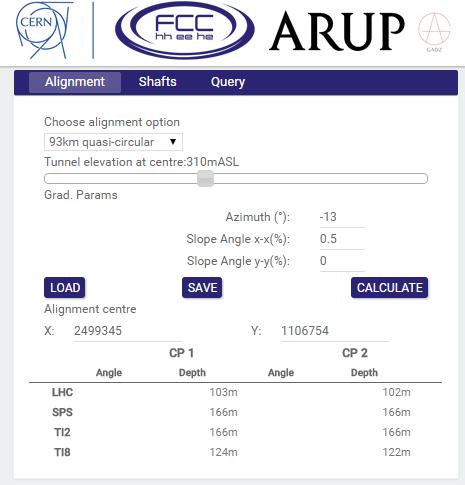
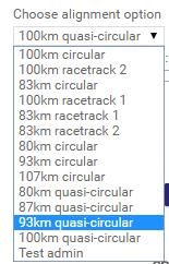
16 CLIC-Tunnel Optimisation Tool CLIC TOT will allow us to optimise the position, depth, and angle of the tunnels. Using a separate layer CLIC TOT will enable us to optimise the position of the surface Injection complex and relate this to the position of the main tunnel. User inputs and Geological data requirements are to be refined to understand the potential for a machine learning tool that can be used to automatically optimise the position of CLIC based on the user inputs. 16
17 Data & Functionality Prioritisation Datasets: Rotation of the machine tunnel in both the vertical and horizontal plane in 0.1 degree increments. Task 1 Establish Project Setup and Technical Basis June (mid) Task 2 Data and Functionality Prioritisation June (end) A max gradient of 6%. Task 3 Specifications and TOT-CLIC architecting/wireframing July (mid) Adjustable shaft locations Aiming for one shaft per 5km. A maximum shaft depth of 300m inclined tunnels a possibility if required. Central injection complex input as a separate file. (Concept Stage) Task 4 Data Integration and TOT-CLIC (beta) development July (mid) Task 5 Finalised TOT-CLIC Development Sept (end) Task 6 Troubleshooting and Technical Support - 17

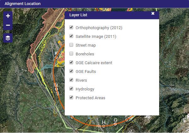
18 CLIC Study Boundary Study Area Position of CLIC between the Jura and Lake Geneva Jura mountain range. Lake Geneva 18

19 CLIC Study Boundary Study Area CLIC straddles the France Switzerland border Potential to keep the first energy stage in France. Lake Geneva Border: Dotted red line. 19

20 CLIC Study Boundary Study Area Two depressions containing complex moraines Gland and Allondon. Could be avoided at lower energy stage. Allondon Gland 20


21 BIM Tunnel Optimisation Tool (FCC) Streamlines the conventional approach which is broadly linear and manual Max value extracted from early project data Single Source of Data Visual decision aid Clash detection Regional Scale Iterative process and comparison of options 21

22 Feasibility Study Hydrology Lake Geneva The Rhone L Arve River Aquifers 22

23 Environmental Considerations Nature reserves Protected wetlands Areas of biological importance 23

24 Buildings 24


25 Geothermal Boreholes Water supply pipelines Geothermal drillings 25

26 User interface Input Parameters 26

27 User interface Input Parameters 27

28 User Interface Alignment Profile 28

29 User Interface - Outputs 29

30 CERN/KEK Collaboration to develop TOT for ILC Optimisation Many new features added to the tool that can be utilised in CLIC TOT, such as : IP position can be changed. LINAC Rotation/Flip Inclined Access tunnels 30


31 FCC Cross Section Development Previously updated Large 6.8m tunnel. Transport tunnel located beneath false floor. Increased dimensions of machine components. Original 6m cross sectional design. Two compartments separated by fire protection wall. Small emergency air extraction 31
32 FCC Cross Section Development New FCC Layout. Extraction located above false ceiling. 32
33 FCC Cross Section Development New FCC Layout. Air intake located below false floor. 33
34 FCC Cross Section Development New FCC Layout. Machine dimension reduced from 1500mm to 1480mm. 34
35 FCC Cross Section Development New FCC Layout. Fire doors section off the tunnel at specified intervals. 35

36 FCC Cross Section Development New FCC Layout. Extraction located above false ceiling. Air intake located below false floor. Fire doors section off the tunnel at specified intervals. Can these concepts be considered for CLIC? 36
 9.9m Backfill from tunnel excavation to be utilised.")
37 Klystron Single Tunnel - TBM Extraction located above false ceiling 2.6m 2 1.5m TBM Tunnel 10m TBM required to achieve required surface width within tunnel. 3.2m A lot of space below the floor potential to have a services located here. (see example for Tunnel Mont-Sion) 9.9m Backfill from tunnel excavation to be utilised. (see example for Tunnel Mont-Sion) Backfill around Service tunnel Access to be provided at regular intervals 37

38 Mont-Sion Tunnel (Autoroute, Geneva to Annecy) TBM Tunnel Slightly larger than the CLIC tunnel at a diameter of 12m The example shows the utilisation of space below the road level in Mont-Sion tunnel a similar thing could be done for a single TBM tunnel at the Klystron 380 GeV energy stage. 38

39 Klystron Single Tunnel - Roadheaders Roadheader Tunnel Single tunnel layout 10m width, similar to the ILC potential for the same space reductions as the TBM tunnel. Crane requirements for klystron module cavern to be determined? What services will be required? (Machine Design is for presentation purposes only and is subject to change) 39


40 Klystron Single Tunnel - Roadheaders ILC CLIC Comparison (Machine Design is for presentation purposes only and is subject to change) 40

41 Klystron Single Tunnel - Roadheaders Roadheader Tunnel Must be compatible with TBM drive beam upgrades. 41

42 Drive Beam Option Main Tunnel Cross Section Main tunnel cross section: Cross section was increased from 4.5m to 5.6m 5.6m is the standard size for European subways Power converter community requested a lot more space => increase diameter of tunnel CV pipes in slab are now isolated from machine by a compressible filler Cable trays are not individually labelled for now Transversal Ventilation no longer compatible with current heat loads. 42

43 Cooling and Ventilation Ventilation schemes: Original concept was a transversal ventilation system as shown. Extremely high air flow rate required to cool down the modules. Current numbers are much higher with respect to the CDR! CDR numbers omitted the heat loads of the RF components to air (Accelerating structures + RF-loads and PETS W/m) Feasibility study for local Cooling system is to be undertaken. 43

44 Cooling and Ventilation Heat Loads Heat load to air (worst case at one beam): 380 GeV: W 472.7W/m 3 TeV: 11,469,708W 537.9W/m Heat Load to water (worst case at one beam): 380 GeV: 8,148,798W 3 TeV: 57,258,415W 44
45 Summary 380GeV, 1.5TeV and 3TeV machine layouts to be created. Develop new engineering layouts for the 380 GeV Klystron Machine both single and double tunnel layouts 380 GeV Klystron design compatible with energy upgrades. Double tunnel or single tunnel required. New Tunnel Optimisation Tool to be developed specifically for CLIC. Civil Drawings are to be produced by Civil Draughtsmen - new drawings to be produced for the Klystron design and existing drive beam design drawings to be changed. A detailed cost estimate for infrastructure to be produced and work together with ILC on areas of synergy. We are looking forward to the ILC AAA visit at CERN on the 12/13 th July
46 Thank You For Your Attention Thank you to all contributors 46
ILC ASIAN DRAFT SCHEDULE
 ILC ASIAN DRAFT SCHEDULE K Foraz, M Gastal & J Osborne Many thanks to all contributors Objectives and scope To provide a target baseline construction schedule for the 2 Asian sample sites Address remarks
https://edms.cern.ch/document/ /1
 https://edms.cern.ch/document/1761678/1 Civil engineering aspects and challenges for CERN s Future Accelerators (100km Future Circular Collider / Linear Colliders and High Luminosity LHC) Introduction
ST IMPLICATIONS IN THE CNGS PROJECT
 EUROPEAN ORGANIZATION FOR NUCLEAR RESEARCH ORGANISATION EUROPÉENNE POUR LA RECHERCHE NUCLÉAIRE CERN - ST Division CERN-ST-2000-012 February, 2000 ST IMPLICATIONS IN THE CNGS PROJECT M. Wilhelmsson Abstract
EUROPEAN ORGANIZATION FOR NUCLEAR RESEARCH European Laboratory for Particle Physics CERN TS DEPARTMENT
 EUROPEAN ORGANIZATION FOR NUCLEAR RESEARCH European Laboratory for Particle Physics CERN TS DEPARTMENT EDMS Nr. 480988 CERN-TS-2004-017 (IC) Scheduling the installation of the LHC injection lines L. Lari,
Report from the GDE director. Barry Barish Snowmass 14-Aug-05
 Report from the GDE director Barry Barish Snowmass 14-Aug-05 Global Design Effort The Mission of the GDE Produce a design for the ILC that includes a detailed design concept, performance assessments, reliable
Finnish Underground Lab
 Finnish Underground Lab Juha Peltoniemi Centre for Underground Physics in Pyhäsalmi University of Oulu cupp.oulu.fi Location of the Pyhäsalmi site Pyhäsalmi mine in Pyhäjärvi town Connections Roads open
A Member of the Constructor Group STORAGE MACHINES. Increase efficiency and organisation in your warehouse
 A Member of the Constructor Group STORAGE MACHINES Increase efficiency and organisation in your warehouse Increase productivity with Dexion automated storage DEXION offers computer-controlled storage and
3D Layout Navigator. The world s first 3D positioning system designed specifically for construction layout.
 LN-100 3D Layout Navigator The world s first 3D positioning system designed specifically for construction layout. The first time you see it you know it s unlike anything you ve seen before. Its clean,
Radiation Environment and Shielding Design Optimization at MEIC
 Radiation Environment and Shielding Design Optimization at MEIC Pavel Degtiarenko Radiation Physics Group Radiation Control Department, JLab October, 2015 Contents Brief review of MEIC Radiation Protection
Finnish Underground Lab
 Finnish Underground Lab Juha Peltoniemi Centre for Underground Physics in Pyhäsalmi University of Oulu cupp.oulu.fi The CUPP project CUPP Centre for Underground Physics in Pyhäsalmi The purpose is to establish
Geothermal Tunnel Linings. Principles of Geothermal Tunnel Linings
 Geothermal Tunnel Linings Principles of Geothermal Tunnel Linings Duncan Nicholson - Director, Ove Arup and Partners Limited 11.00 11.30hrs 18 October 2012 Contents Background Ground source heat energy
Box Culverts. Easy to install, suitable for very shallow or deep fill, ideal for use in a wide variety of civil engineering applications.
 Box Culverts Box Culverts Easy to install, suitable for very shallow or deep fill, ideal for use in a wide variety of civil engineering applications. 2 3 System Overview Forterra is one of the largest
An indicative program for works to be conducted within the Sydney Park construction compound is provided in Table 6-20.
 The land required for the Sydney Park construction compound would be used temporarily throughout construction only. The construction compound site would be rehabilitated at the completion of construction,
Stainless steel. 1.6 Stainless steel IP 69 K. Premium Panel, protection category IP 69K
 T Premium Panel, protection category IP 69K IP 69 K.6 H H H Optionally with or without keyboard housing Resistant to high-pressure cleaning (protection category IP 69K). The seal lies between two surfaces
Created by Simpo PDF Creator Pro (unregistered version) Asst.Prof.Dr. Jaafar S. Maatooq
 Asst.Prof.Dr. Jaafar S. Maatooq") Lect.No.9 2 nd Semester Barrages, Regulators, Dams 1 of 15 In order to harness the water potential of a river optimally, it is necessary to construct two types of hydraulic structures, as shown in Figure
Lect.No.9 2 nd Semester Barrages, Regulators, Dams 1 of 15 In order to harness the water potential of a river optimally, it is necessary to construct two types of hydraulic structures, as shown in Figure
Guy Crockford, BE/OP/LHC, CERN
 Automation in the SPS and LHC and its effect on operator skills The past 20 years have seen great advances in the CERN accelerator control systems. Low level operation skills have been largely replaced
NGWA s Water Well Construction Standard: ANSI/NGWA 01-14
 NGWA s Water Well Construction Standard: ANSI/NGWA 01-14 NGWA Standard Development Process as Approved by ANSI What is ANSI? The American National Standards Institute (ANSI), founded in 1918, promotes
Funding was provided by the City of New York via the Hudson Yards Infrastructure Corporation and Hudson Yards Development Corporation.
 FACT SHEET GENERAL INFORMATION The project extends the existing No.7 Line subway service via a 1.5 mile extension from Times Square to the new 34 Street Hudson Yards station located at West 34th Street
Status of MedAustron
 Status of MedAustron Project goals, design, parameters Status und schedule Michael Benedikt CERN, BE-Department Symposium Verein AUSTRON Vienna, 15. March 2011 Goals of the MedAustron project Construction
llilliiiillllllllilllllllllllllllllllllllil CERN AT, (CR, 94'36
 EUROPEAN ORGANIZATION FOR NUCLEAR RESEARCH CERN LIBRARIES, GENEVA llilliiiillllllllilllllllllllllllllllllllil CERN AT, (CR, 94'36 QERN-AT-94-36 ;.t W4?. Four 12 kw/4.5 K Cryoplants at CERN S. Claudet,
UNDERGROUND CHARACTERISATION AND RESEARCH FACILITY ONKALO ANTTI IKONEN, MIA YLÄ-MELLA, TIMO ÄIKÄS POSIVA Oy Olkiluoto, Finland
 UNDERGROUND CHARACTERISATION AND RESEARCH FACILITY ONKALO ANTTI IKONEN, MIA YLÄ-MELLA, TIMO ÄIKÄS POSIVA Oy 27160 Olkiluoto, Finland 1. Introduction ABSTRACT Posiva s repository for geological disposal
Prof. Dipl.-Ing. H. Quick Ingenieure und Geologen GmbH provides geotechnical engineering services e. g. for high-rise buildings in Germany and abroad.
 Prof. Dipl.-Ing. Hubert Quick City Hall of Dubai, March, 7 th, 2005 o Prof. Dipl.-Ing. H. Quick Ingenieure und Geologen GmbH provides geotechnical engineering services e. g. for high-rise buildings in
Status of ITER Buildings construction and next procurement steps
 Status of ITER Buildings construction and next procurement steps Laurent Schmieder Site, Buildings and Power Supplies Project Manager IBF/15 DIRECTORY IBF/15 March 25-27 March 25-27, 2015 Palais du Pharo
Assignment I Design of a Marine Outfall
 Assignment I Design of a Marine Outfall Environmental Hydraulics DESIGN OF A MARINE OUTFALL WITH A DIFFUSER FOR COOLING WATER A cooling water flow of 20 m 3 /s from a nuclear power plant should be discharged
Energy efficiency and saving potential analysis of the high intensity proton accelerator HIPA at PSI
 Journal of Physics: Conference Series PAPER OPEN ACCESS Energy efficiency and saving potential analysis of the high intensity proton accelerator HIPA at PSI To cite this article: A Kovach et al 2017 J.
VTU EDUSAT PROGRAMME Lecture Notes on Design of Stair cases
 VTU EDUSAT PROGRAMME 17 2012 Lecture Notes on Design of Stair cases DESIGN OF RCC STRUCTURAL ELEMENTS - 10CV52 (PART B, UNIT 8) Dr. M. C. Nataraja Professor, Civil Engineering Department, Sri Jayachamarajendra
D7: TUNNEL CONSTRUCTION AND METHODOLOGY
 HIGH SPEED TWO INFORMATION PAPER D7: TUNNEL CONSTRUCTION AND METHODOLOGY This paper outlines the proposed tunnelling methodology. It will be of particular interest to those potentially affected by the
4th International Engineering and Construction Conference - July 28, 2006
 4th International Engineering and Construction Conference - July 28, 2006 BOX-JACKING - A USEFUL CONSTRUCTION TOOL By Anthony Lynn, Berkeley Engineering Company, Inc. Box jacking is jacking a large precast
Pipe Jacking. Progress is built on ideas.
 Pipe Jacking Progress is built on ideas. Frankfurt airport, enlargement of hydrant-fuelling system elongation of southeast-sewer, Nuremberg U 55 subway station, Brandenburger Tor, Berlin subway station
Pipe Jacking/Microtunnelling. Dr. Mark Knight. Centre for Advancement of Trenchless Technologies (CATT) University of Waterloo.
 University of Waterloo.") Pipe Jacking/Microtunnelling Dr. Mark Knight Centre for Advancement of Trenchless Technologies (CATT) University of Waterloo 1 New Installations New Installations Non-Steering Methods Steering Methods
Pipe Jacking/Microtunnelling Dr. Mark Knight Centre for Advancement of Trenchless Technologies (CATT) University of Waterloo 1 New Installations New Installations Non-Steering Methods Steering Methods
Trenchless Pipeline Crossings
 Trenchless Pipeline Crossings Overview Where we started Horizontal Directional Drilling 1960 s Evolution of the process Where we are today HDD Microtunneling Direct Pipe Crossing Process Where we re going
mediatek mediatek Library and archive shelving systems Taking shelving to the next level BC004.03
 mediatek Library and archive shelving systems Taking shelving to the next level BC004.03 mediatek Library and archive shelving systems The Mediatek range of shelving is designed to offer space efficient
From Colonia Jardín to Cuatro Vientos
 60 METROSUR Line 10, Section 1A Contractor: From Colonia Jardín to Cuatro Vientos The extension of Line 10 is underway, with two sections currently being built. The first, which is discussed here, was
Walls generally range from 600 to 1500 mm thickness, in wide between 2000 and 3500 mm and can be excavated to depths of 60m or more.
 TECHNOLOGY Diaphragm walls Diaphragm walls are one of the most important technologies of special foundation engineering. A diaphragm wall is constructed using a trench excavated in ground and supported
GUIDE SPECIFICATIONS For STRUCTURAL PRECAST HOLLOW CORE SLABS SECTION 03410
 GUIDE SPECIFICATIONS For STRUCTURAL PRECAST HOLLOW CORE SLABS SECTION 03410 Note to user: These guide specifications are provided by Mid- States Concrete Products as a service to you; they are NOT specific
San Jacinto National Underground Science Laboratory. Site Visit February 28 March 1, 2001
 San Jacinto National Underground Science Laboratory Site Visit February 28 March 1, 2001 1 Topics! Project Description! Regional Site Description! Statements of Support! Laboratory Management Plan! Technical
Promoters. Presentation. Tunnel. Tim Smart Head of Engineering & Operations. 20 th October
 Promoters Tunnel Presentation Tim Smart Head of Engineering & Operations 20 th October 2014 1 Tunnel Briefing Agenda 1. Why tunnel? 2. Operational aspects of tunnels 2.1 Safety requirements 2.2 Noise and
Case study The construction of the West Rail Tsing Kwai Tunnel from Mei Foo to Tsuen Wan
 Case study The construction of the West Rail Tsing Kwai Tunnel from Mei Foo to Tsuen Wan West Rail Tsing Kwai Tunnel Location of major Tunnel Portal West Rail Tsing Kwai Tunnel Construction Features -
Marina Bay Sands Hotel Arch 631 Kayla Brittany Maria Michelle
 Marina Bay Sands Hotel Arch 631 Kayla Brittany Maria Michelle Overall Information Location: Singapore Date of Completion: 2010 Cost: $5.7 billion Architect: Moshe Safdie Executive Architect: Aedas, Pte
NUMERICAL MODEL FOR PREDICTION OF CRACKS IN CONCRETE STRUCTURES
 NUMERICAL MODEL FOR PREDICTION OF CRACKS IN CONCRETE STRUCTURES A. van Beek FEMMASSE B.V., Geldermalsen, The Netherlands B.E.J. Baetens INTRON B.V., Geldermalsen, The Netherlands E. Schlangen INTRON B.V.,
Metro Montreal Successful operation of a state-of-the-art roadheader ATM 105-ICUTROC competing with drill & blast operation in urban tunnelling
 EUROCK 2004 & 53 rd Geomechanics Colloquium. Schubert (ed.) 2004 VGE Metro Montreal Successful operation of a state-of-the-art roadheader ATM 105-ICUTROC competing with drill & blast operation in urban
Ohio Department of Transportation Division of Production Management Office of Geotechnical Engineering. Geotechnical Bulletin
 Ohio Department of Transportation Division of Production Management Office of Geotechnical Engineering Geotechnical Bulletin GB 2 SPECIAL BENCHING AND SIDEHILL EMBANKMENT FILLS Geotechnical Bulletin GB2
DIVISION MEDIUM VOLTAGE VAULT DESIGN Contents MEDIUM VOLTAGE VAULT DESIGN... 2 DIVISION LIST OF FIGURES...
 DIVISION 13 00 60 - MEDIUM VOLTAGE VAULT DESIGN Contents 13 00 60 - MEDIUM VOLTAGE VAULT DESIGN... 2 DIVISION 13 00 60 LIST OF FIGURES... 6 13 00 60 - MEDIUM VOLTAGE VAULT DESIGN 1. General Requirements
TRANSPORTATION RESEARCH FORUM March A State-of-the-Art of Underground Construction In Urban Areas
 TRANSPORTATION RESEARCH FORUM March 2006 A State-of-the-Art of Underground Construction In Urban Areas Nasri Munfah PE Vice President Tunneling Practice Leader Parsons Brinckerhoff Underground Construction
TABLE OF CONTENT. Equipment kit Description of the technology Installation of equipment Start of construction...
 TABLE OF CONTENT Equipment kit.... 6 Description of the technology.... 8 Installation of equipment.... 10 Start of construction.... 14 Erection of walls and partitions.... 17 Second floor printing....
Palas. Catalogue of Questions and Answers.
 This document is intended for internal use only. Status as of 13th September 2012 1 Thermo roof covers 1.1 How is the air pressure regulated in the thermo roof covers? In order to achieve a significant
UNDERPINNING A CRANE FOUNDATION
 UNDERPINNING A CRANE FOUNDATION Donald R. McMahon, P.E., McMahon & Mann Consulting Engineers, P.C., Buffalo, New York, USA Andrew J. Nichols, P.E., McMahon & Mann Consulting Engineers, P.C., Buffalo, New
Concrete Pipe Jacking
 Concrete Pipe Jacking Concrete Pipe Association of Australasia ACN 007 067 656 TECHNICAL BULLETIN CONTENTS ABSTRACT 1 INTRODUCTION 2 METHOD OF INSTALLATION 3 CONCRETE PIPE DESIGN 4 CONCRETE PIPE JOINT
SOURCES OF WATER SUPPLY GROUND WATER HYDRAULICS
 SOURCES OF WATER SUPPLY GROUND WATER HYDRAULICS, Zerihun Alemayehu GROUNDWATER Groundwater takes 0.6% of the total water in the hydrosphere 0.31% of the total water in the hydrosphere has depth less than
GRP System FX. The «all in one» railway surveying solution
 GRP System FX The «all in one» railway surveying solution Rail traffic without limits New challenges for railway construction and operation Borders open, centres of economic activity spread, people and
Minimising construction waste through project design
 Case Study: New South Glasgow Hospitals Minimising construction waste through project design Key facts Applying WRAP s Designing out Waste principles to the project design identified 21 areas of potential
INFRASTRUCTURE TUNNELS
 INFRASTRUCTURE TUNNELS Significance of infrastructure tunnels Increasing building density and the continuous growth of urban areas require not only effective supply and disposal routes, which are suitable
GeoEng2000 An International Conference on Geotechnical & Geological Engineering
 GeoEng2000 An International Conference on Geotechnical & Geological Engineering 19-24 November 2000 Melbourne Exhibition and Convention Centre Melbourne, Australia Barrettes : A versatile foundation for
ON THE BEHAVIOR OF A STUCK CURVED PIPE JACKING
 Journal of GeoEngineering, Vol. 5, No. 3, pp. 77-85, December 2010 Shou and Yen: On the Behavior of a Stuck Curved Pipejacking 77 ON THE BEHAVIOR OF A STUCK CURVED PIPE JACKING Keh-Jian Shou 1 and Jung-Hsing
SECTION SEISMIC RESTRAINT REQUIREMENTS FOR NON-STRUCTURAL COMPONENTS REVISED PART 1 GENERAL 1.1 DESCRIPTION:
 SECTION 13 05 41 SEISMIC RESTRAINT REQUIREMENTS FOR NON-STRUCTURAL COMPONENTS REVISED 1-25-13 PART 1 GENERAL 1.1 DESCRIPTION: A. Provide seismic restraint in accordance with the requirements of this section
Modeling and monitoring of an excavation support using CSM
 Modeling and monitoring of an excavation support using CSM António Capelo 1 ; A. Gomes Correia 2, Luís F. Ramos 3, Alexandre Pinto 4 and Rui Tomásio 5 1 MSc, Casais Engenharia e Construção, S. A., Mire
UNIT III Earthwork Estimation & Reinforcement Estimation
 SIDDHARTH GROUP OF INSTITUTIONS :: PUTTUR Siddharth Nagar, Narayanavanam Road 517583 QUESTION BANK (DESCRIPTIVE) Subject with Code : ECV(13A01605) Year & Sem: IV-B.Tech & I-Sem Course & Branch: B.Tech
Cut and fill productivity. Operating procedures. Introduction. 1. Approach of the model
 Model: Level: Cut and fill productivity Micro Operating procedures Introduction The goal of the model is to calculate realistic productivity from data collected on site and to estimate the effect when
Section 5 Roller Chain Drive Components
 8981 00 269 08/14 TSplus Assembly Conveyors -1 Roller Chain Components Section Roller Chain Components TSplus roller chain drives provide the largest payload carrying capacity of the three conveying media
Procurement timetable - FUT
 Updated 15/02/2018/PM Procurement timetable - FUT Adjustement or addition from previous version Object designation / assignment (name of the procurement) Description/ scope Type Project (Extension part)
Technical specification Slipform Paver SP 1600
 Technical specification Slipform Paver SP 1600 Technical specification Slipform paver SP 1600 Range of applications Slab paving Concrete spreading Spreading plough for working width 5,000 16,000 mm Slab
TBM Selection and Specification
 By Bradford F. Townsend and Paul E. Jenkins Date: 13 June 2009 TBM Selection - Challenges to be met TBM Technology Auxiliary Measures and Backup New Developments Summary of Selection Process Procurements
DICTATOR Lift Shaft System
 DICTATOR Lift Shaft System The Modular Lift Shaft System, also for Retrofitting Certified According to EN 1090 A lift is becoming more and more important for daily life, not only in newly constructed buildings
PHASE I ERNEST MINE COMPLEX. The objective of the project was to develop an economically feasible, safe
 PHASE I ERNEST MINE COMPLEX Project Objectives The objective of the project was to develop an economically feasible, safe method of diverting all flows from the Ernest Mine Complex to a central discharge
Advantages. - They are quick, clean and. sizes, floor types and construction systems mean the mezzanines can be adapted to meet specific client needs.
 Mezzanine Floors Mezzanine floors enable the working height of a space to be utilised to its full potential by doubling or tripling the surface area. They can be designed as storage areas, changing rooms
ArcelorMittal Europe - Long Products Sections and Merchant Bars. Office Building ArcelorMittal in Esch Alzette
 ArcelorMittal Europe - Long Products Sections and Merchant Bars Office Building ArcelorMittal in Esch Alzette Location the country, at the heart of the iron and steel region. It has good access to the
Stabilization of Running Granular Soils in TBM Alignment with Sodium Silicate Grout
 Stabilization of Running Granular Soils in TBM Alignment with Sodium Silicate Grout Brendan P. Harkins 1, E.I.T.; Dominic M. Parmantier 2, M. ASCE, P.E. 1 Project Engineer, Condon-Johnson & Associates,
Update The Don River and Central Waterfront Project and The Ashbridges Bay Treatment Plant outfall
 Cleaning Up Our Waterways: Update The Don River and Central Waterfront Project and The Ashbridges Bay Treatment Plant outfall Focus of projects : Lower Don River and Toronto s Inner Harbour & Ashbridges
ESECMASE - SHEAR TEST METHOD FOR MASONRY WALLS WITH REALISTIC BOUNDARY CONDITIONS
 ESECMASE - SHEAR TEST METHOD FOR MASONRY WALLS WITH REALISTIC BOUNDARY CONDITIONS E. FEHLING Professor of Civil Engineering Institute of Structural Engineering Chair of Structural Concrete University of
4D grouting pressure model of a bored tunnel in 3D Tunnel
 4D grouting pressure model of a bored tunnel in 3D Tunnel F.J.M. Hoefsloot & A. Verweij, Fugro Ingenieursbureau B.V., The Netherlands INTRODUCTION For some ten years TBM-techniques have been used to construct
SUB-SLAB DEPRESSURIZATION SYSTEM DESIGN AND INSTALLATION
 SUB-SLAB DEPRESSURIZATION SYSTEM DESIGN AND INSTALLATION Prepared for: 1500 East Bannister Road, Room 2101 Kansas City, Missouri, 64131-3088 Prepared by: 6750 Antioch Road, Suite 305 Merriam, Kansas 66204
TEMPORARY FACILITIES
 04.A GENERAL SECTION 4 TEMPORARY FACILITIES 04.A.01 Plans for the layout of temporary construction buildings, facilities, fencing, and access routes and anchoring systems for temporary structures shall
Com-Tray. Under Floor
 Com-Tray Chalfant, a leading supplier of cable trays and systems for utilities, industrial plants, and commercial service, offers Com-Tray, a unique modular, cost-saving system for routing and protecting
Expert in Tunneling Systems & Trenchless Technology (HDD, Microtunneling, Pipe Jacking, Thrustboring, Sheet Piling)
") INDEX 2 Company Profile 4 Technical Description 13 Organization Chart 6 Quality & HSE 19 Services Offered 8 Certification 22 COMPANY PROFILE Company Profile 4 Thrustboring Technology Contracting Company
INDEX 2 Company Profile 4 Technical Description 13 Organization Chart 6 Quality & HSE 19 Services Offered 8 Certification 22 COMPANY PROFILE Company Profile 4 Thrustboring Technology Contracting Company
THE DESIGN OF EXTERNALLY BONDED REINFORCEMENT (EBR) FOR REINFORCED CONCRETE STRUCTURES BY MEANS OF FIBRE REINFORCED POLYMERS (FRP)
 FOR REINFORCED CONCRETE STRUCTURES BY MEANS OF FIBRE REINFORCED POLYMERS (FRP)") THE DESIGN OF EXTERNALLY BONDED REINFORCEMENT (EBR) FOR REINFORCED CONCRETE STRUCTURES BY MEANS OF FIBRE REINFORCED POLYMERS (FRP) Introduction Dott. Ing. Giovanni Cerretini Studio Technica (studio@technica.net)
THE DESIGN OF EXTERNALLY BONDED REINFORCEMENT (EBR) FOR REINFORCED CONCRETE STRUCTURES BY MEANS OF FIBRE REINFORCED POLYMERS (FRP) Introduction Dott. Ing. Giovanni Cerretini Studio Technica (studio@technica.net)
Triple Wall and Double Wall Polypropylene Pipe-Joint Infiltration Tests
 Triple Wall and Double Wall Polypropylene Pipe-Joint Infiltration Tests ADVANCED DRAINAGE SYSTEM (Triple and Dual Wall Pipes) Final Report by C. Vipulanandan and R. Saravanan Center for Innovative Grouting
Economical paving of 4.0-m to 12.0-m wide concrete slabs Slipform Paver SP 1200
 Economical paving of 4.0-m to 12.0-m wide concrete slabs Slipform Paver SP 1200 Concrete pavements of high quality produced at low cost Efficiency, high quality, flexibility The innovative SP 1200 slipform
Ingula Pumped Storage Scheme: Project Management Case Study
 Ingula Pumped Storage Scheme: Project Management Case Study Colin Logan Project Manager Gibb Engineering & Science South Africa BRAAMHOEK CONSULTANTS JOINT VENTURE Definition of Project Management Planning,
THE COMPANY SYSTEMA STROY
 THE COMPANY SYSTEMA STROY The Company SYSTEMA STROY Limited Liability Company 4, Grekova Str., Nizhny Novgorod, Russia, 603058 Postal address: P.O. Box 75, Nizhny Novgorod, 603159 Е mail: stroy@r52.ru,
INSTALLATION INSTRUCTIONS
 1 of 6 INSTALLATION INSTRUCTIONS IMPORTANT! Store the floorboards at room temperature for at least 48 hours, still in their packaging, prior to commencing installation. Ideal room temperature is 18-22
BEAM & BLOCK SYSTEM. 108mm. 175mm Deep (160mm) Wide Beam. 160mm
 Wide Beam. 160mm") RH F RACKHAM HOUSEFLOORS BEAM & BLOCK SYSTEM BEAM & BLOCK SYSTEM 1. THE BEAMS 60mm 108mm 90mm 75mm 75mm 100mm 175mm 100mm 175mm 125mm 100mm 175mm Deep Beam 175mm Deep (160mm) Wide Beam 225mm Deep Beam
RH F RACKHAM HOUSEFLOORS BEAM & BLOCK SYSTEM BEAM & BLOCK SYSTEM 1. THE BEAMS 60mm 108mm 90mm 75mm 75mm 100mm 175mm 100mm 175mm 125mm 100mm 175mm Deep Beam 175mm Deep (160mm) Wide Beam 225mm Deep Beam
LHC and post-lhc accelerators Engineering challenges Frédérick Bordry 10 th October 2014
 Engineering challenges 10 th October 2014 Outline - A brief look at history Importance of Energy - LHC machine - From design to operation - Main LHC challenges - Last results and future - Post-LHC machine
Energy & Data Transmission Systems for Underground Applications
 Energy & Data Transmission Systems for Underground Applications Systems for Underground Applications Conductix-Wampfler energy & data transmission systems keep tunnels moving forward. Whether it s for
DAIMLERCHRYSLER CORPORATION Design Standard Category Code: N/A EASL Requirement: Yes RESTRICTED: Yes
 DAIMLERCHRYSLER CORPORATION Design Standard Category Code: N/A EASL Requirement: Yes RESTRICTED: Yes Document Number: DS-104 Date Published: 2007-04-26 Change Level: D VEHICLE DESIGN PROVISIONS FOR SHIPPING
LANDSCAPE RETAINING WALLS
 SUDAS Standard Specifications Division 9 - Site Work and Landscaping Section 9070 - Landscape Retaining Walls LANDSCAPE RETAINING WALLS PART - GENERAL.0 SECTION INCLUDES A. Modular Block Retaining Walls
Telecommunication Spaces
 Telecommunication Spaces October 19, 2016 Page 1 Revision History Telecommunication Spaces Standard Effective Date Email Version Contact Phone OIT-TS strevena@csustan.edu 1.0 Stan Trevena 209.667.3137
THE GROUNDBREAKING TUNNEL
 Gotthard Base Tunnel, Switzerland Allplan Engineering in practice THE GROUNDBREAKING TUNNEL In Amsteg, where two adits meet two tunnel tubes, the 3D model created with Allplan Engineering was very useful
Vest Process Propane Cavern Project, Norway
 Vest Process Propane Cavern Project, Norway Fig 1: The rock cavern for propane storage. To meet the increasing demands for propane storage volume at the Mongstad reffinery plant, an additional underground
2012 Results Announcement
 Results Announcement I. Overview Wide Social Recognition with Repeated Industry Awards Ranked No. 2 in the Global 225 Largest Contractors by Engineering News Record in Made into the Fortune 500 list for
ES 3 / 7 / 8000 Interactive Management in Price Labelling
 ES 3 / 7 / 8000 Interactive Management in Price Labelling More Efficiency in the Weigh Price Labelling Sector As trendsetter for the weigh price labelling sector it is always our intention to focus on
Introduction to Longwall Mining and Subsidence
 Introduction to Longwall Mining and Subsidence Prepared by Mine Subsidence Engineering Consultants Level 1 / 228 Victoria Avenue Chatswood NSW 2067 PO Box 3047 Willoughby North NSW 2068 Tel. (02) 9413
Instrumentation and Data Management for the Zurich Zimmerberg Railway Tunnel Construction Daniel Naterop Solexperts Ltd.
 Instrumentation and Data Management for the Zurich Zimmerberg Railway Tunnel Construction Daniel Naterop Solexperts Ltd., Switzerland 1. Introduction The 9.4 km Zimmerberg base tunnel is an important part
STATE UNIVERSITY CONSTRUCTION FUND
 STATE UNIVERSITY CONSTRUCTION FUND The following checklist show the general items required by the Agreement and the Program Directives. Unless included in the lump sum fee or the Schedule B of the Consultant
THE RION ANTIRION BRIDGE DESIGN AND CONSTRUCTION
 THE RION ANTIRION BRIDGE DESIGN AND CONSTRUCTION Jean-Paul TEYSSANDIER 1, Jacques COMBAULT 2 And Pierre MORAND 3 SUMMARY The RION-ANTIRION Bridge (Greece) is located in a zone of difficult environmental
PERMEABLE INTERLOCKING PAVERS
 PERMEABLE INTERLOCKING PAVERS PART 1 - GENERAL 1.01 SECTION INCLUDES A. Subgrade Preparation B. Placement of Storage Aggregate C. Placement of Filter Aggregate D. Placement of Bedding Course E. Placement
Basic Design Considerations for a Laboratory. The Ministry of Health & Family Welfare, under the Drugs & Cosmetics Act, laid down
 Basic Design Considerations for a Laboratory Archana Salil, Director and Principal Architect- Arena Consultants The Ministry of Health & Family Welfare, under the Drugs & Cosmetics Act, laid down Good
introduction Introduction to Bridge and Tunnel Engineering Characteristics of ideal bridge Ideal location Factors affecting bridge type Classification
 1 introduction Introduction to Bridge and Tunnel Engineering A structure constructed over an obstacle to provide the passage Road bridge movement of traffic See NRS 2045 Cross drainage structure span greater
CHAPTER 9 STAIR CASES 9.1 GENERAL FEATURES 9.2 TYPES OF STAIR CASES
 CHAPTER 9 STAIR CASES 9.1 GENERAL FEATURES Stair cases are provided for connecting successive floors. It is comprised with flights of steps with inter mediate landings which provides rest to the user and
The Aizhai Suspension Bridge is
 INTERNATIONAL DESIGN & CONSTRUCTION: BRIDGES Mountain grown Hilly terrain contributes mightily to China bridge By Yinbo Liu, Ph.D., P.E., Guoping Chen, Shulong He and Yongjian Zhang, Ph.D. Contributing