Managing Wiring Systems Integrity on Aerospace Vehicles
|
|
|
- Joel Parks
- 6 years ago
- Views:
Transcription
1 Managing Wiring Systems Integrity on Aerospace Vehicles George Slenski, Acting Branch Chief Materials and Manufacturing Directorate Air Force Research Laboratory AFRL/MLSA, WPAFB, OH
2 Introduction Wiring is a complex and critical system Increased emphasis on avionics, fly-by-wire, glass cockpit 150 miles of wiring & over 500 connectors in a transport Continuous exposure to harsh environments AF maintenance databases provide inadequate insight into wiring system issues Navy reported in ,000 maintenance events due to wiring system- $20M+ cost Review of F-16 data in 2000 revealed over 900 documented wiring failures -many failures not recorded Analysis of ten years (89-98) of AF mishap data show 43% of the 271 mishaps attributed to electronics were related to wiring systems One failure this year required 45 days to repair damage- replacement part cost $190K Current wiring maintenance is reactive- practice is to fly to failure Common to AF, Navy, NASA, and FAA (documented in White House Report) AF Wiring integrity summer 2000 study revealed Wiring failures creating extensive downtime during troubleshooting (2-3 days)- LRUs replaced three times before wiring considered No effective field level diagnostics capability exists- limited to a multi-meter Inspections and troubleshooting limited to visual invasive techniques No permanent repair options are available 2
3 Aging Wiring Defined Wiring is just one part of the electrical interconnection system Components that make-up the wiring system include: Power and control conductors, signal and instrumentation conductors, fiber optic cables, connectors, circuit breakers, relays, power distribution and control panels, and generators Aging wiring systems can result in degraded performance due to accumulated damage from long-term exposure Damage is from chemical, thermal, electrical, and mechanical stresses Stresses are often induced by the operational environment installation or maintenance practices 3


4 Wiring System 4


5 The Need for Improved Wiring Integrity for AF systems AFRL Study revealed chafing common aircraft Phase C Phase A Phase B 43% of 271 AF electrically related mishaps in last ten years attributed to wiring and connectors Electrical fires investigated by AFRL/ML 5


6 TWA 800 Investigation Hot Stamp Mark Areas 0.07mm Investigation findings: Identified wiring damage in areas traditionally not inspected, showed visual inspection limitations in locating wiring defects Showed how a low voltage electrical system could become a fuel ignition source Aging/degradation in wiring and other electrical systems documented 0.2 mm 6


7 Space Shuttle Independent Assessment Team Summary - In-flight mishap could have resulted in loss of vehicle - Shorted wire found - Shuttle program grounded 4 months 1999 Shuttle mission STS-93 experienced loss of two main engine controllers 5 sec. after launch Area Examined Total Anomalies Insulation Damage Exposed Conductor Other Vehicle OV-103 Forward Midbody Aft Vehicle OV-105 Forward Midbody Aft Vehicle OV-104 Forward Midbody Aft Established damage was a pre-existing condition - Determined wire was damaged during a maintenance action - Inspection revealed hundreds of wiring damage sites from installation and handling 7


8 Space Shuttle Independent Assessment Team Summary 8


9 Wiring Failure Mechanisms Electrical Mechanical Thermal Chemical 9

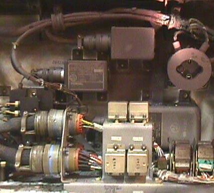
10 Wiring Installation Typical Wiring Distribution in a Fighter Wiring Must Withstand Continuous Environmental Exposure 10


11 Wiring Installation Mechanical Stresses can Lead To Insulation Cracking and Conductor Breakage Long Term Fluid Exposure Can Lead to Material Degradation 11


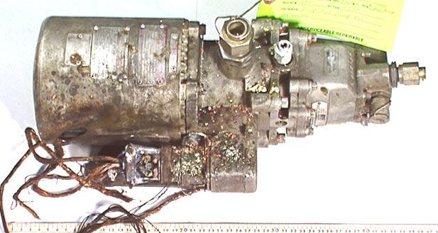
12 Excessive Temperature Aircraft Generator Cable Long Term High Temperature Exposure and Excessive Power 12


")
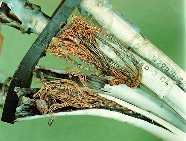
13 Arc Tracking Wire Failures Field Failure Dry Arc Tracking Polyimide Insulation (MIL-W-81381) 13
14 MIL-W Wire Used on many commercial and military aircraft 727,737,747,757,767,A-300,L-1011,MD-80, MD-11, space shuttle F-15,F16,B-1B, F-4, U-2, E-3A, B-2, C-17, Atlas, Titan III, Tomahawk, F- 18, S-3A,P-3C,AV-8B Thin wall (6 mils) and light weight Good abrasion and cut-through resistance High temperature(200 C) and high dielectric strength Flame and environmentally resistant Aromatic polyimide over wrapped to form four layers with a fluoropolymer adhesive and coated with a polyimide lacquer 14
15 Issues Concerning MIL-W Wire Insulation Arc propagation (flashover or carbon arc tracking) susceptibility- can damage adjacent wiring and materials Poor handling characteristics due to stiffness Susceptibility to degradation when exposed to water at elevated temperatures (hydrolysis) over time in combination with stress Susceptibility to degradation from high ph materials (above 12) or ultra-violet radiation (sun light) Crack propagation when notched and flexed 15
16 Arc Propagation of Mil-W Typically initiated by chafing Wet (conductive fluids) or dry conditions Conditions for failure Exposed conductor Sufficient voltage and current Physical contact required between an exposed conductor and conductive structure Collateral damage possible- causing multiple system failures Standard circuit protection devices may not respond to arc event Events are rare 85-90% of aircraft wiring at signal level voltages Several independent events must occur 16


17 In-Flight Aircraft Wiring Mishap Mil-W wiring Failure initiated by chafing Arc propagation due to circuit protection failure 17


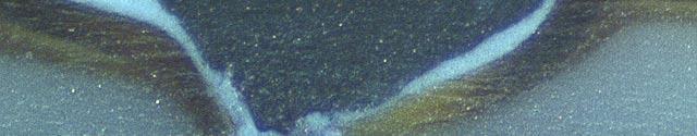
18 Arc Tracking Failures Field Wet Arc Tracking Failure Polyalkene Insulation Insulation Damage by Hot Stamp Printing Process Wiring Located in High Moisture Environment 18


19 Hot Stamped Wiring Scavenge Pump Relay Wiring Exhibited Deep Hot Stamp Marks Crack Exposed Conductor No Arcing Noted Rotated 90 degrees 0.5mm 19


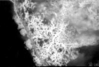
20 Hot Stamped Wire Hot Stamp Mark Areas 0.07mm Hot Stamp Mark 50 um 0.2 mm Hot Stamp Marks Cross-section of Wire Hot Stamp Area 1 mm 20


21 Wiring System Failures In-Flight Electrical Fire Initiation Site 21


22 Wiring System Failures Failure Site Hydraulic Line Ruptured by Arc Erosion Field Inspection Revealed Wire Chafing Against Hydraulic line 22
23 Aging Aircraft Wiring Systems Wiring Failure Data for a Typical Fighter 46% Broken Wires 30 % Insulation Chafing Damage 14% Outer Layer Chafing 10% Failure in Connector 23
24 AF Mishap Data for Electronic Related Failures ( ) Mishap class I P A B 0% 4% 3% 1% H 33% Aircraft Type C 59% Helicopter 5% Refueler 6% Training 12% Avionics/Recon 11% Bomber/Attack 10% Data provided by the AF Safety Agency Fighter 36% Cargo 20% 24
25 AF Mishap Data for Electronic Related Failures ( ) Age Groups of Mishap Aircraft to 5 6 to to to to to to to 53 Function System interconnections 43% electromechanical 34% total electrical failure-system unknown 1% avionics 9% flight control 11% power systems 45% fuel systems 8% electronics 23% Data provided by the AF Safety Agency instruments 26% 25
26 AF Mishap Data for Electronic Related Failures ( ) Components Contributing to AF Mishaps motors 2% resistors 1% relays 7% light fuel probe 1% switch 3% transformers 6% electric panel 8% avionics 7% batteries 1% connectors 14% capacitors 1% circuit breakers 2% 0% conductors generator 29% 18% Data provided by the AF Safety Agency 26
27 AF Mishap Data for Electronic Related Failures ( ) Function of Failed Component by Aircraft Type interconnections electronic electromechanical Bomber/Attack Cargo Fighter Data provided by the AF Safety Agency 27
28 Aircraft Electrical Failure Background Aircraft experienced partial loss of D.C. power in flight 40 Ampere circuit breakers tripped (provides the D.C. power to instruments and other avionics) Failures related to overheated 10/12 gage wire butt splice crimps Field inspection of the butt splices revealed the insulation covering the splices was overheated Manufacturers provided new butt splice and ring terminal crimps for evaluation Crimp termination resistance was measured and representative samples were pulled to failure 28


29 Splice Failures 29


30 Crimp Connections 200 SP03 SP02 SP01 SP SP C, SP C, SP C, SP04-189C 10/12 butt splice from the field J237 pin F at 45A, Tripping of the 40A D.C. breakers is due to load currents and heat generated by high resistive ring terminals and nearby butt splices A gas tight interface is not being formed in the crimp terminals 12 gage wiring provides inadequate heat sinking for the breaker A high resistance crimp connection leads to I 2 R heating that propagates heat into the 40A CB causing it to trip Inadequate crimps are the result of minimum diameter wire conductors and the type of tool used to form the 12 ga. crimp Crimp tool, even when used correctly, creates marginal or inadequate crimps on 12 ga. butt splices and ring terminals 30
31 Aircraft Electrical Failure Conclusions Electrical failure was due to the interaction of the aircraft current loads, terminations, wiring, connectors, and circuit breakers Maintenance community considered periodic replacement of terminations and circuit breakers a standard practice Engineering community was unaware of the failures Due to an ineffective data reporting process Both communities were also unaware of the changes that had occurred in the wire and crimp tool or the increased avionics loading that had occurred over several years 31
32 What can We Learn From This Incident? Electrical failures rarely result in the loss of an aircraft Robust designs and materials are used and we have well trained aircrews Electrical failures can place stress on the aircrew and impact mission effectiveness Present maintenance philosophy is reactive Aging/degradation of electrical systems not emphasized Wiring system components treated as inexpensive commodities Maintenance data collection does not give insight into wiring system failures Wiring system integrity is dependent on the interaction of linked components Power and signal distribution components make up a complex system Changes (over time) in power requirements, mission use and component design, manufacturing and materials can affect system integrity 32
33 Wiring Integrity Study of Legacy Aircraft Findings Wiring failures found after an inability to resolve a system failure or during visual inspections Wiring problem areas Fuel tank wiring Wheel wells- anti-skid systems Generator wiring Wing flaps and leading edges Pylon wiring Circuit breaker panels Control column wiring Equipment rack wiring (wiring within one foot of connectors) Wiring nexus points (wing root areas, under wings, cockpit) 33

34 Chafing and Installation Leading Edge Wing Flap Harness Moving parts in combination with grease and extreme environmental conditions cause wiring problems Double-Back harness in leading edge has problems with bolts chafing the harness 34

35 Wheel Wells SAWMP Areas Environmental exposure of connectors and wiring Wiring damaged from repeated flexing 35

36 High Maintenance Areas Circuit Breaker Panels Wiring damaged by repeated opening and closing of panels. 36


37 Latent Defects and Hidden Damage Residue visible on surface - high concentrations of silver, copper, and sulfur inch Compression damage to PTFE insulation Damage to PTFE insulation. Compression damage to PTFE insulation Exposed conductor 0.06 inch 0.06 inch 37


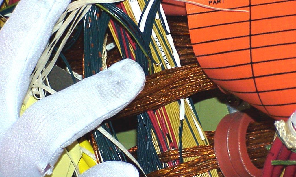
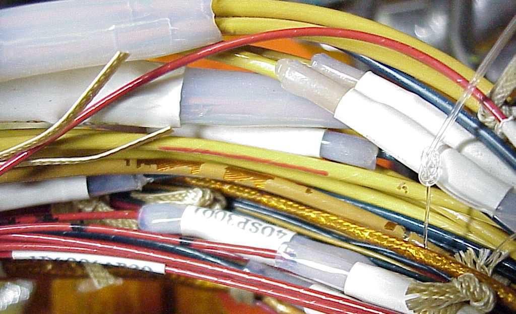
38 Repair and Installation Splices Avionics Wiring Crack in Wiring 38


39 Wire Routing 39


40 Aging Wiring 40


41 How Other Systems Can Cause Wiring Failures- Circuit Breakers Circuit Breaker Panel Close-up of Fire Damage Failure Initiated by Over Heated CB Aging of CB Contacts Caused Failure 41


42 How Other Systems Can Cause Wiring Failures- Electrical Connectors Wet Arc Tracking in Connector Breakdown of Chlorinated Elastomer Time and Environmentally Dependent Process 42


43 How Other Systems Can Cause Wiring Failures- Motors Phase C Phase A Phase B Failure Initiated by Degraded Bearings and Wire Chafing 43


44 Managing Aging Wiring Systems New Materials 1 µm Diagnostics and Inspection TECHNOLOGY INTEGRATION Managing Aging Wiring Systems Failure Characterization Interconnection Technologies Circuit Breakers Connectors Maintenance Tools 44
45 Summary of Wiring Technologies Technology Need Current Effort Future Diagnostics Detection of wiring system faults Shorts and opens Failure Characterization New Materials Interconnection technology Maintenance tools Models/Life predication Stronger, lighter and higher temperatures Mitigate arc propagation Effective application of tools Define model needs Shield conductor applications Fault sensitive CBs for transports Integration for current tools Intermittent and damaged wiring Models that can predict field performance Shield and signal conductor and insulation applications Fault sensitive CBs for fighters Complete suite of tools for managing aging wiring system 45
46 How Do We Improve Wiring Integrity? Move from a reactive to a proactive wiring system maintenance approach Technologies to make this a reality are available Infrastructure to make them successful has yet to be fully developed Use a industry and government team to: Apply new technologies and assess their effectiveness Accelerate implementation of the most promising technologies A proposed strategy is to develop research initiatives in five broad technology areas Failure characterization, diagnostics, new materials, interconnection technologies, and maintenance tools 46
47 Strategy from a Management Perspective Alter the perception of wiring systems Ensure wire systems are designed, installed, and maintained for longterm integrity using technology forums and new standards Emphasize prevention of damage to wiring systems through training, diagnostics and prognostics Transition from a reactive to a proactive maintenance approach Increase collaboration between industry, academia, and the government Develop a partnership between industry, academia, technical associations and the government- eliminate barriers Improve field data collection and promote data sharing to guide technology investment Focus resources on the identified wiring issues 47
48 Strategy from a Management Perspective Improve the management and functionality of wire systems Standardize design tools for developing and tracking design parameters and changes in the configuration of wire systems Develop detailed training for the installation, inspection, and maintenance of wire systems Promote the development and rapid deployment of diagnostics, prognostics, and new repair technologies Improve wire system technology Promote the use of advanced connection technologies- wireless, micro-electronic(mems), multiplexing, and fiber-optic systems Pursue revolutionary improvements in wire systems by developing new technologies and materials through aggressive research initiatives 48
49 Summary Wiring System Integrity Can Be Managed! Emphasis on proper design, materials selection, installation, and maintenance practices Collection and analysis of maintenance data Understanding of failure mechanisms Use of surveillance programs Treating wiring as an interconnection system Use of proactive repair and replacement programs 49
Using Vacuum Impregnation to Fill Quality Gaps for Electronics Manufacturers
 Using Vacuum Impregnation to Fill Quality Gaps for Electronics Manufacturers Scott Simmons, Business Development Manager, Henkel Chris Russell, Sales Director, Henkel ABSTRACT Often the most troublesome
DETAIL SPECIFICATION SHEET CABLE, ELECTRICAL, -20 C TO +105 C, 1000 VOLTS, TYPE LSFSGU
 INCH-POUND MIL-DTL-24643/17F 1 October 2009 SUPERSEDING MIL-DTL-24643/17E 22 August 2002 DETAIL SPECIFICATION SHEET CABLE, ELECTRICAL, -20 C TO +105 C, 1000 VOLTS, TYPE LSFSGU This specification is approved
Offshore Wind Turbines Power Electronics Design and Reliability Research
 Offshore Wind Turbines Power Electronics Design and Reliability Research F. P. McCluskey CALCE/Dept. Of Mechanical Engineering University of Maryland, College Park, MD (301) 405-0279 mcclupa@umd.edu 1
SECTION WIRE AND CABLE Raceways and Conduit Motor Power and Control Wiring.
 SECTION 16120 WIRE AND CABLE PART 1 GENERAL 1.01 SUMMARY A. Related Sections: 1. 16112 - Raceways and Conduit. 2. 16155 - Motor Power and Control Wiring. 1.02 SYSTEM DESCRIPTION A. Performance Requirements:
Friday, May 29, Update on Testing Medium Voltage Cable and Switchgear Systems
 Update on Testing Medium Voltage Cable and Switchgear Systems Friday, May 29, 2015 Presented by: Ashley Harkness Ashley.Harkness@Emerson.com Electrical Reliability Services Value--- When we find the one
Galvanic and Stray Current Corrosion
 Chapter 5 Galvanic and Stray Current Corrosion MElec-Ch5-1 Overview Galvanic Corrosion Understanding Galvanic Corrosion Controlling Galvanic Corrosion Stray Current Corrosion Understanding Stray Current
TALON Cargo Hook Troubleshooting Guide
 TROUBLESHOOTING GUIDE 125-004-00 Revision 1 As of: August 14, 2009 For all TALON Cargo Hooks TALON Cargo Hook Troubleshooting Guide TALON LC Hydraulic Hook TALON LC Cargo Hook TALON LC Keeperless Hook
Spring Pressure Connection Technology Vibration-Proof Fast Maintenance-Free
 Spring Pressure Connection Technology Vibration-Proof Fast Maintenance-Free WAGO CAGE CLAMP Technology, Can Help Reduce Costs and Increase Safety in Your Applications! Contents Reduce Costs 4 Increase
SECTION INSULATED WIRE AND CABLE
 SECTION 16120 INSULATED WIRE AND CABLE PART 1 GENERAL 1.01 DESCRIPTION A. This section covers the contract item Insulated Wire and Cable, which includes the following items with accessories, and appurtenances:
ELECTRICITY SUPPLY - POWER SYSTEM MAINTENANCE Carry out routine inspection and servicing on high voltage minimum oil circuit breakers
 1 of 9 level: 4 credit: 6 planned review date: December 2006 sub-field: purpose: entry information: Electricity Supply People credited with this unit standard are able to: prepare for inspection, testing
The University of Texas at Austin September 30, 2011
 SECTION 27 05 26 GROUNDING AND BONDING FOR COMMUNICATIONS PART 1 - GENERAL 1.1 SUMMARY A. This section governs the products and execution requirements relating to furnishing and installing grounding and
PILC Replacement: Getting the Lead Out
 PILC Replacement: Getting the Lead Out Spring Cincinnati, OH April 30, 2003 Page 1 PILC IS GREAT! Low Profile High Fault Current Capability on Shield High Degree of Water Blocking So why shouldn t you
ELECTRICAL BULLETIN
 PO Box 697 Halifax, Nova Scotia B3J 2T8 ELECTRICAL BULLETIN 2015-01 From: David MacLeod, C.E.I., P.Eng. Pg. 1 of 7 Provincial Chief Electrical Inspector Date: March 10, 2015 Subject: Adoption of the 2015
A LIGHTWEIGHT SOLUTION FOR SHIELDING AND CONDUCTING
 A LIGHTWEIGHT SOLUTION FOR SHIELDING AND CONDUCTING EMI Shielding ARACON fibers braided into a shield or sock offer superior performance against electromagnetic interference. Advantages include: More uniform
The Implications for OEMs and MROs of Wiring (EWIS) Being Regulated as an Aircraft System.
 Being Regulated as an Aircraft System.") The Implications for OEMs and MROs of Wiring (EWIS) Being Regulated as an Aircraft System. Reference: EWIS CFR14, FAR Part 25, 1701, Sub-Part H and AC25.1701-1 Abstract Advanced avionics are commonplace
The Implications for OEMs and MROs of Wiring (EWIS) Being Regulated as an Aircraft System. Reference: EWIS CFR14, FAR Part 25, 1701, Sub-Part H and AC25.1701-1 Abstract Advanced avionics are commonplace
TR1 TR2. Transformer / Relay Adapter. Installation Manual. Rev 1.1 Feb. 22, Deklin Technologies Inc 413 Childe Harolds Lane Brentwood, TN 37027
 TR1 TR2 Transformer / Relay Adapter Installation Manual Rev 1.1 Feb. 22, 2016 Deklin Technologies Inc 413 Childe Harolds Lane Brentwood, TN 37027 Tel: (615) 819-0800 Fax: (615) 819-0801 www.deklintech.com
PROBLEM PARTS, AND RELATED MATERIALS AND PROCESSES
 Date: 04/27/2004 PROBLEM PARTS, AND RELATED MATERIALS AND PROCESSES Problem Parts a. Silver case wet slug tantalum. Rationale: Cannot tolerate reverse voltage very well. Silver electroplating from the
Passive components : 5 years failure analysis feedback From all markets
 2 nd SPCD 12-14 October 2016 Passive components : 5 years failure analysis feedback From all markets Eric ZAIA (Material Engineer) Béatrice MOREAU (Passive components & PCB dpt. Manager) SUMMARY 1 Introduction
APEC 2016 Component Level Safety Certification in Systems- IEC /UL1577. MARK CANTRELL Senior Applications Engineer
 APEC 2016 Component Level Safety Certification in Systems- IEC60747-17/UL1577 MARK CANTRELL Senior Applications Engineer 3/20/2016 Agenda What is safety isolation Isolation Concepts Regulatory Landscape
Carry out routine inspection and servicing on high voltage bulk oil circuit breakers
 Page 1 of 6 Carry out routine inspection and servicing on high voltage bulk oil circuit breakers Level 4 Credits 6 Purpose People credited with this unit standard are able to: prepare for inspection, testing
DRS C3 & Aviation Integrated Manufacturing Solutions. DRS C3&A Integrated Manufacturing Solutions. All Rights Reserved.
 DRS C3 & Aviation Integrated Manufacturing Solutions IMS Executive Overview 1 IMS Core Capabilities Productization Program Management Supply Chain Services Kitting Services Molding Fiber Optics Circuit
MECHANICAL AND PHYSICAL PROPRIETIES
 Kera-Coat Ceramic Coatings are Special Ceramic Coating defined as a substantially vitreous or glassy inorganic coating bonded to metal by fusion at a temperature above 800 F. In this short abstract we
3M Cold Shrink Silicone Rubber Connector Insulators 8440 Series
 3M Cold Shrink Silicone Rubber Connector Insulators 8440 Series Data Sheet May 2014 Product Description 3M Cold Shrink Connector Insulators 8440 Series are open-ended, silicone rubber, tubular sleeves.
Instructions for Continued Airworthiness Talon LC Keeperless Cargo Hook Kit For the AS350 Series. System Part Number STC SR00886SE
 Instructions for Continued Airworthiness Talon LC Keeperless Cargo Hook Kit For the AS350 Series System Part Number 200-261-00 STC SR00886SE 13915 NW 3 rd Court Vancouver Washington 98685 USA Phone: 360-546-3072
PERFORMANCE SPECIFICATION SHEET
 INCH-POUND MIL-PRF-29504/18 25 November 2008 PERFORMANCE SPECIFICATION SHEET TERMINI, FIBER OPTIC, CONNECTOR, REMOVABLE, ENVIRONMENT RESISTING, GENDERLESS TERMINUS, REAR RELEASE, CERAMIC FERRULE, 1.25
Title: YALE OFFICE OF FACILITIES PROCEDURE MANUAL Chapter: 01 - Yale Design Standard Division: Electrical Standards
 Change History Date Description of Change Pages / Sections Modified Change Approver Initials 6/15/16 Updated division section from 16124 to 2605 - mgl44 13, removed references to other section 10/17/14
ROLINX Laminated Busbar. Design Rules Version 01 (12/2015)
") ROLINX Laminated Busbar Design Rules Version 01 (12/2015) Content 1. Introduction... 03 7. Features... 13 2. Configuration...03 8. Thermal parameters... 14 3. Products... 04 9. General parameters... 14
ROLINX Laminated Busbar Design Rules Version 01 (12/2015) Content 1. Introduction... 03 7. Features... 13 2. Configuration...03 8. Thermal parameters... 14 3. Products... 04 9. General parameters... 14
Discrete Capacitor & Resistor Issues. Anthony Primavera Boston Scientific CRM 11/13/06
 Discrete Capacitor & Resistor Issues Anthony Primavera Boston Scientific CRM 11/13/06 Goal: Drive the Industry towards common test methods and best practices in manufacturing to reduce and or eliminate
Detailed Requirements Document (DRD) Rail Engineering Advanced Technician Level 4 Electrification Knowledge & Skills Content
 Rail Engineering Advanced Technician Level 4 Electrification Knowledge & Skills Content") Detailed Requirements Document (DRD) Rail Engineering Advanced Technician Level 4 Electrification Knowledge & Skills Content Purpose The purpose of this Detailed Requirements Document (DRD) is to provide
Detailed Requirements Document (DRD) Rail Engineering Advanced Technician Level 4 Electrification Knowledge & Skills Content Purpose The purpose of this Detailed Requirements Document (DRD) is to provide
Introduction. Origin
 Company Profile Introduction Together, Management have 50years of Siemens Product Experience to ensure that our customers receive the correct product the first time. We have a Level 2 (two) B-BBEE procurement
The Canadian Electrical Code (Saskatchewan Amendments) Regulations, 1999
 Regulations, 1999") CANADIAN ELECTRICAL CODE 1 The Canadian Electrical Code (Saskatchewan Amendments) Regulations, 1999 Repealed by Chapter E-6.3 Reg 8 (effective June 24, 2003). Formerly Chapter E-6.3 Reg 6 (effective March
CANADIAN ELECTRICAL CODE 1 The Canadian Electrical Code (Saskatchewan Amendments) Regulations, 1999 Repealed by Chapter E-6.3 Reg 8 (effective June 24, 2003). Formerly Chapter E-6.3 Reg 6 (effective March
GORE SKYFLEX aerospace materials
 GORE SKYFLEX aerospace materials Tapes and Gaskets Proven materials for sealing and surface protection challenges GORE SKYFLEX Aerospace Materials are a portfolio of unique, commercially-available material
Shur-Shot X-Proof Hydrogen Fluoride Alarm Operations Manual
 Shur-Shot X-Proof Hydrogen Fluoride Alarm Operations Manual P/N 1000006053 Rev E $7%$QDO\WLFV// //& 733 Dairy Rd. Parkton, Md. 21120 www.atbanalytics.com (410) 733-6365 Table of Contents Chapter 1: Getting
Adequate Protection Systems for Reduction of Wear on Tornado Aircraft
 Adequate Protection Systems for Reduction of Wear on Tornado Aircraft Lt. Franco Bagnoli Chemistry Department Flight Test Center M. De Bernardi Airport via Pratica di Mare 45 00040 Pratica di Mare Pomezia
FAA APPROVED ROTORCRAFT FLIGHT MANUAL SUPPLEMENT
 FAA APPROVED ROTORCRAFT FLIGHT MANUAL SUPPLEMENT STC SR00713SE for the Bell 204B, 205A, 205A-1, 205B, 210, 212, 412, 412EP, 412CF Agusta AB412, AB412EP Rotorcraft Dev. Corp. UH-1H, Northwest Rotorcraft
Tantalum Wet Electrolytic Capacitor
 INTRODUCTION The structure of a Tantalum Wet Electrolytic Capacitor consists of four main elements: a primary electrode (anode), dielectric, a secondary electrode system (cathode) and a wet (liquid) electrolyte.
IEEE 1580 Type P MOR Polyrad XT-125 Multi Conductor
 TABLE OF CONTENTS SECTION SUBJECT PAGE I. SCOPE...1 II. APPLICABLE DOCUMENTS...1 III. CONDUCTOR...2 IV. SEPARATOR...2 V. INSULATION...2 A. Physical Properties...2 B. Electrical Properties...3 C. Qualification
Penn State Forestland Management Office Multi-Strand High-Tensile Wire Fence Specifications
 Penn State Forestland Management Office Multi-Strand High-Tensile Wire Fence Specifications 1. FENCE REQUIREMENTS Hazard Trees All hazard trees, which are within tree length of the fence, must be felled
Heritage Quality Performance
 FEP FEATURES AND PROPERTIES Heritage Quality Performance Extruded, FEP insulated, high voltage wire and cable offers exceptional dielectric strength without the disadvantages common to equally rated silicone
Transmission Owner Asset Management
 Transmission Owner Asset Management Pieces of Asset Management New customers, load growth, repairs, maintenance, operational issues, etc. All the pieces make up the asset management plan for repair or
SECTION MANUFACTURED ROOF EXPANSION JOINTS
 SECTION 07 71 29 - MANUFACTURED ROOF EXPANSION JOINTS PART 1 -GENERAL 1.1 RELATED DOCUMENTS A. Drawings and general provisions of the Contract, including General and Supplementary Conditions and Division
UPS Electrical Design and. Installation. critica POWER SUPPLIES
 UPS Electrical Design and critica POWER SUPPLIES Installation Important considerations for the electrical design and installation of UPS systems in mission critical applications Where Critical Power applications
A New Structural Bonding Process for Ferromagnetic Sheet Stacking used in Electric Motors (Rotors, Stators )
") A New Structural Bonding Process for Ferromagnetic Sheet Stacking used in Electric Motors (Rotors, Stators ) Christophe Casteras *, Bruno Bonduelle** and Frederic Martin*** Abstract A new structural bonding
A New Structural Bonding Process for Ferromagnetic Sheet Stacking used in Electric Motors (Rotors, Stators ) Christophe Casteras *, Bruno Bonduelle** and Frederic Martin*** Abstract A new structural bonding
UFGS (August 2010) UNIFIED FACILITIES GUIDE SPECIFICATIONS
 UNIFIED FACILITIES GUIDE SPECIFICATIONS") USACE / NAVFAC / AFCEC / NASA UFGS-26 35 33.00 40 (August 2013) --------------------------------- Preparing Activity: NASA Superseding UFGS-26 35 33.00 40 (August 2010) UNIFIED FACILITIES GUIDE SPECIFICATIONS
USACE / NAVFAC / AFCEC / NASA UFGS-26 35 33.00 40 (August 2013) --------------------------------- Preparing Activity: NASA Superseding UFGS-26 35 33.00 40 (August 2010) UNIFIED FACILITIES GUIDE SPECIFICATIONS
Component Palladium Lead Finish - Specification Approved by Executive Board 1997-xx-xx August 22 Version
 Component Palladium Lead Finish - Specification Approved by Executive Board 1997-xx-xx August 22 Version Appendices 1. User Commitment Form 2. Supplier Compliance Form Table of contents 1. Background 2.
SERVICE BULLETIN Document No Rev 0 Date: February 9, 2007
 13915 NW 3 rd Court Vancouver, WA 98685 Phone: 360-546-3072 Fax: 360-546-3073 SERVICE BULLETIN Document No. 159-017-00 Rev 0 Date: February 9, 2007 Subject: Cargo Hook Stress Corrosion Cracks. Helicopters
Thermal-Tab and Thermal-Ribbon Sensors
 Thermal-Tab and Thermal-Ribbon Sensors Install these compact sensors anywhere for accurate point sensing and fast response. All Thermal-Tab modules use a thin-film RTD element. All Thermal-Ribbon models
Telecommunication Spaces
 Telecommunication Spaces October 19, 2016 Page 1 Revision History Telecommunication Spaces Standard Effective Date Email Version Contact Phone OIT-TS strevena@csustan.edu 1.0 Stan Trevena 209.667.3137
Long Beach July 2015 Secondary Network Outages RCE. Summary and Report
 Long Beach July 2015 Secondary Network Outages RCE Summary and Report 1 P age Table of Contents Background... 3 Root Cause... 5 Chronology... 7 Immediate, Interim, and Corrective Actions... 12 Exhibit
FAA APPROVED ROTORCRAFT FLIGHT MANUAL SUPPLEMENT STC SR01164SE
 FAA APPROVED ROTORCRAFT FLIGHT MANUAL SUPPLEMENT STC SR01164SE Swing Suspension System With Talon LC Hydraulic Cargo Hook Airbus Helicopter Models AS350B, AS350B1, AS350B2, AS350B3 AS350BA & AS350D R/N
Space Environmental Hazards For Space and Launch Systems
 Space Environmental Hazards For Space and Launch Systems Dr. Joseph E. Mazur The Aerospace Corporation Presentation to the 2012 FAA Commercial Space Transportation Conference Physical Sciences Laboratory
SSC06-IX-7. Lessons Learned Developing Separation Systems For Small Satellites
 Lessons Learned Developing Separation Systems For Small Satellites Walter Holemans, 20 th Annual AAIA/USU, August 2006 Planetary Systems Corporation, 2303 Kansas Avenue, Silver Spring MD 20910, (301) 495-0737,
PRELIMINARY. HTHA (Z1-Foil)
") Ultra High Precision Z1-Foil Technology Chip Resistor for Hybrid Circuits with Aluminum Wire Bonding for High Temperature Applications up to +240 C, Long Term Stability of 0.05%, TCR to ± 1ppm/ C INTRODUCTION
Ultra High Precision Z1-Foil Technology Chip Resistor for Hybrid Circuits with Aluminum Wire Bonding for High Temperature Applications up to +240 C, Long Term Stability of 0.05%, TCR to ± 1ppm/ C INTRODUCTION
HTHA (Z1-Foil) Vishay Foil Resistors
 Vishay Foil Resistors") Ultra High Precision Z1-Foil Technology Chip Resistor for Hybrid Circuits with Aluminum Wire Bonding for High Temperature Applications up to +240 C, Long Term Stability of 0.05%, TCR to ± 1ppm/ C INTRODUCTION
Ultra High Precision Z1-Foil Technology Chip Resistor for Hybrid Circuits with Aluminum Wire Bonding for High Temperature Applications up to +240 C, Long Term Stability of 0.05%, TCR to ± 1ppm/ C INTRODUCTION
WE11S GMA (MIG) Fillet Weld
 Fillet Weld") Uniform Procedures For Collision Repair WE11S GMA (MIG) Fillet Weld 1. Description This procedure describes methods for making and inspecting GMA (MIG) fillet welds on automotive steel. 2. Purpose The
Uniform Procedures For Collision Repair WE11S GMA (MIG) Fillet Weld 1. Description This procedure describes methods for making and inspecting GMA (MIG) fillet welds on automotive steel. 2. Purpose The
B. Provide liquid-filled secondary substation transformers as indicated on drawings.
 SECTION 26 12 13 PART 1 - GENERAL 1.01 WORK INCLUDED A. Comply with the provisions of Sections 26 05 00. B. Provide liquid-filled secondary substation transformers as indicated on drawings. 1.02 RELATED
Table of Contents. Applications...3. Extruded Sizes...7. Value Added Services Heat Shrinkable Extrusions Technical Information...
 Table of Contents Applications...3 Medical...4 Industrial...5 Extruded Sizes...7 PTFE Sub-Lite-Wall Extruded&HeatShrinkableTubing...8 ExtrudedTubing(AWG)...10 HeavyConstructionTubing...14 HeavyWallTubing...15
WE01A GMA (MIG) Plug Weld
 Plug Weld") Uniform Procedures For Collision Repair WE01A GMA (MIG) Plug Weld 1. Description This procedure describes methods for making and evaluating gas metal arc (GMA) plug welds (MIG plug welds) on all types
Uniform Procedures For Collision Repair WE01A GMA (MIG) Plug Weld 1. Description This procedure describes methods for making and evaluating gas metal arc (GMA) plug welds (MIG plug welds) on all types
Qualification Reference: AA/ Cage Code: MIL-C Cables NEMA WC27500 Part Number Builder
 Qualification Reference: 15404201.AA/1-20-2015 Cage Code: 67050 MIL-C-27500 Cables NEMA WC27500 Part Number Builder MIL-C-27500 Cables NEMA WC 27500 Part Number Builder MIL-C-27500 (M27500 Cable) MIL Spec
3M Electrical, Electronic and EMI Shielding Tapes Selection Guide
 3M Electrical, Electronic and EMI Shielding Tapes Selection Guide 3M Electrical Tapes Operating Temperature ( C) Dielectric Breakdown (Volts) Insulation Resistance (megohms) (lb/in)/(n/10 mm) Elongation
(EMPENNAGE) 1. Fresh Air Inlet -- CLEAR 2. Tail Tie Down -- DISCONNECT 3. Control Surfaces -- CHECK
 1. Fresh Air Inlet -- CLEAR 2. Tail Tie Down -- DISCONNECT 3. Control Surfaces -- CHECK") NORMAL PROCEDURES 8. Leading Edge -- CHECK 9. Aileron & Flap -- CHECK PREFLIGHT (EMPENNAGE) 1. Fresh Air Inlet -- CLEAR 2. Tail Tie Down -- DISCONNECT 3. Control Surfaces -- CHECK CABIN: 1. POH & Documents
NORMAL PROCEDURES 8. Leading Edge -- CHECK 9. Aileron & Flap -- CHECK PREFLIGHT (EMPENNAGE) 1. Fresh Air Inlet -- CLEAR 2. Tail Tie Down -- DISCONNECT 3. Control Surfaces -- CHECK CABIN: 1. POH & Documents
CONTACT ELECTRICAL CHARACTERISTICS TIGER CLAW CONTACT TESTING. A. Gas Tight
 CONTACT ELECTRICAL CHARACTERISTICS TIGER CLAW CONTACT TESTING A. Gas Tight 1. Purpose - To evaluate the integrity of the contact interface by assessment of the gas tight characteristics of the contacting
Installation, Inspection and Maintenance of Dry Type Transformers
 Dry Type TX 1 of 8 Installation, Inspection and Maintenance of Dry Type Page 1 of 8 Dry Type TX 2 of 8 Table Of Contents Page Number 1. General... 3 2. Installation... 3 3. Safety Inspections... 4 4. Safety
Specialty Multimode Graded-Index Fiber
 Specialty Fiber MM Graded-Index Fibers Fiber Name 50/125 62.5 50/125 Hermetic 50/125 Acrylate 100/140 Acrylate 100/140 High-Temp 100/140 Dual Acrylate 100/140 Unbuffered 100/140 Buffered Geo50 Core/Clad/Buffer
INSTALLATION MANUAL AND OPERATING INSTRUCTIONS
 INSTALLATION MANUAL AND OPERATING INSTRUCTIONS MD41-( ) Series GPS ANNUNCIATION CONTROL UNIT FOR NORTHSTAR M3 GPS APPROACH MD41-828 28vdc Horizontal Mount MD41-838 28vdc Vertical Mount (shown on page 13)
PLEASE READ INSTRUCTIONS IN CONJUNCTION WITH THE ILLUSTRATIONS. PLEASE SAVE THESE INSTRUCTIONS
 VAUFHM Underfloor Heating Mat Range Installation and Wiring Instructions Stock Ref. N 446175 446192 446176 446193 446177 446194 446178 446195 446179 446196 446180 446197 446181 446198 446182 446199 446183
Coatings. Ion Assisted Deposition (IAD) process Advance Plasma Source (APS) plasma-ion assisted Deposition. Coatings on Optical Fibers
 process Advance Plasma Source (APS) plasma-ion assisted Deposition. Coatings on Optical Fibers") Anti-Reflection Custom Ion Assisted Deposition (IAD) process Advance Plasma Source (APS) plasma-ion assisted Deposition Anti-Reflection on Optical Fibers OptoSigma supplies a wide selection of optical
Anti-Reflection Custom Ion Assisted Deposition (IAD) process Advance Plasma Source (APS) plasma-ion assisted Deposition Anti-Reflection on Optical Fibers OptoSigma supplies a wide selection of optical
Title: YALE OFFICE OF FACILITIES PROCEDURE MANUAL Chapter: 01 - Yale Design Standard Division: Electrical Standards
 Date Description of Change Pages / Sections Modified ID 6/15/16 Updated format, division title, and removed references to other sections. - mgl44 A. Summary This section contains design criteria for the
ELECTRICAL SAFE WORK PRACTICES
 ELECTRICAL SAFE WORK PRACTICES I. PURPOSE To establish minimum acceptable standards for AC and DC electrical safe work practices. The program includes requirements for the training of qualified and unqualified
CONSOLIDATED EDISON COMPANY OF NEW YORK, INC Van Dam Street Long Island City, NY ELECTRIC METER SHOP DEPARTMENT
 CONSOLIDATED EDISON COMPANY OF NEW YORK, INC. 48-05 Van Dam Street Long Island City, NY 11101 ELECTRIC METER SHOP DEPARTMENT METER ENGINEERING SPECIFICATION MES-350 REVISION 3 June 2016 EFFECTIVE DATE
ELECTRICAL BULLETIN
 PO Box 697 Halifax, Nova Scotia B3J 2T8 Labour and Advanced Education ELECTRICAL BULLETIN 2012-01 From: David MacLeod,C.E.I.,P.Eng. Pg 1 of 8 Provincial Chief Electrical Inspector Date : March 1, 2012
Power Quality tools. Recorders. Troubleshooters. Loggers. for industrial and commercial applications.
 Power Quality tools for industrial and commercial applications. Recorders Loggers Troubleshooters Power quality overview What is power quality? How reliably can your systems operate their loads? That is
CONDUITS AND FITTINGS
 CONDUIT AND FITTINGS Rigid Steel Conduit 3801 Rigid PVC Conduit 3803 HDPE Conduit 3803 Flexible Non Metallic Liquid Tight Conduit Type LFNC-B 3804 PVC Coated Urethane Lined Galvanized Rigid Steel Conduit
Assembling, wiring and testing electrical panels/components mounted in enclosures
 Unit 035 Assembling, wiring and testing electrical Level: 2 Credit value: 14 NDAQ number: 500/9514/6 Unit aim This unit covers the skills and knowledge needed to prove the competences required to assemble,
U.V resistance UL Sunlight Resistance. Flame retardant IEC
 Cable for underground power distribution and subtransmission. Description Application Underground power distribution and subtransmission. As transformer feeders in substations. In power plants, industrial
Table of Contents. Applications...3 Medical...4 Industrial...5
 Table of Contents Applications...3 Medical...4 Industrial...5 Extruded Sizes...7 PTFE Sub-Lite-Wall Extruded&HeatShrinkableTubing...8 ExtrudedTubing(AWG)...10 HeavyConstructionTubing...14 HeavyWallTubing...15
7Terminals and Splices
 Introduction Product Facts No need f inhibit agents, thanks to our dry crimp technique Terminating/splicing capabilities f stranded aluminum wire, plus splicing of aluminum wire to copper wire conducts
E³.series Electrical Wiring, Control Systems and Fluid Engineering Software
 P R O D U C T O V E R V I E W Z u k e n T h e P a r t n e r f o r S u c c e s s E³.series Electrical Wiring, Control Systems and Fluid Engineering Software z u k e n. c o m / E 3 s e r i e s Z u k e n
LOW TEMPERATURE PHOTONIC SINTERING FOR PRINTED ELECTRONICS. Dr. Saad Ahmed XENON Corporation November 19, 2015
 LOW TEMPERATURE PHOTONIC SINTERING FOR PRINTED ELECTRONICS Dr. Saad Ahmed XENON Corporation November 19, 2015 Topics Introduction to Pulsed Light Photonic sintering for Printed Electronics R&D Tools for
DIVISION 26 ELECTRICAL Electrical Power Conductors and Cables
 PART 1 - GENERAL 1.01 DESIGN REQUIREMENTS A. Scope: Power Conductors and Cables in this section are defined as system voltages above 120V and less than 600V. B. System Voltages Three Phase and Single Phase:
DMRC ELECTRICAL STANDARDS & DESIGN WING (DESDW)
") DELHI METRO RAIL CORPORATION LIMITED DMRC ELECTRICAL STANDARDS & DESIGN WING (DESDW) SPECIFICATION NO. DMES- T/0018/ DMRC-E-TR-CABLE-2 SPECIFICATIONS FOR 33 kv CABLES FOR ELEVATED AND Issued on: Date Stage
DELHI METRO RAIL CORPORATION LIMITED DMRC ELECTRICAL STANDARDS & DESIGN WING (DESDW) SPECIFICATION NO. DMES- T/0018/ DMRC-E-TR-CABLE-2 SPECIFICATIONS FOR 33 kv CABLES FOR ELEVATED AND Issued on: Date Stage
Axle Surface Coatings IMechE Seminar 2014
 Excellence In All We Do Axle Surface Coatings IMechE Seminar 2014 Page 1 Axle Surface Coatings Alternatives to current UK practices UK axle surface coatings Limitations of UK axle surface coatings Alternative
SECTION HVAC INSULATION
 PART 1 GENERAL 1.1 SUMMARY SECTION 23 07 00 HVAC INSULATION A. Section Includes: 1. Ductwork insulation. 2. Duct liner. 3. Insulation jackets. 4. Equipment insulation 5. Piping system insulation. 6. Insulation
FIVE STAR PRODUCTS, INC. (800)
") FIVE STAR PRODUCTS, INC. www.fivestarproducts.com (800) 243-2206 Page 1 of 11 DESIGN-A-SPEC GUIDELINES FIVE STAR RS ANCHOR GEL CONTENTS PART A - GENERAL CONDITIONS PART B - MATERIAL SPECIFICATIONS PART
FIVE STAR PRODUCTS, INC. www.fivestarproducts.com (800) 243-2206 Page 1 of 11 DESIGN-A-SPEC GUIDELINES FIVE STAR RS ANCHOR GEL CONTENTS PART A - GENERAL CONDITIONS PART B - MATERIAL SPECIFICATIONS PART
Lightning exposure of Carbon Fiber Composites in wind turbine blades
 105 24 th Nordic Insulation Symposium on Materials, Components and Diagnostics Lightning exposure of Carbon Fiber Composites in wind turbine blades Søren Find Madsen, Lisa Carloni Global-Lightning Protection
WELDING Topic and Contents Hours Marks
 Topic and Contents Hours Marks 3.1 Introduction 04 Marks Classification and selection of welding process. Working principle of Gas welding and types of flames. 3.2 Arc welding process 08 Marks Metal arc,
INSTALLATION MANUAL AND OPERATING INSTRUCTIONS
 INSTALLATION MANUAL AND OPERATING INSTRUCTIONS MD41-( ) Series GPS ANNUNCIATION CONTROL UNIT FOR II MORROW APOLLO 2001TSO / 2001GPS / 2101/ GX50 / GX60 MD41-728 28vdc Horizontal Mount MD41-738 28vdc Vertical
A Study of Environmental Test Sequences for Electrical Units Jung Ho Yang, Yong Soo Kim
 A Study of Environmental Test Sequences for Electrical Units Jung Ho Yang, Yong Soo Kim Abstract Electrical units are operated by electrical and electronic components. An environmental test sequence is
Section ARMORED MEDIUM VOLTAGE CABLES SHIELDED 3 CONDUCTOR POWER CABLE - INTERLOCKED ARMOR
 PART 1 - GENERAL Section 26 05 15 SHIELDED 3 CONDUCTOR POWER CABLE - INTERLOCKED ARMOR 1.1 Cable shall be 15 kv, shielded, three conductor with ground, stranded copper, with continuously welded and corrugated
Quality and Reliability Report
 Quality and Reliability Report Product Qualification MASW-007921 2mm 8-Lead Plastic Package QTR-0148 M/A-COM Technology Solutions Inc. 100 Chelmsford Street Lowell, MA 01851 Tel: (978) 656-2500 Fax: (978)
FAIRBANKS NIJHUIS SUBMERSIBLE SOLIDS HANDLING PUMPS.
 FAIRBANKS NIJHUIS SUBMERSIBLE SOLIDS HANDLING PUMPS www.fairbanksnijhuis.com FAIRBANKS NIJHUIS Introduction Fairbanks Nijhuis manufactures a complete line of submersible pumps for municipal and industrial
INSTALLATION MANUAL AND OPERATING INSTRUCTIONS
 INSTALLATION MANUAL AND OPERATING INSTRUCTIONS MD41-( ) Series GPS ANNUNCIATION CONTROL UNIT FOR ALLIED SIGNAL KLN 900 MD41-1924 14vdc Horizontal Mount MD41-1934 14vdc Vertical Mount (shown on page 11)
Heatshrink & Cable Repair Solutions
 PAGE EASI-SHRINK HEATSHRINK SLEEVING ZERO-HALOGEN HEATSHRINK SLEEVING DR-25 HEATSHRINK TUBING KYNAR HIGH TEMPERATURE HEATSHRINK HEATSHRINK KITS ADHESIVE LINED HEATSHRINK SLEEVING 347-348 349-350 351 352
NORTHWESTERN UNIVERSITY PROJECT NAME JOB # ISSUED: 03/29/2017
 SECTION 26 0526 - GROUNDING AND BONDING FOR ELECTRICAL SYSTEMS PART 1 - GENERAL 1.1 RELATED DOCUMENTS A. Drawings and general provisions of the Contract, including General and Supplementary Conditions
BASIC CONCEPTS IN ELECTRICAL DESIGN. Prepared by Engr. John Paul Timola
 BASIC CONCEPTS IN ELECTRICAL DESIGN Prepared by Engr. John Paul Timola ELECTRICAL CONDUCTORS AND INSULATORS Electrical Conductors substances that offer a very low resistance to current flow. Insulators
A. All materials shall be listed by an OSHA approved Nationally Recognized Testing Laboratory (NRTL).
.") 16120 WIRE AND CABLE ************************************************************************************************************* SPECIFIER: CSI MasterFormat 2004 number: 26 05 19 An optional keynote
16120 WIRE AND CABLE ************************************************************************************************************* SPECIFIER: CSI MasterFormat 2004 number: 26 05 19 An optional keynote
3M Electromagnetic Compatible Products
 3M Electromagnetic Compatible Products Selection Guide Revision E 3 Innovation Faster, smaller, lighter, easier the skyrocketing development of today s electronics requires new solutions for significant
Manufacturer service provision
 Manufacturer service provision For increased equipment durability COUV 187 A Maintenance packages The expertise of a single design, manufacture and maintenance supplier Since 1968, SOCOMEC has been developing
Hazards. Hazards. Hazards. Effects on the Body. GA Tech Electrical Safety Presentation
 Hazards The direct result can be electrocution. SHOCK. Electric shock occurs when the human body becomes part of the path through which current flows. The indirect result can be injury resulting from a
Table of Contents. A Operate and monitor Micro Hydel Power Plant (MHP) plant 04
 plant 04") Page 2 Table of Contents Competency Standards A Operate and monitor Micro Hydel Power Plant (MHP) plant 04 B Carry out corrective maintenance procedures on electrical components in a MHP plant 05 C Carry
Page 2 Table of Contents Competency Standards A Operate and monitor Micro Hydel Power Plant (MHP) plant 04 B Carry out corrective maintenance procedures on electrical components in a MHP plant 05 C Carry