FINAL DETAILED DESIGN AND DRAWING REPORT RESTORATION OF BASIC STRIP & PREVENTION OF SOIL EROSION AT SHIMLA AIRPORT PART I, STAGE - II
|
|
|
- Elfrieda Neal
- 6 years ago
- Views:
Transcription


1 FINAL DETAILED DESIGN AND DRAWING REPORT RESTORATION OF BASIC STRIP & PREVENTION OF SOIL EROSION AT SHIMLA AIRPORT PART I, STAGE - II JANUARY 2016 CONSULTANTS AIRPORTS DIVISION PLOT NO. 144, SECTOR 44, GURGAON, (HARYANA) Ph / 302,, Fax: airports@rites.com, web site:
2
3
4 CONTENTS 1.0 Preamble Scope of Detailed Design & Drawings - Stage II Geotechnical Parameters Topography and Slope stabilization around the Runway Structural Configuration Reinforced Soil Structure on LHS Reinforced Soil Structure on RHS Gabion Toe wall Design of Structures - Composite Soil Reinforcement System Basis for Design Sections Selected For Analysis Load Combinations and Load Factors Partial Material Factors and Safety Factors Design Parameters Design Summary Design of Structures Gabion Wall Erosion Protection Drainage Scheme Surface Capping Scheme Instrumentation and Monitoring Objective of Instrumentation Nature of instrumentation planned Benefits of Instrumentation Monitoring of the Structure Summary and Recommendations References Annexure Annex I : Geotechnical Investigation Report Annex II : Calculation of Traffic load Annex III : Calculation for seismic coefficient Annex IV : Analysis reports for composite soil reinforcement system Annex V : Calculation for Drainage Scheme Annex VI : Calculation of Drainage Composite Shimla Airport Detailed Design Drawings Report 2 Part I stage II.
5 1.0 Preamble Shimla Airport is located on mountain close to Jubbarhatti Village, and is a table top airport. The airport has been classified as ICAO reference code 2B suitable for operation of DO-228 type of aircraft in fair weather condition. Operations are presently unidirectional in fair weather condition. Airport Authority of India (AAI) has appointed RITES Ltd. (RITES) as a consultant for providing engineering services to restore the runway strip of 1370 x 80m (this includes 1190 m runway + 60 m over run portion at either end of runway + 30m RESA on each end) and prevention of soil erosion as Part I of project and conducting feasibility studies for extension of the existing runway to the extent possible as Part II of the project. The Part I of the project has been divided in five stages. RITES have awarded sub-consultancy for the project to Genstru Consultants Pvt. Ltd. (GENSTRU) on 11 th Dec., A part of Stage I of the project, preliminary report was submitted to AAI. The preliminary report briefed about Project requirements, topography, geology, issues that were identified based on visual inspection during the site visits were briefed in the preliminary report. Solutions were proposed for issues identified to restore the runway strip were included in the report and budgetary cost estimate for the restoration works was also presented in the preliminary report. The runway strip width of 100 m was considered including provision of 3.75m wide inspection road all along the periphery of the runway strip. A concurrence to proceed with the detailed design and drawings i.e., Stage II for the project was received on 25 th September, A detailed design report for Stage II in Jan 2014 to AAI. The report mainly included detailed design and drawings for slope stabilization measures, erosion protection measures, drainage system to be provided around the runway. IIT Delhi was entrusted to proof check the design and drawings submitted under Stage Shimla Airport Detailed Design Drawings Report 3 Part I stage II.
6 II of the project by AAI. Several meetings and discussions were held with Dr. J. T. Shahu (Professor) and Dr. D. Manna (Associate Professor) of Department of Civil Engineering, IIT Delhi for approval of design and drawings. The design and drawings and cost estimate was prepared considering runway strip of 100m width i.e., 50m on either side of centerline of runway. Giving due considerations to the detailed cost estimates, it was decided by AAI to limit the runway strip width to 80m i.e., 40 m on either side of centerline of runway. This change in requirement of runway strip width was conveyed by AAI vide letter no. AAI/CHQ/Engg (C )/ Shimla/ Consultancy/ 210 dated With the change in requirement of runway strip width from 50m to 40m on either side of centerline, all the design and drawings were required to be modified. There is substantial reduction in requirement of reinforced soil structure on either side of the runway. This report presents detailed design and drawings for slope stabilization measures required on either side of the runway strip considering the width of strip as 40m on either side of runway centreline, erosion protection measures, the drainage schemes to be provided around the runway including cross drains and the surface capping system. Recommendations of IIT Delhi on various aspects of design have been incorporated in the revised design submitted as a part of this report. This report has also incorporated compliances to observations/ comments by IIT Delhi vide letter dated 20 th November 2015, 1 st December 2015 and 7 th December Scope of Detailed Design & Drawings - Stage II Based on preliminary investigations carried out during Stage I, issues such as slope instability, erosion, revamping the existing drainage arrangement were identified for restoration of runway strip of 1370m. In this stage, i.e., Stage II, detailed design and drawings have been prepared for: a. Slope stabilization on either side of runway b. Drainage, c. Erosion protection Shimla Airport Detailed Design Drawings Report 4 Part I stage II.
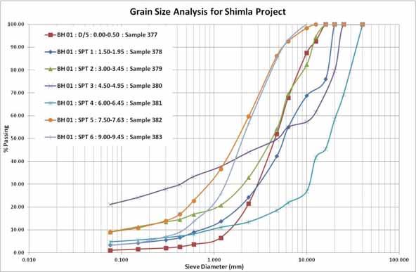
7 d. Prevention of infiltration into the runway strip. 3.0 Geotechnical Parameters Geotechnical investigation was carried out at project site by taking 4 boreholes, six trial pits, and reconnaissance survey to identify geological features of the area. Geotechnical investigation report has been enclosed as Annexure I. As can be seen from the geotechnical investigation report, the sub surface, in general, comprises of two distinct strata: Strata 1 Sandy gravel to silty sand Strata 2 Highly weathered rock The shear strength parameters for strata 1 i.e., Sandy gravel to silty sand has been derived from the SPT values. The average SPT N values for sandy gravel to silty sand is 27. The angle of internal friction as per IS:6403 for SPT N value of 27 is 35. The rock properties are derived from the software RocLab, giving due consideration to the findings of investigation. The RocLab analysis is presented in Annexure I. The shear strength parameters for the soil and rock strata are given in Table 1 below. Table 1. Shear Strength parameters for strata 1 and 2 Strata Unit Weight ϒ b (kn/m 3 ) Cohesion (kn/m 2 ) Ø (Degrees) Sandy gravel to silty sand Highly weathered rock Topography and Slope stabilization around the Runway The Shimla airport has runway strip with NW-SE orientation. The airport was constructed by cutting down the mountaintop and leveling the area to form a table top. The runway is situated at an elevation of m above mean sea level (AMSL). The excavated material has been dumped on either side of the runway. Shimla Airport Detailed Design Drawings Report 5 Part I stage II.
8 Topography and slope stabilization on Left hand side (LHS) of the Runway For chainage 0 to 570 m on LHS, required land is available at the tabletop for providing a 40m wide runway strip beyond the centerline. The slope beyond the table land upto chainage 570m in general varies between 26 o to 30 with respect to horizontal in most of the areas. However, surface erosion and gully formation has been observed in some parts of this stretch. Beyond chainage 570m upto chainage 960m the slope on LHS side just beyond the table land is relatively steep i.e., 36 o to 63 o with respect to horizontal. Secondly in stretch between chainage 740 to 830, the table top land width beyond runway centerline on LHS side is just about 40m. Beyond chainage 990 the table land widens. Width of more than 40 m is available from centerline of runway upto chainage 1260m. However, slope beyond the table top is steep in this area. Beyond chainage 1260m the width of the table land narrows down and reduces to about 24m from centerline. Over a period of time since the construction of the airport, there has been steady erosion of the slopes rendering the slopes unstable at quiet few locations. Tension cracks have been observed on the crest of the slope close to the edge of the tableland between chainage 1080 to 1170m on left hand side (LHS) of runway. Topography and slope stabilization on Right hand side (RHS) of Runway For chainage 0 to 1170m on RHS, required land is available at the tabletop for providing a 40m wide runway strip beyond the centerline. The slope beyond the table land in general varies between 24 o to 31 with horizontal except at certain locations where the slope is steeper than 60 o due to presence of rock outcrop. Shimla Airport Detailed Design Drawings Report 6 Part I stage II.
9 For rest of the sections, the table land slightly widens. Width of more than 50 m is available from centerline of runway. Between chainage 1140m to 1230 the slope on RHS side is very close to the 40m wide runway strip requirement from centerline. RCC retaining wall has been provided between chainage 1140 to 1230 and is under distress. Over a period of time since the construction of the airport, there has been steady erosion of the slopes rendering the slopes unstable at quite few locations. Tension cracks have been observed on the crest of the slope close to the edge of the tableland between chainage 780 to 840m on right hand side (RHS) of runway. For the stretches where the runway strip width is less than 40m from the centerline additional land needs to be created to by filling-up the area to achieve 80m wide strip all along the runway, specially for required extension on South East side (32 end). The slope also needs to be stabilized where the existing slope is close to proposed runway strip edge and is steeper than 33. Due to presence of steep slopes beyond the tableland, it is not feasible to stabilize the side slopes by earth filling. Hence, it is proposed to provide reinforced soil structure to stabilize the slope and create required additional land to provide 50m wide runway strip on either side of the centerline. The requirement of reinforced soil structure between chainage 390 to 840 and 1140 to 1260 on RHS was identified at the preliminary stage considering the runway strip as 50m on either side of the centreline. However, now that the requirement of runway strip is reduced to 40m on either side of the centerline, detailed analysis of topography, cross-sections on RHS have confirmed the requirement for reinforced soil structure between 1140 to 1260m on RHS. Analysis and design of reinforced soil structure on RHS is presented in subsequent sections of this report. Figure 1 illustrates different solutions proposed on LHS and RHS with respect to chainage. In general, protection systems as shown in table 2 and 3 are proposed on LHS and RHS of Runway. Shimla Airport Detailed Design Drawings Report 7 Part I stage II.
10 Table 2: Proposed protection measures on LHS of Runway Left Hand Side Type of Protection Chainage (m) From To Erosion Control Measures No Protection Erosion Control Measures Reinforced Soil Structure + Erosion Protection Reinforced Soil Structure Table 3: Proposed protection measures on RHS of Runway Type of Protection From Right Hand Side Chainage (m) Erosion Control Measures No Protection Erosion Control Measures Reinforced Soil Structure + Erosion Protection Erosion Control Measures Reinforced Soil Structure To 5.0 Structural Configuration The weathered rock is encountered at varying depth on right hand side and left hand side of the runway as per the geotechnical investigation. As per the information gathered from site, it is understood that the existing runway is constructed on rock strata. The boreholes are done at a distance of about 40m from the centerline of runway on either side. It is observed that the rocky strata is encountered at 15 to 25m on left hand side between ch. 660 to On right hand side rock out crop has been Shimla Airport Detailed Design Drawings Report 8 Part I stage II.
11 observed at certain locations even at a distance of about 40m from the centerline. In the borehole conducted on RHS, rocky strata has been encountered at 12.0m depth. On left hand side beyond 25 m depth at a distance of 40m from runway centerline, rocky stratum is considered to be running parallel to existing ground profile (Refer Figure 2a). Similarly, on right hand side beyond 15 m depth at a distance of 40 m from runway centerline, rocky stratum is considered to be running parallel to existing ground profile (Refer Figure 2b). Figure 2a: Geometry considered in design for LHS of runway Figure 2b: Geometry considered in design for RHS of runway Shimla Airport Detailed Design Drawings Report 9 Part I stage II.
12 5.1 Reinforced Soil Structure on LHS Considering the configuration of rock profile as described above, the reinforced structure height will increase considerably, if it is made to found on rocky stratum on LHS. Hence, reinforced soil slope has been proposed on LHS. The reinforced soil slope being a flexible structure it has been founded on soil stratum, ensuring minimum bench of 10 m in front of the toe. The reinforced soil slope shall comprise of Composite Soil Reinforcement system with flexible Green fascia as shown in Figure 3. The structure shall have a slope of 60 with respect to horizontal. To make optimum use of available space, to break the continuity of slope, to add to the stability of structure, intermediate berms of 2m width have been proposed at height of every 10m. It is also proposed to provide an embankment of 3 to 5m above the reinforced soil structure at the table land / runway level. As the required factor of safety could not be achieved for the unreinforced embankment, there is a need to provide High strength geogrid as reinforcement at every 0.4 m vertical spacing in the embankment above the reinforced soil structure. The green fascia shall promote growth of vegetation and thus, help integrate the structure with scenic beauty of the land. The green fascia unit shall comprise of mechanically woven mesh made up of zinc + PVC coated wire with weld mesh of steel rods at the facing along with biodegradable erosion control blanket and tie rods. One end of the tie rods is fixed to the weld mesh and the other end to mechanically woven double twisted wire mesh at bottom to form required slope angle. This facing system does not require additional formwork to form the slope, i.e., the facing unit helps to hold the soil at required slope inclination without any additional support system. Growth of vegetation at the facing in due course of time consolidates the facing system, and helps to integrate the structure with the surrounding topography. Close to chainage 1350, there is a space constraint and hence a Composite Reinforced Soil structure as shown in Figure 4 with stone fascia and green fascia has been proposed. The stone fascia structure shall be reinforced soil wall. The structure shall Shimla Airport Detailed Design Drawings Report 10 Part I stage II.
13 have a batter of 6 to the vertical. Berms of 2.0m width shall be provided at every 10.0 m. The reinforced soil wall with stone fascia shall be provided for height of upto 40 m between chainage 1290 to 1365 and the closing wall around the 32 end of the runway. Above the reinforced soil wall, reinforced soil slope with green fascia shall be provided extending upto the bottom of unreinforced embankment proposed to be provided above the reinforced soil structure. 2 1 Unreinforced Embankment Green Fascia Units Intermediate Berms 2 Secondary Soil Reinforcement 2 Primary Soil Reinforcement Green Fascia Units Figure 3: Typical Section of Green Facia Structure (Steep Slope) 5.2 Reinforced Soil Structure on RHS On RHS, the rock is available at comparatively shallow depth and with the requirement of runway strip width reduced to 40m reinforced soil structure with green as shown in Figure 4 has been proposed between chainage 1140 and 1260m. Here the existing RCC retaining wall which is in distress needs to be dismantled. Shimla Airport Detailed Design Drawings Report 11 Part I stage II.
14 1 2 Unreinforced Embankment Green Fascia Units Intermediate Berms 2 Secondary Soil Reinforcement Primary Soil Reinforcement Stone Fascia Units 2 2 Figure 4: Typical Section of Gabion Facia + Green Facia (Wall + Steep Slope) 5.3 Gabion Toe wall With due consideration to the existing topography and the cutting that has been carried out during the construction of inspection road on the LHS of Airport, a Gabion retaining wall as shown in Figure 5 is proposed along certain stretches of inspection road. The gabion wall is to be provided between chainage 530 to 580, 650 to 790, 890 to 1000 and 1070 to The height of gabion toe wall varies between 2.0 to 6.0 m. Shimla Airport Detailed Design Drawings Report 12 Part I stage II.
15 Structural Fill Back Fill Gabion,Mesh Type 10X12, Wire Dia. 2.7/3.7mm, ZINC+PVC Coated Non Woven Geotextile Figure 5: Typical Section of Gabion Toe Wall 6.0 Design of Structures - Composite Soil Reinforcement System The design of Composite Soil Reinforcement System has been done as per BS: 8006 and FHWA guidelines, Mechanically stabilized earth walls and reinforced soil slopes design & construction guidelines, Publication No. FHWA-NHI The code distinguishes the reinforced soil structure into two distinct categories viz. Reinforced Soil Wall and Reinforced Soil Slope. A structure with angle of inclination of the facing between 90 to 70 degrees with respect to horizontal is classified as Reinforced Soil Wall and a structure with angle of inclination of the facing less than 70 degrees with respect to horizontal is classified as Reinforced Soil Slope. As per the structural configuration described in section 5, it can be seen that for Left hand side of runway up, a steep reinforced soil slope has been proposed between chainage 570m and 990m. Beyond chainage 1290 on LHS and for Right hand side of runway composite structure comprising of reinforced soil wall and reinforced soil slope has been proposed. Above the reinforced soil structure on LHS and RHS, it has been proposed to provide an embankment of 3 to 5 m with reinforcement placed at every 0.4 m vertical interval. Design considerations, partial safety factors, load factors, material factors etc. for reinforced soil slope and wall have been presented in the subsequent paragraphs. Shimla Airport Detailed Design Drawings Report 13 Part I stage II.
16 The following loads have been considered in design of reinforced soil structure: a) Lateral Earth Pressure b) Live load c) Dead load d) Seismic loads 6.1 Basis for Design Reinforced Slope: Static internal stability and global stability analysis has been carried out as per the principles of limit equilibrium using Bishop s slip circle method in line with the recommendations given in BS The seismic analysis has been carried out as per pseudo-static approach given in U.S. Department of Transportation Federal Highway Administration, Publication No. FHWA-NHI , Mechanically stabilized earth walls and reinforced soil slopes design & construction guidelines. The external stability analysis for sliding at each berm level and for the bottommost reinforcement block has also been carried out as per the guidelines given in BS for static case and as per Publication No. FHWA-NHI in case of seismic case. Reinforced Wall Structure: In addition to internal, global and seismic analysis, the external stability analysis for bearing and sliding has also been carried out as per the guidelines given in BS The external stability analysis in seismic mode has been carried out as per Publication No. FHWA-NHI The external stability analysis for sliding at each berm level has also been carried out as per the guidelines given in BS for static case and as per Publication No. FHWA-NHI in case of seismic case. Shimla Airport Detailed Design Drawings Report 14 Part I stage II.
17 6.2 Sections Selected For Analysis On LHS of Runway As mentioned earlier, the reinforced soil structure between 15hainage 570m to 990m is steep reinforced slope. The height of the structure 15 m to 23m. From Chainage 1290m onwards moving towards the closing wall at 32 end at Ch. 1365m, the reinforced soil structure is a combination of reinforced soil wall and reinforced soil slope. The total height of the composite reinforced soil structure in general varies between 30 m to 60m. On RHS of Runway For right hand side of runway, the reinforced soil structure is a combination of reinforced soil wall and reinforced soil slope between 15hainage 1365m and 1320m. The maximum height of the reinforced soil structure is 50m. Between 15hainage 1140m to 1260m steep slope reinforced soil structure with green facia with height of about 19.25m is required. Closing Wall at 32 end For closing wall at 32 end the height of the composite reinforced soil structure varies between 15 to 60m. Thus, for height upto 20 m steep slope reinforced soil structure shall be provided and for height more than 20m composite reinforced soil structure shall be provided. Height Class for design Giving due consideration to minimum and maximum height of the reinforced soil slopes on LHS, RHS of runway and closing wall at 32 end, for analysis and design, the reinforced soil slope has been divided into three height class viz., 15m, 20m, 25m and composite reinforced soil structure into three height class viz., 40m, 50m and 60m. The height of the structure for defining the height class is the height from founding Shimla Airport Detailed Design Drawings Report 15 Part I stage II.
18 level to top of the reinforces soil structure (i.e., interface of reinforces soil structure and unreinforced slope). 6.3 Load Combinations and Load Factors Reinforced Slope: Analysis has been carried out for static and seismic load case. The load combination for static and seismic load case is as under. Static Load Case: Dead load + Traffic live load + Lateral earth pressure Seismic Load Case: Seismic load + Dead load + Half Traffic live load +Lateral earth pressure For static load case, load factors as given in table 21 of Section 7 of BS , have been considered. For seismic load case, all the load factors have been considered as 1 except for Traffic live load, for which the factor is considered as 0.5 (as per the guidelines given in IRC 6). Reinforced Wall Structure: Analysis has been carried out for load combinations A, B and C as per the guidelines given in BS for static condition. The load factors as given in table 12 of section 6 of BS have been considered. For seismic load case, all the load factors have been considered as 1 except for Traffic live load, for which the factor is considered as 0.5 (as per the guidelines given in IRC 6). 6.4 Partial Material Factors and Safety Factors The material factors considered in design of reinforced soil slope and structure are as under. Reinforcing element : The values of Long Term Design Strength (LTDS) considered in design for different grades of polymeric reinforcement are shown in Table 4 below. These LTDS for a Shimla Airport Detailed Design Drawings Report 16 Part I stage II.
19 design temperature of 20 o C and design life of 120 years are to be arrived after taking appropriate Installation damage, creep and durability factors according to EN ISO/TR Guidelines for the Determination of the Long Term Strength of Geosynthetics for Soil Reinforcement, CEN, European Committee for Standardization, Brussels, Belgium. Table 4: Long Term Design Strength of Geogrid Geogrid Type LTDS (kn/m) GG50 30 GG GG GG GG GG GG Considering the fact that fill material available for construction shall be coarse grained and the height of structure is expected to be 15 to 60m, high strength geogrids have been proposed as reinforcing element for the reinforced soil structure. Such geogrids can withstand the use of coarse grained fill with a limited reduction in strength due to installation damage and at the same time allow the reinforcement to be placed at wider spacing. The geogrids made up of HDPE, Polyester and Polypropylene are commercially available. The creep behavior of Polyester geogrids is better than that of HDPE and Polypropylene geogrids and are available in high strength as per project requirement. As the structure will be subjected to long term loadings, the creep behavior is very important. Hence, it is recommended to use polyester based geogrids. The polyester strands shall have appropriate polymeric coating to prevent damage to the polyester strands and add to the durability of the grid. Shimla Airport Detailed Design Drawings Report 17 Part I stage II.
20 Soil Material Factors: The soil material factors as per table 11 and table 21 of Section 6 and 7 respectively of BS have been considered in design. Economic Ramification Factor: The partial factor for economic ramifications of failure f n has been considered as 1.1 and applied to the reinforcement design strength in accordance with Table 9 of BS Partial Safety Factors: The partial safety factors as per table 11 and table 21 of Section 6 and 7 respectively of BS have been considered in design. For seismic analysis, the safety factors as recommended in U.S. Department of Transportation Federal Highway Administration, Publication No. FHWA-NHI , Mechanically stabilized earth walls and reinforced soil slopes design & construction guidelines page number 36 have been considered in design. 6.5 Design Parameters The design parameters considered for analysis and design are summarized below. Design life:- The design life of structure has been considered as 120 years. Foundation Strata for Reinforced Soil Slope (IS1 and FS as modeled in the program for stability analysis):- Cohesion (C) =0, Angle of internal friction (φ) =35 degrees Bulk unit weight (γ) =18 kn/m 3 Foundation Strata for Reinforced Soil Wall Structure (IS2 as modeled in the program for stability analysis):- Cohesion (C) =125 kn/m 2, Shimla Airport Detailed Design Drawings Report 18 Part I stage II.
21 Angle of internal friction (φ) =23 degrees Bulk unit weight (γ) =22 kn/m 3 Reinforced soil:- Cohesion (C) =0, Angle of internal friction (φ) = 32 degrees Bulk unit weight (γ) =18 kn/m 3 Ru =0.25 Properties of Gabion Fascia:- Rock fill unit weight=26 kn/ m 3 Porosity =40% Seismic Coefficient (Zone IV):- Horizontal Acceleration Coefficient = 0.12 Vertical Acceleration Coefficient = 0.06 Loads :- Traffic live load = 22 kpa Notes: - a. Geotechnical parameters like bulk unit weight, angle of friction and cohesion are considered based on the correlations of SPT values obtained during site investigation from site. b. For Traffic load calculation, refer to Annex-II c. Seismic zone selected is Zone IV. Seismic coefficient calculation for Zone IV is presented in Annex-III. The horizontal coefficient of acceleration of 0.12 and vertical coefficient of acceleration 0.06 has been considered as per recommendations of IIT Delhi. d. The pore water pressure coefficient Ru of 0.25 has been considered in the design as per the recommendations of IIT Delhi. e. All design considerations/ parameters are to be verified at the site during execution stage. Any variation if observed shall be referred back for revalidating the design. Shimla Airport Detailed Design Drawings Report 19 Part I stage II.
22 6.6 Design Summary The minimum safety factor requirements for different checks under static and seismic conditions are summarized in Table 5. The Safety factors achieved in the analysis for the different sections are tabulated in table-6 and 7 for Reinforced Slope and Reinforced Wall Structure respectively. The software used for the analysis applies the minimum required Safety factors in static case, as mentioned in table 5, to the resisting forces for respective stability checks and hence the targeted safety factor is unity in all checks of static analysis. The software generated output for various design sections is present in Annex IV. Table 5: Minimum Safety Factors Internal Stability External Stability Global Structure Slip Circle Sliding Bearing Static Static (BS 8006) Seismic (FHWA) Static (BS 8006) Seismic (FHWA) Static (BS 8006) Seismic (FHWA) (BS 8006) Seismic (FHWA) Slope Wall Design Height (m) Table 6: Factor of Safety Summary Table Reinforced Slope Internal Stability External Stability Global Static (BS 8006) Slip Circle Seismic (FHWA) Static (BS 8006) Sliding Seismic (FHWA) Static (BS 8006) Seismic (FHWA) Shimla Airport Detailed Design Drawings Report 20 Part I stage II.
23 Table 7: Factor of Safety Summary Table Reinforced Wall System Design Height (m) Internal Stability External Stability Global Static (BS 8006) Slip Circle Sliding Bearing Seismic (FHWA) Static (BS 8006) Seismic (FHWA) Static (BS 8006) Seismic (FHWA) Static (BS 8006) Seismic (FHWA) Design of Structures Gabion Wall Gabion Walls are analyzed as gravity retaining walls, that is, walls which use their own weight to resist the lateral earth pressures. Design begins with the selection of trial wall section. Following steps are then followed for design. 1. Determine the forces acting on the wall. 2. Check that the resisting moment exceeds the overturning moment by a suitable safety factor. 3. Check that the sliding resistance exceeds the active horizontal force by a suitable safety factor. 4. Check that the resultant force falls within the middle third of the wall base, and that the maximum bearing pressure is within the allowable limit. The stability analysis in seismic mode has been carried out as per pseudo static method (Mononobe-Okabe method). The design of gabion wall has been carried out for maximum height of 6.0 m. The minimum Factor of Safety targeted and achieved are mentioned in table 8 and 9 respectively. Shimla Airport Detailed Design Drawings Report 21 Part I stage II.
24 Table 8. Minimum Safety Factors Gabion Wall Structure Gabion Wall Internal Stability External Stability Global Sliding Sliding Bearing Static Seismic Static Seismic Static Seismic Static Seismic Design Height (m) Table 9. Factor of Safety Summary Table Gabion Wall Internal Stability External Stability Global Sliding Sliding Bearing Static Seismic Static Seismic Static Seismic Static Seismic Erosion Protection As mentioned earlier, during the construction of Airport lot of excavated material has been dumped around the table land. Due to steep slopes considerable erosion and gully formations has been observed around the table land. Thus, erosion control measures have been recommended for the areas as shown in Figure 1. Following different solutions are recommended based on the inclination of existing slope. 1) Slope up to 30 degree: The slope up to 30 degree shall be protected by Erosion Control Blanket (ECB) made of coir (Ref. Figure 6). The top and bottom of blanket shall be covered with UV stabilized polypropylene netting. This mat will allow vegetation to grow. The mat shall be suitably anchored to the finished slope using wooden or bamboo pegs. Shimla Airport Detailed Design Drawings Report 22 Part I stage II.

25 Figure 6: Photo of slope protected with ECB made of coir 2) Slope between 30 and 45 degree: The slope between 30 and 45 degree shall be protected by erosion control blanket made of coir and double twist steel wire mesh. The top and bottom of blanket of coir mat shall be covered with UV stabilized polypropylene netting. The double twisted steel wire mesh shall be laid above the coir mat. The mat and wire mesh shall be suitably anchored to the finished slope using U anchors of at least 0.6 m length. 3) Slope more than 45 degree: The slope more than 45 degree shall be protected by 3 D turf mat comprising of three dimensional, permeable polymeric structure made up of bonded filaments (Ref. Figure 7). The double twisted steel wire mesh shall be laid above the 3 D turf reinforcement mat. The 3-D mat increases the soil s resistance to erosion by providing an environment that enhances the growth of vegetation through the mat. Initially the mat works to shield the soil from washing out before the vegetation has a chance to become stabilized. Then as the vegetation matures, the roots anchor the mat to the Shimla Airport Detailed Design Drawings Report 23 Part I stage II.

26 soil to provide superior soil reinforcement strength, capable of handling greater volumes of runoff water and higher flow velocities. The steel wire mesh helps in the retention of gravel sized particles and also acts as an additional reinforcement. The 3D Turf mat and wire mesh shall be suitably anchored to the finished slope using U anchors of at least 0.6 m length. Figure 7: Photo of slope protected with 3D Turf Reinforcement Mat The vegetation shall be carried out by seeding the area and/or planting live stakes in consultation with local horticulturist. 9.0 Drainage Scheme To avoid any water logging on the runway strip and to prevent surficial erosion, proper drainage system needs to be provided. It is proposed to construct a rectangular reinforced concrete channel of 0.5m x 0.5m along the runway at a distance of 30m from centerline. The runway has a slope from 14 end towards 32 end. Thus, the concrete channel has been provided a slope of 1:100 towards 32 end. At 150 m spacing, an outlet has been provided to the concrete channel by way of a cross drainage PVC pipe of 300 mm diameter. This pipe shall be taken upto the toe of the reinforced soil structure along the external profile of the structure. The pipe shall be clamped to the structure at 2m vertical spacing with the help of U clamps. The U clamps shall be fastened to the already installed steel strips in the reinforced soil structure. Shimla Airport Detailed Design Drawings Report 24 Part I stage II.
27 The cross drain pipe shall be extended by at least 1 to 2 m beyond the toe of reinforced soil structure. At the outfall a layer of gabion mattress and 3-D turf reinforcement mat shall be provided on the existing ground surface. Refer to Annexure-V for detailed calculation of drainage system Surface Capping Scheme Surface runoff infiltrating in the table top portion of the airport shall seep out from the steep slopes beyond the table top leading to erosion of slopes. Thus, to prevent percolation of rain water into the sub-surface beyond the runway, the area needs to be made impervious. It is proposed to provide three layered drainage composite comprising of impermeable geomembrane, drainage net as the core and filter geotextile, at a depth of about 300 to 400 mm below the ground level. Drainage composite shall be laid with the geomembrane side placed on the subgrade. After placing the drainage composite, fill of minimum 300 mm thickness shall be placed on it. The rain water infiltrating into the ground shall be arrested by the drainage composite. Drainage composite shall be laid with the slope towards the longitudinal drain. Quick drainage of water infiltrating into the ground shall prevent the ground getting slushy after heavy rainfall. The drainage composite shall have a thickness of not less than 5.0 mm with discharge capacity of at least 1.0 lit/sec under normal load of 20 kpa and hard-hard condition. The non woven geotextile of 300 gsm shall be provided below the drainage composite as a puncture protection measure for the geomembrane of drainage composite. To prevent the light geomembrane of drainage composite getting damaged nonwoven geotextile can be placed before laying the drainage composite. Shimla Airport Detailed Design Drawings Report 25 Part I stage II.
28 Basic design considerations for the drainage composite are: a. Adequate inflow/outflow capacity under design loads as per anticipated seepage during design life. b. Adequate filtration without clogging or piping. c. It must survive the design life of the structure. d. It must have high chemical and bacterial resistance. The design calculation for the drainage composite is given in Annexure VI Instrumentation and Monitoring Monitoring of the important structures can be carried out by using various instruments available. Possible instrumentation for monitoring reinforced soil structures is presented in table 12 below. Table 12 - Possible Instruments for Monitoring Reinforced Soil Structures (FHWA-NHI , 2009) Parameters Horizontal movements of face Vertical movements of overall structure Local movements or deterioration of facing elements Drainage behaviour of backfill Horizontal movements within overall structure Vertical movements within overall structure Possible instruments Visual observation Surveying methods Horizontal control stations Tiltmeters Visual observation Surveying methods Benchmarks Tiltmeters Visual observation Crack gauges Visual observation at outflow points Open standpipe piezometers Surveying methods Horizontal control stations Probe extensometers Fixed embankment extensometers Inclinometers Tiltmeters Surveying methods Benchmarks Probe extensometers Horizontal inclinometers Liquid level gauges Shimla Airport Detailed Design Drawings Report 26 Part I stage II.
29 Parameters Performance of structure supported by reinforced soil Lateral earth pressure at the back of facing elements Stress distribution at base of structure Stress in reinforcement Stress distribution in reinforcement due to surcharge loads Relationship between settlement and stress-strain distribution Stress relaxation in reinforcement Total stress within backfill and at back of reinforced wall section Pore pressure response below structures Temperature Rainfall Barometric pressure Possible instruments Numerous possible instruments (depends on details of structure) Earth pressure cells Strain gauges at connections Load cells at connections Earth pressure cells Resistance strain gauges Induction coil gauges Hydraulic strain gauges Vibrating wire strain gauges Multiple telltales Same instruments as for stress in reinforcement Same instruments as for: Vertical movements of surface of overall structure Vertical movements within mass of overall structure Stress in reinforcement Earth pressure cells Same instruments as for stress in reinforcement Earth pressure cells Open standpipe piezometers Pneumatic piezometers Vibrating wire piezometers Ambient temperature record Thermocouples Thermistors Resistance temperature devices Frost gauges Rainfall gauge Barometric pressure gauge 11.1 Objective of Instrumentation In case of steel and concrete structures all the material parameters can be ensured to a good extent. However, in case of soil structure interaction problems the soil properties cannot be ensured at all the times. In the design, the soil is considered as Shimla Airport Detailed Design Drawings Report 27 Part I stage II.
30 homogeneous material but practically variations do occur. Although the properties of soil are considered conservatively and appropriate Factor of Safety is applied in design, monitoring is recommended to cross check the parameters and other design assumptions. The response of the structure to the application of various forces can be monitored by instrumentation. The various applied forces and response of structure that can be monitored are listed below. Deformations in and around the structure during and after construction Water level and pore water pressure Applied pressure and reactive stresses in soil and reinforcement In order to fulfil the objectives, following parameters are considered for monitoring reinforced soil structure. Horizontal movements of face. Vertical movements of overall structure Lateral earth pressure at the back of facing elements Stresses at various levels and lengths of geogrid Pore pressure response behind structure 11.2 Nature of instrumentation planned a. Installing inclinometers at a given section at the end of the reinforced zone and near the toe of the structure. b. Installing piezometers for measuring the pore water pressure that may get developed during the construction and post construction. c. Installing settlement gauge at the toe and crest of the structure. d. Installing earth pressure cells behind the facia for measuring pressure. The proposed instrumentation under point a to d can be carried out for the Left Hand Side Wall at chainage Near chainage 900 on LHS, and near chainage 1200 on RHS it is proposed to instrument the structure with instruments as mentioned under point a to c. Refer Instrumentation drawing for locations of inclinometer, piezometer, and earth pressure cells. Shimla Airport Detailed Design Drawings Report 28 Part I stage II.
31 11.3 Benefits of Instrumentation It helps in improving our knowledge of structure s behaviour in various conditions during its life time. This can be used by researcher to rectify or optimize future design methods and codal provisions. Based on observations, a call can be taken if any corrective measures are needed even during or after construction. In remote chance of any failure it pre-alarms us to take precautionary measures Monitoring of the Structure Reinforced soil structure shall be monitored using following instruments: 1. Reflector 2. Inclinometer 3. Piezometer 4. Earth pressure cell 5. Settlement gauge 1. Reflector: Reflectors are used extensively for measurement of deformation during tunnelling and subway construction, for monitoring bridges, dams, slopes and building structures. Reflectors shall be mounted on the fascia of reinforced soil structure. Regular reading shall be taken using total station. These reading will provide movement of fascia in vertical & horizontal direction. These regular readings shall be analysed after every month. These readings shall be correlated to the speed of construction, rainfall & loading. 2. Inclinometer: The Inclinometer is used to measure lateral movement of earthworks or structures. It provides significant quantitative data on magnitude of inclination or tilt of foundations and its variations with time. It also provides the pattern of deformation, zones of potential danger and the effectiveness of construction control measures undertaken. Proper evaluation of inclination helps in monitoring the behaviour after construction and indicates potentially Shimla Airport Detailed Design Drawings Report 29 Part I stage II.
32 dangerous conditions that may adversely affect the stability of the structure, its foundation and appurtenant. For installing the inclinometer tubing, bore holes of 125 mm dia shall be drilled vertically downwards. The depth of the bore hole shall depend upon the height of rock mass/soil prone to failure. The inclinometer shall provide a true picture of the lateral movements within the rock/soil mass that might lead to slope failure later. 3. Piezometer: The piezometer, also known as pore pressure meter, is used to measure pore water pressure in soil, earth/rock fills, foundations and concrete structures. It provides significant quantitative data on the magnitude and distribution of pore pressure and its variations with time. It also helps in evaluating the pattern of seepage, zones of potential piping and the effectiveness of seepage control measures undertaken. Proper evaluation of pore pressure helps in monitoring the behaviour after construction and indicates potentially dangerous conditions that may adversely affect the stability of the structure, its foundation and appurtenant. It also provides basic data for design improvement that will promote safer construction. Pore water pressure shall be monitored using: Vibrating wire type Piezometers hermetically sealed by welding with vacuum inside, shall be installed in boreholes drilled vertically downward to monitor pore water pressure in the rock/soil. The depth of bore hole shall depend upon the point at which pore water is expected to increase, based upon the geological conditions at site. 4. Earth pressure cell: The earth pressure cell is designed to measure total pressure in earth fills and embankments; as well as pressure on the surface of retaining walls, buildings, bridge abutments, tunnel linings and to measure stress in mass concrete. Proper evaluation of total pressure may help in: Monitoring for safety; warning of soil pressures in excess of those the structure is designed to withstand. 5. Settlement gauge: The settlement gauge soil settlement gauge is used to measure settlement or heave at a discrete location in soils. Applications include: Shimla Airport Detailed Design Drawings Report 30 Part I stage II.
33 Measuring consolidation of foundation soils Measuring settlement of soil within an embankment Determining the effectiveness of soil improvement techniques such as wick drains, dynamic compaction and preloading Measuring settlement of tank bases Monitoring mine induced subsidence Monitoring of data The data from optical instrumentation may be taken remotely by means of laser based Electronic Distance Machines (EDM) available with the civil contractor. The data from electronic instruments may also be taken remotely if the option of an Automatic Data Acquisition System is utilized; otherwise it may be taken from the switch boxes located in respective benches. Another set of switch boxes may be located at a central place below at ground level by providing multicore cables laid down the slopes to connect them to the switch boxes at the benches. For some instruments like traversing inclinometers and casagrande piezometers, however, readings have to obtain from the site of location of the boreholes at the various benches Summary and Recommendations In this report design and analysis for reinforced soil structure on LHS and RHS of Runway has been presented. Based on the review of the topography, field observations, inputs from geotechnical investigation, steep reinforced slope with green fascia has been proposed to stabilize the slopes between chainage 570 m and 990 m on LHS of runway. Beyond chainage 1290 m on LHS of runway, there is very limited space within the airport boundary for construction of steep reinforced slope and also the width of the table top is much less than the required runway strip of 80 m, hence it is proposed to construct composite reinforced soil structure with combination of reinforced soil wall with stone fascia and steep reinforced slope with green fascia. Reinforced soil structure has also been proposed at the 32 end of the runway to contain the fill required for developing a table land for extension of runway. On RHS of runway, the composite reinforced soil structure shall extend between the Shimla Airport Detailed Design Drawings Report 31 Part I stage II.
34 closing wall and Ch. 1320m. Steep reinforced soil slop has been proposed between ch to 1260m. The design of reinforced soil structure has been carried out as per the guidelines given in BS 8006 and Publication No. FHWA-NHI For erosion control measures three different schemes have been proposed as per the steepness of the slope as under. a. Slope up to 30 degree Coir Mat Erosion Control Blanket b. Slope between 30 and 45 degree Coir Mat Erosion Control Blanket + Double Twist Steel Wire Mesh c. Slope more than 45 degree 3 D Turf Mat + Double Twist Steel Wire Mesh A rectangular concrete drain has been proposed along the runway on either side to facilitate the drainage of storm water. The longitudinal slope of 1:100 has been provided to the drain from 14 end to 32 end. Two PVC pipe of 300 mm diameter have been proposed at 150 m interval to discharge the water from the drains beyond the toe of the reinforced soil structure. An apron of gabion mattress and 3D turf mat has been proposed at the outfall of PVC pipe beyond the toe of the reinforced soil structure. For sealing the top surface and avoiding the infiltration of surface water into the ground, a three layered drainage composite of 5 mm thickness has been proposed. An instrumentation plan has been proposed to monitor the reinforced soil structure at three locations along the LHS and RHS walls. The instrumentation including strain gauges, Inclinometers, Piezometers, Pressure gauges, Reflectors and Settlement gauge has been proposed. General Recommendations: a. The fill material used for construction of reinforced soil structure (reinforced soil wall / steep reinforced slope) shall be granular with fines limited to 15%. The material shall meet or exceed design requirements as given below. Cohesion (C) 0, Angle of internal friction (φ) 32 degrees Bulk unit weight (γ) 18 kn/m 3 Shimla Airport Detailed Design Drawings Report 32 Part I stage II.
35 b. Boulders used in stone fascia units shall be hard, angular to round, durable which shall not disintegrate on exposure to water or weathering during the life of the structure. The porosity in the boulder fill placed in the gabion fascia shall be less than or equal to 40%. c. The founding strata shall be verified before commencement of construction of reinforced soil structure. The founding strata shall meet the design requirements as given below. Founding strata for Reinforced Slope: Cohesion (C) 0, Angle of internal friction (φ) 35 degrees Founding strata for Reinforced wall structure: Cohesion (C) 125 kn/m 2, Angle of internal friction (φ) 23 degrees d. The polymeric reinforcement shall meet the long term design strength requirements as given below, which shall be the governing criteria for selection. Geogrid Type GG50 GG200 GG300 GG400 GG500 GG600 GG700 Long Term Design Strength (kn/m) References 1. BS : Code of practice for strengthened / reinforced soils and other fills 2. Publication No. FHWA-NHI : Design and Construction of Mechanically Stabilized Earth Walls and Reinforced Soil Slopes 3. IRC: : Standard Specifications and Code of Practice for Road Bridges Section II 4. Design Aids in Soil Mechanics and Foundation Engineering by S.R.Kaniraj 5. ISO/TR Guidelines for the determination of the long-term strength of geosynthetics for soil reinforcement. Shimla Airport Detailed Design Drawings Report 33 Part I stage II.
36 ANNEXURE I Shimla Airport Detailed Design Drawings Report 34 Part I stage II.
37 ANNEXURE II Shimla Airport Detailed Design Drawings Report 35 Part I stage II.
38 ANNEXURE III Shimla Airport Detailed Design Drawings Report 36 Part I stage II.
39 ANNEXURE IV Shimla Airport Detailed Design Drawings Report 37 Part I stage II.
40 ANNEXURE V Shimla Airport Detailed Design Drawings Report 38 Part I stage II.
41 ANNEXURE VI Shimla Airport Detailed Design Drawings Report 39 Part I stage II.
42 Shimla Airport Detailed Design Drawings Report 40 Part I stage II.
43 B-415, Ganga Osian Square, Survey No. 249/250, Mankar Chowk, Wakad, Pune W: E:
44
45
46
47
48
49
50
51

52
53
54
55 Appendix B: Borehole Logs Date : 7 th May 2014 Report No: GCPL/CS/ Shimla-RITES/140/01 Prepared by: DSB Checked by: VVM Approved by: PJN
56
57
58
59
60
61
62
63
64
65
66
67
68
69
70
71
72 / % ( / 5 % + " (.. +$, %% ' ( 6
73 Minor principal stress (MPa) Analysis of Rock Strength using RocLab Hoek-Brown Classification intact uniaxial comp. strength (sigci) = 4 MPa GSI = 25 mi = 10 Disturbance factor (D) = 0 intact modulus (Ei) = 10 MPa Hoek-Brown Criterion mb = s = a = Mohr-Coulomb Fit cohesion = MPa friction angle = deg Rock Mass Parameters tensile strength = MPa uniaxial compressive strength = MPa global strength = MPa deformation modulus = 0.60 MPa Major principal stress (MPa) Shear stress (MPa) Normal stress (MPa)
74
75 ANNEX - II CALCULATION FOR TRAFFIC LOAD CONSIDERED IN WALL DESIGN As per the detailed project report, the Shimla airport is to be up graded to suit operations of ATR-42 type aircraft. The runway strip width is also to be increased to 50 m on either side of centre line of Runway. DESIGN DATA The ATR-42 type aircrafts generally have the seating capacity of 40 to 52. around the runway, there shall be a service road on which Cars and other Airport vehicles of smaller size are expected. The maximum take off weight of ATR aircraft is considered as kg, refer to page 2 of attached document for ATR type aircraft. ATR is aircraft with a dual wheel landing gear. Hence 95% of the gross weight is considered to be transferred to landing gear. = 18600*0.95/2 = 8835 kg Now, Force = Pressure x Area = p x A, Where p = Tyre pressure & A= contact area of tyre with surface Force = mass x g = 8835 x 9.81 = N = kn The Contact area of tyre with surface A = / p Hence, the load on each dual wheel The tyre pressure is considered as 8.7 bar, refer to Page number 5 in the document "datasheet for ATR-42 model". The Contact area of tyre with surface A = / p = Sq.m. Maximum load per dual wheel (tonne) = Assumed, Width of wheel contact area (m) = 0.38 Breadth of wheel contact area (m) = 0.26 Pavement thickness considered (m) 1.0 CALCULTAIONS Considering 1:1 dispersion of tons along 1m thick pavement layer, Dispersed breadth of wheel contact area below 1m (m) = 2.26 Dispersed width of wheel contact area below 1m (m) = 2.38 Load dispersion area below 1m pavement for UD load calculation (sqm) = Axle Load = Tonne m 0.38m Equivalent UD live load at 1m below wheel contact area due to tons (Axle load/dispersed load contact area) = 16.4 kpa As per IRC 6:2010, clause 214.1, the live load is considered equivalent to 1.2 m earthfill Live load = 1.2 x 18 = 21.6 kpa 22 kpa
76 ANNEX-III SEISMIC COEFFICIENT CALCULATION Seismic zone selected is Zone IV, as per page number 35, IS 1893, Part-1: The nearest place listed in the code is Gangtok. For seismic coefficient calculation, reference is made to Clause No of IRC: Earthquake zone factor for Zone IV = Importance Factor = Average Response Acceleration Coefficient = Response Reduction Factor = Horizontal Seismic coefficient = Z = 0.24 I = S a /g = R = 2.5 a h (A) = [(Z/2)x(S a /g)] / [ R/ I] = 0.18 For design of reinforces soil structure, the design seismic ground accleration coefficient Am = A/2 (As per clause of FHWA-NHI ) Thus, Am shall be However, as per recommendations of IIT Delhi, Am of 0.12 has been considered. Vertical Seismic coefficient of 0.06 has also been considered for design.
77 Stability Analysis Reports REINFORCED SLOPES Page 1/134
78 MacStARS W Rel. 4.0 Stability Analysis of Reinforced Slopes and Walls Project Title Cross Section : Shimla Airport Project : 15.0 m Site : Folder : File : 15 m section_static_slope Date : 12/04/2013 Checks according to: BS :2010 Reinforced slope - Cat. 3 (high) SOIL PROPERTIES Soil: FS Description: Foundation Soil Cohesion Class Cohesion [kn/m²] : 0.00 Friction Angle Class : Soil material factor tan(phi) Friction Angle [ ] : Weight Class : Soil unit mass Bulk unit weight - above GWT [kn/m³] : Bulk unit weight - below GWT [kn/m³] : Soil: IS2 Description: in-situ soil 2 Cohesion Class Cohesion [kn/m²] : Friction Angle Class : Soil material factor tan(phi) Friction Angle [ ] : Weight Class : Soil unit mass Bulk unit weight - above GWT [kn/m³] : Bulk unit weight - below GWT [kn/m³] : Soil: SS Description: Structural Soil Cohesion Class Cohesion [kn/m²] : 0.00 Friction Angle Class : Soil material factor tan(phi) Friction Angle [ ] : Ru value : 0.25 Weight Class : Soil unit mass Bulk unit weight - above GWT [kn/m³] : Bulk unit weight - below GWT [kn/m³] : Page 2/134
79 STRATA PROFILES Stratum: FS Description: Foundation Soil Soil : FS X Y X Y X Y X Y [m] [m] [m] [m] [m] [m] [m] [m] Stratum: IS2 Description: In-situ soil profile Soil : IS2 X Y X Y X Y X Y [m] [m] [m] [m] [m] [m] [m] [m] REINFORCED BLOCKS Block : GF1 Block dimensions [m] : Base width = Height = 5.39 Block Origin [m] : Abscissa = Ordinate = Face inclination [ ] : Structural embankment type Structural embankment Backfill soil Covering soil Foundation soil : Sand : SS : SS : SS : FS Reinforcements pattern : Green Facia Unit Length [m] = 3.00 Vertical spacing [m] = 0.77 Wrapped length [m] = 1.00 High Strength Geogrid Length [m] = Vertical spacing [m] = 0.77 Offset [m] = 0.00 Block : GF2 Block dimensions [m] : Base width = Height = Back Shift [m] = 2.00 by GF1 Face inclination [ ] : Structural embankment type Structural embankment Backfill soil Covering soil Foundation soil : Sand : SS : SS : SS : SS Reinforcements pattern : Green Facia Unit Length [m] = 3.00 Vertical spacing [m] = 0.77 Page 3/134
80 Wrapped length [m] = 1.00 High Strength Geogrid Length [m] = Vertical spacing [m] = 0.77 Offset [m] = 0.00 Block covering : X Y X Y X Y X Y [m] [m] [m] [m] [m] [m] [m] [m] SURCHARGE LOADS (Static Condition) Distributed Loads : TL1 Description : Traffic Load 1 Class : External live loads Magnitude [kn/m²] = Inclination angle [ ] = 0.00 Abscissa [m] : from = To = SURCHARGE LOADS (Seismic Condition) Distributed Loads : TL1 Description : Traffic Load 1 Class : External live loads Magnitude [kn/m²] = Inclination angle [ ] = 0.00 Abscissa [m] : from = To = Earthquake Load : Acceleration [m/s²] : Horizontal = 1.18 Vertical = 0.59 PROPERTIES OF THE USED REINFORCEMENTS High Strength Geogrid Tensile strength UTS [kn/m] : Breakage Safety Factor (sand) : 1.68 Pull-out Safety Factor : 1.00 Interaction factor reinforcement/reinforcement : 0.25 Pullout coefficient reinforcement-sand : 0.90 High Strength Geogrid Tensile strength UTS [kn/m] : Breakage Safety Factor (sand) : 1.52 Pull-out Safety Factor : 1.00 Interaction factor reinforcement/reinforcement : 0.27 Pullout coefficient reinforcement-sand : 0.90 Green Facia Unit Tensile strength UTS [kn/m] : Breakage Safety Factor (sand) : 1.30 Pull-out Safety Factor : 1.00 Interaction factor reinforcement/reinforcement : 0.30 Pullout coefficient reinforcement-sand : 0.65 Page 4/134
81 CHECKS RESULTS (Static Condition) Global Stability Check : Multiplier combination : Ultimate limit state Reinforcements active Forces according to Rigid Method Stability analysis with circular surfaces according to Bishop's Method Evaluated Safety Factor : Surfaces searching range Starting range, abscises [m] Arrival range, abscises [m] First point Second point First point Second point Number of starting point on the starting segment : 100 Total number of trial surfaces : 1000 Minimum base length of slices [m] : 1.00 Superior limit search angle [ ] : 0.00 Inferior limit search angle [ ] : 0.00 Block : GF1 High Strength Geogrid Y Tb Tp Td Tb/Td Tp/Td breakage pullout design 1/Fmax [m] [kn/m] [kn/m] [kn/m] Block : GF2 High Strength Geogrid Page 5/134
82 Y Tb Tp Td Tb/Td Tp/Td breakage pullout design 1/Fmax [m] [kn/m] [kn/m] [kn/m] Multiplier Class 1.30 External live loads 1.00 Soil material factor tan(phi) 1.60 Soil material factor c' 1.50 Soil unit mass 1.10 Category of structure 1.43 Pull-out factor (= fp x fn) Internal Stability : Multiplier combination : Ultimate limit state Reinforcements active Forces according to Rigid Method Stability analysis with circular surfaces according to Bishop's Method Evaluated Safety Factor : Surfaces searching range Block Arrival range, abscises [m] GF1 First point Second point Number of starting point on the starting segment : 1 Total number of trial surfaces : 500 Minimum base length of slices [m] : 1.00 Superior limit search angle [ ] : 0.00 Inferior limit search angle [ ] : 0.00 Block : GF1 High Strength Geogrid Y Tb Tp Td Tb/Td Tp/Td Page 6/134
83 breakage pullout design 1/Fmax [m] [kn/m] [kn/m] [kn/m] Block : GF2 High Strength Geogrid Y Tb Tp Td Tb/Td Tp/Td breakage pullout design 1/Fmax [m] [kn/m] [kn/m] [kn/m] Multiplier Class 1.30 External live loads 1.00 Soil material factor tan(phi) 1.60 Soil material factor c' 1.50 Soil unit mass 1.10 Category of structure 1.43 Pull-out factor (= fp x fn) CHECKS RESULTS (Seismic Condition) Page 7/134
84 Global Stability Check : Multiplier combination : Serviceability limit state Reinforcements active Forces according to Rigid Method Stability analysis with circular surfaces according to Bishop's Method Evaluated Safety Factor : Surfaces searching range Starting range, abscises [m] Arrival range, abscises [m] First point Second point First point Second point Number of starting point on the starting segment : 100 Total number of trial surfaces : 1000 Minimum base length of slices [m] : 1.00 Superior limit search angle [ ] : 0.00 Inferior limit search angle [ ] : 0.00 Block : GF1 High Strength Geogrid Y Tb Tp Td Tb/Td Tp/Td breakage pullout design 1/Fmax [m] [kn/m] [kn/m] [kn/m] Multiplier Class 1.00 External live loads 1.00 Soil material factor tan(phi) 1.00 Soil material factor c' 1.00 Soil unit mass 1.10 Category of structure 1.10 Pull-out factor (= fp x fn) Page 8/134
85 Internal Stability : Multiplier combination : Serviceability limit state Reinforcements active Forces according to Rigid Method Stability analysis with circular surfaces according to Bishop's Method Evaluated Safety Factor : Surfaces searching range Block Arrival range, abscises [m] GF1 First point Second point Number of starting point on the starting segment : 1 Total number of trial surfaces : 500 Minimum base length of slices [m] : 1.00 Superior limit search angle [ ] : 0.00 Inferior limit search angle [ ] : 0.00 Block : GF2 High Strength Geogrid Y Tb Tp Td Tb/Td Tp/Td breakage pullout design 1/Fmax [m] [kn/m] [kn/m] [kn/m] Multiplier Class 1.00 External live loads 1.00 Soil material factor tan(phi) 1.00 Soil material factor c' 1.00 Soil unit mass 1.10 Category of structure 1.10 Pull-out factor (= fp x fn) Page 9/134
86 MacStARS W Rel. 4.0 Stability Analysis of Reinforced Slopes and Walls Project Title Cross Section : Shimla Airport Project : 20.0 m Site : Folder : File : 20 m section_static_slope Date : 12/04/2013 Checks according to: BS :2010 Reinforced slope - Cat. 3 (high) SOIL PROPERTIES Soil: FS Description: Foundation Soil Cohesion Class Cohesion [kn/m²] : 0.00 Friction Angle Class : Soil material factor tan(phi) Friction Angle [ ] : Weight Class : Soil unit mass Bulk unit weight - above GWT [kn/m³] : Bulk unit weight - below GWT [kn/m³] : Soil: IS1 Description: In-situ Soil Cohesion Class Cohesion [kn/m²] : 0.00 Friction Angle Class : Soil material factor tan(phi) Friction Angle [ ] : Weight Class : Soil unit mass Bulk unit weight - above GWT [kn/m³] : Bulk unit weight - below GWT [kn/m³] : Soil: IS2 Description: in-situ soil 2 Cohesion Class Cohesion [kn/m²] : Friction Angle Class : Soil material factor tan(phi) Friction Angle [ ] : Weight Class : Soil unit mass Bulk unit weight - above GWT [kn/m³] : Bulk unit weight - below GWT [kn/m³] : Soil: SS Description: Structural Soil Cohesion Class Cohesion [kn/m²] : 0.00 Page 10/134
87 Friction Angle Class : Soil material factor tan(phi) Friction Angle [ ] : Ru value : 0.25 Weight Class : Soil unit mass Bulk unit weight - above GWT [kn/m³] : Bulk unit weight - below GWT [kn/m³] : STRATA PROFILES Stratum: FS Description: Foundation Soil Soil : FS X Y X Y X Y X Y [m] [m] [m] [m] [m] [m] [m] [m] Stratum: IS2 Description: In-situ soil profile Soil : IS2 X Y X Y X Y X Y [m] [m] [m] [m] [m] [m] [m] [m] REINFORCED BLOCKS Block : GF1 Block dimensions [m] : Base width = Height = Block Origin [m] : Abscissa = Ordinate = Face inclination [ ] : Structural embankment type Structural embankment Backfill soil Covering soil Foundation soil : Sand : SS : SS : SS : FS Reinforcements pattern : Green Facia Unit Length [m] = 3.00 Vertical spacing [m] = 0.77 Wrapped length [m] = 1.00 High Strength Geogrid Length [m] = Vertical spacing [m] = 0.77 Offset [m] = 0.00 Block : GF2 Block dimensions [m] : Base width = Height = Back Shift [m] = 2.00 by GF1 Face inclination [ ] : Structural embankment type Structural embankment : Sand : SS Page 11/134
88 Backfill soil Covering soil Foundation soil : SS : SS : SS Reinforcements pattern : Green Facia Unit Length [m] = 3.00 Vertical spacing [m] = 0.77 Wrapped length [m] = 1.00 High Strength Geogrid Length [m] = Vertical spacing [m] = 0.77 Offset [m] = 0.00 Block covering : X Y X Y X Y X Y [m] [m] [m] [m] [m] [m] [m] [m] SURCHARGE LOADS (Static Condition) Distributed Loads : TL1 Description : Traffic Load 1 Class : External live loads Magnitude [kn/m²] = Inclination angle [ ] = 0.00 Abscissa [m] : from = To = SURCHARGE LOADS (Seismic Condition) Distributed Loads : TL1 Description : Traffic Load 1 Class : External live loads Magnitude [kn/m²] = Inclination angle [ ] = 0.00 Abscissa [m] : from = To = Earthquake Load : Acceleration [m/s²] : Horizontal = 1.18 Vertical = 0.59 PROPERTIES OF THE USED REINFORCEMENTS High Strength Geogrid Tensile strength UTS [kn/m] : Breakage Safety Factor (sand) : 1.68 Pull-out Safety Factor : 1.00 Interaction factor reinforcement/reinforcement : 0.25 Pullout coefficient reinforcement-sand : 0.90 High Strength Geogrid Tensile strength UTS [kn/m] : Breakage Safety Factor (sand) : 1.52 Pull-out Safety Factor : 1.00 Interaction factor reinforcement/reinforcement : 0.27 Page 12/134
89 Pullout coefficient reinforcement-sand : 0.90 Green Facia Unit Tensile strength UTS [kn/m] : Breakage Safety Factor (sand) : 1.30 Pull-out Safety Factor : 1.00 Interaction factor reinforcement/reinforcement : 0.30 Pullout coefficient reinforcement-sand : 0.65 CHECKS RESULTS (Static Condition) Global Stability Check : Multiplier combination : Ultimate limit state Reinforcements active Forces according to Rigid Method Stability analysis with circular surfaces according to Bishop's Method Evaluated Safety Factor : Surfaces searching range Starting range, abscises [m] Arrival range, abscises [m] First point Second point First point Second point Number of starting point on the starting segment : 100 Total number of trial surfaces : 1000 Minimum base length of slices [m] : 1.00 Superior limit search angle [ ] : 0.00 Inferior limit search angle [ ] : 0.00 Block : GF1 High Strength Geogrid Y Tb Tp Td Tb/Td Tp/Td breakage pullout design 1/Fmax [m] [kn/m] [kn/m] [kn/m] Page 13/134
90 Multiplier Class 1.30 External live loads 1.00 Soil material factor tan(phi) 1.60 Soil material factor c' 1.50 Soil unit mass 1.10 Category of structure 1.43 Pull-out factor (= fp x fn) Internal Stability : Multiplier combination : Ultimate limit state Reinforcements active Forces according to Rigid Method Stability analysis with circular surfaces according to Bishop's Method Evaluated Safety Factor : Surfaces searching range Block Arrival range, abscises [m] GF1 First point Second point Number of starting point on the starting segment : 1 Total number of trial surfaces : 500 Page 14/134
91 Minimum base length of slices [m] : 1.00 Superior limit search angle [ ] : 0.00 Inferior limit search angle [ ] : 0.00 Block : GF1 High Strength Geogrid Y Tb Tp Td Tb/Td Tp/Td breakage pullout design 1/Fmax [m] [kn/m] [kn/m] [kn/m] Block : GF2 High Strength Geogrid Y Tb Tp Td Tb/Td Tp/Td breakage pullout design 1/Fmax [m] [kn/m] [kn/m] [kn/m] Multiplier Class 1.30 External live loads 1.00 Soil material factor tan(phi) 1.60 Soil material factor c' 1.50 Soil unit mass 1.10 Category of structure 1.43 Pull-out factor (= fp x fn) Page 15/134
92 CHECKS RESULTS (Seismic Condition) Internal Stability : Multiplier combination : Serviceability limit state Reinforcements active Forces according to Rigid Method Stability analysis with circular surfaces according to Bishop's Method Evaluated Safety Factor : Surfaces searching range Block Arrival range, abscises [m] GF1 First point Second point Number of starting point on the starting segment : 1 Total number of trial surfaces : 500 Minimum base length of slices [m] : 1.00 Superior limit search angle [ ] : 0.00 Inferior limit search angle [ ] : 0.00 Block : GF1 High Strength Geogrid Y Tb Tp Td Tb/Td Tp/Td breakage pullout design 1/Fmax [m] [kn/m] [kn/m] [kn/m] Page 16/134
93 Multiplier Class 1.00 External live loads 1.00 Soil material factor tan(phi) 1.00 Soil material factor c' 1.00 Soil unit mass 1.10 Category of structure 1.10 Pull-out factor (= fp x fn) Global Stability Check : Multiplier combination : Serviceability limit state Reinforcements active Forces according to Rigid Method Stability analysis with circular surfaces according to Bishop's Method Evaluated Safety Factor : Surfaces searching range Starting range, abscises [m] Arrival range, abscises [m] First point Second point First point Second point Number of starting point on the starting segment : 100 Total number of trial surfaces : 1000 Minimum base length of slices [m] : 1.00 Superior limit search angle [ ] : 0.00 Inferior limit search angle [ ] : 0.00 Block : GF1 High Strength Geogrid Y Tb Tp Td Tb/Td Tp/Td breakage pullout design 1/Fmax [m] [kn/m] [kn/m] [kn/m] Page 17/134
94 Multiplier Class 1.00 External live loads 1.00 Soil material factor tan(phi) 1.00 Soil material factor c' 1.00 Soil unit mass 1.10 Category of structure 1.10 Pull-out factor (= fp x fn) Page 18/134
95 MacStARS W Rel. 4.0 Stability Analysis of Reinforced Slopes and Walls Project Title Cross Section : Shimla Airport Project : 25.0 m Site : Folder : File : 25 m section_static_slope Date : 12/04/2013 Checks according to: BS :2010 Reinforced slope - Cat. 3 (high) SOIL PROPERTIES Soil: FS Description: Foundation Soil Cohesion Class Cohesion [kn/m²] : 0.00 Friction Angle Class : Soil material factor tan(phi) Friction Angle [ ] : Weight Class : Soil unit mass Bulk unit weight - above GWT [kn/m³] : Bulk unit weight - below GWT [kn/m³] : Soil: IS2 Description: in-situ soil 2 Cohesion Class Cohesion [kn/m²] : Friction Angle Class : Soil material factor tan(phi) Friction Angle [ ] : Weight Class : Soil unit mass Bulk unit weight - above GWT [kn/m³] : Bulk unit weight - below GWT [kn/m³] : Soil: SS Description: Structural Soil Cohesion Class Cohesion [kn/m²] : 0.00 Friction Angle Class : Soil material factor tan(phi) Friction Angle [ ] : Ru value : 0.25 Weight Class : Soil unit mass Bulk unit weight - above GWT [kn/m³] : Bulk unit weight - below GWT [kn/m³] : Page 19/134
96 STRATA PROFILES Stratum: FS Description: Foundation Soil Soil : FS X Y X Y X Y X Y [m] [m] [m] [m] [m] [m] [m] [m] Stratum: IS2 Description: In-situ soil profile Soil : IS2 X Y X Y X Y X Y [m] [m] [m] [m] [m] [m] [m] [m] REINFORCED BLOCKS Block : GF1 Block dimensions [m] : Base width = Height = 5.39 Block Origin [m] : Abscissa = Ordinate = Face inclination [ ] : Structural embankment type Structural embankment Backfill soil Covering soil Foundation soil : Sand : SS : SS : SS : FS Reinforcements pattern : Green Facia Unit Length [m] = 3.00 Vertical spacing [m] = 0.77 Wrapped length [m] = 1.00 High Strength Geogrid Length [m] = Vertical spacing [m] = 0.77 Offset [m] = 0.00 Block : GF2 Block dimensions [m] : Base width = Height = Back Shift [m] = 2.00 by GF1 Face inclination [ ] : Structural embankment type Structural embankment Backfill soil Covering soil Foundation soil : Sand : SS : SS : SS : SS Reinforcements pattern : Green Facia Unit Length [m] = 3.00 Vertical spacing [m] = 0.77 Page 20/134
97 Wrapped length [m] = 1.00 High Strength Geogrid Length [m] = Vertical spacing [m] = 0.77 Offset [m] = 0.00 Block : GF3 Block dimensions [m] : Base width = Height = Back Shift [m] = 2.00 by GF2 Face inclination [ ] : Structural embankment type Structural embankment Backfill soil Covering soil Foundation soil : Sand : SS : SS : SS : SS Reinforcements pattern : Green Facia Unit Length [m] = 3.00 Vertical spacing [m] = 0.77 Wrapped length [m] = 1.00 High Strength Geogrid Length [m] = Vertical spacing [m] = 0.77 Offset [m] = 0.00 Block covering : X Y X Y X Y X Y [m] [m] [m] [m] [m] [m] [m] [m] SURCHARGE LOADS (Static Condition) Distributed Loads : TL1 Description : Traffic Load 1 Class : External live loads Magnitude [kn/m²] = Inclination angle [ ] = 0.00 Abscissa [m] : from = To = SURCHARGE LOADS (Seismic Condition) Distributed Loads : TL1 Description : Traffic Load 1 Class : External live loads Magnitude [kn/m²] = Inclination angle [ ] = 0.00 Abscissa [m] : from = To = Earthquake Load : Acceleration [m/s²] : Horizontal = 1.18 Vertical = 0.59 Page 21/134
98 PROPERTIES OF THE USED REINFORCEMENTS High Strength Geogrid Tensile strength UTS [kn/m] : Breakage Safety Factor (sand) : 1.68 Pull-out Safety Factor : 1.00 Interaction factor reinforcement/reinforcement : 0.25 Pullout coefficient reinforcement-sand : 0.90 High Strength Geogrid Tensile strength UTS [kn/m] : Breakage Safety Factor (sand) : 1.52 Pull-out Safety Factor : 1.00 Interaction factor reinforcement/reinforcement : 0.27 Pullout coefficient reinforcement-sand : 0.90 High Strength Geogrid Tensile strength UTS [kn/m] : Breakage Safety Factor (sand) : 1.52 Pull-out Safety Factor : 1.00 Interaction factor reinforcement/reinforcement : 0.30 Pullout coefficient reinforcement-sand : 0.90 Green Facia Unit Tensile strength UTS [kn/m] : Breakage Safety Factor (sand) : 1.30 Pull-out Safety Factor : 1.00 Interaction factor reinforcement/reinforcement : 0.30 Pullout coefficient reinforcement-sand : 0.65 CHECKS RESULTS (Static Condition) Internal Stability : Multiplier combination : Ultimate limit state Reinforcements active Forces according to Rigid Method Stability analysis with circular surfaces according to Bishop's Method Page 22/134
99 Evaluated Safety Factor : Surfaces searching range Block Arrival range, abscises [m] GF1 First point Second point Number of starting point on the starting segment : 1 Total number of trial surfaces : 500 Minimum base length of slices [m] : 1.00 Superior limit search angle [ ] : 0.00 Inferior limit search angle [ ] : 0.00 Block : GF1 High Strength Geogrid Y Tb Tp Td Tb/Td Tp/Td breakage pullout design 1/Fmax [m] [kn/m] [kn/m] [kn/m] Block : GF2 High Strength Geogrid Y Tb Tp Td Tb/Td Tp/Td breakage pullout design 1/Fmax [m] [kn/m] [kn/m] [kn/m] Multiplier Class 1.30 External live loads 1.00 Soil material factor tan(phi) 1.60 Soil material factor c' 1.50 Soil unit mass 1.10 Category of structure 1.43 Pull-out factor (= fp x fn) Page 23/134
100 Global Stability Check : Multiplier combination : Ultimate limit state Reinforcements active Forces according to Rigid Method Stability analysis with circular surfaces according to Bishop's Method Evaluated Safety Factor : Surfaces searching range Starting range, abscises [m] Arrival range, abscises [m] First point Second point First point Second point Number of starting point on the starting segment : 100 Total number of trial surfaces : 1000 Minimum base length of slices [m] : 1.00 Superior limit search angle [ ] : 0.00 Inferior limit search angle [ ] : 0.00 Multiplier Class 1.30 External live loads 1.00 Soil material factor tan(phi) 1.60 Soil material factor c' 1.50 Soil unit mass 1.10 Category of structure 1.43 Pull-out factor (= fp x fn) CHECKS RESULTS (Seismic Condition) Page 24/134
101 Internal Stability : Multiplier combination : Serviceability limit state Reinforcements active Forces according to Rigid Method Stability analysis with circular surfaces according to Bishop's Method Evaluated Safety Factor : Surfaces searching range Block Arrival range, abscises [m] GF1 First point Second point Number of starting point on the starting segment : 1 Total number of trial surfaces : 500 Minimum base length of slices [m] : 1.00 Superior limit search angle [ ] : 0.00 Inferior limit search angle [ ] : 0.00 Block : GF1 High Strength Geogrid Y Tb Tp Td Tb/Td Tp/Td breakage pullout design 1/Fmax [m] [kn/m] [kn/m] [kn/m] Block : GF2 High Strength Geogrid Y Tb Tp Td Tb/Td Tp/Td breakage pullout design 1/Fmax [m] [kn/m] [kn/m] [kn/m] Page 25/134
102 Multiplier Class 1.00 External live loads 1.00 Soil material factor tan(phi) 1.00 Soil material factor c' 1.00 Soil unit mass 1.10 Category of structure 1.10 Pull-out factor (= fp x fn) Global Stability Check : Multiplier combination : Serviceability limit state Reinforcements active Forces according to Rigid Method Stability analysis with circular surfaces according to Bishop's Method Evaluated Safety Factor : Surfaces searching range Starting range, abscises [m] Arrival range, abscises [m] First point Second point First point Second point Number of starting point on the starting segment : 100 Total number of trial surfaces : 1000 Minimum base length of slices [m] : 1.00 Superior limit search angle [ ] : 0.00 Page 26/134
103 Inferior limit search angle [ ] : 0.00 Block : GF1 High Strength Geogrid Y Tb Tp Td Tb/Td Tp/Td breakage pullout design 1/Fmax [m] [kn/m] [kn/m] [kn/m] Block : GF2 High Strength Geogrid Y Tb Tp Td Tb/Td Tp/Td breakage pullout design 1/Fmax [m] [kn/m] [kn/m] [kn/m] Multiplier Class 1.00 External live loads 1.00 Soil material factor tan(phi) 1.00 Soil material factor c' 1.00 Soil unit mass 1.10 Category of structure 1.10 Pull-out factor (= fp x fn) Page 27/134
104 Stability Analysis Reports COMPOSITE REINFORCED SOIL STRUCTURES Page 28/134
105 MacStARS W Rel. 4.0 Stability Analysis of Reinforced Slopes and Walls Project Title Cross Section : Shimla Airport Project : 40.0 m Site : Folder : File : 40 m section_static_csrs Date : 12/04/2013 Checks according to: BS :2010 Wall - Cat. 3 (high) SOIL PROPERTIES Soil: FS Description: Foundation Soil Cohesion Class Cohesion [kn/m²] : 0.00 Friction Angle Class : Soil material factor tan(phi) Friction Angle [ ] : Weight Class : Earth pressure (mass of backfill) behind the structure Bulk unit weight - above GWT [kn/m³] : Bulk unit weight - below GWT [kn/m³] : Soil: GB Description: Gabion Fill Cohesion Class Cohesion [kn/m²] : Friction Angle Class : Soil material factor tan(phi) Friction Angle [ ] : Weight Class : Mass of the reinforced soil body Bulk unit weight - above GWT [kn/m³] : Bulk unit weight - below GWT [kn/m³] : Soil: IS2 Description: In-situ Soil Cohesion Class Cohesion [kn/m²] : Friction Angle Class : Soil material factor tan(phi) Friction Angle [ ] : Weight Class : Earth pressure (mass of backfill) behind the structure Bulk unit weight - above GWT [kn/m³] : Bulk unit weight - below GWT [kn/m³] : Page 29/134
106 Soil: SS Description: Structural Soil Cohesion Class Cohesion [kn/m²] : 0.00 Friction Angle Class : Soil material factor tan(phi) Friction Angle [ ] : Ru value : 0.25 Weight Class : Mass of the reinforced soil body Bulk unit weight - above GWT [kn/m³] : Bulk unit weight - below GWT [kn/m³] : STRATA PROFILES Stratum: FS Description: Foundation Soil Soil : FS X Y X Y X Y X Y [m] [m] [m] [m] [m] [m] [m] [m] Stratum: IS1 Description: Foundation Soil Soil : FS X Y X Y X Y X Y [m] [m] [m] [m] [m] [m] [m] [m] Stratum: IS2 Description: In-situ soil Profile 1 Soil : IS2 X Y X Y X Y X Y [m] [m] [m] [m] [m] [m] [m] [m] REINFORCED BLOCKS Block : SF0 Block dimensions [m] : Base width = Height = Block Origin [m] : Abscissa = Ordinate = Face inclination [ ] : 6.00 Gabion filling soil Structural embankment type Structural embankment Backfill soil Covering soil Foundation soil : GB : Sand : SS : SS : SS : FS Reinforcements pattern : Stone Facia Unit Length [m] = 3.00 Gabion [m]: Height = 0.50 Width = 1.00 High Strength Geogrid Length [m] = Vertical spacing [m] = 0.50 Page 30/134
107 Offset [m] = 0.00 Block : SF1 Block dimensions [m] : Base width = Height = Back Shift [m] = 2.00 by SF0 Face inclination [ ] : 6.00 Gabion filling soil Structural embankment type Structural embankment Backfill soil Covering soil Foundation soil : GB : Sand : SS : SS : SS : FS Reinforcements pattern : Stone Facia Unit Length [m] = 3.00 Gabion [m]: Height = 0.50 Width = 1.00 High Strength Geogrid Length [m] = Vertical spacing [m] = 0.50 Offset [m] = 0.00 Block : GF3 Block dimensions [m] : Base width = Height = Block Origin [m] : Abscissa = Ordinate = Face inclination [ ] : Structural embankment type Structural embankment Backfill soil Covering soil Foundation soil : Sand : SS : SS : SS : SS Reinforcements pattern : Green Facia Unit Length [m] = 3.00 Vertical spacing [m] = 0.77 Wrapped length [m] = 1.00 High Strength Geogrid Length [m] = Vertical spacing [m] = 0.77 Offset [m] = 0.00 Block : GF4 Block dimensions [m] : Base width = Height = Back Shift [m] = 2.00 by GF3 Face inclination [ ] : Structural embankment type Structural embankment Backfill soil Covering soil : Sand : SS : SS : SS Page 31/134
108 Foundation soil : SS Reinforcements pattern : Green Facia Unit Length [m] = 3.00 Vertical spacing [m] = 0.77 Wrapped length [m] = 1.00 High Strength Geogrid Length [m] = Vertical spacing [m] = 0.77 Offset [m] = 0.00 Block covering : X Y X Y X Y X Y [m] [m] [m] [m] [m] [m] [m] [m] SURCHARGE LOADS (Static Condition) Distributed Loads : TL1 Description : Traffic Load 1 Class : Traffic load behind reinforced soil block Magnitude [kn/m²] = Inclination angle [ ] = 0.00 Abscissa [m] : from = To = SURCHARGE LOADS (Seismic Condition) Distributed Loads : TL1 Description : Traffic Load 1 Class : Traffic load behind reinforced soil block Magnitude [kn/m²] = Inclination angle [ ] = 0.00 Abscissa [m] : from = To = Earthquake Load : Acceleration [m/s²] : Horizontal = 1.18 Vertical = 0.59 PROPERTIES OF THE USED REINFORCEMENTS High Strength Geogrid Tensile strength UTS [kn/m] : Breakage Safety Factor (sand) : 1.68 Pull-out Safety Factor : 1.00 Interaction factor reinforcement/reinforcement : 0.25 Pullout coefficient reinforcement-sand : 0.90 High Strength Geogrid Tensile strength UTS [kn/m] : Breakage Safety Factor (sand) : 1.52 Pull-out Safety Factor : 1.00 Interaction factor reinforcement/reinforcement : 0.27 Pullout coefficient reinforcement-sand : 0.90 High Strength Geogrid Tensile strength UTS [kn/m] : Breakage Safety Factor (sand) : 1.52 Pull-out Safety Factor : 1.00 Page 32/134
109 Interaction factor reinforcement/reinforcement : 0.30 Pullout coefficient reinforcement-sand : 0.90 Green Facia Unit Tensile strength UTS [kn/m] : Breakage Safety Factor (sand) : 1.30 Pull-out Safety Factor : 1.00 Interaction factor reinforcement/reinforcement : 0.30 Pullout coefficient reinforcement-sand : 0.65 Stone Facia Unit Tensile strength UTS [kn/m] : Breakage Safety Factor (sand) : 1.30 Pull-out Safety Factor : 1.00 Interaction factor reinforcement/reinforcement : 0.30 Pullout coefficient reinforcement-sand : 0.65 CHECKS RESULTS (Static Condition) Global Stability Check : Multiplier combination : A - Ultimate limit state Reinforcements active Forces according to Rigid Method Stability analysis with circular surfaces according to Bishop's Method Evaluated Safety Factor : Surfaces searching range Starting range, abscises [m] Arrival range, abscises [m] First point Second point First point Second point Number of starting point on the starting segment : 100 Total number of trial surfaces : 1000 Minimum base length of slices [m] : 1.00 Superior limit search angle [ ] : 0.00 Inferior limit search angle [ ] : 0.00 Page 33/134
110 Block : SF0 High Strength Geogrid Y Tb Tp Td Tb/Td Tp/Td breakage pullout design 1/Fmax [m] [kn/m] [kn/m] [kn/m] Multiplier Class 1.50 Traffic load behind reinforced soil block 1.00 Soil material factor tan(phi) 1.60 Soil material factor c' 1.50 Earth pressure (mass of backfill) behind the structure 1.50 Mass of the reinforced soil body 1.10 Category of structure 1.43 Pull-out factor (= fp x fn) 1.00 Danger level of the work Wall Checks : Multiplier combination : A - Ultimate limit state Considered block : SF0 Resisting force [kn/m] : Active force [kn/m] : Sliding class : Sliding along base of structure Sliding safety factor : Imposed ultimate bearing pressure Page 34/134
111 Ultimate bearing pressure [kn/m²] : Active pressure [kn/m²] : Bearing capacity safety factor : Equivalent bearing area [m] : Eccentricity of normal force [m] : Lever arm of overturning force [m] : Normal force on the base [kn] : Outer edge stress [kn/m²] : Inner edge stress [kn/m²] : Multiplier Class 1.50 Traffic load behind reinforced soil block 1.00 Soil material factor tan(phi) 1.60 Soil material factor c' 1.50 Earth pressure (mass of backfill) behind the structure 1.50 Mass of the reinforced soil body 1.10 Category of structure 1.43 Pull-out factor (= fp x fn) 1.30 Sliding along base of structure 1.35 Bearing capacity Internal Stability : Multiplier combination : A - Ultimate limit state Reinforcements active Forces according to Rigid Method Stability analysis with circular surfaces according to Bishop's Method Evaluated Safety Factor : Surfaces searching range Block Arrival range, abscises [m] GF3 First point Second point Number of starting point on the starting segment : 1 Total number of trial surfaces : 500 Page 35/134
112 Minimum base length of slices [m] : 1.00 Superior limit search angle [ ] : 0.00 Inferior limit search angle [ ] : 0.00 Block : GF3 High Strength Geogrid Y Tb Tp Td Tb/Td Tp/Td breakage pullout design 1/Fmax [m] [kn/m] [kn/m] [kn/m] Block : GF4 High Strength Geogrid Y Tb Tp Td Tb/Td Tp/Td breakage pullout design 1/Fmax [m] [kn/m] [kn/m] [kn/m] Multiplier Class 1.50 Traffic load behind reinforced soil block 1.00 Soil material factor tan(phi) 1.60 Soil material factor c' 1.50 Earth pressure (mass of backfill) behind the structure 1.50 Mass of the reinforced soil body 1.10 Category of structure 1.43 Pull-out factor (= fp x fn) 1.00 Danger level of the work Page 36/134
113 Internal Stability : Multiplier combination : A - Ultimate limit state Reinforcements active Forces according to Rigid Method Stability analysis with circular surfaces according to Bishop's Method Evaluated Safety Factor : Surfaces searching range Block Arrival range, abscises [m] SF0 First point Second point Number of starting point on the starting segment : 1 Total number of trial surfaces : 500 Minimum base length of slices [m] : 1.00 Superior limit search angle [ ] : 0.00 Inferior limit search angle [ ] : 0.00 Block : SF0 Stone Facia Unit Y Tb Tp Td Tb/Td Tp/Td breakage pullout design 1/Fmax [m] [kn/m] [kn/m] [kn/m] Block : SF0 High Strength Geogrid Y Tb Tp Td Tb/Td Tp/Td breakage pullout design 1/Fmax [m] [kn/m] [kn/m] [kn/m] Page 37/134
114 Block : SF1 High Strength Geogrid Y Tb Tp Td Tb/Td Tp/Td breakage pullout design 1/Fmax [m] [kn/m] [kn/m] [kn/m] Block : GF3 High Strength Geogrid Y Tb Tp Td Tb/Td Tp/Td breakage pullout design 1/Fmax [m] [kn/m] [kn/m] [kn/m] Multiplier Class 1.50 Traffic load behind reinforced soil block 1.00 Soil material factor tan(phi) Page 38/134
115 1.60 Soil material factor c' 1.50 Earth pressure (mass of backfill) behind the structure 1.50 Mass of the reinforced soil body 1.10 Category of structure 1.43 Pull-out factor (= fp x fn) 1.00 Danger level of the work CHECKS RESULTS (Seismic Condition) Internal Stability : Multiplier combination : C - Serviceability limit state Reinforcements active Forces according to Rigid Method Stability analysis with circular surfaces according to Bishop's Method Evaluated Safety Factor : Surfaces searching range Block Arrival range, abscises [m] GF3 First point Second point Number of starting point on the starting segment : 1 Total number of trial surfaces : 500 Minimum base length of slices [m] : 1.00 Superior limit search angle [ ] : 0.00 Inferior limit search angle [ ] : 0.00 Block : GF3 High Strength Geogrid Y Tb Tp Td Tb/Td Tp/Td breakage pullout design 1/Fmax [m] [kn/m] [kn/m] [kn/m] Page 39/134
116 Multiplier Class 0.00 Traffic load behind reinforced soil block 1.00 Soil material factor tan(phi) 1.00 Soil material factor c' 1.00 Soil material factor cu 1.00 Earth pressure (mass of backfill) behind the structure 1.00 Mass of the reinforced soil body 1.10 Category of structure 1.10 Pull-out factor (= fp x fn) 1.00 Danger level of the work Global Stability Check : Multiplier combination : C - Serviceability limit state Reinforcements active Forces according to Rigid Method Stability analysis with circular surfaces according to Bishop's Method Evaluated Safety Factor : Surfaces searching range Starting range, abscises [m] Arrival range, abscises [m] First point Second point First point Second point Number of starting point on the starting segment : 100 Total number of trial surfaces : 1000 Minimum base length of slices [m] : 1.00 Superior limit search angle [ ] : 0.00 Inferior limit search angle [ ] : 0.00 Block : SF0 High Strength Geogrid Page 40/134
117 Y Tb Tp Td Tb/Td Tp/Td breakage pullout design 1/Fmax [m] [kn/m] [kn/m] [kn/m] Multiplier Class 0.00 Traffic load behind reinforced soil block 1.00 Soil material factor tan(phi) 1.00 Soil material factor c' 1.00 Soil material factor cu 1.00 Earth pressure (mass of backfill) behind the structure 1.00 Mass of the reinforced soil body 1.10 Category of structure 1.10 Pull-out factor (= fp x fn) 1.00 Danger level of the work Internal Stability : Multiplier combination : C - Serviceability limit state Reinforcements active Forces according to Rigid Method Stability analysis with circular surfaces according to Bishop's Method Evaluated Safety Factor : Surfaces searching range Block Arrival range, abscises [m] SF0 First point Second point Number of starting point on the starting segment : 1 Total number of trial surfaces : 500 Minimum base length of slices [m] : 1.00 Superior limit search angle [ ] : 0.00 Inferior limit search angle [ ] : 0.00 Page 41/134
118 Block : SF0 High Strength Geogrid Y Tb Tp Td Tb/Td Tp/Td breakage pullout design 1/Fmax [m] [kn/m] [kn/m] [kn/m] Block : SF1 High Strength Geogrid Y Tb Tp Td Tb/Td Tp/Td breakage pullout design 1/Fmax [m] [kn/m] [kn/m] [kn/m] Multiplier Class 0.00 Traffic load behind reinforced soil block 1.00 Soil material factor tan(phi) 1.00 Soil material factor c' 1.00 Soil material factor cu 1.00 Earth pressure (mass of backfill) behind the structure 1.00 Mass of the reinforced soil body 1.10 Category of structure 1.10 Pull-out factor (= fp x fn) 1.00 Danger level of the work Page 42/134
119 Wall Checks : Multiplier combination : C - Serviceability limit state Considered block : SF0 Resisting force [kn/m] : Active force [kn/m] : Sliding class : Sliding along base of structure Sliding safety factor : Imposed ultimate bearing pressure Ultimate bearing pressure [kn/m²] : Active pressure [kn/m²] : Bearing capacity safety factor : Equivalent bearing area [m] : Eccentricity of normal force [m] : 1.32 Lever arm of overturning force [m] : Normal force on the base [kn] : Outer edge stress [kn/m²] : Inner edge stress [kn/m²] : Multiplier Class 0.00 Traffic load behind reinforced soil block 1.00 Soil material factor tan(phi) 1.00 Soil material factor c' 1.00 Soil material factor cu 1.00 Earth pressure (mass of backfill) behind the structure 1.00 Mass of the reinforced soil body 1.10 Category of structure 1.10 Pull-out factor (= fp x fn) 1.00 Sliding along base of structure 1.00 Bearing capacity Page 43/134
120 MacStARS W Rel. 4.0 Stability Analysis of Reinforced Slopes and Walls Project Title Cross Section : Shimla Airport Project : 50.0 m Site : Folder : File : 50 m section_static_csrs Date : 12/04/2013 Checks according to: BS :2010 Wall - Cat. 3 (high) SOIL PROPERTIES Soil: FS Description: Foundation Soil Cohesion Class Cohesion [kn/m²] : 0.00 Friction Angle Class : Soil material factor tan(phi) Friction Angle [ ] : Weight Class : Earth pressure (mass of backfill) behind the structure Bulk unit weight - above GWT [kn/m³] : Bulk unit weight - below GWT [kn/m³] : Soil: GB Description: Gabion Fill Cohesion Class Cohesion [kn/m²] : Friction Angle Class : Soil material factor tan(phi) Friction Angle [ ] : Weight Class : Mass of the reinforced soil body Bulk unit weight - above GWT [kn/m³] : Bulk unit weight - below GWT [kn/m³] : Soil: IS2 Description: In-situ Soil Cohesion Class Cohesion [kn/m²] : Friction Angle Class : Soil material factor tan(phi) Friction Angle [ ] : Weight Class : Earth pressure (mass of backfill) behind the structure Bulk unit weight - above GWT [kn/m³] : Bulk unit weight - below GWT [kn/m³] : Page 44/134
121 Soil: SS Description: Structural Soil Cohesion Class Cohesion [kn/m²] : 0.00 Friction Angle Class : Soil material factor tan(phi) Friction Angle [ ] : Ru value : 0.25 Weight Class : Mass of the reinforced soil body Bulk unit weight - above GWT [kn/m³] : Bulk unit weight - below GWT [kn/m³] : STRATA PROFILES Stratum: FS Description: Foundation Soil Soil : IS2 X Y X Y X Y X Y [m] [m] [m] [m] [m] [m] [m] [m] Stratum: IS1 Description: Foundation Soil Soil : FS X Y X Y X Y X Y [m] [m] [m] [m] [m] [m] [m] [m] Stratum: IS2 Description: In-situ soil Profile 1 Soil : FS X Y X Y X Y X Y [m] [m] [m] [m] [m] [m] [m] [m] REINFORCED BLOCKS Block : SF0 Block dimensions [m] : Base width = Height = Block Origin [m] : Abscissa = Ordinate = Face inclination [ ] : 6.00 Gabion filling soil Structural embankment type Structural embankment Backfill soil Covering soil Foundation soil : GB : Sand : SS : SS : SS : FS Reinforcements pattern : Stone Facia Unit Length [m] = 3.00 Gabion [m]: Height = 0.50 Width = 1.00 High Strength Geogrid Length [m] = Vertical spacing [m] = 0.50 Page 45/134
122 Offset [m] = 0.00 Block : SF1 Block dimensions [m] : Base width = Height = Back Shift [m] = 2.00 by SF0 Face inclination [ ] : 6.00 Gabion filling soil Structural embankment type Structural embankment Backfill soil Covering soil Foundation soil : GB : Sand : SS : SS : SS : FS Reinforcements pattern : Stone Facia Unit Length [m] = 3.00 Gabion [m]: Height = 0.50 Width = 1.00 High Strength Geogrid Length [m] = Vertical spacing [m] = 0.50 Offset [m] = 0.00 Block : SF2 Block dimensions [m] : Base width = Height = Back Shift [m] = 2.00 by SF1 Face inclination [ ] : 6.00 Gabion filling soil Structural embankment type Structural embankment Backfill soil Covering soil Foundation soil : GB : Sand : SS : SS : SS : SS Reinforcements pattern : Stone Facia Unit Length [m] = 3.00 Gabion [m]: Height = 0.50 Width = 1.00 High Strength Geogrid Length [m] = Vertical spacing [m] = 0.50 Offset [m] = 0.00 Block : GF3 Block dimensions [m] : Base width = Height = Block Origin [m] : Abscissa = Ordinate = Face inclination [ ] : Structural embankment type Structural embankment Backfill soil Covering soil : Sand : SS : SS : SS Page 46/134
123 Foundation soil : SS Reinforcements pattern : Green Facia Unit Length [m] = 3.00 Vertical spacing [m] = 0.77 Wrapped length [m] = 1.00 High Strength Geogrid Length [m] = Vertical spacing [m] = 0.77 Offset [m] = 0.00 Block : GF4 Block dimensions [m] : Base width = Height = Back Shift [m] = 2.00 by GF3 Face inclination [ ] : Structural embankment type Structural embankment Backfill soil Covering soil Foundation soil : Sand : SS : SS : SS : SS Reinforcements pattern : Green Facia Unit Length [m] = 3.00 Vertical spacing [m] = 0.77 Wrapped length [m] = 1.00 High Strength Geogrid Length [m] = Vertical spacing [m] = 0.77 Offset [m] = 0.00 Block covering : X Y X Y X Y X Y [m] [m] [m] [m] [m] [m] [m] [m] SURCHARGE LOADS (Static Condition) Distributed Loads : TL1 Description : Traffic Load 1 Class : Traffic load behind reinforced soil block Magnitude [kn/m²] = Inclination angle [ ] = 0.00 Abscissa [m] : from = To = SURCHARGE LOADS (Seismic Condition) Distributed Loads : TL1 Description : Traffic Load 1 Class : Traffic load behind reinforced soil block Magnitude [kn/m²] = Inclination angle [ ] = 0.00 Abscissa [m] : from = To = Page 47/134
124 Earthquake Load : Acceleration [m/s²] : Horizontal = 1.18 Vertical = 0.59 PROPERTIES OF THE USED REINFORCEMENTS High Strength Geogrid Tensile strength UTS [kn/m] : Breakage Safety Factor (sand) : 1.68 Pull-out Safety Factor : 1.00 Interaction factor reinforcement/reinforcement : 0.25 Pullout coefficient reinforcement-sand : 0.90 High Strength Geogrid Tensile strength UTS [kn/m] : Breakage Safety Factor (sand) : 1.52 Pull-out Safety Factor : 1.00 Interaction factor reinforcement/reinforcement : 0.27 Pullout coefficient reinforcement-sand : 0.90 High Strength Geogrid Tensile strength UTS [kn/m] : Breakage Safety Factor (sand) : 1.52 Pull-out Safety Factor : 1.00 Interaction factor reinforcement/reinforcement : 0.30 Pullout coefficient reinforcement-sand : 0.90 High Strength Geogrid Tensile strength UTS [kn/m] : Breakage Safety Factor (sand) : 1.52 Pull-out Safety Factor : 1.00 Interaction factor reinforcement/reinforcement : 0.30 Pullout coefficient reinforcement-sand : 0.90 Green Facia Unit Tensile strength UTS [kn/m] : Breakage Safety Factor (sand) : 1.30 Pull-out Safety Factor : 1.00 Interaction factor reinforcement/reinforcement : 0.30 Pullout coefficient reinforcement-sand : 0.65 Stone Facia Unit Tensile strength UTS [kn/m] : Breakage Safety Factor (sand) : 1.30 Pull-out Safety Factor : 1.00 Interaction factor reinforcement/reinforcement : 0.30 Pullout coefficient reinforcement-sand : 0.65 Page 48/134
125 CHECKS RESULTS (Static Condition) Global Stability Check : Multiplier combination : A - Ultimate limit state Reinforcements active Forces according to Rigid Method Stability analysis with circular surfaces according to Bishop's Method Evaluated Safety Factor : Surfaces searching range Starting range, abscises [m] Arrival range, abscises [m] First point Second point First point Second point Number of starting point on the starting segment : 100 Total number of trial surfaces : 1000 Minimum base length of slices [m] : 1.00 Superior limit search angle [ ] : 0.00 Inferior limit search angle [ ] : 0.00 Block : SF0 High Strength Geogrid Y Tb Tp Td Tb/Td Tp/Td breakage pullout design 1/Fmax [m] [kn/m] [kn/m] [kn/m] Page 49/134
126 Block : SF1 High Strength Geogrid Y Tb Tp Td Tb/Td Tp/Td breakage pullout design 1/Fmax [m] [kn/m] [kn/m] [kn/m] Multiplier Class 1.50 Traffic load behind reinforced soil block 1.00 Soil material factor tan(phi) 1.60 Soil material factor c' 1.50 Earth pressure (mass of backfill) behind the structure 1.50 Mass of the reinforced soil body 1.10 Category of structure 1.43 Pull-out factor (= fp x fn) 1.00 Danger level of the work Page 50/134
127 Wall Checks : Multiplier combination : A - Ultimate limit state Considered block : SF0 Resisting force [kn/m] : Active force [kn/m] : Sliding class : Sliding along base of structure Sliding safety factor : Imposed ultimate bearing pressure Ultimate bearing pressure [kn/m²] : Active pressure [kn/m²] : Bearing capacity safety factor : Equivalent bearing area [m] : Eccentricity of normal force [m] : Lever arm of overturning force [m] : Normal force on the base [kn] : Outer edge stress [kn/m²] : Inner edge stress [kn/m²] : Multiplier Class 1.50 Traffic load behind reinforced soil block 1.00 Soil material factor tan(phi) 1.60 Soil material factor c' 1.50 Earth pressure (mass of backfill) behind the structure 1.50 Mass of the reinforced soil body 1.10 Category of structure 1.43 Pull-out factor (= fp x fn) 1.30 Sliding along base of structure 1.35 Bearing capacity Page 51/134
128 Internal Stability : Multiplier combination : A - Ultimate limit state Reinforcements active Forces according to Rigid Method Stability analysis with circular surfaces according to Bishop's Method Evaluated Safety Factor : Surfaces searching range Block Arrival range, abscises [m] SF0 First point Second point Number of starting point on the starting segment : 1 Total number of trial surfaces : 500 Minimum base length of slices [m] : 1.00 Superior limit search angle [ ] : 0.00 Inferior limit search angle [ ] : 0.00 Block : SF0 Stone Facia Unit Y Tb Tp Td Tb/Td Tp/Td breakage pullout design 1/Fmax [m] [kn/m] [kn/m] [kn/m] Block : SF0 High Strength Geogrid Y Tb Tp Td Tb/Td Tp/Td breakage pullout design 1/Fmax [m] [kn/m] [kn/m] [kn/m] Page 52/134
129 Block : SF1 High Strength Geogrid Y Tb Tp Td Tb/Td Tp/Td breakage pullout design 1/Fmax [m] [kn/m] [kn/m] [kn/m] Block : SF2 High Strength Geogrid Y Tb Tp Td Tb/Td Tp/Td breakage pullout design 1/Fmax [m] [kn/m] [kn/m] [kn/m] Page 53/134
130 Multiplier Class 1.50 Traffic load behind reinforced soil block 1.00 Soil material factor tan(phi) 1.60 Soil material factor c' 1.50 Earth pressure (mass of backfill) behind the structure 1.50 Mass of the reinforced soil body 1.10 Category of structure 1.43 Pull-out factor (= fp x fn) 1.00 Danger level of the work Internal Stability : Multiplier combination : A - Ultimate limit state Reinforcements active Forces according to Rigid Method Stability analysis with circular surfaces according to Bishop's Method Evaluated Safety Factor : Surfaces searching range Block Arrival range, abscises [m] GF3 First point Second point Page 54/134
131 Number of starting point on the starting segment : 1 Total number of trial surfaces : 500 Minimum base length of slices [m] : 1.00 Superior limit search angle [ ] : 0.00 Inferior limit search angle [ ] : 0.00 Block : GF3 High Strength Geogrid Y Tb Tp Td Tb/Td Tp/Td breakage pullout design 1/Fmax [m] [kn/m] [kn/m] [kn/m] Block : GF4 High Strength Geogrid Y Tb Tp Td Tb/Td Tp/Td breakage pullout design 1/Fmax [m] [kn/m] [kn/m] [kn/m] Multiplier Class 1.50 Traffic load behind reinforced soil block 1.00 Soil material factor tan(phi) 1.60 Soil material factor c' 1.50 Earth pressure (mass of backfill) behind the structure 1.50 Mass of the reinforced soil body 1.10 Category of structure 1.43 Pull-out factor (= fp x fn) 1.00 Danger level of the work Page 55/134
132 CHECKS RESULTS (Seismic Condition) Internal Stability : Multiplier combination : C - Serviceability limit state Reinforcements active Forces according to Rigid Method Stability analysis with circular surfaces according to Bishop's Method Evaluated Safety Factor : Surfaces searching range Block Arrival range, abscises [m] GF3 First point Second point Number of starting point on the starting segment : 1 Total number of trial surfaces : 500 Minimum base length of slices [m] : 1.00 Superior limit search angle [ ] : 0.00 Inferior limit search angle [ ] : 0.00 Block : GF3 High Strength Geogrid Y Tb Tp Td Tb/Td Tp/Td breakage pullout design 1/Fmax [m] [kn/m] [kn/m] [kn/m] Page 56/134
133 0.00 Traffic load behind reinforced soil block 1.00 Soil material factor tan(phi) 1.00 Soil material factor c' 1.00 Soil material factor cu 1.00 Earth pressure (mass of backfill) behind the structure 1.00 Mass of the reinforced soil body 1.10 Category of structure 1.10 Pull-out factor (= fp x fn) 1.00 Danger level of the work Internal Stability : Multiplier combination : C - Serviceability limit state Reinforcements active Forces according to Rigid Method Stability analysis with circular surfaces according to Bishop's Method Evaluated Safety Factor : Surfaces searching range Block Arrival range, abscises [m] SF0 First point Second point Number of starting point on the starting segment : 1 Total number of trial surfaces : 500 Minimum base length of slices [m] : 1.00 Superior limit search angle [ ] : 0.00 Inferior limit search angle [ ] : 0.00 Block : SF2 High Strength Geogrid Y Tb Tp Td Tb/Td Tp/Td breakage pullout design 1/Fmax [m] [kn/m] [kn/m] [kn/m] Page 57/134
134 Traffic load behind reinforced soil block 1.00 Soil material factor tan(phi) 1.00 Soil material factor c' 1.00 Soil material factor cu 1.00 Earth pressure (mass of backfill) behind the structure 1.00 Mass of the reinforced soil body 1.10 Category of structure 1.10 Pull-out factor (= fp x fn) 1.00 Danger level of the work Wall Checks : Multiplier combination : C - Serviceability limit state Considered block : SF0 Resisting force [kn/m] : Active force [kn/m] : Page 58/134
135 Sliding class : Sliding along base of structure Sliding safety factor : Imposed ultimate bearing pressure Ultimate bearing pressure [kn/m²] : Active pressure [kn/m²] : Bearing capacity safety factor : Equivalent bearing area [m] : Eccentricity of normal force [m] : 1.30 Lever arm of overturning force [m] : Normal force on the base [kn] : Outer edge stress [kn/m²] : Inner edge stress [kn/m²] : Traffic load behind reinforced soil block 1.00 Soil material factor tan(phi) 1.00 Soil material factor c' 1.00 Soil material factor cu 1.00 Earth pressure (mass of backfill) behind the structure 1.00 Mass of the reinforced soil body 1.10 Category of structure 1.10 Pull-out factor (= fp x fn) 1.00 Sliding along base of structure 1.00 Bearing capacity Global Stability Check : Multiplier combination : C - Serviceability limit state Reinforcements active Forces according to Rigid Method Stability analysis with circular surfaces according to Bishop's Method Evaluated Safety Factor : Surfaces searching range Starting range, abscises [m] Arrival range, abscises [m] First point Second point First point Second point Page 59/134
136 Number of starting point on the starting segment : 100 Total number of trial surfaces : 1000 Minimum base length of slices [m] : 1.00 Superior limit search angle [ ] : 0.00 Inferior limit search angle [ ] : 0.00 Block : SF0 High Strength Geogrid Y Tb Tp Td Tb/Td Tp/Td breakage pullout design 1/Fmax [m] [kn/m] [kn/m] [kn/m] Traffic load behind reinforced soil block 1.00 Soil material factor tan(phi) 1.00 Soil material factor c' 1.00 Soil material factor cu 1.00 Earth pressure (mass of backfill) behind the structure 1.00 Mass of the reinforced soil body 1.10 Category of structure 1.10 Pull-out factor (= fp x fn) 1.00 Danger level of the work Page 60/134
137 MacStARS W Rel. 4.0 Stability Analysis of Reinforced Slopes and Walls Project Title Cross Section : Shimla Airport Project : 60.0 m Site : Folder : File : 60 m section_static_csrs Date : 12/04/2013 Checks according to: BS :2010 Wall - Cat. 3 (high) SOIL PROPERTIES Soil: FS Description: Foundation Soil Cohesion Class Cohesion [kn/m²] : 0.00 Friction Angle Class : Soil material factor tan(phi) Friction Angle [ ] : Weight Class : Earth pressure (mass of backfill) behind the structure Bulk unit weight - above GWT [kn/m³] : Bulk unit weight - below GWT [kn/m³] : Soil: GB Description: Gabion Fill Cohesion Class Cohesion [kn/m²] : Friction Angle Class : Soil material factor tan(phi) Friction Angle [ ] : Weight Class : Mass of the reinforced soil body Bulk unit weight - above GWT [kn/m³] : Bulk unit weight - below GWT [kn/m³] : Soil: IS2 Description: In-situ Soil Cohesion Class Cohesion [kn/m²] : Friction Angle Class : Soil material factor tan(phi) Friction Angle [ ] : Weight Class : Earth pressure (mass of backfill) behind the structure Bulk unit weight - above GWT [kn/m³] : Bulk unit weight - below GWT [kn/m³] : Page 61/134
138 Soil: SS Description: Structural Soil Cohesion Class Cohesion [kn/m²] : 0.00 Friction Angle Class : Soil material factor tan(phi) Friction Angle [ ] : Ru value : 0.25 Weight Class : Mass of the reinforced soil body Bulk unit weight - above GWT [kn/m³] : Bulk unit weight - below GWT [kn/m³] : STRATA PROFILES Stratum: FS Description: Foundation Soil Soil : IS2 X Y X Y X Y X Y [m] [m] [m] [m] [m] [m] [m] [m] Stratum: IS1 Description: Foundation Soil Soil : FS X Y X Y X Y X Y [m] [m] [m] [m] [m] [m] [m] [m] Stratum: IS2 Description: In-situ soil Profile 1 Soil : FS X Y X Y X Y X Y [m] [m] [m] [m] [m] [m] [m] [m] REINFORCED BLOCKS Block : SF0 Block dimensions [m] : Base width = Height = Block Origin [m] : Abscissa = Ordinate = Face inclination [ ] : 6.00 Gabion filling soil Structural embankment type Structural embankment Backfill soil Covering soil Foundation soil : GB : Sand : SS : SS : SS : FS Reinforcements pattern : Stone Facia Unit Length [m] = 3.00 Gabion [m]: Height = 0.50 Width = 1.00 High Strength Geogrid Page 62/134
139 Length [m] = Vertical spacing [m] = 0.50 Offset [m] = 0.00 Block : SF1 Block dimensions [m] : Base width = Height = Back Shift [m] = 2.00 by SF0 Face inclination [ ] : 6.00 Gabion filling soil Structural embankment type Structural embankment Backfill soil Covering soil Foundation soil : GB : Sand : SS : SS : SS : FS Reinforcements pattern : Stone Facia Unit Length [m] = 3.00 Gabion [m]: Height = 0.50 Width = 1.00 High Strength Geogrid Length [m] = Vertical spacing [m] = 0.50 Offset [m] = 0.00 Block : SF2 Block dimensions [m] : Base width = Height = Back Shift [m] = 2.00 by SF1 Face inclination [ ] : 6.00 Gabion filling soil Structural embankment type Structural embankment Backfill soil Covering soil Foundation soil : GB : Sand : SS : SS : SS : SS Reinforcements pattern : Stone Facia Unit Length [m] = 3.00 Gabion [m]: Height = 0.50 Width = 1.00 High Strength Geogrid Length [m] = Vertical spacing [m] = 0.50 Offset [m] = 0.00 Block : SF3 Block dimensions [m] : Base width = Height = Back Shift [m] = 2.00 by SF2 Face inclination [ ] : 6.00 Gabion filling soil Structural embankment type : GB : Sand Page 63/134
140 Structural embankment Backfill soil Covering soil Foundation soil : SS : SS : SS : SS Reinforcements pattern : Stone Facia Unit Length [m] = 3.00 Gabion [m]: Height = 0.50 Width = 1.00 High Strength Geogrid Length [m] = Vertical spacing [m] = 0.50 Offset [m] = 0.00 Block : GF3 Block dimensions [m] : Base width = Height = Block Origin [m] : Abscissa = Ordinate = Face inclination [ ] : Structural embankment type Structural embankment Backfill soil Covering soil Foundation soil : Sand : SS : SS : SS : SS Reinforcements pattern : Green Facia Unit Length [m] = 3.00 Vertical spacing [m] = 0.77 Wrapped length [m] = 1.00 High Strength Geogrid Length [m] = Vertical spacing [m] = 0.77 Offset [m] = 0.00 Block : GF4 Block dimensions [m] : Base width = Height = Back Shift [m] = 2.00 by GF3 Face inclination [ ] : Structural embankment type Structural embankment Backfill soil Covering soil Foundation soil : Sand : SS : SS : SS : SS Reinforcements pattern : Green Facia Unit Length [m] = 3.00 Vertical spacing [m] = 0.77 Wrapped length [m] = 1.00 Page 64/134
141 High Strength Geogrid Length [m] = Vertical spacing [m] = 0.77 Offset [m] = 0.00 Block covering : X Y X Y X Y X Y [m] [m] [m] [m] [m] [m] [m] [m] Block : GG Block dimensions [m] : Base width = 8.00 Height = 4.80 Back Shift [m] = 1.00 by GF4 Face inclination [ ] : Structural embankment type Structural embankment Backfill soil Covering soil Foundation soil : Sand : SS : SS : SS : SS Reinforcements pattern : High Strength Geogrid - 50 Length [m] = 8.00 Vertical spacing [m] = 0.40 Wrapped length [m] = 0.10 SURCHARGE LOADS (Static Condition) Distributed Loads : TL1 Description : Traffic Load 1 Class : Traffic load behind reinforced soil block Magnitude [kn/m²] = Inclination angle [ ] = 0.00 Abscissa [m] : from = To = SURCHARGE LOADS (Seismic Condition) Distributed Loads : TL1 Description : Traffic Load 1 Class : Traffic load behind reinforced soil block Magnitude [kn/m²] = Inclination angle [ ] = 0.00 Abscissa [m] : from = To = Earthquake Load : Acceleration [m/s²] : Horizontal = 1.18 Vertical = 0.59 PROPERTIES OF THE USED REINFORCEMENTS High Strength Geogrid Tensile strength UTS [kn/m] : Breakage Safety Factor (sand) : 1.68 Pull-out Safety Factor : 1.00 Interaction factor reinforcement/reinforcement : 0.25 Page 65/134
142 Pullout coefficient reinforcement-sand : 0.90 High Strength Geogrid Tensile strength UTS [kn/m] : Breakage Safety Factor (sand) : 1.52 Pull-out Safety Factor : 1.00 Interaction factor reinforcement/reinforcement : 0.27 Pullout coefficient reinforcement-sand : 0.90 High Strength Geogrid Tensile strength UTS [kn/m] : Breakage Safety Factor (sand) : 1.52 Pull-out Safety Factor : 1.00 Interaction factor reinforcement/reinforcement : 0.30 Pullout coefficient reinforcement-sand : 0.90 High Strength Geogrid - 50 Tensile strength UTS [kn/m] : Breakage Safety Factor (sand) : 1.68 Pull-out Safety Factor : 1.00 Interaction factor reinforcement/reinforcement : 0.16 Pullout coefficient reinforcement-sand : 0.90 High Strength Geogrid Tensile strength UTS [kn/m] : Breakage Safety Factor (sand) : 1.52 Pull-out Safety Factor : 1.00 Interaction factor reinforcement/reinforcement : 0.30 Pullout coefficient reinforcement-sand : 0.90 High Strength Geogrid Tensile strength UTS [kn/m] : Breakage Safety Factor (sand) : 1.52 Pull-out Safety Factor : 1.00 Interaction factor reinforcement/reinforcement : 0.30 Pullout coefficient reinforcement-sand : 0.90 High Strength Geogrid Tensile strength UTS [kn/m] : Breakage Safety Factor (sand) : 1.51 Pull-out Safety Factor : 1.00 Interaction factor reinforcement/reinforcement : 0.30 Pullout coefficient reinforcement-sand : 0.90 Green Facia Unit Tensile strength UTS [kn/m] : Breakage Safety Factor (sand) : 1.30 Pull-out Safety Factor : 1.00 Interaction factor reinforcement/reinforcement : 0.30 Pullout coefficient reinforcement-sand : 0.65 Stone Facia Unit Tensile strength UTS [kn/m] : Breakage Safety Factor (sand) : 1.30 Pull-out Safety Factor : 1.00 Interaction factor reinforcement/reinforcement : 0.30 Pullout coefficient reinforcement-sand : 0.65 Page 66/134
143 CHECKS RESULTS (Static Condition) Internal Stability : Multiplier combination : A - Ultimate limit state Reinforcements active Forces according to Rigid Method Stability analysis with circular surfaces according to Bishop's Method Evaluated Safety Factor : Surfaces searching range Block Arrival range, abscises [m] GF3 First point Second point Number of starting point on the starting segment : 1 Total number of trial surfaces : 500 Minimum base length of slices [m] : 1.00 Superior limit search angle [ ] : 0.00 Inferior limit search angle [ ] : 0.00 Block : GF3 High Strength Geogrid Y Tb Tp Td Tb/Td Tp/Td breakage pullout design 1/Fmax [m] [kn/m] [kn/m] [kn/m] Page 67/134
144 Block : GF4 High Strength Geogrid Y Tb Tp Td Tb/Td Tp/Td breakage pullout design 1/Fmax [m] [kn/m] [kn/m] [kn/m] Multiplier Class 1.50 Traffic load behind reinforced soil block 1.00 Soil material factor tan(phi) 1.60 Soil material factor c' 1.50 Earth pressure (mass of backfill) behind the structure 1.50 Mass of the reinforced soil body 1.10 Category of structure 1.43 Pull-out factor (= fp x fn) 1.00 Danger level of the work Blocks Sliding Check : Multiplier combination : B - Ultimate limit state Analysed Block : GG Soil interaction parameters at the base of the block Page 68/134
145 Class cohesion Cohesion [kn/m²] : 0.00 Class friction : Soil material factor tan(phi) Friction angle [ ] : Resisting force [kn/m] : Active force [kn/m] : Sliding class : Sliding along base of structure Sliding safety factor : Multiplier Class 1.50 Traffic load behind reinforced soil block 1.00 Soil material factor tan(phi) 1.60 Soil material factor c' 1.00 Soil material factor cu 1.50 Earth pressure (mass of backfill) behind the structure 1.00 Mass of the reinforced soil body 1.10 Category of structure 1.43 Pull-out factor (= fp x fn) 1.30 Sliding along base of structure Internal Stability : Multiplier combination : A - Ultimate limit state Reinforcements active Forces according to Rigid Method Stability analysis with circular surfaces according to Bishop's Method Evaluated Safety Factor : Surfaces searching range Block Arrival range, abscises [m] GG First point Second point Number of starting point on the starting segment : 1 Total number of trial surfaces : 500 Page 69/134
146 Minimum base length of slices [m] : 1.00 Superior limit search angle [ ] : 0.00 Inferior limit search angle [ ] : 0.00 Block : GG High Strength Geogrid - 50 Y Tb Tp Td Tb/Td Tp/Td breakage pullout design 1/Fmax [m] [kn/m] [kn/m] [kn/m] Multiplier Class 1.50 Traffic load behind reinforced soil block 1.00 Soil material factor tan(phi) 1.60 Soil material factor c' 1.50 Earth pressure (mass of backfill) behind the structure 1.50 Mass of the reinforced soil body 1.10 Category of structure 1.43 Pull-out factor (= fp x fn) 1.00 Danger level of the work Global Stability Check : Multiplier combination : A - Ultimate limit state Reinforcements active Forces according to Rigid Method Stability analysis with circular surfaces according to Bishop's Method Evaluated Safety Factor : Surfaces searching range Starting range, abscises [m] Arrival range, abscises [m] First point Second point First point Second point Page 70/134
147 Number of starting point on the starting segment : 100 Total number of trial surfaces : 1000 Minimum base length of slices [m] : 1.00 Superior limit search angle [ ] : 0.00 Inferior limit search angle [ ] : 0.00 Block : SF0 High Strength Geogrid Y Tb Tp Td Tb/Td Tp/Td breakage pullout design 1/Fmax [m] [kn/m] [kn/m] [kn/m] Block : SF1 High Strength Geogrid Y Tb Tp Td Tb/Td Tp/Td breakage pullout design 1/Fmax [m] [kn/m] [kn/m] [kn/m] Page 71/134
148 Block : SF2 High Strength Geogrid Y Tb Tp Td Tb/Td Tp/Td breakage pullout design 1/Fmax [m] [kn/m] [kn/m] [kn/m] Multiplier Class 1.50 Traffic load behind reinforced soil block 1.00 Soil material factor tan(phi) 1.60 Soil material factor c' 1.50 Earth pressure (mass of backfill) behind the structure 1.50 Mass of the reinforced soil body 1.10 Category of structure 1.43 Pull-out factor (= fp x fn) 1.00 Danger level of the work Wall Checks : Multiplier combination : A - Ultimate limit state Considered block : SF0 Resisting force [kn/m] : Active force [kn/m] : Sliding class : Sliding along base of structure Sliding safety factor : Imposed ultimate bearing pressure Ultimate bearing pressure [kn/m²] : Page 72/134
149 Active pressure [kn/m²] : Bearing capacity safety factor : Equivalent bearing area [m] : Eccentricity of normal force [m] : Lever arm of overturning force [m] : Normal force on the base [kn] : Outer edge stress [kn/m²] : Inner edge stress [kn/m²] : Multiplier Class 1.50 Traffic load behind reinforced soil block 1.00 Soil material factor tan(phi) 1.60 Soil material factor c' 1.50 Earth pressure (mass of backfill) behind the structure 1.50 Mass of the reinforced soil body 1.10 Category of structure 1.43 Pull-out factor (= fp x fn) 1.30 Sliding along base of structure 1.35 Bearing capacity Internal Stability : Multiplier combination : A - Ultimate limit state Reinforcements active Forces according to Rigid Method Stability analysis with circular surfaces according to Bishop's Method Evaluated Safety Factor : Surfaces searching range Block Arrival range, abscises [m] SF0 First point Second point Number of starting point on the starting segment : 1 Page 73/134
150 Total number of trial surfaces : 500 Minimum base length of slices [m] : 1.00 Superior limit search angle [ ] : 0.00 Inferior limit search angle [ ] : 0.00 Block : SF0 Stone Facia Unit Y Tb Tp Td Tb/Td Tp/Td breakage pullout design 1/Fmax [m] [kn/m] [kn/m] [kn/m] Block : SF0 High Strength Geogrid Y Tb Tp Td Tb/Td Tp/Td breakage pullout design 1/Fmax [m] [kn/m] [kn/m] [kn/m] Block : SF1 High Strength Geogrid Y Tb Tp Td Tb/Td Tp/Td breakage pullout design 1/Fmax [m] [kn/m] [kn/m] [kn/m] Page 74/134
151 Block : SF2 High Strength Geogrid Y Tb Tp Td Tb/Td Tp/Td breakage pullout design 1/Fmax [m] [kn/m] [kn/m] [kn/m] Multiplier Class 1.50 Traffic load behind reinforced soil block 1.00 Soil material factor tan(phi) 1.60 Soil material factor c' 1.50 Earth pressure (mass of backfill) behind the structure 1.50 Mass of the reinforced soil body 1.10 Category of structure 1.43 Pull-out factor (= fp x fn) 1.00 Danger level of the work CHECKS RESULTS (Seismic Condition) Page 75/134
152 Blocks Sliding Check : Multiplier combination : C - Serviceability limit state Analysed Block : GG Soil interaction parameters at the base of the block Class cohesion Cohesion [kn/m²] : 0.00 Class friction : Soil material factor tan(phi) Friction angle [ ] : Resisting force [kn/m] : Active force [kn/m] : Sliding class : Sliding along base of structure Sliding safety factor : Multiplier Class 0.00 Traffic load behind reinforced soil block 1.00 Soil material factor tan(phi) 1.00 Soil material factor c' 1.00 Soil material factor cu 1.00 Earth pressure (mass of backfill) behind the structure 1.00 Mass of the reinforced soil body 1.10 Category of structure 1.10 Pull-out factor (= fp x fn) 1.00 Sliding along base of structure Page 76/134
153 Internal Stability : Multiplier combination : C - Serviceability limit state Reinforcements active Forces according to Rigid Method Stability analysis with circular surfaces according to Bishop's Method Evaluated Safety Factor : Surfaces searching range Block Arrival range, abscises [m] GG First point Second point Number of starting point on the starting segment : 1 Total number of trial surfaces : 500 Minimum base length of slices [m] : 1.00 Superior limit search angle [ ] : 0.00 Inferior limit search angle [ ] : 0.00 Block : GG High Strength Geogrid - 50 Y Tb Tp Td Tb/Td Tp/Td breakage pullout design 1/Fmax [m] [kn/m] [kn/m] [kn/m] Multiplier Class 0.00 Traffic load behind reinforced soil block 1.00 Soil material factor tan(phi) 1.00 Soil material factor c' 1.00 Soil material factor cu 1.00 Earth pressure (mass of backfill) behind the structure 1.00 Mass of the reinforced soil body 1.10 Category of structure 1.10 Pull-out factor (= fp x fn) Page 77/134
154 1.00 Danger level of the work Wall Checks : Multiplier combination : C - Serviceability limit state Considered block : SF0 Resisting force [kn/m] : Active force [kn/m] : Sliding class : Sliding along base of structure Sliding safety factor : Imposed ultimate bearing pressure Ultimate bearing pressure [kn/m²] : Active pressure [kn/m²] : Bearing capacity safety factor : Equivalent bearing area [m] : Eccentricity of normal force [m] : 2.72 Lever arm of overturning force [m] : Normal force on the base [kn] : Outer edge stress [kn/m²] : Inner edge stress [kn/m²] : Multiplier Class 0.00 Traffic load behind reinforced soil block 1.00 Soil material factor tan(phi) 1.00 Soil material factor c' 1.00 Soil material factor cu 1.00 Earth pressure (mass of backfill) behind the structure 1.00 Mass of the reinforced soil body 1.10 Category of structure 1.10 Pull-out factor (= fp x fn) 1.00 Sliding along base of structure 1.00 Bearing capacity Page 78/134
155 Internal Stability : Multiplier combination : C - Serviceability limit state Reinforcements active Forces according to Rigid Method Stability analysis with circular surfaces according to Bishop's Method Evaluated Safety Factor : Surfaces searching range Block Arrival range, abscises [m] SF0 First point Second point Number of starting point on the starting segment : 1 Total number of trial surfaces : 500 Minimum base length of slices [m] : 1.00 Superior limit search angle [ ] : 0.00 Inferior limit search angle [ ] : 0.00 Block : SF2 Stone Facia Unit Y Tb Tp Td Tb/Td Tp/Td breakage pullout design 1/Fmax [m] [kn/m] [kn/m] [kn/m] Block : SF2 High Strength Geogrid Y Tb Tp Td Tb/Td Tp/Td breakage pullout design 1/Fmax [m] [kn/m] [kn/m] [kn/m] Page 79/134
156 Multiplier Class 0.00 Traffic load behind reinforced soil block 1.00 Soil material factor tan(phi) 1.00 Soil material factor c' 1.00 Soil material factor cu 1.00 Earth pressure (mass of backfill) behind the structure 1.00 Mass of the reinforced soil body 1.10 Category of structure 1.10 Pull-out factor (= fp x fn) 1.00 Danger level of the work Global Stability Check : Multiplier combination : C - Serviceability limit state Reinforcements active Forces according to Rigid Method Stability analysis with circular surfaces according to Bishop's Method Page 80/134
157 Evaluated Safety Factor : Surfaces searching range Starting range, abscises [m] Arrival range, abscises [m] First point Second point First point Second point Number of starting point on the starting segment : 100 Total number of trial surfaces : 1000 Minimum base length of slices [m] : 1.00 Superior limit search angle [ ] : 0.00 Inferior limit search angle [ ] : 0.00 Block : SF0 High Strength Geogrid Y Tb Tp Td Tb/Td Tp/Td breakage pullout design 1/Fmax [m] [kn/m] [kn/m] [kn/m] Multiplier Class 0.00 Traffic load behind reinforced soil block 1.00 Soil material factor tan(phi) 1.00 Soil material factor c' 1.00 Soil material factor cu 1.00 Earth pressure (mass of backfill) behind the structure 1.00 Mass of the reinforced soil body 1.10 Category of structure 1.10 Pull-out factor (= fp x fn) 1.00 Danger level of the work Internal Stability : Multiplier combination : C - Serviceability limit state Reinforcements active Forces according to Rigid Method Page 81/134
158 Stability analysis with circular surfaces according to Bishop's Method Evaluated Safety Factor : Surfaces searching range Block Arrival range, abscises [m] GF3 First point Second point Number of starting point on the starting segment : 1 Total number of trial surfaces : 500 Minimum base length of slices [m] : 1.00 Superior limit search angle [ ] : 0.00 Inferior limit search angle [ ] : 0.00 Block : GF3 High Strength Geogrid Y Tb Tp Td Tb/Td Tp/Td breakage pullout design 1/Fmax [m] [kn/m] [kn/m] [kn/m] Multiplier Class 0.00 Traffic load behind reinforced soil block 1.00 Soil material factor tan(phi) 1.00 Soil material factor c' 1.00 Soil material factor cu 1.00 Earth pressure (mass of backfill) behind the structure 1.00 Mass of the reinforced soil body 1.10 Category of structure 1.10 Pull-out factor (= fp x fn) 1.00 Danger level of the work Page 82/134
159 Stability Analysis Report GABION TOE WALL Page 83/134
160 MacStARS W Rel. 4.0 Stability Analysis of Reinforced Slopes and Walls Project Title Cross Section : Shimla Airport Project : 6.0 m Site : Folder : File : Gabion Toe wall_static Date : 12/04/2013 SOIL PROPERTIES (6.0 m Section Gabion Wall) Soil: FS Description: Foundation Soil Cohesion [kn/m²] : 0.00 Friction Angle [ ] : Bulk unit weight - above GWT [kn/m³] : Bulk unit weight - below GWT [kn/m³] : Soil: GB Description: Gabion Fill Cohesion [kn/m²] : Friction Angle [ ] : Bulk unit weight - above GWT [kn/m³] : Bulk unit weight - below GWT [kn/m³] : Soil: SS Description: Structural Soil Cohesion [kn/m²] : 0.00 Friction Angle [ ] : Bulk unit weight - above GWT [kn/m³] : Bulk unit weight - below GWT [kn/m³] : STRATA PROFILES (6.0 m Section Gabion Wall) Stratum: BS Description: Backfill soil Soil : SS X Y X Y X Y X Y [m] [m] [m] [m] [m] [m] [m] [m] Stratum: FS Description: Foundation Soil Soil : FS X Y X Y X Y X Y [m] [m] [m] [m] [m] [m] [m] [m] Page 84/134
161 WALL (6.0 m Section Gabion Wall) Wall : GB Wall origin [m] : Abscissa = Ordinate = Wall batter [ ] = 0.00 Gabion filling soil Backfill soil Gabion covering soil Gabion foundation soil : GB : FS : SS : FS Layer Length [m] Height [m] Offset [m] CHECKS RESULTS (6.0 m Section Gabion Wall Static) 100 Global stability analy sis (C alculation method : Rigid) F S = Legend FS GB SS [m] Global Stability Check : Reinforcements active Forces according to Rigid Method Stability analysis with circular surfaces according to Bishop's Method Evaluated Safety Factor : Surfaces searching range Starting range, abscises [m] Arrival range, abscises [m] First point Second point First point Second point Page 85/134
162 Number of starting point on the starting segment : 10 Total number of trial surfaces : 100 Minimum base length of slices [m] : 1.00 Superior limit search angle [ ] : 0.00 Inferior limit search angle [ ] : Gabion wall sliding analy sis F Ssl = Legend FS GB SS [m] Resistance force [kn/m] : Active force [kn/m] : Sliding safety factor : Gabion wall checks 110 F Ssl = F Sbc = Legend 105 FS GB SS [m] Page 86/134
163 Wall Checks : Considered block : GB Resistance force [kn/m] : Active force [kn/m] : Sliding safety factor : Ultimate bearing pressure [kn/m²] : Active pressure [kn/m²] : Bearing capacity safety factor : Gabion wall checks CHECKS RESULTS (6.0 m Section Gabion Wall Seismic) 110 F Ssl = F Sbc = Legend 105 FS GB SS [m] Wall Checks : Considered block : GB Resistance force [kn/m] : Active force [kn/m] : Sliding safety factor : Ultimate bearing pressure [kn/m²] : Active pressure [kn/m²] : Bearing capacity safety factor : Page 87/134
164 100 Global stability analysis (Calculation method : Rigid) F S = Legend FS GB SS [m] Global Stability Check : Reinforcements active Forces according to Rigid Method Stability analysis with circular surfaces according to Bishop's Method Evaluated Safety Factor : Surfaces searching range Starting range, abscises [m] Arrival range, abscises [m] First point Second point First point Second point Number of starting point on the starting segment : 10 Total number of trial surfaces : 100 Minimum base length of slices [m] : 1.00 Superior limit search angle [ ] : 0.00 Inferior limit search angle [ ] : 0.00 Page 88/134
165 100 Gabion wall sliding analy sis F Ssl = Legend FS GB SS [m] Resistance force [kn/m] : Active force [kn/m] : Sliding safety factor : Page 89/134
166 SLIDING STABILITY ANALYSIS RESULTS Page 90/134
167 Sliding Stability Analysis for 15.0m high Reinforced slope STATIC CONDITION CHECKS RESULTS Blocks Sliding Check : Multiplier combination : Ultimate limit state Analysed Block : GF1 Soil interaction parameters at the base of the block Class cohesion Cohesion [kn/m²] : 0.00 Class friction : Soil material factor tan(phi) Friction angle [ ] : Resisting force [kn/m] : Active force [kn/m] : Sliding class : Sliding along base of structure Sliding safety factor : External live loads 1.00 Soil material factor tan(phi) 1.60 Soil material factor c' 1.50 Soil unit mass 1.10 Category of structure 1.43 Pull-out factor (= fp x fn) 1.30 Sliding along base of structure Page 91/134
168 Blocks Sliding Check : Multiplier combination : Ultimate limit state Analysed Block : GF2 Soil interaction parameters at the base of the block Class cohesion Cohesion [kn/m²] : 0.00 Class friction : Soil material factor tan(phi) Friction angle [ ] : Resisting force [kn/m] : Active force [kn/m] : Sliding class : Sliding along base of structure Sliding safety factor : External live loads 1.00 Soil material factor tan(phi) 1.60 Soil material factor c' 1.50 Soil unit mass 1.10 Category of structure 1.43 Pull-out factor (= fp x fn) 1.30 Sliding along base of structure Page 92/134
169 SEISMIC CONDITION CHECKS RESULTS Blocks Sliding Check : Multiplier combination : Serviceability limit state Analysed Block : GF2 Soil interaction parameters at the base of the block Class cohesion Cohesion [kn/m²] : 0.00 Class friction : Soil material factor tan(phi) Friction angle [ ] : Resisting force [kn/m] : Active force [kn/m] : Sliding class : Sliding along base of structure Sliding safety factor : Multiplier Class 1.00 External live loads 1.00 Soil material factor tan(phi) 1.00 Soil material factor c' 1.00 Soil unit mass 1.10 Category of structure 1.10 Pull-out factor (= fp x fn) 1.00 Sliding along base of structure Page 93/134
170 Blocks Sliding Check : Multiplier combination : Serviceability limit state Analysed Block : GF1 Soil interaction parameters at the base of the block Class cohesion Cohesion [kn/m²] : 0.00 Class friction : Soil material factor tan(phi) Friction angle [ ] : Resisting force [kn/m] : Active force [kn/m] : Sliding class : Sliding along base of structure Sliding safety factor : Multiplier Class 1.00 External live loads 1.00 Soil material factor tan(phi) 1.00 Soil material factor c' 1.00 Soil unit mass 1.10 Category of structure 1.10 Pull-out factor (= fp x fn) 1.00 Sliding along base of structure Page 94/134
171 Sliding Stability Analysis for 20.0m high Reinforced slope STATIC CONDITION CHECKS RESULTS Blocks Sliding Check : Multiplier combination : Ultimate limit state Analysed Block : GF2 Soil interaction parameters at the base of the block Class cohesion : Soil Cohesion [kn/m²] : 0.00 Class friction : Soil material factor tan(phi) Friction angle [ ] : Resisting force [kn/m] : Active force [kn/m] : Sliding class : Sliding along base of structure Sliding safety factor : Multiplier Class 1.30 External live loads 1.00 Soil material factor tan(phi) 1.60 Soil material factor c' 1.50 Soil unit mass 1.10 Category of structure 1.43 Pull-out factor (= fp x fn) 1.30 Sliding along base of structure Page 95/134
![Blocks Sliding Check : Multiplier combination : Ultimate limit state Analysed Block : GF1 Soil interaction parameters at the base of the block Class cohesion Cohesion [kn/m²] : 0.](/docs-images/78/77169319/images/172-0.jpg "00 Class friction : Soil material factor tan(phi) Friction angle [ ] : 32.00 Resisting force [kn/m] : 6161.36 Active force [kn/m] : 3293.")
172 Blocks Sliding Check : Multiplier combination : Ultimate limit state Analysed Block : GF1 Soil interaction parameters at the base of the block Class cohesion Cohesion [kn/m²] : 0.00 Class friction : Soil material factor tan(phi) Friction angle [ ] : Resisting force [kn/m] : Active force [kn/m] : Sliding class : Sliding along base of structure Sliding safety factor : Multiplier Class 1.30 External live loads 1.00 Soil material factor tan(phi) 1.60 Soil material factor c' 1.50 Soil unit mass 1.10 Category of structure 1.43 Pull-out factor (= fp x fn) 1.30 Sliding along base of structure Page 96/134
173 SEISMIC CONDITION CHECKS RESULTS Blocks Sliding Check : Multiplier combination : Serviceability limit state Analysed Block : GF1 Soil interaction parameters at the base of the block Class cohesion Cohesion [kn/m²] : 0.00 Class friction : Soil material factor tan(phi) Friction angle [ ] : Resisting force [kn/m] : Active force [kn/m] : Sliding class : Sliding along base of structure Sliding safety factor : Multiplier Class 1.00 External live loads 1.00 Soil material factor tan(phi) 1.00 Soil material factor c' 1.00 Soil unit mass 1.10 Category of structure 1.10 Pull-out factor (= fp x fn) 1.00 Sliding along base of structure Page 97/134
174 Blocks Sliding Check : Multiplier combination : Serviceability limit state Analysed Block : GF2 Soil interaction parameters at the base of the block Class cohesion Cohesion [kn/m²] : 0.00 Class friction : Soil material factor tan(phi) Friction angle [ ] : Resisting force [kn/m] : Active force [kn/m] : Sliding class : Sliding along base of structure Sliding safety factor : Multiplier Class 1.00 External live loads 1.00 Soil material factor tan(phi) 1.00 Soil material factor c' 1.00 Soil unit mass 1.10 Category of structure 1.10 Pull-out factor (= fp x fn) 1.00 Sliding along base of structure Page 98/134
175 Sliding Stability Analysis for 25.0m high Reinforced slope STATIC CONDITION CHECKS RESULTS Blocks Sliding Check : Multiplier combination : Ultimate limit state Analysed Block : GF3 Soil interaction parameters at the base of the block Class cohesion Cohesion [kn/m²] : 0.00 Class friction : Soil material factor tan(phi) Friction angle [ ] : Resisting force [kn/m] : Active force [kn/m] : Sliding class : Sliding along base of structure Sliding safety factor : Multiplier Class 1.30 External live loads 1.00 Soil material factor tan(phi) 1.60 Soil material factor c' 1.50 Soil unit mass 1.10 Category of structure 1.43 Pull-out factor (= fp x fn) 1.30 Sliding along base of structure Page 99/134
176 Blocks Sliding Check : Multiplier combination : Ultimate limit state Analysed Block : GF2 Soil interaction parameters at the base of the block Class cohesion Cohesion [kn/m²] : 0.00 Class friction : Soil material factor tan(phi) Friction angle [ ] : Resisting force [kn/m] : Active force [kn/m] : Sliding class : Sliding along base of structure Sliding safety factor : Multiplier Class 1.30 External live loads 1.00 Soil material factor tan(phi) 1.60 Soil material factor c' 1.50 Soil unit mass 1.10 Category of structure 1.43 Pull-out factor (= fp x fn) 1.30 Sliding along base of structure Page 100/134
177 Blocks Sliding Check : Multiplier combination : Ultimate limit state Analysed Block : GF1 Soil interaction parameters at the base of the block Class cohesion Cohesion [kn/m²] : 0.00 Class friction : Soil material factor tan(phi) Friction angle [ ] : Resisting force [kn/m] : Active force [kn/m] : Sliding class : Sliding along base of structure Sliding safety factor : Multiplier Class 1.30 External live loads 1.00 Soil material factor tan(phi) 1.60 Soil material factor c' 1.50 Soil unit mass 1.10 Category of structure 1.43 Pull-out factor (= fp x fn) 1.30 Sliding along base of structure Page 101/134
178 SEISMIC CONDITION CHECKS RESULTS Blocks Sliding Check : Multiplier combination : Serviceability limit state Analysed Block : GF2 Soil interaction parameters at the base of the block Class cohesion Cohesion [kn/m²] : 0.00 Class friction : Soil material factor tan(phi) Friction angle [ ] : Resisting force [kn/m] : Active force [kn/m] : Sliding class : Sliding along base of structure Sliding safety factor : Multiplier Class 1.00 External live loads 1.00 Soil material factor tan(phi) 1.00 Soil material factor c' 1.00 Soil unit mass 1.10 Category of structure 1.10 Pull-out factor (= fp x fn) 1.00 Sliding along base of structure Page 102/134
179 Blocks Sliding Check : Multiplier combination : Serviceability limit state Analysed Block : GF3 Soil interaction parameters at the base of the block Class cohesion : Soil Cohesion [kn/m²] : 0.00 Class friction : Soil material factor tan(phi) Friction angle [ ] : Resisting force [kn/m] : Active force [kn/m] : Sliding class : Sliding along base of structure Sliding safety factor : Multiplier Class 1.00 External live loads 1.00 Soil material factor tan(phi) 1.00 Soil material factor c' 1.00 Soil unit mass 1.10 Category of structure 1.10 Pull-out factor (= fp x fn) 1.00 Sliding along base of structure Page 103/134
180 Blocks Sliding Check : Multiplier combination : Serviceability limit state Analysed Block : GF1 Soil interaction parameters at the base of the block Class cohesion Cohesion [kn/m²] : 0.00 Class friction : Soil material factor tan(phi) Friction angle [ ] : Resisting force [kn/m] : Active force [kn/m] : Sliding class : Sliding along base of structure Sliding safety factor : Multiplier Class 1.00 External live loads 1.00 Soil material factor tan(phi) 1.00 Soil material factor c' 1.00 Soil unit mass 1.10 Category of structure 1.10 Pull-out factor (= fp x fn) 1.00 Sliding along base of structure Page 104/134
181 Sliding Stability Analysis for 40.0m high Reinforced soil wall system STATIC CONDITION CHECKS RESULTS Blocks Sliding Check : Multiplier combination : B - Ultimate limit state Analysed Block : GF3 Soil interaction parameters at the base of the block Class cohesion : Soil material Cohesion [kn/m²] : 0.00 Class friction : Soil material factor tan(phi) Friction angle [ ] : Resisting force [kn/m] : Active force [kn/m] : Sliding class : Sliding along base of structure Sliding safety factor : Multiplier Class 1.50 Traffic load behind reinforced soil block 1.00 Soil material factor tan(phi) 1.60 Soil material factor c' 1.00 Soil material factor cu 1.50 Earth pressure (mass of backfill) behind the structure 1.00 Mass of the reinforced soil body 1.10 Category of structure 1.43 Pull-out factor (= fp x fn) 1.30 Sliding along base of structure Page 105/134
182 Blocks Sliding Check : Multiplier combination : B - Ultimate limit state Analysed Block : GF4 Soil interaction parameters at the base of the block Class cohesion Cohesion [kn/m²] : 0.00 Class friction : Soil material factor tan(phi) Friction angle [ ] : Resisting force [kn/m] : Active force [kn/m] : Sliding class : Sliding along base of structure Sliding safety factor : Multiplier Class 1.50 Traffic load behind reinforced soil block 1.00 Soil material factor tan(phi) 1.60 Soil material factor c' 1.00 Soil material factor cu 1.50 Earth pressure (mass of backfill) behind the structure 1.00 Mass of the reinforced soil body 1.10 Category of structure 1.43 Pull-out factor (= fp x fn) 1.30 Sliding along base of structure Page 106/134
183 Blocks Sliding Check : Multiplier combination : B - Ultimate limit state Analysed Block : SF1 Soil interaction parameters at the base of the block Class cohesion Cohesion [kn/m²] : 0.00 Class friction : Soil material factor tan(phi) Friction angle [ ] : Resisting force [kn/m] : Active force [kn/m] : Sliding class : Sliding along base of structure Sliding safety factor : Multiplier Class 1.50 Traffic load behind reinforced soil block 1.00 Soil material factor tan(phi) 1.60 Soil material factor c' 1.00 Soil material factor cu 1.50 Earth pressure (mass of backfill) behind the structure 1.00 Mass of the reinforced soil body 1.10 Category of structure 1.43 Pull-out factor (= fp x fn) 1.30 Sliding along base of structure Page 107/134
184 Wall Checks : Multiplier combination : B - Ultimate limit state Considered block : SF0 Resisting force [kn/m] : Active force [kn/m] : Sliding class : Sliding along base of structure Sliding safety factor : Ultimate bearing pressure computed with Limit Equilibrium method Ultimate bearing pressure [kn/m²] : Active pressure [kn/m²] : Bearing capacity safety factor : Equivalent bearing area [m] : Eccentricity of normal force [m] : Lever arm of overturning force [m] : Normal force on the base [kn] : Outer edge stress [kn/m²] : Inner edge stress [kn/m²] : Multiplier Class 1.50 Traffic load behind reinforced soil block 1.00 Soil material factor tan(phi) 1.60 Soil material factor c' 1.50 Earth pressure (mass of backfill) behind the structure 1.00 Mass of the reinforced soil body 1.10 Category of structure 1.43 Pull-out factor (= fp x fn) 1.30 Sliding along base of structure 1.35 Bearing capacity Page 108/134
185 SEISMIC CONDITION CHECKS RESULTS Blocks Sliding Check : Multiplier combination : C - Serviceability limit state Analysed Block : SF1 Soil interaction parameters at the base of the block Class cohesion Cohesion [kn/m²] : 0.00 Class friction : Soil material factor tan(phi) Friction angle [ ] : Resisting force [kn/m] : Active force [kn/m] : Sliding class : Sliding along base of structure Sliding safety factor : Multiplier Class 0.00 Traffic load behind reinforced soil block 1.00 Soil material factor tan(phi) 1.00 Soil material factor c' 1.00 Soil material factor cu 1.00 Earth pressure (mass of backfill) behind the structure 1.00 Mass of the reinforced soil body 1.10 Category of structure 1.10 Pull-out factor (= fp x fn) 1.00 Sliding along base of structure Page 109/134
186 Blocks Sliding Check : Multiplier combination : C - Serviceability limit state Analysed Block : GF3 Soil interaction parameters at the base of the block Class cohesion Cohesion [kn/m²] : 0.00 Class friction : Soil material factor tan(phi) Friction angle [ ] : Resisting force [kn/m] : Active force [kn/m] : Sliding class : Sliding along base of structure Sliding safety factor : Multiplier Class 0.00 Traffic load behind reinforced soil block 1.00 Soil material factor tan(phi) 1.00 Soil material factor c' 1.00 Soil material factor cu 1.00 Earth pressure (mass of backfill) behind the structure 1.00 Mass of the reinforced soil body 1.10 Category of structure 1.10 Pull-out factor (= fp x fn) 1.00 Sliding along base of structure Page 110/134
187 Blocks Sliding Check : Multiplier combination : C - Serviceability limit state Analysed Block : GF4 Soil interaction parameters at the base of the block Class cohesion : Soil material Cohesion [kn/m²] : 0.00 Class friction : Soil material factor tan(phi) Friction angle [ ] : Resisting force [kn/m] : Active force [kn/m] : Sliding class : Sliding along base of structure Sliding safety factor : Multiplier Class 0.00 Traffic load behind reinforced soil block 1.00 Soil material factor tan(phi) 1.00 Soil material factor c' 1.00 Soil material factor cu 1.00 Earth pressure (mass of backfill) behind the structure 1.00 Mass of the reinforced soil body 1.10 Category of structure 1.10 Pull-out factor (= fp x fn) 1.00 Sliding along base of structure Page 111/134
188 Wall Checks : Multiplier combination : C - Serviceability limit state Considered block : SF0 Resisting force [kn/m] : Active force [kn/m] : Sliding class : Sliding along base of structure Sliding safety factor : Imposed ultimate bearing pressure Ultimate bearing pressure [kn/m²] : Active pressure [kn/m²] : Bearing capacity safety factor : Equivalent bearing area [m] : Eccentricity of normal force [m] : 2.39 Lever arm of overturning force [m] : Normal force on the base [kn] : Outer edge stress [kn/m²] : Inner edge stress [kn/m²] : Multiplier Class 0.00 Traffic load behind reinforced soil block 1.00 Soil material factor tan(phi) 1.00 Soil material factor c' 1.00 Soil material factor cu 1.00 Earth pressure (mass of backfill) behind the structure 1.00 Mass of the reinforced soil body 1.10 Category of structure 1.10 Pull-out factor (= fp x fn) 1.00 Sliding along base of structure 1.00 Bearing capacity Page 112/134
189 Sliding Stability Analysis for 50.0m high Reinforced soil wall system STATIC CONDITION CHECKS RESULTS Blocks Sliding Check : Multiplier combination : B - Ultimate limit state Analysed Block : GF4 Soil interaction parameters at the base of the block Class cohesion Cohesion [kn/m²] : 0.00 Class friction : Soil material factor tan(phi) Friction angle [ ] : Resisting force [kn/m] : Active force [kn/m] : Sliding class : Sliding along base of structure Sliding safety factor : Multiplier Class 1.50 Traffic load behind reinforced soil block 1.00 Soil material factor tan(phi) 1.60 Soil material factor c' 1.00 Soil material factor cu 1.50 Earth pressure (mass of backfill) behind the structure 1.00 Mass of the reinforced soil body 1.10 Category of structure 1.43 Pull-out factor (= fp x fn) 1.30 Sliding along base of structure Page 113/134
190 Blocks Sliding Check : Multiplier combination : B - Ultimate limit state Analysed Block : SF2 Soil interaction parameters at the base of the block Class cohesion Cohesion [kn/m²] : 0.00 Class friction : Soil material factor tan(phi) Friction angle [ ] : Resisting force [kn/m] : Active force [kn/m] : Sliding class : Sliding along base of structure Sliding safety factor : Multiplier Class 1.50 Traffic load behind reinforced soil block 1.00 Soil material factor tan(phi) 1.60 Soil material factor c' 1.00 Soil material factor cu 1.50 Earth pressure (mass of backfill) behind the structure 1.00 Mass of the reinforced soil body 1.10 Category of structure 1.43 Pull-out factor (= fp x fn) 1.30 Sliding along base of structure Page 114/134
191 Blocks Sliding Check : Multiplier combination : B - Ultimate limit state Analysed Block : SF1 Soil interaction parameters at the base of the block Class cohesion Cohesion [kn/m²] : 0.00 Class friction : Soil material factor tan(phi) Friction angle [ ] : Resisting force [kn/m] : Active force [kn/m] : Sliding class : Sliding along base of structure Sliding safety factor : Multiplier Class 1.50 Traffic load behind reinforced soil block 1.00 Soil material factor tan(phi) 1.60 Soil material factor c' 1.00 Soil material factor cu 1.50 Earth pressure (mass of backfill) behind the structure 1.00 Mass of the reinforced soil body 1.10 Category of structure 1.43 Pull-out factor (= fp x fn) 1.30 Sliding along base of structure Page 115/134
192 Wall Checks : Multiplier combination : B - Ultimate limit state Considered block : SF0 Resisting force [kn/m] : Active force [kn/m] : Sliding class : Sliding along base of structure Sliding safety factor : Imposed ultimate bearing pressure Ultimate bearing pressure [kn/m²] : Active pressure [kn/m²] : Bearing capacity safety factor : Equivalent bearing area [m] : Eccentricity of normal force [m] : 2.43 Lever arm of overturning force [m] : Normal force on the base [kn] : Outer edge stress [kn/m²] : Inner edge stress [kn/m²] : Multiplier Class 1.50 Traffic load behind reinforced soil block 1.00 Soil material factor tan(phi) 1.60 Soil material factor c' 1.50 Earth pressure (mass of backfill) behind the structure 1.00 Mass of the reinforced soil body 1.10 Category of structure 1.43 Pull-out factor (= fp x fn) 1.30 Sliding along base of structure 1.35 Bearing capacity Page 116/134
193 Blocks Sliding Check : Multiplier combination : B - Ultimate limit state Analysed Block : GF3 Soil interaction parameters at the base of the block Class cohesion Cohesion [kn/m²] : 0.00 Class friction : Soil material factor tan(phi) Friction angle [ ] : Resisting force [kn/m] : Active force [kn/m] : Sliding class : Sliding along base of structure Sliding safety factor : Multiplier Class 1.50 Traffic load behind reinforced soil block 1.00 Soil material factor tan(phi) 1.60 Soil material factor c' 1.00 Soil material factor cu 1.50 Earth pressure (mass of backfill) behind the structure 1.00 Mass of the reinforced soil body 1.10 Category of structure 1.43 Pull-out factor (= fp x fn) 1.30 Sliding along base of structure Page 117/134
194 SEISMIC CONDITION CHECKS RESULTS Wall Checks : Multiplier combination : C - Serviceability limit state Considered block : SF0 Resisting force [kn/m] : Active force [kn/m] : Sliding class : Sliding along base of structure Sliding safety factor : Imposed ultimate bearing pressure Ultimate bearing pressure [kn/m²] : Active pressure [kn/m²] : Bearing capacity safety factor : Equivalent bearing area [m] : Eccentricity of normal force [m] : 6.03 Lever arm of overturning force [m] : Normal force on the base [kn] : Outer edge stress [kn/m²] : Inner edge stress [kn/m²] : Multiplier Class 0.00 Traffic load behind reinforced soil block 1.00 Soil material factor tan(phi) 1.00 Soil material factor c' 1.00 Soil material factor cu 1.00 Earth pressure (mass of backfill) behind the structure 1.00 Mass of the reinforced soil body 1.10 Category of structure 1.10 Pull-out factor (= fp x fn) 1.00 Sliding along base of structure 1.00 Bearing capacity Page 118/134
195 Blocks Sliding Check : Multiplier combination : C - Serviceability limit state Analysed Block : GF4 Soil interaction parameters at the base of the block Class cohesion Cohesion [kn/m²] : 0.00 Class friction : Soil material factor tan(phi) Friction angle [ ] : Resisting force [kn/m] : Active force [kn/m] : Sliding class : Sliding along base of structure Sliding safety factor : Multiplier Class 0.00 Traffic load behind reinforced soil block 1.00 Soil material factor tan(phi) 1.00 Soil material factor c' 1.00 Soil material factor cu 1.00 Earth pressure (mass of backfill) behind the structure 1.00 Mass of the reinforced soil body 1.10 Category of structure 1.10 Pull-out factor (= fp x fn) 1.00 Sliding along base of structure Page 119/134
196 Blocks Sliding Check : Multiplier combination : C - Serviceability limit state Analysed Block : SF1 Soil interaction parameters at the base of the block Class cohesion Cohesion [kn/m²] : 0.00 Class friction : Soil material factor tan(phi) Friction angle [ ] : Resisting force [kn/m] : Active force [kn/m] : Sliding class : Sliding along base of structure Sliding safety factor : Multiplier Class 0.00 Traffic load behind reinforced soil block 1.00 Soil material factor tan(phi) 1.00 Soil material factor c' 1.00 Soil material factor cu 1.00 Earth pressure (mass of backfill) behind the structure 1.00 Mass of the reinforced soil body 1.10 Category of structure 1.10 Pull-out factor (= fp x fn) 1.00 Sliding along base of structure Page 120/134
197 Blocks Sliding Check : Multiplier combination : C - Serviceability limit state Analysed Block : SF2 Soil interaction parameters at the base of the block Class cohesion Cohesion [kn/m²] : 0.00 Class friction : Soil material factor tan(phi) Friction angle [ ] : Resisting force [kn/m] : Active force [kn/m] : Sliding class : Sliding along base of structure Sliding safety factor : Multiplier Class 0.00 Traffic load behind reinforced soil block 1.00 Soil material factor tan(phi) 1.00 Soil material factor c' 1.00 Soil material factor cu 1.00 Earth pressure (mass of backfill) behind the structure 1.00 Mass of the reinforced soil body 1.10 Category of structure 1.10 Pull-out factor (= fp x fn) 1.00 Sliding along base of structure Page 121/134
198 Blocks Sliding Check : Multiplier combination : C - Serviceability limit state Analysed Block : GF3 Soil interaction parameters at the base of the block Class cohesion Cohesion [kn/m²] : 0.00 Class friction : Soil material factor tan(phi) Friction angle [ ] : Resisting force [kn/m] : Active force [kn/m] : Sliding class : Sliding along base of structure Sliding safety factor : Multiplier Class 0.00 Traffic load behind reinforced soil block 1.00 Soil material factor tan(phi) 1.00 Soil material factor c' 1.00 Soil material factor cu 1.00 Earth pressure (mass of backfill) behind the structure 1.00 Mass of the reinforced soil body 1.10 Category of structure 1.10 Pull-out factor (= fp x fn) 1.00 Sliding along base of structure Page 122/134
199 Sliding Stability Analysis for 60.0m high Reinforced soil wall system STATIC CONDITION CHECKS RESULTS Blocks Sliding Check : Multiplier combination : B - Ultimate limit state Analysed Block : SF1 Soil interaction parameters at the base of the block Class cohesion Cohesion [kn/m²] : 0.00 Class friction : Soil material factor tan(phi) Friction angle [ ] : Resisting force [kn/m] : Active force [kn/m] : Sliding class : Sliding along base of structure Sliding safety factor : Multiplier Class 1.50 Traffic load behind reinforced soil block 1.00 Soil material factor tan(phi) 1.60 Soil material factor c' 1.00 Soil material factor cu 1.50 Earth pressure (mass of backfill) behind the structure 1.00 Mass of the reinforced soil body 1.10 Category of structure 1.43 Pull-out factor (= fp x fn) 1.30 Sliding along base of structure Page 123/134
200 Blocks Sliding Check : Multiplier combination : B - Ultimate limit state Analysed Block : GF4 Soil interaction parameters at the base of the block Class cohesion : Soil m Cohesion [kn/m²] : 0.00 Class friction : Soil material factor tan(phi) Friction angle [ ] : Resisting force [kn/m] : Active force [kn/m] : Sliding class : Sliding along base of structure Sliding safety factor : Multiplier Class 1.50 Traffic load behind reinforced soil block 1.00 Soil material factor tan(phi) 1.60 Soil material factor c' 1.00 Soil material factor cu 1.50 Earth pressure (mass of backfill) behind the structure 1.00 Mass of the reinforced soil body 1.10 Category of structure 1.43 Pull-out factor (= fp x fn) 1.30 Sliding along base of structure Page 124/134
201 Wall Checks : Multiplier combination : B - Ultimate limit state Considered block : SF0 Resisting force [kn/m] : Active force [kn/m] : Sliding class : Sliding along base of structure Sliding safety factor : Imposed ultimate bearing pressure Ultimate bearing pressure [kn/m²] : Active pressure [kn/m²] : Bearing capacity safety factor : Equivalent bearing area [m] : Eccentricity of normal force [m] : 2.05 Lever arm of overturning force [m] : Normal force on the base [kn] : Outer edge stress [kn/m²] : Inner edge stress [kn/m²] : Multiplier Class 1.50 Traffic load behind reinforced soil block 1.00 Soil material factor tan(phi) 1.60 Soil material factor c' 1.50 Earth pressure (mass of backfill) behind the structure 1.00 Mass of the reinforced soil body 1.10 Category of structure 1.43 Pull-out factor (= fp x fn) 1.30 Sliding along base of structure 1.35 Bearing capacity Page 125/134
202 Blocks Sliding Check : Multiplier combination : B - Ultimate limit state Analysed Block : SF2 Soil interaction parameters at the base of the block Class cohesion Cohesion [kn/m²] : 0.00 Class friction : Soil material factor tan(phi) Friction angle [ ] : Resisting force [kn/m] : Active force [kn/m] : Sliding class : Sliding along base of structure Sliding safety factor : Multiplier Class 1.50 Traffic load behind reinforced soil block 1.00 Soil material factor tan(phi) 1.60 Soil material factor c' 1.00 Soil material factor cu 1.50 Earth pressure (mass of backfill) behind the structure 1.00 Mass of the reinforced soil body 1.10 Category of structure 1.43 Pull-out factor (= fp x fn) 1.30 Sliding along base of structure Page 126/134
203 Blocks Sliding Check : Multiplier combination : B - Ultimate limit state Analysed Block : SF3 Soil interaction parameters at the base of the block Class cohesion Cohesion [kn/m²] : 0.00 Class friction : Soil material factor tan(phi) Friction angle [ ] : Resisting force [kn/m] : Active force [kn/m] : Sliding class : Sliding along base of structure Sliding safety factor : Multiplier Class 1.50 Traffic load behind reinforced soil block 1.00 Soil material factor tan(phi) 1.60 Soil material factor c' 1.00 Soil material factor cu 1.50 Earth pressure (mass of backfill) behind the structure 1.00 Mass of the reinforced soil body 1.10 Category of structure 1.43 Pull-out factor (= fp x fn) 1.30 Sliding along base of structure Page 127/134
204 Blocks Sliding Check : Multiplier combination : B - Ultimate limit state Analysed Block : GF3 Soil interaction parameters at the base of the block Class cohesion Cohesion [kn/m²] : 0.00 Class friction : Soil material factor tan(phi) Friction angle [ ] : Resisting force [kn/m] : Active force [kn/m] : Sliding class : Sliding along base of structure Sliding safety factor : Multiplier Class 1.50 Traffic load behind reinforced soil block 1.00 Soil material factor tan(phi) 1.60 Soil material factor c' 1.00 Soil material factor cu 1.50 Earth pressure (mass of backfill) behind the structure 1.00 Mass of the reinforced soil body 1.10 Category of structure 1.43 Pull-out factor (= fp x fn) 1.30 Sliding along base of structure Page 128/134
205 SEISMIC CONDITION CHECKS RESULTS Wall Checks : Multiplier combination : C - Serviceability limit state Considered block : SF0 Resisting force [kn/m] : Active force [kn/m] : Sliding class : Sliding along base of structure Sliding safety factor : Imposed ultimate bearing pressure Ultimate bearing pressure [kn/m²] : Active pressure [kn/m²] : Bearing capacity safety factor : Equivalent bearing area [m] : Eccentricity of normal force [m] : 6.33 Lever arm of overturning force [m] : Normal force on the base [kn] : Outer edge stress [kn/m²] : Inner edge stress [kn/m²] : Multiplier Class 0.00 Traffic load behind reinforced soil block 1.00 Soil material factor tan(phi) 1.00 Soil material factor c' 1.00 Soil material factor cu 1.00 Earth pressure (mass of backfill) behind the structure 1.00 Mass of the reinforced soil body 1.10 Category of structure 1.10 Pull-out factor (= fp x fn) 1.00 Sliding along base of structure 1.00 Bearing capacity Page 129/134
206 Blocks Sliding Check : Multiplier combination : C - Serviceability limit state Analysed Block : GF3 Soil interaction parameters at the base of the block Class cohesion Cohesion [kn/m²] : 0.00 Class friction : Soil material factor tan(phi) Friction angle [ ] : Resisting force [kn/m] : Active force [kn/m] : Sliding class : Sliding along base of structure Sliding safety factor : Multiplier Class 0.00 Traffic load behind reinforced soil block 1.00 Soil material factor tan(phi) 1.00 Soil material factor c' 1.00 Soil material factor cu 1.00 Earth pressure (mass of backfill) behind the structure 1.00 Mass of the reinforced soil body 1.10 Category of structure 1.10 Pull-out factor (= fp x fn) 1.00 Sliding along base of structure Page 130/134
207 Blocks Sliding Check : Multiplier combination : C - Serviceability limit state Analysed Block : GF4 Soil interaction parameters at the base of the block Class cohesion Cohesion [kn/m²] : 0.00 Class friction : Soil material factor tan(phi) Friction angle [ ] : Resisting force [kn/m] : Active force [kn/m] : Sliding class : Sliding along base of structure Sliding safety factor : Multiplier Class 0.00 Traffic load behind reinforced soil block 1.00 Soil material factor tan(phi) 1.00 Soil material factor c' 1.00 Soil material factor cu 1.00 Earth pressure (mass of backfill) behind the structure 1.00 Mass of the reinforced soil body 1.10 Category of structure 1.10 Pull-out factor (= fp x fn) 1.00 Sliding along base of structure Page 131/134
208 Blocks Sliding Check : Multiplier combination : C - Serviceability limit state Analysed Block : SF1 Soil interaction parameters at the base of the block Class cohesion Cohesion [kn/m²] : 0.00 Class friction : Soil material factor tan(phi) Friction angle [ ] : Resisting force [kn/m] : Active force [kn/m] : Sliding class : Sliding along base of structure Sliding safety factor : Multiplier Class 0.00 Traffic load behind reinforced soil block 1.00 Soil material factor tan(phi) 1.00 Soil material factor c' 1.00 Soil material factor cu 1.00 Earth pressure (mass of backfill) behind the structure 1.00 Mass of the reinforced soil body 1.10 Category of structure 1.10 Pull-out factor (= fp x fn) 1.00 Sliding along base of structure Page 132/134
209 Blocks Sliding Check : Multiplier combination : C - Serviceability limit state Analysed Block : SF2 Soil interaction parameters at the base of the block Class cohesion Cohesion [kn/m²] : 0.00 Class friction : Soil material factor tan(phi) Friction angle [ ] : Resisting force [kn/m] : Active force [kn/m] : Sliding class : Sliding along base of structure Sliding safety factor : Multiplier Class 0.00 Traffic load behind reinforced soil block 1.00 Soil material factor tan(phi) 1.00 Soil material factor c' 1.00 Soil material factor cu 1.00 Earth pressure (mass of backfill) behind the structure 1.00 Mass of the reinforced soil body 1.10 Category of structure 1.10 Pull-out factor (= fp x fn) 1.00 Sliding along base of structure Page 133/134
210 Blocks Sliding Check : Multiplier combination : C - Serviceability limit state Analysed Block : SF3 Soil interaction parameters at the base of the block Class cohesion Cohesion [kn/m²] : 0.00 Class friction : Soil material factor tan(phi) Friction angle [ ] : Resisting force [kn/m] : Active force [kn/m] : Sliding class : Sliding along base of structure Sliding safety factor : Multiplier Class 0.00 Traffic load behind reinforced soil block 1.00 Soil material factor tan(phi) 1.00 Soil material factor c' 1.00 Soil material factor cu 1.00 Earth pressure (mass of backfill) behind the structure 1.00 Mass of the reinforced soil body 1.10 Category of structure 1.10 Pull-out factor (= fp x fn) 1.00 Sliding along base of structure Page 134/134
211 ANNEX - V The dimensions of the drain is derived as per below calculation. From the U.S. Army Corps of Engineers For watersheds less than 160 acres, the Rational Method is acceptable. Hence, Rational Formula is used. Q = C x I x A Where, Q = Discharge C = Runoff coefficient (Assumed all the rainwater is occurring as a runoff) = 1 A = Catchment area (Considering that at every 150 m a cross drain will be provided) = 150 x 50 = 7500 m 2 (catchment is considered as on one side of centerline) I = Designed Rainfall intensity for the calculated time of concentration (mm/hr) = 40 mm/hr Therefore, Q = m 3 /sec For square section and open channel flow, Manning s formula is used to calculate the discharge. Q = (1/n) x A x R (2/3) x S (1/2) n = (For reinforced concrete) The rectangular section details of channel are as below. Bottom Clear Width = 0.5m Free board = 0.3m Max. allowed Water depth = 0.2m Total depth = 0.5m Area of catch water drain (A) = 0.1 m 2 Wetted Perimeter (P) = 0.9 m Hydraulic Radius (R = A/P) = 0.11 m

212 The channel slope = 1:100 = 0.01 Therefore, Q = 0.19 m 3 /sec Applying a FoS of 1.5, the safe discharge Q = 0.19/1.5 = m 3 /sec Hence, the selected section of drain is sufficient to drain the discharge from the catchment area. The cross drain pipe of 300 mm diameter has been proposed at every 150 m. The calculation of discharge capacity is as below. It is considered that the pipe is running 75% full. Area of Pipe (A) = m 2 Wetted Perimeter (P) = m Hydraulic Radius (R = A/P) = m The Pipe slope = 1:75 = Therefore, Q = 0.13 m 3 /sec Considering a Factor of Safety of 1.5, the maximum discharge from catchment is x 1.5 = m 3 /sec, which is less than the pipe discharge capacity, hence 300 mm dia pipe at every 150 m c/c shall be sufficient.
Geoguide 6 The New Guide to Reinforced Fill Structure and Slope Design in Hong Kong
 Geoguide 6 The New Guide to Reinforced Fill Structure and Slope Design in Hong Kong Geotechnical Engineering Office Civil Engineering Department The Government of the Hong Kong Special Administrative Region
Geotechnical Analysis of Stepped Gravity Walls
 Geotechnical Analysis of Stepped Gravity Walls Baleshwar Singh 1 * and Birjukumar Mistri 2 1 Associate Professor, Civil Engineering Department, IIT Guwahati, India 2 Former Post-Graduate Student, Civil
GEOSYNTHETICS ENGINEERING: IN THEORY AND PRACTICE
 GEOSYNTHETICS ENGINEERING: IN THEORY AND PRACTICE Prof. J. N. Mandal Department of Civil Engineering, IIT Bombay, Powai, Mumbai 400076, India. Tel.022-25767328 email: cejnm@civil.iitb.ac.in Module - 6
Behavior of Geosynthetic-Reinforced Earth
 Behavior of Geosynthetic-Reinforced Earth Presented by Kousik Deb Assistant Professor Department of Civil Engineering IIT Kharagpur Problems for Foundations on Weak Soils Experience excessive settlement
Table 1. Typical Soil Parameters Description Bulk Density, kn/m 3 Liquid Limit, % Plastic limit, % Natural Moisture Content, % Cohesion, kn/m 2 Compre
 CASE STUDY CONSTRUCTION OF HIGH ROAD EMBANKMENT OVER THICK SOFT SILTY CLAY- A CASE STUDY Radhakrishnan R, Geo-Enviro Engineers P Ltd, Chennai, Tamil Nadu, India, 044-24483522, geoenviro2012@gmail.com.
MagnumStone Specifications Gravity
 MagnumStone Specifications Gravity SPECIFICATION FOR MAGNUMSTONE GRAVITY MECHANICALLY STABILIZED EARTH SYSTEM PART 1: GENERAL.01Description The work consists of supplying and installing all aspects of
APPLICABILITY OF COMPOSITE SOIL REINFORCEMENT SYSTEM WALLS FOR HIGH RETAINING STRUCTURES.
 APPLICABILITY OF COMPOSITE SOIL REINFORCEMENT SYSTEM WALLS FOR HIGH RETAINING STRUCTURES. Minimol Korulla, General Manager, Maccaferri Environmental Solutions Pvt. Ltd., India. minikorulla@maccaferri-india.com
GEOSYTHETIC SLOPE SPEC-V0704rev.doc STANDARD SPECIAL PROVISION FOR GEOSYNTHETIC REINFORCED SLOPE CONSTRUCTION
 GEOSYTHETIC SLOPE SPEC-V0704rev.doc STANDARD SPECIAL PROVISION FOR GEOSYNTHETIC REINFORCED SLOPE CONSTRUCTION I. DESCRIPTION - This work consists of furnishing the required materials and construction of
SPECIFICATIONS FOR PRECAST MODULAR BLOCK RETAINING WALL SYSTEM (revised 5/8/7)
") Page 1 of 7 STONE STRONG SYSTEMS SPECIFICATIONS FOR PRECAST MODULAR BLOCK RETAINING WALL SYSTEM (revised 5/8/7) PART 1: GENERAL 1.01 Description A. Work includes furnishing and installing precast modular
Page 1 of 7 STONE STRONG SYSTEMS SPECIFICATIONS FOR PRECAST MODULAR BLOCK RETAINING WALL SYSTEM (revised 5/8/7) PART 1: GENERAL 1.01 Description A. Work includes furnishing and installing precast modular
SPECIFICATION FOR MAGNUMSTONE GEOGRID REINFORCED Mechanically Stabilized Earth (MSE) SYSTEM
 SYSTEM") MagnumStone Specifications Geogrid Reinforced SPECIFICATION FOR MAGNUMSTONE GEOGRID REINFORCED Mechanically Stabilized Earth (MSE) SYSTEM PART 1: GENERAL 1.01 Description The work consists of supplying
MagnumStone Specifications Geogrid Reinforced SPECIFICATION FOR MAGNUMSTONE GEOGRID REINFORCED Mechanically Stabilized Earth (MSE) SYSTEM PART 1: GENERAL 1.01 Description The work consists of supplying
MECHANICALLY STABILIZED EARTH (MSE) WALL SYSTEMS
 WALL SYSTEMS") DRAINAGE SOLUTIONS SINCE 1908 MECHANICALLY STABILIZED EARTH (MSE) WALL SYSTEMS PERMANENT AND TEMPORARY ENGINEERED WALL SOLUTIONS ECONOMICAL DURABLE VERSATILE ARMTEC.COM MSE RETAINING WALLS Armtec Mechanically
DRAINAGE SOLUTIONS SINCE 1908 MECHANICALLY STABILIZED EARTH (MSE) WALL SYSTEMS PERMANENT AND TEMPORARY ENGINEERED WALL SOLUTIONS ECONOMICAL DURABLE VERSATILE ARMTEC.COM MSE RETAINING WALLS Armtec Mechanically
Geosynthetics and Reinforced Soil Structures Prof. K. Rajagopal Department of Civil Engineering Indian Institute of Technology, Madras
 Geosynthetics and Reinforced Soil Structures Prof. K. Rajagopal Department of Civil Engineering Indian Institute of Technology, Madras Lecture - 21 Geosynthetic Reinforced Soil Embankments I Good morning
210 Prescott Street, Unit 1 (613) P.O. Box 189 Kemptville, Ontario K0G 1J0 FAX: (613) May 5,
 P.O. Box 189 Kemptville, Ontario K0G 1J0 FAX: (613) May 5,") Civil Geotechnical Structural Environmental Hydrogeology 210 Prescott Street, Unit 1 (613) 860-0923 P.O. Box 189 Kemptville, Ontario K0G 1J0 FAX: (613) 258-0475 May 5, 2014 140208 Alium Investments Ltd.
Civil Geotechnical Structural Environmental Hydrogeology 210 Prescott Street, Unit 1 (613) 860-0923 P.O. Box 189 Kemptville, Ontario K0G 1J0 FAX: (613) 258-0475 May 5, 2014 140208 Alium Investments Ltd.
Providing proper drainage system
 Environment Friendly and Cost Effective Alternative to Conventional Graded Filters Providing proper drainage system for structures such as earth retaining structures, pavements, water front structures,
CYPRESS Stone Geogrid Reinforced Retaining Wall Installation Specification SECTION CONCRETE SEGMENTAL RETAINING WALL PART 1 GENERAL
 CYPRESS Stone Geogrid Reinforced Retaining Wall Installation Specification SECTION 02832- CONCRETE SEGMENTAL RETAINING WALL PART 1 GENERAL 1.01 Description A) The work covered by this section includes
Ohio Department of Transportation Division of Production Management Office of Geotechnical Engineering. Geotechnical Bulletin
 Ohio Department of Transportation Division of Production Management Office of Geotechnical Engineering Geotechnical Bulletin GB 2 SPECIAL BENCHING AND SIDEHILL EMBANKMENT FILLS Geotechnical Bulletin GB2
SECTION MECHANICALLY STABILIZED EARTHEN SLOPES. Display hidden notes to specifier by using Tools / Options / View / Hidden Text.
 PART 1 GENERAL SECTION 02260 MECHANICALLY STABILIZED EARTHEN SLOPES Display hidden notes to specifier by using Tools / Options / View / Hidden Text. 1.1 SECTION INCLUDES A. ** NOTE TO SPECIFIER ** Delete
GEOSYNTHETICS ENGINEERING: IN THEORY AND PRACTICE
 GEOSYNTHETICS ENGINEERING: IN THEORY AND PRACTICE Prof. J. N. Mandal Department of civil engineering, IIT Bombay, Powai, Mumbai 400076, India. Tel.022-25767328 email: cejnm@civil.iitb.ac.in Module - 9
RETAINING WALL SYSTEM. ViaWall. ViaWall A. ViaWall B. ViaBlock
 RETAINING WALL SYSTEM ViaWall ViaWall A ViaWall B ViaBlock Table of contents Introduction page 1 ViaWall type A Elements of the system 1. Reinforced concrete panel 2. Reinforcing meshes 3. U-bolts Additional
SPECIFICATION FOR CORNERSTONE GEOGRID REINFORCED SEGMENTAL RETAINING WALL SYSTEM
 CornerStone Specifications Geogrid Reinforced SPECIFICATION FOR CORNERSTONE GEOGRID REINFORCED SEGMENTAL RETAINING WALL SYSTEM PART 1: GENERAL 1.01 Description The work consists of supplying and installing
ENGINEERING DIRECTIVE
 Number: E-95-001 Date: 2/2/95 ENGINEERING DIRECTIVE Ross B. Dindio (Signature on Original) CHIEF ENGINEER The purpose of this engineering directive is to formally notify ALL Department engineering personnel
BEARING CAPACITY IMPROVEMENT USING MICROPILES A CASE STUDY
 BEARING CAPACITY IMPROVEMENT USING MICROPILES A CASE STUDY G.L. Sivakumar Babu 1, B. R.Srinivasa Murthy 2, D.S. N. Murthy 3, M.S. Nataraj 4 ABSTRACT Micropiles have been used effectively in many applications
SPECIFICATIONS FOR PRECAST MODULAR BLOCK RETAINING WALL SYSTEM (revised 9/17/18)
") Page 1 of 8 STONE STRONG SYSTEMS SPECIFICATIONS FOR PRECAST MODULAR BLOCK RETAINING WALL SYSTEM (revised ) PART 1: GENERAL 1.01 Description A. Work includes furnishing and installing precast modular blocks
Page 1 of 8 STONE STRONG SYSTEMS SPECIFICATIONS FOR PRECAST MODULAR BLOCK RETAINING WALL SYSTEM (revised ) PART 1: GENERAL 1.01 Description A. Work includes furnishing and installing precast modular blocks
RETAINING WALLS CHAPTER 13. Omitted parts: Section
 RETAINING WALLS CHAPTER 13 Omitted parts: Section 13.9 13.15-13.17 INTRODUCTION Retaining walls are structures that restrain soil or other materials at locations having an abrupt change in elevation. In
A complex reinforced structure applied at hilly road repair case in Taiwan
 A complex reinforced structure applied at hilly road repair case in Taiwan Introduction In the filed of geotechnical engineering, frequently soil nailing is applied to the application of the shallow-depth
HMA GROUP AUSTRALIA - NEW ZEALAND - INDONESIA - SOUTH AFRICA SINCE 1966
 SINCE 1966 Introduction Geotechnical Systems Australia (GSA) was founded in March 1987 to design, manufacture and distribute geotechnical instrumentation for the geotechnical and mining industries. Now
This paper describes the salient features of a
 Geogrid Reinforced Soil Walls with Welded Wire Mesh Facing to Retain the Approaches to a Flyover This paper describes the salient features of a project wherein geogrid reinforced soil walls with a welded
Tailings dam raise with reinforced walls
 Tailings dam raise with reinforced walls Jorge Alvarez Tiburcio Anddes Asociados S.A.C.,Peru ABSTRACT This paper presents the design of a tailings dam raise with reinforced walls lined with geomembrane,
Construction of Embankment with Ground Improvement at By Pass of NH 34. Dilbag Singh Construction Head Transport Vertical HCC Ltd.
 Construction of Embankment with Ground Improvement at By Pass of NH 34 2 0 1 7 Dilbag Singh Construction Head Transport Vertical HCC Ltd. Abstract The Baharampore Farakka corridor of the National Highway
Static Response of Reinforced Soil Retaining Walls with Modular Block Facing
 Static Response of Reinforced Soil Retaining Walls with Modular Block Facing Morteza Sabet 1, Amir M. Halabian 2, Kazem Barkhordari 3 1 Graduate Student, Department of Civil Engineering, Yazd University
11.1 INTRODUCTION 11.2 SLOPE MANAGEMENT SYSTEM 11.1 GEOTECHNICAL AND SLOPE STABILITY
 CHAPTER 11. GEOTECHNICAL AND SLOPE STABILITY 11.1 INTRODUCTION Geotechnical and stability related problems can occur on cut and fill slopes. These can be in the following forms: Subsidence resulting in
October 17,
 Civil Geotechnical Structural Environmental Hydrogeology 210 Prescott Street, Unit 1 (613) 860-0923 P.O. Box 189 Kemptville, Ontario K0G 1J0 FAX: (613) 258-0475 October 17, 2014 140208 Alium Investments
Welded Mesh Gabions and Mattresses River Protection Design Guide Anping County Zhuoda Hardware Mesh Co.,Ltd. Wire Mesh Industrial Zone, Anping
 Welded Mesh Gabions and Mattresses River Protection Design Guide Anping County Zhuoda Hardware Mesh Co.,Ltd. Wire Mesh Industrial Zone, Anping County, Hebei, P. R. China. Tel : 0086-318-7752001 7531068
TABLE OF CONTENTS. 0 Structural calculations 0.1 General 0.2 Safety concept 0.3 Calculations for waterfront structures
 Arbeitsausschuß "Ufereinfassungen" der Hafentechnischen Gesellschaft e.v. Recommendations of the Committee for Waterfront Structures Harbours and Waterways 9., completely revised Edition TABLE OF CONTENTS
Design and Installation Guidelines for Retaining Walls. 1 P age. Geo Products, LLC 8615 Golden Spike Lane Houston, TX Phone:
 Design and Installation Guidelines for Retaining Walls 1 P age Geo Products, LLC 8615 Golden Spike Lane Houston, TX 77086 Phone: 281.820.5493 2011 Geo Products, Fax: 281.820.5499 LLC www.geoproducts.org
Filter Tube Barriers (Instream)
") Filter Tube Barriers (Instream) INSTREAM PRACTICES Flow Control No Channel Flow Dry Channels Erosion Control Low Channel Flows Shallow Water Sediment Control High Channel Flows Deep Water Symbol Photo
Filter Tube Barriers (Instream) INSTREAM PRACTICES Flow Control No Channel Flow Dry Channels Erosion Control Low Channel Flows Shallow Water Sediment Control High Channel Flows Deep Water Symbol Photo
Topic: Site Formation
 Topic: Site Formation Presentation prepared by Raymond Wong February 2006 Purpose of site formation is to prepare a piece of land in order to: Accommodate building/s or other facilities which will be placed
Highway Drainage 1- Storm Frequency and Runoff 1.1- Runoff Determination
 Highway Drainage Proper drainage is a very important consideration in design of a highway. Inadequate drainage facilities can lead to premature deterioration of the highway and the development of adverse
SECTION SPECIFICATION FOR MECHANICALLY STABILIZED EARTH TWO STAGE WALL SYSTEM
 SECTION 02830 SPECIFICATION FOR MECHANICALLY STABILIZED EARTH TWO STAGE WALL SYSTEM ## THIS SECTION IS WRITTEN IN CSI 3-PART FORMAT AND IN CSI PAGE FORMAT. NOTES TO THE SPECIFIER, SUCH AS THIS, ARE INDICATED
NPTEL Course. GROUND IMPROVEMENT Factors affecting the behaviour and performance of reinforced soil
 Lecture 27 NPTEL Course GROUND IMPROVEMENT Factors affecting the behaviour and performance of reinforced soil Prof. G L Sivakumar Babu Department of Civil Engineering Indian Institute of Science Bangalore
Low Gradient Velocity Control Short Term Steep Gradient Channel Lining Medium-Long Term Outlet Control [1] Soil Treatment Permanent
![Low Gradient Velocity Control Short Term Steep Gradient Channel Lining Medium-Long Term Outlet Control [1] Soil Treatment Permanent](/thumbs/86/94770055.jpg "Low Gradient Velocity Control Short Term Steep Gradient Channel Lining Medium-Long Term Outlet Control [1] Soil Treatment Permanent") Slope Drains DRAINAGE CONTROL TECHNIQUE Low Gradient Velocity Control Short Term Steep Gradient Channel Lining Medium-Long Term Outlet Control [1] Soil Treatment Permanent [1] Slope drains can act as outlet
Slope Drains DRAINAGE CONTROL TECHNIQUE Low Gradient Velocity Control Short Term Steep Gradient Channel Lining Medium-Long Term Outlet Control [1] Soil Treatment Permanent [1] Slope drains can act as outlet
Low Gradient Velocity Control Short Term Steep Gradient Channel Lining Medium-Long Term Outlet Control [1] Soil Treatment Permanent
![Low Gradient Velocity Control Short Term Steep Gradient Channel Lining Medium-Long Term Outlet Control [1] Soil Treatment Permanent](/thumbs/87/96161482.jpg "Low Gradient Velocity Control Short Term Steep Gradient Channel Lining Medium-Long Term Outlet Control [1] Soil Treatment Permanent") Slope Drains DRAINAGE CONTROL TECHNIQUE Low Gradient Velocity Control Short Term Steep Gradient Channel Lining Medium-Long Term Outlet Control [1] Soil Treatment Permanent [1] Slope drains can act as outlet
Slope Drains DRAINAGE CONTROL TECHNIQUE Low Gradient Velocity Control Short Term Steep Gradient Channel Lining Medium-Long Term Outlet Control [1] Soil Treatment Permanent [1] Slope drains can act as outlet
NPTEL Course on Ground Improvement
 NPTEL Course on Ground Improvement Prof. G. L. Sivakumar Babu (Questions) Module I - Introduction to Ground Improvement L1: Need for Ground Improvement 1. What are different types of engineering problems
Table of Contents 5.1 GENERAL Overview Investigation and Engineering Information
 Table of Contents Section Page 5.1 GENERAL... 5.1-1 5.1.1 Overview... 5.1-1 5.1.2 Investigation and Engineering Information... 5.1-2 5.2 PRELIMINARY GEOTECHNCIAL REPORTS... 5.2-1 5.2.1 Preliminary Geotechnical
Geotechnical Engineering Software GEO5
 Geotechnical Engineering Software GEO5 GEO5 software suite is designed to solve various geotechnical problems. The easy -to -use suite consists of individual programs with an unified and user-friendly
TENAX TT MONO-ORIENTED HDPE GEOGRID
 TENAX TT MONO-ORIENTED HDPE GEOGRID Rev June 2013 Sales orders / enquiries - Email sales@gtsl.co.nz - Phone 0800 436 832 - www.geotechsystems.co.nz Page 2 of 39 Rev June 2013 Sales orders / enquiries -
Geosynthetics and Reinforced Soil Structures
 Geosynthetics and Reinforced Soil Structures Testing Requirements for Design of Reinforced Soil Walls Prof K. Rajagopal Department of Civil Engineering g IIT Madras, Chennai e-mail: gopalkr@iitm.ac.inac
Preview of LEAME Computer Software
 Appendix Preview of LEAME Computer Software Thus far, this book has focused on the fundamental principles and methods for analyzing slope stability using the limit equilibrium method. The computer software
CEX6230 GEOTECHNICS Dear Student:
 CEX6230 GEOTECHNICS 31.05.2010 Dear Student: Geotechnics (CEX6230) discusses design and construction aspects of Geotechnical Engineering. Even though this course requires a pass in CEX4230, I find that
SECTION MECHANICALLY STABILIZED EARTH 1.01 SUMMARY
 SECTION 028300 PART 1 GENERAL 1.01 SUMMARY A. Section includes Basis of Design Mechanically Stabilized Earth System: SierraScape Mechanically Stabilized Earth (MSE) retaining wall system having high density
ICBO Evaluation Service, Inc Workman Mill Road, Whittier, California
 ER-5435 Reissued May 1, 2002 ICBO Evaluation Service, Inc. 5360 Workman Mill Road, Whittier, California 90601 www.icboes.org Filing Category: DESIGN Masonry MESA RETAINING BLOCK WALL SYSTEM TENSAR EARTH
Downloaded from Downloaded from /1
 PURWANCHAL UNIVERSITY VI SEMESTER FINAL EXAMINATION-2003 LEVEL : B. E. (Civil) SUBJECT: BEG359CI, Foundation Engineering. Full Marks: 80 TIME: 03:00 hrs Pass marks: 32 Candidates are required to give their
SITE INVESTIGATION. Foundation Engineering
 SITE INVESTIGATION Assist. Prof. Berrak TEYMUR Foundation Engineering Analysis Design Construction As a foundation engineer, you need to consider geotechnical/structural issues (involves geology, subsurface
Classification of slope
 Slope Protection Classification of slope Natural slope in various conditions, including rock slope Man-made slope - including cut-back slope or slope formed by filled material with adequate compaction,
MEMORANDUM. TO: STUART OLSON DOMINION CONSTRUCTION LTD. DATE: JANUARY 31, 14 ATTENTION: MR. Dave Bauder, Construction Manager KENNY K. C.KO, P.ENG.
 MEMORANDUM Levelton Consultants Ltd. 150-12791 Clarke Place Richmond, BC V6V 2H9 Canada Tel: 604 278-1411 Fax: 604 278-1042 E-Mail: rhillaby@levelton.com Web Site: www.levelton.com TO: STUART OLSON DOMINION
Misan University - College of Engineering Civil Engineering Department
 CHAPTER 2 Soil and Excavations Soil investigation including two phases: surface investigation and subsurface investigation Surface investigation involves making a preliminary judgment about the site s
 UNIT V RETAINING WALLS RETAINING WALL 2.5. Retaining walls are structures used to retain earth or water or other materials such as coal, ore, etc; where conditions do not permit the mass to assume its
Oweninny Wind Farm. Oweninny Environmental Impact Statement Appendix 5B
 Oweninny Wind Farm Oweninny Environmental Impact Statement Appendix 5B Access Tracks, Hardstanding Areas, Electrical Compounds, Borrow Pit And Cable Laying Construction Method Statement Copyright ESB International
Solving Slope Protection Problems Geoweb Cellular Confinement System
 Solving Slope Protection Problems Geoweb Cellular Confinement System Leaders In Advanced Geotechnology TM Slope Protection An Engineered Framework for Slope Protection The Presto Geoweb Cellular Confinement
Performance of Mechanically Stabilized Earth walls over compressible soils
 Performance of Mechanically Stabilized Earth walls over compressible soils R.A. Bloomfield, A.F. Soliman and A. Abraham The Reinforced Earth Company, Vienna, Virginia, USA ABSTRACT: Two projects have recently
The design and construction of a 60m high reinforced soil retaining wall in the UAE
 The design and construction of a 60m high reinforced soil retaining wall in the UAE Ir Chaido Doulala-Rigby (Yuli) MHKIE CEng FICE Chief Civil Engineer Outline 1. A few words about Tensar 2. Case Study
Embankments Gabions and Mattresses Ceranablok Redi-rock Cellular Confinement Rock Fall Protection Rockmat Rabbit / Badger Netting
 Embankments Gabions and Mattresses 24 Ceranablok 26 Redi-rock 26 Cellular Confinement 27 Rock Fall Protection 27 Rockmat 28 Rabbit / Badger Netting 28 Biodegradable Erosion Control C350 28 23 Gabions and
5-20 FOUNDATION REPORT/GEOTECHNICAL DESIGN
 5-20 FOUNDATION REPORT/GEOTECHNICAL DESIGN REPORT CHECKLIST FOR EARTH RETAINING SYSTEMS Introduction This checklist was developed to assist the geotechnical project professionals in preparing the Foundation
The Design of Reinforced Earth Walls
 The Design of Reinforced Earth Walls Jérémy PLANCQ Design Engineer, Terre Armée France Fundamental Mechanisms The Reinforced Earth is a composite material with an anisotropic artificial cohesion Layers
DESIGN AND DETAILING OF RETAINING WALLS
 DESIGN AND DETAILING OF RETAINING WALLS (For class held from nd April 07) Dr. M. C. Nataraja, Professor, Civil Engineering Department, Sri Jayachamarajendra Collge of Engineering, Mysore-5a70 006 Phone:
1:100 GABION WALLS LEGEND NOT FOR CONSTRUCTION TYPICAL DRAWING TEXT SETTING TYPE CHARACTER HEIGHT PEN SETUP FOR PLOTTING SUBTITLE
 LEGEND SHEET 0 BATTERED WALLS - TYPICAL SECTIONS AND CONSTRUCTION S VERTICAL WALLS - TYPICAL SECTIONS AND CONSTRUCTION S AND CONSTRUCTION S SHEET 02 SHEET 0 SHEET 04 RETAINING STRUCTURES WITH CUT OFF WALLS
Stability of a Mechanically Stabilized Earth Wall
 Stability of a Mechanically Stabilized Earth Wall GEO-SLOPE International Ltd. www.geo-slope.com 1400, 633-6th Ave SW, Calgary, AB, Canada T2P 2Y5 Main: +1 403 269 2002 Fax: +1 403 266 4851 Introduction
ROLLED EROSION CONTROL PRODUCTS (RECP)
") Supplemental Technical Specification for ROLLED EROSION CONTROL PRODUCTS (RECP) SCDOT Designation: SC-M-815-9 (07/17) 1.0 Rolled Erosion Control Products (RECP) This Supplemental Specification replaces
Supplemental Technical Specification for ROLLED EROSION CONTROL PRODUCTS (RECP) SCDOT Designation: SC-M-815-9 (07/17) 1.0 Rolled Erosion Control Products (RECP) This Supplemental Specification replaces
Earth Retaining System
 Hashemite University Department of Civil Engineering Foundation Engineering Dr. Omar Al-Hattamleh Earth Retaining System Earth slopes and earth retaining structures Used to maintain two different ground
Central Region GeoHazard Assessment H597:02, km Slide May 2011 Site Inspection and Instrumentation Monitoring Report
 Alberta Transportation Central Region #401, 4902 51 Street Red Deer, Alberta T4N 6K8 July 14, 2011 Mr. Dennis Grace, P.Eng. Construction Engineer Dear Mr. Grace: Central Region GeoHazard Assessment H597:02,
Grouting Bilfinger Spezialtiefbau GmbH
 Grouting Bilfinger Spezialtiefbau GmbH Goldsteinstrasse 114 D-60528 Frankfurt Phone: +49 69 6688-345 Fax: +49 69 6688-277 Email: info.spezialtiefbau@bilfinger.com www.foundation-engineering.bilfinger.com
Design and Construction Aids in Advanced Geosynthetics Engineering. J. N. Mandal
 Draft copy Design and Construction Aids in Advanced Geosynthetics Engineering J. N. Mandal About this book: This book is the source of current state-of-the-art knowledge and practice which he has acquired
SPECIFICATION FOR ENGINEERED FILLS
 SPECIFICATION FOR ENGINEERED FILLS This specification is intended to be used for the engineered fill. The specification is suitable for most purposes but there may be special conditions existing at some
Maccaferri Ltd 7400 The Quorum Oxford Business Park North Garsington Road Oxford OX4 2JZ Tel: Fax:
 Maccaferri Ltd 7400 The Quorum Oxford Business Park North Garsington Road Oxford OX4 2JZ Tel: 01865 770555 Fax: 01865 774550 CI/SfB (16.9 Jn6 Roads and Bridges Agrément Certificate No 00/R119 Designated
Construction Inspection Checklists
 III. Construction Inspection Checklists 33 Bioretention - Construction Inspection Checklist Project: Location: Site Status: Date: Time: Inspector: Construction Sequence Satisfactory / Unsatisfactory Comments
INTERLOCK BETWEEN PARTICLES AT EACH PERFORATION
 for Storm Water Management RUN OFF CONTROLS Porous Parking & Vehicle Access Cellular Confinement Systems (CCS) A Cellular Confinement System (CCS) is an engineered, expandable, polyethylene, honeycomb-like
CHAPTER 11: WALLS.
 CHAPTER 11: WALLS MODULAR BLOCK WALL (DRY CAST) Rather than being pre-approved as systems, the components of Modular block walls (dry cast) are pre-approved separately. The approved MBW components are
SECTION CONCRETE SEGMENTAL RETAINING WALL SYSTEM
 Anchor [beveled-face and straight-face products] SECTION 32 32 23 CONCRETE SEGMENTAL RETAINING WALL SYSTEM PART 1 GENERAL 1.01 SECTION INCLUDES A. Concrete segmental retaining wall units B. Geosynthetic
Earth Retaining Structures and Systems Submittal Checklist. Part One: Materials and Material Properties
 Earth Retaining Structures and Systems Submittal Checklist Part One: Materials and Material Properties Provide a sample of the reinforcement material and material specifications describing the material
Application of Geotextiles in Pavement Drainage Systems
 International Journal of Civil Engineering Research. ISSN 2278-3652 Volume 5, Number 4 (2014), pp. 385-390 Research India Publications http://www.ripublication.com/ijcer.htm Application of Geotextiles
Subject Index ASTM D , 28, 57, 63, 67, 83-86, 98, 111, ASTM D , 57
 STP952-EB/JUI. 1987 Subject Index Abrasion resistance, 120, 168-169 Apparent opening size, 7, 21, 29-30, 172-173 defined, 30 versus equivalent opening size, 9-12 Apparent slope height, 96 Approved list,
FACING OPTIONS FOR REINFORCED STEEPED SLOPES
 FACING OPTIONS FOR REINFORCED STEEPED SLOPES Prepared by: TenCate TM Geosynthetics North America 365 South Holland Drive Pendergrass, GA 30567 Tel 706 693 2226 Fax 706 693 4400 www.tencate.com Revised:
Lecture 7 BALLAST & SUBGRADE. Dr. Charisma Choudhury. April 2011
 Transportation Engineering II: Highway Design & Railways Lecture 7 BALLAST & SUBGRADE Dr. Charisma Choudhury April 2011 Ballast Functions Provide a hard and level bed for sleepers Hold sleepers in place
June i TABLE OF CONTENTS
 June 2005 - i - 05-526 TABLE OF CONTENTS SECTION PAGE 1.0 INTRODUCTION... 1 1.1 Purpose of the Investigation... 1 1.2 Description of the Project and Scope of Work... 1 1.3 Site Geology... 1 1.4 Site Description
Long-Term Settlement Performance Monitoring, I-15 Reconstruction Project, Salt Lake City, UT. Steven Bartlett, University of Utah
 1 Long-Term Settlement Performance Monitoring, I-15 Reconstruction Project, Salt Lake City, UT Steven Bartlett, University of Utah Roadway Widening (I-15 Project) Salt Lake City Utah, USA 2002 Host of
SECTION SPECIFICATION FOR STONEBRIDGE RETAINING WALL SYSTEM
 SECTION 32 32 23 SPECIFICATION FOR STONEBRIDGE RETAINING WALL SYSTEM PART 1: GENERAL 1.01 Scope Work includes furnishing all materials, labor, equipment, and supervision to install a Stonebridge segmental
A. Modular Unit - A concrete wall interlocking element, machine made from portland cement, water and aggregates.
 Section 02832 - Page 1 PART 1 - GENERAL 1.1 SUMMARY 1.2 DEFINITIONS 1.3 SUBMITTALS 1.4 JOB MOCK-UP A. This section includes furnishing and installation of modular interlocking concrete masonry units bearing
REINFORCED SOIL STRUCTURES
 GEOSYNTHETICS AND REINFORCED SOIL STRUCTURES SUSTAINABLE INFRASTRUCTURE DEVELOPMENT & NATURAL GEOSYNTETICS Dr. K. Rajagopal, Professor Dept. of Civil Engineering IIT Madras, Chennai, India e-mail: gopalkr@iitm.ac.in
CITY OF ORANGE PUBLIC WORKS DEPARTMENT GRADING FIELD INSPECTION REQUIREMENTS
 REQUIRED INSPECTIONS FOR GRADING CITY OF ORANGE PUBLIC WORKS DEPARTMENT GRADING FIELD INSPECTION REQUIREMENTS The following is a list of normally required inspection to be made by the City Inspector: A.
EFFECT OF REINFORCEMENT, BACKFILL AND SURCHARGE ON THE PERFORMANCE OF REINFORCED EARTH RETAINING WALL
 EFFECT OF REINFORCEMENT, BACKFILL AND SURCHARGE ON THE PERFORMANCE OF REINFORCED EARTH RETAINING WALL Anand M. Hulagabali 1, C. H. Solanki 1, G. R. Dodagoudar 2 and M. P. Shettar 3 1 Department of Applied
CONCRETE SEGMENTAL RETAINING WALLS
 32 32 23.13 CONCRETE SEGMENTAL RETAINING WALLS 1.00 GENERAL 1.01 DESCRIPTION A. The work shall consist of furnishing and installing concrete segmental retaining wall (CSRW) units to the lines, grades and
The design of soil nailed structures to AS4678
 The design of soil nailed structures to AS4678 Chris Bridges Technical Principal - Geotechnics chris.bridges@smec.com 7 December 2016 1 Presentation Layout Introduction Soil Nailing in AS4678 Design Process
EROSION CONTROL GENERAL NOTES EC JAN 2017 C.B.
 EROSION CONTROL GENERAL NOTES EC - 000 EROSION CONTROL GENERAL NOTES EC - 001 INSTALL TEMPORARY DRIVEWAY CULVERT IF THERE IS A ROADSIDE DITCH PRESENT EXISTING PAVEMENT OR APPROVED ACCESS POINT OR AS PRACTICABLE
Geotechnical Solutions for High Speed Track Embankment A Brief Overview
 Geotechnical Solutions for High Speed Track Embankment A Brief Overview Ir. Dr. Gue See Sew Managing Director, Gue & Partners Sdn Bhd & Ir. Tan Yean Chin Associate Director, Gue & Partners Sdn Bhd ABSTRACT:
HUITEX GEOCELL INSTALLATION MANUAL
 Table of Contents 1 Site Preparation 2 Installation for the Retaining Wall 2.1 Base Preparation 2.2 Footing Installation 2.3 Placement of the Drainage System 2.4 Placement of the HUITEX Geocell panels
SECTION CONCRETE SEGMENTAL RETAINING WALL SYSTEM
 Anchor Vertica SECTION 02832 CONCRETE SEGMENTAL RETAINING WALL SYSTEM PART 1 - GENERAL 1.01 SECTION INCLUDES A. Retaining wall system constructed of concrete segmental retaining wall units. B. Geosynthetic
Atterberg limits Clay A Clay B. Liquid limit 44 % 55% Plastic limit 29% 35% Natural water content 30% 50%
 CE 6405 SOIL MECHANICS UNIT I INTRODUCTION Part A 1. Distinguish between Residual and Transported soil. 2. Give the relation between γ sat, G, γ w and e 3. A compacted sample of soil with a bulk unit weight
Code No: RR Set No. 1
 Code No: RR320101 Set No. 1 III B.Tech Supplimentary Examinations, Aug/Sep 2008 GEOTECHNICAL ENGINEERING (Civil Engineering) Time: 3 hours Max Marks: 80 Answer any FIVE Questions All Questions carry equal
Reinforced Soil Slopes (RSS)
") Supplemental Technical Specification for Reinforced Soil Slopes (RSS) SCDOT Designation: SC-M-206-1 (4/16) 1.0 DESCRIPTION 1.1 Construct a reinforced soil slope in accordance with these specifications,
Supplemental Technical Specification for Reinforced Soil Slopes (RSS) SCDOT Designation: SC-M-206-1 (4/16) 1.0 DESCRIPTION 1.1 Construct a reinforced soil slope in accordance with these specifications,