Contents. General Notes
|
|
|
- Thomasine James
- 6 years ago
- Views:
Transcription


1 DESIGN GUIDE 1
2 Contents 1.0 Introduction 2.0 Product Information 3.0 Manufacturing Standards 4.0 Structural Response 5.0 Foundation 6.0 System Materials 7.0 Connections 8.0 Pretreatment 9.0 Additional Considerations 10.0 Inspection & Maintenance 11.0 System Sizing 12.0 Detail Drawings 13.0 Specifications 14.0 Appendix Bearing Capacity Tables General Notes 1. Brentwood recommends that the installing contractor contact either Brentwood or the local distributor prior to installation of the system to schedule a pre-construction meeting. This meeting will ensure that the installing contractor has a firm understanding of the installation instructions. 2. All systems must be designed and installed to meet or exceed Brentwood s minimum requirements. Although Brentwood offers support during the design, review, and construction phases of the Module system, it is the ultimate responsibility of the Engineer of Record to design the system in full compliance with all applicable engineering practices, laws, and regulations. 3. Brentwood requires a minimum cover of 24 (610 mm) and/or a maximum Module invert of 11 (3.35 m). Additionally, a minimum 6 (152 mm) leveling bed, 12 (305 mm) side backfill, and 12 (305 mm) top backfill are required on every system. 4. Brentwood recommends a minimum bearing capacity and subgrade compaction for all installations. If site conditions are found not to meet any design requirements during installation, the Engineer of Record must be contacted immediately. 5. All installations require a minimum two layers of geotextile fabric. One layer is to be installed around the Modules, and another layer is to be installed between the stone/soil interfaces. 6. Stone backfilling is to follow all requirements of the most current installation instructions. 7. The installing contractor must apply all protective measures to prevent sediment from entering the system during and after installation per local, state, and federal regulations. 8. The StormTank Module carries a Limited Warranty, which can be accessed at 2

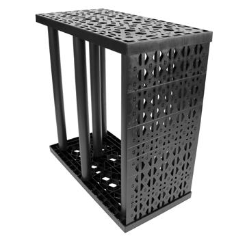
3 1.0 Introduction About Brentwood Brentwood is a global manufacturer of custom and proprietary products and systems for the construction, consumer, medical, power, transportation, and water industries. A focus on plastics innovation, coupled with diverse production capabilities and engineering expertise, has allowed Brentwood to build a strong reputation for thermoplastic molding and solutions development. Brentwood s product and service offerings continue to grow with an ever-increasing manufacturing presence. By emphasizing customer service and working closely with clients throughout the design, engineering, and manufacturing phases of each project, Brentwood develops forward-thinking strategies to create targeted, tailored solutions. StormTank Module The StormTank Module is a strong, yet lightweight, alternative to other subsurface systems and offers the largest void space (up to 97%) of any subsurface stormwater storage unit on the market. The Modules are simple to assemble on site, limiting shipping costs, installation time, and labor. Their structural PVC columns pressure fit into the polypropylene top/bottom platens, with side panels inserted around the perimeter of the system. This open design and lack of internal walls make the Module system easy to clean compared to other subsurface box structures. When properly designed, applied, installed, and maintained, the Module system has been engineered to achieve a 50-year lifespan. Technical Support Brentwood s knowledgeable distributor network and in-house associates emphasize customer service and support by parterning with customers to extend the process beyond physical material supply. These trained specialists are available to assist in the review of proposed systems, conversions of alternatively designed systems, or to resolve any potential concerns before, during, and after the design process. To provide the best assistance, it is recommended that associates be provided with a site plan and cross-sections that include grading, drainage structures, dimensions, etc. 3
4 2.0 Product Information Applications The Module system can be utilized for detention, infiltration, capture and reuse, and specialty applications across a wide range of industries, including the commercial, residential, and recreational segments. The product s modular design allows the system to be configured in almost any shape (even around utilities) and to be located under almost any pervious or impervious surface. Module Selection Brentwood manufactures the Module in five different heights (Table 1) that can be stacked uniformly up to two Modules high. This allows for numerous height configurations up to 6 (1.83 m) tall. The Modules can be buried up to a maximum invert of 11 (3.35 m) and require a minimum cover of 24 (610 mm) for load rating. When selecting the proper Module, it is important to consider the minimum required cover, any groundwater or limiting zone restrictions, footprint requirements, and all local, state, and federal regulations. Table 1: Nominal StormTank Module Specificiations ST-18 ST-24 ST-30 ST-33 ST-36 Height 18" (457 mm) 24 (610 mm) 30" (762 mm) 33 (838 mm) 36" (914 mm) Void Space 95.5% 96.0% 96.5% 96.9% 97.0% Module Storage Capacity 6.54 ft 3 (0.18 m 3 ) 8.64 ft 3 (0.24 m 3 ) ft 3 (0.31 m 3 ) ft 3 (0.34 m 3 ) ft 3 (0.37 m 3 ) Min. Installed Capacity* 9.15 ft 3 (0.26 m 3 ) ft 3 (0.32 m 3 ) ft 3 (0.38 m 3 ) ft 3 (0.42 m 3 ) ft 3 (0.45 m 3 ) Weight lbs (10.30 kg) lbs (11.93 kg) lbs (13.38 kg) 31.3 lbs (14.20 kg) lbs (15.01 kg) *Min. Installed Capacity includes the leveling bed, Module, and top backfill storage capacity for one Module. Stone storage capacity is based on 40% void space. Side backfill storage is not included. 4
, Brentwood selected polyvinyl chloride (PVC) for the Module s structural columns and a virgin polypropylene (PP) blend")
 and recycled PP have lower creep resistance and are not recommended for load-bearing products and applications.")


5 3.0 Manufacturing Standards Brentwood selects material based on long-term performance needs. To ensure longterm performance and limit component deflection over time (creep), Brentwood selected polyvinyl chloride (PVC) for the Module s structural columns and a virgin polypropylene (PP) blend for the top/bottom and side panels. PVC provides the largest creep resistance of commonly available plastics, and therefore, provides the best performance under loading conditions. Materials like polyethylene (HDPE) and recycled PP have lower creep resistance and are not recommended for load-bearing products and applications. Materials: Brentwood s proprietary PVC and PP copolymer resins have been chosen specifically for utilization in the StormTank Module. The PVC is blended in house by experts and is a 100% blend of post-manuacturing/pre-consumer recycled material. Both materials exhibit structural resilience and naturally resist the chemicals typically found in stormwater runoff. Methods: Injection Molding The Module s top/bottom platens and side panels are injection molded, using proprietary molds and materials. This allows Brentwood to manufacture a product that meets structural requirements while maintaining dimensional control, molded-in traceability, and quality control. Extrusion Brentwood s expertise in PVC extrusion allows the structural columns to be manufactured in house. The column extrusion includes the internal structural ribs required for lateral support. Quality Control Brentwood maintains strict quality control in order to ensure that materials and the final product meet design requirments. This quality assurance program includes full material property testing in accordance with American Society for Testing and Materials (ASTM) standards, full-part testing, and process testing in order to quantify product performance during manufacturing. Additionally, Brentwood conducts secondary finshed-part testing to verify that design requirements continue to be met post-manufacturing. All Module parts are marked with traceability information that allows for tracking of manufacturing. Brentwood maintains equipment at all manufacturing locations, as well as at its corporate testing lab, to ensure all materials and products meet all requirements. 5
 Bridge Design manual.")


6 4.0 Structural Response Structural Design The Module has been designed to resist loads calculated in accordance with the American Association of State Highway and Transportation Official s (AASHTO) Load and Resistance Factor Design (LRFD) Bridge Design manual. This fully factored load includes a multiple presence factor, dynamic load allowance, and live load factor to account for real-world situations. This loading was considered when Brentwood developed both the product and installation requirements. The developed minimum cover ensures the system maintains an adequate resistance factor for the design truck (HS-20) and HS-25 loads. Full-Scale Product Testing Engineers at Brentwood s in-house testing facility have completed full-scale vertical and lateral tests on the Module to evaluate product response. To date, Brentwood continues in-house testing in order to evaluate long-term creep effects. Fully Installed System Testing Brentwood s dedication to providing a premier product extends to fully installed testing. Through a partnership with Queen s University s GeoEngineering Centre in Kingston, Ontario, Brentwood has conducted full-scale installation tests of single- and double-stacked Module systems to analyze short- and long-term performance. Testing includes short-term ultimate limit state testing under fully factored AASHTO loads and minimum installation cover, lateral load testing, long-term performance and lifecycle testing utilizing timetemperature superposition, and load resistance development. Side backfill material tests were also performed to compare the usage of sand, compacted stone, and uncompacted stone. 6
7 5.0 Foundation The foundation (subgrade) of the subsurface storage structure may be the most important part of the Module system installation as this is the location where the system applies the load generated at the surface. If the subgrade lacks adequate support or encounters potential settlement, the entire system could be adversely affected. Therefore, when implementing an underground storage solution, it is imperative that a geotechnical investigation be performed to ensure a strong foundation. Considerations & Requirements: Bearing Capacity The bearing capacity is the ability of the soil to resist settlement. In other words, it is the amount of weight the soil can support. This is important versus the native condition because the system is replacing earth, and even though the system weighs less than the earth, the additional load displacement of the earth is not offset by the difference in weight. Using the Loading and Resistance Factor Design (LRFD) calculation for bearing capacity, Brentwood has developed a conservative minimum bearing capacity table (see Appendix). The Engineer of Record shall reference this table to assess actual cover versus the soil bearing required for each unit system. Limiting Zones Limiting zones are conditions in the underlying soils that can affect the maximum available depth for installation and can reduce the strength and stability of the underlying subgrade. The three main forms of limiting zones are water tables, bedrock, and karst topography. It is recommended that a system be offset a minimum of 12" (305 mm) from any limiting zones. Soil Profile Compaction Soil compaction occurs as the soil particles are pressed together and pore space is eliminated. By compacting the soils to 95% (as recommended by Brentwood), the subgrade strength will increase, in turn limiting both the potential for the soil to move once installed and for differential settlement to occur throughout the system. If designing the specific compaction requirement, settlement should be limited to less than 1 (25 mm) through the entire subgrade and should not exceed a 1/2 (13 mm) of differential settlement between any two adjacent units within the system over time. Mitigation If a minimum subgrade bearing capacity cannot be achieved because of weak soil, a suitable design will need to be completed by a Geotechnical Engineer. This design may include the overexcavation of the subgrade and an engineered fill or slurry being placed. Additional material such as geogrid or other products may also be required. Please contact a Geotechnical Engineer prior to selecting products or designing the subgrade. 7 Precipitation Soil Zone Recharge to Water Table Unsaturated Zone Water Table Capillary Fringe Saturated Zone Water Table Zones
8 6.0 System Materials Geotextile Fabric The 6-ounce geotextile fabric is recommended to be installed between the soil and stone interfaces around the Modules to prevent soil migration. Leveling Bed The leveling bed is constructed of 6 -thick (152 mm) angular stone (Table 2). The bed has not been designed as a structural element but is utilized to provide a level surface for the installation of the system and provide an even distribution of load to the subgrade. Stone Backfill The stone backfill is designed to limit the strain on the product through displacement of load and ensure the product s longevity. Therefore, a minimum of 12 -wide (305 mm) angular stone must be placed around all sides of the system. In addition, a minimum layer of 12 (305 mm) angular stone is required on top of the system. All material is to be placed evenly in 12 (305 mm) lifts around and on top of the system and aligned with a vibratory plate compactor. Table 2: Approved Backfill Material Material Location Description AASHTO M43 Designation ASTM D2321 Class Compaction/Density Finished Surface Topsoil, hardscape, stone, concrete, or asphalt per Engineer of Record N/A N/A Prepare per engineered plans Suitable Compactable Fill Well-graded granular soil/aggregate, typically road base or earthen fill (maximum 4" particle size) 56, 57, 6, 67, 68 I & II III (Earth Only) Place in maximum 12" lifts to a minimum 90% standard proctor density Top Backfill Crushed angular stone placed between Modules and road base or earthen fill 56, 57, 6, 67, 68 I & II Plate vibrate to provide evenly distributed layers Side Backfill Crushed angular stone placed between earthen wall and Modules 56, 57, 6, 67, 68 I & II Place and plate vibrate in uniform 12" lifts around the system Leveling Bed Crushed angular stone placed to provide level surface for installation of Modules 56, 57, 6, 67, 68 I & II Plate vibrate to achieve level surface Impermeable Liner In designs that prevent runoff from infiltrating into the surrounding soil (detention or reuse applications) or groundwater from entering the system, an impermeable liner is required. When incorporating a liner as part of the system, Brentwood recommends using a manufactured product such as a PVC liner. This can be installed around the Modules themselves or installed around the excavation (to gain the benefit of the void space in the stone) and should include an underdrain system to ensure the basin fully drains. This liner is installed with a layer of geotextile fabric on both sides to prevent puncture, in accordance with manufacturer recommendations. 8
9 7.0 Connections Stormwater runoff must be able to move readily in and out of the StormTank Module system. Brentwood has developed numerous means of connecting to the system, including inlet/outlet ports and direct abutment to a catch basin or endwall. All methods of connection should be evaluated as each one may offer a different solution. Brentwood has developed drawings to assist with specific installation methods, and these are available at Inlet/Outlet and Pipe Connections To facilitate easy connection to the system, Brentwood manufactures two inlet/outlet ports. They are 12 (305 mm) and 14 (356 mm), respectfully, and utilize a flexible coupling connection to the adjoining pipe. Another common installation method is to directly connect the pipe to the system. In order to do this, an opening is cut into the side panels, the pipe is inserted, and then the system is wrapped in geotextile fabric. When utilizing this connection method, the pipe must be located a minimum of 3 (76 mm) from the bottom of the system. This provides adequate clearance for the bottom platen and the required strength in the remaining side panel. To maintain the required clearances or reduce pipe size, it may be necessary to connect utilizing a manifold system. Direct Abutment The system can also be connected by directly abutting Modules to a concrete catch basin or endwall. This allows for a seamless connection of structures in close proximity to the system and eliminates the need for numerous pipe connections. When directly abutting one of these structures, remove any side panels that fully abut the structure, and make sure it is flush with the system to prevent material migration into the structure. Underdrain Underdrains are typically utilized in detention applications to ensure the system fully drains since infiltration is limited or prohibited. The incorporation of an underdrain in a detention application will require an impermeable liner between the stone-soil interface. Cleanout Ports Brentwood understands the necessity to inspect and clean a subsurface system and has designed the Module without any walls to allow full access. Brentwood offers three different cleanout/ observation ports for utilization with the system. The ports are made from PVC, provide an easy means of connection, and are available in 6 (152 mm), 8 (203 mm) and 10 (254 mm) diameters. The 10 (254 mm) port is sized to allow access to the system by a vacuum truck suction hose for easy debris removal. Air Flow Rising Water It is recommended that ports be located a maximum of 30 (9.14 m) on center to provide adequate access, ensure proper airflow, and allow the system to completely fill. Ventilation and Air Flow 9
10 8.0 Pretreatment Removing pollutants from stormwater runoff is an important component of any stormwater management plan. Pretreatment works to prevent water quality deterioration and also plays an integral part in allowing the system to maintain performance over time and increase longevity. Treatment products vary in complexity, design, and effectiveness, and therefore, should be selected based on specific project requirements. Typical Stormwater System Catch Basin Inlet Piping Pretreatment Storage Basin Outlet Structure StormTank Shield Brentwood s StormTank Shield provides a low-cost solution for stormwater pretreatment. Designed to improve sumped inlet treatment, the Shield reduces pollutant discharge through gross sediment removal and oil/water separation. For more information, please visit Debris Row (Easy Cleanout) An essential step of designing, installing, and maintaining a subsurface system is preventing debris from entering the storage. This can be done by incorporating debris rows (or bays) at the inlets of the system to prevent debris from entering the rest of the system. The debris row is built into the system utilizing side panels with a 12 (305 mm) segment of geotextile fabric. This allows for the full basin capacity to be utilized while storing any debris in an easy-to-remove location. To calculate the number of side panels required to prevent backing up, the opening area of the side panels on the area above the geotextile fabric has been calculated and compared to the inflow pipe diameter. Debris row cleanout is made easy by including 10 (254 mm) suction ports, based on the length of the row, and a 6 (152 mm) saddle connection to the inflow pipe. If the system is directly abutting a catch basin, the saddle connection is not required, and the flush hose can be inserted through the catch basin. Debris is then flushed from the inlet toward the suction ports and removed. Brentwood has developed drawings and specifications that are available at to illustrate the debris row configuration and layouts. CONCRETE COLLAR ACCESS BOX CONCRETE COLLAR ACCESS BOX 6" (152 mm) RISER 10" (254 mm) RISER INFLUENT WYE CONNECTION STORMTANK MODULE INFLUENT PIPE DEBRIS ROW PERIMETER SIDE PANELS 12" (305 mm) HIGH GEOTEXTILE DEBRIS FILTER (MIRAFI 135N OR APPROVED EQUAL) COLLECTED DEBRIS BUILDUP (SHOWN FOR CLARITY) Debris Row Section Detail 10

11 9.0 Additional Considerations Many variable factors, such as the examples below, must be taken into consideration when designing a StormTank Module system. As these considerations require complex calculations and proper planning, please contact Brentwood or your local distributor to discuss project-specific requirements. Adaptability The Modules can be arranged in custom configurations to meet tight site constraints and to provide different horizontal and edge configurations. Modules can also be stacked, to a maximum 2 units tall, to meet capacity needs and can be buried to a maximum invert of 11 (3.35 m) to allow for a stacked system or deeper burial. Adjacent Structures The location of adjacent structures, especially the location of footings and foundations, must be taken into consideration as part of system design. The foundation of a building or retaining wall produces a load Site Plan Module Layout Adaptability (StormTank Modules shown in blue) that is transmitted to a footing and then applied to the surface below. The footing is intended to distribute the line load of the wall over a larger area without increasing the larger wall s thickness. The reason this is important is because the load the footing is applying to the earth is distributed through the earth and could potentially affect a subsurface system as either a vertical load to the top of the Module or a lateral load to the side of the Module. Based on this increased loading, it is recommended that the subsurface system either maintain a distance away from the foundation, footing equal to the height between the Module invert and structure invert of the system, or the foundation or footing extend at a minimum to the invert of the subsurface system. By locating the foundation away from the system or equal to the invert, the loading generated by the structure does not get transferred onto the system. It is recommended that all adjacent structures be completed prior to the installation of the Modules to prevent construction loads from being imparted on the system. Adjacent Excavation The subsurface system must be protected before, during, and after the installation. Once a system is installed, it is important to remember that excavation adjacent to the system could potentially cause the system to become unstable. The uniform backfilling will evenly distribute the lateral loads to the system and prohibit the system from becoming unstable and racking from unequal loads. However, it is recommended that any excavation adjacent to a system remain a minimum distance away from the system equal to the invert. This will provide a soil load that is equal to the load applied by the opposite side of the installation. If the excavation is to exceed the invert of the system, additional analysis may be necessary. Sloped Finished Grade Much like adjacent excavation, a finished grade with a differential cover could potentially cause a subsurface system to become disproportionately loaded. For example, if one side of the system has 10 (3.05 m) of cover and the adjacent side has 24 (610 mm) of cover, the taller side will generate a higher lateral load, and the opposite side may not have an equal amount of resistance to prevent a racking of the system. Additional evaluation may be required when working on sites where the final grade around a system exceeds 5%. 11
12 10.0 Inspection & Maintenance Description Proper inspection and maintenance of a subsurface stormwater storage system are vital to ensuring proper product functioning and system longevity. It is recommended that during construction the contractor takes the necessary steps to prevent sediment from entering the subsurface system. This may include the installation of a bypass pipe around the system until the site is stabilized. The contractor should install and maintain all site erosion and sediment per Best Management Practices (BMP) and local, state, and federal regulations. Once the site is stabilized, the contractor should remove and properly dispose of erosion and sediment per BMP and all local, state, and federal regulations. Care should be taken during removal to prevent collected sediment or debris from entering the stormwater system. Once the controls are removed, the system should be flushed to remove any sediment or construction debris by following the maintenance procedure outlined below. During the first service year, a visual inspection should be completed during and after each major rainfall event, in addition to semiannual inspections, to establish a pattern of sediment and debris buildup. Each stormwater system is unique, and multiple criteria can affect maintenance frequency. For example, whether or not a system design includes inlet protection or a pretreatment device has a substantial effect on the system s need for maintenance. Other factors include where the runoff is coming from (hardscape, gravel, soil, etc.) and seasonal changes like autumn leaves and winter salt. During and after the second year of service, an established annual inspection frequency, based on the information collected during the first year, should be followed. At a minimum, an inspection should be performed semi-annually. Additional inspections may be required at the change of seasons for regions that experience adverse conditions (leaves, cinders, salt, sand, etc). Maintenance Procedures Inspection: 1. Inspect all observation ports, inflow and outflow connections, and the discharge area. 2. Identify and log any sediment and debris accumulation, system backup, or discharge rate changes. 3. If there is a sufficient need for cleanout, contact a local cleaning company for assistance. Cleaning: 1. If a pretreatment device is installed, follow manufacturer recommendations. 2. Using a vacuum pump truck, evacuate debris from the inflow and outflow points. 3. Flush the system with clean water, forcing debris from the system. 4. Repeat steps 2 and 3 until no debris is evident. 12
13 11.0 System Sizing System Sizing Calculation This section provides a brief description of the process required to size the StormTank Module system. If you need additional assistance in determining the required number of Modules or assistance with the proposed configuration, it is recommended that you contact Brentwood or your local distributor. Additionally, Brentwood s volume calculator can help you to estimate the available storage volumes with and without stone storage. This tool is available at 1. Determine the required storage volume (Vs): It is the sole responsibility of the Engineer of Record to calculate the storage volume in accordance with all local, state, and federal regulations. 2. Determine the required number of Modules (N): If the storage volume does not include stone storage, take the total volume divided by the selected Module storage volume. If the stone storage is to be included, additional calculations will be required to determine the available stone storage for each configuration. 3. Determine the required volume of stone (Vstone): The system requires a minimum 6 (152 mm) leveling bed, 12 (305 mm) backfill around the system, and 12 (305 mm) top backfill utilizing 3/4 (19 mm) angular clean stone. Therefore, take the area of the system times the leveling bed and the top backfill. Once that value is determined, add the volume based on the side backfill width times the height from the invert of the Modules to the top of the Modules. 4. Determine the required excavation volume (Vexcv): Utilizing the area of the system, including the side backfill, multiply by the depth of the system including the leveling bed. It is noted that this calculation should also include any necessary side pitch or benching that is required for local, state, or federal safety standards. 5. Determine the required amount of geotextile (G): The system utilizes a multiple layer system of geotextile fabric. Therefore, two calculations are required to determine the necessary amount of geotextile. The first layer surrounds the entire system (including all backfill), and the second layer surrounds the Module system only. It is recommended that an additional 20% be included for waste and overlap. 13
14 11.1 Storage Volume Stage Elevation (Inches) Total Total Total Total Total " Module 24" Module 30" Module 33" Module 36" Module Module Height 14
15 11.2 Material Quantity Worksheet Project Name: By: Location: Date: System Requirements Required Storage Number of Modules Module Storage Stone Storage Module Footprint System Footprint w/ Stone Stone Volume of Excavation Area of Geotextile ft 3 (m 3 ) Each ft 3 (m 3 ) ft 3 (m 3 ) ft 2 (m 2 ) Number of Modules x 4.5 ft 2 (0.42 m 2 ) ft 2 (m 2 ) Module Footprint + 1 ft ( m) to each edge Tons (kg) Leveling Bed + Side Backfill + Top Backfill yd 3 (m 3 ) System Footprint w/ Stone x Total Height yd 2 (m 2 ) Wrap around Modules + Wrap around Stone/Soil Interface System Cost Quantity Unit Price Total Modules ft 3 (m 3 ) X $ ft 3 (m 3 ) = $ Stone Tons (kg) X $ Tons (kg) = $ Excavation yd 3 (m 3 ) X $ yd 3 (m 3 ) = $ Geotextile yd 2 (m 2 ) X $ yd 2 (m 2 ) = $ Subtotal = Tons = $ $ Material costs may not include freight. Please contact Brentwood or your local distributor for this information. 15


16 12.0 Detail Drawings Brentwood has developed numerous drawings for utilization when specifying a StormTank Module system. Below are some examples of drawings available at 16
17 13.0 Specifications 1) General a) This specification shall govern the implementation, performance, material, and fabrication pertaining to the subsurface stormwater storage system. The subsurface stormwater storage system shall be manufactured by Brentwood Industries, Inc., 500 Spring Ridge Drive, Reading, PA ( ), and shall adhere to the following specification at the required storage capacities. b) All work is to be completed per the design requirements of the Engineer of Record and to meet or exceed the manufacturer s design and installation requirements. 2) Subsurface Stormwater Storage System Modules a) The subsurface stormwater storage system shall be constructed from virgin polypropylene and 100% recycled PVC to meet the following requirements: i) High-Impact Polypropylene Copolymer Material (1) Injection molded, polypropylene, top/bottom platens and side panels formed to a dimension of 36 (914 mm) long by 18 (457 mm) wide [nominal]. ii) 100% Recycled PVC Material (1) PVC conforming to ASTM D-1784 Cell Classification b B. (2) Extruded, rigid, and 100% recycled PVC columns sized for applicable loads as defined by Section 3 of the AASHTO LRFD Bridge Design Specifications and manufactured to the required length per engineer-approved drawings. iii) Platens and columns are assembled on site to create Modules, which can be uniformly stacked up to two Modules high, in vertical structures of variable height (custom for each project). iv) Modular stormwater storage units must have a minimum 95% void space and be continuously open in both length and width, with no internal walls or partitions. 3) Submittals a) Only systems that are approved by the engineer will be allowed. b) At least 10 days prior to bid, submit the following to the engineer to be considered for pre-qualification to bid: i) A list of materials to be provided for work under this article, including the name and address of the materials producer and the location from which the materials are to be obtained. ii) Three hard copies of the following: (1) Shop drawings. (2) Specification sheets. (3) Installation instructions. (4) Maintenance guidelines. c) Subsurface Stormwater Storage System Component Samples for review: i) Subsurface stormwater storage system Modules provide a single 36 (914 mm) long by 18 (457 mm) wide, height as specified, unit of the product for review. ii) Sample to be retained by owner. d) Manufacturers named as acceptable herein are not required to submit samples. 4) Structural Design a) The structural design, backfill, and installation requirements shall ensure the loads and load factors specified in the AASHTO LRFD Bridge Design Specifications, Section 3 are met. b) Product shall be tested under minimum installation criteria for short-duration live loads that are calculated to include a 20% increase over the AASHTO Design Truck standard with consideration for impact, multiple vehicle presences, and live load factor. c) Product shall be tested under maximum burial criteria for long-term dead loads. d) The engineer may require submission of third-party test data and results in accordance with items 4b and 4c to ensure adequate structural design and performance. 17
18 14.0 Appendix - Bearing Capacity Tables English (in) Cover HS-25 (Unfactored) HS-25 (Factored) Metric (mm) English (ksf) Metric (kpa) English (ksf) Metric (kpa) , , , , , , , , , , , , , , , , , , , , , , , , , , , , , , English (in) Cover HS-25 (Unfactored) HS-25 (Factored) Metric (mm) English (ksf) Metric (kpa) English (ksf) Metric (kpa) 70 1, , , , , , , , , , , , , , , , , , , , , , , , , , , , , , , , , , , , , , , , , , , , ,
19 BRENTWOOD INDUSTRIES, INC. brentwoodindustries.com All Rights Reserved Brentwood Industries, Inc. 19 SM002-1_09-14_EN
4.8. Subsurface Infiltration
 4.8. Subsurface Infiltration Subsurface infiltration systems are designed to provide temporary below grade storage infiltration of stormwater as it infiltrates into the ground. Dry wells, infiltration
4.8. Subsurface Infiltration
 4.8. Subsurface Infiltration Subsurface infiltration systems are designed to provide temporary below grade storage infiltration of storm water as it infiltrates into the ground. Dry wells, infiltration
MC-3500 and MC-4500 Design Manual
 MC-3500 / MC-4500 MC-3500 and MC-4500 Design Manual StormTech Chamber Systems for Stormwater Management Table of Contents 1.0 Product Information...2 2.0 Foundations for Chambers...8 3.0 Required Materials/Row
BMP 6.4.4: Infiltration Trench
 BMP 6.4.4: Infiltration Trench An Infiltration Trench is a leaky pipe in a stone filled trench with a level bottom. An Infiltration Trench may be used as part of a larger storm sewer system, such as a
SECTION SPECIFICATION FOR STONEBRIDGE RETAINING WALL SYSTEM
 SECTION 32 32 23 SPECIFICATION FOR STONEBRIDGE RETAINING WALL SYSTEM PART 1: GENERAL 1.01 Scope Work includes furnishing all materials, labor, equipment, and supervision to install a Stonebridge segmental
StormTech Construction Guide
 A division of StormTech solid end caps and pre-cored end caps StormTech chambers StormTech manifolds and fittings Acceptable fill materials per Table 1 Woven and non-woven geotextiles 80-7 DC REQUIRED
R-TANK SPECIFICATIONS
 TECHNICAL STORMWATER MANAGEMENT R-TANK SPECIFICATIONS PART 1 GENERAL 1.01 Related Documents A. Drawings, technical specification and general provisions of the Contract as modified herein apply to this
CULTEC STORMWATER CHAMBER SYSTEMS
 DRAINAGE SOLUTIONS SINCE 1908 CULTEC STORMWATER CHAMBER SYSTEMS RETENTION / DETENTION / INFILTRATION ENVIRONMENTAL PROTECTION COST-EFFECTIVE LAND USE EASY TO INSTALL ARMTEC.COM CULTEC STORMWATER MANAGEMENT
Product Catalogue. Not intended for design layouts; refer to the appropriate StormTech Design Manual for specific chamber design information.
 Product Catalogue Not intended for design layouts; refer to the appropriate Design Manual for specific chamber design information. Subsurface Stomwater Management Specifications and Product Comparison
SUBSURFACE INFILTRATION SYSTEM DESCRIPTION. Alternative Names: Sump, Drywell, Infiltration Trench, Infiltration Galleries, Leach Fields
 4.1-d SUBSURFACE INFILTRATION SYSTEM Alternative Names: Sump, Drywell, Infiltration Trench, Infiltration Galleries, Leach Fields BMP DESIGN APPROACH Pollutant Source Control Hydrologic Source Control Stormwater
SPECIFICATIONS FOR PRECAST MODULAR BLOCK RETAINING WALL SYSTEM (revised 5/8/7)
") Page 1 of 7 STONE STRONG SYSTEMS SPECIFICATIONS FOR PRECAST MODULAR BLOCK RETAINING WALL SYSTEM (revised 5/8/7) PART 1: GENERAL 1.01 Description A. Work includes furnishing and installing precast modular
Page 1 of 7 STONE STRONG SYSTEMS SPECIFICATIONS FOR PRECAST MODULAR BLOCK RETAINING WALL SYSTEM (revised 5/8/7) PART 1: GENERAL 1.01 Description A. Work includes furnishing and installing precast modular
StormTech Product Catalogue
 StormTech Product Catalogue The Most Advanced Name in Drainage Systems StormTech Subsurface Stomwater Management Table of Contents Subsurface Stormwater Management...2 Specifications and Product Comparison...3
Fabrication and Installation Table of Contents
 Fabrication and Installation Table of Contents HDPE AQUASHIELD PRODUCTS 2 Fabrication and Installation 2 System Fabrication 3 Aqua-Swirl Installation 4 Step 1 Excavation and Bedding 4 Step 2 Pipe Connection
SECTION FOUNDATION DRAINAGE
 SECTION 33 41 13 SPEC WRITER NOTES: Use this section only for NCA projects. Delete text between // // not applicable to project. Edit remaining text to suit project. PART 1 - GENERAL 1.1 SUMMARY A. Section
ENGINEERED SOLUTIONS. Terre Arch Concrete Detention/Infiltration. Solutions Guide
 ENGINEERED SOLUTIONS Terre Arch Concrete Detention/Infiltration Solutions Guide Stormwater Solutions from Contech Selecting the Right Stormwater Solution Just Got Easier... It s simple to choose the right
SECTION PERMEABLE INTERLOCKING CONCRETE UNIT PAVEMENT
 SECTION 32 14 13 19 PERMEABLE INTERLOCKING CONCRETE UNIT PAVEMENT SECTION 32 14 13 19 PERMEABLE INTERLOCKING CONCRETE UNIT PAVEMENT PART 1 - GENERAL 1.1 SUMMARY A. Section Includes: 1. Permeable Articulating
Construction Inspection Checklists
 III. Construction Inspection Checklists 33 Bioretention - Construction Inspection Checklist Project: Location: Site Status: Date: Time: Inspector: Construction Sequence Satisfactory / Unsatisfactory Comments
PERMEABLE INTERLOCKING PAVERS
 PERMEABLE INTERLOCKING PAVERS PART 1 - GENERAL 1.01 SECTION INCLUDES A. Subgrade Preparation B. Placement of Storage Aggregate C. Placement of Filter Aggregate D. Placement of Bedding Course E. Placement
C. Foundation stabilization for pipe and utility structures.
 PART 1 - GENERAL 1.1 SECTION INCLUDES A. Excavating, backfilling, and compacting for utilities, including pipe, structures, and appurtenances. B. Control of water in trenches. C. Foundation stabilization
B. Install storm drain inlet protection to prevent clogging of the stormsewer and sediment loads to downstream stormwater facilities or waterbodies.
 The language provided in these specifications is meant to serve as a reminder and provide a generic example of the type of language that should be provided in final construction documents. This language
Ohio Department of Transportation Division of Production Management Office of Geotechnical Engineering. Geotechnical Bulletin
 Ohio Department of Transportation Division of Production Management Office of Geotechnical Engineering Geotechnical Bulletin GB 2 SPECIAL BENCHING AND SIDEHILL EMBANKMENT FILLS Geotechnical Bulletin GB2
Section 1I-3 - Bioswales
 BIOSWALES (Numbering pending) These specifications compliment the bioswale design portion of the Iowa Stormwater Management Manual in Chapter 2, Section 2I-3. Sections of the following documents, as referenced
ITEM D-701 PIPE FOR STORM DRAINS AND CULVERTS
 ITEM D-701 PIPE FOR STORM DRAINS AND CULVERTS 701-1 DESCRIPTION 701-1.1 This item shall consist of the construction of pipe culverts, and storm drains, removal of existing storm pipes, connections to existing
CHAPTER 6. Sanitary Sewer
 CHAPTER 6 Sanitary Sewer A. Introduction All proposed developments, subdivisions, and buildings must have a properly designed and constructed sanitary sewer collection system. The system shall provide
Design Manual StormTech. Chamber Systems for Stormwater Management
 Design Manual StormTech Chamber Systems for Stormwater Management Table of Contents 1.0 Introduction...2 2.0 Product Information...3 3.0 Structural Capabilities...6 4.0 Foundation for Chambers...8 5.0
Uwall UNIVERSAL CONSTRUCTION MANUAL
 Uwall UNIVERSAL Retaining Wall System CONSTRUCTION MANUAL TM President s Letter CSI is a leader in its industry supplying precast infrastructure products throughout New England and beyond since 1972, developing
CONCRETE SEGMENTAL RETAINING WALL SYSTEM
 CONCRETE SEGMENTAL RETAINING WALL SYSTEM PART 1: GENERAL SPECIFICATIONS 1.01 Work Included A. Work shall consist of furnishing and constructing a Rockwood Classic 8, Classic 6 and Legend unit segmental
SECTION 19 - TRENCH EXCAVATION, BEDDING AND BACKFILL TABLE OF CONTENTS
 SECTION 19 - TRENCH EXCAVATION, BEDDING AND BACKFILL TABLE OF CONTENTS Section Page 19-1 TRENCH EXCAVATION...19.1 19-1.01 Exploratory Excavation...19.1 19-1.02 Trench Width...19.1 19-1.02.A Storm Drain
PERVIOUS PAVEMENT. Alternative Names: Permeable Pavement, Porous Concrete, Porous Pavers
 4.1-a PERVIOUS PAVEMENT Alternative Names: Permeable Pavement, Porous Concrete, Porous Pavers DESCRIPTION Pervious pavement is any system comprised of a load bearing surface that allows for movement of
SECTION 1 BIO-INFILTRATION BUMP OUTS (BIBO)
") SECTION 1 BIO-INFILTRATION BUMP OUTS (BIBO) This guide specification for U.S. applications describes construction of bio-infiltration bump outs (or bioretention ) systems. From the surface down to the
SECTION 1 BIO-INFILTRATION BUMP OUTS (BIBO) This guide specification for U.S. applications describes construction of bio-infiltration bump outs (or bioretention ) systems. From the surface down to the
SECTION STORM UTILITY DRAINAGE PIPING PART 1 - GENERAL 1.1 SUMMARY 1.2 SUBMITTALS 1.3 PROJECT CONDITIONS
 SECTION 334100 - STORM UTILITY DRAINAGE PIPING PART 1 - GENERAL 1.1 SUMMARY Section Includes: 1. Pipe and fittings. 2. Drain Basin. 3. De-chlorination tablet feeder. 4. Non-pressure transition couplings.
B. Subsurface data is available from the Owner. Contractor is urged to carefully analyze the site conditions.
 SECTION 31 23 33 - TRENCHING, BACKFILLING AND COMPACTION PART 1 - GENERAL 1.1 SCOPE A. This Section specifies the requirements for excavating and backfilling for storm sewer, sanitary sewer, water distribution
A. This Section includes subdrainage systems for foundations and underslab areas. A. Product Data: For each type of drainage panel indicated.
 ZGF Partnership Page 1 of 7 SECTION 33 46 00 - PART 1 - GENERAL 1.1 SUMMARY A. This Section includes subdrainage systems for foundations and underslab areas. 1.2 SUBMITTALS A. Product Data: For each type
BIG O HDPE TUBING HDPE CORRUGATED TUBING FOR AGRICULTURAL, RESIDENTIAL AND HIGHWAY DRAINAGE INCREASE CROP YIELDS LOWER PRODUCTION COSTS
 DRAINAGE SOLUTIONS SINCE 1908 BIG O HDPE TUBING HDPE CORRUGATED TUBING FOR AGRICULTURAL, RESIDENTIAL AND HIGHWAY DRAINAGE INCREASE CROP YIELDS LOWER PRODUCTION COSTS PROTECT FOUNDATIONS IMPROVE HIGHWAY
BMP #: Infiltration Basin
 Structural BMP Criteria BMP #: Infiltration Basin An Infiltration Basin is a shallow impoundment that stores and infiltrates runoff over a level, subtle, uncompacted, (preferably undisturbed area) with
STORMCAPTURE. Installation Manual
 STORMCAPTURE Installation Manual Introduction Site Preparation Delivery & Installation LinkSlabs Backfill Introduction StormCapture (shown in Figure 1) is a total stormwater management system. The highly-configurable
Stormwater Local Design Manual For Houston County, Georgia
 Stormwater Local Design Manual For Houston County, Georgia Adopted November 15, 2005 TABLE OF CONTENTS 1. FORWARD... 1 2. GENERAL LEVEL OF SERVICE STANDARDS... 2 2.1. DETENTION REQUIREMENTS... 2 2.1.1.
StormwaterWise Landscapes: Pervious Surfaces Specifications
 StormwaterWise Landscapes: Pervious Surfaces Specifications Purpose & Benefits Stormwater runoff reduction High pollutant removal Control localized drainage problems Attractive alternative for walkways
SECTION 19 - TRENCH EXCAVATION, BEDDING AND BACKFILL TABLE OF CONTENTS
 SECTION 19 - TRENCH EXCAVATION, BEDDING AND BACKFILL TABLE OF CONTENTS Section Page 19-1 TRENCH EXCAVATION... 19.1 19-1.01 Exploratory Excavation... 19.1 19-1.02 Trench Width... 19.1 19-1.02.A Storm Drain
Special Provision No. 405F03 March 2005
 PIPE SUBDRAINS - Item No. VIDEO CAMERA INSPECTION Item No. Special Provision No. 405F03 March 2005 OPSS 405, February 1990, Construction Specification for Pipe Subdrains is deleted in its entirety and
MODEL Stormwater Local Design Manual. City of Centerville
 MODEL Stormwater Local Design Manual City of Centerville Adopted December 6, 2005 TABLE OF CONTENTS 1. FORWARD... 1 2. GENERAL LEVEL OF SERVICE STANDARDS... 1 2.1. DETENTION REQUIREMENTS... 1 2.1.1. Discharge
A detailed guide and sizing manual for the application of Silva Cells to meet the requirements of bioretention under paving.
 A detailed guide and sizing manual for the application of Silva Cells to meet the requirements of bioretention under paving. Materials specifications provided are based on general recommendations and can
SECTION TRENCHING & BACKFILLING
 SECTION 02225 - TRENCHING & BACKFILLING 1.0 GENERAL 1.1 Work included in this Section includes trenching and backfilling for underground pipelines and related structures only. 1.2 Reference Specifications
Section 401. PIPE CULVERTS
 401.02 Section 401. PIPE CULVERTS 401.01. Description. This work consists of constructing pipe culverts of the size and class required, including excavation and backfill. 401.02. Materials. Provide materials
SECTION EXCAVATION AND EMBANKMENT. B. Subbase Grading A samples for gradation analysis.
 PART 1 GENERAL 1.1 DESCRIPTION A. The WORK under this Section includes providing all labor, materials, tools and equipment necessary for excavation and embankment construction to the lines, grades and
CONSTRUCTION STANDARDS SECTION CS 3 TRENCH FOUNDATION, BEDDING AND BACKFILL
 CONSTRUCTION STANDARDS SECTION CS 3 TRENCH FOUNDATION, BEDDING AND BACKFILL CS 3-01 GENERAL: A. The foundation, bedding and backfill for all trenches shall conform with the requirements of the City Standard
LANDSCAPE RETAINING WALLS
 SUDAS Standard Specifications Division 9 - Site Work and Landscaping Section 9070 - Landscape Retaining Walls LANDSCAPE RETAINING WALLS PART - GENERAL.0 SECTION INCLUDES A. Modular Block Retaining Walls
Town of Essex, Vermont January, 2017 Standard Specifications For Construction CHAPTER 3 EROSION AND SEDIMENT CONTROL
 CHAPTER 3 EROSION AND SEDIMENT CONTROL CHAPTER 3 EROSION AND SEDIMENT CONTROL Section 300 General Summary All projects constructed within the Town of Essex shall be constructed in strict accordance with
Summary of the 2011 Changes
 The following is a list of amendments to the Residential Site Improvement s, N.J.A.C. 5:21, adopted in 2011. The Notice of Adoption of these changes appeared in the New Jersey Register on May 16, 2011.
AEC Premier Straw Double Net Quick Mow EROSION CONTROL BLANKET SPECIFICATION
 AEC Premier Straw Double Net Quick Mow EROSION CONTROL BLANKET SPECIFICATION PART I - GENERAL 1.01 Summary A. The erosion control blanket contains agricultural straw fibers for the purpose of erosion control
Section (02830) MODULAR CONCRETE RETAINING WALL
 MODULAR CONCRETE RETAINING WALL") Section 323223 (02830) MODULAR CONCRETE RETAINING WALL PART 1: GENERAL 1.01 Description A. Work shall consist of furnishing and constructing a VERDURA Retaining Wall System (or approved equal) in accordance
Section 323223 (02830) MODULAR CONCRETE RETAINING WALL PART 1: GENERAL 1.01 Description A. Work shall consist of furnishing and constructing a VERDURA Retaining Wall System (or approved equal) in accordance
Attachment D-1: Civil/Structural Scope of Work
 Attachment D-1: Civil/Structural Scope of Work Project: Location: Targa Sound Renewable Fuels Project Tacoma, WA Prepared by: NORWEST ENGINEERING Consulting Engineers 4110 N.E. 122 nd Avenue, Portland,
Anchorplex retaining wall construction guide. Building. Anchorplex. Retaining Wall Systems
 Anchorplex retaining wall construction guide Building Anchorplex Retaining Wall Systems Table of Contents and ow to Use This Guide table of contents ow to Use This Guide. 2 About the Anchorplex System.
PERMEABLE PAVERS PHYSICAL AND GEOMETRICAL CHARACTERISTICS - PAVERS DRIVEWAYS, PERMEABLE DRIVEWAYS & PATIOS CHARACTERISTICS CSA A231.
 DRIVEWAYS, DRIVEWAYS & PATIOS PHYSICAL AND GEOMETRICAL CHARACTERISTICS - CHARACTERISTICS CSA A231.2 TECHO-BLOC Compressive strength 50 MPa [7200 psi] min. 50 MPa [7200 psi] min. Absorption - 5 % max. Freeze-thaw
SEGMENTAL BLOCK RETAINING WALLS. Comply with Division 1 - General Provisions and Covenants, as well as the following:
 SEGMENTAL BLOCK RETAINING WALLS PART 1 - GENERAL 1.01 SECTION INCLUDES Segmental Block Retaining Walls 1.02 DESCRIPTION OF WORK Constructing segmental block retaining walls. 1.03 SUBMITTALS Comply with
BIOPOD TM BIOFILTER WITH STORMMIX BIOFILTRATION MEDIA. Inspection and Maintenance Guide
 BIOPOD TM BIOFILTER WITH STORMMIX TM BIOFILTRATION MEDIA Inspection and Maintenance Guide BioPod Biofilter with StormMix Biofiltration Media Description The BioPod Biofilter System (BioPod) is a stormwater
SPECIAL SPECIFICATION 3504 Septic Tank System
 1993 Specifications CSJ s 3136-01-126, etc. & 0683-01-070, etc. SPECIAL SPECIFICATION 3504 Septic Tank System 1. Description. This Item shall govern for all materials, equipment and labor necessary for
MACHINE-LAY Installation Manual
 MACHINE-LAY Installation Manual PaveDrain Installation Manual Table of Contents Section 1: Base Preparation (pages 3 6) Section 2: Machine-Lay PaveDrain Blocks (pages 8 11) Section 3: Edge Restraints (pages
EXCAVATION & BACKFILLING GUELPH TRANSIT OPERATIONS & MAINTENANCE SECTION WATSON ROAD FACILITY PAGE 1 OF 6 WATER RECLAMATION PROJECT JUNE 2013
 GUELPH TRANSIT OPERATIONS & MAINTENANCE SECTION WATSON ROAD FACILITY PAGE 1 OF 6 PART 1 GENERAL 1.1 Description The Work of this Section shall be all labour, materials, equipment and supervision necessary
Table of Contents AQUA-SWIRL 2
 Table of Contents AQUA-SWIRL 2 STORMWATER TREATMENT SOLUTIONS 2 System Operation 2 Custom Applications 4 Retrofit Applications 4 Installation 5 Buoyancy 5 Traffic Loading 6 Inspection and Maintenance 6
CHAPTER 200 STORM SEWER CONSTRUCTION STANDARDS
 CHAPTER 200 STORM SEWER CONSTRUCTION STANDARDS Storm Sewer System: 1. Detention/retention of stormwater runoff shall be provided in accordance with the requirements of the DuPage County Countywide Stormwater
PROJECT AT THE DENVER
 POROUS ASPHALT DEMONSTRATION PROJECT AT THE DENVER WASTEWATER BUILDING Ken A. MacKenzie, P.E. Manager, Master Planning Program Urban Drainage and Flood Control District 36 th Annual Rocky Mountain Asphalt
BIO-AQUIFER STORM SYSTEM
 BIO-AQUIFER STORM SYSTEM Specifications for Construction PART 1 GENERAL 1.01 SECTION INCLUDES A. Providing labor, materials, tools and equipment to furnish and install a permeable concrete paving stone
Rainwater Harvesting Tank
 ESTLISHED IN 1986 Rainwater Harvesting Tank ssembly and Installation Guide www.atlantiscorp.com.au Tank Module ssembly Guide Rainwater Harvesting Tank ssembly & Installation Guide 2 ssemble Matrix Tank
Boise City Public Works General Drainage Plan Review Requirements Checklist
 Boise City Public Works General Drainage Plan Review Requirements Checklist Development Name Bldg. Permit # Drainage Reviewer Site Address Initial Review Date ODI Number Designer Company Name Treated Acres
PVC Fittings & Laterals for Solid-Wall PVC Sewer Pipe
 Design and Installation Guide PVC Fittings & Laterals for Solid-Wall PVC Sewer Pipe TABLE OF CONTENTS Introduction 2 Products 3 Main-Line Fittings & Service-Line Fittings 3-4 Connections to Dissimilar
BAYFILTER SPECIFICATIONS
 PART 1.00 GENERAL 1.1 DESCRIPTION BAYFILTER SPECIFICATIONS A. The BayFilter system s internal components manufacturer selected by the Contractor and approved by the Engineer, shall furnish all labor, materials,
SECTION STORM DRAINAGE DESIGN, GRADING, AND WATER QUALITY TECHNICAL CRITERIA TABLE OF CONTENTS PAGE 402 STORM DRAINAGE DESIGN CRITERIA 400-1
 CITY OF THORNTON Standards and Specifications Revised: October 2012 SECTION 400 - STORM DRAINAGE DESIGN, GRADING, AND WATER QUALITY TECHNICAL CRITERIA TABLE OF CONTENTS PAGE 401 GENERAL PROVISIONS 400-1
THE MOST ADVANCED NAME IN WATER MANAGEMENT SOLUTIONS THERMOPLASTIC LINERS FOR DETENTION SYSTEMS
 THE MOST ADVANCED NAME IN WATER MANAGEMENT SOLUTIONS THERMOPLASTIC LINERS FOR DETENTION SYSTEMS STORMTECH VERSATILITY StormTech chambers offer the versatility to be designed as 1) retention systems, 2)
Bio-Filter TM Stormwater Biofiltration System
 Bio-Filter TM Stormwater Biofiltration System Inspection and Maintenance Manual March 2017 AquaShield, TM Inc. 2733 Kanasita Drive, Suite 111 Chattanooga, TN 37343 Phone: (423) 870-8888 Fax: (423) 826-2112
DESIGNING AND CONSTRUCTION OF T-WALL RETAINING WALL SYSTEM
 Istanbul Bridge Conference August 11-13, 2014 Istanbul, Turkey DESIGNING AND CONSTRUCTION OF T-WALL RETAINING WALL SYSTEM T. C. NEEL and K.BOZKURT ABSTRACT This work shall consist of the design, manufacture
PASSAIC COUNTY TECHNICAL INSTITUTE CCA 1422 NEW S.T.E.M. BUILDING 2017
 SECTION 02630 - STORM DRAINAGE PART 1 - GENERAL 1.1 RELATED DOCUMENTS A. Drawings and general provisions of the Contract, including General and Supplementary Conditions and Division 01 Specification Sections,
Rhode Island Stormwater Design and Installation Standards Manual
 Rhode Island Stormwater Design and Installation Standards Manual Public Workshop Infiltration (Including Permeable Paving) March 24, 2011 Infiltration Section 5.3: Appendix F.3 & H.1 Approved WQ BMPs Infiltration
Section ( ) SPECIFICATION FOR SEGMENTAL CONCRETE UNIT RETAINING WALL
 SPECIFICATION FOR SEGMENTAL CONCRETE UNIT RETAINING WALL") Section 02834 (32 32 23) SPECIFICATION FOR SEGMENTAL CONCRETE UNIT RETAINING WALL PART 1: GENERAL 1.01 Description A. Work shall consist of furnishing and construction of a County Materials Retaining Wall
Section 02834 (32 32 23) SPECIFICATION FOR SEGMENTAL CONCRETE UNIT RETAINING WALL PART 1: GENERAL 1.01 Description A. Work shall consist of furnishing and construction of a County Materials Retaining Wall
Presentation to the 60 th Annual NJ Asphalt Paving Conference March 14, 2017 Ewing, NJ
 Presentation to the 60 th Annual NJ Asphalt Paving Conference March 14, 2017 Ewing, NJ James J. Purcell, PE, PMP Technical Director, New Jersey Asphalt Pavement Association Reduce impervious surface Recharge
PART 3 - STANDARDS FOR SEWERAGE FACILITIES DESIGN OF STORM SEWERS
 PART 3 - STANDARDS FOR SEWERAGE FACILITIES 3.3 - DESIGN OF STORM SEWERS 3.301 Design of Storm Sewers A. General Information B. Investigations and Surveys C. Special Projects 3.302 Design Criteria for Storm
SECTION FACILITY SANITARY SEWERS
 SECTION 22 13 13 FACILITY SANITARY SEWERS PART 1 - GENERAL 1.1 RELATED DOCUMENTS A. Drawings and general provisions of the Contract, including General and Supplementary Conditions and Division 01 Specification
SITE SERVICES GUELPH TRANSIT OPERATIONS & MAINTENANCE SECTION WATSON ROAD FACILITY PAGE 1 OF 6 WATER RECLAMATION PROJECT JUNE 2013
 WATSON ROAD FACILITY PAGE 1 OF 6 PART 1 GENERAL 1.1 Description The work covered by this Section includes all labour, materials, equipment, and supervision necessary to complete the site services as shown
Curlex II EROSION CONTROL BLANKET SPECIFICATION
 Curlex II EROSION CONTROL BLANKET SPECIFICATION PART I - GENERAL 1.01 Summary A. The erosion control blanket contains excelsior wood fiber for the purpose of erosion control and revegetation as described
MODULAR CONCRETE RETAINING WALL
 MODULAR CONCRETE RETAINING WALL PART 1: GENERAL 1.01 Description A. Work shall consist of furnishing and construction of a KEYSTONE Retaining Wall System or equal in accordance with these specifications
SECTION STORM DRAINAGE AND STORMWATER MANAGEMENT
 SECTION 322 - STORM DRAINAGE AND STORMWATER MANAGEMENT 322.01 DESCRIPTION Work includes all labor, material and equipment to construct storm drain systems and stormwater management facilities, including
CETCO-VOLCLAY CG-50 SPECIFICATION GUIDELINES MIX IN PLACE
 CETCO-VOLCLAY CG-50 SPECIFICATION GUIDELINES MIX IN PLACE 1.0 GENERAL 1.1 Scope A. This specification guideline covers the technical requirements for furnishing all labor, materials, equipment, and incidentals
LAYING IBSTOCK CLAY PAVERS FOR PERMEABLE PAVEMENTS
 PERMEABLE PAVEMENTS (SUDS) This leaflet highlights the basic requirements for laying Ibstock clay pavers to form a permeable pavement. Ibstock clay pavers are intended for domestic use only i.e. patios
COMPACTED CLAY LINERS
 Technical Reference Document for Liquid Manure Storage Structures COMPACTED CLAY LINERS Table of Contents SECTION 1 - PURPOSE AND SCOPE 1.1. Purpose of the Technical Reference Document 1.2. Requirement
TRITON STORMWATER CHAMBERS & CULVERTS
 TRITON STORMWATER CHAMBERS & CULVERTS DATA SHEETS INDEX PAGE No. TRITON CHAMBER PRODUCTS 3 TRITON CHAMBERS AND CULVERTS 10 TRITON CHAMBER COMPARISON WITH OTHERS AND TRITON SOY RESIN MATERIAL PROPERTIES
Infiltration Guidelines
 Appendix E Infiltration Guidelines As a stormwater management method, infiltration means retaining or detaining water within soils to reduce runoff. Infiltration can be a cost-effective method to manage
STANDARD SPECIFICATION STORMWATER QUALITY MEMBRANE FILTRATION TREATMENT DEVICE
 STANDARD SPECIFICATION STORMWATER QUALITY MEMBRANE FILTRATION TREATMENT DEVICE PART 1 GENERAL 1.1 WORK INCLUDED Specifies requirements for construction and performance of an underground stormwater quality
Aqua-Swirl Stormwater Treatment System
 Aqua-Swirl Stormwater Treatment System Inspection and Maintenance Manual AquaShield, Inc. 2705 Kanasita Drive, Chattanooga, TN 37343 Phone: (423) 870-8888 Fax: (423) 826-2112 Email: info@aquashieldinc.com
BASED ON DFD MASTER SPECIFICATION DATED 2/24/2014
 1 0 1 0 1 0 1 SECTION 1. TRENCHING BASED ON DFD MASTER SPECIFICATION DATED // P A R T 1 - G E N E R A L SCOPE The work under this section shall consist of providing all work, materials, labor, equipment,
Construction Procedures
 Construction Procedures 2014 Rev. 1.6 1 Introduction This manual presents the methods and procedures necessary for the proper erection of a LOCK+LOAD retaining wall. problems later during the service life
Section Storm Sewers STORM SEWERS PART 1 - GENERAL 1.01 SECTION INCLUDES. A. Storm Sewers. B. Abandonment of Storm Sewers
 STORM SEWERS PART 1 - GENERAL 1.01 SECTION INCLUDES A. Storm Sewers B. Abandonment of Storm Sewers 1.02 DESCRIPTION OF WORK A. Construct storm sewers. B. Abandon storm sewers. 1.03 SUBMITTALS Comply with
Contact the Jurisdictional Engineer for materials allowed by each jurisdiction.
 Design Manual Chapter 3 - Sanitary Sewers 3C - Facility Design 3C-1 Facility Design A. Capacity of Pipe Pipe sizes 15 inches and smaller should carry the peak flow at a depth of no more than 0.67 of the
GWINNETT COUNTY STORM SEWER PIPE STANDARDS
 1.0 Standard Specifications GWINNETT COUNTY STORM SEWER PIPE STANDARDS 1.1 Unless otherwise specifically set forth herein or in the Gwinnett County Standard Drawings, all of the materials, methods of the
SECTION 1100 GRADING 1102 MATERIALS AND DEFINITIONS.
 SECTION 1100 GRADING 1101 SCOPE. This section covers the performance of all work required for grading the project in coordination with all previous work performed at the locations shown on the contract
Construction Specification for Concrete Unit Pavers
 Engineering & Construction Services Division Standard Specifications for Road Works TS 3.80 September 2017 for Concrete Unit Pavers Table of Contents TS 3.80.01 SCOPE... 2 TS 3.80.02 REFERENCES... 2 TS
Flygt Advanced Low Pressure Sewer System Package
 PURPOSE Xylem The purpose of this document is to provide a brief reference to the recommended methods and procedures for installing Flygt's underground sump and sewage basins to ensure that damage or premature
Sand Filter T-6. Description. Site Selection
 Description A sand filter is a filtering or infiltrating BMP that consists of a surcharge zone underlain by a sand bed with an underdrain system (when necessary). During a storm, accumulated runoff collects
PERMEABLE ARTICULATING CONCRETE BLOCK (P-ACB) SPECIFICATION FOR PARKING LOTS, DRIVEWAYS, ALLEYS AND ROADWAYS
 SPECIFICATION FOR PARKING LOTS, DRIVEWAYS, ALLEYS AND ROADWAYS") PERMEABLE ARTICULATING CONCRETE BLOCK (P-ACB) SPECIFICATION FOR PARKING LOTS, DRIVEWAYS, ALLEYS AND ROADWAYS PART 1: GENERAL A. Definitions Contract Documents the Contract Documents establish the rights
PERMEABLE ARTICULATING CONCRETE BLOCK (P-ACB) SPECIFICATION FOR PARKING LOTS, DRIVEWAYS, ALLEYS AND ROADWAYS PART 1: GENERAL A. Definitions Contract Documents the Contract Documents establish the rights
2.1 Backfill - General
 2.1 Backfill - General Excavations are made for the purpose of constructing bridge substructure elements, and consequently requiring competent backfill material. The backfill material must be adequately
Drainage structure refers to manholes, catch basins, leaching basins, inlets and drop inlets. Drainage structures are designated as follows.
 403.01 Section 403. DRAINAGE STRUCTURES 403.01 Description. Adjust, construct, or temporarily lower drainage structures. Clean existing drainage structures and leads as directed by the Engineer. Drainage