WM2012 Conference, February 26 March 1, Phoenix, Arizona, USA
|
|
|
- Loreen Hines
- 5 years ago
- Views:
Transcription
1 Design, Development, Pre-Testing and Preparation for Full Scale Cold Testing of a System for Field Remediation of Vertical Pipe Units at the Hanford Site Burial Grounds Stephen Halliwell, VJ Technologies Inc. 89 Carlough Road, Bohemia, New York, 11716, USA ABSTRACT At the Hanford site, in the 1950 s and 60 s, radioactive waste materials, including Transuranic (TRU) wastes from a number of laboratories were stored in vertical pipe units (VPUs) in what are now the and burial grounds. Although the current physical condition of the VPUs is unknown, initial R&D studies had shown that in-ground size reduction and stabilization of VPU contents was feasible. This paper describes the R&D work and testing activities to validate the concept of in-ground size reduction and stabilization of VPU contents, and the design and pre-testing of major plant items and augering systems on full size simulated VPUs. The paper also describes the full size prototype equipment which will be used in full size cold testing of simulated VPUs off the Hanford site, to prove the equipment, develop operating procedures, and train operators prior to deployment on site. DESCRIPTION OF VERTICAL PIPE UNITS Most of the vertical pipe units were constructed by cutting the tops and bottoms out of 200 liter (55-gallon) drums and welding five drums together to form a cylinder, approximately 4572mm (15 feet) long and 559mm (22 inches) in diameter. To install the 200 liter (55 gallon)-style VPUs, an excavation was prepared to a depth of about 4572mm (15 feet) and the VPUs were set vertically on the soil or a concrete footing (possibly cinder blocks or concrete payers) and the excavation was backfilled. The VPUs were positioned on approximate 3048mm (10 ft) centers. The current physical condition of the VPUs is unknown. There have been no records found to indicate they were constructed of anything other than standard, carbon steel drums. Additionally, there is no indication they were painted or given any other corrosion protection prior to burial; therefore, it is concluded that corrosion has been in effect since initial placement. Corrosion rates for painted steel drums in Hanford Site burial grounds have been estimated to range from 0.05mm to 1.5mm per year. These VPUs were installed in the 1 950s and thus 1
 steel drum is constructed of material approximately 1.6mm thick; the external shell of these VPUs may be completely corroded away.")
2 they have been in place for more than 40 years; therefore, they could have experienced corrosion in excess of 6.0mm. A typical 200 liter (55-gallon) steel drum is constructed of material approximately 1.6mm thick; the external shell of these VPUs may be completely corroded away. However, experience at other Hanford burial grounds shows that corrosion varies widely. TRU wastes and other high dose rate waste with contact doses up to 500 R/h, and was packaged in milk pail disposal cans and placed in the VPUs. In addition to radioactive wastes, it is possible that quantities of energetic reactants have been placed in the VPUs. The VPU bounding condition for reactants is considered to be a single can containing 270 grams of un-reacted sodium potassium (NaK) that has oxidized to 120 grams of potassium superoxide (KO 2 ); that represents approximately 2.6E+05 joules of energy to be released in an explosion of the superoxide. This represents the bounding condition for any combination of energetic reactants (e.g., NaK and picric acid). Figure 1 shows a diagram of the VPU construction and contents. Figure 1. Diagram of Vertical Pipe Unit REMEDIATION PROCESS Initial R&D work, had indicated that the following concept for field remediation would achieve the required performance objectives. Step 1: Insertion by vibratory hammer of a 7620mm (25 feet) long, 1219mm (48 inches) diameter, steel tube into the ground, to form an over-casing around the 2

 diameter auger.")
3 VPU, and extending approximately 1524mm (5 feet) beyond the bottom of the VPU. See figure 2. Figure 2. Over-casing Insertion Step 2: Size reduce and stabilize the contents of the VPU, within the steel overcasing by means of a 1168mm (46 inch) diameter auger. See figure 3. Figure 3. Size Reduction, Stabilization and Mixing. 3

4 Step 3: Determine if the waste is acceptable by Hanford ERDF, or if the waste is suspect TRU. This function was not part of the scope of work addressed in this paper. Step 4: If the waste is acceptable for disposal at ERDF, introduce a highly penetrating cement based grout mix with the size reduced VPU contents. When cured the steel over-casing will contain the grouted VPU contents in monolith form. See figure 4. Figure 4. Grouting of Over-casing and VPU Step 5: If the waste is suspect TRU, remove the waste and place into 55 gallon drums for characterization at CWC Hanford. See figure 4. 4

5 Figure 4. Waste Removal Step 6: The cured monoliths will be removed by removing the soils alongside the VPUs to form a large trench that will enable the VPU monolith to be tilted, lowered to the horizontal, and moved to ERDF. Figure 5. Removal of Grouted Monoliths The Development and Pre-Testing stage which is described in the following section, was to further evaluate and to test under controlled conditions the equipment and subsystems required to implement the remediation process. DEVELOPMENT AND PRE-TESTING OF EQUIPMENT 5
6 The first phase of work was to conduct a survey and assessment of commercially available augering, mixing and material transfer technologies and to identify those considered most applicable. The equipment and subsystems addressed were: Drilling Rigs Over-Casings (Steel tubes) Vibratory hammers for insertion of over-casings Grinding and Mixing Tools (Augers) Grouting Waste Removal Equipment The methodology used in the survey and assessment included the following: Review of the historical application of each technology. Interview of equipment manufacturers, drilling contractors, vendors and experts. Review of equipment application, performance and specification through industry published technical data. Review of published papers for previous cold demonstration tests involving mock ups of VPUs and surrogate waste, and installation of steel casing. Review of the initial R&D work. From this work the equipment and subsystems were selected for Pre-testing to evaluate the following: Installation of the steel over-casing around a VPU. Penetration, size reduce, and mixing of surrogate VPU contents and the soil within the over-casing. Grouting of a size reduced, and mixed surrogate VPU within the overcasing. Ability to remove the size-reduced and mixed materials from the overcasing. Over-casing Selection Two types of steel over-casings were considered; 1. Plate welded tubing, which is less readily available and more expensive, but potentially stronger. 2. Spiral welded tubing, which is cheaper, readily availability. 6

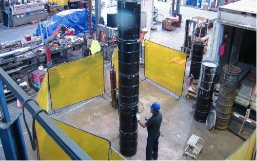
7 It was considered that an appropriately sized spiral welded tube would achieve the required insertion performance, and this type was selected for test. Vibratory Hammer Selection Vibratory hammers contain a system of counter-rotating eccentric weights, powered by hydraulic motors, and designed in such a way that horizontal vibrations cancel out, while vertical vibrations are transmitted into the over-casing, to which the vibratory hammer is fastened by a clamp mechanism. Figure 6 shows a 1219mm (48 inches) over-casing and vibratory hammer at the test facility during pre-testing. Figure 6: Over-casing with vibratory hammer Auger Selection Augers are available for wide variety of applications. The various types and their applications are summarized as follows: Earth auger- These augers are primarily made for digging holes in dirt. They are efficient at penetrating soil, scooping material, and bringing material to the surface. The teeth of the auger are flat and angled horizontal relative to the surface of the ground. This orientation increases its ability to scoop material but greatly restricts it to grinding harder material. Its grinding and penetrating power is weak relative to other augers. 7

8 Figure 7: Earth Auger 8


9 Rock auger- Rock augers are designed for penetration of hard materials and surfaces. Appropriately specified, it optimizes the ability to grind and mix material while penetrating deeper depths. These augers can utilize carbide teeth, which help the augers ability to grind and shred material. Figure 8: Rock Auger Core Barrels- Core barrels are primarily used for grinding and shredding material on the edges of a shaft. It is a hollow bucket that may have teeth or bits on the circumference to enhance grinding. Roller Rock or Tri-cone bits are typical used. Vertical shaft Tri-cone augers - This auger configuration uses a tri-cone bit to grind material at the bit surface. Although it is very effective at shredding rock and concrete it requires either air or water to move material to the surface and away from the bit head. Figure 9: Tri-cone Auger All but the rock augers were considered unsuitable for the VPU size reduction and mixing task, leaving the following characteristic to be considered for rock auger selection. Number of flights- the number of flights can vary from a single flight to a continuous flight auger. The number of flights dictates the mixing power of the auger. The more flights, the better the mixing results due to material being lifted from flight to flight. As a practical matter however, increasing the number of 9
10 flights lengthens the auger, increases the torque required to rotate the auger during grinding and mixing, and increases the probability of damage to the auger. Taper angle- this is the angle of the flights and provides a difference in penetration and ability to grind/mix material at a particular depth. A higher taper angle allows for more/easier penetration. A lower taper provides for better mixing. Type of teeth- Teeth can vary from small to large and the amount of carbide at the tip. Larger teeth may grind and mix better but it is more probable of material getting stuck in the teeth. Position/orientation of flights- flights can be S-shaped, line-shaped, or circular. The distance between flights changes its ability to mix material and put more flights on the auger. The smaller the distances, the more mixing will occur however smaller distances facilitates the ability for material to get stuck in the flights. Thickness of flights- The thicker the flights, the stronger the auger. With thicker flights, more torque and power is necessary to control and lower the auger. Size of Auger- the diameter of the auger influences its ability to mix material and penetrate at different depths. The larger the diameter, the more torque required to penetrate but it greatly increases its ability to mix and grind material with a greater area at different depths. Smaller diameter augers will require less torque to reach deeper depths but will not be sufficient by itself at grinding and mixing a wider area. Cutter head- also known as a stinger, it is an extension that appears on the tip of the auger below the flights. Stingers have different shapes and sizes, depending on the material being augured. Some contain teeth that point in different directions while others are just single cones that protrude at the tip of the auger. Stingers increase the penetration power of augers and help keep the auger centered. Grout Selection The grout mix that was selected for testing comprised: Type I - Ia Portland Cement - ASTM C150 Potable Water Retarder - ASTMC494 Type B Grout Fluidifier - ASTM


11 Waste Removal Equipment Selection The retrieval bucket was selected for pre-testing as the most appropriate method of waste removal. These buckets are shown in figures 10 and 11. Figure 10. Drawing of Retrieval Bucket Figure 11. Retrieval Bucket in use Preparation for Pre-Testing The preparation for Pre-testing comprised the manufacture of surrogate VPUs, and the installation of the surrogate VPUs into the ground on the test site and back-filled with soil which was representative of the soils surrounding the actual VPUs at Hanford. The surrogate VPUs were constructed from 200 liter drums, 5 of which were filled with materials to represent the contents of the Hanford VPUs. Figure 12 shows a selection of contents of the surrogate VPUs, and figure 13 shows the various stages of assembly of the surrogate VPUs. 11


12 Figure 12. Surrogate VPU Contents Figure 13. Assembly of Surrogate VPUs 12


13 Pre-Testing of Installation of the Steel Over-casing around a VPU The pre-testing proved that the steel over-casing could be driven into the simulated Hanford soil to the required depth. Pre-Testing of Penetration, Size Reduction, Stabilization by Mixing A number of sizes of augers and auger types were tested, and it was proved that the surrogate VPUs could be size reduced as required, and that all containers within the VPUs were breached and that the VPU contents and surrounding soils were effectively mixed. Effective mixing will stabilize, in-ground any reactive materials such as un-reacted NaK or super oxides. The size reduced VPU contents were removed from the over-casing for examination. See figure 14. Figure 14. Size Reduced VPU Contents 13


14 Pre-Testing of Grouting It was demonstrated that the selected grout and size reduced VPU contents and soils could be mixed with a rock auger to produce a grouted monolith within the over-casing. Pre-Testing of Removal of Materials Retrieval of size reduced materials was effectively done using a bucket auger and a rock auger. See figure 15. Figure 15. Removal by Rock Auger (Left photo) and by Bucket Auger (Right photo) DESIGN The success of the pre-testing of the selected equipment and subsystems, has provided the base data for the design of the actual equipment to be cold tested then deployed on the Hanford site. This equipment includes the augering and grouting containment systems and retrieval equipment containment systems needed for safe operation with the required radiological controls. This design is currently ongoing. CONCLUSION/IMPORTANCE OF THIS WORK Safe and effective field remediation, removal and disposal of the VPUs in the 600 area are critical to the success of the River Corridor Closure Contract at the U.S. Department of Energy s Hanford Site. 14
15 Safe and effective field remediation, removal and disposal of the VPUs in the 600 area are critical to the success of the River Corridor Closure Contract at the U.S. Department of Energy s Hanford Site. 15
Assalamualaikum & Good Morning (May All Of You Gain A Better Understanding)
") Assalamualaikum & Good Morning (May All Of You Gain A Better Understanding) Always Try To Do The Best In Your Life TYPES OF FOUNDATION TYPES OF FOUNDATION a) Shallow Foundation System i) Spread Foundation
Assalamualaikum & Good Morning (May All Of You Gain A Better Understanding) Always Try To Do The Best In Your Life TYPES OF FOUNDATION TYPES OF FOUNDATION a) Shallow Foundation System i) Spread Foundation
Misan University - College of Engineering Civil Engineering Department
 CHAPTER 2 Soil and Excavations Soil investigation including two phases: surface investigation and subsurface investigation Surface investigation involves making a preliminary judgment about the site s
Lesson 7 REINFORCING CAGE. Version 1-1/
 Lesson 7 REINFORCING CAGE 7-1 Version 1-1/15 7-1 Learning Outcomes Describe cage construction Determine the circumference of a shaft and rebar cage and calculate the required number of side spacers. Explain
ITEM 460 REINFORCED CONCRETE PIPE Description. This Item shall govern for the furnishing of reinforced concrete pipe.
 AFTER MARCH 1, 2012 ITEM 460 REINFORCED CONCRETE PIPE 460.1 Description. This Item shall govern for the furnishing of reinforced concrete pipe. 460.2 Materials. A. Except as modified herein, materials,
CONTINUOUS FLIGHT AUGER (CFA) PILES QC/QA PROCEDURES. Preferred QC/QA Procedures
 PILES QC/QA PROCEDURES. Preferred QC/QA Procedures") Preferred QC/QA Procedures The Federal Highway Administration (FHWA) has provided QC/QA guidance for this technology as noted below. The reference document also contains information about construction
Preferred QC/QA Procedures The Federal Highway Administration (FHWA) has provided QC/QA guidance for this technology as noted below. The reference document also contains information about construction
SPECIFICATIONS - DETAILED PROVISIONS Section Controlled Low Strength Material C O N T E N T S
 SPECIFICATIONS - DETAILED PROVISIONS Section 02253 Controlled Low Strength Material C O N T E N T S PART 1 - GENERAL... 1 1.01 DESCRIPTION... 1 1.02 CLSM MIX DESIGN & EXAMPLE MIX (PER 27 CU. FT. OF MIX)...
SECTION 920 SANITARY AND STORM SEWER MANHOLES
 SECTION 920 SANITARY AND STORM SEWER MANHOLES 920.1 GENERAL This section contains items which are relative to the installation of sanitary and storm sewer manholes. 920.2 REFERENCES 920.2.1 ASTM C 43 C
ITEM 416 DRILLED SHAFT FOUNDATIONS Materials. All materials shall conform to the requirements of the pertinent items as follows:
 ITEM 416 DRILLED SHAFT FOUNDATIONS 416.1. Description. This Item shall govern for the construction of foundations consisting of reinforced concrete drilled shafts and/or nonreinforced concrete drilled
Drilled Shaft. Inspection. HQ Construction Office HQ Geotechnical Division
 Drilled Shaft Inspection HQ Construction Office HQ Geotechnical Division Drilled Shafts: What are Drilled Shafts Drilled Shaft Construction Challenges of Drilled Shaft Construction The WSDOT SHAFT Special
City of Mesquite General Design Standards Revision Date:
 SCREENING WALLS (Public and Private) Page 1 of 6 Section 1 General Design & Notes 1.1 Standards 1.1.1 All screening walls in the City of Mesquite and within its Extraterritorial Jurisdiction (ETJ), both
San Antonio Water System Specifications for Construction ITEM NO. 853 SANITARY SEWER GLASS-FIBER REINFORCED POLYESTER (FRP) MANHOLES
 MANHOLES") ITEM NO. 853 SANITARY SEWER GLASS-FIBER REINFORCED POLYESTER (FRP) MANHOLES 853.1 DESCRIPTION: This item shall govern the construction of FRP sanitary sewer manholes, complete in place and the materials
ITEM NO. 853 SANITARY SEWER GLASS-FIBER REINFORCED POLYESTER (FRP) MANHOLES 853.1 DESCRIPTION: This item shall govern the construction of FRP sanitary sewer manholes, complete in place and the materials
703 - DRILLED SHAFTS SECTION 703 DRILLED SHAFTS
 SECTION 703 DRILLED SHAFTS 703.1 DESCRIPTION Construct drilled shafts by the cased or uncased method depending upon site conditions and Contract Document requirements. BID ITEMS Drilled Shaft (*) (**)
TRENCHLESS CONSTRUCTION (BORING, JACKING, AND TUNNELING)
") PART 1 - GENERAL TRENCHLESS CONSTRUCTION (BORING, JACKING, AND TUNNELING) 1.01 SECTION INCLUDES A. Trenchless Installation of Carrier Pipe with Casing Pipe B. Trenchless Installation of Carrier Pipe without
PART 1 - GENERAL TRENCHLESS CONSTRUCTION (BORING, JACKING, AND TUNNELING) 1.01 SECTION INCLUDES A. Trenchless Installation of Carrier Pipe with Casing Pipe B. Trenchless Installation of Carrier Pipe without
SECTION XXXXX AGGREGATE PIERS PART 1 - GENERAL
 SECTION XXXXX AGGREGATE PIERS PART 1 - GENERAL 1.1 RELATED DOCUMENTS: Drawings and general provisions of the Contract, including General and Supplementary Conditions and other Division 00 and Division
DETENTION, RETENTION AND RECHARGE STRUCTURES
 DETENTION, RETENTION AND RECHARGE STRUCTURES Introduction Foundation, trenchwall, bedding and backfill considerations for multiple barrel detention systems are not unlike those for conventional CSP installations.
STANDARDIZED STRUCTURES
 Q, QH & QL TOWERS 16.1 Q, QH, and QL Towers General Description The series includes three and four leg angle towers, which are suited for a variety of antenna mounting positions and load conditions. The
SECTION 39 - MANHOLES TABLE OF CONTENTS
 Section SECTION 39 - MANHOLES TABLE OF CONTENTS Page 39-1 GENERAL... 39.1 39-2 CONCRETE MANHOLES... 39.1 39-2.01 NOT USED... 39.1 39-2.02 Concrete Storm Drain Manholes... 39.1 39-3 SADDLE SEWER MANHOLES...
North American Society for Trenchless Technology (NASTT) NASTT s 2016 No-Dig Show. Dallas, Texas March 20-24, 2016 WM-T3-01
 NASTT s 2016 No-Dig Show. Dallas, Texas March 20-24, 2016 WM-T3-01") North American Society for Trenchless Technology (NASTT) NASTT s 2016 No-Dig Show Dallas, Texas March 20-24, 2016 WM-T3-01 A Comprehensive Understanding of ASTM F3097-15 Standard Practice for Installation
North American Society for Trenchless Technology (NASTT) NASTT s 2016 No-Dig Show Dallas, Texas March 20-24, 2016 WM-T3-01 A Comprehensive Understanding of ASTM F3097-15 Standard Practice for Installation
MICHIGAN TEST METHOD FOR SAMPLING HMA PAVING MIXTURES BEHIND THE PAVER
 MICHIGAN TEST METHOD FOR SAMPLING HMA PAVING MIXTURES BEHIND THE PAVER 1. Scope 1.1 This method covers the procedures for sampling HMA paving mixtures at the point of delivery immediately behind the paver
KANSAS DEPARTMENT OF TRANSPORTATION SPECIAL PROVISION TO THE STANDARD SPECIFICATIONS, EDITION 2015
 Sheet 1 of 9 KANSAS DEPARTMENT OF TRANSPORTATION SPECIAL PROVISION TO THE STANDARD SPECIFICATIONS, EDITION 2015 Delete SECTION 703 and replace with the following: SECTION 703 DRILLED SHAFTS 703.1 DESCRIPTION
SAMPLE GUIDE SPECIFICATIONS FOR OSTERBERG CELL LOAD TESTING OF DRILLED SHAFTS
 SAMPLE GUIDE SPECIFICATIONS FOR OSTERBERG CELL LOAD TESTING OF DRILLED SHAFTS 1.0 DESCRIPTION This work shall consist of furnishing all materials and labor necessary for conducting an Osterberg Cell (O-cell)
MODEL SPECIFICATIONS: Hydraulically Driven Steel Underpinning Pile Specifications
 MODEL SPECIFICATIONS: Hydraulically Driven Steel Underpinning Pile Specifications Mar/2008 v1.0 SECTION 02255 HYDRAULICLY DRIVEN STEEL UNDERPINNING PILES PART 1 GENERAL 1.01 SCOPE OF WORK The work shall
Bi-Directional Static Load Testing of Drilled Shafts
 Supplemental Technical Specification for Bi-Directional Static Load Testing of Drilled Shafts SCDOT Designation: SC-M-712 (9/15) September 2, 2015 1.0 GENERAL This work shall consist of furnishing all
Bi-Directional Static Load Testing of Drilled Shafts
 Supplemental Technical Specification for Bi-Directional Static Load Testing of Drilled Shafts SCDOT Designation: SC-M-712 (01/18) 1.0 GENERAL This work shall consist of furnishing all materials, equipment,
3. FIELD INVESTIGATION PROGRAM
 Department of Public Works U.S. Army Corps of Engineers Phase 1B Geotechnical Investigation Geotechnical Data Report 3.3 FIELD METHODS AND PROCEDURES 3. FIELD INVESTIGATION PROGRAM The borings were advanced
1 of 1 04/09/ :41
 1 of 1 04/09/2008 06:41 Buried Shipping Containers http://web.archive.org/web/20031124215255/www.cont 1 of 5 04/09/2008 06:41 DO IT YOURSELF...Partial Burial Example FIND A SITE AND EXCAVATE FOR A PARTIAL
SUPPLEMENTAL TECHNICAL SPECIFICATION
 July 14, 2015 HIGH STRAIN DYNAMIC LOAD TESTING OF DRILLED SHAFTS 1.0 GENERAL This work shall consist of performing high-strain dynamic testing using a drop weight loading system on a test drilled shaft
ITEM 461 STRUCTURAL PLATE STRUCTURES. Galvanized steel plates shall conform to AASHTO M167 and aluminum plates shall conform to AASHTO M219.
 ITEM 461 STRUCTURAL PLATE STRUCTURES 461.1. Description. This Item shall govern for the furnishing and installing of structural plate pipes, pipe arches, arches, underpasses, box culverts and special shapes
SECTION STEEL H PILES. A. Section includes steel H piles embedded into drilled concrete piers.
 SECTION 31 62 16 STEEL H PILES PART 1 - GENERAL 1.01 SCOPE OF WORK A. Section includes steel H piles embedded into drilled concrete piers. B. Furnish all labor, materials, equipment and incidentals required
MICHIGAN DEPARTMENT OF TRANSPORTATION SPECIAL PROVISION FOR LOW-TENSION CABLE BARRIER. OPR:CT 1 of 5 APPR:JAR:DBP: FHWA:APPR:
 MICHIGAN DEPARTMENT OF TRANSPORTATION SPECIAL PROVISION FOR LOW-TENSION CABLE BARRIER OPR:CT 1 of 5 APPR:JAR:DBP:09-07-11 FHWA:APPR:09-07-11 a. Description. This work consists of furnishing and installing
Minimum Guidelines for the Design and Use of Underpins When Performing Foundation Stabilization and/or Supplementation UP-08
 Minimum Guidelines for the Design and Use of Underpins When Performing Foundation Stabilization and/or Supplementation UP-08 Table of Contents 1. Title 2. Designation 3. List of Figures 4. Scope 5. Referenced
WM 07 Conference, February 25 March 1, 2007, Tucson, AZ
 Characterization Modeling to Support the Hanford 618-10 and 618-11 Burial Grounds Remediation Design Solution: Two Differing Approaches with Similar Results S.C. Landon North Wind, Inc. 507 Knight St.,
SECTION 39 - MANHOLES TABLE OF CONTENTS 39-1 GENERAL PRECAST CONCRETE MANHOLES
 Section SECTION 39 - MANHOLES TABLE OF CONTENTS 39-1 GENERAL... 39-1 39-2 PRECAST CONCRETE MANHOLES... 39-1 39-2.01 Precast Concrete Storm Drain Manholes... 39-1 39-3 SADDLE MANHOLES... 39-2 39-3.01 Saddle
TRENCHLESS CONSTRUCTION (BORING, JACKING, AND TUNNELING)
") PART 1 - GENERAL TRENCHLESS CONSTRUCTION (BORING, JACKING, AND TUNNELING) 1.01 SECTION INCLUDES A. Trenchless Installation of Carrier Pipe with Casing Pipe B. Trenchless Installation of Carrier Pipe without
PART 1 - GENERAL TRENCHLESS CONSTRUCTION (BORING, JACKING, AND TUNNELING) 1.01 SECTION INCLUDES A. Trenchless Installation of Carrier Pipe with Casing Pipe B. Trenchless Installation of Carrier Pipe without
SECTION / ENGINEERED AGGREGATE PIERS (SOIL REINFORCEMENT AND FOUNDATION SYSTEM)
") PART 1 GENERAL 1.01 WORK INCLUDED SECTION 02360 / 31 34 30.13 ENGINEERED AGGREGATE PIERS (SOIL REINFORCEMENT AND FOUNDATION SYSTEM) A. Provide all equipment, material, labor and supervision to design and
PART 1 GENERAL 1.01 WORK INCLUDED SECTION 02360 / 31 34 30.13 ENGINEERED AGGREGATE PIERS (SOIL REINFORCEMENT AND FOUNDATION SYSTEM) A. Provide all equipment, material, labor and supervision to design and
TERRATORQUE HELICAL ANCHORS AND HELICAL PILING PRODUCT CATALOG
 INTRODUCTION TERRATORQUE HELICAL ANCHORS AND HELICAL PILING PRODUCT CATALOG TerraTorque offers quality helical anchors and helical piling to the construction industry. Our products are available in solid
STANDARD SPECIFICATION FOR CRIBLOCK CONCRETE CRIBWALL
 STANDARD SPECIFICATION FOR CRIBLOCK CONCRETE CRIBWALL 1. SCOPE 2. DESIGN 3. MATERIALS 4. CONSTRUCTION 5. METHOD OF MEASUREMENT AND PAYMENT SCOPE This Specification sets out requirements for the design,
ITEM NN17 - DRILLED SHAFTS ITEM NN17 - DRILLED SHAFTS (LOW OVERHEAD CLEARANCE) ITEM TRIAL SHAFTS
 ITEM TRIAL SHAFTS") DESCRIPTION A. General. This work shall consist of furnishing the materials and installing drilled shafts at the locations, dimensions, and batters shown on the contract plans or where ordered by the Engineer
DESCRIPTION A. General. This work shall consist of furnishing the materials and installing drilled shafts at the locations, dimensions, and batters shown on the contract plans or where ordered by the Engineer
Monitoring Well Construction
 Meeting logistics Monitoring Well Construction Presenter: Art Becker, MGWC, CPG, Past President NGWA President of Drilling and Safety Consultants LLC Please turn off cell phones or switch to vibrate Presentation
Case Study. The Challenge. Deep Micropile Installation Under Existing Multistory Building
 The Challenge The Owners of a former warehouse located in the vibrant tech start-up area south of Market St. in San Francisco made the decision to bring the building up to current earthquake standards
Design Data 4. Jacking Concrete Pipe
 Design Data 4 Jacking Concrete Pipe FOREWORD Jacking or tunneling concrete pipe is an increasingly important construction method for installing concrete pipelines without interrupting commerce, or disturbing
2. PLANNING AND MAKING A SOIL SURVEY
 Sample all soil horizons over 10 cm in thickness; all samples should represent natural soil horizons or 2.0 The purpose of the soil survey 2. PLANNING AND MAKING A SOIL SURVEY The purpose of making a soil
Vertical Extraction Process Implemented at the 118-K-1 Burial Ground for Removal of Irradiated Reactor Debris from Silo Structures 12431
 Vertical Extraction Process Implemented at the 118-K-1 Burial Ground for Removal of Irradiated Reactor Debris from Silo Structures 12431 Douglas B. Teachout*, Clinton J. Adamson**, Ames Zacharias** *Vista
ROTARY DRILLING TECHNIQUES LARGE DIAMETER
 INTRODUCTION This paper presents details about large diameter rotary drilling techniques typically employed in the civil engineering industry. These techniques have also been applied to the resources /
attachment guide Excavators Skid Steer Loaders Multi-Terrain Loaders
 attachment guide Excavators Skid Steer Loaders Multi-Terrain Loaders Attachments available to fit 95% of excavators up to 25 tonne. HAVE USED FOCUS MACHINERY WHEN WE HAVE HAD ALL OUT EQUIPMENT BUSY, SOME
Hydraulic Excavators
 Chapter 8 Hydraulic Excavators Hydraulic excavators are designed to excavate below the ground surface on which the machine rests. These machines have good mobility and are excellent for general-purpose
SECTION XXXXX STONE COLUMNS PART 1 - GENERAL
 SECTION XXXXX STONE COLUMNS PART 1 - GENERAL 1.1 RELATED DOCUMENTS: Drawings and general provisions of the Contract, including General and Supplementary Conditions and other Division 00 and Division 01
CONSTRUCTION SPECIFICATION FOR FOOTINGS AND PADS FOR ELECTRICAL EQUIPMENT
 ONTARIO PROVINCIAL STANDARD SPECIFICATION METRIC OPSS 616 NOVEMBER 2008 CONSTRUCTION SPECIFICATION FOR FOOTINGS AND PADS FOR ELECTRICAL EQUIPMENT TABLE OF CONTENTS 616.01 SCOPE 616.02 REFERENCES 616.03
CTP STITCH-TIE AGAIN! Quick and easy way to re-anchor existing veneers to back-up structures.
 Helical Wall Tie System for Stabilizing Veneers and Structural Repair AGAIN! ANOTHER CTP SOLUTION! CTP STITCH-TIE Quick and easy way to re-anchor existing veneers to back-up structures. Brick to Concrete
1 Revised: 2019 Edition
 STORM SEWERS PART 1 - GENERAL 1.01 SECTION INCLUDES A. Storm Sewers B. Abandonment of Storm Sewers 1.02 DESCRIPTION OF WORK A. Construct storm sewers. B. Abandon storm sewers. 1.03 SUBMITTALS Comply with
U. S. EPA ENVIRONMENTAL RESPONSE TEAM
 STANDARD OPERATING PROEDURES PAGE: 1 of 13 ONTENTS 1.0 SOPE AND APPLIATION 2.0 METHOD SUMMARY 3.0 SAMPLE PRESERVATION, ONTAINERS, HANDLING, AND STORAGE 4.0 POTENTIAL PROBLEMS 5.0 EQUIPMENT 6.0 REAGENTS
Ground Freezing for Tunnel, Shafts, and Adits
 Ground Freezing for Tunnel, Shafts, and Adits Joseph A. Sopko, Adam Curry Moretrench American Corporation Bianca Messina Skanska USA Civil Stephen Njoloma McMillen Jacobs Associates ABSTRACT Construction
Schnabel Foundation Company
 Micropiles for Roadway Support, Bridge Abutments and Metal Signal Poles on US-158 from US-17B to East of Pasquotank River, in Elizabeth City, NC Schnabel Foundation Company Presenter: Stephen Dimino, P.E.
An Introduction to. By Michael L. Schumaker, P.E. An Introduction to Shaner Industries Metal Foundation System
 An Introduction to Metal Foundation System By Michael L. Schumaker, P.E. Introduction Various types of deep foundations are routinely used to support structures. Selection of the appropriate type of deep
Diaphragm wall Construction
 Diaphragm wall Construction Diaphragm wall is a continuous wall constructed in ground in to facilitate certain construction activities, such as: a) As a retaining wall b) As a cut-off provision to support
CONSTRUCTION SPECIFICATION FOR FOOTINGS AND PADS FOR ELECTRICAL EQUIPMENT
 ONTARIO PROVINCIAL STANDARD SPECIFICATION OPSS.MUNI 616 APRIL 2018 CONSTRUCTION SPECIFICATION FOR FOOTINGS AND PADS FOR ELECTRICAL EQUIPMENT TABLE OF CONTENTS 616.01 SCOPE 616.02 REFERENCES 616.03 DEFINITIONS
STANDARD SPECIFICATION Section Auger-Grout Injected Piles Civil Engineering Group Revised: August, 2000
 DIVISION 2: SITE WORK SECTION 02320 AUGER-GROUT INJECTED PILES STANDARD SPECIFICATION PART 1 GENERAL 1.0 DESCRIPTION OF WORK This work shall include all excavation, concrete, equipment and accessories
APPENDIX J PROFICIENCY CHECKLISTS
 APPENDIX J PROFICIENCY CHECKLISTS SPEEDY MOISTURE TEST Equipment Needed: Complete speedy kit, No. 4 sieve, speedy chart, and sample of soil. Make sure moisture tester is clean and in good working order.
TITEN HD Heavy Duty Screw Anchor for Concrete & Masonry
 TITEN HD Heavy Duty Screw Anchor for & Masonry The Titen HD is a patented, high-strength screw anchor for concrete and masonry. The self-undercutting, non-expansion characteristics of the Titen HD makes
Introduction. A publication by Aquamor
 Introduction Very large numbers of family owned wells have been built in Zimbabwe. This number far exceeds 100 000. In almost every case the family itself has excavated the well and in many cases also
MKT VIBRATORY HAMMER SELECTION AND SOILS TRAINING
 MKT VIBRATORY HAMMER SELECTION AND SOILS TRAINING While reviewing this guide if you see this symbol please click to the next slide. Press the F5 key when you are ready to start the slide show. MKT MANUFACTURING,
B R OA DWAY RAC K. High Security
 B R OA DWAY RAC K High Security The Broadway Rack is a great fit on Broadway or in areas where maximum security is a top priority. Made of thick, two-inch square steel, the Broadway Rack renders pipe-cutters
Hydraulic cutting units
 Product range Produced by ATLAS Maschinen GmbH Hydraulic cutting units Hydraulic cutting units SCHAEFF hydraulic cutting units Proven for the toughest day-to-day use If you work with the toughest rock
DEEP DRIVEN GROUND RODS FOR POLES
 Project Procedure DEEP DRIVEN GROUND RODS FOR POLES 07/25/2011 PAGE 1 OF 5 1.0 PURPOSE The purpose of this procedure is to provide guidance for the need for and direction on the installation of deep driven
Progress Energy Southport Nuclear Power Plant Diversion Structure Stabilization Project
 !! Progress Energy Southport Nuclear Power Plant Diversion Structure Stabilization Project Submittal for the Pile Driving Contractors Association (PDCA) 2010 Project of the Year Submitted by:! PROJECT
Remote-Controlled Dismantling of the Thermal Isolation and Preparations for the Primary Shield Removal
 Remote-Controlled Dismantling of the Thermal Isolation and Preparations for the Primary Shield Removal A. Graf, J. Fleisch, S. Neff, WAK GmbH, Eggenstein-Leopoldshafen, Germany S. Klute, E. Koselowski,
ISO INTERNATIONAL STANDARD. Building construction machinery and equipment Terms and definitions
 INTERNATIONAL STANDARD ISO 11375 First edition 1998-04-01 Building construction machinery and equipment Terms and definitions Machines et matériels pour la construction des bâtiments Termes et définitions
Lesson 2 Substructure. Dr S.Sreenath BSc Engg, MSc Engg, MSc (ICM), MBA, PhD
, MBA, PhD") Lesson 2 Substructure Dr S.Sreenath BSc Engg, MSc Engg, MSc (ICM), MBA, PhD Outline Syllabus 1. Demolition 2. Site problems 3. Substructure 4. Basements 5. Structural Frames 6. Floors 7. External walls
Lesson 2 Substructure Dr S.Sreenath BSc Engg, MSc Engg, MSc (ICM), MBA, PhD Outline Syllabus 1. Demolition 2. Site problems 3. Substructure 4. Basements 5. Structural Frames 6. Floors 7. External walls
SPECIFICATIONS - DETAILED PROVISIONS Section Progressing Cavity Pump C O N T E N T S
 SPECIFICATIONS - DETAILED PROVISIONS Section 11938 - Progressing Cavity Pump C O N T E N T S PART 1 - GENERAL... 1 1.01 GENERAL... 1 1.02 RELATED SPECIFICATION SECTIONS... 1 1.03 MANUFACTURERS... 1 PART
PIANC UK Seminar Design Developments and Specification for Steel. Duncan Nicholson Arup Fellow 9/3/17 ICE London
 PIANC UK Seminar Design Developments and Specification for Steel Duncan Nicholson Arup Fellow 9/3/17 ICE London Contents 1. Design Issues 2. SPERWall Edition 3 (2016) 1. Steel Sheet Piles (Section 14)
STANDARD SPECIFICATION FOR MICROPILE CONSTRUCTION
 Section 67.0 Knoxville, Tennessee March 2013 1. Description STANDARD SPECIFICATION FOR MICROPILE CONSTRUCTION a) This work shall consist of constructing micropiles as shown on the Contract plans in accordance
MANHOLES, VAULTS AND CATCH BASINS SECTION A. Section Soil and Aggregate Materials. C. Section Storm Drainage Systems
 SECTION 02607-1 1.0 GENERAL 1.1 SCOPE: A. This section covers the work necessary for the construction of sanitary and storm system manholes, catch basins, and miscellaneous concrete structures complete.
SPECIFICATION FOR REINFORCED SOIL WALL
 SPECIFICATION FOR REINFORCED SOIL WALL 1.0 EXTENT OF WORK The work shall consist of Reinforced Soil walls built in accordance with this specification and in conformity with the lines, levels and details
Plug Welding Procedures
 Plug Welding Procedures When removing or replacing plates bonded by spot welding, drill through the spot weld nugget and remove. The combinations shown in the figures below apply when plates are to be
SPECIAL SPECIFICATION 4492 Tie Back Anchors
 2004 Specifications CSJ 0504-02-022 SPECI SPECIFICATION 4492 Tie Back Anchors 1. Description. This Item shall govern for the installation of tie-back anchors in place, with grouting as required in accordance
SECTION 44 SHOTCRETE, CAST CONCRETE CHANNEL LINING, AND GROUTED COBBLE TABLE OF CONTENTS
 SECTION 44 SHOTCRETE, CAST CONCRETE CHANNEL LINING, AND GROUTED COBBLE TABLE OF CONTENTS Section Page 44-1 SHOTCRETE... 44.1 44-1.01 Description... 44.1 44-1.02 Materials... 44.1 44-1.03 Proportions...
Drilling bit classification
 Drilling Bits Drilling bit classification 1.Roller Cone Bit Milled Tooth Bit Inserted Tooth Bit 2. Fixed Cutter Bit (Drag Bit) Roller Cone Bit Roller cone bits are comprised of two or three cones having
SPECIFICATION : BORING AND JACKING
 SPECIFICATION 330524: BORING AND JACKING PART 1.0 GENERAL 1.1 DESCRIPTION 1.1.1 The work of this specification includes all labor, machinery, construction equipment and appliances required to perform in
Multi-Institutional Academic Health Science & Research Center Evansville, IN
 SECTION 02370 AUGER CAST PILES PART 1 - GENERAL 1.1 SECTION INCLUDES: The work covered by these specifications consists of furnishing all labor, equipment and materials for the installation of auger cast
4.16. APPLICATION INSTRUCTIONS Construction Joints & Details
 APPLICATION INSTRUCTIONS Construction Joints & Details 4.16 Krystol Waterstop System DESCRIPTION The Krystol Waterstop System is used to permanently waterproof concrete construction joints. It is installed
SECTION PRECAST CONCRETE MANHOLES
 SECTION 02601 PRECAST CONCRETE MANHOLES PART 1 GENERAL 1.1 The work specified in this section shall include the furnishing, hauling, and placing of all precast manholes shown on the drawings and as specified
Decommissioning of Dairyland Power s Lacrosse Boiling Water Reactor
 Decommissioning of Dairyland Power s Lacrosse Boiling Water Reactor Dairyland Power Cooperative The plant achieved initial criticality in July, 1967. Full power was reached in August, 1969 and was declared
Ohio Department of Transportation Division of Production Management Office of Geotechnical Engineering. Geotechnical Bulletin
 Ohio Department of Transportation Division of Production Management Office of Geotechnical Engineering Geotechnical Bulletin GB 2 SPECIAL BENCHING AND SIDEHILL EMBANKMENT FILLS Geotechnical Bulletin GB2
Concrete Prestressed Concrete Pretensioned Concrete Posttensioned Concrete Typical Tendon Layout
 Concrete 45 1.13.0 Prestressed Concrete Concrete in which internal stresses (forces) are induced by means of prestressing steel tendons such that tensile stresses resulting from loads are counteracted
STANDARD SPECIFICATIONS SECTION BORING AND JACKING. A. Section includes requirements for boring and jacking casing pipe.
 STANDARD SPECIFICATIONS SECTION 02445 BORING AND JACKING PART 1 GENERAL 1.1 DESCRIPTION A. Section includes requirements for boring and jacking casing pipe. 1.2 DEFINITIONS A. Carrier Pipe: Sewer or water
Hilti, Inc South 122 nd East Avenue Tulsa, OK
 ttached are page(s) from the 2011 Hilti North merican Product Tech Guide. For complete details on this product, including data development, product specifications, general suitability, installation, corrosion,
SECTION HANGERS AND SUPPORTS FOR PLUMBING PIPING AND EQUIPMENT
 SECTION 220529 HANGERS AND SUPPORTS FOR PLUMBING PIPING AND EQUIPMENT PART 1 - GENERAL 1.1 RELATED DOCUMENTS A. Drawings and general provisions of the Contract, including General and Supplementary Conditions
SECTION PIPE INSTALLATION
 SECTION 02232 PIPE INSTALLATION A. General The pipe shall be Ductile Iron pipe with Tyton push-on joints and cement lined as described and manufactured in accordance with ANSI/AWWA C151/A21.51. Gaskets
Soil Improvement by Compaction Grouting
 CITY AND COUNTY OF DENVER ENGINEERING DIVISION Wastewater Capital Projects Management Standard Construction Specification 31-3223.12 Soil Improvement by Compaction Grouting Part 1 - General 1.01 Introduction
San Antonio Water System Standard Specifications for Construction ITEM NO. 853 SANITARY SEWER GLASS-FIBER REINFORCED POLYESTER (FRP) MANHOLES
 MANHOLES") ITEM NO. 853 SANITARY SEWER GLASS-FIBER REINFORCED POLYESTER (FRP) MANHOLES 853.1 DESCRIPTION: This item shall govern the construction of FRP sanitary sewer complete in place and the material therein,
ITEM NO. 853 SANITARY SEWER GLASS-FIBER REINFORCED POLYESTER (FRP) MANHOLES 853.1 DESCRIPTION: This item shall govern the construction of FRP sanitary sewer complete in place and the material therein,
Paragraph Description Page No General Materials Concrete Masonry Work Altitude Valve Vault Cover 25-4
 City of Columbia Engineering Regulations PART 25: SPECIFICATIONS FOR ALTITUDE VALVE VAULT Table of Contents Paragraph Description Page No. 25.1 General 25-1 25.2 Materials 25-1 25.3 Concrete Masonry Work
1. METALS 2. FERRIC METALS 3. NON-FERRIC METALS 4. WORKING WITH METALS 5. METAL FORMING TECHNIQUES 6. ENVIRONMENTAL IMPACT OF METAL EXTRACTION
 METALS: 1. METALS 2. FERRIC METALS 3. NON-FERRIC METALS 4. WORKING WITH METALS 5. METAL FORMING TECHNIQUES 6. ENVIRONMENTAL IMPACT OF METAL EXTRACTION 1. METALS: Metals are chemical elements found in nature
Page 7-1 Hubbell Power Systems, Inc. All Rights Reserved Copyright 2014 DRAWINGS & RATINGS
 Page 7-1 Hubbell Power Systems, Inc. All Rights Reserved Copyright 2014 PRODUCT DRAWINGS AND RATINGS Section 7 CONTENTS ATLAS RESISTANCE PIERS... 7-3 PIER PIPE SHAFTS... 7-3 REMEDIAL REPAIR BRACKETS for
ITEM 431 PNEUMATICALLY PLACED CONCRETE. All material shall conform to the pertinent requirements of the following items:
 ITEM 431 PNEUMATICALLY PLACED CONCRETE 431.1. Description. This Item shall govern for furnishing and placing of "Pneumatically Placed Concrete" for encasement of designated structural steel members, the
Lesson 4. Construction Techniques and Materials. Learning Outcomes. Basic Construction
 Lesson 4 Construction Techniques and Materials schnabel-eng.com Learning Outcomes Describe sequence of construction for a micropile Identify materials used to construct a micropile Describe principle function
Lantz-Boggio Architects, P.C LBA Project No
 SECTION 313430- PART 1 GENERAL 1.1 WORK INCLUDED A. Provide all equipment, material, labor and supervision to design and install Engineered Aggregate Piers for the soil reinforcement. Design shall rely
DIVISION 2 - SITE WORK
 Montgomery County Public Schools Facilities Guide DIVISION 2 - SITE WORK Conditions of Use/ Responsibility of Data These guideline specifications are to be used by the A/E as a base document in the development
mtec REPORT OF GEOTECHNICAL EXPLORATION FTFA Construct Bin Wall at HERD Eglin AFB, Florida
 mtec REPORT OF GEOTECHNICAL EXPLORATION FTFA 14-3001 - Construct Bin Wall at HERD Eglin AFB, Florida MTEC Project Number 2014-101 November 10, 2014 Revised: January 5, 2015 Prepared For: Peterson Engineering,
Construction Planning, Equipment, and Methods PILES AND PILE-DRIVING EQUIPMENT
 CHAPTER Construction Planning, Equipment, and Methods PILES AND PILE-DRIVING EQUIPMENT Sixth Edition A. J. Clark School of Engineering Department of Civil and Environmental Engineering 19 By Dr. Ibrahim
SECTION MANHOLES AND STRUCTURES. A. Section Includes: 1. Manholes for water, storm drain and sanitary sewer systems.
 SECTION 33 05 13 MANHOLES AND STRUCTURES PART 1 GENERAL 1.1 SUMMARY A. Section Includes: 1. Manholes for water, storm drain and sanitary sewer systems. B. Related Sections: 1. Section 03 20 00 - Concrete