New Hanover County Schools Testing Department Upgrades TABLE OF CONTENTS. Division Section Title Pages PROCUREMENT AND CONTRACTING DOCUMENTS GROUP
|
|
|
- Gwen Harris
- 5 years ago
- Views:
Transcription
1
2
3 Testing Department Upgrades TABLE OF CONTENTS Division Section Title Pages PROCUREMENT AND CONTRACTING DOCUMENTS GROUP DIVISION 00 - PROCUREMENT AND CONTRACTING REQUIREMENTS Invitation to Bid... 1 Section I Information for Bidders Section II Single Prime Bid Form Section III $100K to Under $300K - Owner-Contractor Agreement and Bonds... 9 Section IV Minority Business Participation... 1 Section V General Conditions Section VI Miscellaneous Forms... 4 SPECIFICATIONS GROUP General Requirements Subgroup DIVISION 01 - GENERAL REQUIREMENTS Summary Allowances Alternates Payment Procedures Submittal Procedures References Temporary Facilities and Controls Execution Requirements Cutting and Patching Closeout Procedures... 4 DIVISION 02 - EXISTING CONDITIONS Facility Construction Subgroup Selective Demolition Asbestos Abatement DIVISION 04 - MASONRY Unit Masonry Assemblies TABLE OF CONTENTS Testing Department Upgrades TOC - 1
4 Testing Department Upgrades TABLE OF CONTENTS Division Section Title Pages DIVISION 06 WOOD, PLASTICS & COMPOSITES Miscellaneous Rough Carpentry... 7 DIVISION 07 - THERMAL AND MOISTURE PROTECTION Fluid-Applied Membrane Air and Water Barriers Thermoplastic Single-Ply Roofing Sheet Metal Flashing and Trim (Aluminum) Roof Accessories Joint Sealants... 4 DIVISION 08 - OPENINGS Hollow Metal Doors and Frames Aluminum-Framed Entrances and Storefronts Door Hardware Glass and Glazing... 7 DIVISION 9 FINISHES Painting... 7 DIVISION 23 HVAC Mechanical General Mechanical Existing Conditions Mechanical Demolition Identification for HVAC Piping and Equipment Testing, Adjusting, and Balancing for HVAC Duct Insulation Metal Ducts Air Duct Accessories Packaged, Small-Capacity, Rooftop Air-Conditioning Units... 3 TABLE OF CONTENTS Testing Department Upgrades TOC - 2
5 Testing Department Upgrades TABLE OF CONTENTS Division Section Title Pages DIVISION 26 ELECTRICAL Electrical General Electrical Selective Electrical Demolition Building Wire and Cable Grounding and Bonding Supporting Devices Raceways and Boxes for Electrical Systems Electrical Identification Fuses Enclosed Switches... 3 END TABLE OF CONTENTS TABLE OF CONTENTS Testing Department Upgrades TOC - 3
6
7 INVITATION TO BID invites general contractors to bid on construction of Testing Department Upgrades Project Number: Sealed bids will be received by the Office of Facility Planning & Construction in the New Hanover County Administration Building, Facility Planning Conference Room, 6410 Carolina Beach Road Wilmington, North Carolina 28412, on Tuesday, July 24, All bids will be opened and read aloud starting at 11:00 a.m. This project will be bid and awarded in accordance with G.S , Informal Bidding Procedures. The project consists of, but is not limited to, roof replacement, and exterior door and window replacement on a two-story masonry building with a footprint of 2,196 square feet. There is also mechanical and electrical work associated with removing and reinstalling roof top mechanical units. Licensed General Contractors must have a minimum of five (5) years of experience on competitively bid publicly funded construction projects e.g. City, County, State or School Systems. A mandatory Pre-Bid Conference will be held on Tuesday, July 10, 2018, at 10:00 a.m. at The Testing Department, 1807 South 13 th Street, Wilmington, NC The Design Consultant and a representative from New Hanover County Schools will be available at that time to answer questions concerning the project. Questions after that time shall be submitted in writing to the Design Consultant at Bowman Murray Hemingway Architects, Attn: Daniel Hill, AIA, 514 Market Street, Wilmington, North Carolina or to Leanne Lawrence, Director of Facility Planning & Construction,, 6410 Carolina Beach Road Wilmington, North Carolina Complete plans and specifications may be obtained from Bowman Murray Hemingway Architects, 514 Market Street, Wilmington, NC by calling during normal office hours beginning Thursday, July 5, A refundable plan deposit in the amount of $200 is required. Partial sets will not be available. Plan deposits shall be made payable to and mailed to Bowman Murray Hemingway Architects, attention Catherine Beaman. The deposit will be refunded upon return of the Contract Documents in good condition within thirty (30) days. Contract documents are also available for review at Office of Facility Planning and Construction. Electronic copies are available at no cost and may be requested by ing beaman@bmharch.com. A Bid Security in the amount of five percent (5%) of the Base Bid Amount must accompany each Bid in accordance with Section I - Information for Bidders of the project specifications. No Bid may be withdrawn for a period of forty-five (45) days after the opening thereof. The successful Bidder will be required to furnish a 100% Performance Bond and a 100% Labor and Material Payment Bond. has a verifiable ten percent (10%) goal for participation by minority businesses in the total value of the work. Bidders are required on school construction and renovation projects to make a good faith effort to meet this goal. Bidders shall identify on its bid the minority businesses that it will use on the project. Bidders shall submit along with the bid an affidavit listing the good faith efforts it has made pursuant to Section I Information for Bidders, Article I-8, Minority Participation, and the total dollar value of the bid that will be performed by the minority businesses. A bidder that performs all of the work under the contract with its own workforce may submit an affidavit to that effect in lieu of the aforementioned affidavit otherwise required under this subsection. reserves the right to reject any and all bids, waive informalities and irregularities in bidding, and to accept bids which are considered to be in the best interest of the School System. Dated for Publication: July 5, 2018
8
9 SECTION I INFORMATION FOR BIDDERS I-1. SUBMISSION OF BIDS AND BID OPENING: A. Bids will be received by Facility Planning and Construction Department and will be opened and read at the time(s) and place(s) set forth in the Invitation to Bid. Bidders, or their representative, and other interested persons may be present at the opening of the Bids. B. The envelope containing the Bid must be sealed and addressed to New Hanover County Schools, Facility Planning and Construction Department, Administration Building, 6410 Carolina Beach Road Wilmington, NC The outside of the envelope should also indicate the the name of the Project, the name of the Bidder and the Bidder s North Carolina State Contractor's License Number. C. The Bidder shall assume full responsibility for timely delivery at the location designated for receipt of Bids. [When the Owner solicits both multiple prime and single prime Bids, the Owner shall establish separate deadlines for the submission of Bids.] The time with respect to the Bid will be the Eastern Standard, or Daylight Savings, Time for the United States as maintained by the Time Services Department of the U.S. Naval Observatory: Bids will not be accepted after the time(s) set forth in the Invitation to Bid. D. Bids will be received in accordance with the Invitation to Bid. I-2. BIDDING DOCUMENTS: A. Bidding Documents include the Invitation to Bid, Information for Bidders, Bid Form, Bid Security, Affidavits of Minority Business Participation, and the Contract Documents, including any Addenda issued prior to receipt of Bids. All requirements and obligations of the Bidding Documents are hereby incorporated by reference into the Contract Documents and are binding on the successful Bidder upon award of the Contract. B. Bidders may obtain complete sets of the Bidding Documents as designated in the Invitation to Bid in the number, and for the deposit, if any, stated therein. C. Bidders shall use complete sets of Bidding Documents in preparing Bids; neither the Owner nor the Design Consultant shall assume any responsibility for errors or misinterpretations resulting from the use of incomplete sets of Bidding Documents. D. The Owner in making copies of the Bidding Documents available on the above terms does so only for the purpose of obtaining Bids on the Work and does not confer a license or grant for any other use. NHCS Formal Contract Documents Section I - Information for Bidders (March 2018) I - 1
10 I-3. DEFINITIONS: A. BID: A Bid is a complete and properly signed proposal to do the Work, or designated portion thereof, for the sums stipulated therein, submitted in accordance with the Bidding Documents and G. S and B. BASE BID: The Base Bid is the sum stated in the Bid for which the Bidder offers to perform the Work described in the Bidding Documents as the base, to which work may be added, or from which work may be deleted, for sums stated in Alternate Bids, if any. B. ALTERNATES: An Alternate Bid (or Alternate) is an amount stated in the Bid to be added to or deducted from the amount of the Base Bid if the corresponding change in the Work, as described in the Bidding Documents, is accepted. D. HE/HIS: The term He or His is not intended to be gender specific. I-4. I-5. QUALIFICATION OF BIDDER: NOT REQUIRED BIDDER'S REPRESENTATIONS: Each Bidder by submitting his Bid represents that: A. He has read and understands the Bidding Documents and his Bid is made in accordance therewith; and Bidder agrees to be bound by the terms and requirements set forth in the Bidding Documents. B. He has visited the site, has familiarized himself with the local conditions under which the Work is to be performed in accordance with Article I-9 herein, and has correlated his observations with the requirements of the Bidding Documents. C. His Bid is based upon the materials, systems and equipment required by the Bidding Documents without exception. D. He has the capability, in all respects, and the moral and business integrity, reliability, technical ability, financial resources, plant, management, superintendents, equipment and materials which will assure effective and efficient good faith performance in full compliance with the Bidding Documents, and with any and all schedules and completion dates required by the Owner. The Bidder acknowledges and represents in his estimating, planning and scheduling of the Work that the Contract Time has made allowances for normal inclement weather indigenous to the Project site. The Bidder hereby certifies that the Work shall be completed, in place, in full accordance with the Bidding Documents, within the time limits specified. E. He agrees that upon receipt of the Notice of Award, he will execute the formal Contract, and will deliver all bonds and proof of insurance coverage as required by the Bidding Documents. F. He agrees to execute the formal Contract within ten (10) buisness days from the date of Notice of Award, and in case he fails or neglects to appear within the specified time to execute the Contract, he will be considered as having abandoned the Contract, and the Bid NHCS Formal Contract Documents Section I - Information for Bidders (March 2018) I - 2
11 Security accompanying his Bid will be forfeited to the Owner by reason of such failure on the part of the Bidder. G. He has made a good faith effort to meet New Hanover County School s verifiable ten percent (10%) goal for participation by minority businesses in the total value of the Work. The Bidder shall identify on the Bid Form the minority businesses that will be used on the Project. The Bidder shall submit along with the Bid, Affidavit A - Listing of Good Faith Efforts pursuant to subsection (f) of G.S and the total dollar value of the Bid that will be performed by the minority businesses. A Bidder that performs one hundred percent (100%) of the Work under the Contract with its own workforce must submit Affidavit B - Intent to Perform Contract with Own Forces in lieu of the aforementioned affidavit otherwise required under this subsection. H. He has reviewed the General and Supplemetal Conditions included in the Bidding Documents. I-6. BID SECURITY: A. Each Bid must be accompanied by (1) cash; or (2) a Cashier's Check or a Certified Check of the Bidder in an amount not less than five percent (5%) of the Base Bid amount, made payable to the Owner; or (3) a Bidder's bond on the Bid Bond Form provided herein or on a similar form which in every respect materially complies with said Bid Bond Form, in the amount of five percent (5%) of his Bid. For purposes of this provision, the amount of the Bid shall be the Base Bid. The Bidder's bond shall be issued by a Surety company licensed to conduct business in North Carolina and acceptable to the Owner. B. Said Bid Security is given as a guarantee that the Bidder will enter into a Contract if awarded the Work and, in the case of refusal or failure to so enter into said Contract, the Bid Security shall be declared forfeited to the Owner. Such Bid Security shall be returned to all but the three lowest Bidders within three (3) days after the opening of Bids and the remaining Bid Securities will be returned within forty eight (48) hours after the Owner and the successful Bidder have executed the Contract. If no Contract has been awarded or the Bidder has not been notified of the acceptance of his Bid within forty-five (45) days of the Bid opening, the Bidder may withdraw his Bid and request the return of his Bid Security. If, at the Owner's request, the Bidder agrees to extend and maintain his Bid beyond the specified forty-five (45) days, his Bid Security will not be returned until the expiration of the period of extension. I-7. FORFEITURE OF BID BOND: The successful Bidder, upon his failure or refusal to execute the Contract within ten (10) business days after he has received Notice of Award, shall forfeit to the Owner the Bid Security deposited with his Bid in accordance with North Carolina General Statute I-8. MINORITY BUSINESS ENTERPRISES It is the policy of the Owner to encourage the use of minority businesses in all school construction contracts and have a verifiable percentage goal of ten percent (10%) participation in the total value of the Work. It is the intent of this policy that the Owner, as the awarding authority for school construction projects, and the Contractors and Subcontractors performing the Work shall cooperate and in good faith do all things legal, proper, and reasonable to achieve the verifiable goal of ten NHCS Formal Contract Documents Section I - Information for Bidders (March 2018) I - 3
12 percent (10%) participation. Each Bidder will take specific actions to insure a good faith effort in the recruitment and selection of minority businesses including but not limited to: SUBMITTED WITH BID: A. For Bids that will include subcontracts: The Bidders must earn at least fifty (50) points from the good faith efforts listed below, and submit with their Bid an affidavit identifying which efforts were utilized. This affidavit is Affidavit A Listing of Good Faith Efforts and is included as an attachment to Section II Single Prime Bid Form. 1. (10 pts) Contact minority businesses that reasonably could have been expected to submit a quote and that are known to the Bidder, or available on State or local government maintained lists, at least ten (10) days before the Bid date and notify them of the nature and scope of the work to be performed. 2. (10 pts) Make the Bidding Documents and other requirements available for review by prospective minority businesses, or provide these documents to them at least ten (10) days before the Bids are due. 3. (15 pts) Break down or combine elements of the Work into economically feasible units to facilitate minority participation. 4. (10 pts) Work with minority trade, community, or contractor organizations identified by the Office of Historically Underutilized Businesses that provide assistance in recruitment of minority businesses. 5. (10 pts) Attend Prebid meetings scheduled by the public owner. 6. (20 pts) Provide assistance in getting required bonding or insurance or provide alternatives to bonding or insurance for Subcontractors. 7. (15 pts) Negotiate in good faith with interested minority businesses and do not reject them as unqualified without sound reasons based on their capabilities. Any rejection of a minority business based on lack of qualification should have the reasons documented in writing. 8. (25 pts) Provide assistance to an otherwise qualified minority business in need of equipment, loan capital, lines of credit, or joint pay agreements to secure loans, supplies, or letters of credit, including waiving credit that is ordinarily required. Assist minority businesses in obtaining the same unit pricing with the Bidder's suppliers in order to help minority businesses in establishing credit. 9. (20 pts) Negotiate joint venture and partnership arrangements with minority businesses in order to increase opportunities for minority business participation on a public construction or repair project when possible. 10. (20 pts) Provide quick pay agreements and policies to enable minority contractors and suppliers to meet cash-flow demands. NHCS Formal Contract Documents Section I - Information for Bidders (March 2018) I - 4
13 B. For Bids that include work performed with its own workforce: A Bidder that performs all of the Work under the Contract with its own workforce may submit with their Bid an affidavit to that effect in lieu of the affidavit mentioned in the previous Subsection A. This affidavit is Affidavit B Intent to Perform Contract with Own Forces and is included as an attachment to Section II Single Prime Bid Form. NOTE: The Bidder must include either Affidavit A Listing of Good Faith Efforts or Affidavit B Intent to Perform Contract with Own Forces with its Bid. Failure to include either of these affidavits with the Bid may result in declaring the Bid non-responsive. C. Each Bidder shall identify on its Bid the minority businesses that it will use on the Project and the corresponding dollar value of the minority business s bid. Section II Single Prime Bid Form provides space for the Bidder to enter this information. SUBMITTED BY THE LOWEST RESPONSIBLE, RESPONSIVE BIDDER WITHIN 72 HOURS AFTER NOTIFICATION OF BEING LOW BIDDER A. An affidavit that includes a description of the portion of the Work to be executed by the minority businesses, expressed as a percentage of the Base Bid, which is equal to or greater than the verifiable ten percent (10%) goal. This affidavit is Affidavit C Portion of the Work to be Performed by Minority Firms and is included as an attachment to Section II Single Prime Bid Form. B. Documentation of its good faith effort to meet the verifiable ten percent (10%) goal. The documentation must include evidence of all good faith efforts that were implemented, including any advertisements, solicitations, and evidence of other specific actions demonstrating recruitment and selection of minority businesses for participation in the Contract. This affidavit is Affidavit D Good Faith Efforts and is included as an attachment to Section II Single Prime Bid Form. NOTE: The lowest Responsible and Responsive Bidder must submit either Affidavit C Portion of the Work to be Performed by Minority Firms or Affidavit D Good Faith Efforts within 72 hours after notification of being low Bidder. Failure to submit either of these affidavits within the time provided may result in declaring the Bid non-responsive. I-9. SITE CONDITIONS AND CONDITIONS OF THE WORK: A. Each Bidder must acquaint himself thoroughly as to the character and nature of the Work to be done. Each Bidder furthermore must make a careful examination of the site of the Work and inform himself fully as to the difficulties to be encountered in the performance of the Work, the facilities for delivering, storing and placing materials and equipment, and other conditions relating to construction and labor. B. No plea of ignorance of conditions that exist or may hereafter exist on the site of the Work, or difficulties that may be encountered in the execution of the Work, as a result of failure to make necessary investigations and examinations, will be accepted as an excuse for any failure or omission on the part of the successful Bidder to fulfill in every detail all the requirements of the Contract Documents and to complete the Work or the consideration set forth therein, or as a basis for any claim whatsoever. NHCS Formal Contract Documents Section I - Information for Bidders (March 2018) I - 5
14 C. Insofar as possible, the successful Bidder, in carrying out his work, must employ such methods or means as will not cause interruption of or interference with the Work of the Owner or any Separate Contractor. I-10. BIDDER'S QUESTIONS, ADDENDA AND INTERPRETATIONS: A. Bidders shall promptly notify the Design Consultant of any ambiguity, inconsistency or error which they may discover upon examination of the Bidding Documents or of the site and local conditions. No interpretation of the meaning of the Drawings, Specifications or other Bidding Documents will be made to any Bidder orally. B. Every request for such interpretation should be in writing addressed to the Design Consultant with a copy forwarded to the Owner. C. Any and all such interpretations and any supplemental instructions will be in the form of written addenda to the Bidding Documents which, if issued, will be transmitted to all prospective Bidders (at the respective addresses furnished for such purposes) not later than three (3) calendar days prior to the date fixed for the opening of Bids. Neither the Design Consultant nor the Owner will be responsible for any other explanations or interpretations of the Bidding Documents. Failure of any Bidder to receive any such addenda or interpretation shall not relieve any Bidder from any obligation under his Bid as submitted. All addenda so issued shall become part of the Contract Documents. D. Each Bidder shall ascertain prior to submitting his Bid that he has received all addenda issued, and he shall acknowledge receipt and inclusion in his Bid of all addenda. F. The Design Consultant and a representative from will be available at a Pre-Bid Conference to answer questions concerning the Project. The date and time of the Pre-Bid Conference shall be determined in the Invitation to Bid. Questions after that time shall be submitted in writing to the Design Consultant or to Leanne Lawrence, AIA, Director of Facility Planning and Construction,, 6410 Carolina Beach Road, Wilmington, NC I-11. SECURITY FOR FAITHFUL PERFORMANCE: The successful Bidder shall furnish a Performance Bond in an amount equal to one hundred percent (100%) of the Contract Sum as security for the faithful performance of this Contract and also a Labor and Material Payment Bond in an amount not less than one hundred percent (100%) of the Contract Sum, as security for the payment of all persons performing labor and furnishing materials under this Contract. The successful Bidder shall provide a Performance Bond and a Labor and Material Payment Bond, in accordance with State law and shall be delivered to the Owner not later than the date of execution of the Contract by the successful Bidder. I-12. TIME OR COMPLETION AND LIQUIDATED DAMAGES FOR NON-COMPLETION: The time for completion of this Contract and Liquidated Damages for non-completion within the stipulated time shall be as fixed in the Owner-Contractor Agreement, the General Conditions and the Supplemental Conditions. I-13. LOCATION OF WORK: NHCS Formal Contract Documents Section I - Information for Bidders (March 2018) I - 6
15 The site of the Work is on Owner owned property, public streets, easements and/or other right-ofways, as shown on the Bidding Documents. I-14. LIABILITY INSURANCE AND WORKMEN'S COMPENSATION: The successful Bidder will be required to maintain Commercial General Liability, Workmen's Compensation and other insurance in the amounts and under the terms stipulated in the General Conditions and Supplemental Conditions. I-15. BIDDERS REFERRED TO LAWS: A. The attention of Bidders is called to the provisions of all Federal, State, County and Municipal laws, regulations, ordinances, resolutions, and permits relating to obstructing streets, maintaining signals, storing and handling of explosives, affecting the Bidder, or his employees or his work hereunder in his relation to the Owner or any other person or entity. The Bidder shall obey all such laws, regulations, ordinances, permits or resolutions controlling or limiting Contractors while engaged in the execution of the Work under the Contract. B. The provisions of the Contract shall be interpreted in accordance with the laws of North Carolina and in accordance with the laws, ordinances, regulations, permits and resolutions of local Municipalities and New Hanover County. I-16. TAXES All applicable Federal, State and Local Taxes shall be included in the Bid. The successful Bidder shall provide the Owner with documentation of North Carolina sales taxes paid for all purchases on the Project in a form provided by the Owner and included as attachment Appendix A in Section V- General Conditions of the Owner-Contractor Agreement for Construction. I- 17. RIGHT TO REJECT BIDS: The Owner expressly reserves the right to reject any or all Bids, to waive any informalities or irregularities in the Bids received, and to accept that Bid which in its judgment, best serves the interest of the Owner. I-18. EQUAL PRODUCTS AND SUBSTITUTIONS: A. Whenever possible, the Design Consultant shall specify in the Bidding Documents, the required performance and design characteristics for materials as required by N.C. Gen. Stat When it is impossible or impractical to specify the required performance and design characteristics for materials, the Design Consultant may use a certain brand, make, manufacturer, article, device, product, material, fixture, form or type construction by name, make or catalog number to convey the general style, type, character and standard of quality of the article desired. Unless specifically stated to the contrary, any Bidder may, submit a request to use an article, device, product, material, fixture, form or type of construction which will be evaluated by the Design Consultant with respect to quality, workmanship, economy of operation, durability, suitably for the purpose intended, and acceptability for use on the Project. Such requests must be submitted ten (10) days prior to the Bid opening date. NHCS Formal Contract Documents Section I - Information for Bidders (March 2018) I - 7
16 Approval by the Owner prior to Bid opening will be in the form of an Addendum to the Bidding Documents issued to all prospective Bidders indicating that the additional makes or brands appear to be equivalent to those specified. Nothing in this Paragraph is intended to restrict or inhibit free and open competition on school system projects. B. The Bidder may request approval for substitutions after award of the Contract in accordance with the provisions of Article 4.15 of the General Conditions. I-19. PREPARATION AND SUBMITTAL OF BID: A. Bids shall be submitted utilizing the Bid Form as bound herein as Section II, or otherwise provided with the Bidding Documents, and shall be complete in every respect. The Base Bid amount shall be entered in words and figures in the space provided. Where applicable, the unit price or lump sum items, and their extensions, shall be entered in figures in the respective columns provided for each Bid item. All entries shall be typewritten or printed in ink. The signatures of all persons shall be in longhand. Any entry of amount that appears on the face of the Bid to have involved an erasure, deletion, white-out and/or substitution or other such change or alteration, shall show by them the initials of the person signing the Bid and the date of the change or alteration. A failure to comply with this requirement may be cause for disqualification of the Bid. B. For unit price bids, in the event of any discrepancies between the unit prices and the extensions thereof or the Base Bid amount, the unit prices shall govern. For lump sum bids, in the event of a discrepancy between the Base Bid amount in writing and that in figures, the written value shall govern. C. Bids shall not contain any restatement or qualifications of work to be done, and alternate bids will not be considered unless called for. No oral Bids or modifications will be considered. D. The amount of a Bid submitted by a Subcontractor to the Bidder under the single prime contracting system shall not exceed the Bid, if any, for the same work by that Subcontractor to the Owner under the multiple prime system. E. Each single prime Bid shall identify the major Subcontractors, including but not limited to the Subcontractors selected to perform the mechanical, electrical and plumbing portions of the Work, and the Subcontractors respective bid prices for the work. I-20. MODIFICATION OR WITHDRAWAL OF BID: A. A Bidder may withdraw his Bid from consideration if such Bid was based upon a mistake as provided in North Carolina General Statute B. Prior to the time and date designated for receipt of Bids, any Bid submitted may be modified or withdrawn by notice to the party receiving Bids at the place designated for receipt of Bids. Such Notice shall be in writing over the signature of the Bidder and submitted before the date and time set for receipt of Bids, and it shall be so worded as not to reveal the amount of the original Bid. NHCS Formal Contract Documents Section I - Information for Bidders (March 2018) I - 8
17 C. Withdrawn Bids may be resubmitted up to the time designated for the receipt of Bids provided that they are then fully in conformance with this Section I - Information for Bidders. D. Bid Security, if any is required, shall be in an amount sufficient for the Bid as modified or resubmitted. I- 21. DETAILED BID BREAKDOWN: If the Owner directs, the Bidder shall provide a detailed breakdown of his Bid acceptable to the Owner. In addition to verifying accounting requirements, the breakdown may be used by the Owner to determine whether the Bidder has grossly misjudged the requirements of any area. Failure to provide the requested detailed breakdown may result in rejection of the Bid. I- 22. AWARD OF CONTRACT: The Contract will be awarded to the lowest Responsive and Responsible Bidder under the single prime system [or to the lowest responsive and responsible bidders under the multiple prime system] taking into consideration quality, performance, and the time specified in the Bids for the performance of the Contract. A. The lowest multiple prime Bidders and the lowest single prime Bidder shall be determined by the aggregate amount of the unit prices set forth in the Bid Form, if work is bid on a unit price basis, or the aggregate amount of the Base Bid, plus any Alternates selected by the Owner. Both multiple prime and single prime Bids will be received and awarded according to State law. B. A Responsive Bidder shall mean a Bidder who has submitted a Bid which conforms, in all material respects, to the Bidding Documents. C. A Responsible Bidder shall mean a Bidder who has the capability, in all respects, to perform fully the Contract requirements and the moral and business integrity and reliability which will assure good faith performance. In determining responsibility, the following criteria will be considered: 1. The ability, capacity and skill of the Bidder to perform the Contract or provide the service required; 2. Whether the Bidder can perform the Contract or provide the service promptly, or within the time specified, without delay or interference; 3. The character, integrity, reputation, judgment, experience and efficiency of the Bidder; 4. The quality of performance of previous contracts or services. For example the following information will be considered: NHCS Formal Contract Documents Section I - Information for Bidders (March 2018) I - 9
18 a. The administrative and consultant cost overruns incurred by Owners on previous contracts with the Bidder, b. The Bidder's compliance record with General Conditions on other projects, c. The submittal by the Bidder of excessive and/or unsubstantiated extra cost proposals and claims on other projects, d. The Bidder's record for completion of the Work within the Contract Time and Bidder s compliance with scheduling and coordination requirements on other projects, e. The Bidder's demonstrated cooperation with the Owner or the Design Consultant and other contractors on previous contracts, f. Whether the work performed and materials furnished on previous contracts was in accordance with the Contract Documents; 5. The previous and existing compliance by the Bidder with laws and ordinances relating to contracts or services; 6. The sufficiency of the financial resources and ability of the Bidder to perform the Work under the Contract or provide the service; 7. The quality, availability and adaptability of the goods or services to the particular use required; 8. The ability of the Bidder to provide future maintenance and service for the warranty period of the Contract; 9. Whether the Bidder is in arrears to the Owner on debt or contract or is a defaulter on surety to the Owner; 10. Whether the Bidder has demonstrated a good faith effort to use minority businesses as Subcontractors; 11. Such other information as may be secured by the Owner having a bearing on the decision to award the Contract, to include, but not limited to: a. The ability, experience and commitment of the Bidder to properly and reasonably plan, schedule, coordinate and execute the Work, b. Whether the Bidder has ever been debarred from bidding or found ineligible for bidding on any other projects. D. The purpose of the above is to enable the Owner in its opinion, to select the lowest Responsible Bidder. The ability of the low Bidder to provide the required bonds will not of itself demonstrate responsibility of the Bidder. E. The Owner reserves the right to require from the Bidder: (1) submissions of references, within seven (7) days of Bid opening, to include a listing of previous and current projects and NHCS Formal Contract Documents Section I - Information for Bidders (March 2018) I - 10
19 (2) financial statements indicating current financial status, prepared in accordance with generally accepted accounting principles, by a CPA licensed to do business in North Carolina, (3) AIA Document A305 Contractor s Qualification Statement and (4) any other information deemed necessary in order to establish the Responsiveness and Responsibility of the Bidder. F. The Owner reserves the right to defer award of the Contract for a period of forty-five (45) days after the opening of Bids. During this period of time, the Bidder shall guarantee the prices quoted in his Bid. END OF INFORMATION FOR BIDDERS NHCS Formal Contract Documents Section I - Information for Bidders (March 2018) I - 11
20
21 SECTION II SINGLE PRIME BID FORM FOR: TO: Testing Department Upgrades Project number: Contract number: Facility Planning and Construction Department Administration Building 6410 Carolina Beach Road Wilmington, North Carolina FROM: BIDDER ADDRESS CITY STATE ZIP PHONE FAX ADDRESS 1. BASE BID PROPOSAL: Having become completely familiar with the local conditions affecting the cost of the Work at the place where the Work is to be executed, and having carefully examined the site conditions as they currently exist, and having carefully examined the Bidding Documents prepared by Bowman Murray Hemingway Architects and titled: Testing Department Upgradees Dated May. 2018, together with any addenda to such Bidding Documents as listed hereinafter, the undersigned hereby proposes and agrees to provide all labor, materials, plant, equipment, transportation and other facilities as necessary and/or required to execute all of the Work described by the aforesaid Bidding Documents for the lump sum consideration of: (Bidder shall write in the amount of the Base Bid here) Dollars ($ ) said amount being hereinafter referred to as the Base Bid or Base Bid Proposal. 2. BID BREAKDOWN: NOT REQUIRED NHCS Formal Contract Documents Section II Single Prime Bid Form (March 2018) II - 1
22
23 3. SUBCONTRACTOR LISTING Bidders shall identify below the names of major Subcontractors, including but not limited to Subcontractors selected to perform the mechanical, electrical and plumbing portions of the Work, and the Subcontractors respective bid prices for the work. This information is required to be submitted at bid time. Failure to include this information shall be cause for disqualification or rejection the Bid. (Bidder shall write in the names and amounts of subcontracts below) Name of Subcontractor Amount of Bid 4. ALTERNATES: ALTERNATE NO. 1: Preferred Brand Alternate State the amount to be added to the base bid to provide the basis of design door hardware as specified in section No substitutions permitted. Adjust Base Bid by [ADDING or DELETING] ALTERNATE NO. 2: Dollars ($ ) State the amount to be added to the base bid to provide and install the rooftop safety rails as delineated on drawing sheets A1.0 and A3.0. Adjust Base Bid by [ADDING or DELETING] Dollars ($ ) 5. UNIT PRICES AND ALLOWANCES Base Bid includes all cash allowances listed below. Unused amount will be credited to the Owner by Change Order at the end of the Project. Allowance #1: Unforeseen Conditions $5,000 NHCS Formal Contract Documents Section II Single Prime Bid Form (March 2018) II - 2
24
25 Unit prices are complete for labor, equipment, material and overhead and profit; Base Bid includes all quantity allowances listed below. Unused amount will be credited to the Owner by Change Order at the end of the Project. (Bidder shall write in the unit prices for description of work listed below) N/A 6. MINORITY BUSINESSES: Please circle the Ownership category of your firm: Non-Minority (NM) / Black, African American (B) / Hispanic (H) / Asian-American (A) / American Indian (I) / White Female (F) / Socially & Economically Disadvantaged (D). If Ownership is Minority Female (circle): NO Firm is not minority owned. YES Firm is minority-female owned. Source of Ownership category (certification/ verification) (circle one): Not Applicable / State of NC HUB / State of NC DOT / Local Agency / Federal Agency / Out-of State Agency / Self-Identified / Unknown Each Bidder shall identify on its Bid the minority businesses that it will use on the project and the corresponding total dollar value of the minority business s bid. (Bidder shall write in the names and subcontract amount of minority businesses used in bid) Name of Minority Business Subcontract Amount Total Dollar Value of the Bid to be Performed by Minority Contractors $ NHCS Formal Contract Documents Section II Single Prime Bid Form (March 2018) II - 3
26
27 In addition to the information above, the Bidder must complete and provide with the Bid one of the following affidavits: Affidavit A Listing of Good Faith Efforts This affidavit documents the good faith efforts of the Bidder and is to be submitted with the Bid if the Bidder is subcontracting portions of the Work. Affidavit B Intent to Perform Contract with Own Forces This affidavit documents the intent of the Bidder to perform the Contract with its own workforce and is to be submitted with the Bid if the Bidder is not subcontracting portions of the Work. NOTE: The Bidder must submit with the Bid either Affidavit A or Affidavit B. Failure to include either one of these affidavits will result in declaring the Bid non-responsive. 7. ADDENDA ACKNOWLEDGEMENT: The undersigned acknowledges receipt of the following addenda: (Bidder to write in the number and date appearing on each addendum received) Addendum No. Date Addendum No. Date 8. BID SECURITY: Bid security in the amount of five (5) percent of the Base Bid is attached, without endorsement, in the sum of Dollars ($ ) which is to become the property of the Owner in the event the Contract and Performance and Payment Bonds are not executed within the time set forth, as Liquidated Damages for the delay and additional work caused the Owner. 9. The undersigned declares that the person or persons signing this Bid is/are fully authorized to sign on behalf of the firm listed and to fully bind the firm listed to all the Bid conditions and provisions thereof. 10. It is agreed that no person, persons or company, other than the firm listed below or as otherwise indicated, has any interest whatsoever in this Bid or the Contract that may be entered into as a result of the Bid, and that in all respects the Bid is legal and firm, and submitted in good faith without collusion or fraud. 11. It is agreed that the undersigned has complied, or will comply, with all requirements of all Federal, State, and local laws, and that no legal requirement has been, or will be, violated in making or accepting this Bid, in awarding the Contract, and/or in the prosecution of the Work required. 12. It is agreed that the undersigned shall provide any information deemed necessary by the Owner to establish the responsiveness and responsibility of the Bidder. NHCS Formal Contract Documents Section II Single Prime Bid Form (March 2018) II - 4
28
29 13. The undersigned acknowledges that he has received copies of all the Bidding and Contract Documents for the Project. 14. The following information is provided pursuant to the Contract Documents: 1. Legal Name of Firm: a. If Firm is a corporation; state that corporation is organized under the laws of the State of Please affix corporate seal to this Form of Bid. b. If Firm is a partnership, state names of partners: c. If Firm is an individual using a trade name, state name of individual: 2. North Carolina Contractor s License Number: Respectfully submitted, this day of, 20 (Signature) (Name Typed) (Title) (SEAL IF BIDDER IS A CORPORATION) END OF SINGLE PRIME BID FORM Enclosures: 1. Bid Bond 2. Either Affidavit A Listing of Good Faith Efforts or Affidavit B Intent to Perform Contract with Own Forces NHCS Formal Contract Documents Section II Single Prime Bid Form (March 2018) II - 5
30
31 BID BOND KNOW ALL MEN BY THESE PRESENTS, That we, (Bidder's Name) (Street Address) hereinafter called the Principal, and, of (City, State, Zip) (Surety's Name) a corporation organized and existing under the Laws of the State of, and authorized to transact business in the State of, as Surety, hereinafter called Surety, are held and firmly bound unto as the Owner and hereinafter called Obligee, in the Penal sum of five percent (5%) of the amount bid, good and lawful money of the United States of America, for the payment of which the Principal and Surety bind themselves, their heirs, executors, administrators, successors and assigns, jointly and severally, firmly by these presents. The Condition of this Obligation is such, that, WHEREAS the Principal has submitted a Bid to the Obligee a Contract for the construction of (Contract Name and Number) NOW THEREFORE, if the Obligee shall accept the Bid of the Principal and the Principal shall enter into a Contract with the Obligee in accordance with the terms of such Bid, and give such bond or bonds as may be specified in the Bidding or Contract Documents with good and sufficient surety for the faithful performance of such construction for the prompt payment of labor and material furnished in the prosecution thereof, or in the event of the failure of the Principal to enter such Contract and give such bond or bonds, if the Principal shall pay to the Obligee the difference not to exceed the penalty hereof between the amount specified in said Bid and such larger amount for which the Obligee may in good faith contract with another party to perform the Work covered by said Bid, then this obligation shall be null and void; otherwise to remain in full force and effect. In witness whereof, we have hereunto set our signatures and seal this day of, 19, all pursuant to due authorization. NHCS Formal Contract Documents Section II Single Prime Bid Form (March 2018) II - 6
32
33 Principal / Owner (Seal) By Surety By Attorney-in-Fact in accordance with the attached Power of Attorney STATE OF ) COUNTY OF ) ) ss: I,, a Notary Public in and for the State and County aforesaid, do hereby certify that, and, whose names are signed to the foregoing bond, this day personally appeared before me in my State and County aforesaid and acknowledged the same. Given under my hand seal this day of, 19. Notary Public (Seal) My Commission expires: NHCS Formal Contract Documents Section II Single Prime Bid Form (March 2018) II - 7
34
35 AFFIDAVIT A LISTING OF GOOD FAITH EFFORTS County of Affidavit of (Name of Bidder) I have made a good faith effort to comply under the following areas checked: Bidders must earn at least 50 points from the good faith efforts listed for their bid to be considered responsive. q 1 (10 pts) Contacted minority businesses that reasonably could have been expected to submit a quote and that were known to the contractor, or available on State or local government maintained lists, at least 10 days before the bid date and notified them of the nature and scope of the work to be performed. q 2 -- (10 pts) Made the construction plans, specifications and requirements available for review by prospective minority businesses, or providing these documents to them at least 10 days before the bids are due. q 3 (15 pts) Broken down or combined elements of the Work into economically feasible units to facilitate minority participation. q 4 (10 pts) Worked with minority trade, community, or contractor organizations identified by the Office of Historically Underutilized Businesses and included in the Bid documents that provide assistance in recruitment of minority businesses. q 5 (10 pts) Attended prebid meetings scheduled by the public owner. q 6 (20 pts) Provided assistance in getting required bonding or insurance or provided alternatives to bonding or insurance for Subcontractors. q 7 (15 pts) Negotiated in good faith with interested minority businesses and did not reject them as unqualified without sound reasons based on their capabilities. Any rejection of a minority business based on lack of qualification should have the reasons documented in writing. q 8 (25 pts) Provided assistance to an otherwise qualified minority business in need of equipment, loan capital, lines of credit, or joint pay agreements to secure loans, supplies, or letters of credit, including waiving credit that is ordinarily required. Assisted minority businesses in obtaining the same unit pricing with the Bidder's suppliers in order to help minority businesses in establishing credit. q 9 (20 pts) Negotiated joint venture and partnership arrangements with minority businesses in order to increase opportunities for minority business participation on a public construction or repair project when possible. q 10 - (20 pts) Provided quick pay agreements and policies to enable minority contractors and suppliers to meet cash-flow demands. NHCS Formal Contract Documents Section II Single Prime Bid Form (March 2018) II - 8
36
37 The undersigned, if apparent low Bidder, will enter into a formal agreement with the firms listed in the Identification of Minority Business Participation schedule conditional upon scope of the Contract to be executed with the Owner. Substitution of contractors must be in accordance with GS (d). Failure to abide by this statutory provision will constitute a breach of the Contract. The undersigned hereby certifies that he or she has read the terms of the minority business commitment and is authorized to bind the Bidder to the commitment herein set forth. Date: Name of Authorized Officer: Signature: Title: State of North Carolina, County of SEAL Subscribed and sworn to before me this day of 20 Notary Public My commission expires NHCS Formal Contract Documents Section II Single Prime Bid Form (March 2018) II - 9
38
39 AFFIDAVIT B INTENT TO PERFORM CONTRACT WITH OWN FORCES County of Affidavit of (Name of Bidder) I hereby certify that it is our intent to perform 100% of the Work required for the (Name of Project) contract. In making this certification, the Bidder states that the Bidder does not customarily subcontract elements of this type project, and normally performs and has the capability to perform and will perform all elements of the work on this project with his/her own current work forces; and The Bidder agrees to provide any additional information or documentation requested by the Owner in support of the above statement. The undersigned hereby certifies that he or she has read this certification and is authorized to bind the Bidder to the commitments herein contained. Date: Name of Authorized Officer: Signature: SEAL Title: State of North Carolina, County of Subscribed and sworn to before me this day of 20 Notary Public My commission expires NHCS Formal Contract Documents Section II Single Prime Bid Form (March 2018) II - 10
40
41 AFFIDAVIT C Portion of the Work to be Performed by Minority Firms County of (Note: this form is to be submitted ONLY by the apparent lowest responsible, responsive bidder. This form is not to be included with bid.) If the portion of the work to be executed by minority businesses as defined in GS (g) is equal to or greater than 10% of the bidders total contract price, then the Bidder must complete this affidavit. Either Affidavit C or Affidavit D shall be provided by the apparent lowest responsible, responsive Bidder within 72 hours after notification of being low Bidder. Affidavit of on the (Name of Bidder) (Project Name) I do hereby certify that Project ID# Amount of Bid $ I will expend a minimum of % of the total dollar amount of the contract with minority business enterprises. Minority businesses will be employed as construction subcontractors, vendors, suppliers or providers of professional services. Such work will be subcontracted to the following firms listed below. Attach additional sheets if required. Name and Phone Number *Minority Category Work description Dollar Value *Minority categories: Black, African American (B), Hispanic (H), Asian American (A), American Indian (I),Female (F) Socially and Economically Disadvantaged (D) NHCS Formal Contract Documents Section II Single Prime Bid Form (March 2018) II - 11
42
43 Pursuant to GS (d), the undersigned will enter into a formal agreement with Minority Firms for work listed in this schedule conditional upon execution of a contract with the Owner. Failure to fulfill this commitment may constitute a breach of the contract. The undersigned hereby certifies that he or she has read the terms of this commitment and is authorized to bind the bidder to the commitment herein set forth. Date: Name of Authorized Officer: Signature: Title: State of North Carolina, County of SEAL Subscribed and sworn to before me this day of 20 Notary Public My commission expires NHCS Formal Contract Documents Section II Single Prime Bid Form (March 2018) II - 12
44
45 AFFIDAVIT D Good Faith Efforts County of (Note: this form is to be submitted ONLY by the apparent lowest responsible, responsive bidder. This form is not to be included with bid.) If the goal of 10% participation by minority business is not achieved, the Bidder must complete this affidavit. Either Affidavit C or Affidavit D shall be provided by the apparent lowest responsible, responsive Bidder within 72 hours after notification of being low Bidder. Affidavit of: (Name of Bidder) I do certify the attached documentation as true and accurate representation of my good faith efforts. Attach additional sheets if required Name and Phone Number Minority Category Work description Dollar Value *Minority categories: Black, African American (B), Hispanic (H), Asian American (A) American Indian (I), Female (F), Socially and Economically Disadvantaged (D) Documentation of the Bidder's good faith efforts to meet the goals set forth in these provisions. Examples of documentation include, but are not limited to, the following evidence: A. Copies of solicitations for quotes to at least three (3) minority business firms from the source list provided by the State for each subcontract to be let under this contract (if 3 or more firms are shown on the source list). Each solicitation shall contain a specific description of the work to be subcontracted, location where bid documents can be reviewed, representative of the Prime Bidder to contact, and location, date and time when quotes must be received. B. Copies of quotes or responses received from each firm responding to the solicitation. C. A telephone log of follow-up calls to each firm sent a solicitation. D. For subcontracts where a minority business firm is not considered the lowest responsible sub-bidder, copies of quotes received from all firms submitting quotes for that particular subcontract. E. Documentation of any contacts or correspondence to minority business, community, or contractor organizations in an attempt to meet the goal. F. Copy of pre-bid roster. G. Letter documenting efforts to provide assistance in obtaining required bonding or insurance for minority business. H. Letter detailing reasons for rejection of minority business due to lack of qualification. NHCS Formal Contract Documents Section II Single Prime Bid Form (March 2018) II - 13
46
47 I. Letter documenting proposed assistance offered to minority business in need of equipment, loan capital, lines of credit, or joint pay agreements to secure loans, supplies, or letter of credit, including waiving credit that is ordinarily required. Failure to provide the documentation as listed in these provisions may result in rejection of the bid and award to the next lowest responsible and responsive bidder. Date: Name of Authorized Officer: Signature: Title: State of North Carolina, County of SEAL Subscribed and sworn to before me this day of 20 Notary Public My commission expires NHCS Formal Contract Documents Section II Single Prime Bid Form (March 2018) II - 14
48
49 SECTION III OWNER-CONTRACTOR AGREEMENT PROJECT NAME: Testing Department Upgrades NHCS PROJECT NUMBER: THIS AGREEMENT, in three (3) copies, made this [ date ] day of [ month ] by and between the New Hanover County Board of Education (herein referred to as the "Owner"), whose mailing address is, Facility Planning and Construction Department, 6410 Carolina Beach Road, Wilmington, North Carolina and [ contractor name ] (herein referred to as the "Contractor"), whose mailing address is [ contractor address ]. Correspondence, submittals, and notices relating to or required under this Contract shall be sent in writing to the above addresses; unless either party is notified in writing by the other, of a change in address. WITNESSETH: WHEREAS, it is the intent of the Owner to obtain the services of the Contractor in connection with the construction of Repairs to: NHCS Testing Department Upgrades hereinafter referred to as the "Project" or the "Work"; and WHEREAS, the Contractor desires to perform such construction in accordance with the terms and conditions of this Agreement, NOW, THEREFORE, in consideration of the promises made herein and other good and valuable consideration, the following terms and conditions are hereby mutually agreed to, by and between the Owner and Contractor: Article 1 DEFINITIONS 1.1 All terms in this Agreement which are defined in Section I- Information for Bidders and Section V- General Conditions of the Owner-Contractor Agreement shall have the meanings designated therein. 1.2 The Contract Documents are as defined in Section V- General Conditions of the Owner- Contractor Agreement. Such documents form the Contract, and all are as fully a part thereof as if attached to this Agreement or repeated herein. Article 2 STATEMENT OF THE WORK 2.1 The Contractor shall provide and pay for all materials, tools, equipment, labor and professional and non-professional services, and shall perform all other acts and supply all other things NHCS Informal Contract Documents Section III - Owner-Contractor Agreement (March 2018) III -1
50 necessary, to fully and properly perform and complete the Work, as required by the Contract Documents. 2.2 The Contractor shall further provide and pay for all related facilities described in any of the Contract Documents, including all work expressly specified therein and such additional work as may be reasonably inferred therefrom, saving and excepting only such items of the Work as are specifically stated in the Contract Documents not to be the obligation of the Contractor. The totality of the obligations imposed upon the Contractor by this Article and by all other provisions of the Contract Documents, as well as the structures to be built and the labor to be performed, is herein referred to as the "Work". Article 3 DESIGN CONSULTANT 3.1 The Design Consultant shall be Bowman Murray Hemingway Architects whose address is 514 Market Street, Wilmington, NC 82401; however, that the Owner may, without liability to the Contractor, unilaterally amend this Article from time to time by designating a different person or organization to act as its Design Consultant and so advising the Contractor in writing, at which time the person or organization so designated shall be the Design Consultant for purposes of this Contract. Article 4 TIME OF COMMENCEMENT AND COMPLETION 4.1 The Contractor shall commence the Work promptly upon the date established in the Notice to Proceed. If there is no Notice to Proceed, the date of commencement of the Work shall be the date of this Agreement or such other date as may be established herein. 4.2 Time is of the essence with respect to the Contractor s obligations. The Contractor shall achieve Final Completion on or before the date established for Final Completion. 4.3 Dates listed in this Article shall be adhered to unless modified in writing by mutual agreement between the Contractor and the Owner. All dates indicate midnight unless otherwise stipulated. The only exceptions to this schedule are defined in Section V- General Conditions of the Owner- Contractor Agreement for Construction under Paragraph 7.2 DELAYS AND EXTENSIONS OF TIME. The first floor of the Testing Department Building will remain occupied and in use until November 1. The building will not be occupied from November 2 through November 29. All scope of work on the first floor must be completed between November 2 and November 29 including work related to doors, windows, HVAC, and electrical. Notice of Award: July 25, 2018 Notice to Proceed: Contract Activities August 1, 2018 Substantial Completion Roofing: October 22, 2018 Notice to Proceed: Construction Activities, 1 st Floor November 2, 2018 Substantial Completion: November 29, 2018 Final Completion: December 7, 2018 NHCS Informal Contract Documents Section III - Owner-Contractor Agreement (March 2018) III -2
51 The Owner reserves the right to withhold the issuance of Notice to Proceed by up to thirty (30) days. For each day that Notice to Proceed is withheld pursuant to this paragraph, the dates established for Substantial Completion and Final Completion shall be adjusted. The Contractor shall not be entitled to additional compensation if the Owner withholds the issuance of Notice to Proceed pursuant to this paragraph. 4.4 This paragraph will define the normal scheduled working hours for the Work. If the normal scheduled working hours are not defined, the contractor shall have access to the Work at all times. Normal Scheduled Working Hours: [time of day from and until] 4.5 If the Contractor should fail to complete the Work on or before the dates stipulated for Substantial Completion and/or Final Completion, or such later date as may result from an extension of time granted by the Owner, he shall pay the Owner, as Liquidated Damages, the sums set forth in Section V- General Conditions of the Owner-Contractor Agreement for Construction under Paragraph 8.9 LIQUIDATED DAMAGES. Article 5 CONTRACT SUM 5.1 Provided that the Contractor shall strictly and completely perform all of its obligations under the Contract Documents, and subject only to additions and deductions by Modification or as otherwise provided in the Contract Documents, the Owner shall pay to the Contractor, in current funds and at the time and in the installments hereinafter specified, the sum of [ contract amount in words ] Dollars [$ numerical contract amount ] herein referred to as the "Contract Sum". 5.2 The Contract Sum includes the following unit prices and allowances: Allowance No. 1: Unforeseen Conditions: $5, Allowance No. 2: [ description and amount ] Allowance No. 3: [ description and amount ] Allowance No. 4: [ description and amount ] Allowance No. 5: [ description and amount ] Allowance No. 6: [ description and amount ] Unit Price for [ description and amount ] Unit Price for [ description and amount ] Unit Price for [ description and amount ] Unit Price for [ description and amount ] Unit Price for [ description and amount ] Unit Price for [ description and amount ] Article 6 PROGRESS PAYMENTS 6.1 The Contractor hereby agrees that, on or about the twenty-third day of the month for every month during the performance of the Work, he will deliver to the Design Consultant an Application for Payment in accordance with the provisions of Article 8 of Section V- General Conditions of the NHCS Informal Contract Documents Section III - Owner-Contractor Agreement (March 2018) III -3
52 Owner-Contractor Agreement for Construction. This date may be changed upon mutual agreement, stated in writing, between the Owner and Contractor. Payment under this Contract shall be made as provided in Section V- General Conditions of the Owner-Contractor Agreement for Construction. Article 7 OTHER REQUIREMENTS 7.1 The Contractor shall submit the Performance Bond, Labor and Material Payment Bond and Certificates of Insurance as required by the Contract Documents. 7.2 The Owner shall furnish to the Contractor three set(s) of drawings and three set(s) of the project manual, at no extra cost, for use in the construction of the Work. The Contractor may obtain additional sets by paying the Owner for the costs of reproduction, handling and mailing. 7.3 The Contractor will make a good faith effort to utilize Minority Businesses per North Carolina G.S (c) and G.S (f) as Subcontractors in the performance of the Contract. NHCS Informal Contract Documents Section III - Owner-Contractor Agreement (March 2018) III -4
53 IN WITNESS WHEREOF, New Hanover County Board of Education (hereinbefore called the Owner ) has caused these presents to be signed and attested by its Superintendent and Assistant Superintendent for Planning and Operations, and (contractor name) (hereinbefore called Contractor ) has caused these presents to be signed by its President and its Corporate seal to be hereunto affixed, as hereinafter attested. NEW HANOVER COUNTY BOARD OF EDUCATION Dr. Tim Markley Superintendent Date Eddie Anderson Date Assistant Superintendent for Planning and Operations This instrument has been preaudited in the manner required by the School Budget and Fiscal Control Act. Mary Hazel M. Small Chief Financial Officer Date [CONTRACTOR COMPANY NAME] Signature Date Printed Name and Title Attest: Date Printed Name (Seal) NHCS Informal Contract Documents Section III - Owner-Contractor Agreement (March 2018) III -5
54
55 Bond Forms PERFORMANCE BOND IT IS HEREBY AGREED that Contractor) (Insert full name and address of as Principal, hereinafter called Contractor, and, (Insert full name and address of Surety) as Surety, hereinafter called Surety, are held and firmly bound unto the New Hanover County Board of Education 6410 Carolina Beach Road, Wilmingotn NC as Obligee, hereinafter called Owner, in the amount of Dollars ($ ), for the payment whereof Contractor and Surety bind themselves, their heirs, executors, administrators, successors and assigns, jointly and severally, firmly by these obligations. WHEREAS, Contractor has by written agreement dated, 20, entered into a contract with Owner for the construction of (Insert the name of the Project) in accordance with Drawings and Specifications prepared by Architect/Engineer) (Insert full name and address of which contract is by reference made a part hereof, and is hereinafter referred to as the Contract. NOW, THEREFORE, THE CONDITION OF THIS OBLIGATION is such that, if Contractor shall promptly and faithfully perform said Contract, then this obligation shall be null and void; otherwise it shall remain in full force and effect. The Surety hereby waives notice of any alteration or extension of time made by the Owner. Whenever Contractor shall be, and declared by Owner to be in default, under the Contract, the Owner having performed Owner s obligations thereunder, the Surety may promptly remedy the default, or shall promptly: 1) Complete the Contract in accordance with its terms and conditions, or 2) Obtain a bid or bids for completing the Contract in accordance with its terms and conditions, and upon determination by Surety of the lowest responsible bidder, or, if the Owner elects, upon determination by the Owner and the Surety jointly of the lowest responsible bidder, arrange for a contract between such bidder and Owner, and make available as Work progresses NHCS Informal Contract Documents Section III - Owner-Contractor Agreement (March 2018) III -6
56
57 (even though there should be a default or a succession of defaults under the contract or contracts of completion arranged under this paragraph) sufficient funds to pay the cost of completion less the balance of the contract price; but not exceeding, including other costs and damages for which the Surety may be liable hereunder, the amount set forth in the first paragraph hereof. The term balance of the contract price, as used in this paragraph, shall mean the total amount payable by Owner to Contractor under the Contract and any amendments thereto, less the amount properly paid by Owner to Contractor. Any suit under this bond must be instituted before the expiration of any applicable statute of limitations under the Contract. No right of action shall accrue on this bond to or for the use of any person or corporation other than the Owner named herein or the heirs, executors, administrators or successors of the Owner. Signed and sealed this day of 20. PRINCIPAL [Affix corporate seal] (Name) (Title) (Witness) SURETY [Affix corporate seal] (Name) (Title) (Witness) NHCS Informal Contract Documents Section III - Owner-Contractor Agreement (March 2018) III -7
58
59 LABOR AND MATERIAL PAYMENT BOND THIS BOND IS ISSUED SIMULTANEOUSLY WITH PERFORMANCE BOND IN FAVOR OF THE OWNER CONDITIONED ON THE FULL AND FAITHFUL PERFORMANCE OF THE CONTRACT IT IS HEREBY AGREED that (Insert full name and address of Contractor) as Principal, hereinafter called Principal, and, (Insert full name and address of Surety) as Surety, hereinafter called Surety, are held and firmly bound unto the New Hanover County Board of Education 6410 Carolina Beach Road, Wilmington NC as Obligee, hereinafter called Owner, for the use and benefit of claimants as herein below defined, in the amount of Dollars ($ ), for the payment whereof Principal and Surety bind themselves, their heirs, executors, administrators, successors and assigns, jointly and severally, firmly by these obligations. WHEREAS, Principal has by written agreement dated, 20, entered into a contract with Owner for the construction of (Insert the name of the Project) in accordance with Drawings and Specifications prepared by Architect/Engineer) (Insert full name and address of which contract is by reference made a part hereof, and is hereinafter referred to as the Contract. NOW, THEREFORE, THE CONDITION OF THIS OBLIGATION is such that, if Principal shall promptly make payment to all claimants as hereinafter defined, for all labor and material used or reasonably required for use in the performance of the Contract, then this obligation shall be void; otherwise it shall remain in full force and effect, subject, however, to the following conditions: 1. A claimant is defined as one having a direct contract with the principal or with a Subcontractor of the Principal for labor, material, or both, used or reasonably required for use in the performance of the Contract, labor and material being construed to include that part of water, gas, power, light, heat, oil, gasoline, telephone service or rental of equipment directly applicable to the Contract. 2. The above named Principal and Surety hereby jointly and severally agree with the Owner that every claimant as herein defined, who has not been paid in full before the expiration of a period of ninety (90) days after the date on which the last of such claimant s work or labor was done or performed, or materials were furnished by such claimant, may sue on this bond for the use of such claimant, prosecute the NHCS Informal Contract Documents Section III - Owner-Contractor Agreement (March 2018) III -8
60
61 suit to final judgment for such sum or sums as may be justly due claimant, and have execution thereon. The Owner shall not be liable for the payment of any costs or expenses of any such suit. 3. No suit or action shall be commenced hereunder by any claimant: a) Unless claimant, other than one having a direct contract with the Principal, shall have given written notice to any two of the following: the Principal, the Owner, or the Surety above named, within ninety (90) days, after such claimant did or performed the last of the work or labor, or furnished the last of the materials for which said claim is made, stating with substantial accuracy the amount claimed and the name of the party to whom the materials were furnished, or for whom the work or labor was done or performed. Such notice shall be served by mailing the same by registered mail or certified mail; postage prepaid, in an envelope addressed to the Principal, Owner or Surety, at any place where an office is regularly maintained for the transaction of business, or served in any manner in which legal process may be served in the state in which the aforesaid project is located, save that such service need not be made by a public officer. b) After the expiration of one (1) year following the date on which Principal ceased Work on said Contract, it being understood, however, that if any limitation embodied in this bond is prohibited by any law controlling the construction hereof such limitation shall be deemed to be amended so as to be equal to the minimum period of limitation permitted by such law. c) Other than in a state court of competent jurisdiction in and for the county or other political subdivision of the state in which the Project, or any part thereof, is situated, or in the United States District Court for the district in which the Project, or any part thereof, is situated, and not elsewhere. 4. The amount of this bond shall be reduced by and to the extent of any payment or payments made in good faith hereunder, inclusive of the payment by Surety of mechanics liens which may be filed of record against said improvement, whether or not claim for the amount of such lien be presented under and against this bond. Signed and sealed this day of 20. PRINCIPAL [Affix corporate seal] (Name) (Title) (Witness) [Affix corporate seal] SURETY (Name) (Title) (Witness) R NHCS Informal Contract Documents Section III - Owner-Contractor Agreement (March 2018) III -9
62
63 SECTION IV MINORITY BUSINESS PARTICIPATION It is the policy of the Owner to encourage the use of minority businesses in all school construction contracts and have a verifiable percentage goal of ten percent (10%) participation in the total value of the work. It is the intent of this policy that the Owner, as awarding authority for school construction projects, and the Prime Contractors and Subcontractors performing the construction contracts awarded shall cooperate and in good faith do all things legal, proper, and reasonable to achieve the verifiable goal of ten percent (10%) participation. The Bidder shall make a good faith effort to utilize minority businesses per the requirements of Section I Information to Bidders, Article I-8. In addition to the enclosed list, N.C. Division of Purchasing and Contract s Office for Historically Underutilized Businesses maintains a list of registered companies on Vendor Link NC. Vendor Link NC is part of the N.C. Interactive Purchasing System and is a free online Internet service for companies to do business with the state. The web address is Questions about Vendor Link NC or IPS should be directed to the help desk (919) or (919) NHCS Informal Contract Documents Section IV Minority Business Participation (November 2010) IV - 1
64
65 SECTION V GENERAL CONDITIONS OF THE OWNER - CONTRACTOR AGREEMENT FOR CONSTRUCTION (Under $500,000) TABLE OF ARTICLES 1. CONTRACT DOCUMENTS 2. OWNER 3. CONTRACTOR 4. SUBCONTRACTORS 5. WORK BY OWNER OR BY SEPARATE CONTRACTORS 6. MISCELLANEOUS PROVISIONS 7. TIME 8. PAYMENTS AND COMPLETION 9. INSURANCE 10. CHANGES IN THE WORK 11. UNCOVERING AND CORRECTION 12. TERMINATION OF THE CONTRACT APPENDIX A Contractor s Sales Tax Report APPENDIX B-1 Change Proposal Form (Time & Materials or Unit Price) APPENDIX B-2 Change Proposal Form (Fixed Price) APPENDIX C-1 Allowance Expenditure Authorization Form AFFIDAVIT E MBE Documentation for Contract Payments NHCS Informal Contract Documents Section V- General Conditions of the Owner-Contractor Agreement for Construction (March 2018) V-1
66
67 ARTICLE 1 CONTRACT DOCUMENTS 1.1 GENERAL The Contract Documents consist of the Owner-Contractor Agreement, the Conditions of the Owner-Contractor Agreement (General, Supplementary and other Conditions), the Drawings, the Specifications, and all Addenda issued prior to and all Modifications issued after execution of the Contract. A Modification is (1) a written amendment to the Contract signed by both parties, (2) a Change Order issued pursuant to the provisions of Article 10, (3) a written interpretation issued by the Design Consultant, or (4) a written order for a minor change in the Work issued pursuant to this contract. The Drawings and Specifications referred to have been prepared by Bowman Murray Hemingway Architects and are identified by the title: Repairs to: NHCS Testing Department Upgrades By executing the Contract, the Contractor represents that they have visited the site, familiarized themselves with the local conditions under which the Work is to be performed, and correlated their observations with the requirements of the Contract Documents All Drawings, Specifications and copies thereof furnished by the Design Consultant are and shall remain the property of the Design Consultant. They are to be used only with respect to this Project and are not to be used on any other project The Contractor will be furnished with 3 sets of drawings and specifications at no cost. Additional copies may be purchased. END OF ARTICLE 1 NHCS Informal Contract Documents ARTICLE 2 OWNER 2.1 INFORMATION, SERVICES AND RIGHTS OF THE OWNER The Owner shall at all times have access to the Work whenever it is in preparation or progress. The Contractor shall provide safe facilities for such access The Owner shall not be responsible for or have control or charge of the construction means, methods, techniques, sequences, or procedures, or for safety precautions and programs in connection with the Work, and will not be responsible for the Contractor's failure to carry out the Work in accordance with the Contract Documents. The Contractor shall be solely responsible for initiating, maintaining and supervising all safety precautions and programs in connection with the Work. This requirement applies continuously throughout contract performance and is not limited to regular working hours The Owner will have authority to require special inspection or testing of the work whether or not such Work is then fabricated, installed, or completed. However, neither the Owner's authority to act under Subparagraph 2.2.4, nor any decision made by the Owner in good faith either to exercise or not to exercise such authority shall give rise to any duty or responsibility of the Owner to the Contractor, any Subcontractor, any of their agents or employees, or any other person performing any of the Work The Owner shall have the authority and discretion to call, schedule, and conduct job meetings to be attended by the Contractor, representatives of their Subcontractors, and the Design Consultant, to discuss such matters as procedures, progress, problems, and scheduling. Section V- General Conditions of the Owner-Contractor Agreement for Construction (March 2018) V-2
68 2.1.5 The Owner and Design Consultant shall not be responsible or liable to Contractor for the acts, errors or omission of the Contractor, any separate Subcontractor, any separate contractor or any contractor's or subcontractor's agents or employees, or any other persons performing any of the Work Information or services under the Owner's control shall be furnished by the Owner with reasonable promptness to avoid unreasonable delay in the orderly progress of the Work The parties acknowledge that the Owner may perform all or part of its obligations pursuant to this Agreement through the Superintendent or their designee The New Hanover County Board of Education reserves the right to assign all of its interests, title, and rights in the Contract to New Hanover County for any reason before or after the execution of the Contract by the Contractor The foregoing rights are in addition to other rights of the Owner enumerated herein and those provided by law. 2.2 OWNER'S RIGHT TO STOP OR TO SUSPEND THE WORK If the Contractor fails to correct defective Work or fails to carry out the Work or supply labor and materials in accordance with the Contract Documents, the Owner by a written order may order the Contractor to stop the Work, or any portion thereof, until the cause for such order has been eliminated; however, this right of the Owner to stop the Work shall not give rise to any duty on the part of the Owner to exercise this right for the benefit of the Contractor or any other person or entity The Owner may order the Contractor in writing to suspend, delay, or interrupt all or any part of the Work for such period of time as he may determine to be appropriate for the convenience of the Owner If the performance of all or any part of the Work (including the work of the Contractor and its subcontractors) is, for an unreasonable period of time, suspended, delayed, or interrupted by an act of the Owner or the Design Consultant in the administration of this Contract, or by failure of any one of them to act within the time specified in this Contract (or if no time is specified, within a reasonable time), an adjustment shall be made for an increase in the actual time required for performance of the Work by the Contractor, due solely to such unreasonable suspension, delay, or interruption and the Contract modified in writing accordingly. However, no claim shall be made under this Subparagraph for any suspension, delay, or interruption pursuant to Subparagraph 2.3.1, or for which claim is provided or excluded under any other provision of this Contract. No claim under this Subparagraph shall be allowed on behalf of the Contractor or its subcontractors, unless within 20 days after the act or failure to act involved, and for continuing or ongoing acts or failures to act within 20 days of the first day of the act or failure to act the Contractor submits to the Owner a written statement setting forth, as fully as then practicable, the extent of such claim, and unless the claim is asserted in writing within 30 days after the termination of such suspension, delay, or interruption. For continuing or ongoing acts or failures to act, the Contractor shall update its written statement every 20 days until the suspension, delay or interruption is terminated. The Contractor shall waive any and all claims not filed in strict conformance with this paragraph. The Contractor shall indemnify, defend and hold the Owner harmless from any claim by a Subcontractor that is waived because it is not filed in strict conformance with this paragraph or any other provision of this Agreement regarding claims In the event of a suspension of work or delay or interruption of work, the Contractor will and will cause their subcontractors to protect carefully, all materials and work against damage or injury from the weather and maintain completed and uncompleted portions of the work as required by the Contract Documents. If, in the opinion of the Owner, any work or material shall have been damaged or injured by reason of failure on the part of the Contractor or any of their subcontractors to so protect same, such work and materials shall be removed and replaced at the expense of the Contractor. NHCS Informal Contract Documents Section V- General Conditions of the Owner-Contractor Agreement for Construction (March 2018) V-3
69 2.2.5 No claim by the Contractor shall be allowed if asserted after final payment under this Contract or if it is not asserted in strict conformance with Subparagraph OWNER'S RIGHT TO CARRY OUT THE WORK If the Contractor defaults or neglects to carry out the Work in accordance with the Contract Documents and fails within ten days after the date written notice is mailed by the Owner to commence and continue remedy of such default or neglect with diligence and promptness, the Owner may, without prejudice to any other remedy available, make good such deficiencies and may further elect to complete all Work thereafter through such means as the Owner may select, including the use of a new contractor. In such case the Owner shall issue a Change Order deducting from the payments then or thereafter due the Contractor the cost of correcting such deficiencies, including compensation for the Design Consultant's additional services made necessary by such default, neglect or failure. Such action by the Owner and the amount charged to the Contractor are both subject to the prior approval of the Design Consultant. If the payments then or thereafter due the Contractor are not sufficient to cover such amount, the Contractor shall pay the difference to the Owner. Notwithstanding the Owner's right to carry out a portion of the work, warranty, maintenance and protection of the work remains the Contractor's responsibility. Further, the provisions of this paragraph do not affect the Owner's right to require the correction of defective or non-conforming work in accordance with this contract. END OF ARTICLE DEFINITION ARTICLE 3 CONTRACTOR This entire Contract is not one of agency by the Contractor for Owner but one in which Contractor is engaged independently in the business of providing the services and performing the Work herein described as an independent contractor. 3.2 REVIEW OF CONTRACT DOCUMENTS Before placing their proposal to the Owner, and continuously after execution of the Contract, the Contractor shall carefully study and compare the Contract Documents and shall at once report to the Owner any error, inconsistency or omission they may discover, including any requirement which may be contrary to any law, ordinance, rule, regulation or order of any public authority bearing on the performance of the Work. If the Contractor has reported in writing an error, inconsistency or omission, has promptly stopped the affected work until otherwise instructed, and has otherwise followed the instructions of the Owner, the Contractor shall not be liable to the Owner or the Design Consultant for any damage resulting from any such errors, inconsistencies or omissions in the Contract Documents. The Contractor shall perform no portion of the Work at any time without Contract Documents and, where required, approved Shop Drawings, Product Data or Samples for such portion of the Work All designs, drawings, specifications, design calculations, notes and other works provided for this contract are the sole property of the Owner and may not be used on any other design or construction project. The use of the design, including tracings and specifications, by any person or entity, for the purpose other than the Project, shall be at the full risk of such person or entity. NHCS Informal Contract Documents Section V- General Conditions of the Owner-Contractor Agreement for Construction (March 2018) V-4
70 3.3 SUPERVISION AND CONSTRUCTION PROCEDURES The Contractor shall supervise and direct the Work, using their best skill and attention. Contractor shall be solely responsible for and have control over all construction means, methods, techniques, sequences and procedures and for coordinating all portions of the Work under the Contract. The Contractor shall be solely responsible for initiating, maintaining and supervising all safety precautions and programs in connection with the Work and all statutory or legal requirements. This requirement applies continuously throughout contract performance and is not limited to regular working hours The Contractor shall be responsible to the Owner for the acts and omissions of the Contractor s employees, Subcontractors and Sub- subcontractors, suppliers, their agents and employees, and other persons performing any of the Work and for their compliance with each and every requirement of the Contract Documents, in the same manner as if they were directly employed by the Contractor The Contractor shall not be relieved from their obligations to perform the Work in accordance with the Contract Documents either by the acts, failures to act or duties of the Owner or the Design Consultant in their administration of the Contract, or by inspections, tests or approvals (or the lack thereof) required or performed under Paragraph 6.5 by persons other than the Contractor The Contractor shall verify all grades, lines, levels and dimensions as indicated and shown on the plans and specifications prior to beginning the work and shall immediately report in writing any errors or inconsistencies to the Design Consultant before commencing the work Contractor shall protect existing surfaces, finishes and adjacent facilities from damage during construction. Any damage shall be repaired by Contractor at their own expense prior to completion of the Project. Prior to construction start, Contractor and Owner shall perform an inspection to record existing conditions, damaged and undamaged. 3.4 LABOR AND MATERIALS Unless otherwise provided in the Contract Documents, the Contractor shall provide and pay for all labor, materials, equipment, supplies, tools, construction equipment and machinery, water, heat, utilities, transportation, and other facilities and services necessary or proper for or incidental to the execution and completion of the Work required by and in accordance with the Contract Documents and any applicable code or statute, whether specifically required by the Contract Documents or whether their provision may reasonably be inferred as necessary to produce the intended results, whether temporary or permanent and whether or not incorporated or to be incorporated in the Work. Final payment will not be made until the Work is so completed The Contractor shall at all times enforce strict discipline and good order among their employees and shall not employ on the Work any unfit person or anyone not skilled in the task assigned to then. The Owner may, by notice in writing, require the Contractor to remove from the work any employee the Owner deems incompetent, careless or otherwise objectionable. All agents and workers of the contractor and its subcontractors shall wear identification badges provided by the Contractor at all times they are on the Owner s property. The identification badges shall at a minimum display the company name, telephone number and employee s picture and name and must be worn in plain view at all times. Additionally, once school staff occupies the building, all contractors and their respective subcontractors shall be required to sign in and out of the visitor s log each day they are performing services. They must also wear a visitor s pass which will indicate to staff that they have met this requirement which applies to anyone performing services anywhere on the school property The Contractor shall be responsible for ensuring that the work is completed in a skillful and workmanlike manner All equipment, apparatus and/or devices of any kind to be incorporated into the work that are shown or indicated NHCS Informal Contract Documents Section V- General Conditions of the Owner-Contractor Agreement for Construction (March 2018) V-5
71 on the drawings or called for in the specifications or required for the completion of the work shall be entirely satisfactory to the Owner and the Design Consultant as regards operations, capacity and/or performance. No approval, either written or verbal, of any drawings, descriptive data or samples of such equipment, apparatus and/or device shall relieve the Contractor of their responsibility to turn over the same in good working order for its intended purpose at the completion of the Work in complete accordance with the Contract Documents. Any equipment, apparatus and/or device not fulfilling these requirements shall be removed and replaced by proper and acceptable equipment, etc. or put in good working order satisfactory to the Owner and Design Consultant without additional cost to the Owner All materials and Work shall meet North Carolina Building Codes. Should there be any discrepancies between design and code, the more stringent requirement shall apply. All materials shall comply with standards (or approved products) as set by the specifications. Unless otherwise specified, NO ASBESTOS CONTAINING MATERIALS SHALL BE INSTALLED. BY DEFINITION, INSTALLATION OF ASBESTOS MATERIALS WILL BE CONSIDERED CONTRACTOR S NEGLIGENCE AND THE CONTRACTOR SHALL PERFORM ALL NECESSARY WORK TO REMOVE THE ASBESTOS AND RESTORE THE SITE TO THE PRE-CONTRACT CONDITION. Contractor shall assume all facilities built prior to 1979 have lead-based paint. Any paint removal shall be in accordance with OSHA standard pertaining to lead (29 CFR ). 3.5 WARRANTY The Contractor warrants to the Owner and the Design Consultant that all materials and equipment furnished under this Contract will be new unless otherwise specified, and that all workmanship will be of first class quality, free from faults and defects and in conformance with the Contract Documents and all other warranties and guaranties specified therein. Where no standard is specified for such workmanship or materials, they shall be the best of their respective kinds. All Work not conforming to these requirements, including substitutions not properly approved and authorized, may be considered defective. If required by the Owner or the Design Consultant, the Contractor shall furnish satisfactory evidence as to the kind and quality of materials and equipment. This warranty is not limited by the provisions of Article The warranties set forth in this Paragraph 3.5 and elsewhere in the Contract Documents shall survive Final Completion of the Work If, within one year after the Date of Substantial Completion of the Work or designated portion thereof or within one year after acceptance by the Owner of designated equipment or within such longer period of time as may be prescribed by law or by the terms of any applicable special warranty required by the Contract Documents, any of the Work is found to be defective, not in accordance with the Contract Documents, or not in accordance with the guarantees and warranties specified in the Contract documents, the Contractor shall correct it within five (5) working days or such other period as mutually agreed, after receipt of a written notice from the Owner to do so unless the Owner has previously given the Contractor a written acceptance of such condition. The Owner shall give such notice with reasonable promptness after discovery of the condition. For items, which remain incomplete or uncorrected on the date of Substantial Completion, the one-year warranty shall begin on the date of Final Completion of the Work. If the Contract Documents include painting work, the one year warranty period in this section shall be extended to two years If at any time deficiencies in the Work are discovered which are found to have resulted from fraud or misrepresentation, or an intent or attempt to or conspiracy to defraud the Owner by the Contractor, any Subcontractor or Supplier, the Contractor will be liable for replacement or correction of such Work and any damages which Owner has incurred related thereto, regardless of the time limit of any guarantee or warranty The Contractor shall bear the cost of making good all work of the Owner, separate contractors or others, destroyed or damaged by such correction or removal required under this Article 3, Article 11 or elsewhere in the Contract Documents. NHCS Informal Contract Documents Section V- General Conditions of the Owner-Contractor Agreement for Construction (March 2018) V-6
72 3.6 TAXES The Contractor shall pay all sales, consumer, use and other similar taxes for the Work or portions thereof provided by the Contractor which are legally enacted at the time bids are received, whether or not yet effective The Contractor shall provide a completed Contractor s Sales Tax Report (attached hereto as Appendix A) with each application for payment for all items provided by the Contractor or any Sub-Contractors and incorporated into this project. The Contractor shall account for at least 2% of the total contract amount in sales tax or provide justification satisfactory to the Owner that the actual sales tax paid is less than 2%. In the event the Contractor does not provide adequate justification to support the shortfall, the Contractor shall pay the Owner the difference between the amount accounted for and the 2% minimum. Such compensation shall not be deemed a penalty, but reimbursement of funds the Owner would otherwise be entitled to recover from the State Sales and Use Tax. Contractor shall be responsible for complying with any applicable sales and use tax obligations imposed by Chapter 105, Article 5 of the North Carolina General Statutes. Where Contractor has been contracted with to oversee new construction or reconstruction as defined in G.S H, Contractor shall be responsible for issuing and maintaining an Affidavit of Capital Improvement. 3.7 PERMITS, FEES AND NOTICES The Contractor shall secure and pay for the building permit and for all other permits and governmental fees necessary for the proper execution and completion of the Work. Costs for service and final service connections by public utilities will be reimbursed to the Contractor by the Owner. The Owner shall not be responsible for the cost of any temporary utilities Each Contractor will pay for their own license and reinspection fees for their part of the work necessary for the proper execution and completion of the work The Contractor shall give all notices and comply with all laws, ordinances, rules, regulations and lawful orders of any public authority bearing on the performance of the Work. 3.8 PROGRESS SCHEDULE The Contractor shall prepare and submit to the Owner for the Owner's review and approval an estimated progress schedule for the Work. This schedule shall be in accordance with Section of the General Requirements entitled Construction Schedules and Reports if that section is included in the specifications for this project. 3.9 RESPONSIBILITY FOR COMPLETION The Contractor shall furnish such manpower, materials, facilities and equipment and shall work such hours, including night shifts, overtime operations and Sundays and holidays, as may be necessary to ensure the performance of the Work within the Milestone and Completion dates specified in the Owner-Contractor Agreement If the actions taken by the Contractor are not satisfactory, the Design Consultant or Owner may direct the Contractor to take any and all actions necessary to ensure completion within the required Milestone and Completion dates, without additional cost to the Owner. In such event, the Contractor shall continue to assume responsibility for their own performance and for completion within the required dates. NHCS Informal Contract Documents Section V- General Conditions of the Owner-Contractor Agreement for Construction (March 2018) V-7
73 3.10 DOCUMENTS AND SAMPLES AT THE SITE The Contractor shall maintain at the site for the Owner one record copy of all Drawings, Specifications, Addenda, Change Orders and other Modifications, in good order and marked currently to record all changes made during construction, and approved Shop Drawings, Product Data and Samples. These shall be delivered to the Owner upon completion of the Work SHOP DRAWINGS, PRODUCT DATA AND SAMPLES The Contractor shall review, approve and submit, with reasonable promptness and in such sequence as to cause no delay in the Work or in the work of the Owner or any separate contractor, all Shop Drawings, Product Data, Manuals and Samples required by the Contract Documents Do not order materials until receipt of written approval. Furnish materials equal in every respect to approved samples By approving and submitting Shop Drawings, Product Data, Manuals and Samples, the Contractor represents that they have determined and verified all materials, field measurements, and field construction criteria related thereto, and that they have checked and coordinated the information contained within such submittals with the requirements of the Work and of the Contract Documents. The Contractor shall adhere to any supplementary processing and scheduling instructions pertaining to Shop Drawings, which may be issued by the Design Consultant The Contractor shall not be relieved of responsibility for any deviation from the requirements of the Contract Documents by the Design Consultant's review of Shop Drawings, Product Data, Samples or Manuals under unless the Contractor has specifically informed the Design Consultant in writing of such deviation at the time of submission and the Design Consultant has given written approval to the specific deviation. The Contractor shall not be relieved from responsibility for errors or omissions in the Shop Drawings, Product Data, Samples, or Manuals by the Design Consultant's review thereof The Contractor shall make corrections required by the Design Consultant and shall resubmit the required number of corrected copies of Shop Drawings or new Product Data or Samples. The Contractor shall direct specific attention, in writing or on resubmitted Shop Drawings, Product Data or Samples, to revisions other than those requested by the Design Consultant on previous submittals. Resubmittals necessitated by required corrections due to Contractor's errors or omissions shall not be cause for extension of Contract Time, and any costs associated with the processing of these resubmittals shall be paid by the Contractor No portion of the Work requiring submission of Shop Drawings, Product Data, Samples or Manuals shall be commenced until the submittal has been approved by the Design Consultant. All such portions of the Work shall be in accordance with approved submittals EQUAL PRODUCTS AND SUBSTITUTIONS All materials, supplies and articles furnished under this Contract shall, whenever specified and otherwise practicable, be the standard products of recognized, reputable manufacturers. Unless otherwise specifically provided in the Contract Documents, the naming of a certain brand, make, manufacturer or article, device, product, material, fixture or type of construction shall convey the general style, type, character and standard of quality of the article desired and shall not be construed as limiting competition. The Contractor, in such cases, may with Owner approval, use any brand, make, manufacturer, article, device, product, material, fixture, form or type of construction which in the judgment of the Design Consultant is equal to that specified. An item may be considered equal to the item so named or described if, in the opinion of the Owner and Design Consultant (1) it is at least equal in quality, durability, appearance, strength, and design; (2) it will perform at least equally NHCS Informal Contract Documents Section V- General Conditions of the Owner-Contractor Agreement for Construction (March 2018) V-8
74 the specific function imposed by the general design for the work being contracted for or the material being purchased; and (3) it conforms substantially, even with deviations, to the detailed requirements for the item in the specifications. Approval by the Owner and Design Consultant will be granted based upon considerations of quality, workmanship, economy of operation, suitability for the purpose intended, and acceptability for use on the Project Contractor must provide evidence that proposed substitution does not require revisions to the Contract Documents, that is consistent with Contract Documents, and will produce the indicated results, and is comparable with other portions of the Work. Contractor must provide a detailed comparison of significant qualities or proposed substitution with those of the Work Specified, including but not limited to the following significant qualities: performance, weight, size, durability, visual effect, sustainable design features, warranties, and any specific features and requirements indicated in Contract Documents. An annotated copy of applicable Specification Section and point-by-point comparison between specified product and the proposed substitution describing each point of compliance, non-compliance, and variance between the specified and proposed product shall be provided USE OF SITE The Contractor shall confine operations at the site to areas permitted by law, ordinances, permits, easements, right-of- way agreements and the Contract Documents. The Contractor shall not unreasonably encumber the site, in the opinion of the Owner, with any materials, equipment or trailers nor shall he block the entrances or otherwise prevent reasonable access to the site, other working and parking areas, completed portions of the Work and/or properties, storage areas, areas of other facilities that are adjacent to the worksite. If the Contractor fails or refuses to move said material, equipment or trailers within 24 hours of notification by the Owner, to so do, the Owner shall have the right, without further notice, to remove, at the Contractor's expense, any material, equipment and/or trailers which the Owner deems are in violation of this paragraph CUTTING AND PATCHING OF WORK The Contractor shall not damage or endanger any portion of the Work or the work of the Owner or any separate contractors by cutting, patching or otherwise altering any work, or by excavation Existing structures and facilities including but not limited to building, utilities, topography, streets, curbs, walks, etc., that are damaged or removed due to required excavations or other construction work, shall be patched, repaired or replaced by the Contractor to satisfaction of the Design Consultant and the Owner of such structures and facilities and authorities having jurisdiction CLEANING UP The Contractor at all times shall keep the premises free from accumulation of waste materials or rubbish caused by Contractor s operations. If the Contractor fails to clean up during or at the completion of the Work, the Owner may do so and the cost thereof shall be charged to the Contractor INDEMNIFICATION To the fullest extent permitted by law, the Contractor shall, at their sole cost and expense, indemnify, defend, and hold harmless the Owner and the Design Consultant and their agents, representatives, and employees from and against all claims, actions, judgments, costs, liabilities, penalties, damages, losses and expenses, including but not limited to attorneys' fees, arising out of or caused by any negligent act, error or omission of the Contractor, any Subcontractor, anyone directly or indirectly employed by any of them or anyone for whose acts any of them may be liable. The above obligation shall not be construed to negate, abridge, or otherwise reduce any other right or obligation of indemnity, which would otherwise exist as to any party or NHCS Informal Contract Documents Section V- General Conditions of the Owner-Contractor Agreement for Construction (March 2018) V-9
75 person, described in this Paragraph The parties agree that this indemnification clause is an evidence of indebtedness for purpose of N.C. Gen. Stat The parties also specifically acknowledge that the Owner is a public body and it is the intent of the parties that the Owner not incur any expenses when the Contractor is solely responsible for the claims In any and all claims against the Owner or the Design Consultant or any of their agents, representatives, or employees by any employee of the Contractor, any Subcontractor, anyone directly or indirectly employed by any of them or anyone for whose acts any of them may be liable, the indemnification obligation under this Paragraph 3.16 shall not be limited in any way by Contractor s insurance coverage required herein No provision of this Paragraph 3.16 shall give rise to any duties on the part of the Design Consultant or the Owner, or any of their agents, representatives, or employees CONDITIONS AFFECTING THE WORK The Contractor shall be responsible for taking all steps necessary to ascertain the nature and location of the Work and the general and local conditions, which can affect the Work or the cost thereof. The Owner assumes no responsibility for any understanding or representation about conditions affecting the Work made by any of Owner s officers, employees, representatives, or agents prior to the execution of the Contract, unless such understandings or representations are expressly stated in the Contract Documents MISCELLANEOUS The Contractor shall provide documentation acceptable to the Owner (attached hereto as Affidavit E) showing the amount of MBE participation (including a complete list of all subcontractors and their final subcontract amounts) and sales tax paid by the Contractor and its subcontractors for materials purchased for Projects completed under this contract. The Contractor agrees to comply with the all of the Owner s policies at all times that the Contractor, its subcontractors and employees are on the Owner s property. The Contractor acknowledges that the Owner s policies can be accessed and views at The Contractor shall comply with the Owner s site or school building access procedures when working on any existing school campus APPLICABLE LAWS This Contract and the relationship of the parties shall be governed by the laws of the state of North Carolina Contractor shall comply with all applicable laws and regulations in providing services under this Contract. Contractor shall not employ any individuals to provide services to the Owner who are not authorized by federal law to work in the United States. The Contractor represents that it is aware of and in compliance with the Immigration Reform and Control Act and North Carolina law (Article 2 of Chapter 64 of the North Carolina General Statutes) requiring use of the E-Verify system. The Contractor further warrants that it will use the E-Verify system to verify employment eligibility of all its employees throughout the term of this Contract, and that it will remain in compliance with all I-9 requirements throughout the term of this Contract. The Contractor shall also ensure that any subcontractors use the E-Verify system at all times while providing subcontracted services in connection with this Contract. Contractor is responsible for providing affordable health care coverage to all of its full-time employees providing services to the school system. The definitions of affordable coverage and full-time employee are governed by the Affordable Care Act and accompanying IRS and Treasury Department regulations The Contractor also acknowledges that G.S prohibits anyone required to register as a sex offender under Article 27A of Chapter 14 of the General Statutes from knowingly being on the premises of any school. The Contractor shall conduct or arrange to have conducted, at its own expense, sexual offender registry checks on each of its employees, agents, ownership personnel, or contractors ( contractual personnel ) who will engage in any service on or delivery of goods to school system property or at a school-system sponsored event, except checks shall not be required for individuals who are solely delivering or picking up equipment, materials, or supplies at: (1) the administrative office or loading dock of a school; (2) non-school sites; (3) schools closed for renovation; or (4) school construction sites. The checks shall include at a minimum checks of the State Sex NHCS Informal Contract Documents Section V- General Conditions of the Owner-Contractor Agreement for Construction (March 2018) V-10
76 Offender and Public Protection Registration Program, the State Sexually Violent Predator Registration Program, and the National Sex Offender Registry ( the Registries ). For the Contractor s convenience only, all of the required registry checks may be completed at no cost by accessing the United States Department of Justice Sex Offender Public Website at The Contractor shall provide certification on the Sexual Offender Registry Check Certification Form that the registry checks were conducted on each of its contractual personnel providing services or delivering goods under this Agreement prior to the commencement of such services or the delivery of such goods. The Contractor shall conduct a current initial check of the registries (a check done more than 30 days prior to the date of this Agreement shall not satisfy this contractual obligation). In addition, the Contractor agrees to conduct the registry checks and provide a supplemental certification form before any additional contractual personnel are used to deliver goods or provide services pursuant to this Agreement. The Contractor further agrees to conduct annual registry checks of all contractual personnel and provide annual certifications at each anniversary date of this Agreement. The Contractor shall not assign any individual to deliver goods or provide services pursuant to this Agreement if said individual appears on any of the listed registries. The Contractor agrees that it will maintain all records and documents necessary to demonstrate that it has conducted a thorough check of the registries as to each contractual personnel, and agrees to provide such records and documents to the Owner upon request. The Contractor specifically acknowledges that the Owner retains the right to audit these records to ensure compliance with this section at any time in the Owner s sole discretion. Failure to comply with the terms of this provision shall be deemed a material breach of the Agreement. In addition, the Owner may conduct additional criminal records checks at the Owner s expense. If the Owner exercises this right to conduct additional criminal records checks, the Contractor agrees to provide within seven (7) days of request the full name, date of birth, state of residency for the past ten years, and any additional information requested by the Owner for all contractual personnel who may deliver goods or perform services under this Agreement. The Contractor further agrees that it has an ongoing obligation to provide the Owner with the name of any new contractual personnel who may deliver goods or provide services under the Agreement. The Owner reserves the right to prohibit any contractual personnel of the Contractor from delivering goods or providing services under this Agreement if the Owner determines, in its sole discretion, that such contractual personnel may pose a threat to the safety or well-being of students, school personnel or others Anti-Nepotism. Contractor warrants that, to the best of its knowledge and in the exercise of due diligence, none of its corporate officers, directors, or trustees and none of its employees who will directly provide services under this Agreement are immediate family members of any member of the New Hanover County Board of Education or of any principal or central office staff administrator employed by the Board. For purposes of this provision, immediate family means spouse, parent, child, brother, sister, grandparent, or grandchild, and includes step, half, and in-law relationships. Should Contractor become aware of any family relationship covered by this provision or should such a family relationship arise at any time during the term of this Agreement, Contractor shall immediately disclose the family relationship in writing to the Superintendent of the Schools. Unless formally waived by the Board, the existence of a family relationship covered by this Agreement is grounds for immediate termination by Owner without further financial liability to Contractor Restricted Companies Lists. Provider represents that as of the date of this Contract, Provider is not included on the Final Divestment List created by the North Carolina State Treasurer pursuant to N.C. Gen. Stat Provider also represents that as of the date of this Contract, Provider is not included on the list of restricted companies determined to be engaged in a boycott of Israel created by the North Carolina State Treasurer pursuant to N.C. Gen. Stat COMPLIANCE WITH BOARD POLICIES AND PROCEEDURES The Contractor acknowledges that Board policies are available for review at and agrees to comply with the policies. The Contractor also agrees to comply with the following provisions: NHCS Informal Contract Documents Section V- General Conditions of the Owner-Contractor Agreement for Construction (March 2018) V-11
77 The Contractor, its Subcontractors and employees shall not possess or carry, whether openly or concealed, any gun, rifle, pistol, or explosive on any property owned by the Owner. This includes firearms locked in containers, vehicles or firearm racks within vehicles. The Contractor, its Subcontractors and employees shall not cause, encourage or aid a minor, who is less than 18 years old to possess or carry, whether openly or concealed, any weapons on any property owned by the Owner The Contractor, its Subcontractors and employees, are prohibited from profane, lewd, obscene or offensive conduct or language, including engaging in sexual harassment The Contractor and its Subcontractors shall not manufacture, transmit, conspire to transmit, possess, use or be under the influence of any alcoholic or other intoxicating beverage, narcotic drug, hallucinogenic drug, amphetamine, barbiturate, marijuana or anabolic steroids, or possess, use, transmit or conspire to transmit drug paraphernalia on any property owned by the Owner The Contractor and its Subcontractors may not at any time use or display tobacco or nicotine-containing products, including but not limited to electronic cigarettes (e-cigarettes), on school premises, both indoor and outdoor. The prohibition of the display of tobacco or nicotine products shall not extend to a display that has a legitimate instructional or pedagogical purpose. For purposes of this Contract, tobacco product is defined to include cigarettes, cigars, blunts, bidis, pipes, chewing tobacco, snuff, and any other items containing or reasonably resembling tobacco, tobacco products, or any facsimile thereof. Tobacco use includes smoking, chewing, dipping, or any other use of tobacco products The Contractor, its Subcontractors and employees shall not solicit from or sell to students or staff within the Owner s facilities or campuses, and shall not give gifts of any value to school system employees Operators of all commercial vehicles on any property owned by the Owner shall be subject to post-accident, random, reasonable suspicion and follow-up testing for drugs and alcohol The Contractor, its Subcontractors and employees are prohibited from using access to the site pursuant to this Agreement as a means to date, court, or enter into a romantic or sexual relationship with any student enrolled in the School System. The Contractor agrees to indemnify the Owner for claims against the Owner resulting from relationships which have occurred or may occur between a student and an employee of the Contractor or Subcontractor. END OF ARTICLE 3 ARTICLE 4 SUBCONTRACTORS 4.1 AWARD OF SUBCONTRACTS AND OTHER CONTRACTS FOR PORTIONS OF THE WORK The Contractor, in compliance with the requirements of the Contract Documents, shall furnish in writing to the Owner the names of the persons or entities (including those who are to furnish materials or equipment fabricated to a special design) proposed for each of the principal portions of the Work. The Owner will promptly reply to the Contractor in writing stating whether or not the Owner, after due investigation, has reasonable objection to any such proposed person or entity The Contractor shall identify in the list of names of the Subcontractors proposed, those Subcontractors that are NHCS Informal Contract Documents Section V- General Conditions of the Owner-Contractor Agreement for Construction (March 2018) V-12
78 Minority Business Enterprises and the date each is planned to begin work on the project. If during the duration of the project, the Contractor effects a substitution for any Subcontractor, or if additional subcontract opportunities become available, the Contractor shall make a good faith effort to utilize Minority Business Enterprises. At the completion of the project, the Contractor shall provide documentation acceptable to the Owner showing the amount of MBE participation (including a complete list of all subcontractors and their final subcontract amounts). END OF ARTICLE 4 ARTICLE 5 WORK BY OWNER OR BY SEPARATE CONTRACTORS 5.1 OWNER'S RIGHT TO PERFORM WORK AND TO AWARD SEPARATE CONTRACTS The Owner reserves the right to perform work related to the Project with their own forces, and to award separate contracts in connection with other portions of the Project or other work on the site under these or similar Conditions of the Contract. 5.2 MUTUAL RESPONSIBILITY Should the Contractor cause damage to the work or property of the Owner or of any separate contractor on the Project, or to other work on the Site, or delay or interfere with the Owner's work on ongoing operations or facilities or adjacent facilities or said separate contractor's work, the Contractor shall be liable for the same; and, in the case of another contractor, the Contractor shall attempt to settle said claim with such other contractor prior to such other contractor's institution of litigation or other proceedings against the Contractor Should a separate contractor cause damage to the Work or to the property of the Contractor or cause delay or interference with the Contractor's performance of the Work, the Contractor shall present directly to said separate contractor any claims it may have as a result of such damage, delay or interference (with an information copy to the Owner) and shall attempt to settle its claim against said separate contractor prior to the institution of litigation or other proceedings against said separate contractor In no event shall the Contractor seek to recover from the Owner or the Design Consultant, and the Contractor hereby waives any claims against the Owner and Design Consultant relating to any costs, expenses (including, but not limited to, attorney's fees) or damages or other losses incurred by the Contractor as a result of any damage to the Work or property of the Contractor or any delay or interference caused by any separate contractor. 5.3 COORDINATION OF THE WORK By entering into this contract, Contractor acknowledges that there may be other contractors on the site whose work will be coordinated with that of their own. Contractor expressly warrants and guarantees that they will cooperate with other contractors and will do nothing to delay, hinder or interfere with the work of other separate contractors, the Owner or Design Consultant. Contractor also expressly agrees that, in the event their work is hindered, delayed, interfered with or otherwise affected by a separate contractor, their sole remedy will be a direct action against the separate contractor as described in this Article 5. Contractor will have no remedy, and hereby expressly waives any remedy, against the Owner and/or the Design Consultant on account of delay, hindrance, interference or other event caused by a separate contractor. END OF ARTICLE 5 NHCS Informal Contract Documents Section V- General Conditions of the Owner-Contractor Agreement for Construction (March 2018) V-13
79 ARTICLE 6 MISCELLANEOUS PROVISIONS 6.1 GOVERNING LAW This contract shall be governed by the law of the State of North Carolina. The Contractor and Owner agree that New Hanover County, North Carolina shall be the proper venue for any litigation arising out of this Agreement Each and every provision of law and clause required by law to be inserted in this Contract shall be deemed to be inserted herein and the Contract shall be read and enforced as though it were included herein. If through mistake or otherwise, any such provision is not inserted or is not correctly or fully inserted, then upon the application of either party, the Contract shall forthwith be physically amended to make such insertion. 6.2 CLAIMS AND DAMAGES Should the Contractor or any of its Subcontractors suffer injury or damage to person or property because of any act or omission of the Owner or Design Consultant, or of any of their employees, agents or others for whose acts either is legally liable, the claim on behalf of the Contractor or its subcontractors shall be made in writing to the Owner within 20 days after the first observance of such injury or damage; otherwise, the Contractor shall have waived any and all rights he may have against the Owner or the Design Consultant, or their employees, representatives and agents. The Contractor shall indemnify, defend and hold the Owner harmless from any claim by a Subcontractor that is waived because it is not filed in strict conformance with this paragraph or any other provision of this Agreement regarding claims. 6.4 RIGHTS AND REMEDIES The duties and obligations of the Contractor imposed by the Contract Documents and the rights and remedies of the Owner available thereunder shall be in addition to and not a limitation of any duties, obligations, rights and remedies otherwise imposed or available by law Except as may be specifically agreed in writing, the failure of the Owner or the Design Consultant to insist in any one or more instances upon the strict performance of any one or more of the provisions of this Contract, or to exercise any right herein contained or provided by law, shall not be construed as a waiver or relinquishment of the performance of such provisions or right(s) or of the right to subsequently demand such strict performance or exercise such right(s), and the rights shall continue unchanged and remain in full force and effect The Contractor agrees that they can be adequately compensated by money damages for any breach of this Contract which may be committed by the Owner and hereby agrees that no default, act, or omission of the Owner or the Design Consultant, except for failure to make progress payments as required by the Contract Documents, shall constitute a material breach of the Contract entitling the Contractor to cancel or rescind the provisions of this Contract or (unless the Owner shall so consent or direct in writing) to suspend or abandon performance of all or any part of the Work. The Contractor hereby waives any and all rights and remedies to which they might otherwise be or become entitled, save only their right to money damages Contractor and Owner acknowledge that the Contract Documents shall not be construed against Owner due to the fact that they may have been drafted by Owner. For purposes of construing the Contract Documents, both Contractor and Owner shall be considered to have jointly drafted the Contract Documents In the event that Owner incurs attorney s fees or litigation expenses in connection with enforcing or protecting its rights under the Contract Documents or defending any claim or lawsuit brought against it arising out of the Work or the Contract Documents, Contractor shall reimburse Owner for such reasonable attorney's fees and NHCS Informal Contract Documents Section V- General Conditions of the Owner-Contractor Agreement for Construction (March 2018) V-14
80 expenses. 6.5 TESTS If the Contract Documents, laws, ordinances, rules, regulations or orders of any public authority having jurisdiction require any portion of the Work to be inspected, tested, or approved, the Contractor shall give the Owner timely notice of its readiness so the Design Consultant and the Owner may observe such inspection, testing or approval. The Contractor shall bear all costs of such inspections, tests or approvals conducted by public authorities. Unless otherwise provided, the Owner shall bear all costs of other inspections, tests or approvals Unless otherwise stipulated in other Contract Documents, the Contractor shall pay for all utilities required for testing of installed equipment of all of Contractor s work and work of each Subcontractor. Boiler fuel other than gas shall be provided by Subcontractor furnishing boilers. Labor and supervision required for making such tests shall be provided at no additional cost to the Owner If the Design Consultant or the Owner determines that any Work requires special inspection, testing, or approval which Subparagraph 6.51 does not include, the Owner will instruct the Contractor to order such special inspection, testing or approval, and the Contractor shall give notice as provided in Subparagraph If such special inspection or testing reveals a failure of the Work to comply (1) with the requirements of the Contract Documents, or (2) with respect to the performance of the Work, with laws, ordinances, rules, regulations, or orders of any public authority having jurisdiction, the Contractor shall bear all costs thereof, including compensation for the Design Consultant's and Owner's additional construction management expenses made necessary by such failure. 6.6 UNENFORCEABILITY OF ANY PROVISION If any provision of this Contract is held as a matter of law to be unenforceable or unconscionable, the remainder of the Contract shall be enforceable without such provision. 6.7 ATTORNEYS' FEES AND OTHER EXPENSES The Contractor hereby agrees that they will not submit, assert, litigate or otherwise pursue any frivolous or unsubstantiated claims or claims they have specifically waived under the terms of the Contract Documents. In the event that the Contractor's or its Subcontractor s claims, or any separate item of a claim, is without substantial justification, the Contractor shall reimburse the Owner or Design Consultant for all costs and expenses associated with defending such claim or separate item, including but not limited to, attorneys' fees, audit costs, accountants' fees, expert witness' fees, additional Design Consultant expenses, additional construction management expenses, or services and any other consultant costs If the Contractor breaches any obligation under the Contract Documents, the Contractor shall reimburse the Owner and Design Consultant for all costs and expenses incurred by the Owner relating to such breach, including but not limited to attorneys' fees, audit costs, accountants' fees, expert witness' fees, additional Design Consultant expenses, additional construction management expenses, and any other consultant costs If the Owner or Design Consultant prevails in a claim brought against the Contractor, including but not limited to, claims for fraud or misrepresentation, overpayment, defective work, delay damages, and recovery of termination expenses, the Contractor shall reimburse the Owner and Design Consultant for all costs and expenses incurred by them relating to such claim, including but not limited to attorneys' fees, audit costs, accountants' fees, expert witness' fees, additional Design Consultant expenses, additional construction management expenses, and any other consultant costs. NHCS Informal Contract Documents END OF ARTICLE 6 Section V- General Conditions of the Owner-Contractor Agreement for Construction (March 2018) V-15
81 ARTICLE 7 TIME 7.1 DEFINITIONS Unless otherwise provided, the Contract Time is the period of time allotted in the Contract Documents for Substantial and Final Completion of the Work, as defined in Subparagraph and and the Owner- Contractor Agreement, including any allowances and alternates. The Contractor shall complete their Work within Contract Time, unless the Contract Time is modified The date of commencement of the Work is the date established in a notice to proceed. If there is no notice to proceed, it shall be the date of the Owner-Contractor Agreement or such other date as may be established therein. The Contractor shall not commence Work or store materials or equipment on site until written Notice to Proceed is issued or until the Contractor otherwise receives the Owner's written consent The Date of Substantial Completion of the Work or designated portion thereof is the Date certified by the Design Consultant and the Owner when the Work or a designated portion thereof is sufficiently complete, in accordance with the Contract Documents, so the Owner can fully occupy and utilize the Work or designated portion thereof for the use for which it is intended, with all of the Project's parts and systems operable as required by the Contract Documents. Only incidental corrective work and any final cleaning beyond that needed for the Owner's full use may remain for final completion. The issuance of a temporary or final certificate of occupancy shall not, in itself, constitute Substantial Completion. Educational operational systems such as voice, data, security cameras, security card readers, security motion detection systems and building automation systems including functional graphics at the site are required for Substantial Completion The date of Final Completion of the work is the date certified by the Design Consultant and the Owner when the Work is totally complete, to include punch list work, in accordance with the Contract Documents and the Owner may fully occupy and utilize the work for the use for which it is intended. The issuance of a temporary or final certificate of occupancy shall not, in itself, constitute Final Completion. 7.2 DELAYS AND EXTENSIONS OF TIME The time during which the Contractor or any of its subcontractors delayed in the performance of the Work by the acts or omissions of the Owner, Design Consultant or their employees or agents, acts of God, unusually severe and abnormal climatic conditions, fires, floods, epidemics, quarantine restrictions, strikes, riots, civil commotions or freight embargoes, or other conditions beyond the Contractor's or its subcontractors control and which the Contractor or its subcontractors could not reasonably have foreseen and provided against, shall be added to the time for completion of the Work (i.e., the Contract Time) stated in the Agreement; provided, however, that no claim by the Contractor for an extension of time for delays will be considered unless made in strict compliance with the requirements of this Article and other provisions of the Contract Documents Should a time extension be granted for Substantial Completion the date for Final Completion shall be appropriately adjusted unless specifically stated otherwise Neither the Owner nor the Design Consultant shall be obligated or liable to the Contractor or its Subcontractors for, and the Contractor hereby expressly waives any claims against the Owner and the Design Consultant on account of any indirect or direct damages, costs or expenses of any nature which the Contractor, its Subcontractors, or Sub-subcontractors or any other person may incur as a result of any delays, interferences, changes in sequence or the like, which are reasonable, foreseeable, contemplated, or avoidable by Contractor, and it is understood and agreed that the Contractor s sole and exclusive remedy in any such events shall be an NHCS Informal Contract Documents Section V- General Conditions of the Owner-Contractor Agreement for Construction (March 2018) V-16
82 extension of the Contract Time in accordance with the Contract Documents, unless the delays, interferences, changes in sequence or the like arise solely from or out of any act or omission of the Owner or the Design Consultant, or their agents, employees, consultants or independent Subject to other provisions of the Contract, the Contractor may be entitled to an extension of the Contract Time (but no increase in the Contract Sum) for delays arising from unforeseeable causes beyond the control and without the fault or negligence of the Contractor, their Subcontractors or suppliers, unless caused solely by the Owner or Design Consultant The Contractor and its subcontractors shall not be entitled to and hereby expressly waives any extension of time resulting from any condition or cause unless said claim for extensions of time is made in writing to the Owner within twenty (20) days of the first instance of delay. END OF ARTICLE SCHEDULE OF VALUES NHCS Informal Contract Documents ARTICLE 8 PAYMENTS AND COMPLETION Before the first Application for Payment, the Contractor shall submit to the Owner a schedule of values allocated to the various portions of the Work. 8.2 APPLICATIONS FOR PAYMENT Prior to the date for each progress payment established in the Owner-Contractor Agreement, the Contractor, shall submit to the Owner an itemized Application for Payment including a completed Contractor s Sales Tax Report (attached hereto as Appendix A) for all items provided by the Contractor or any Subcontractors included in the application. The Contractor shall also certify that they have paid all due and payable amounts for which previous certificates for payment were issued and payments received from the Owner and that the work for which payment is requested has been completed The Owner will retain funds from each progress payment to the maximum extent allowed by N.C. General Statute until the Work is finally completed and accepted, whether or not the Owner has occupied any or all of the Project before such time. If a reduction in retainage has been made or the Owner stops withholding retainage for any reason, the Owner may increase or commence the retainage as authorized by N.C. Gen. Stat Owner will be under no obligation to make payment to the Contractor on account of materials or equipment not incorporated in the Work. Materials once paid for by the Owner become the property of the Owner and may not be removed from the work site without the Owner's written permission The Contractor warrants that title to all Work, materials and equipment covered by an Application for Payment will pass to the Owner either by incorporation in the construction or upon the receipt of payment by the Contractor, whichever occurs first, free and clear of all liens, claims, security interests or encumbrances, hereinafter referred to in this Article 8 as "liens All invoices shall show the following:.1 Total amount of contract.2 Amount of change orders.3 Total value of completed work Section V- General Conditions of the Owner-Contractor Agreement for Construction (March 2018) V-17
83 .4 Amount retained by Owner.5 Amount due Contractor 8.3 CERTIFICATES FOR PAYMENT By signing a Certificate for Payment, the Design Consultant shall not thereby be deemed to represent that it has made exhaustive or continuous on-site inspections to check the quality or quantity of the Work or that it has reviewed the construction means, methods, techniques, sequences, or procedures, or that it has made any examination to ascertain how or for what purpose the Contractor has used the moneys previously paid on account of the Contract Sum. 8.4 PROGRESS PAYMENTS The Contractor shall promptly pay each Subcontractor (including suppliers, laborers, and material-men) performing labor or furnishing material for the Work, upon receipt of payment from the Owner No Certificate for a progress payment, nor any progress payment, nor any partial or entire use or occupancy of the Project by the Owner, shall constitute an acceptance of any Work not in accordance with the Contract Documents The Contractor shall not submit more than one pay application during any 30-day period. 8.5 PAYMENTS WITHHELD The Design Consultant may decline to certify payment and may withhold their Certificate in whole or in part, to the extent the Design Consultant deems necessary to reasonably protect the Owner from loss associated with unsatisfactory job progress, defective construction, disputed work, claims or any other similar issue. If the Design Consultant is unable to make representations to the Owner and to certify payment in the amount of the Application, it will notify the Contractor as provided herein. The Design Consultant may also decline to certify payment because of subsequently discovered evidence or subsequent observations that may nullify the whole or any part of any Certificate for Payment previously issued to such extent as may be necessary in its opinion to protect the Owner from loss. 8.6 FAILURE OF PAYMENT Payments due and unpaid under the Contract Documents shall not bear interest. 8.7 SUBSTANTIAL COMPLETION The Date of Substantial Completion of the Work or designated portion thereof is the Date certified by the Design Consultant and Owner when the Work or a designated portion thereof is sufficiently complete, in accordance with the Contract Documents, so Owner can fully occupy and utilize the Work for the use for which it is intended, with all of the Project s parts and systems operable as required by the Contract Documents. Only incidental corrective work and any final cleaning beyond that needed for Owner s full use may remain for Final Completion When the Design Consultant and the Owner on the basis of an inspection jointly determine that the Work or designated portion thereof is substantially complete, they will then prepare a Certificate of Substantial Completion which shall establish the Date of Substantial Completion, shall state the responsibilities of the Owner and the Contractor for security, maintenance, heat, utilities, damage to the Work, and insurance, and shall fix the time within which the Contractor shall complete the items listed therein. Warranties required by the Contract Documents shall commence on the Date of Substantial Completion of the Work or designated portion thereof unless otherwise provided in the Certificate of Substantial Completion. The Contractor shall NHCS Informal Contract Documents Section V- General Conditions of the Owner-Contractor Agreement for Construction (March 2018) V-18
84 provide operation & maintenance manuals, and operation training to the Owner as required by the Contract Documents prior to Substantial Completion. The Owner s occupancy of incomplete work shall not alter the Contractor s responsibilities pursuant to this section The acceptance of Substantial Completion payment shall constitute a waiver of all claims by the Contractor and its Subcontractors except those previously made in writing and identified by the Contractor as unsettled at the time the Contractor submits the Application for Payment for Substantial Completion, and except for the retainage sums due at final acceptance. The Contractor shall indemnify and hold the Owner harmless against any claims by its Subcontractors that are waived because they were not made in writing and identified by the Contractor as unsettled when the Contractor submitted the Application for Payment for Substantial Completion The issuance of the Certificate of Substantial Completion does not indicate final acceptance of the project by the Owner, and the Contractor is not relieved of any responsibility for the project except as specifically stated in the Certificate of Substantial Completion There will be two inspections by the Design Consultant at Substantial Completion:.1 To generate a list of items to be completed or corrected before Owner takes possession of the Work..2 To check that the list of items has been completed before issuing Final Payment. Any additional inspections by the Design Consultant requested by Contractor to complete the Punch List shall result in money being withheld from the Final Payment to cover the cost of these additional inspections 8.8 FINAL COMPLETION AND FINAL PAYMENT When the Design Consultant and the Owner find the Work acceptable under the Contract Documents and the Contract fully performed, they will approve a final Certificate of Payment stating that to the best of their knowledge, information and belief, and on the basis of their observations and inspections, the Work has been completed in accordance with the terms and conditions of the Contract Documents and that the entire balance found to be due the Contractor, and noted in said final Certificate, is due and payable, except for an amount mutually agreed upon for any work remaining incomplete or uncorrected for which the Owner is entitled a credit under the Contract Documents. If the Design Consultant and the Owner find the Work to be incomplete or unacceptable, the costs of reinspections shall be paid by the Contractor Final Payment shall not become due until the Contractor provides to the Design Consultant and Owner: three (3) copies of any of the following required:.1 Final Change Order.2 Final Application for Payment.3 Consent of Surety to Final Payment - AIA G707(if applicable).4 Contractor s Affidavit of Release of Liens - AIA G706A.5 Contractor s Affidavit of Payment of Debts and Claims - AIA G706;.6 Certificate of Occupancy (if applicable).7 Contractor s Warranty, notarized.8 Warranty Summary Sheet with Original Warranties (if not included in O & M Manuals).9 Certification Letter from Contractor that no Asbestos-Containing Materials were used on the project.10 Final List of Subcontractors (name, address, phone, fax nos.).11 Record Drawings (As-Built) - 1 set.12 Operation and Maintenance Manuals - 3 sets hard copy, 1 set electronic PDF copy.13 Other project close-out submittals, as required by the Contract Documents. NHCS Informal Contract Documents Section V- General Conditions of the Owner-Contractor Agreement for Construction (March 2018) V-19
85 8.8.3 Neither the final payment nor the remaining retained percentage shall become due until the Work is free and clear of any and all liens and the Contractor submits to the Owner:.1 an affidavit that all payrolls, bills for materials and equipment, and other indebtedness connected with the Work for which the Owner or Owner s property might in any way be responsible, have been paid or otherwise satisfied;.2 if required by the Owner, other data establishing payment or satisfaction of all such obligations, such as receipts, releases and waivers of liens arising out of the Contract, to the extent and in such form as may be designated by the Owner; and.3 As-built drawings, and other project closeout submittals, as required by the Owner The making of final payment shall constitute a waiver of all claims by the Owner against the Contractor except those arising from:.1 unsettled liens, and claims against the Owner or the Design Consultant, or their employees, agents, or representatives,.2 faulty, defective or non-conforming Work discovered or appearing after Substantial or Final Completion,.3 failure of the Work to comply with the requirements of the Contract Documents,.4 terms of any warranties contained in or required by the Contract Documents,.5 damages incurred by the Owner resulting from lawsuits brought against the Owner, the Design Consultant, or their agents, employees or representatives because of failures or actions on the part of the Contractor, Contractor s Subcontractors, Sub-subcontractors, or any of their employees, agents or representatives, or.6 fraud or bad faith committed by the Contractor or any subcontractor or supplier during performance of work but discovered by Owner after Final Payment The acceptance of final payment shall constitute a waiver of all claims by the Contractor except those previously made in writing and identified by the Contractor as unsettled at the time of the final Application for Payment 8.9 LIQUIDATED DAMAGES Should the Contractor fail to substantially complete the Work on or before the date stipulated for Substantial Completion (or such later date as may result from extension of time granted by Owner), Contractor shall pay or Owner will retain the daily amount of two hundred fifty dollars ($250.00) as Substantial Completion liquidated damages for each consecutive calendar day that terms of the contract remain unfulfilled beyond the date allowed by the Contract, which sum is agreed upon as a reasonable and proper measure of damages which the Owner will sustain per day by failure of the Contractor to complete work within time as stipulated; it being recognized by the Owner and the Contractor that the injury to the Owner which could result from a failure of the Contractor to complete on schedule is uncertain and cannot be computed exactly. In no way shall costs for liquidated damages be construed as a penalty on the Contractor For each consecutive calendar day that the Work remains incomplete after the date established for Final Completion, the Contractor shall pay or Owner will retain the daily amount of one hundred fifty dollars ($150.00) as Final Completion Liquidated Damages from the compensation otherwise to be paid to the Contractor. This amount is the minimum measure of damages the Owner will sustain due to the delay in the completion of all remedial work, the delay in the correction of the deficient work, the disruption to the school and the learning environment, the cost of contract management time and resources, administration time, and NHCS Informal Contract Documents Section V- General Conditions of the Owner-Contractor Agreement for Construction (March 2018) V-20
86 the inability to use the facilities fully. This amount is in addition to the liquidated damages prescribed above for Substantial Completion The amount of liquidated damages set forth above shall be assessed cumulatively. The items of cost included in the assessment of liquidated damages are as defined in the General Conditions. This provision for liquidated damages does not bar Owner's right to enforce other rights and remedies against Contractor, including but not limited to, specific performance or injunctive relief OWNER'S RIGHT TO OCCUPY INCOMPLETE WORK Should the Project, or any portion thereof, be incomplete for Substantial or Final Completion at the scheduled date or dates, the Owner shall have the right to occupy any portion of the Project. In such an event, the Contractor shall not be entitled to any extra compensation on account of said occupancy by the Owner or by the Owner's normal full use of the Project, nor shall the Contractor interfere in any way with said normal full use of the Project. Further, in such an event, the Contractor shall not be entitled to any extra compensation on account of the Owner's occupancy and use of the Project, nor shall the Contractor be relieved of any responsibilities of the Contract including the required times of completion. Such occupancy by the Owner shall not, in itself, constitute Substantial or Final Completion. END OF ARTICLE 8 ARTICLE 9 INSURANCE AND BONDS CONTRACTOR S INSURANCE AND BONDS The Contractor shall purchase and maintain in companies properly licensed by the Insurance Department of the State of North Carolina and acceptable to the Owner such insurance as will protect Contractor, the Owner, and the Owner s agents, representatives, and employees from claims which may arise out of or result from the Contractor s operations under the Contract, whether such operations be by Contractor or by any Subcontractor or by anyone directly or indirectly employed by any of them, or by anyone for whose acts any of them may be liable. Such insurance shall include: Worker s Compensation including Occupational Disease and Employer s Liability Insurance.1 Statutory - Amount and coverage as required by State of North Carolina Worker s Compensation laws.2 Employer s Liability $1,000,000 Each Accident $1,000,000 Policy Limit $1,000,000 Each Employee Commercial General Liability (Occurrence Form) - The Contractor shall provide during the life of this Contract such Commercial General Liability (Occurrence Form) Insurance as shall protect Contractor and any Subcontractor performing work under this Contract from claims for damages for Bodily Injury including accidental death, as well as from claims for Property Damage which may arise from operations under this Contract, whether such operations be by Contractor or by any Subcontractor or by anyone directly or indirectly employed by either of them. This insurance shall be on the Standard Insurance Services Office, Inc. (ISO) Commercial Liability Occurrence Form. The Contractor shall procure NHCS Informal Contract Documents Section V- General Conditions of the Owner-Contractor Agreement for Construction (March 2018) V-21
87 NHCS Informal Contract Documents insurance coverage for direct operations, sublet work, elevators, contractual liability and completed operations with limits not less than those stated below: A Combined Single Limit for Bodily Injury, Property Damage and Personal Injury of: $2,000,000 General Aggregate (except Products - Completed Operations) Limit $2,000,000 Products - Completed Operations Aggregate Limit $1,000,000 Personal and Advertising Injury Limit $1,000,000 Each Occurrence Limit Property Damages, including Broad Form Property Damage and Explosion, Collapse, Underground property damage coverages, and blasting, where necessary Completed Operations Liability: Continuous coverage in force for one year after completion of Work Commercial Automobile Insurance, including coverage for owned, non-owned and hired vehicles - with limits not less than a Combined Single Limit for Bodily Injury and Property Damage of $1,000, Umbrella Liability Insurance: Policy to pay on behalf of the Insured with Limits of Liability: $1,000, Certificates of Insurance acceptable to the Owner shall be filed with the Owner prior to commencement of the Work. These Certificates shall contain a provision that coverages afforded under the policies will not be canceled until at least thirty (30) days prior written notice has been given to the Owner. Failure to provide such notice shall not limit the liability of the Insurer, its agents or representatives. 9.3 All insurance policies required in this Article, except Worker s Compensation and Commercial Automobile, shall name the Owner as additional named insured for the insurance. The Owner shall be included in the definition of insured in the Commercial Automobile Policy. 9.4 Contractor shall not commence work under this Contract until they have obtained all the insurance and bonds required under Article 5 of this Contract and until such insurance and bonds have been approved by the Owner, nor shall Contractor allow any subcontractor to commence work on their subcontract until all similar insurance required of the subcontractor has been so obtained and approved. Approval of the insurance by Owner shall not relieve or decrease the liability of Contractor hereunder. 9.5 The Commercial General Liability and Workers Compensation Policies provided by Contractor shall have endorsements waiving subrogation against Owner. 9.6 PROPERTY INSURANCE. Contractor shall provide the following property insurance: Unless stated otherwise, Contractor shall purchase and at all times maintain such insurance as will protect Contractor, Owner, Subcontractors and Sub-subcontractors from loss or damage to Work or property in the course of construction, including all machinery, materials and supplies on the premises or in transit thereto and intended to become a part of the finished work until Final Completion. This insurance shall be in the form of Builder s Risk Covered Cause of Loss Form to include, but not limited to, theft, collapse, earth movement and flood. Any deductible provision in such insurance shall not exceed $5, Notwithstanding any such deductible provision, Contractor shall remain solely liable for the full amount of any item covered by such insurance If Owner finds it necessary to occupy or use a portion or portions of the Work prior to Substantial Completion thereof, such occupancy or use shall not commence prior to a time mutually agreed to by Owner and Contractor, and to which the insurance company or companies providing the property insurance have consented by endorsement to the policy or policies. This insurance shall not be canceled Section V- General Conditions of the Owner-Contractor Agreement for Construction (March 2018) V-22
88 or lapsed on account of such partial occupancy or use. Consent of Contractor and of the insurance company or companies to such occupancy or use shall not be unreasonably withheld. 9.7 Owner shall be under no obligation to review any Certificates of Insurance provided by Contractor, or to check or verify Contractor s compliance with any and all requirements regarding insurance imposed by the Contract Documents. Contractor is fully liable for the amounts and types of insurance required herein and is not excused should any policy or certificate of insurance provided by Contractor not comply with any and all requirements regarding insurance imposed by the Contract Documents. 9.8 All insurance companies providing the above insurance shall be licensed by the Insurance Department of the State of North Carolina and maintain a rating by AM Best or a similar rating company with a minimum of an A- rating. 9.9 PERFORMANCE AND PAYMENT BONDS If required by law or the Contract Documents, Contractor must provide performance and payment bonds each in the amount of the Contract Sum. Such bonds shall be on forms acceptable to Owner and issued by surety companies licensed to do business in North Carolina and having a rating of at least AM Best A rating. Contractor may, at its option, make deposit in the form of certified check with Owner in lieu of the performance and payment bonds in an amount equal to the Contract Sum for each such bond, for a total of 200% of the Contract Sum CHANGE ORDERS END OF ARTICLE 9 ARTICLE 10 CHANGES IN THE WORK The Owner may, at any time, by written order designated or indicated to be a Change Order, make any change or modification in the Work or add to the Work within the general scope of the Contract OWNER DIRECTED CHANGES REQUIRING AN INCREASE IN CONTRACT SUM If the Change in the Work will result in an increase in the Contract Sum, the Owner shall have the right to require the performance thereof on a lump sum basis, a unit price basis or a time and material basis, all as hereinafter more particularly described (the right of the Owner as aforesaid shall apply with respect to each such Change in the Work). If the Owner elects to have the Change in the Work performed on a lump sum basis, its election shall be based on a lump sum Proposal which shall be submitted by the Contractor to the Owner within ten (10) days of the Contractor's receipt of a request therefore (but the Owner's request for a lump sum Proposal shall not be deemed an election by the Owner to have the Change in the Work performed on a lump sum basis). The Contractor's Proposal shall be itemized and segregated by labor and materials for the various components of the Change in the Work (no aggregate labor total will be acceptable) and shall be accompanied by signed Proposals of any Subcontractors who will perform any portion of the Change in the Work and of any persons who will furnish materials or equipment for incorporation therein. The Proposal shall also include the Contractor's estimate of the time required to perform said changes. The Contractor shall provide any documentation that may be requested by the Owner or Architect to support the change proposal, including but not limited to payroll records, insurance rates, material quotes, and rental quotes. The Change Proposal Forms attached as Appendix B shall be used to submit change proposals on the Project. NHCS Informal Contract Documents Section V- General Conditions of the Owner-Contractor Agreement for Construction (March 2018) V-23
89 The portion of the Proposal relating to labor, whether by the Contractor's forces or the forces of any of its Subcontractors, may include reasonably anticipated gross wages of job site labor, including foremen, who will be directly involved in the Change in the Work (for such time as they will be so involved), plus payroll costs (including premium costs of overtime time, if overtime is anticipated, Social Security, Federal or State unemployment insurance taxes and fringe benefits required by collective bargaining agreements entered into by the Contractor or any such Subcontractor in connection with such labor) and up to fifteen percent (15%) of such anticipated gross wages, but not payroll costs, as overhead and profit for the Contractor or any such Subcontractor, as applicable (said overhead and profit to include all supervision except foremen). Payroll costs are limited to 39% of the net pay of the worker. The portion of the Proposal relating to materials may include the reasonably anticipated direct costs to the Contractor or to any of its Subcontractors of materials to be purchased for incorporation in the Change in the Work, plus transportation and applicable sales and use taxes and up to fifteen percent (15%) of said direct material costs as overhead and profit for the Contractor or any such Subcontractor (said overhead and profit to include all small tools), and may further include the Contractor's and any of its Subcontractor's reasonably anticipated rental costs in connection with the Change in the Work (either actual or discounted local published rates), plus up to eight percent (8%) thereof as overhead and profit for the Contractor or any such Subcontractors, as applicable. The Contractor shall provide an itemized breakdown of all transportation and shipping costs, including receipts documenting the expenses. Notwithstanding the above, overhead and profit shall not be applied to any sales tax paid for any purpose or to any transportation or shipping costs incurred by the Contractor or any subcontractor. If any of the items included in the lump sum Proposal are covered by unit prices contained in the Contract Documents, the Owner may, if it requires the Change in the Work to be performed on a lump sum basis, elect to use these unit prices in lieu of the similar items included in the lump sum Proposal, in which event an appropriate deduction will be made in the lump sum amount prior to the application of any allowed overhead and profit percentages. No overhead and profit shall be applied to any unit prices. The lump sum Proposal may include up to eight percent (8%) of the amount which the Contractor will pay to any of its Subcontractors for Changes in the Work as overhead and profit for the Contractor. The Contractor shall not be reimbursed for the costs of the Subcontractors Payment and Performance Bonds, as such bonding is not required by the Owner In the event that the Contractor fails to submit their Proposal within the designated period, the Owner may order the Contractor to proceed with the Change to the Work and the Contractor shall so proceed. The Owner shall unilaterally determine the reasonable cost and time to perform the Work in question, which determination shall be final and binding upon the Contractor. The Contractor may dispute such action in accordance with Article In the event that the parties are unable to agree as to the reasonable cost and time to perform the Change in the Work based upon the Contractor's Proposal and the Owner does not elect to have the Change in the Work performed on a time and material basis, the Owner may choose to make a determination of the reasonable cost and time to perform the Change in the Work, based upon its own estimates, the Contractor's submission or a combination thereof. A Construction Change Directive shall be issued in this case for the amounts of cost and time determined by the Owner and shall become final and binding upon the Contractor, subject to Contractor s right to dispute such action in accordance with Article Owner has the right to direct by Construction Change Directive a Change in the Work, which is the subject of such Change Order. Failure of the parties to reach agreement regarding the cost and time of the performing the Construction Change Directive, shall not relieve the Contractor from performing the Change in the Work promptly and expeditiously The Owner reserves the right to reject the Contractor's Proposal for a Change in the Work and to elect to perform said Work using a Separate Contractor. Under such circumstances, all provisions of Article 6 shall be in force. NHCS Informal Contract Documents Section V- General Conditions of the Owner-Contractor Agreement for Construction (March 2018) V-24
90 If the Owner elects to have the Change in the Work performed on a time and material basis, the same shall be performed, whether by the Contractor's forces or the forces of any of its Subcontractors or Sub-subcontractors, at actual cost to the entity performing the Change in the Work (without any charge for administration, clerical expense, supervision or superintendence of any nature whatsoever, including foremen, or the cost, use or rental of tools or plant), plus fifteen percent (15%) thereof as the total overhead and profit (except that said fifteen percent (15%) shall not be applied against any payroll costs, as set forth in Paragraph ) The Contractor shall submit to the Owner daily time and material tickets, on a daily basis to include the identification number assigned to the Change in the Work, the location and description of the Change in the Work, the classification of labor employed (and names and social security numbers), the materials used, the equipment rented (not tools) and such other evidence of cost as the Owner may require. The Owner may require authentication of all time and material tickets and invoices by persons designated by the Owner for such purpose. The failure of the Contractor to secure any required authentication shall, if the Owner elects to treat it as such, constitute a waiver by the Contractor of any Claim for the cost of that portion of the Change in the Work covered by a nonauthenticated ticket or invoice; provided, however, that the authentication of any such ticket or invoice by the Owner shall not constitute an acknowledgment by the Owner that the items thereon were reasonably required for the Change in the Work No overhead and profit will be paid by the Owner on account of a Change in the Work except as specifically provided in Section Overhead and profit, as allowed under Section 10.2, shall be deemed to include all costs and expenses which the Contractor or any of its Subcontractors may incur in the performance of a Change in the Work and which are not otherwise specifically recoverable by them pursuant to Section CONTRACTOR NOTICE OF CHANGE If the Contractor or any of its Subcontractors asserts that any event or occurrence has caused a change in or addition to the Work which change causes an increase or decrease in the Contractor's or its Subcontractors cost or the time required for the performance of any part of the Work under the Contract, including Work not affected directly by the change, the Contractor shall, within ten (10) days of such event, give the Owner written notice as herein required. Said notice shall include the instructions or circumstances that are the basis of the claim and the Contractor's best estimate of the cost and time involved If the Contractor intends to assert a claim under this Article, they must, within ten (10) days after receipt of a written Change Order under Subparagraph above or the furnishing of a written notice under Subparagraph , submit to the Owner a written statement setting forth the specific nature and cost of such claim, unless this period is extended by the Owner. The statement of claim hereunder may be included in the notice under Subparagraph above. The statement of claim shall include all direct, indirect and impact costs associated with the change, as well as the Contractor's estimate of the schedule impact of the change, if any. The Contractor and its subcontractors shall not be entitled to reimbursement for any claims that are not filed in strict conformance with this Article. The Contractor shall indemnify and hold the Owner harmless against any claims by Subcontractors that are waived because they are not filed in strict conformance with this Article If the parties are unable to agree to the reasonable cost and time to perform the Change, or are unable to agree as to whether a change occurred, the Owner shall make a unilateral determination as described in Article The Contractor shall proceed pursuant to the provisions of that Article GENERAL PROVISIONS RELATED TO CHANGES The Contractor shall not be entitled to any amount for indirect costs, damages or expenses of any nature, including, but not limited to, so-called "impact" costs, labor inefficiency, wage, material or other escalations beyond the prices upon which the proposal is based and to which the parties have agreed pursuant to the provisions of Article 10, and which the Contractor, its Subcontractors or Sub-subcontractors or any other person may incur as a result of delays, interferences, suspensions, changes in sequence or the like, for whatever cause, NHCS Informal Contract Documents Section V- General Conditions of the Owner-Contractor Agreement for Construction (March 2018) V-25
91 whether reasonable or unreasonable, foreseeable or unforeseeable, or avoidable or unavoidable, arising from the performance of any and all changes in the Work performed pursuant to this Article 10, unless the delay is caused solely by the Owner or its agent. It is understood and agreed that the Contractor's sole and exclusive remedy in such event shall be recovery of Contractor s direct costs as compensable hereunder and an extension of the Contract Time, but only in accordance with the provisions of the Contract Documents. The phrase Owner or its agent as used in this Agreement, does not include the Prime Contractors or their Subcontractors No claim by the Contractor hereunder shall be allowed if asserted after final payment under this Contract. No claim relating to or flowing from a particular change shall be allowed after execution of the Change Order relating to that change or commencement of the change by the Contractor CHANGES REQUIRING A DECREASE IN CONTRACT SUM If the Change in the Work will result in a decrease in the Contract Sum, the Owner may request a quotation by the Contractor of the amount of such decrease for use in preparing a Change Order. The Contractor's quotation shall be forwarded to the Owner within ten (10) days of the Owner's request and, if acceptable to the Owner, shall be incorporated in the Change Order. If not acceptable, the parties shall make every reasonable effort to agree as to the amount of such decrease, which may be based on a lump sum properly itemized, on unit prices stated in the Contract Documents and/or on such other basis as the parties may mutually determine. If the parties are unable to so agree, the amount of such decrease shall be the total of the estimated reduction in actual cost of the Work, as determined by the Owner in its reasonable judgment, plus fifteen percent (15%) thereof as overhead and profit DISPUTES REGARDING CHANGES If any dispute should arise between the parties with respect to an increase or decrease in the Contract Sum or an expansion or contraction in the Contract Time as a result of a Change in the Work, the Contractor shall not suspend performance of a Change in the Work or the Work itself unless otherwise so ordered by the Owner in writing. The Owner shall, however, pay to the Contractor up to the Owner's reasonable estimated value of the Change in the Work, regardless of the dispute, if said Change in the Work results in an increase in the Contract Sum; and the Owner shall have the right to decrease the Contract Sum up to the Owner's reasonable estimated value of the Change in the Work, regardless of the dispute, if said Change in the Work results in a decrease in the Contract Sum MINOR CHANGES IN THE WORK The Owner shall have authority to order minor changes in the Work not involving an adjustment in the Contract Sum or an extension of the Contract Time and not inconsistent with the intent of the Contract Documents. Such changes shall be effected by written order, and shall be binding on the Owner and the Contractor. The Contractor shall carry out such written orders promptly The Contractor shall not perform any changes in the Work unless authorized in writing by the Design Consultant or Owner DIFFERING SITE CONDITIONS Should the Contractor encounter subsurface and/or latent conditions at the site materially differing from those shown on the drawings or indicated in the specifications or differing materially from those ordinarily encountered and generally recognized as inherent in work of the character provided for in this contract, they shall immediately give notice to the Owner of such conditions before they are disturbed. The Owner and the Design Consultant shall thereupon promptly investigate the conditions and if they find that they materially differ from those shown on the drawings or indicated in the specifications, they shall at once make such changes in the drawings and/or specifications as they may find necessary. Any increase or decrease of cost resulting NHCS Informal Contract Documents Section V- General Conditions of the Owner-Contractor Agreement for Construction (March 2018) V-26
92 from such changes shall be adjusted in the manner provided herein for adjustments as to extra and/or additional work and changes. However, neither the Owner nor the Design Consultant shall be liable or responsible for additional work, costs or changes to the work due to material differences between actual conditions and any geotechnical, soils and other reports, surveys and analyses made available for the Contractor's review CLAIMS AND DISPUTE RESOLUTION Definition. A Claim is a demand or assertion by the Contractor seeking, as a matter of right, adjustment or interpretation of Contract terms, payment of money, extension of time or other relief with respect to the terms of the Contract. The term Claim also includes other disputes and matters in question from the Contractor arising out of or relating to the Contract. Claims must be initiated by written notice. The responsibility to substantiate Claims shall rest with the Contractor Time Limits on Claims. Claims by Contractor must be initiated within 21 days occurrence of the event giving rise to such Claim or within 21 days after the Contractor first recognizes the condition giving rise to the Claim, whichever is later. Claims must be initiated by written notice to the Design Consultant (if there is one) and the other party Continuing Contract Performance. Pending final resolution of a Claim except as otherwise agreed in writing or as otherwise provided in the Contract Documents, the Contractor shall proceed diligently with performance of the Contract and the Owner shall continue to make undisputed payments in accordance with the Contract Documents Claims for Additional Cost. If the Contractor wishes to make Claim for an increase in the Contract Sum, written notice as provided herein shall be given before proceeding to execute the Work. Prior notice is not required for Claims relating to an emergency endangering life or property when the giving of such notice would increase the risk of injury or damage to persons or property Claims for Additional Time. If the Contractor wishes to make Claim for an extension of the dates set for Substantial or Final Completion, written notice as provided herein shall be given. The Contractor s Claim shall include an estimate of cost and of probable effect of delay on progress of the Work. In the case of a continuing delay, only one Claim is necessary. Contractor bears the burden of proving it is entitled to an extension of time. Unless Contractor meets this burden, Liquidated Damages shall be assessed automatically If adverse weather conditions are the basis for a Claim for additional time, such Claim shall be documented by data substantiating that weather conditions were abnormal for the relevant period of time, could not have been reasonably anticipated and had an adverse effect on the scheduled construction Resolution of Claims and Disputes. Claims, including those alleging an error or omission by the Design Consultant, shall be referred initially to the Design Consultant for decision, if there is a Design Consultant with Contract Administration duties which include Claims resolution; otherwise, such Claims by Contractor shall initially be referred to the Owner. An initial decision by such Design Consultant (or Owner as applicable) shall be required as a condition precedent to mediation or litigation of all Claims by the Contractor arising prior to the date final payment is due, unless 30 days have passed after the Claim has been referred to the Design Consultant (or Owner as applicable) with no decision having been rendered. The Design Consultant (or Owner as applicable) will not decide disputes between the Contractor and persons or entitles other than the Owner The Design Consultant (or Owner as applicable) will review Claims and within ten days of the receipt of the Claim take one or more of the following actions: (1) request additional supporting data from the claimant or a response with supporting data from the other party, (2) reject the Claim in whole or in part, (3) approve the Claim, (4) suggest a compromise, or (5) advise the parties that the Design Consultant is unable to resolve the Claim if the Design Consultant lacks sufficient information to evaluate the merits of the Claim or if the Design NHCS Informal Contract Documents Section V- General Conditions of the Owner-Contractor Agreement for Construction (March 2018) V-27
93 Consultant concludes that, in the Design Consultant s sole discretion, it would be inappropriate for the Design Consultant to resolve the Claim Upon receipt of the response or supporting data, if any, the Design Consultant (or Owner as applicable) will either reject or approve the Claim in whole or in part The Design Consultant (or Owner as applicable) will approve or reject Claims by written decision, which shall state the reasons therefor and which shall notify the parties or any change in the Contract Sum or Contract Time, or both. The approval or rejection of a Claim by the Design Consultant (or Owner as applicable) shall be final and binding on the parties but subject to mediation and litigation When a written decision of the Design Consultant (or Owner as applicable) states that (1) the decision is final but subject to mediation and litigation and (2) a demand for mediation of a Claim (if required by Owner s Dispute Resolution Procedures) or the commencement of a lawsuit (if mediation is not required as a precondition to litigation in Owner s Dispute Resolution Procedures) covered by such decision must be made or done within 30 days after the date on which the party making the demand (or filing the lawsuit) receives the final written decision, then failure to demand mediation in writing (if required) or file the lawsuit within said 30 days period shall result in the Design Consultant s (or Owner s as applicable) decision becoming final and binding upon the Owner and Contractor. If the Design Consultant (or Owner as applicable) renders a decision after litigation proceedings have been initiated, such decision may be entered as evidence, but shall not supersede litigation proceedings unless the decision is acceptable to all parties concerned In the event of a dispute, the Owner, Contractor, and other parties involved in the Project shall utilize the Dispute Resolution Procedures adopted by Owner pursuant to N.C.G.S (g), if applicable. Owner s Dispute Resolution Procedures are as follows: These Procedures are applicable to the resolution of disputes with amounts in controversy in excess of $15, arising between or among any parties involved in Owner s construction and repair Projects, including the Design Consultant and the Contractors, and the first and lower tier subcontractors, on Claims arising out of the contract or construction process. In no event shall the Owner be subject to arbitration proceedings pursuant to these Procedures. Unless otherwise specified in these Procedures, if there is any conflict between these Procedures and the other provisions of the Contract Documents, the terms of these Procedures control. Any Claim as defined in the Contract Documents or any dispute between parties to a construction contract involving the Project, other than the Owner s claims, except those Claims which are waived shall be subject to nonbinding mediation as a condition precedent to the institution of legal proceedings by any party, except that any party may institute legal proceedings in order to meet any applicable statute of limitations or similar deadlines prior to engaging in nonbinding mediation. The parties shall endeavor to resolve their claims by nonbinding mediation, which, unless the parties mutually agree otherwise, shall be in accordance with rules established by Owner if Owner is a party to the mediation. If Owner is not a party to the mediation, the mediation shall be conducted in accordance with rules established by the parties to the mediation. The parties to the mediation shall share the cost of mediation equally. The mediation shall be held in the place where the project is located unless another location is mutually agreed upon. Agreements reached in mediation shall be enforceable as settlement agreements in any court having jurisdiction thereof. END OF ARTICLE 10 NHCS Informal Contract Documents Section V- General Conditions of the Owner-Contractor Agreement for Construction (March 2018) V-28
94 ARTICLE 11 CORRECTION OF WORK 11.1 CORRECTION OF WORK The Contractor shall promptly reconstruct, replace or correct all Work rejected by the Design Consultant as defective or as failing to conform to the Contract Documents or as not in accordance with the guarantees and warranties specified in the Contract Documents whether observed before or after Substantial Completion and whether or not fabricated, installed or completed. The Contractor shall bear all costs of correcting such rejected Work, including compensation for the Design Consultant's and the Owner's additional construction management services made necessary thereby The Contractor, unless removal is waived by the Owner, shall remove from the site all portions of the Work which are defective or non-conforming, or if permitted or required, they shall correct such work in place at their own expense promptly after receipt of notice, and such rejected Work shall not thereafter be tendered for acceptance unless the former rejection or requirement for correction is disclosed If the Contractor does not proceed with the correction of such defective or non-conforming Work within a reasonable time fixed by written notice from the Owner, the Owner may either (1) by separate contract or otherwise replace or correct such Work and charge the Contractor the cost occasioned the Owner thereby and remove and store the materials or equipment at the expense of the Contractor, or (2) terminate this Contract for default as provided in Paragraph If the Contractor does not pay the cost of such replacement or correction and the removal and storage within ten (10) days thereafter, the Owner may upon ten (10) additional days' written notice sell such Work at auction or at private sale and shall account for the net proceeds thereof, after deducting all the costs that should have been borne by the Contractor, including compensation for additional services of the Design Consultant and the Owner made necessary thereby. If such proceeds of sale do not cover all costs, which the Contractor should have borne, the difference shall be charged to the Contractor and an appropriate Change Order shall be issued. If the payments then or thereafter due the Contractor are not sufficient to cover such amount, the Contractor shall pay the difference to the Owner The Contractor shall bear the cost of making good all work of the Owner or separate contractors destroyed or damaged by such correction or removal Nothing contained in this Paragraph 11.1 shall be construed to establish a period of limitation with respect to any other obligation, which the Contractor might have under the Contract Documents, including Paragraph 3.5 hereof. The establishment of the time period of one year after the Date of Substantial Completion or such longer period of time as may be prescribed by law or by the terms of any warranty required by the Contract Documents relates only to the specific obligation of the Contractor to correct the Work, and has no relationship to the time within which their obligation to comply with the Contract Documents may be sought to be enforced, nor to the time within which proceedings may be commenced to establish the Contractor's liability with respect to their obligations other than specifically to correct the Work. END OF ARTICLE 11 ARTICLE 12 TERMINATION OF THE CONTRACT 12.1 TERMINATION BY THE CONTRACTOR If the Work is stopped for a period of sixty (60) days under an order of any court or other public authority NHCS Informal Contract Documents Section V- General Conditions of the Owner-Contractor Agreement for Construction (March 2018) V-29
95 having jurisdiction, or as a result of an act of government, such as a declaration of a national emergency making materials unavailable, through no act or fault of the Contractor or a Subcontractor or their agents or employees or any other persons performing any of the Work under a contract with the Contractor, then the Contractor may, upon seven (7) additional days' written notice to the Owner and the Design Consultant, terminate the Contract and recover from the Owner payment on a quantum merit basis, for all Work executed. The Contractor shall not be entitled to collect and hereby expressly waives, any profit on work not performed or any damages related to that portion of the Contract, which has been terminated TERMINATION FOR CONVENIENCE OF THE OWNER The Owner may, at any time upon ten (10) days' written notice to the Contractor which notice shall specify that portion of the Work to be terminated and the date said termination is to take effect, terminate (without prejudice to any right or remedy of the Owner) the whole or any portion of the work for the convenience of the Owner. The Contractor's sole remedy, in the event of such termination, will be the allowable termination costs permitted by Article Contractor shall include termination clauses identical to Article 12 in each of their Subcontracts DEFAULT TERMINATION Subject to the provisions of Paragraph 2.3.1, ten (10) days after written notice is mailed to the Contractor, the Owner may terminate (without prejudice to any right or remedy of the Owner or any subsequent buyer of any portion of the Work) the employment of the Contractor and their right to proceed either as to the whole or any portion of the Work required by the Contract Documents and may take possession of the Work and complete the Work by contract or otherwise in any one of the following circumstances:.1 if the Contractor refuses or fails to prosecute the work or any separable part thereof with such diligence as will ensure the Substantial or Final Completion of the Work within the Contract Time or fails to complete the Work or remedy a default within said period;.2 if the Contractor is in material default in carrying out any provisions of the Contract for a cause within their control;.3 if the Contractor fails to supply a sufficient number of properly skilled workmen or proper equipment or materials;.4 if the Contractor fails to make prompt payment to Subcontractors or for materials or labor, unless they otherwise provide the Owner satisfactory evidence that payment is not legally due;.5 if the Contractor disregards laws, permits, ordinances, rules, regulations or orders of any public authority having jurisdiction, or fails to follow the instructions of the Owner;.6 if the Contractor substantially violates any provisions of the Contract Documents; or.7 if the Contractor refuses or fails to properly schedule, plan, coordinate and execute the Work, as specified herein, so as to perform the Work within the specified Milestone and Completion dates, or to provide scheduling or related information, revisions and updates as required by the Contract Documents If, after the Contractor has been terminated for default pursuant to Paragraph 12.3, it is determined that none of the circumstances set forth in Subparagraph exist, then such termination shall be considered a termination for convenience pursuant to Paragraph 12.2 In such case, the Contractor's sole remedy will be the costs permitted by Article If the Owner so terminates the employment of the Contractor, the Contractor shall not be entitled to receive any further payment until the Work is finished. If the unpaid balance of the compensation is to be paid to the NHCS Informal Contract Documents Section V- General Conditions of the Owner-Contractor Agreement for Construction (March 2018) V-30
96 Contractor hereunder shall exceed the expense of so completing the Work (including compensation for additional managerial, administrative, consultant and inspection services and any damages for delay) such excess shall be paid to the Contractor If such expenses shall exceed the unpaid balance, the Contractor shall be liable to the Owner for such excess. If the right of the Contractor to proceed with the Work is partially or fully terminated, the Owner may take possession of and utilize in completing the Work such materials, appliances, supplies, plant and equipment as may be on the site of the terminated portion of the Work and necessary for the completion of the Work. If the Owner does not fully terminate the right of the Contractor to proceed, the Contractor shall continue to perform the part of the work that is not terminated ALLOWABLE TERMINATION COSTS If the Owner terminates the whole or any portion of the Work pursuant to Paragraph 12.2, then the Owner shall only be liable to the Contractor for those costs reimbursable to the Contractor in accordance with Subparagraph , plus a markup of ten percent for profit and overhead on the actual fully accounted costs recovered under ; provided however, that if there is evidence that the Contractor would have sustained a loss on the entire Contract had it been completed, no profit shall be included or allowed hereunder and an appropriate adjustment shall be made reducing the amount of the settlement to reflect the indicated rate of loss After receipt of a Notice of Termination, the Contractor shall submit to the Owner their termination claim, in the form and with certification prescribed by the Owner. Such claim shall be submitted promptly but in no event later than three (3) months from the effective date of termination, unless one or more extensions in writing are granted by the Owner upon request of the Contractor made in writing within such three (3) month period or authorized extension thereof. However, if the Owner determines that the facts justify such action, Owner may receive and evaluate any such termination claim at any time after such three (3) month period or any extension thereof. Upon failure of the Contractor to submit their termination claim within the time allowed, the Owner may determine, on the basis of information available to Owner, the amount, if any, due to the Contractor by reason of the termination If the Owner terminates the whole or any portion of the Work pursuant to Paragraph 12.2, the Owner shall pay the Contractor the amounts determined by the Owner as follows:.1 an amount for supplies, services, or property accepted by the Owner pursuant to Clause or sold or acquired pursuant to Clause and not heretofore paid for, and to the extent provided in the Contract such amount shall be equivalent to the aggregate price for such supplies or services computed in accordance with the price or prices specified in the Contract, appropriately adjusted for any saving of freight or other charges; and.2 the total of: NHCS Informal Contract Documents (1) the cost incurred in the performance of the Work terminated, including initial costs and preparatory expense allocable thereto, but exclusive of any costs attributable to supplies or services paid or to be paid for under Clauses or (2); (2) the cost of settling and paying claims arising out of the termination of Work under Subcontracts or orders, pursuant to Clause , which are properly chargeable to the terminated portion of the Work (exclusive of amounts paid or payable on account of completed items of equipment delivered or services furnished by Subcontractors or vendors prior to the effective date of the notice of termination), which amounts shall be included in the costs payable under (1) above; and (3) the reasonable costs of settlement, including accounting, legal, clerical and other expenses reasonably necessary for the preparation of settlement claims and supporting data with respect to the terminated Section V- General Conditions of the Owner-Contractor Agreement for Construction (March 2018) V-31
97 NHCS Informal Contract Documents portion of the Work and for the termination and settlement of Subcontracts thereunder, together with reasonable storage, transportation and other costs incurred in connection with the protection or disposition of property allocable to the Contract..3 Provided, however, that neither the Owner nor the Design Consultant will be liable for payments to subcontractors pursuant to Article unless each subcontract contains termination provisions identical to those set forth in Article 12. The Owner and the Design Consultant will not be liable to the Contractor or any of Contractor s subcontractors for any costs associated with termination if the subcontract of the party involved does not include the proper termination clauses In arriving at any amount due the Contractor pursuant to Paragraph 12.4, there shall be deducted the following:.1 all unliquidated advance or other payments on account theretofore made to the Contractor applicable to the terminated portion of the Contract;.2 any claim which the Owner may have against the Contractor;.3 such amount as the Owner determines to be necessary to protect the Owner against loss because of outstanding or potential liens or claims; and.4 the agreed price for, or the proceeds of sale of, any materials, supplies or other things acquired by the Contractor or sold, pursuant to the provisions of Clause , and not otherwise recovered by or credited to the Owner The total sum to be paid to the Contractor under Paragraph 12.4 shall not exceed the Contract Sum as reduced by the amount of payments otherwise made or to be made for Work not terminated and as otherwise permitted by the Contract. Except for normal spoilage, and except to the extent that the Owner shall have otherwise expressly assumed the risk of loss, there shall be excluded from the amounts payable to the Contractor, as provided in Subparagraph , the fair value, as determined by the Owner, of property which is destroyed, lost, stolen or damaged so as to become undeliverable to the Owner, or to a buyer pursuant to Clause If the Owner terminates the whole or any part of the Work pursuant to Paragraph 12.3, the Owner may procure, upon such terms and in such manner as the Owner may deem appropriate, supplies or services similar to those so terminated, and the Contractor shall be liable to the Owner for any excess costs for such similar supplies or services. The Contractor shall continue the performance of the Contract to the extent not terminated hereunder GENERAL TERMINATION PROVISIONS After receipt of a notice of termination from the Owner, pursuant to Paragraph 12.2 or 12.3, and except as otherwise directed by the Owner, the Contractor shall:.1 stop Work under the Contract on the date and to the extent specified in the notice of termination;.2 place no further orders or subcontracts for materials, services or facilities, except as may be necessary for completion of such portion of the work under the Contract as is not terminated;.3 terminate all orders and subcontracts to the extent that they relate to the performance of Work terminated by the notice of termination;.4 at the option of the Owner, assign to the Owner in the manner, at the times and to the extent directed by the Owner, all of the rights in the contracts so terminated, in which case the Owner shall have the right, at Owner s discretion, to settle or pay any or all claims arising out of the termination of such orders and subcontracts; Section V- General Conditions of the Owner-Contractor Agreement for Construction (March 2018) V-32
98 .5 settle all outstanding liabilities and all claims arising out of such termination or orders and subcontracts, with the approval or ratification of the Owner, to the extent they may require, which approval or ratification shall be final for all the purposes of this Article;.6 transfer title and deliver to the entity or entities designated by the Owner, in the manner, at the times and to the extent directed by the Owner to the extent specifically produced or specifically acquired by the Contractor for the performance of such portion of the Work as had been terminated, the following: (1) the fabricated or unfabricated parts, Work in process, partially completed supplies and equipment, materials, parts, tools, dies, jigs and other fixtures, completed Work, supplies and other material produced as part of, or acquired in connection with the performance of, the Work terminated by the notice of termination; and (2) the completed or partially completed plans, drawings, information, releases, manuals and other property related to the Work and which, if the Contract had been completed, would have been required to be furnished to the Owner;.7 use their best efforts to sell, in the manner, at the times, to the extent and at the price or prices directed or authorized by the Owner, any property of the types referred to in Clause ; provided, however, that the Contractor: (1) shall not be required to extend credit to any buyer, and (2) may acquire any such property under the conditions prescribed by and at a price or prices approved by the Owner; and provided further that the proceeds of any such transfer or disposition shall be applied in reduction of any payments to be made by the Owner to the Contractor under the Contract or shall otherwise be credited to the Contract Sum covered by the Contract or paid in such other manner as the Owner may direct;.8 complete performance of such part of the Work as shall not have been terminated by the notice of termination; and.9 take such action as may be necessary, or as the Owner may direct, for the protection and preservation of the property related to the Contract, which is in the possession of the Contractor, and in which the Owner has or may acquire an interest The Contractor shall, from the effective date of termination until the expiration of three (3) years after final settlement under the Contract, preserve and make available to the Owner, at all reasonable times at the office of the Contractor, but without direct charge to the Owner, all their books, records, documents and other evidence bearing on the costs and expenses of the Contractor under the Contract and relating to the Work terminated hereunder, or, to the extent approved by the Owner, photographs, micro-photographs or other authentic reproductions thereof If the termination, pursuant to Paragraph 12.2, be partial, the Contractor may file with the Owner a claim for an equitable adjustment of the price or prices specified in the Contract relating to the continued portion of the Contract (the portion not terminated by the notice of termination), and such equitable adjustment as may be agreed upon shall be made in such price or prices. Any claim by the Contractor for an equitable adjustment under this Subparagraph must be asserted within six (6) months from the effective date of the notice of termination The Contractor shall refund to the Owner any amounts paid by the Owner to the Contractor in excess of costs reimbursable under Paragraph NHCS Informal Contract Documents Section V- General Conditions of the Owner-Contractor Agreement for Construction (March 2018) V-33
99 The Contractor shall be entitled to only those damages and that relief from termination by the Owner as specifically provided in Article 12. END OF ARTICLE 12 END OF GENERAL CONDITIONS NHCS Informal Contract Documents Section V- General Conditions of the Owner-Contractor Agreement for Construction (March 2018) V-34
100
101 OWNER: PROJECT: CONTRACTOR: FOR PERIOD FROM: ADDRESS: TO: COUNT Y TAX NAME OF COUNTY Appendix A I hereby certify that, during the period stated above, all North Carolina sales and use taxes have been paid for the materials, supplies, fixtures, and equipment purchased during that period which have become a part of, or annexed to, a building or structure erected, altered or repaired for New Hanover County. I further certify that the vendors from whom the property was purchased, the dates and numbers of the invoices covering the purchases, the total amount of the invoices of each vendor, the North Carolina sales and use taxes paid thereon, and the cost of property withdrawn from warehouse stock and North Carolina sales or use taxes paid thereon are as set forth above during the time period noted above. CONTRACTOR S SALES TAX REPORT N.C. STATE & LOCAL SALES TAXES PAID VENDOR TAX WAS PAID TO MATERIAL PURCHASED ADDRESS INVOICE NUMBER DATE INVOICE AMOUNT TAXABLE AMOUNT N.C. TAX TOTAL Sworn to and subscribed before me, Signed: Print Name: This the day of, 20 Seal Notary Public Title: My Commission Expires: NHCS Informal Contract Documents Section III General Conditions of the Owner-Contractor Agreement for Construction March 28, 2018 GC-35
102
103 CHANGE PROPOSAL FORM Time and Material / Unit Price Estimate Appendix B-1 Project: Proposal #: Contract: Project #: Contractor: Contractor #: Description of change: Materials & Labor Estimated cost of labor & materials including shipping, overtime, payroll taxes and insurance, and overhead and profit. Maintain accurate records for billing purposes. SUBTOTALS Unit Price Work Estimated quantity of units required less allowance units not used, times the established unit cost. Maintain accurate records for billing purposes. Third party records may be required. Equipment Rental Estimated cost of equipment rental including shipping, taxes and overhead and profit. Maintain accurate records for billing purposes. Subcontractors Estimated cost of subcontracts including all subcontractor expenses. Maintain accurate records for billing purposes. Subtotal of Proposal * TOTAL NOT TO EXCEED CHANGE PROPOSAL ESTIMATE Time Extension Requests: day(s) Schedule Activity # Affected: The Contractor agrees to perform the work outlined in this change proposal for an amount that shall not exceed the amount stated above and in accordance with the Contract documents if the work is authorized by the Owner. If the price to perform the work is expected to exceed the above stated amount, a new change proposal form for the additional work is required. * Actual amount paid will be based on actual documented expenses. Contractor's Signature: Approval Recommended by Design Consultant: Owner's Representative Approval: Date: Date: Date: NHCS Informal Contract Documents Section III General Conditions of the Owner-Contractor Agreement for Construction March 28, 2018 GC-36
104
105 Appendix B-2 CHANGE PROPOSAL FORM Lump Sum Project: Proposal #: Contract: Project #: Contractor: Contractor #: Description of change: Materials (Attach list with Qty, Item, Unit $, Unit mh, Total mh, OT mh, Total $) SUBTOTALS 1 Total Direct Cost of Materials 2 Overhead & Profit on Item 1. (15% maximum, includes small tools & consumables) Labor 3 Sales Tax 4 Shipping & Transportation 5 Total Manhours: /hr. 6 Overhead & Profit on Item 5. (15% maximum on straight labor cost, not premium portion) (O & P includes supervisor's time) 7 Payroll Taxes & Insurance 39 % Equipment Rental (Include quotes) 8 Equipment Rental 9 Overhead & Profit on Item 8 (8% maximum). Subcontractors (Include quotes with material & equipment backup) 10 Subcontractors 11 Overhead & Profit on Item 10 (8% maximum). Subtotal of Proposal TOTAL OF CHANGE PROPOSAL Time Extension Requests: day(s) Schedule Activity # Affected: The Contractor agrees to perform the work outlined in this change proposal for the amount specified above and in accordance with the Contract documents if the work is authorized by the Owner. Contractor's Signature: Approval Recommended by Design Consultant: Owner's Representative Approval: Date: Date: Date: NHCS Informal Contract Documents Section III General Conditions of the Owner-Contractor Agreement for Construction March 28, 2018 GC-37
106
107 AFFIDAVIT E MBE DOCUMENTATION FOR CONTRACT PAYMENTS Prime Contractor/Architect: Address & Phone: Project Name: SCO Project ID: Pay Application #: Period: The following is a list of payments made to Minority Business Enterprises on this project for the above-mentioned period. MBE FIRM NAME * TYPE OF MBE AMOUNT PAID THIS MONTH (With This Pay App) TOTAL PAYMENTS TO DATE TOTAL AMOUNT COMMITTED *Minority categories: Black (B), Hispanic (H), Asian American (AA), American Indian (AI), White Female (WF), Socially and Economically Disadvantaged (SED) Approved/Certified By: Name Date Signature SUBMIT WITH EACH PAY REQUEST - FINAL PAYMENT - FINAL REPORT Title NHCS Informal Contract Documents Section III General Conditions of the Owner-Contractor Agreement for Construction March 28, 2018 GC-38
108
109 NEW HANOVER COUNTY SCHOOLS ALLOWANCE EXPENDITURE AUTHORIZATION (AEA) OWNER ARCHITECT CONTRACTOR PROJECT: (Name & Address) CONTRACTOR: (Name & Address) AEA NO.: DATE: NHCS PROJECT NO: CONTRACT DATED: CONTRACT FOR: Original Contract Allowance Amount(s): Current Contract Allowance Amount(s): Description of Item(s) to be charged to Contract Allowance is as follows: (Attach Work Change Proposal Request(s) and associated documentation) CPR 1- xxxxx CPR 2- xxxxx CPR 3- xxxxx CPR 4- xxxxx A. Description of Contract Allowance utilized for this Authorization: Unforeseen Work B. Original Contract Allowance amount: $ - C. Contract Allowance Expenditures previously authorized: D. Contract Allowance will be [increased][decreased] by this Authorization: $ $ - - E. Contract Allowance balance including this Authorization $ - Approval Recommended: Owner Approval: ARCHITECT: OWNER: CONTRACTOR: ADDRESS: ADDRESS: ADDRESS: 6410 Carolina Beach Road Wilmington, NC Contractor Acceptance: BY: BY: Leanne N. Lawrence BY: (Signature) (Signature) (Signature) DATE: DATE: DATE: Note: This Allowance Expenditure Authorization is not a Change Order and does not modify Contract Sum or Contract Time. Upon signature by all parties, this document becomes immediately effective. Page 1 of 1
110
111 SECTION VI MISCELLANEOUS FORMS The following forms are provided for reference and utilization by the Contractor and are incorporated subject to the requirements of Section III- Owner-Contractor Agreement and Section V- General Conditions of the Contract for Construction. E-Verify Affidavit Application for Waiver of Tipping Fees NHCS Owner/Contractor Agreement Checklist NHCS Informal Contract Documents Section VI Miscellaneous Forms March VI - 1
112
113 E-VERIFY AFFIDAVIT STATE OF COUNTY OF I, (the individual attesting below), being duly authorized by and on behalf of (hereinafter Employer ) after first being duly sworn hereby swears or affirms as follows: 1. Employer understands that E-Verify is the federal E-Verify program operated by the United States Department of Homeland Security and other federal agencies, or any successor or equivalent program used to verify the work authorization of newly hired employees pursuant to federal law in accordance with NCGS 64-25(5). 2. Employer understands that Employers Must Use E-Verify. Each employer, after hiring an employee to work in the United States, shall verify the work authorization of the employee through E-Verify in accordance with NCGS 64-26(a). 3. Employer is a person, business entity, or other organization that transacts business in this State and that employs 25 or more employees in this State. (Mark Yes or No ) a. YES b. NO 4. Employer s subcontractors will comply with E-Verify, and Employer will ensure compliance with E-Verify by any and all subcontractors subsequently hired by Employer. This day of, 20. Signature of Affiant Print or Type Name: State of County of Signed and sworn to (or affirmed) before me, this the day of, 20. My Commission Expires: Seal Notary Public NHCS E-Verify
114
115 APPLICATION FOR WAIVER OF TIPPING FEES This form should be completed and submitted to the Director of Environmental Management for consideration of a waiver of established tipping fees. The Director will review the application and make a recommendation to the Board of County Commissioners. Submit the completed form to: Joe Suleyman Director, Environmental Management 3002 US Highway 421 North Wilmington, NC SECTION ONE (To be completed by Applicant) Name of Organization: Address: Primary Contact: Phone: Address: ( ) - 1.) What is the mission of your organization? 2.) What type of service(s) do/does your organization provide to the residents of New Hanover County? 3.) Outline the necessity of this request and its impact on your organization:
116
117 4.) Have tipping fees been waived in the past for this organization (circle one)? YES NO 5.) Please attach a copy of any documentation of your organization s IRS status 6.) What waste removal/hauling company will be transporting your waste? 7.) What is the estimated amount (in tons or cubic yards) of expected waste generation? Tons OR Cubic Yards 8.) Check type(s) of waste: Garbage or refuse Construction waste Bulky waste (mattresses, furniture, etc.) I hereby certify that the information above is true and accurate, and that I am authorized by my organization to submit this request on its behalf. I also understand that it is my organization s responsibility to ensure that no hazardous or prohibited wastes will be disposed of. Signature: Date: SECTION TWO (To be completed by NHC DEM) I have reviewed the tipping fee waiver request and RECOMMEND / DO NOT RECOMMEND approval (circle one). Signature: Date: Cc: NHC Landfill Mgr. Clerk to the Board
118
119 NHCS Owner/Contractor Agreement Checklist Contract Agreements The date of the agreement is the date of award by BOE Owner name/address is correctly stated as: the New Hanover County Board of Education 6410 Carolina Beach Road Wilmington, NC Architect/ Engineer/ Contractor Name and address are correct Company Name must match the Corporate Seal Contract Name, Project Number and Contract Number are correct Contract documents are correctly identified and listed Addenda are correctly identified and listed The date of commencement is the date of notice to proceed included in Section VI, Supplemental Conditions, and the number of calendar days is the number of days from the date of the notice to proceed to substantial completion Contract Amount is correct Contract Allowance is correct Alternates are correctly identified and listed Payments are monthly and retainage is 5% Contract Agreement is signed, sealed, and dated Performance and Payment Bonds Contractor name/ address are correct (and match Corporate Seal) Owner name/ address are correct Contract date (date of Board Approval of Bids) Bond amounts are correct and are both written out and stated numerically Description (name and location) of project Contract Name, Contract number, and Project number are included and correct Bonds are signed and sealed by both Contractor and Attorney-in-Fact Power of Attorney is attached with seal Certificate of Insurance General Information ¾ Contractor named as Insured (as appears on Corporate Seal) ¾ Policies are current (not expired) ¾ Name of Insurer is written exactly and correct NAIC #, active status in NC (go to website ¾ AM Best Rating of A or better (go to website Commercial General Liability
120
121 ¾ Standard ISO Occurrence Form ¾ NHC BOE named as Additional Insured, Endorsement attached ¾ Waiver of Subrogation, Endorsement attached ¾ 30 day cancellation notification Endorsement attached ¾ $1,000,000 Each Occurrence ¾ $1,000,000 Personal & Adv. Limit ¾ $2,000,000 General Aggregate Limit ¾ $2,000,000 Products ¾ Contractual Liability included stated in CGL Notes Automobile Liability ¾ Waiver of Subrogation for Design Consultant only ¾ 30 day cancellation notification Endorsement attached ¾ $1,000,000 Combined Single Limit Umbrella Liability ¾ Note pay on behalf of the insured, named as Additional Insured (not required for Design Contract), Endorsement attached ¾ Waiver of Subrogation for Design Consultant only ¾ 30 day cancellation notification Endorsement attached ¾ $1,000,000 in coverage if contract is less than $2,000,000 ¾ $2,000,000 in coverage if contract is $2,000,000 or greater Workers Compensation & Employers Liability ¾ Waiver of Subrogation Endorsement attached ¾ 30 day cancellation notification Endorsement attached ¾ $1,000,000 Each Accident ¾ $1,000,000 Each Employee ¾ $1,000,000 Policy Limit Professional Liability ¾ Named as Additional Insured, Endorsement attached (required for and Design Consultant) ¾ 30 day cancellation Endorsement attached ¾ $1,000,000 Policy Limit if Contract is <$20,000,000 ¾ $2,000,000 Policy Limit if Project Value is >$20,000,000 Builders Risk (or equivalent) ¾ Named as additional insured (not required for Design Consultant Agreement), Endorsement attached ¾ 30 day cancellation notification Endorsement attached ¾ deductible not to exceed $10,000 (formal), $5000 (informal) ¾ sum total amount of initial contract Description ¾ New Hanover County Board of Education is listed as additional insured on General Liability on a primary and non-contributing basis noted in Description at bottom of COI. ¾ Contract Name, contract number and Project Number are included in description ¾ Certificate Holder New Hanover County Board of Education, 6410 Carolina Beach Rd, Wilmington NC ¾ Coverages afforded under the policies will not be canceled until at least thirty (30) days prior written notice has been given to the Owner. Noted in Description, Endorsement
122
123 SECTION SUMMARY PART 1 - GENERAL 1.1 WORK COVERED BY CONTRACT DOCUMENTS A. Project Identification: Testing Department Upgrades. 1. Project Location: 1805 South 13 th Street, Wilmington, NC Owner: 6410 Carolina Beach Road, Wilmington, NC B. Architect Identification: The Contract Documents, dated June 18, 2018, were prepared for project by: 1. Bowman Murray Hemingway Architects, PC 514 Market Street, Wilmington, NC C. The project consists of, but is not limited to, roof replacement, and exterior door and window replacement on a two-story masonry building with a footprint of 2,196 square feet. There is also mechanical and electrical work associated with removing and reinstalling roof top mechanical units. D. Project will be constructed under a general construction contract. 1.2 USE OF PREMISES A. General: Contractor shall have use of premises. Coordinate interior work schedule with Owner. 1.3 WORK UNDER OTHER CONTRACTS A. Cooperate fully with separate contractors so work on those contracts may be carried out smoothly, without interfering with or delaying work under this Contract. 1.4 SPECIFICATION FORMATS AND CONVENTIONS A. Specification Format: The Specifications are organized into Divisions and Sections using the 16-division format and CSI/CSC's "MasterFormat" numbering system. B. Specification Content: The Specifications use certain conventions for the style of language and the intended meaning of certain terms, words, and phrases when used in particular situations. These conventions are as follows: 1. Abbreviated Language: Language used in the Specifications and other Contract Documents is abbreviated. Words and meanings shall be interpreted as appropriate. SUMMARY Testing Department Upgrades
124 Words implied, but not stated, shall be inferred as the sense requires. Singular words shall be interpreted as plural, and plural words shall be interpreted as singular where applicable as the context of the Contract Documents indicates. 2. Imperative mood and streamlined language are generally used in the Specifications. Requirements expressed in the imperative mood are to be performed by Contractor. Occasionally, the indicative or subjunctive mood may be used in the Section Text for clarity to describe responsibilities that must be fulfilled indirectly by Contractor or by others when so noted. a. The words "shall," "shall be," or "shall comply with," depending on the context, are implied where a colon (:) is used within a sentence or phrase. PART 2 - PRODUCTS 2.1 WORKING HOURS 2.2 PARKING: A. Normal working period for interior work shall be from 7:00 a.m. to 7:00 p.m. (Monday- Friday) five days per week. There shall be no work performed on school holidays. See traditional school calendar ( Work may be performed and may be required to be performed to accommodate occupant needs at other times with the consent of the Owner s representative and the Project Manager. Work which interrupts occupant needs will be stopped upon project manager(s) request. Prearranged work may extend beyond the normal work hours with the provision of temporary lighting. All work must comply with the local noise ordinance. No work may extend beyond the daytime limits of 7:00 a.m. to 11:00 p.m. and Saturday/Sunday until 12:00 a.m. A. Vehicles may be parked near entries in order to load/unload if they are attended. No parking is ever allowed in a Fire Lane. Make prior arrangements with the Owner's Representative. B. Deliveries: Make it clear to all vendors that materials are not to be delivered to the New Hanover County Schools receiving department. The Contractor shall provide a representative to meet all deliveries and off-load only onto the project site. The Owner will not be responsible for taking delivery or care of any items left on campus. The Owner's policy is to refuse all deliveries to contractors. 2.3 PRODUCTS BY OWNER: A. The Owner will furnish the following, to the Project site, which shall be installed under the work with final utility connections made by the contracting trade involved: 1. As indicated on the drawings. END OF SECTION SUMMARY Testing Department Upgrades
125 SECTION ALLOWANCES PART 1 - GENERAL 1.1 LUMP-SUM ALLOWANCES A. Allowance shall include cost to Contractor of specific products and materials ordered by Owner or selected by Architect under allowance and shall include taxes, freight, and delivery to Project site. B. Contractor's costs for receiving and handling at Project site, labor, installation, overhead and profit, and similar costs related to products and materials ordered by Owner under allowance shall be included as part of the Contract Sum and not part of the allowance. 1.2 SCHEDULE OF ALLOWANCES Allowance #1: Unforeseen conditions $5,000 END OF SECTION ALLOWANCES Testing Department Upgrades
126
127 SECTION ALTERNATES PART 1 - GENERAL 1.1 SUMMARY A. This Section includes administrative and procedural requirements for alternates. 1.2 DEFINITIONS A. Alternate: An amount proposed by bidders and stated on the Bid Form for certain work defined in the Bidding Requirements that may be added to or deducted from the Base Bid amount if Owner decides to accept a corresponding change either in the amount of construction to be completed or in the products, materials, equipment, systems, or installation methods described in the Contract Documents. 1. The cost or credit for each alternate is the net addition to or deduction from the Contract Sum to incorporate alternate into the Work. No other adjustments are made to the Contract Sum. 1.3 PROCEDURES A. Coordination: Modify or adjust affected adjacent work as necessary to completely integrate work of the alternate into Project. 1. Include as part of each alternate, miscellaneous devices, accessory objects, and similar items incidental to or required for a complete installation whether or not indicated as part of alternate. B. Notification: Immediately following award of the Contract, notify each party involved, in writing, of the status of each alternate. Indicate if alternates have been accepted, rejected, or deferred for later consideration. Include a complete description of negotiated modifications to alternates. C. Execute accepted alternates under the same conditions as other work of the Contract. D. Schedule: A Schedule of Alternates is included at the end of this Section. Specification Sections referenced in schedule contain requirements for materials necessary to achieve the work described under each alternate. ALTERNATES Testing Department Upgrades
128 PART 2 - PRODUCTS (Not Used) PART 3 - EXECUTION 3.1 SCHEDULE OF ALTERNATES Alternate Descriptions as well as sheet references contained in these descriptions are for reference purposes and not intended to be comprehensive. Contractors should reference the construction documents and project manual to develop a comprehensive understanding of alternate requirements and associated cost. Preferred Brand Alternate: Alternate #1: Alternate #2: Preferred Brand Alternate: State the amount to be added to the base bid to provide the basis of design door hardware as specified in section No substitutions permitted. State the amount to be added to the base bid to provide and install the rooftop safety rails as delineated on drawing sheets A1.0 and A3.0 END OF SECTION ALTERNATES Testing Department Upgrades
129 SECTION PAYMENT PROCEDURES PART 1 - GENERAL 1.1 SUMMARY A. This Section specifies administrative and procedural requirements necessary to prepare and process Applications for Payment. 1.2 SCHEDULE OF VALUES A. Coordination: Coordinate preparation of the Schedule of Values (AIA G-703) with preparation of Contractor's Construction Schedule. 1. Correlate line items in the Schedule of Values with other required administrative forms and schedules, including Application for Payment forms with Continuation Sheets. 2. Submit the Schedule of Values to Architect at earliest possible date but no later than seven days before the date scheduled for submittal of initial Applications for Payment. 3. Subschedules: Where the Work is separated into phases requiring separately phased payments, provide subschedules showing values correlated with each phase of payment. B. Format and Content: Use the Project Manual table of contents as a guide to establish line items for the Schedule of Values. Provide at least one line item for each Specification Section. 1. Identification: Include the following Project identification on the Schedule of Values: a. Project name and location. b. Name of Architect. c. NHCS project number. d. Contractor's name and address. e. Date of submittal. 2. Arrange the Schedule of Values in tabular form with separate columns to indicate the following for each item listed: a. Related Specification Section or Division. b. Description of the Work. c. Change Orders (numbers) that affect value. d. Dollar value. 1) Percentage of the Contract Sum to nearest one-hundredth percent, adjusted to total 100 percent. 3. Provide a breakdown of the Contract Sum in enough detail to facilitate continued evaluation of Applications for Payment and progress reports. Coordinate with the Project Manual table of contents. Provide several line items for principal subcontract amounts, where appropriate. 4. Round amounts to nearest whole dollar; total shall equal the Contract Sum. PAYMENT PROCEDURES Testing Department Upgrades
130 5. Provide a separate line item in the Schedule of Values for each part of the Work where Applications for Payment may include materials or equipment purchased or fabricated and stored, but not yet installed. 6. Provide separate line items in the Schedule of Values for initial cost of materials, for each subsequent stage of completion, and for total installed value of that part of the Work. 7. Each item in the Schedule of Values and Applications for Payment shall be complete. Include total cost and proportionate share of general overhead and profit for each item. a. Temporary facilities and other major cost items that are not direct cost of actual work-in-place may be shown either as separate line items in the Schedule of Values or distributed as general overhead expense, at Contractor's option. 8. Schedule Updating: Update and resubmit the Schedule of Values before the next Applications for Payment when Change Orders or Construction Change Directives result in a change in the Contract Sum. 1.3 APPLICATIONS FOR PAYMENT A. Each Application for Payment shall be consistent with previous applications and payments as certified by Architect and paid for by Owner. 1. Initial Application for Payment, Application for Payment at time of Substantial Completion, and final Application for Payment involve additional requirements. B. Payment Application Times: The date for each progress payment is indicated in the Agreement between Owner and Contractor. The period of construction Work covered by each Application for Payment is the period indicated in the Agreement. C. Payment Application Times: The date for each progress payment is the 25th day of each month. The period covered by each Application for Payment starts on the day following the end of the preceding period and ends 25 days before the date for each progress payment. D. Payment Application Forms: Use AIA Document G702 and AIA Document G703 Continuation Sheets as form for Applications for Payment. E. On Owner's approval of a Proposal Request, Architect will issue a Change Order for signatures of Agency, Owner and Contractor on Change Order Form. F. Application Preparation: Complete every entry on form. Notarize and execute by a person authorized to sign legal documents on behalf of Contractor. Architect will return incomplete applications without action. 1. Entries shall match data on the Schedule of Values and Contractor's Construction Schedule. Use updated schedules if revisions were made. 2. Include amounts of Change Orders and Construction Change Directives issued before last day of construction period covered by application. G. Less five (5%) percent retainage. PAYMENT PROCEDURES Testing Department Upgrades
131 H. Transmittal: Submit three signed and notarized original copies of each Application for Payment to Architect by a method ensuring receipt within 48 hours. One copy shall include waivers of lien and similar attachments if required. 1. Transmit each copy with a transmittal form listing attachments and recording appropriate information about application. I. Initial Application for Payment: Administrative actions and submittals that must precede or coincide with submittal of first Application for Payment include the following: 1. List of subcontractors. 2. Schedule of Values. 3. Contractor's Construction Schedule (preliminary if not final). 4. Submittals Schedule (preliminary if not final). 5. List of Contractor's staff assignments. 6. Copies of building permits. 7. Copies of authorizations and licenses from authorities having jurisdiction for performance of the Work. 8. Certificates of insurance and insurance policies. 9. Performance and payment bonds. J. Application for Payment at Substantial Completion: After issuing the Certificate of Substantial Completion, submit an Application for Payment showing 100 percent completion for portion of the Work claimed as substantially complete. 1. Include documentation supporting claim that the Work is substantially complete and a statement showing an accounting of changes to the Contract Sum. 2. This application shall reflect Certificates of Partial Substantial Completion issued previously for Owner occupancy of designated portions of the Work. K. Final Payment Application: Submit final Application for Payment with releases and supporting documentation not previously submitted and accepted, including, but not limited, to the following: 1. Evidence of completion of Project closeout requirements. 2. Updated final statement, accounting for final changes to the Contract Sum. 3. Final meter readings for utilities, a measured record of stored fuel, and similar data as of date of Substantial Completion or when Owner took possession of and assumed responsibility for corresponding elements of the Work. 1.4 DOCUMENTS REQUIRED FOR CLOSE OUT OF PROJECTS Unless specifically noted, THREE copies of all required. A. Warranties and Guarantees Required by the Contract 1. General Contract: a. Contractors warranty letter guaranteeing their work for a period of one year from the date of acceptance by the Owner. b. G-706 Contractor s Affidavit of Payment of Debts and Claims PAYMENT PROCEDURES Testing Department Upgrades
132 c. G-706A Contractor s Affidavit of Release of Liens d. G-707 Consent of Surety to final payment. e. Warranties required by other sections within the Project Manual. f. Certification letter complying with the General Conditions of the Contract. Reference Section V, page 43 B. Certificates of Agencies Required by State Law 1. Certificate for fire alarm system. C. List of Subcontractors/Material Suppliers, etc. 1. A listing (which includes names, addresses and phone numbers, of subcontractors and material suppliers involved from Prime through second tier subcontractors and the area of construction in which they did work. D. Operation & Maintenance Manuals (three copies) 1. Operations and maintenance manual for each piece of equipment provided under your contract. These to be bound and indexed in a titled binder. E. As Built Drawings (one copy required) Items A, B, and C to be bound and indexed in a titled binder. END OF SECTION PAYMENT PROCEDURES Testing Department Upgrades
133 SECTION SUBMITTAL PROCEDURES PART 1 - GENERAL 1.1 SUMMARY A. This Section includes administrative and procedural requirements for submitting Shop Drawings, Product Data, Samples, and other miscellaneous submittals. B. See Division 1 Section "Closeout Procedures" for submitting warranties Project Record Documents and operation and maintenance manuals. 1.2 DEFINITIONS A. Action Submittals: Written and graphic information that requires Architect's responsive action. 1.3 SUBMITTAL PROCEDURES A. Coordination: Coordinate preparation and processing of submittals with performance of construction activities. 1. Coordinate each submittal with fabrication, purchasing, testing, delivery, other submittals, and related activities that require sequential activity. B. Submittals Schedule: Comply with requirements in Division 1 Section "Construction Progress Documentation" for list of submittals and time requirements for scheduled performance of related construction activities. C. Processing Time: Allow enough time for submittal review, including time for resubmittals, as follows. Time for review shall commence on Architect's receipt of submittal. 1. Initial Review: Allow 15 days for initial review of each submittal. Allow additional time if processing must be delayed to permit coordination with subsequent submittals. Architect will advise Contractor when a submittal being processed must be delayed for coordination. 2. If intermediate submittal is necessary, process it in same manner as initial submittal. 3. Allow 15 days for processing each resubmittal. 4. No extension of the Contract Time will be authorized because of failure to transmit submittals enough in advance of the Work to permit processing. D. Identification: Place a permanent label or title block on each submittal for identification. 1. Indicate name of firm or entity that prepared each submittal on label or title block. 2. Provide a space approximately 4 by 5 inches on label or beside title block to record Contractor's review and approval markings and action taken by Architect. 3. Include the following information on label for processing and recording action taken: SUBMITTAL PROCEDURES Testing Department Upgrades
134 a. Project name. b. Date. c. Name and address of Architect. d. Name and address of Contractor. e. Name and address of subcontractor. f. Name and address of supplier. g. Name of manufacturer. h. Unique identifier, including revision number. i. Number and title of appropriate Specification Section. j. Drawing number and detail references, as appropriate. k. Other necessary identification. E. Deviations: Highlight, encircle, or otherwise identify deviations from the Contract Documents on submittals. F. Additional Copies: Unless additional copies are required for final submittal, and unless Architect observes noncompliance with provisions of the Contract Documents, initial submittal may serve as final submittal. 1. Additional copies submitted for maintenance manuals will not be marked with action taken and will be returned. G. Transmittal: Package each submittal individually and appropriately for transmittal and handling. Transmit each submittal using a transmittal form. Architect will return submittals, without review, received from sources other than Contractor. 1. Include Contractor's certification stating that information submitted complies with requirements of the Contract Documents. H. Distribution: Furnish copies of final submittals to manufacturers, subcontractors, suppliers, fabricators, installers, authorities having jurisdiction, and others as necessary for performance of construction activities. Show distribution on transmittal forms. I. Use for Construction: Use only final submittals with mark indicating action taken by Architect in connection with construction. PART 2 - PRODUCTS 2.1 ACTION SUBMITTALS A. General: Prepare and submit Action Submittals required by individual Specification Sections. 1. Number of Copies: Submit three copies of each submittal, unless otherwise indicated. Architect will return two copies. Mark up and retain one returned copy as a Project Record Document. B. Product Data: Collect information into a single submittal for each element of construction and type of product or equipment. SUBMITTAL PROCEDURES Testing Department Upgrades
135 1. If information must be specially prepared for submittal because standard printed data are not suitable for use, submit as Shop Drawings, not as Product Data. 2. Mark each copy of each submittal to show which products and options are applicable. 3. Include the following information, as applicable: a. Manufacturer's written recommendations. b. Manufacturer's product specifications. c. Manufacturer's installation instructions. d. Manufacturer's catalog cuts. C. Shop Drawings: Prepare Project-specific information, drawn accurately to scale. Do not base Shop Drawings on reproductions of the Contract Documents or standard printed data. 1. Preparation: Include the following information, as applicable: a. Dimensions. b. Identification of products. c. Fabrication and installation drawings. d. Roughing-in and setting diagrams. e. Shopwork manufacturing instructions. f. Templates and patterns. g. Schedules. h. Notation of coordination requirements. i. Notation of dimensions established by field measurement. 2. Sheet Size: Except for templates, patterns, and similar full-size drawings, submit Shop Drawings on sheets at least 8-1/2 by 11 inches but no larger than 30 by 40 inches. D. Coordination Drawings: Comply with requirements in Division 1 Section "Project Management and Coordination." E. Samples: Prepare physical units of materials or products, including the following: 1. Comply with requirements in Division 1 Section "Quality Requirements" for mockups. 2. Samples: Submit manufacturer's color charts consisting of units or sections of units showing the full range of colors, textures, and patterns available. a. Submit one full set of available choices where color, pattern, texture, or similar characteristics are required to be selected from manufacturer's product line. Architect will return submittal with options selected. F. Product Schedule or List: Prepare a written summary indicating types of products required for the Work and their intended location. SUBMITTAL PROCEDURES Testing Department Upgrades
136 PART 3 - EXECUTION 3.1 CONTRACTOR'S REVIEW A. Review each submittal and check for compliance with the Contract Documents. Note corrections and field dimensions. Mark with approval stamp before submitting to Architect. B. Approval Stamp: Stamp each submittal with a uniform, approval stamp. Include Project name and location, submittal number, Specification Section title and number, name of reviewer, date of Contractor's approval, and statement certifying that submittal has been reviewed, checked, and approved for compliance with the Contract Documents. 3.2 ARCHITECT'S ACTION A. General: Architect will not review submittals that do not bear Contractor's approval stamp and will return them without action. 1. Approved as Noted, Approved, Resubmit, or Rejected. 2. Shop drawings are approved as noted; however, approval of shop drawings by the Architect shall not be construed as relieving the contractor from responsibility for compliance with the design or terms of the contract documents nor from responsibility for errors of any sort in the shop drawings, unless such lack of compliance or errors first have been called in writing to the attention of the Architect by the contractor. No increase in time or cost. B. Action Submittals: Architect will review each submittal, make marks to indicate corrections or modifications required, and return it. Architect will stamp each submittal with an action stamp and will mark stamp appropriately to indicate action taken, as follows: END OF SECTION SUBMITTAL PROCEDURES Testing Department Upgrades
137 SECTION REFERENCES PART 1 - GENERAL 1.1 DEFINITIONS A. General: Basic Contract definitions are included in the Conditions of the Contract. B. "Approved": When used to convey Architect's action on Contractor's submittals, applications, and requests, "approved" is limited to Architect's duties and responsibilities as stated in the Conditions of the Contract. C. "Directed": A command or instruction by Architect. Other terms including "requested," "authorized," "selected," "approved," "required," and "permitted" have the same meaning as "directed". D. "Indicated": Requirements expressed by graphic representations or in written form on Drawings, in Specifications, and in other Contract Documents. Other terms including "shown," "noted," "scheduled," and "specified" have the same meaning as "indicated". E. "Regulations": Laws, ordinances, statutes, and lawful orders issued by authorities having jurisdiction, and rules, conventions, and agreements within the construction industry that control performance of the Work. F. "Furnish": Supply and deliver to Project site, ready for unloading, unpacking, assembly, installation, and similar operations. G. "Install": Operations at Project site including unloading, temporarily storing, unpacking, assembling, erecting, placing, anchoring, applying, working to dimension, finishing, curing, protecting, cleaning, and similar operations. H. "Provide": Furnish and install, complete and ready for the intended use. I. "Installer": Contractor or another entity engaged by Contractor as an employee, Subcontractor, or Sub-subcontractor, to perform a particular construction operation, including installation, erection, application, and similar operations. 1. Using a term such as "carpentry" does not imply that certain construction activities must be performed by accredited or unionized individuals of a corresponding generic name, such as "carpenter." It also does not imply that requirements specified apply exclusively to trades people of the corresponding generic name. J. "Experienced": When used with an entity, "experienced" means having successfully completed a minimum of five previous projects similar in size and scope to this Project; being familiar with special requirements indicated; and having complied with requirements of authorities having jurisdiction. REFERENCES Testing Department Upgrades
138 K. "Project Site": Space available for performing construction activities. The extent of Project site is shown on Drawings and may or may not be identical with the description of the land on which Project is to be built. 1.2 INDUSTRY STANDARDS A. Applicability of Standards: Unless the Contract Documents include more stringent requirements, applicable construction industry standards have the same force and effect as if bound or copied directly into the Contract Documents to the extent referenced. Such standards are made a part of the Contract Documents by reference. B. Publication Dates: Comply with standards in effect as of date of the Contract Documents, unless otherwise indicated. C. Conflicting Requirements: If compliance with two or more standards is specified and the standards establish different or conflicting requirements for minimum quantities or quality levels, comply with the most stringent requirement. Refer uncertainties and requirements that are different, but apparently equal, to Architect for a decision before proceeding. 1. Minimum Quantity or Quality Levels: The quantity or quality level shown or specified shall be the minimum provided or performed. The actual installation may comply exactly with the minimum quantity or quality specified, or it may exceed the minimum within reasonable limits. To comply with these requirements, indicated numeric values are minimum or maximum, as appropriate, for the context of requirements. Refer uncertainties to Architect for a decision before proceeding. D. Copies of Standards: Each entity engaged in construction on Project must be familiar with industry standards applicable to its construction activity. Copies of applicable standards are not bound with the Contract Documents. 1. Where copies of standards are needed to perform a required construction activity, obtain copies directly from publication source and make them available on request. 1.3 ABBREVIATIONS AND ACRONYMS A. Industry Organizations: Where abbreviations and acronyms are used in Specifications or other Contract Documents, they shall mean the recognized name of the entities indicated in Gale Research's "Encyclopedia of Associations" or in Columbia Books' "National Trade & Professional Associations of the U.S.". PART 2 - PRODUCTS (Not Used) PART 3 - EXECUTION (Not Used) END OF SECTION REFERENCES Testing Department Upgrades
139 SECTION TEMPORARY FACILITIES AND CONTROLS PART 1 - GENERAL 1.1 SUMMARY A. This Section includes requirements for temporary facilities and controls, including temporary utilities, support facilities, and security and protection facilities. 1.2 DEFINITIONS A. Permanent Enclosure: As determined by Architect, permanent or temporary roofing is complete, insulated, and weathertight; exterior walls are insulated and weathertight; and all openings are closed with permanent construction or substantial temporary closures. 1.3 USE CHARGES A. General: Cost or use charges for temporary facilities are not chargeable to Owner or Architect and shall be included in the Contract Sum. Allow other entities to use temporary services and facilities without cost, including, but not limited to, Owner's construction forces, Architect, testing and inspecting agencies, and personnel of authorities having jurisdiction. B. Water Service: Use water from Owner's existing water system without metering and without payment of use charges. C. Electric Power Service: Use electric power from Owner's existing system without metering and without payment of use charges. 1.4 QUALITY ASSURANCE A. Standards: Comply with ANSI A10.6, NECA's "Temporary Electrical Facilities," and NFPA Electric Service: Comply with NECA, NEMA, and UL standards and regulations for temporary electric service. Install service to comply with NFPA PROJECT CONDITIONS A. Temporary Utilities: At earliest feasible time, when acceptable to Owner, change over from use of temporary service to use of permanent service. 1. Temporary Use of Permanent Facilities: Installer of each permanent service shall assume responsibility for operation, maintenance, and protection of each permanent service during its use as a construction facility before Owner's acceptance, regardless of previously assigned responsibilities. TEMPORARY FACILITIES AND CONTROLS Testing Department Upgrades
140 B. Conditions of Use: The following conditions apply to use of temporary services and facilities by all parties engaged in the Work: 1. Keep temporary services and facilities clean and neat. 2. Relocate temporary services and facilities as required by progress of the Work. C. The first floor of the Testing Department is occupied year-round. The employees and all sensitve equipment will be relocated by the Owner by the end of the day November 1 and will be moved back in beginning November 30. While the building is occupied, the electricity and mechanical systems shall not be turned off without advanced notice. Notify Owner 72 hours in advance of turning off any utilities. PART 2 - PRODUCTS 2.1 MATERIALS A. General: Provide new materials. Undamaged, previously used materials in serviceable condition may be used if approved by Architect. Provide materials suitable for use intended. B. Safety Fencing: 4 high, orange safety plastic mesh fencing shall be required to define area of work. C. Tarpaulin and Plastic Sheeting: Fire-resistive labeled with flame-spread rating of 15 or less as necessary to protect interior space outside of area of work. B. Water: Potable. 2.2 EQUIPMENT A. Fire Extinguishers: Hand carried, portable, UL rated. Provide class and extinguishing agent as indicated or a combination of extinguishers of NFPA-recommended classes for exposures. 1. Comply with NFPA 10 and NFPA 241 for classification, extinguishing agent, and size required by location and class of fire exposure. B. Self-Contained Toilet Units: Single-occupant units of chemical, aerated recirculation, or combustion type; vented; fully enclosed with a glass-fiber-reinforced polyester shell or similar nonabsorbent material. C. Drinking-Water Fixtures: Containerized, tap-dispenser, bottled-water, drinking-water units, including paper cup supply. D. Electrical Outlets: Properly configured, NEMA-polarized outlets to prevent insertion of 110- to 120-V plugs into higher-voltage outlets; equipped with ground-fault circuit interrupters, reset button, and pilot light. E. Power Distribution System Circuits: Where permitted and overhead and exposed for surveillance, wiring circuits, not exceeding 125-V ac, 20-A rating, and lighting circuits may be nonmetallic sheathed cable. TEMPORARY FACILITIES AND CONTROLS Testing Department Upgrades
141 PART 3 - EXECUTION 3.1 INSTALLATION, GENERAL A. Locate facilities where they will serve Project adequately and result in minimum interference with performance of the Work. Relocate and modify facilities as required. B. Provide each facility ready for use when needed to avoid delay. Maintain and modify as required. Do not remove until facilities are no longer needed or are replaced by authorized use of completed permanent facilities. 3.2 TEMPORARY UTILITY INSTALLATION A. General: Connect to existing services as approved by NHCS Facilities Department. Where utility company provides only part of the service, provide the remainder with matching, compatible materials and equipment. Comply with Facilities Department recommendations. 1. Arrange with Owner and existing users for time when service can be interrupted, if necessary, to make connections for temporary services. B. Water Service: Use of Owner's existing water service facilities will be permitted, as long as facilities are cleaned and maintained in a condition acceptable to Owner. At Substantial Completion, restore these facilities to condition existing before initial use. 1. Provide rubber hoses as necessary to serve Project site. 2. Routinely wet grounds and demolition areas to retard aireborne dust. C. Sanitary Facilities: Provide temporary toilets, wash facilities, and drinking-water fixtures. Comply with regulations and health codes for type, number, location, operation, and maintenance of fixtures and facilities. 1. Toilets: Install self-contained toilet units. Shield toilets to ensure privacy. 2. Wash Facilities: Install wash facilities supplied with potable water at convenient locations for personnel who handle materials that require wash up. Dispose of drainage properly. Supply cleaning compounds appropriate for each type of material handled. D. Heating and Cooling: Provide temporary heating and cooling required by construction activities for curing or drying of completed installations or for protecting installed construction from adverse effects of low temperatures or high humidity. Select equipment from that specified that will not have a harmful effect on completed installations or elements being installed. E. Ventilation and Humidity Control: Provide temporary ventilation required by construction activities for curing or drying of completed installations or for protecting installed construction from adverse effects of high humidity. Select equipment from that specified that will not have a harmful effect on completed installations or elements being installed. Coordinate ventilation requirements to produce ambient condition required and minimize energy consumption. F. Electric Power Service: Use of Owner's existing electric power service will be permitted, as long as equipment is maintained in a condition acceptable to Owner. TEMPORARY FACILITIES AND CONTROLS Testing Department Upgrades
142 G. Electric Distribution: Provide receptacle outlets adequate for connection of power tools and equipment. 1. Provide waterproof connectors to connect separate lengths of electrical power cords if single lengths will not reach areas where construction activities are in progress. Do not exceed safe length-voltage ratio. H. Lighting: Provide temporary lighting with local switching that provides adequate illumination for construction operations and traffic conditions. 1. Install and operate temporary lighting that fulfills security and protection requirements without operating entire system. 2. Install exterior-yard site lighting that will provide adequate illumination for construction operations, traffic conditions, and signage visibility when the Work is being performed. I. Telephone Service: Provide temporary telephone service throughout construction period for common-use facilities used by all personnel engaged in construction activities. Install separate telephone line for each field office and first-aid station. 1. Provide additional telephone lines for the following: a. Provide a portable cellular telephone for superintendent's use in making and receiving telephone calls when away from field office. 2. At each telephone, post a list of important telephone numbers, including police and fire departments, ambulance service, Contractor's home office, Architect's office, Engineers' offices, Owner's office, and principal subcontractors' field and home offices. 3.3 SUPPORT FACILITIES INSTALLATION A. General: Comply with the following: 1. Locate storage sheds, sanitary facilities, and other temporary construction and support facilities for easy access. 2. Provide incombustible construction for offices, shops, and sheds located within construction area or within 30 feet of building lines. Comply with NFPA 241. B. Project Identification and Temporary Signs: Prepare temporary signs to provide directional information to construction personnel and visitors as necessary. 1. Prepare temporary signs to provide directional information to inform public and persons seeking entrance to existing building. C. Waste Disposal Facilities: Provide waste-collection containers in sizes adequate to handle waste from construction operations. Containerize and clearly label hazardous, dangerous, or unsanitary waste materials separately from other waste. Comply with Division 1 Section "Execution Requirements " for progress cleaning requirements. 1. If required by authorities having jurisdiction, provide separate containers, clearly labeled, for each type of waste material to be deposited. TEMPORARY FACILITIES AND CONTROLS Testing Department Upgrades
143 2. Develop a waste management plan for Work performed on Project. Indicate types of waste materials Project will produce and estimate quantities of each type. Provide detailed information for on-site waste storage and separation of recyclable materials. Provide information on destination of each type of waste material and means to be used to dispose of all waste materials. D. Storage and Fabrication Sheds: Provide sheds sized, furnished, and equipped to accommodate materials and equipment involved, including temporary utility services. Sheds may be open shelters or fully enclosed spaces within building or elsewhere on-site. E. Lifts and Hoists: Provide facilities for hoisting materials and personnel. Truck cranes and similar devices used for hoisting materials are considered "tools and equipment" and not temporary facilities. 3.4 SECURITY AND PROTECTION FACILITIES INSTALLATION A. Environmental Protection: Provide protection, operate temporary facilities, and conduct construction in ways and by methods that comply with environmental regulations and that minimize possible air, waterway, and subsoil contamination or pollution or other undesirable effects. Avoid using tools and equipment that produce harmful noise. Restrict use of noisemaking tools and equipment to hours that will minimize complaints from persons or firms near Project site. B. Security Enclosure and Lockup: Install substantial temporary enclosure around partially completed areas of construction. Provide lockable entrances to prevent unauthorized entrance, vandalism, theft, and similar violations of security. Ensure all materials and vehicles on project site are secure. C. Barricades, Warning Signs, and Lights: Comply with standards and code requirements for erecting structurally adequate barricades. Paint with appropriate colors, graphics, and warning signs to inform personnel and public of possible hazard. Where appropriate and needed, provide lighting, including flashing red or amber lights. D. Temporary Fire Protection: Until fire-protection needs are supplied by permanent facilities, install and maintain temporary fire-protection facilities of types needed to protect against reasonably predictable and controllable fire losses. Comply with NFPA Provide fire extinguishers, installed on walls on mounting brackets, visible and accessible from space being served, with sign mounted above. a. Locate fire extinguishers where convenient and effective for their intended purpose; provide not less than one extinguisher on each floor at or near each usable stairwell. 2. Store combustible materials in containers in fire-safe locations. 3. Maintain unobstructed access to fire extinguishers, fire hydrants, temporary fireprotection facilities, stairways, and other access routes for firefighting. Prohibit smoking in hazardous fire-exposure areas. 4. Supervise welding operations, combustion-type temporary heating units, and similar sources of fire ignition. TEMPORARY FACILITIES AND CONTROLS Testing Department Upgrades
144 E. Temporary Enclosures: Provide temporary enclosures for protection of construction, in progress and completed, from exposure, foul weather, other construction operations, and similar activities. Provide temporary weathertight enclosure for building exterior. 1. Where heating or cooling is needed and permanent enclosure is not complete, provide insulated temporary enclosures. Coordinate enclosure with ventilating and material drying or curing requirements to avoid dangerous conditions and effects. 2. Vertical Openings: Close openings of 25 sq. ft. or less with plywood or similar materials. 3. Horizontal Openings: Close openings in floor or roof decks and horizontal surfaces with load-bearing, wood-framed construction. 4. Install tarpaulins securely using fire-retardant-treated wood framing and other materials. 3.5 OPERATION, TERMINATION, AND REMOVAL A. Supervision: Enforce strict discipline in use of temporary facilities. To minimize waste and abuse, limit availability of temporary facilities to essential and intended uses. B. Maintenance: Maintain facilities in good operating condition until removal. Protect from damage caused by freezing temperatures and similar elements. 1. Maintain operation of temporary enclosures, heating, cooling, humidity control, ventilation, and similar facilities on a 24-hour basis where required to achieve indicated results and to avoid possibility of damage. C. Termination and Removal: Remove each temporary facility when need for its service has ended, when it has been replaced by authorized use of a permanent facility, or no later than Substantial Completion. Complete or, if necessary, restore permanent construction that may have been delayed because of interference with temporary facility. Repair damaged Work, clean exposed surfaces, and replace construction that cannot be satisfactorily repaired. 1. Materials and facilities that constitute temporary facilities are the property of Contractor. Owner reserves right to take possession of Project identification signs. 2. At Substantial Completion, clean and renovate permanent facilities used during construction period. 3.6 EMERGENCIES A. Maintenance: Maintain facilities in good operating condition until removal. Protect from damage caused by freezing temperatures and similar elements. END OF SECTION TEMPORARY FACILITIES AND CONTROLS Testing Department Upgrades
145 SECTION EXECUTION REQUIREMENTS PART 1 - GENERAL 1.1 SUMMARY A. This Section includes general procedural requirements governing execution of the Work including, but not limited to, the following: 1. Field engineering and surveying. 2. General installation of products. 3. Progress cleaning. 4. Starting and adjusting. 5. Protection of installed construction. 6. Correction of the Work. B. See Division 1 Section "Closeout Procedures" for submitting final property survey with Project Record Documents, recording of Owner-accepted deviations from indicated lines and levels, and final cleaning. PART 2 - PRODUCTS (Not Used) PART 3 - EXECUTION 3.1 EXAMINATION A. Existing Conditions: The existence and location of site improvements, utilities, and other construction indicated as existing are not guaranteed. Before beginning work, investigate and verify the existence and location of mechanical and electrical systems and other construction affecting the Work. 1. Before construction, verify the location and points of connection of utility services. B. Existing Utilities: The existence and location of underground and other utilities and construction indicated as existing are not guaranteed. Before beginning sitework, investigate and verify the existence and location of underground utilities and other construction affecting the Work. 1. Dig permits are required by the owner prior to any ground penetration. Connections for all other utilities shall be performed under the supervision of Physical Plant personnel. In all cases, the contractor shall give a minimum of 72 hours notice for the connection of all utilities. With the exception of telephone service, the Owner will pay utility costs directly. The Owner may recover actual costs of metered utilities from the responsible party should delays occur in project completion. EXECUTION REQUIREMENTS Testing Department Upgrades
146 C. Acceptance of Conditions: Examine substrates, areas, and conditions, with Installer or Applicator present where indicated, for compliance with requirements for installation tolerances and other conditions affecting performance. Record observations. 1. Verify compatibility with and suitability of substrates, including compatibility with existing finishes or primers. 2. Examine roughing-in for mechanical and electrical systems to verify actual locations of connections before equipment and fixture installation. 3. Proceed with installation only after unsatisfactory conditions have been corrected. Proceeding with the Work indicates acceptance of surfaces and conditions. 3.2 PREPARATION A. Existing Utility Information: Furnish information to local utility that is necessary to adjust, move, or relocate existing utility structures, utility poles, lines, services, or other utility appurtenances located in or affected by construction. Coordinate with authorities having jurisdiction. B. Field Measurements: Take field measurements as required to fit the Work properly. Recheck measurements before installing each product. Where portions of the Work are indicated to fit to other construction, verify dimensions of other construction by field measurements before fabrication. Coordinate fabrication schedule with construction progress to avoid delaying the Work. C. Space Requirements: Verify space requirements and dimensions of items shown diagrammatically on Drawings. D. Review of Contract Documents and Field Conditions: Immediately on discovery of the need for clarification of the Contract Documents, submit a request for information to Architect. Include a detailed description of problem encountered, together with recommendations for changing the Contract Documents. 3.3 INSTALLATION A. General: Locate the Work and components of the Work accurately, in correct alignment and elevation, as indicated. 1. Make vertical work plumb and make horizontal work level. 2. Where space is limited, install components to maximize space available for maintenance and ease of removal for replacement. 3. Conceal pipes, ducts, and wiring in finished areas, unless otherwise indicated. B. Comply with manufacturer's written instructions and recommendations for installing products in applications indicated. C. Install products at the time and under conditions that will ensure the best possible results. Maintain conditions required for product performance until Substantial Completion. EXECUTION REQUIREMENTS Testing Department Upgrades
147 D. Conduct construction operations so no part of the Work is subjected to damaging operations or loading in excess of that expected during normal conditions of occupancy. E. Anchors and Fasteners: Provide anchors and fasteners as required to anchor each component securely in place, accurately located and aligned with other portions of the Work. 1. Mounting Heights: Where mounting heights are not indicated, mount components at heights directed by Architect. 2. Allow for building movement, including thermal expansion and contraction. F. Joints: Make joints of uniform width. Where joint locations in exposed work are not indicated, arrange joints for the best visual effect. Fit exposed connections together to form hairline joints. G. Hazardous Materials: Use products, cleaners, and installation materials that are not considered hazardous. 3.4 PROGRESS CLEANING A. General: Clean Project site and work areas daily, including common areas. Coordinate progress cleaning for joint-use areas where more than one installer has worked. Enforce requirements strictly. Dispose of materials lawfully. 1. Comply with requirements in NFPA 241 for removal of combustible waste materials and debris. 2. Do not hold materials more than 7 days during normal weather or 3 days if the temperature is expected to rise above 80 deg F. 3. Containerize hazardous and unsanitary waste materials separately from other waste. Mark containers appropriately and dispose of legally, according to regulations. B. Site: Maintain Project site free of waste materials and debris. C. Installed Work: Keep installed work clean. Clean installed surfaces according to written instructions of manufacturer or fabricator of product installed, using only cleaning materials specifically recommended. If specific cleaning materials are not recommended, use cleaning materials that are not hazardous to health or property and that will not damage exposed surfaces. D. Concealed Spaces: Remove debris from concealed spaces before enclosing the space. E. Waste Disposal: Burying or burning waste materials on-site will not be permitted. Washing waste materials down sewers or into waterways will not be permitted. F. During handling and installation, clean and protect construction in progress and adjoining materials already in place. Apply protective covering where required to ensure protection from damage or deterioration at Substantial Completion. G. Clean and provide maintenance on completed construction as frequently as necessary through the remainder of the construction period. Adjust and lubricate operable components to ensure operability without damaging effects. EXECUTION REQUIREMENTS Testing Department Upgrades
148 H. Limiting Exposures: Supervise construction operations to assure that no part of the construction, completed or in progress, is subject to harmful, dangerous, damaging, or otherwise deleterious exposure during the construction period. 3.5 STARTING AND ADJUSTING A. Start equipment and operating components to confirm proper operation. Remove malfunctioning units, replace with new units, and retest. B. Adjust operating components for proper operation without binding. Adjust equipment for proper operation. C. Test each piece of equipment to verify proper operation. Test and adjust controls and safeties. Replace damaged and malfunctioning controls and equipment. 3.6 PROTECTION OF INSTALLED CONSTRUCTION A. Provide final protection and maintain conditions that ensure installed Work is without damage or deterioration at time of Substantial Completion. B. Comply with manufacturer's written instructions for temperature and relative humidity. 3.7 CORRECTION OF THE WORK A. Repair or remove and replace defective construction. Restore damaged substrates and finishes. Comply with requirements in Division 1 Section "Cutting and Patching." 1. Repairing includes replacing defective parts, refinishing damaged surfaces, touching up with matching materials, and properly adjusting operating equipment. B. Restore permanent facilities used during construction to their specified condition. C. Remove and replace damaged surfaces that are exposed to view if surfaces cannot be repaired without visible evidence of repair. D. Repair components that do not operate properly. Remove and replace operating components that cannot be repaired. E. Remove and replace chipped, scratched, and broken glass or reflective surfaces. END OF SECTION EXECUTION REQUIREMENTS Testing Department Upgrades
149 SECTION CUTTING AND PATCHING PART 1 - GENERAL 1.1 SUMMARY A. This Section includes procedural requirements for cutting and patching. B. See Divisions 2 through 16 Sections for specific requirements and limitations applicable to cutting and patching individual parts of the Work. 1.2 QUALITY ASSURANCE A. Structural Elements: Do not cut and patch structural elements in a manner that could change their load-carrying capacity or load-deflection ratio. B. Operational Elements: Do not cut and patch operating elements and related components in a manner that results in reducing their capacity to perform as intended or that results in increased maintenance or decreased operational life or safety. C. Visual Requirements: Do not cut and patch construction in a manner that results in visual evidence of cutting and patching. Do not cut and patch construction exposed on the exterior or in occupied spaces in a manner that would, in Architect's opinion, reduce the building's aesthetic qualities. Remove and replace construction that has been cut and patched in a visually unsatisfactory manner. PART 2 - PRODUCTS 2.1 MATERIALS A. General: Comply with requirements specified in other Sections of these Specifications. B. Existing Materials: Use materials identical to existing materials. For exposed surfaces, use materials that visually match existing adjacent surfaces to the fullest extent possible. 1. If identical materials are unavailable or cannot be used, use materials that, when installed, will match the visual and functional performance of existing materials. PART 3 - EXECUTION 3.1 EXAMINATION A. Examine surfaces to be cut and patched and conditions under which cutting and patching are to be performed. CUTTING AND PATCHING Testing Department Upgrades
150 1. Compatibility: Before patching, verify compatibility with and suitability of substrates, including compatibility with existing finishes or primers. 2. Proceed with installation only after unsafe or unsatisfactory conditions have been corrected. 3.2 PREPARATION A. Temporary Support: Provide temporary support of Work to be cut. B. Protection: Protect existing construction during cutting and patching to prevent damage. Provide protection from adverse weather conditions for portions of Project that might be exposed during cutting and patching operations. C. Adjoining Areas: Avoid interference with use of adjoining areas or interruption of free passage to adjoining areas. D. Existing Services: Where existing services are required to be removed, relocated, or abandoned, bypass such services before cutting to avoid interruption of services to occupied areas. 3.3 PERFORMANCE A. General: Employ skilled workers to perform cutting and patching. Proceed with cutting and patching at the earliest feasible time, and complete without delay. 1. Cut existing construction to provide for installation of other components or performance of other construction, and subsequently patch as required to restore surfaces to their original condition. B. Cutting: Cut existing construction by sawing, drilling, breaking, chipping, grinding, and similar operations, including excavation, using methods least likely to damage elements retained or adjoining construction. If possible, review proposed procedures with original Installer; comply with original Installer's written recommendations. 1. In general, use hand or small power tools designed for sawing and grinding, not hammering and chopping. Cut holes and slots as small as possible, neatly to size required, and with minimum disturbance of adjacent surfaces. Temporarily cover openings when not in use. 2. Existing Finished Surfaces: Cut or drill from the exposed or finished side into concealed surfaces. 3. Concrete: Cut using a cutting machine, such as an abrasive saw or a diamond-core drill. 4. Mechanical and Electrical Services: Cut off pipe or conduit in walls or partitions to be removed. Cap, valve, or plug and seal remaining portion of pipe or conduit to prevent entrance of moisture or other foreign matter after cutting. 5. Proceed with patching after construction operations requiring cutting are complete. C. Patching: Patch construction by filling, repairing, refinishing, closing up, and similar operations following performance of other Work. Patch with durable seams that are as invisible as CUTTING AND PATCHING Testing Department Upgrades
151 possible. Provide materials and comply with installation requirements specified in other Sections of these Specifications. 1. Inspection: Where feasible, test and inspect patched areas after completion to demonstrate integrity of installation. 2. Exposed Finishes: Restore exposed finishes of patched areas and extend finish restoration into retained adjoining construction in a manner that will eliminate evidence of patching and refinishing. 3. Floors and Walls: Where walls or partitions that are removed extend one finished area into another, patch and repair floor and wall surfaces in the new space. Provide an even surface of uniform finish, color, texture, and appearance. Remove existing floor and wall coverings and replace with new materials, if necessary, to achieve uniform color and appearance. 4. Ceilings: Patch, repair, or rehang existing ceilings as necessary to provide an even-plane surface of uniform appearance. END OF SECTION CUTTING AND PATCHING Testing Department Upgrades
152
153 SECTION CLOSEOUT PROCEDURES PART 1 - GENERAL 1.1 SUMMARY A. This Section includes administrative and procedural requirements for contract closeout, including, but not limited to, the following: 1. Inspection procedures. 2. Project Record Documents. 3. Operation and maintenance manuals. 4. Warranties. 5. Instruction of Owner's personnel. 6. Final cleaning. B. See Division 1 Section "Payment Procedures" for requirements for Applications for Payment for Substantial and Final Completion. C. See Divisions 2 through 16 Sections for specific closeout and special cleaning requirements for products of those Sections. 1.2 SUBSTANTIAL COMPLETION A. Preliminary Procedures: Before requesting inspection for determining date of Substantial Completion, complete the following. List items below that are incomplete in request. 1. Prepare a list of items to be completed and corrected (punch list), the value of items on the list, and reasons why the Work is not complete. 2. Advise Owner of pending insurance changeover requirements. 3. Obtain and submit releases permitting Owner unrestricted use of the Work and access to services and utilities. Include occupancy permits, operating certificates, and similar releases. 4. Prepare and submit Project Record Documents, operation and maintenance manuals, Final Completion construction photographs and photographic negatives, damage or settlement surveys, property surveys, and similar final record information. 5. Terminate and remove temporary facilities from Project site, along with mockups, construction tools, and similar elements. 6. Submit changeover information related to Owner's occupancy, use, operation, and maintenance. 7. Complete final cleaning requirements, including touchup painting. 8. Touch up and otherwise repair and restore marred exposed finishes to eliminate visual defects. B. Inspection: Submit a written request for inspection for Substantial Completion. On receipt of request, Architect will either proceed with inspection or notify Contractor of unfulfilled requirements. Architect will prepare the Certificate of Substantial Completion after inspection CLOSEOUT PROCEDURES Testing Department Upgrades
154 or will notify Contractor of items, either on Contractor's list or additional items identified by Architect, that must be completed or corrected before certificate will be issued. 1. Reinspection: Request reinspection when the Work identified in previous inspections as incomplete is completed or corrected. 2. Results of completed inspection will form the basis of requirements for Final Completion. 1.3 FINAL COMPLETION A. Preliminary Procedures: Before requesting final inspection for determining date of Final Completion, complete the following: 1. Submit a final Application for Payment according to Division 1 Section "Payment Procedures." 2. Submit certified copy of Architect's Substantial Completion inspection list of items to be completed or corrected (punch list), endorsed and dated by Architect. The certified copy of the list shall state that each item has been completed or otherwise resolved for acceptance. 3. Submit evidence of final, continuing insurance coverage complying with insurance requirements. 4. Submit pest-control final inspection report and warranty. 5. Instruct Owner's personnel in operation, adjustment, and maintenance of products, equipment, and systems. B. Inspection: Submit a written request for final inspection for acceptance. On receipt of request, Architect will either proceed with inspection or notify Contractor of unfulfilled requirements. Architect will prepare a final Certificate for Payment after inspection or will notify Contractor of construction that must be completed or corrected before certificate will be issued. 1. Reinspection: Request reinspection when the Work identified in previous inspections as incomplete is completed or corrected. 1.4 LIST OF INCOMPLETE ITEMS (PUNCH LIST) A. Preparation: Submit three copies of list. Include name and identification of each space and area affected by construction operations for incomplete items and items needing correction including, if necessary, areas disturbed by Contractor that are outside the limits of construction. 1. Organize list of spaces in sequential order, starting with exterior areas first. 2. Organize items applying to each space by major element, including categories for ceiling, individual walls, floors, equipment, and building systems. 1.5 PROJECT RECORD DOCUMENTS A. General: Do not use Project Record Documents for construction purposes. Protect Project Record Documents from deterioration and loss. Provide access to Project Record Documents for Architect's reference during normal working hours. CLOSEOUT PROCEDURES Testing Department Upgrades
155 B. Record Drawings: Maintain and submit one set of blue- or black-line white prints of Contract Drawings and Shop Drawings. 1. Mark Record Prints to show the actual installation where installation varies from that shown originally. Require individual or entity who obtained record data, whether individual or entity is Installer, subcontractor, or similar entity, to prepare the marked-up Record Prints. a. Give particular attention to information on concealed elements that cannot be readily identified and recorded later. b. Record data as soon as possible after obtaining it. Record and check the markup before enclosing concealed installations. 2. Mark record sets with erasable, red-colored pencil. Use other colors to distinguish between changes for different categories of the Work at the same location. 3. Note Construction Change Directive numbers, Change Order numbers, alternate numbers, and similar identification where applicable. 4. Identify and date each Record Drawing; include the designation "PROJECT RECORD DRAWING" in a prominent location. Organize into manageable sets; bind each set with durable paper cover sheets. Include identification on cover sheets. C. Miscellaneous Record Submittals: Assemble miscellaneous records required by other Specification Sections for miscellaneous record keeping and submittal in connection with actual performance of the Work. Bind or file miscellaneous records and identify each, ready for continued use and reference. 1.6 WARRANTIES A. Submittal Time: Submit written warranties on request of Architect for designated portions of the Work where commencement of warranties other than date of Substantial Completion is indicated. The general contractor shall warrant all new construction installations for a period of one year. PART 2 - PRODUCTS 2.1 MATERIALS A. Cleaning Agents: Use cleaning materials and agents recommended by manufacturer or fabricator of the surface to be cleaned. Do not use cleaning agents that are potentially hazardous to health or property or that might damage finished surfaces. Certain approval of MSDS sheets in advance for any flammable or off gassing products. Obtain approval of MSDS sheets in advance for any flammable or off gassing products. CLOSEOUT PROCEDURES Testing Department Upgrades
156 PART 3 - EXECUTION 3.1 FINAL CLEANING A. General: Provide final cleaning. Conduct cleaning and waste-removal operations to comply with local laws and ordinances and Federal and local environmental and antipollution regulations. B. Cleaning: Employ experienced workers or professional cleaners for final cleaning. Clean each surface or unit to condition expected in an average commercial building cleaning and maintenance program. Comply with manufacturer's written instructions. 1. Complete the following cleaning operations before requesting inspection for certification of Substantial Completion for entire Project or for a portion of Project: a. Clean Project site, yard, and grounds, in areas disturbed by construction activities, including landscape development areas, of rubbish, waste material, litter, and other foreign substances. b. Sweep paved areas broom clean. Remove petrochemical spills, stains, and other foreign deposits. c. Rake grounds that are neither planted nor paved to a smooth, even-textured surface. d. Remove tools, construction equipment, machinery, and surplus material from Project site. e. Clean exposed exterior and interior hard-surfaced finishes to a dirt-free condition, free of stains, films, and similar foreign substances. Avoid disturbing natural weathering of exterior surfaces. Restore reflective surfaces to their original condition. f. Remove debris and surface dust from limited access spaces, including roofs, plenums, shafts, trenches, equipment vaults, manholes, attics, and similar spaces. g. Sweep concrete floors broom-clean in unoccupied spaces. h. Clean transparent materials, including mirrors and glass in doors and windows. Remove glazing compounds and other noticeable, vision-obscuring materials. Replace chipped or broken glass and other damaged transparent materials. Polish mirrors and glass, taking care not to scratch surfaces. i. Remove labels that are not permanent. j. Touch up and otherwise repair and restore marred, exposed finishes and surfaces. Replace finishes and surfaces that cannot be satisfactorily repaired or restored or that already show evidence of repair or restoration. END OF SECTION CLOSEOUT PROCEDURES Testing Department Upgrades
157 SECTION SELECTIVE DEMOLITION PART 1 - GENERAL 1.1 SUMMARY A. This Section includes demolition and removal of the following: 1. Selected portions of the existing building. 2. Repair procedures for selective demolition operations. 1.2 DEFINITIONS A. Remove: Detach items from existing construction and legally dispose of them off-site, unless indicated to be removed and salvaged or removed and reinstalled. B. Remove and Salvage: Detach items from existing construction and deliver them to Owner. C. Remove and Reinstall: Detach items from existing construction, prepare them for reuse, and reinstall them where indicated. D. Existing to Remain: Existing items of construction that are not to be removed and that are not otherwise indicated to be removed, removed and salvaged, or removed and reinstalled. 1.3 MATERIALS OWNERSHIP A. Except for items or materials indicated to be reused, salvaged, reinstalled, or otherwise indicated to remain Owner's property, demolished materials shall become Contractor's property and shall be removed from Project site. 1.4 QUALITY ASSURANCE A. Demolition Firm Qualifications: An experienced firm that has specialized in demolition work similar in material and extent to that indicated for this Project. B. Regulatory Requirements: Comply with governing EPA notification regulations before beginning selective demolition. Comply with hauling and disposal regulations of authorities having jurisdiction. C. Standards: Comply with ANSI A10.6 and NFPA 241. D. Predemolition Conference: Conduct conference at Project site. SELECTIVE DEMOLITION Testing Department Upgrades
158 1.5 PROJECT CONDITIONS A. Utility Service: Maintain existing utilities indicated to remain in service and protect them against damage during selective demolition operations. PART 2 - PRODUCTS 2.1 REPAIR MATERIALS A. Use repair materials identical to existing materials. 1. If identical materials are unavailable or cannot be used for exposed surfaces, use materials that visually match existing adjacent surfaces to the fullest extent possible. 2. Use materials whose installed performance equals or surpasses that of existing materials. PART 3 - EXECUTION 3.1 EXAMINATION A. Verify that utilities have been disconnected and capped. B. Survey existing conditions and correlate with requirements indicated to determine extent of selective demolition required. C. Inventory and record the condition of items to be removed and reinstalled and items to be removed and salvaged. D. When unanticipated mechanical, electrical, or structural elements that conflict with intended function or design are encountered, investigate and measure the nature and extent of conflict. Promptly submit a written report to Architect. E. Engage a professional engineer to survey condition of building to determine whether removing any element might result in structural deficiency or unplanned collapse of any portion of structure or adjacent structures during selective demolition operations. 3.2 UTILITY SERVICES A. Existing Utilities: Maintain services indicated to remain and protect them against damage during selective demolition operations. B. Utility Requirements: Locate, identify, disconnect, and seal or cap off indicated utilities serving areas to be selectively demolished. 1. Arrange to shut off indicated utilities with utility companies. 2. Cut off pipe or conduit in walls or partitions to be removed. Cap, valve, or plug and seal remaining portion of pipe or conduit after bypassing. SELECTIVE DEMOLITION Testing Department Upgrades
159 3.3 SELECTIVE DEMOLITION A. General: Demolish and remove existing construction only to the extent required by new construction and as indicated. Use methods required to complete the Work within limitations of governing regulations. 1. Neatly cut openings and holes plumb, square, and true to dimensions required. Use cutting methods least likely to damage construction to remain or adjoining construction. 2. Cut or drill from the exposed or finished side into concealed surfaces to avoid marring existing finished surfaces. 3. Do not use cutting torches until work area is cleared of flammable materials. At concealed spaces, such as duct and pipe interiors, verify condition and contents of hidden space before starting flame-cutting operations. Maintain portable fire-suppression devices during flame-cutting operations. 4. Locate selective demolition equipment and remove debris and materials so as not to impose excessive loads on supporting walls, floors, or framing. 3.4 PATCHING AND REPAIRS A. General: Promptly repair damage to adjacent construction caused by selective demolition operations. B. Repairs: Where repairs to existing surfaces are required, patch to produce surfaces suitable for new materials. 1. Completely fill holes and depressions in existing masonry walls that are to remain with an approved masonry patching material applied according to manufacturer's written recommendations. C. Finishes: Restore exposed finishes of patched areas and extend restoration into adjoining construction in a manner that eliminates evidence of patching and refinishing. D. General: Promptly dispose of demolished materials. Do not allow demolished materials to accumulate on-site. E. Burning: Do not burn demolished materials. F. Disposal: Transport demolished materials off Owner's property and legally dispose of them. END OF SECTION SELECTIVE DEMOLITION Testing Department Upgrades
160
161 SECTION ASBESTOS ABATEMENT ASBESTOS ABATEMENT Testing Department Upgrades
162
163 3802 Cherry Ave., Wilmington, NC Tel: Fax: May 16, 2018 Attn: Irene Sotiriou 6410 Carolina Beach Road Wilmington, NC Re: Limited Asbestos Bulk Sampling & Analysis at: Lakeside High School Building C Windows and Doors 1805 S. 13 th Street Wilmington, NC Precision Project No.: A On May 15, 2018, Michael Krupa (NC Asbestos Building Inspector Accreditation No ) of Precision Environmental, Inc. (Precision) conducted a limited asbestos survey at the above referenced facility. At the Client s request, the sampling was limited to suspect caulking and glazing materials associated with the exterior windows and doors of Building C. The purpose of the survey was to verify the presence or absence of asbestos-containing materials (ACM) associated with the windows and doors of Building C prior to renovation or disposal procedures. Prior to sample collection, a visual inspection was conducted in order to determine homogeneous materials/areas and sample locations. Asbestos-containing materials are defined as materials that contain greater than 1% asbestos via Polarized Light Microscopy (PLM). Homogeneous Areas (HGA) are determined by the material s color and texture. Asbestos-containing materials are defined by the following descriptions: surfacing material (SM), thermal system insulation (TSI) and miscellaneous materials (M). Both friable and non-friable materials were included in the inspection. Friable materials are defined as those that can be pulverized by hand pressure. Bulk sampling of suspect ACM was conducted in accordance with the sampling requirements promulgated by the United States Environmental Protection Agency s Asbestos-Containing Materials in Schools Rule (40 CFR 763, Subpart E), commonly referred to as the Asbestos Hazard Emergency Response Act or AHERA regulations. Sample locations were selected at random. As a result, a total of eight (8) bulk samples were collected from four (4) different suspect asbestos-containing materials. A listing of the identified suspect ACM materials and the number of samples collected from each homogeneous area (HGA) is provided in Table 1 below: Table 1: Identified Asbestos Suspect Materials Suspect Material (HGA) Description Friable/Non -friable Sample Location No. of Samples Collected 1. Window caulk, brown M NF Building C Exterior Windows 2 2. Window caulk, white patch M NF Building C Exterior Windows 2 3. Black door caulk M NF Building C 2 nd Floor single door 2
164 Limited Asbestos Survey Results Lakeside High School Building C Windows and Doors Wilmington, NC Precision Job No.: A Page 2 of 3 Suspect Material (HGA) Description Friable/Non -friable Sample Location No. of Samples Collected 4. Brown door caulk M NF Building C 2 nd Floor double door 2 SM: Surfacing material TSI: Thermal System Insulation M: Miscellaneous material F: Friable NF: Non-Friable Collected samples were given a unique identification number, which included the date, building acronym (LHS) and sample number, logged onto a chain of custody form and shipped to an accredited laboratory for analysis. All samples were analyzed by Polarized Light Microscopy (PLM) via EPA method 600/M4/82/020. Multi layered samples were separated prior to analysis and analyzed separately per EPA protocol. In an effort to reduce cost, Precision instructed the laboratory to STOP analysis at the first positive sample for each suspect material HGA and not to analyze the remaining samples from the same HGA. As a result, a total of seven (7) samples were analyzed. Results Laboratory analysis of the bulk samples collected revealed that suspect material 4 contains asbestos in quantities greater than 1% and is considered to be an asbestos-containing material. The remaining suspect materials revealed no asbestos detected and may be treated as NON-ACM. Listing of identified ACM and NON-ACM materials is provided in Table 2 below: Table 2: Identified ACM and NON-ACM Materials Material Description Friable/ Nonfriable 1. Window caulk, brown M NF 2. Window caulk, white patch M NF 3. Black door caulk M NF 4. Brown door caulk M NF LF = Linear Feet N/A = Not Applicable Location Laboratory Result Approx. Quantity Building C Exterior Windows None Detected N/A Building C Exterior Windows None Detected N/A Building C 2 nd Floor single door None Detected N/A Building C 2 nd Floor double door 4.5% Chrysotile asbestos 32 LF Based on the sample analysis, the following material should be considered to be an Asbestos-Containing Material: Brown door caulk associated with the 2 nd Floor double door system (approximately 32 linear feet) Asbestos-containing materials are regulated materials and must be handled accordingly. If the material is to be disturbed/removed, the material must be removed in accordance with all applicable Federal, State and Local regulations. In addition, the material must be disposed of as asbestos-containing waste and may not be disposed of as construction debris. A physical/visual inspection revealed the following: No suspect window glazing compounds were noted on the exterior windows of Building C.
165 Limited Asbestos Survey Results Lakeside High School Building C Windows and Doors Wilmington, NC Precision Job No.: A Page 3 of 3 If additional materials not addressed during this inspection are to be disturbed, Precision strongly recommends that those materials either be assumed to be asbestos-containing, or that bulk samples be collected to determine the materials asbestos content prior to their disturbance. All bulk sample analytical results as well sample locations are outlined in detail on the attached BULK SAMPLE DATA AND CHAIN OF CUSTODY FORM form and laboratory s BULK ASBESTOS ANALYSIS RESULTS form. Attached please find the following: Bulk Asbestos Analysis Sheets Bulk Sample Data And Chain Of Custody Forms Laboratory and Personnel Certificates If you have any questions or require additional information, please do not hesitate to contact me at (910) Sincerely, Precision Environmental, Inc. Michael Krupa NC Asbestos Inspector Accreditation #12880
166
167
168
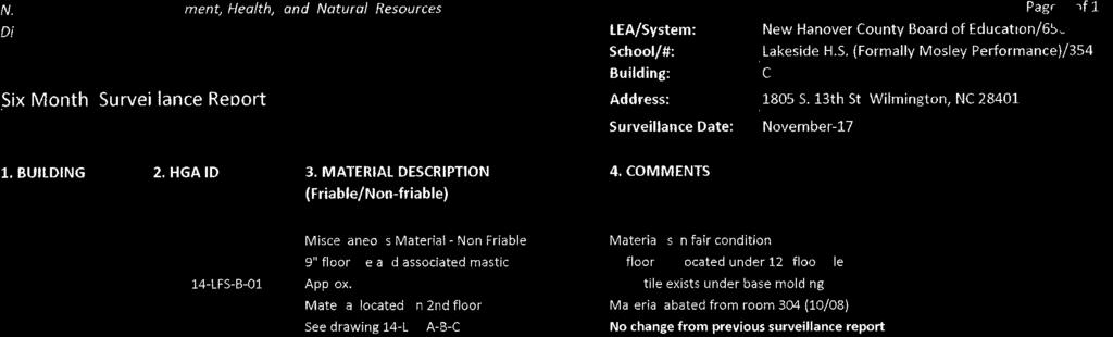
169
170

171
172
173
174
175 SECTION UNIT MASONRY ASSEMBLIES PART 1 - GENERAL 1.1 SUMMARY A. This Section includes unit masonry assemblies consisting of the following: 1. Concrete masonry units (CMUs). 2. Face brick. 3. Mortar and grout. 4. Ties and anchors. B. See Division 7 Section "Sheet Metal Flashing and Trim" for furnishing manufactured reglets installed in masonry joints for metal flashing. 1.2 SUBMITTALS A. Product Data: For each type of product indicated. B. Samples: For each type and color of exposed masonry units and colored mortars. C. Material Certificates: For each type of product indicated. Include statements of material properties indicating compliance with requirements including compliance with standards and type designations within standards. 1. For masonry units include material test reports substantiating compliance with requirements. D. Mix Designs: For each type of mortar and grout. Include description of type and proportions of ingredients. 1.3 QUALITY ASSURANCE A. Fire-Resistance Ratings: Where indicated, provide materials and construction identical to those of assemblies with fire-resistance ratings determined per ASTM E 119 by a testing and inspecting agency, by equivalent concrete masonry thickness, or by other means, as acceptable to authorities having jurisdiction. 1.4 PROJECT CONDITIONS A. Cold-Weather Requirements: Do not use frozen materials or materials mixed or coated with ice or frost. Do not build on frozen substrates. Remove and replace unit masonry damaged by frost or by freezing conditions. Comply with cold-weather construction requirements contained in ACI 530.1/ASCE 6/TMS 602. UNIT MASONRY Testing Department Upgrades
176 B. Hot-Weather Requirements: Comply with hot-weather construction requirements contained in ACI 530.1/ASCE 6/TMS 602. PART 2 - PRODUCTS 2.1 MANUFACTURERS A. In other Part 2 articles where titles below introduce lists, the following requirements apply to product selection: 1. Available Products: Subject to compliance with requirements, products that may be incorporated into the Work include, but are not limited to, products specified. 2. Products: Subject to compliance with requirements, provide one of the products specified. 3. Available Manufacturers: Subject to compliance with requirements, manufacturers offering products that may be incorporated into the Work include, but are not limited to, manufacturers specified. 4. Manufacturers: Subject to compliance with requirements, provide products by one of the manufacturers specified. 2.2 COLORS, TEXTURES, AND PATTERNS A. Exposed Face Brick: 3 5/8 x 7 5/8 x 2 ¼, modular. Coursing and pattern to match existing. Align new brick coursing with existing. Color, texture, size to match existing. 2.3 CONCRETE MASONRY UNITS (CMUs) A. Shapes: Provide special shapes for lintels, corners, jambs, sashes, movement joints, headers, bonding, and other special conditions. B. Concrete Masonry Units: ASTM C Unit Compressive Strength: Provide units with minimum average net-area compressive strength of 1,900 psi. 2. Weight Classification: Lightweight. 2.4 BRICK A. General: Provide shapes indicated and as follows: 1. New face brick shall match existing brick (color, texture, size). Submit sample for approval prior to start of construction. 2. For ends of sills and caps and for similar applications that would otherwise expose unfinished brick surfaces, provide units without cores or frogs and with exposed surfaces finished. UNIT MASONRY Testing Department Upgrades
177 3. Provide special shapes for applications where shapes produced by sawing would result in sawed surfaces being exposed to view. B. Face Brick: ASTM C 216, Grade SW, Type FBS. 1. Unit Compressive Strength: Provide units with minimum average net-area compressive strength of 3000 psi. 2. Initial Rate of Absorption: Less than 30 g/30 sq. in. per minute when tested per ASTM C Efflorescence: Provide brick that has been tested according to ASTM C 67 and is rated "not effloresced." 4. Size (Actual Dimensions): Match existing. 5. Application: Use where brick is exposed, unless otherwise indicated. 6. Color, Texture and Blend: Match existing building. 7. Acceptable Manufacturers: a. Roger Moore Brick Co. b. Palmetto Brick Company. c. Adams Products. 2.5 MORTAR AND GROUT MATERIALS A. Portland Cement: ASTM C 150, Type I or II, except Type III may be used for cold-weather construction. B. Hydrated Lime: ASTM C 207, Type S. C. Masonry Cement: ASTM C Products: a. Capital Materials Corporation; Flamingo Color Masonry Cement. b. Lehigh Cement Company; Lehigh White Masonry Cement. c. National Cement Company, Inc.; Coosa Masonry Cement. D. Mortar Pigments: Iron oxides and chromium oxides, compounded for use in mortar mixes. Use only pigments with a record of satisfactory performance in masonry mortar. 1. Products: a. Bayer Corporation, Industrial Chemicals Div.; Bayferrox Iron Oxide Pigments. b. Davis Colors; True Tone Mortar Colors. c. Solomon Grind-Chem Services, Inc.; SGS Mortar Colors. E. Colored Cement Product: Packaged blend made from portland cement and lime and mortar pigments, all complying with specified requirements, and containing no other ingredients. UNIT MASONRY Testing Department Upgrades
178 1. Formulate blend as required to produce color indicated or, if not indicated, as selected from manufacturer's standard colors. 2. Products: a. Colored Portland Cement-Lime Mix: 1) Holcim (US) Inc.; Rainbow Mortamix Custom Color Cement/Lime. 2) Lehigh Cement Company; Lehigh Custom Color Portland/Lime Cement. F. Aggregate for Mortar: ASTM C For joints less than 1/4 inch thick, use aggregate graded with 100 percent passing the No. 16 sieve. 2. Colored-Mortar Aggregates: Natural sand or crushed stone of color necessary to produce required mortar color. G. Aggregate for Grout: ASTM C 404. H. Epoxy Pointing Mortar: ASTM C 395, epoxy-resin-based material formulated for use as pointing mortar for structural-clay tile facing units. I. Cold-Weather Admixture: Nonchloride, noncorrosive, accelerating admixture complying with ASTM C 494/C 494M, Type C, and recommended by manufacturer for use in masonry mortar of composition indicated. 1. Products: a. Euclid Chemical Company (The); Accelguard 80. b. Grace Construction Products, a unit of W. R. Grace & Co. - Conn.; Morset. c. Sonneborn, Div. of ChemRex; Trimix-NCA. J. Water-Repellent Admixture: Liquid water-repellent mortar admixture intended for use with concrete masonry units, containing integral water repellent by same manufacturer. 1. Products: K. Water: Potable. a. Addiment Incorporated; Mortar Tite. b. Grace Construction Products, a unit of W. R. Grace & Co. - Conn.; Dry-Block Mortar Admixture. c. Master Builders, Inc. 2.6 REINFORCEMENT A. Uncoated Steel Reinforcing Bars: ASTM A 615/A 615M or ASTM A 996/A 996M, Grade 60. B. Masonry Joint Reinforcement: ASTM A 951; mill galvanized, carbon-steel wire for interior walls and hot-dip galvanized, carbon-steel wire for exterior walls. UNIT MASONRY Testing Department Upgrades
179 1. Wire Size for Side Rods: W2.8 or inch diameter. 2. Wire Size for Cross Rods: W2.8 or inch diameter. 3. Wire Size for Veneer Ties: W2.8 or inch diameter. 4. Spacing of Cross Rods, Tabs, and Cross Ties: Not more than 16 inches o.c. 5. Single-Wythe Masonry: Either ladder or truss type with single pair of side rods. 6. Multiwythe Masonry: a. Ladder type with 1 side rod at each face shell of hollow masonry units more than 4 inches in width, plus 1 side rod at each wythe of masonry 4 inches or less in width. b. Adjustable (two-piece) type, with one side rod at each face shell of backing wythe and with ties that extend into facing wythe. Ties engage eyes or slots in reinforcement and extend at least halfway through facing wythe but with at least 5/8-inch cover on outside face. Ties have hooks or clips to engage a continuous wire in the facing wythe. 7. Veneers Anchored with Seismic Masonry-Veneer Anchors: Single inch- diameter, hot-dip galvanized, carbon-steel continuous wire. 2.7 TIES AND ANCHORS A. Materials: 1. Hot-Dip Galvanized, Carbon-Steel Wire: ASTM A 82; with ASTM A 153/A 153M, Class B-2 coating. 2. Steel Sheet, Galvanized after Fabrication: ASTM A 1008/A 1008M, Commercial Steel, hot-dip galvanized after fabrication to comply with ASTM A 153/A 153M. 3. Steel Plates, Shapes, and Bars: ASTM A 36/A 36M. B. Wire Ties, General: Unless otherwise indicated, size wire ties to extend at least halfway through veneer but with at least 5/8-inch cover on outside face. Outer ends of wires are bent 90 degrees and extend 2 inches parallel to face of veneer. C. Individual Wire Ties: Rectangular units with closed ends and not less than 4 inches wide. 1. Wire: Fabricate from 3/16-inch- diameter, hot-dip galvanized steel wire. D. Adjustable Anchors for Connecting to Structure: Provide anchors that allow vertical or horizontal adjustment but resist tension and compression forces perpendicular to plane of wall. 1. Anchor Section for Welding to Steel Frame: Crimped 1/4-inch- diameter, hot-dip galvanized steel wire. 2. Tie Section: Triangular-shaped wire tie, sized to extend within 1 inch of masonry face, made from 0.25-inch- diameter, hot-dip galvanized steel wire. E. Rigid Anchors: Fabricate from steel bars 1-1/2 inches wide by 1/4 inch thick by 24 inches long, with ends turned up 2 inches or with cross pins. 1. Corrosion Protection: Hot-dip galvanized to comply with ASTM A 153/A 153M. UNIT MASONRY Testing Department Upgrades
180 F. Adjustable Masonry-Veneer Anchors 1. General: Provide anchors that allow vertical adjustment but resist tension and compression forces perpendicular to plane of wall, for attachment over sheathing to wood or metal studs, and as follows: a. Structural Performance Characteristics: Capable of withstanding a 100-lbf load in both tension and compression without deforming or developing play in excess of 0.05 inch. 2. Screw-Attached, Masonry-Veneer Anchors: Units consisting of a wire tie and a metal anchor section. a. Anchor Section: Rib-stiffened, sheet metal plate with screw holes top and bottom, and slotted holes for inserting wire tie. b. Fabricate sheet metal anchor sections from inch- thick, steel sheet, galvanized after fabrication. c. Wire Ties: Triangular-, rectangular-, or T-shaped wire ties fabricated from inch- diameter, hot-dip galvanized steel wire. d. Products: 1) Dayton Superior Corporation, Dur-O-Wal Division; D/A ) Heckmann Building Products Inc.; 315-D with ) Hohmann & Barnard, Inc.; DW-10HS. 2.8 EMBEDDED FLASHING MATERIALS A. Flexible Flashing: For flashing not exposed to the exterior, use the following, unless otherwise indicated: 1. Copper-Laminated Flashing: 7-oz./sq. ft. copper sheet bonded with asphalt between 2 layers of glass-fiber cloth. a. Products: 1) AFCO Products Inc.; Copper Fabric. 2) Hohmann & Barnard, Inc.; H & B C-Fab Flashing. 3) York Manufacturing, Inc.; York Copper Fabric Flashing. B. Solder and Sealants for Sheet Metal Flashings: As specified in Division 7 Section "Sheet Metal Flashing and Trim." C. Adhesives, Primers, and Seam Tapes for Flashings: Flashing manufacturer's standard products or products recommended by flashing manufacturer. UNIT MASONRY Testing Department Upgrades
181 2.9 MISCELLANEOUS MASONRY ACCESSORIES A. Compressible Filler: Premolded filler strips complying with ASTM D 1056, Grade 2A1; compressible up to 35 percent; formulated from neoprene, urethane or PVC. B. Preformed Control-Joint Gaskets: Made from styrene-butadiene-rubber compound, complying with ASTM D 2000, Designation M2AA-805 or PVC, complying with ASTM D 2287, Type PVC and designed to fit standard sash block and to maintain lateral stability in masonry wall. C. Bond-Breaker Strips: Asphalt-saturated, organic roofing felt complying with ASTM D 226, Type I (No. 15 asphalt felt). D. Weep/Vent Products: Use the following, unless otherwise indicated: 1. Cellular Plastic Weep/Vent: One-piece, flexible extrusion made from UV-resistant polypropylene copolymer, full height and width of head joint and depth 1/8 inch less than depth of outer wythe, in color selected from manufacturer's standard. a. Products: 1) Advanced Building Products Inc.; Mortar Maze weep vent. 2) Heckmann Building Products Inc.; No. 85 Cell Vent. 3) Hohmann & Barnard, Inc.; Quadro-Vent MASONRY CLEANERS A. Proprietary Acidic Cleaner: Manufacturer's standard-strength cleaner designed for removing mortar/grout stains from new masonry without damaging masonry. Use product approved for intended use by cleaner manufacturer and manufacturer of masonry units being cleaned. 1. Manufacturers: a. Diedrich Technologies, Inc. b. EaCo Chem, Inc. c. ProSoCo, Inc MORTAR AND GROUT MIXES A. General: Do not use admixtures, unless otherwise indicated. 1. Do not use calcium chloride in mortar or grout. 2. Limit cementitious materials in mortar for exterior masonry to portland cement and lime. 3. Add cold-weather admixture (if used) at same rate for all mortar that will be exposed to view, regardless of weather conditions, to ensure that mortar color is consistent. B. Mortar for Unit Masonry: Comply with ASTM C 270, Proportion Specification. C. Mortar for Unit Masonry: Comply with ASTM C 270, Property Specification. UNIT MASONRY Testing Department Upgrades
182 1. For masonry below grade or in contact with earth, use Type S. 2. For reinforced masonry, use Type S. 3. For mortar parge coats, use Type S. 4. For exterior, above-grade, load-bearing and non-load-bearing walls and parapet walls; for interior load-bearing walls; for interior non-load-bearing partitions; and for other applications where another type is not indicated, use Type N. 5. For interior non-load-bearing partitions, Type O may be used instead of Type N. D. Pigmented Mortar: Use colored cement product or select and proportion pigments with other ingredients to produce color required. Do not add pigments to colored cement products. 1. Mortar shall match existing. Provide sample for approval prior to construction. 2. Pigments shall not exceed 10 percent of portland cement by weight. 3. Pigments shall not exceed 5 percent of masonry cement by weight. E. Grout for Unit Masonry: Comply with ASTM C Use grout of type indicated or, if not otherwise indicated, of type (fine or coarse) that will comply with Table in ACI 530.1/ASCE 6/TMS 602 for dimensions of grout spaces and pour height. 2. Provide grout with a slump of 8 to 11 inches as measured according to ASTM C 143/C 143M. F. Epoxy Pointing Mortar: Mix epoxy pointing mortar to comply with mortar manufacturer's written instructions. PART 3 - EXECUTION 3.1 INSTALLATION, GENERAL A. Use full-size units without cutting if possible. If cutting is required, cut units with motor-driven saws; provide clean, sharp, unchipped edges. Allow units to dry before laying unless wetting of units is specified. Install cut units with cut surfaces and, where possible, cut edges concealed. B. Select and arrange units for exposed unit masonry to produce a uniform blend of colors and textures. C. Wetting of Brick: Wet brick before laying if initial rate of absorption exceeds 30 g/30 sq. in. per minute when tested per ASTM C 67. Allow units to absorb water so they are damp but not wet at time of laying. D. Comply with tolerances in ACI 530.1/ASCE 6/TMS 602 and with the following: 1. For conspicuous vertical lines, such as external corners, door jambs, reveals, and expansion and control joints, do not vary from plumb by more than 1/8 inch in 10 feet, 1/4 inch in 20 feet, or 1/2 inch maximum. UNIT MASONRY Testing Department Upgrades
183 2. For conspicuous horizontal lines, such as lintels, sills, parapets, and reveals, do not vary from level by more than 1/8 inch in 10 feet, 1/4 inch in 20 feet, or 1/2 inch maximum. 3.2 LAYING MASONRY WALLS A. Lay out walls in advance for accurate spacing of surface bond patterns with uniform joint thicknesses and for accurate location of openings, movement-type joints, returns, and offsets. Avoid using less-than-half-size units, particularly at corners, jambs, and, where possible, at other locations. B. Bond Pattern for Exposed Masonry: Unless otherwise indicated, lay exposed masonry in running bond; do not use units with less than nominal 4-inch horizontal face dimensions at corners or jambs. C. Built-in Work: As construction progresses, build in items specified in this and other Sections. Fill in solidly with masonry around built-in items. D. Fill space between steel frames and masonry solidly with mortar, unless otherwise indicated. E. Fill cores in hollow concrete masonry units with grout 24 inches under bearing plates, beams, lintels, posts, and similar items, unless otherwise indicated. 3.3 MORTAR BEDDING AND JOINTING A. Lay hollow brick and concrete masonry units as follows: 1. With face shells fully bedded in mortar and with head joints of depth equal to bed joints. 2. With webs fully bedded in mortar in all courses of piers, columns, and pilasters. 3. With webs fully bedded in mortar in grouted masonry, including starting course on footings. 4. With entire units, including areas under cells, fully bedded in mortar at starting course on footings where cells are not grouted. B. Lay solid masonry units with completely filled bed and head joints; butter ends with sufficient mortar to fill head joints and shove into place. Do not deeply furrow bed joints or slush head joints. C. Tool exposed joints slightly concave when thumbprint hard, using a jointer larger than joint thickness, unless otherwise indicated. D. Cut joints flush for masonry walls to receive plaster or other direct-applied finishes (other than paint), unless otherwise indicated. 3.4 CAVITY WALLS A. Bond wythes of cavity walls together using one of the following methods: UNIT MASONRY Testing Department Upgrades
184 1. Individual Metal Ties: Provide ties as shown installed in horizontal joints, but not less than one metal tie for 2.67 sq. ft. of wall area spaced not to exceed 16 inches o.c. horizontally and 16 inches o.c. vertically. Stagger ties in alternate courses. Provide additional ties within 12 inches of openings and space not more than 36 inches apart around perimeter of openings. At intersecting and abutting walls, provide ties at no more than 16 inches o.c. vertically. 2. Masonry Joint Reinforcement: Installed in horizontal mortar joints. a. Where bed joints of both wythes align, use ladder-type reinforcement extending across both wythes. b. Where bed joints of wythes do not align, use adjustable (two-piece) type reinforcement. c. Where one wythe is of clay masonry and the other of concrete masonry, use adjustable (two-piece) type reinforcement to allow for differential movement regardless of whether bed joints align. 3. Masonry Veneer Anchors: Comply with requirements for anchoring masonry veneers. B. Keep cavities clean of mortar droppings and other materials during construction. Bevel beds away from cavity, to minimize mortar protrusions into cavity. Do not attempt to trowel or remove mortar fins protruding into cavity. C. Coat cavity face of backup wythe to comply with Division 7 Section "Fluid Applied Air Barriers" D. Installing Cavity-Wall Insulation: Place small dabs of adhesive, spaced approximately 12 inches o.c. both ways, on inside face of insulation boards, or attach with plastic fasteners designed for this purpose. Fit insulation between wall ties and other confining obstructions, with edges butted tightly. Press units firmly against inside wythe of masonry. 3.5 MASONRY JOINT REINFORCEMENT A. General: Install in mortar with a minimum cover of 5/8 inch on exterior side of walls, 1/2 inch elsewhere. Lap reinforcement a minimum of 6 inches. B. Interrupt joint reinforcement at control and expansion joints, unless otherwise indicated. C. Provide continuity at wall intersections by using prefabricated T-shaped units. D. Provide continuity at corners by using prefabricated L-shaped units. 3.6 ANCHORING MASONRY VENEERS A. Anchor masonry veneers to wall framing concrete and masonry backup with masonry-veneer anchors to comply with the following requirements: 1. Fasten screw-attached anchors through sheathing to wall framing and to concrete and masonry backup with metal fasteners of type indicated. Use two fasteners. UNIT MASONRY Testing Department Upgrades
185 2. Embed connector sections and continuous wire in masonry joints. Provide not less than 2 inches of air space between back of masonry veneer and face of sheathing. 3. Locate anchor sections to allow maximum vertical differential movement of ties up and down. 4. Space anchors as indicated, but not more than 16 inches o.c. vertically and 16 inches o.c. horizontally with not less than 1 anchor for each 2.67 sq. ft. of wall area. Install additional anchors within 12 inches of openings and at intervals, not exceeding 36 inches, around perimeter. 3.7 FLASHING, WEEP HOLES, CAVITY DRAINAGE, AND VENTS A. General: Install embedded flashing and weep holes in masonry at shelf angles, lintels, ledges, other obstructions to downward flow of water in wall, and where indicated. Install weeps at shelf angles, ledges, and other obstructions to upward flow of air in cavities, and where indicated. B. Install flashing as follows, unless otherwise indicated: 1. Prepare masonry surfaces so they are smooth and free from projections that could puncture flashing. Where flashing is within mortar joint, place through-wall flashing on sloping bed of mortar and cover with mortar. Before covering with mortar, seal penetrations in flashing as recommended by flashing manufacturer. 2. At lintels and shelf angles, extend flashing a minimum of 6 inches into masonry at each end. At heads and sills, extend flashing 6 inches at ends and turn up not less than 2 inches to form end dams. 3. Install metal drip edges beneath flexible flashing at exterior face of wall. Stop flexible flashing 1/2 inch back from outside face of wall and adhere flexible flashing to top of metal drip edge. 4. Install metal flashing termination beneath flexible flashing at exterior face of wall. Stop flexible flashing 1/2 inch back from outside face of wall and adhere flexible flashing to top of metal flashing termination. C. Install weep holes in head joints in exterior wythes of first course of masonry immediately above embedded flashing and as follows: 1. Use or open head joints to form weep holes. 2. Space weep holes 24 inches o.c., unless otherwise indicated. 3. Cover cavity side of weep holes with plastic insect screening at cavities insulated with loose-fill insulation. D. Place cavity drainage material in cavities to comply with configuration requirements for cavity drainage material in Part 2 "Miscellaneous Masonry Accessories" Article. E. Install weeps in head joints in exterior wythes at spacing indicated. Use open head joints to form vents. 1. Close cavities off vertically and horizontally with blocking in manner indicated. Install through-wall flashing and weep holes above horizontal blocking. UNIT MASONRY Testing Department Upgrades
186 3.8 REINFORCED UNIT MASONRY INSTALLATION A. Temporary Formwork and Shores: Construct formwork and shores as needed to support reinforced masonry elements during construction. 1. Construct formwork to provide shape, line, and dimensions of completed masonry as indicated. Make forms sufficiently tight to prevent leakage of mortar and grout. Brace, tie, and support forms to maintain position and shape during construction and curing of reinforced masonry. 2. Do not remove forms and shores until reinforced masonry members have hardened sufficiently to carry their own weight and other temporary loads that may be placed on them during construction. B. Placing Reinforcement: Comply with requirements in ACI 530.1/ASCE 6/TMS 602. C. Grouting: Do not place grout until entire height of masonry to be grouted has attained enough strength to resist grout pressure. 1. Comply with requirements in ACI 530.1/ASCE 6/TMS 602 for cleanouts and for grout placement, including minimum grout space and maximum pour height. 2. Limit height of vertical grout pours to not more than 60 inches. 3.9 CLEANING A. In-Progress Cleaning: Clean unit masonry as work progresses by dry brushing to remove mortar fins and smears before tooling joints. B. Final Cleaning: After mortar is thoroughly set and cured, clean exposed masonry as follows: 1. Test cleaning methods on sample wall panel; leave one-half of panel uncleaned for comparison purposes. 2. Protect adjacent surfaces from contact with cleaner. 3. Wet wall surfaces with water before applying cleaners; remove cleaners promptly by rinsing surfaces thoroughly with clear water. 4. Clean brick by bucket-and-brush hand-cleaning method described in BIA Technical Notes Clean masonry with a proprietary acidic cleaner applied according to manufacturer's written instructions. 6. Clean concrete masonry by cleaning method indicated in NCMA TEK 8-2A applicable to type of stain on exposed surfaces MASONRY WASTE DISPOSAL A. Waste Disposal as Fill Material: Dispose of clean masonry waste, including excess or soilcontaminated sand, waste mortar, and broken masonry units, by crushing and mixing with fill material as fill is placed. 1. Do not dispose of masonry waste as fill. UNIT MASONRY Testing Department Upgrades
187 2. Remove excess clean masonry waste and other masonry waste, and legally dispose of off Owner's property. END OF SECTION UNIT MASONRY Testing Department Upgrades
188
189 SECTION MISCELLANEOUS ROUGH CARPENTRY PART 1 - GENERAL 1.1 RELATED DOCUMENTS A. Drawings and general provisions of the Contract, including General and Supplementary Conditions and Division 1 Specification Sections, apply to this Section. 1.2 SUMMARY A. This Section includes the following: 1. Wood blocking and nailers. a. For miscellaneous concealed blocking. b. Rooftop equipment bases and support curbs. 2. Metal Framing anchors. 3. Plywood backing panels. 1.3 DEFINITIONS A. Exposed Framing: Framing not concealed by other construction. B. Dimension Lumber: Lumber of 2 inches nominal or greater but less than 5 inches nominal in least dimension. C. Lumber grading agencies, and the abbreviations used to reference them, include the following: 1. NeLMA: Northeastern Lumber Manufacturers' Association. 2. NLGA: National Lumber Grades Authority. 3. SPIB: The Southern Pine Inspection Bureau. 4. WWPA: Western Wood Products Association. 1.4 SUBMITTALS 1. Include data for wood-preservative treatment from chemical treatment manufacturer and certification by treating plant that treated materials comply with requirements. Indicate type of preservative used and net amount of preservative retained. 2. Include copies of warranties from chemical treatment manufacturers for each type of treatment. 3. For composite wood products, documentation indicating that product contains no urea formaldehyde. MISCELLANEOUS ROUGH CARPENTRY Testing Department Upgrades
190 4. Material Certificates: For dimension lumber specified to comply with minimum allowable unit stresses. Indicate species and grade selected for each use and design values approved by the ALSC Board of Review. 1.5 DELIVERY, STORAGE, AND HANDLING A. H.Stack lumber flat with spacers between each bundle to provide air circulation. Provide for air circulation around stacks and under coverings. PART 2 - PRODUCTS 2.1 WOOD PRODUCTS, GENERAL A. A.Lumber: DOC PS 20 and applicable rules of grading agencies indicated. If no grading agency is indicated, provide lumber that complies with the applicable rules of any rules-writing agency certified by the ALSC Board of Review. Provide lumber graded by an agency certified by the ALSC Board of Review to inspect and grade lumber under the rules indicated. 1. Factory mark each piece of lumber with grade stamp of grading agency. 2. Provide dressed lumber, S4S, unless otherwise indicated. 2.2 WOOD-PRESERVATIVE-TREATED LUMBER A. Preservative Treatment by Pressure Process: AWPA C2, except that lumber that is not in contact with the ground and is continuously protected from liquid water may be treated according to AWPA C31 with inorganic boron (SBX). 1. Preservative Chemicals: Acceptable to authorities having jurisdiction and containing no arsenic or chromium. B. Kiln-dry lumber after treatment to a maximum moisture content of 19 percent. Do not use material that is warped or does not comply with requirements for untreated material. C. Application: Treat all rough carpentry, unless otherwise indicated. 1. Wood nailers, curbs, blocking, stripping, and similar members in connection with roofing, flashing, vapor barriers, and waterproofing. 2. Wood sills, blocking, and similar concealed members in contact with masonry or concrete. 3. Wood framing and furring attached directly to the interior of below-grade exterior masonry or concrete walls. 4. Wood deck framing. 2.3 FIRE-RETARDANT-TREATED MATERIALS A. Fire-Retardant-Treated Lumber and Plywood by Pressure Process: Products with a flame spread index of 25 or less when tested according to ASTM E 84, and with no evidence of MISCELLANEOUS ROUGH CARPENTRY Testing Department Upgrades
191 significant progressive combustion when the test is extended an additional 20 minutes, and with the flame front not extending more than 10.5 feet (3.2 m) beyond the centerline of the burners at any time during the test. 1. Exterior Type: Treated materials shall comply with requirements specified above for fire-retardant-treated lumber and plywood by pressure process after being subjected to accelerated weathering according to ASTM D Use for exterior locations and where indicated. 2. Interior Type A: Treated materials shall have a moisture content of 28 percent or less when tested according to ASTM D 3201 at 92 percent relative humidity. Use where exterior type is not indicated. 3. Design Value Adjustment Factors: Treated lumber shall be tested according ASTM D 5664, and design value adjustment factors shall be calculated according to ASTM D [For enclosed roof framing, framing in attic spaces, and where high temperature fire-retardant treatment is indicated, provide material with adjustment factors of not less than 0.85 modulus of elasticity and 0.75 for extreme fiber in bending for Project's climatological zone. B. Kiln-dry lumber after treatment to a maximum moisture content of 19 percent. Kiln-dry plywood after treatment to a maximum moisture content of 15 percent. C. Identify fire-retardant-treated wood with appropriate classification marking of testing and inspecting agency acceptable to authorities having jurisdiction. D. Application: Items indicated on Drawings, and the following: 1. Concealed blocking. 2. Wood cants, nailers, curbs, equipment support bases, blocking, and similar members in connection with roofing. 3. Plywood backing panels. 2.4 MISCELLANEOUS LUMBER A. I. General: Provide miscellaneous lumber indicated and lumber for support or attachment of other construction, including the following: 1. Blocking. 2. Nailers. 3. Furring. B. For items of dimension lumber size, provide Construction or No. 2 grade lumber with 15 percent maximum moisture content of any species. C. For exposed or concealed boards, provide lumber with 15 percent maximum moisture content and any of the following species and grades: 1. Mixed southern pine, No. 2 grade; SPIB. 2. Hem-fir or hem-fir (north), Construction or 2 Common grade; NLGA, WCLIB, or WWPA. MISCELLANEOUS ROUGH CARPENTRY Testing Department Upgrades
192 3. Spruce-pine-fir (south) or spruce-pine-fir, Construction or 2 Common grade; NeLMA, NLGA, WCLIB, or WWPA. 4. Eastern softwoods, No. 2 Common grade; NeLMA. 5. Northern species, No. 2 Common grade; NLGA. 6. Western woods, Construction or No. 2 Common grade; WCLIB or WWPA. D. For blocking not used for attachment of other construction, Utility, Stud, or No. 3 grade lumber of any species may be used provided that it is cut and selected to eliminate defects that will interfere with its attachment and purpose. E. For blocking and nailers used for attachment of other construction, select and cut lumber to eliminate knots and other defects that will interfere with attachment of other work. F. For furring strips for installing plywood panels, select boards with no knots capable of producing bent-over nails and damage to paneling. 2.5 PLYWOOD BACKING PANELS A. Telephone and Electrical Equipment Backing Panels: DOC PS 1, Exposure 1, C-D Plugged, fire-retardant treated, in thickness indicated or, if not indicated, not less than 1/2-inch nominal thickness. 2.6 FASTENERS A. General: Provide fasteners of size and type indicated that comply with requirements specified in this Article for material and manufacture. 1. Where rough carpentry is exposed to weather, in ground contact, pressure-preservative treated, or in area of high relative humidity, provide fasteners of Type 304 stainless steel. B. Nails, Brads, and Staples: ASTM F C. Power-Driven Fasteners: NES NER-272. D. Wood Screws: ASME B E. Lag Bolts: ASME B F. Bolts: Steel bolts complying with ASTM A 307, Grade A; with ASTM A 563 hex nuts and, where indicated, flat washers. G. Expansion Anchors: Anchor bolt and sleeve assembly of material indicated below with capability to sustain, without failure, a load equal to 6 times the load imposed when installed in unit masonry assemblies and equal to 4 times the load imposed when installed in concrete as determined by testing per ASTM E 488 conducted by a qualified independent testing and inspecting agency. 1. Material: Carbon-steel components, zinc plated to comply with ASTM B 633, Class Fe/Zn 5. MISCELLANEOUS ROUGH CARPENTRY Testing Department Upgrades
193 2. Material: Stainless steel with bolts and nuts complying with ASTM F 593 and ASTM F 594, Alloy Group 1 or METAL FRAMING ANCHORS A. Manufacturers: Subject to compliance with requirements, provide products by one of the following: 1. Cleveland Steel Specialty Co. 2. KC Metals Products, Inc. 3. Phoenix Metal Products, Inc. 4. Simpson Strong-Tie Co., Inc. 5. USP Structural Connectors. B. Allowable Design Loads: Provide products with allowable design loads, as published by manufacturer, that meet or exceed those indicated. Manufacturer's published values shall be determined from empirical data or by rational engineering analysis and demonstrated by comprehensive testing performed by a qualified independent testing agency. C. Galvanized-Steel Sheet: Hot-dip, zinc-coated steel sheet complying with ASTM A 653/A 653M, G60 (Z180) coating designation. 1. Use for interior locations unless otherwise indicated. D. Hot-Dip, Heavy-Galvanized Steel Sheet: ASTM A 653/A 653M; structural steel (SS), highstrength low-alloy steel Type A (HSLAS Type A), or high-strength low-alloy steel Type B (HSLAS Type B); G185 (Z550) coating designation; and not less than inch (0.9 mm) thick. 1. Use for wood-preservative-treated lumber and where indicated. E. Joist Hangers: U-shaped joist hangers with 2-inch- long seat and 1-1/4-inch-wide nailing flanges at least 85 percent of joist depth. 1. Thickness: inch. F. I-Joist Hangers: U-shaped joist hangers with 2-inch- (50-mm-) long seat and 1-1/4-inch- (32- mm-) wide nailing flanges full depth of joist. Nailing flanges provide lateral support at joist top chord. 1. Thickness: inch. G. Top Flange Hangers: U-shaped joist hangers, full depth of joist, formed from metal strap with tabs bent to extend over and be fastened to supporting member. 1. Strap Width: 1-1/2 inches. 2. Thickness: inch. H. Post Bases: Adjustable-socket type for bolting in place with standoff plate to raise post 1 inch above base and with 2-inch-minimum side cover, socket inch thick, and standoff and adjustment plates inch thick. MISCELLANEOUS ROUGH CARPENTRY Testing Department Upgrades
194 I. Joist Ties: Flat straps, with holes for fasteners, for tying joists together over supports. 1. Width: 1-1/4 inches. 2. Thickness: inch. 3. Length: As indicated. J. Fasteners: Use connector manufacturer s stainless steel screws, bolts and specialty anchors, designed to comply with the loading and penetration required for the proper performance of the hanger or support. 2.8 MISCELLANEOUS MATERIALS A. Adhesives for Gluing Furring and Sleepers to Concrete or Masonry: Formulation complying with ASTM D 3498 that is approved for use indicated by adhesive manufacturer. 1. Use adhesives that have a VOC content of 70g/L or less when calculated according to 40 CFR 59, Subpart D (EPA Method 24). PART 3 - EXECUTION 3.1 INSTALLATION, GENERAL A. Set rough carpentry to required levels and lines, with members plumb, true to line, cut, and fitted. Fit rough carpentry to other construction; scribe and cope as needed for accurate fit. Locate furring, nailers, blocking, and similar supports to comply with requirements for attaching other construction. B. Framing Standard: Comply with AF&PA's "Details for Conventional Wood Frame Construction", unless otherwise indicated. C. Provide blocking and framing as indicated and as required to support facing materials, fixtures, specialty items, and trim. 1. Provide metal clips for fastening gypsum board or lath at corners and intersections where framing or blocking does not provide a surface for fastening edges of panels. Space clips not more than 16 inches o.c. 2. Fire block concealed spaces behind combustible cornices and exterior trim at not more than 20 feet o.c. D. Sort and select lumber so that natural characteristics will not interfere with installation or with fastening other materials to lumber. Do not use materials with defects that interfere with function of member or pieces that are too small to use with minimum number of joints or optimum joint arrangement. E. Comply with AWPA M4 for applying field treatment to cut surfaces of preservative-treated lumber. 1. Use inorganic boron for items that are continuously protected from liquid water. 2. Use copper naphthenate for items not continuously protected from liquid water. MISCELLANEOUS ROUGH CARPENTRY Testing Department Upgrades
195 F. Securely attach rough carpentry work to substrate by anchoring and fastening, complying with the following: 1. NES NER-272 for power-driven fasteners. G. Use common wire nails, unless otherwise indicated. Select fasteners of size that will not fully penetrate members where opposite side will be exposed to view or will receive finish materials. Make tight connections between members. Install fasteners without splitting wood; do not countersink nail heads, unless otherwise indicated. 3.2 WOOD BLOCKING AND NAILER INSTALLATION A. Install where indicated and where required for screeding or attaching other work. Form to shapes indicated and cut as required for true line and level of attached work. Coordinate locations with other work involved. B. Attach items to substrates to support applied loading. Recess bolts and nuts flush with surfaces, unless otherwise indicated. 3.3 WOOD FURRING INSTALLATION A. Install level and plumb with closure strips at edges and openings. Shim with wood as required for tolerance of finish work. B. Furring to Receive Plywood Backing panels: Install 1-by-3-inch nominal- size furring vertically at 24 inches o.c. 3.4 PROTECTION A. Protect wood that has been treated with inorganic boron (SBX) from weather. If, despite protection, inorganic boron-treated wood becomes wet, apply EPA-registered borate treatment. Apply borate solution by spraying to comply with EPA-registered label. B. Protect rough carpentry from weather. If, despite protection, rough carpentry becomes wet, apply EPA-registered borate treatment. Apply borate solution by spraying to comply with EPAregistered label. END OF SECTION MISCELLANEOUS ROUGH CARPENTRY Testing Department Upgrades
196
197 SECTION FLUID-APPLIED MEMBRANE AIR and WATER BARRIERS PART 1 - GENERAL 1.1 RELATED DOCUMENTS A. Drawings and general provisions of the Contract, including General and Supplementary Conditions and Division 01 Specification Sections, apply to this Section. 1.2 SUMMARY A. This Section includes the following: 1. Fluid-applied membrane air barrier, vapor permeable. 2. Termination Mastic. 3. Auxiliary materials. 1.3 DEFINITIONS A. ABAA: Air Barrier Association of America. B. Air Barrier Assembly: The collection of air barrier materials and auxiliary materials applied to an opaque wall, including joints and junctions to abutting construction, to control air movement through the wall. 1.4 PERFORMANCE REQUIREMENTS A. General: Air barrier shall be capable of performing as a continuous vapor-retarding or vapor permeable air barrier as application warrants, and as a liquid-water drainage plane flashed to discharge to the exterior incidental condensation or water penetration. Air barrier assemblies shall be capable of accommodating substrate movement and of sealing substrate expansion and control joints, construction material changes, and transitions at perimeter conditions without deterioration and air leakage exceeding specified limits. B. Air Barrier Assembly Air Leakage: Not to exceed 0.01 cfm x sq. ft. of surface area at 1.57 lbf/sq. ft.; ASTM E SUBMITTALS A. Product Data: Include manufacturer's written instructions for evaluating, preparing, and treating substrate; technical data; and tested physical and performance properties of air barrier. FLUID-APPLIED MEMBRANE AIR AND WATER BARRIERS Testing Department Upgrades
198 B. Shop Drawings: Show locations and extent of air barrier. Include details for substrate joints and cracks, counterflashing strip, penetrations, inside and outside corners, terminations, and tieins with adjoining construction. 1. Include details of interfaces with other materials that form part of air barrier. C. Product Certificates: For air barriers, certifying compatibility of air barrier and accessory materials with Project materials that connect to or that come in contact with the barrier; signed by product manufacturer. D. Qualification Data: For Applicator. E. Product Test Reports: Based on evaluation of comprehensive tests performed by a qualified testing agency, for air barriers. 1.6 QUALITY ASSURANCE A. Applicator Qualifications: A firm experienced in applying air barrier materials similar in material, design, and extent to those indicated for this Project, whose work has resulted in applications with a record of successful in-service performance. B. Mockups: Before beginning installation of air barrier, assign area of in-place construction to act as a mockup of the exterior wall assembly of approximately 50 sq. ft., incorporating backup wall construction, external cladding, insulation, and flashing to demonstrate surface preparation, crack and joint treatment, and sealing of gaps, terminations, and penetrations of air barrier membrane. 1. Coordinate construction of mockup to permit inspection by Owner's testing agency of air barrier before external insulation and cladding is installed. 2. If Architect determines mockups do not comply with requirements, reconstruct mockups and apply air barrier until mockups are approved. 3. Approved mockups may become part of the completed Work if undisturbed at time of Substantial Completion. C. The air barrier shall be joined in an airtight and flexible manner to the air barrier material of adjacent systems, allowing for the relative movement of systems due to thermal and moisture variations and creep. Connection shall be made between: 1. Foundation and walls. 2. Walls and windows or doors. 3. Different wall systems. 4. Wall and roof. 5. Wall and roof over unconditioned space. 6. Walls, floor and roof across construction, control and expansion joints. 7. Walls, floors and roof to utility, pipe and duct penetrations. D. Preinstallation Conference: Conduct conference at Project site. FLUID-APPLIED MEMBRANE AIR AND WATER BARRIERS Testing Department Upgrades
199 1. Include installers of other construction connecting to air barrier, including roofing, waterproofing, architectural precast concrete, masonry, sealants, windows, glazed curtain walls, and door frames. 2. Review air barrier requirements including surface preparation, substrate condition and pretreatment, minimum substrate curing period, forecasted weather conditions, special details and sheet flashings, mockups, installation procedures, sequence of installation, testing and inspecting procedures, and protection and repairs. 1.7 DELIVERY, STORAGE, AND HANDLING A. Store liquid materials in their original undamaged packages in a clean, dry, protected location and within temperature range required by air barrier manufacturer. B. Remove and replace liquid materials that cannot be applied within their stated shelf life. C. Store rolls according to manufacturer's written instructions. D. Protect stored materials from direct sunlight. 1.8 PROJECT CONDITIONS A. Environmental Limitations: Apply air barrier within the range of ambient and substrate temperatures recommended by air barrier manufacturer. Protect substrates from environmental conditions that affect performance of air barrier. Do not apply air barrier to a damp or wet substrate or during snow, rain, fog, or mist. PART 2 - PRODUCTS 2.1 FLUID-APPLIED MEMBRANE AIR BARRIER A. Fluid-Applied, Vapor-Permeable Membrane Air Barrier: Elastomeric, modified bituminous or Synthetic polymer membrane. 1. Basis of Design: Provide Tremco, Inc., ExoAir 220. Subject to compliance with requirements, provide comparable products by one of the following: a. Henry Company; Air-Bloc 06 WB b. Grace W. R. & Co.; Perm-A-Barrier VP c. Meadows, W. R. Inc. d. Carlisle Coatings & Waterproofing, Inc. 2. Physical and Performance Properties: a. Membrane Air Permeance: Not to exceed cfm/ sq. ft. of surface area at 1.57-lbf/sq. ft. pressure difference; ASTM E FLUID-APPLIED MEMBRANE AIR AND WATER BARRIERS Testing Department Upgrades
200 b. Vapor permeance: Not to exceed 13 perms; ASTM E 96. B. Where air barrier membranes are to be exposed to UV degradation for a period of more than 30 days, use manufacturer s UV resistant formulations. 2.2 AUXILIARY MATERIALS A. General: Auxiliary materials recommended by air barrier manufacturer for intended use and compatible with air barrier membrane. Liquid-type auxiliary materials shall comply with VOC limits of authorities having jurisdiction. B. Primer: Liquid waterborne primer recommended for substrate by manufacturer of air barrier material. C. Counterflashing Strip: Modified bituminous, 40-mil- thick, self-adhering sheet consisting of 32 mils of rubberized asphalt laminated to an 8-mil- thick, crosslaminated polyethylene film with release liner backing. D. Modified Bituminous Strip: Vapor-retarding, 40-mil- thick, smooth-surfaced, self-adhering; consisting of 36 mils of rubberized asphalt laminated to a 4-mil- thick polyethylene film with release liner backing. E. Joint Reinforcing Strip: Air barrier manufacturer's glass-fiber-mesh tape. F. Substrate Patching Membrane: Manufacturer's standard trowel-grade substrate filler. G. Adhesive and Tape: Air barrier manufacturer's standard adhesive and pressure-sensitive adhesive tape. H. Sprayed Polyurethane Foam Sealant: Refer to Division 07 Section Thermal Insulation. Use primer and noncorrosive substrate cleaner recommended by foam sealant manufacturer. I. Modified Bituminous Transition Strip: Vapor-retarding, 40-mil- thick, smooth-surfaced, selfadhering; consisting of 36 mils of rubberized asphalt laminated to a 4-mil- thick polyethylene film with release liner backing. J. Elastomeric Flashing Sheet: ASTM D 2000, 2BC415 to 3BC620, minimum 50- to 65-milthick, cured sheet neoprene with manufacturer's recommended contact adhesives and lap sealant with stainless-steel termination bars and fasteners. FLUID-APPLIED MEMBRANE AIR AND WATER BARRIERS Testing Department Upgrades
201 K. Preformed Silicone-Sealant Extrusion: Manufacturer's standard system consisting of cured lowmodulus silicone extrusion, sized to fit opening widths, with a single-component, neutralcuring, Class 100/50 (low-modulus) silicone sealant for bonding extrusions to substrates. L. Joint Sealant: ASTM C 920, single-component, neutral-curing silicone; Class 100/50 (lowmodulus), Grade NS, Use NT related to exposure, and, as applicable to joint substrates indicated, Use O. Comply with Division 07 Section "Joint Sealants." M. Termination Mastic: Air barrier manufacturer s termination mastic. 1. Basis of Design: ExoAir Termination Mastic PART 3 - EXECUTION 3.1 EXAMINATION A. Examine substrates, areas, and conditions, with Installer present, for compliance with requirements and other conditions affecting performance. 1. Verify that substrates are sound and free of oil, grease, dirt, excess mortar, or other contaminants. 2. Verify that masonry joints are flush and completely filled with mortar. 3. Proceed with installation only after unsatisfactory conditions have been corrected. 3.2 SURFACE PREPARATION A. Clean, prepare, treat, and seal substrate according to manufacturer's written instructions. Provide clean, dust-free, and dry substrate for air barrier application. B. Mask off adjoining surfaces not covered by air barrier to prevent spillage and overspray affecting other construction. C. Remove grease, oil, bitumen, form-release agents, paints, curing compounds, and other penetrating contaminants or film-forming coatings from concrete. D. Remove fins, ridges, mortar, and other projections and fill honeycomb, aggregate pockets, holes, and other voids with substrate patching membrane. E. Remove excess mortar from masonry ties, shelf angles, and other obstructions. FLUID-APPLIED MEMBRANE AIR AND WATER BARRIERS Testing Department Upgrades
202 F. At changes in substrate plane, apply sealant or termination mastic beads at sharp corners and edges to form a smooth transition from one plane to another. G. Cover gaps in substrate plane and form a smooth transition from one substrate plane to another with stainless-steel sheet mechanically fastened to structural framing to provide continuous support for air barrier. 3.3 JOINT TREATMENT A. Concrete and Masonry: Prepare, treat, rout, and fill joints and cracks in substrate according to ASTM C 1193 and air barrier manufacturer's written instructions. Remove dust and dirt from joints and cracks complying with ASTM D 4258 before coating surfaces. 1. Prime substrate and apply a single thickness of preparation coat strip extending a minimum of 3 inches along each side of joints and cracks. Apply a double thickness of air barrier membrane and embed a joint reinforcing strip in preparation coat. B. Gypsum or Plywood Sheathing: Fill joints greater than 1/4 inch with sealant according to ASTM C 1193 and with air barrier manufacturer's written instructions. Apply first layer of fluid air barrier membrane at joints. Tape joints with joint reinforcing strip after first layer is dry. Apply a second layer of fluid air barrier membrane over joint reinforcing strip. 3.4 TRANSITION STRIP INSTALLATION A. Install strips, transition strips, and auxiliary materials according to air barrier manufacturer's written instructions to form a seal with adjacent construction and maintain a continuous air barrier. 1. Coordinate the installation of air barrier with installation of roofing membrane and base flashing to ensure continuity of air barrier with roofing membrane. 2. Install modified bituminous strip on roofing membrane or base flashing so that a minimum of 3 inches of coverage is achieved over both substrates. 3. Ensure that all wood blocking intended to support window frame systems is fully in place prior to placing base flashings at openings. B. Apply primer to substrates at required rate and allow to dry. Limit priming to areas that will be covered by air barrier sheet in same day. Reprime areas exposed for more than 24 hours. 1. Prime glass-fiber-surfaced gypsum sheathing with number of prime coats needed to achieve required bond, with adequate drying time between coats. C. Connect and seal exterior wall air barrier membrane continuously to roofing membrane air barrier, concrete below-grade structures, floor-to floor construction, exterior glazing and window systems, glazed curtain-wall systems, storefront systems, exterior louvers, exterior door framing, and other construction used in exterior wall openings, using accessory materials. FLUID-APPLIED MEMBRANE AIR AND WATER BARRIERS Testing Department Upgrades
203 D. At end of each working day, seal top edge of strips and transition strips to substrate with termination mastic. E. Apply joint sealants forming part of air barrier assembly within manufacturer's recommended application temperature ranges. Consult manufacturer when sealant cannot be applied within these temperature ranges. F. Wall Openings: Prime concealed perimeter frame surfaces of windows, curtain walls, storefronts, and doors. Apply modified bituminous transition strip so that a minimum of 3 inches of coverage is achieved over both substrates. Maintain 3 inches of full contact over firm bearing to perimeter frames with not less than 1 inch of full contact. 1. Modified Bituminous Transition Strip: Roll firmly to enhance adhesion. 2. Elastomeric Flashing Sheet: Apply adhesive to wall, frame, and flashing sheet. Install flashing sheet and termination bars, fastened at 6 inches o.c. Apply lap sealant over exposed edges and on cavity side of flashing sheet. G. Fill gaps in perimeter frame surfaces of windows, curtain walls, storefronts, and doors, and miscellaneous penetrations of air barrier membrane with foam sealant. H. Seal strips and transition strips around masonry reinforcing or ties and penetrations with termination mastic. I. Seal top of through-wall flashings to air barrier with an additional 6-inch- wide, modified bituminous strip. J. Seal exposed edges of strips at seams, cuts, penetrations, and terminations not concealed by metal counterflashings or ending in reglets with termination mastic. K. Repair punctures, voids, and deficient lapped seams in strips and transition strips. Slit and flatten fishmouths and blisters. Patch with transition strips extending 6 inches beyond repaired areas in strip direction. 3.5 AIR BARRIER MEMBRANE INSTALLATION A. Apply air barrier membrane to form a seal with strips and transition strips and to achieve a continuous air barrier according to air barrier manufacturer's written instructions. B. Apply air barrier membrane within manufacturer's recommended application temperature ranges. FLUID-APPLIED MEMBRANE AIR AND WATER BARRIERS Testing Department Upgrades
204 C. Apply primer to substrates at required rate and allow to dry. Limit priming to areas that will be covered by air barrier sheet in same day. Reprime areas exposed for more than 24 hours. 1. Prime glass-fiber-surfaced gypsum sheathing with number of prime coats needed to achieve required bond, with adequate drying time between coats. D. Apply a continuous unbroken air barrier to substrates according to the following minimum thickness. Apply membrane in full contact around protrusions such as masonry ties. 1. Vapor-Permeable Membrane Air Barrier: mils wet, no less than 47 mils dry thickness. E. Apply strip and transition strip a minimum of 1 inch onto cured air membrane or strip and transition strip over cured air membrane overlapping 3 inches onto each surface according to air barrier manufacturer's written instructions. F. Do not cover air barrier until it has been tested and inspected by Owner's testing agency. G. Correct deficiencies in or remove air barrier that does not comply with requirements; repair substrates and reapply air barrier components. 3.6 FIELD QUALITY CONTROL A. Testing Agency: Owner will engage a qualified testing agency to perform tests and inspections and prepare test reports. B. Inspections: Air barrier materials and installation are subject to inspection for compliance with requirements. Inspections may include the following: 1. Continuity of air barrier system has been achieved throughout the building envelope with no gaps or holes. 2. Continuous structural support of air barrier system has been provided. 3. Masonry and concrete surfaces are smooth, clean and free of cavities, protrusions, and mortar droppings. 4. Site conditions for application temperature and dryness of substrates have been maintained. 5. Maximum exposure time of materials to UV deterioration has not been exceeded. 6. Surfaces have been primed, if applicable. 7. Laps in strips and transition strips have complied with minimum requirements and have been shingled in the correct direction (or mastic has been applied on exposed edges), with no fishmouths. 8. Termination mastic has been applied on cut edges. 9. Strips and transition strips have been firmly adhered to substrate. 10. Compatible materials have been used. 11. Transitions at changes in direction and structural support at gaps have been provided. FLUID-APPLIED MEMBRANE AIR AND WATER BARRIERS Testing Department Upgrades
205 12. Connections between assemblies (membrane and sealants) have complied with requirements for cleanliness, preparation and priming of surfaces, structural support, integrity, and continuity of seal. 13. All penetrations have been sealed. C. Tests: Testing to be performed will be determined by Owner's testing agency from among the following tests: 1. Qualitative Testing: Air barrier assemblies will be tested for evidence of air leakage according to ASTM E 1186, chamber pressurization or depressurization with smoke tracers. 2. Quantitative Air Leakage Testing: Testing not to exceed the test pressure differential, positive and negative, indicated in "Performance Requirements" Article for air barrier assembly air leakage according to ASTM E 283. D. Remove and replace deficient air barrier components and retest as specified above. 3.7 CLEANING AND PROTECTION A. Protect air barrier system from damage during application and remainder of construction period, according to manufacturer's written instructions. 1. Protect air barrier from exposure to UV light and harmful weather exposure as required by manufacturer. Remove and replace air barrier exposed for more than 30 days unless UV resistant formulations were used. 2. Protect air barrier from contact with creosote, uncured coal-tar products, TPO, EPDM, flexible PVC membranes, and sealants not approved by air barrier manufacturer. B. Clean spills, stains, and soiling from construction that would be exposed in the completed work using cleaning agents and procedures recommended by manufacturer of affected construction. C. Remove masking materials after installation. END OF SECTION FLUID-APPLIED MEMBRANE AIR AND WATER BARRIERS Testing Department Upgrades
206
207 SECTION THERMOPLASTIC SINGLE-PLY ROOFING PART 1 GENERAL 1.01 WORK INCLUDED A. Install a fully adhered, thermoplastic membrane and cover board over adhered rigid insulation and flashings to provide a permanently watertight system RELATED DOCUMENTS A. Drawings and general provisions of the Contract, including General and Supplementary Conditions and Specification Sections, apply to this Section, including but not limited to: 1. Miscellaneous Rough Carpentry Section Sheet Metal Flashing and Trim - Section REFERENCES A. Refer to the following references, current edition for specification compliance: 1. NC State Building Code. 2. ASTM International. 3. National Roofing Contractors Association (NRCA). 4. Underwriters Laboratory (UL). 5. FM Global. 6. Single Ply Roofing Institute SUBMITTALS A. Refer to Section Submittal Procedures for Submittals. B. Latest edition of the Manufacturer s current material specifications and installation instructions. C. Manufacturer s Product Data Sheets for all materials specified certifying material complies with all specified requirements. D. Submit documentation of approved, tested roof system to meet the specified requirements for the following: 1. Wind Loads: Reference design loads on drawings for structural loading requirements. Roof shall meet Section 6, ASCE UL Fire Resistance Rating. 3. Shop drawing of roof plan showing fastening requirements for each roof sector and each roof zone. a. Include structural analysis data signed and sealed by a qualified structural engineer registered in the state of North Carolina responsible for their preparation. Analysis shall include sealed Section 6, ACSE 7 calculations. THERMOPLASTIC SINGLE-PLY ROOFING Testing Department Upgrades
208 1.05 DELIVERY, STORAGE AND HANDLING A. All products delivered to the job site shall be in the original unopened containers or wrappings bearing all seals and approvals. B. Handle all materials to prevent damage. Place all materials on pallets and fully protect from moisture. C. Membrane rolls shall be stored lying down on pallets and fully protected from the weather with clean canvas tarpaulins. Unvented polyethylene tarpaulins are not accepted due to the accumulation of moisture beneath the tarpaulin in certain weather conditions that may affect the ease of membrane weldability. D. All adhesives shall be stored at temperatures approved for the product. E. All flammable materials shall be stored in a cool, dry area away from sparks and open flames. Follow precautions outlined on containers or supplied by material manufacturer/ supplier. F. All materials which are determined to be damaged by the Engineer or membrane manufacturer are to be removed from the job site and replaced at no cost to the Owner PROJECT CONDITIONS A. Roofing shall not be applied during precipitation. Contractor assumes all responsibility for starting installation in the event there is a probability of precipitation occurring during application. B. Only as much of the new roofing as can be made weathertight each day, including all flashing and detail work, shall be installed. All seams shall be cleaned and heat welded before leaving the job site that day. C. All work shall be scheduled and executed without exposing the interior building areas to the effects of inclement weather. The existing building and its contents shall be protected against all risks. D. All surfaces to receive new insulation, membrane or flashings shall be dry. Should surface moisture occur, the Applicator shall provide the necessary equipment to dry the surface prior to application. E. All new and temporary construction, including equipment and accessories, shall be secured in such a manner as to preclude wind blow-off and subsequent roof or equipment damage. F. Uninterrupted waterstops shall be installed at the end of each day's work and shall be completely removed before proceeding with the next day's work. Waterstops shall not emit dangerous or unsafe fumes and shall not remain in contact with the finished roof as the installation progresses. Contaminated membrane shall be replaced at no cost to the Owner. G. Arrange work sequence to avoid use of newly constructed roofing as a walking surface or for equipment movement and storage. Where such access is absolutely required, the Applicator shall provide all necessary protection and barriers to segregate the work area THERMOPLASTIC SINGLE-PLY ROOFING Testing Department Upgrades
209 and to prevent damage to adjacent areas. A protection layer of plywood over insulation board shall be provided for all new and existing roof areas that receive rooftop traffic during construction. H. Prior to and during application, all dirt, debris and dust shall be removed from surfaces, either by vacuuming, sweeping, blowing with compressed air and/or similar methods. I. Contaminants, such as grease, fats, oils, and solvents, shall not be allowed to come into contact with the roofing membrane. All rooftop contamination that is anticipated or that is occurring shall be reported to the Engineer and membrane manufacturer to determine the corrective steps to be taken. J. If any unusual or concealed condition is discovered, the contractor shall stop work, notify Owner of such condition immediately, and in writing within 24 hours. K. The roofing membrane shall not be installed under the following conditions without consulting the membrane manufacturer s technical department for precautionary steps: 1. The roof assembly permits interior air to pressurize the membrane underside. 2. Any exterior wall has 10% or more of the surface area comprised of opening doors or windows. 3. The wall/deck intersection permits air entry into the wall flashing area. L. Precautions shall be taken when using membrane adhesives at or near rooftop vents or air intakes. Adhesive odors could enter the building. Coordinate the operation of vents and air intakes in such a manner as to avoid the intake of adhesive odor while ventilating the building. Keep lids on unused cans at all times QUALITY ASSURANCE A. Manufacturer Requirements: 1. Manufacturer must have written contractor/installer approval program. 2. Products manufactured by other manufacturers and private labeled are not acceptable. 3. See materials section for general product description and specified requirements. B. Contractor Requirements: 1. This roofing system shall be applied only by a Contractor authorized by the membrane manufacturer prior to bid. 2. Application of the roofing system shall be accomplished by a primary roofing contractor, his roofing foreman, and sufficient applicator technicians who all have been trained and approved by the manufacturer of the single ply roofing system. Contractor to submit evidence of qualification from the manufacturer. C. Upon completion of the installation an inspection shall be made by a representative of the membrane manufacturer to review the installed roof system and list all deficiencies. D. There shall be no deviation made from the Contract Documents or the approved shop drawings without prior written approval by the Engineer. THERMOPLASTIC SINGLE-PLY ROOFING Testing Department Upgrades
210 E. All work shall be completed by personnel trained and authorized by the membrane manufacturer. F. Contractor to provide manufacturer written verification indicating all seams have been probed and are watertight. G. Install roofing system to meet UL 790 Class A Fire Rating. H. Wind Design: 1. Install roofing system to meet or exceed the requirements of ASCE-7 (Version 10), and shall be an approved assembly tested to the wind uplift pressures listed below: 1.08 WARRANTIES a. Wind Loads: Reference design loads on drawings for structural loading requirements. Roof shall meet Section 6, ASCE 7. A. Manufacturer s Guarantee: Manufacturer s standard form, non-pro-rated, without monetary limitation or deductibles, in which manufacturer agrees to repair or replace components of roofing system that fail in materials or workmanship within specified warranty period. Failure includes roof leaks or breaches in the primary roof membrane causing moisture to enter the substrate below (even if visible leaks are not observed inside the facility). Warranty to remain in effect for wind speeds up to 72 mph. Warranties requiring the Owner s signature will not be acceptable. 1. Warranty to include but not be limited to membrane, insulation, adhesives, fasteners, sealants, flashings, polymer clad sheet metal, etc. 2. Warranty Period: Twenty years from date of Substantial Completion. 3. Manufacturer's Representative shall attend two post construction field inspections: the first no earlier than twenty -three (23) months and no later than twenty-four (24) months after the date of Substantial Completion and the second no earlier than fifty-nine (59) months and no later than sixty (60) months. Submit a written report within seven (7) days of the site visits to the Engineer listing observations, conditions and any recommended repairs or remedial action. PART 2 PRODUCTS 2.01 MANUFACTURER A. Membrane materials shall be manufactured by the following: 1. Sika Sarnafil. 2. Fibertite. 3. Carlisle Syntec MEMBRANE MATERIALS 1. Sanifil 60 mil G Fibertite 45 mil FB 3. Carlilse Sure Flex 60 mil FB THERMOPLASTIC SINGLE-PLY ROOFING Testing Department Upgrades
211 4. Membrane Adhesive: Shall be membrane manufacturer s solvent or water based reactivating-type adhesive. Water based adhesive shall not be utilized in temperatures below 40 degrees F ROOF INSULATION A. Polyisocyanurate Board Insulation: ASTM C 1289, type II, felt or glass-fiber mat facer on both major surfaces. Minimum thickness of rigid roof insulation shall be at least 3 inches. B. Tapered Insulation: Provide factory-tapered insulation boards fabricated to slope of 1/4 inch per 12 inches unless otherwise indicated. C. Provide preformed saddles, crickets, tapered edge strips, and other insulation shapes where indicated for sloping to drain. Fabricate to slopes indicated. D. Adhered Gypsum Cover Board: Shall be cover board approved by roof system manufacturer. Board Size shall be 4 by 4 and minimum thickness shall be as listed below or as required by roof system manufacturer. Refer to details for board thickness. Acceptable products include: 1. Georgia Pacific DensDeck Prime Roof Board 2. USG Securock Glass-Mat Roof Board 3. DEXcell Glass Mat Roof Board 2.04 INSULATION ACCESSORIES A. Fasteners: Factory-coated steel fasteners and metal or plastic plates meeting corrosionresistance provisions in FMG 4470, designed for fastening roof insulation to substrate, and acceptable to roofing system manufacturer. B. Cover Board Foam Adhesive: Shall be a one or two part, VOC compliant, moisture-cured polyurethane foamable adhesive designed as roof insulation adhesive and approved by insulation manufacturer RELATED MATERIALS A. Flashing/Stripping Membrane: Shall be a non fleeceback, thermoplastic membrane reinforced with fiberglass. Utilize asphalt resistant flashing membrane where in contact with residual asphaltic materials or as required by the manufacturer. 1. Sika Sarnafil 60 mil G Fibertite 45 mil SM. 3. Carlisle Sure-Flex 60 mil Membrane. B. Flashing Adhesive: Shall be membrane manufacturer s solvent based reactivating-type adhesive. C. T-joint Patch: Shall be membrane manufacturer s circular patch welded over T-joints formed by overlapping thick membranes. THERMOPLASTIC SINGLE-PLY ROOFING Testing Department Upgrades
212 D. Corner Flashing: Shall be membrane manufacturer s pre-formed inside and outside flashing corners that are heat-welded to membrane or polymer clad metal base flashings. E. Pipe Flashing: Shall be membrane manufacturer s pre-formed pipe boot flashing that is heat-welded to membrane and secured with a stainless steel draw band and sealant. F. Termination Bar: Shall be manufacturer s 1/8 by 1 mill finish extruded aluminum bar with pre-punched slotted holes. G. Counterflashing Bar: Shall be a prefabricated extruded aluminum metal counterflashing and termination bar thick bar with 2-1/4 profile, pre-drilled holes 8 on center and sealant kick out at top edge. H. Sealant: Shall be manufacturer s multi-purpose sealant. I. Fasteners: 1. Flashing Membrane Termination Screws: #12 stainless steel hex or pan head screws with length to penetrate substrate a minimum of 1-1/2. 2. Concrete and Masonry Flashing Membrane Termination Anchors: a. 1/4 diameter metal based expansion anchor with stainless steel pin of length to penetrate substrate a minimum of 1-1/2. b. Masonry screws, approved my membrane manufacturer, 1/4 inch minimum diameter, corrosion resistant, with Phillips flat head. Length to provide minimum 1-1/2 embedment into substrate. 3. Steel Deck Fasteners and Plates: Shall be #12 hot dipped galvanized steel pan head screw approved by membrane manufacturer of length to penetrate top flange of steel deck a minimum of 1 with galvalume plates approved for membrane attachment. 4. Cementitious Wood Fiber Deck Fasteners and Plates: Shall be specially designed fiberglass filled nylon fastener with 1 diameter head approved by membrane manufacturer for cementitious wood fiber applications, corrosion resistant and of length to penetrate deck a minimum of 1-1/2 and at least ½ from penetrating through wood fiber with 2 round plate approved for membrane attachment. J. Primary Membrane Cleaner: Shall be a high quality solvent cleaner provided by membrane manufacturer and approved by engineer for use as a general membrane cleaner. K. Pre-weld Cleaner: Shall be a high quality solvent based seam cleaner with moderate evaporation rate provided by membrane manufacturer. L. Walkway Pad: Shall be walkway pad by manufacturer of membrane. M. Retrofit Roof Drain: Shall be a prefabricated aluminum drain insert composed of 11 gauge spun aluminum drain body, PVC coated 17.5" diameter flange, cast aluminum clamping ring, cast aluminum strainer, watertight U-Flow seal and stem length and diameter as required by field conditions. Drain shall be approved by roof system manufacturer. Contractor shall field verify drain diameter and required stem length prior to ordering drains. THERMOPLASTIC SINGLE-PLY ROOFING Testing Department Upgrades
213 N. Pre-Fabricated Expansion Joint: Shall be manufacturer s approved pre-fabricated expansion joint made with polyester reinforced membrane, neoprene foam and galvanized metal. O. Polymer Clad Metal: Refer to Section Sheet Metal Flashing and Trim. PART 3 EXECUTION 3.01 SUBSTRATE PREPARATION A. Verify that the substrate is dry, clean, smooth, and free of loose material, oil, grease, or other foreign matter. Sharp ridges and other projections and accumulations of bitumen shall be removed to ensure a smooth surface before roofing. B. Asphalt roofing substrates shall be removed, covered, or flashed using compatible, approved materials. PVC shall not come in contact with substrates containing asphalt materials. C. Any deteriorated substrate shall be repaired. D. Beginning installation means acceptance of prepared substrate. E. Provide necessary protection from adhesive vapors to prevent interaction with foamed plastic insulation INSULATION INSTALLATION A. Foam Adhesive Application 1. Adhesive beads shall be positioned and spaced at a minimum as indicated in the Contract Drawings. Comply with the requirements of the membrane manufacturer s tested assembly for adhesive spacing and positioning. 2. Adhesive beads shall be sized in accordance with the adhesive manufacturer s guidelines. 3. Insulation boards shall be placed onto the beads and immediately walked and/or weighted into place. Insulation boards must be placed into the adhesive in strict accordance with the adhesive manufacturer s guidelines. 4. Ensure full adhesion of all layers of insulation and take whatever steps necessary to achieve full adhesion, including but not limited to temporary ballasting of insulation until adhesive sets MEMBRANE INSTALLATION A. The surface of the insulation or substrate shall be inspected prior to installation of the roof membrane. The substrate shall be clean, dry, free from debris and smooth with no surface roughness or contamination. Broken, delaminated, wet or damaged insulation boards shall be removed and replaced. B. Over the properly installed and prepared substrate, membrane adhesive shall be spread in accordance with the manufacturer's instructions and application rates utilizing equipment as required by the manufacturer. THERMOPLASTIC SINGLE-PLY ROOFING Testing Department Upgrades
214 1. Do not allow adhesive to skin-over or surface-dry prior to installation of roof membrane. 2. Water based membrane adhesive shall not be used if temperatures below 40º F (5º C) are expected during application or subsequent drying time. 3. Adhesive application rates shall comply with the manufacturer s published requirements. 4. The Applicator shall count the amount of pails of adhesive used per area per day to verify conformance to the specified adhesive rate. 5. No adhesive shall be applied in seam areas. All membrane shall be applied in the same manner. 6. Notched squeegees shall be replaced each day or as notches are reduced below ¼. C. The roof membrane shall be unrolled into the adhesive. Adjacent rolls overlap previous rolls by 3 inches (75 mm). This process is repeated throughout the roof area. Immediately after placement of membrane, each roll shall be pressed firmly into place with the manufacturer s recommended roller by frequent rolling in two directions. D. Weld membrane coverstrips at all fleeceback membrane seams without a factory selvage edge MEMBRANE TERMINATION A. Terminate membrane at all walls as shown in the contract drawings. 1. Roof Deck: Membrane shall be mechanically terminated using approved fasteners and plates six (6) inches on center. 2. Wood Wall Substrate: Membrane shall be turned up wall one inch and mechanically terminated using approved screws eight (8) inches on center with a termination bar. 3. Concrete/Masonry Wall Substrate: Membrane shall be turned up wall one inch and mechanically terminated using approved anchors eight (8) inches on center with a termination bar. B. Terminate membrane at all penetrations as shown in the contract drawings. 1. Membrane shall be fastened six inches on center or a minimum of four (4) fasteners per penetration into the structural deck using fasteners and plates as approved by the membrane manufacturer for the deck substrate. C. Membrane shall extend over roof edge a minimum of 2 below the perimeter wood blocking FLASHING INSTALLATION A. General: 1. All flashings shall be installed concurrently with the roof membrane as the job progresses. 2. No temporary flashings shall be allowed without the prior written approval of the Engineer and Manufacturer. Approval shall only be for specific locations on specific dates. If any water is allowed to enter under the newly completed roofing, the affected area shall be removed and replaced at the Contractor's THERMOPLASTIC SINGLE-PLY ROOFING Testing Department Upgrades
215 expense. 3. Seams shall not be taped as temporary measure but shall be fully completed before the end of each day. 4. Flashing shall be adhered to compatible, dry, smooth, and solvent-resistant surfaces. 5. Where substrates are incompatible with adhesives and PVC materials, the Contractor shall remove the incompatible materials and replace it with a compatible substrate, or install compatible PVC flashing materials. 6. Use caution to ensure adhesive fumes are not drawn into the building. B. Adhesive for Flashing Membrane: 1. Over the properly installed and prepared flashing substrate, flashing adhesive shall be applied according to instructions found on the Product Data Sheet. The membrane adhesive shall be applied in smooth, even coats with no gaps, globs or similar inconsistencies. 2. Only an area which can be completely covered in the same day's operations shall be flashed. The bonded sheet shall be pressed firmly in place with a hand roller. 3. No adhesive shall be applied in seam areas that are to be welded. C. All flashings shall mechanically terminated a minimum of 8 inches above the finished roofing surface using approved fasteners and counterflashing bar unless otherwise indicated in the Contract Drawings. Flashing heights less than 8 shall be accepted in writing by the Manufacturer s Technical Department. D. All flashing membranes shall be consistently adhered to substrates. All interior and exterior corners and miters shall be cut and hot-air welded into place. No bitumen shall be in contact with the (roof) membrane. E. All flashings shall be hot-air welded at their joints and at their connections with the (roof) membrane. F. All flashings that exceed 30 inches (0.75 m) in height shall receive additional securement. Consult Manufacturer s Technical Department for securement methods. G. Corners shall be flashed using the membrane manufacturer s pre-formed corners. H. Polymer Clad sheet metal incorporated into the roofing system shall be sealed off with a heat welded stripping ply. The stripping ply shall extend four inches beyond sheet metal onto roof membrane and fit closely to edge of sheet metal. I. Roof Drain: 1. Mechanically attach membrane 6 on center into structural deck around drain sump. Fully adhere flashing membrane and hot-air weld to membrane a minimum of 4 inches. 2. Flashing membrane shall be set in a full bed of sealant under the clamping ring. 3. Provide new cast iron strainer dome and clamping ring and provide new stainless steel clamping ring bolts. 4. Clamping rings shall be secured in place with all bolts at the end of each work day. Contractor shall water test roof drains after every instance the clamping ring is removed and reinstalled. The Contractor shall notify the Engineer and Owner THERMOPLASTIC SINGLE-PLY ROOFING Testing Department Upgrades
216 J. Retrofit Roof Drain: of the water test schedule. 1. Mechanically attach membrane 6 on center into structural deck around drain sump. Fully adhere flashing membrane and hot-air weld to membrane a minimum of 2 inches. 2. Flashing membrane shall be set in a full bed of sealant under the clamping ring. 3. Install retrofit roof drain according to manufacturer s installation instructions and provide stripping membrane hot-air welded to flange of retrofit roof drain extending onto flashing membrane. 4. Clamping rings shall be secured in place with all bolts at the end of each work day. Contractor shall water test roof drains after every instance the clamping ring is removed and reinstalled. The Contractor shall notify the Owner of the water test schedule. K. Soil Pipe/Pipe Penetration: 1. Provide field wrapped pipe penetration flashing or manufacturer s pre-fabricated pipe boot as shown in detail drawing. 2. Apply aluminum tape to penetration if asphalt contamination is present. 3. Extend existing pipe to obtain a minimum 8" finished flashing height. 4. Cut existing pipe to obtain a maximum 12" finished flashing height. 5. Horizontal flashing membrane shall be hot-air welded a minimum of four inches onto the membrane. 6. Vertical flashing membrane shall be fully adhered to pipe penetration and extend a minimum of 1.5 horizontal at the base of penetration. Hot-air weld vertical flashing membrane to horizontal flashing membrane. 7. Install stainless steel draw band and sealant or hot-air weld flashing cap to terminate top edge of pipe flashing HOT-AIR WELDING OF SEAM OVERLAPS A. General: 1. All seams shall be hot-air welded. Seam overlaps should be 3 inches (75 mm) wide when automatic machine-welding and 4 inches (100 mm) wide when handwelding, except for certain details. 2. Welding equipment shall be provided by or approved by the membrane manufacturer. All mechanics intending to use the equipment shall have successfully completed a training course provided by a membrane manufacturer s technical representative prior to welding. 3. All membrane to be welded shall be clean and dry. B. Hand-Welding: 1. Hand-welded seams shall be completed in two stages. Hot-air welding equipment shall be allowed to warm up for at least one minute prior to welding. 2. The back edge of the seam shall be welded with a narrow but continuous weld to prevent loss of hot air during the final welding. 3. The nozzle shall be inserted into the seam at a 45 degree angle to the edge of the THERMOPLASTIC SINGLE-PLY ROOFING Testing Department Upgrades
217 C. Machine Welding: membrane. Once the proper welding temperature has been reached and the membrane begins to "flow," the hand roller is positioned perpendicular to the nozzle and pressed lightly. For straight seams, the 1½ inch (40 mm) wide nozzle is recommended for use. For corners and compound connections, the ¾ inch (20 mm) wide nozzle shall be used. 1. Machine welded seams are achieved by the use of automatic welding equipment. When using this equipment, instructions from the manufacturer shall be followed and local codes for electric supply, grounding and over current protection observed. Dedicated circuit house power or a dedicated portable generator is recommended. No other equipment shall be operated off the generator. 2. Metal tracks may be used over the deck membrane and under the machine welder to minimize or eliminate wrinkles. D. Quality Control of Welded Seams: 1. The Applicator shall check all welded seams for continuity using a rounded screwdriver. Visible evidence that welding is proceeding correctly is smoke during the welding operation, shiny membrane surfaces, and an uninterrupted flow of dark grey material from the underside of the top membrane. On-site evaluation of welded seams shall be made daily by the Applicator to locations as directed by the Engineer or membrane manufacturer s representative. One-inch (25 mm) wide cross-section samples of welded seams shall be taken at least three times a day. Correct welds display failure from shearing of the membrane prior to separation of the weld. Each test cut shall be patched by the Applicator at no extra cost to the Owner WALKWAY PAD INSTALLATION A. Roofing membrane to receive walkway pad shall be clean and dry. B. Place chalk lines on sheet to indicate location of Walkway. C. Apply a continuous coat of membrane adhesive to the sheet and the back of walkway pad in accordance with membrane manufacturer s technical requirements and press walkway pad into place with a water-filled, foam-covered lawn roller. D. Clean the membrane in areas to be welded. Hot-air weld the entire perimeter of the walkway to the roofing membrane. E. Check all welds with a rounded screwdriver. Re-weld any inconsistencies. F. Important: Check all existing membrane seams that are to be covered by walkway with rounded screwdriver and re-weld any inconsistencies before walkway installation TEMPORARY CUT-OFF A. All flashings shall be installed concurrently, with the membrane in order to maintain a watertight condition as the work progresses. THERMOPLASTIC SINGLE-PLY ROOFING Testing Department Upgrades
218 B. When a break in the day s work occurs in the central area of the project install a temporary watertight seal. An 8 strip of flashing membrane shall be welded 4 to the new field membrane. The remaining 4 of flashing membrane shall be sealed to the deck and/or the substrate so that water will not be allowed to travel under the new or existing membrane. The edge of the membrane shall be sealed in a continuous heavy application of pourable sealer of 6-inch width. When work resumes, the contaminated membrane shall be removed and disposed of. None of these materials shall be reused in the new work. C. If inclement weather occurs while a temporary water stop is in place, the Contractor shall provide the labor necessary to monitor the situation to maintain a watertight condition. D. If any water is allowed to enter under the newly-completed system, the affected area shall be removed and replaced at the Contractor s expense CLEANING AND PROTECTION A. The Contractor shall be responsible for protecting the roof from construction related damages during the Work. B. The Contractor shall ensure trash and debris is removed from the roof daily. C. Metal scraps, nails, screws and other sharp damaging debris shall be kept off of the roof membrane surface during construction. D. The Contractor shall clean off/remove excess adhesive, sealant, stains and residue on the membrane and flashing surfaces. E. The Contractor shall repair or remove and replace damaged membrane, flashings and other membrane components. Repairs shall be approved by the Engineer and be in accordance with the membrane manufacturers repair instruction to comply with the specified warranty. F. The Contractor shall remove temporary coverings and masking protection from adjacent work areas upon completion. END OF SECTION THERMOPLASTIC SINGLE-PLY ROOFING Testing Department Upgrades
219 SECTION SHEET METAL FLASHING AND TRIM (ALUMINUM) PART 1 - GENERAL 1.1 SUMMARY A. This Section includes the following: 1. Gutters. 2. Downspouts. 3. Splash pans. 4. Metal step flashings. 5. Formed wall flashing and trim. B. Related Sections: 1. Division 7 Sections Thermoplastic Single Ply Roofing and Roof Accessories for flashings associated with these assemblies. 1.2 SUBMITTALS A. Product Data: For each product indicated. B. Shop Drawings: Show layouts, profiles, shapes, seams, dimensions, and details for fastening, joining, supporting, and anchoring sheet metal flashing and trim. C. Samples: For each type of sheet metal flashing and trim. 1.3 QUALITY ASSURANCE A. Sheet Metal Flashing and Trim Standard: Comply with SMACNA's "Architectural Sheet Metal Manual". Conform to dimensions and profiles shown unless more stringent requirements are indicated. B. Shop Drawings: Show layout, profiles, methods of joining, and anchorage details. Include major components such as gutters, downspouts, and conductor (collector) boxes. C. Samples: 8 square inches of each color and finish of sheet materials to be exposed as finished surfaces. D. Preinstallation Conference: Conduct conference at Project site. SHEET METAL FLASHING AND TRIM Testing Department Upgrades
220 PART 2 - PRODUCTS 2.1 MANUFACTURERS A. In other Part 2 articles where titles below introduce lists, the following requirements apply to product selection: 1. Available Manufacturers: Manufacturer shall be by metal roof manufacturer. 2.2 SHEET METALS A. Aluminum Sheet: ASTM B 209/ASTM B 209M, alloy as standard with manufacturer for finish required, with temper as required to suit forming operations and performance required. 1. Exposed Coil-Coated Finish: a. Two-Coat Fluoropolymer: AAMA 620. Fluoropolymer finish containing not less than 70 percent PVDF resin by weight in color coat. Prepare, pretreat, and apply coating to exposed metal surfaces to comply with coating and resin manufacturers' written instructions. 1) Color: As selected by Architect from manufacturer s full range. 2) No less than.040, unless noted otherwise. 2. Prefinished sheet metal construction includes: a. Gutters. b. Downspouts. c. Metal counter flashings. 2.3 MISCELLANEOUS MATERIALS A. General: Provide materials and types of fasteners, solder, welding rods, protective coatings, separators, sealants, and other miscellaneous items as required for complete sheet metal flashing and trim installation. B. Felt Underlayment: ASTM D 226, Type II (No. 30), asphalt-saturated organic felt, nonperforated. 1. Slip Sheet: Rosin-sized paper, minimum 3 lb/100 sq. ft. C. Fasteners: Same metal as flashing/sheet metal or other non-corrosive metal as recommended by the sheet manufacturer. Match finish of exposed heads with material being fastened. 1. Fasteners for Aluminum Sheet: Aluminum or Series 300 stainless steel. D. Sealing Tape: Pressure-sensitive, 100 percent solids, polyisobutylene compound sealing tape with release-paper backing. Provide permanently elastic, nonsag, nontoxic, non-staining tape. SHEET METAL FLASHING AND TRIM Testing Department Upgrades
221 E. Elastomeric Sealant: ASTM C 920, elastomeric polyurethane polymer sealant; of type, grade, class, and use classifications required to seal joints in sheet metal flashing and trim and remain watertight. F. Mastic Sealant: ASTM C 1311, single-component, solvent-release butyl rubber sealant, polyisobutylene plasticized, heavy bodied for hooked-type expansion joints with limited movement. G. Bituminous Coating: Cold-applied asphalt mastic, SSPC-Paint 12, compounded for 15-mil dry film thickness per coat. 2.4 FABRICATION, GENERAL A. General: Custom fabricate sheet metal flashing and trim to comply with recommendations in SMACNA's "Architectural Sheet Metal Manual" that apply to design, dimensions, metal, and other characteristics of item indicated. Shop fabricate items where practicable. Obtain field measurements for accurate fit before shop fabrication. B. Fabricate sheet metal flashing and trim without excessive oil canning, buckling, and tool marks and true to line and levels indicated, with exposed edges folded back to form hems. 1. Seams: Fabricate nonmoving seams in accessories with flat-lock seams. Tin edges to be seamed, form seams, and solder. C. Sealed Joints: Form nonexpansion but movable joints in metal to accommodate elastomeric sealant to comply with SMACNA recommendations. D. Expansion Provisions: Where lapped or bayonet-type expansion provisions in the Work cannot be used, form expansion joints of intermeshing hooked flanges, not less than 1 inch deep, filled with butyl sealant concealed within joints. E. Conceal fasteners and expansion provisions where possible on exposed-to-view sheet metal flashing and trim, unless otherwise indicated. F. Fabricate cleats and attachment devices from same material as accessory being anchored or from compatible, noncorrosive metal, and in thickness not less than that of metal being secured. G. Seams for Aluminum: Fabricate nonmoving seams with flat-lock seams. Form seams and seal with epoxy seam sealer. Rivet joints where necessary for strength. 2.5 ROOF DRAINAGE SHEET METAL FABRICATIONS A. Hanging Gutters: Fabricate to cross section indicated, complete with end pieces, outlet tubes, and other accessories as required. Fabricate in minimum 96-inch- long sections. Furnish flatstock gutter spacers and gutter brackets fabricated from same metal as gutters, of size recommended by SMACNA but not less than twice the gutter thickness. Fabricate expansion joints, expansion-joint covers, gutter bead reinforcing bars, and gutter accessories from same metal as gutters. 1. Gutter supports shall be fascia mounted gutter brackets SHEET METAL FLASHING AND TRIM Testing Department Upgrades
222 2. Accessories: Wire ball downspout strainer. 3. Fabricate from aluminum sheet: Downspouts: Fabricate rectangular downspouts complete with mitered elbows. Furnish with metal hangers, from same material as downspouts, and anchors. 5. Fabricate downspouts from the following material: a..032 inch aluminum. 2.6 LOW SLOPE SHEET METAL FABRICATIONS A. Base Flashing: Fabricate from the following material: 1. Aluminum:.040 inch. B. Counterflashing and Flashing Receivers: Fabricate from the following material: 1. Aluminum:.032 inch. C. Roof-Penetration Flashing: Fabricate from the following material: 1. Zinc-Tin Alloy-Coated Stainless Steel: inch thick. D. Roof-Drain Flashing: Fabricate from the following material: 1. Zinc-Tin Alloy-Coated Stainless Steel: inch thick. E. Splash Pans: Fabricate from the following materials: 1. Aluminum:.040 inch. F. Apron, Step, Cricket, and Backer Flashing: Fabricate from the following material: 1. Aluminum:.032 inch. G. Eave, Rake Flashing: Fabricate from the following material: 1. Aluminum:.040 inch. 2.7 WALL SHEET METAL FABRICATIONS A. Openings Flashing in Frame Construction: Fabricate head, sill, jamb, and similar flashings to extend 4 inches beyond wall openings. Form head and sill flashing with 2-inch-high end dams. Fabricate from the following material: 1. Aluminum:.032 inch. SHEET METAL FLASHING AND TRIM Testing Department Upgrades
223 PART 3 - EXECUTION 3.1 INSTALLATION, GENERAL A. General: Anchor sheet metal flashing and trim and other components of the Work securely in place, with provisions for thermal and structural movement. Use fasteners, solder, welding rods, protective coatings, separators, sealants, and other miscellaneous items as required to complete sheet metal flashing and trim system. 1. Torch cutting of sheet metal flashing and trim is not permitted. B. Metal Protection: Where dissimilar metals will contact each other or corrosive substrates, protect against galvanic action by painting contact surfaces with bituminous coating or by other permanent separation as recommended by fabricator or manufacturers of dissimilar metals. C. Install exposed sheet metal flashing and trim, without excessive oil canning, buckling, and tool marks. D. Install sheet metal flashing and trim true to line and levels indicated. Provide uniform, neat seams with minimum exposure of solder, welds, and elastomeric sealant. E. Install sheet metal flashing and trim to fit substrates and to result in watertight performance. Verify shapes and dimensions of surfaces to be covered before fabricating sheet metal. 1. Space cleats not more than 12 inches apart. Anchor each cleat with two fasteners. Bend tabs over fasteners. F. Expansion Provisions: Provide for thermal expansion of exposed flashing and trim. Space movement joints at a maximum of 10 feet with no joints allowed within 24 inches of corner or intersection. Where lapped or bayonet-type expansion provisions cannot be used or would not be sufficiently watertight, form expansion joints of intermeshing hooked flanges, not less than 1 inch deep, filled with elastomeric sealant concealed within joints. G. Fasteners: Use fasteners of sizes that will penetrate substrate not less than 1-1/4 inches for nails and not less than 3/4 inch for wood screws. 1. Galvanized or Pre-painted, Metallic-Coated Steel: Use stainless-steel fasteners. 2. Stainless Steel: Use stainless-steel fasteners. H. Seal joints with elastomeric sealant as required for watertight construction. I. Soldered Joints: Clean surfaces to be soldered, removing oils and foreign matter. Pretin edges of sheets to be soldered to a width of 1-1/2 inches except where pretinned surface would show in finished Work. 1. Do not solder pre-painted, metallic-coated steel sheet. J. Fabricate conductor heads and splash pans with all soldered lap seam construction. Fold lap seam all exposed edges. Do not use pop rivets or other exposed fasteners. SHEET METAL FLASHING AND TRIM Testing Department Upgrades
224 3.2 ROOF DRAINAGE SYSTEM INSTALLATION A. General: Install sheet metal roof drainage items to produce complete roof drainage system according to SMACNA recommendations and as indicated. Coordinate installation of roof perimeter flashing with installation of roof drainage system. B. Hanging Gutters: Join sections with riveted and soldered joints or with lapped joints sealed with elastomeric sealant. Provide for thermal expansion. Attach gutters at eave or fascia to firmly anchored gutter brackets spaced not more than 36 inches apart. Provide end closures and seal watertight with sealant. Slope to downspouts. 1. Install gutter with expansion joints at locations indicated but not exceeding 50 feet apart. Install expansion joint caps. C. Downspouts: Join sections with 1-1/2-inch telescoping joints. Provide fasteners designed to hold downspouts securely 1 inch away from walls; locate fasteners at top and bottom and at approximately 60 inches o.c. in between. D. Conductor Heads: Anchor securely to wall with elevation of conductor head rim 1 inch below gutter discharge. 3.3 ROOF FLASHING INSTALLATION A. General: Install sheet metal roof flashing and trim to comply with performance requirements and SMACNA's "Architectural Sheet Metal Manual." Provide concealed fasteners where possible, set units true to line, and level as indicated. Install work with laps, joints, and seams that will be permanently watertight. B. Counterflashing: Coordinate installation of counterflashing with installation of base flashing. Insert counterflashing in receivers and fit tightly to base flashing. Secure in a waterproof manner. Extend counterflashing 4 inches over base flashing. Lap counterflashing joints a minimum of 4 inches and bed with elastomeric sealant. C. Roof-Penetration Flashing: Coordinate installation of roof-penetration flashing with installation of roofing and other items penetrating roof. Install flashing as follows: 1. Turn lead flashing down inside vent piping, being careful not to block vent piping with flashing. 2. Seal with elastomeric sealant and clamp flashing to pipes penetrating roof except for lead flashing on vent piping. 3.4 WALL FLASHING INSTALLATION A. General: Install sheet metal wall flashing to intercept and exclude penetrating moisture according to SMACNA recommendations and as indicated. Coordinate installation of wall flashing with installation of wall-opening components such as windows, doors, and louvers. B. Openings Flashing in Frame Construction: Install continuous head, sill, jamb, and similar flashings to extend 4 inches beyond wall openings. SHEET METAL FLASHING AND TRIM Testing Department Upgrades
225 END OF SECTION SHEET METAL FLASHING AND TRIM Testing Department Upgrades
226
227 SECTION ROOF ACCESSORIES PART 1 - GENERAL 1.1 SUMMARY A. This Section includes the following: 1. Small Equipment curbs. 2. Equipment supports. 1.2 SUBMITTALS A. Product Data: For each type of roof accessory indicated. B. Shop Drawings: Show fabrication and installation details for roof accessories. C. Samples: For each type of exposed factory-applied color finish required and for each type of roof accessory indicated, prepared on Samples of size to adequately show color. 1.3 QUALITY ASSURANCE A. Sheet Metal Standard: Comply with SMACNA's "Architectural Sheet Metal Manual" details for fabrication of units, including flanges and cap flashing to coordinate with type of roofing indicated. B. Hatch and curb units shall meet or exceed the fire resistive burning class of the roof assembly. PART 2 - PRODUCTS 2.1 MANUFACTURERS A. Available Manufacturers: Subject to compliance with requirements, manufacturers offering products that may be incorporated into the Work include, but are not limited to, manufacturers listed in other Part 2 articles. 2.2 METAL MATERIALS A. Prepainted, Metallic-Coated Steel Sheet: Steel sheet metallic coated by hot-dip process and prepainted by coil-coating process to comply with ASTM A 755/A 755M. 1. Aluminum-Zinc Alloy-Coated Steel Sheet: ASTM A 792/A 792M, Class AZ50 coated. ROOF ACCESSORIES Testing Department Upgrades
228 2. Exposed Finishes: Manufacturer's standard 2-coat, thermocured system consisting of specially formulated inhibitive primer and fluoropolymer color topcoat containing not less than 70 percent polyvinylidene fluoride resin by weight. B. Stainless-Steel Shapes or Sheet: ASTM A 240/A 240M or ASTM A 666, Type 304 or Type 316, No. 2D finish. C. Galvanized-Steel Tube: ASTM A 500, round tube, hot-dip galvanized according to ASTM A 123/A 123M. D. Steel Pipe: ASTM A 53/A 53M, galvanized. 2.3 ROOF CURBS A. Roof Curbs: Provide metal roof curbs, internally reinforced and capable of supporting superimposed live and dead loads, including equipment loads and other construction to be supported on roof curbs. Fabricate with welded or sealed mechanical corner joints, with stepped integral metal cant raised the thickness of roof insulation and integral formed mounting flange at perimeter bottom. Coordinate dimensions with rough-in information or Shop Drawings of equipment to be supported. 1. Available Manufacturers: a. Conn-Fab Sales, Inc. b. Custom Curb, Inc. c. LM Curbs. d. ThyCurb; Div. of Thybar Corporation. e. Uni-Curb, Inc. 2. Load Requirements: As indicated for items supported. 3. Material: Aluminum-zinc alloy-coated steel sheet, inch thick. 4. Liner: Same material as curb, of manufacturer's standard thickness and finish. 5. Factory install wood nailers at tops of curbs. 6. Factory insulate curbs with 1-1/2-inch- thick, glass-fiber board insulation. 7. Curb height may be determined by adding thickness of roof insulation and minimum base flashing height recommended by roofing membrane manufacturer. Fabricate units to minimum height of 12 inches, unless otherwise indicated. 8. Sloping Roofs: Where slope of roof deck exceeds 1:48, fabricate curb units with water diverter or cricket and with height tapered to match slope to level tops of units. 2.4 EQUIPMENT SUPPORTS A. Equipment Supports: Provide metal equipment supports, internally reinforced and capable of supporting superimposed live and dead loads, including equipment loads and other construction to be supported. Fabricate with welded or sealed mechanical corner joints, with stepped integral metal cant raised the thickness of roof insulation and integral formed mounting flange at perimeter bottom. Coordinate dimensions with rough-in information or Shop Drawings of equipment to be supported. ROOF ACCESSORIES Testing Department Upgrades
229 1. Available Manufacturers: a. Conn-Fab Sales, Inc. b. Custom Curb, Inc. c. LM Curbs. d. ThyCurb; Div. of Thybar Corporation. 2. Load Requirements: As indicated. 3. Material: Aluminum-zinc alloy-coated steel sheet, inch thick. 4. Factory-install continuous wood nailers 3-1/2 inches wide at tops of equipment supports. 5. Metal Counterflashing: Manufacturer's standard removable counterflashing, fabricated of same metal and finish as equipment support. 6. Fabricate units to minimum height of 12 inches, unless otherwise indicated. 7. Sloping Roofs: Where slope of roof deck exceeds 1:48, fabricate curb units with water diverter or cricket and with height tapered to match slope to level tops of units. PART 3 - EXECUTION 3.1 INSTALLATION A. General: Install roof accessories according to manufacturer's written instructions. Anchor roof accessories securely in place and capable of resisting forces specified. Use fasteners, separators, sealants, and other miscellaneous items as required for completing roof accessory installation. Install roof accessories to resist exposure to weather without failing, rattling, leaking, and fastener disengagement. B. Install roof accessories to fit substrates and to result in watertight performance. C. Metal Protection: Where dissimilar metals will contact each other or corrosive substrates, protect against galvanic action by painting contact surfaces with bituminous coating or by other permanent separation as recommended by manufacturer. 1. Coat concealed side of stainless-steel roof accessories with bituminous coating where in contact with wood, ferrous metal, or cementitious construction. 2. Bed flanges in thick coat of asphalt roofing cement where required by roof accessory manufacturers for waterproof performance. D. Install roof accessories level, plumb, true to line and elevation, and without warping, jogs in alignment, excessive oil canning, buckling, or tool marks. E. Seal joints with elastomeric sealant as required by manufacturer of roof accessories. END OF SECTION ROOF ACCESSORIES Testing Department Upgrades
230
231 SECTION JOINT SEALANTS PART 1 - GENERAL 1.1 SUMMARY A. This Section includes joint sealants for the following applications, including those specified by reference to this Section: 1. Exterior joints in vertical surfaces and horizontal non-traffic surfaces. 1.2 PERFORMANCE REQUIREMENTS A. Provide joint sealants that establish and maintain watertight and airtight continuous joint seals without staining or deteriorating joint substrates. 1.3 SUBMITTALS A. Product Data: For each joint-sealant product indicated. B. Sealant schedule listing each sealant used for each type of material. Provide manufacturers recommendations regarding prepriming for each material. Provide manufacturers certification that each sealant is approved for use on each proposed application. 1.4 QUALITY ASSURANCE A. Preconstruction Field-Adhesion Testing: Before installing elastomeric sealants, field test their adhesion to Project joint substrates according to the method in ASTM C 1193 that is appropriate for the types of Project joints. 1.5 WARRANTY A. Special Installer's Warranty: Installer's standard form in which Installer agrees to repair or replace elastomeric joint sealants that do not comply with performance and other requirements specified in this Section within specified warranty period. 1. Warranty Period: Two years from date of Substantial Completion. B. Special Manufacturer's Warranty: Manufacturer's standard form in which elastomeric sealant manufacturer agrees to furnish elastomeric joint sealants to repair or replace those that do not comply with performance and other requirements specified in this Section within specified warranty period. 1. Warranty Period: 10 years from date of Substantial Completion. JOINT SEALANTS Testing Department Upgrades
232 PART 2 - PRODUCTS 2.1 MANUFACTURERS A. Products: Subject to compliance with requirements, provide one of the products listed in other Part 2 articles. 2.2 MATERIALS, GENERAL A. Compatibility: Provide joint sealants, backings, and other related materials that are compatible with one another and with joint substrates under conditions of service and application, as demonstrated by sealant manufacturer, based on testing and field experience. B. Colors of Exposed Joint Sealants: As selected by Architect from manufacturer's full range. 2.3 JOINT-SEALANT BACKING A. General: Provide sealant backings of material and type that are nonstaining; are compatible with joint substrates, sealants, primers, and other joint fillers; and are approved for applications indicated by sealant manufacturer based on field experience and laboratory testing. 2.4 MISCELLANEOUS MATERIALS A. Primer: Material recommended by joint-sealant manufacturer where required for adhesion of sealant to joint substrates indicated, as determined from preconstruction joint-sealant-substrate tests and field tests. B. Cleaners for Nonporous Surfaces: Chemical cleaners acceptable to manufacturers of sealants and sealant backing materials, free of oily residues or other substances capable of staining or harming joint substrates and adjacent nonporous surfaces in any way, and formulated to promote optimum adhesion of sealants to joint substrates. C. Masking Tape: Nonstaining, nonabsorbent material compatible with joint sealants and surfaces adjacent to joints. PART 3 - EXECUTION 3.1 PREPARATION A. Surface Cleaning of Joints: Clean out joints immediately before installing joint sealants. 1. Remove all foreign material from joint substrates that could interfere with adhesion of joint sealant. a. Clean porous joint substrate surfaces by brushing, grinding, blast cleaning, mechanical abrading, or a combination of these methods to produce a clean, sound substrate capable of developing optimum bond with joint sealants. Remove loose JOINT SEALANTS Testing Department Upgrades
233 particles remaining after cleaning operations above by vacuuming or blowing out joints with oil-free compressed air. 2. Remove laitance and form-release agents from concrete. a. Clean nonporous surfaces with chemical cleaners or other means that do not stain, harm substrates, or leave residues capable of interfering with adhesion of joint sealants. B. Joint Priming: Prime joint substrates, where recommended in writing by joint-sealant manufacturer, based on preconstruction joint-sealant-substrate tests or prior experience. Apply primer to comply with joint-sealant manufacturer's written instructions. Confine primers to areas of joint-sealant bond; do not allow spillage or migration onto adjoining surfaces. C. Masking Tape: Use masking tape where required to prevent contact of sealant with adjoining surfaces that otherwise would be permanently stained or damaged by such contact or by cleaning methods required to remove sealant smears. Remove tape immediately after tooling without disturbing joint seal. 3.2 INSTALLATION A. Sealant Installation Standard: Comply with recommendations in ASTM C 1193 for use of joint sealants as applicable to materials, applications, and conditions indicated. B. Install sealant backings of type indicated to support sealants during application and at position required to produce cross-sectional shapes and depths of installed sealants relative to joint widths that allow optimum sealant movement capability. 1. Do not leave gaps between ends of sealant backings. 2. Do not stretch, twist, puncture, or tear sealant backings. 3. Remove absorbent sealant backings that have become wet before sealant application and replace them with dry materials. C. Install bond-breaker tape behind sealants where sealant backings are not used between sealants and backs of joints. D. Install sealants using proven techniques that comply with the following and at the same time backings are installed: 1. Place sealants so they directly contact and fully wet joint substrates. 2. Completely fill recesses in each joint configuration. 3. Produce uniform, cross-sectional shapes and depths relative to joint widths that allow optimum sealant movement capability. E. Tooling of Non-sag Sealants: Immediately after sealant application and before skinning or curing begins, tool sealants according to requirements specified below to form smooth, uniform beads of configuration indicated; to eliminate air pockets; and to ensure contact and adhesion of sealant with sides of joint. 1. Remove excess sealant from surfaces adjacent to joints. JOINT SEALANTS Testing Department Upgrades
234 2. Use tooling agents that are approved in writing by sealant manufacturer and that do not discolor sealants or adjacent surfaces. 3. Provide concave joint configuration per Figure 5A in ASTM C 1193, unless otherwise indicated. F. Clean off excess sealant or sealant smears adjacent to joints as the Work progresses by methods and with cleaning materials approved in writing by manufacturers of joint sealants and of products in which joints occur. 3.3 JOINT SEALANT SCHEDULE A. Joint-Sealant Application 1. Exterior perimeter joints at metal flashing and in vertical surfaces and non-traffic horizontal surfaces as indicated below, use one of the specified one-part or multi-part, non-sag urethane sealers in a standard or custom color as required to match color of mortar in adjacent masonry work. a. Control and expansion joints in unit masonry. b. Joints between cast stone and other materials. c. Perimeter joints between materials listed above and frames of doors, windows and louvers. d. Other joints as indicated and as required for a complete weather-tight exterior enclosure system. 2. Product: Single-component non-sag urethane sealant: a. Sonneborne NP-1 b. Tremco Vulkem 116 c. Sika Corp, Sika Flex, IA 3. Joint-Sealant Color: Selected from manufacturer s standard colors. END OF SECTION JOINT SEALANTS Testing Department Upgrades
235 SECTION HOLLOW METAL DOORS AND FRAMES PART 1 - GENERAL 1.1 SUMMARY A. Section Includes: 1. Standard hollow metal doors and frames. 2. Extent of steel doors and frames is indicated and scheduled on the drawings. B. Related Sections: 1. Division 08 Section "Door Hardware" for door hardware for hollow metal doors. 2. Division 09 Section "Painting" for field painting hollow metal doors and frames. 1.2 SUBMITTALS A. Product Data: For each type of product indicated. B. Shop Drawings: Include frame type and door type elevations, door edge details, frame profiles, metal thicknesses, preparations for hardware, conditions at each opening, and other details. C. Indicate coordination of glazing frames and stops with Division 08 Section Glass and Glazing. D. Samples for Initial Selection: For units with factory-applied color finishes. E. Samples for Verification: For each type of exposed finish required. F. Schedule: Prepared by or under the supervision of supplier, using same reference numbers for details and openings as those on Drawings. 1.3 QUALITY ASSURANCE A. Fire-Rated Door Assemblies: Assemblies complying with NFPA 80 that are listed and labeled by a qualified testing agency, for fire-protection ratings indicated, based on testing at positive pressure according to NFPA 252. B. Fire-Rated, Borrowed-Light Frame Assemblies: Assemblies complying with NFPA 80 that are listed and labeled, by a testing and inspecting agency acceptable to authorities having jurisdiction, for fire-protection ratings indicated, based on testing according to NFPA 257 or UL 9. Label each individual glazed lite. 1. Refer to Division 08 Section Flush Wood Doors for products used with frame assemblies specified. HOLLOW METAL DOORS AND FRAMES Testing Department Upgrades
236 1.4 DELIVERY, STORAGE AND HANDLING A. Inspect hollow metal work upon delivery for damage. Minor defects may be repaired provided refinished items are equal in all respects to new work and acceptable to the Architect; otherwise, remove and replace damaged items. PART 2 - PRODUCTS 2.1 MANUFACTURERS A. Manufacturers: Subject to compliance with requirements, provide products by one of the following: 1. Amweld Builders. 2. Ceco Door Products; an Assa Abloy Group Company. 3. Curries Company, an Assa Abloy Group Company. 4. Mesker Door Inc. 5. Pioneer Industries, Inc. 6. Steelcraft; an Ingersoll-Rand company. 7. Windsor Republic Doors. 2.2 MATERIALS A. Cold-Rolled Steel Sheet: ASTM A 1008/A 1008M, CS, Type B; suitable for exposed applications. B. Hot-Rolled Steel Sheet: ASTM A 1011/A 1011M, CS, Type B. C. Metallic-Coated Steel Sheet: ASTM A 653/A 653M, Commercial Steel (CS), Type B; with minimum A60 metallic coating, mill phosphatized. 1. At doors and frames exposed to Natatorium or chemical storage environments: Hot Dipped Galvanized, G90 (Z275). D. Frame Anchors: ASTM A 591/A 591M, Commercial Steel (CS), 40Z coating designation; mill phosphatized. 1. For anchors built into exterior walls, steel sheet complying with ASTM A 1008/A 1008M or ASTM A 1011/A 1011M, hot-dip galvanized according to ASTM A 153/A 153M, Class B. E. Inserts, Bolts, and Fasteners: Manufacturer s standard, except Hot-dip galvanized for exterior walls and interior Natatorium and Pool Chemical Room walls according to ASTM A 153/A 153M. F. Grout: ASTM C 476, except with a maximum slump of 4 inches, as measured according to ASTM C 143/C 143M. G. Mineral-Fiber Insulation: ASTM C 665, Type I. HOLLOW METAL DOORS AND FRAMES Testing Department Upgrades
237 H. Glazing: Division 08 Section "Glass and Glazing". I. Bituminous Coating: Cold-applied asphalt mastic, SSPC-Paint 12, compounded for 15-mil dry film thickness per coat. J. Primer: Rust-inhibitive epoxy primer compatible with Division 09 Painting. 2.3 STANDARD HOLLOW METAL DOORS A. General: Comply with ANSI/SDI A Fabricate free from defects, warp or buckle. Fully assemble in manufacturer s plant where practical. Clearly identify work that cannot be fully assembled and provide instructions for completion in the field. 1. Design: Flush panel. 2. Core Construction: Manufacturer's standard kraft-paper honeycomb, polystyrene, polyurethane, polyisocyanurate, mineral-board, or vertical steel-stiffener core. a. Fire Door Core: As required to provide fire-protection ratings indicated. b. Thermal-Rated (Insulated) Doors: R-value of not less than 6.0 deg F x h x sq. ft./btu when tested according to ASTM C Vertical Edges for Single-Acting Doors: Square edge. 4. Top and Bottom Edges: Closed with flush inch- thick, end closures or channels of same material as face sheets. 5. Tolerances: SDI 117, "Manufacturing Tolerances for Standard Steel Doors and Frames". B. Exterior Doors: Face sheets fabricated from metallic-coated steel sheet. Comply with ANSI/SDI A250.8 for level and model and ANSI/SDI A250.4 for physical performance level: 1. Level 4, physical performance Level A, Model 2 with thermal insulation, minimum 14- gage faces (seamless with no face or vertical edge seams). 2. Thermally-Rated Assemblies: ASTM C 236, with minimum U-factor of 0.24 BTU/(hr./ft.sq./deg F.) or better. C. Interior Doors: Face sheets fabricated from cold-rolled steel sheet or metallic-coated steel sheet. Provide doors complying with requirements indicated below by referencing ANSI/SDI A250.8 for level and model and ANSI/SDI A250.4 for physical performance level: 1. Level 3 or 4, physical performance level A, Model 2 minimum 16-gage faces (seamless with no face or vertical edge seams). 2. Interior doors exposed to Natatorium environment, wet environments, and exposed to caustic chemical rooms to be fabricated with metallic-coated steel sheet. D. Hardware Reinforcement: ANSI/SDI A HOLLOW METAL DOORS AND FRAMES Testing Department Upgrades
238 2.4 STANDARD HOLLOW METAL FRAMES A. General: Comply with ANSI/SDI A Fabricate frames to be rigid, neat in appearance, and free from defects, warp or buckle, including installation. Preassemble frames in manufacturer s plant wherever practical. B. Exterior Frames [and interior frames exposed to Natatorium, wet environments, and caustic pool chemical areas]: Fabricated from metallic-coated steel sheet. 1. Fabricate frames with mitered or coped corners. 2. Fabricate frames as full profile welded unless otherwise indicated. Knock down frames are not acceptable. 3. Frames for Level 4 Steel Doors: inch- thick steel sheet. C. Interior Frames: Fabricated from cold-rolled steel sheet. 1. Fabricate frames with mitered or coped corners. 2. Fabricate frames as full profile welded unless otherwise indicated. 3. Frames for Level 3 Steel Doors: inch- thick steel sheet. 4. Frames for Level 4 Steel Doors: inch- thick steel sheet. 5. Frames for Borrowed Lights: inch- thick steel sheet. D. Hardware Reinforcement: ANSI/SDI A E. Door silencers: Except on weatherstripped frames, drill stops to receive silencers on strike side of jambs. [HC] 2.5 FRAME ANCHORS A. Jamb Anchors: 1. Masonry Type: Adjustable strap-and-stirrup or T-shaped anchors to suit frame size, not less than inch thick, with corrugated or perforated straps not less than 2 inches wide by 10 inches long; or wire anchors not less than inch thick. 2. Stud-Wall Type: Designed to engage stud, welded to back of frames; not less than inch thick. 3. Postinstalled Expansion Type for In-Place Concrete or Masonry: Minimum 3/8-inchdiameter bolts with expansion shields or inserts. Provide pipe spacer from frame to wall, with throat reinforcement plate, welded to frame at each anchor location. 4. Use stainless steel anchors for frames requiring metallic-coated sheet steel. B. Floor Anchors: Formed from same material as frames, not less than inch thick, and as follows: 1. Monolithic Concrete Slabs: Clip-type anchors, with two holes to receive fasteners. 2.6 STOPS AND MOLDINGS A. Moldings for Glazed Lites in Doors: Minimum inch thick, same material as door face sheet. HOLLOW METAL DOORS AND FRAMES Testing Department Upgrades
239 B. Fixed Frame Moldings: Formed integral with hollow metal frames, a minimum of 5/8 inch high unless otherwise indicated. C. Loose Stops for Glazed Lites in Frames: Minimum inch thick, same material as frames. 2.7 FABRICATION A. Tolerances: Fabricate hollow metal work to tolerances indicated in SDI 117. B. Hollow Metal Doors: 1. Exterior Doors: Provide weep-hole openings in bottom of exterior doors. Seal joints in top edges of doors against water penetration. 2. Glazed Lites: Factory cut openings in doors. 3. Astragals: Provide overlapping astragal on one leaf of pairs of doors where required by NFPA 80 for fire-performance rating or where indicated. C. Hollow Metal Frames: Where frames are fabricated in sections, provide alignment plates or angles at each joint, fabricated of same thickness metal as frames. 1. Welded Frames: Weld flush face joints continuously; grind, fill, dress, and make smooth, flush, and invisible. 2. Sidelight Frames: Provide closed tubular members with no visible face seams or joints, fabricated from same material as doorframe. Fasten members at crossings and to jambs by butt welding. 3. Provide countersunk, flat- or oval-head exposed screws and bolts for exposed fasteners unless otherwise indicated. 4. Grout Guards: Weld guards to frame at back of hardware mortises in frames to be grouted. 5. Floor Anchors: Weld anchors to bottom of jambs and mullions with at least four spot welds per anchor. 6. Jamb Anchors: Provide number and spacing of anchors as follows: a. Masonry Type: Locate anchors not more than 18 inches from top and bottom of frame. Space anchors not more than 32 inches o.c. and as follows: 1) Two anchors per jamb up to 60 inches high. 2) Three anchors per jamb from 60 to 90 inches high. 3) Four anchors per jamb from 90 to 120 inches high. 4) Four anchors per jamb plus 1 additional anchor per jamb for each 24 inches or fraction thereof above 120 inches high. b. Stud-Wall Type: Locate anchors not more than 18 inches from top and bottom of frame. Space anchors not more than 32 inches o.c. and as follows: 1) Three anchors per jamb up to 60 inches high. 2) Four anchors per jamb from 60 to 90 inches high. 3) Five anchors per jamb from 90 to 96 inches high. 4) Five anchors per jamb plus 1 additional anchor per jamb for each 24 inches or fraction thereof above 96 inches high. HOLLOW METAL DOORS AND FRAMES Testing Department Upgrades
240 5) Two anchors per head for frames more than 42 inches wide and mounted in metal-stud partitions. c. Compression Type: Not less than two anchors in each jamb. d. Postinstalled Expansion Type: Locate anchors not more than 6 inches from top and bottom of frame. Space anchors not more than 26 inches o.c. 7. Door Silencers: Except on weather-stripped doors, drill stops to receive door silencers. a. Single-Door Frames: Three door silencers. b. Double-Door Frames: Two door silencers per door along head rail. D. Hardware Preparation: Factory prepare hollow metal work to receive templated mortised hardware according to the Door Hardware Schedule and templates furnished as specified in Division 08 Section "Door Hardware." 1. Locate hardware as indicated, or if not indicated, according to ANSI/SDI A Reinforce doors and frames to receive nontemplated, mortised and surface-mounted door hardware. 3. Comply with applicable requirements in ANSI/SDI A250.6 and ANSI/DHI A115 Series specifications for preparation of hollow metal work for hardware. 4. Coordinate locations of conduit and wiring boxes for electrical connections with Division 26 electrical Sections. E. Stops and Moldings: Provide stops and moldings around glazed lites where indicated. Form corners of stops and moldings with butted or mitered hairline joints. 1. Single Glazed Lites: Provide fixed stops and moldings welded on secure side of hollow metal work. 2. Multiple Glazed Lites: Provide fixed and removable stops and moldings so that each glazed lite is capable of being removed independently. 3. Provide fixed frame moldings on outside of exterior and on secure side of interior doors and frames. 4. Provide loose stops and moldings on inside of hollow metal work. 5. Coordinate rabbet width between fixed and removable stops with type of glazing and type of installation indicated. 2.8 STEEL FINISHES A. Prime Finish: Apply primer immediately after cleaning and pretreating. 1. Shop Primer: Meet the performance requirements of Division 09 Section Painting. 2. Primer to be compatible with field applied finish coats specified without the need of a barrier coat. HOLLOW METAL DOORS AND FRAMES Testing Department Upgrades
241 PART 3 - EXECUTION 3.1 INSTALLATION A. Hollow Metal Frames: Comply with ANSI/SDI A Set frames accurately in position, plumbed, aligned, and braced securely until permanent anchors are set. After wall construction is complete, remove temporary braces, leaving surfaces smooth and undamaged. a. At fire-protection-rated openings, install frames according to NFPA 80. b. Where frames are fabricated in sections because of shipping or handling limitations, field splice at approved locations by welding face joint continuously; grind, fill, dress, and make splice smooth, flush, and invisible on exposed faces. c. Install frames with removable glazing stops located on secure side of opening. d. Install door silencers in frames before grouting. e. Remove temporary braces necessary for installation only after frames have been properly set and secured. f. Check plumbness, squareness, and twist of frames as walls are constructed. Shim as necessary to comply with installation tolerances. g. Field apply bituminous coating to backs of frames that are filled with grout containing antifreezing agents. 2. Floor Anchors: Provide floor anchors for each jamb and mullion that extends to floor, and secure with postinstalled expansion anchors. a. Floor anchors may be set with powder-actuated fasteners instead of postinstalled expansion anchors if so indicated and approved on Shop Drawings. 3. Metal-Stud Partitions: Solidly pack mineral-fiber insulation behind frames. 4. Masonry Walls: Coordinate installation of frames to allow for solidly filling space between frames and masonry with grout. 5. In-Place Concrete or Masonry Construction: Secure frames in place with postinstalled expansion anchors. Countersink anchors, and fill and make smooth, flush, and invisible on exposed faces. 6. In-Place Gypsum Board Partitions: Secure frames in place with postinstalled expansion anchors through floor anchors at each jamb. Countersink anchors, and fill and make smooth, flush, and invisible on exposed faces. 7. Installation Tolerances: Adjust hollow metal door frames for squareness, alignment, twist, and plumb to the following tolerances: a. Squareness: Plus or minus 1/16 inch, measured at door rabbet on a line 90 degrees from jamb perpendicular to frame head. b. Alignment: Plus or minus 1/16 inch, measured at jambs on a horizontal line parallel to plane of wall. c. Twist: Plus or minus 1/16 inch, measured at opposite face corners of jambs on parallel lines, and perpendicular to plane of wall. d. Plumbness: Plus or minus 1/16 inch, measured at jambs at floor. HOLLOW METAL DOORS AND FRAMES Testing Department Upgrades
242 B. Hollow Metal Doors: Fit hollow metal doors accurately in frames, within clearances specified below. Shim as necessary. 1. Non-Fire-Rated Standard Steel Doors: a. Jambs and Head: 1/8 inch plus or minus 1/16 inch. b. Between Edges of Pairs of Doors: 1/8 inch plus or minus 1/16 inch. c. Between Bottom of Door and Top of Threshold: Maximum 3/8 inch. d. Between Bottom of Door and Top of Finish Floor (No Threshold): Maximum 3/4 inch. 2. Fire-Rated Doors: Install doors with clearances according to NFPA 80. C. Glazing: Comply with installation requirements in Division 08 Section "Glazing" and with hollow metal manufacturer's written instructions. 1. Secure stops with countersunk flat- or oval-head machine screws spaced uniformly not more than 9 inches o.c. and not more than 2 inches o.c. from each corner. 3.2 ADJUSTING AND CLEANING A. Final Adjustments: Check and readjust operating hardware items immediately before final inspection. Leave work in complete and proper operating condition. Remove and replace defective work, including hollow metal work that is warped, bowed, or otherwise unacceptable. B. Prime-Coat Touchup: Immediately after erection, sand smooth rusted or damaged areas of prime coat and apply touchup of compatible air-drying, rust-inhibitive primer. C. Metallic-Coated Surfaces: Clean abraded areas and repair with galvanizing repair paint according to manufacturer's written instructions. END OF SECTION HOLLOW METAL DOORS AND FRAMES Testing Department Upgrades
243 SECTION ALUMINUM-FRAMED ENTRANCES AND STOREFRONT PART 1 - GENERAL 1.1 RELATED DOCUMENTS A. Drawings and general provisions of Contract, including General and Supplementary Conditions and Division 01 Specification Sections, apply to this Section. 1.2 SUMMARY A. This Section includes the following types of aluminum entrance and storefront work: 1. Exterior storefront framing. 2. Storefront framing for punched openings. B. Related Sections: The following sections contain requirements that relate to this Section: 1. Division 8 Section, "Glass and Glazing" for glazing requirements for aluminum entrances and storefront, including entrances specified to be factory glazed. 1.3 SYSTEM PERFORMANCE REQUIREMENTS A. Structural Loading: Aluminum entrances and storefront shall be designed to resist loading as calculated by Section 6, ASCE 7 based upon loading as specified on drawing. B. General: Provide aluminum entrance and storefront assemblies that comply with performance characteristics specified, as demonstrated by testing the manufacturer's corresponding stock assemblies according to test methods indicated: C. Air Infiltration Entrance Doors and Frames: Provide aluminum entrance doors with an air infiltration rate of not more than 0.5 CFM per lin. ft. of perimeter crack when tested in accordance with ASTM E 283 at an inward test pressure differential of 6.24 psf. D. Air Infiltration: Provide aluminum-framed systems with maximum air leakage through fixed glazing and framing areas of 0.06 cfm/sq. ft. of fixed wall area when tested according to ASTM E 283 at a minimum static-air-pressure difference of 6.24 lbf/sq. ft. E. Water Penetration under Static Pressure: Provide aluminum-framed systems that do not evidence water penetration through fixed glazing and framing areas when tested according to ASTM E 331 at a minimum static-air-pressure difference of 20 percent of positive wind-load design pressure, but not less than 30 lbf/sq. ft. ALUMINUM-FRAMED ENTRANCES AND STOREFRONT Testing Department Upgrades
244 1.4 SUBMITTALS A. General: Submit the following in accordance with Conditions of the Contract and Division 01 Specification Sections: 1. Provide calculations from the manufacturer supporting the system as designed meets the specified loading per Section 6, ASCE 7 as indicated on drawing. 2. Product data for each aluminum entrance and storefront system required, including: 3. Manufacturer's standard details and fabrication methods. 4. Data on finishing, hardware and accessories. 5. Recommendations for maintenance and cleaning of exterior surfaces. B. Shop drawings for each aluminum entrance and storefront system required, including: 1. Layout and installation details, including relationship to adjacent work. 2. Elevations at 1/4-inch scale. 3. Detail sections of typical composite members. 4. Anchors and reinforcement. 5. Hardware mounting heights. 6. Provisions for expansion and contraction. 7. Glazing details. C. Samples for Initial Color Selection: Submit pairs of samples of each specified color and finish on 12-inch-long sections of extrusions or formed shapes. Where normal color variations are anticipated, include 2 or more units in each set of samples indicating extreme limits of color variations. D. Samples for Verification Purposes: The Architect reserves the right to require additional samples, that show fabrication techniques and workmanship, and design of hardware and accessories. E. Test Reports: Provide certified test reports from a qualified independent testing laboratory showing that aluminum entrance and storefront systems have been tested in accordance with specified test procedures and comply with performance characteristics indicated. 1.5 QUALITY ASSURANCE A. Installer Qualifications: Engage an experienced Installer who has completed installations of aluminum storefront and entrances similar in design and extent to those required for the project and whose work has resulted in construction with a record of successful in-service performance. B. Manufacturer's Qualifications: Provide aluminum entrances and storefront systems produced by a firm experienced in manufacturing systems that are similar to those indicated for this project and that have a record of successful in-service performance. C. Fabricator Qualifications: Provide aluminum entrances and storefront systems fabricated by a firm experienced in producing systems that are similar to those indicated for this project, and that have a record of successful in-service performance. The fabricator shall have sufficient ALUMINUM-FRAMED ENTRANCES AND STOREFRONT Testing Department Upgrades
245 production capacity to produce components required without causing delay in progress of the Work. D. Single Source Responsibility: Obtain aluminum entrance and storefront systems from one source and from a single manufacturer. 1.6 DELIVERY, STORAGE, AND HANDLING A. Deliver aluminum entrance and storefront components in the manufacturer's original protective packaging. B. Store aluminum components in a clean dry location away from uncured masonry or concrete. Cover components with waterproof paper, tarpaulin or polyethylene sheeting in a manner to permit circulation of air. Stack framing components in a manner that will prevent bending and avoid significant or permanent damage. 1.7 PROJECT CONDITIONS A. Field Measurements: Check openings by accurate field measurement before fabrication. Show recorded measurements on shop drawings. Coordinate fabrication schedule with construction progress to avoid delay of work. Where necessary, proceed with fabrication without field measurements, and coordinate fabrication tolerances to ensure proper fit. B. Warranty: Submit a written warranty, executed by the manufacturer, agreeing to repair or replace units that fail in materials or workmanship within the specified warranty period. Failures include, but are not necessarily limited to: 1. Structural failures including excessive deflection, excessive leakage or air infiltration. 2. Faulty operation. 3. Deterioration of metals, metal finishes and other materials beyond normal weathering. C. Warranty Period: Storefront - 2 years after the date of Substantial Completion and the Entrance Door corner construction shall carry a Manufacturers Limited Lifetime Warranty. The warranty shall not deprive the College of other rights or remedies the University may have under other provisions of the Contract Documents, and is in addition to and runs concurrent with other warranties made by the Contractor under requirements of the Contract Documents. PART 2 - PRODUCTS 2.1 MANUFACTURERS A. Basis of Design: Systems and profiles are based on Kawneer TriFab 451/451T Series. Interior vestibule frames to use same profile as exterior in 1 glazing units and as indicated. Refer to Division 08 Section Glass and Glazing. ALUMINUM-FRAMED ENTRANCES AND STOREFRONT Testing Department Upgrades
246 B. Subject to compliance with requirements, provide comparable entrance and storefront systems manufactured by one of the following: 1. EFCO 2. YKK America C. Aluminum Members: Alloy and temper recommended by the manufacturer for strength, corrosion resistance, and application of required finish; comply with ASTM B 221 for aluminum extrusions, ASTM B 209 for aluminum sheet or plate, and ASTM B 221 for aluminum bars, rods and wire. D. Carbon steel reinforcement of aluminum framing members shall comply with ASTM A 36 for structural shapes, plates and bars, ASTM A 611 for cold rolled sheet and strip, or ASTM A 570 for hot rolled sheet and strip. E. Glass and Glazing Materials: Comply with requirements of "Glass and Glazing" section of these specifications. F. Fasteners: Provide fasteners of aluminum, nonmagnetic stainless steel, zinc-plated steel, or other material warranted by the manufacturer to be noncorrosive and compatible with aluminum components, hardware, anchors and other components. G. Reinforcement: Where fasteners screw-anchor into aluminum members less than inches thick, reinforce the interior with aluminum or nonmagnetic stainless steel to receive screw threads, or provide standard noncorrosive pressed-in splined grommet nuts. H. Exposed Fasteners: Do not use exposed fasteners except for application of hardware. For application of hardware, use Phillips flat-head machine screws that match the finish of member or hardware being fastened. I. Concealed Flashing: 3/8" thermally broken extruded aluminum of alloy and type selected by manufacturer for compatibility with other components. J. Brackets and Reinforcements: Provide high-strength aluminum brackets and reinforcements; where use of aluminum is not feasible provide nonmagnetic stainless steel or hot-dip galvanized steel complying with ASTM A 123. K. Concrete and Masonry Inserts: Provide cast iron, malleable iron, or hot-dip galvanized steel inserts complying with ASTM A 123. L. Compression Weatherstripping: Manufacturer's standard replaceable compressible weatherstripping gaskets of molded EPDM complying with or molded PVC complying with ASTM D M. Sliding Weatherstripping: Manufacturer's standard replaceable weatherstripping of wool, polypropylene, or nylon woven pile, with nylon fabric or aluminum strip backing, complying with AAMA ALUMINUM-FRAMED ENTRANCES AND STOREFRONT Testing Department Upgrades
247 2.2 COMPONENTS A. Storefront Framing System: Provide storefront and entrance framing systems fabricated from extruded aluminum members of size and profile indicated. Include reinforcing members required for complete installation. Provide for flush glazing storefront from the interior on all sides without projecting stops. Shop-fabricate and pre-assemble frame components where possible. Provide storefront frame sections without exposed seams. B. Any design changes do to requirements of reinforcing shall be brought to the Architects attention and reviewed with the Architect for approval prior to fabrication. C. Mullion Configurations: Provide pockets at the inside glazing face to receive resilient elastomeric glazing. Make provisions to drain moisture accumulation to the exterior. D. Muntins: Aluminum extruded rectangular units in grid frame indicated, mounted inside the air space of the insulating glass units. Refer to drawings for frame elevations and muntin patterns. E. Entrance Door Frames: Provide tubular and channel frame entrance doorframe assemblies, as indicated, with welded or mechanical joints in accordance with manufacturer's standards. Reinforce as necessary to support required loads. F. Stile-and-Rail Type Entrance Doors: Provide tubular frame members, fabricated with mechanical joints using heavy inserted reinforcing plates and fully welded corners. G. Glazing: Fabricate doors to facilitate replacement of glass or panels, without disassembly of stiles and rails. Provide snap-on extruded aluminum glazing stops, with exterior stops anchored for non-removal. H. Design Criteria: The drawings indicate the size, profile, and dimensional requirements of aluminum entrance and storefront work required and are based on: 1. Aluminum entrance and storefront systems by other manufacturers may be considered, provided deviations in dimensions and profiles are minor and do not change the design concept as judged by the Architect. The burden of proof of equality is on the proposer. Use of other manufacturers products must be approved by the architect 10 days prior to the bid date. I. Lights: Provide glazed openings as indicated, with aluminum moldings and stops. Provide non-removable stops on the exterior. 2.3 FABRICATION A. General: Fabricate aluminum entrance and storefront components to designs, sizes and thicknesses indicated and to comply with indicated standards. Sizes and profile requirements are indicated on the drawings. Variable dimensions are indicated, with maximum and ALUMINUM-FRAMED ENTRANCES AND STOREFRONT Testing Department Upgrades
248 minimum dimensions required, to achieve design requirements and coordination with other work. B. Prefabrication: Complete fabrication, assembly, finishing, hardware application, and other work to the greatest extent possible before shipment to the Project site. Disassemble components only as necessary for shipment and installation. C. Perform fabrication operations, including cutting, fitting, forming, drilling and grinding of metal work to prevent damage to exposed finish surfaces. Complete these operations for hardware prior to application of finishes. D. Do not drill and tap for surface-mounted hardware items until time of installation at project site. E. Pre-glaze door and frame units to greatest extent possible. F. Welding: Comply with AWS recommendations. Grind exposed welds smooth to remove weld spatter and welding oxides. Restore mechanical finish. G. Welding behind finished surfaces shall be performed in such a manner as to minimize distortion and discoloration on the finished surface. H. Reinforcing: Install reinforcing as required for hardware and as necessary for performance requirements, sag resistance and rigidity. I. Dissimilar Metals: Separate dissimilar metals with bituminous paint, or a suitable sealant, or a non-absorptive plastic or elastomeric tape, or a gasket between the surfaces. Do not use coatings containing lead. J. Continuity: Maintain accurate relation of planes and angles with hairline fit of contacting members. K. Uniformity of Metal Finish: Abutting extruded aluminum members shall not have an integral color or texture variation greater than half the range indicated in the sample pair submittal. L. Fasteners: Conceal fasteners wherever possible. M. Weatherstripping: For exterior doors, provide compression weatherstripping against fixed stops. At other edges, provide sliding weatherstripping retained in adjustable strip mortised into door edge. N. Provide EPDM-blade gasket weatherstripping in bottom door rail, adjustable for contact with threshold. ALUMINUM-FRAMED ENTRANCES AND STOREFRONT Testing Department Upgrades
249 O. At interior doors and other locations without weatherstripping, provide neoprene silencers on stops to prevent metal-to-metal contact. 2.4 FINISHES A. High-Performance Organic Finish: 3-coat fluoropolymer finish complying with AAMA 2605 and containing not less than 70 percent PVDF resin by weight in both color coat and clear topcoat. Prepare, pretreat, and apply coating to exposed metal surfaces to comply with coating and resin manufacturers' written instructions. 1. Color and Gloss: As selected by Architect from manufacturer s full range. PART 3 - EXECUTION 3.1 EXAMINATION A. Examine substrates and supports, with the Installer present, for compliance with requirements indicated, installation tolerances, and other conditions that affect installation of aluminum entrances and storefronts. Correct unsatisfactory conditions before proceeding with the installation. B. Do not proceed with installation until unsatisfactory conditions are corrected. 3.2 INSTALLATION A. Comply with manufacturer's instructions and recommendations for installation. B. Set units plumb, level, and true to line, without warp or rack of framing members, doors, or panels. Install components in proper alignment and relation to established lines and grades indicated. Provide proper support and anchor securely in place. C. Construction Tolerances: Install aluminum entrance and storefront to comply with the following tolerances: D. 1. Variation from Plane: Do not exceed 1/8 inch in 12 feet of length or 1/4 inch in any total length. 2. Offset from Alignment: The maximum offset from true alignment between two identical members abutting end to end in line shall not exceed 1/16 inch. 3. Diagonal Measurements: The maximum difference in diagonal measurements shall not exceed 1/8 inch. 4. Offset at Corners: The maximum out-of-plane offset of framing at corners shall not exceed 1/32 inch. 5. Separate aluminum and other corrodible metal surfaces from sources of corrosion or electrolytic action at points of contact with other materials. ALUMINUM-FRAMED ENTRANCES AND STOREFRONT Testing Department Upgrades
250 E. Zinc or cadmium plate steel anchors and other unexposed fasteners after fabrication. F. Paint dissimilar metals where drainage from them passes over aluminum. G. Paint aluminum surfaces in contact with mortar, concrete or other masonry with alkali resistant coating. H. Paint wood and similar absorptive material in contact with aluminum and exposed to the elements or otherwise subject to wetting, with two coats of aluminum house paint. Seal joints between the materials with sealant. I. Drill and tap frames and doors and apply surface mounted hardware items. Comply with hardware manufacturer's instructions and template requirements. Use concealed fasteners wherever possible. J. Set sill members and other members in bed of sealant as indicated, or with joint fillers or gaskets as indicated to provide weathertight construction. Comply with requirements of Division 7 for sealants, fillers, and gaskets. K. Refer to "Glass and Glazing" Section of Division 8 for installation of glass and other panels indicated to be glazed into doors and framing, and not pre-glazed by manufacturer. 3.3 ADJUSTING A. Adjust operating hardware to function properly, for smooth operation without binding, and for weathertight closure. 3.4 CLEANING A. Clean the completed system, inside and out, promptly after installation, exercising care to avoid damage to coatings. B. Clean glass surfaces after installation, complying with requirements contained in the "Glass and Glazing" Section for cleaning and maintenance. Remove excess glazing and sealant compounds, dirt and other substances from aluminum surfaces. 3.5 PROTECTION A. Institute protective measures required throughout the remainder of the construction period to ensure that aluminum entrances and storefronts will be without damage or deterioration, other than normal weathering, at time of acceptance. END OF SECTION ALUMINUM-FRAMED ENTRANCES AND STOREFRONT Testing Department Upgrades
251 SECTION DOOR HARDWARE PART 1 - GENERAL 1.1 RELATED DOCUMENTS A. Work under this section includes furnishing and the installation of finish hardware specified herein and noted on drawings for a complete and operational system, including any electrified door hardware components and low-speed auto operators. B. Drawings and general provisions of Contract, including General and Supplementary Conditions and Division 01 Specification sections, apply to work of this section. 1.2 DESCRIPTION OF WORK A. Definition: "Finish Hardware" includes items known commercially as finish / security hardware and systems which are required for swing, sliding and folding doors, except special types of unique and nonmatching hardware specified in the same section as the door and door frame. B. Extent of finish / security hardware required is indicated on drawings and in Part 3: Hardware Sets. Provide items, articles, materials, operations and methods listed, mentioned or scheduled herein or on the drawings, in quantities as required to complete the project. Provide hardware that functions properly and compliant with required Codes: Fire/Life Safety/ADA. Prior to furnishing the hardware, advise the architect of items that will not operate properly, are improper for conditions, or will not remain permanently anchored. C. Types of finish hardware required include, but are not limited to, the following: 1. Butt Hinges. 3. Lock cylinders and keys. 4. Lock and latch sets. 5. Door Pulls. 6. Closers. 7. Door trim units. 8. Protection plates. 9. Thresholds, Gaskets, and Door Bottoms. 10. Key Cabinet. 11. Coat Hooks at office doors. D. References 1. NFPA-80- as adopted - Standard for Fire Doors and Windows. 2. NFPA-101-as adopted - Life Safety Code. 3. NFPA National Electric Code. 4. ADA - The Americans with Disabilities Act - Title III - Public Accommodations. 5. ANSI-A American National Standards Institute - Accessible and Usable Buildings and Facilities. 6. ANSI-A156.5-American National Standards Institute - Auxiliary Locks and Associated Products 7. NC Building Code as Adopted. 8. Positive Pressure Testing UL10C & UBC UL - Underwriters Laboratories. 10. WHI - Warnock Hersey International, Division of Intertek Testing Services 11. State, Local and Federal Codes, National Electrical Building Codes, including the Authority Having Jurisdiction. DOOR HARDWARE Testing Department Upgrades
252 1.3 QUALITY ASSURANCE A. Manufacturer: Obtain each type of hardware (ie., lock sets / security equipment) from a single manufacturer, although several may be indicated as offering products complying with requirements. B. Supplier: A recognized architectural finish hardware supplier, with warehousing facilities, who has been furnishing hardware and installation in the project's vicinity for a period of not less than 5 years. The supplier shall be, or shall employ, an Architectural Hardware Consultant (AHC) who is available, at reasonable times during the course of the work, for consultation about project's hardware requirements, to the Owner, Architect and the Contractor. The architectural hardware consultant (AHC) shall prepare all hardware and wiring diagrams. This Supplier is responsible for proper coordination of all finished hardware with related sections to insure compatibility of products. The Hardware Supplier shall attend all coordination meetings regarding hardware applications with related trades. C. Fire-Rated Openings: Provide hardware for fire-rated openings in compliance with NFPA Standard No. 80 and local building code requirements. Provide only hardware, which has been tested and listed by UL / WHI or FM for types and sizes of doors required and complies with requirements of door and door frame labels. Provide door seals to meet Positive Pressure Testing UL10C and UBC7-2 as required. D. Where emergency exit devices are required on fire-rated doors (with supplementary marking on doors' UL or FM labels indicating "Fire Door to be Equipped with Fire Exit Hardware") provide UL / WHI or FM label on exit devices indicating "Fire Exit Hardware". E. Thru bolt door closers at all doors and exit devices except at FRP doors. The Hardware Supplier shall verify and coordinate proper blocking if provided from the door manufacturer for hardware attachment on doors. F. Unless otherwise specified, provide lever handle locksets ADA compliant. G. Pre-Installation Meeting: The GC /CM shall initiate and conduct a jobsite meeting with the hardware supplier and the Installer, and all related trades for mechanical and electrical hardware. This meeting shall convene at least one month prior to commencement of the related work, specifically, the electrical rough-in for coordination of electrified hardware applications. All approved shop drawings, wiring diagrams, and schedules shall be made available to all related trades as required for work to be performed. The Owner's representative shall attend all pre-install meetings. One month prior to the installation of the hardware, the hardware supplier shall, with the assistance of the manufacturer's representative, provide review/training to the Installers of the following products: closers, exit devices, locks, and electrified hardware. 1.4 SUBMITTALS A. Product Data: Submit manufacturer's technical product data for each item of hardware in accordance with Division-1 section "Submittals". Include whatever information may be necessary to show compliance with requirements, and include instructions for installation and for maintenance of operating parts and finish. B. Hardware Schedule: Submit copies of the schedule in accordance with Division 1 - Submittals, General Requirements. Schedule shall be in vertical format, listing each door opening, including: handing, all hardware scheduled for the opening or otherwise required to allow for proper function of door openings as intended, and the finish of the hardware. At doors with door closers or door controls, include degree of door opening. If requested, all submittals (schedules, cut sheets, diagrams) shall be reviewed by the Owner s representative prior to ordering the material. Furnish wiring diagrams for all electrified hardware. 1. Final Hardware Schedule Content: Based on finish hardware indicated, organize hardware schedule into a vertical format with "hardware sets" indicating complete designations of every item required for each door or opening. Include the following information: a. Type, style, function, size and finish of each hardware item. DOOR HARDWARE Testing Department Upgrades
253 b. Name and manufacturer of each item. c. Fastenings and other pertinent information. d. Maintain the same Set/Heading numbering from Part 3 of this section, or reference to the Spec Set number in the Heading. e. Reference door numbers from the door/frame schedule in the plan set. f. Explanation of all abbreviations, symbols, codes, etc., contained in schedule. g. Mounting locations for hardware. h. Door and frame sizes and materials. i. Keying information as available. j. One Heading/Set per page C. Submittal Sequence: Submit hardware schedule and wiring diagrams according to the GC s established project schedule, particularly where acceptance of hardware schedule must precede fabrication of other work (e.g., hollow metal frames), and electrical rough-in, which is critical in the project construction schedule. Include with schedule the product data, catalog cuts, samples, templates, shop drawings of other work affected by finish hardware, and other information essential to the coordinated review of hardware schedule. D. Keying Schedule: Coordinate, and prepare as required, the keying schedule after meeting with the Owner to determine the Owner's instructions for keying. E. Samples if Requested: Prior to submittal of the final hardware schedule and prior to final ordering of finish hardware, submit any requested samples of type of exposed hardware unit, finished as required, and tagged with full description for coordination with schedule. F. Templates: Furnish hardware templates to each fabricator of doors, frames and other work to be factoryprepared for the installation of hardware. Upon request, check shop drawings of such other work, to confirm that adequate provisions are made for proper location, coordination and installation of hardware. G. Manufacturer's Catalog Cuts: Submit manufacturer's cut/catalog sheets on all hardware items and any required special mounting instructions with the hardware schedule. 1.5 PRODUCT HANDLING A. Tag each item or package separately, with identification related to final hardware schedule, and include basic installation instructions with each item or package. B. Inventory hardware jointly with the General Contractor, representatives of hardware supplier / hardware installer until each is satisfied that count is correct. C. Deliver individually packaged hardware items at the proper times to the proper locations (shop or project site) for installation. D. The General Contractor shall provide secure lock-up for hardware and security equipment delivered to the project, but not yet installed. Control handling and installation of hardware items, which are not immediately replaceable, so that completion of the work will not be delayed by hardware losses, both before and after installation. 1.6 SEQUENCING AND SCHEDULING A. Deliver all finish hardware to the job site in a timely manner so not to delay progress of other trades. 1.7 WARRANTY A. Door closers shall include a thirty (30) year manufacturers' warranty against defects in materials and workmanship. B. Hinges: Life of Building. DOOR HARDWARE Testing Department Upgrades
254 C. Other Hardware shall include a three (3) year warranty. PART 2 - PRODUCTS 2.1 SCHEDULED HARDWARE A. Requirements for design, grade, function, finish, size and other distinctive qualities of each type of finish hardware are indicated in the Finish Hardware Data Sheet and Hardware Schedule at the end of this section. Products are identified by using hardware designation numbers of the following: B. Manufacturers: Hardware Item: Specified Manufacturer Designation 1. Butt Hinges: Ives IVE 2. Continuous Hinges Ives IVE 3. Locksets: Yale YAL 4. Cylinders/Cores Yale YAL 5. Silencers: Ives IVE 6. Stops: Ives IVE 7. Overhead Stops Glynn-Johnson GLY 8. Closers: LCN LCN 9. Thresholds: Zero ZER 10. Gasket/Door Bottoms: Zero ZER 11. Kickplates: Ives IVE 12. Pull/Push Plates: Ives IVE 13. Exit Devices: Von Duprin VON 14. Flush Bolts: Ives IVE 15. Automatic Flush Bolts: Ives IVE 16. Miscellaneous Hardware: Ives, Glynn-Johnson IVE/GLY 17. Key Cabinet See Spec 18. Network Locksets Schlage Electronics SCE 19. Power Supplies Power Transfers Von Duprin VON C. Provide products as hereafter specified. Substitutions other than those manufacturers listed, must be approved, in writing, via addenda, prior to bid. Procedure for substitutions shall be as outlined in Division 1. No substitutions will be considered after award of contract. 2.2 MATERIALS AND FABRICATION A. General: 1. Hand of Door: Drawings show direction of slide, swing or hand of each door leaf. Furnish each item of hardware for proper installation and operation of door movement as shown. 2. Coordinate door pulls with cylinder lock location to confirm pulls do not interfere with access to lock. Provide offset pulls if required. 3. Manufacturer's Name Plate: Do not use manufacturer's products which have manufacturer's name or trade name displayed in a visible location (omit removable nameplates), except in conjunction with required UL labels and as otherwise acceptable to Architect. 4. Manufacturer's identification will be permitted on rim of lock cylinders only. 5. Finishes: a. 626/652 for all finished metal hardware items except as 630 is otherwise indicated. Door closers to be powder coated to match 652/626. Exit devices shall be US26D with stainless steel touchbars. 6. Fasteners: Provide hardware manufactured to conform to published templates, generally prepared for machine screw installation. Do not provide hardware, which has been prepared for selftapping sheet metal screws, except, as specifically indicated. DOOR HARDWARE Testing Department Upgrades
255 7. Furnish screws for installation, with each hardware item. Provide Phillips flat-head screws except as otherwise indicated. Finish exposed (exposed under any condition) screws to match hardware finish or, if exposed in surfaces of other work, to match finish of such other work as closely as possible, including "prepared for paint" in surfaces to receive painted finish. 8. Provide concealed fasteners for hardware units which are exposed when door is closed, except to extent no standard units of type specified are available with concealed fasteners. Use thru-bolts for closer and exit devices. Coordinate wood door blocking at all wood doors and all fire-rated wood doors. Provide sleeves for each thru-bolt or use sex screw fasteners. 9. Tools and Maintenance Instructions for Maintenance: Furnish a complete set of specialized tools and maintenance instructions as needed for Owner's continued adjustment, maintenance, and removal and replacement of finish hardware. 2.3 HINGES AND BUTTS A. Templates: Except for hinges and pivots to be installed entirely (both leaves) into wood doors and frames, provide only template-produced units. B. Screws: Furnish Phillips flat-head or machine screws for installation of units, except furnish Phillips flathead or wood screws for installation of units into wood. Finish screw heads to match surface of hinges or pivots. C. Hinge Pins: Except as otherwise indicated, provide hinge pins as follows: 1. Steel Hinges: Steel pins. 2. Non-ferrous Hinges: Stainless steel pins. 3. Exterior Doors: Non-removable pins. 4. Out-swing Corridor Doors: Non-removable pins. 5. Interior Doors: Non-rising pins. 6. Tips: Flat button and matching plug, finished to match leaves. 7. Number of hinges: Provide number of hinges indicated but not less than 3 hinges for door leaf for doors 90" or less in height and one additional hinge for each 30" of additional height. 8. Owner Preferred: a. Ives: 5BB1/5BB1HW 9. Acceptable Manufacturers: b. McKinney: TB2714/TB2314/TB3786/TB3386 c. Stanley: FBB179/199/168/191 D. CYLINDERS AND KEYING A. General: The Hardware Supplier shall furnish the keyed permanent cores and keys for the project. All locks/cylinders shall be furnished with keyed temporary construction cores. The construction cores shall utilize a color-coded construction cores system which is not part of the Owner s existing permanent key system. The Hardware Supplier shall be responsible for furnishing/invoicing the GC for the construction cores. The General Contractor, under the supervision of the Owner, shall install permanent cores and return the construction cores to the Hardware Supplier for credit to the GC. The Owner shall assume no responsibility for construction cores, and the construction cores shall not be part of the Owner s material list from the GC. All permanent keyed cores shall be furnished as Yale. Provide permanent keys and cores stamped with the applicable key mark for identifications. These visual key control marks or codes shall not include the actual key cuts: VKC. B. The NHCS existing key system is a Yale restricted (patented) grandmaster system which shall be utilized for all project keying requirements. Equip locks and cylinders with Yale factory-keyed cores as specified. All cylinder housings shall accept Yale keyed permanent cores. The Hardware Supplier shall confirm all keying and core requirements with the Owner s representative prior to ordering the cores. DOOR HARDWARE Testing Department Upgrades
256 C. Provide permanent keys and cores stamped with the applicable key mark for identifications. These visual key control marks or codes shall not include the actual key cuts: VKC. All cylinders/locksets shall be furnished with temporary construction keyed cores for the construction period of the project. Furnish five (5) Construction Keys and one (1) control key for the General Contractor's use during project construction. Furnish five (5) each Grandmaster keys. Furnish five (5) each Master keys (per master group). Furnish a total of three (3) change keys per cylinder or keyed alike group. Actual cut keys to be determined by the school district. All keys shall be stamped with key symbols and Do Not Duplicate. D. DO NOT provide any permanent control keys. E. Provide one (1) each bitting list to the Owner by registered mail. F. Owner Preferred: 1. Yale 2.4 MORTISE LOCKS A. Locksets shall be as specified: Mortise lockset shall be Series 1000, Grade 1 Operational and Security, UL Listed for 3-hour fire door. Strikes: Provide manufacturer's standard wrought box strike for each latch or lock bolt, with ANSI curved lip extended to protect frame, finished to match hardware set. Where specified, provide a replaceable breakaway spindle mechanism residing inside the lock chassis. The lock case shall be full wrapped heavy gauge steel with all metal zinc dichromate plated working parts. Lock case shall be universal function type and allow for field reversible handing without opening the lock case. Lever rotation shall be in both directions for ease of use, and allow for independent lever rotation. All locks except Yale shall be furnished as less cylinder. Add Yale cylinders with keyed permanent cores. B. Lock Throw: Provide solid stainless steel 1-1/2" deadbolt with 1" minimum throw. Comply with UL requirements for throw of bolts and latch bolts on rated fire openings. C. Provide 3/4" minimum throw on latch bolts. D. Owner Preferred: 1. Yale 8800 x CRR E. Acceptable Manufacturers: 1. Schlage L9000 x 03A 2. Corbin-Russwin ML2000 x LWA 2.5 PULLS/ PUSH PLATES A. Exposed Fasteners: Provide manufacturer's standard exposed fasteners for installation; through-bolted for matched pairs, but not for single units. Furnish type and size as specified in Hardware Sets. B. Acceptable Manufacturers: 1. Ives 2. Burns 3. Trimco 2.6 CLOSERS AND DOOR CONTROL DEVICES A. Size of Units: Except as otherwise specifically indicated, comply with the manufacturer's recommendations for size of door control unit, depending upon size of door, exposure to weather and anticipated frequency of use. DOOR HARDWARE Testing Department Upgrades
257 B. Closers: All door closers shall be of one manufacturer to provide for proper installation and servicing after installation. All closers shall use high strength cast iron cylinders, forged main arms, and one-piece forged steel pistons. All closers shall be inspected after installation by a factory representative to ensure proper adjustment and operation. A report shall be filed with the architect after said visit has been made. Closer shall carry a manufacturer's minimum 20-year warranty for hydraulic units and 2-year warranty for electrical and/or handicap power assist door closers against manufacturing defects and workmanship. PRV [pressure relief valves] are not acceptable. C. Parallel Arm Closers: Shall incorporate one piece solid forged steel arms steel stud shoulder bolts, shall be incorporated in regular arms, hold open arms, arms with stop built in, arms with hold open and stop built in. All other closers to have forged steel main arms for strength, and durability. Unless otherwise specified, mount all closers parallel arm. D. Built-In Stops: Where closers with built-in positive stops are used, the stops shall be of one piece cast malleable iron material with built in springs. Where required, the hold-open assembly handle for these stops shall rotate on ball bearings. E. All door closers shall pass UL10C positive pressure fire test. F. Provide closers with adjustable spring power. Size closers to ensure exterior and fire rated doors will consistently close and latch. Size all other door closer to allow for reduced opening force not to exceed 5 lbs. G. Hydraulic Fluid: All closers, with the exception of interior electronic closers, shall utilize temperature stable fluid capable of withstanding temperature ranges of 120 degrees F. to -30F. without requiring seasonal adjustment of closer speed to properly close the door. Fluid shall be nonflammable. H. All closers shall have a powder coat finish on closer body, arm, cover and adapter plate. Furnish special rust inhibiting pretreat coating, as specified, for closer body, arm, cover and plates before the powder coat finish. I. All door closers shall have full covers and separate adjusting valves for sweep, latch and back-check. Provide all drop plates, shoe supports, templates, etc. to properly mount closers according to manufacturers' recommendations. J. Owner Preferred: 1. LCN 4040XP/4040XP SCUSH K. Acceptable Manufacturers: 1. Corbin-Russwin DC8200 A11 2. Sargent 281 x EDA/ 281CS L. Through bolts shall be used for attachment of closers at all doors DOOR TRIM UNITS A. Fasteners: Provide manufacturer's standard exposed fasteners for door trim units (kick plates, edge trim, viewers, knockers, mail drops and similar units); either machine screws or self-tapping screws. B. Fabricate edge trim of stainless steel, not more than 1/2" nor less than 1/16" smaller in length than door dimension. C. Fabricate protection plates (armor, kick or mop) not more than 2 less than door width on stop side and not more than 1 less than door width on pull side, x the height indicated. D. Metal Plates: Stainless steel,.050" (U.S. 18 ga), bevel 3 edges: top and both sides. DOOR HARDWARE Testing Department Upgrades
258 E. Acceptable Manufacturers: 1. Ives 2. Trimco 3. Burns 2.8 GASKETS, DOOR BOTTOMS A. General: Except as otherwise indicated, provide continuous weatherstripping at each edge of every exterior door leaf, except where stated the door manufacturer will provide the weatherstripping.. Provide type, sizes and profiles shown or scheduled. Provide non-corrosive fasteners as recommended by manufacturer for application indicated. All gaskets for fire label doors shall comply the door manufacturers label approvals. Fire-label wood doors shall be furnished as Category A type with the intumescent seal, integral to the door construction. B. Sound seal: Provide types as indicated for sound isolation. As indicated in the Door Schedule each door shall receive an automatic door bottom and double row of bulb-type adhesive gasket. C. Acceptable Manufacturers: 1. National Guard Reese F-797B 3. Zero 188S 2.9 THRESHOLDS A. General: Except as otherwise indicated provide standard aluminum threshold unit of type, size and profile as shown or scheduled. B. Provide thresholds that are 1 wider than depth of frame. C. Provide gasketed threshold for all exterior doors. D. The hardware supplier shall verify all sill conditions and finish floor conditions and coordinate proper threshold as required to insure a smooth transition between threshold and the interior floor. E. Acceptable Manufacturers: 1. National Guard 425 / 896S 2. Zero 8655 / 65A 3. Reese S DOOR SILENCERS A. All hollow metal frames shall have gray resilient type silencers. Quantity (3) on single doors and quantity (2) on pair of doors COORDINATORS A. Furnish type specified in hardware sets. B. Acceptable Manufacturers: 1. Ives: COR x FL 2. DCI: 600 x filler 3. Burns: 7600 series x Filler DOOR HARDWARE Testing Department Upgrades
259 2.12 OVERHEAD STOPS A. Furnish type specified in hardware sets. Through-bolts shall be used for attachment of overhead holders. B. Acceptable Manufacturers: 1. Glynn Johnson: 90 series 2. Sargent: 1790 series. 3. Rixson: 10 series 2.13 WALL STOPS A. Furnish a stop or holder for all doors. Furnish floor stops only where specifically indicated. Where wall stops are not applicable, furnish overhead stops. Holder shall not be furnished at fire-rated doors. B. Acceptable Manufacturers: 1. Ives: WS406/407CCV 2. Trimco: 1270WXCP 3. DCI: KEY CABINET (OMITTED) PART 3 - EXECUTION 3.8 INSTALLATION A. Mount hardware units at heights indicated in "Recommended Locations for Builders Hardware for Standard Steel Doors and Frames" by the Door and Hardware Institute, except as specifically indicated or required to comply with governing regulations, and except as may be otherwise directed by Architect. B. Install each hardware item in compliance with the manufacturer's instructions and recommendations. Wherever cutting and fitting is required to install hardware onto or into surfaces, which are later to be painted or finished in another way, coordinate removal, storage and reinstallation or application of surface protections with finishing work specified in the Division 09 sections. Do not install surfacemounted items until finishes have been completed on the substrate. C. Set units level, plumb and true to line and location. Adjust and reinforce the attachment substrate as necessary for proper installation and operation. D. Drill and countersink units, which are not factory-prepared for anchorage fasteners. Space fasteners and anchors in accordance with industry standards. E. Set thresholds for exterior doors in full bed of butyl-rubber or polyisobutylene mastic sealant. F. Adjust and reinforce attachment substrate for proper installation and operation: 1. Gaskets: Install jamb-applied gaskets before closers, overhead stops, rim strikes, etc. G. Locate floor stops not more than 4 inches from the wall. H. Verify actual locations of wiring connections before electrified door hardware is installed. I. Examine doors and frames with the hardware installer for compliance with requirements for installation tolerances, labeled fire door assembly, wall and floor construction, and other conditions affecting door performance. DOOR HARDWARE Testing Department Upgrades
260 J. Existing door/frame conditions: The GC and all related trades shall review the existing conditions prior to ordering and installing any new hardware. Notify the architect of any exceptions. All existing doors scheduled to be re-worked and re-used shall be reviewed with the Finish Hardware Submittal and templates before the doors are prepped for the new hardware and re-hung in the door opening. K. The Hardware Installer shall be responsible for installation of all mechanical and electromechanical hardware items specified in the Hardware Sets, at the end of the section, in accordance with the manufacturer s technical installation guidance, and in addition to all applicable code requirements. Electromechanical hardware items include: electrified hinges, power transfers, network locksets, network exit trim, electrified panic devices. L. The Division 26 Electrical sub-contractor shall make all wiring connections from the electrified hardware to the power source wiring. The Electrical sub-contractor shall install and connect all power supplies to the electrified hardware items. The Electrical sub-contractor shall provide and install all (120VAC) power source wiring as required for the electrified locking and access control hardware, equipment, accessories, and power supplies. 3.9 ADJUST AND CLEAN A. Adjust and check each operating item of hardware and each door, to ensure proper operation or function of every unit. Replace units, which cannot be adjusted to operate freely and smoothly as intended for the application made. B. Clean adjacent surfaces soiled by hardware installation. C. Final Adjustment: Wherever hardware installation is made more than one month prior to acceptance or occupancy of a space or area, return to the work during the week prior to acceptance or occupancy, and make final check and adjustment of all hardware items in such space or area. Clean operating items as necessary to restore proper function and finish of hardware and doors. Adjust door control devices to compensate for final operation of heating and ventilating equipment. D. Instruct Owner's Personnel in proper adjustment and maintenance of hardware and hardware finishes, during the final adjustment of hardware. E. Continued Maintenance Service: Approximately six months after the acceptance of hardware in each area, the Installer, accompanied by the representative[s] of the Finish Hardware manufacturer[s], shall return to the project and re-adjust every item of hardware to restore proper function of doors and hardware. Consult with and instruct Owner's personnel in recommended additions to the maintenance procedures. Replace hardware items, which have deteriorated or failed due to faulty design, materials or installation of hardware units. Prepare a written report of any current or predictable problems (of substantial nature) in the performance of the hardware and furnish copy to Owners Agent / Representative. DOOR HARDWARE Testing Department Upgrades
261 3.10 HARDWARE SETS Hardware Group No. 01 (door 101) Each To Have: Qty Description Catalog Number Finish Mfr 6 EA HINGE 5BB1 4.5 X 4.5 NRP 652 IVE 1 EA KEYED REMOVABLE KR VON MULLION (PAINT MULLION TO MATCH DOOR FRAME) 2 EA PANIC HARDWARE CD-99-DT 626 VON 3 EA YALE PERMANENT VB 0 Bitted CORE 3 EA YALE MORTISE AS REQUIRED CYLINDER 2 EA SURFACE CLOSER 4040XP SCUSH 689 LCN 2 EA CUSH SHOE SUPPORT LCN 2 EA BLADE STOP SPACER LCN 1 EA SADDLE THRESHOLD 8655A MSLA-10 AL ZER 1 EA WEATHERSTRIP BY DOOR/FRAME MANUFACTURER Hardware Group No. 02 (door 102) Each To Have: Qty Description Catalog Number Finish Mfr 3 EA HINGE 5BB1 4.5 X 4.5 NRP 652 IVE 1 EA PANIC HARDWARE CD-99-DT 626 VON 1 EA YALE PERMANENT AS REQUIRED CORE 1 EA YALE MORTISE AS REQUIRED CYLINDER 1 EA SURFACE CLOSER 4040XP SCUSH 689 LCN 1 EA CUSH SHOE SUPPORT LCN 1 EA BLADE STOP SPACER LCN 1 EA SADDLE THRESHOLD 8655A MSLA-10 AL ZER 1 EA WEATHERSTRIP BY DOOR/FRAME MANUFACTURER END OF SECTION DOOR HARDWARE Testing Department Upgrades
262
263 SECTION GLASS AND GLAZING PART 1 - GENERAL 1.1 SUMMARY A. This Section includes glazing for the following products and applications: 1. Exterior Aluminum Storefront. 2. Exterior Doors. 1.2 PERFORMANCE REQUIREMENTS A. General: Provide glazing systems capable of withstanding normal thermal movement and wind and impact loads (where applicable) without failure, including loss or glass breakage attributable to the following: defective manufacture, fabrication, and installation; failure of sealants or gaskets to remain watertight and airtight; deterioration of glazing materials; or other defects in construction. 1. Structural Loads: a. Wind Loads: Maximum design pressures that meet or exceed Section 6, ASCE 7. b. Reference design loads on drawings for component and cladding design pressure requirements. Minimum design loads of 32 psf acting inward and outward required. B. Glass Design: Glass thicknesses indicated are minimums and are for detailing only. Confirm glass thicknesses by analyzing Project loads and in-service conditions. Provide glass lites for various size openings in nominal thicknesses indicated, but not less than thicknesses and in strengths (annealed or heat treated) required to meet or exceed the following criteria: 1. Glass Thicknesses: Select minimum glass thicknesses to comply with ASTM E 1300, according to the following requirements: a. Indicate design wind loads on Drawings if more than one load applies to Project depending location of glass lites. b. Design Wind Loads: Glazing shall be designed to resist loading as calculated by ASCE 7 based upon wind loading delineated in the structural drawings, #S1.01A. c. Probability of breakage value specified in subparagraph below for sloped glazing is based on a design factor of 5. d. Minimum Glass Thickness for Exterior Lites: Not less than 6 mm. e. Thickness of Tinted and Heat-Absorbing Glass: Provide the same thickness for each tint color indicated throughout Project. 2. Sloped Glazing: For glass surfaces sloped more than 15 degrees from vertical, design glass to resist each of the following combinations of loads: a. Outward design wind pressure minus the weight of the glass. Base design on glass type factors for short-duration load. GLASS AND GLAZING Testing Department Upgrades
264 b. Inward design wind pressure plus the weight of the glass plus half of the design snow load. Base design on glass type factors for short-duration load. c. Half of the inward design wind pressure plus the weight of the glass plus the design snow load. Base design on glass type factors for long-duration load. C. Thermal Movements: Provide glazing that allows for thermal movements resulting from a maximum change (range) of 120 deg F, in ambient and surface temperatures, respectively, acting on glass framing members and glazing components. Base engineering calculation on surface temperatures of materials due to both solar heat gain and nighttime-sky heat loss. D. Thermal and Optical Performance Properties: Provide glass with performance properties specified based on manufacturer's published test data, as determined according to procedures indicated below: 1. For monolithic-glass lites, properties are based on units with lites 6 mm thick. 2. For insulating-glass units, properties are based on units with lites 6 mm thick and a nominal 1/2-inch- wide interspace. 3. Center-of-Glass U-Values: NFRC 100 methodology using LBL WINDOW 4.1 computer program, expressed as Btu/ sq. ft. x h x deg F. 4. Center-of-Glass Solar Heat Gain Coefficient: NFRC 200 methodology using LBL WINDOW 4.1 computer program. 5. Solar Optical Properties: NFRC SUBMITTALS A. Product Data: For each glass product and glazing material indicated. B. Samples: 12-inch- square, for each type of glass product indicated. C. Glazing Schedule: Use same designations indicated on Drawings. D. Sealant compatibility and adhesion test reports. 1.4 QUALITY ASSURANCE A. Sealant Compatibility and Adhesion Testing: Use sealant manufacturer's standard test methods to determine whether priming and other specific joint preparation techniques are required to obtain rapid, optimum adhesion of joint sealants to joint substrates. B. Glazing Publications: Comply with recommendations of the following, unless more stringent requirements are indicated. 1. GANA Publications: "Glazing Manual." C. Insulating-Glass Certification Program: Permanently marked with certification label of Insulation Glass Certification Council. 1.5 WARRANTY GLASS AND GLAZING Testing Department Upgrades
265 A. Special Warranty: Manufacturer's standard form, made out to Owner and signed by manufacturer, in which manufacturer agrees to furnish replacements for units that deteriorate from normal use by developing defects attributable to the manufacturing process, f.o.b. the nearest shipping point to Project site, within warranty period. 1. Coated Glass: a. Defects: Peeling, cracking, and other indications of deg radation of metallic coating. b. Warranty Period: 10 years from date of Final Acceptance. 2. Insulating Glass: a. Deterioration: Failure of hermetic seal resulting in obstruction of vision by dust, moisture, or film on interior surfaces of glass. b. Warranty Period: 10 years from date of Final Acceptance. PART 2 - PRODUCTS 2.1 MANUFACTURERS A. In other articles including schedules where subparagraph titles below introduce lists, the following requirements apply for product selection: 1. Manufacturers: Subject to compliance with requirements, provide products by the manufacturers specified. 2.2 GLASS MATERIALS A. Insulating-Glass Units: Preassembled units consisting of sealed lites of glass separated by a dehydrated interspace, and complying with ASTM E 774 for Class CBA units and with requirements specified in this Article and in the Insulating-Glass Schedule at the end of Part Provide Kind HS (heat-strengthened) float glass in place of annealed glass where needed to resist thermal stresses induced by differential shading of individual glass lites and to comply with glass design requirements specified in "Performance Requirements" Article. a. Provide Kind FT (fully tempered) as required by the North Carolina State Building Code for Safety Glazing. b. Provide Kind FT (fully tempered) as required by the North Carolina State Building Code as required to meet wind loading requirements. 2. Overall Unit Thickness and Thickness of Each Lite: Dimensions indicated in the Insulating-Glass Schedule at the end of Part 3 are nominal and the overall thicknesses of units are measured perpendicularly from outer surfaces of glass lites at unit's edge. 3. Sealing System: Dual seal with manufacturers standard primary and secondary sealants. 4. Spacer: Manufacturer's standard. 5. Corner Construction: Manufacturer's standard. GLASS AND GLAZING Testing Department Upgrades
266 6. Overall Unit Thickness and Thickness of Each Lite: 25 and 6 mm. 7. Interspace Content: As indicated in schedule. 2.3 FIRE-RATED GLAZING SYSTEMS A. Fire-Protection Rating: As indicated on the drawings for the entire assembly in which glazing material is installed and considered a system. The system must be permanently labeled by a testing and inspecting agency acceptable to authorities having jurisdiction. B. Laminated Ceramic Glazing Material: Proprietary Category II safety glazing product in the form of 2 lites of clear ceramic glazing material laminated together to produce a laminated lite of 5/16-inch nominal thickness; polished on both surfaces; weighing 4 lb/sq. ft.; and as follows: 1. Glazing System Requirements: a. Standard Clarity Glazing requirement with a contractor option to provide Premium Clarity Glazing as an additional voluntary alternate for owner consideration. b. Provide Window System and Door with Transom System as indicated on drawings. 2. Available Product System: a. "FireLite Plus" glazing in Designer Series frame by Nippon Electric Glass Co., Ltd./Technical Glass Products. b. Keralite FR-L glazing in VDS Series frame by Saint-Gobain/Vetrotech. 3. Product Availability Based On Framing Profile Acceptance: a. Pyran Platinum F glazing in SaftiFirst frame by Shotte North America/SaftiFirst. b. FireLite Plus" glazing in rated frame by Nippon Electric Glass Co., Ltd./Stiles Custom Metals, Inc. 2.4 GLAZING SEALANTS A. General: Provide products of type indicated, complying with the following requirements: 1. Compatibility: Select glazing sealants that are compatible with one another and with other materials they will contact, including glass products, seals of insulating-glass units, and glazing channel substrates, under conditions of service and application, as demonstrated by sealant manufacturer based on testing and field experience. 2. Colors of Exposed Sealants: As selected by the Architect. 2.5 GLAZING GASKETS A. Compression Gaskets: Molded or extruded gaskets of type and material indicated below and of profile and hardness required to maintain watertight seal: GLASS AND GLAZING Testing Department Upgrades
267 1. EPDM dense compression gaskets complying with ASTM C MISCELLANEOUS GLAZING MATERIALS A. General: Provide products of material, size, and shape complying with referenced glazing standard, requirements of manufacturers of glass and other glazing materials for application indicated, and with a proven record of compatibility with surfaces contacted in installation. B. Cleaners, Primers, and Sealers: Types recommended by sealant or gasket manufacturer. C. Setting Blocks: Elastomeric material with a Shore A durometer hardness of 85, plus or minus 5. D. Spacers: Elastomeric blocks or continuous extrusions with a Shore A durometer hardness required by glass manufacturer to maintain glass lites in place for installation indicated. E. Edge Blocks: Elastomeric material of hardness needed to limit glass lateral movement (side walking). F. Cylindrical Glazing Sealant Backing: ASTM C 1330, Type O (open-cell material), of size and density to control glazing sealant depth and otherwise produce optimum glazing sealant performance. G. Perimeter Insulation for Fire-Resistive Glazing: Identical to product used in test assembly to obtain fire-resistance rating. 2.7 FABRICATION OF GLASS AND OTHER GLAZING PRODUCTS A. Fabricate glass and other glazing products in sizes required to glaze openings indicated for Project, with edge and face clearances, edge and surface conditions, and bite complying with written instructions of product manufacturer and referenced glazing standard, to comply with system performance requirements. PART 3 - EXECUTION 3.1 GLAZING, GENERAL A. Comply with combined written instructions of manufacturers of glass, sealants, gaskets, and other glazing materials, unless more stringent requirements are indicated, including those in referenced glazing publications. 1. Clean glazing channels and other framing members receiving glass immediately before glazing. Remove coatings not firmly bonded to substrates. 2. Protect glass edges from damage during handling and installation. Remove glass with edge damage or other imperfections that, when installed, could weaken glass and impair performance and appearance from Project site and legally dispose of off Project site. 3. Apply primers to joint surfaces where required for adhesion of sealants, as determined by sealant compatibility and adhesion testing. GLASS AND GLAZING Testing Department Upgrades
268 4. Do not exceed edge pressures stipulated by glass manufacturers for installing glass lites. 5. Provide spacers for glass lites where the length plus width is larger than 50 inches unless gaskets and glazing tapes are used that have demonstrated ability to maintain required face clearances. B. Protection: 1. Protect exterior glass from damage immediately after installation by attaching crossed streamers to framing held away from glass. Do not apply markers to glass surface. 2. Protect glass from contact with contaminating substances resulting from construction operations, including weld splatter. C. Remove and replace glass that is broken, chipped, cracked, abraded, or damaged, including natural causes, accidents, and vandalism, during construction period. 3.2 GLASS SCHEDULE (Non-Fire Rated) A. General: 1. All exterior glazing and insulated units shall be provided by single source and same manufacturer. B. Manufacturers: 1. Guardian Industries. 2. Pilkington. 3. PPG Industries, Inc. C. Insulated Glass Non-Tempered: 1. Solar Control Low-E Insulating-Glass Units: 2. Basis of Design: Solarban 70XL by PPG. Subject to compliance with requirements provide comparable high performance insulating units by one of the following: a. Viracon. b. Guardian Industries. 3. Performance Characterisitics: a. Overall Unit Thickness and Thickness of Each Lite: 6.0 mm. b. Interspace Content: Air. c. Airspace: 12 mm. 4. Outdoor Lite: Solarban 70XL (2) Solar Gray. a. Float glass. 5. Indoor Lite: Class 1 (clear) float glass. a. Float glass. 6. Low-E Coating: Sputtered on second surface. 7. Visible Light Transmittance: 34 percent minimum. 8. Ultra-Violet transmittance: 3 percent. GLASS AND GLAZING Testing Department Upgrades
269 9. Outdoor Visible Reflectance: 6 percent maximum. 10. Winter Nighttime U-Factor: 0.28 maximum. 11. Solar Heat Gain Coefficient: 0.20 maximum. 12. Shading Coefficient :.23 maximum. D. Insulated Glass Tempered: 1. Solar Control Low-E Insulating-Glass Units: 2. Basis of Design: Solarban 70XL by PPG. Subject to compliance with requirements provide comparable high performance insulating units by one of the following: a. Viracon. b. Guardian Industries. 3. Performance Characterisitics: a. Overall Unit Thickness and Thickness of Each Lite: 6.0 mm. b. Interspace Content: Air. c. Airspace: 12 mm. 4. Outdoor Lite: Solarban 70XL (2) Solar Gray. a. Kind FT (fully tempered). 5. Indoor Lite: Class 1 (clear) float glass. a. Kind FT (fully tempered). 6. Low-E Coating: Sputtered on second surface. 7. Visible Light Transmittance: 34 percent minimum. 8. Ultra-Violet transmittance: 3 percent. 9. Outdoor Visible Reflectance: 6 percent maximum. 10. Winter Nighttime U-Factor: 0.28 maximum. 11. Solar Heat Gain Coefficient: 0.20 maximum. 12. Shading Coefficient :.23 maximum. 3.3 FIRE-RESISTANT GLAZING SCHEDULE A. Glass Type: 20-minute fire-protection-rated glazing with hose-stream test; laminated ceramic glazing. 1. Location: Doors & Windows in 1-hour rated corridors as indicatd on schedule. B. Glass Type: 45-minute fire-protection-rated glazing; laminated ceramic glazing. 1. Location: Doors as indicated on schedule. C. Glass Type: 90-minute fire-protection-rated glazing with 450 deg F (250 deg C) temperaturerise limitation; laminated glass with intumescent interlayers. 1. Location: Doors as indicated on schedule. END OF SECTION GLASS AND GLAZING Testing Department Upgrades
270
271 SECTION PAINTING (PROFESSIONAL LINE PRODUCTS) PART 1 - GENERAL 1.1 SUMMARY A. This Section includes surface preparation and field painting of exposed exterior and interior items and surfaces. These items include, but not limited to, the following; 1. Hollow metal doors and frames. 2. Exterior existing concrete repairs. 3. Interior masonry walls. 1.2 SUBMITTALS A. Product Data: For each product indicated. B. Samples: For each type of finish-coat material indicated. 1.3 PROJECT CONDITIONS A. Store materials not in use in tightly covered containers in a well-ventilated area at a minimum ambient temperature of 45 deg F. Maintain storage containers in a clean condition, free of foreign materials and residue. B. Apply waterborne paints only when temperatures of surfaces to be painted and surrounding air are between 50 and 90 deg F. C. Apply solvent-thinned paints only when temperatures of surfaces to be painted and surrounding air are between 45 and 95 deg F. D. Do not apply paint in snow, rain, fog, or mist; or when relative humidity exceeds 85 percent; or at temperatures less than 5 deg F above the dew point; or to damp or wet surfaces. 1.4 EXTRA MATERIALS A. Furnish extra paint materials from the same production run as the materials applied and in the quantities described below. Package with protective covering for storage and identify with labels describing contents. Deliver extra materials to Owner. 1. Quantity: 3 percent, but not less than 1 gal. or 1 case, as appropriate, of each material and color applied. PART 2 - PRODUCTS PAINTING Testing Department Upgrades
272 2.1 MANUFACTURERS A. Products: Subject to compliance with requirements, provide one of the products listed in other Part 2 articles. B. Manufacturers' Names: Shortened versions (shown in parentheses) of the following manufacturers' names are used in other Part 2 articles: 1. Benjamin Moore & Co. (Benjamin Moore). 2. PPG Paints. 3. Sherwin-Williams Co. (Sherwin-Williams). 2.2 PAINT MATERIALS, GENERAL A. Material Compatibility: Provide block fillers, primers, and finish-coat materials that are compatible with one another and with the substrates indicated under conditions of service and application, as demonstrated by manufacturer based on testing and field experience. B. Material Quality: Provide manufacturer's best-quality paint material of the various coating types specified that are factory formulated and recommended by manufacturer for application indicated. Paint-material containers not displaying manufacturer's product identification will not be acceptable. C. Colors: As selected from manufacturer's full range. 2.3 PREPARATORY COATS A. Concrete Unit Masonry Block Filler: High-performance latex block filler of finish coat manufacturer and recommended in writing by manufacturer for use with finish coat and on substrate indicated. B. Exterior Primer: Exterior alkyd or latex-based primer of finish coat manufacturer and recommended in writing by manufacturer for use with finish coat and on substrate indicated. 1. Ferrous-Metal and Aluminum Substrates: Rust-inhibitive metal primer. 2. Zinc-Coated Metal Substrates: Galvanized metal primer. 3. Where manufacturer does not recommend a separate primer formulation on substrate indicated, use paint specified for finish coat. C. Interior Primer: Interior latex-based or alkyd primer of finish coat manufacturer and recommended in writing by manufacturer for use with finish coat and on substrate indicated. 1. Ferrous-Metal Substrates: Quick drying, rust-inhibitive metal primer. 2. Zinc-Coated Metal Substrates: Galvanized metal primer. 3. Where manufacturer does not recommend a separate primer formulation on substrate indicated, use paint specified for finish coat. D. Repair of factory primed coating on steel decking and joists: Prepare surface as noted in Part 3 of this section. Use paint compatible with manufacturer s primer and apply in accordance with paint manufacturers recommendations. PAINTING Testing Department Upgrades
273 2.4 EXTERIOR FINISH COATS A. Exterior Semigloss Acrylic Enamel: (Metal) 1. Benjamin Moore Super Spec HP 2. PPG Top Coat for handrails/guardrails - Pitt Tech Plus Sherwin Williams DTM Acrylic Semi-Gloss, B66W211, All Surface Enamel A41 B. Exterior Low Luster Acrylic Enamel (Masonry) 1. Benjamin Moore - Super Spec HP 2. Pitt Tech Plus Sherwin Williams - DTM Acrylic Semi-Gloss, B66W211, All Surface Enamel A INTERIOR FINISH COATS A. Interior Flat Acrylic Enamel: (Concrete, Masonry, Plaster) 1. Benjamin Moore; Moorcraft Super Spec Latex Flat No PPG Paints; SPEEDHIDE Interior Latex Sherwin-Williams; ProMar 200 Interior Latex Flat Wall Paint B30W200 Series B. Interior Semigloss Acrylic Enamel (metal) 1. Benjamin Moore; Moorcraft Super Spec Latex Semigloss Enamel No PPG Paints; SPEEDHIDE Interior Latex Sherwin Williams; Promar 200 Interior Latex Semigloss Enamel B31W200 Series. PART 3 - EXECUTION 3.1 APPLICATION A. Comply with procedures specified in PDCA P4 for inspection and acceptance of surfaces to be painted. B. Coordination of Work: Review other Sections in which primers are provided to ensure compatibility of the total system for various substrates. On request, furnish information on characteristics of finish materials to ensure use of compatible primers. C. Remove hardware and hardware accessories, plates, machined surfaces, lighting fixtures, and similar items already installed that are not to be painted. If removal is impractical or impossible because of size or weight of the item, provide surface-applied protection before surface preparation and painting. 1. After completing painting operations in each space or area, reinstall items removed using workers skilled in the trades involved. D. Surface Preparation: Clean and prepare surfaces to be painted according to manufacturer's written instructions for each particular substrate condition and as specified. 1. Provide barrier coats over incompatible primers or remove and reprime. PAINTING Testing Department Upgrades
274 2. Cementitious Materials: Remove efflorescence, chalk, dust, dirt, grease, oils, and release agents. Roughen as required to remove glaze. If hardeners or sealers have been used to improve curing, use mechanical methods of surface preparation. 3. Ferrous Metals: Clean ungalvanized ferrous-metal surfaces that have not been shop coated; remove oil, grease, dirt, loose mill scale, and other foreign substances. Use solvent or mechanical cleaning methods that comply with SSPC's recommendations. a. Treat bare and sandblasted or pickled clean metal with a metal treatment wash coat before priming. b. Touch up bare areas and shop-applied prime coats that have been damaged. Wirebrush, clean with solvents recommended by paint manufacturer, and touch up with same primer as the shop coat. 4. Galvanized Surfaces: Clean galvanized surfaces with nonpetroleum-based solvents so surface is free of oil and surface contaminants. Remove pretreatment from galvanized sheet metal fabricated from coil stock by mechanical methods. E. Material Preparation: 1. Maintain containers used in mixing and applying paint in a clean condition, free of foreign materials and residue. 2. Stir material before application to produce a mixture of uniform density. Stir as required during application. Do not stir surface film into material. If necessary, remove surface film and strain material before using. F. Exposed Surfaces: Include areas visible when permanent or built-in fixtures, grilles, convector covers, covers for finned-tube radiation, and similar components are in place. Extend coatings in these areas, as required, to maintain system integrity and provide desired protection. 1. Paint surfaces behind movable equipment and furniture the same as similar exposed surfaces. Before final installation of equipment, paint surfaces behind permanently fixed equipment or furniture with prime coat only. 2. Paint interior surfaces of ducts with a flat, nonspecular black paint where visible through registers or grilles. 3. Paint back sides of access panels and removable or hinged covers to match exposed surfaces. 4. Finish exterior doors on tops, bottoms, and side edges the same as exterior faces. 5. Finish interior of wall and base cabinets and similar field-finished casework to match exterior. G. Sand lightly between each succeeding enamel or varnish coat. H. Scheduling Painting: Apply first coat to surfaces that have been cleaned, pretreated, or otherwise prepared for painting as soon as practicable after preparation and before subsequent surface deterioration. 1. If undercoats, stains, or other conditions show through final coat of paint, apply additional coats until paint film is of uniform finish, color, and appearance. PAINTING Testing Department Upgrades
275 I. Application Procedures: Apply paints and coatings by brush, roller, spray, or other applicators according to manufacturer's written instructions. J. Minimum Coating Thickness: Apply paint materials no thinner than manufacturer's recommended spreading rate. Provide total dry film thickness of the entire system as recommended by manufacturer. K. Mechanical and Electrical Work: Painting of mechanical and electrical work is limited to items exposed in equipment rooms and occupied spaces. L. Block Fillers: Apply block fillers to concrete masonry block at a rate to ensure complete coverage with pores filled. M. Prime Coats: Before applying finish coats, apply a prime coat, as recommended by manufacturer, to material that is required to be painted or finished and that has not been prime coated by others. Recoat primed and sealed surfaces where evidence of suction spots or unsealed areas in first coat appears, to ensure a finish coat with no burn-through or other defects due to insufficient sealing. N. Pigmented (Opaque) Finishes: Completely cover surfaces as necessary to provide a smooth, opaque surface of uniform finish, color, appearance, and coverage. Cloudiness, spotting, holidays, laps, brush marks, runs, sags, ropiness, or other surface imperfections will not be acceptable. O. Transparent (Clear) Finishes: Use multiple coats to produce a glass-smooth surface film of even luster. Provide a finish free of laps, runs, cloudiness, color irregularity, brush marks, orange peel, nail holes, or other surface imperfections. P. Stipple Enamel Finish: Roll and redistribute paint to an even and fine texture. Leave no evidence of rolling, such as laps, irregularity in texture, skid marks, or other surface imperfections. 3.2 CLEANING AND PROTECTING A. At the end of each workday, remove empty cans, rags, rubbish, and other discarded paint materials from Project site. B. Protect work of other trades, whether being painted or not, against damage from painting. Correct damage by cleaning, repairing or replacing, and repainting, as approved by Architect. C. Provide "Wet Paint" signs to protect newly painted finishes. After completing painting operations, remove temporary protective wrappings provided by others to protect their work. 1. After work of other trades is complete, touch up and restore damaged or defaced painted surfaces. Comply with procedures specified in PDCA P EXTERIOR PAINT SCHEDULE A. Acrylic Finish: Two finish coats over a rust-inhibitive primer. PAINTING Testing Department Upgrades
276 1. Primer: Exterior ferrous-metal primer (not required on shop-primed items). 2. Finish Coats: Exterior semi-gloss acrylic paint. B. Zinc-Coated Metal: 1. Acrylic Finish: Two finish coats over a galvanized metal primer. 2. Primer: Exterior galvanized metal primer. 3. Finish Coats: Exterior semi-gloss acrylic paint. 3.4 INTERIOR PAINT SCHEDULE A. Concrete Unit Masonry: 1. Acrylic Finish: Two finish coats over a block filler. B. Gypsum Board: a. Block Filler: Concrete unit masonry block filler. b. Finish Coats: Interior low-luster acrylic enamel. 1. Acrylic Finish: Two finish coats over a primer. C. Ferrous Metal: a. Primer: Interior gypsum board primer. b. Finish Coats: Interior flat acrylic enamel. c. Gypsum Board: Janitor s closet, janitor s supply, telecom, mechanical, electrical. 1) Acrylic finish: Two coats over a primer a) Primer: Interior gypsum board primer. b) Finish Coat: Interior semi-gloss acrylic enamel. 1. Acrylic Finish: Two finish coats over a primer. a. Primer: Interior ferrous-metal primer. b. Finish Coats: Interior semi-gloss acrylic enamel. D. Zinc-Coated Metal: 1. Acrylic Finish: Two finish coats over a primer. a. Primer: Interior zinc-coated metal primer. b. Finish Coats: Interior semi-gloss acrylic enamel. E. All-Service Jacket over Insulation: 1. Acrylic Finish: Two finish coats. Add fungicidal agent to render fabric mildew proof. a. Finish Coats: Interior flat latex-emulsion size. PAINTING Testing Department Upgrades
277 F. Metal Roof Deck & Joists with factory primed coating (DryFall/Fog) 1. Low Luster Acrylic Enamel Finish: One coat over a primer. G. Painting of saw-cut reinforced concrete. (i.e. cast-in-place door canopy) 1. Provide exterior ferrous-metal primer on exposed reinforcement. 2. Provide block filler over END OF SECTION PAINTING Testing Department Upgrades
278
279 DIVISION 23 - MECHANICAL Mechanical work shall be defined by drawings numbered with the prefix "M-", the general provision of the Contract including General Conditions and Supplernenta1y Conditions, Division I Specification sections, and Division-23 Mechanical Specifications. Engineer of Record for Division 23 is David M. Hahn, PE, CBHF Engineers, PLLC, 2246 Yaupon Drive, Wilmington, NC Testing Department Upgrades MECHANICAL DIVISION23
280
281 SECTION GENERAL MECHANICAL PART 1 - GENERAL 1.1 SCOPE OF WORK A. The work shall include furnishing, installing and testing the equipment and materials specified in other sections of the Mechanical Specifications and shown on the Drawings. It is the intent of these Specifications that the mechanical systems shall be suitable in every way for the intended usage. All material and all work which may be reasonably implied as being incidental to the work of this Division shall be furnished at no extra cost. B. Instructions to Bidders, General Conditions of the Contract, Supplementary General Conditions and Division 1 Specifications Sections bound herewith are a component part of Division 23 specifications. Comply with all provisions, details and instructions of these sections in the accomplishment of work covered under Division 23. C. Furnish all labor, materials and equipment and incidentals required to make ready for use complete mechanical systems as shown on the Drawings and specified herein. D. Where Sub-Contracts are used to perform portions of the work, division of labor between sub trades is the responsibility of the Contractor. E. The general scope work includes, but is not limited to, furnishing, coordinating, and installing the following: 1. Heating, air conditioning and ventilation equipment. 2. Ductwork, air distribution. 3. HVAC piping, specialties and equipment. 4. Controls and wiring. 5. Commissioning, testing and balancing. F. Visit all areas of the site, buildings and structures (as applicable) in which work under these sections is to be performed. Inspect carefully the existing conditions prior to bidding. Bid submission is evidence that the Contractor has examined the site and existing conditions, understands conditions under which the work will be performed, and takes full responsibility for complete knowledge of all factors governing the work. G. Schedule all service interruptions in existing facilities at the Owner s convenience with 24 hours (minimum) notice. Obtain prior approval for each interruption. H. Thoroughly test all mechanical systems at the completion of work and make any minor correction changes or adjustments necessary for all the proper functioning of the system and equipment. All workmanship shall be of the highest quality; substandard work will be rejected. GENERAL MECHANICAL Testing Department Upgrades
282 1.2 SUBMITTALS A. Procedures for submittals: Submit under provisions of relevant sections of the General and Supplemental General Conditions and Division 1 Specifications Sections. Transmit each shop drawing submittal with provided Shop Drawing Submittal Cover Form, attached as Appendix B, for each item of equipment/material or each specification section/paragraph B. Clearly indicate proposed equipment and/or materials substitutions in shop drawings. Summarize all deviations from the specified quality, functionality, appearance or performance of proposed equipment and/or materials in the preface of each submittal. Include documentation to support deviations. C. Provide descriptive data on all materials and equipment as required to ascertain compliance with Specifications. D. Design layout shown on drawings is based on physical sizes of reputable equipment manufacturers. If equipment other than models indicated is installed, any resulting conflicts with space, maintenance access, clearances or codes are the responsibility of the Contractor to correct at his expense. E. Where specific models and manufacturers of materials and equipment are specified, substitutions as allowed by the specifications and State law will be considered. Substitutions must be equivalent in quality, function, suitability and arrangement to specified equipment. Architect/Engineer to have final authority as to equivalency of substitutions. F. Equipment model numbers noted in these specifications or on the drawings are intended to establish a minimum standard of quality and do not necessarily relate to specific options or arrangement as shown. Provide equipment with all standard features and optional features as stated and arranged as shown on the drawings. 1.3 REGULATORY REQUIREMENTS A. Perform Work in accordance with all applicable state and local codes, standards and regulations. B. Furnish all materials and labor which is be required for compliance with codes, standards and regulations, whether specifically mentioned in these specifications or shown on the drawings. C. Obtain required construction permit from the authority having jurisdiction and arrange, at the proper time, for all inspections required by such authority. Pay all permit and inspection costs required. 1.4 COORDINATION OF WORK A. Contractor is responsible for coordination of work between trades. Provide fully complete and functional systems. GENERAL MECHANICAL Testing Department Upgrades
283 B. Compare mechanical drawings and specifications with the drawings and specifications for other trades. C. Coordinate mechanical installation with the work of other trades. Report any pertinent discrepancies to the Architect/Engineer and obtain written instructions for any necessary revisions. Before starting any construction, make proper provisions to avoid interferences in a manner approved by the Architect/Engineer. No extras will be allowed for rework of uncoordinated installations. D. Determine exact route and location of each mechanical item prior to fabrication and/or installation. Adjust location of ducts, piping and equipment, etc., to accommodate interferences anticipated and encountered. E. Right of Way: General priority for right of way is as follows: 1. Items located per regulatory requirement. 2. Piping with pitch requirement (plumbing drains, etc.). 3. Ductwork. 4. Piping without pitch requirement. 5. Electrical wiring (conduits, etc.). F. Arrange all work to permit removal (without damage to other parts) of any equipment requiring periodic replacement. G. Provide clearance and easy access to any equipment which requires periodic maintenance. Arrange ducts, piping and equipment to permit ready access to valves, cocks, traps, starters, motors, control components, etc., and to clear the opening of swinging doors and access panels. 1.5 EQUIPMENT AND MATERIALS (GENERAL) A. Provide all new materials unless specifically indicated otherwise. B. Manufacturers and models listed in drawings and specifications are used for layout and to convey to bidders the general style, type, character and quality of product desired. Listed examples are used only to denote the quality standard of product desired and are not intended to restrict bidders to a specific brand, make, manufacturer or specific name. C. Adjust layout, system connections and coordinate with other trades as required to properly install equivalent products. D. Where equivalent products are submitted, include all associated costs related to substitution in bid. E. Furnish materials bearing the manufacturer s name and trade name. Provide UL label where a UL standard has been established for the particular material. F. Furnish standard products of manufacturers regularly engaged in production of equipment types required for the work. Use the manufacturer s latest approved design. GENERAL MECHANICAL Testing Department Upgrades
284 G. Use the same manufacturer for equipment and materials of the same general type throughout the work to obtain uniform appearance, operation and maintenance. H. Protect equipment and materials from dirt, water, chemical or mechanical injury and theft at all times during construction. Provide covers or shelter as required. I. If materials or equipment are damaged at any time prior to final acceptance of the work, repair such damage at no additional cost. If materials or equipment are damaged by water, provide replacement no additional cost. J. Follow manufacturer s directions completely in the delivery, storage, protection and installation of all equipment and materials. Notify the Architect/Engineer in writing of any conflicts between any requirements of the contract documents and manufacturer s directions. Obtain written instructions before proceeding with the work. The Contractor is responsible for correction of any work that does not comply with the manufacturer s directions or written instructions from the Architect/Engineer at no additional cost. K. Repair any damage to factory applied paint finish using touch-up paint furnished by the equipment manufacturer. Repaint entire damaged panel or section per the field painting specifications in Division 9 at no additional cost. 1.6 OPERATION AND MAINTENANCE MANUALS A. Refer to individual mechanical sections and Division PAINTING A. Refer to Division 9. B. Protect sensors, controllers, etc. against painting. Do not install thermostats, devices or trim until painting is complete. 1.8 LOCATIONS AND MEASUREMENTS A. Location of mechanical work is shown on the drawings as accurately as possible. Field verify all measurements to insure that the work suits the surrounding structure, trim, finishes and/or construction. Provide adjustment as necessary. B. Make minor relocations of work prior to installation as required or as directed by the Architect/Engineer at no additional cost. 1.9 SUPERVISION A. Contractor to provide an authorized and competent representative to constantly supervise the work from the beginning to completion and final acceptance. Insofar as possible, keep the same foreman and workmen throughout the project duration. GENERAL MECHANICAL Testing Department Upgrades
285 B. Representatives of Architect/Engineer, Owner, and local inspection authorities will make inspections during the progress of the work. Contractor to accommodate such inspections and correct deficiencies noted QUALITY AND WORKMANSHIP A. Contractor to employ skilled tradesmen, laborers and supervisors. Final product to present a neat, well finished, and professional installation. B. Remove and replace any work considered substandard quality in the judgement of the Architect/Engineer CLOSING IN WORK A. Do not cover up or enclose work until it has been inspected, tested and approved by authorities having jurisdiction over the work. Uncover any such work for inspection and/or test at no additional cost. Restore the work to its original condition after inspection and/or test at no additional cost CUTTING AND PATCHING A. Perform all cutting and patching necessary to install work under this Division. B. Perform cutting and patching in professional, workmanlike manner. C. Arrange work to minimize cutting and patching. D. Do not cut joists, beams, girders, columns or any other structural members without written permission from the Architect/Engineer. E. Cut opening only large enough to allow easy installation of piping, wiring or ductwork. F. Patching material to match material removed. G. Restore patched surface to its original appearance at completion of patching. H. Where waterproofed surfaces are patched, maintain integrity of waterproofing. I. Remove rubble and excess patching materials from the premises INTERPRETATION OF DRAWINGS A. Drawings and specifications under this Division are complementary each to the other. Provide any work specified herein and/or indicated on the drawings. B. Drawings are diagrammatic and indicate generally the location of fixtures, piping, devices, equipment, etc. Follow drawings as closely as possible, but arrange work to suit the finished surroundings and/or trim. GENERAL MECHANICAL Testing Department Upgrades
286 C. The words furnish, provide, and/or install as used in these drawings and specifications are interpreted to include all material and labor necessary to complete the particular item, system, equipment, etc. D. Any omissions from either the drawings or specifications are unintentional. Contractor is responsible for notifying the Architect/Engineer of any pertinent omissions before submitting a bid. Complete and working systems are required, whether every small item of material is shown and specified or not ACCESSIBILITY A. Locate all equipment which must be serviced, operated, or maintained in fully accessible positions. Equipment to include, but not be limited to, valves, traps, cleanouts, motors, controllers, and dampers. If required for accessibility, furnish access doors for this purpose. Minor deviations from drawings may be made to allow for better accessibility. Lack of access doors on drawings does not relieve Contractor of responsibility to provide access doors, if needed to properly service equipment. B. Coordinate exact locations and size of access panels for each concealed device requiring service. C. Access panels: Steel construction with 16 gauge frames and 18 gauge panels, factory primed with rust inhibiting paint, finish paint by Contractor. Provide suitable UL listed doors where installed in rated construction. D. Coordinate access panel locations with architectural construction. E. Access panels are not required for access to work located above a lift-out T bar type ceiling ELECTRICAL WORK IN CONNECTION WITH MECHANICAL CONTRACTS A. Comply with Division 26. Any required Division 23 electrical work not specifically specified to be furnished by Division 26 Contractor shall be provided by Division 23 Contractor. B. All electrical work performed Division 23 shall comply with Division 26 specification requirements. C. Coordinate electrical interface of supplied mechanical equipment with electrical system. Division 26 electrical work for mechanical systems is based on values scheduled on mechanical drawings. Division 23 Contractor is responsible for any costs to modify the contracted electrical work to service equipment with electrical characteristics different than those scheduled MECHANICAL WORK IN CONNECTION WITH OTHER CONTRACTS A. Provide mechanical services as required for items furnished by other contractors or vendors as shown on the Drawings. Actual requirements may vary from Drawings. Coordinate with equipment installed. Make final connections only after approval of the other contractor or vendor, in the contractor s or vendor s presence. GENERAL MECHANICAL Testing Department Upgrades
287 1.17 ALTERNATE BIDS A. Alternate Bids, IF ANY, are described in relevant sections of the General and Supplemental General Conditions and Division 1 Specification Sections PROJECT RECORD DRAWINGS A. Submit under provisions of relevant sections of the General and Supplemental General Conditions and Division 1 Specification Sections. B. As the work progresses, legibly record all field changes on a set of project contract drawings, herein after called the record drawings. C. Record drawings shall accurately show the installed condition of mechanical work PHASING OF THE WORK A. Schedule work in accordance with the relevant sections of the General and Supplemental General Conditions and Division 1 Specifications Sections PROJECT CLOSEOUT A. Submit under provisions of relevant sections of the General and Supplemental General Conditions and Division 1 Specifications Sections. PART 2 - PRODUCTS (NOT USED) PART 3 - EXECUTION (NOT USED) END OF SECTION GENERAL MECHANICAL Testing Department Upgrades
288
289 SECTION EXISTING CONDITIONS PART 1 - GENERAL 1.1 SCOPE OF WORK A. Procedures for mechanical work in existing building. 1.2 RELATED WORK A. Conform to the requirements of Division 1 for cutting and patching. Conform to the requirements of Division 2 and Section for demolition. B. Conduct work to minimize interference with adjacent and occupied building areas. C. Cease operations immediately if structure appears to be in danger and notify Architect/Engineer. Do not resume operations until directed. PART 2 - PRODUCTS 2.1 PATCHING MATERIALS A. As specified in individual Sections. PART 3 - EXECUTION 3.1 PREPARATION A. Coordinate mechanical service interruptions with the Owner. B. Provide temporary and/or permanent mechanical as shown and/or as required by conditions to maintain existing systems in service during construction. Use hot-tapping valves if required. C. Existing Mechanical Systems: Maintain existing mechanical systems in service. Disable systems outside construction area only to make tie-ins or switchovers. Obtain permission from the Owner at least 24 hours before partially or completely disabling mechanical. Minimize duration. Make temporary connections as required to maintain service in areas adjacent to work area. D. Drawings are based on casual field observation and existing record documents. Survey the affected areas before submitting bid proposal. Report discrepancies to the Architect/Engineer before disturbing the existing installation. EXISTING CONDITIONS Testing Department Upgrades
290 E. Field-verify existing conditions as related to interconnection of New Work. Determine exact methods of interface to obtain proper operation. F. Coordinate existing and New Work interface prior to beginning any work. Adjust work to suit existing conditions. Some deviations in plan layout vs. actual conditions should be expected. G. Provide, erect, and maintain temporary dust screens, safeguards, barricades, signage and similar measures, for protection of the public, Owner, Contractor s employees, and existing construction to remain. Provide protective barriers indicated in the contract drawings. 3.2 EXISTING CONDITIONS A. Verify existing conditions in field and determine which affect mechanical work. Secure utilities as required to prevent spills, leakage, etc. B. Protect existing work to remain. Do not cut or remove any structural members. C. Rework existing services to remain which interfere with new work. END OF SECTION EXISTING CONDITIONS Testing Department Upgrades
291 SECTION MECHANICAL DEMOLITION PART 1 - GENERAL 1.1 SCOPE OF WORK A. Selective mechanical demolition. B. Conform to the requirements of Division 01 for cutting and patching. C. Conform to the requirements of Division 02 for selective demolition 1.2 PROJECT CONDITIONS A. Conduct demolition to minimize interference with adjacent and occupied building areas. B. Cease operations immediately if structure appears to be in danger and notify Architect/Engineer. Do not resume operations until directed. 1.3 DEFINITIONS A. Remove: Detach items from existing construction and dispose of them off-site unless indicated to be salvaged or reinstalled. B. Remove and Salvage: Detach items from existing construction, in a manner to prevent damage, and deliver to Owner ready for reuse. C. Remove and Reinstall: Detach items from existing construction, in a manner to prevent damage, prepare for reuse, and reinstall where indicated. D. Existing to Remain: Leave existing items that are not to be removed and that are not otherwise indicated to be salvaged or reinstalled. E. Dismantle: To remove by disassembling or detaching an item from a surface, using gentle methods and equipment to prevent damage to the item and surfaces; disposing of items unless indicated to be salvaged or reinstalled. PART 2 - PRODUCTS 2.1 PATCHING MATERIALS A. As specified in individual Sections. MECHANICAL DEMOLITION Testing Department Upgrades
292 PART 3 - EXECUTION 3.1 PREPARATION A. Demolition Drawings are based on casual field observation and existing record documents. Survey the affected areas before submitting bid proposal. Report discrepancies to the Architect/Engineer before disturbing the existing installation. B. Provide, erect, and maintain temporary dust screens, safeguards, barricades, signage and similar measures, for protection of the public, Owner, Contractor s employees, and existing construction to remain. Provide protective barriers indicated in the contract drawings. C. Protect existing materials and existing improvements which are not to be demolished. D. Prevent movement of structure; provide temporary bracing and shoring required to ensure safety of existing structure. 3.2 DEMOLITION A. Demolish mechanical work as indicated. Secure utilities as required to prevent spills, leakage, etc. B. Demolish in an orderly and careful manner. Protect existing work to remain. Do not cut or remove any structural members. C. Terminate all demolition work in a neat finished manner. D. Conceal or enclose abandoned work within building construction except as specifically noted. E. Remove demolished materials from site except where specifically noted otherwise. Do not burn or bury materials on site. F. Remove materials as Work progresses. Upon completion of Work, leave areas in clean condition. G. Coordinate cutting and patching requirements. END OF SECTION MECHANICAL DEMOLITION Testing Department Upgrades
293 SECTION IDENTIFICATION FOR HVAC PIPING AND EQUIPMENT PART 1 - GENERAL 1.1 RELATED DOCUMENTS A. Drawings and general provisions of the Contract, including General and Supplementary Conditions and Division 01 Specification Sections, apply to this Section. 1.2 SUMMARY A. Section Includes: 1. Equipment labels. 1.3 ACTION SUBMITTALS A. Product Data: For each type of product. B. Equipment Label Schedule: Include a listing of all equipment to be labeled with the proposed content for each label. PART 2 - PRODUCTS 2.1 EQUIPMENT LABELS A. Plastic Labels for Equipment: 1. Material and Thickness: Multilayer, multicolor, plastic labels for mechanical engraving, 1/16 inch thick, and having predrilled holes for attachment hardware. 2. Letter Color: Comply with ASME A Background Color: Comply with ASME A Maximum Temperature: Able to withstand temperatures up to 160 deg F. 5. Minimum Label Size: Length and width vary for required label content, but not less than 2-1/2 by 3/4 inch. 6. Minimum Letter Size: 1/4 inch for name of units if viewing distance is less than 24 inches, 1/2 inch for viewing distances up to 72 inches, and proportionately larger lettering for greater viewing distances. Include secondary lettering two-thirds to three-quarters the size of principal lettering. 7. Fasteners: Stainless-steel rivets or self-tapping screws. 8. Adhesive: Contact-type permanent adhesive, compatible with label and with substrate. B. Label Content: Labels shall include equipment number, area(s) served (use actual room numbers used at the facility-not architectural room numbers), substantial completion date IDENTIFICATION FOR HVAC PIPING AND EQUIPMENT Testing Department Upgrades
294 (S.C.), extended warranty period, number and size of filters and capacity. The following are examples of labelling to be used: Rooftop Gas-Pack Units: RTU01 (First Floor) S.C.: 08/16/2018 Filters: 24 in. x 24 in. x 1 in. Capacity: 1, ES C. Equipment Label Schedule: For each item of equipment to be labeled, on 8-1/2-by-11-inch bond paper. Tabulate equipment identification number, and identify Drawing numbers where equipment is indicated (plans, details, and schedules) and the Specification Section number and title where equipment is specified. Equipment schedule shall be included in operation and maintenance data. PART 3 - EXECUTION 3.1 PREPARATION A. Clean piping and equipment surfaces of substances that could impair bond of identification devices, including dirt, oil, grease, release agents, and incompatible primers, paints, and encapsulants. 3.2 GENERAL INSTALLATION REQUIREMENTS A. Coordinate installation of identifying devices with completion of covering and painting of surfaces where devices are to be applied. B. Coordinate installation of identifying devices with locations of access panels and doors. 3.3 EQUIPMENT LABEL INSTALLATION A. Install or permanently fasten labels on each major item of mechanical equipment. B. Locate equipment labels where accessible and visible. 3.4 PIPE PAINTING A. Paint and color-code all exposed piping. Piping shall be color coded as follows with flow arrows and labels located at 10 foot intervals, at all turns: Gas Lines: Yellow. END OF SECTION IDENTIFICATION FOR HVAC PIPING AND EQUIPMENT Testing Department Upgrades
295 SECTION TESTING, ADJUSTING, AND BALANCING FOR HVAC PART 1 - GENERAL 1.1 RELATED DOCUMENTS A. Drawings and general provisions of the Contract, including General and Supplementary Conditions and Division 01 Specification Sections, apply to this Section. 1.2 SUMMARY A. Section Includes: 1. Balancing Air Systems: a. Constant-volume air systems. 2. Testing, Adjusting, and Balancing Equipment: a. Heat exchangers. b. Motors. c. Unitary equipment. d. Building pressurization. 3. Control system verification. 1.3 DEFINITIONS A. AABC: Associated Air Balance Council. B. BAS: Building automation systems. C. TAB: Testing, adjusting, and balancing. D. TABB: Testing, Adjusting, and Balancing Bureau. E. TAB Specialist: An independent entity meeting qualifications to perform TAB work. F. TDH: Total dynamic head. 1.4 INFORMATIONAL SUBMITTALS A. Qualification Data: Within 30 days of Contractor's Notice to Proceed, submit documentation that the TAB specialist and this Project's TAB team members meet the qualifications specified in "Quality Assurance" Article. TESTING, ADJUSTING, AND BALANCING FOR HVAC Testing Department Upgrades
296 B. Contract Documents Examination Report: Within 30 days of Contractor's Notice to Proceed, submit the Contract Documents review report as specified in Part 3. C. Strategies and Procedures Plan: Within 30 days of Contractor's Notice to Proceed, submit TAB strategies and step-by-step procedures as specified in "Preparation" Article. D. System Readiness Checklists: Within 30 days of Contractor's Notice to Proceed, submit system readiness checklists as specified in "Preparation" Article. E. Examination Report: Submit a summary report of the examination review required in "Examination" Article. F. Certified TAB reports. G. Sample report forms. H. Instrument calibration reports, to include the following: 1. Instrument type and make. 2. Serial number. 3. Application. 4. Dates of use. 5. Dates of calibration. 1.5 QUALITY ASSURANCE A. TAB Specialists Qualifications: Certified by AABC. 1. TAB Field Supervisor: Employee of the TAB specialist and certified by AABC. 2. TAB Technician: Employee of the TAB specialist and certified by AABC as a TAB technician. B. Instrumentation Type, Quantity, Accuracy, and Calibration: Comply with requirements in ASHRAE 111, Section 4, "Instrumentation." 1.6 FIELD CONDITIONS A. Partial Owner Occupancy: Owner may occupy completed areas of building before Substantial Completion. Cooperate with Owner during TAB operations to minimize conflicts with Owner's operations. TESTING, ADJUSTING, AND BALANCING FOR HVAC Testing Department Upgrades
297 PART 2 - PRODUCTS (Not Applicable) PART 3 - EXECUTION 3.1 NEW HANOVER COUNTY SCHOOLS REQUIREMENTS A. Once the Contractor certifies to the Owner that the systems are balanced, and the Engineer has approved the report and submitted it to the Owner, the Owner may have an AABC certified TAB agency (within 30 days) confirm that the systems are balanced. B. If the Owner s TAB agency discovers discrepancies of more than 10% than the values called for on the construction documents, the Mechanical Contractor shall be required to rebalance the system and the Owner s TAB agency will re-test the system. Any re-testing by the Owner s TAB agency shall be paid for by the Mechanical Contractor. C. Mechanical Contractor and Controls Contractor shall be required to cooperate with the TAB agency employed by the Owner and to have qualified representatives present during balancing verification. 3.2 EXAMINATION A. Examine the Contract Documents to become familiar with Project requirements and to discover conditions in systems designs that may preclude proper TAB of systems and equipment. B. Examine installed systems for balancing devices, such as test ports, gage cocks, thermometer wells, flow-control devices, balancing valves and fittings, and manual volume dampers. Verify that locations of these balancing devices are applicable for intended purpose and are accessible. C. Examine the approved submittals for HVAC systems and equipment. D. Examine design data including HVAC system descriptions, statements of design assumptions for environmental conditions and systems output, and statements of philosophies and assumptions about HVAC system and equipment controls. E. Examine ceiling plenums and underfloor air plenums used for supply, return, or relief air to verify that they are properly separated from adjacent areas. Verify that penetrations in plenum walls are sealed and fire-stopped if required. F. Examine equipment performance data including fan curves. 1. Relate performance data to Project conditions and requirements, including system effects that can create undesired or unpredicted conditions that cause reduced capacities in all or part of a system. 2. Calculate system-effect factors to reduce performance ratings of HVAC equipment when installed under conditions different from the conditions used to rate equipment performance. To calculate system effects for air systems, use tables and charts found in AMCA 201, "Fans and Systems," or in SMACNA's "HVAC Systems - Duct Design." Compare results with the design data and installed conditions. TESTING, ADJUSTING, AND BALANCING FOR HVAC Testing Department Upgrades
298 G. Examine system and equipment installations and verify that field quality-control testing, cleaning, and adjusting specified in individual Sections have been performed. H. Examine test reports specified in individual system and equipment Sections. I. Examine HVAC equipment and verify that bearings are greased, belts are aligned and tight, filters are clean, and equipment with functioning controls is ready for operation. J. Examine strainers. Verify that startup screens have been replaced by permanent screens with indicated perforations. K. Examine heat-transfer coils for correct piping connections and for clean and straight fins. L. Examine operating safety interlocks and controls on HVAC equipment. M. Report deficiencies discovered before and during performance of TAB procedures. Observe and record system reactions to changes in conditions. Record default set points if different from indicated values. 3.3 PREPARATION A. Prepare a TAB plan that includes the following: 1. Equipment and systems to be tested. 2. Strategies and step-by-step procedures for balancing the systems. 3. Instrumentation to be used. 4. Sample forms with specific identification for all equipment. B. Perform system-readiness checks of HVAC systems and equipment to verify system readiness for TAB work. Include, at a minimum, the following: 1. Airside: a. Verify that leakage and pressure tests on air distribution systems have been satisfactorily completed. b. Duct systems are complete with terminals installed. c. Volume, smoke, and fire dampers are open and functional. d. Clean filters are installed. e. Fans are operating, free of vibration, and rotating in correct direction. f. Automatic temperature-control systems are operational. g. Ceilings are installed. h. Windows and doors are installed. i. Suitable access to balancing devices and equipment is provided. 3.4 GENERAL PROCEDURES FOR TESTING AND BALANCING A. Perform testing and balancing procedures on each system according to the procedures contained in AABC's "National Standards for Total System Balance" and in this Section. TESTING, ADJUSTING, AND BALANCING FOR HVAC Testing Department Upgrades
299 B. Cut insulation, ducts, pipes, and equipment cabinets for installation of test probes to the minimum extent necessary for TAB procedures. 1. After testing and balancing, patch probe holes in ducts with same material and thickness as used to construct ducts. 2. After testing and balancing, install test ports and duct access doors that comply with requirements in Section "Air Duct Accessories." 3. Install and join new insulation that matches removed materials. Restore insulation, coverings, vapor barrier, and finish according to Section "Duct Insulation," Section "HVAC Equipment Insulation," and Section "HVAC Piping Insulation." C. Mark equipment and balancing devices, including damper-control positions, fan-speed-control levers, and similar controls and devices, with paint or other suitable, permanent identification material to show final settings. D. Take and report testing and balancing measurements in inch-pound (IP) units. 3.5 GENERAL PROCEDURES FOR BALANCING AIR SYSTEMS A. Prepare test reports for both fans and outlets. Obtain manufacturer's outlet factors and recommended testing procedures. Cross-check the summation of required outlet volumes with required fan volumes. B. Prepare schematic diagrams of systems' "as-built" duct layouts. C. Determine the best locations in main and branch ducts for accurate duct-airflow measurements. D. Check airflow patterns from the outdoor-air louvers and dampers and the return- and exhaust-air dampers through the supply-fan discharge and mixing dampers. E. Locate start-stop and disconnect switches, electrical interlocks, and motor starters. F. Verify that motor starters are equipped with properly sized thermal protection. G. Check dampers for proper position to achieve desired airflow path. H. Check for airflow blockages. I. Check condensate drains for proper connections and functioning. J. Check for proper sealing of air-handling-unit components. K. Verify that air duct system is sealed as specified in Section "Metal Ducts." 3.6 PROCEDURES FOR CONSTANT-VOLUME AIR SYSTEMS A. Adjust fans to deliver total indicated airflows within the maximum allowable fan speed listed by fan manufacturer. TESTING, ADJUSTING, AND BALANCING FOR HVAC Testing Department Upgrades
300 1. Measure total airflow. a. Set outside-air, return-air, and relief-air dampers for proper position that simulates minimum outdoor-air conditions. b. Where duct conditions allow, measure airflow by Pitot-tube traverse. If necessary, perform multiple Pitot-tube traverses to obtain total airflow. c. Where duct conditions are not suitable for Pitot-tube traverse measurements, a coil traverse may be acceptable. d. If a reliable Pitot-tube traverse or coil traverse is not possible, measure airflow at terminals and calculate the total airflow. 2. Measure fan static pressures as follows: a. Measure static pressure directly at the fan outlet or through the flexible connection. b. Measure static pressure directly at the fan inlet or through the flexible connection. c. Measure static pressure across each component that makes up the air-handling system. d. Report artificial loading of filters at the time static pressures are measured. 3. Review Record Documents to determine variations in design static pressures versus actual static pressures. Calculate actual system-effect factors. Recommend adjustments to accommodate actual conditions. 4. Obtain approval from Architect for adjustment of fan speed higher or lower than indicated speed. Comply with requirements in HVAC Sections for air-handling units for adjustment of fans, belts, and pulley sizes to achieve indicated air-handling-unit performance. 5. Do not make fan-speed adjustments that result in motor overload. Consult equipment manufacturers about fan-speed safety factors. Modulate dampers and measure fan-motor amperage to ensure that no overload occurs. Measure amperage in full-cooling, fullheating, economizer, and any other operating mode to determine the maximum required brake horsepower. B. Adjust volume dampers for main duct, submain ducts, and major branch ducts to indicated airflows. 1. Measure airflow of submain and branch ducts. 2. Adjust submain and branch duct volume dampers for specified airflow. 3. Re-measure each submain and branch duct after all have been adjusted. C. Adjust air inlets and outlets for each space to indicated airflows. 1. Set airflow patterns of adjustable outlets for proper distribution without drafts. 2. Measure inlets and outlets airflow. 3. Adjust each inlet and outlet for specified airflow. 4. Re-measure each inlet and outlet after they have been adjusted. D. Verify final system conditions. 1. Re-measure and confirm that minimum outdoor, return, and relief airflows are within design. Readjust to design if necessary. 2. Re-measure and confirm that total airflow is within design. TESTING, ADJUSTING, AND BALANCING FOR HVAC Testing Department Upgrades
301 3. Re-measure all final fan operating data, rpms, volts, amps, and static profile. 4. Mark all final settings. 5. Test system in economizer mode. Verify proper operation and adjust if necessary. 6. Measure and record all operating data. 7. Record final fan-performance data. 3.7 PROCEDURES FOR MOTORS A. Motors 1/2 HP and Larger: Test at final balanced conditions and record the following data: 1. Manufacturer's name, model number, and serial number. 2. Motor horsepower rating. 3. Motor rpm. 4. Phase and hertz. 5. Nameplate and measured voltage, each phase. 6. Nameplate and measured amperage, each phase. 7. Starter size and thermal-protection-element rating. 8. Service factor and frame size. 3.8 PROCEDURES FOR HEAT-TRANSFER COILS A. Measure, adjust, and record the following data for each refrigerant coil: 1. Dry-bulb temperature of entering and leaving air. 2. Wet-bulb temperature of entering and leaving air. 3. Airflow. 3.9 CONTROLS VERIFICATION A. In conjunction with system balancing, perform the following: 1. Verify temperature control system is operating within the design limitations. 2. Confirm that the sequences of operation are in compliance with Contract Documents. 3. Verify that controllers are calibrated and function as intended. 4. Verify that controller set points are as indicated. 5. Verify the operation of lockout or interlock systems. 6. Verify the operation of valve and damper actuators. 7. Verify that controlled devices are properly installed and connected to correct controller. 8. Verify that controlled devices travel freely and are in position indicated by controller: open, closed, or modulating. 9. Verify location and installation of sensors to ensure that they sense only intended temperature, humidity, or pressure. B. Reporting: Include a summary of verifications performed, remaining deficiencies, and variations from indicated conditions. TESTING, ADJUSTING, AND BALANCING FOR HVAC Testing Department Upgrades
302 3.10 TOLERANCES A. Set HVAC system's airflow rates within the following tolerances: 1. Supply, Return, and Exhaust Fans and Equipment with Fans: Plus or minus 10 percent. 2. Air Outlets and Inlets: Plus or minus 10 percent. B. Maintaining pressure relationships as designed shall have priority over the tolerances specified above PROGRESS REPORTING A. Initial Construction-Phase Report: Based on examination of the Contract Documents as specified in "Examination" Article, prepare a report on the adequacy of design for systems balancing devices. Recommend changes and additions to systems balancing devices to facilitate proper performance measuring and balancing. Recommend changes and additions to HVAC systems and general construction to allow access for performance measuring and balancing devices. B. Status Reports: Prepare weekly progress reports to describe completed procedures, procedures in progress, and scheduled procedures. Include a list of deficiencies and problems found in systems being tested and balanced. Prepare a separate report for each system and each building floor for systems serving multiple floors FINAL REPORT A. General: Prepare a certified written report; tabulate and divide the report into separate sections for tested systems and balanced systems. 1. Include a certification sheet at the front of the report's binder, signed and sealed by the certified testing and balancing engineer. 2. Include a list of instruments used for procedures, along with proof of calibration. 3. Certify validity and accuracy of field data. B. Final Report Contents: In addition to certified field-report data, include the following: 1. Fan curves. 2. Manufacturers' test data. 3. Field test reports prepared by system and equipment installers. 4. Other information relative to equipment performance; do not include Shop Drawings and Product Data. C. General Report Data: In addition to form titles and entries, include the following data: 1. Title page. 2. Name and address of the TAB specialist. 3. Project name. 4. Project location. 5. Architect's name and address. TESTING, ADJUSTING, AND BALANCING FOR HVAC Testing Department Upgrades
303 6. Engineer's name and address. 7. Contractor's name and address. 8. Report date. 9. Signature of TAB supervisor who certifies the report. 10. Table of Contents with the total number of pages defined for each section of the report. Number each page in the report. 11. Summary of contents including the following: a. Indicated versus final performance. b. Notable characteristics of systems. c. Description of system operation sequence if it varies from the Contract Documents. 12. Nomenclature sheets for each item of equipment. 13. Data for terminal units, including manufacturer's name, type, size, and fittings. 14. Notes to explain why certain final data in the body of reports vary from indicated values. 15. Test conditions for fan performance forms including the following: a. Settings for outdoor-, return-, and exhaust-air dampers. b. Conditions of filters. c. Cooling coil, wet- and dry-bulb conditions. d. Face and bypass damper settings at coils. e. Fan drive settings including settings and percentage of maximum pitch diameter. f. Settings for supply-air, static-pressure controller. g. Other system operating conditions that affect performance. D. System Diagrams: Include schematic layouts of air and hydronic distribution systems. Present each system with single-line diagram and include the following: 1. Quantities of outdoor, supply, return, and exhaust airflows. 2. Duct, outlet, and inlet sizes. 3. Pipe and valve sizes and locations. 4. Terminal units. 5. Balancing stations. 6. Position of balancing devices. E. Air-Handling-Unit Test Reports: For air-handling units with coils, include the following: 1. Unit Data: a. Unit identification. b. Location. c. Make and type. d. Model number and unit size. e. Manufacturer's serial number. f. Unit arrangement and class. g. Discharge arrangement. h. Sheave make, size in inches, and bore. i. Center-to-center dimensions of sheave and amount of adjustments in inches. j. Number, make, and size of belts. k. Number, type, and size of filters. TESTING, ADJUSTING, AND BALANCING FOR HVAC Testing Department Upgrades
304 2. Motor Data: a. Motor make, and frame type and size. b. Horsepower and rpm. c. Volts, phase, and hertz. d. Full-load amperage and service factor. e. Sheave make, size in inches, and bore. f. Center-to-center dimensions of sheave and amount of adjustments in inches. 3. Test Data (Indicated and Actual Values): a. Total airflow rate in cfm. b. Total system static pressure in inches wg. c. Fan rpm. d. Discharge static pressure in inches wg. e. Filter static-pressure differential in inches wg. f. Preheat-coil static-pressure differential in inches wg. g. Cooling-coil static-pressure differential in inches wg. h. Heating-coil static-pressure differential in inches wg. i. Outdoor airflow in cfm. j. Return airflow in cfm. k. Outdoor-air damper position. l. Return-air damper position. m. Vortex damper position. F. Apparatus-Coil Test Reports: 1. Coil Data: a. System identification. b. Location. c. Coil type. d. Number of rows. e. Fin spacing in fins per inch o.c. f. Make and model number. g. Face area in sq. ft.. h. Tube size in NPS. i. Tube and fin materials. j. Circuiting arrangement. 2. Test Data (Indicated and Actual Values): a. Airflow rate in cfm. b. Average face velocity in fpm. c. Air pressure drop in inches wg. d. Outdoor-air, wet- and dry-bulb temperatures in deg F. e. Return-air, wet- and dry-bulb temperatures in deg F. f. Entering-air, wet- and dry-bulb temperatures in deg F. g. Leaving-air, wet- and dry-bulb temperatures in deg F. h. Refrigerant expansion valve and refrigerant types. i. Refrigerant suction pressure in psig. TESTING, ADJUSTING, AND BALANCING FOR HVAC Testing Department Upgrades
305 j. Refrigerant suction temperature in deg F. k. Inlet steam pressure in psig. G. Gas-Fired Heat Apparatus Test Reports: In addition to manufacturer's factory startup equipment reports, include the following: 1. Unit Data: a. System identification. b. Location. c. Make and type. d. Model number and unit size. e. Manufacturer's serial number. f. Fuel type in input data. g. Output capacity in Btu/h. h. Ignition type. i. Burner-control types. j. Motor horsepower and rpm. k. Motor volts, phase, and hertz. l. Motor full-load amperage and service factor. m. Sheave make, size in inches, and bore. n. Center-to-center dimensions of sheave and amount of adjustments in inches. 2. Test Data (Indicated and Actual Values): a. Total airflow rate in cfm. b. Entering-air temperature in deg F. c. Leaving-air temperature in deg F. d. Air temperature differential in deg F. e. Entering-air static pressure in inches wg. f. Leaving-air static pressure in inches wg. g. Air static-pressure differential in inches wg. h. Low-fire fuel input in Btu/h. i. High-fire fuel input in Btu/h. j. Manifold pressure in psig. k. High-temperature-limit setting in deg F. l. Operating set point in Btu/h. m. Motor voltage at each connection. n. Motor amperage for each phase. o. Heating value of fuel in Btu/h. H. Fan Test Reports: For supply, return, and exhaust fans, include the following: 1. Fan Data: a. System identification. b. Location. c. Make and type. d. Model number and size. e. Manufacturer's serial number. f. Arrangement and class. TESTING, ADJUSTING, AND BALANCING FOR HVAC Testing Department Upgrades
306 g. Sheave make, size in inches, and bore. h. Center-to-center dimensions of sheave and amount of adjustments in inches. 2. Motor Data: a. Motor make, and frame type and size. b. Horsepower and rpm. c. Volts, phase, and hertz. d. Full-load amperage and service factor. e. Sheave make, size in inches, and bore. f. Center-to-center dimensions of sheave, and amount of adjustments in inches. g. Number, make, and size of belts. 3. Test Data (Indicated and Actual Values): a. Total airflow rate in cfm. b. Total system static pressure in inches wg. c. Fan rpm. d. Discharge static pressure in inches wg. e. Suction static pressure in inches wg. I. Round, Flat-Oval, and Rectangular Duct Traverse Reports: Include a diagram with a grid representing the duct cross-section and record the following: 1. Report Data: a. System and air-handling-unit number. b. Location and zone. c. Traverse air temperature in deg F. d. Duct static pressure in inches wg. e. Duct size in inches. f. Duct area in sq. ft.. g. Indicated airflow rate in cfm. h. Indicated velocity in fpm. i. Actual airflow rate in cfm. j. Actual average velocity in fpm. k. Barometric pressure in psig. J. Instrument Calibration Reports: 1. Report Data: a. Instrument type and make. b. Serial number. c. Application. d. Dates of use. e. Dates of calibration. TESTING, ADJUSTING, AND BALANCING FOR HVAC Testing Department Upgrades
307 3.13 VERIFICATION OF TAB REPORT A. The TAB specialist's test and balance engineer shall conduct the inspection in the presence of Architect. B. Architect shall randomly select measurements, documented in the final report, to be rechecked. Rechecking shall be limited to either 10 percent of the total measurements recorded or the extent of measurements that can be accomplished in a normal 8-hour business day. C. If rechecks yield measurements that differ from the measurements documented in the final report by more than the tolerances allowed, the measurements shall be noted as "FAILED." D. If the number of "FAILED" measurements is greater than 10 percent of the total measurements checked during the final inspection, the testing and balancing shall be considered incomplete and shall be rejected. E. If TAB work fails, proceed as follows: 1. TAB specialists shall recheck all measurements and make adjustments. Revise the final report and balancing device settings to include all changes; resubmit the final report and request a second final inspection. 2. If the second final inspection also fails, Owner may contract the services of another TAB specialist to complete TAB work according to the Contract Documents and deduct the cost of the services from the original TAB specialist's final payment. 3. If the second verification also fails, [Owner] [design professional] [Architect] may contact AABC Headquarters regarding the AABC National Performance Guaranty. F. Prepare test and inspection reports ADDITIONAL TESTS A. Within 90 days of completing TAB, perform additional TAB to verify that balanced conditions are being maintained throughout and to correct unusual conditions. B. Seasonal Periods: If initial TAB procedures were not performed during near-peak summer and winter conditions, perform additional TAB during near-peak summer and winter conditions. END OF SECTION TESTING, ADJUSTING, AND BALANCING FOR HVAC Testing Department Upgrades
308
309 SECTION DUCT INSULATION PART 1 - GENERAL 1.1 RELATED DOCUMENTS A. Drawings and general provisions of the Contract, including General and Supplementary Conditions and Division 01 Specification Sections, apply to this Section. 1.2 SUMMARY A. Section includes insulating the following duct services: 1. Indoor, concealed supply, return, exhaust and outdoor air. 2. Indoor, exposed supply, return, exhaust and outdoor air. B. Related Sections: 1. Section "HVAC Piping Insulation." 1.3 ACTION SUBMITTALS A. Product Data: For each type of product indicated. Include thermal conductivity, water-vapor permeance thickness, and jackets (both factory- and field-applied if any). 1.4 INFORMATIONAL SUBMITTALS A. Qualification Data: For qualified Installer. B. Field quality-control reports. 1.5 QUALITY ASSURANCE A. Installer Qualifications: Skilled mechanics who have successfully completed an apprenticeship program or another craft training program certified by the Department of Labor, Bureau of Apprenticeship and Training. B. Surface-Burning Characteristics: For insulation and related materials, as determined by testing identical products according to ASTM E 84, by a testing agency acceptable to authorities having jurisdiction. Factory label insulation and jacket materials and adhesive, mastic, tapes, and cement material containers, with appropriate markings of applicable testing agency. 1. Insulation Installed Indoors: Flame-spread index of 25 or less, and smoke-developed index of 50 or less. DUCT INSULATION Testing Department Upgrades
310 2. Insulation Installed Outdoors: Flame-spread index of 75 or less, and smoke-developed index of 150 or less. 1.6 DELIVERY, STORAGE, AND HANDLING A. Packaging: Insulation material containers shall be marked by manufacturer with appropriate ASTM standard designation, type and grade, and maximum use temperature. 1.7 COORDINATION A. Coordinate clearance requirements with duct Installer for duct insulation application. Before preparing ductwork Shop Drawings, establish and maintain clearance requirements for installation of insulation and field-applied jackets and finishes and for space required for maintenance. 1.8 SCHEDULING A. Schedule insulation application after pressure testing systems and, where required, after installing and testing heat tracing. Insulation application may begin on segments that have satisfactory test results. B. Complete installation and concealment of plastic materials as rapidly as possible in each area of construction. PART 2 - PRODUCTS 2.1 INSULATION MATERIALS A. Comply with requirements in "Duct Insulation Schedule, General," "Indoor Duct and Plenum Insulation Schedule," and "Aboveground, Outdoor Duct and Plenum Insulation Schedule" articles for where insulating materials shall be applied. B. Products shall not contain asbestos, lead, mercury, or mercury compounds. C. Mineral-Fiber Blanket Insulation: Mineral or glass fibers bonded with a thermosetting resin. Comply with ASTM C 553, Type II and ASTM C 1290, Type III with factory-applied FSK jacket. Factory-applied jacket requirements are specified in "Factory-Applied Jackets" Article. D. Mineral-Fiber Board Insulation: Mineral or glass fibers bonded with a thermosetting resin. Comply with ASTM C 612, Type IA or Type IB. For duct and plenum applications, provide insulation with factory-applied FSK jacket. Factory-applied jacket requirements are specified in "Factory-Applied Jackets" Article. DUCT INSULATION Testing Department Upgrades
311 2.2 ADHESIVES A. Materials shall be compatible with insulation materials, jackets, and substrates and for bonding insulation to itself and to surfaces to be insulated unless otherwise indicated. B. Mineral-Fiber Adhesive: Comply with MIL-A-3316C, Class 2, Grade A. C. FSK Jacket Adhesive: Comply with MIL-A-3316C, Class 2, Grade A for bonding insulation jacket lap seams and joints. 2.3 MASTICS A. Materials shall be compatible with insulation materials, jackets, and substrates; comply with MIL-PRF-19565C, Type II. B. Vapor-Barrier Mastic: Water based; suitable for indoor use on below ambient services. 1. Water-Vapor Permeance: ASTM E 96/E 96M, Procedure B, perm at 43-mil dry film thickness. 2. Service Temperature Range: Minus 20 to plus 180 deg F. 3. Solids Content: ASTM D 1644, 58 percent by volume and 70 percent by weight. 4. Color: White. C. Vapor-Barrier Mastic: Solvent based; suitable for indoor use on below ambient services. 1. Water-Vapor Permeance: ASTM F 1249, 0.05 perm at 35-mil dry film thickness. 2. Service Temperature Range: 0 to 180 deg F. 3. Solids Content: ASTM D 1644, 44 percent by volume and 62 percent by weight. 4. Color: White. D. Vapor-Barrier Mastic: Solvent based; suitable for outdoor use on below ambient services. 1. Water-Vapor Permeance: ASTM F 1249, 0.05 perm at 30-mil dry film thickness. 2. Service Temperature Range: Minus 50 to plus 220 deg F. 3. Solids Content: ASTM D 1644, 33 percent by volume and 46 percent by weight. 4. Color: White. 2.4 SEALANTS A. FSK Sealants: 1. Materials shall be compatible with insulation materials, jackets, and substrates. 2. Fire- and water-resistant, flexible, elastomeric sealant. 3. Service Temperature Range: Minus 40 to plus 250 deg F. 4. Color: Aluminum. 2.5 FACTORY-APPLIED JACKETS A. Insulation system schedules indicate factory-applied jackets on various applications. When factory-applied jackets are indicated, comply with the following: DUCT INSULATION Testing Department Upgrades
312 1. FSK Jacket: Aluminum-foil, fiberglass-reinforced scrim with kraft-paper backing; complying with ASTM C 1136, Type II. 2.6 TAPES A. FSK Tape: Foil-face, vapor-retarder tape matching factory-applied jacket with acrylic adhesive; complying with ASTM C Width: 3 inches. 2. Thickness: 6.5 mils. 3. Adhesion: 90 ounces force/inch in width. 4. Elongation: 2 percent. 5. Tensile Strength: 40 lbf/inch in width. 6. FSK Tape Disks and Squares: Precut disks or squares of FSK tape. 2.7 SECUREMENTS A. Insulation Pins and Hangers: 1. Self-Sticking-Base Insulation Hangers: Baseplate welded to projecting spindle that is capable of holding insulation, of thickness indicated, securely in position indicated when self-locking washer is in place. Comply with the following requirements: a. Baseplate: Galvanized carbon-steel sheet, inch thick by 2 inches square. b. Spindle: Copper- or zinc-coated, low-carbon steel, fully annealed, inchdiameter shank, length to suit depth of insulation indicated. c. Adhesive-backed base with a peel-off protective cover. 2. Insulation-Retaining Washers: Self-locking washers formed from inch-thick, galvanized-steel sheet, with beveled edge sized as required to hold insulation securely in place but not less than 1-1/2 inches in diameter. a. Protect ends with capped self-locking washers incorporating a spring steel insert to ensure permanent retention of cap in exposed locations. 3. Nonmetal Insulation-Retaining Washers: Self-locking washers formed from inchthick nylon sheet, with beveled edge sized as required to hold insulation securely in place but not less than 1-1/2 inches in diameter. a. PART 3 - EXECUTION 3.1 EXAMINATION A. Examine substrates and conditions for compliance with requirements for installation tolerances and other conditions affecting performance of insulation application. DUCT INSULATION Testing Department Upgrades
313 1. Verify that systems to be insulated have been tested and are free of defects. 2. Verify that surfaces to be insulated are clean and dry. B. Proceed with installation only after unsatisfactory conditions have been corrected. 3.2 PREPARATION A. Surface Preparation: Clean and dry surfaces to receive insulation. Remove materials that will adversely affect insulation application. 3.3 GENERAL INSTALLATION REQUIREMENTS A. Install insulation materials, accessories, and finishes with smooth, straight, and even surfaces; free of voids throughout the length of ducts and fittings. B. Install insulation materials, vapor barriers or retarders, jackets, and thicknesses required for each item of duct system as specified in insulation system schedules. C. Install accessories compatible with insulation materials and suitable for the service. Install accessories that do not corrode, soften, or otherwise attack insulation or jacket in either wet or dry state. D. Install insulation with longitudinal seams at top and bottom of horizontal runs. E. Install multiple layers of insulation with longitudinal and end seams staggered. F. Keep insulation materials dry during application and finishing. G. Install insulation with tight longitudinal seams and end joints. Bond seams and joints with adhesive recommended by insulation material manufacturer. H. Install insulation with least number of joints practical. I. Where vapor barrier is indicated, seal joints, seams, and penetrations in insulation at hangers, supports, anchors, and other projections with vapor-barrier mastic. 1. Install insulation continuously through hangers and around anchor attachments. 2. For insulation application where vapor barriers are indicated, extend insulation on anchor legs from point of attachment to supported item to point of attachment to structure. Taper and seal ends at attachment to structure with vapor-barrier mastic. 3. Install insert materials and install insulation to tightly join the insert. Seal insulation to insulation inserts with adhesive or sealing compound recommended by insulation material manufacturer. J. Apply adhesives, mastics, and sealants at manufacturer's recommended coverage rate and wet and dry film thicknesses. K. Install insulation with factory-applied jackets as follows: 1. Draw jacket tight and smooth. DUCT INSULATION Testing Department Upgrades
314 2. Cover circumferential joints with 3-inch-wide strips, of same material as insulation jacket. Secure strips with adhesive and outward clinching staples along both edges of strip, spaced 4 inches o.c. 3. Overlap jacket longitudinal seams at least 1-1/2 inches. Clean and dry surface to receive self-sealing lap. Staple laps with outward clinching staples along edge at 4 inches o.c. a. For below ambient services, apply vapor-barrier mastic over staples. 4. Cover joints and seams with tape, according to insulation material manufacturer's written instructions, to maintain vapor seal. 5. Where vapor barriers are indicated, apply vapor-barrier mastic on seams and joints and at ends adjacent to duct flanges and fittings. L. Cut insulation in a manner to avoid compressing insulation more than 75 percent of its nominal thickness. M. Finish installation with systems at operating conditions. Repair joint separations and cracking due to thermal movement. N. Repair damaged insulation facings by applying same facing material over damaged areas. Extend patches at least 4 inches beyond damaged areas. Adhere, staple, and seal patches similar to butt joints. 3.4 PENETRATIONS A. Insulation Installation at Aboveground Exterior Wall Penetrations: Install insulation continuously through wall penetrations. 1. Seal penetrations with flashing sealant. 2. For applications requiring only indoor insulation, terminate insulation inside wall surface and seal with joint sealant. For applications requiring indoor and outdoor insulation, install insulation for outdoor applications tightly joined to indoor insulation ends. Seal joint with joint sealant. 3. Extend jacket of outdoor insulation outside wall flashing and overlap wall flashing at least 2 inches. 4. Seal jacket to wall flashing with flashing sealant. B. Insulation Installation at Interior Wall and Partition Penetrations (That Are Not Fire Rated): Install insulation continuously through walls and partitions. C. Insulation Installation at Fire-Rated Wall and Partition Penetrations: Terminate insulation at fire damper sleeves for fire-rated wall and partition penetrations. Externally insulate damper sleeves to match adjacent insulation and overlap duct insulation at least 2 inches. 1. Comply with requirements in Section "Penetration Firestopping." D. Insulation Installation at Floor Penetrations: DUCT INSULATION Testing Department Upgrades
315 1. Duct: For penetrations through fire-rated assemblies, terminate insulation at fire damper sleeves and externally insulate damper sleeve beyond floor to match adjacent duct insulation. Overlap damper sleeve and duct insulation at least 2 inches. 2. Seal penetrations through fire-rated assemblies. Comply with requirements in Section "Penetration Firestopping." 3.5 INSTALLATION OF MINERAL-FIBER INSULATION A. Blanket Insulation Installation on Ducts and Plenums: Secure with adhesive and insulation pins. 1. Apply adhesives according to manufacturer's recommended coverage rates per unit area, for 100 percent coverage of duct and plenum surfaces. 2. Apply adhesive to entire circumference of ducts and to all surfaces of fittings and transitions. 3. Install pins on sides and bottom of horizontal ducts and sides of vertical ducts as follows: a. On duct sides with dimensions 18 inches and smaller, place pins along longitudinal centerline of duct. Space 3 inches maximum from insulation end joints, and 16 inches o.c. b. On duct sides with dimensions larger than 18 inches, place pins 16 inches o.c. each way, and 3 inches maximum from insulation joints. Install additional pins to hold insulation tightly against surface at cross bracing. c. Pins may be omitted from top surface of horizontal, rectangular ducts and plenums. d. Do not overcompress insulation during installation. e. Impale insulation over pins and attach speed washers. f. Cut excess portion of pins extending beyond speed washers or bend parallel with insulation surface. Cover exposed pins and washers with tape matching insulation facing. 4. For ducts and plenums with surface temperatures below ambient, install a continuous unbroken vapor barrier. Create a facing lap for longitudinal seams and end joints with insulation by removing 2 inches from one edge and one end of insulation segment. Secure laps to adjacent insulation section with 1/2-inch outward-clinching staples, 1 inch o.c. Install vapor barrier consisting of factory- or field-applied jacket, adhesive, vaporbarrier mastic, and sealant at joints, seams, and protrusions. a. Repair punctures, tears, and penetrations with tape or mastic to maintain vaporbarrier seal. b. Install vapor stops for ductwork and plenums operating below 50 deg F at 18-foot intervals. Vapor stops shall consist of vapor-barrier mastic applied in a Z-shaped pattern over insulation face, along butt end of insulation, and over the surface. Cover insulation face and surface to be insulated a width equal to two times the insulation thickness, but not less than 3 inches. 5. Overlap unfaced blankets a minimum of 2 inches on longitudinal seams and end joints. At end joints, secure with steel bands spaced a maximum of 18 inches o.c. 6. Install insulation on rectangular duct elbows and transitions with a full insulation section for each surface. Install insulation on round and flat-oval duct elbows with individually mitered gores cut to fit the elbow. DUCT INSULATION Testing Department Upgrades
316 7. Insulate duct stiffeners, hangers, and flanges that protrude beyond insulation surface with 6-inch-wide strips of same material used to insulate duct. Secure on alternating sides of stiffener, hanger, and flange with pins spaced 6 inches o.c. B. Board Insulation Installation on Ducts and Plenums: Secure with adhesive and insulation pins. 1. Apply adhesives according to manufacturer's recommended coverage rates per unit area, for 100 percent coverage of duct and plenum surfaces. 2. Apply adhesive to entire circumference of ducts and to all surfaces of fittings and transitions. 3. Install pins on sides and bottom of horizontal ducts and sides of vertical ducts as follows: a. On duct sides with dimensions 18 inches and smaller, place pins along longitudinal centerline of duct. Space 3 inches maximum from insulation end joints, and 16 inches o.c. b. On duct sides with dimensions larger than 18 inches, space pins 16 inches o.c. each way, and 3 inches maximum from insulation joints. Install additional pins to hold insulation tightly against surface at cross bracing. c. Pins may be omitted from top surface of horizontal, rectangular ducts and plenums. d. Do not overcompress insulation during installation. e. Cut excess portion of pins extending beyond speed washers or bend parallel with insulation surface. Cover exposed pins and washers with tape matching insulation facing. 4. For ducts and plenums with surface temperatures below ambient, install a continuous unbroken vapor barrier. Create a facing lap for longitudinal seams and end joints with insulation by removing 2 inches from one edge and one end of insulation segment. Secure laps to adjacent insulation section with 1/2-inch outward-clinching staples, 1 inch o.c. Install vapor barrier consisting of factory- or field-applied jacket, adhesive, vaporbarrier mastic, and sealant at joints, seams, and protrusions. a. Repair punctures, tears, and penetrations with tape or mastic to maintain vaporbarrier seal. b. Install vapor stops for ductwork and plenums operating below 50 deg F at 18-foot intervals. Vapor stops shall consist of vapor-barrier mastic applied in a Z-shaped pattern over insulation face, along butt end of insulation, and over the surface. Cover insulation face and surface to be insulated a width equal to two times the insulation thickness, but not less than 3 inches. 5. Install insulation on rectangular duct elbows and transitions with a full insulation section for each surface. Groove and score insulation to fit as closely as possible to outside and inside radius of elbows. Install insulation on round and flat-oval duct elbows with individually mitered gores cut to fit the elbow. 6. Insulate duct stiffeners, hangers, and flanges that protrude beyond insulation surface with 6-inch-wide strips of same material used to insulate duct. Secure on alternating sides of stiffener, hanger, and flange with pins spaced 6 inches o.c. 3.6 FIELD QUALITY CONTROL A. Testing Agency: Engage a qualified testing agency to perform tests and inspections. DUCT INSULATION Testing Department Upgrades
317 B. Perform tests and inspections. C. Tests and Inspections: 1. Inspect ductwork, randomly selected by Architect, by removing field-applied jacket and insulation in layers in reverse order of their installation. Extent of inspection shall be limited to one location(s) for each duct system defined in the "Duct Insulation Schedule, General" Article. D. All insulation applications will be considered defective Work if sample inspection reveals noncompliance with requirements. 3.7 DUCT INSULATION SCHEDULE, GENERAL A. Plenums and Ducts Requiring Insulation: 1. Indoor, concealed supply, return, exhaust and outdoor air. 2. Indoor, exposed supply, return, exhaust and outdoor air. 3. Outdoor, exposed supply and return. B. Items Not Insulated: 1. Fibrous-glass ducts. 2. Factory-insulated flexible ducts. 3. Factory-insulated plenums and casings. 4. Flexible connectors. 5. Vibration-control devices. 6. Factory-insulated access panels and doors. 3.8 INDOOR DUCT AND PLENUM INSULATION SCHEDULE A. Concealed supply, return, exhaust and outdoor air duct insulation shall be the following: 1. Mineral-Fiber Blanket: 2 inches thick and 0.75-lb/cu. ft. nominal density. B. Exposed supply, return, exhaust and outdoor air duct insulation shall be the following: 1. Mineral-Fiber Board: 2 inches thick and 2-lb/cu. ft. nominal density. END OF SECTION DUCT INSULATION Testing Department Upgrades
318
319 SECTION METAL DUCTS PART 1 - GENERAL 1.1 RELATED DOCUMENTS A. Drawings and general provisions of the Contract, including General and Supplementary Conditions and Division 01 Specification Sections, apply to this Section. 1.2 SUMMARY A. Section Includes: 1. Single-wall rectangular ducts and fittings. 2. Sheet metal materials. 3. Sealants and gaskets. 4. Hangers and supports. B. Related Sections: 1. Section Testing, Adjusting, and Balancing for HVAC for testing, adjusting, and balancing requirements for metal ducts. 2. Section Air Duct Accessories for dampers, duct-mounting access doors and panels and turning vanes. 1.3 PERFORMANCE REQUIREMENTS A. Delegated Duct Design: Duct construction, including sheet metal thicknesses, seam and joint construction, reinforcements, and hangers and supports, shall comply with SMACNA s HVAC Duct Construction Standards Metal and Flexible and performance requirements and design criteria indicated in Duct Schedule Article. B. Airstream Surfaces: Surfaces in contact with the airstream shall comply with requirements in ASHRAE ACTION SUBMITTALS A. Product Data: For each type of the following products: 1. Adhesives. 2. Sealants and gaskets. B. Field quality-control reports. METAL DUCTS Testing Department Upgrades
320 PART 2 - PRODUCTS 2.1 SINGLE-WALL RECTANGULAR DUCTS AND FITTINGS A. General Fabrication Requirements: Comply with SMACNA s HVAC Duct Construction Standards Metal and Flexible based on indicated static-pressure class unless otherwise indicated. B. Transverse Joints: Select joint types and fabricate according to SMACNA s HVAC Duct Construction Standards Metal and Flexible, Figure 2-1, Rectangular Duct/Transverse Joints, for static-pressure class, applicable sealing requirements, materials involved, ductsupport intervals, and other provisions in SMACNA s HVAC Duct Construction Standards Metal and Flexible. C. Longitudinal Seams: Select seam types and fabricate according to SMACNA s HVAC Duct Construction Standards Metal and Flexible, Figure 2-2, Rectangular Duct/Longitudinal Seams, for static-pressure class, applicable sealing requirements, materials involved, ductsupport intervals, and other provisions in SMACNA s HVAC Duct Construction Standards Metal and Flexible. D. Elbows, Transitions, Offsets, Branch Connections, and Other Duct Construction: Select types and fabricate according to SMACNA s HVAC Duct Construction Standards Metal and Flexible, Chapter 4, Fittings and Other Construction, for static-pressure class, applicable sealing requirements, materials involved, duct-support intervals, and other provisions in SMACNA s HVAC Duct Construction Standards Metal and Flexible. 2.2 SHEET METAL MATERIALS A. General Material Requirements: Comply with SMACNA s HVAC Duct Construction Standards Metal and Flexible for acceptable materials, material thicknesses, and duct construction methods unless otherwise indicated. Sheet metal materials shall be free of pitting, seam marks, roller marks, stains, discolorations, and other imperfections. B. Galvanized Sheet Steel: Comply with ASTM A 653/A 653M. 1. Galvanized Coating Designation: G Finishes for Surfaces Exposed to View: Mill phosphatized. C. Reinforcement Shapes and Plates: ASTM A 36/A 36M, steel plates, shapes, and bars; black and galvanized. 1. Where black- and galvanized-steel shapes and plates are used to reinforce aluminum ducts, isolate the different metals with butyl rubber, neoprene, or EPDM gasket materials. D. Tie Rods: Galvanized steel, 1/4-inch minimum diameter for lengths 36 inches or less; 3/8-inch minimum diameter for lengths longer than 36 inches. METAL DUCTS Testing Department Upgrades
321 2.3 SEALANT AND GASKETS A. General Sealant and Gasket Requirements: Surface-burning characteristics for sealants and gaskets shall be a maximum flame-spread index of 25 and a maximum smoke-developed index of 50 when tested according to UL 723; certified by an NRTL. 1. SONOLASTIC NP 1 flexible adhesive sealant and/or flange gaskets. 2. Application Method: Brush on. 3. Water resistant. 4. Mold and mildew resistant. 5. Maximum Static-Pressure Class: 10-inch wg, positive or negative. 6. Service: Indoor or outdoor. 7. Substrate: Compatible with galvanized sheet steel, stainless steel, or aluminum sheets. B. Flange Gaskets: Butyl rubber, neoprene, or EPDM polymer with polyisobutylene plasticizer. 2.4 HANGERS AND SUPPORTS A. Hanger Rods: Cadmium-plated steel rods and nuts. B. Strap and Rod Sizes: Comply with SMACNA s HVAC Duct Construction Standards Metal and Flexible, Table 5-1, Rectangular Duct Hangers Minimum Size. C. Duct Attachments: Sheet metal screws, blind rivets, or self-tapping metal screws; compatible with duct materials. D. Trapeze and Riser Supports: 1. Supports for Galvanized-Steel Ducts: Galvanized-steel shapes and plates. 2. Supports for Stainless-Steel Ducts: Stainless-steel shapes and plates. PART 3 - EXECUTION 3.1 DUCT INSTALLATION A. Drawing plans, schematics, and diagrams indicate general location and arrangement of duct system. Indicated duct locations, configurations, and arrangements were used to size ducts and calculate friction loss for air-handling equipment sizing and for other design considerations. Install duct systems as indicated unless deviations to layout are approved on Shop Drawings and Coordination Drawings. B. Install ducts according to SMACNA s HVAC Duct Construction Standards Metal and Flexible unless otherwise indicated. C. Install ducts in maximum practical lengths. D. Install ducts with fewest possible joints. METAL DUCTS Testing Department Upgrades
322 E. Install factory- or shop-fabricated fittings for changes in direction, size, and shape and for branch connections. F. Unless otherwise indicated, install ducts vertically and horizontally, and parallel and perpendicular to building lines. G. Install ducts close to walls, overhead construction, columns, and other structural and permanent enclosure elements of building. H. Install ducts with a clearance of 1 inch, plus allowance for insulation thickness. I. Where ducts pass through non-fire-rated interior partitions and exterior walls and are exposed to view, cover the opening between the partition and duct or duct insulation with sheet metal flanges of same metal thickness as the duct. Overlap openings on four sides by at least 1-1/2 inches. J. Protect duct interiors from moisture, construction debris and dust, and other foreign materials. Comply with SMACNA s IAQ Guidelines for Occupied Buildings Under Construction, Appendix G, Duct Cleanliness for New Construction Guidelines. 3.2 INSTALLATION OF EXPOSED DUCTWORK A. Protect ducts exposed in finished spaces from being dented, scratched, or damaged. B. Trim duct sealants flush with metal. Create a smooth and uniform exposed bead. Do not use two-part tape sealing system. C. Grind welds to provide smooth surface free of burrs, sharp edges, and weld splatter. When welding stainless steel with a No. 3 or 4 finish, grind the welds flush, polish the exposed welds, and treat the welds to remove discoloration caused by welding. D. Maintain consistency, symmetry, and uniformity in the arrangement and fabrication of fittings, hangers and supports, duct accessories, and air outlets. E. Repair or replace damaged sections and finished work that does not comply with these requirements. 3.3 DUCT SEALING A. Seal ducts for duct static-pressure, seal classes, and leakage classes specified in Duct Schedule Article according to SMACNA s HVAC Duct Construction Standards Metal and Flexible. 3.4 HANGER AND SUPPORT INSTALLATION A. Comply with SMACNA s HVAC Duct Construction Standards Metal and Flexible, Chapter 5, Hangers and Supports. METAL DUCTS Testing Department Upgrades
323 B. Building Attachments: Concrete inserts, powder-actuated fasteners, or structural-steel fasteners appropriate for construction materials to which hangers are being attached. 1. Where practical, install concrete inserts before placing concrete. 2. Install powder-actuated concrete fasteners after concrete is placed and completely cured. 3. Use powder-actuated concrete fasteners for standard-weight aggregate concretes or for slabs more than 4 inches thick. 4. Do not use powder-actuated concrete fasteners for lightweight-aggregate concretes or for slabs less than 4 inches thick. C. Hanger Spacing: Comply with SMACNA s HVAC Duct Construction Standards Metal and Flexible, Table 5-1, Rectangular Duct Hangers Minimum Size, for maximum hanger spacing; install hangers and supports within 24 inches of each elbow and within 48 inches of each branch intersection. D. Hangers Exposed to View: Threaded rod and angle or channel supports. E. Support vertical ducts with steel angles or channel secured to the sides of the duct with welds, bolts, sheet metal screws, or blind rivets; support at each floor and at a maximum intervals of 16 feet. F. Install upper attachments to structures. Select and size upper attachments with pull-out, tension, and shear capacities appropriate for supported loads and building materials where used. 3.5 CONNECTIONS A. Make connections to equipment with flexible connectors complying with Section Air Duct Accessories. B. Comply with SMACNA s HVAC Duct Construction Standards Metal and Flexible for branch, outlet and inlet, and terminal unit connections. 3.6 PAINTING A. Paint interior of metal ducts that are visible through registers and grilles and that do not have duct liner. Apply one coat of flat, black, latex paint over a compatible galvanized-steel primer. Paint materials and application requirements are specified in Section Exterior Painting and Section Interior Painting. 3.7 FIELD QUALITY CONTROL A. Perform tests and inspections. 3.8 DUCT CLEANING A. Clean entire duct system(s) before testing, adjusting, and balancing. B. Use service openings for entry and inspection. METAL DUCTS Testing Department Upgrades
324 1. Create new openings and install access panels appropriate for duct static-pressure class if required for cleaning access. Provide insulated panels for insulated or lined duct. Patch insulation and liner as recommended by duct liner manufacturer. Comply with Section Air Duct Accessories for access panels and doors. 2. Disconnect and reconnect flexible ducts as needed for cleaning and inspection. 3. Remove and reinstall ceiling to gain access during the cleaning process. C. Particulate Collection and Odor Control: 1. When venting vacuuming system inside the building, use HEPA filtration with percent collection efficiency for 0.3-micron-size (or larger) particles. 2. When venting vacuuming system to outdoors, use filter to collect debris removed from HVAC system, and locate exhaust downwind and away from air intakes and other points of entry into building. D. Clean the following components by removing surface contaminants and deposits: 1. Air outlets and inlets (registers, grilles, and diffusers). 2. Supply, return, and exhaust fans including fan housings, plenums (except ceiling supply and return plenums), scrolls, blades or vanes, shafts, baffles, dampers, and drive assemblies. 3. Air-handling unit internal surfaces and components including mixing box, coil section, air wash systems, spray eliminators, condensate drain pans, humidifiers and dehumidifiers, filters and filter sections, and condensate collectors and drains. 4. Coils and related components. 5. Return-air ducts, dampers, actuators, and turning vanes except in ceiling plenums and mechanical equipment rooms. 6. Supply-air ducts, dampers, actuators, and turning vanes. 7. Dedicated exhaust and ventilation components and makeup air systems. E. Mechanical Cleaning Methodology: 1. Clean metal duct systems using mechanical cleaning methods that extract contaminants from within duct systems and remove contaminants from building. 2. Use vacuum-collection devices that are operated continuously during cleaning. Connect vacuum device to downstream end of duct sections so areas being cleaned are under negative pressure. 3. Use mechanical agitation to dislodge debris adhered to interior duct surfaces without damaging integrity of metal ducts, duct liner, or duct accessories. 4. Clean fibrous-glass duct liner with HEPA vacuuming equipment; do not permit duct liner to get wet. Replace fibrous-glass duct liner that is damaged, deteriorated, or delaminated or that has friable material, mold, or fungus growth. 5. Clean coils and coil drain pans according to NADCA Keep drain pan operational. Rinse coils with clean water to remove latent residues and cleaning materials; comb and straighten fins. 6. Provide drainage and cleanup for wash-down procedures. 7. Antimicrobial Agents and Coatings: Apply EPA-registered antimicrobial agents if fungus is present. Apply antimicrobial agents according to manufacturer s written instructions after removal of surface deposits and debris. METAL DUCTS Testing Department Upgrades
325 3.9 START UP A. Air Balance: Comply with requirements in Section Testing, Adjusting, and Balancing for HVAC DUCT SCHEDULE A. Fabricate ducts with galvanized sheet steel except as otherwise indicated. B. Supply Ducts: 1. Ducts Connected to RTUs: C. Return Ducts: a. Pressure Class: Positive 2-inch wg. b. Minimum SMACNA Seal Class: C. c. SMACNA Leakage Class for Rectangular: Ducts Connected to RTUs: a. Pressure Class: Positive 2-inch wg. b. Minimum SMACNA Seal Class: C. c. SMACNA Leakage Class for Rectangular: 16. D. Intermediate Reinforcement: 1. Galvanized-Steel Ducts: Galvanized steel. E. Elbow Configuration: 1. Rectangular Duct: Comply with SMACNA s HVAC Duct Construction Standards Metal and Flexible, Figure 4-2, Rectangular Elbows. a. Velocity 1000 fpm or Lower: 1) Radius Type RE 1 with minimum 0.5 radius-to-diameter ratio. 2) Mitered Type RE 4 without vanes. b. Velocity 1000 to 1500 fpm: 1) Radius Type RE 1 with minimum 1.0 radius-to-diameter ratio. 2) Radius Type RE 3 with minimum 0.5 radius-to-diameter ratio and two vanes. 3) Mitered Type RE 2 with vanes complying with SMACNA s HVAC Duct Construction Standards Metal and Flexible, Figure 4-3, Vanes and Vane Runners, and Figure 4-4, Vane Support in Elbows. c. Velocity 1500 fpm or Higher: 1) Radius Type RE 1 with minimum 1.5 radius-to-diameter ratio. METAL DUCTS Testing Department Upgrades
326 2) Radius Type RE 3 with minimum 1.0 radius-to-diameter ratio and two vanes. 3) Mitered Type RE 2 with vanes complying with SMACNA s HVAC Duct Construction Standards Metal and Flexible, Figure 4-3, Vanes and Vane Runners, and Figure 4-4, Vane Support in Elbows. 2. Rectangular Duct: Comply with SMACNA s HVAC Duct Construction Standards Metal and Flexible, Figure 4-2, Rectangular Elbows. a. Radius Type RE 1 with minimum 1.5 radius-to-diameter ratio. b. Radius Type RE 3 with minimum 1.0 radius-to-diameter ratio and two vanes. c. Mitered Type RE 2 with vanes complying with SMACNA s HVAC Duct Construction Standards Metal and Flexible, Figure 4-3, Vanes and Vane Runners, and Figure 4-4, Vane Support in Elbows. F. Branch Configuration: 1. Rectangular Duct: Comply with SMACNA s HVAC Duct Construction Standards Metal and Flexible, Figure 4-6, Branch Connection. a. Rectangular Main to Rectangular Branch: 45-degree entry. END OF SECTION METAL DUCTS Testing Department Upgrades
327 SECTION AIR DUCT ACCESSORIES PART 1 - GENERAL 1.1 RELATED DOCUMENTS A. Drawings and general provisions of the Contract, including General and Supplementary Conditions and Division 01 Specification Sections, apply to this Section. 1.2 SUMMARY A. Section Includes: 1. Flange connectors. 2. Turning vanes. 3. Duct-mounted access doors. 4. Flexible connectors. 5. Duct accessory hardware. 1.3 ACTION SUBMITTALS A. Product Data: For each type of product. 1.4 CLOSEOUT SUBMITTALS A. Operation and Maintenance Data: For air duct accessories to include in operation and maintenance manuals. 1.5 MAINTENANCE MATERIAL SUBMITTALS A. Furnish extra materials that match products installed and that are packaged with protective covering for storage and identified with labels describing contents. 1. Fusible Links: Furnish quantity equal to 50 percent of amount installed. PART 2 - PRODUCTS 2.1 ASSEMBLY DESCRIPTION A. Comply with NFPA 90A, "Installation of Air Conditioning and Ventilating Systems," and with NFPA 90B, "Installation of Warm Air Heating and Air Conditioning Systems." AIR DUCT ACCESSORIES Testing Department Upgrades
328 B. Comply with SMACNA's "HVAC Duct Construction Standards - Metal and Flexible" for acceptable materials, material thicknesses, and duct construction methods unless otherwise indicated. Sheet metal materials shall be free of pitting, seam marks, roller marks, stains, discolorations, and other imperfections. 2.2 MATERIALS A. Galvanized Sheet Steel: Comply with ASTM A 653/A 653M. 1. Galvanized Coating Designation: G Exposed-Surface Finish: Mill phosphatized. B. Reinforcement Shapes and Plates: Galvanized-steel reinforcement where installed on galvanized sheet metal ducts; compatible materials for aluminum and stainless-steel ducts. C. Tie Rods: Galvanized steel, 1/4-inch minimum diameter for lengths 36 inches or less; 3/8-inch minimum diameter for lengths longer than 36 inches. 2.3 FLANGE CONNECTORS A. Description: Add-on or roll-formed, factory-fabricated, slide-on transverse flange connectors, gaskets, and components. B. Material: Galvanized steel. C. Gage and Shape: Match connecting ductwork. 2.4 TURNING VANES A. Manufactured Turning Vanes for Metal Ducts: Curved blades of galvanized sheet steel; support with bars perpendicular to blades set; set into vane runners suitable for duct mounting. B. Vane Construction: Single wall for ducts up to 48 inches wide and double wall for larger dimensions. 2.5 DUCT-MOUNTED ACCESS DOORS A. Duct-Mounted Access Doors: Fabricate access panels according to SMACNA's "HVAC Duct Construction Standards - Metal and Flexible"; Figures 7-2, "Duct Access Doors and Panels," and 7-3, "Access Doors - Round Duct." 1. Door: a. Double wall, rectangular. b. Galvanized sheet metal with insulation fill and thickness as indicated for duct pressure class. c. Vision panel. d. Hinges and Latches: 1-by-1-inchbutt or piano hinge and cam latches. AIR DUCT ACCESSORIES Testing Department Upgrades
329 e. Fabricate doors airtight and suitable for duct pressure class. 2. Frame: Galvanized sheet steel, with bend-over tabs and foam gaskets. 3. Number of Hinges and Locks: a. Access Doors Less Than 12 Inches Square: No hinges and two sash locks. 2.6 FLEXIBLE CONNECTORS A. Materials: Flame-retardant or noncombustible fabrics. B. Coatings and Adhesives: Comply with UL 181, Class 1. C. Metal-Edged Connectors: Factory fabricated with a fabric strip 3-1/2 inches wide attached to two strips of 2-3/4-inch-wide, inch-thick, galvanized sheet steel or inch-thick aluminum sheets. Provide metal compatible with connected ducts. D. Indoor System, Flexible Connector Fabric: Glass fabric double coated with neoprene. 1. Minimum Weight: 26 oz./sq. yd.. 2. Tensile Strength: 480 lbf/inch in the warp and 360 lbf/inch in the filling. 3. Service Temperature: Minus 40 to plus 200 deg F. 2.7 DUCT ACCESSORY HARDWARE A. Instrument Test Holes: Cast iron or cast aluminum to suit duct material, including screw cap and gasket. Size to allow insertion of pitot tube and other testing instruments and of length to suit duct-insulation thickness. B. Adhesives: High strength, quick setting, neoprene based, waterproof, and resistant to gasoline and grease. PART 3 - EXECUTION 3.1 INSTALLATION A. Install duct accessories according to applicable details in SMACNA's "HVAC Duct Construction Standards - Metal and Flexible" for metal ducts and in NAIMA AH116, "Fibrous Glass Duct Construction Standards," for fibrous-glass ducts. B. Install duct accessories of materials suited to duct materials; use galvanized-steel accessories in galvanized-steel ducts. C. Install test holes at fan inlets and outlets and elsewhere as indicated. D. Install duct access doors on sides of ducts to allow for inspecting and cleaning at the following locations: AIR DUCT ACCESSORIES Testing Department Upgrades
330 1. At each change in direction and at maximum 50-foot spacing. 2. Upstream from turning vanes. 3. Elsewhere as indicated. E. Install access doors with swing against duct static pressure. F. Access Door Sizes: 1. One-Hand or Inspection Access: 8 by 5 inches. 2. Two-Hand Access: 12 by 6 inches. G. Label access doors according to Section "Identification for HVAC Piping and Equipment" to indicate the purpose of access door. H. Install flexible connectors to connect ducts to equipment. I. Install duct test holes where required for testing and balancing purposes. 3.2 FIELD QUALITY CONTROL A. Tests and Inspections: 1. Inspect locations of access doors and verify that purpose of access door can be performed. 2. Inspect turning vanes for proper and secure installation. END OF SECTION AIR DUCT ACCESSORIES Testing Department Upgrades
331 SECTION PACKAGED, SMALL-CAPACITY, ROOFTOP AIR-CONDITIONING UNITS PART 1 - GENERAL 1.1 RELATED DOCUMENTS A. Drawings and general provisions of the Contract, including General and Supplementary Conditions and Division 01 Specification Sections, apply to this Section. 1.2 SUMMARY A. Section includes the following components for the existing packaged, small-capacity, rooftop air-conditioning units (RTUs): 1. Roof curbs. 1.3 DEFINITIONS A. RTU: Rooftop unit. As used in this Section, this abbreviation means packaged, small-capacity, rooftop air-conditioning units. This abbreviation is used regardless of whether the unit is mounted on the roof or on a concrete base on ground. 1.4 ACTION SUBMITTALS A. Product Data: For roof curb and accessories: 1. Include manufacturer's technical data. 2. Include rated capacities, dimensions, required clearances, characteristics, and furnished specialties and accessories. 1.5 INFORMATIONAL SUBMITTALS A. Field quality-control reports. PART 2 - PRODUCTS 2.1 ROOF CURBS A. Adaptor plenum roof curb shall be provided by the unit s supplier. Curbs shall be custom made from 12 gauge or heavier as required galvanized steel with welded one-piece construction and insulated with 1-1/2 thick rigid insulation. Curb height shall be minimum of 14 high above the finished roof height. Secure curb to roof structure and unit to curb per manufacturer s PACKAGED, SMALL-CAPACITY, ROOFTOP AIR- CONDITIONING UNITS Testing Department Upgrades
332 recommendations for site s wind zone loading. Curbs shall have structural cross members as required. PART 3 - EXECUTION 3.1 EXAMINATION A. Examine substrates, areas, and conditions, with Installer present, for compliance with requirements for installation tolerances and other conditions affecting performance of RTUs. B. Examine roughing-in for RTUs to verify actual locations of piping and duct connections before equipment installation. C. Examine roofs for suitable conditions where RTUs will be installed. D. Proceed with installation only after unsatisfactory conditions have been corrected. 3.2 INSTALLATION A. Roof Curb: Install on roof structure or existing curb, level and secure, according to NRCA's "NRCA Roofing Manual: Membrane Roof Systems." Install RTUs on curbs and coordinate roof penetrations and flashing with roof construction. Secure RTUs to upper curb rail, and secure curb base to roof framing with anchor bolts. B. Install condensate drain pipes from unit drain pans to gutter. Provide manufactured roof pipe supports for condensate piping. Piping supports shall be designed specifically for support of condensate piping systems. Supports shall be UV resistant and suitable for installation on roofing material. Supports must comply with NCPC for wind speeds up to 145 MPH. 1. Drain Piping: Schedule 40 PVC pipe complying with ASTM D 1785, with solventwelded fittings. 2. Pipe Size: Same size as condensate drain pan connection. 3.3 CONNECTIONS A. Comply with duct installation requirements specified in other HVAC Sections. Drawings indicate general arrangement of ducts. The following are specific connection requirements: 1. Install ducts to termination at top of roof curb. 2. Connect supply ducts to RTUs with flexible duct connectors specified in Section "Air Duct Accessories." 3. Install return-air duct continuously through roof structure. B. Where installing piping adjacent to RTUs, allow space for service and maintenance. C. Connect electrical wiring according to Section "Low-Voltage Electrical Power Conductors and Cables." PACKAGED, SMALL-CAPACITY, ROOFTOP AIR- CONDITIONING UNITS Testing Department Upgrades
333 D. Ground equipment according to Section "Grounding and Bonding for Electrical Systems." E. Install nameplate for each electrical connection, indicating electrical equipment designation and circuit number feeding connection. 1. Nameplate shall be laminated acrylic or melamine plastic signs as specified in Section "Identification for Electrical Systems." 2. Nameplate shall be laminated acrylic or melamine plastic signs as layers of black with engraved white letters at least 1/2 inch high. 3. Locate nameplate where easily visible. 3.4 FIELD QUALITY CONTROL A. Manufacturer's Field Service: Engage a factory-authorized service representative to test and inspect components, assemblies, and equipment installations, including connections. B. Prepare test and inspection reports. 3.5 STARTUP SERVICE A. Engage a factory-authorized service representative to perform startup service for existing RTUs. 1. After startup and performance testing and prior to Substantial Completion, replace existing filters with new filters. 3.6 CLEANING AND ADJUSTING A. Occupancy Adjustments: When requested within 12 months from date of Substantial Completion, provide on-site assistance in adjusting system to suit actual occupied conditions. Provide up to two visits to Project during other-than-normal occupancy hours for this purpose. B. After completing system installation and testing, adjusting, and balancing RTU and airdistribution systems, clean filter housings and install new filters. 3.7 DEMONSTRATION A. Engage a factory-authorized service representative to train Owner's maintenance personnel to adjust, operate, and maintain existing reinstalled RTUs. END OF SECTION PACKAGED, SMALL-CAPACITY, ROOFTOP AIR- CONDITIONING UNITS Testing Department Upgrades
334

335 DIVISION 26 - ELECTRICAL Electrical work shall be defined by drawings numbered with the prefix "E-", the general provision of the Contract including General Conditions and Supplementary Conditions, Division 1 Specification sections, and Division-26 Electrical Specifications. Engineer of Record for Division 26 is W. Allen Cribb, PE, CBHF Engineers, PLLC, 2246 Yaupon Drive, Wilmington, NC /21/18 Testing Department Upgrades ELECTRICAL DIVISION26
Bidding Conditions. March 22, (Project# 0192) at the. Fresno Chaffee Zoo. Project : Warthog Exhibit. Located at. 894 West Belmont Avenue
 at the. Fresno Chaffee Zoo. Project : Warthog Exhibit. Located at. 894 West Belmont Avenue") Bidding Conditions March 22, 2018 (Project# 0192) at the Fresno Chaffee Zoo Project : Warthog Exhibit Located at 894 West Belmont Avenue Fresno, CA 93728 Page 1 of 8 DEFINITIONS Addendum - A document issued
Bidding Conditions March 22, 2018 (Project# 0192) at the Fresno Chaffee Zoo Project : Warthog Exhibit Located at 894 West Belmont Avenue Fresno, CA 93728 Page 1 of 8 DEFINITIONS Addendum - A document issued
Bidding Conditions Attachment C
 Bidding Conditions Attachment C REV Date: November 9, 2018 Project Name (Permit Nos. xxx) at the Fresno Chaffee Zoo Project No. xxxx Located at 894 West Belmont Avenue Fresno, CA 93728 Page 1 of 8 DEFINITIONS
DAG Architects, Inc. July South Walton Fire District Fleet Maintenance/Logistics Building & Training Tower
 DOCUMENT 001153 - REQUEST FOR QUALIFICATIONS 1.1 PURPOSE, LAWS, AND REGULATIONS A. The purpose of the Prequalification Procedure described in this Document is to provide Owner with a mechanism to evaluate
DEAN + TYLER + BURNS ARCHITECTURE
 DEAN + TYLER + BURNS ARCHITECTURE May 17, 2017 Community Safe Room for the City Springville 580 Indian Crest Drive Indian Springs, AL 35124 tel.: 205.427.7890 email: m@rchitecture-e.com ADDENDUM NO. 3
INSTRUCTIONS TO BIDDERS
 INSTRUCTIONS TO BIDDERS CONTENTS I. Bid Documents II. Ethical Business Practices III. Contractor Qualifications IV. Performance and Quality Standards V. Bid Evaluation VI. Contract Award VII. Work Operations
BIDDING INFORMATION FOR HOLLY HILL ADMINISTRATION COMPLEX RENOVATION AND ADDITION. for the COUNTY OF ORANGEBURG. Project Number: FY
 BIDDING INFORMATION FOR HOLLY HILL ADMINISTRATION COMPLEX RENOVATION AND ADDITION for the COUNTY OF ORANGEBURG Project Number: FY13-1206 October 18, 2012 1180 Columbia Avenue Suite 201 29063 (803) 781-1451
The Home Depot U.S.A., Inc. Instructions to Bidders
 The Home Depot U.S.A., Inc. Instructions to Bidders Home Depot Page 1 of 5 Article 1 Definitions 1.1 Bidding Documents include the Bidding Requirements and the proposed Contract Documents. The Bidding
PROJECT MANUAL for Phantom Canyon Tunnel Repair Project. Location On Fremont County Road miles North of Intersection US Highway 50 with FCR 67
 August 28, 2018 PROJECT MANUAL for Phantom Canyon Tunnel Repair Project Location On Fremont County Road 67 7.5 miles North of Intersection US Highway 50 with FCR 67 Fremont County, Colorado OWNER: Fremont
Sunnycrest Manor Roosevelt Street Dubuque, IA Sunnycrest Manor Kitchen Ventilation MEP Engineers Project #1735
 Sunnycrest Manor 2375 Roosevelt Street Dubuque, IA 52001 Sunnycrest Manor Kitchen Ventilation MEP Engineers Project #1735 Sunnycrest Manor Kitchen Ventilation SUNNYCREST MANOR KITCHEN VENTILATION 2375
Coastal Carolina University RE-BID WILLIAMS BRICE RENOVATION AND REPAIR Conway, South Carolina
 Project Manual for Coastal Carolina University RE-BID WILLIAMS BRICE RENOVATION AND REPAIR Conway, South Carolina DWG Consulting Engineers 1009 Anna Knapp Blvd. Suite 202 Mt Pleasant, South Carolina 29464
Both envelopes must have the following information in the lower left hand corner:
 SECTION 001116 INVITATION TO BID The City of Morgantown is requesting a bid for masonry restoration for the City Hall Building in Morgantown, WV. The Project is for building envelope rehabilitation including
NOTICE TO BIDDERS FOR
 CITY OF SAN LEANDRO STATE OF CALIFORNIA ENGINEERING AND TRANSPORTATION DEPARTMENT NOTICE TO BIDDERS FOR MONARCH BAY DRIVE BRIDGE REPAIR PROJECT NO. 12-144-38-324 BID NO. 12-13.013 1. BID OPENING: The bidder
BID Addenda No. Date Issued Addenda No. Date Issued
 BID - 004113 BID TO: THE CITY AND BOROUGH OF JUNEAU 1. The undersigned Bidder proposes and agrees, if this Bid is accepted, to enter into an Agreement with the OWNER in the form included in the Contract
April 4, ADDENDUM NO. 1 This Addendum and attachments consists of: 47-Pages. ITB Northwood ABC Elementary School Roof Replacement
 Anchorage School District Purchasing Warehouse 4919 Van Buren Street Anchorage, Alaska 99517 Phone (907) 742-8621 April 4, 2018 ADDENDUM NO. 1 This Addendum and attachments consists of: 47-Pages TO: SUBJECT:
Main Building Auditorium
 Main Building Auditorium Theatre and Lighting Upgrade Moberly Area Community College 101 College Avenue Moberly, Missouri This document contains all necessary instructions and specifications to perform
ADDENDUM #3. GRW Project No.: Date: March 19, 2019 Subject: City of Nicholasville Fire Station #4
 ADDENDUM #3 GRW Project No.: Date: March 19, 2019 Subject: City of Nicholasville Fire Station #4 Please address inquiries to: Aaron R. Nickerson GRW, Inc. anickerson@grwinc.com TO ALL PROSPECTIVE BIDDERS:
PROJECT. at the UNIVERSITY OF ILLINOIS CAMPUS Project Number: Bid Date:
 PROJECT THE BIDDING AND CONTRACT PROVISIONS Document 00 40 00 - Bid (Standard Contract Set) at the UNIVERSITY OF ILLINOIS CAMPUS Project Number: To: The Board of Trustees of the University of Illinois
2. Clarification: The building address is 801 Henderson Street.
 East Energy Structural Steel Painting University of South Carolina Project Number H27-Z037 Addendum One October 19, 2015 NOTE: The following amendments, additions, and deletions shall be made to the Construction
Refer to Section Proposal Form/All Trades (issued) a. Revised Alternate No. 2 b. Added Alternate No. 3
 a. Revised Alternate No. 2 b. Added Alternate No. 3") WAKELY ASSOCIATES, INC. ADDENDUM NO. ONE ARCHITECTS 30500 Van Dyke Avenue Suite 209 Warren, Michigan 48093 NEW LED LIGHTING Page 1 of 1 (write up only) January 23, 2018 ADDENDUM NO. ONE to the plans and
WAKELY ASSOCIATES, INC. ADDENDUM NO. ONE ARCHITECTS 30500 Van Dyke Avenue Suite 209 Warren, Michigan 48093 NEW LED LIGHTING Page 1 of 1 (write up only) January 23, 2018 ADDENDUM NO. ONE to the plans and
Memphis Housing Authority Capital Improvements Department 700 Adams Street, Room 107 Memphis, Tennessee
 Memphis Housing Authority Capital Improvements Department 700 Adams Street, Room 107 Memphis, Tennessee 38105-5029 ADDENDUM NO. 2 Issued: March 6, 2018 This addendum shall become and form a part of the
GYMNASIUM RENOVATION WASHINGTON HIGH SCHOOL
 PROJECT MANUAL FOR CONSTRUCTION OF GYMNASIUM RENOVATION WASHINGTON HIGH SCHOOL WASHINGTON COMMUNITY SCHOOLS Washington, Indiana PROJECT MANUAL FOR CONSTRUCTION OF GYMNASIUM RENOVATION WASHINGTON HIGH SCHOOL
BID PROPOSAL FORM C.I.P. NO PROJECT: VETERANS PARK SHOOTING RANGE LEAD ABATEMENT/DEMO
 Bid Proposal Form C.I.P. NO. 2016-012 PROJECT: BIDDER SHALL COMPLETE AND SUBMIT ALL DOCUMENTS AND ATTACHMENTS AS REQUIRED SUBMITTED BY: (Bidder s Name) In accordance with the City of Commerce s Notice
PUBLIC WORKS DEPARTMENT
 PUBLIC WORKS DEPARTMENT BID FORMS FOR 2013-14 CURB, GUTTER AND SIDEWALK REPAIR AND CURB-RAMP INSTALLATION PW 13-28 PLEASE USE BLACK INK WHEN YOU PREPARE THESE FORMS DO NOT DETACH ANY OF THIS MATERIAL THIS
CITY OF DE PERE PROJECT VOYAGEUR PARK PLAYGROUND BID DATE: FEBRUARY 1, 1:00 PM
 CITY OF DE PERE PROJECT 18-12 VOYAGEUR PARK PLAYGROUND BID DATE: FEBRUARY 1, 2018 @ 1:00 PM Bid documents, including plans and specifications, are available for download at www.questcdn.com. The QuestCDN
REVISED BID FORM. To Procurement Services, Room 1104, 900 East Broad Street, Richmond, Virginia:
 REVISED BID FORM SEALED BIDS WILL BE RECEIVED at the Department of Procurement Services, City Hall, 900 E. Broad Street, Rm. 1104, Richmond, Virginia 23219, UNTIL BUT NOT LATER THAN 2:30 P.M. ON February
CITY OF DE PERE PROJECT HVAC MAINTENANCE RE-BID BID DATE: MAY 5, 1:00 PM
 CITY OF DE PERE PROJECT 16-10 HVAC MAINTENANCE RE-BID BID DATE: MAY 5, 2016 @ 1:00 PM Bid documents, including plans and specifications, are available for download at www.questcdn.com. The QuestCDN website
PROJECT MANUAL FOR: CP AGRICULTURAL ENGINEERING RAIN TOWER REPAIRS CP HULSTON HALL STAIR TOWER REPAIRS
 ADDENDUM #01 DATE: MAY 6, 2016 Page 1 of 2 TO CONTRACT DOCUMENTS ENTITLED: PROJECT MANUAL FOR: CP151322 AGRICULTURAL ENGINEERING RAIN TOWER REPAIRS CP160372 HULSTON HALL STAIR TOWER REPAIRS AT UNIVERSITY
Specifications. For. Shermco Project Panora Substation Construction. Panora Municipal Electric Panora, Iowa. April 21, 2017 BID ISSUE
 Specifications For Shermco Project 91000154 Panora Substation Construction Panora Municipal Electric Panora, Iowa April 21, 2017 BID ISSUE Prepared Under Direction of: Michael Thorson Shermco Industries
IMPROVEMENTS TO THE MUNICIPAL ELECTRIC SYSTEM OF THE CITY OF PIQUA, OHIO
 IMPROVEMENTS TO THE MUNICIPAL ELECTRIC SYSTEM OF THE CITY OF PIQUA, OHIO PROJECT MANUAL FOR CONTRACT NO. 016-00781-01 GAS TURBINE GENERATOR NO. 9 ROOF REPLACEMENT PROJECT FEBRUARY 2018 1001 Madison Avenue
City of Eagle Point 2017 Paving Instruction to Bidders
 City of Eagle Point 2017 Paving Instruction to Bidders Issued: August 2, 2017 Closing Date and Time: Wednesday August 16, 2016 at 2:00 pm Project Summary The City of Eagle Point is requesting bids for
CITY OF AZUSA. Azusa Gateway Improvements (CIP #66111B)
") CITY OF AZUSA Azusa Gateway Improvements (CIP #66111B) CONTRACT DOCUMENTS TABLE OF CONTENTS Page No. NOTICE INVITING BIDS... 1 INSTRUCTIONS TO BIDDERS... 3 BID FORM... 10 BID SCHEDULE... 10 CONTRACTOR
CITY OF AZUSA Azusa Gateway Improvements (CIP #66111B) CONTRACT DOCUMENTS TABLE OF CONTENTS Page No. NOTICE INVITING BIDS... 1 INSTRUCTIONS TO BIDDERS... 3 BID FORM... 10 BID SCHEDULE... 10 CONTRACTOR
This Addendum Number One forms part of the Contract Documents and modifies the original Bidding Documents dated June 8, 2016.
 ADDENDUM NUMBER ONE - June 15, 2016 CITY OF CLARKSVILLE TO: All Bidders of Record This Addendum Number One forms part of the Contract Documents and modifies the original Bidding Documents dated June 8,
OAK PARK HIGH SCHOOL. Planetarium Upgrade from Analog to Digital
 PROJECT MANUAL For OAK PARK HIGH SCHOOL Planetarium Upgrade from Analog to Digital OWNER: OAK PARK SCHOOLS 13900 Granzon Oak Park, MI 48237 ARCHITECT: 65 Market Street Mount Clemens, MI 48043 P. (586)
DIVISION 0 - CONDITIONS OF THE CONTRACT
 SECTION 00200 - INSTRUCTIONS TO BIDDERS Montgomery County Public Schools Facilities Guide DIVISION 0 - CONDITIONS OF THE CONTRACT Described below are general and specific instructions provided to assist
City of Jacksonville Finance Department
 City of Jacksonville Finance Department # 1 Municipal Drive Office Phone: (501) 982-4502 P.O. Box 126 Fax Number: (501) 985-9768 Jacksonville, AR. 72076 E-Mail: rbest@cityofjacksonville.net Cheryl Erkel
PUBLIC SAFETY BUILDING BUILDING DEMOLITION
 Contract No. BE19-117 File No. 2003 SECTION 00005 - TABLE OF CONTENTS DIVISION 0 - BIDDING AND CONTRACT REQUIREMENTS, CONTRACT FORMS, AND CONDITIONS OF THE CONTRACT BIDDING and CONTRACT REQUIREMENTS No.
INFORMAL BID PROPOSAL FORM STATE OF NEW JERSEY DEPARTMENT OF TRANSPORTATION
 INFORMAL BID PROPOSAL FORM STATE OF NEW JERSEY DEPARTMENT OF TRANSPORTATION The bid proposal is to be returned to the buyer via the e-mail noted in the solicitation, and will be accepted no later than
Finance & Technology Administrator (815) ext 223
 ext 223") 2017 PAVING IMPROVEMENTS BID PACKET Due: Location: April 26, 2017 by 10:00 am Oregon Park District Fairgrounds Park 607 Fair Park Drive Oregon, IL 61061 Bid Proposal: 2017 Paving Improvements Administrative
2017 PAVING IMPROVEMENTS BID PACKET Due: Location: April 26, 2017 by 10:00 am Oregon Park District Fairgrounds Park 607 Fair Park Drive Oregon, IL 61061 Bid Proposal: 2017 Paving Improvements Administrative
Partial Roof Replacement Welborn Academy
 Project Manual For Partial Roof Replacement Welborn Academy 1710 McGuinn Drive High Point, North Carolina 27265 Owner Representative: David Kemp Project Manager Guilford County Schools 3920 Naco Road Greensboro,
FIRE ALARM BID PACKAGE FOR: CHESTERFIELD JUDICIAL CENTER CHESTERFIELD, SC PMH No PMH
 PROJECT MANUAL FIRE ALARM BID PACKAGE FOR: CHESTERFIELD, SC PMH No. 13045 ALLIANCE CONSULTING ENGINEERS 1201 Main Street, Suite #2020 Columbia, SC 29201-3297 PMH PIKE McFARLAND HALL ASSOCIATES, INC. ARCHITECTS
INFORMAL BID PROPOSAL FORM STATE OF NEW JERSEY DEPARTMENT OF TRANSPORTATION
 INFORMAL BID PROPOSAL FORM STATE OF NEW JERSEY DEPARTMENT OF TRANSPORTATION The bid proposal is to be returned to the buyer via the e-mail noted in the solicitation, and will be accepted no later than
NOTICE INVITING SEALED BIDS East Campus Vet Tech Portable X-ray Room Renovation
 Bid No. B18/9998 05/09/2018 NOTICE INVITING SEALED BIDS East Campus Vet Tech Portable X-ray Room Renovation Sealed Bids will be received until 3:00 P.M. (Tucson Time), June 5, 2018, by Pima County Community
John Barton Architect, LLC
 John Barton Architect, LLC Bid Addendum # One Via email, please confirm receipt Re: RIO RANCHO HIGH SCHOOL WINDOWS AND EXTERIOR IMPROVEMENTS PROJECT #: 083006-15- 001 ITB #: 2016-001- FAC RIO RANCHO PUBLIC
PAWLEYS ISLAND TOWN HALL
 DOCUMENT 001116 - INVITATION TO RE-BID 1.1 PROJECT INFORMATION A. Notice to Bidders: Prequalified bidders are invited to submit bids for Project as described in this Document according to the Instructions
UNC Charlotte Residence Hall Phase XVI Early Site Utilities Package SCO ID: B JPA Project #: 18NCC016
 Jenkins Peer Architects 112 South Tryon Street Charlotte, N.C. 28284 704/372-6665 ADDENDUM No. 1 Date: March 12, 2018 To: From: Re: All Bidders Jenkins Peer Architects Charlotte, N.C. UNC Charlotte Residence
AUTOMATIC FIRE PROTECTION SYSTEM FOR: CHESTERFIELD JUDICIAL CENTER CHESTERFIELD, SC PMH No PMH
 PROJECT MANUAL PHASE 1 AUTOMATIC FIRE PROTECTION SYSTEM FOR: CHESTERFIELD, SC PMH No. 13045 ALLIANCE CONSULTING ENGINEERS 1201 Main Street, Suite #2020 Columbia, SC 29201-3297 PMH PIKE McFARLAND HALL ASSOCIATES,
ADDENDUM ITEMS: This addendum consists of 2 pages and the following attachments: Pre-Bid Conference Sign-in Sheets, and SE-330, Lump Sum Bid Form.
 1330 Lady St., Suite 500 (29201) P.O. Box 5695 Columbia, SC 29250 803 799 0247 p 803 771-6844 f Addendum No. 1 Project: Coastal Carolina University - University Place Dining Hall Project No.: C-805-15
ELECTRONIC COPY NOT FOR BIDDING PURPOSES ALL BIDDERS SHALL BE ON THE OFFICIAL BIDDER'S LIST
 SECTION 00000 TABLE OF CONTENTS CITY OF PICAYUNE ROOF REHABILITATION FOR PICAYUNE POLICE DEPARTMENT PICAYUNE, MS DIVISION 0 - BIDDING AND CONTRACT REQUIREMENTS 00001... Advertisement for Bids 00100...
CONTRACT DOCUMENTS MARION COUNTY BOARD OF SUPERVISORS REPAIR AND RE-ROOF OF EXISTING CAFETERIA AND INDUSTRIAL BUILDING MARION COUNTY BUSINESSPLEX
 CONTRACT DOCUMENTS MARION COUNTY BOARD OF SUPERVISORS REPAIR AND RE-ROOF OF EXISTING CAFETERIA AND INDUSTRIAL BUILDING MARION COUNTY BUSINESSPLEX MARION COUNTY, MS MARCH 2019 1574 HWY. 98 EAST COLUMBIA,
Faculty Student Association
 State University of New York College at Fredonia 280 Central Ave. Fredonia, New York 14063 PROJECT SPECIFICATIONS BID SET CHAINTREUIL JENSEN STARK ARCHITECTS, LLP 54 SOUTH UNION ST. ROCHESTER, NEW YORK
DOCUMENT BID FORM. Village of Middle Point
 DOCUMENT 00300 BID FORM PROJECT IDENTIFICATION: Water Treatment Plant Replacement Village of Middle Point THIS BID IS SUBMITTED TO: Village of Middle Point 103 N. Adams Street Middle Point, OH 45863-0191
NOTICE INVITING SEALED BIDS East Campus Exterior EIFS and Painting Project
 Bid No. B17/9963 April 11, 2017 NOTICE INVITING SEALED BIDS East Campus Exterior EIFS and Painting Project Sealed Bids will be received until 3:00 P.M. (Tucson Time), May 4, 2017, by Pima County Community
SECTION CONTRACT DOCUMENTS TABLE OF CONTENTS
 SECTION 00020 CONTRACT DOCUMENTS TABLE OF CONTENTS PAGE(S) BIDDING REQUIREMENTS, CONTRACT FORMS, AND CONDITIONS OF THE CONTRACT SECTION PAGE(S) PART 1 - BIDDING REQUIREMENTS 00010 Title Page... 00001-1
Invitation for Bid - Standard Office Furniture / Task Chair
 Invitation for Bid - Bid#2016-09-001 Instructions to Bidders 1. General Information Rice University is issuing this Invitation for Bid (IFB) for the procurement of goods and/or trade services as described
City of Eagle Point South Shasta Pedestrian Bridge Instruction to Bidders
 City of Eagle Point South Shasta Pedestrian Bridge Instruction to Bidders Issued: November 15, 2017 Closing Date and Time: January 16, 2018, at 2:00 pm Project Summary The City of Eagle Point is requesting
Route 66 Signage Project
 Community Development Department Route 66 Signage Project Project #: 2016-01 Bid Date: June 21, 2016 1. Notice Inviting Bids 2. Bid Schedule 3. Addendums 4. Plan Holders List 5. Bid Summary NOTICE INVITING
INVITATION TO BID CITY OF HOPKINSVILLE
 INVITATION TO BID CITY OF HOPKINSVILLE Office of the Procurement Specialist 715 South Virginia Street P. O. Box 707 Hopkinsville, Kentucky 42241-0707 TITLE: DESIGN BUILD BUIDLING FOR THE CITY OF HOPKINSVILLE,
Scott Eagle Attack Thermal Imaging Camera
 Scott Eagle Attack Thermal Imaging Camera Notice is hereby given that the City of Des Peres is seeking sealed bids from qualified vendors for the purchase of a Scott Eagle Attack Thermal Imaging Camera.
1. The Meeting Minutes and Sign-In Sheet from the Pre-Bid Meeting held on July 18, 2017 are attached and considered part of the Contract Documents.
 ADDENDUM NO. 1, DATED JULY 27 TO THE DOCUMENTS FOR UNCC RENOVATIONS TO FOUNDATION ANNEX SUITE 8730 SCO # 16-12984-01A UNIVERISITY OF NORTH CAROLINA AT CHARLOTTE CHARLOTTE, NORTH CAROLINA COMM. NO. 17009.00
BIDDING DOCUMENTS FOR THE WASHINGTON UNIFIED SCHOOL DISTRICT FOR
 BIDDING DOCUMENTS FOR THE WASHINGTON UNIFIED SCHOOL DISTRICT FOR SOUTHPORT ELEMENTARY SCHOOL ELECTRONIC MARQUEE AT SOUTHPORT ELEMENTARY SCHOOL 2747 Linden Road, West Sacramento, CA 95961 BCA Architects
SPECIFICATIONS FOR SIDEWALK REPLACEMENT PROGRAM
 SPECIFICATIONS FOR SIDEWALK REPLACEMENT PROGRAM CITY OF GALENA 101 GREEN STREET GALENA, IL 61036 MAY 2016 Project must be completed between 5 th and 30 th September 2016 CONTENTS Page # ADVERTISEMENT FOR
Specifications & Contract Documents. for the. Countywide Stormwater Culvert Repair/Replacement Phase 2. For the Macon Water Authority
 Specifications & Contract Documents for the Countywide Stormwater Culvert Repair/Replacement Phase 2 For the Macon Water Authority Bibb County, Georgia TPE Project # MWA 005 5223 Riverside Drive, Suite
2. Provide a revised bid form which includes revised language in Section II, Bidder Responsiveness Section. (attached to this Addendum 1)
") Philadelphia Regional Port Authority 3460 North Delaware Ave. 2 nd Floor Philadelphia, PA 19134 October 30, 2018 To: All Bidders From: Kate Bailey Director of Procurement Re: ADDENDUM NO. 1 Project 18-110.1
Philadelphia Regional Port Authority 3460 North Delaware Ave. 2 nd Floor Philadelphia, PA 19134 October 30, 2018 To: All Bidders From: Kate Bailey Director of Procurement Re: ADDENDUM NO. 1 Project 18-110.1
Powell Substation Control Panels Replacement Project
 PAGE UTILITY ENTERPRISES 640 Haul Road Page, Arizona 86040 Powell Substation Control Panels Replacement Project Volume I - Bidding Documents Bid #206 Bidder s Name and Address May 2016 Intermountain Consumer
INVITATION FOR BID. HVAC Equipment Replacement for Nordlof Center Lower Level West. Issued November 8, Name of Bidding Firm:
 INVITATION FOR BID HVAC Equipment Replacement for Nordlof Center Lower Level West Issued November 8, 2017 Name of Bidding Firm: Address: City: State: Zip: Phone: Fax Bid Due Date: Bid Opening Time and
STATE OF ALASKA DEPARTMENT OF PUBLIC SAFETY INVITATION TO BID
 STATE OF ALASKA DEPARTMENT OF PUBLIC SAFETY INVITATION TO BID SHINGLE ROOF REPLACEMENT, SITKA PROJECT NO. 139834 ADVERTISED DATE: FEBRUARY 14, 2018 ISSUED BY: DEPARTMENT OF PUBLIC SAFETY Division of Administrative
TABLE OF CONTENTS. INVITATION TO BID thru INSTRUCTIONS TO BIDDERS thru
 TABLE OF CONTENTS PAGE INVITATION TO BID...00050-1 thru 00050-2 INSTRUCTIONS TO BIDDERS...00200-1 thru 00200-9 BID FORM...00400-1 thru 00400-8 Attachments: Bid Bond (EJCDC Form C-430)...00400.A-1 thru
PROJECT SPECIFICATION
 PILOT BUTTE MIDDLE SCHOOL - 2017 RENOVATIONS BID SET January 4, 2017 SAA Project No. 15127.03 PROJECT SPECIFICATION Project: CY17 Pilot Butte Middle School Renovations 1501 N.E. Neff Road Bend, OR 97701
BOILER REPLACEMENT AT SCHOOL OF ENGINEERING FOR ALABAMA A&M UNIVERSITY. Normal, Alabama
 BOILER REPLACEMENT AT SCHOOL OF ENGINEERING FOR ALABAMA A&M UNIVERSITY Normal, Alabama MIMS ENGINEERING, INC., 112B Southside Square, Huntsville, AL 35801 May 2, 2018 BOILER REPLACEMENT AT SCHOOL OF ENGINEERING
2. Provide a revised Section 17 and 27 to our Instructions to Bidders (attached)
") Philadelphia Regional Port Authority 3460 North Delaware Ave. 2 nd Floor Philadelphia, PA 19134 November 19, 2018 To: All Bidders From: Kate Bailey Director of Procurement Re: ADDENDUM NO. 1 Project 18-152.0
Philadelphia Regional Port Authority 3460 North Delaware Ave. 2 nd Floor Philadelphia, PA 19134 November 19, 2018 To: All Bidders From: Kate Bailey Director of Procurement Re: ADDENDUM NO. 1 Project 18-152.0
CITY OF MARSHALL, MINNESOTA
 Office of the Director of Public Works/City Engineer 344 West Main Street Marshall, MN 56258 507-537-6773 Fax: 507-537-6830 CITY OF MARSHALL, MINNESOTA SPECIFICATION AND BIDDING DOCUMENTS FOR REMOVAL OF
155 North Beech, Casper, WY * (307) * (307) Fax INDEX
 * (307) Fax INDEX") INSTRUCTION TO BIDDERS 155 North Beech, Casper, WY 82602 * (307) 265-0603 * (307) 266-5414 Fax PART 1: INSTRUCTION TO BIDDERS INDEX BIDDING DOCUMENTS. 2 CONTRACTOR APPLICATION FORM.2 EXAMINATION OF CONTRACT
INSTRUCTION TO BIDDERS 155 North Beech, Casper, WY 82602 * (307) 265-0603 * (307) 266-5414 Fax PART 1: INSTRUCTION TO BIDDERS INDEX BIDDING DOCUMENTS. 2 CONTRACTOR APPLICATION FORM.2 EXAMINATION OF CONTRACT
1. Provide a revised bid form that reflects revisions to Bidder Responsiveness Section(attached)
") Philadelphia Regional Port Authority 3460 North Delaware Ave. 2 nd Floor Philadelphia, PA 19134 October 17, 2018 To: All Bidders From: Kate Bailey Director of Procurement Re: ADDENDUM NO. 1 Project 18-074.1
Philadelphia Regional Port Authority 3460 North Delaware Ave. 2 nd Floor Philadelphia, PA 19134 October 17, 2018 To: All Bidders From: Kate Bailey Director of Procurement Re: ADDENDUM NO. 1 Project 18-074.1
NORTH BAY VILLAGE, FLORIDA INVITATION TO BID BID NO. NBV
 NORTH BAY VILLAGE, FLORIDA INVITATION TO BID FOR WATERMETERREPLACEMENT PROGRAM BID NO. NBV 2017-001 SEALED PROPOSALS WILL BE RECEIVED BY THE VILLAGE CLERK, 1666 KENNEDY CAUSEWAY,SUITE 300, NORTH BAY VILLAGE,
INVITATION FOR BID. HVAC Equipment Replacement for Black Box Theatre at Nordlof Center. Issued June 14, Name of Bidding Firm:
 INVITATION FOR BID HVAC Equipment Replacement for Black Box Theatre at Nordlof Center Issued June 14, 2017 Name of Bidding Firm: Address: City: State: Zip: Phone: Fax Bid Opening Time and Date: Bid Deposit/Bid
BOILER PLANT UPGRADES. PROJECT MANUAL PEI Project No. 1109
 City of Portsmouth PORTSMOUTH CITY HALL 1 Junkins Avenue Portsmouth, NH 03801 BOILER PLANT UPGRADES PROJECT MANUAL PEI Project No. 1109 May 2013 PO Box 4774 Portsmouth, NH 03802 Portsmouth City Hall May
INVITATION TO BID (Request for Proposal)
") INVITATION TO BID (Request for Proposal) February 16, 2017 PROJECT Facilities Master Plan - Phase 1 Interior Renovations PROJECT DESCRIPTION The Topeka and Shawnee County Public Library is a 21st-century,
INVITATION TO BID (Request for Proposal) February 16, 2017 PROJECT Facilities Master Plan - Phase 1 Interior Renovations PROJECT DESCRIPTION The Topeka and Shawnee County Public Library is a 21st-century,
Pierce County Library System Gig Harbor Restroom Renovation PROJECT MANUAL
 Pierce County Library System Gig Harbor Restroom Renovation PROJECT MANUAL Date: March 12, 2014 PIERCE COUNTY LIBRARY SYSTEM GIG HARBOR RESTROOM RENOVATIONS March 12, 2014 SECTION 000110 TABLE OF CONTENTS
STANDARD CONTRACT DOCUMENTS. and TECHNICAL SPECIFICATIONS. for. Ultraviolet Disinfection Replacement. Northfield, Minnesota
 STANDARD CONTRACT DOCUMENTS and TECHNICAL SPECIFICATIONS for Ultraviolet Disinfection Replacement Northfield, Minnesota 2016 City Project #WSTR2016-J07 Bolton & Menk Project #M23.112089 ENGINEERING STANDARD
CITY OF LAKE FOREST PARK EXTERIOR PAINTING OF CITY HALL BUILDING. Bid Document. Specifications, Proposal and Contract Documents
 CITY OF LAKE FOREST PARK EXTERIOR PAINTING OF CITY HALL BUILDING Bid Document Specifications, Proposal and Contract Documents July 2013 CITY OF LAKE FOREST PARK Exterior Painting of City Hall Building
BOILER PLANT UPGRADES. PROJECT MANUAL PEI Project No. 1109
 City of Portsmouth PORTSMOUTH CITY HALL 1 Junkins Avenue Portsmouth, NH 03801 BOILER PLANT UPGRADES PROJECT MANUAL PEI Project No. 1109 April 2011 PO Box 4774 Portsmouth, NH 03802 Portsmouth City Hall
DOUGLAS FIRE HALL/LIBRARY & SKATE PARK ROOFS REPLACEMENT
 DOUGLAS FIRE HALL/LIBRARY & SKATE PARK ROOFS REPLACEMENT Contract No. BE18-150 File No. 1992 Engineering Department SECTION 00005 - TABLE OF CONTENTS DIVISION 0 - BIDDING AND CONTRACT REQUIREMENTS, CONTRACT
INFORMAL BID PROPOSAL FORM STATE OF NEW JERSEY DEPARTMENT OF TRANSPORTATION
 INFORMAL BID PROPOSAL FORM STATE OF NEW JERSEY DEPARTMENT OF TRANSPORTATION The bid proposal is to be returned to the NJDOT buyer via the e-mail noted in the solicitation. Proposals sent to any other e-mail
Date: October 24, 2018 Comm #: SCO ID #: A Code: Item: 307 Clark Nexsen #: 6958
 Bid Addendum 02 1523 Elizabeth Ave, Suite 300 Charlotte, NC 28204 Project: UNC at Charlotte: Student Activity Center IT Upgrade Date: October 24, 2018 Comm #: SCO ID #: 17-17027-01A Code: 41626 Item: 307
PROPOSAL AND BID FORM (Submit in triplicate)
") Bidder SECTION 00300 PROPOSAL AND BID FORM (Submit in triplicate) Proposal of: (hereinafter called "Bidder" or "Contractor"), organized and existing under the laws of the State of doing business as a partnership
Bidder SECTION 00300 PROPOSAL AND BID FORM (Submit in triplicate) Proposal of: (hereinafter called "Bidder" or "Contractor"), organized and existing under the laws of the State of doing business as a partnership
WASTEWATER TREATMENT PLANT MICROTURBINES AND DIGESTER GAS CONDITIONING SKID EQUIPMENT
 MARIN COUNTY, CALIFORNIA CONTRACT DOCUMENTS FOR WASTEWATER TREATMENT PLANT MICROTURBINES AND DIGESTER GAS CONDITIONING SKID EQUIPMENT JOB NO. 14600-04 February 2015 DISTRICT BOARD Rabi Elias President
BID DOCUMENTS FOR CASTLE HEAD START REROOFING REROOFING PROJECT, BID # CASTLE HEAD START 2050 ACADEMY DRIVE ATWATER, CA 95301
 BID DOCUMENTS FOR CASTLE HEAD START REROOFING REROOFING PROJECT, BID # 2018-11 AT CASTLE HEAD START 2050 ACADEMY DRIVE ATWATER, CA 95301 MERCED COUNTY OFFICE OF EDUCATION 632 W. 13 th STREET MERCED, CA
CITY OF PANAMA CITY BEACH WWTF INFLUENT SCREENS REPLACEMENT April 14, 2017
 CITY OF PANAMA CITY BEACH WWTF INFLUENT SCREENS REPLACEMENT April 14, 2017 ADDENDUM NO. 1 (This Form Must Be Signed and Submitted With Bid Form) Addendum No. 1 addresses the following issues: QUESTIONS
ACKNOWLEDGMENT OF RECEIPT OF ADDENDUM NO.
 Philadelphia Regional Port Authority 3460 North Delaware Ave. 2 nd Floor Philadelphia, PA 19134 February 19, 2019 To: All Bidders From: Kate Bailey Director of Procurement Re: ADDENDUM NO. 4 Project 19-011.3
CONSTRUCTION DOCUMENTS Part 1
 Audio Presentation Session 4 CONSTRUCTION DOCUMENTS Part 1 Project Delivery Education Program Construction Document Technology (CDT) Preparatory Course 2011 The Construction Specifications Institute www.csinet.org
PORTLAND COMMUNITY COLLEGE SW 49 th Avenue Portland, Oregon ADDENDUM NO. 4
 RE: ITB: PORTLAND COMMUNITY COLLEGE 12000 SW 49 th Avenue Portland, Oregon 97219 Sylvania Campus Bookstore Remodel Dated: February 22, 2017 April 11, 2017 ADDENDUM NO. 4 This addendum, together with the
This Addendum is directed to all prime Contract Bidders, and all others to whom Drawings and Specifications have been issued by the Architect.
 North Campus Entrance and related work Wallace State Community College ADDENDUM 3 PART 1 - GENERAL Project: North Campus Entrance and related work [B.C. # 2016259] Owner: Wallace State Community College
CONTRA COSTA COMMUNITY COLLEGE 500 Court St, Martinez, CA 94553
 ADDENDUM #4 CONTRA COSTA COMMUNITY COLLEGE 500 Court St, Martinez, CA 94553 CLASSROOM NOTIFICATION DEVICE INSTALLATION - DISTRICTWIDE Contra Costa College / Diablo College / Los Medanos College Date: May
DIMOND PARK AQUATIC CENTER WHIRLPOOL HVAC & AHU-1 UPGRADES \
 WHIRLPOOL HVAC & AHU-1 UPGRADES \ Contract No. BE17-185 File No. 1916 SECTION 00005 - TABLE OF CONTENTS DIVISION 0 - BIDDING AND CONTRACT REQUIREMENTS, CONTRACT FORMS, AND CONDITIONS OF THE CONTRACT BIDDING
Blatt PE Center Fire Alarm Upgrades November 12, 2012 State Project No. H27-I851-B
 Blatt PE Center Fire Alarm Upgrades November 12, 2012 State Project No. H27-I851-B Addendum No. 2 TO: ALL BIDDERS OF RECORD The following items shall take precedence over the drawings and specifications
CITY OF HOPKINSVILLE
 CITY OF HOPKINSVILLE Office of the Procurement Specialist 715 South Virginia Street P. O. Box 707 Hopkinsville, Kentucky 42241 TITLE: HOPKINSVILLE CHRISTIAN COUNTY EMERGENCY COMMUNICATIONS CENTER (ECC)
BIDDING DOCUMENTS KRULL DITCH/PARK AVENUE CULVERT REPLACEMENT PROJECT WHEELER, INDIANA
 BIDDING DOCUMENTS FOR THE KRULL DITCH/PARK AVENUE CULVERT REPLACEMENT PROJECT IN WHEELER, INDIANA SEPTEMBER 8, 2017 PREPARED BY: PORTER CO. DEPT. OF DEVELOPMENT & STORM WATER MANAGEMENT 155 INDIANA AVE.,
SAN JOSE / EVERGREEN COMMUNITY COLLEGE DISTRICT DOCUMENT BID PROPOSAL
 DOCUMENT 00 41 13 BID PROPOSAL TO: SAN JOSE / EVERGREEN COMMUNITY COLLEGE DISTRICT, a California Community College District, acting by and through its Board of Trustees ("the District"). FROM: (Name of
CENTENNIAL HALL FLOOR RENOVATION
 Contract No. BE17-156 File No. 1935 ENGINEERING DEPARTMENT SECTION 00005 - TABLE OF CONTENTS DIVISION 0 - BIDDING AND CONTRACT REQUIREMENTS, CONTRACT FORMS, AND CONDITIONS OF THE CONTRACT BIDDING and CONTRACT
UNC Charlotte Parking Lot 8 Expansion Charlotte, North Carolina SCO #: McAdams Project #: CLT-17010
 ADDENDUM NUMBER ONE Date: March 8, 2018 From: McAdams Re: UNC Charlotte Parking Lot 8 Expansion Charlotte, North Carolina SCO #: 17-17177-01 McAdams Project #: CLT-17010 NOTICE TO BIDDERS: Bidder is hereby