Workshop on Fuel Cells for Automotive Applications
|
|
|
- Dulcie Ward
- 6 years ago
- Views:
Transcription


1 Workshop on Fuel Cells for Automotive Applications A.M. Kannan Arizona State University Chulalongkorn University December 8, 2016


2 Thermal Electricity Electrocatalysis for Water Electrolyzer, Fuel Cells, and CO 2 Reduction Catalyst FC Lab Research CSP CO 2 Redn. Photoelectrochemical cell Photocatalysis Cu 2 O Solar Fuels H 2 Methanol Hydrocarbon Battery Performance in dry, hot conditions PHEV drive protocol
3 WHAT IS A FUEL CELL? Catalyst H 2 + ½ O 2 H 2 O + Electricity + Heat Fuel cell is an Energy Conversion Device (like battery), which converts continuously the free energy change of a chemical reaction between a fuel and oxygen directly into electricity and heat with invariant electrodes and electrolyte Although the operation of a FC is similar to a battery, it does not require the time consuming process of recharging Fuel cells can provide electricity continuously, unlike the batteries, as long as the fuel and oxidant are supplied

4 History of fuel cells First known demonstration by Sir William Robert Grove in 1839 It operated with separate Pt Electrodes in O2 and H2 gases, submerged in a dilute sulfuric acid electrolyte, essentially reversing a water electrolysis reaction 4


5 History of fuel cells Ludwig Mond 1889 Charles Langer First practical device using air and industrial coal gas Dr. Francis Thomas Bacon 1932 Bacon cell - AFC Developed a fuel cell stack capable of producing 5kW 1959 Harry Karl Ihrig 1959 Allis Chalmers Tractor Fuel cell vehicle 1008 cells 15kW 5
 NASA s Gemini program Developed the first PEMFC by William Grubb at the GE in 1955 NASA s Appolo program Switched to AFC due to shorter life of PEMFC")
6 History of fuel cells (cont.) NASA s Gemini program Developed the first PEMFC by William Grubb at the GE in 1955 NASA s Appolo program Switched to AFC due to shorter life of PEMFC LANL 1980s An order of magnitude reduction of noble metal loading Ballard 1993 First marketable fuel cell stack for vehicles 6
7 History of fuel cells (cont.) Currently, the PEMFC and SOFC are the most promising candidates for conventional power system replacement, with MCFC also under continued development The AFC and PAFC have all ceased development efforts, with exception of niche applications Based on the continued market drivers of dwindling petroleum resources and environmental concerns, it is evident that, despite lingering technical challenges, continued development of various FC systems will evolve towards potential applications. 7


8 WHY FUEL CELLS? COVENTIONAL POWER PLANT Carnot cycle limited Low efficiency Air Pollution DIRECT FUEL CELL POWER PLANT No Carnot limitation High Efficiency Clean Energy System No pollution Quiet No Photochemical smog precursor No VOC Modular Local
9 Smog Under the right conditions, the smoke and sulfur dioxide produced from the burning of coal can combine with fog to create industrial smog. The most famous London smog event occurred in December, 1952 when five days of calm foggy weather created a toxic atmosphere that claimed about 4000 human lives. However, the burning of fossil fuels like gasoline can create another atmospheric pollution problem known as photochemical smog.


10
11 Photochemical Smog Photochemical smog is a condition that develops when primary pollutants (oxides of nitrogen and volatile organic compounds created from fossil fuel combustion) interact under the influence of sunlight to produce a mixture of hundreds of different and hazardous chemicals known as secondary pollutants.

, T C : Absolute temperature of the cold")
12 Carnot Cycle Efficient existing cycle capable of converting a given amount of thermal energy into work. W : Work done by the system (energy exiting the system as work), Q H : Heat put into the system (heat energy entering the system), T C : Absolute temperature of the cold reservoir, and T H : Absolute temperature of the hot reservoir.
13 What is the Motivation for H2 Energy? Market forces, Greenery and Innovation are shaping the future of our industry and propelling us inexorably towards H2 energy. Those who don t pursue it... Will rue it -Frank Ingriselli, President, Texaco Technology Ventures
14 Fuel cell types FC Technologies Efficiency Temp. Solid Oxide % 800 C Molten Carbonate 50 % 650 C Phosphoric Acid 40% 200 C Alkaline % 100 C Direct Methanol 40 % 80 C Proton Exchange Membrane (PEM) 40% 80 C

15 Types of fuel cells AFC PEMFC DMFC PAFC MCFC SOFC Fuel 70 C 90 C 90 C 200 C 800 C 1000 C O 2 /air Anode Cathode Electrolyte 15

16 Proton Exchange Membrane Fuel Cell Electrolyte Catalyst Anode fuel Cathode gas Nafion membrane Platinum-carbon Hydrogen Oxygen/air Temperature 90 C Efficiency 35-60% Anode reaction: H 2 2H + + 2e - Cathode reaction: ½O 2 +2H + + 2e - H 2 O 16


17 Direct Methanol Fuel Cell Electrolyte Catalyst Anode fuel Cathode gas Nafion membrane Platinum based alloys Methanol solution in water Oxygen/air Temperature 90 C Anode reaction: CH 3 OH + H 2 O CO 2 +6H + +6e - Efficiency 35-40% Cathode Reaction: 3/2O 2 + 6H + + 6e - 3H 2 O 17
18 AFC e - e - H 2 2e - 2e - O 2 /Air + Heat H 2 H + OH - Heat H 2 O H 2 O 2e - Anode Electrolyte Cathode Net reaction: H 2 + ½O 2 H 2 O + heat
19 MCFC e - e - H 2 2e - + 2e - O 2 /Air Heat H 2 H + CO 3 2- Heat H 2 O H 2 O + CO 2 CO 2 Anode Electrolyte Cathode 2e - CO 2 Net reaction: CH 4 + 2O 2 2H 2 O + CO 2 + heat

20 SOFC Electrocatalyst Anode fuel Cathode gas PEMFC Platinum based Hydrogen Oxygen or air DMFC Platinum based Methanol solution Oxygen or air alloys in water BFC Glucose oxidase Glucose solution in Oxygen carbon nanotubes water PAFC Platinum based Hydrogen Oxygen or air AFC Platinum based Hydrogen Oxygen MCFC Non-precious Hydrogen or Air metals methane SOFC Non-precious metals Hydrogen or methane Air
21 Reactants for FCs Electrocatalyst Anode fuel Cathode gas PEMFC Platinum based Hydrogen Oxygen or air DMFC Platinum based alloys Methanol solution in water Oxygen or air BFC Glucose oxidase carbon nanotubes Glucose solution in water Oxygen PAFC Platinum based Hydrogen Oxygen or air AFC Platinum based Hydrogen Oxygen MCFC Non-precious metals Hydrogen or methane Air SOFC Non-precious metals Hydrogen or methane Air
22 Timeline of US Patents The Science and Technology of FCs are fascinating and continuously evolving Numbers Year of Patent Issue
23 Top 10 Patent applns. in Toyota Panasonic UTC Honda General Motors Samsung 79 7 Daimler 75 8 Toshiba 61 9 Nissan Sony 52 All the Toyota s FC patents are open to public now
24 Fundamental Advantages A potential for relatively high operating efficiency, scalable to all size power plants If H 2 is used as a fuel, pollution emissions are strictly a result of H 2 production processes No moving parts, with the exception of pumps, compressors, and blowers to drive fuel and air Multiple choices of potential fuel feedstocks, from petroleum products/natural gas to renewable ethanol or biomass H 2 production A nearly instantaneous recharge capability compared to batteries
25 Technical Limitations of FCs Before FCs can make a major impact on future power generation for various applications, the following technical limitations common to all the FC systems must be overcome: 1. Cost: 1. To be competitive with ICE and stati0nary power generations systems, FC should reach ~$ 30 and ~$1000/kW through alternative materials and construction methods 2. Cost of catalysts is still significant but not dominant 3. Mass production methods are key components to commercial viability of FC systems FCs should not be seen as a panacea for every power generating applns in the world
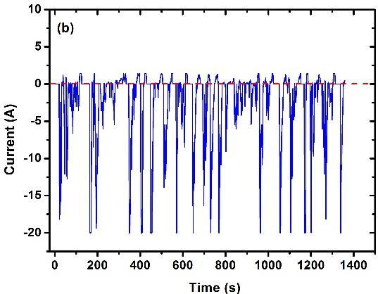
26 Technical Limitations of FCs 2. Durability and Reliability: 1. The performance of every FC gradually degrades with time due to a variety of phenomena 2. Automotive FC must withstand load cycling and freeze-thaw environmental swings with an acceptable level of degradation from the beginning-of-life (BOL) performance over a life time of 5500 h (~ 165,000 miles at 30 mph) 3. A stationary FC must withstand over h of steady operation under vastly changing external temperature conditions FCs should not be seen as a panacea for every power generating applns in the world


27 Direct H 2 Fuel Cell 50,000 h, 100 % RH 5,500 h, 30 % RH
28 Technical Limitations of FCs 3. System Power Density and Specific Power: US DOE year 2010 targets for system power density and specific power are: W/kg and 650 W/L for automotive (50 KW) applications W/kg and 170 W/L for auxiliary (5 to 10 kw peak) applications W/kg and 100 W/L for portable (mw to 50 W) applications. FCs should not be seen as a panacea for every power generating applns in the world
29 Technical Limitations of FCs 4. Fuel: Fuel Storage, Generation and Delivery technologies must be advanced if pure hydrogen is to be used. 5. Performance: 1. Desired performance and longevity of system components must be achieved. 2. New hardware (e.g., high volume blowers and efficient power conditioners) must be developed to suit the needs of the FC power systems 6. Controls: Sensors and online control systems for FC systems are needed for transient operation, where performance instability can become a major issue, FCs should not be seen as a panacea for every power generating applns in the world

30 The key Triad Durability FC Applns. Performance Cost
 FCS cost ($30/kW) Humidification (No) 10 8 6 4 2 0 Frozen temp (-40 C Coolant temp (120 C) S Tolerance (1ppm) Reliability Performance Cost Specific Power (500W/kg")
31 Barriers on the way to FCVs Pt Loading (0.2 mg Pt/cm 2 ) C.D. (1.5 A/cm 2 ) FCS cost ($30/kW) Humidification (No) Frozen temp (-40 C Coolant temp (120 C) S Tolerance (1ppm) Reliability Performance Cost Specific Power (500W/kg FCS) Operating h (5500 h V Cell Degradation (3mV/h) ) MTBF (1000h) Start/Stop Cycles (30k) Current Next Step Target
32 Electromotive Force (EMF) If E is the voltage of the fuel cell, then the electrical work done moving this charge round the circuit is Electrical work done = charge voltage = 2F*E joules If the system is reversible (or has no losses), then this electrical work done will be equal to the Gibbs free energy released Dgf. So Dgf = 2F *E Thus E = Dgf /2F This fundamental equation gives the EMF or reversible OCV of the H2 FC. 32
33 Problem Calculate the Open Circuit Voltage values of a Hydrogen fuel cell operating at 25 and also 800 o C. 33
34 Efficiency A more well-known example of an efficiency limit is that for heat engines such as steam and gas turbines. If the maximum temperature of the heat engine is T1, and the heated fluid is released at temperature T2, then Carnot showed that the maximum efficiency possible is Carnot limit = (T1 T2)/T1 As an example, for a steam turbine operating at 400 C (675 K), with the water exhausted through a condenser at 50 C (325 K), the Carnot efficiency limit is ( )/675 = 0.52 = 52% 34
35 Effect of Pressure and Gas Concn. We noted that the Gibbs free energy changes in a chemical reaction vary with temperature. Equally important, though more complex, are the changes in Gibbs free energy with reactant pressure and concentration. A general reaction such as j moles of J react with k moles of K to produce m moles of M. 35
36 Effect of Pressure and Gas Concn. Each of the reactants, and the products, has an associated activity. This activity is designated by a, aj, and ak being the activity of the reactants, and am the activity of the product. It is beyond the scope of this course to give a thorough description of activity. However, in the case of gases behaving as ideal gases, it can be shown that where P is the pressure or partial pressure of the gas and P 0 is standard pressure, 0.1 MPa. 36
37 Effect of Pressure and Gas Concn. is the change in molar Gibbs free energy of formation at standard pressure For the FC reaction H 2 + ½ O 2 H 2 O If the activity of the reactants increases, becomes more negative, that is, more energy is released. 37
38 Effect of Pressure and Gas Concn. To see how this equation affects voltage, the equation in the previous page becomes, where E 0 is the EMF at standard pressure This is Nernst equation The equation shows precisely how raising the activity of the reactants increases the voltage. The EMF calculated is Nernst voltage and is the reversible cell voltage that would exist at a given temperature and pressure. 38
39 Effect of Pressure and Gas Concn. In a mixture of gases, the total pressure is the sum of all the partial pressures of the components of the mixture. For example, in air at 0.1MPa, the partial pressures are as shown Gas Partial pressure (Mpa) Nitrogen Oxygen Argon Others (including CO2) Total
40 Effect of Pressure and Gas Concn. At high temperature (e.g. in a SOFC at 1000 C) we can assume that the steam behaves as an ideal gas, and so The Nernst Equation is If all the pressures are given in bar, then P0 = 1 40
41 Effect of Pressure and Gas Concn. H 2 gas might be part of a mixture of H2 and CO2 from a fuel reformer, together with product steam. The O 2 will nearly always be part of air. It is also often the case that the pressure on both the cathode and the anode is approximately the same this simplifies the design. If this system pressure is P, then where α, β, and δ are constants depending on the molar masses and concentrations of H2, O2, and H2O. 41
42 Problem Calculate the Open Circuit Voltage value of a Hydrogen fuel cell operating at 205 o C with pure oxygen and Hydrogen containing 5 % CO2. System pressure is 1 atm. 42
43 Hydrogen partial pressure Hydrogen can either be supplied pure or as part of a mixture. If we isolate the pressure of hydrogen term So, if the hydrogen partial pressure changes, say, from P1 to P2 bar, with P O2 and P H2O unchanged, then the voltage will change by 43
44 Problem Calculate the increase in Open Circuit Voltage value of a Hydrogen fuel cell operating at 90 o C, when the Hydrogen pressure is increased from 1 to 2 atm (with pure oxygen, pressure is 1 atm). 44
45 Hydrogen partial pressure The use of H2 mixed with CO2 occurs particularly in phosphoric acid fuel cells, operating at about 200 C. Substituting the values for R, T, and F gives As an example, changing from pure hydrogen to 50 % H 2 /CO 2 mixture will reduce the voltage by 0.015V per cell. 45
46 System pressure The Nernst equation (page 34) shows that the EMF of a fuel cell is increased by the system pressure according to the term So, if the pressure changes from P1 to P2 there will be a change of voltage For an SOFC operating at 1000 C, this would give 46
47 Problem Calculate the increase in Open Circuit Voltage value of a Hydrogen fuel cell operating at 90 o C, when the Hydrogen and Air pressure are increased from 1 to 3 atm. 47
48 Air or Oxygen A similar effect occurs when studying the change from air to oxygen. This effectively changes β in Nernst equation (page 34) from 0.21 to 1.0. Isolating β gives For the change in β from 0.21 to 1.0, with all other factors remaining constant, For a proton exchange membrane (PEM) fuel cell at 80 C this would give V = 0.012V 48
49 Problem Calculate the Open Circuit Voltage value of a Hydrogen fuel cell operating at 50 o C with pure Hydrogen and air. System pressure is 2 atm. 49
50 Operational Voltage Theoretical value of the OCV of a H 2 FC is given by the formula This gives a value of about 1.2V for a cell operating below 100 C. However, when a fuel cell is made and put to use, it is found that the voltage is less than this, often considerably less. Figure in next page shows the performance of a typical FC operating at ~ 70 C, at normal air pressure. 50
51 Low Temp FC Performance 51
52 Low Temp FC Performance The key points to notice about this graph of the cell voltage against current density are as follows: Even the open circuit voltage is less than the theoretical value. There is a rapid initial fall in voltage. The voltage then falls less rapidly, and more linearly. There is sometimes a higher current density at which the voltage falls rapidly. 52
53 High Temp FC Performance If a fuel cell is operated at higher temperatures, the shape of the voltage/current density graph changes. As we have seen earlier, the reversible no loss voltage falls. However, the initial fall in voltage as current is drawn from the cell is markedly less. Figure in next page shows the situation for a typical SOFC operating at about 800 C. 53
54 High Temp FC Performance 54
55 High Temp FC Performance The key points here are as follows: The open circuit voltage is equal to or only a little less than the theoretical value. The initial fall in voltage is very small, and the graph is more linear. There may be a higher current density at which the voltage falls rapidly, as with lowertemperature cells. 55
56 Voltage Loss The graphs of Figures show the difference between the expected voltage from a fuel cell operating ideally (reversibly) and the actual voltage. Overvoltage or overpotential is the term often used by electrochemists. This is because it is a voltage superimposed over the reversible or ideal voltage. Polarisation is another term much used by some electrochemists and others. 56
57 Polarization Curve for FC 57
58 Causes of Voltage Drop The characteristic shape of the voltage/current density graphs of Figures results from four major irreversibilities. 1. Activation losses. 2. Fuel crossover and internal currents. 3. Ohmic losses. 4. Mass transport or concentration losses. 58
59 Tafel Equation The constant A is higher for an electrochemical reaction that is slow. The constant i 0 is higher if the reaction is faster. The current density i 0 can be considered as the current density at which the overvoltage begins to move from zero. It is important to remember that the Tafel equation only holds true when i > i 0. i 0 is usually called the exchange current density 59
60 Tafel Equation constant, A For a H 2 fuel cell with two electrons transferred per mole, the constant A The constant α is called the charge transfer coefficient Its value depends on the reaction involved and the material the electrode is made from. For H 2 electrode, it is ~0.5 for a great variety of electrode materials. For O 2 electrode, it is between ~0.1 & 0.5 in most circumstances. 60
61 Exchange Current Density, i o At zero current, the reaction is taking place all the time, but the reverse reaction is also taking place at the same rate. There is an equilibrium expressed as Thus, there is a continual backwards and forwards flow of electrons from and to the electrolyte. This current density is i 0, the exchange current density. 61
62 Operating Voltage Imagine a fuel cell that has no losses at all except for this activation overvoltage on one electrode. Its voltage would then be given by the equation where E is the reversible OCV. If we plot graphs of this equation using values of i 0 of 0.01, 1.0, and 100 macm 2, using a typical value for A of 0.06 V, we get the curves shown in next page. 62
63 Problem Calculate the Activation Polarization value at an operating current density of 50 ma.cm -2 (25 deg C for a H2/air fuel cell with an exchange current density value of 0.1 ma.cm -2 and a value of
64 Problem Calculate the cell voltage at an operating current density of 50 ma.cm -2 (25 deg C) for a H2/air fuel cell at 2 atm, with an exchange current density value of 0.1 ma.cm -2 and a value of
65 Reducing Activation Loss A crucial factor in improving fuel cell performance is, to increase the value of i 0, especially at the cathode. This can be done in the following ways: Raising the cell temperature Using more effective catalysts Increasing the roughness of the electrodes Increasing reactant concentration, for example, using pure O2 instead of air Increasing the pressure 65
66 Polarization Curve for FC 66
67 Polarization Curve for FC 67
68 Ohmic Losses The losses due to the electrical resistance of the electrodes, and the resistance to the flow of ions in the electrolyte, are the simplest to understand and to model. The size of the voltage drop is simply proportional to the current, that is, V = IR In most fuel cells the resistance is mainly caused by the electrolyte, though the cell interconnects or bipolar plates can also be important. 68
69 Cell Resistance 69
70 Problem Calculate the Ohmic Polarization loss values at various operating current densities of 200, 500, 800, 1000 ma.cm -2 for fuel cells with MEAs showing and 0.1 Ohm. cm 2 70
71 Mass Transport or Concentration Losses If O 2 at the cathode of a FC is supplied in the form of air, then it is self-evident that during FC operation there will be a slight reduction in the concentration of the oxygen in the region of the electrode, as the O 2 is extracted. The extent of this change in concentration will depend on the current being taken from the fuel cell, and on physical factors relating to how well the air around the cathode can circulate, and how quickly the oxygen can be replenished. This change in concentration will cause a 71
72 Mass Transport or Concentration Losses The reduction in gas pressure will result in a reduction in voltage. These give the change in OCV caused by a change in pressure of reactants. There are also problems with lower-temperature cells, and those supplied with hydrogen mixed with other gases such as carbon dioxide for the fuel. 72
73 Mass Transport or Concentration Losses The mass transport or concentration overvoltage is particularly important in cases where the hydrogen is supplied from some kind of reformer, as there might be a difficulty in increasing the rate of supply of hydrogen quickly to respond to demand. Another important case is at the air cathode, if the air supply is not well circulated. A particular problem is that the nitrogen that is left behind after the oxygen is consumed can cause a mass transport problem at high currents it effectively blocks the oxygen supply. In PEMFCs, the removal of water can also be a cause of mass transport or concentration overvoltage. 73
74 What happens with O2 to Air? 74
75 Operational Voltage of single cell OC Voltage (h ct ) a + (h ct ) c Actual voltage IR loss (h c ) a + (h c ) c Useful Energy Blue: Useful energy (Electricity) Red: Waste (Heat) E = E ocv ((h ct ) a + (h ct ) c ) ((h c ) a + (h c ) c ) IR
76 PEM Fuel Cell Current interrupt test for a low-temperature, ambient pressure, hydrogen fuel cell. The ohmic and activation voltage drops are similar. (Time scale 0.2 s/div, i = 100mAcm 2.) 76
77 Direct Methanol Fuel Cell Current interrupt test shows a large activation overvoltage at both electrodes. As a result, the activation overvoltage is much greater than the ohmic, which is barely discernible. (Time scale 2 s/div. i = 10mAcm 2.) 77
78 SOFC Current interrupt test for a small solid oxide fuel cell working at ~ 700 C. The large immediate rise in voltage shows that most of the voltage drop is caused by ohmic losses.(time scale 0.02 s/div. I = 100mAcm 2.) 78
79 Water Production In a hydrogen-fed fuel cell, water is produced at the rate of one mole for every two electrons. The molecular mass of water is kg mole 1, so this becomes as a rough guide, 1 kwh of fuel cell generated electricity produces about 1 pint or 0.5 L of water 79
80 Problem Calculate the amount of water produced for a 1-kW fuel cell operating for 1 h, at a cell voltage of 0.7 V. Calculate the amount of water produced for a 100 kw fuel cell operating for 1 min, at a cell voltage of 0.6 V. 80
81 O 2, Air and H 2 Flow Rates = 3.5 P e /Vc SCCM = 16.7 P e /Vc SCCM with stoich = 1 In other words, 3.5 SCCM of O 2 or 16.7 SCCM of air and 7 SCCM of H 2 would produce 1 A current 81
82 Useful numbers To produce 1 A current with 100 % utilization (or stoichiometry of 1): Flow rate of H2 Gas: 7 cc per min Flow rate of O2 Gas: 3.5 cc per min Flow rate of air: cc per min 82
83 Problem If there is 10 m 3 of hydrogen in compressed bottle, how long (hours) can it last for a 2 kw fuel cell stack operating at 0.5 V per cell (capable of generating 1 A/cm 2 having 200 cm 2 area) with fuel utilization of 90 %? H2 required per hour per A with 90 % utilization = 7*60/0.9 For 2 kw 7*60*2000/0.5/0.9 = cc per h Total hours: 10,000,000 cc / = 5.36 h 83
84 Problem If there is 10 m 3 of hydrogen in compressed bottle, how long (hours) can it last for a 2 kw fuel cell stack operating at 0.5 V per cell (capable of generating 1 A/cm 2 having 200 cm 2 area) with fuel utilization of 90 %? H2 required per hour per A with 90 % utilization = 7*60/0.9 For 2 kw 7*60*2000/0.5/0.9 = cc per h Total hours: 10,000,000 cc / = 5.36 h 84
85 Heat Produced The cases in which water finally ends in liquid form are so few and so we will restrict ourselves to the vapor case. For a stack of n cells at current I, the heat generated is thus In terms of electrical power, this becomes 85
86 Problem Calculate the heat produced in Joules/sec for a 1kW fuel cell stack operating at 0.6 V/cell if the product is water vapor. Also calculate the heat produced if the FC stack operates 0.5 V/cell. Which operating condition is better and why? 86

87 Problem Calculate the heat produced for a 3 MW solid oxide fuel cell stack operating at 0.5 V/cell. 87
88 Fuel Cell Performance Variables The performance of fuel cells is affected by Operating variables Current density Temperature Pressure Gas composition Reactant utilization Cell design and Other factors (impurities, cell life) These variables influence the ideal cell potential and the magnitude of the voltage losses 88


89 PROGRESS IN FUEL CELL TECHNOLOGY Blast from the past. A picture of the original UTC fuel cells used in a number of NASA missions
Module 9: Energy Storage Lecture 34: Fuel Cell
 Module 9: Energy Storage Lecture 34: Fuel Cell In this lecture the energy storage (fuel cell) is presented. The following topics are covered in this lecture: Fuel cell Issues in fuel cell Hydrogen fuel
Advanced Analytical Chemistry Lecture 10. Chem 4631
 Advanced Analytical Chemistry Lecture 10 Chem 4631 What is a fuel cell? An electro-chemical energy conversion device A factory that takes fuel as input and produces electricity as output. O 2 (g) H 2 (g)
FUEL CELLS: Types. Electrolysis setup
 FUEL CELLS: Types History of the technology The fuel cell concept was first demonstrated by William R. Grove, a British physicist, in 1839. The cell he demonstrated was very simple, probably resembling
Fuel Cell Technology
 Fuel Cell Technology 1. Technology overview 2. Fuel cell performance 3. Fuel cell systems 4. Sample calculations 5. Experiment using PEM cell Goal: To provide a better understanding of the fuel cell technology,
Fuel Cells Introduction Fuel Cell Basics
 Fuel Cells Introduction Did you know that the appliances, lights, and heating and cooling systems of our homes requiring electricity to operate consume approximately three times the energy at the power
Trends in the Use of Fuel
 Hydrogen Fuel Cell Trends in the Use of Fuel Wood Coal Oil Natural Gas Hydrogen Percentage of hydrogen content in fuel 19 th century: steam engine 20 th century: internal combustion engine 21 st century:
CH2356 Energy Engineering Fuel Cell. Dr. M. Subramanian
 CH2356 Energy Engineering Fuel Cell Dr. M. Subramanian Associate Professor Department of Chemical Engineering Sri Sivasubramaniya Nadar College of Engineering Kalavakkam 603 110, Kanchipuram(Dist) Tamil
Introduction Fuel Cells
 Introduction Fuel Cells Fuel cell applications PEMFC PowerCell AB, S2 PEMFC, 5-25 kw Toyota Mirai a Fuel Cell Car A look inside The hydrogen tank 1. Inside Layer of polymer closest to the H2 gas 2. Intermediate
AC : DESIGN OF AN EXPERIMENTAL POWER SOURCE USING HYDROGEN FUEL CELLS
 AC 2007-2870: DESIGN OF AN EXPERIMENTAL POWER SOURCE USING HYDROGEN FUEL CELLS Esther Ososanya, University of the District of Columbia Samuel Lakeou, University of the District of Columbia Abiyu Negede,
Fuel Cell Technology
 Fuel Cell Technology TFRF05 Docent Jinliang Yuan October 30, 2008 Department of Energy Sciences, Lund University, Sweden Lectures: Docent Jinliang Yuan Home Works/Design Tasks: Dr. Jinliang Yuan Emails:
HYDROGEN FUEL CELL TECHNOLOGY
 HYDROGEN FUEL CELL TECHNOLOGY Vikash, Vipin Yadav, Vipin Badgaiyan Dronacharya College of Engineering, Gurgaon Abstract: - Whereas the 19th century was the century of the steam engine and the 20th century
Outline. Determining Equivalence Factors II. Fuel Cell Stack. Fuel Cell Basic Principles. Overview of Different Fuel Cell Technologies
 Vehicle Propulsion Systems Lecture 8 Fuel Cell Vehicles Lars Eriksson Professor Vehicular Systems Linköping University May 3, 8 / 4 / 4 Deterministic Dynamic Programming Basic algorithm N J(x ) = g N (x
Sustainable Energy Science and Engineering Center. Fuel Cell Systems and Hydrogen Production
 Fuel Cell Systems and Hydrogen Production Fuel Cell Type < 5kW 5-250kW < 100W 250kW 250kW - MW 2kW - MW Electrochemical Reactions 11 Efficiency Efficiency Source: Hazem Tawfik, Sept 2003 Pressure Effects
Fuel cells, myths and facts. PhD candidate Ole-Erich Haas
 Fuel cells, myths and facts PhD candidate Ole-Erich aas 1 Outline Fuel cell, history and general principle Fuel cell types and chemical systems PEM fuel cells for transport sector Polymer membranes Electrodes
Current Status of Fuel Cell Technology
 Hydrogen, Carbon-Free-Fuel Democratizing the Energy Current Status of Fuel Cell Technology By Dr.-Ing. Syed Mushahid Hussain Hashmi Professor / Chairman Dept. of Automotive & Marine Engineering, NED University
Designing and Building Fuel Cells
 Designing and Building Fuel Cells Colleen Spiegel Me Grauv Hill NewYork Chicago San Francisco Lisbon London Madrid Mexico City Milan New Delhi San Juan Seoul Singapore Sydney Toronto Foreword xii Chapter
Direct Energy Conversion: Fuel Cells
 Direct Energy Conversion: Fuel Cells References: Direct Energy Conversion by Stanley W. Angrist, Allyn and Beacon, 982. Fuel Cell Systems, Explained by James Larminie and Andrew Dicks, Wiley, 2003. Fuel
ENVIRONMENT-FRIENDLY HYDROGEN GAS AS FUEL IN FUEL CELL AND ITS CHALLENGES
 ENVIRONMENT-FRIENDLY HYDROGEN GAS AS FUEL IN FUEL CELL AND ITS CHALLENGES Hydrogen is the simplest and lightest element. Storage is one of the greatest problems for hydrogen. It leaks very easily from
MICRO FUEL CELLS for MOBILE POWER Thermal Management in Fuel Cells
 Thermal Management in Fuel Cells Jennifer Brantley Mechanical Engineer UltraCell Corporation 2/29/08 2/29/08 MEPTEC Thermal Symposium Session 4: Green 1 Agenda What is a Fuel Cell? Why Fuel Cells? Types
Alternatives to Alternative Energy - FUEL CELLS. C.J. Kobus Oakland University
 Alternatives to Alternative Energy - FUEL CELLS C.J. Kobus Oakland University Take Home Lesson Fuel cells can help us generate cleaner power from conventional sources more efficiently and can be conveniently
Fuel Cell Science & Technology
 446.671671 Fuel Cell Science & Technology Instructor: Suk Won Cha Course Introduction Office: 301-1417, 1417, Phone: 880-1700, Email: swcha@snu.ac.kr, Office Hours: A/O TA: Young Seok Ji Office: 314-311,
Figure 8: Typical Process Flow Diagram Showing Major Components of Direct Hydrogen PEFC System. Lecture No.8 Page 1
 PEFC Systems PEFC stacks require tight control of fuel and air feed quality, humidity level, and temperature for sustained high-performance operation. To provide this, PEFC stacks must be incorporated
Fuel Cells 101. Hydrogen Fuel Cell Educational Outreach Workshop Presented by David Cooke October 21 st, 2013
 Fuel Cells 101 Hydrogen Fuel Cell Educational Outreach Workshop Presented by David Cooke October 21 st, 2013 1 Why are hydrogen and fuel cells important? Hydrogen and fuel cells are technology solutions
Preliminary evaluation of fuel cells
 TR Preliminary evaluation of fuel cells Nils Arild Ringheim December 2000 TECHNICAL REPORT Energy Research SINTEF Energy Research Address: NO-7465 Trondheim, NORWAY Reception: Sem Sælands vei 11 Telephone:
New Energy Conservation Technologies
 Queensland University of Technology & University of Queensland Jan 2004 New Energy Conservation Technologies By Julian Dinsdale Executive Chairman, Ceramic Fuel Cells Limited ABSTRACT During the next one
Towards the development of low cost non-platinum based catalysts for catalytic water splitting
 Towards the development of low cost non-platinum based catalysts for catalytic water splitting Prospects of reducing greenhouse emission by hydrogen powered energy technologies Dr. Usman Ali Rana What
An experimental study of kit fuel cell car to supply power
 An experimental study of kit fuel cell car to supply power Mustafa I. Fadhel Faculty of Engineering and Technology, Multimedia University, Jalan Ayer Keroh Lama, 75450, Melaka, Malaysia. mustafa.i.fadhel@mmu.edu.my
GENERAL CLASSIFICATION
 GENERAL CLASSIFICATION M. OLIVIER marjorie.olivier@fpms.ac.be 19/05/2008 GENERAL CLASSIFICATION Type Electrolyte PEMFC DMFC DEFC PAFC AFC MCFC SOFC Proton exchange membrane fuel cell Direct methanol fuel
FUEL CELLS ALEJANDRO AVENDAO
 FUEL CELLS ALEJANDRO AVENDAO 1 1) INTRODUCTION 3 2) BACKGROUND 3 Fuel Cell Basics 3 Fuel Cell types 4 A. Proton Exchange Membrane Fuel Cells (PEMFC) 4 B. Direct Methanol Fuel Cells (DMFC) 5 C. Phosphoric
MIE 517 Final Celebration of Learning Wednesday, April 19, 2017, 2-4:30pm
 MIE 517 Final Celebration of Learning Wednesday, April 19, 2017, 2-4:30pm Instructions: Answer all questions and show all work for which you wish to receive credit in the answer booklets. You may use one
Fuel Cell Science & Technology
 446.671671 Fuel Cell Science & Technology Instructor: Suk Won Cha Course Introduction Office: 301-1417, 1417, Phone: 880-1700, Email: swcha@snu.ac.kr, Office Hours: A/O TA: Sanghoon Ji Office: 314-311,
Alejandro Avendaño Friday April 21, 2006
 FUEL CELLS AND DISTRIBUTED GENERATION Alejandro Avendaño Friday April 21, 2006 Introduction Distributed Generation The Electric Power Research Institute (EPRI) defines distributed generation as the integrated
Prof. Mario L. Ferrari
 Sustainable Energy Mod.1: Fuel Cells & Distributed Generation Systems Dr. Ing. Mario L. Ferrari Thermochemical Power Group (TPG) - DiMSET University of Genoa, Italy Lesson IV: fuel cells (PEFC or PEM)
FMI ENERGY CONFERENCE. Orlando September 2008
 FMI ENERGY CONFERENCE Orlando September 2008 FUEL CELL ORIGINS Sir William Grove invented the fuel cell in 1839 Demonstrated that reaction was reversible Fuel cell term introduced by Ludwig Mond and Charles
Use of Renewable Energy Resources
 Use of Renewable Energy Resources Lalina 1 1 Department of Electronics &Communication Engineering, Ganga Institute of Technology and Management, Kablana, Jhajjar, Haryana, India Absract: The electricity
Fuel Cell Technology: A Review
 Fuel Cell Technology: A Review Omkar Yarguddi 1, Dr. Anjali A. Dharme 2 Senior Undergraduate student, Dept. Of Electrical Engg, College of Engg, Pune, Maharashtra, India 1 Associate Professor, Dept. Of
3- PHOSPHORIC ACID FUEL CELLS
 3- PHOSPHORIC ACID FUEL CELLS (PAFCs) The phosphoric acid fuel cell (PAFC) was the first fuel cell technology to be commercialized. The number of units built exceeds any other fuel cell technology, with
Fuel Cell Systems: an Introduction for the Engineer (and others)
") Fuel Cell Systems: an Introduction for the Engineer (and others) Professor Donald J. Chmielewski Center for Electrochemical Science and Engineering Illinois Institute of Technology Presented to the E 3
Fuel Cell Systems: an Introduction for the Engineer (and others) Professor Donald J. Chmielewski Center for Electrochemical Science and Engineering Illinois Institute of Technology Presented to the E 3
By janaka. Copyrights HIMT
 By janaka Copyrights HIMT 2016 1 In container trade alone the equivalent of 125 million twenty-foot containers being shipped worldwide. It is these quantities that make shipping such a significant contributor
HOW IT WORKS w w w. f u e l c e l l p a r t n e r s h i p. o r g
 HOW IT WORKS w w w. f u e l c e l l p a r t n e r s h i p. o r g FUEL CELL ENERGY POWERS THE CAR! Electrical Current ELECTRONS The movement of electrons generates electricity to power the motor. OXYGEN
Fuel Cell Systems: an Introduction for the Chemical Engineer
 Fuel Cell Systems: an Introduction for the Chemical Engineer Professor Donald J. Chmielewski Center for Electrochemical Science and Engineering Illinois Institute of Technology Presented to the Chicago
Proceedings of the 14th International Middle East Power Systems Conference (MEPCON 10), Cairo University, Egypt, December 19-21, 2010, Paper ID 217.
, Cairo University, Egypt, December 19-21, 2010, Paper ID 217.") Proceedings of the 14th International Middle East Power Systems Conference (MEPCON 10), Cairo University, Egypt, December 19-21, 2010, Paper ID 217. Modeling and Analysis of a PEM Fuel cell for Electrical
Proceedings of the 14th International Middle East Power Systems Conference (MEPCON 10), Cairo University, Egypt, December 19-21, 2010, Paper ID 217. Modeling and Analysis of a PEM Fuel cell for Electrical
Evaluation of Solid Oxide Fuel Cells Operating on Hydrogen Sulfide Contaminated Fuel
 Evaluation of Solid Oxide Fuel Cells Operating on Hydrogen Sulfide Contaminated Fuel by: Abdolkarim Sheikhansari Supervisors: Dr. Simon Blakey Dr. Jonathan Paragreen A thesis submitted in partial fulfilment
Jason C. Ganley. Howard University Department of Chemical Engineering Washington, DC
 Intermediate Temperature Direct Ammonia Fuel Cells Jason C. Ganley Howard University Department of Chemical Engineering Washington, DC 1 Ammonia for Fuel Cells CH4 103 (1.5 H2)! Very mild enthalpy of reforming!
Analysis of individual PEM fuel cell operating parameters for design of optimal measurement and control instrumentation. Davor Živko 1, Vedran Bilas 2
 Analysis of individual PEM fuel cell operating parameters for design of optimal measurement and control instrumentation Davor Živko 1, Vedran Bilas 1 Koncar Electrical Engineering Institute, Fallerovo
Electrochemical cells use spontaneous redox reactions to convert chemical energy to electrical energy.
 ELECTROLYSIS: -the process of supplying electrical energy to a molten ionic compound or a solution containing ions so as to produce a chemical change (causing a non-spontaneous chemical reaction to occur).
Appendix A: Parameters that Used to Model PEM Fuel Cells
 Appendix A: Parameters that Used to Model PEM Fuel Cells Name Value Description L 0.06[m] Cell 1ength H_ch 1e-3[m] Channel height W_ch 9.474e-3[m] Channel width W_rib 9.0932e-3[m] Rib width H_gdl 640e-6[m]
A Parametric Study of Stack Performance for a 4.8kW PEM Fuel Cell Stack. A thesis presented to. the faculty of
 A Parametric Study of Stack Performance for a 4.8kW PEM Fuel Cell Stack A thesis presented to the faculty of the Russ College of Engineering and Technology of Ohio University In partial fulfillment of
DYNAMIC SIMULATION OF A PROTON EXCHANGE MEMBRANE FUEL CELL SYSTEM FOR AUTOMOTIVE APPLICATIONS
 DYNAMIC SIMULATION OF A PROTON EXCHANGE MEMBRANE FUEL CELL SYSTEM FOR AUTOMOTIVE APPLICATIONS R. A. Rabbani 1 and M. Rokni 2 1. Technical University of Denmark, Kgs. Lyngby, Denmark; email: raar@mek.dtu.dk
Energy from Renewables: Envisioning a Brighter Future. Fuel Cells Charles Vesely
 Energy from Renewables: Envisioning a Brighter Future Fuel Cells Charles Vesely Who are we? Cummins Power Generation (AKA Onan) World Headquarters, Central Engineering, and Manufacturing for the Americas
A FEASIBILITY STUDY OF FUEL CELL COGENERATION IN INDUSTRY
 A FEASIBILITY STUDY OF FUEL CELL COGENERATION IN INDUSTRY Scott B. Phelps and J. Kelly Kissock Department of Mechanical Engineering University of Dayton Dayton, Ohio ABSTRACT Up until now, most of the
Fuel Cell - What is it and what are the benefits? Crina S. ILEA, Energy Lab, Bergen
 Fuel Cell - What is it and what are the benefits? Crina S. ILEA, 10.01.2017 Energy Lab, Bergen CMI Founded in 1988 Two departments: Parts & Services Research & Development Prototype development from idea
I. INTRODUCTION. II. OBJECTIVE OF THE EXPERIMENT. III. THEORY
 I. INTRODUCTION. Chemical pollution is a serious problem that demands the attention of the scientific community in the early 21 st century. The consequences of pollution are numerous: heating of the atmosphere
Energy From Electron Transfer. Chemistry in Context
 Energy From Electron Transfer Chemistry in Context Energy Types Batteries Hybrid Cars (Electrical) H 2 (and Other) Fuel Cells Solar Fuel Cell Car Demo H 2 Fuel Cell Reactions Step 1: H 2 (g) 2H + (aq)
Wet Cells, Dry Cells, Fuel Cells
 page 2 page 3 Teacher's Notes Wet Cells, Dry Cells, Fuel Cells How the various electrochemical cells work Grades: 7-12 Duration: 33 mins Program Summary This video is an introductory program outlining
Brief Introduction to Fuel Cells, Hydrogen Production and Storage
 Brief Introduction to Fuel Cells, Hydrogen Production and Storage Production Outline Intermediate Conversion Electrolysis Jens Oluf Jensen Energy Reforming Microbial Thermal Transmission Storage Fuel cells
UNIT-I ELECTROCHEMISTRY PART-A
 UNIT-I ELECTROCHEMISTRY PART-A 1. What is electrochemistry? 2. What do you understand by electrode potential? 3. Define E.M.F of an electrochemical cell? 4. Define (a) Single electrode potential (b) Standard
A FUEL CELL AS A PETROL SUBSTITUTE; A FEASABILITY STUDY
 A FUEL CELL AS A PETROL SUBSTITUTE; A FEASABILITY STUDY SALAH I. AL-MOUSLY, member, IEEE, and ZIAD K. ALHAMDANI, member, ASA Faculty of Electronic Engineering, P.O. Box 38645, Libya ABSTRACT In the end
ESSENCE - International Journal for Environmental Rehabilitation and Conservation
 ESSENCE - International Journal for Environmental Rehabilitation and Conservation Volume VIII: No. 1 2017 [108 119] [ISSN 0975-6272] [www.essence-journal.com] Hydrogen Fuel Cell Saini, Richa Received:
BioGas and Fuel Cells BioGas 2020 Skandinavias Biogaskonferanse 2018, Fredrikstad, April Crina S. ILEA Contact:
 BioGas and Fuel Cells BioGas 2020 Skandinavias Biogaskonferanse 2018, Fredrikstad, 25-26 April 2018 Crina S. ILEA Contact: crina@prototech.no Christian Michelsen Institute (CMI) Founded in 1988 Two departments:
P21 WHITE PAPER FUNCTIONAL DESCRIPTION PREMION T FUEL CELL SYSTEM. Copyright 2006 P21 GmbH. All rights reserved.
 P21 WHITE PAPER FUNCTIONAL DESCRIPTION PREMION T FUEL CELL SYSTEM Copyright 2006 P21 GmbH. All rights reserved. No part of this publication may be reproduced or transmitted in any form or for any purpose
Integrated Electrochemical Thermal Ammonia Production Process
 Integrated Electrochemical Thermal Ammonia Production Process Junhua Jiang, Ted Aulich, Alexey Ignatchenko, and Chris Zygarlicke, Energy & Environmental Research Center (EERC) University of North Dakota
liquid catalyst in a solution gas catalyst in the gas phase
 Famous Catalysts As we discussed when examining the Arrhenius equation K= A exp (-Ea/RT) one important factor in the rate of reaction is the activation energy. The larger E a, the smaller k and the slower
Hydrogen and fuel cells: towards a sustainable energy future
 Hydrogen and fuel cells: towards a sustainable energy future Professor Peter P. Edwards Head of Inorganic Chemistry University of Oxford Co-ordinator UK Sustainable Hydrogen Energy Consortium UK representative
Accelerated Stress Tests in PEM Fuel Cells: What can we learn from it?
 Accelerated Stress Tests in PEM Fuel Cells: What can we learn from it? D.P. Wilkinson 1,3, W. Merida 2,3 1 st Workshop : Durability and Degradation Issues in PEM Electrolysis Cells and its Components Fraunhofer
Fuel Cell A Future Powerhouse Dr Sudhir Kumar, Chief Executive, Green Energy Solutions, Pune Fuel Cell History
 Fuel Cell A Future Powerhouse Dr Sudhir Kumar, Chief Executive, Green Energy Solutions, Pune Fuel Cell History The principle of the fuel cell was discovered by German scientist Christian Friedrich Schönbein
PEFC Technology Development
 PEFC Technology Development Göran Lindbergh, Björn Eriksson, Annika Carlson, Rakel Wreland Lindström, Carina Lagergren, KTH Fuel Cell 2015 Arlanda, December 3, 2015 Layout of presentation Introduction
Electronic circuit model for proton exchange membrane fuel cells
 Journal of Power Sources 142 (2005) 238 242 Short communication Electronic circuit model for proton exchange membrane fuel cells Dachuan Yu, S. Yuvarajan Electrical and Computer Engineering Department,
V.0 Fuel Cells Program Overview
 V.0 Fuel Cells Program Overview Introduction The Fuel Cells program supports research, development, and demonstration of fuel cell technologies for a variety of transportation, stationary, and portable
DISCLAIMER. Portions of this document may be illegible electronic image products. Images are produced from the best available original document.
 3 rn -I 0 ZLS TL-s DISCLAIMER Portions of this document may be illegible electronic image products. Images are produced from the best available original document. INDIRECT-FIRED GAS TURBINE DUAL FUEL CELL
MAE 214 FUEL CELL FUNDAMENTALS & TECHNOLOGY. Fuel Cell Introduction
 MAE 214 FUEL CELL FUNDAMENTALS & TECHNOLOGY Fuel Cell Introduction NFCRC DR. JACK BROUWER MAE 214 Lecture #1 Spring, 2005 Fuel Cell Introduction History Basic Operation Fuel Cell Stack Fuel Cell Types
ABB Automation & Power World: April 18-21, 2011 WRE Power Electronics for Hydrokinetics and Fuel Cells. ABB Inc. April 20, 2011 Slide 1
 ABB Automation & Power World: April 18-21, 2011 WRE-113-1 Power Electronics for Hydrokinetics and Fuel Cells ABB Inc. April 20, 2011 Slide 1 Content Power generation & the grid Introduction to Hydrokinetics
CHAPTER 3 MODELING OF SOLID OXIDE FUEL CELL GAS TURBINE HYBRID SYSTEM. Solid oxide fuel cells consists of a solid electrolyte (zirconia), which is a
, which is a") 84 CHAPTER 3 MODELING OF SOLID OXIDE FUEL CELL GAS TURBINE HYBRID SYSTEM A model is neither true nor false it is more or less useful - (Stafford Beer, 1985) 3.1 Solid Oxide Fuel Cell Solid oxide fuel cells
84 CHAPTER 3 MODELING OF SOLID OXIDE FUEL CELL GAS TURBINE HYBRID SYSTEM A model is neither true nor false it is more or less useful - (Stafford Beer, 1985) 3.1 Solid Oxide Fuel Cell Solid oxide fuel cells
Modeling of Fuel Cell Connected Distribution Generation System
 International Refereed Journal of Engineering and Science (IRJES) ISSN (Online) 39-83X, (Print) 39-8 Volume 4, Issue (November 05), PP. 6-69 Modeling of Fuel Cell Connected Distribution Generation System
Parametric Study of the Hydrogen Fuel Cell Electrochemical Model
 1 Parametric Study of the Hydrogen Fuel Cell Electrochemical Model EnePro Conference June 3rd, 29 Department of Process and Environmental Engineering 2 Background Hydrogen production for fuel cells by
A Comparison of Two Engines. Benefits of an Electric Motor
 Fuel Cells (http://www.stanford.edu/group/fuelcell/images/fuel%0cell%0components.jpg) Lecture prepared with the able assistance of Ritchie King, TA 1 A Comparison of Two Engines Internal-combustion engine
Fuel Cell Characteristics
 Fuel Cell Characteristics e - load depleted fuel and product gases out depleted oxidant and product gases out H 2 OH - O 2 H 2 O H 2 O H 2 H + O 2 H 2 O H 2 CO = O 2 CO 3 2 CO 2 H 2 O H 2 O 2 H 2 O O =
High Temperature Thermochemical Water Splitting for Mass Production of Hydrogen Fuel
 High Temperature Thermochemical Water Splitting for Mass Production of Hydrogen Fuel Dr. William A. Summers Program Manger, Energy Security Directorate June 11, 2009 Fifth International Hydrail Conference
Methanol Steam Reformer High Temperature PEM Fuel Cell System Analysis
 Annex 3 to EDA Comm N 12/027 Methanol Steam Reformer High Temperature PEM Fuel Cell System Analysis Andrej LOTRIČ (Mebius d.o.o., Na jami 3, SI-1000 Ljubljana, Slovenia) and Stanko HOČEVAR (Mebius d.o.o.,
FABSTRACT. Technical Overview of Fuel Cell Systems: How Computer Simulation is Used to Reduce Design Time
 W H I T E P A P E R - 1 2 0 FABSTRACT Fuel cells offer the means for the conversion of chemical energy in hydrogen rich fuels (fossil and renewable) directly to electricity without having to generate thermal
Advanced Fuel Cell Technology for Co-Production of Electric Power and Carboxylic Acids Using Coal-Derived Alcohols
 Advanced Fuel Cell Technology for Co-Production of Electric Power and Carboxylic Acids Using Coal-Derived Alcohols Advent of the practical coal-fired fuel cell John M. Pope, Ph.D. Chairman NDC Power Cheyenne,
EXERGY ANALYSIS OF A SOFC BASED COGENERATION SYSTEM FOR BUILDINGS
 EXERGY ANALYSIS OF A SOFC BASED COGENERATION SYSTEM FOR BUILDINGS Can Ozgur Colpan cocolpan@connect.carleton.ca Ibrahim Dincer, PhD Ibrahim.Dincer@uoit.ca Feridun Hamdullahpur, PhD Feridun_Hamdullahpur@carleton.ca
Applicability of Dimethylether to Solid Oxide Fuel Cells
 17 Nov. 2011, 7th Asian DME Conference Applicability of Dimethylether to Solid Oxide Fuel Cells ~ Reforming and Cell Performance in Anode Off-gas Recycle ~ Yohei Tanaka, Katsutoshi Sato, Akihiko Momma,
Fuel Cells in Energy Technology (9) Werner Schindler Department of Physics Nonequilibrium Chemical Physics TU München summer term 2013
 Werner Schindler Department of Physics Nonequilibrium Chemical Physics TU München summer term 2013") Fuel Cells in Energy Technology (9) Werner Schindler Department of Physics Nonequilibrium Chemical Physics TU München summer term 2013 - Source - Distribution - CO poisoning - Emissions (true zero, CO
Fuel Cells in Energy Technology (9) Werner Schindler Department of Physics Nonequilibrium Chemical Physics TU München summer term 2013 - Source - Distribution - CO poisoning - Emissions (true zero, CO
FUEL CELL. Yann Bultel. Grenoble Institute of Technology
 Yann Bultel Grenoble Institute of Technology October 2012 C O N T E N T S 1. PRINCIPLE OF OPERATION... 3 1.1. INTRODUCTION TO... 3 1.2. UNIT CELL PRINCIPLE... 4 1.3. STACK... 7 1.4. SYSTEM... 7 1.5. PERFORMANCE...
Durability studies of membrane electrode assemblies for high. temperature polymer electrolyte membrane fuel cells. Nolubabalo Hopelorant Fanapi
 Durability studies of membrane electrode assemblies for high temperature polymer electrolyte membrane fuel cells By Nolubabalo Hopelorant Fanapi A thesis submitted in fulfilment of the requirements for
Hydrogen production via catalytic water splitting. Prospects of reducing greenhouse emission by hydrogen powered energy technologies
 Hydrogen production via catalytic water splitting Prospects of reducing greenhouse emission by hydrogen powered energy technologies Increasing molecular weight Mass energy densities for various fuels Fuel
Chapter 2 Fuel Cells Operating and Structural Features of MCFCs and SOFCs
 Chapter 2 Fuel Cells Operating and Structural Features of MCFCs and SOFCs 2.1 Introduction The current movement toward environmentally friendlier and more efficient power production has caused an increased
A system model of proton exchange membrane fuel cell for the study of the water/thermal management
 A system model of proton exchange membrane fuel cell for the study of the water/thermal management 4 th U.S. KOREA NanoForum April 26, 27 Sangseok Yu Environment and Energy Research Division Korea Institute
THE ROLE OF THE HYDROGEN FUEL CELL IN PROVIDING CLEAN ENERGY OF THE FUTURE
 THE ROLE OF THE HYDROGEN FUEL CELL IN PROVIDING CLEAN ENERGY OF THE FUTURE ENVIRONMENTAL SUSTAINABILITY 1983 Brundtland Commission- Our Common Future 1987 Sustainable Development Development that meets
Electricity. Characteristic and efficiency of PEM fuel cell and PEM electrolyser Stationary currents. What you need:
 Stationary currents Electricity Characteristic and efficiency of PEM fuel cell and PEM electrolyser What you can learn about Electrolysis Electrode polarisation Decomposition voltage Galvanic elements
Features and Benefits of Hydrogen Powered Transit. Andrew A. Rezin, Ph.D., Director Midwest Hydrogen Center of Excellence
 Features and Benefits of Hydrogen Powered Transit Andrew A. Rezin, Ph.D., Director Midwest Hydrogen Center of Excellence FUELING OUR EVERYDAY LIFE 2 Current primary fuel sources: Methane (CH 4 ) + oxygen
System Level modelling of fuel cell driven electric vehicles. Master s thesis in Electric Engineering ALBERT CERDÁN CODINA
 System Level modelling of fuel cell driven electric vehicles Master s thesis in Electric Engineering ALBERT CERDÁN CODINA Elteknik Power Electronics Department CHALMERS UNIVERSITY OF TECHNOLOGY Gothenburg,
Electrolysis, electrode polarisation, decomposition voltage, galvanic elements, Faraday s law.
 Characteristics and efficiency of PEM fuel cell TEP Related Topics Electrolysis, electrode polarisation, decomposition voltage, galvanic elements, Faraday s law. Principle In a PEM electrolyser, the electrolyte
APPLICATIONS WITH PROTON EXCHANGE MEMBRANE (PEM) FUEL CELLS FOR A DEREGULATED MARKET PLACE
 FUEL CELLS FOR A DEREGULATED MARKET PLACE") APPLICATIONS WITH PROTON EXCHANGE MEMBRANE (PEM) FUEL CELLS FOR A DEREGULATED MARKET PLACE Bernd KOHLSTRUCK ALSTOM BALLARD GmbH ABSTRACT: The electric utility is in a period of rapid change. The deregulation
APPLICATIONS WITH PROTON EXCHANGE MEMBRANE (PEM) FUEL CELLS FOR A DEREGULATED MARKET PLACE Bernd KOHLSTRUCK ALSTOM BALLARD GmbH ABSTRACT: The electric utility is in a period of rapid change. The deregulation
NEW APPROACHES TO IMPROVE THE PERFORMANCE OF THE PEM BASED FUEL CELL POWER SYSTEMS. A Dissertation WOOJIN CHOI
 NEW APPROACHES TO IMPROVE THE PERFORMANCE OF THE PEM BASED FUEL CELL POWER SYSTEMS A Dissertation by WOOJIN CHOI Submitted to the Office of Graduate Studies of Texas A&M University in partial fulfillment
Introduction. 1.1 Hydrogen Fuel Cells Basic Principles
 1 Introduction 1.1 Hydrogen Fuel Cells Basic Principles The basic operation of the hydrogen fuel cell is extremely simple. The first demonstration of a fuel cell was by lawyer and scientist William Grove
The Role of Fuel Cells in a Sustainable Energy Economy
 The Role of Fuel Cells in a Sustainable Energy Economy Energy Futures Sustainable Development in Energy, February 16 th 2005 Nigel Brandon Shell Chair in Sustainable Development in Energy, Faculty of Engineering
PEMFC Lifetime and Durability an overview. Thessaloniki, September Frank de Bruijn
 PEMFC Lifetime and Durability an overview Thessaloniki, September 21 2011 Frank de Bruijn PEMFC in real life 2007 Passenger vehicle: 2,375 hrs operated on 1 stack Daimler in DoE programme 2011 City Bus
An Introduction to Fuel Cells and Related Transport Phenomena
 An Introduction to Fuel Cells and Related Transport Phenomena Matthew M. Mench, Chao-Yang Wang and Stefan T. Thynell Electrochemical Engine Center Department of Mechanical and Nuclear Engineering The Pennsylvania