Porous Pavement Flow Paths
|
|
|
- Juniper Wiggins
- 6 years ago
- Views:
Transcription

1 POROUS PAVEMENT MODELING Clear Creek Solutions, Inc., 2010 Porous pavement includes porous asphalt or concrete and grid/lattice systems (nonconcrete) and paving blocks. The use of any of these types of porous pavement requires that certain minimum standards and requirements are met related to subgrade, geotextile material, separation or bottom filter layer, base material, wearing layer, drainage conveyance, acceptance testing, and surface maintenance. WWHM4 has a new porous pavement element that incorporates both the standard basin element and the gravel trench bed element to represent porous pavement. The basin element input information represents the surface of the porous pavement and the gravel trench bed element information represents the subgrade. Porous Pavement Flow Paths Evaporation from pavement Rain on pavement Surface Runoff Infiltration through pavement Infiltration to gravel subgrade Underdrain Flow Infiltration to native soil 1
2 Porous pavement allows for infiltration through the pavement layer into a gravel/crushed rock subgrade with option of infiltration to the native soil and/or underdrain flow. Surface runoff only occurs when ponding occurs on the pavement surface following complete saturation of the subgrade and pavement layers. The porous pavement element should only be used when the following three conditions are met: 1. The infiltration rate of the porous pavement is greater than the peak rainfall rate. 2. The infiltration rate of the porous pavement is greater than the underlying native soil. 3. There is subgrade layer of crushed rock/gravel between the porous pavement and the native soil. For the purposes of this example we will model both conventional pavement and porous pavement side-by-side so to show the difference between the two. So let s get started. We will model a 5-acre parking lot adjacent to the Seattle-Tacoma (SeaTac) Airport. The first thing that we will do is to locate our project on the project map. 2

3 SeaTac Airport is located in King County, Washington. We click on the map to select the project location. Based on our project location WWHM4 selects the appropriate precipitation record and precipitation multiplication factor. We then have the option to fill in the Site Information boxes. For the Predevelopment scenario we select a standard land use basin. We have to decide the appropriate predevelopment land use for the project site. Because this project is located in Western Washington and has to meet Washington State Department of Ecology regulations, we select C soil, Forest vegetation, and Flat land slope (0-5%). The project site is 5 acres. Because we are modeling both conventional pavement and porous pavement side-by-side (normally you would just model one or the other), we have two basins with the same information. POC 1 represents the conventional pavement predevelopment runoff; POC 2 represents the porous pavement predevelopment runoff. Because the predevelopment land use is the same for both POC 1 and POC 2 the predevelopment runoff will be the same. This will not be true for the mitigated (post-development) runoff. 3

4 For the Mitigated scenario we will use the standard basin element to represent the conventional impervious pavement and the porous pavement element to represent the porous pavement. The conventional pavement will still need some form of mitigation for the extra runoff produced when the forest is removed and the 5-acre site paved. One mitigation option is to place a stormwater vault under the parking lot to collect the runoff and then discharge it at the predevelopment flow rate. That is what we will do in this example. 4
5 First we add the basin element, rename it Conventional Pavement, and assign 5 acres of Parking, Flat land use. 5
6 We add a vault element (naming it Conventional Vault ) and connect its outlet to POC 1. Now we can use Auto Vault to size the vault. 6

7 We set the adjustment level (amount of optimization) to its highest level (5) and then click Create Vault. Take a break while Auto Vault runs through its iterations and I will meet you on the far side after it has finished. 7

8 8
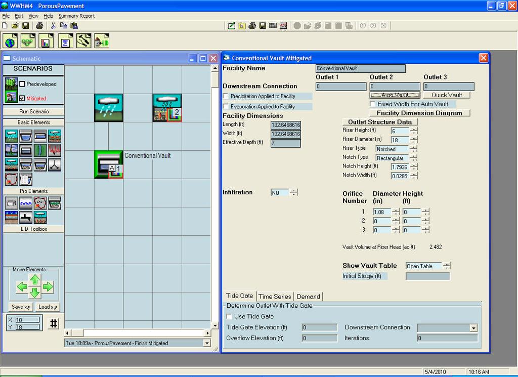
9 Auto Vault is finished. It gives us a conventional vault size of 133 feet long by 133 feet wide by 7 feet deep. Big vault. Now we will model the same 5-acre parking lot with porous pavement. We add the porous pavement element and designate it as POC 2. We now have to input the element information. 9
10 The first thing that we will do is to input the facility dimensions. The parking lot is 5 acres in size. We need to convert that area into an equivalent length and width. Five acres is 217,800 square feet and that can be represented by a rectangle with a length of 500 feet and width of feet. We will skip the effective total depth for the moment (but we will come back to it) and enter the bottom slope (0.01 ft/ft). 10
11 The next input is the layers for the porous pavement and subgrade. We can have up to three layers. The first layer is always the porous pavement. We input the thickness of the porous pavement layer (6 inches or 0.5 feet) and the porosity of the pavement. Consult the manufacturer for the porosity of their particular pavement. For the purpose of this example we will assume that the porous pavement porosity is 0.30 (30% void space). The next layer is the subgrade. Usually this layer consists of gravel or crushed rock. It can be as thick or thin as we think is appropriate. For this example we will assume that the subgrade layer consists of one foot of gravel with a porosity of 0.35 (0.35%). We still need to decide on how we want to handle native infiltration and the underdrain information. Let s first talk about native infiltration. At the project site the native soil is a C soil with poor drainage/infiltration. We need to talk to the local municipal permitting agency about whether or not we can include infiltration to the native soil in our porous pavement model. Most agencies are going to be skeptical about allowing any infiltration to a C native soil. However, they may be more agreeable to the idea if they think long-term instead of short-term. With traditional single event modeling the focus was always on the short-term benefits of infiltration. Only high infiltration rates are important when computing runoff from a short-term single storm event. However, with long-term continuous simulation modeling 11
12 (which is what we are doing here) even very low infiltration rates are significant. This is because the facility (pond, tank, vault, bioretention area, porous pavement subgrade, etc.) can drain to the native soil over weeks and months, instead of just hours and days. For our example, let s assume that the local municipal permitting agency allows a native soil infiltration rate of 0.01 inches per hour (that is about 1 inch per 4 days). In a month 8 inches of water can drain into the native soil. That is 8 feet of water per year. So, an infiltration rate of 0.01 inches per hour may be slow but it adds up over time and that is why we want to turn on infiltration (Infiltration = YES) and include it in the drainage calculations. We input a measured infiltration rate of 0.01 inches/hour. A reduction factor is also required. The reduction factor is multiplied by the measured infiltration rate to get the model s long-term infiltration rate (so don t leave it at zero or there won t be any longterm infiltration). The reduction factor is the same as 1/safety factor and accounts for the potential of long-term clogging of infiltration facilities. For an infiltration pond the Washington State Department of Ecology requires a safety factor of 4 (reduction factor of ¼ or 0.25). Currently there are no safety factor guidelines for porous pavement. I argue that the porous pavement safety factor should be 1 because opportunities for sediment to clog the subgrade/native soil interface are minimal at best. So we will use a reduction factor of 1 for this example. 12
13 There is a Size Pavement button below the Infiltration input that may have piqued your curiosity. For this example project we are not going to use it, but since we are here I might as well tell you how it works and when to use it. We give the user the option to route runoff from another element (that other element must be a lateral flow basin). That means that you can have some pervious area (like a lawn) or impervious area (like an impervious road surface) drain directly to the porous pavement element. If you have a target percent infiltrated (say, 100%) then by clicking on the Size Pavement button you will let WWHM4 determine how big the porous pavement area must be to achieve your target infiltration percentage. It doesn t make sense to use the Size Pavement option if the only area draining to the porous pavement is the porous pavement area itself. When there is a 1 to 1 ratio of the surface area to the infiltration area (as there is with the porous pavement element without any lateral flow connections) then the percent runoff infiltrated is only a function of the native infiltration rate and the storage in the pavement and subgrade layers plus whatever surface ponding is allowed (more on that below). Size doesn t matter. 13
14 Now let s talk about whether or not we want to include an underdrain. The underdrain has a diameter and a height above the subgrade/native soil interface (the bottom of the subgrade layer). You can have both an underdrain and native infiltration; in that situation most of the water will exit via the underdrain. So, because of that, it is usually best to have either an underdrain or native infiltration, but not both. The advantage of an underdrain is that it keeps the subgrade from becoming completely filled with water, especially if infiltration into the native soil is not allowed. The disadvantage is that the discharge from the underdrain must still meet flow control requirements. So, with an underdrain a stormwater mitigation facility (pond, tank, vault, etc.) will be needed for the porous pavement parking lot. The stormwater mitigation facility will be smaller than if we use conventional impervious pavement, but we are still going to need one to control the underdrain discharge. I generally recommend against using an underdrain unless there is absolutely no other way to handle the runoff. For this project we are going to model the parking lot without an underdrain. 14

15 The last piece of needed information is the depth of ponding allowed on the surface of the porous pavement. The question is: How deep does the water get on the surface of the pavement before runoff occurs? Typically there is going to be some ponding. We just have to tell the model how much. Without a curb to contain the water we are probably going to get only about an inch of water ponding on the surface of the pavement before it starts to runoff in one direction or another. Based on that idea we set the ponding depth to 0.1 feet. If you are not sure about the appropriate ponding depth check first with the local municipal permitting agency to make sure that they are okay with whatever assumption you are using. We have one last input to make before running the model with porous pavement. 15
16 Earlier we skipped over the input of the effective total depth. Now we need to put in a value. The effective total depth is the sum of the porous pavement and subgrade layers plus the surface ponding depth plus any freeboard. We have not input a freeboard value, but freeboard is just an arbitrary height above the top of the facility at which discharge is occurring. Typically, freeboard is set to 1 foot. If we use a freeboard of 1 foot for this porous pavement element then our effective total depth equals 1.0 ft subgrade layer ft porous pavement layer ft ponding on porous pavement surface ft freeboard 2.6 ft There is nothing magical about this number. The key is to make sure that the effective total depth is large enough so that during extreme events the simulated water level never exceeds the effective total depth during the entire multiple-year simulation period. If, for some reason, the effective total depth is exceeded (and you get an error message to that effect) then simply increase the effective total depth until that doesn t happen. Now we are finally ready to click the Run Scenario button and see how our porous pavement element does infiltrating the runoff to the native soil. 16
17 The results show that we get 100% infiltration into the native soil. This might be surprising considering the low (0.01 inch per hour) infiltration rate we used. However, because of the large contact area between the subgrade and the native soil (5 acres in size) there was plenty of opportunity to infiltrate when compared with the contributing surface area (also 5 acres). This is what makes porous pavement so effective. If we had less than 100% infiltration we could increase the subgrade layer depth (and storage) to achieve 100% infiltration. We don t do any flow duration analysis when we have 100% infiltration because there are no stormwater surface discharge flows to analyze. However, if we had an underdrain in the project then we would have to conduct a flow duration analysis of the underdrain flows (they are considered surface discharge flows) to find out whether or not they met the flow control standard. With 100% infiltration no vault is needed. And we are finished. 17
18 SUMMARY (for porous pavement element only): 1. Locate project site on map. 2. Input Pre-project for each basin in the project site. Connect the Pre-project basin to the POC 1. Run Scenario. 3. Add the porous pavement element to the Mitigated scenario. 4. Input the porous pavement element dimensions. 5. Input the subgrade, native infiltration, and surface ponding information to the porous pavement element. 6. Decide whether or not to use underdrain. 7. Connect porous pavement element to POC Run Scenario. Look at Percent Infiltrated. If less than 100% then go to Analysis screen and compare flow durations. Make changes if necessary. 9. Finished. 18
Western Washington Hydrology Model (WWHM) Software Introduction. Doug Beyerlein, P.E., P.H., D.WRE Clear Creek Solutions, Inc. Mill Creek, Washington
 Software Introduction. Doug Beyerlein, P.E., P.H., D.WRE Clear Creek Solutions, Inc. Mill Creek, Washington") Western Washington Hydrology Model (WWHM) Software Introduction Doug Beyerlein, P.E., P.H., D.WRE Clear Creek Solutions, Inc. Mill Creek, Washington Clear Creek Solutions Hydrology Expertise Clear Creek
Western Washington Hydrology Model (WWHM) Software Introduction Doug Beyerlein, P.E., P.H., D.WRE Clear Creek Solutions, Inc. Mill Creek, Washington Clear Creek Solutions Hydrology Expertise Clear Creek
Western Washington Hydrology Model Version 3.0. User Manual
 Western Washington Hydrology Model Version 3.0 User Manual August 2006 Western Washington Hydrology Model Version 3.0 User Manual Prepared by Clear Creek Solutions, Inc. August 2006 To download the Western
Infiltration Guidelines
 Appendix E Infiltration Guidelines As a stormwater management method, infiltration means retaining or detaining water within soils to reduce runoff. Infiltration can be a cost-effective method to manage
SECTION 4 SURFACE WATER MANAGEMENT DESIGN AND CONSTRUCTION REQUIREMENTS
 SECTION 4 SURFACE WATER MANAGEMENT DESIGN AND CONSTRUCTION REQUIREMENTS Page 4-1 INTRODUCTION 4-3 4-1.01 Applicability of VMCs 14.24, 14.25, 14.26 4-4 4-1.02 Minimum Requirements - Projects Below Threshold
BMP 6.4.4: Infiltration Trench
 BMP 6.4.4: Infiltration Trench An Infiltration Trench is a leaky pipe in a stone filled trench with a level bottom. An Infiltration Trench may be used as part of a larger storm sewer system, such as a
Bay Area Hydrology Model User Manual
 Bay Area Hydrology Model 2013 User Manual Prepared by Clear Creek Solutions, Inc. www.clearcreeksolutions.com Prepared for Alameda Countywide Clean Water Program San Mateo Countywide Water Pollution Prevention
At least 2 feet above the seasonal high water table Overflow path or structure provided
 General Conditions Map of proposed subwatershed to each subbasin, including total area and CN Design Flow or Design Volume to each STF, as appropriate Operation and Maintenance instructions for each STF
PERVIOUS PAVEMENT. Alternative Names: Permeable Pavement, Porous Concrete, Porous Pavers
 4.1-a PERVIOUS PAVEMENT Alternative Names: Permeable Pavement, Porous Concrete, Porous Pavers DESCRIPTION Pervious pavement is any system comprised of a load bearing surface that allows for movement of
4.8. Subsurface Infiltration
 4.8. Subsurface Infiltration Subsurface infiltration systems are designed to provide temporary below grade storage infiltration of storm water as it infiltrates into the ground. Dry wells, infiltration
San Diego Hydrology Model (SDHM 3.0) Reviewer Workshop. Doug Beyerlein, P.E., P.H., D.WRE Clear Creek Solutions, Inc. Mill Creek, Washington
 Reviewer Workshop. Doug Beyerlein, P.E., P.H., D.WRE Clear Creek Solutions, Inc. Mill Creek, Washington") San Diego Hydrology Model (SDHM 3.0) Reviewer Workshop Doug Beyerlein, P.E., P.H., D.WRE Clear Creek Solutions, Inc. Mill Creek, Washington Clear Creek Solutions Hydrology Expertise Clear Creek Solutions,
San Diego Hydrology Model (SDHM 3.0) Reviewer Workshop Doug Beyerlein, P.E., P.H., D.WRE Clear Creek Solutions, Inc. Mill Creek, Washington Clear Creek Solutions Hydrology Expertise Clear Creek Solutions,
4.8. Subsurface Infiltration
 4.8. Subsurface Infiltration Subsurface infiltration systems are designed to provide temporary below grade storage infiltration of stormwater as it infiltrates into the ground. Dry wells, infiltration
BMP #: Infiltration Basin
 Structural BMP Criteria BMP #: Infiltration Basin An Infiltration Basin is a shallow impoundment that stores and infiltrates runoff over a level, subtle, uncompacted, (preferably undisturbed area) with
COON CREEK WATERSHED DISTRICT PERMIT REVIEW. Spring Lake Park Schools Westwood Middle School st Avenue NE, Spring Lake Park, MN 55432
 PAN 16-112, Westwood Middle School, Page 1 of 6 COON CREEK WATERSHED DISTRICT PERMIT REVIEW MEETING DATE: August 22, 2016 AGENDA NUMBER: 10 FILE NUMBER: 16-112 ITEM: Westwood Middle School RECOMMENDATION:
Treatment Volume: Curve Numbers. Composite CN or Not? Treatment Volume: Curve Numbers. Treatment Volume: Calculation. Treatment Volume: Calculation
 Stormwater Engineering Bioretention Design Bill Hunt, PE, Ph.D. Extension Specialist & Assistant Professor NCSU-BAE www.bae.ncsu.edu/stormwater Bioretention Design Six Step Process 1 Determine Volume to
Standards for Soil Erosion and Sediment Control in New Jersey May 2012 STANDARD FOR SLOPE PROTECTION STRUCTURES. Definition
 STANDARD FOR SLOPE PROTECTION STRUCTURES Definition Structures to safely conduct surface runoff from the top of a slope to the bottom of the slope. Purpose The purpose of this practice is to convey storm
Project Name: Add a unique name that appropriately identifies the submission
 PTAPP Online Municipal Tracking Tool Instructions Project Name: Add a unique name that appropriately identifies the submission Municipal Project: Check this box if the project is part of municipal efforts
DIVISION 5 STORM DRAINAGE CRITERIA
 DIVISION 5 STORM DRAINAGE CRITERIA Section 5.01 GENERAL The following storm drainage design criteria shall apply to all storm drainage designs in the City. Additional design criteria are specified in the
Bay Area Hydrology Model. User Manual
 Bay Area Hydrology Model User Manual Prepared by Clear Creek Solutions, Inc. www.clearcreeksolutions.com Prepared for Alameda Countywide Clean Water Program San Mateo Countywide Water Pollution Prevention
Bay Area Hydrology Model
 Bay Area Hydrology Model Doug Beyerlein, P.E. Joe Brascher Shanon White Clear Creek Solutions, Inc. www.clearcreeksolutions.com Bay Area Hydrology Model This introductory presentation was given at BAHM
INTERLOCK BETWEEN PARTICLES AT EACH PERFORATION
 for Storm Water Management RUN OFF CONTROLS Porous Parking & Vehicle Access Cellular Confinement Systems (CCS) A Cellular Confinement System (CCS) is an engineered, expandable, polyethylene, honeycomb-like
Sizing Criteria Worksheets and Examples
 Appendix B Sizing Criteria Worksheets and Examples This Appendix provides sizing criteria worksheets and examples to illustrate the correct procedures for determining the water quality design flow and
Sand Filter T-6. Description. Site Selection
 Description A sand filter is a filtering or infiltrating BMP that consists of a surcharge zone underlain by a sand bed with an underdrain system (when necessary). During a storm, accumulated runoff collects
Highway Drainage 1- Storm Frequency and Runoff 1.1- Runoff Determination
 Highway Drainage Proper drainage is a very important consideration in design of a highway. Inadequate drainage facilities can lead to premature deterioration of the highway and the development of adverse
Simple Method for Estimating Phosphorus Export
 Appendix L Simple Method for Estimating Phosphorus Export 1. The Simple Method The Simple Method is a technique used for estimating storm pollutant export delivered from urban development sites. The method
INFLOW DESIGN FLOOD CONTROL SYSTEM PLAN PLANT BARRY ASH POND ALABAMA POWER COMPANY
 INFLOW DESIGN FLOOD CONTROL SYSTEM PLAN PLANT BARRY ASH POND ALABAMA POWER COMPANY Section 257.82 of EPA s regulations requires the owner or operator of an existing or new CCR surface impoundment or any
Applying landforming to reclamation: A case study in Central Appalachia
 Applying landforming to reclamation: A case study in Central Appalachia Leslie Hopkinson, John Quaranta April 12, 2017 Department of Civil and Environmental Engineering West Virginia University WEST VIRGINIA
A detailed guide and sizing manual for the application of Silva Cells to meet the requirements of bioretention under paving.
 A detailed guide and sizing manual for the application of Silva Cells to meet the requirements of bioretention under paving. Materials specifications provided are based on general recommendations and can
Appendix F: Sample Design Calculations & Worksheets Intentionally Left Blank
 Appendix F: Sample Calculations & Worksheets Intentionally Le Blank DEELOPMENT BEST MANAGEMENT PRACTICES HANDBOO Part B: PLANNING ACTIITIES, 5 TH ED. Appendix F: Sample Calculations & Worksheets FLOW RATE
RCFC&WCD LID TESTING AND DEMONSTRATION PROJECT
 RCFC&WCD LID TESTING AND DEMONSTRATION PROJECT On Site Tour August 16, 2011 Bob Cullen P.E., Jason Uhley P.E. Riverside County Flood Control & Water Conservation District The District s LID BMP Testing
APPENDIX IV. APPROVED METHODS FOR QUANTIFYING HYDROLOGIC CONDITIONS OF CONCERN (NORTH ORANGE COUNTY)
") APPENDIX IV. APPROVED METHODS FOR QUANTIFYING HYDROLOGIC CONDITIONS OF CONCERN (NORTH ORANGE COUNTY) Hydromodification design criteria for the North Orange County permit area are based on the 2- yr, 24-hr
APPENDIX IV. APPROVED METHODS FOR QUANTIFYING HYDROLOGIC CONDITIONS OF CONCERN (NORTH ORANGE COUNTY) Hydromodification design criteria for the North Orange County permit area are based on the 2- yr, 24-hr
DRAINAGE DESIGN AND RUTTING PERFORMANACE GUIDELINES FOR PERMEABLE PAVEMENT
 DRAINAGE DESIGN AND RUTTING PERFORMANACE GUIDELINES FOR PERMEABLE PAVEMENT by Su Ling Cao Daryl Poduska Graduate Assistants Dan G. Zollinger Associate Professor Sponsored by The Uni-Group U.S.A. The Department
EXAMPLE Stormwater Management Plans w/ CSS BMP Sizing Calculator (v2.1)
") 525 Golden Gate Avenue, 11th Floor San Francisco, CA 94102 EXAMPLE Stormwater Management Plans w/ CSS BMP Sizing Calculator (v2.1) The following example Stormwater Management Plans (SMPs) are provided
525 Golden Gate Avenue, 11th Floor San Francisco, CA 94102 EXAMPLE Stormwater Management Plans w/ CSS BMP Sizing Calculator (v2.1) The following example Stormwater Management Plans (SMPs) are provided
Chapter 7. Street Drainage. 7.0 Introduction. 7.1 Function of Streets in the Drainage System. 7.2 Street Classification
 7. Introduction This chapter summarizes methods to evaluate runoff conveyance in various street cross sections and curb types in the Town of Castle Rock and identifies acceptable upper limits of street
Section 600 Runoff Table of Contents
 Section 600 Runoff Table of Contents 601 INTRODUCTION...600-1 602 RATIONAL METHOD...600-1 602.1 Rational Method Formula...600-2 602.2 Time of Concentration...600-2 602.3 Intensity...600-4 602.4 Runoff
Water Balance Methodology
 Water Balance Methodology Integrating the Site with the Watershed and the Stream March 2012 An initiative under the umbrella of the Water Sustainability Action Plan for British Columbia Water Balance Methodology
Chapter 5 Hydraulic Structures
 Chapter 5 Hydraulic Structures 5.1 Flow Splitter Designs 5.1.1 General Design Criteria A flow splitter must be designed to deliver the WQ design flow rate specified in this volume to the WQ treatment facility.
Background / Regulatory Requirements
 Chapter 2 Background / Regulatory Requirements This Chapter summarizes the impacts of development on stormwater quality and quantity and explains the postconstruction stormwater control requirements for
Appendix B: Green Infrastructure Typical Details and Specifications
 Appendix B: Green Infrastructure Typical Details and Specifications Typical Details for Site-Specific Design 2 Specifications and Design Guidelines 101 September 2016 Version - Updates and errata will
CHECKLIST FOR STREETS, INLETS, AND STORM SEWER DESIGN
 CHECKLIST FOR STREETS, INLETS, I. STREET CLASSIFICATION AND DESIGN CRITERIA A. Determine drainage classification for the roadway section using Table 7-1 or Table 7-2. B. Determine the allowable flow depth
A Case for the Design and Modeling of BMP Infiltration and LID Techniques. By: Bob Murdock
 A Case for the Design and Modeling of BMP Infiltration and LID Techniques 2009 IAFSM Annual Conference 2009 IAFSM Annual Conference By: Bob Murdock Presentation Outline 1. Runoff Reduction (RR) and Low
NEW CASTLE CONSERVATION DISTRICT. through. (Name of Municipality) PLAN REVIEW APPLICATION DRAINAGE, STORMWATER MANAGEMENT, EROSION & SEDIMENT CONTROL
 PLAN REVIEW APPLICATION DRAINAGE, STORMWATER MANAGEMENT, EROSION & SEDIMENT CONTROL") NEW CASTLE CONSERVATION DISTRICT through (Name of Municipality) PLAN REVIEW APPLICATION DRAINAGE, STORMWATER MANAGEMENT, EROSION & SEDIMENT CONTROL Office use only: Received by Municipality: Received by
NEW CASTLE CONSERVATION DISTRICT through (Name of Municipality) PLAN REVIEW APPLICATION DRAINAGE, STORMWATER MANAGEMENT, EROSION & SEDIMENT CONTROL Office use only: Received by Municipality: Received by
EFFECT OF UPSTREAM DEVELOPMENT ON THE CLEAR CREEK AREA
 EFFECT OF UPSTREAM DEVELOPMENT ON THE CLEAR CREEK AREA Technical Memorandum Farming in the Floodplain Project Prepared for May 2017 PCC Farmland Trust Photo credit: Google Earth TABLE OF CONTENTS Page
A HYDROLOGY MODEL FOR MIMICKING PRE AND POST DEVELOPMENT RUNOFF VOLUMES
 A HYDROLOGY MODEL FOR MIMICKING PRE AND POST DEVELOPMENT RUNOFF VOLUMES Mr. Randel Lemoine AUTHOR: Fort Benning, DPW Engineering Division, Meloy Dr. Bldg 6, RM 320-T, Fort Benning, Georgia, 315. REFERENCE:
City of Tacoma Regional Stormwater Facility Plan: ATTACHMENT 1: FLETT CREEK WATERSHED
 City of Tacoma Regional Stormwater Facility Plan: ATTACHMENT 1: FLETT CREEK WATERSHED Aerial Photo of Flett Holding Ponds and Flett Wetlands Gravel Pit Stormwater Regional Facility and Outlet Structure
16.0 Water Quality Management Criteria for Developed Land
 October 2003, Revised February 2005 Criteria for Developed Land Page 1 16.1 Introduction 16.0 Water Quality Management Criteria for Developed Land Stormwater quality control is an integral part of any
National Stormwater Calculator User s Guide
 United States Environmental Protection Agency EPA/600/R-13/085 July 2013 www.epa.gov/nrmrl/wswrd/wq/models/swc/ National Stormwater Calculator User s Guide Traditional Infrastructure Green Infrastructure
Boise City Public Works General Drainage Plan Review Requirements Checklist
 Boise City Public Works General Drainage Plan Review Requirements Checklist Development Name Bldg. Permit # Drainage Reviewer Site Address Initial Review Date ODI Number Designer Company Name Treated Acres
Stormwater Volume and Treatment Methods Simplifying the Numbers. IAFSM March 10, Presented by: Tom Powers P.E., CFM, LEED AP, CPESC
 Stormwater Volume and Treatment Methods Simplifying the Numbers IAFSM March 10, 2011 Presented by: Tom Powers P.E., CFM, LEED AP, CPESC Introduction GOALS: Improve understanding of Rate and Volume (Quantity)
PERMEABLE INTERLOCKING PAVERS
 PERMEABLE INTERLOCKING PAVERS PART 1 - GENERAL 1.01 SECTION INCLUDES A. Subgrade Preparation B. Placement of Storage Aggregate C. Placement of Filter Aggregate D. Placement of Bedding Course E. Placement
BRADLEY UNIVERSITY. The Performance and Sustainability of Permeable Pavement Progress Report on the Work Performed Under IAPA Scholarship
 BRADLEY UNIVERSITY The Performance and Sustainability of Permeable Pavement Progress Report on the Work Performed Under IAPA Scholarship Anne Riemann 12/19/2016 1 INTRODUCTION Permeable pavement is an
City of Redwood City Stormwater Pollution Prevention Program. Drainage Guidelines for Residential Development
 City of Redwood City Stormwater Pollution Prevention Program Drainage Guidelines for Residential Development General Requirements A. Plot & Finished Grading Plan must be submitted with Building Permit
Review of State and Federal Stormwater Regulations November 2007
 Review of State and Federal Stormwater Regulations November 2007 By: James T. Spaulding, PE, CPESC Joseph M. Ducharme, Jr., PE TTG ENVIRONMENTAL CONSULTANTS, LLC 27 LOCKE ROAD, CONCORD, NH 03301-5301 TELEPHONE:
Richland County Department of Public Works Engineering (Land Development) Division
 Division") Richland County Department of Public Works Engineering (Land Development) Division Commercial Projects What is a Commercial Project? Projects that are not related to residential single family homes and/or
Richland County Department of Public Works Engineering (Land Development) Division Commercial Projects What is a Commercial Project? Projects that are not related to residential single family homes and/or
2011 Guidance Manual for Development Stormwater Quality Control Measures
 CITY OF MODESTO STORMWATER MANAGEMENT PROGRAM 2011 Guidance Manual for Development Stormwater Quality Control Measures Prepared for NPDES Permit No. CAS083526; Order R5-2008-0092 This page intentionally
Preliminary Drainage Analysis
 Preliminary Drainage Analysis Tanimura and Antle Employee Housing Town of Spreckels County of Monterey, California LIB150205 May 29, 2015 Prepared For: Tanimura and Antle Produce Prepared By: 9699 Blue
7/16/2012. Post Construction Best Management Practices (PCBMPs) Article VIII: Post Construction Best Management Practices
 Article VIII: Post Construction Best Management Practices") Post Construction Best Management Practices (PCBMPs) Article VIII: Post Construction Best Management Practices Presented by Jennifer Boyer DuPage County DEC Includes BMPs intended to provide volume control
Post Construction Best Management Practices (PCBMPs) Article VIII: Post Construction Best Management Practices Presented by Jennifer Boyer DuPage County DEC Includes BMPs intended to provide volume control
Hydrologic Impacts of Exceeding Zoning Ordinances. on Impervious Lot Coverage: TR-55 modeling of three. Zoning Districts in Shippensburg Borough
 Hydrologic Impacts of Exceeding Zoning Ordinances on Impervious Lot Coverage: TR-55 modeling of three Zoning Districts in Shippensburg Borough Practical Exam-Revisions Kristina Everetts November 19, 2013
Constructed Wetland Pond T-8
 Constructed Wetland Pond T-8 Description A constructed wetlands pond is a shallow retention pond designed to permit the growth of wetland plants such as rushes, willows, and cattails. Constructed wetlands
Stormwater and LEED. Vancouver LEED User s Group May 27, Craig Kipkie, M.Sc., P.Eng, LEED AP
 Stormwater and LEED Vancouver LEED User s Group May 27, 2005 Craig Kipkie, M.Sc., P.Eng, LEED AP Outline Sustainable Sites 2 Stormwater credits SSc6.1 SSc6.2 Synergies with other Credits Case Study How
Storm Drain Inlet Protection
 Categories EC Erosion Control SE Sediment Control TC Tracking Control WE Wind Erosion Control Non-Stormwater NS Management Control Waste Management and WM Materials Pollution Control Legend: Primary Category
Determination of Design Infiltration Rates for the Sizing of Infiltration based Green Infrastructure Facilities
 Determination of Design Infiltration Rates for the Sizing of Infiltration based Green Infrastructure Facilities 1 Introduction This document, developed by the San Francisco Public Utilities Commission
Module 10b: Gutter and Inlet Designs and Multiple Design Objectives
 Module 10b: Gutter and Inlet Designs and Multiple Design Objectives Bob Pitt University of Alabama and Shirley Clark Penn State Harrisburg Evening traffic plows through high water at the intersection of
NORTHWOOD STORMWATER TECHNOLOGIES. A Final Report to The New Hampshire Estuaries Project
 NORTHWOOD STORMWATER TECHNOLOGIES A Final Report to The New Hampshire Estuaries Project Submitted by: The Water Resources Sub-Committee Town of Northwood, NH Prepared by: TTG Environmental Consultants,
LID & Detention Pond Sizing Tool to Address Hydromodification and Water Quality in Clackamas County
 LID & Detention Pond Sizing Tool to Address Hydromodification and Water Quality in Clackamas County Leah Johanson, Water Environment Services February 12 th, 2015 Agenda» WES History/Stormwater Standards»
Lyon Creek Cedar Way Stormwater Detention Dam Operation and Maintenance Manual
 Lyon Creek Cedar Way Stormwater Detention Dam Operation and Maintenance Manual Prepared by: Mike Shaw Stormwater Program Manager City of Mountlake Terrace January 2010 Section I General Information This
SUBSURFACE INFILTRATION SYSTEM DESCRIPTION. Alternative Names: Sump, Drywell, Infiltration Trench, Infiltration Galleries, Leach Fields
 4.1-d SUBSURFACE INFILTRATION SYSTEM Alternative Names: Sump, Drywell, Infiltration Trench, Infiltration Galleries, Leach Fields BMP DESIGN APPROACH Pollutant Source Control Hydrologic Source Control Stormwater
FocalPoint as an Acceptable Alternative Biofiltration Practice
 FocalPoint as an Acceptable Alternative Biofiltration Practice In the last few years, most California cities have begun regulating the permanent stormwater BMPs that are required to be implemented with
Chapter 6. Hydrology. 6.0 Introduction. 6.1 Design Rainfall
 6.0 Introduction This chapter summarizes methodology for determining rainfall and runoff information for the design of stormwater management facilities in the City. The methodology is based on the procedures
Paraprofessional Training Session 1
 Paraprofessional Training Session 1 Part 2: Stormwater Basics November 26, 2012 Rutgers University, Cook Campus Christopher C. Obropta, Ph.D., P.E. Extension Specialist in Water Resources Associate Professor
Chatham Park Stormwater Manual
 Chatham Park Stormwater Manual Table of Contents A. Introduction... 2 B. Calculation Methods... 2 C. BMP Design Standards... 3 D. Compliance Points... 3 E. Critical Environmental Resources... 3 F. Submittal
City of Wheat Ridge Site Drainage Requirements
 City of Wheat Ridge Site Drainage Requirements I. INTRODUCTION Purpose The City of Wheat Ridge ( the City ) has specific Site Drainage Requirements that must be followed by proposed developments or re-developments.
Orange County Fertilizer Application Education Course for Citizens
 Orange County Fertilizer Application Education Course for Citizens Thanks for taking the time to learn how to keep Central Florida beautiful while protecting our water quality! Why is Orange County Requiring
MC-3500 and MC-4500 Design Manual
 MC-3500 / MC-4500 MC-3500 and MC-4500 Design Manual StormTech Chamber Systems for Stormwater Management Table of Contents 1.0 Product Information...2 2.0 Foundations for Chambers...8 3.0 Required Materials/Row
E. STORMWATER MANAGEMENT
 E. STORMWATER MANAGEMENT 1. Existing Conditions The Project Site is located within the Lower Hudson Watershed. According to the New York State Department of Environmental Conservation (NYSDEC), Lower Hudson
Storm Drain Inlet Protection for Construction Sites (1060)
") Storm Drain Inlet Protection for Construction Sites (1060) Wisconsin Department of Natural Resources Conservation Practice Standard I. Definition A temporary device installed in or around a storm drain
Storm Drain Inlet Protection for Construction Sites (1060) Wisconsin Department of Natural Resources Conservation Practice Standard I. Definition A temporary device installed in or around a storm drain
CHAPTER 9 STORMWATER MANAGEMENT PLAN REQUIREMENTS
 CHAPTER 9 9.1 INTRODUCTION The Virginia Stormwater Management Program (VSMP) Act and Regulations require that Henrico County adopt a local program to administer the requirements. The requirements are addressed
Stormwater Local Design Manual For Houston County, Georgia
 Stormwater Local Design Manual For Houston County, Georgia Adopted November 15, 2005 TABLE OF CONTENTS 1. FORWARD... 1 2. GENERAL LEVEL OF SERVICE STANDARDS... 2 2.1. DETENTION REQUIREMENTS... 2 2.1.1.
StormwaterWise Landscapes: Pervious Surfaces Specifications
 StormwaterWise Landscapes: Pervious Surfaces Specifications Purpose & Benefits Stormwater runoff reduction High pollutant removal Control localized drainage problems Attractive alternative for walkways
6.0 Runoff. 6.1 Introduction. 6.2 Flood Control Design Runoff
 October 2003, Revised February 2005 Chapter 6.0, Runoff Page 1 6.1 Introduction 6.0 Runoff The timing, peak rates of discharge, and volume of stormwater runoff are the primary considerations in the design
Municipal Stormwater Ordinances Summary Table
 APPENDIX F Municipal Ordinances Summary Table Municipality Abington Bryn Athyn Borough Hatboro Borough Ordinance, SALDO Runoff equals pre post Erosion Sediment Control Water Quality Requirements Any which
N.J.A.C. 7:8 Stormwater Management Rules - Design and Performance Standards. Nonstructural Strategies Assist with Strategy #2; See Page 3
 9.3 DRY WELLS Dry wells are subsurface stormwater facilities that are used to collect and temporarily store runoff from clean rooftops; runoff is discharged through infiltration into the subsoil. Dry wells
SWMM5 LID Control for Green Infrastructure Modeling
 SWMM5 LID Control for Green Infrastructure Modeling Ohio Water Environment Association Collection Systems Workshop Matt McCutcheon, E.I. Water Resources Engineer CDM Smith May 9, 2013 11:15 AM 11:45 AM
BIG O HDPE TUBING HDPE CORRUGATED TUBING FOR AGRICULTURAL, RESIDENTIAL AND HIGHWAY DRAINAGE INCREASE CROP YIELDS LOWER PRODUCTION COSTS
 DRAINAGE SOLUTIONS SINCE 1908 BIG O HDPE TUBING HDPE CORRUGATED TUBING FOR AGRICULTURAL, RESIDENTIAL AND HIGHWAY DRAINAGE INCREASE CROP YIELDS LOWER PRODUCTION COSTS PROTECT FOUNDATIONS IMPROVE HIGHWAY
Pennsylvania Stormwater Best Management Practices Manual. Chapter 3. Stormwater Management Principles and Recommended Control Guidelines
 Pennsylvania Stormwater Best Management Practices Manual Chapter 3 Stormwater Management Principles and Recommended Control Guidelines 363-0300-002 / December 30, 2006 Chapter 3 Stormwater Management Principles
PART 3 - STANDARDS FOR SEWERAGE FACILITIES DESIGN OF STORM SEWERS
 PART 3 - STANDARDS FOR SEWERAGE FACILITIES 3.3 - DESIGN OF STORM SEWERS 3.301 Design of Storm Sewers A. General Information B. Investigations and Surveys C. Special Projects 3.302 Design Criteria for Storm
MODEL Stormwater Local Design Manual. City of Centerville
 MODEL Stormwater Local Design Manual City of Centerville Adopted December 6, 2005 TABLE OF CONTENTS 1. FORWARD... 1 2. GENERAL LEVEL OF SERVICE STANDARDS... 1 2.1. DETENTION REQUIREMENTS... 1 2.1.1. Discharge
Pennsylvania Stormwater Best Management Practices Manual
 Pennsylvania Stormwater Best Management Practices Manual Presented by the Pennsylvania Department of Environmental Protection Bureau of Watershed Protection In cooperation with: Cahill Associates Environmental
SECTION STORM DRAINAGE DESIGN, GRADING, AND WATER QUALITY TECHNICAL CRITERIA TABLE OF CONTENTS PAGE 402 STORM DRAINAGE DESIGN CRITERIA 400-1
 CITY OF THORNTON Standards and Specifications Revised: October 2012 SECTION 400 - STORM DRAINAGE DESIGN, GRADING, AND WATER QUALITY TECHNICAL CRITERIA TABLE OF CONTENTS PAGE 401 GENERAL PROVISIONS 400-1
Infiltration Stormwater Control Measures. Andrew R. Anderson, M.S., E.I.T. Extension Associate Engineer
 Infiltration Stormwater Control Measures Andrew R. Anderson, M.S., E.I.T. Extension Associate Engineer Overview of Presentation NCDENR Infiltration Devices Infiltration and the SHWT Innovative infiltration
DESIGN AND MAINTENANCE OF STRUCTURAL BMPS
 ..CHAPTER.. DESIGN AND MAINTENANCE OF STRUCTURAL BMPS Structural stormwater best management practices (BMPs) are engineered facilities that are intended to treat stormwater runoff. This chapter provides
Riverside County. Stormwater Quality Best Management Practice. Design Handbook
 Riverside County Stormwater Quality Best Management Practice Design Handbook Riverside County Flood Control and Water Conservation District 1995 Market Street Riverside CA 92501 July 21, 2006 TABLE OF
CITY OF DICKINSON DRAINAGE CRITERIA MANUAL. (Adopted August 23, 2011)
") CITY OF DICKINSON DRAINAGE CRITERIA MANUAL () I. INTRODUCTION Purpose This DRAINAGE CRITERIA MANUAL (the Manual ) provides design guidance for use by developers and engineers in preparation of drainage
CITY OF DICKINSON DRAINAGE CRITERIA MANUAL () I. INTRODUCTION Purpose This DRAINAGE CRITERIA MANUAL (the Manual ) provides design guidance for use by developers and engineers in preparation of drainage
SUDS for Roads. Design Tools in new guidance targeted at roads engineers. Chris Jefferies, Taye Akinrelere & Frank Guz University of Abertay Dundee
 SUDS for Roads Design Tools in new guidance targeted at roads engineers Chris Jefferies, Taye Akinrelere & Frank Guz University of Abertay Dundee What s in my talk? The context behind SUDS for Roads Overview
Training on Roads for Water and Resilience
 Training on Roads for Water and Resilience 1 DRAINAGE FROM UNPAVED ROADS Outline 3 1. 2. 3. 4. 5. 6. 7. Introduction Important considerations Drainage management Surface drainage features Subsurface drainage
the 2001 season. Allison brought high winds and street flooding to Houston, after
 Module 10b: Gutter and Inlet Designs and Multiple Design Objectives Bob Pitt University of Alabama and Shirley Clark Penn State Harrisburg Evening traffic plows through high water at the intersection of
Stormwater Management Manual (SWMM)
") City of Tacoma Stormwater Management Manual Workshop Stormwater Management Manual (SWMM) Previous Manual Adopted in 2008 SWMM contains stormwater requirements for all new development and redevelopment
City of Tacoma Stormwater Management Manual Workshop Stormwater Management Manual (SWMM) Previous Manual Adopted in 2008 SWMM contains stormwater requirements for all new development and redevelopment
Rhode Island Stormwater Design and Installation Standards Manual
 Rhode Island Stormwater Design and Installation Standards Manual Public Workshop Infiltration (Including Permeable Paving) March 24, 2011 Infiltration Section 5.3: Appendix F.3 & H.1 Approved WQ BMPs Infiltration
iswm TM Technical Manual Hydrology:
 : 1.0 2.0 Downstream Assessment 3.0 Streambank Protection 4.0 Water Balance 5.0 Rainfall Tables 6.0 Hydrologic Soils Data Table of Contents 1.0... HO-1 1.1 Estimating Runoff... HO-1 1.1.1 Introduction
APPENDIX C INLETS. The application and types of storm drainage inlets are presented in detail in this Appendix.
 Storm Drainage 13-C-1 APPENDIX C INLETS 1.0 Introduction The application and types of storm drainage inlets are presented in detail in this Appendix. 2.0 Inlet Locations Inlets are required at locations
CACHE VALLEY STORM WATER DESIGN STANDARDS. As Amended by Logan City November 2010
 CACHE VALLEY STORM WATER DESIGN STANDARDS As Amended by Logan City November 2010 Updated November 2010 Table of Contents A. Definitions... 3 B. Design Requirements... 5 1. Storm Event... 5 2. Allowable