Water Quality Management Plan
|
|
|
- Basil Walton
- 6 years ago
- Views:
Transcription
1 Water Quality Management Plan For El Centro Aquatic Center Park Avenue between 4 th Street and 6 th Street August 5, 216 Prepared by Arsalan Dadkhah, Ph.D., PE (RCE 4156) D-MAX Engineering, Inc. 722 Trade Street, Suite 119 San Diego, CA
2 Table of Contents 1 Project Information Hydromodification Applicability Eligibility for Reduced BMP Sizing or Alternative BMPs Drainage Management Areas Site Design BMPs Low Impact Development and Treatment BMPs Flow Control BMPs Flow Control BMPs for Hydromodification Projects Flood Control Requirements Source Control BMPs Operation and Maintenance... 5 Tables Table 1. Project Summary... 1 Table 2. Hydromodification Management Requirements Applicability... 1 Table 3. Applicability of Special BMP Sizing or Selection Standards... 1 Table 4. DMA Summary... 2 Table 5. Site Design BMP Volume Reduction Summary by DMA... 3 Table 6. DMA Runoff Summary by DMA... 4 Table 7. Use of BMPs Other than Bioretention... 4 Appendices A. Vicinity Map B. Runoff Calculations for Storm Water BMP Design C. Project Drainage Management Area and BMP Map D. State Calculator Spreadsheet Site Design BMP Volume Reduction Calculations E. LID and Treatment BMP Sizing Calculations and Design Characteristics F. Calculations for Hydromodification Management Flow Control and Flood Control Storage G. Source Control BMPs Proposed and Plan Sheet References H. Operation and Maintenance Plan for Permanent BMPs Page i
3 1 Project Information Table 1 summarizes basic project information. Appendix A includes a vicinity map of the project. Table 1. Project Summary Project Name Address Total Size (acres or square feet) Project Description El Centro Aquatic Center Park Avenue between 4 th Street and 6 th Street 3.2 acres Construct an aquatic center, including swimming pools and supporting buildings and parking areas, in the area bounded by Park Avenue, Adams Avenue, 4 th Street, and 6 th Street. This property is an existing park that is predominantly pervious, with a few existing small structures and paved pads for dumpsters and ancillary structures. Grass in the park has not been watered for some time due to the drought and is in poor condition. The segment of 5 th Street between Park and Adams will be demolished and incorporated into the Aquatic Center footprint. Pavement work at the intersection of 5 th Street and Park will be done to allow drainage to flow to the east across this intersection; in the existing condition it flows to the north. 1.1 Hydromodification Applicability Hydromodification projects must meet additional flow control requirements. Table 2 indicates whether the project is a hydromodification project. Table 2. Hydromodification Management Requirements Applicability Hydromodification Project (Y/N): at least 1 acre and resulting in an increase in impervious area compared to the existing condition of the property Y 1.2 Eligibility for Reduced BMP Sizing or Alternative BMPs Eligibility for reduced BMP sizing or using alternative BMPs is summarized in Table 3. Any items marked Y must be explained briefly below the table. Table 3. Applicability of Special BMP Sizing or Selection Standards Redevelopment qualifying for reduced BMP sizing due to 5% rule (Y/N): results in increase of less than 5% of the impervious surface when compared to the existing condition of the property Road or Linear Underground/Overhead Project (LUP) qualifying for special BMP sizing and selection (Y/N): most roads and LUPs qualify. See details in Section of the El Centro Post-Construction Storm Water Standards Manual Downtown project eligible for alternative BMP selection (Y/N): project creating/replacing less than 1 acre of impervious area, with at least 85% of entire project site covered by permanent structures, and located in the area bounded by State, Broadway, 4 th, and 8 th. See Section of the El Centro Post-Construction Storm Water Standards Manual. N N N Page 1
4 BMP receiving runoff only from existing impervious area eligible for alternative BMP selection (Y/N): See Section of the of the El Centro Post-Construction Storm Water Standards Manual for details. Historic project eligible for alternative BMP selection (Y/N): Historic sites, structures or landscapes that cannot alter their original configuration in order to maintain their historic integrity. See Section of the El Centro Post-Construction Storm Water Standards Manual. N N 2 Drainage Management Areas Table 4 below summarizes the project s Drainage Management Areas (DMA). Runoff calculations for the Storm Water Design Volume (SDV) are included in Appendix B. Table 4. DMA Summary DMA ID Total DMA Area (sf) Rooftop Impervious Area (sf) Other, Non- Rooftop Impervious Area (sf) Hydrologic Soil Group* Storm Water Design Volume, SDV (cf) West 57,886 42,241 D 1,945 East 57,896 6,928 28,638 D 1,559 South 13,234 8,163 D 358 Park Ave, North 4,13 4,13 D 232 Park Ave, South 4,645 4,645 D 269 * Note: while USDA NRCS maps suggest the soil is type C, the geotechnical report found soil with high clay content and low infiltration rate that is more consistent with type D. Appendix C includes a map of the site showing following: Delineated DMA areas, along with a DMA ID (i.e., a name or ID number) for each DMA Location and size, as applicable, of all o Site design BMPs o Source control BMPs o LID measures or other treatment BMPs o If applicable, additional controls for hydromodification (applicable only to hydromodification projects; see Table 2 above and El Centro Post-Construction Storm Water Standards Manual Section 4.4). Cross sections as necessary to demonstrate compliance with BMP sizing standards. 3 Site Design BMPs Site Design BMPs are techniques to reduce runoff from the project site. Site Design BMPs reduce the volume of storm water to be treated by Low Impact Development (LID) or treatment BMPs. The amount of runoff reduced by Site Design BMPs (V SD ) is calculated using the State Water Resources Control Board Page 2
5 Post-Construction BMP Calculator spreadsheet (State Calculator Spreadsheet). A version of this spreadsheet set up with El Centro inputs is available for download on the City s website. The site design BMP volume reductions for each DMA are summarized in Table 5 below. Supporting calculations from the State Calculator Spreadsheet are included in Appendix D. A map of the locations of trees planted and supporting information for soil quality improvement calculations are also included in Appendix D. Table 5. Site Design BMP Volume Reduction Summary by DMA DMA ID Porous Pavement Tree Planting Volume Reduction from Site Design BMPs (cubic feet) Downspout Disconnection Impervious Area Disconnection Vegetated Swales Rain Barrels/ Cisterns Soil Quality Total Volume Reduction (V SD ) West East South Park Ave, North Park Ave, South Note -Volume reduction for each Site Design BMP is determined using the State Water Board Post-Construction BMP Calculator spreadsheet. A completed version of the State spreadsheet is attached as an appendix to document the values shown in the summary table above. 4 Low Impact Development and Treatment BMPs The amount runoff to be treated by Low Impact Development (LID) or treatment BMPs is calculated as follows: SDV V SD = V R SDV: Storm Water Design Volume (see Table 4) V SD : volume of runoff reduced by site design BMPs (see Table 5) V R : remaining volume Low Impact Development and Treatment BMPs of runoff to be treated Table 6 summarizes these values by DMA. The type LID or treatment BMP used is also shown in Table 6. Page 3
6 Table 6. DMA Runoff Summary by DMA Storm Water Design Volume, SDV (cf) Runoff Reduction from Site Design, V SD (cf) Remaining Runoff to be Treated, V R (cf) DMA ID LID or Treatment BMP Used Permavoid (retention and reuse for irrigation) in West 1, ,597 landscaping in West DMA Permavoid (retention and reuse for irrigation) in East 1, ,348 landscaping in East DMA South Permavoid (retention and reuse for irrigation) in Park Ave, landscaping along N side of North Park Ave Park Ave, South Permavoid (retention and reuse for irrigation) in landscaping along S side of Park Ave The rationale for using a BMP other than bioretention, if applicable, is described in Table 7. Table 7. Use of BMPs Other than Bioretention If BMPs other than bioretention were used, explain why they are as effective as bioretention. The proposed Permavoid underground retention system captures water that is then used by plants in landscaped areas above the Permavoid system. Water is removed via passive wicking; no pump or moving parts are used, and plant roots do not extend into the Permavoid chambers. Since water captured in the water quality layer of Permavoids is 1% prevented from discharging, none of the pollutants in the captured water should leave the site, making it even more effective than a typical bioretention design, which filters water through an engineered soil media and then releases it. Note that additional Permavoid storage under the water quality layer is provided for flood control purposes only; it releases water via an orifice rather than capturing and reusing it. The volume of those Permavoid units is not included in the water quality calculations in Appendix E. Calculations for the proposed LID or treatment BMPs demonstrating the following are included in Appendix E. The BMPs proposed provide sufficient capacity for V R. No standing water will be present above ground 72 hours after a storm. Permavoids proposed for water quality have an impervious liner around them to allow captured water to be retained and reused. There is no underdrain in the water quality layer of Permavoids. Overflow from the water quality layer of Permavoids goes into the detention/flood control layer of Permavoids and then released to the storm drain system. The Permavoid systems have initial sediment removal Page 4
7 structures to pretreat water before it enters the the Permavoid underground storage areas, as shown on the grading plans (Appendix C). No impervious cutoff walls are proposed. 5 Flow Control BMPs 5.1 Flow Control BMPs for Hydromodification Projects Hydromodification projects, as identified in Section 1.2, must meet the following standard: Post-project runoff for Hydromodification Projects shall not exceed estimated pre-project peak flow rate for the 1-year, 24-hour storm. For the El Centro area, the 1-year, 24-hour storm is approximately 1.95 inches. Appendix F includes hydrologic analyses that show the 1-year, 24-hour flow rate for the pre-project (existing) condition and for the post-project (proposed) condition. The calculations demonstrate that the combination of BMPs implemented for the project is sufficient to meet the performance standard described above. 5.2 Flood Control Requirements Projects must also meet all City of El Centro standards for flood control and applicable flood control standards from IID and Caltrans, as applicable. Calculations and narrative demonstrating that the project meets the applicable flood control standards are included in Appendix F. 6 Source Control BMPs Source control BMPs must be implemented, where applicable and feasible. Appendix G provides a list of the City of El Centro s requires source control BMPs, along with whether each will be implemented at the proposed project. Source control BMPs marked as not applicable include an explanation of why they are not applicable. Source control BMPs that will be implemented include a reference to their location on plan sheets, except for BMPs that are operational only (e.g., pesticide application management) and cannot be shown on plan sheets. 7 Operation and Maintenance An operation and maintenance plan for proposed BMPs is included in Appendix H. Because this is a City project and the City will own the completed BMPs, a property owner maintenance agreement recorded against the property prior to project completion is not necessary. Page 5
8 Appendix A. Vicinity Map

9 Vicinity Map Project Area
10 Appendix B. Runoff Calculations for Storm Water BMP Design
11 Storm Water Design Volume Calculations Using WEF Method Step 1: Calculate DMA-Specific Runoff Coefficient for BMP Sizing DMA ID: West East South Park Ave, North Park Ave, South Total DMA Area, A 57,886 57,896 13,234 4,13 4,645 sf Rooftop area (impervious) 6,928 sf Other, non-rooftop impervious area (parking lots, paved sidewalks and pathways, etc.)* 42,241 28,638 8,163 4,13 4,645 sf Impervious fraction, i (unitless) Runoff coefficient for BMP sizing, C** (unitless) * Unpaved parking lots, pathways, and similar surfaces (gravel, DG, porous concrete, etc.) should not be counted. ** This runoff coefficient is for treatment BMP sizing only. It is calibrated for smaller storms and is usually smaller than the runoff coefficients used for flood control calculations based on larger storms (e.g., 5-year or 1-year storms). DO NOT use this runoff coefficient for flood control calculations.
12 Step 2: Calculate DMA-Specific Unit Storm Water Volume Park DMA ID: West East South Park Ave, North Ave, South Regression constant, a (based on 48-hr drawdown) (unitless) Mean annual runoff-producing rainfall depth, P 6 (85th percentile storm) in Unit storm water volume, P in Step 3: Calculate DMA-Specific Storm Water Design Volume (SDV) DMA ID: West East South Park Ave, North Park Ave, South Storm water design volume, SDV cf
13 Appendix C. Project Drainage Management Area and BMP Map
14 t MATCHLINE - SEE SHEET C-22 STORM DRAIN CONSTRUCTION NOTES NORTH C-21
15 t MATCHLINE - SEE SHEET C-21 STORM DRAIN CONSTRUCTION NOTES NORTH C-22
16 NORTH
17 Appendix D. State Calculator Spreadsheet Site Design BMP Volume Reduction Calculations
18 Post-Construction Water Balance Calculator Instructions Fill in values for blue cells (i.e., the color of the cell to the right). (Step 1a) If you know the 85th percentile storm event for your location enter it in the box below (Step 1b) If you can not answer 1a then select the county where the project is located (click on the cell to the right for drop-down): This will determine the average 85th percentile 24 hr. storm event for your site, which will appear under precipitation to left. IMPERIAL Cells in green are calculated for you based on the inputs to blue cells-- do not directly edit the green cells..41 (Step 1c) If you would like a more percise value select the location closest to your site. If you do not recgonize any of these locations, leave this drop-down menu at location. The average value for the County will be used. EL CENTRO 2 SSW Project Information Runoff Calculations Project Name: El Centro Aquatic Center (Step 2) Indicate the Soil Type (dropdown menu to right): Group D Soils Very low infiltration. Clay loam, silty clay loam, sandy clay, silty clay, or clay. Infiltration rate to.5 inch/hr when wet. Waste Discharge Identification (WDID): [Only applicable if project is subject to State Construction General Permit] (Step 3) Indicate the existing dominant non-built land Use Type (dropdown menu to right): Open Space: grass cover 5% to 75% Date: [Insert Date this spreadsheet was completed] (Step 4) Indicate the proposed dominant non-built land Use Type (dropdown menu to right): A mix of lawn, grass, pasture and tress covering 5-75% of the open space Drainage Management Area (DMA) ID (from map): Runoff Curve Numbers West Complete Either Sq Ft Acres Acres Existing Runoff Curve Number 84 (Step 5) Total Project Site Area: Proposed Development Runoff Curve Number 94 (Step 6) DMA Area: Based on the County you indicated above, we have included the 85 percentile average 24 hr event - P85 (in)^ for your area. The Amount of rainfall needed for runoff to occur (Existing runoff curve number -P from existing RCN (in)^) P used for calculations (in) (the greater of the above two criteria) ^Available at Design Storm in In In Percent of total project : (Step 7) DMA Conditions DMA Area (acres) Existing Rooftop Impervious Coverage Existing Non-Rooftop Impervious Coverage (Paved areas) 42% Complete Either Sq Ft Acres Calculated Acres Proposed Rooftop Impervious Coverage Proposed Non-Rooftop Impervious Coverage (Paved areas) (Step 8) Impervious Area Reduction Credits Porous Pavement Tree Planting Acres..11 Volume (cubic feet) 34 Pre-Project Runoff Volume (cu ft) 2 Cu.Ft. Downspout Disconnection. Project-Related Runoff Volume Increase w/o credits (cu ft) 414 Cu.Ft. Impervious Area Disconnection Total Post-Project Runoff Volume 416 Cu.Ft. Green Roof Stream Buffer... Vegetated Swales. Project-Related Volume Increase with Credits (cu ft) 66 Cu.Ft. Subtotal Subtotal Runoff Volume Reduction Credit 34 Cu. Ft. (Step 9) Impervious Volume Reduction Credits Rain Barrels/Cisterns Soil Quality Subtotal Runoff Volume Reduction Total Runoff Volume Reduction Credit Volume (cubic feet) Cu. Ft. 314 Cu. Ft. 314 Cu. Ft. 348 Cu. Ft.
19 Tree Planting Credit Worksheet For the PROPOSED condition within DMA ID: West Tree Canopy Credit Criteria Number of proposed evergreen trees to be planted (credit = number of trees x.5)* Number of proposed deciduous trees to be planted (credit = number of trees x.25)* Square feet under an existing tree canopy, that will remain on the property, with an average diameter at 4.5 ft above grade (i.e., diameter at breast height or DBH) is LESS than 12 in diameter. Square feet under an existing tree canopy that will remain on the property, with an average diameter at 4.5 ft above grade (i.e., diameter at breast height or DBH) is 12 in diameter or GREATER. Number of Trees Planted Area Credit (acres) Square feet Under Canopy.. Please describe below how the project will ensure that these trees will be maintained. City maintenance staff will regularly maintain the trees. * credit amount based on credits from Stormwater Quality Design Manual for the Sacramento and South Placer Regions Return to Calculator
20 Soil Quality Credit Worksheet For the PROPOSED condition within DMA ID: West Response Will the soils used for landscaping meet the ideal bulk densities listed in Table 1 below? 1 Yes No If you answered yes to the question above, and you know the area-weighted bulk density within the top 12 inches for soils used for landscaping (in g/cm 3 )*, fill in the cell to the right and skip to cell G11. If not select from the drop-down menu in cell G1. If you answered yes to the question above, but you do not know the exact bulk density, which of the soil types in the drop down menu to the right best describes the top 12 inches for soils used for landscaping (in g/cm 3 ). What is the average depth of your landscaped soil media meeting the above criteria (inches)? Silts, silt loams 3 What is the total area of the landscaped areas meeting the above criteria (in square feet)? Return to Calculator Table 1 Sands, loamy sands <1.6 Credit (cu ft) Sandy loams, loams <1.4 Sandy clay loams, loams, clay <1.4 Silts, silt loams <1.3 Silt loams, silty clay loams <1.1 Sandy clays, silty clays, some clay loams (35-45% clay) <1.1 Clays (>45% clay) <1.1 1 USDA NRCS. "Soil Quality Urban Technical Note No.2-Urban Soil Compaction". March 2. * To determine how to calculate density see: 786
21 Post-Construction Water Balance Calculator Instructions Fill in values for blue cells (i.e., the color of the cell to the right). (Step 1a) If you know the 85th percentile storm event for your location enter it in the box below (Step 1b) If you can not answer 1a then select the county where the project is located (click on the cell to the right for drop-down): This will determine the average 85th percentile 24 hr. storm event for your site, which will appear under precipitation to left. IMPERIAL Cells in green are calculated for you based on the inputs to blue cells-- do not directly edit the green cells..41 (Step 1c) If you would like a more percise value select the location closest to your site. If you do not recgonize any of these locations, leave this drop-down menu at location. The average value for the County will be used. EL CENTRO 2 SSW Project Information Runoff Calculations Project Name: El Centro Aquatic Center (Step 2) Indicate the Soil Type (dropdown menu to right): Group D Soils Very low infiltration. Clay loam, silty clay loam, sandy clay, silty clay, or clay. Infiltration rate to.5 inch/hr when wet. Waste Discharge Identification (WDID): [Only applicable if project is subject to State Construction General Permit] (Step 3) Indicate the existing dominant non-built land Use Type (dropdown menu to right): Open Space: grass cover 5% to 75% Date: [Insert Date this spreadsheet was completed] (Step 4) Indicate the proposed dominant non-built land Use Type (dropdown menu to right): A mix of lawn, grass, pasture and tress covering 5-75% of the open space Drainage Management Area (DMA) ID (from map): Runoff Curve Numbers East Complete Either Sq Ft Acres Acres Existing Runoff Curve Number 84 (Step 5) Total Project Site Area: Proposed Development Runoff Curve Number 92 (Step 6) DMA Area: Based on the County you indicated above, we have included the 85 percentile average 24 hr event - P85 (in)^ for your area. The Amount of rainfall needed for runoff to occur (Existing runoff curve number -P from existing RCN (in)^) P used for calculations (in) (the greater of the above two criteria) ^Available at Design Storm in In In Percent of total project : (Step 7) DMA Conditions DMA Area (acres) Existing Rooftop Impervious Coverage Existing Non-Rooftop Impervious Coverage (Paved areas) 42% Complete Either Sq Ft Acres Calculated Acres Proposed Rooftop Impervious Coverage Proposed Non-Rooftop Impervious Coverage (Paved areas) (Step 8) Impervious Area Reduction Credits Porous Pavement Tree Planting Acres..8 Volume (cubic feet) 15 Pre-Project Runoff Volume (cu ft) 2 Cu.Ft. Downspout Disconnection. Project-Related Runoff Volume Increase w/o credits (cu ft) 241 Cu.Ft. Impervious Area Disconnection Total Post-Project Runoff Volume 243 Cu.Ft. Green Roof Stream Buffer... Vegetated Swales. Project-Related Volume Increase with Credits (cu ft) 3 Cu.Ft. Subtotal.8 15 Subtotal Runoff Volume Reduction Credit 15 Cu. Ft. (Step 9) Impervious Volume Reduction Credits Rain Barrels/Cisterns Soil Quality Subtotal Runoff Volume Reduction Total Runoff Volume Reduction Credit Volume (cubic feet) Cu. Ft. 196 Cu. Ft. 196 Cu. Ft. 211 Cu. Ft.
22 Tree Planting Credit Worksheet For the PROPOSED condition within DMA ID: East Tree Canopy Credit Criteria Number of proposed evergreen trees to be planted (credit = number of trees x.5)* Number of proposed deciduous trees to be planted (credit = number of trees x.25)* Square feet under an existing tree canopy, that will remain on the property, with an average diameter at 4.5 ft above grade (i.e., diameter at breast height or DBH) is LESS than 12 in diameter. Square feet under an existing tree canopy that will remain on the property, with an average diameter at 4.5 ft above grade (i.e., diameter at breast height or DBH) is 12 in diameter or GREATER. Number of Trees Planted Area Credit (acres). 3.8 Square feet Under Canopy.. Please describe below how the project will ensure that these trees will be maintained. City Public Works staff will regularly maintain the trees as part of their overall maintenance of the Aquatic Center. * credit amount based on credits from Stormwater Quality Design Manual for the Sacramento and South Placer Regions Return to Calculator
23 Soil Quality Credit Worksheet For the PROPOSED condition within DMA ID: East Response Will the soils used for landscaping meet the ideal bulk densities listed in Table 1 below? 1 Yes No If you answered yes to the question above, and you know the area-weighted bulk density within the top 12 inches for soils used for landscaping (in g/cm 3 )*, fill in the cell to the right and skip to cell G11. If not select from the drop-down menu in cell G1. If you answered yes to the question above, but you do not know the exact bulk density, which of the soil types in the drop down menu to the right best describes the top 12 inches for soils used for landscaping (in g/cm 3 ). What is the average depth of your landscaped soil media meeting the above criteria (inches)? Silts, silt loams 3 What is the total area of the landscaped areas meeting the above criteria (in square feet)? Return to Calculator Table 1 Sands, loamy sands <1.6 Credit (cu ft) Sandy loams, loams <1.4 Sandy clay loams, loams, clay <1.4 Silts, silt loams <1.3 Silt loams, silty clay loams <1.1 Sandy clays, silty clays, some clay loams (35-45% clay) <1.1 Clays (>45% clay) <1.1 1 USDA NRCS. "Soil Quality Urban Technical Note No.2-Urban Soil Compaction". March 2. * To determine how to calculate density see: 491
24 Post-Construction Water Balance Calculator Instructions Fill in values for blue cells (i.e., the color of the cell to the right). (Step 1a) If you know the 85th percentile storm event for your location enter it in the box below (Step 1b) If you can not answer 1a then select the county where the project is located (click on the cell to the right for drop-down): This will determine the average 85th percentile 24 hr. storm event for your site, which will appear under precipitation to left. IMPERIAL Cells in green are calculated for you based on the inputs to blue cells-- do not directly edit the green cells..41 (Step 1c) If you would like a more percise value select the location closest to your site. If you do not recgonize any of these locations, leave this drop-down menu at location. The average value for the County will be used. EL CENTRO 2 SSW Project Information Runoff Calculations Project Name: El Centro Aquatic Center (Step 2) Indicate the Soil Type (dropdown menu to right): Group D Soils Very low infiltration. Clay loam, silty clay loam, sandy clay, silty clay, or clay. Infiltration rate to.5 inch/hr when wet. Waste Discharge Identification (WDID): [Only applicable if project is subject to State Construction General Permit] (Step 3) Indicate the existing dominant non-built land Use Type (dropdown menu to right): Open Space: grass cover 5% to 75% Date: [Insert Date this spreadsheet was completed] (Step 4) Indicate the proposed dominant non-built land Use Type (dropdown menu to right): A mix of lawn, grass, pasture and tress covering 5-75% of the open space Drainage Management Area (DMA) ID (from map): Runoff Curve Numbers South Complete Either Sq Ft Acres Acres Existing Runoff Curve Number 84 (Step 5) Total Project Site Area: Proposed Development Runoff Curve Number 92 (Step 6) DMA Area: Based on the County you indicated above, we have included the 85 percentile average 24 hr event - P85 (in)^ for your area. The Amount of rainfall needed for runoff to occur (Existing runoff curve number -P from existing RCN (in)^) P used for calculations (in) (the greater of the above two criteria) ^Available at Design Storm in In In Percent of total project : (Step 7) DMA Conditions DMA Area (acres) Existing Rooftop Impervious Coverage Existing Non-Rooftop Impervious Coverage (Paved areas) Complete Either Sq Ft Acres 9% Calculated Acres.3.. Proposed Rooftop Impervious Coverage Proposed Non-Rooftop Impervious Coverage (Paved areas) (Step 8) Impervious Area Reduction Credits Porous Pavement Tree Planting Acres..1 Volume (cubic feet) 2 Pre-Project Runoff Volume (cu ft) 1 Cu.Ft. Downspout Disconnection. Project-Related Runoff Volume Increase w/o credits (cu ft) 54 Cu.Ft. Impervious Area Disconnection Total Post-Project Runoff Volume 55 Cu.Ft. Green Roof Stream Buffer... Vegetated Swales. Project-Related Volume Increase with Credits (cu ft) Cu.Ft. Subtotal.1 2 Subtotal Runoff Volume Reduction Credit 2 Cu. Ft. (Step 9) Impervious Volume Reduction Credits Volume (cubic feet) Rain Barrels/Cisterns Soil Quality Cu. Ft. 68 Cu. Ft. Subtotal Runoff Volume Reduction 68 Cu. Ft. Total Runoff Volume Reduction Credit 7 Cu. Ft.
25 ECAC Soil Amendment Quantities Row Labels Soil Amendment Volume in CuFt Sum of CYAN 1 Sum of GREEN 1 Sum of GREEN 2 Sum of GREEN 4 Sum of GREEN 3 Sum of GREEN 5 Sum of Total Quantity Soil Amend Volume 1 gal "box "box "box gal Grand Total Trees Shrubs Soil Amend Volume W W E S E S Trees Vol (cf) Ave depth (in) Area (sf) Trees Notes West (Cyan 1 + Green 1) East (Green 2 + Green 3) South (Green 4 + Green 5)
26 NORTH


27


28
29 Appendix E. LID and Treatment BMP Sizing Calculations and Design Characteristics
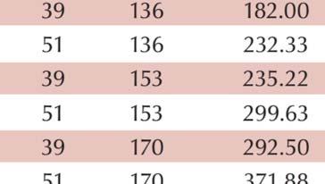
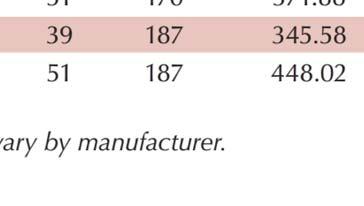
30 Treatment will be provided using Permavoid units or approved equal. Each Permavoid unit is approximately 95% void space and stores about cubic feet of water. Permavoid will be used for two purposes at the proposed project. An upper layer of Permavoid units will directly underlie landscaping, and water trapped in the Permavoid will be used for passive landscape irrigation. Captured water is wicked up from the Permavoid storage to the soil immediately above the Permavoid, where plant roots can take it up. These Permavoid units will be protected with an impervious liner and an elevated outlet/overflow structure to ensure the required volume is captured in the Permavoids. Water in excess of the water quality design volume will exit the water quality Permavoids. In the East and West drainage areas, this excess water will go into another, deeper layer of Permavoids that are used for detention only (due to being too deep to allow the stored water to be wicked up to the soil above the underground storage) or to an above ground detention basin. Only the volume of Permavoids designed for water quality (retention and reuse via passive irrigation) are counted in the calculations below. See the grading plan sheets for additional details on Permavoid installation configuration and dimensions. Retention/Reuse Area Sizing DMA(s) Remaining Runoff to be Treated (V R ) Number of Permavoid Units Total Storage Volume (cf) 1 Total Volume Sufficient? 2 West 1, ,637 Yes East 1, ,363 Yes South; Park Ave, North Yes Park Ave, South Yes Notes -Blue cells will be automatically calculated based on the inputs in other cells. -DMA ID and V R are taken from Table Based on % void. E.g. a 5 sf x 2' deep gravel filled area (4% void) has 4 cf of storage. 2. To be "sufficient", Total Volume must be greater than or equal to V R for the DMA.
31 Appendix F. Calculations for Hydromodification Management Flow Control and Flood Control Storage
32 A. Hydromodification Calculations To demonstrate compliance with hydromodification management requirements, the post-project 1- year peak flows must not exceed the pre-project 1-year peak flow rates. Runoff calculations were performed for peak flows for the 1-year storm using the rational method. The equation for peak flow calculations is as follows: Q = CIA, where Pre-Project Conditions Q Peak flow rate (cfs) C Runoff coefficient (dimensionless) I Intensity (in/hr) A Area (acres) Drainage areas were delineated based on existing topography (Map F-1). Runoff coefficients for pervious and impervious areas were assigned based on the standard runoff coefficient ranges in the Caltrans Highway Design Manual, and a weighted average runoff coefficient was calculated based on the relative amounts of pervious and impervious area in each drainage area. The East Central drainage area has a higher runoff coefficient because the eastern half of 5 th Street comprises about half of the drainage area. Table F-1. Existing Condition Runoff Coefficients Existing Drainage Area Drains to Area (acres) Impervious (acres) % Impervious C (Pervious) C (Impervious) Weighted Average C West West Central East Central East Inlet at SE side of 6th & Adams % Inlet at SW side of 5th & Adams % Inlet at SE side of 5th & Adams % Inlet at NW side of 4th & Park.62 % Note: C is the runoff coefficient Intensity is calculated based on local rainfall data and time of concentration. For all drainage areas, the travel path includes sheet flow over grass/dirt areas in the existing park, which then reaches the curb gutter of adjacent streets and becomes concentrated flow in the curb gutter. Sheet flow duration was calculated using the following formula, which is provided in the Caltrans Highway Design Manual: F-1
33 where, T t Travel time (min) L Flow path length (ft) n Manning s roughness coefficient for sheet flow P 2 2-year, 24-hour rainfall depth (1.1 in per NOAA Atlas 14) s Longitudinal slope along flow path In the existing condition grass cover at the project site is sparse, so a Manning s n between the values for fallow (.5) and short grass prairie (.15) was used. Curb gutter flow travel time was estimated by calculating a curb gutter velocity and applying that to the length of flow in the gutter. The following equation was used to calculate curb gutter velocity: For both sheet flow and gutter flow, the travel path length and longitudinal slope are based on measurements from existing topography maps. The road pavement cross slope was set at.3, the gutter Manning s n was set at.12, and the width of flow was estimated at 8 feet. The total time of concentration was calculated based on the sum of sheet flow travel time and curb gutter travel time, as summarized in the table below. Table F-2. Existing Condition Times of Concentration Sheet Flow Travel Time Curb Gutter Travel Time Existing Drainage Area L (ft) n s T c, Sheet Flow (min) L s v (fps) T c, Curb Gutter (min) Total T c (min) West West Central East Central East F-2
34 Intensity (in/hr) To calculate intensity, an intensity duration frequency (IDF) curve was developed by importing NOAA Atlas 14 precipitation data 1 for the El Centro rain gauge (EL CENTRO 2 SSW) into HydroCAD software, which then developed an IDF table and curve. The IDF table from HydroCAD was plotted in Excel, and a power equation was developed to calculate the intensity based on the time of concentration (duration). The IDF curve and equation are shown in Figure F-1 below Yr Intensity Duration Frequency y = x R² = Yr Intensity Duration Frequency Power (1-Yr Intensity Duration Frequency) Duration (min) Figure F-1. 1-Year Storm IDF Curve Based on the IDF curve and equation above, the intensity for each drainage area was calculated, and the intensity was used to calculate the 1-year existing condition peak flows. Table F-3. Existing Condition 1-Year Storm Peak Flows Existing Drainage Area Total T c (min) 1-yr I (in/hr) Weighted Average C Area (acres) Q 1 (cfs) West West Central East Central East NOAA Atlas 14 Precipitation Data Frequency Server, F-3
35 Post-Project Conditions Post-project drainage areas are shown on the drainage management area (DMA) map in Appendix C. The East and West DMAs drain to detention basins. The South DMA drains to Park Avenue, where it enters the storm drain system at the same point as the discharge from the East DMA detention basin. The Park Ave, North and Park Ave, South DMAs are not considered in the hydromodification calculations since these areas are roads with the same footprint and impervious area in the pre- and post-project conditions, so there should not be any change in the 1-year storm runoff as a result of pavement replacement in these areas. The post-project peak flow for the South DMA, which does not drain to a detention basin, was calculated using the same methodology as the existing condition peak flows. Table F-4. Post-Project Condition South DMA Runoff Coefficient DMA Area (Ac) Impervious (Ac) % Impervious C (Pervious) C (Impervious) Weighted Average C South % Table F-5. Post-Project Condition South DMA Time of Concentration Sheet Flow Travel Time Curb Gutter Travel Time T c, Sheet Flow T c, Curb Gutter Total T c DMA L (ft) n s (min) L s v (fps) (min) (min) South Table F-6. Proposed Condition South DMA 1-Year Storm Peak Flow Total T c 1-yr I Weighted Area Q 1 DMA (min) (in/hr) Average C (acres) (cfs) South The peak flow from the DMAs draining to detention basins was calculated based on applying the orifice equation to determine the maximum flow from the detention basins. The orifice size was set such that the total post-project flow to a given discharge point would not exceed the pre-project flow for the 1- year storm, as summarized in Table F-7. F-4
36 Table F-7. Target Basin Outlet Flow Rates Post-Project Discharge Point Existing Drainage Areas Draining to Post- Project Discharge Point Proposed DMA(s) 1-yr Peak Flow, Existing Condition (cfs) Proposed Condition Flow not Directed to Basin (cfs) Maximum Basin Outlet Flow (cfs) Storm drain at SE side of 6th & Adams West West Storm drain at NW side of 4th & Park West Central, East Central, East East, South Runoff volumes were calculated using the following formula: V = CPA, where V Runoff volume (cf) C Runoff coefficient (dimensionless) P Precipitation depth (ft) A Area (ft 2 ) Table F-8. Post-Project Condition 1-Year Runoff Volumes for East and West DMAs Runoff Coefficient (C), Based on Comparable Land Use 1-Year, 24- Hour Storm Volume (cf) DMA Area (Ac) % Impervious West %.68 6,396 East %.57 5,363 Note: the 1-year, 24-hour storm is 1.95 per NOAA Atlas 14. At the 1-year storm volumes above, the water surface elevation in the detention basins will not exceed 6 feet for the West Basin and 6.2 feet for the East Basin (theses elevations correspond to the basins being full, and their capacities hold a 3 inch storm). The West Basin orifice size is set at 1.5 inches, and the East Basin orifice size is set at 2.5 inches. At these orifice sizes, the maximum discharge rates from the basins will not exceed the maximum values shown in Table F-7, as shown below in Table F-9. Table F-9. Orifice Flow Rate Calculations for the East and West Basins West Basin (Max outflow =.18 cfs) East Basin (Max outflow =.52 cfs) C v Water Ponding above Outlet (feet) Orifice Pipe Diameter (in) Velocity from Orifice (ft/s) Flow from Orifice (cfs) As shown in Table F-1 below, the post-project 1-year peak flows are less than the pre-project 1-year peak flows, so the hydromodification management requirements have been met. F-5
37 Table F-1. 1-Year Peak Flow Summary Existing Drainage Areas Draining to Post-Project Discharge Point 1-yr Peak Flow, Existing Condition (cfs) 1-yr Peak Flow, Post- Project Condition (cfs) Post-Project Discharge Point Proposed DMA(s) Storm drain at SE side of 6th & Adams West West.18.14* Yes Storm drain at NW side of 4th & Park West Central, East Central, East Hydromodification Requirements Met East, South.96.85** Yes Notes: To meet hydromodification requirements, the post-project peak flow must be less than or equal to the pre-project peak flow for each discharge point. * Maximum outflow from West Basin ** Maximum outflow from East Basin plus post-project 1-yr peak flow from South Basin. B. Flood Control Storage Calculations Flood control storage calculations are based on a 3 inch storm per City of El Centro policy. The Park Ave, North and Park Ave, South DMAs are not included in the calculations since the existing and proposed condition of these areas will be the same (paved road). Therefore, there will be no additional runoff from those areas in the post-project condition and no need for additional storage to mitigate flooding impacts. Runoff from the South DMA is also not included because at.3 acres, it is a comparatively small portion of the site and it is less than the size of the existing impervious road segment (5 th Street between Adams Avenue and Park Avenue, which is about.46 acre) part of the site that does not have any detention storage in the existing condition. Runoff volumes for a 3 inch storm for the West and East DMAs are shown in Table F-11. Table F-12 illustrates how above and below ground basins have been designed to store at least this amount of water and shows that total basin drawdown time is less than 72 hours, which is necessary to meet vector control requirements. Table F-11. Three Inch Storm Runoff Volume Summary Runoff Coefficient (C), Based on Comparable Land Use 1-Year Storm Runoff Coefficient* 3" Storm Runoff Volume Drainage Area Area (Ac) % Impervious West % ,31 East % ,277 Note: * As dictated by the procedure in the Caltrans Highway Design Manual, the 1-year storm runoff coefficient is 1.25 times the initial runoff coefficient determined by comparison to comparable land use. F-6
38 Intensity (in/hr) Table F-12. Provided Basin Storage Note: DMA Provided Above Ground Storage (cf) Permavoid Units Proposed Underground Storage (cf) Total Storage Provided (cf) Basin Drawdown Time (hr)* West 3, ,726 12, East 6, ,744 1, * Per vector control requirements, must be less than 72 hours. C. 25-Year and 1-Year Storm Calculations for Caltrans The peak flows in the pre- and post-project conditions associated with the 25-year, 6-hour and 1-year, 6-hour storms were compared using the same methodology described in Section A above for the comparison of 1-year peak flows, except that different IDF curves were used to calculate the intensities and C values were increased per the procedure in the Caltrans Highway Design Manual. The 25-year and 1-year IDF curves in Figures F-2 and F-3, respectively, were developed based on NOAA Atlas 14 data using the same methodology used to develop the 1-year IDF curve described in Section A Yr Intensity Duration Frequency y = 1.821x R² = Yr Intensity Duration Frequency Power (25-Yr Intensity Duration Frequency) Duration (min) Figure F Year Storm IDF Curve F-7
39 Intensity (in/hr) 1-Yr Intensity Duration Frequency y = x R² = Yr Intensity Duration Frequency Power (1-Yr Intensity Duration Frequency) Duration (min) Figure F-3. 1-Year Storm IDF Curve Calculations for the 25-year and 1-year peak flows are summarized in the following tables. Table F-13. Existing Condition 25-Year Storm Peak Flows Existing Drainage Area Total T c (min) 25-Yr I (in/hr) 25-Yr C* Area (acres) Q 1 (cfs) West West Central East Central East * Per the methodology described in the Caltrans Highway Design Manual, the 25-yr C value is 1.1 times the initial C value as determined via the process described in Section A of this report or.95, whichever is less. F-8
40 Table F-14. Existing Condition 1-Year Storm Peak Flows Existing Drainage Area Total T c (min) 1-Yr I (in/hr) 1-Yr C* Area (acres) Q 1 (cfs) West West Central East Central East * Per the methodology described in the Caltrans Highway Design Manual, the 25-yr C value is 1.25 times the initial C value as determined via the process described in Section A of this report or.95, whichever is less. Table F-15. Proposed Condition South DMA 1-Year Storm Peak Flow Total T c 25-Yr I Area Q 1 DMA (min) (in/hr) 25-Yr C* (acres) (cfs) South * Per the methodology described in the Caltrans Highway Design Manual, the 25-yr C value is 1.1 times the initial C value as determined via the process described in Section A of this report or.95, whichever is less. Table F-16. Proposed Condition South DMA 1-Year Storm Peak Flow Total T c 1-Yr I Area Q 1 DMA (min) (in/hr) 1-Yr C* (acres) (cfs) South * Per the methodology described in the Caltrans Highway Design Manual, the 25-yr C value is 1.25 times the initial C value as determined via the process described in Section A of this report or.95, whichever is less. As described in Section B, the East and West basins have the capacity to hold runoff from a 3 inch storm. Per NOAA Atlas 14, the 1-year, 6-hour storm is 2.5 inches. Therefore, the proposed basins have the capacity to capture all runoff from the 25-year and 1-year storms. This means the peak outflow from these basins in the post-project condition can be calculated based on the orifice equation, as done in Section A for the 1-year peak flow. The calculations in Table F-9 are based on the basins being completely full (head values of 6 feet and 6.2 feet). Therefore, the flow rates as calculated for these head values using the orifice equation are conservative estimates of the outflows from the basins during 25-year and 1-year storms. Tables F-17 and F-18 summarize the results of the calculations, which show that the post-project peak flows are less than the existing condition peak flows. F-9
41 Table F Year Peak Flow Summary Existing Drainage Areas Draining to Post-Project Discharge Point 25-yr Peak Flow, Existing Condition (cfs) 25-yr Peak Flow, Post- Project Condition (cfs) Post-Project Peak Flow Less Than Existing Condition Peak Flow? Post-Project Discharge Point Proposed DMA(s) Storm drain at SE side of 6th & Adams West West.27.14* Yes Storm drain at NW side of 4th & Park West Central, East Central, East East, South ** Yes Notes: * Maximum outflow from West Basin ** Maximum outflow from East Basin (see Table F-9) plus post-project 25-yr peak flow from South Basin. Table F Year Peak Flow Summary Existing Drainage Areas Draining to Post-Project Discharge Point 1-yr Peak Flow, Existing Condition (cfs) 1-yr Peak Flow, Post- Project Condition (cfs) Post-Project Peak Flow Less Than Existing Condition Peak Flow? Post-Project Discharge Point Proposed DMA(s) Storm drain at SE side of 6th & Adams West West.45.14* Yes Storm drain at NW side of 4th & Park West Central, East Central, East East, South ** Yes Notes: * Maximum outflow from West Basin ** Maximum outflow from East Basin(see Table F-9) plus post-project 1-yr peak flow from South Basin. F-1

42 Map F-1. Existing Condition Drainage Areas F-
43 Appendix G. Source Control BMPs Proposed and Plan Sheet References
44 Source Control BMPs Proposed and Plan Sheet References Source Control BMP Description CASQA Reference 1 Proposed? (Y/N/NA) Plan Sheet Reference If NA or Not Shown on Plans, Explain Why Accidental spills or leaks Keep a spill kit or other means of responding to spills onsite. Liquid storage containers kept outdoors must be equipped with secondary containment unless the liquid stored contains no pollutants (e.g., purified water). Secondary containment design and spill response materials available onsite may also need to meet the requirements of other standards (e.g., hazardous materials, fire department). -- Y NA Will be inside buildings. Mops or rags will be onsite to clean up food and drink spills. Materials to clean up chemicals associated with pools will also be present as applicable. Interior floor drains Parking/storage areas and maintenance Indoor and structural pest control Landscape/ outdoor pesticide use Plumb indoor floor drains to the sanitary sewer system. Pretreatment is required where necessary to comply with City wastewater regulations. Design parking areas to drain to landscaping or LID features where feasible. Complete regular sweeping or other cleaning of parking areas as necessary to remove accumulated trash, sediment, and other pollutants. Use integrated pest management to avoid or minimize pesticide use where feasible, and use pesticides only in accordance with manufacturer s instructions. See BMP A- 1 in Table 1 of the El Centro BMP Manual. Use integrated pest management to avoid or minimize pesticide use where feasible, and use pesticides only in accordance with manufacturer s instructions. See BMP A- 1 in Table 1 of the El Centro BMP Manual. Also use native plants or other plants that require minimal pesticide use as feasible. -- Y NA -- Y Grading sheets Flood drains are not shown on grading plans -- Y NA Nonstructural BMP -- Y NA Nonstructural BMP
45 Source Control BMPs Proposed and Plan Sheet References Source Control BMP Description CASQA Reference 1 Proposed? (Y/N/NA) Plan Sheet Reference If NA or Not Shown on Plans, Explain Why Pools, spas, ponds, decorative fountains, and other water features Discharges from water features to the municipal separate storm sewer system (MS4) are only allowed in certain cases. See BMP A-5 in Table 1 of the El Centro BMP Manual for pool and spa discharge regulations. Discharges from ponds, decorative fountains, and other water features to the MS4 are typically not allowed. -- Y NA Primarily nonstructural/ operational BMP Restaurants, grocery stores, and other food service operations Provide a covered, contained storage area for used cooking oil. This requirement may be satisfied by storing used cooking oil inside a building (ensure health regulations and fire department regulations are met) or in a refuse area designed to meet the requirements described below. -- Y Building/ Architectural Plans Same location as refuse area Refuse areas Equip the refuse area with a structural overhead canopy and a four-sided enclosure. Site drainage should be directed away from the refuse area to prevent run-on. No storm drains are allowed within refuse areas. SD-32 Y Building/ Architectural Plans Industrial processes Design facilities such that industrial processes are located indoors or in covered areas protected from run-on to the extent feasible. Where applicable, industrial processes must be designed to comply with State of California Industrial General Permit requirements. SD-31, SD- 35 NA Will not occur at proposed project
Water Resources Management Plan
 B u r n s v i l l e M i n n e s o t a Water Resources Management Plan - Volume Control / Infiltration Worksheet This Appendix contains a worksheet and related information that can be used for evaluating
Sizing Calculations and Design Considerations for LID Treatment Measures
 SCVURPPP C.3 Workshop December 18, 2012 Sizing Calculations and Design Considerations for LID Treatment Measures Jill Bicknell, P.E., EOA, Inc. Santa Clara Valley Urban Runoff Pollution Prevention Program
June 2017 C.3 Workshop Sizing Example. Section II.B Sizing Volume-Based Treatment Measures based on the Adapted CASQA Stormwater BMP Handbook Approach
 SANTA CLARA VALLEY URBAN RUNOFF POLLUTION PREVENTION PROGRAM June 2017 C.3 Workshop Sizing Example Section II. Sizing for Volume-Based Treatment Measures Section II.B Sizing Volume-Based Treatment Measures
Stormwater Treatment Measure Sizing and Design Considerations SMCWPPP C.3 Workshop June 21, 2017
 Stormwater Treatment Measure Sizing and Design Considerations SMCWPPP C.3 Workshop June 21, 2017 Jill Bicknell, P.E., EOA, Inc. Presentation Overview Sizing/Design of Self Treating and Self Retaining Areas
CENTRALIZED BMPS TYPICALLY PUBLICLY OWNED & MAINTAINED BMPS, TREATING A LARGE (>20 ACRES) URBAN DRAINAGE WITH MULTIPLE LAND
 URBAN DRAINAGE WITH MULTIPLE LAND") BMP RAM BMP Type Definitions 1 CENTRALIZED BMPS TYPICALLY PUBLICLY OWNED & MAINTAINED BMPS, TREATING A LARGE (>20 ACRES) URBAN DRAINAGE WITH MULTIPLE LAND USES AND OWNERSHIP STRUCTURAL BMP TYPE OTHER NAMES
BMP RAM BMP Type Definitions 1 CENTRALIZED BMPS TYPICALLY PUBLICLY OWNED & MAINTAINED BMPS, TREATING A LARGE (>20 ACRES) URBAN DRAINAGE WITH MULTIPLE LAND USES AND OWNERSHIP STRUCTURAL BMP TYPE OTHER NAMES
Design Handbook. Low Impact Development Best Management Practices
 Design Handbook for Low Impact Development Best Management Practices Prepared by: 9/2011 Riverside County Flood Control and Water Conservation District 1995 Market Street Riverside, CA 92501 TABLE OF CONTENTS
Design Example Residential Subdivision
 Design Example Residential Subdivision Rhode Island Stormwater Design and Installation Standards Manual December 2010 Public Training March 22, 2010 Richard Claytor, P.E. 508-833-6600 Appendix D: Site
Example 1: Pond Design in a residential development (Water Quantity calculations for a Wet Pond and Wet Extended Detention Pond)
") Chapter 10 Design Examples Example 1: Pond Design in a residential development (Water Quantity calculations for a Wet Pond and Wet Extended Detention Pond) Example 2: Filter Design in a commercial development
Chapter 10 Design Examples Example 1: Pond Design in a residential development (Water Quantity calculations for a Wet Pond and Wet Extended Detention Pond) Example 2: Filter Design in a commercial development
APPENDIX J-3. Orcem Stormwater Management and Treatment Facilities Design Summary
 APPENDIX J-3 Orcem Stormwater Management and Treatment Facilities Design Summary Stormwater Management & Treatment Facilities Design Summary INTRODUCTION KPFF Consulting Engineers has compiled this report
Water Resources Management Plan Appendix B
 B u r n s v i l l e M i n n e s o t a Water Resources Management Plan Appendix B Appendix B Page B-1 Burnsville, Minnesota STORM WATER LOW-IMPACT DEVELOPMENT GUIDE MANUAL SHORT ELLIOTT HENDRICKSON INC.
PRELIMINARY DRAINAGE REPORT NEWCASTLE FIRE STATION OLD STATE HIGHWAY
 PRELIMINARY DRAINAGE REPORT FOR THE NEWCASTLE FIRE STATION OLD STATE HIGHWAY PREPARED FOR THE NEWCASTLE FIRE PROTECTION DISTRICT JULY 2014 BY ROSEVILLE DESIGN GROUP, INC. ROSEVILLE DESIGN GROUP, Inc Established
PRELIMINARY DRAINAGE STUDY
 PRELIMINARY DRAINAGE STUDY For 34 th & J Residences 3402 J St. San Diego, CA 92102 A.P.N 545-250-08 Prepared By: Kenneth J. Discenza, P.E. Site Design Associates, Inc. 1016 Broadway, Suite A El Cajon,
Pollutant Sources/Source Controls Checklist A-7
 A P P E N D I X 7 Pollutant Sources/Source Controls Checklist A-7 Stormwater Pollutant Sources/Source Controls Checklist How to use this worksheet (also see instructions on Checklist for Regulated Projects):
Stormwater Treatment Practice (STP) Calculator Instructions
 Calculator Instructions") Stormwater Treatment Practice (STP) Calculator Instructions The STP Calculator is a tool developed by the Department of Environmental Conservation (DEC) to estimate total phosphorus load reductions achieved
Stormwater Treatment Practice (STP) Calculator Instructions The STP Calculator is a tool developed by the Department of Environmental Conservation (DEC) to estimate total phosphorus load reductions achieved
Hydrology Study. For Bella Terrazza Portion of Lot 1, Block 39, Subdivision of S Tract, Rancho El Cajon El Cajon, CA 92021
 Hydrology Study For Bella Terrazza Portion of Lot 1, Block 39, Subdivision of S Tract, Rancho El Cajon El Cajon, CA 92021 Prepared for Daryl Priest - Priest Development Corporation 124 West Main Street,
EXAMPLE Stormwater Management Plans w/ CSS BMP Sizing Calculator (v2.1)
") 525 Golden Gate Avenue, 11th Floor San Francisco, CA 94102 EXAMPLE Stormwater Management Plans w/ CSS BMP Sizing Calculator (v2.1) The following example Stormwater Management Plans (SMPs) are provided
525 Golden Gate Avenue, 11th Floor San Francisco, CA 94102 EXAMPLE Stormwater Management Plans w/ CSS BMP Sizing Calculator (v2.1) The following example Stormwater Management Plans (SMPs) are provided
Worksheets from Orange County Technical Guidance Document ( )
") Worksheets from Orange County Technical Guidance Document (5-19-2011) : Table 2.7: Infiltration BMP Feasibility Worksheet 1 Provide basis: Infeasibility Criteria Yes No Would Infiltration BMPs pose significant
Worksheets from Orange County Technical Guidance Document (5-19-2011) : Table 2.7: Infiltration BMP Feasibility Worksheet 1 Provide basis: Infeasibility Criteria Yes No Would Infiltration BMPs pose significant
Modeling Green Infrastructure Compared with Large-Scale Monitoring at Kansas City, MO
 X Modeling Green Infrastructure Compared with Large-Scale Monitoring at Kansas City, MO Robert Pitt and Leila Talebi The US EPA s Green Infrastructure Demonstration project in Kansas City, MO, is likely
THE SAN DIEGO AND IMPERIAL COUNTIES CHAPTER OF THE AMERICAN PUBLIC WORKS ASSOCIATION (APWA) ANNOUNCE A SEMINAR DEMONSTRATING The BMP Sizing
 ANNOUNCE A SEMINAR DEMONSTRATING The BMP Sizing") THE SAN DIEGO AND IMPERIAL COUNTIES CHAPTER OF THE AMERICAN PUBLIC WORKS ASSOCIATION (APWA) ANNOUNCE A SEMINAR DEMONSTRATING The BMP Sizing Spreadsheeet A Tool to Comply with Hydromodification Management
THE SAN DIEGO AND IMPERIAL COUNTIES CHAPTER OF THE AMERICAN PUBLIC WORKS ASSOCIATION (APWA) ANNOUNCE A SEMINAR DEMONSTRATING The BMP Sizing Spreadsheeet A Tool to Comply with Hydromodification Management
IBS Site Drainage: Senior Design Project
 IBS Site Drainage: Senior Design Project Len Wright, Ph.D., PE Lecturer, CEAE Wright.Len@gmail.com September 11, 2008 mwsw204i1.ppt/1 OUTLINE Motivation for Stormwater Management Quantity (both onsite,
Concurrent Session B: LID Design Specifications (Chapter 4 in Draft Manual)
") Concurrent Session B: LID Design Specifications (Chapter 4 in Draft Manual) Should vs. Must In Chapter 4, should means should, and must means must. Poorly Drained Soils Well-Drained Soils Flat Terrain
Concurrent Session B: LID Design Specifications (Chapter 4 in Draft Manual) Should vs. Must In Chapter 4, should means should, and must means must. Poorly Drained Soils Well-Drained Soils Flat Terrain
100-yr Design Runoff (cfs) Basin ID 103b A a B B C Totals
 Basin ID 103b A a B B C Totals") PROPOSED DEVELOPMENT The drainage for this site has been designed to be less than the maximum allowable runoff from each basin as stated in the Overall Rigden Farm drainage plan. Table 1 compares the actual
PROPOSED DEVELOPMENT The drainage for this site has been designed to be less than the maximum allowable runoff from each basin as stated in the Overall Rigden Farm drainage plan. Table 1 compares the actual
Appendix A. Compliance Calculator Guidance
 Compliance Calculator Guidance Appendix A Appendix A. Compliance Calculator Guidance A.1 Introduction The Center for Watershed Protection created the compliance calculator spreadsheet to allow a designer
Chapter 6. Hydrology. 6.0 Introduction. 6.1 Design Rainfall
 6.0 Introduction This chapter summarizes methodology for determining rainfall and runoff information for the design of stormwater management facilities in the City. The methodology is based on the procedures
Treatment Volume: Curve Numbers. Composite CN or Not? Treatment Volume: Curve Numbers. Treatment Volume: Calculation. Treatment Volume: Calculation
 Stormwater Engineering Bioretention Design Bill Hunt, PE, Ph.D. Extension Specialist & Assistant Professor NCSU-BAE www.bae.ncsu.edu/stormwater Bioretention Design Six Step Process 1 Determine Volume to
RETENTION BASIN EXAMPLE
 -7 Given: Total Tributary Area = 7.5 ac o Tributary Area within Existing R/W = 5.8 ac o Tributary Area, Impervious, Outside of R/W = 0.0 ac o Tributary Area, Pervious, Outside of R/W = 1.7 ac o Tributary
Chatham Park Stormwater Manual
 Chatham Park Stormwater Manual Table of Contents A. Introduction... 2 B. Calculation Methods... 2 C. BMP Design Standards... 3 D. Compliance Points... 3 E. Critical Environmental Resources... 3 F. Submittal
Hydrology for Drainage Design. Design Considerations Use appropriate design tools for the job at hand:
 Hydrology for Drainage Design Robert Pitt Department of Civil and Environmental Engineering University of Alabama Tuscaloosa, AL Objectives for Urban Drainage Systems are Varied Ensure personal safety
January 20, Nate Hatleback Project Manager, City of Thornton Development Engineering 9500 Civic Center Drive Thornton, CO (303)
") January 20, 2017 Nate Hatleback Project Manager, City of Thornton Development Engineering 9500 Civic Center Drive Thornton, CO 80229 (303) 538-7694 RE: Riverdale Five Retail Drainage Conformance Letter
January 20, 2017 Nate Hatleback Project Manager, City of Thornton Development Engineering 9500 Civic Center Drive Thornton, CO 80229 (303) 538-7694 RE: Riverdale Five Retail Drainage Conformance Letter
Sizing Criteria Worksheets and Examples
 Appendix B Sizing Criteria Worksheets and Examples This Appendix provides sizing criteria worksheets and examples to illustrate the correct procedures for determining the water quality design flow and
Appendix A. Stormwater Pollutant Sources/Source Controls Checklist
 Appendix A. Stormwater Pollutant Sources/Source Controls Checklist How to use this worksheet (also see instructions on page -6 of the Stormwater Technical Guide):. Review Column and identify which of these
Permeable Pavement: A New Chapter
 Permeable Pavement: A New Chapter Annette Lucas, PE (919) 807-6381 annette.lucas@ncdenr.gov NC Division of Water Quality Wetlands & Stormwater Branch Final Chapter Released: October 16, 2012 We Bring Engineering
ORDINANCE APPENDIX F STORMWATER MANAGEMENT DESIGN CRITERIA
 ORDINANCE APPENDIX F STORMWATER MANAGEMENT DESIGN CRITERIA TABLE F-1 DESIGN STORM RAINFALL AMOUNT FIGURE F-1 ALTERNATING BLOCK METHOD FOR RAINFALL DISTRIBUTION FIGURE F-2 PENNDOT DELINEATED REGIONS FIGURE
HYDROLOGIC CONSIDERATIONS. 22 nd Annual Nonpoint Source Pollution Conference Saratoga Springs, NY
 LOW IMPACT DEVELOPMENT HYDROLOGIC CONSIDERATIONS 22 nd Annual Nonpoint Source Pollution Conference Saratoga Springs, NY May 18, 2011 PRESENTATION AGENDA Introduction Definitions Discuss Impacts to Hydrologic
Tips for Preparing/Reviewing Storm Water Control Plans (SWCP)
") Tips for Preparing/Reviewing Storm Water Control Plans (SWCP) Kristin Kerr, P.E. EOA, Inc. San Mateo Countywide Water Pollution Prevention Program June 21, 2017 Presentation Outline Important Resources
Tips for Preparing/Reviewing Storm Water Control Plans (SWCP) Kristin Kerr, P.E. EOA, Inc. San Mateo Countywide Water Pollution Prevention Program June 21, 2017 Presentation Outline Important Resources
6.0 Runoff. 6.1 Introduction. 6.2 Flood Control Design Runoff
 October 2003, Revised February 2005 Chapter 6.0, Runoff Page 1 6.1 Introduction 6.0 Runoff The timing, peak rates of discharge, and volume of stormwater runoff are the primary considerations in the design
LAKE COUNTY HYDROLOGY DESIGN STANDARDS
 LAKE COUNTY HYDROLOGY DESIGN STANDARDS Lake County Department of Public Works Water Resources Division 255 N. Forbes Street Lakeport, CA 95453 (707)263-2341 Adopted June 22, 1999 These Standards provide
Appendix 10-A. Optional Recharge Volume Approach
 Appendix 10-A Optional Recharge Volume Approach Table of Contents APPENDIX SECTION HEADINGS 10-A.0 INTRODUCTION 10-A-2 10-A.1 Horsely Method for Determining Recharge Volumes 10-A-2 10-A.1.1 Basis for Determining
County of Los Angeles - Department of Public Works
 GENERAL PROJECT INFORMATION County of Los Angeles - Department of Public Works Building and Safety/Land Development Division LOW IMPACT DEVELOPMENT REVIEW SHEET (2017 Los Angeles County Building Code,
FORT COLLINS STORMWATER CRITERIA MANUAL Hydrology Standards (Ch. 5) 1.0 Overview
 1.0 Overview") Chapter 5: Hydrology Standards Contents 1.0 Overview... 1 1.1 Storm Runoff Determination... 1 1.2 Design Storm Frequencies... 1 1.3 Water Quality Storm Provisions... 2 1.4 Design Storm Return Periods...
Chapter 5: Hydrology Standards Contents 1.0 Overview... 1 1.1 Storm Runoff Determination... 1 1.2 Design Storm Frequencies... 1 1.3 Water Quality Storm Provisions... 2 1.4 Design Storm Return Periods...
NON-PRIORITY PROJECT WATER QUALITY PLAN (NPP)
") NON-PRIORITY PROJECT WATER QUALITY PLAN (NPP) For: (Insert Project Name) (Site Address or Tract/Lot Number) Prepared for: (Insert Owner/Developer Name) (Insert Address) (Insert City, State, ZIP) (Insert
NON-PRIORITY PROJECT WATER QUALITY PLAN (NPP) For: (Insert Project Name) (Site Address or Tract/Lot Number) Prepared for: (Insert Owner/Developer Name) (Insert Address) (Insert City, State, ZIP) (Insert
10/16/2013. The Big Picture of LID and Green Infrastructure. Learning Objectives
 Low impact development (LID) the basic idea behind LID is to manage stormwater in a way that imitates the natural hydrology of a site. Details Matter Selection, Design, and Implementation of Low Impact
Module 10b: Gutter and Inlet Designs and Multiple Design Objectives
 Module 10b: Gutter and Inlet Designs and Multiple Design Objectives Bob Pitt University of Alabama and Shirley Clark Penn State Harrisburg Evening traffic plows through high water at the intersection of
Extended Detention Basin Design
 Extended Detention Basin Design 1 Extended Detention 2 Ohio Department of Transportation 1 Extended Detention Basin L&D Vol. 2 Section 1117.3 Provides quality and quantity treatment 3 Extended Detention
Municipal Stormwater Ordinances Summary Table
 APPENDIX F Municipal Ordinances Summary Table Municipality Abington Bryn Athyn Borough Hatboro Borough Ordinance, SALDO Runoff equals pre post Erosion Sediment Control Water Quality Requirements Any which
Rational Method Hydrological Calculations with Excel COURSE CONTENT
 Rational Method Hydrological Calculations with Excel Harlan H. Bengtson, PhD, P.E. COURSE CONTENT 1. Introduction Calculation of peak storm water runoff rate from a drainage area is often done with the
Practices that capture and temporarily store the WQ v before allowing it to infiltrate into the soil.
 Chapter 5: Acceptable Stormwater Management Practices (SMPs) This section presents a list of practices that are acceptable for water quality treatment. The practices on this list are selected based on
Conservation Design Approach for New Development
 Effective Best Management Practices in Urban Areas Chad Christian City of Tuscaloosa, AL Robert Pitt University of Alabama Tuscaloosa, AL Energy Independence and Security Act of 2007 signed into Law on
November 21, City of Thornton 9500 Civic Center Drive Thornton, CO (303) RE: Maverik Thornton, CO - Drainage Report
 RE: Maverik Thornton, CO - Drainage Report") November 21, 2016 City of Thornton 9500 Civic Center Drive Thornton, CO 80229 (303) 538-7295 RE: Maverik Thornton, CO - Drainage Report As per your request, we are submitting to you the drainage report
November 21, 2016 City of Thornton 9500 Civic Center Drive Thornton, CO 80229 (303) 538-7295 RE: Maverik Thornton, CO - Drainage Report As per your request, we are submitting to you the drainage report
SIZING. MWS Linear. Hybrid Stormwater Filtration System. P.O. Box 869 P Oceanside, CA F
 SIZING MWS Linear Hybrid Stormwater Filtration System Modular Wetland Systems, Inc. www.modularwetlands.com P.O. Box 869 P 760-433-7640 Oceanside, CA 92049 F 760-433-3179 SIZING Many municipal stormwater
Design of Stormwater Wetlands
 Hydraulic & Hydrologic Stormwater Engineering Design of Stormwater Wetlands Jon Hathaway, EI Extension Associate NCSU Bio. And Ag. Engineering 6 Step Process 1. Watershed Analysis (Runoff Volume and Peak
STORMWATER QUALITY CONTROL PLAN (SWQCP)
") STORMWATER QUALITY CONTROL PLAN (SWQCP) SPERRY ROAD EXTENSION FRENCH CAMP RD. TO PERFORMANCE DR. CITY OF STOCKTON COUNTY OF SAN JOAQUIN Prepared at the Request of: CITY OF STOCKTON PUBLIC WORKS DEPARTMENT
STORMWATER QUALITY CONTROL PLAN (SWQCP) SPERRY ROAD EXTENSION FRENCH CAMP RD. TO PERFORMANCE DR. CITY OF STOCKTON COUNTY OF SAN JOAQUIN Prepared at the Request of: CITY OF STOCKTON PUBLIC WORKS DEPARTMENT
DESIGN DEVELOPMENT HYDROLOGY REPORT & LOW IMPACT DEVELOPMENT PLAN (LID PLAN)
") DESIGN DEVELOPMENT HYDROLOGY REPORT & LOW IMPACT DEVELOPMENT PLAN ( PLAN) ALAMITOS BEACH CONCESSION BUILDING 780 E. SHORELINE DRIVE LONG BEACH, CALIFORNIA Prepared For: Long Beach Public Works 333 W. Ocean
DESIGN DEVELOPMENT HYDROLOGY REPORT & LOW IMPACT DEVELOPMENT PLAN ( PLAN) ALAMITOS BEACH CONCESSION BUILDING 780 E. SHORELINE DRIVE LONG BEACH, CALIFORNIA Prepared For: Long Beach Public Works 333 W. Ocean
Environment, Energy, Security & Sustainability (E2S2)
") Environment, Energy, Security & Sustainability (E2S2) Modeling Your Way Through EISA Patrick N. Deliman, PhD Environmental Laboratory US Army Engineer Research and Development Center US Army Corps of Engineers
Environment, Energy, Security & Sustainability (E2S2) Modeling Your Way Through EISA Patrick N. Deliman, PhD Environmental Laboratory US Army Engineer Research and Development Center US Army Corps of Engineers
Stormwater Bio-Infiltration Pilot Project Concept Proposal Submitted by
 Concept Proposal Submitted by Public Works Department 1947 Center Street, Fourth Floor Berkeley, CA 94704 December 17, 2009 Executive Summary The s Public Works Department submits this concept proposal
1. Review Column 1 and identify which of these potential sources of stormwater pollutants apply to your site. Check each box that applies.
 How to use this worksheet (also see instructions in Section G of the 0 SMR WQMP Template):. Review Column and identify which of these potential sources of stormwater pollutants apply to your site. Check
Pre-Treatment Bioretention Cells Bioswales IOWA STORMWATER MANAGEMENT MANUAL DECEMBER 16, 2015
 Pre-Treatment Bioretention Cells Bioswales IOWA STORMWATER MANAGEMENT MANUAL DECEMBER 16, 2015 Urban Runoff Background How we got here What Problem?? Provenance of the Problem Unified Sizing Criteria What
2011 Guidance Manual for Development Stormwater Quality Control Measures
 CITY OF MODESTO STORMWATER MANAGEMENT PROGRAM 2011 Guidance Manual for Development Stormwater Quality Control Measures Prepared for NPDES Permit No. CAS083526; Order R5-2008-0092 This page intentionally
the 2001 season. Allison brought high winds and street flooding to Houston, after
 Module 10b: Gutter and Inlet Designs and Multiple Design Objectives Bob Pitt University of Alabama and Shirley Clark Penn State Harrisburg Evening traffic plows through high water at the intersection of
4.12. Detention Basins
 4.12. Detention Basins Detention Basins can be a cost effective method to provide temporary storage, conveyance, and treatment of runoff when used within the context of Low Impact Development (LID) strategies.
City of Beverly Hills Low Impact Development (LID) Fact Sheet
 Fact Sheet") On May 18, 2015, the City of Beverly Hills amended its Stormwater and Urban Runoff Pollution Control Ordinance (Article 5 Chapter 4 Title 9 of the Beverly Hills Municipal Code) to include Low Impact Development
On May 18, 2015, the City of Beverly Hills amended its Stormwater and Urban Runoff Pollution Control Ordinance (Article 5 Chapter 4 Title 9 of the Beverly Hills Municipal Code) to include Low Impact Development
15A NCAC 02H.1005 STORMWATER REQUIREMENTS: COASTAL COUNTIES
 1 1 1 1 1 1 1 1 0 1 0 1 1A NCAC 0H.0 STORMWATER REQUIREMENTS: COASTAL COUNTIES (a) The following definitions are applicable to this rule: (1) Built upon area as defined in Session Law 00- means that portion
Introduction to Storm Sewer Design
 A SunCam online continuing education course Introduction to Storm Sewer Design by David F. Carter Introduction Storm sewer systems are vital in collection and conveyance of stormwater from the upstream
SFPUC Wastewater Enterprise URBAN WATERSHED MANAGEMENT PROGRAM
 525 Golden Gate Avenue 11th Floor San Francisco, CA 94102 SFPUC Wastewater Enterprise URBAN WATERSHED MANAGEMENT PROGRAM COMBINED SEWER SYSTEM (CSS) AND MUNICIPAL SEPARATE STORM SEWER SYSTEM (MS4) BMP
SFPUC Wastewater Enterprise URBAN WATERSHED MANAGEMENT PROGRAM
 525 Golden Gate Avenue 11th Floor San Francisco, CA 94102 SFPUC Wastewater Enterprise URBAN WATERSHED MANAGEMENT PROGRAM COMBINED SEWER SYSTEM (CSS) AND MUNICIPAL SEPARATE STORM SEWER SYSTEM (MS4) BMP
Engineering Division 701 Laurel Street Menlo Park, CA Phone: (650) Fax: (650)
 Fax: (650)") Engineering Division 701 Laurel Street Menlo Park, CA 94025 Phone: (650) 330-6740 Fax: (650) 327-5497 GRADING AND DRAINAGE GUIDELINES FOR SINGLE FAMILY HOME PROJECTS It is the responsibility of the property
Engineering Division 701 Laurel Street Menlo Park, CA 94025 Phone: (650) 330-6740 Fax: (650) 327-5497 GRADING AND DRAINAGE GUIDELINES FOR SINGLE FAMILY HOME PROJECTS It is the responsibility of the property
Learn how to design inlet grates, detention basins, channels, and riprap using the FHWA Hydraulic Toolbox and WMS
 v. 11.0 WMS 11.0 Tutorial Learn how to design inlet grates, detention basins, channels, and riprap using the FHWA Hydraulic Toolbox and WMS Objectives Learn how to use several Hydraulic Toolbox calculators
OHIO S NPDES STORMWATER GENERAL PERMIT FOR CONSTRUCTION ACTIVITIES OHC Justin Reinhart, PE Division of Surface Water
 OHIO S NPDES STORMWATER GENERAL PERMIT FOR CONSTRUCTION ACTIVITIES OHC00005 Justin Reinhart, PE Division of Surface Water ASCE Spring Seminar Columbus, Ohio April 26, 2018 Goals / Outline 1. CGP background
APPENDIX IV. APPROVED METHODS FOR QUANTIFYING HYDROLOGIC CONDITIONS OF CONCERN (NORTH ORANGE COUNTY)
") APPENDIX IV. APPROVED METHODS FOR QUANTIFYING HYDROLOGIC CONDITIONS OF CONCERN (NORTH ORANGE COUNTY) Hydromodification design criteria for the North Orange County permit area are based on the 2- yr, 24-hr
APPENDIX IV. APPROVED METHODS FOR QUANTIFYING HYDROLOGIC CONDITIONS OF CONCERN (NORTH ORANGE COUNTY) Hydromodification design criteria for the North Orange County permit area are based on the 2- yr, 24-hr
Stormwater Control Plan Report
 Stormwater Control Plan Report (SWCP) HILLSDALE TERRACE 2700, 2728, 2790 South El Camino Real San Mateo, CA APN: 039-352-060, 039-352-070, 039-352-090 Stormwater Control Plan Report February 18, 2015 Prepared
City of Santa Clarita Project-Specific Urban Stormwater Mitigation Plan
 Project-Specific Urban Stormwater Mitigation Plan The purpose of this checklist is to assist developers and project engineers in the preparation of a uniform and comprehensive Project-Specific Urban Stormwater
Hydrologic Study Report for Single Lot Detention Basin Analysis
 Hydrologic Study Report for Single Lot Detention Basin Analysis Prepared for: City of Vista, California August 18, 2006 Tory R. Walker, R.C.E. 45005 President W.O. 116-01 01/23/2007 Table of Contents Page
TECHNICAL GUIDANCE DOCUMENT APPENDICES
 XIV.4. Harvest and Use BMP Fact Sheets (HU) HU-1: Above-Ground Cisterns Cisterns are large rain barrels. While rain barrels are less than 100 gallons, cisterns range from 100 to more than 10,000 gallons
G. HYDROLOGY Existing Conditions
 G. HYDROLOGY Existing Conditions Surface Water Runoff This section is based on the hydrology and drainage analysis for the proposed Project, which was prepared by KPFF Consulting Engineers and is attached
INFLOW DESIGN FLOOD CONTROL SYSTEM PLAN PLANT GREENE COUNTY ASH POND ALABMA POWER COMPANY
 INFLOW DESIGN FLOOD CONTROL SYSTEM PLAN PLANT GREENE COUNTY ASH POND ALABMA POWER COMPANY Section 257.82 of EPA s regulations requires the owner or operator of an existing or new CCR surface impoundment
Latest MWELO Updates + Storm Water Requirements Kliffs Notes New Storm Water Permit and BMP Design Manual: Impacts on Future Development Presented
 Latest MWELO Updates + Storm Water Requirements Kliffs Notes New Storm Water Permit and BMP Design Manual: Impacts on Future Development Presented by: Kenneth Kozlik, Fuscoe Engineering San San Diego Diego
3.2 INFILTRATION TRENCH
 3.2 INFILTRATION TRENCH Type of BMP Priority Level Treatment Mechanisms Infiltration Rate Range Maximum Drainage Area LID Infiltration Priority 1 Full Retention Infiltration, Evapotranspiration (when vegetated),
Municipal Regional Stormwater Permit Provision C.3 Model Conditions of Approval
 County Government Center P 650.599.1514 555 County Center, 5 th Floor F 650.363.7882 Redwood City, CA 94063 flowstobay.com ATTACHMENT 1 Municipal Regional Stormwater Permit Provision C.3 Model Conditions
Dry Swale Wet Swale Grass Channel Dry Well Permeable Pavement Bioretention DESIGN ELEMENTS
 FACILITY ID: DATE: / / ASSESSED BY: NAME: ADDRESS: PHOTO IDS: SECTION 1- BACKGROUND INFORMATION (GIS) BMP TYPE : Dry Detention Pond Extended Detention Pond Wet Pond Filter (specify: ) Infiltration (specify:
Shirley E. Clark, Ph.D., P.E. October 5, /30/2012
 Shirley E. Clark, Ph.D., P.E. October 5, 2012 Prior development decisions have led to directly connected impervious areas and pervious areas with heavily-compacted soils. Prince Georges Cty, MD photo 1
City of Charlottesville Water Resources Protection Program
 City of Charlottesville Water Resources Protection Program Stormwater Utility Fee Credits Manual Your guide to reducing stormwater utility fees and protecting our City s water resources. City of Charlottesville,
Stormwater Quality Review Checklist - General
 Stormwater Quality Review Checklist - General General 1) Map of proposed subwatershed to each subbasin provided, including total area and CN 2) Drainage areas match topography 3) Drainage area estimates
Philadelphia Water Department. Stormwater Regulations Update. BIA & Fox Rothschild LLP
 Philadelphia Water Department Stormwater Regulations Update BIA & Fox Rothschild LLP May 13, 2015 1 Overview Upcoming Regulatory Changes Procedural Improvement Stormwater Management Guidance Manual v3.0
MS4 Programs: Quality, the Other Stormwater Q. Dan Bounds, PE, D.WRE IAFSM March 9, 2017
 MS4 Programs: Quality, the Other Stormwater Q Dan Bounds, PE, D.WRE IAFSM March 9, 2017 MS4 Rule and Regulations MS4 Municipal Separate Storm Sewer System A conveyance or system of conveyances (catch basins,
Applying the Water Quality Volume
 Applying the Water Quality Volume Justin Reinhart, PE Division of Surface Water Northeast Ohio Stormwater Training Council Cleveland, Ohio & Richfield, Ohio July 12, 2018 July 25, 2018 Post-Construction
CHELTENHAM TOWNSHIP Chapter 290: WATERSHED STORMWATER MANAGEMENT Article IV: Stormwater Management
 CHELTENHAM TOWNSHIP Chapter 290: WATERSHED STORMWATER MANAGEMENT Article IV: Stormwater Management Online ECode Available on Cheltenham Township Website at: http://ecode360.com/14477578 For all regulated
New Draft Model BMP Design Manual for San Diego Region
 New Draft Model BMP Design Manual for San Diego Region Public Input 2013 Storm Water Permit June 10, 2014 & June 11, 2014 1 Welcome Sign-In Refreshments Sponsor Break Q&A and Input 2 Outline of Presentation
Project Priority List scoring worksheet - stormwater Guidance document
 www.pca.state.mn.us Project Priority List scoring worksheet - stormwater Guidance document PLEASE NOTE: THE MINNESOTA STATE FISCAL YEAR IS FROM JULY 1 JUNE 30 The first step towards receiving either a
Appendix B. Storm Drain System Data
 MENIFEE VALLEY CAMPUS MASTER PLAN FINAL EIR MT. SAN JACINTO COMMUNITY COLLEGE DISTRICT Appendix Appendix B. Storm Drain System Data June 2017 MENIFEE VALLEY CAMPUS MASTER PLAN FINAL EIR MT. SAN JACINTO
Clean Water Services Design and Construction Standards Update: Base Strategy and Methodology to Address Hydromodification Impacts
 Clean Water Services Design and Construction Standards Update: Base Strategy and Methodology to Address Hydromodification Impacts 1.0 INTRODUCTION The proposed hydromodification base strategy (Base Strategy)
3.11 Sand Filter Basin
 3.11 Sand Filter Basin Type of BMP Priority Level Treatment Mechanisms Maximum Drainage Area Flow-Through Treatment Priority 3 Treatment Control BMP Filtration 25 acres Description The Sand Filter Basin
Hydrology Study. Ascension Heights Subdivision Ascension Drive at Bel Aire Road San Mateo, California (Unincorporated)
") Hydrology Study Ascension Heights Subdivision Ascension Drive at Bel Aire Road San Mateo, California (Unincorporated) Prepared for San Mateo Real Estate & Construction March 9, 21 Rev. 1 11-8-211 Rev.
Hydrology Study Ascension Heights Subdivision Ascension Drive at Bel Aire Road San Mateo, California (Unincorporated) Prepared for San Mateo Real Estate & Construction March 9, 21 Rev. 1 11-8-211 Rev.
Module 3 and Module 4 Watershed Analysis and RUSLE Calculation. Noboru Togawa. Presented to: Dr. Pitt Construction Site Erosion Control
 Module 3 and Module 4 Watershed Analysis and RUSLE Calculation by Presented to: Dr. Pitt Construction Site Erosion Control Department of Civil, Construction, and Environmental Engineering The University
4.8. Subsurface Infiltration
 4.8. Subsurface Infiltration Subsurface infiltration systems are designed to provide temporary below grade storage infiltration of storm water as it infiltrates into the ground. Dry wells, infiltration
A Case for the Design and Modeling of BMP Infiltration and LID Techniques. By: Bob Murdock
 A Case for the Design and Modeling of BMP Infiltration and LID Techniques 2009 IAFSM Annual Conference 2009 IAFSM Annual Conference By: Bob Murdock Presentation Outline 1. Runoff Reduction (RR) and Low
SUPPORTING DOCUMENT STORMWATER BEST MANAGEMENT PRACTICE (BMP) INFEASIBILITY WORKSHEET FOR ON-SITE STORMWATER MANAGEMENT
 INFEASIBILITY WORKSHEET FOR ON-SITE STORMWATER MANAGEMENT") SUPPORTING DOCUMENT STORMWATER BEST MANAGEMENT PRACTICE (BMP) INFEASIBILITY WORKSHEET FOR ON-SITE STORMWATER MANAGEMENT All Best Management Practices (BMPs) are considered feasible until demonstrated otherwise.
SUPPORTING DOCUMENT STORMWATER BEST MANAGEMENT PRACTICE (BMP) INFEASIBILITY WORKSHEET FOR ON-SITE STORMWATER MANAGEMENT All Best Management Practices (BMPs) are considered feasible until demonstrated otherwise.
Decatur, Georgia Stormwater Management Policy Guidelines. DRAFT November 5, 2014
 Decatur, Georgia Stormwater Management Policy Guidelines Stormwater Management Policy Guidelines Decatur, Georgia STORMWATER MANAGEMENT POLICY GUIDELINES 1.0 Introduction... 3 2.0 Determining Predevelopment