Waikato Regional Council Technical Report 2013/42 Te Puru flood protection scheme design report
|
|
|
- Bryce Nelson
- 5 years ago
- Views:
Transcription

 ISSN 2230-4363")
1 Waikato Regional Council Technical Report 2013/42 Te Puru flood protection scheme design report ISSN (Print) ISSN (Online)
2 Prepared by: Megan Wood (Wainui Consulting Limited) For: Waikato Regional Council Private Bag 3038 Waikato Mail Centre HAMILTON July 2014 Document #: /v1
3 Peer reviewed by: Ghassan Basheer Date: March 2015 Approved for release by: Julie Beaufill Date: October 2015 Disclaimer This technical report has been prepared for the use of Waikato Regional Council as a reference document and as such does not constitute Council s policy. Council requests that if excerpts or inferences are drawn from this document for further use by individuals or organisations, due care should be taken to ensure that the appropriate context has been preserved, and is accurately reflected and referenced in any subsequent spoken or written communication. While Waikato Regional Council has exercised all reasonable skill and care in controlling the contents of this report, Council accepts no liability in contract, tort or otherwise, for any loss, damage, injury or expense (whether direct, indirect or consequential) arising out of the provision of this information or its use by you or any other party. Doc # /v1
4 Doc # /v1
5 Contents Executive summary 1 Introduction Background Scope of report 1 2 Catchment overview Catchment description Te Puru Stream Flooding issues 5 3 Hydrological assessment Technical information Catchment characteristics Rainfall Flow estimates Hydrograph 11 4 Hydraulic model development Introduction MIKE-21 model Model inputs Model location Model validation MIKE-21 model assumptions and limitations MIKE-11 model Model inputs Model location Model validation Bridge upgrade Design models MIKE-11 model assumptions and limitations Peer review 16 5 Flood protection scheme Scheme history Scheme evolution River and catchment works Channel improvements Background Design details Flood defences Main scheme Flood wall extension Spillway Floodgates SH25 bridge upgrade Pre-scheme SH25 bridge Bridge design Reduced freeboard Future works 25 6 Agreed levels of service 26 7 Operation and maintenance 27 8 Flood hazard assessment River flood hazard classification River flood hazard map 30 iii Doc # /v1 Page i
6 9 Residual flood risk Planning controls Scheme review References 35 Appendix 1 NZTA s bridge design assessment 37 Appendix 2 WRC s bridge model 51 Appendix 3 Erosion protection design details 55 Appendix 4 Flood protection scheme design details 58 Appendix 5 Secondary overland flowpath arrangement 89 Appendix 6 Bridge upgrade design drawings 92 Appendix 7 As-built survey 97 Figures Figure 1 Thames-Coromandel District 2 Figure 2 Te Puru Stream catchment 2 Figure 3 Te Puru community 3 Figure 4 Ground levels at Te Puru 4 Figure 5 Ground levels at Te Puru (looking inland from the Firth of Thames) 4 Figure 6 Predominant flooding mechanism at Te Puru 5 Figure 7 Predicted flood extents for 1% AEP event (with climate change) 6 Figure 8 Property damage within the Te Puru community during the Weather Bomb 7 Figure 9 Te Puru Stream catchment boundary 9 Figure 10 Te Puru Stream hydrological summary 10 Figure 11 Dimensionless Unit Hydrograph 11 Figure 12 Comparison of modelled and observed flood extents 13 Figure 13 Engineering works undertaken on the Te Puru Stream 17 Figure 14 Extent of channel improvements 19 Figure 15 Flood defences in the Te Puru community 21 Figure 16 Design flood levels and carriageway levels (northern approach to bridge) 22 Figure 17 Existing ground levels in the vicinity of the proposed spillway (RL local datum) 23 Figure 18 Flood defences in Te Puru 26 Figure 19 Extent of channel maintenance 27 Figure 20 River flood hazard classification matrix 30 Figure 21 River flood hazard map for Te Puru 31 Tables Table 1 Summary of technical reports covering flood events on the Thames Coast 8 Table 2 Technical Reports covering flood mitigation and management at Te Puru 8 Table 3 Summary of completed flood mitigation works at Te Puru 8 Table 4 Te Puru Stream catchment summary 9 Table 5 Te Puru Stream catchment predicted rainfall intensities (existing) 9 Table 6 Te Puru Stream catchment predicted rainfall intensities (future) 10 Table 7 Te Puru Stream peak flow estimates 10 Table 8 Description of river flood hazard categories 29 Page ii Doc #
7 Executive summary Te Puru is located on the west coast of the Coromandel Peninsula, eight kilometres to the north of Thames on State Highway 25 (SH25). In response to the severe floods generated by the Weather Bomb 2002, Waikato Regional Council (WRC) established the Peninsula Project to address river and catchment issues across the Peninsula through soil conservation, river management, animal pest control and flood protection measures. Te Puru was one of the communities identified as having a very high risk to life and property, requiring actions that address these risks. Since the introduction of the Peninsula Project in 2004, WRC and Thames Coromandel District Council (TCDC), worked with the Te Puru community to develop a flood mitigation strategy to address the Te Puru Stream flood hazards. A flood protection scheme has been completed at Te Puru, the details of which are provided in this Design Report. Te Puru is located at the base of the Te Puru Stream catchment on a coastal alluvial fan. The presence of parts of Te Puru on the low-lying land adjacent to Te Puru Stream means that many properties were subject to flood hazard from the stream. The Te Puru Stream catchment is susceptible to short duration but high intensity rain events causing flash flooding and debris flow in the streams and surrounding land with little or no warning. For the success of this project it was essential that the community was involved. A working party was established in the community to liaise with the various authorities, including WRC, as matters progressed. The working party met at regular intervals to scope the issues, discuss options and to work together to implement the project. A catchment assessment was undertaken for the Te Puru Stream catchment to inform the development of MIKE-21 and MIKE-11 hydraulic models which were then used to develop a proposed flood mitigation strategy for Te Puru. The initial investigations demonstrated that the State Highway 25 (SH25 Bridge) was under capacity and was contributing to flooding issues in the community. WRC approached the New Zealand Transport Agency and it was agreed that the SH25 Bridge would be upgraded. WRC worked with the community via the Te Puru Working Group to develop the flood mitigation strategy for Te Puru and then consulted with the community on what was proposed. A flood protection scheme was developed that included catchment management works, channel improvements, the SH25 Bridge upgrade and flood defences. The flood defences were designed to provide protection to the 1% Annual Exceedance Probability (AEP) event with freeboard. Due to space restrictions between residential dwellings and the Te Puru Stream the flood defences were designed to be flood walls with clay bulking on the landward side of the flood wall. This arrangement had a smaller footprint than traditional stopbanks, and with the clay bulking the defences have additional structural integrity and reduced chance of failure should they be overtopped. The SH25 Bridge was upgraded and then the flood protection scheme was constructed to tie into the upgraded bridge. The following figure demonstrates the flood protection scheme that was constructed. Doc # /v1 Page iii

8 Flood defences in the Te Puru community Catchment management and soil conservation works programmes have also been established in the Te Puru Stream catchment to complement the flood mitigation works undertaken. The main channel of the Te Puru Stream is monitored and periodically maintained by WRC to remove accumulated sediment and debris. This work maintains the capacity of the stream and reduces the risk to adjacent land that would otherwise be inundated more frequently. Residual flood risk is a term used to describe a river flood risk that exists due to the potential for greater than design flood events to occur. Residual flood risk applies to the Te araru community from factors such as the greater than the design event, the impact of debris flow during a flood event and that the model excludes obstructions such as buildings and walls which may have localised effects. Based on the flood hazard status of land in the community, TCDC has various planning controls in place via the Thames Coromandel District Plan, that restrict what land use activities can be undertaken. Refer to the Thames Coromandel District Plan and TCDC staff for details. The flood mitigation scheme for the Te Puru community should be reviewed in accordance with the Coromandel Zone Management Plan. In addition if there are any significant changes in land use in the Te Puru Stream catchment the scheme would need to be reviewed. Page iv Doc #
9 1 Introduction 1.1 Background Te Puru is located on the west coast of the Coromandel Peninsula, eight kilometres north of Thames on State Highway 25 (SH25). In response to the severe floods generated by the Weather Bomb 2002, Waikato Regional Council (WRC) established the Peninsula Project to address river and catchment issues across the Peninsula through soil conservation, river management, animal pest control and flood protection measures. The Peninsula Project, an umbrella project for the Thames Coast Project that was initiated in 2003 and adopted by Council in 2004, investigated all river and catchment issues within the whole Coromandel Peninsula area, identified general works programmes to address these and established the funding mechanisms that provide for these services to be implemented in a consistent and sustainable manner into the future. Under the Peninsula Project, WRC and Thames Coromandel District Council (TCDC) worked together on flood mitigation plans for five Thames Coast communities. The work included risk assessments, technical investigations, development of risk mitigation options, development of a business case to central government for funding support and establishment of rating mechanisms. There was extensive community consultation on plans for these Thames Coast communities. Te Puru was one of the communities identified as having a very high risk to life and property, requiring actions that address these risks. Since the introduction of the Peninsula Project in 2004, WRC and TCDC worked with the Te Puru community to develop a flood mitigation strategy to address the Te Puru Stream flood hazard. A flood mitigation scheme has been constructed at Te Puru, the details of which are provided in this Design Report. 1.2 Scope of report The purpose of this Design Report is to provide a summary of the works that have been undertaken at Te Puru to reduce the flood hazard from the Te Puru Stream, including the rationale behind the scheme development, the agreed levels of service, the design details, as built information, the operation and maintenance requirements of the scheme, the residual flood risk and the scheme review requirements. The Design Report includes the following sections: Catchment overview Hydrological assessment Hydraulic model development Flood protection scheme Agreed levels of service Operation and maintenance Flood hazard assessment Residual flood risk Planning controls, and Scheme review. Doc# Page 1
.")

10 2 Catchment overview 2.1 Catchment description Te Puru is located on the west coast of the Coromandel Peninsula, eight kilometres north of Thames on State Highway 25 (refer to Figure 1). Figure 1 Thames-Coromandel District The Te Puru Stream has a 24km 2 catchment that originates in the western Coromandel Ranges (refer to Figure 2). This catchment is relatively steep and covered in regenerating native vegetation and scrub. It is also susceptible to short duration but high intensity rainfall events that cause flash flooding and debris flows in the Te Puru Stream with little or no warning. Thames Figure 2 Te Puru Stream catchment Page 2 Doc #

11 2.2 Te Puru Stream The Te Puru Stream flows out of the Coromandel Ranges and through the Te Puru community before discharging to the Firth of Thames (refer to Figure 3). SH25 Te Puru Stream Te Puru Ck Rd West Cres Firthview Ave Seaview Ave Aputa Ave Sarjants Rd SH25 Figure 3 Te Puru community Parts of the Te Puru community are located on the floodplain and sediment/debris fan created by the Te Puru Stream (refer to Figure 4 and Figure 5). Doc# Page 3

 Page 4 Doc #")
12 Te Puru Stream Ground level Higher Lower Figure 4 Ground levels at Te Puru Figure 5 Ground levels at Te Puru (looking inland from the Firth of Thames) Page 4 Doc #
 Bridge.")
13 2.3 Flooding issues The Te Puru community is located at the base of the Te Puru Stream catchment on a coastal alluvial fan. The community consists of mainly residential development on both banks of the Te Puru Stream, with a holiday park located on the left bank downstream of the State Highway 25 (SH25) Bridge. SH25 runs through the Te Puru community and crosses the Te Puru Stream using a dual lane single span bridge. The presence of parts of the Te Puru community on low-lying land adjacent to Te Puru Stream means that these properties are subject to flood hazard from the stream. The Te Puru Stream catchment is susceptible to short duration but high intensity rain events causing flash flooding and debris flow in the stream and surrounding land with little or no warning. Prior to the scheme being constructed, during significant flood events, overland flow occurred on the left and right bank upstream of the SH25 Bridge, as illustrated in the schematic below. The overland flow over the left bank could cause extensive flooding over a large proportion of the community. Main flow Overland flow SH25 Bridge Figure 6 Predominant flooding mechanism at Te Puru Figure 7 below illustrates the predicted flood extents (pre-flood protection scheme) at Te Puru for the 1% AEP event with an allowance for predicted climate change. Doc# Page 5
 The significance of the flood hazard to the Te Puru community was")
14 Depth of flood waters Figure 7 Less than 0.5 m 0.5 to 1.0 m 1.0 to 1.5 m 1.5 to 2.0 m Deeper than 2.0 m 1% AEP Including an allowance for future climate change Predicted flood extents for 1% AEP event (with climate change) The significance of the flood hazard to the Te Puru community was demonstrated during the storm event that occurred on June 21, 2002 (also referred to as the Weather Bomb ). This event brought torrential rainfall to the Coromandel Peninsula (with unconfirmed intensities of up to 125 mm in 25 minutes) and caused widespread damage across the Thames-Coromandel and South Waikato Districts (Munro, 2002). Te Puru suffered significant damage during this event. Damage to properties within the Te Puru community was focused on those properties immediately adjacent to the Te Puru Stream and those that were within the secondary flow paths and ponding areas. Figure 8 below illustrates the property damage that occurred within the Te Puru community following the Weather Bomb. Page 6 Doc #

15 Houses Basements Grounds Figure 8 Property damage within the Te Puru community during the Weather Bomb Following the Weather Bomb, WRC and TCDC initiated the Thames Coast Project to better understand the river flooding issues that affect the communities on the Thames Coast. This project also involved the identification of works to mitigate the impact of river flooding on people and property along the Thames Coast. The Thames Coast Project focused on the five most vulnerable communities that were identified as being worst affected by both the weather bomb and historical flood events, which included Te Puru. Risk assessment based on the extent of flooding including depth and velocity of floods was undertaken by URS Consultants for all five communities on the Thames Coast (including Te Puru) with the aim of measuring the level of risk to life and economic feasibility of flood mitigation options. The assessment revealed that Te Puru had the highest risk to life arising from flooding among the five communities investigated and the risk is higher than internationally acceptable standards. Hence both WRC and TCDC committed to investigating and implementing appropriate measures to reduce the risks. Doc# Page 7
16 3 Hydrological assessment 3.1 Technical information During the development of the Thames Coast Project, WRC collected a significant amount of technical information covering the Te Puru Stream catchment. This information is presented in WRC s Technical Report 2004/13 (Ryan GJ, 2004, WRC DM#909430) and includes: Historical research Catchment hydrology Lower channel hydraulics (1 dimensional) Floodplain hydraulics (2 dimensional) Flood hazard analysis (including extent and severity). Some of the key data sources and findings that have informed technical investigations are summarised below. Table 1 Flood Event Summary of technical reports covering flood events on the Thames Coast Technical reports April 1981 HCB Report 109 and 123 (Sep 1981 and June 1982) February 1985 HCB Report 190 (October 1985) Cyclone Bola Cyclone Drena January 2002 No technical reports located No technical reports located No technical reports located June 2002 EW Report 2002/10 (July 2002) Table 2 Community Technical Reports covering flood mitigation and management at Te Puru Previously completed technical investigations Te Puru Channel Improvements - HCB Report 117 (Jan 1982) Channel Improvements - HCB Report 194 (Nov 1985) Flood Hazard Mgmt - EW Report 1993/1 (Feb 1993) Table 3 Community Te Puru Summary of completed flood mitigation works at Te Puru Previously completed works Channel improvement works were completed during the 1980 s by the HCB (on behalf of the TCDC). These works included widening the channel and installing erosion protection works (rock rip rap). Since these works were completed there has been ongoing problems with the effectiveness of erosion control adjacent to Te Puru Creek Road. Pre-2004 these works were maintained by TCDC. WRC took over maintenance responsibility from 1 July Longsection information for Te Puru Stream (pre-scheme) has been detailed in a WRC document number WRC DM# This longsection includes the following information: Bed level Top-of-bank level Design flood level for a variety of flood events Levels associated with proposed works (e.g. floodwalls) The existing channel performance prior to the scheme works being implemented was assessed to be the following for Te Puru: Page 8 Doc #

17 Upstream of the SH25 Bridge 10% AEP (10 year ARI) event Downstream of the SH25 Bridge 20% AEP (5 year ARI) event 3.2 Catchment characteristics The Te Puru Stream catchment is located on the steep western slopes of the Coromandel Ranges. The catchment is covered with regenerating native forests and dense scrub. The catchment area and characteristics used in the model are described below. Figure 9 Te Puru Stream catchment boundary Table 4 Te Puru Stream catchment summary Catchment area 24 km 2 % urban Low % indigenous forest/ scrub High Channel slope 5% Time of concentration 3.3 Rainfall 1 hour 15 minutes Rainfall data was taken from NIWA s High Intensity Rainfall Design System (HIRDS) Version 2 (the most current version of HIRDS at the time of the model development). The standard error was added to the rainfall depth to give a conservative rainfall estimate and is shown below. Table 5 Te Puru Stream catchment predicted rainfall intensities (existing) Rainfall summary 1 hour 15 minute duration event Annual Exceedance Probability (AEP) event 50% 20% 10% 5% 2% 1% Predicted rainfall intensity (mm/hr) Climate change effects have been estimated following the methods outlined by the Ministry for the Environment guidelines (MfE, May 2004 the most current guidelines at the time of the assessment). The guidelines predict that the temperature within the Waikato Region will rise by up to C by 2030 and up to C by the year The guidelines also suggest that rainfall intensity will increase 7% to 8% per degree 0 C increase. Based on the above, the rainfall intensities were estimated as outlined in the Doc# Page 9
 Rainfall summary 1 hour 15 minute duration event AEP event 50% 20% 10% 5% 2% 1% Predicted rainfall intensity 2030 (mm/hr) 30")

18 following table (assuming a 20% increase in rainfall intensity allowing for climate change). Table 6 Te Puru Stream catchment predicted rainfall intensities (future) Rainfall summary 1 hour 15 minute duration event AEP event 50% 20% 10% 5% 2% 1% Predicted rainfall intensity 2030 (mm/hr) Predicted rainfall intensity 2080 (mm/hr) Flow estimates The peak inflow for Te Puru Stream including an allowance for climate change has been determined using several methods; the Rational Method, Relative Rational Method, and the Revised Regional Flood Estimation Method. The results have been compared with previous reports and historic events. Table 7 Te Puru Stream peak flow estimates Peak flows estimates AEP event 50% 20% 10% 5% 2% 1% Existing peak flow (m 3 /s) Future peak flow (m 3 /s) Future peak flow (m 3 /s) It should be noted that in events exceeding the 2% AEP event, debris floods are likely to occur and cause increased flood levels, higher waves and significant blockages in the stream system. The following graph shows the full continuum of flood events in the Te Puru Stream for existing and future predicted climate change scenarios. Figure 10 Te Puru Stream hydrological summary Page 10 Doc #

19 From this assessment, the existing 1% AEP event flood flow for Te Puru Stream is estimated to be 315m 3 /s and the future 1% AEP event flow is estimated to be approximately 378m 3 /s. 3.5 Hydrograph To allow realistic modelling it was necessary to create a hydrograph to input flows into the model. A dimensionless unit hydrograph was created by examining five historic floods recorded on the Kauaeranga River at Smiths (WRC recording site 9301). The dimensionless hydrograph used is shown below. Figure 11 Dimensionless Unit Hydrograph This was used to produce a unit hydrograph for the Te Puru catchment. Where Tp used is the time of concentration and Qp is the peak flow. 4 Hydraulic model development 4.1 Introduction Two types of hydraulic models have been developed for Te Puru. The first was used to develop a flood hazard map for the community and to provide an assessment of where the particularly flood prone areas of community town are. For this purpose the stream and surrounding area was modelled using an unsteady state, two-dimensional computational hydraulic model using the MIKE-21 software. This model provides detailed information in regard to extent, depth and velocity of flooding. The second hydraulic model was used to develop a detailed design model sufficient to inform the design of components of the flood protection scheme, such as stop banks and flood walls. A one dimensional computational hydraulic model was built to represent the Te Puru Stream using MIKE-11 software. The MIKE-11 model was also used to assess the performance of the old SH25 Bridge and to design the bridge upgrade, details are provided about this in Section below. The MIKE-11 model provides detailed information regarding flow, flow depth and velocity within the modelled stream channel and associated stream berm. The MIKE-21 model was also used to estimate super elevation at the bends in the channel, as MIKE-11 models are not able to assess super elevation. The super elevation information was used to develop the design levels. Doc# Page 11
20 This section outlines the development of both of the hydraulic models. 4.2 MIKE-21 model Model inputs Datum The MIKE-21 model was developed using the LiDAR datum. Ground contour A digital terrain model (DTM) based on ground survey (LiDAR) was used in the hydraulic model to represent the ground contours of the study area. The DTM was based on a 2m by 2m grid of the whole stream and flood plain with an accuracy of +/- 0.15m. Upper boundary condition The upper boundary of the hydraulic model consists of an inflow hydrograph to represent the peak flows for the contributing sub-catchments to the Te Puru Stream for the 1% AEP event. The development of the inflow hydrograph is discussed in Section 3 above. The following summarises the inflow data for the catchment for the existing and predicted future 1% AEP events (taking into account predicted climate change): Existing 1% AEP design flow: 315m 3 /s Future 1% AEP design flow: 378m 3 /s Lower boundary conditions The lower boundary of the Te Puru Stream is the Firth of Thames. The spring high tide level was used to replicate the backwater effect at the lower end of the stream. The current spring high tide is RL1.4m above mean sea level (Tararu 1952 datum). This equates to RL1.6m in terms of the local Te Puru datum and RL2.3m in terms of the LiDAR datum. Sea level is predicted to rise by 0.50m by the year 2080 according to MfE guidelines. Hence for the climate change scenario, the lower boundary condition used in the model was RL 1.9m above mean sea level (Tararu 1952 datum), or RL2.1m (local datum), or 2.8m (LiDAR datum). Resistance The variation in resistance across the flood plains has been taken into account. In MIKE-21 a separate resistance file has been created. In this file, resistance for different areas is assigned. MIKE-21 uses Manning s M to represent roughness, which is the inverse of Manning s n value. In the hydraulic model the resistance was assigned as follows: Stream/river = 30 Open spaces/roads = 20 Built up areas = 15 Note that the resistance values are assigned with only limited accuracy based on the aerial photographs for the study area. This is considered an appropriate level of detail in hydraulic modeling practice Model location The MIKE-21 hydraulic model used to develop the Flood Hazard Map for Te Puru is located in the WRC system in the following folder: G:\RCS\Technical Services\Projects\RHEM\TCDC Hydraulic Modelling Stage 1\Hydraulic Models Page 12 Doc #

21 The MIKE-21 hydraulic model used for design purposes for Te Puru is located in the WRC system in the following folder: G:\RCS\Technical Services\Projects\Coromandel Zone\Te Puru\Hydraulics\MIKE Model validation The river flood maps prepared as part of this assessment for the no works scenario were compared with observations made during previous flood events in the Te Puru Stream. This comparison included the review of several Hauraki Catchment Board and Environment Waikato reports, including the following: 1981 flood event HCB Report 109: Flood of April 1981 volume flood event HCB Report 190: Flood of February 1985 volume Weather Bomb - Final Technical Report Figure 12 below compares the modelled extent for the existing 1% AEP flood event versus the surveyed extents of the June 2002 event, which was close to a 1% AEP event. This comparison shows that the modelled flood extent is a reasonable representation of observed flooding in the Te Puru Stream. Surveyed extent June 2002 event Modelled flood extent Figure 12 Comparison of modelled and observed flood extents MIKE-21 model assumptions and limitations The following outlines the assumptions made when building the MIKE-21 hydraulic model and model limitations: The modelling work has been undertaken for the current catchment characteristics. Any significant alteration to the catchment will affect the hydrology which will then affect the extent and magnitude of the flood hazard risk. Alterations to the catchment that may affect the hydrology significantly include, land use changes, deforestation and development. Following Doc# Page 13
22 significant alterations to the catchment the hydrology should be reviewed and possible adjustments should be made to the flood hazard. The modelling work has been undertaken for the current floodplain topography. Aerial survey data (LiDAR) was taken and converted into 2 metre cell Digital Terrain Model (DTM). The DTM incorporates ground levels but excludes features such as fences, trees and buildings. Water is allowed to flow across the DTM to determine the extent and magnitude of the flood hazard risk. The flood modelling work is for Te Puru Stream and contributing subcatchments only. Coastal hazards have not been included as part of the modelling work. All flood modelling has been undertaken for clear freely flowing water and does not model actual debris and sediment movement. However the derivation of the peak flows has been undertaken using methods derived from actual events. Therefore the modelling result capture the effects of debris and sediment load in a way similar to that experienced historically. While the model results capture typical debris and sediment movement effects, the results do not represent larger debris flows or blockages. Such occurrences are considered greater than design events and are considered a residual risk which is described in Section MIKE-11 model Model inputs Model reach The model includes a 700m reach of the Te Puru Stream which extends 210m upstream of SH25 to 490m downstream of SH25 at the Firth of Thames. Model datum The datum used in the model is a local datum or Provisional Datum (i.e. approximate mean sea level) taken from Hauraki Catchment Board Plan No Refer to WRC DM# for details. The MIKE-11 model has been developed with data relating to this datum, including any LiDAR information which has been corrected to this datum to complete cross sections where survey extents didn t extend far enough. Channel cross section data Cross section survey data was used to define the channel dimensions. The survey was undertaken by FW Millingtons Ltd in September 2004 (refer WRC DM# for details). Cross sections were surveyed at nominal 50m intervals. These cross sections were input into the MIKE-11 model to define the channel capacity. Upper boundary condition Same as the MIKE-21 model, refer to Section above. Lower boundary condition Same as for the MIKE-21 model, refer to Section above. Roughness A Mannings n of 0.05 was used to define the roughness of the channel for the 1D modeling. This roughness coefficient is considered to be an appropriate Mannings n for the Te Puru Stream based on empirical derivation based on the substrate size in the stream (refer WRC DM# ) and confirmed by Council s experience with the Coromandel streams Model location The MIKE-11 hydraulic model is located on the WRC system in the following folder: Page 14 Doc #
23 G:\RCS\Technical Services\Projects\Coromandel Zone\Te Puru\Hydraulics\MIKE Model validation Modelling of a natural system can never represent the actual environment exactly hence it is important to validate modelling results with actual events to check the overall fit of the modelling results. The estimated flood levels predicted by the MIKE-11 model for the existing climatic conditions scenario were compared with observations made during previous flood events. In-channel flow was calibrated using hydraulic design calculations contained in HCB Reports 117 and 194. Out-of-channel flow is best represented in the MIKE-21 model, which is discussed in Section 4.2 above. Comparison showed that the model was providing a reasonable representation of historic flooding in the Te Puru Stream Bridge upgrade The SH25 Bridge at Te Puru was identified to be a constriction to flood flows, hence WRC worked with the New Zealand Transport Agency (NZTA) to develop a flood mitigation solution for the community that included an upgrade of the SH25 Bridge. The SH25 Bridge upgrade was designed by NZTA and their consultants. Opus Consultants undertook early design work on behalf of NZTA using WRC s model as their basis however the model was revised to design the bridge upgrade (Opus Consultants, 2004, WRC DM# )). Maunsell were then contracted by NZTA to finalise the design and undertake construction of the bridge upgrade. Maunsell advised that they developed their own HEC-RAS model to represent the bridge, but then chose to adopt council s design flood levels for the design of the bridge upgrade as they were more conservative. Maunsell s Water Assessment is provided in Appendix 1 and a council memo summarising council s design model for the bridge is provided in Appendix 2. NZTA advised that the Waterway Assessment work was undertaken in November 2006 and was used in NZTA s Scheme Report that was prepared in December NZTA has advised that the report covers the majority of their work on the waterway design (the scour assessment was later updated) and shows the assumptions made. It should be noted that there was an error in the application of Maunsell s Waterway Assessment. The design levels provided in the Waterway Assessment are in terms of local datum. The roading design was undertaken in LiDAR datum, however the correction from local datum to LiDAR datum (+700mm) wasn t applied when defining the soffit level of the bridge. Hence the bridge was designed with less freeboard than intended. Once this error was detected, NZTA advised that they were unable to raise the bridge due to site constraints. This is discussed further in Section Design models Three model scenarios were developed, as follows: 1% AEP event (existing) - Present day 1% AEP event discharge for existing situation. 1% AEP event (existing) with flood protection scheme - Present day 1% AEP event discharge with inclusion of proposed floodwalls and stopbanks and upgraded SH25 Bridge. 1% AEP event (future) with flood protection scheme Future climate change 1% AEP event discharge (i.e. with climate change) with inclusion of proposed flood walls and stopbanks and upgraded SH25 Bridge The design models were used to design the flood protection scheme and to test the proposed flood protection works during the option development stage, and to ensure that the proposals did not exacerbate any existing flood risk to any built up areas. Doc# Page 15
24 4.3.6 MIKE-11 model assumptions and limitations The following outlines the assumptions made when building the MIKE-11 hydraulic model and model limitations: The modelling work has been undertaken for the current catchment characteristics. Any significant alteration to the catchment will affect the hydrology which will then affect the extent and magnitude of the design flood event. Alterations to the catchment that may affect the hydrology significantly include, land use changes, deforestation and development. Following significant alterations to the catchment a design review should be considered. The modelling work has been undertaken using channel cross sections surveyed in Any changes to the cross sections since this date have not been included in the model. All flood modelling has been undertaken for clear freely flowing water and does not model actual debris and sediment movement. However the derivation of the peak flows has been undertaken using methods derived from actual events. Therefore the modelling result capture the effects of debris and sediment load in a way similar to that experienced historically Peer review While the model results capture typical debris and sediment movement effects, the results do not represent larger debris flows or blockages. Such occurrences are considered greater than design events and are considered a residual risk which is described in Section 9. WRC s MIKE-11 hydraulic model was used by Opus Consultants to prepare the SH25 Bridge upgrade design for NZTA. As part of this process the MIKE-11 model was peer reviewed and suggestions were made to improve the model. WRC adopted Opus recommendations. WRC commissioned Hydraulic Modelling Services to undertake review of some of the bridge upgrade options that Opus Consultants on behalf of NZTA developed. As part of this process the model was subject to peer review again. A peer review was undertaken of the hdyraulic model as part of the resource consent application process for the flood protection scheme. Dr Barnett of Barnett & MacMurray undertook a thorough review of the design hydraulic model and in consultation with Dr Barnett his comments were incorporated into the model as appropriate. Page 16 Doc #

25 5 Flood protection scheme 5.1 Scheme history During the 1980s the Hauraki Catchment Board completed channel works within the lower Te Puru Stream to increase the capacity of the channel to 180m 3 /s, this equates to between a 10% (10 year ARI) and a 5% AEP (20 year ARI) event. These works included enlargement of the channel and stabilisation of the banks using rock rip rap (refer to Hauraki Catchment Board Reports 117 and 194). Figure 13 provides an example of engineering works undertaken on the Te Puru Stream. Figure 13 Engineering works undertaken on the Te Puru Stream Having adopted a design standard equivalent to between the 5% and 10% AEP event, properties in the Te Puru community were still subject to flood hazard from the stream for greater than design events. As discussed in Section 2.3 above, the implications of this flood hazard were demonstrated during the January 2002 flash flood and the June 2002 Weather Bomb, both of which caused significant damage to property and infrastructure. The flood events in 2002 also damaged the Te Puru Stream catchment, increasing the amount of debris carried by flood flows and exacerbating the issue of channel in-filling along the lower Te Puru Stream. The Peninsula Project began and WRC and TCDC worked with the community and NZTA to develop a flood protection scheme to provide a greater level of protection to the Te Puru community from flood hazard from Te Puru Stream. 5.2 Scheme evolution Following the Weather Bomb, the performance of the Te Puru Stream channel was assessed by constructing a one-dimensional hydraulic model (discussed in Section 0) extending from upstream of the SH25 Bridge to the Firth of Thames. The modelling results indicated the following: The bank full capacity of the Te Puru Stream upstream of the SH25 Bridge was approximately 180 m 3 /s (between the 10% and 5% AEP event). Doc# Page 17
26 The unrestricted capacity of the SH25 Bridge is around 180m 3 /s. Although this did not represent a significant restriction to the bank full flow in the Te Puru Stream, it did place a restriction on increasing the bank full flow by the construction of floodwalls. The bank full capacity of the Te Puru Stream downstream of the SH25 Bridge was approximately 150 m 3 /s, with overflow during flood flows greater than this limited to the overland flow path downstream of the Te Puru Holiday Park embankment. Based on this modelling work it was identified that the capacity of the SH25 Bridge was a factor contributing to the flood hazard to the Te Puru community from Te Puru Stream. NZTA was approached and agreed to upgrading the SH25 Bridge at Te Puru to provide capacity for the 1% AEP flood flows plus freeboard. Waikato Regional Council developed a flood protection scheme for the Te Puru community that included the following components: Catchment management works to improve the health of the catchment and reduce instability within the upper catchment and hence potential contribution to debris flow in Te Puru Stream. Channel improvements to increase the conveyance of flood flows and to improve channel stability. Upgrade of the SH25 Bridge to improve the conveyance of flood flows. Flood defences comprising stopbanking to increase the flows that could be conveyed in the floodway and to provide protection to the community from out of channel flow. The flood defences were to provide protection to the community for the 1% AEP event plus freeboard. The proximity of residential development to the stream channel was a key limitation developing options for the defences. Flood walls were selected due to their reduced footprint when compared to traditional earth stopbanks. The flood wall design included clay bulking on the landward side of the flood walls to provide additional structural stability and to reduce the risk of failure if overtopped. The flood protection scheme was designed to complement the upgrade of the SH25 Bridge. 5.3 River and catchment works As part of the Peninsula Project, river and catchment management works were proposed within the Te Puru Stream catchment covering the following areas: Protection of existing indigenous vegetation from livestock through retiring and fencing land. Implementation of a goat and possum control programme. Removal of channel obstructions and accumulated sediment in the middle and upper reach of the Te Puru Stream and tributaries (where there is appropriate access). Re-vegetation of areas prone to erosion (landslide material and riparian margins). Page 18 Doc #
27 These items have been undertaken in collaboration with DOC and are ongoing to maintain catchment and river health. 5.4 Channel improvements Background As part of previous channel improvement works, Te Puru Stream was enlarged by the Hauraki Catchment Board to pass a flow of 180m 3 /s. These works included erosion protection works. Further channel improvements were undertaken as part of the flood protection scheme, including erosion protection, and the stream width was widened to a minimum width of 15m to increase the conveyance of flood flows. Indicative locations for the channel improvement works that have been undertaken by the Hauraki Catchment Board and more recently by Waikato Regional Council are shown on Figure 14. Figure 14 Extent of channel improvements The channel improvements works that have been undertaken help to improve the stability and capacity of the Te Puru Stream channel and help to maintain the integrity of the flood protection structures Design details Tonkin & Taylor were commissioned to design the channel improvement works for Te Puru Stream. Design details are provided in the Tonkin & Taylor report entitled Te Puru Stream Flood and Erosion Protection Works (Aug 2006, WRC DM# ). The design criteria used for the erosion protection works was to provide adequate erosion protection where required to prevent erosion of the stream banks in the 1% AEP event, while maintaining a 15m minimum base width channel. Where the flood level exceeded the top of bank, erosion protection was designed to extend to the top of the existing bank. Doc# Page 19
28 The stream banks from the mouth of the stream to 300m upstream of the SH25 Bridge were assessed by Tonkin & Taylor. It was identified that there were a number of bank sections where there was existing erosion protection in adequate condition. A 160m section of bank on the true left bank upstream of the SH25 Bridge was found to have inadequate erosion protection. A design was developed in for this length of bank in accordance with the above design criteria. Drawings showing the design are provided in Appendix Flood defences Main scheme Tonkin & Taylor was commissioned to hep council prepare the design of the flood defences for Te Puru, refer to their report (Tonkin & Taylor, Aug 2006) for details. A number of options to provide flood protection for the Te Puru community were investigated. The preferred option that was developed provided protection to the community for up to a 1% AEP design standard with 600mm of freeboard, generally through the provision of flood walls, channel improvements and the upgrade of the SH25 Bridge. The freeboard height is designed to allow for wave action, design model uncertainties and blockage in the system due to floating debris or bed load depositions. In general a freeboard of 500mm is used in the Waikato Region. For Te Puru it was decided that a higher level of freeboard would be adopted to provide greater redundancy in the system. A significant portion of the community is subject to flood hazard if the flood scheme fails, hence incorporating a higher freeboard for this community. The preferred option improves the existing performance of the lower Te Puru Stream floodway to contain the 1% AEP flood event (315m 3 /s) by implementing the following works: Construction of a timber flood wall with clay bulking on the left bank of the Te Puru Stream (upstream of the SH25 Bridge) to the 1% AEP flood level plus 600mm freeboard to eliminate the previous overland flow paths through properties. The length of defences at this location is approximately 200m. Construction of a spillway on the right bank upstream of the SH25 Bridge to the 1% AEP flood level to increase the level of protection to properties located along the overland flow path to the north of the SH25 Bridge. The spillway is designed to divert flows in greater than design events and to mange situations where huge amounts of debris and sediments are mobilised through the system during floods. Construction of a combination of timber floodwall, timber flood wall with clay bulking and traditional earth stopbank along both banks of the Te Puru Stream (downstream of the SH25 Bridge) to improve the performance of the channel and prevent overflow onto adjacent properties. The downstream section of the scheme was constructed as earth stopbank on both sides of the stream. The length of defences on the true left bank is approximately 440 metres and 175 metres on the true right bank Placement of rock rip rap to improve the stability of the channel and protect the other works associated with this proposal, upstream and downstream of the SH25 Bridge on the left bank, and a small portion of stream reach on the right bank downstream of the SH25 Bridge. Replacement of the SH25 Bridge, with the primary objective of increasing its capacity to the 1% AEP flow with adequate freeboard to pass floating debris and accommodate higher flows. Page 20 Doc #
29 Planning controls to ensure development is undertaken outside of the flood hazard area. In designing these works, provision for greater than design events, climate change effects and possible sea level rise have been assessed and provided for as practicable. The indicative alignment of the constructed flood defences is shown in Figure 15. Design details are provided in Appendix 4 and as-built survey information for the flood defences is provided in Appendix 7. Figure 15 Flood defences in the Te Puru community The stopbank/ floodwall design was developed by constructing a MIKE-21 hydraulic model to represent the lower reaches of the Te Puru Stream, with stop banks on both sides of the stream, to keep the flows in channel, and then running the model for the existing 1% AEP event flood and the future 1% AEP event flood (i.e. with climate change). The top of the stopbank/floodwall was defined as 600mm above the existing 1% AEP flood level, or 300mm above the future 1% AEP flood level, depending on which was the highest. Various configurations of stopbank were considered to provide flood protection. Council s initial preference was to build a full clay bank structure with a 3 metre top width and 3:1 batters on both sides. Due to space limitations, this footprint had a significant impact on the adjacent properties in terms of encroachment and access. An alternative option was developed that comprised a timber wall with clay bulking behind it on the landward side of the flood wall. This arrangement provides a robust structure and virtually halves the width of the footprint. All the configurations were put to the adjacent residents during initial consultation and flood wall plus clay bulking option was progressed as the preferred option Flood wall extension During the detailed design phase of the SH25 Bridge, it was determined that sections of SH25 were vulnerable to flooding from Te Puru Stream Doc# Page 21

30 Prior to the bridge upgrade, the configuration of the northern approach to the bridge included a dip in the road that enabled overland flows from the right bank overland flowpath to cross the SH and drain back into the stream downstream of the bridge. To the north of the dip the level of the carriageway rose, to effectively form a lip that would stop the water from draining further north toward residential dwellings. When the northern approach was designed for the bridge upgrade, the dip in the road moved further north, and the lip wasn t provided to the same extent as pre-upgrade. Figure 16 below illustrates the pre and post upgrade levels of the carriageway for the northern approach and the design flood levels along this reach. Figure 16 Design flood levels and carriageway levels (northern approach to bridge) This assessment demonstrated that this section of the SH25 was vulnerable to flooding from greater than the 10% AEP event. The concern for WRC was that if the carriageway flooded, that flood waters would be able to get in behind the flood defences on the right bank at this location, which are designed to protect three residential dwellings and a school. Once flood waters get behind the flood defences they would need to be pumped out. To remedy the situation, WRC designed an extension to the flood defences to protect the SH25 and the associated flood defences in this vicinity. The flood defences along this section of SH were constructed to the 1% AEP flood level with an allowance for climate change with no freeboard. Refer to Appendix 4 for design levels for the flood wall extension. This means this section of wall has less freeboard than the remainder of the scheme. This was a compromise between providing protection to the properties to the north at an affordable price and within the constraints of the available space between the edge of the footpath and the stream. The flood wall extension was 130m long and on average 400mm high, up to a maximum of 900mm high. The flood wall was constructed immediately adjacent to the footpath, on the stream side. The flood wall construction is the same as what was constructed for the main flood defences, however because it is of a reduced height the foundation requirements are less. There is no clay bulking behind the flood wall. Design details are included in Appendix 4 and in WRC DM# The flood wall extension impacts on the performance of the spillway, the operation of the overland flowpath is discussed further in Section below. Page 22 Doc #

31 5.5.3 Spillway The design for the Te Puru flood protection scheme includes a right bank spillway upstream of the SH25 Bridge on the true right bank. This spillway is an important feature of the flood protection scheme as it provides a relief valve, hence protecting the left bank from overtopping. Once the left bank spills a significant portion of the town is likely to be affected by flooding. Prior to the scheme being constructed, the land immediately upstream of the SH25 Bridge on the right bank was acting as a spillway in severe flood events. This overflow drained north to the east of SH25, then crossed the SH25 approximately 120m north of the old bridge, and then water then flowed back into the stream. Figure 17 below shows the existing ground levels pre-scheme (extracted from LiDAR survey data) and illustrates the pre-scheme overland flow path and associated low-lying land. Overland flowpath Low lying land Figure 17 Existing ground levels in the vicinity of the proposed spillway (RL local datum) The topography in the vicinity of the right bank spillway changed considerably as part of the SH25 Bridge upgrade works undertaken by NZTA. The result is that the capacity of the overland flowpath is reduced from what it was pre-scheme. NZTA endeavoured to provide the greatest capacity practicable taking into account the site constrains. A 1200mm diameter culvert was constructed by NZTA as part of the bridge upgrade works to convey flows direct from the overland flowpath to Te Puru Stream. The capacity of this culvert is 5m 3 /s. The capacity of the overland flowpath provided was assessed by NZTA to be 10m 3 /s with mm freeboard to the lowest house located adjacent to the overland flowpath, and 19m 3 /s with no freeboard to the lowest house, in addition to the 5m 3 /s capacity of the culvert. Refer to WRC DM# , correspondence from NZTA confirming the capacity of the overland flowpath and Appendix 5 which shows the arrangement of the pipework and driveways in the secondary overland flowpath as provided by NZTA. On these plans the alignment of the 1200mm diameter culvert is shown from MH1 to MH4 to MH5 to SWOUT1. This was the greatest capacity that could be provided by NZTA considering the site constraints. Doc# Page 23
32 WRC constructed a spillway on the right bank, upstream of the SH25 Bridge, designed with a sill height set at the 1% AEP flood level plus 300mm freeboard to control the activation level of the right bank overland flowpath. Refer to Appendix 4 for design levels for the spillway and WRC DM# The purpose of this spillway was to improve the level of protection to those properties located to the north of the stream, particularly considering the reduced capacity of the overland flowpath. Despite the reduced capacity of the overland flowpath, the raised level of the spillway means that overall properties to the north have more protection than they did prescheme. When the spillway activates (in greater than design events) flows will drain away via the 1200mm dia culvert, and the overland flowpath that was provided by NZTA to the carriageway. Floodwaters will pond in the carriageway until flows can drain away by the road drainage Floodgates Three new floodgates have been installed as part of the flood protection scheme and SH25 Bridge upgrade, the locations of which are shown on the as-built surveys in Appendix 7. Details are provided below: Asset name Size Comment Te Puru right floodgate 1 900mm Downstream of drain at 501 Thames Coast Road (SH25) Te Puru right floodgate 2 2 x 375mm Downstream of SH25 local drainage Te Puru right floodgate mm Downstream of secondary overland flow path large diameter culvert NZTA installed for right bank spillway activation. 5.6 SH25 Bridge upgrade Pre-scheme SH25 Bridge The pre-scheme SH25 Bridge was constructed in It had three spans of 9.1m, 12.2m and 9.1m. The original abutments were vertical but had rock batters added at some stage which gave the appearance of sloping abutments. Key levels for the pre-scheme bridge included (in local datum): Deck level of 8.95m RL Soffit level 8.20m RL Approximate bed level 4.25m RL Design flood level of 7.30m RL as shown on the original bridge drawings (HCB 117, Jan 1982). The stream turns through a 90 degree right hand bend downstream of the bridge location. The bridge is located just downstream of the start of the bend. The reach immediately upstream had erosion protection measures on both banks that contract the channel width relative to the bridge section. The erosion protection works on the left bank downstream of the bridge encroached on the channel width. It was estimated that the pre-scheme bridge had capacity for 180m 3 /s (between a 20% and 10% AEP event) which was the bank full flow for the Te Puru Stream. Greater than bank full flow historically resulted in higher water levels upstream of the bridge causing flooding over roads and through private property. Council s flood defences would result in elevated flood water levels relative to prescheme ground levels and infrastructure. An enlarged bridge waterway was required to reduce the afflux and to increase conveyances for flows greater than the bank full flow and to enable councils flood defences to achieve their full benefits. Page 24 Doc #
33 5.6.2 Bridge design It was proposed that the bridge would be upgraded to the following criteria: The total waterway should be able to pass the 1% AEP flood without significant damage to the road and waterway structure(s), and The freeboard, measured from the predicted flood stage to the underside of the superstructure, shall be 1.2m. Consideration must be given to the impact of the bridge and its approaches on the waterway and surrounding environment. In particular, the proposed bridge must be closely integrated with the proposed flood defence works due to the interaction of one with the other. It was proposed that the upgraded bridge would have a single span of 30m between vertical abutments and be on the same horizontal alignment as the old bridge. Key levels include: The soffit level 10.30m RL; Design flood level of 8.50m RL (excluding superelevation); and Approximate bed level 4.25m RL. Refer to Appendix 6 for design drawings and to WRC DM# for the full set of drawings. A full set of as-built drawings are provided in WRC DM# Reduced freeboard As discussed in Section 4.3.4, there was an error in the application of the design levels in Maunsell s Waterway Assessment. The Water Assessment reported levels in terms of local datum, whereas the roading design was prepared in LiDAR datum. The correction from local to LiDAR datum (+700mm) wasn t applied when setting the soffit level of the bridge, hence the bridge soffit is lower than it was intended and doesn t achieve the design criteria of 1.2m freeboard. The bridge soffit was designed and constructed to be at RL10.3m LiDAR which is 9.6m local datum. The flood level at this location is 8.5m local datum, hence the freeboard is 1.1m, which allowing for 0.2m of super-elevation means the bridge has 900mm freeboard. NZTA advised that they were not able to construct the bridge any higher due to site constraints. Due to this limitation in providing the usual 1.2m freeboard for the Te Puru Bridge, it was deemed essential that the capacity of the spillway be increased as much as possible, as the probability of its operation would be greater with the reduction in the capacity of the bridge, especially in the longer term when climate change effects become more evident. However as discussed in Section above, the capacity of the spillway is compromised by its proximity to a residential dwelling and the extent of the SH25 embankment. What has been provided has been maximised considering the site constraints. 5.7 Future works At this stage no further capital works are proposed at Te Puru. If at some point in the future the community decides it requires additional protection, and is able to fund the works, then WRC would look to extend the works to include more of the community if practicable. Doc# Page 25

34 6 Agreed levels of service The Coromandel Zone Management Plan (River and Catchment Services et al, 2011) outlines the agreed levels of service for the Coromandel. The agreed levels of service provided for the Coromandel zone were initially developed when the Peninsula Project was established in The current service levels were confirmed through an extensive consultation process initially undertaken in 2003/04, and subsequently updated by the LTP processes in 2006 and In the Coromandel Zone Management Plan the Thames Coast, including Coromandel Town, is identified as a high priority area for flood protection schemes and for upper catchment protection through animal pest control (feral goats and possums). Additional works could focus on hill side erosion and stabilising erosion prone pastoral lands. The Thames Coast has a direct relationship to the Firth of Thames. The flood protection scheme on Te Puru Stream in Coromandel is identified as needing to be maintained and managed to ensure the level of service for flood protection assets is maintained. The level of service provided by the scheme at Te Puru is the existing 1% AEP event (without climate change) plus 500mm freeboard. The general location of the flood protection assets is shown in Figure 18 below. Refer to Appendix 3 and 4 for design details for the flood protection works at Te Puru. As-built survey data is provided in Appendix 7. Figure 18 Flood defences in Te Puru Routine river management is identified for high priority catchments to reduce the risks of localised flooding through removal of willow congestion and blockages and to provide long term environmental benefits through improved water quality, keeping stock out of stream and fencing and planting of stream banks to reduce stream bank erosion. Details of the annual operation and maintenance programme undertaken on the Te Puru Stream is discussed in Section 7. Page 26 Doc #


35 7 Operation and maintenance The main channel of the Te Puru Stream is monitored and periodically maintained by Waikato Regional Council to remove accumulated sediment and debris, refer to Figure 19 below for the indicative extent of works. This work maintains the capacity of this stream and reduces the risk to adjacent land that would otherwise be inundated more frequently from stream flooding. Figure 19 Extent of channel maintenance The annual maintenance programme includes the removal of accumulating gravel and sediment in the Te Puru Stream, based on current cross sectional areas. These works Doc# Page 27
36 are carried after annual inspection and monitoring of changes in the stream. The specific activities associated with this annual work programme include: Removal of accumulated gravel, sand and debris from a 600 m section of the Te Puru Stream (refer to diagram for proposed extent dark blue line). Removal of accumulated gravel, sand and debris from under the SH25 Bridge across the Te Puru Stream. Removal of accumulated sand, silt and debris from a 170 m section of the Te Puru Stream (refer to diagram for proposed extent light blue line). Disposal of excavated gravel, sand and silt on the local foreshore below the high tide level. Constructed flood protection works at Te Puru (a combination of flood wall, flood wall with clay bulking and sections of earth stopbank) are inspected annually for: Visible damage to the sections of flood wall. Visible damage to the batter slope and crest of the sections of earth stopbank. Any associated stream channel erosion and scour and potential undermining of flood protection assets. Any necessary repair work is undertaken as required. Crest levels of the stopbanks are surveyed each ten years. Stopbanks are topped up where necessary. This maintenance programme is consistent with other stopbank managed by Waikato Regional Council in the Waikato region (eg. Lower Waikato Waipa Control Scheme). As discussed in Section 5.5.4, three floodgates have been installed at Te Puru as part of the flood protection scheme and SH25 Bridge upgrade. These floodgates will need to be inspected at regular intervals. Page 28 Doc #
37 8 Flood hazard assessment 8.1 River flood hazard classification A river flood hazard classification describes the significance of river flooding with regard to the likely impact on people and property. The classification that forms part of this assessment has been developed using the following considerations: Floodwaters have the potential to cause a person to become unstable and unable to manoeuvre. International research suggests that there is a danger of being knocked over when the product of the flood depth and flood speed exceeds 0.5, with a significantly greater risk to life when the same product exceeds 1.0. Floodwaters have the potential to impede a person s ability to rescue themselves or others. When the flood depth exceeds 1.0 m (i.e. waist depth), a person s ability to navigate through flood waters (both on foot and using a vehicle) is restricted, therefore impeding the rescue of themselves and others. Floodwaters have the potential to damage buildings, both superficially and structurally. International research suggests that structural damage is likely when the flood speed exceeds 2 m/s. It is also likely that structurally weak points such as doors and windows will be damaged when the flood speed exceeds 1 m/s. These considerations have been translated into a river flood hazard classification by first defining four distinct levels of river flood hazard based on the likely impact on people and property. These levels are outlined in Table 8. Table 8 Description of river flood hazard categories Category Impact on people Damage to property Low Medium High Defended The combined depth and speed of floodwaters are unlikely to impede the manoeuvrability or stability of the average person. The combined depth and speed of floodwaters are likely to start to impede the manoeuvrability or stability of the average person. The combined depth and speed of floodwaters are likely to significantly impede the manoeuvrability or stability of the average person. Damage to property is likely to be nonstructural and mainly due to inundation and deposition of sediment. Damage to property is unlikely to be structural provided that weak points such as windows and doors are retained above flood level. Damage to property is likely to be widespread and structural, including instances where buildings have been raised above the flood level. This flood hazard category identifies land that is within an identified river flood hazard area but has been subsequently included in a flood protection scheme that is managed and maintained by the Waikato Regional Council. The three levels of river flood hazard (low, medium and high) have then been quantified through the creation of a matrix that assigns a river flood hazard level based on the predicted depth and speed of flooding (refer to Figure 20). Doc# Page 29
 is intended to represent instances where a property is located within the natural floodplain but benefits from flood defences (e.")
38 Figure 20 River flood hazard classification matrix The following two scenarios also result in a high flood hazard classification: Land that is surrounded by flooding that is classified as a high flood hazard. Instances where floodwaters are directed by flood defences, including formal spillways. The fourth level of flood hazard (i.e. defended) is intended to represent instances where a property is located within the natural floodplain but benefits from flood defences (e.g. floodwalls and stopbanks). 8.2 River flood hazard map The river flooding information described in the sections above has been used to produce a river flood hazard map for Te Puru due to the Te Puru Stream. Figure 21 shows the flood hazard map for Te Puru with the land that is protected by the scheme shaded in blue to reflect its Defended status. Page 30 Doc #

39 River flood hazard High Medium Low Protected Extent of mapping 1% AEP Including an allowance for future climate change Figure 21 River flood hazard map for Te Puru Doc# Page 31
40 9 Residual flood risk Residual flood risk is a term used to describe a river flood risk that exists due to the potential for greater than design flood events to occur. The concept of residual flood risk is relatively new, but provides a more complete assessment of risk when compared with traditional approaches that rarely look beyond design conditions. The residual flood risks that affect the Te Puru community are described as follows: The river flood model used to design the flood protection scheme is based on a design flood event. There is however the potential for larger flood events to occur, resulting in wider, higher and faster flood waters. The river flood model used to design the flood protection scheme is based on surveyed channel cross sections for Te Puru Stream and detailed ground level information, but excludes obstructions in the streams and associated floodplains such as informal bridges, buildings and walls. These obstructions may result in wider, higher and faster flood waters. The river flood model used to design the flood protection scheme incorporates the impacts of sediment and debris. However, there may be instances where sediment and debris causes localised changes to the flood extent, depth and speed. This includes debris flow events that will produce significantly different flooding characteristics. This river flood model used to design the flood protection scheme is only relevant to flooding caused by the Te Puru Stream. However, there is also the potential for flooding to occur in other waterways and due to the overwhelming (or lack) of local land drainage infrastructure. The river flood model is based on the existing condition of the Te Puru Stream catchment at the time of the design process. Any significant change to this condition will affect the river flood hazard that affects the Te Puru community. For example, land use changes, deforestation and the intensification of development. Where significant changes do occur, this river flood model and associated flood protection scheme should be reviewed. Following the completion of the protection works and bridge replacement, there remains some residual risks arising from extreme (greater than design) and debris flood events. The criteria for managing the residual risk include the following: The structural integrity of the SH25 Bridge should not be compromised by the protection works, as the bridge is considered as a national strategic asset. Overtopping should occur in well defined reaches and overland flows controlled to pass safely. The protection structures should not fail catastrophically when overtopped in greater than design events. The risks should be recognised in existing and future development and specific planning controls be implemented to avoid and/or mitigate these in the long term. Page 32 Doc #
41 10 Planning controls Based on the flood hazard status of land in the community, TCDC has various planning controls in place via the Thames Coromandel District Plan, that restrict what land use activities can be undertaken. The planning controls include measures such as: No development or re-development allowed in the floodway, and in residual high risk areas. Minimum floor level restrictions and construction requirements (e.g. flood proofing) for areas not protected by the works. For other protected areas within the present flood hazard areas, limited floor level restrictions would have to apply. Refer to the Thames Coromandel District Plan and Thames Coromandel District staff for details. Doc# Page 33
42 11 Scheme review The Coromandel Zone Management Plan outlines agreed levels of service for the flood protection schemes on the Coromandel, including commentary on scheme reviews. It is stated that river and flood protection schemes will provide the standard of flood protection agreed with the community, and that this will be achieved by: Maintaining stopbanks to the design heights, achieving performance grade 3 or better. Responding to flood events by alerting communities prior to events, continuously monitoring river systems, undertaking emergency remedial works and reviewing system performance and maintenance requirements following flood events. Undertaking ongoing visual inspections of flood protection structures, reporting formally on an annual basis and following up on maintenance and repair requirements following flood events. Reporting annually to the subcommittee and Catchment Services Committee on flood protection performance measures. Undertaking flood protection works within consent conditions. Making the likelihood and consequences of greater-than-design flood events clear to communities and providing advice for communities on managing these risks (residual flood risks). Conducting all flood protection work in accordance with Council health and safety policies. The following procedures will measure whether performance targets are achieved: Annual performance and condition inspections. Yearly performance measures reports to subcommittee and Catchment Services Committee. Assessing ongoing changes to catchments, and undertaking design flood level reviews once every 5 years as required. Annual health & safety audits. The river flood model and hence the design of the flood mitigation scheme is based on the existing condition of the Te Puru Stream catchment. Any significant change to this condition, for example land use intensification or deforestation, will affect the assumptions of the river flood model and hence compromise the basis of the scheme design. Where significant changes do occur, the river flood model and associated flood mitigation scheme should be reviewed. Page 34 Doc #
43 References Aves RJ Russell GH Te Puru Stream: Reappraisal of Te Puru Stream improvement scheme. HCB design office report 194. Te Aroha, New Zealand, Hauraki Catchment Board. Clarke C Transit New Zealand SH 25 bridges, Tararu, Te Puru and Waiomu: Waterway analysis report. Ref , Issue 4. Paeroa, New Zealand, Opus International Consultants (WRC DM# ). Hydraulic Modelling Services Limited Te Puru SH25 bridge: Hydraulic modelling proposed spillway option 4 draft report (V. 2). Prepared for Environment Waikato. (WRC DM# ). Lincoln Environmental Thames flood management plan. Environment Waikato Technical Publication 1995/4. Hamilton, Waikato Regional Council (Environment Waikato). Martin A Coromandel flood hazard: Technical evaluation. Hamilton, Waikato Regional Council (Environment Waikato) (WRC DM# ). Ministry for the Environment Climate change effects and impacts assessment: A guidance manual for local government in New Zealand. Wellington, Ministry for the Environment. Ministry of Works and Development Culvert manual. Wellington, Ministry of Works and Development, Civil Division. Munro A The weather bomb, 21 June 2002: Final technical report. Environment Waikato Technical Report 2002/10. Hamilton, Waikato Regional Council (Environment Waikato). Russell GH Te Puru stream improvement scheme design office report on works for stream waterway improvement. HCB Report 117. Te Aroha, New Zealand, Hauraki Catchment Board. Ryan GJ Thames Coast river flood hazards: Engineering investigations. Environment Waikato Technical Report 2003/10. Hamilton, Waikato Regional Council (Environment Waikato). Ryan GJ Thames Coast project: Summary of technical investigation: Revision 1. Environment Waikato Technical Report 2004/13. Hamilton, Waikato Regional Council (Environment Waikato). Smith DH 1981 Report on flood or April 1981: Volume 2: Erosion, deposition, cost. HCB Report 123. Hauraki Catchment Board, Te Aroha, New Zealand. Smith DH, Cameron LA Preliminary report: Flood of 1981 Volume 1. HCB Report 109. Te Aroha, New Zealand, Hauraki Catchment Board and Regional Water Board. Smith DH Flood of February Volumes 1 and 2. HCB Report 190. Te Aroha, New Zealand, Hauraki Catchment Board. Tonkin & Taylor Te Puru stream flood and erosion protection works design report. Hamilton, Tonkin & Taylor. (WRC DM# ). Doc# Page 35
44 URS NZ Limited, Thames Coast flood risk assessment. Prepared for Waikato Regional Council (Environment Waikato) and Thames-Coromandel District Council. Christchurch, URS NZ Limited. (WRC DM# ). Waikato Regional Council (Environment Waikato), Thames-Coromandel District Council Te Puru flood management plan. Environment Waikato Technical Report 1993/1. Hamilton, Waikato Regional Council (Environment Waikato). Waikato Regional Council, Brendan Morris Consulting Limited Coromandel zone management plan. Waikato Regional Council Policy Series 2011/16. Hamilton, Waikato Regional Council. Page 36 Doc #
45 Appendix 1 assessment NZTA s bridge design 1.0 Introduction This section of the report sets out the available information and work undertaken for waterway design aspects of the Te Puru Stream bridge replacement project. Figures in Appendix X are referred to throughout this section. 2.0 Background 2.1 Existing bridge The existing bridge was constructed in 1951 some 50m downstream of the previous bridge. It has three spans of 9.1m, 12.2m and 9.1m. The original abutments were vertical but have had rock batters added at some stage which gives the appearance of sloping abutments. Key levels include: the deck level 1 of 8.95m RL; soffit level m RL; approximate bed level 4.25m RL; and a design flood level of 7.30m RL as shown on the original bridge drawings (HCB 117, Jan 1982). The stream turns through a 90 degre e right hand bend downstream of the bridge. The bridge is located just downstream of the start of the bend. The reach immediately upstream has erosion protection measures on both banks that contract the channel width relative to the bridge section. The erosion protection works on the left bank downstream of the bridge also encroach on the channel width. 2.2 Problem statement The existing bridge does not result in significant afflux 3 for the bankfull flow of 180 cumecs, however, flows greater than bankfull flow have historically resulted in higher water levels upstream of the bridge causing flooding over roads and through private property. Flood walls and stopbanks proposed by Environment Waikato (EW), whilst protecting properties adjacent to the stream and in the natural floodplain, will result in elevated flood water levels 4 relative to existing ground levels and infrastructure. An enlarged bridge waterway is required to reduce the afflux and increase conveyance 5 for flows greater than the bankfull flow and to enable EW s proposed flood defence works to achieve their full benefits when they are implemented. 2.3 Objectives The waterway -related objectives for the bridge replacement project are to: 1. provide an adequate waterway for the design flood, 2. provide adequate overland flow paths for safe handling of events that exceed the design flood, 3. provide adequate scour counter measures, and 4. minimise debris problems including sediment deposition and floating debris. 1 All levels given are in terms of a provisional mean sea level at Te Puru. The difference between this datum and Tararu MSL has not been established. 2 Soffit level varies due to the span form. The value given is the lowest level shown on HCB drawing 2182 sheet 9 of 9. 3 Afflux or backwater is the rise above normal stage at a section upstream of the bridge. It is induced by a bridge or other structure that obstructs or constricts the free flow of water in a channel. 4 Flood water levels are elevated compared to pre -construction flood water levels for a given discharge, provided it is sufficient to result in out -of-bank flow. 5 Conveyance is a measure of the ability of a channel to transport flow. Doc# Page 37
46 2.4 Design criteria Waterway requirements for new bridges are set out in the Transit New Zealand Bridge Manual (June 2003). The Bridge Manual stipulates that waterway design shall be carried out in accordance with the Waterway Design manual produced by AUSTROADS (1994). A number of exceptions are listed in section 2.3 of the Bridge Manual where derogations were deemed to be required to suit New Zealand conditions and practice. Key design criteria adopted are listed below. Serviceability limit state 6 criteria are: level of serviceability for traffic (SLS I) the bridg e shall remain operationally functional following flood events up to the 1 in 100 AEP event damage avoidance (SLS II) both the superstructure and non-structural elements shall remain undamaged following events up to the 1 in 25 AEP event The ultimate limit state 7 criterion is that the bridge must withstand the effects of floods up to the 1 in 2500 AEP event, including overtopping. Other criteria include: the total waterway should be able to pass the 1 in 100 AEP flood without significant damage to the road and waterway structure(s), and the freeboard 8, measured from the predicted flood stage to the underside of the superstructure, shall be 1.2m for SLS I. Consideration must be given to the impact of the bridge and its approaches on the waterway and surrounding environment. In particular, the proposed bridge must be closely integrated with the existing flood defence works due to the interaction of one with the other. 2.5 Proposed bridge The proposed bridge would have a single span of 30m between vertical ab utments and be on the same horizontal alignment as the existing bridge. Key levels include: the soffit level 10.30m RL; design flood level of 8. 50m RL (excluding superelevation); and approximate bed level 4. 25m RL. 3.0 Catchment and stream description 3.1 Catchment The Te Puru Stream has a catchment area 9 of 24 km 2 and is located approximately 11 km north of Thames. The catchment is predominantly steep with 98% being covered in native bush and scrub. The catchment geology is mapped as Beesons Island volcanics of Tertiary age. Hydrothermal alteration has affected the rocks, which are predominantly andesites, to varying degrees. The initial rock type influences the degree of alteration and the strength of the resulting material, which affects 6 The state at which a structure becomes unfit fo r its intended use. 7 The state at which the strength or ductility capacity of the structure is exceeded, or when it cannot maintain equilibrium and become unstable. 8 In accordance with Table 2.2 of the Bridge Manual. 9 Area given is based on HCB report 117. HCB report 123 gives a digitised area of 26.3 km 2. HCB report 190 gives an area of 24.4 km 2. Page 38 Doc #
47 slope stability. The massive rocks are most resistant to alteration, while the initially weaker tuffs and sediments are more susceptible. A more detailed description of the local geology is given in other sections of this report. 3.2 Stream description The distance between the watershed boundary and the sea is about 9 km. The average stream slope over that distance is about 3.7% (HCB 117, Jan 1982). The final 700m stream reach flows across the coastal alluvial fan through Te Puru to the sea 10. The bridge is approximately 490m upstream of the mouth. Figure 1.1 shows the plan form of the existing stream in the reach of interest. The existing bridge is skewed to the stream at an angle of 25 degrees as shown on Figure 1.2. The stream originally followed a course to the south of Puru Cre ek Rd, reportedly on the line of a drain that runs along the back of properties adjacent to the road (HCB 117, Jan 1982 ) 11. The existing stream has a gradient of m/m (1 in 91) from Ch 0m down to Ch 650m. Downstream of Ch 65 0m the gradient flattens as the stream approaches the sea. A bar forms at the mouth but is removed by the river discharge as it increases. The stream cross section varies across the fan but is typically trapezoidal with batters formed using riprap, except where the stream was realigned through high ground where the batters are formed in existing deposits. The base width varies throughout but is about 13-15m in the reach upstream and downstream of the bridge. The channel widens in the lower reaches towards the sea. 4.0 Historical flooding A brief summary of historical flooding events follows to put the river behaviour and existing river modifications into context flood A flood in March 1979 reportedly produced the largest flood in over 15 years throughout much of the region (HCB 117, Jan 1982 ). Few details are available of its impact in Te Puru but it was compared to floods in the late 1950s and early 1960s. Significant damage and flo oding occurred resulting in the HCB considering floo d control possibilities flood The flood of April 1981 had a peak discharge of 130 cumecs, estimated using the slope-area method (HCB 109, Sept 1981 ). The discharge was thought to be equivalent to a 5-10 year flood at that time. There were 88 landslides identified in the catchment (3.3/km2) following the flood (HCB 123, June 1982). The majority of landslides occurred on degree slopes under forest with some under scrub. Two very large earthslips, each with a bare ground area approximately 4 hectares, were mapped at the head of the catchm ent. An estimated 100, ,000 m3 of debris from one of the large slips was left in storage in the watercourse after the storm. Some of this was washed down in freshes in November The damage was far greater than the 1979 flood. At its peak an estimated 30 cumecs flowed over Puru Creek Rd and 50 cumecs flowed through the campground and properties along the left bank 10 Chainage is measured along the channel centreline starting at cross section Also shown on PWD drawing sheet 4 of 7. Doc# Page 39
48 downstream of the bridge. Lateral erosion occurred on the left bank upstream of the bridge and on both banks downstream of the bridge. Channel works implemented in 1982 were designed to provide a capacity of 180 cumecs, equivalent to the year flood at the time. The design approach was to make the channel cross section more uniform while maintaining the existing stream gradient (HCB 117, Jan 1982) flood The flood of February 1985 had a peak discharge of 170 cumecs, estimated using the slopearea method (HCB 190, Oct 1985). The discharge was thought to be equivalent to a year flood at that time. Flood levels were surveyed and are shown on Dwg 2182 sheet 9 of 9 and Dwg 2609 sheet 1 of 1. Significant superelevation effects occurred (up to 450mm) along the stream reach upstream of the bridge. There was limited damage during this event due to failure of gabion basket s on Puru Creek Rd. At its peak an estimat ed 20 cumecs flowed over the Puru Creek Rd and 150 cumecs passed beneath the bridge. Some lateral erosion and destabilisation of the channel batters occurred as expected (HCB 194, Nov 1985). Minor remedial works were subsequently proposed flood The flood of June 2002 had an estimated peak discharge of 345 cumecs (EW, June 2004). The discharge was thought to be greater than a 100 year flood at that time. The storm event that generated the flood is generally referred to as the weather bomb. Photo 1 Te Puru Creek Rd erosion following the 2002 flood. View looking downstream. Page 40 Doc #
49 5.0 Flood estimates Table 2 shows estimated peak flood discharges for a variety of AEP events (Hydraulic Modelling Services, June 2006). Table 2 Flood estimates AEP 12 (1 in Y) Discharge (m 3 /s) The estimates for the ungauged catchment were based (in part) on Flood Frequency in New Zealand (McKerchar and Pearson, 1989) as prescribed in the Bridge Manual for rural catchments greater than 10 km 2. Synthetic flood hydrographs for the 1 in 20, 1in 100 and 1 in 2000 AEP events were derived by Opus (October 2004) by transferring a dimensionless hydrograph from the nearby gauged Kauaeranga River, adopting the peak estimates given in the table and using a time to peak from a small catchment in the Bay of Plenty/East Cape region. 6.0 Design considerations 6.1 Bridge hydraulics Existing capacity The existing bankfull capacity is approximately 180 cumecs (EW, Oct 2003 and Opus, October 2004). The bridge waterway can pass 180 cumecs without any freeboard allowance (EW, Aug 2003). Comparison of these values with the design criteria set out earlier, and the flood estimates given in Table 2, clearly shows that modifications to the bridge waterway are required to enable the 1 in 100 AEP flood to be passed with the recommended freeboard allowance of 1.2m Modifications proposed The modifications proposed at this stage are limited to a single span bridge with a higher soffit level. River realignment and in-channel modifications are not proposed. Figure 1.2 shows the proposed new bridge deck outline and approximate extent of the sheetpile guide walls. Figure 1.3 shows the channel cross section upstream with the proposed bridge waterway projected onto it. Note that the existing abutments are vertical but have had rock batters added at some stage which gives the appearance of sloping abutments. Figure 1.4 shows the existing channel cross section downstream of the bridge for reference purposes only. Discussions have been started with EW regarding their plans for flood defences, a target channel profile and in particular their plans for the existing erosion protection works upstream and downstream of the bridge which currently encroach on the waterway area. EW has applied for consents for various works. The report by Tonkin and Taylor sets out the flood defence options investigated for EW (Tonkin and Taylor, August 2006). It is envisaged that the extent and alignment of the guide walls, as well as the abutment form, will be determined in the detailed design phase as details of EW s preferences are made available Hydraulic modelling EW has undertaken extensive one and two dimensional computational hydraulic modelling for the stream and has had the work reviewed externally by Opus (October 2004). The models have been used to estimate the flood stage at various locations in the stream for two scenarios and for a variety of discharges and downstream boundary conditions. MIKE11 was used to model the existing channel system, and a proposed channel system which included flood works upstream and downstream of the bridge location (assuming the bridge is upgraded). Bridges were not included in either model. A rating was developed externally to the model using the momentum equation (because a 2 span bridge was assumed) and guidance provided in standard hydraulic references. 12 Annual Exceedance Probability is the probability of exceedance of a given discharge within a period of one year. Doc# Page 41
50 The 1D MIKE11 models and documentation were made available to Maunsell and have been reviewed during preparation of this report. The models confirm that modifications to the bridge waterway are required and that the coincident tide levels in the Firth of Thames do not affect floodwater levels at the bridge. The backwater effect is limited to the reach downstream of Ch 500m. They models also confirm that the proposed flood defences in the reach downstream of the bridge (e.g. stopbanks on the left bank past the motor camp) affect the rating of the bridge. A key point is that no at -site observations exist to support a calibration of either in -bank or over-bank floods. This is not unusual in un -gauged streams where the floods are flashy and where over-bank flow occurs in numerous places making application of the slope -area method fairly imprecise. It is further complicated du e to flood debris and because the channel geometry is subject to change due to sediment movement and ongoing maintenance. There are no known comparable local gauged catchments to enable assessment of suitable roughness value for the channel. The uncalibr ated status of the models is highlighted to stress firstly, that the correct flood level for a given flood discharge cannot be reliably determined (it is subjective to a degree), and secondly that collection of calibration data for waterway design is not practical in the time available for implementation of the bridge upgrade project. The uncertainty remaining due to lack of calibration requires judgement, the use of sensitivity analyses during design, and conservatism where practicable. The following des cribes the data used, assumptions made and results of the modelling. The model starts at cross section 1 and finishes 700m downstream at the sea (cross section 15). Figure 1.1 shows the first 350m of the modelled reach along with the cross section locations and chainage markers. The cross sections include proposed flood works. The bed and bank levels are understood to be based on the FW Millington survey of October The modelled cross sections will need reconciling with the location and level of the proposed flood defences during the detailed design phase. EW adopted a Manning s n roughness coefficient of for all in-bank and over -bank sections throughout the model following advice from Opus. This is a suitably conservative value for design of the flood defences but could be considered overly conservative for dimensioning the bridge waterway. For comparison purposes in 1985 the HCB adopted an n value of (Drawing 2182 sheet 9 of 9). Sensitivity testing of the value will be undertaken in the detailed design phase. The boundary at the downstream end of the model was a fixed water level of 2.5m RL, which is understood to be higher than MHWS. An explicit allowance was not made for future sea level rise due to climate change or for storm surge as the backwater effect due to tide levels does not influence water levels at the bridge under any circumstances. An allowance for increases in storm severity (e.g. 20% increase in peak discharge values) was included in some model runs but these were disre garded for the purposes of this report. Transit practice is to assume that it will be accommodated within the 1.2m freeboard allowance as it progressively occurs over the design life of the bridge. Figure 1.5 shows the water surface profile along the channel for the design discharge. The adopted flood stage upstream of the bridge for the 1 in 100 AEP flood is 8.50m RL Afflux Stream crossings generally impose some degree of encroachment of the river or floodplain which can have an effect on the water level in the vicinity and upstream of the bridge. There are standard empirical methods for estimating afflux for stream crossings such as the AUSTROADS methodology (1994) which applies the principle of conservation of energy between the point of maximum bac kwater upstream of the bridge and a point downstream at which normal stage has been re -established. It uses empirical coefficients to estimate total afflux due to the bridge opening ratio, the abutment shape, the presence of piers, the skew of the bridge to the channel, and the eccentricity of the channel with respect to the flood plain. The AUSTROADS methodology has not been applied and a separate allowance for afflux has not been made. The afflux would likely be small as the design flood will be largely in-bank in the reach upstream and downstream of the bridge Bend loss There would intuitively be a head loss associated with the bend at the bridge, compared to a straight channel. There has been no complete, systematic study of head losses in bends (USA CE, 1991). The guidance available suggests that the increased head loss over and above that attributable to an equivalent straight channel is very small where the radius is three times or more than the top width of the Page 42 Doc #
51 channel. In this instance the proposed centreline radius is 120m and the top width is 26m which meets the criterion. A separate allowance for the head loss has not been made Superelevation Superelevation has been estimated to be 0. 17m using the USACE methodology (1991). Figure 1. 6 shows the relationship used and the input values. Note that the 0. 17m value is the rise relative to the water level at the centreline Freeboard A freeboard of 1.2m has been adopted in accordance with Table 2.2 of the Bridge Manual which is appropriate given the hig h debris load in the stream and the uncertainty in the hydraulic calculations due to lack of calibration. Adopting a lesser freeboard would increase the risk of scour, debris blockage, road overflow and potential structural damage to the bridge Soffit level Based on the calculations undertaken for this report the soffit level should be 9.87m RL which is the adopted flood stage at Ch 200m of 8.50m RL plus 0.17m for the superelevation and 1.2m for the freeboard. Given the uncalibrated status of the models it is recommended that the soffit level of 10.3m RL proposed by EW and Opus (July 2006) be adopted without change. 6.2 Scour assessment The Bridge Manual requires that scour is estimated using the methods included in the Bridge Scour manual (Melville and Coleman, 2000). Calculation of general scour, contraction scour and local scour will be undertaken in the detailed design phase along with design of counter measures. Given that the stream is generally aggrading, and that contraction at the bridge section is modest, the dominant scour mechanism will be turbulence and helicoidal currents due to the bend. An interim scour depth of 2m below existing channel invert (scour to say 2.2m RL) has been adopted for the purposes of this report. This value is based on judgement informed by examination of the bed material on site and available drillhole logs. 6.3 Debris Flood events in the catchment are characterised by high flow, short duration, events that carry a significant amount of debris sourced from the middle and upper parts of the catchment. High volumes of debris enter the system due to mass movements on the steep slopes and channel scour. Steep shallow soils exacerbate the problem even with a predominantly bush clad catchment (HCB 190, Oct 1985). The debris typically consists of young and old timber, boulders, cobbles, gravels and fine material. Multiple span bridges should be avoided if practicable in this sort of environment due to the high risk of floating debris causing blockages at piers. For a single span bridge the existing channel alignment and the freeboard proposed should not present significant problems for the passage of floating debris. The bridge upgrade proposed will not reduce the maintenance burden associated with sediment deposits in the stream. The existing maintenance regime will need to continue. 6.4 Overland flow paths Overland flow paths are required for events that exceed the design flood event and to enable discharge to be safely handled should the bridge capacity be restricted for some reason (e. g. sediment deposits and floating debris). It is proposed that a floodway be formed and protected from development for this purpose. The proposed floodway would pass flow from a lowered length of the right bank upstream of the bridge northward along the landward side of SH25. A low point in the highway vertical alignment will be required to ensure that the spilled flow is channelled to an appropriate discharge point back into the stream. 6.5 Interface with flood protection works Channel improvement works were completed for flood protection purposes during the 1980 s by the HCB. These works included widening the channel and installing erosion protection works (riprap) and are currently maintained by EW. Future flood protection works are likely to comprise stopba nks upstream and downstream of the bridge. As mentioned previously options for the defences have been developed by Tonkin and Taylor for EW. Discussions with EW regarding their plans will continue in the detailed design phase to ensure that the defences ar e integrated with the bridge due to the interaction of one with another. Doc# Page 43
52 References 1. Austroads, Waterway Design A Guide to the Hydraulic Design of Bridges, Culverts and Floodways, Environment Waikato, Thames Coast River Flood Hazards Impact of State Highway Bridges, EW doc , October Environment Waikato, Thames Coast Project Summary of Technical Investigation, EW doc , Rev 1, June Hauraki Catchment Board, Report on Flood of April 1981, Volume 1, Report 109, September Hauraki Catchment Board, Te Puru Stream Improvement Scheme Design Office Report on Works for Stream Waterway Improvements, Report 117, January Hauraki Catchment Board, Report on Flood of April 1981, Volume 2, Report 123, June Hauraki Catchment Board, Flood of February 1985, Volume 1 and 2, Report 190, October Hauraki Catchment Board, Te Puru Stream Improvement Scheme Reappraisal, Report 194, November Hydraulic Modelling Services, Te Puru SH25 Bridge Hydraulic Modelling Proposed Spillway Option 4, June McKerchar A and Pearson C, Flood Frequency in New Zealand, Melville B and Coleman S, Bridge Scour, Water Resources Publications, Opus, SH 25 Bridges Tararu, Te Puru and Waiomu, Waterway Analysis Report, October Opus, Te Puru Stream Bridge Upgrade - Scoping Report, July Tonkin and Taylor Ltd, Te Puru Stream Flood and Erosion Protection Works Design Report, August Transit New Zealand, Bridge Manual, Second Edition, June USACE, Hydraulic Design of Flood Control Channels, EM , 1991 Bibliography 1. Environment Waikato, Te Puru Flood Management Plan, Environment Waikato, The Weather Bomb 21 June 2002 Final Technical Report, EW doc , July Environment Waikato, Thames Coast River Flood Hazards Engineering Investigation, EW doc , August Griffiths G, Flow resistance in coarse gravel bed rivers, ASCE Jnl of Hyd, Vol 107, No. HY7, July Hauraki Catchment Board, Thames Coast: Flood and Erosion Control, Hicks D and Mas on P, Roughness Characteristics of New Zealand Rivers, NIWA, Ministry for the Environment, Coastal Hazards and Climate Change A guidance manual for local government in New Zealand, May URS, Thames Coast Flood Risk Assessment Final Report, July 2003 Page 44 Doc #
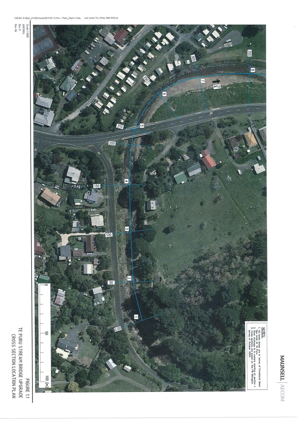
53 Doc# Page 45

54 Page 46 Doc #
55 Doc# Page 47
56 Page 48 Doc #
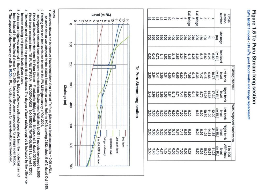
57 Doc# Page 49
58 Page 50 Doc #
59 Appendix 2 Memo WRC s bridge model File No: Z21 S200 Date: 5 December 2005 To: Mark Roper Opus Consultants Paeroa PO Box 91 Paeroa mark.roper@opus.co.nz From: Subject: Nick Martin Design soffit level and span length for replacement bridge at Te Puru BY & POST Introduction As has previously been done for the Tararu Stream, a series of one-dimensional hydraulic models have now been set up using the MIKE11 modelling software package in order to aid the design of the replacement bridge crossing the Te Puru Stream at Te Puru. A full description of the methodology used in the models will be included in the upcoming technical report for this study. However, a brief overview is contained below. Once again, the key requirement at this stage of the project is the design soffit level, as requested. The level and the various aspects considered in the derivation of this figure will also be discussed below. Methodology A basic MIKE11 model for the area had previously been set up by Environment Waikato and later reviewed and rerun by Opus Consultants (refer to your report for Transit New Zealand, ref: , September 2004). A number of small adjustments were made to reflect the comments made in that report, namely the use of the momentum equation to derive a rating for flows through the bridge (rather than using the FHWA WSPRO module within MIKE11), and a global Manning s n number of It is also important to note that new cross sections have since been obtained for this reach and have been included in the new models. These sections were surveyed in October 2004 for Environment Waikato by F.W. Millington Ltd (their ref: 2474). Docs# Page 51
 in the following locations: The entire left")
60 Using these sections as a basis, new post floodworks sections were derived to approximate the future scenario in which the bridge will be required to operate. At this stage it was assumed that this will involve floodwalls or stopbanks (at approximately the 1 in 100 year level plus a freeboard of 500 millimetres) in the following locations: The entire left bank from Ch. 0 (210 metres upstream of the bridge) onwards; & The right bank from Ch. 500 (near SH 25 at the downstream end) onwards. The approximate locations of the assumed floodworks are shown in Figure 1. Note that this diagram is for illustrative purposes only. Figure 1: Assumed approximate locations of floodworks at Te Puru As was done for the Tararu Stream case, the model s sensitivity to changes in downstream water level ( tailwater ) was tested. However, for the Te Puru Stream case, variations in tailwater had essentially no effect on levels at the bridge. Hence, the downstream level was set at a constant 2.5 metres, as per previous modelling. Environment Waikato had previously used MIKE11 s inbuilt bridge modelling modules to model flows through the bridge. However, in the Opus Consultants report for Transit New Zealand ( , September 2004) this method was highlighted as not being suitable for this application. Indeed, this method was predicting losses of around 2 metres for peak flow, which is clearly incorrect. As a result of this issue being identified, a more accurate method was developed by Tom Parsons at your Wellington offices. This method produces a rating (flow versus height) for the bridge by using the momentum equation to calculate pier losses through the bridge for a range of flows (a step hydrograph is used to simulate each flowrate in turn). This rating can then be placed into the model at the bridge (as an artificial weir module/structure in the MIKE11 network) during the design simulations. In this way, a rating was initially derived for the bridge. Once this was obtained, the design simulation was run. The simulation used a design 1 in 100 year hydrograph, the Page 52 Doc #
61 shape of which was based on flow records from the nearby Kauaeranga River, and with a 315 m 3 /s peak flow, an update which was also suggested in your September 2004 report. This was considered to be the basic design model. However, before final soffit levels could be determined it was necessary to also consider superelevation effects at the bridge. Superelevation is defined as the observed difference in stream level (between centreline and outside surface) as water flows around a bend as a result of centrifugal forces. Flows on the outside of a bend will be higher, and these effects need to be considered when determining appropriate soffit levels, especially for bridges on bends such as the Te Puru Bridge (note that the bend for this bridge is not nearly as severe as that at Tararu). The maximum superelevation level (normally during the peak flow) should be added to the modelled peak flow level to account for the elevated levels on the outer edge of the steam as flows pass beneath the bridge. An additional 100 millimetres was also added to account for an additional friction allowance, owing to uncertainties in the friction calculations through the bridge (this may be reviewed by your own hydraulics engineers in the future). Finally, a suitable freeboard level was added to allow floating debris in the stream to pass beneath the bridge without causing an obstruction. This is especially important in a steep, heavily wooded catchment such as this, where large volumes of debris are likely, and where the bridge is on a sharp bend. 1.2 metres was previously assumed to be an adequate freeboard level for the Te Puru Bridge and has been included in the calculations here. Note that, in order to gauge the future impact of climate change on the system, an additional design model was run that included a 20% increase in flows. This is in line with the accepted current practice for estimating the effects of climate change. These results are also given below. An indication of the calculated peak scour depths for the design case have also been included below and should be considered during the bridge design phase. Results The results of the modelling investigations are contained in Table 1 below. Note that future climate change may add around 400 millimetres to the soffit level requirement. The design soffit level, as requested, should therefore be taken as 10.3 metres (MSL datum). Table 1: Results of Hydraulic Modelling Investigation for Design Soffit Level at Te Puru Bridge Design Modelled Level [metres] Superelevation Allowance [metres] Additional Friction Allowance [metres] Freeboard Allowance [metres] DESIGN SOFFIT LEVEL [metres] 1 in 100 year in 100 year + 20% flows Docs# Page 53
62 For the peak scour depth calculations three calculation methods were used (Blench, Maza Alvarez & Echavarria Alfaro, and Holmes) for general scour (y ms ) and the average taken. The average peak scour depth was calculated as being 4.5 metres. For a typical peak flow depth beneath the bridge of 4.4 metres this translates to around 0.1 metres of scour. Hence, general scour can be considered minor. However, as the bridge is located on a bend in the stream, the bend scour was then calculated on top of this. Using two calculation methods (Maynord and Neill) the average bend scour was calculated as being approximately 8.4 metres (that is, potentially around 4 metres of scour at the bend). While this may seem excessive, it is not thought to be unrealistic. It is recommended that the depth of the scour beneath the bed level at the bridge is assumed to be between 3 and 5 metres. Discussion It is noted that the previous recommended soffit level of 10.1 metres has been exceeded by 0.2 metres as a result of this investigation. Additional requirements were introduced by the inclusion of the superelevation (0.25 metres) and additional friction allowances (0.10 metres), although the modelled level was slightly lower (8.78 metres compared to the previous 8.9 metres). This change in the modelled level is presumably a result of using the new surveyed cross sections and assumed stopbank/floodwall locations. As stated above, the inclusion of the friction allowance may be reviewed in the near future by yourselves. However, it is highly recommended that the superelevation allowance is maintained in the bridge s design. Conclusion Environment Waikato recommend that the minimum soffit level for the upgraded SH25 bridge crossing the Te Puru Stream at Te Puru be set at 10.3 metres. Should further information or investigations be required please do not hesitate to contact me. Yours sincerely Nick Martin Environmental Engineer River and Catchment Services Page 54 Doc #

63 Appendix 3 Docs# Erosion protection design details Page 55
64 Page 56 Doc #
65 Docs# Page 57

66 Appendix 4 Flood protection scheme design details Page 58 Doc #
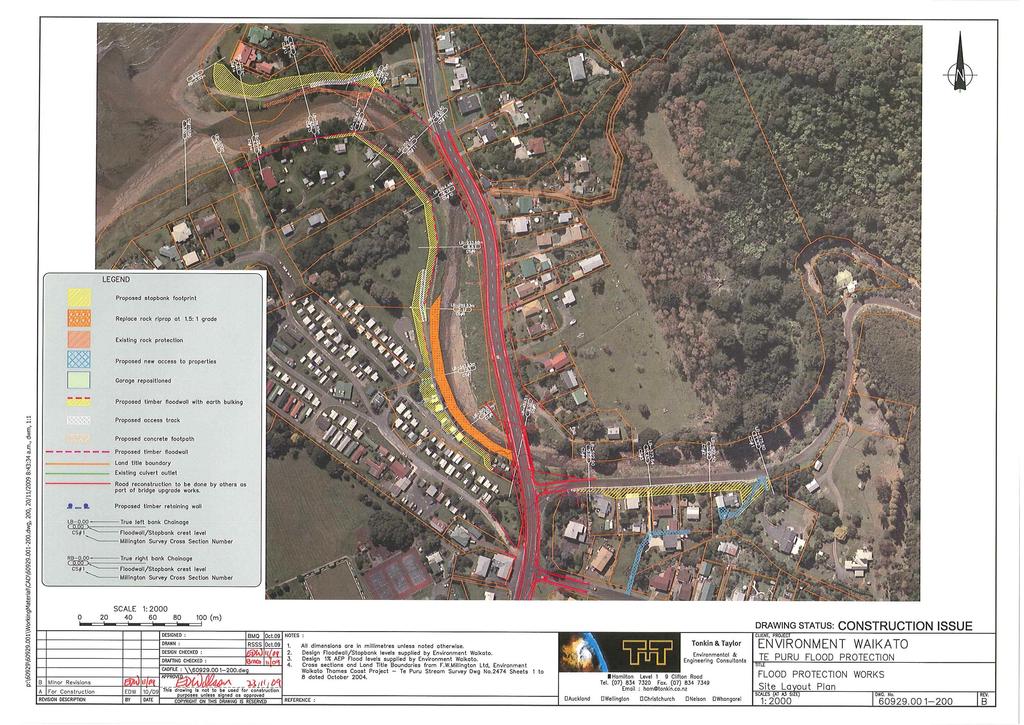
67 Docs# Page 59
68 Page 60 Doc #
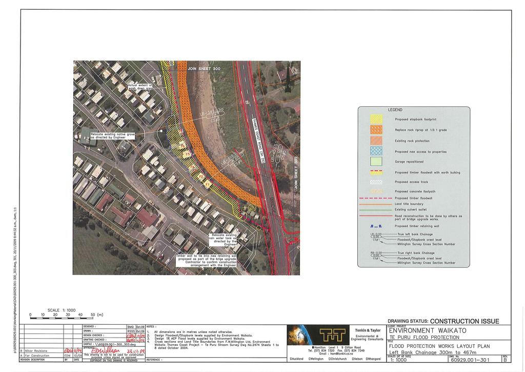
69 Docs# Page 61
70 Page 62 Doc #
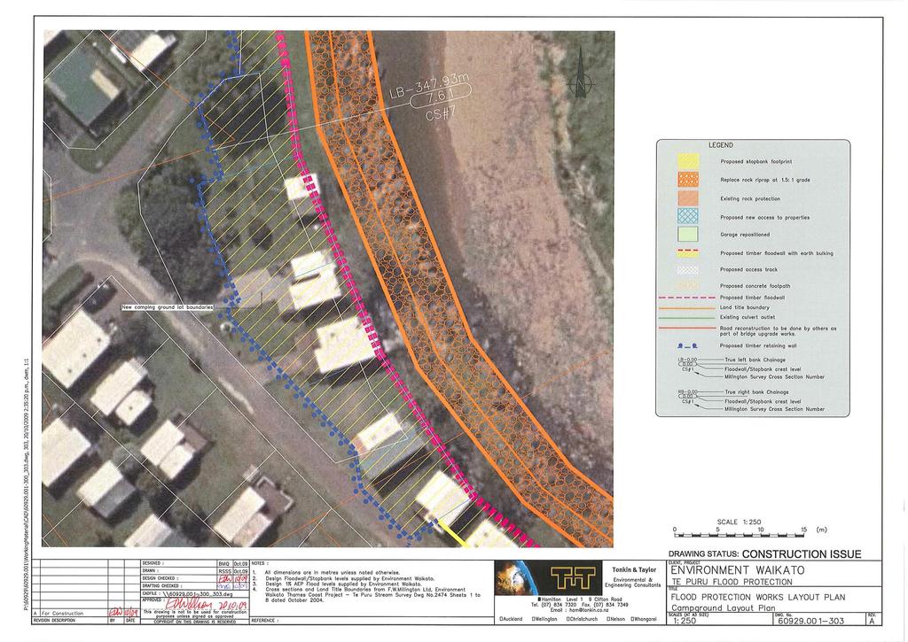
71 Docs# Page 63
72 Page 64 Doc #
73 Docs# Page 65
74 Page 66 Doc #
75 Docs# Page 67
76 Page 68 Doc #
77 Docs# Page 69
78 Page 70 Doc #
79 Docs# Page 71
80 Page 72 Doc #
81 Docs# Page 73
82 Page 74 Doc #
83 Docs# Page 75
84 Page 76 Doc #
85 Docs# Page 77

86 Page 78 Doc #
87 Docs# Page 79
88 Page 80
89 Docs# Page 81
90 TE PURU FLOOD PROTECTION SCHEME RIGHT BANK FLOOD WALL SECTION A - B Location Distance GL DCL Height CS Wall start 0 CS CS NOTE: Kingi property Fill, hence ensure foundation 2m deep Design criteria = 100Y+600mm SECTION B - C Location Distance GL DCL Height CS CS CS CS NOTE: Along SH To tie into existing footpath Design criteria = 100YCC SECTION D - E Location Distance GL DCL Height CS Keystone wall Mid-point CS High ground 68.6 NOTE: RB upstream of SH - spillway Design criteria = 100Y+300mm Page 82
91 Notes to accompany Te Puru Right Bank Floodwall Design - Wall Type A Posts: 200mm SED timber posts at 1.2m centres Heights vary (refer to long section) Planks (above ground): 167 x 45 mm timber tongue and groove (ex 200 x 50). Every second plank anchored with 12 mm hot dip galvanised engineers bolts with square washers. Remaining planks to be nailed. Tongue and groove planks to extend one board (minimum) below existing ground level. Planks (below ground): Capping board: (where applicable) 200 x 25 mm rough sawn timber. Three rough sawn timber planks to start below tongue and groove timber, which extends one board (minimum) below existing ground level. Planks to be nailed. 250 x 50 mm nailed to each post and to the top plank at 200 mm centres. Foundation (below ground): Excavated to a minimum depth of 1.7m 100 mm thick concrete punch pad Trench backfilled with compacted clay. Foundation (ground level): Timber treatment: Concrete: Drawing key: Stream side x 100 mm concrete mowing strip flush with final ground level Land side x 400mm concrete pad flush with final ground level, including steel reinforcement (two 12mm diameter reinforcing bars stapled to each post with a cover of 100mm and vertical spacing of 200mm). H4 planks, H5 posts 17.5 MPa Concrete Existing ground Timber 29/09/10: First draft (for review by RP Spooner) 14/03/11: First draft (for review by RP Spooner and DJ Shilton) 24/03/11: Final Te Puru Flood Protection Scheme Right Bank Floodwall - Design Type A 1: Z21 F200 / of 4 Docs# Page 83
92 1700mm 800 min Varies (refer to long section) Existing Ground Level Front Elevation (river) mm thick concrete punch pad Side Elevation Rear Elevation (land) 29/09/10: First draft (for review by RP Spooner) 14/03/11: First draft (for review by RP Spooner and DJ Shilton) 24/03/11: Final Te Puru Flood Protection Scheme Right Bank Floodwall - Design Type A 1: Z21 F200 / of 4 Page 84 Doc #
93 Notes to accompany Te Puru Right Bank Floodwall Design - Wall Type B Posts: 150mm SED timber posts at 1.5 m centres Heights vary (refer to long section) Planks (above ground): 167 x 45 mm timber tongue and groove (ex 200 x 50). Every second plank anchored with 12 mm hot dip galvanised engineers bolts with square washers. Remaining planks to be nailed. Tongue and groove planks to extend one board (minimum) below existing ground level. Planks (below ground): Capping board: (where applicable) 200 x 25 mm rough sawn timber. Three rough sawn timber planks to start below tongue and groove timber, which extends one board (minimum) below existing ground level. Reduced to two rough sawn planks where wall height above ground is less than 0.6m. Planks to be nailed. 200 x 50 mm nailed to each post and to the top plank at 200 mm centres. Foundation (below ground): Excavated to a minimum depth of 0.9 m for wall height above ground 0.6 m Excavated to a minimum depth of 1.0 m for wall height above ground: 0.6 m < wall height < 1.0 m Excavated to a minimum depth of 1.2m for wall height above ground 1.0 m Trench backfilled with compacted clay. Foundation (ground level): Timber treatment: Concrete: Drawing key: Stream side x 100 mm concrete mowing strip flush with existing ground level where sufficient room. Land side - B to C: Floodwall to be constructed against existing footpath. D to E: 300 x 400mm concrete pad flush with final ground level, including steel reinforcement (two 12mm diameter reinforcing bars stapled to each post with a cover of 100mm and vertical spacing of 200mm). H4 planks, H5 posts 17.5 MPa Concrete Existing ground Timber 29/09/10: First draft (for review by RP Spooner) 14/03/11: Second draft (for review by RP Spooner and DJ Shilton) 24/03/11: Final Te Puru Flood Protection Scheme Right Bank Floodwall Design - Type B 1:20 Z21 F200 / of 4 Docs# Page 85
94 800 min Varies (refer to notes) Varies (refer to long section) Existing Ground Level Front Elevation (river) Side Elevation Rear Elevation (land) 29/09/10: First draft (for review by RP Spooner) 14/03/11: Second draft (for review by RP Spooner and DJ Shilton) 24/03/11: Final Te Puru Flood Protection Scheme Right Bank Floodwall Design - Type B 1:20 Z21 F200 / of 4 Page 86 Doc #
 Docs#3116998 Page")
95 Proposed flood wall extension (130m long) Docs# Page 87

96 Page 88 Doc #
97 Appendix 5 Secondary overland flowpath arrangement Docs# Page 89
98 Page 90 Doc #
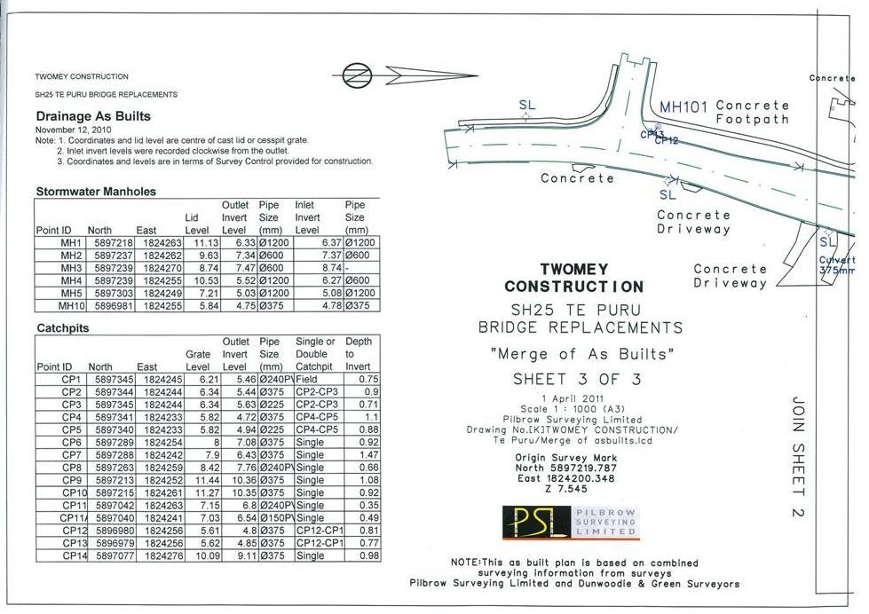
99 Docs# Page 91

100 Appendix 6 Bridge upgrade design drawings Page 92 Doc #
101 Docs# Page 93
102 Page 94 Doc #
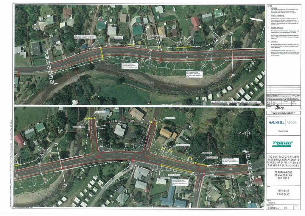
103 Docs# Page 95

104 Page 96 Doc #
105 Appendix 7 As-built survey Docs# Page 97

106 Page 98 Doc #
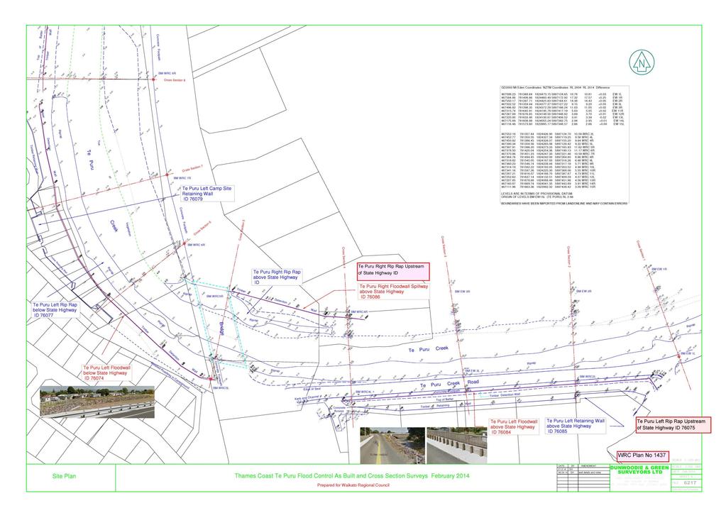
107 Docs# Page 99
Flood Hazard Assessment of Potential Growth Areas Palmerston North City: Ashhurst
 Flood Hazard Assessment of Potential Growth Areas Palmerston North City: Ashhurst Report prepared for Palmerston North City Council by Philip Wallace River Edge Consulting Limited May 2013 Table of Contents
Hydraulic Capacity Review of the Waioho Stream and Canal
 Hydraulic Capacity Review of the Waioho Stream and Canal Prepared by Ingrid Pak, Environmental Engineer Environment Bay of Plenty October 2006 5 Quay Street P O Box 364 Whakatane NEW ZEALAND ISSN 1176-5550
NOT-MODELLING FOR STORMWATER AROUND THE KAIKOURA ALLUVIAL FANS
 NOT-MODELLING FOR STORMWATER AROUND THE KAIKOURA ALLUVIAL FANS Mark Pennington Pattle Delamore Partners Limited, Kaikoura, New Zealand ABSTRACT The Kaikoura plains are formed by a process of coalescing
Northland Regional Council. Awanui Flood Scheme Preliminary Design
 REPORT Northland Regional Council Awanui Flood Scheme Preliminary Design REPORT Northland Regional Council Awanui Flood Scheme Preliminary Design Report prepared for: NORTHLAND REGIONAL COUNCIL Report
14 NATURAL HAZARDS Background Resource Management Issues
 14 NATURAL HAZARDS 14.1 Background The particular geology, hydrology and topography of the Hutt Valley make Upper Hutt vulnerable to a variety of natural hazards. Earthquakes and flooding are the most
Hydraulic Capacity Review Rangitaiki River and Reids Floodway
 Hydraulic Capacity Review Rangitaiki River and Reids Floodway February 2011 Contents Executive Summary... 1 1 Introduction... 2 2 Hydrology and Sea Levels... 2 2.1 Design Hydrographs... 2 2.2 Sea Level...
14 NATURAL HAZARDS Background Resource Management Issues
 14 NATURAL HAZARDS 14.1 Background The particular geology, hydrology and topography of the Hutt Valley make Upper Hutt vulnerable to a variety of natural hazards. Earthquakes and flooding are the most
3.5 Hydrology & Hydraulics
 3.5 Hydrology & Hydraulics 3.5.1 Purpose The purpose of this section is to provide results from the analysis and assessment of the impact of the proposed Carmichael Rail Alignment (Option 11 Revision 1)
Pakenham East Precinct Structure Plan. Deep Creek Corridor Proposals
 Hydrological and Environmental Engineering Pakenham East Precinct Structure Plan Deep Creek Corridor Proposals 5 October 2014 Report by: Valerie Mag BE Civil (Hons), M Eng Sci Stormy Water Solutions stormywater@optusnet.com.au
Effects on Flood Levels from the Proposed Whakatane Marina
 Effects on Flood Levels from the Proposed Whakatane Marina Peter West, Graduate Engineer Environment Bay of Plenty September 2004 5 Quay Street P O Box 364 Whakatane NEW ZEALAND ISSN 1176-5550 Working
14 NATURAL HAZARDS Background Resource Management Issues
 14 NATURAL HAZARDS 14.1 Background The particular geology, hydrology and topography of the Hutt Valley make Upper Hutt vulnerable to a variety of natural hazards. Earthquakes and flooding are the most
Application for resource consent Form B Damming and diversion of water
 Application for resource consent Form B Damming and diversion of water Notes Resource use activities must meet all the conditions of any relevant Permitted Activity Rules in the Waikato Regional Plan or
498 AVE BRIDGE HYDRAULICS INVESTIGATION OF IMPACTS RELATED TO TOWN OF HIGH RIVER FLOOD MITIGATION WORKS
 498 AVE BRIDGE HYDRAULICS INVESTIGATION OF IMPACTS RELATED TO TOWN OF HIGH RIVER FLOOD MITIGATION WORKS Submitted to: M.D. of Foothills No. 31 High River, Alberta Submitted by: Amec Foster Wheeler Environment
The approach to managing natural hazards in this Plan is to: set out a clear regional framework for natural hazard management,
 9 Natural Hazards 9.1 Scope and Background This chapter establishes an overall framework for natural hazard management under the RMA. It also sets out the division of responsibilities between the Regional
FORM B: DAMMING AND DIVERSION OF WATER
 APPLICATION FOR RESOURCE CONSENT FORM B: DAMMING AND DIVERSION OF WATER NOTES Resource use activities must meet all the conditions of any relevant Permitted Activity Rules in the Waikato Regional Plan
Hydrotechnical Design Guidelines for Stream Crossings
 Hydrotechnical Design Guidelines for Stream Crossings Introduction Design of stream crossings and other in-stream highway facilities requires estimation of design highwater elevation and mean channel velocity.
PART 5D - NATURAL HAZARDS
 CONTENTS...PAGE 5D.1 CONTENT AND STRUCTURE...3 5D.2 RESOURCE MANAGEMENT ISSUES...3 5D.3 RESOURCE MANAGEMENT OBJECTIVE AND POLICIES...4 5D.4 RESOURCE MANAGEMENT STRATEGY...4 5D.5 IMPLEMENTATION...4 5D.6.RULES
Bridge Planning Updates. Bridge Planning Practitioners Workshop April 2012
 Bridge Planning Updates Bridge Planning Practitioners Workshop April 2012 Bridge Website Bridge Website Bridge Website Bridge Website BPG 11 Stormwater Management at Rural Bridges Released July 2010 Documents
7. NATURAL HAZARDS 7.1 SECTION INTRODUCTION
 7. NATURAL HAZARDS 7.1 SECTION INTRODUCTION 7.1.1 The Resource Management Act empowers Council to control any actual or potential effects of the use, development, or protection of land for the purpose
This chapter describes the potential hydrological effects of the Project in terms of:
 19. Hydrology Overview The Project will result in changes to existing hydrology from land use changes and from changes to stream morphology. Hydrological and hydraulic modelling has been undertaken to
TULLAMORE FLOOD RISK ASSESSMENT AND MANAGEMENT STUDY
 TULLAMORE FLOOD RISK ASSESSMENT AND MANAGEMENT STUDY FINAL HYDRAULICS REPORT 1794/RP/004/C June 2008 FRAM Section Engineering Services Office of Public Works Doc. No. 1794/RP/004/C ii June 2008 INDEX OF
A part of BMT in Energy and Environment Kosciusko Avenue Main Drain Catchment Drainage / Flood Study Draft Report
 A part of BMT in Energy and Environment Kosciusko Avenue Main Drain Catchment Drainage / Flood Study Draft Report R.M7299.003.00.DraftReport January 2011 Kosciusko Avenue Main Drain Catchment Drainage
Armstrong Creek West Precinct. Review of Stormwater Management Strategy
 Armstrong Creek West Precinct Review of Stormwater Management Strategy 31 October 2011 Report by: Valerie Mag, B.E. Civil (Hons), M. Eng. Sci. Stormy Water Solutions stormywater@optusnet.com.au Ph 9511
LAKE COUNTY HYDROLOGY DESIGN STANDARDS
 LAKE COUNTY HYDROLOGY DESIGN STANDARDS Lake County Department of Public Works Water Resources Division 255 N. Forbes Street Lakeport, CA 95453 (707)263-2341 Adopted June 22, 1999 These Standards provide
Part 8 Natural hazards
 Part 8 Natural hazards Contents Page 8.1 Introduction... 3 8.2 Resource management issue... 3 8.3 Objectives and policies... 3 8.4 Resource management strategy... 5 8.5 Rules - restricted discretionary
Appendix D Flood Assessment
 Appendix D Flood Assessment Mount Pleasant Operation Rail Modification Flood Assessment MACH Energy Australia Pty Ltd 0744-09-B3, 19 December 2017 Report Title Client Report Number Mount Pleasant Operation
SECTION 6 STORMWATER AND LAND DRAINAGE
 SECTION 6 STORMWATER AND LAND DRAINAGE Final Version, Approved September 2003 Section 6 and Land Drainage Contents 6.1 PERFORMANCE STANDARDS... 2 6.1.1 General... 2 6.2 MEANS OF COMPLIANCE... 3 6.2.1 General...
4.0 STORMWATER CONTENTS. Section 4 Stormwater
 4.0 STORMWATER CONTENTS 4.0 STORMWATER... I 4.1 Introduction... 4-1 4.1.1 Objectives... 4-1 4.1.2 Stormwater Management Hierarchy... 4-1 4.1.3 Level of Service... 4-2 4.1.4 Alteration to Existing Infrastructure...
REPORT Chapman Tripp on behalf of the Earthquake Commission (EQC)
") REPORT Chapman Tripp on behalf of the Earthquake Commission (EQC) Canterbury Earthquake Sequence: Increased Flooding Vulnerability River Modelling and Coastal Extensions Report REPORT Chapman Tripp on
REPORT Chapman Tripp on behalf of the Earthquake Commission (EQC) Canterbury Earthquake Sequence: Increased Flooding Vulnerability River Modelling and Coastal Extensions Report REPORT Chapman Tripp on
Waiohine FMP - Flood Modelling and Mapping Audit
 Report Waiohine FMP - Flood Modelling and Mapping Audit Prepared for Greater Wellington Regional Council Prepared by Beca Ltd (Beca) 9 May 2017 Revision History Revision Nº Prepared By Description Date
WDC FMS. Whangarei CBD Flood Management Study. Flood Damage Assessment REPORT. Whangarei District Council. Prepared for.
 REPORT WDC FMS Whangarei CBD Flood Management Study Flood Damage Assessment Prepared for Whangarei District Council Private Bag 9023 Whangarei 13 September 2006 42744310/FLOOD DAMAGES REPORT - FINAL Project
Temporary Watercourse Crossing: Culverts
 Temporary Watercourse Crossing: Culverts DRAINAGE CONTROL TECHNIQUE Low Gradient Velocity Control Short Term Steep Gradient Channel Lining Medium-Long Term Outlet Control Soil Treatment Permanent Symbol
Review of the Flood Carrying Capacity of the Tarawera River below State Highway 30
 Review of the Flood Carrying Capacity of the Tarawera River below State Highway 30 Prepared by Verna Arts, Engineering Hydrologist Environment Bay of Plenty April 2005 5 Quay Street P O Box 364 Whakatane
Appendix D. Flood Study Report
 Appendix D Flood Study Report New Hope Coal Horse Creek Base Case (Natural Conditions) and Diversion Flood Study for Elimatta Mine 28 March 2014 Contents Page number 1. Introduction 1 1.1 Background 1
Appendix E: Bridge Site Information Summary
 BRIDGE MANUAL E - 1 APPENDIX E: BRIDGE SITE INFORMATION SUMMARY Appendix E: Bridge Site Information Summary Table of Contents Notes..E 3 Section 1: Basic Information..E 4 Section 2: River Data..E 8 Section
A part of BMT in Energy and Environment Portarlington East Drainage / Flood Study Final Report
 A part of BMT in Energy and Environment S Portarlington East Drainage / Flood Study Final Report R.M7373.003.02.FinalReport October 2009 Portarlington East Drainage/Flood Study Final Report Prepared For:
SH3 Awakino Tunnel Bypass. Assessment of Environmental Effects Stormwater
 SH3 Awakino Tunnel Bypass Assessment of Environmental Effects Stormwater i Contents Executive Summary... a 1 Introduction... 1 2 Description of Project, Key Features and Constraints... 1 3 Assessment
Prepared for: City of Jeffersonville. November Prepared by
 JEFFERSONVILLE STORMWATER MASTER PLAN HYDRAULICS APPENDIX JEFFERSONVILLE, INDIANA Prepared for: City of Jeffersonville November 2011 Prepared by Christopher B. Burke Engineering, Ltd. 115 W. Washington
Flood extents for 1% and 2% AEP floods and potential mitigation measures for 1% AEP flood extents at Westport based on LiDAR
 Flood extents for 1% and 2% AEP floods and potential mitigation measures for 1% AEP flood extents at Westport based on LiDAR NIWA Client Report: CHC2010-079 June 2010 NIWA Project: WCR10501 Flood extents
Storm water Catchment Analysis
 Storm water Catchment Analysis Analysis index 1. Storm water attenuation tank sizing method 2. Consent notices for storm water attenuation tanks 3. Summary of sub catchments 4. Hydrological Analysis for
H28. Special Purpose Quarry Zone
 H28. Special Purpose Quarry Zone H28.1. Zone description Mineral resources are important to Auckland s economy and development. The Special Purpose Quarry Zone provides for significant mineral extraction
DRAINAGE REVIEW: Berwick Health and Education Precinct. for. Victorian Planning Authority
 DRAINAGE REVIEW: Berwick Health and Education Precinct for Victorian Planning Authority April 2017 Document history Revision: Revision no. 03 Author/s Jonathon McLean Approved Jonathon McLean Distribution:
Appendix C, Attachment 4 June 11, Diversion Channel Outlet Hydraulic Modeling RAS and ADH
 Diversion Channel Outlet Hydraulic Modeling RAS and ADH 11 June 2012 1 Contents Introduction... 3 HEC-RAS modeling of Outlet... 3 Transition Structure Geometry... 3 ADH Modeling of Outlet and Floodplain...
SCOUR AT COMPLEX BRIDGE STRUCTURES THE BENEFITS OF TWO-DIMENSIONAL HYDRAULIC MODELLING IN THE ESTIMATION OF SCOUR DEPTHS
 SCOUR AT COMPLEX BRIDGE STRUCTURES THE BENEFITS OF TWO-DIMENSIONAL HYDRAULIC MODELLING IN THE ESTIMATION OF SCOUR DEPTHS M Burgess 1, C Moore 1 1 Arup, Sydney, NSW Abstract Assessing scour potential at
Natural Hazards Natural Hazards Explanatory Statement Significant Issues Objectives and Policies...
 Section Contents Natural Hazards... 2 8. Natural Hazards... 2 Explanatory Statement... 2 8.1 Significant Issues... 3 8.2 Objectives and Policies... 3 8.3 Activity Lists... 4 8.4 Matters of Control... 7
TECHNICAL GUIDANCE and CASE STUDY for INEFFECTIVE FLOW and CONVEYANCE SHADOW AREAS
 Utilities electric stormwater wastewater water 700 Wood St. PO Box 580 Fort Collins, CO 80522 970.221.6700 970.221.6619 fax 970.224.6003 TDD utilities@fcgov.com fcgov.com/utilities TECHNICAL GUIDANCE and
The natural hazard types that have been identified within the City include the following:
 Chapter 62 NATURAL HAZARDS 62.1 INTRODUCTION Napier City, like many other cities within New Zealand, is subject to the effects of natural hazards. Since the enactment of the Resource Management Act, the
Technical Memorandum No. 8 June 3, 2013 Page 2. FEMA Floodplain Mapping Flood Elevations at WWTP
 Page 2 FEMA Floodplain Mapping Flood Elevations at WWTP Existing Flood Control Facilities The City of Davis WWTP is located immediately north of the Willow Slough Bypass and west of the Yolo Bypass (see
Chapter 6. The Empirical version of the Rational Method
 Chapter 6 The Empirical version of the Rational Method The Empirical version is named because the parameters it uses (apart from rainfall data) are arbitrary and are generally based on experience or observation
Opanuku Stream Accuracy Benchmark 1. Introduction
 Opanuku Stream Accuracy Benchmark 1. Introduction 1.1 Fundamental Approach The proposed approach to flood model accuracy assessment uses data directly measured during an actual physical flood event. In
10(a) Bridge and culvert design information
 Bridge and culvert design information") 10(a) Bridge and culvert design information The following information is required to accompany resource consent applications for bridges or culverts on waterways. Please answer all questions if possible.
10(a) Bridge and culvert design information The following information is required to accompany resource consent applications for bridges or culverts on waterways. Please answer all questions if possible.
Auckland Region climate change projections and impacts: Summary Report
 Auckland Region climate change projections and impacts: Summary Report Revised January 2018 Key projections for the Auckland CBD Warming of the climate is unequivocal, with temperature increases already
STATEMENT OF EVIDENCE OF PETER BLACKWOOD
 STATEMENT OF EVIDENCE OF PETER BLACKWOOD PALMERSTON NORTH CITY COUNCIL - PROPOSED PLAN CHANGE 15H: AIRPORT ZONE 1. Thank you for the opportunity to present evidence in support of Horizons Regional Council
CLAY STREET BRIDGE REPLACEMENT
 HYDROLOGY /HYDRAULICS REPORT. EL DORADO COUNTY CLAY STREET BRIDGE REPLACEMENT Prepared by: Joseph Domenichelli Domenichelli & Associates 1107 Investment Blvd., Suite 145 El Dorado Hills, California 95762
Hydraulic and Sediment Transport Modeling Strategy
 Appendix B Hydraulic and Sediment Transport May 2014 Technical Memorandum Channel Capacity Report September 2014 San Joaquin River Restoration Program Hydraulic and Sediment Transport The San Joaquin River
Title Advanced Hydraulic Modeling to Support Emergency Action Plans
 Title Advanced Hydraulic Modeling to Support Emergency Action Plans Abstract Freese and Nichols, Inc. (FNI) developed an Emergency Action Plan (EAP) for a Levee Improvement District (LID) located in a
Stormwater Management Studies PDS Engineering Services Division ES Policy # 3-01
 Stormwater Management Studies PDS Engineering Services Division Revised Date: 2/28/08 INTRODUCTION The City of Overland Park requires submission of a stormwater management study as part of the development
E36. Natural hazards and flooding
 E36. Natural hazards and flooding E36.1. Background Auckland is affected by natural hazards including: those that occur frequently such as flooding, coastal erosion (including the effects of sea level
Successful performance of detention dams in the February 2004 Manawatu floods Don Tate 1
 Abstract Successful performance of detention dams in the February 2004 Manawatu floods Don Tate 1 The Manawatu floods of February 2004 were an extreme event, causing widespread damage over a wide area.
THE EFFECTS OF URBANIZATION ON THE MINGO CREEK WATERSHED
 THE EFFECTS OF URBANIZATION ON THE MINGO CREEK WATERSHED by Tim Marshall (presented at the Sixth Conference on Hydrometeorology in Indianapolis, IN, 1984) 1. INTRODUCTION Urbanization of flood plains presents
Lower San Joaquin River Feasibility Study PLAN FORMULATION ADDENDUM
 PLAN FORMULATION ADDENDUM Non-Structural Measure Descriptions Elevate Critical Infrastructure This measure would raise at-risk critical structures above the design inundation level. Elevation would be
E36. Natural hazards and flooding
 E36. Natural hazards and flooding E36.1. Background Auckland is affected by natural hazards including: those that occur frequently such as flooding, coastal erosion (including the effects of sea level
LOCATION AND DESIGN DIVISION
 VIRGINIA DEPARTMENT OF TRANSPORTATION LOCATION AND DESIGN DIVISION INSTRUCTIONAL AND INFORMATIONAL MEMORANDUM GENERAL SUBJECT: CULVERT DESIGN SPECIFIC SUBJECT: COUNTERSINKING AND LOW FLOW CONSIDERATIONS
8 MANAGING THE EFFECTS OF NATURAL HAZARDS
 8 MANAGING THE EFFECTS OF NATURAL HAZARDS 8.1 RESOURCE MANAGEMENT ACT OBLIGATIONS 8.1.1 A natural hazard is defined under Section 2 as being Any atmospheric or earth or water related occurrence (including
Developing a local flood risk management strategy Annex 1: Flooding, flood sources and flood defences
 Developing a local flood risk management strategy Annex 1: Flooding, flood sources and flood defences Pennine Water Group, University of Sheffield in collaboration with the partners of the FloodResilienCity
E36. Natural hazards and flooding
 E36. Natural hazards and flooding E36.1. Background Auckland is affected by natural hazards including: those that occur frequently such as flooding, coastal erosion (including the effects of sea level
Highway Drainage 1- Storm Frequency and Runoff 1.1- Runoff Determination
 Highway Drainage Proper drainage is a very important consideration in design of a highway. Inadequate drainage facilities can lead to premature deterioration of the highway and the development of adverse
UPDATE OF ARC TP108 RUN-OFF CALCULATION GUIDELINE
 UPDATE OF ARC TP108 RUN-OFF CALCULATION GUIDELINE Bodo Hellberg, Stormwater Action Team, Auckland Regional Council Matthew Davis, Stormwater Action Team, Auckland Regional Council ABSTRACT This paper focuses
Te Mania Sub-Catchment Action Plan
 Te Mania Sub-Catchment Action Plan 2012 The Te Mania Sub-Catchment Action Plan is one of a series produced for the sub-catchments surrounding the Tauranga Harbour. The aim of this action plan is to provide
An Overview of Natural Hazards in the Hauraki District
 Environment Waikato Technical Report 2006/16 An Overview of Natural Hazards in the Hauraki District Including a qualitative risk assessment Prepared by: Adam Munro For: Environment Waikato PO Box 4010
An Overview of Natural Hazards in the Hauraki District
 Environment Waikato Technical Report 2006/16 An Overview of Natural Hazards in the Hauraki District Including a qualitative risk assessment Prepared by: Adam Munro For: Environment Waikato PO Box 4010
STORM WATER MANAGEMENT REPORT
 Silvercreek Junction STORM WATER MANAGEMENT REPORT Howitt Creek at the Silvercreek Parkway Site Guelph, Ontario August, 2008 TSH File 22304A-04 August 19, 2008 STORMWATER MANAGEMENT REPORT Howitt Creek
IDENTIFYING FLOOD CONTROL LOTS IN THE HORNSBY LGA
 IDENTIFYING FLOOD CONTROL LOTS IN THE HORNSBY LGA B.C. Phillips 1, R.S. Thomson 1, T. Fang 1, S. Yu 1, A. Boyd 2 1 Cardno (NSW/ACT) Pty Ltd, Sydney, NSW 2 Hornsby Shire Council, Hornsby, NSW Introduction
Peer review of Taupō District flood hazard reports. Prepared for Taupō District Council
 Peer review of Taupō District flood hazard reports Prepared for Taupō District Council March 2015 Prepared by: Mr Roddy Henderson Mr Maurice Duncan Dr Murray Hicks For any information regarding this report
NRC 1988: Coastal Hazard Identification. Whangarei County. Technical Publication No.1988/1, March 1988, held by Northland Regional Council.
 56 Natural Hazards 56.1 Introduction This Chapter contains rules relating to land uses in areas mapped as hazard areas. These areas are shown on the Planning Maps by shading on the Resource Area Maps.
Floodplain Special Review
 Larimer County Engineering Dept. Procedural Guide for: August 1, 2007 Floodplain Special Review Floodplain Special Review Process The floodplain special review process contains the following steps: 1.
This summary and the Report subsequently inform the recommended mitigation contained in Section 28 and will inform the Project conditions.
 18. Air The Project Air quality team prepared an Air Quality Assessment Report for the Project, which is included in Volume 3 (Part 1). The Report provides an assessment of air quality effects associated
Brisbane River Catchment Flood Study overview
 Brisbane River Catchment Flood Study overview Brisbane River Catchment Flood Study overview Floods can and do occur in the Brisbane River catchment. The Queensland Government, local councils and the community
UPDATE 3A MINIMUM REQUIREMENTS
 3. STORMWATER CONTENTS SECTION PAGE LATEST UPDATE 3A MINIMUM REQUIREMENTS 3.1 July 2004 3B MEANS OF COMPLIANCE 3.1 July 2004 3.B.1 DESIGN STANDARD 3.1 October 2005 3.B.2 DISCHARGE PERMITS 3.3 July 2004
Upstream structural management measures for an urban area flooding in Turkey
 doi:10.5194/piahs-370-45-2015 Author(s) 2015. CC Attribution 3.0 License. Upstream structural management measures for an urban area flooding in Turkey Z. Akyurek 1, B. Bozoğlu 1, S. Sürer 2, and H. Mumcu
OFFICE OF STRUCTURES MANUAL FOR HYDROLOGIC AND HYDRAULIC DESIGN CHAPTER 19 CONSTRUCTION GUIDELINES
 OFFICE OF STRUCTURES MANUAL FOR HYDROLOGIC AND HYDRAULIC DESIGN CHAPTER 19 CONSTRUCTION GUIDELINES APRIL 2011 MANUAL FOR HYDROLOGIC AND HYDRAULIC DESIGN CHAPTER 19 - CONSTRUCTION GUIDELINES TABLE OF CONTENTS
Waitarere Beach Road Curves Project Erosion and Sediment Control Plan
 APPENDIX D Waitarere Beach Road Curves Project Prepared for The New Zealand Transport Agency November 2015 QUALITY STATEMENT PROJECT MANAGER Jon England PROJECT TECHNICAL LEAD Phil Peet PREPARED BY Stephen
INTEGRATED FLOOD MANAGEMENT IN SAMOA
 INTEGRATED FLOOD MANAGEMENT IN SAMOA From Science to Policy Amataga Penaia 1, Ausetalia Titimaea 1, Jude Kohlhase 1, Filomena Nelson 1, Netatua Pelesikoti 2, Michael Bonte-Grapentin 2, Litea Biukoto 2,
The hydrologic and hydraulic study of the behaviour of the Nyl River floodplain
 River Basin Management IV 149 The hydrologic and hydraulic study of the behaviour of the Nyl River floodplain C. F. B. Havenga 1, A. Jeleni 1, W. V. Pitman 2 & A. K. Bailey 2 1 Department of Water Affairs
A Hydrologic Study of the. Ryerson Creek Watershed
 A Hydrologic Study of the Ryerson Creek Watershed Dave Fongers Hydrologic Studies Unit Land and Water Management Division Michigan Department of Environmental Quality May 8, 2002 Table of Contents Summary...2
TABLE OF CONTENTS PART III - MINIMUM DESIGN STANDARDS Section 105 DRAINAGE SYSTEM DESIGN SPECIFICATIONS AND SCOPE 105.1
 TABLE OF CONTENTS PART III - MINIMUM DESIGN STANDARDS Section 105 DRAINAGE SYSTEM DESIGN SECTION TITLE PAGE 105.1. SPECIFICATIONS AND SCOPE 105.1 105.2. METHODS OF ANALYSIS 105.1 105.2.1. Rational Method
Flow Diversion Banks: General
 Flow Diversion Banks: General DRAINAGE CONTROL TECHNIQUE Low Gradient Velocity Control Short Term Steep Gradient Channel Lining Medium-Long Term Outlet Control Soil Treatment Permanent [1] [1] Flow diversion
FLOOD RESILIENCE STUDY FOR MITHI RIVER CATCHMENT IN MUMBAI, INDIA
 International Conference on Flood Resilience: FLOOD RESILIENCE STUDY FOR MITHI RIVER CATCHMENT IN MUMBAI, INDIA Vinay Nikam 1, Kapil Gupta 1,* 1 Indian Institute of Technology Bombay, Mumbai, India * Department
TABLE OF CONTENTS. 1.0 Background Watershed Description Hydrology - HEC-HMS Models Hydraulics - HEC-RAS Models...
 TABLE OF CONTENTS 1.0 Background... 1 2.0 Watershed Description... 1 3.0 Hydrology - HEC-HMS Models... 2 3.1 Hydrologic Approach... 2 3.2 Drainage Areas... 2 3.3 Curve Numbers... 2 3.4 Lag Times... 3 3.5
DRAINAGE & DESIGN OF DRAINAGE SYSTEM
 Drainage on Highways DRAINAGE & DESIGN OF DRAINAGE SYSTEM P. R.D. Fernando Chartered Engineer B.Sc.(Hons), M.Eng. C.Eng., MIE(SL) Drainage Requirement of Highway Drainage System Introduction Drainage means
AMENDMENT. Section 3.5 and 3.6 Flood Hazard Area Land Use Management Guidelines
 AMENDMENT Section 3.5 and 3.6 Flood Hazard Area Land Use Management Guidelines 3.5 The Sea 3.5.1 Background and Reference Documents The content for this Amendment is drawn primarily from, Climate Change
Isle of Wight Strategic Flood Risk Assessment MK2. Appendix E West Wight
 Isle of Wight Strategic Flood Risk Assessment MK2 Appendix E June 2010 Isle of Wight Strategic Flood Risk Assessment Overview The RDA is comprised of the towns of Totland and Freshwater and is classified
RETENTION BASIN EXAMPLE
 -7 Given: Total Tributary Area = 7.5 ac o Tributary Area within Existing R/W = 5.8 ac o Tributary Area, Impervious, Outside of R/W = 0.0 ac o Tributary Area, Pervious, Outside of R/W = 1.7 ac o Tributary
Low Gradient Velocity Control Short Term Steep Gradient Channel Lining Medium-Long Term Outlet Control Soil Treatment Permanent [1]
![Low Gradient Velocity Control Short Term Steep Gradient Channel Lining Medium-Long Term Outlet Control Soil Treatment Permanent [1]](/thumbs/83/88729038.jpg "Low Gradient Velocity Control Short Term Steep Gradient Channel Lining Medium-Long Term Outlet Control Soil Treatment Permanent [1]") Diversion Channels DRAINAGE CONTROL TECHNIQUE Low Gradient Velocity Control Short Term Steep Gradient Channel Lining Medium-Long Term Outlet Control Soil Treatment Permanent [1] [1] The design of permanent
Diversion Channels DRAINAGE CONTROL TECHNIQUE Low Gradient Velocity Control Short Term Steep Gradient Channel Lining Medium-Long Term Outlet Control Soil Treatment Permanent [1] [1] The design of permanent
FLOOD CHARACTERISTICS
 simple yet widely accepted modeling approach that uses a constant flow to represent a flooding event, and it is currently the most common tool used for FIS efforts. Modeling for the FM Diversion project
Hydrological and Hydraulic Guidelines
 Hydrological and Hydraulic Guidelines Prepared by Environmental Hazards Group Bay of Plenty Regional Council Guideline 2012/02 5 Quay Street PO Box 364 Whakatane NEW ZEALAND ISSN: 1179-9595 (Print) ISSN:
Stage 3: Flood Study Report DRAFT
 hydrol Stage 3: Flood Study Report DRAFT Dee Why South Catchment Flood Study W4961 W4961 Prepared for 29 April 2013 Document Information Prepared for Project Name File Reference R001 Stage 3 Flood Study
The District Council and the Regional Council both have functions for avoiding or mitigating natural hazard events in the District.
 8. Natural Hazards 8.1 Introduction Natural hazard events include earthquakes, snow, tsunami, erosion, volcanic and geothermal activity, land subsidence, sedimentation, wind, drought, fire, or flooding
The Lower Watershed Ecosystem Services in Coastal Areas with a focus on the Courtenay River Floodplain
 The Lower Watershed Ecosystem Services in Coastal Areas with a focus on the Courtenay River Floodplain Jennifer Sutherst Estuary Coordinator and Staff Biologist Comox Valley Project Watershed Society Lower
CHAPTER 7. San Dieguito River Flooding Adaptation
 CHAPTER 7 San Dieguito River Flooding Adaptation This chapter includes a range of adaptation measures to address vulnerabilities from flooding along the San Dieguito River, including the river valley,