Blackburn Grounding Systems
|
|
|
- Naomi Ford
- 6 years ago
- Views:
Transcription


1 In this section... Blackburn Grounding Systems Blackburn Grounding Systems Overview... F-252 E-Z-Ground Grounding Connectors...F-25 F-268 Cast Copper Connectors for Grounding... F-269 Ground Rod Clamps...F-270 F-27 Raised Floor System... F-272 Ground Rod ccessories... F-27 Ground Plates... F-274 Structure Grounding...F-275 F-277 Ground Clamps...F-278 F-286 Flexible Braid...F-287 F-294 Intersystem Bonding... F-295 Grounding ccessories... F-296 Exothermic Welding System...F-297 F-62


2 Overview Figure 6 See page F-255 C-Taps See pages F-26 F-262 I-Beam See page F-265 Figure 8 See page F-255 C-Crimp See page F-26 Two-Way Connector See page F-265 Figure 6 6 See page F-256 Type GR Pigtail Connectors See page F-26 Bus Bar Connector Ground Bus Bar Connector See page F-267 Figure 6 8 See page F-256 Grounding Plate See page F-26 SnapTap Connector See page F-268 Type GRD, GG Ground Grid Connectors See pages F-257 F-260 Grounding Studs See page F-264 Type GG, GGH, JB, G Ground Rod Clamps See pages F-270 F-27 Type DGC Ground Electrode Boxes Couplings Ground Plate Type GTC Drive-on Ground Clamps See page F-27 See page F-272 Sectional Ground Rod Couplings See page F-27 See page F-274 Tower Ground Clamps See page F-275 Type LL, CULL Type SP Type GUV Ground Clamp Type CH Lay-In Lug Connectors See page F-276 Service Post Connectors See page F-277 U-Bolt Ground Clamps See page F-278 Cast Bronze Ground Clamp See pages F-279 F-285 Conduit Hubs See page F-284 Type FB Control Mat Type FJ Flexible Braid Connectors See pages F-287 F-294 Metallic Gradient Control Mat See page F-296 Flexible Ground Clamp See page F-296 F-252


3 E-Z-Ground Grounding Connectors Compression Method Grounding Connectors save 50 75% in time and labor costs. Eliminate exothermic welding Reduce labor and labor costs Minimize possibility of poor connections Install in any weather cut downtime Enhance safety Easy to install no special training Thomas & Betts introduces a method of compression to replace exothermic welding and its associated disadvantages. This compression method is designed to provide quick, reliable connections for grid grounding at significantly lower installed costs because compression connectors install in less time, in any weather, and are unaffected by moisture, reducing downtime. In addition, our compression connectors for grid grounding require no special training for installation. They are made of highconductivity wrought and cast copper, and are used for connecting and tapping cross grid, loop lines and ground rods for direct-burial or concreteembedded ground grid systems. The Thomas & Betts compression system uses standard electrical connector installation tools. Meets all applicable specifications This installation method results in a long-lasting low installed cost connection. You can install it and forget it. Before compression, typical cable connector cross section of cable and connector consists of about 75% metal and 25% air. fter Thomas & Betts method compression, the cross section shows 00% metal with virtually no air spaces. Thomas & Betts grid and ground rod connectors satisfy the requirements of NEC rticle 250 for connecting to the Grounding Electrode System. They also meet the requirements of UL Std. 467, UL Std. 486, CS Std. C22.2 No. 4 and CS Std. C22.2 No. 65 being acceptable as grounding and bonding equipment suitable for direct burial. Thomas & Betts grid and ground rod connectors also satisfy the recommended practice for the selection of grounding connector joints described in IEEE 87 standard for qualifying permanent connections used in substation grounding. The connectors conform to the following IEEE Standard 87 requirements: 50 C current cycling Freeze-thaw test ccelerated aging nitric acid/salt spray Mechanical, tensile and electromagnetic force (EMF) criteria NEC and National Electrical Code are registered trademarks of the National Fire Protection ssociation, Inc. Reliable installations through compression connections The Thomas & Betts method, utilizing compression tools with matching dies, forms the connector and conductor into a solid, homogeneous mass to provide an optimum electrical bond between connector and conductor. The dies are designed to produce a circumferential, hex-shaped compression rather than a simple indent. The circumferential compression creates a large area of high-pressure contact between cable and connector which, in turn, ensures high conductivity, low resistance and high pullout values exceeding all industry requirements. F-25
4 E-Z-Ground Grounding Connectors Thomas & Betts offers its complete line of grid-ground compression connectors. Our E-Z-Ground connectors are designed for direct burial and offer a safe, efficient alternative to exothermic welding products. Grid-ground installations do not require explosive charges, and can be installed in various climate conditions. These range-taking products will reduce the number of connectors and dies needed for your installation. Thomas & Betts E-Z-Ground products meet all applicable standards (IEEE 87, UL467, CS 22.2). Connectors are prefilled with oxide inhibitor and sealed. C-Taps 5 Figure 6 6 Connectors 9 Grounding Plate 2 Figure 8 Connector 6 GG Connectors 0 Pigtail Connectors Steel Grounding Stud TBG Series 7 Lug I Beam Clamp 4 Figure 6 8 Connectors 8 Splice/Two-Way Connector 2 Figure 6 Connector F-254
 DIES FOR TBM 4M, 00 MIN TP GROUND ROD B CBLE RNGE T H OR TBM5I 54855 /0 Str..250 kcmil # Rebar #4 Sol. #2 Str. 8 or 2\" 5 8\" Rod thru 2 #4 Rebar #4 Sol. #2 Str. 4\" 5 6\" 5G86R 54860 /0 Str.")

5 E-Z-Ground Grounding Connectors Figure 6 Compression Ground Tap Connector Main Tap PPLICTION CBLE TO REBR PPLICTION DIMENSIONS (IN.) DIES FOR TBM 4M, 00 MIN TP GROUND ROD B CBLE RNGE T H OR TBM5I /0 Str..250 kcmil # Rebar #4 Sol. #2 Str. 8 or 2" 5 8" Rod thru 2 #4 Rebar #4 Sol. #2 Str. 4" 5 6" 5G86R /0 Str..250 kcmil # Rebar /0 Str. 2/0 Str. 8 or 2" 5 8" Rod thru 2 #4 Rebar /0 Str. 2/0 Str. 4" 2 6" 5G86R CK /0 Str. 250 kcmil # Rebar /0 Str. 250 kcmil 8 or 2" 5 8" Rod thru 2 #4 Rebar /0 Str..250 kcmil 4" 2 6" 5G86R #6 Sol. #2 Str. #6 Sol. #2 Str. 4" 2 9 6" kcmil 500 kcmil #5 Rebar #4 Sol. #2 Str. 8 or 5 8" 4" Rod thru 4 #6 Rebar #4 Sol. #2 Str. 4" 5 6" 5G26R kcmil 500 kcmil #5 Rebar /0 Str. 2/0 Str. 8 or 5 8" 4" Rod thru 4 #6 Rebar /0 Str. 2/0 Str. 4" 2 8" 5G26R kcmil 500 kcmil #5 Rebar /0 Str. 250 kcmil 8 or 5 8" 4" Rod thru 4 #6 Rebar /0 Str. 250 kcmil 4" 2 6" 5G26R kcmil 500 kcmil #5 Rebar 50 kcmil 500 kcmil 8 or 5 8" 4" Rod thru 4 #6 Rebar 50 kcmil 500 kcmil 8" 2 7 6" 5G2R * Tin-plated version available of galvanized ground rods. dd suffix -TP. T H DB MEETS IEEE 87 REQUIREMENTS Figure 8 Compression Ground Rod Tap Connector B H DB GROUND ROD B CBLE RNGE DIMENSIONS (IN.) T H DIES FOR TBM4M, 00 OR TBM5I GR " #2 WG 2/0 WG 7 8" 5 6" 5G2R GR " #2 WG 2/0 WG 7 8" 2" 5G2R GR " #2 WG 2/0 WG 7 8" 2 6" 5G2R GR-202 " #2 WG 2/0 WG 7 8" 2 9 6" 5G2R GR " /0 WG 250 kcmil 7 8" 5 6" 5G2R GR " /0 WG 250 kcmil 7 8" 2 8" 5G2R GR " /0 WG 250 kcmil 7 8" 2 6" 5G2R GR " /0 WG 250 kcmil 7 8" 2 7 6" 5G2R GR " kcmil 7 8" 2 8" 5G2R GR " kcmil 7 8" 2 7 6" 5G2R GR " kcmil 7 8" 2 6" 5G2R Tooling: pages F-80 F-00. Die Selector Chart: pages F-0 F-04. T MEETS IEEE 87 REQUIREMENTS F-255
 DIES FOR TBM4M, 00 OR TBM5I GROUND ROD B CBLE RNGE D L ELEMENT ELEMENT B 54855LR2* 2\" #2 WG 250 kcmil 5 6\" 2 2\" 5G86R 5G2R 54885LR2* 2\" 250 kcmil 500 kcmil 5 6\" 2 2\" 5G26R 5G2R 54865LR58* 5 8\" #2")

6 E-Z-Ground Grounding Connectors Figure 6 to 8 Compression Ground Rod to Grid Connectors L Element D TT L Element B DIMENSIONS (IN.) DIES FOR TBM4M, 00 OR TBM5I GROUND ROD B CBLE RNGE D L ELEMENT ELEMENT B 54855LR2* 2" #2 WG 250 kcmil 5 6" 2 2" 5G86R 5G2R 54885LR2* 2" 250 kcmil 500 kcmil 5 6" 2 2" 5G26R 5G2R 54865LR58* 5 8" #2 WG 250 kcmil 5 6" 2 2" 5G86R 5G2R 54895LR58* 5 8" 250 kcmil 500 kcmil 5 6" 2 2" 5G26R 5G2R 54875LR4* 4" #2 WG 250 kcmil 2" 2 5 8" 5G86R 5G2R 54900LR4* 4" 250 kcmil 500 kcmil 2" 2 5 8" 5G2R 5G2R 5490LR00 " #2 WG 250 kcmil 2" 2 5 8" 5G86R 5G2R 54920LR00 " 250 kcmil 500 kcmil 2" 2 5 8" 5G26R 5G2R * Tin-plated version available for galvanized ground rods. dd suffix -TP. T DB MEETS IEEE 87 REQUIREMENTS Figure 6 to 6 Compression Ground Grid Connectors Element L D T-T Element B DB L T MEETS IEEE 87 REQUIREMENTS CBLE TO CBLE ELEMENT B TO ELEMENT B TO DIMENSIONS (IN.) DIE SELECTION FOR TBM4M, 00 OR TBM5I ELEMENT ELEMENT B GROUND ROD REBR D T T-T B 54855L #6 Sol. #2 Str. #6 Sol. #2 Str. 7 8" 4" 4" L # Str. 250 kcmil #6 Sol. #2 Str. 2" 5 8" 8 2" # #4 Rebar 7 8" 4" 4" 5G86R L #2 Str. 250 kcmil #2 Str. 250 kcmil 2" 5 8" 8 2" # #4 Rebar 7 8" 4" 4" 5G86R 5G86R 54885L 250 kcmil 500 kcmil #6 Sol. #2 Str. 5 8" 2" 5 8 4" #5 #6 Rebar 7 8" 4" 4" 5G26R L 250 kcmil 500 kcmil #2 Str. 250 kcmil 5 8" 2" 5 8 4" #5 #6 Rebar 7 8" 4" 4" 5G26R 5G86R 54900L 250 kcmil 500 kcmil 250 kcmil 500 kcmil 5 8" 2" 5 8 4" #5 #6 Rebar 7 8" 8" 8" 5G2R5 G2R Tooling: pp. F-80 F-00. Die Selector Chart: pp. F-0 F-04. F-256

7 E-Z-Ground Grounding Connectors One-piece construction for cable-to-cable, cable-to-rod, T and X connections. Cable-to-Cable or Cable-to-Rod Connectors Suitable for direct burial or in concrete Replaces exothermic welds Made from high-conductivity wrought copper Conforms to IEEE 87 standard UL467 CBLE TO CBLE RNGE GROUND ROD TO CBLE MIN DIE CODE BRNCH DIE CODE ROD DIE CODE CBLE DIE CODE GG2-2 #2 or # 45 #2 or # 45 GG0-0 /0 54 /0 54 GG /0 or /0 60 #2 45 GG /0 or /0 60 /0 54 GG /0 or /0 60 2/0 or /0 50 GG /0 or #2 45 2" 7 #2 or # 45 # " 80H #2 or # 50 GG /0 or /0 54 2" 7 5 8" 80H /0 65 GG /0 or /0 or /0 60 2" 7 2/0 or / " 80H 2/0 or /0 60 GG /0 or /0 or " 7 4/0 or " 80H 4/0 or GG kcmil 80H 50 80H GG kcmil 87 4/0 or " 80H " 87H GG kcmil " GG kcmil 87H " 4" 87H 50 80H GG kcmil 87H 2/0 or /0 60 Tooling: pp. F-80 F-00. Die Selector Chart: p. F-0 F " 4" 87H 2/0 or /0 60 DB F-257

 MX. MIN. MX. (MM 2 ) MIN. (MM 2 ) GROUND ROD HYD. TOOL DIE NO. CRIMPS B C GRD2 2 42.4.6 2 42.")

8 E-Z-Ground Grounding Connectors For copper cable-to-cable ground-grid connections. Type GRD Cable-to-Cable Connector Cast of high-conductivity bronze alloy Suitable for direct burial B B C DB CONDUCTOR SIZE MIN TP INSTLLTION INFORMTION DIMENSIONS (IN.) MX. MIN. MX. (MM 2 ) MIN. (MM 2 ) MX. MIN. MX. (MM 2 ) MIN. (MM 2 ) GROUND ROD HYD. TOOL DIE NO. CRIMPS B C GRD TBM4M B09CH GRD20 2/0 / /0 / TBM4M B0CH GRD kcmil 4/ /0 / TBM4M B2CH GRD kcmil 4/ kcmil 4/ TBM4M B2CH F-258
 GROUND TBM5I DIE FOR MIN TP ROD DI.")
9 E-Z-Ground Grounding Connectors For connecting perpendicular runs of stranded copper cable to ground rod. Two Cables-to-Ground Rod Connector Heavy-Duty Cast Copper L L Nom. CBLE SIZE OVERLL DIM. (IN.) GROUND TBM5I DIE FOR MIN TP ROD DI. CBLE CODE L L2 TBM5I DIE FOR GROUND ROD CODE GR 250 or 4/0 250 or 4/0 5 8" & 2" 87H H GR 250 or 4/0 250 or 4/0 4" 87H H Installs with Hydraulic Tools with hex crimp dies. Does not meet IEEE 87. L Nom. L2 Nom. DB Copperweld* Conductors & Rebar for Use with Cast Copper Connectors CBLE SIZE REINFORCING ROD SIZE COPPERWELD CONDUCTOR SIZE #2, # WG () #8 or () #6 /0, 2/0 WG # 8 (7) #8 or 7 6 (7) #7 4/0 WG, 250 kcmil #4 7 6 (9) #9 or (7) # kcmil #5 2 2 (9) #8 or 5 8 (7) #4 500 kcmil #6 6 (9) #6 * Reg. Trademark Copperweld Corporation. UL Listed for use with cast copper connectors. Tooling: pp. F-80 F-00. Die Selector Chart: pp. F-0 F-04. F-259
 ROD SIZE (IN.")
10 E-Z-Ground Grounding Connectors Grounding Grid Connectors Heavy-Duty Cast Copper 5055 L2 Nom. L L Nom ROD TO CBLE ROD TO CBLE RNGE CBLE TO CBLE RNGE INSTLLING DIE CODE FOR TBM4M, 00 OR TBM5I OVERLL DIMENSION (IN.) ROD SIZE (IN.) CBLE RNGE MIN BRNCH ROD BRREL CBLE BRREL L L2 DB 5055 /0 2/0 WG /0 2/0 WG #2 # WG 4/0 WG 250 kcmil #2 # WG 87H 54H /0 2/0 WG 4/0 WG 250 kcmil /0 2/0 WG 87H 87H /0 WG 250 kcmil 4/0 WG 250 kcmil 4/0 WG 250 kcmil 87H 87H /0 2/0 WG kcmil /0 2/0 WG 06H /0 WG 250 kcmil kcmil 4/0 WG 250 kcmil 06H 06H /0 2/0 WG 500 kcmil /0 2/0 WG 25H* /0 WG 250 kcmil 500 kcmil 4/0 WG 250 kcmil 25H* 87H kcmil 500 kcmil 500 kcmil 25H* 25H* Cat. No adapter is required for all 5500 Series dies, not for 5600 Series. Ground rods 4/0 250 wire barrels suitable for 2" and 5 8" rod. 500 kcmil wire barrels suitable for " rods kcmil wire barrels suitable for 5 8" rods. Hydraulic tools only. Does not meet IEEE 87. * 25H die for 5-ton tool only. F-260


11 E-Z-Ground Grounding Connectors C-Taps MIN TP Copper C-Crimps DIMENSION (IN.) H L DIES FOR TBM4M 00 OR TBM5I * CTP22 #6 Sol. #2 Str. #6 Sol. #2 Str.**.6.75 HBKC CTP202 # Str. 2/0 Str. #6 Sol. #2 Str.** CTP2020 # Str. 2/0 Str. # Str. 2/0 Str CTP25020 /0 Str. 250 kcmil #6 Sol. 2/0** G86R CTP /0 Str. 250 kcmil /0 Str. 250 kcmil G86R CTP kcmil #6 Sol. 2/0** G2R 2 CTP kcmil /0 Str. 250 kcmil G2R 2 CTP kcmil kcmil G2R Material: High-Conductivity Copper. * Cat. No adapter required if using TBM5I and 55XX series dies. ** #6 WG branch must be doubled. H L L DB MEETS IEEE 87 REQUIREMENTS CRIMPS H RUN TP DIE INDEX INSTLLING DIE TBM4M 00, TBM5 DB DIMENSION (IN.) H L BC48 #6 Sol. #4 Str. #8 Sol. #8 Str. BG or 5 8 B58CS 4 64 BC46-BB #6 Sol. #4 Str. #6 Sol. #6 Str. BG or 5 8 B58CS 4 64 BC44 #6 Sol. #4 Str. #4 Sol. #4 Str. BG or 5 8 B58CS 4 64 BC24 #2 Sol. #2 Str. #8 Sol. #4 Str. C HBKC BC22 #2 Sol. #2 Str. #2 Sol. #2 Str. C HBKC 4 64 BC202 /0 Sol. 2/0 Str. #8 Sol. #2 Str. E or O HO BC2020-BB /0 Sol. 2/0 Str. /0 Str. 2/0 Str. E or O HO BC402 /0 Str. 4/0 Str. #6 Sol. #2 Str. F or D HD BC4020 /0 Str. 4/0 Str. /0 Sol. 2/0 Str. F or D HD BC4040 /0 Str. 4/0 Str. /0 Sol. 4/0 Str. F or D HD Does not meet IEEE 87. Material: High-Conductivity Copper. UL 467 Listed. Tooling: pp. F-80 F-00. Die Selector Chart: pp. F-0 F-04. F-26

12 E-Z-Ground Grounding Connectors Perform line tap-offs, dead-ending and grounding on a range of conductors. Copper C-Type Compression Taps Can be held in the dies or jaws of an installation tool, then hooked directly over the line for time-saving installations Manufactured from pure electrical-grade copper for a highly conductive, low resistance, reliable connection Die references marked on connector for easy identification RUS ccepted Copperweld-Copper Conductor 8 Use C-Tap accommodating #6 str. Copper 6 Use C-Tap accommodating #4 str. Copper 4 Use C-Tap accommodating #2 str. Copper 2 Use C-Tap accommodating /0 2/0 Copper Copper C-Type Compression Taps GROOVE WIRE RNGE B GROOVE CC 48 #6 sol. #4 str. #8 sol. #8 str. CC 46 #6 sol. #4 str. #6 sol. #6 str. CC 44 #6 sol. #4 str. #4 sol. #4 str. CC 24* #2 sol. #2 str. #8 sol. #4 str. CC 22 #2 sol. #2 str. #2 sol. #2 str. CC 202 /0 sol. 2/0 str. #8 sol. #2 str. CC 2020 /0 sol. 2/0 str. /0 sol. 2/0 str. CC 402 /0 sol. 4/0 str. #6 sol. #2 str. CC 4020 /0 sol. 4/0 str. /0 sol. 2/0 str. CC 4040 /0 str. 4/0 str. /0 str. 4/0 str. * When using # Str. in the Groove, the B Groove will accommodate #6 or #8 Str. or #8 Sol. Note: For tin-plating option, add TN suffix to the catalog number. INSTLLING DIES TU, BG, 5 8 CC 4040 LENGTH (IN.) TM or C 4 E or O 7 8 F or D F-262


13 E-Z-Ground Grounding Connectors Hex compression intimately bonds cable directly to ground rod. Pigtail Connectors Figure-8 connectors Conforms to IEEE 87 standard UL467 Listed CBLE RNGE GROUND ROD DIE CODE FOR TBM4M, 00 OR TBM5I One Cable: /0 to #6 WG GR2-06 Two Cables: #2 to #6 WG 2" 87H One Cable: 4/0 to #6 WG GR Two Cables: #2 to #6 WG 5 8" 87H GR4-400 One Cable: 4/0 to /0 WG 4" 99H Tooling: pp. F-80 F-00. Die Selector Chart: pp. F-0 F-04. Ground Plates DB MEETS IEEE 87 REQUIREMENTS When connecting cable to ground rod for direct burial or in concrete, the connector shall be wrought copper with minimum conductivity of 99% I..C.S., such as Thomas & Betts series GR2-06. Hex compression with die code embossing shall be used. 4 2X 2- UNC UNC H Cable Range Fig. 4 4 DB MEETS IEEE 87 REQUIREMENTS 4 4X 2- UNC FIG. CBLE RNGE H DIES GP #2 250 kcmil 5 8" 5G86R GP #2 250 kcmil 4 7 2" 5G86R GP kcmil 5 8" 5G26R GP kcmil 4 7 2" 5G26R 8-6 UNC H Fig. 2 Cable Range F-26
14 E-Z-Ground Grounding Connectors Knurling ensures excellent mechanical pull-out and electrical continuity. Type TBGS Structural Grounding Studs Easily welded to steel structures with minimal construction welding equipment Connect to grounding conductors with appropriate Thomas & Betts grounding connectors Knurled portion of stud resists pull-out and provides electrical continuity to ensure the integrity of the grounding circuit Constructed of high-strength steel and coated with corrosion-resistant copper cyanide Intersecting medium knurling (2.0" long) Minimum flat contact surface WIDTH.80 LENGTH.25.25" Dia TBGS-4 ROD SIZE TBGS-4 4" TBGS-8 8" TBGS " TBGS-4 4" Intersecting medium knurling (2.0" long) Minimum flat contact surface WIDTH.50 LENGTH.25.60" Dia TBGS " Dia.75" Dia Intersecting medium knurling (2.0" long) Minimum flat contact surface WIDTH.290 LENGTH.25 TBGS-8 Intersecting medium knurling (2.0" long) Minimum flat contact surface WIDTH.550 LENGTH TBGS-4 F-264

() for connecting to grounding electrode system.")
15 E-Z-Ground Grounding Connectors Connect ground cable to I-beam or any " maximum structural steel member without welding or drilling. I-Beam Ground Clamp Breakaway bolt head shears at predetermined torque to ensure tight connection Heavy-duty compression lug provides excellent current-carrying capabilities Surface of steel must be cleaned in accordance with installation instruction sheet provided with product Connector made of high-conductivity cast copper bright dip Clamp made of drop-forged high-grade steel, zinc plated Satisfies requirements of NEC (C)() for connecting to grounding electrode system. Cast Copper Two-Way Connector Heavy-Duty MEETS IEEE 87 REQUIREMENTS WIRE RNGE TBM5I INSTLLING TOOL, DIE CODE IBG2-0 #2 thru /0 WG 7 IBG /0 thru 4/0 WG 87 IBG thru 500 kcmil 5 Hydraulic tooling with hex crimp dies. Made from high-conductivity cast copper Electro-tin-plated finish DB DIE SIZE DIE CODE 5504 #8 WG #6 WG #4 WG #2 WG # WG /0 WG /0 WG /0 WG /0 WG kcmil kcmil kcmil kcmil 2 Use hydraulic tools with hex dies. NEC and National Electrical Code are registered trademarks of the National Fire Protection ssociation, Inc. F-265

 CC2C-45R #2 # WG 2 or 5 8 CCC-45R # WG 2 or 5 8 CC0C-56R /0 WG 5 8 or 4 CC20C-56R 2/0 WG 5 8 or 4 CC40C-56R 4/0 WG 5 8 or 4 UL467 pproved for direct burial.")

 C DB DIE CODE 4 -BROWN 4 7-GREEN 8 42-PINK 8 45-BLCK 8 54-PURPLE DB WIRE RNGE BOLT HOLE DIE CODE NO.* UNIT QUN. STD. PKG. WT. PER 00 HEX DIE INCHES DIE CODE NO.")
16 E-Z-Ground Grounding Connectors Provides a permanent, reliable connection. Ground Clamp Crimps to cable Clamps to ground rod and rebar Uses standard Color-Keyed hand and hydraulic tools Color coded for easy installation die selection Made from high-conductivity wrought copper Furnished with stainless steel hardware, 4" washers, bolts and nuts UL467 approved for direct burial WIRE SIZE GROUND ROD DIMETER (IN.) CC2C-45R #2 # WG 2 or 5 8 CCC-45R # WG 2 or 5 8 CC0C-56R /0 WG 5 8 or 4 CC20C-56R 2/0 WG 5 8 or 4 CC40C-56R 4/0 WG 5 8 or 4 UL467 pproved for direct burial. Terminate or connect continuous runs of copper cable to flat surfaces. Flat-Surface Ground Clamp Captivated keeper bar design extends cable range and helps hold cable prior to crimping, facilitating installation Saddles marked with conductor size and die code Conductor can be assembled to saddle with standard dies and hydraulic tools Made from high-conductivity cast copper G Bolt Size size REBR # (IN.) D H BOLT SIZE (IN.) C DB DIE CODE 4 -BROWN 4 7-GREEN 8 42-PINK 8 45-BLCK 8 54-PURPLE DB WIRE RNGE BOLT HOLE DIE CODE NO.* UNIT QUN. STD. PKG. WT. PER 00 HEX DIE INCHES DIE CODE NO. L L2 D C H 5055FL /0 2/0 WG 8" * FL 4/0 WG 250 kcmil 8" 87H ** 87H * TM4M, 00, TBM5I with hex crimp dies. ** TBM5I with hex crimp dies only Bond copper conductors to steel or aluminum fence post or top rail of round fence posts. Grid-to-Fence Ground Clamp Provide quick, dependable installation at low installed cost Use no incendiary materials Body made from cast copper alloy with steel U-bolt GROUND CBLE RNGE DIE CODE STEEL & LUMINUM LINE POST RNGE (IN.) FG2040R2 2/0 /0 4/0 Str FG2040R25 2/0 /0 4/0 Str FG2040R 2/0 /0 4/0 Str. 76 FG20R2 #2 # /0 Sol. or Str FG20R25 #2 # /0 Sol. or Str FG20R #2 # /0 Sol. or Str. 66 Install with hydraulic tooling with hex crimp dies. F-266


17 E-Z-Ground Grounding Connectors Cuts installation time in half with results superior to conventional connectors. E-Z-Ground Bus Bar Connector Unique design Fast and easy installation Superior low-resistance, high-conductivity connections Installs with conventional compression tools Produces a permanent connection with any combination of copper from #6 to #2 solid or stranded conductor, to 4" copper bus bar Made from pure wrought copper and prefilled with oxide inhibitor UL Listed and CS certified Insulated with die HDF E-Z-Ground Bus Bar Connectors install in less than two minutes with one easy crimp! The connector attaches directly to the bus, saving the labor-intensive process of drilling and tapping. The unique jaw interface of the E-Z-Ground Bus Bar Connector grips the copper bus, resulting in a low-resistance, high-conductivity connection. The E-Z-Ground Bus Bar Connector can be used in OEM applications or telecom applications cellular, PCS and others. It provides a continuous ground to the copper bus bar, making it ideal for hut and tower applications. The design enables installation in virtually any position, horizontal or vertical, and is suitable for inside and outside plant use. Installation can be completed using any T&B compression tool that accepts U-shaped die sets and is rated 2-ton or higher. BUS BR THICKNESS (IN.) CONDUCTOR RNGE STD. PKG. QTY. GBBC22 4 #2 WG #2 WG GBBC26 4 #6 WG #2 WG Use this side of the connector when using only one wire. Use this side of the connector only when using two wires. Use with one wire #2 WG.0" Use with 2nd wire #2 WG Use with one wire #2 #6 WG.0" Use with 2nd wire #6 WG.40" 4 Bus GBBC22.40" 4 Bus GBBC26 F-267


18 E-Z-Ground Grounding Connectors snap to assemble no special tools required. SnapTap Connector Designed for bonding and grounding applications using copper, steel strand and ground rod Easily installed with channel locks or pliers Made from high-strength aluminum alloy with tin plating Offers excellent electrical and mechanical characteristics UL467 tested exceeds performance requirements With the SnapTap Connector, you can achieve an electrically superior, pressure-fit connection in seconds without expensive tooling. The connector is also easy to disassemble, requiring only a flat-head screwdriver to release the connected body. one-piece design keeps parts together, minimizing loss of components prior to assembly. Simply separate the pieces and snap them in place for installation. n audible snap indicates that the connection is complete and properly installed. Bend back and forth to separate INSTLL Separation point Body piece FIG. General Usage Instructions Separate No special tools required. Use ordinary parallel jaw pliers to separate the connector into two parts. Hold one side of connector with pliers and bend opposite side back and forth until parts separate (see Fig. ). Caution: Be careful not to pinch fingers or thumb when separating parts. Keep fingers out of bend path when bending part against plier jaws. Installation. Strip the insulation from each de-energized conductor. Be careful not to nick the conductor. Clean the conductor ends with a wire brush or emery cloth if necessary. 2. Place each conductor into the grooves in BODY piece. Press conductors with pliers to align and seat into grooves (see Fig. 2).. Hold the conductors and BODY piece until it stops. Use parallel jaw pliers and grip the SNP and BODY pieces as shown (see Fig. ). pply pressure until connector snaps into place. Visually inspect snap to verify full insertion. The connection is now complete (see Fig. 4). Removal The connector can be disassembled using a flat-head screwdriver to pry the SNP piece from BODY piece. Body piece FIG. Snap piece Pivot groove Body piece FIG. 2 FIG. 4 CONNECTOR DESCRIPTION PCKGING STNDRD ORDER MIN BRNCH INNER PCK OUTER PCK QUNTITY JP62 #2 WG Sol. Copper #6 WG Sol. Copper JP66 #6 WG Sol. Copper #6 WG Sol. Copper JP46 4" Steel Strand #6 WG Sol. Copper JP " Steel Strand #6 WG Sol. Copper JP86 8" Steel Strand #6 WG Sol. Copper JP26 2" Steel Strand #6 WG Sol. Copper JP26G 2" Ground Rod #6 WG Sol. Copper JP264 4" Steel Strand (2) #6 WG Sol. Copper JP " Steel Strand (2) #6 WG Sol. Copper JP268 8" Steel Strand (2) #6 WG Sol. Copper JP262G* 2" Ground Rod (2) #6 WG Sol. Copper Note: ll Toolless Connectors are UL Listed. Only items with (*) are CS listed. F-268

19 Cast Copper Connectors for Grounding low-cost method of connecting directly to bus bar, eliminating an interface connection. Riser Cable Flag Connectors for 600V pplications Made from high-conductivity wrought copper, plain finish ll bolt holes are 8" on " centers FIG. NO. GFL2- GFL0-20 GFL GFL50 GFL500 GFL750, 2 2 CBLE SIZE #2 # WG 50/24 75/24 /0 WG 2/0 WG 225/24 275/24 4/0 250 kcmil 25/24 450/24 550/24 50 kcmil 650/24 775/ kcmil 925/ kcmil 00/24 25/24 600/24 COLOR KEY TBM5I only. 2 Both U barrels must be crimped to a single, continuous out length of conductor. It is not to be used as a splice. DIE CODE NO. OF CRIMPS MTERIL THK. (IN.) DIMENSIONS (IN.) B C PINK BLCK 45 ORNGE 50 BLCK RED N/ BROWN BLCK Tooling: pages F-80 F-00. Die Selector Chart: pages F-0 F-04. Installing tools: T&B Cat. No. TBM5I, TBM5BSCR, 00, TBM4M and TBM4BSCR hydraulic tools only. 8" dia. bolt holes on " centers B B C C Fig. Fig. 2 F-269


 (MM) MX. MIN. MX. (MM 2 ) MX. (MM 2 ) 5.4 5.4 5.4 5.4 MIN. (MM 2 ) MX. MX. MIN. (MM 2 ) 5.2 5.2 5.2 8. (MX.) SOCKET SCREW D B B TYPE JBH (MX.) BOLT B C D.55.55.55.55 (MX.) HEX BOLT.050.050.050.050 C C DB.")
20 Ground Rod Clamps UL Listed for both copper-clad and galvanized ground rods. Type JWR Wide-Range Ground Rod Clamp UL Listed for direct burial in earth/concrete Constructed from bronze alloy and high-performance stainless steel bolt Provides wide range of connection sizes More than 00 lbs. torque capacity Long bearing surface of clamp on ground wire secures ground connection. Type JB Ground Rod Clamps SOCKET SET SCREW NOMINL ROD DI. WIRE RNGE DIMENSIONS (IN.) (IN.) (MM) MX. MIN. 8* 9.5 /0 Str. 0 Sol. JWR /0 Str. 0 Sol /0 Str. 0 Sol /0 Str. 8 Sol. * 8" rod not recognized/listed by UL. Cast of high-strength corrosion-resistant copper alloy Both hex head bolts and socket set screws available UL Listed for direct burial NOMINL ROD DI. WIRE RNGE DIMENSIONS (IN.) HEX HED BOLT (IN.) (MM) MX. MIN. MX. (MM 2 ) MX. (MM 2 ) MIN. (MM 2 ) MX. MX. MIN. (MM 2 ) (MX.) SOCKET SCREW D B B TYPE JBH (MX.) BOLT B C D (MX.) HEX BOLT C C DB DB SCREW THRED SIZE UNC-2 B C D JB2* JB2H Str. 0 Sol JB58 JB58H /0 Str. 8 Sol JB4 JB4H /0 Str. 8 Sol JB4C to 9.0 4/0 Str. 8 Sol JB JBH /0 Str. 8 Sol * Not CS listed dd suffix P to Cat. No. for tin-plated clamp. 6 dependable ground connection offered at a substantial savings. Type G Budget-Line Ground Clamps E Cast of high-strength corrosion-resistant copper alloy Furnished with hex head bolts Simplified, compact design makes lasting, trouble-free connection UL Listed for direct burial MX. D B C DB NOMINL ROD DI. WIRE RNGE DIMENSIONS (IN.) (IN.) (MM) MX. MIN. MX. (MM 2 ) MIN. (MM 2 ) (MX.) BOLT SCREW THRED SIZE UNC-2 B C D E G* Str. 0 Sol G Str. 0 Sol G Str. 0 Sol G Str. 0 Sol * Not UL Listed. RUS ccepted. dd suffix P to Cat. No. for tin-plated clamp. F-270


 (MX.) SCREW THRED SOCKET SCREW HEX BOLT SIZE UNC-2 B C GG2 GG2H 2 2.7 2 Str. 8 Sol..6 8. 64 6 7 6 4 27 2 5 6 GG58 GG58H 5 8 5.8 2 Str. 8 Sol. 5.6 8. 5 64 2 7 2 7 6 4 6 64 5 6 GG4H 4 9.0 4/0 Str.")
 () or (2) #4 Sol. DGC58-66 5 8 (.555.565) () or (2) #6 Sol. DGC58-46* 5 8 (.555.565) () #4 Sol., () #6 Sol.")
21 Ground Rod Clamps xial groove keeps wire and rod in perfect alignment. Types GG and GGH Heavy-Duty Ground Rod Clamps Cast of high-strength corrosionresistant copper alloy Both hex head bolts and socket set screws available Floating pressure bar distributes pressure evenly over large area of ground wire Drive-on design provides easy, tool-free installation, high-reliability compression-fit connection and room for one or two ground leads. Type DGC Drive-On Ground Clamps High-strength copper alloy provides increased tensile strength and long-term corrosion resistance for direct-burial applications UL486 and UL467 Listed RUS Listed Socket Size =.29 Type GG * NOMINL ROD DI. WIRE RNGE SOCKET SET HEX HED MX. SCREW BOLT (IN.) (MM) MX. MIN. (MM 2 ) MX. MIN. (MM 2 ) Width cross Flats = 2" Type GGH DIMENSIONS (IN.) (MX.) (MX.) SCREW THRED SOCKET SCREW HEX BOLT SIZE UNC-2 B C GG2 GG2H Str. 8 Sol GG58 GG58H Str. 8 Sol GG4H /0 Str. 8 Sol * dd suffix P to Cat. No. for tin-plated clamp. GG4H has no pressure bar or axial groove. MX. C B B C DB GROUND ROD SIZE GROUND WIRE SIZE DGC ( ) () or (2) #4 Sol. DGC ( ) () or (2) #6 Sol. DGC58-46* 5 8 ( ) () #4 Sol., () #6 Sol. RUS Listed * Not UL Listed Grounding Connector -/6 -/2 Malleable iron construction For use on cable tray up to 5 2" thick -5/2 -/6 002-TB 00-TB -/4 /8 5/2 MX. CBLE TRY THICKNESS 5/2 -/4 GROUND WIRE RNGE (WG) CRRIGE BOLT SIZE 002-TB #8 Solid to #2 Stranded 5 6" 8 00-TB #4 Stranded to 4/0 Stranded 8" 6 F-27


22 Raised Floor Systems Compresses #8 WG through 4/0 WG cable. Signal Reference Grid Connector Clamps onto pedestal posts up to diameter square and 4 round Can be used as an X or T configuration cable to post High-conductivity wrought-copper construction SRG8-4 CONDUCTOR #8 #6 to #4 INSTLLING TOOLS ND DIE CODES TBM4M ND TBM5I DIE DIE CODE COLOR CODE GRY BROWN SRG2- #2 & # PINK SRG0-20 /0 & 2/ ORNGE SRG0-40 /0 & 4/ PURPLE Secures signal reference grid wire to raised-floor support posts. Signal Reference Grid Clamp Range-taking design accepts #8 to #4 WG grid wire and fits round and 4 square trade size support posts Lay-in feature means no kinks or bends Quick, easy installation Only one screw to tighten Enables grid wire to make direct, low-resistance contact with support posts Stamped-steel construction, zinc plated DESCRIPTION WIRE RNGE 900 4" square to " round #8 #4 900BP (BULK PCK) 4" square to " round #8 #4 UL File No. E-060. pproved for grounding and bonding per UL 467. Ground Electrode Boxes DESCRIPTION LB. WT./00 STNDRD KG PCKGE 5628 Pregalvanized steel Hot-dip galvanized gauge steel. 0" diameter, 2" depth. F-272
 THRED SIZE 50C 2\" 2\"")
 THRED SIZE 50DS 2\" 2\" UNS 50LDS* 2\" L 9 6\" 2 UNS 60DS* 5 8\" 5 8\" UNS 70DS* 4\"")
23 Ground Rod ccessories Streamlined design reduces driving friction. Type C Sectional Ground Rod Couplings Threaded couplings of high-strength, corrosion-resistant alloy Tapped for use on all standard threaded sectional rods SIZE (NOMINL DIMETER) THRED SIZE 50C 2" 2" UNS 50LC* 2" L 9 6" 2 UNS 60C* 5 8" 5 8" UNS 70C* 4" 4" 0 UNS 80C* " " 8 UNS * UL Listed 467 (425H). CS lists rods 2" and larger, 0' and longer. RUS Listed. Use with all standard threaded couplings. Type DS Driving Studs Made of high-strength steel Compatible with all standard threaded couplings SIZE (NOMINL DIMETER) THRED SIZE 50DS 2" 2" UNS 50LDS* 2" L 9 6" 2 UNS 60DS* 5 8" 5 8" UNS 70DS* 4" 4" 0 UNS 80DS* " " 8 UNS * UL Listed 467 (425H). CS lists rods 2" and larger, 0' and longer. RE Listed. For joining non-threaded, copper-bonded steel ground rods. Threadless Couplings and Driving Cap Couplings manufactured of high-strength corrosion-resistant copper alloy High-strength hardened steel driving cap prevents mushrooming of ground rod while driving to ensure proper fit of coupling DIMENSIONS (IN.) DESCRIPTION LENGTH DIMETER 50LCNT* 2" L threadless coupling CNT2* 5 8" threadless coupling CNT* 4" threadless coupling DSNT 5 8" threadless driving cap * UL Listed. F-27
 below finish grade level, according to CEC Rule 0-702 DESCRIPTION CONDUCTOR RNGE 06TB Galvanized ground")


24 Ground Plates s efficient as two 0-ft. x 5 8" ground rods. Galvanized Ground Plates 4" thick, hot-dipped galvanized Must be buried at least 600mm (24") below finish grade level, according to CEC Rule DESCRIPTION CONDUCTOR RNGE 06TB Galvanized ground plates #8 Sol. to /0 Str. 06BTB Galvanized ground plates with JB58H connector #8 Sol. to /0 Str. More efficient than butt-wrapping poles. Type GP Copper Pole Bottom Ground Plates for Multigrounded Neutral Construction Made of electrolytic sheet copper Built-in high-pressure connector for ground lead, or supplied with #6 WG copper pigtail pre-attached Plates are grooved for trapping moisture MIN. PIGTIL WIRE RNGE MX. MIN. (MM 2 ) DIMETER OF PLTE MX. (MM 2 ) (IN.) (MM) GP00 #4 Str. #4 Sol GP0 #4 Str. #4 Sol GP4 #4 Str. #4 Sol GP00 #6 WG solid CU Pigtail with 8" conductor GP008 #6 WG solid CU Pigtail with 8-ft. conductor GP08 #6 WG solid CU Pigtail with 8-ft. conductor ±/4 7/8 ±/4 6±/4 /4 ø 5/8 0±/4 Installed cost considerably less than butt-wrapped poles. Type PB Copper Pole Ground Plates Installed on butt end of utility poles to provide an economical, low-resistance neutral ground Plate portion fabricated of.025" pure copper PBGW connector is eye-bolt type, cast of corrosion-resistant aluminum bronze alloy, with silicon bronze nut and lockwasher PBH connector features riveted all-copper terminal lug for connecting to grounding conductor WIRE RNGE SURFCE RE MX. MIN. FINISHED SIZE SQ. IN. PBGW 2/0 Str. #0 Sol. 7 x PBH #4 Str. #4 Sol. 7 x RUS Listed. F-274

 DIMENSION (IN.) MIN.")

25 Structure Grounding Bolt features square shank to prevent turning and enable clamp to be tightened with a single wrench. Type GTC Tower Ground Clamps Castings of high-strength, corrosion-resistant copper alloy GTC2 and GTC24 are two-piece clamps for connecting ground lead cable to flat metal surface ideal for grounding substations on tower footings GTC and GTC4 are economical one-piece clamps, which perform the same function as two-piece clamps, except under-pad support is omitted and conductor connects directly to tower dd suffix L to catalog number for 2 channel thickness CT. NO. MX. CONDUCTOR RNGE MIN. MX. (MM 2 ) DIMENSION (IN.) MIN. (MM 2 ) CHNNEL THICKNESS B D E G H R E R D Type GTC and 4 E B H Type GTC 2 and 24 G H G D GTC 2/0 Str. #4 Sol GTC4 250 kcmil 2/0 Str GTC2 2/0 Str. #4 Sol GTC kcmil 2/0 Str For use with aluminum or copper conductors. CTG250 Wide-Range Tower Ground Clamp May be used in aluminum or galvanizedsteel cable tray Ribbed neck on the bolt prevents rotation during tightening if.440" dia. hole is used 8" Nut Split Washer Flat Washer 8" Bolt with Ribbed neck and Phillips recessed head WIDE RNGE (2 SIDES) HEIGHT WIDTH DEPTH NUT (FLTS) CTG250 #2 Sol. (.258 Dia.) 250 kcmil (.575 Dia.) Tin-plate body Galvanized hardware F-275


26 Structure Grounding Dual-rated for both copper and aluminum conductor. luminum Lay-in Lug Connector Manufactured from 606-T6 aluminum alloy for maximum strength and conductivity Open-faced design enables installer to quickly lay-in grounding conductor as jumper to multiple conduits with no break in ground conductor Fig. COND. RNGE WG STUD SIZE Fig. 2 DIMENSIONS H W L FIG. NO. IN. (MM 2 ) IN. (MM) IN. (MM) IN. (MM) IN. (MM) LL LL04 / LL06 2 / LL C Rating (486B Listed) W L H UL Listed for direct burial. Copper Lay-In Lug Connector Ideal for swimming pool grounding applications Carries DB marking for direct burial Open-faced design enables installer to quickly lay-in grounding conductor as jumper to multiple conduits with no break in ground conductor DB COND. RNGE DIMENSIONS WG STUD SIZE H W L IN. (MM 2 ) IN. (MM) IN. (MM) IN. (MM) IN. (MM) CULL CULL44-TP* C Rating (486B Listed) * Tin plated F-276


27 Structure Grounding Designed for grounding one or two cables to steel structure or transformer. Service Post Connectors For copper-to-copper connections Can also be used to tap one or two cables from bus bar Bolts machined from high-conductivity bronze alloy Nuts cold-formed from high-strength, corrosion-resistant copper alloy Pressure bars copper through 4/0 and copper alloy for 50 kcmil and above Bolts and nuts of traditional Blackburn hex design for easy installation vailable in sizes to accommodate WG copper conductor ranges of #2 500 kcmil stranded and #2 #2 solid Both single- and double-conductor and short- and long-stud versions available UL486 and UL467 Listed Type SP-S Service Post Connectors, Short Stud CONDUCTOR CONDUCTORS STRNDED WG MM 2 SOLID DIMETER RNGE DOUBLE SINGLE MX. MIN. MX. MIN. (IN.) SP0DS SPDS SP2DS SPDS SP4DS SP5DS SP6DS SP8DS SP9DS SP0DS SP0SS SPSS SP2SS SPSS SP4SS SP5SS SP6SS SP8SS SP9SS SP0SS STUD SIZE mm 2 4mm 2 0mm 2 4mm x mm 2 6mm 2 0mm 2 6mm x mm 2 6mm x mm 2 6mm x mm 2 0mm x 5 8 /0 2 / mm 2 5mm 2 2 x 4 2/0 2 2/ mm 2 5mm 2 2 x 4 4/0 2 4/ mm 2 5mm x 50 / mm 2 50mm x 500 / mm 2 95mm x 4 Type SP-L Service Post Connectors, Long Stud CONDUCTOR CONDUCTORS STRNDED WG MM 2 SOLID DIMETER RNGE DOUBLE SINGLE MX. MIN. MX. MIN. (IN.) SP0DL SPDL SP2DL SPDL SP4DL SP5DL SP6DL SP8DL SP9DL SP0DL SP0SL SPSL SP2SL SPSL SP4SL SP5SL SP6SL SP8SL SP9SL SP0SL STUD SIZE mm 2 4mm 2 0mm 2 4mm x mm 2 6mm 2 0mm 2 6mm x mm 2 6mm x mm 2 6mm x mm 2 0mm x 8 /0 2 / mm 2 5mm 2 2 x 4 2/0 2 2/ x 4 50mm 2 5mm 2 4/0 2 4/ x 2 95mm 2 5mm 2 50 / mm 2 50mm x / mm 2 95mm x 4 F-277

28 Ground Clamps Excellent for connecting multiple electrodes with a single cable, such as in substation grounding. Type GUV U-Bolt Ground Clamps For connecting copper or copper-clad steel grounding conductor to ground rod or pipe Specially designed spacer provides proper alignment between cable and electrode and affords more positive contact area ll components cast or forged from copper alloy UL467 Listed for direct burial CONDUCTOR RNGE (CU) DB NOMINL ROD SIZE (IN) IPS PIPE SIZE DIMENSIONS (IN.) * MX. MIN. MX. MIN. MX. MIN. B C GUV GUV582 2/ GUV / GUV GUV782 2/ GUV / GUV GUV82 2/ GUV GUV82 2/ GUV / GUV GUV582 2/ GUV / GUV GUV202 2/ GUV / GUV222 2/ GUV / GUV02 2/ GUV / GUV22 2/ GUV402 2/ GUV / * For tin plating, add suffix P to Cat. No. Contact factory for price and availability. UL does not list tin-plated bronze grounding devices. B C C F-278


 STEEL CLMP MX. MIN.")
29 Ground Clamps Water Pipe Ground Clamps GROUND WIRE SIZE WTER PIPE SIZE 2-TB #6, #4, #2 2", 4", " or rebar 4-0 -TB #6, #4, #2 4", 2" or 2" 4 #6, #4, #2 2 2", " or 2" 5-TB #6, #4, #2 4", 4 2" or 5" 6 #6, #4, #2 6" Malleable iron. #6 #2 WG ground wire. Water Pipe Ground Clamps GROUND WIRE SIZE WTER PIPE SIZE GROUND WIRE SIZE WTER PIPE SIZE 902 #4 4/0 WG 2" " 902BU* #4 4/0 WG 2" " 90 #4 4/0 WG 4" 2" 90BU* #4 4/0 WG 4" 2" 904 #4 4/0 WG 2 2" 2" 904BU* #4 4/0 WG 2 2" 2" 905-TB #4 4/0 WG 4" 5" 905BU* #4 4/0 WG 4" 5" 906-TB #4 4/0 WG 6" 906BU* #4 4/0 WG 6" 907 #4 4/0 WG 8" 907BU* #4 4/0 WG 8" 908 #4 4/0 WG 0" 908BU* #4 4/0 WG 0" 909-TB #4 4/0 WG 2" 909BU* #4 4/0 WG 2" * UL Listed for direct burial For connecting grounding conductor to either steel or copper pipe, rod or tubing. B luminum Water Pipe Clamp For use with copper or aluminum conductor Type J2 C Tin plated for corrosion resistance B Type J C WTER PIPE SIZE CONDUCTOR RNGE DIMENSIONS (IN.) STEEL CLMP MX. MIN. B C SCREW J 2 /0 Str. #4 Sol J kcmil # J kcmil # UL Listed for both copper and aluminum conductors to steel pipe and copper water tubing LUMINUM WIRE SCREW slot socket socket F-279


30 Ground Clamps Economically priced clamps. Die-Cast Clamps Made of die-cast zinc alloy with zinc-plated screws Model BJ for use with armored cable WTER CONDUCTOR RNGE PIPE SIZE MX. MIN. BJ- 2" " #2 str. #0 sol. BJ* 2" " #6 WG #8 WG * Not UL Listed Flexible copper strap makes alignment easy. Cast Bronze Clamps with Copper Strap For grounding rigid conduit systems Same features as JP clamp plus flexible copper strap Strap helps protect conduit system from water system vibrations Furnished with zinc-plated screws WTER CONDUCTOR RNGE CONDUIT SIZE PIPE SIZE MX. MIN. JPS-2 2" 2" " #6 sol. #0 sol. JPS-4 4" 2" " 2/0 str. #0 sol. JPS- " 2" " /0 str. #0 sol. dd suffix C to Cat. No. to specify plating. F-280
31 Ground Clamps Connects copper ground wire to water pipe or copper tubing. Cast Bronze Ground Clamps High-strength, high-conductivity copper alloy (over 80% copper) UL467 Listed for direct burial DB WTER PIPE SIZE CONDUCTOR RNGE JD 2" " #2 str. #0 str. J2D 4" 2" #2 str. #0 str. For connecting grounding conductor to water pipe or copper tube. Type J Cast Bronze Ground Clamps Cast of high-strength, highly conductive copper alloy Screws plated for corrosion resistance UL Listed B C CONDUCTOR RNGE WTER PIPE DIMENSIONS (IN.) SIZE MX. MIN. (MX.) B C J 2" " #2 str. #0 sol J2BB 4" 2" #2 str. #0 sol J " 4" #4 str. #0 sol J6 4 4" 6" #4 str. #0 sol (MX.) F-28
 Lay-in feature reduces installation time for difficult bends or continuous loops of ground wire. C WTER CONDUCTOR RNGE DIMENSIONS (IN.) PIPE SIZE MX. MIN. B C JJR 2\" \" #4 Str. #0 Sol.")
32 Ground Clamps Similar to aluminum water pipe clamp but lighter in construction. Budget Price Cast Bronze Clamp B (MX.) Lay-in feature reduces installation time for difficult bends or continuous loops of ground wire. C WTER CONDUCTOR RNGE DIMENSIONS (IN.) PIPE SIZE MX. MIN. B C JJR 2" " #4 Str. #0 Sol dd suffix C to Cat. No. to specify plating. 7 2 Type JDLI Direct-Burial Ground Clamp UL Listed for direct burial in earth/concrete UL Listed for connection to ground rod, pipe or rebar up to " Constructed from bronze alloy and high performance stainless steel bolts Designed for easy installation of difficult bends or continuous loops DB PIPE SIZE REBR SIZE GROUND ROD SIZE CONDUCTOR RNGE MECH. CONN./SPLICE (UL LISTED) JDLI 2" " 8" " 4" " #0 Sol. #2 Str. (2) #8 Sol. F-282


33 Ground Clamps For connecting armored cable to water pipe. Cast Bronze Clamp Clamping portion similar to standard J clamp Special pressure bar grips armor or outer cable insulation to reduce chance of grounding conductor being pulled out Furnished with zinc-plated screws (MX.) B For grounding rigid conduit systems. Cast Bronze Clamps for Conduit D G C E CONDUCTOR RNGE DIMENSIONS (IN.) WTER PIPE SIZE MX. MIN. B C D E G J 2" " #6 sol. #0 sol J-2 4" 2" #6 sol. #0 sol J " 4" #6 sol. #0 sol dd suffix C to Cat. No. to specify plating Continuity from rigid conduit system to ground provided by cast bronze threaded conduit hub Hub swings 60 for easy alignment Heavy brass washer protects clamped grounding conductor Furnished with zinc-plated screws Cast bronze pipe clamping portion identical to that used in J clamp G E CONDUIT SIZE CONDUCTOR RNGE WTER PIPE SIZE DIMENSIONS (IN.) MX. MIN. B C D E G JP-2 2 2" " #6 sol. #0 sol D JP " 2" #6 sol. #0 sol JP " 4" #6 sol. #0 sol JP-4 4 2" " #2/0 str. #0 sol JP " 2" #2/0 str. #0 sol JP " 4" #2/0 str. #0 sol JP- 2" " #/0 str. #0 sol B C JP-2 4" 2" #/0 str. #0 sol JP " 4" #/0 str. #0 sol dd suffix C to Cat. No. to specify plating. F-28


34 Ground Clamps Hub swings 60 for ease of alignment. Type JPT Cast Bronze Clamps for Conduit Pipe clamping portion identical to J clamp Pressure-bar type conduit hub adjusts to fit 2" or 4" EMT or 2" rigid conduit Brass washer provides positive contact with grounding conductor Furnished with zinc-plated screws CONDUIT SIZE PIPE SIZE JPT 2" to " 2" or 4" EMT JPT2 2" Rigid 4" to 2" JPT4 2 2" to 4" Conduit Hubs GROUND WIRE SIZE WG CONDUCTOR RNGE MX. MIN. #6 Sol. #0 Sol. CONDUIT SIZE 90 #8 to #2 2" Conduit 940 #8 to #2 4" Conduit 950 #8 to /0 " Conduit 95 #8 to 4/0 4" Conduit Material: Malleable iron Provides positive connection between rigid conduit and water system. Type CH Bronze Conduit Hubs Used in conjunction with J clamp Rugged cast-bronze threaded hub CONDUIT SIZE CONDUCTOR RNGE (IN.) MX. MIN. CH2 2 #6 Sol. #0 Sol. CH4 4 2/0 Str. #0 Sol. CHBB /0 Str. #0 Sol. F-284


35 Ground Clamps Ground Clamp MTERIL WTER PIPE, COPPER TUBING SIZE GRD. ROD SIZE 826 M.I. 2", 4" 2" " 846 Bronze 2", 4" 2" " Brass 2" " O.D. 840-TB* M.I. 2", 4" or " For unarmored copper wire #6, #4. For copper and aluminum conductors; for 4 thru 2 cu. unarmored copper wire corrosive and outdoor use. UL approved for direct burial. * #8 thru #4 WG. Not CS Certified. Ground Clamps for K&L Grade Copper Tubing Only GROUND WIRE RNGE WTER PIPE & GROUND ROD SIZE/DESC. 844* #8 #4 2" " 888 #8 #4 2" " also rebar #8 8" " 962** #8 8" 2" 96** #8 8" " DESCRIPTION/CBLE SIZE 25 Strain-Relief Grounding Lug, #6 #2 26 Grounding Clamp, " Hook-Type, #6 #2 25 Grounding Clamp, - 2" Hook-Type, #6 #2 27 Ground Clamp, " Straight-Type, #6 #2 224 Grounding Clamp, - 2" Straight-Type, #6 #2 20 Wing Screw only * With steel screws. ** With bronze screws, not CS Certified or UL Listed. UL approved for direct burial. Silicon bronze screws For radio, motor frame and equipment grounding 25 Disconnect static ground clamp and lug, straight-type (cable not supplied), UL not applicable TB 844 For armored and unarmored wire Cable Tray Ground Clamp Material: Malleable iron Standard Finish: Zinc plated DESCRIPTION 005* For Single Conductors #4 sol. to 2/0 str. 009** For Single Conductors 2/0 sol. to 4/0 str. * UL Listed #4 to 2/0 WG copper. ** UL Listed 2/0 to 4/0 WG copper/aluminum. CS File No F-285


36 Ground Clamps For aluminum and steel cable trays with regular or reinforced flanges. Tray Clamps Serrations and biting teeth on clamping saddle provide a high-quality bond between conduit and clamp Can be clamped to any position in a 90 arc Hardened steel screws bite into tray and provide positive bond Malleable iron hub and steel U-bolt accept conduit from any angle Efficiently grounds trailer frames, cable trays, CTV and telephone pedestals. CLMP TYPE CONDUIT SIZE 6209 Swivel 2" 4" 620 Straight 2" 4" 62 Swivel " 4" 622 Straight " 4" 624 Swivel 2" 2" 626 Swivel 2 2" " 628 Swivel 2" 4" Beam Grounding Clamp Connects #6 to #4 solid copper conductor to metal frames where continuity of grounding can be assured 7 6" silicon bronze hex-head bolt installs with cam-wrench, socket or crescent wrench Tin-plated square-head bolt enables installation with pliers when tighter ground connection is needed Ground wire hole access from four directions minimizes need to bend ground wire Designed so ground wire may be installed on clamp prior to mounting clamp on metal frame, reducing installation time Beam and ground wire connection can be tightened separately with disconnecting integrity of ground circuit High-strength copper alloy (9% nom.) provides greater conductivity, durability and corrosion resistance without the need for plating High-strength anchoring bolt penetrates paint or metal oxide DESCRIPTION CONDUCTOR SIZE (WG) TGC Square-Head Tin-Plated Steel Bolt #6 to #4 sol. Listed to UL467 F-286

37 Flexible Braid Flexible copper braids for use in substation and grounding applications. Type FB Flexible Braids Tin-plated copper braids and ferrules for high conductivity and corrosion resistance Enables linear expansion, equipment vibration and offset connections Certified C22.2 No. 4 Grounding & Bonding Equipment Listed UL467 and UL486 Grounding & Bonding Equipment Type FB Flexible Braids CIRCULR MILS BOLT HOLE NO. OF BRIDS IN FERRULE THICKNESS DIMENSIONS C D E WIDTH FERRULE LENGTH DISTNCE CTR. TO CTR. FBB2-* N/ FBC2-* N/ FBD2-* N/ FBD2* FB2D2-* N/ FB2D2* FBD2-* N/ FBD2* FBXD2-* N/ FBXD2* FB2XD2-* N/ FB2XD FBXD2-* N/ FBXD2* FBE2-* N/ FBE2* FB2E2-* N/ FB2E2* FBE FB4E FBF FB2F FBF FB4F FBG FB2G FBG FB4G Catalog number shown in 2" lengths. Standard lengths offered in 6, 2, 8, 24, 0 and 6 inches (end to end). Change the 2 in the above catalog numbers to the desired length. (-) indicates one bolt hole per ferrule. See amperage tables on next page as a reference for grounding and bonding, or continuous current applications. FB4 series is not listed/certified. For custom flexible braids, contact Customer Service. C D Flexible Braid in a Roll 0-Foot Minimum E CIRCULR MILS. THICKNESS (IN.) WIDTH (IN.) FBBRL FBCRL FBDRL FBXDRL Ferrules or lugs not included. F-287
38 Flexible Braid Flexible Braid Selection Guide Minimum Size Flexible Braid for Continuous-Current pplications CIRCULR MILS MPERGE CPCITY CIRCULR MILS MPERGE CPCITY FBB FBE FBC FBE FBD FB2E FBD FB2E FB2D FBE FB2D FB4E FBD FBF FB FB2F FBXD FBF FBXD FB4F FB2XD FBG FB2XD FB2G FBXD FBG FBXD FB4G Grounding and Bonding pplications Minimum Size Conductors for Bonding Raceways and Equipment RTING OR SETTING OF OVERCURRENT DEVICE IN CIRCUIT HED OF EQUIPMENT, CONDUIT, ETC. NOT EXCEEDING MPERES Based on table 6 C.E.C. COPPER WIRE CIRCULR MILS (6 WG) (4 WG) ( WG) (2 WG) ( WG) (/0) (2/0) (/0) (4/0) Minimum Size of Bare Copper Grounding Conductor MXIMUM VILBLEN SHORT CIRCUIT CURRENT MPERES MXIMUM FULT DURTION WITH EXOTHERMIC WELD, COMPRESSION OR BOLTED JOINT.5 SECONDS CIRCULR MILS.0 SECOND CIRCULR MILS Based on table 5 C.E.C. Size calculated in accordance with IEEE No. 80. F-288

39 Flexible Braid Connect transformers, generators or busbars wherever there is severe vibration or misalignment. -Hole NEM Extra-Flexible Jumpers FBEH Series 6 WG individual wires in braid construction for extra flexibility 99.9% pure copper ferrules on each end provide high conductivity Individual wires are tinned prior to weaving to deliver maximum protection from corrosion F H 2" See Length Information H2 F W T MPCITYΔ 65 C* NO. OF BRIDS IN SSEMBLY W IN. (MM) F IN. (MM) H IN. (MM) H2 IN. (MM) FBEH (4.) 9 6 (4.) FBEH (8.) 2 (8.) 9 6 (4.) 7 6 (.) FBEH (.) 7 6 (.) FBEH (4.) 9 6 (4.) FBEH (8.) 2 (8.) 9 6 (4.) 7 6 (.) FBEH (.) 7 6 (.) FBEH (4.) 9 6 (4.) FBEH (8.) 2 (8.) 9 6 (4.) 7 6 (.) FBEH (.) 7 6 (.) FBEH (4.) 9 6 (4.) FBEH (9.6) 9 6 (9.6) 9 6 (4.) 7 6 (.) FBEH (.) 7 6 (.) * Temperature rise test per CEI60694, IEEE/NSI C Note: Standard total lengths are 2". For different lengths, add your desired length to the end of the catalog number (e.g., FBEH05-6 for 6" long). Ferrules are tinned. For other options, please consult your Thomas & Betts representative. T IN. (MM) WEIGHT LB. (KG) 6 (4.7).49 (.22) 4 (6.4).84 (.8) 8 (9.5).54 (.70) 2 (2.7) 2. (.05) F-289
40 Flexible Braid Connect your equipment in high-vibration areas. 2-Hole NEM Extra-Flexible Jumpers FBE2H Series 6 WG individual wires in braid construction for extra flexibility 99.9% pure copper ferrules on each end provide high conductivity Individual wires are tinned prior to weaving to deliver maximum protection from corrosion E S F H 2" H F S E T MPCITY Δ 65 C* NO. OF BRIDS IN SSEMBLY W IN. (MM) F IN. (MM) E IN. (MM) S IN. (MM) H IN. (MM) T IN. (MM) WEIGHT LB. (KG) FBE2H (8.) 6 (4.7).6 (.286) FBE2H (8.) 4 (6.4).97 (.440) FBE2H (8.) 2 (8.7).0 (.590) FBE2H (8.) 2 (8.) 5 8 (5.9) 4 (44.4) 9 6 (4.) 8 (9.5).66 (.75) FBE2H (8.) 2 (2.7) 2.26 (.025) FBE2H (9.6) 4 (9).7 (.68) FBE2H (9.6) (25.4) 5.2 (2.6) * Temperature rise test per CEI60694, IEEE/NSI C Note: Standard total lengths are 2". For different lengths, add your desired length to the end of the catalog number (e.g., FBE2H040-6 for 6" long). Ferrules are tinned. For other options, please consult your Thomas & Betts representative. F-290
41 Flexible Braid Misalignments? Now you can properly connect your equipment. 4-Hole NEM Extra-Flexible Jumpers FBE4H Series 6 WG individual wires in braid construction for extra flexibility 99.9% pure copper ferrules on each end provide high conductivity Individual wires are tinned prior to weaving to deliver maximum protection from corrosion S S F H 2" H S F S W T MPCITY Δ 65 C* NO. OF BRIDS IN SSEMBLY W IN. (MM) F IN. (MM) S IN. (MM) H IN. (MM) T IN. (MM) WEIGHT LB. (KG) FBE4H (76.2) (76.2) 4 (6.4).9 (.866) FBE4H (76.2) (76.2) 2 (8.7) 2.57 (.66) FBE4H (95.) 4 (0.6) 8 (9.5) 4.00 (.84) FBE4H (95.) 4 (0.6) 4 (44) 9 6 (4.) 2 (2.7) 5.2 (2.4) FBE4H (92.) 4 (0.6) 5 8 (5.9) 6.60 (2.994) FBE4H (0.6) 4 (0.6) 7 8 (22.2).6 (5.5) FBE4H (0.6) 4 (0.6) 8 (28.6) 5.57 (7.062) * Temperature rise test per CEI60694, IEEE/NSI C Note: Standard total lengths are 2". For different lengths, add your desired length to the end of the catalog number (e.g., FBE4H40-6 for 6" long). Ferrules are tinned. For other options, please consult your Thomas & Betts representative. F-29
42 Flexible Braid Get the flexibility you need to connect transformers, generators or busbars. -Hole NEM Flexible Jumpers FBSH Series 0 WG individual wires in braid construction for flexibility with connections 99.9% pure copper ferrules on each end provide high conductivity Individual wires are tinned prior to weaving to deliver maximum protection from corrosion FBSH Series MPCITY Δ 65 C* W IN. (MM) F IN. (MM) H IN. (MM) H2 IN. (MM) FBSH05 4 (.8) 2 (8.) 9 6 (4.) 9 6 (4.) FBSH (.8) 2 (8.) 9 6 (4.) 7 6 (.) FBSH05 4 (.8) 2 (8.) 7 6 (.) 7 6 (.) FBSH055 8 (4.9) 2 (8.) 9 6 (4.) 9 6 (4.) FBSH (4.9) 2 (8.) 9 6 (4.) 7 6 (.) FBSH055 8 (4.9) 2 (8.) 7 6 (.) 7 6 (.) FBSH070 2 (8.) 2 (8.) 9 6 (4.) 9 6 (4.) FBSH (8.) 2 (8.) 9 6 (4.) 7 6 (.) FBSH070 2 (8.) 2 (8.) 7 6 (.) 7 6 (.) FBSH (50.8) 2 (50.8) 9 6 (4.) 9 6 (4.) FBSH00 4 (44.4) 2 (50.8) 9 6 (4.) 9 6 (4.) FBSH (44.4) 2 (50.8) 9 6 (4.) 7 6 (.) FBSH00 4 (44.4) 2 (50.8) 7 6 (.) 7 6 (.) * Temperature rise test per CEI60694, IEEE/NSI C Note: Standard total lengths are 2". For different lengths, add your desired length to the end of the catalog number (e.g., FBSH05-6 for 6" long). Ferrules are tinned. For other options, please consult your Thomas & Betts representative. F H 2" H2 F T IN. (MM) W WEIGHT LB. (KG) 4 (6.4).48 (.28) 7 2 (5.6).6 (.286) 4 (6.4).95 (.4) 2 (2.7).2 (.558) T F-292

43 Flexible Braid These 2-hole jumpers make connections wherever there is severe vibration. 2-Hole NEM Flexible Jumpers FBS2H Series 0 WG individual wires in braid construction for flexibility with connections 99.9% pure copper ferrules on each end provide high conductivity Individual wires are tinned prior to weaving to deliver maximum protection from corrosion FBS2H Series MPCITY Δ 65 C* NO. OF BRIDS IN SSEMBLY W IN. (MM) F IN. (MM) E IN. (MM) S IN. (MM) H IN. (MM) T IN. (MM) WEIGHT LB. (KG) FBS2H (8.) 6 (4.7).6 (.286) FBS2H (8.) 4 (6.4).98 (.445) FBS2H (8.) 2 (8.7). (.594) FBS2H (8.) 2 (88.9) 5 8 (5.9) 4 (44.4) 9 6 (4.) 8 (9.5).67 (.757) FBS2H (8.) 2 (2.7) 2.29 (.09) FBS2H (9.6) 4 (9).76 (.706) FBS2H (9.6) (25.4) 5.26 (2.86) * Temperature rise test per CEI60694, IEEE/NSI C Note: Standard total lengths are 2". For different lengths, add your desired length to the end of the catalog number (e.g., FBSH05-6 for 6" long). Ferrules are tinned. For other options, please consult your Thomas & Betts representative. H E S S E F F 2" H W T F-29

44 Flexible Braid Make the most secure connections wherever there is severe vibration or misalignment. 4-Hole NEM Flexible Jumpers FBS4H Series 0 WG individual wires in braid construction for flexibility with connections 99.9% pure copper ferrules on each end provide high conductivity Individual wires are tinned prior to weaving to deliver maximum protection from corrosion FBS4H Series MPCITY Δ 65 C* W IN. (MM) F IN. (MM) S IN. (MM) H IN. (MM) S2 IN. (MM) H2 IN. (MM) FBS4H0 4 (44.4) 9 6 (4.) 4 (44.4) 9 6 (4.) FBS4H (44.4) 9 6 (4.) 2 (8.) 7 6 (.) FBS4H0 2 (8.) 7 6 (.) 2 (8.) 7 6 (.) FBS4H50 4 (44.4) 9 6 (4.) 4 (44.4) 9 6 (4.) FBS4H (44.4) 9 6 (4.) 2 (8.) 7 6 (.) FBS4H50 2 (8.) 7 6 (.) 2 (8.) 7 6 (.) (76.2) (76.2) FBS4H25 4 (44.4) 9 6 (4.) 4 (44.4) 9 6 (4.) FBS4H (44.4) 9 6 (4.) 2 (8.) 7 6 (.) FBS4H25 2 (8.) 7 6 (.) 2 (8.) 7 6 (.) FBS4H25 4 (44.4) 9 6 (4.) 4 (44.4) 9 6 (4.) FBS4H (44.4) 9 6 (4.) 2 (8.) 7 6 (.) FBS4H25 2 (8.) 7 6 (.) 2 (8.) 7 6 (.) * Temperature rise test per CEI60694, IEEE/NSI C Note: Standard total lengths are 2". For different lengths, add your desired length to the end of the catalog number (e.g., FBS4H0-6 for 6" long). Ferrules are tinned. For other options, please consult your Thomas & Betts representative. S S F H 2" H2 S2 F T IN. (MM) S2 W WEIGHT LB. (KG) 4 (6.4).9 (.875) 5 6 (7.9) 2.62 (.88) 8 (9.5). (.50) 2 (2.7) 4.69 (2.27) T F-294


, water pipes or conduit (metallic or")
 Intersystem Bonding")
 IBT Wall or Pipe Clamp, luminum #4 #6 IBTC Wall or Pipe Clamp, Copper #4")
45 Intersystem Bonding Meets NEC Section requirements for intersystem bonding termination! Intersystem Bonding Termination Ground Clamps Convenient, reliable grounding for communications, satellite, CTV and utility services ccepts the full range of #4 to #6 WG ground wire commonly used in the CTV and telephone industries Meets or exceeds industry requirements, Bellcore standards and NEC Section requirements UL Listed to UL467, CS Certified to C22.2 No IBT Meter Box Clamps Two-piece clamp mounts vertically on the side or horizontally across the top of a meter box without interfering with cover removal Steel clamp brackets mechanically galvanized to STM B695 with stainless steel hardware for superior corrosion resistance Single, shallow, pointed bolt enables fast and easy installation and positive ground connection Dual steel points on slotted bracket penetrate painted surfaces, also ensuring a positive ground connection vailable in two adjustable sizes to fit any meter box Wall/Pipe Clamps Mounts easily on walls (wood, aluminum, brick, mortar or composite material), water pipes or conduit (metallic or plastic) for versatility Unique design enables form fit and alignment with wall or pipe for effective ground and neat, clean appearance to finished installation vailable in two versions: tin-plated aluminum or bare copper, both with stainless steel screws IBTC IBTCB DESCRIPTION GROUND WIRE RNGE (WG) Intersystem Bonding Termination Ground Clamps for Meter Boxes IBT Meter Box Clamp, 7" 0 4" djustment Range #4 #6 IBT2 Meter Box Clamp, 2" 5 4" djustment Range #4 #6 Intersystem Bonding Termination Ground Clamps for Wall or Pipe Mounting (includes U-bolt clamp for pipe mounting) IBT Wall or Pipe Clamp, luminum #4 #6 IBTC Wall or Pipe Clamp, Copper #4 #6 Intersystem Bonding Termination Ground Bars for Wall Mounting IBTB Bar only, luminum #4 #6 IBTCB Bar only, Copper #4 #6 NEC and National Electrical Code are registered trademarks of the National Fire Protection ssociation, Inc. F-295


46 Grounding ccessories void ground potential differences. Metallic Gradient Control Mat Reduces risk and prevents build-up of dangerous potential differences between high-voltage equipment or structures and user standing on ground surface CEC Rule 6-08 compliant DESCRIPTION WT./00 STD. PKG. QTY Mat with Connectors,000, Mat without Connectors 2,900,8 4 ft. x 6 ft. hot-dip galvanized mat is made from 6" x 6" welded mesh, 4" diameter. Silicone bronze connector, bolt, nut and lockwasher. LB. For connecting to steel pipe or copper water tube. KG Type FJ Flexible Ground Clamp ccommodates 8", 2", 4", " and 4" pipe sizes ccommodates 2", 4", " and 4" copper water tube sizes ccommodates copper ground wire #8 through #2 Specially designed T bolt 22-gauge soft copper strap with unique locking slots Hex head nuts may be tightened with standard wrench or special telephone company hex head driver COPPER GROUND WIRE SIZE PIPE SIZE (IN.) COPPER TUBE SIZE (IN.) MX. MIN. MX. MIN. MX. MIN. FJ F-296

47 Exothermic Welding System The Blackburn Exothermic Welding Process The Blackburn Exothermic Welding process is a simple, self-contained method of forming high-quality electrical connections. The compact process requires no external power or heat source, making it completely portable. Connections are made inside a semi-permanent graphite mold using the high-temperature reaction of powdered copper oxide and aluminum. NTIONL CCREDITTION OF CERTIFICTION BODIES 2 Exothermic Welding Equipment is used by some of the world s most demanding customers. T&B is the only manufacturer that can offer exothermic welding, as well as compression and bolted connectors for grounding applications Mold Part Number EXMPLE: CC K4/0 CC2 Tee connection for stranded/solid circular conductor 4 Price Key 4 250K4/0 For a 250K strand run with a 4/0 strand tap 5 This is how it works The Mold () features a Crucible (2), a Tap Hole () and a Weld Cavity (4). The Conductors (5 and 6) to be joined, are located in the Weld Cavity as shown, and the Mold is closed. steel Retaining Disc (7) is located in the bottom of the crucible, to retain the Weld Powder (8) and Starting Powder (9) which are poured in on top. Ignited with a spark gun, the starting powder sets off an exothermic reaction in the weld powder, reducing it to molten copper alloy. This instantaneously melts the retaining disc, and flows down the tap hole, to the weld cavity, where it partially melts the conductors, before cooling to leave a fusion weld of great mechanical and electrical integrity. How to use this catalog Refer to the pictorial index at the beginning of each catalog section to determine the type of connection that you wish to make. Turn to the relevant page, and study the table. There is an illustration for each connection type, and each table provides the following information: The Weld Powder size required: Unless otherwise stated, one weld powder is required for each connection made. The Mold required: The mold part number to the left shows precisely what the mold can do, and indicates its cost. The Handle Clamp required: Handle clamps relate directly to mold price keys. For example, handle clamp HCPK4 is for use with price key 4 molds. Mold Price Key: This relates to the size of graphite block used to manufacture the mold, and determines its price. The simplest and smallest molds have the lowest price key numbers. Sleeves required: Stranded conductors of #6 WG or less require sleeves, which prevent burning of the strands, and improve the mechanical strength of the connection. Packing: Molds for connecting stranded conductors to reinforcing bar (CRE type) require sealing with packing. Mold Sealing Compound: Required when making connections to steel surfaces and pipes. Requirement is indicated by a statement at the foot of the table. F-297

.")

48 Exothermic Welding System The Blackburn Exothermic Welding Connection The majority of Blackburn connections have at least twice the cross sectional area of the conductors being joined, and an equivalent or greater current carrying capacity. Because the connection is a fusion of high conductivity, high copper content alloy, it will withstand repeated fault currents, and will not loosen in the way that mechanical connectors can. Corrosion resistance is exceptional, too, due to the alloy s very high copper content (in excess of 90%). B C D E B Handle Clamp File Card Brush Cable Brush C Mold Scraper Retaining Discs Standards Compliance I representative range of Blackburn connections has been successfully tested in accordance with the requirements of IEEE Standard for Qualifying Permanent Connections Used in Substation Grounding. Testing in accordance with UL and CS. Contact T&B at for listings and certificates. E F G H I J J D Flint Gun F Mold Brush Mold G Powder Boxes Cartridges H Blackburn Equipment and ccessories Weld Powders Blackburn weld powders are contained in plastic cartridges, and are packed in plastic boxes of 0 or 20, depending on their size. Different joints require different powder sizes, and the size relates to the powder s nominal weight in grams. The weld powder packaging also contains retaining discs and starting powder. The retaining discs are contained in a separate bag within the box. The starting powder is compacted into the bottom of the cartridge, underneath the weld powder, and is released by tapping the cartridge base firmly. Blackburn weld powders are suitable for making connections from copper to copper and from copper to steel. Molds Blackburn graphite molds are dedicated to producing one type of connection. With care, they should be capable of producing up to 75 connections each. Mold size and complexity varies, and is denoted by a price key, from one upwards. Each mold carries a tag which gives the mold part number, the weld powder size for use with the mold and the conductor sizes for which it is intended. Handle Clamps Handle clamps provide a means of both handling the mold, and also of clamping the mold halves together (or of clamping the mold to the surface to which a connection is to be made). Standard Tools flint gun is required to start the reaction. Cleaning tools for conductors, surfaces and molds include: Cable Brush for cleaning cables and other circular conductors such as rods. Mold Scraper Mold Brush for removing slag from the mold crucible, after firing. for final mold cleaning. File Card Brush for cleaning conductors and surfaces. F-298


49 Exothermic Welding System How to Make a Blackburn Position the clean conductors in the mold after making sure the mold is dry, by preheating or making a test joint. Exothermic Connection 2 Place the metal retaining disc in the bottom of the mold crucible. 4 Pour the powder into the crucible, spreading some starting powder onto the mold edge. Close the lid, and ignite with the flint gun from the side, firing the spark onto the starting powder. 5 The reaction takes place safely inside the mold. 6 Once the joint is finished, the mold should be cleaned using a mold scraper and brush ready for the next joint. F-299
50 Exothermic Welding System Four-Hole Earth Points E F GPC0 Two-Hole Earth Points GPC25 GPC5 - GPC20 GPC6 -GPC2 B B D C F D C E HOLE SIZE B IN. DI. GPC0 4 x 5 6 UNC x " GPC s GPC0, with a pre-welded 20" long tail of 2/0 WG PVC-insulated cable. Complete with Front Plate CONDUCTOR TYPE B IN. DI. C IN. D IN. E IN. F IN. GPC5 " x 8" Tape or 2/0 WG Cable GPC6 s GPC5, with a pre-welded 20" long tail of 2/0 WG PVC-insulated cable. GPC20 "x 8" Tape or 5 6" dia. Solid GPC2 s GPC20, with a pre-welded 20" long tail of 2/0 WG PVC-insulated cable. Without Front Plate HOLE SIZE B IN. DI. C IN. D IN. E IN. F IN. GPC25 2 x 5 6 UNC x 2" GPC26 s GPC25, with a pre-welded 20" long tail of 2/0 WG PVC-insulated cable. C IN. D IN. E IN. F IN. One-Hole Earth Points Static Earth Receptacle E C D E B GPC00 -GPC0 C D GRX005 B HOLE SIZE B IN. DI. C IN. D IN. E IN. B IN. DI. C IN. D IN. E IN. GPC00 x 5 6 UNC x 5 8" GPC0 x 8 UNC x 5 8" GPC05 s GPC00, with a pre-welded 20" long tail of 2/0 WG PVC-insulated cable. GPC06 s GPC0, with a pre-welded 20" long tail of 2/0 WG PVC-insulated cable. GRX F-00


51 Exothermic Welding System Cable to Cable Quick Reference Below represents our standard range. Other types can be produced to order. CC See page F-02 CC2 See pages F-0 F-04 CC6 See page F-06 CC7 See pages F-07 F-08 CC4 See page F-05 CC See page F-09 F-0
52 Exothermic Welding System CC Cable to Cable Stranded conductor Solid circular conductor WIRE SIZE () WELDING POWDER SIZE HNDLE CLMP TYPE CC--# 2BKB HCPK CC--#2 2 2BKB HCPK CC--#2S 2 solid 2BKB HCPK CC--# 2BKB HCPK CC--#S solid 2BKB HCPK CC-4-/0 /0 45BKB HCPK4 CC-4-/0S /0 solid 45BKB HCPK4 CC-4-2/0 2/0 65BKB HCPK4 CC-4-/0 /0 90BKB HCPK4 CC-4-4/0 4/0 90BKB HCPK4 CC-4-4/0S 4/0 solid 90BKB HCPK4 CC-4-250K 250 5BKB HCPK4 CC-4-00K 00 5BKB HCPK4 CC-4-50K 50 50BKB HCPK4 CC-4-500K BKB HCPK4 CC-5-750K x 50BKB HCPK5 CC-5-000K x 200BKB HCPK5 SLEEVE STD. CTN. F-02
53 Exothermic Welding System CC2 Cable to Cable Stranded conductor Solid circular conductor B WIRE SIZE () WIRE SIZE (B) WELDING POWDER SIZE HNDLE CLMP TYPE SLEEVE STD. CTN. CC2-4-#4# BKB HCPK4 CC2-4-#2S#2 2 45BKB HCPK4 CC2-4-#2S#2S 2 solid 2 solid 45BKB HCPK4 CC2-4-#2S#4 4 45BKB HCPK4 CC2-4-#2#2 2 45BKB HCPK4 CC2-4-#2#2S 2 2 solid 45BKB HCPK4 CC2-4-#2#4 4 45BKB HCPK4 CC2-4-## 45BKB HCPK4 CC2-4-##2 2 45BKB HCPK4 CC2-4-##2S 2 solid 45BKB HCPK4 CC2-4-##4 4 45BKB HCPK4 CC2-4-/0/0 /0 90BKB HCPK4 CC2-4-/0# 45BKB HCPK4 CC2-4-/0#2 /0 2 45BKB HCPK4 CC2-4-/0#2S 2 solid 45BKB HCPK4 CC2-4-/0#4 4 45BKB HCPK4 CC2-4-2/02/0 2/0 90BKB HCPK4 CC2-4-2/0/0 /0 90BKB HCPK4 CC2-4-2/0# 45BKB HCPK4 2/0 CC2-4-2/0#2 2 45BKB HCPK4 CC2-4-2/0#2S 2 solid 45BKB HCPK4 CC2-4-2/0#4 4 45BKB HCPK4 CC2-4-/0/0 /0 5BKB HCPK4 CC2-4-/02/0 2/0 90BKB HCPK4 CC2-4-/0/0 /0 90BKB HCPK4 CC2-4-/0# /0 45BKB HCPK4 CC2-4-/0#2 2 45BKB HCPK4 CC2-4-/0#2S 2 solid 45BKB HCPK4 CC2-4-/0#4 4 45BKB HCPK4 CC2-4-4/04/0 4/0 50BKB HCPK4 CC2-4-4/0/0 /0 5BKB HCPK4 CC2-4-4/02/0 2/0 90BKB HCPK4 CC2-4-4/0/0 /0 90BKB HCPK4 4/0 CC2-4-4/0# 90BKB HCPK4 CC2-4-4/0#2 2 90BKB HCPK4 CC2-4-4/0#2S 2 solid 90BKB HCPK4 CC2-4-4/0#4 4 90BKB HCPK4 CC K250K BKB HCPK4 CC K4/0 4/0 50BKB HCPK4 CC K4/0 /0 50BKB HCPK4 CC K2/0 2/0 90BKB HCPK4 CC K/0 250 /0 90BKB HCPK4 CC K# 90BKB HCPK4 CC K#2 2 90BKB HCPK4 CC K#2S 2 solid 90BKB HCPK4 CC K#4 4 90BKB HCPK4 F-0
54 Exothermic Welding System CC2 Cable to Cable (continued) WIRE SIZE () WIRE SIZE (B) WELDING POWDER SIZE HNDLE CLMP TYPE SLEEVE CC2-4-00K00K BKB HCPK4 CC2-4-00K250K BKB HCPK4 CC2-4-00K4/0 4/0 50BKB HCPK4 CC2-4-00K/0 /0 50BKB HCPK4 CC2-4-00K2/0 2/0 90BKB HCPK4 00 CC2-4-00K/0 /0 90BKB HCPK4 CC2-4-00K# 90BKB HCPK4 CC2-4-00K#2 2 90BKB HCPK4 CC2-4-00K#2S 2 solid 90BKB HCPK4 CC2-4-00K#4 4 90BKB HCPK4 CC2-4-50K50K BKB HCPK4 CC2-4-50K00K BKB HCPK4 CC2-4-50K250K BKB HCPK4 CC2-4-50K4/0 4/0 50BKB HCPK4 CC2-4-50K/0 /0 50BKB HCPK4 50 CC2-4-50K2/0 2/0 90BKB HCPK4 CC2-4-50K/0 /0 90BKB HCPK4 CC2-4-50K# 90BKB HCPK4 CC2-4-50K#2 2 90BKB HCPK4 CC2-4-50K#4 4 90BKB HCPK4 CC K500K X 50BKB HCPK4 CC K50K BKB HCPK4 CC K00K BKB HCPK4 CC K250K BKB HCPK4 CC K4/0 4/0 50BKB HCPK4 500 CC K2/0 2/0 90BKB HCPK4 CC K/0 /0 90BKB HCPK4 CC K# 90BKB HCPK4 CC K#2 2 90BKB HCPK4 CC K#4 4 90BKB HCPK4 CC K750K X 250BKB HCPK5 CC K500K X 200BKB HCPK5 CC K50K BKB HCPK4 CC K00K BKB HCPK4 750 CC K250K BKB HCPK4 CC K4/0 4/0 50BKB HCPK4 CC K2/0 2/0 50BKB HCPK4 CC K/0 /0 50BKB HCPK4 CC K000K X 250BKB HCPK5 CC K750K X 250BKB HCPK5 CC K500K X 200BKB HCPK5 CC K50K BKB HCPK4 CC K00K BKB HCPK4 CC K250K BKB HCPK4 CC K4/0 4/0 50BKB HCPK4 CC K2/0 2/0 50BKB HCPK4 CC K/0 /0 50BKB HCPK4 STD. CTN. F-04
55 Exothermic Welding System CC4 Cable to Cable Stranded conductor Solid circular conductor B WIRE SIZE () WIRE SIZE (B) WELDING POWDER SIZE HNDLE CLMP TYPE SLEEVE STD. CTN. CC4-4-#4# BKB HCPK4 CC4-4-#2#2 2 65BKB HCPK4 2 CC4-4-#2#4 4 65BKB HCPK4 CC4-4-#2S#2S 2 solid 2 solid 65BKB HCPK4 CC4-4-## 65BKB HCPK4 CC4-4-##2 2 65BKB HCPK4 CC4-4-##4 4 65BKB HCPK4 CC4-4-/0/0 /0 90BKB HCPK4 CC4-4-/0# 90BKB HCPK4 /0 CC4-4-/0#2 2 90BKB HCPK4 CC4-4-/0#4 4 90BKB HCPK4 CC4-4-2/02/0 2/0 5BKB HCPK4 CC4-42/0/0 /0 5BKB HCPK4 2/0 CC4-4-2/0# 5BKB HCPK4 CC4-4-2/0#2 2 5BKB HCPK4 CC4-4-/0/0 /0 5BKB HCPK4 CC4-4-/02/0 2/0 50BKB HCPK4 CC4-4-/0/0 /0 /0 5BKB HCPK4 CC4-4-/0# 5BKB HCPK4 CC4-4-/0#2 2 5BKB HCPK4 CC4-4-4/04/0 4/0 200BKB HCPK4 CC4-4-4/0/0 /0 200BKB HCPK4 CC4-4-4/02/0 2/0 50BKB HCPK4 4/0 CC4-4-4/0/0 /0 50BKB HCPK4 CC4-4-4/0# 5BKB HCPK4 CC4-4-4/0#2 2 5BKB HCPK4 CC K250K BKB HCPK4 CC K4/0 4/0 200BKB HCPK4 CC K/0 /0 200BKB HCPK4 CC K2/ /0 50BKB HCPK4 CC K/0 /0 50BKB HCPK4 CC K# 5BKB HCPK4 CC K#2 2 5BKB HCPK4 CC4-4-00K00K BKB HCPK4 CC4-4-00K250K BKB HCPK4 CC4-4-00K4/0 4/0 200BKB HCPK4 CC4-4-00K/0 00 /0 200BKB HCPK4 CC4-4-00K2/0 2/0 50BKB HCPK4 CC4-4-00K/0 /0 50BKB HCPK4 CC4-400K# 5BKB HCPK4 CC4-4-00K#2 2 5BKB HCPK4 CC4-4-50K50K BKB HCPK4 CC4-4-50K00K BKB HCPK4 CC K250K BKB HCPK4 CC4-4-50K4/0 4/0 200BKB HCPK4 CC4-4-50K/0 50 /0 200BKB HCPK4 CC4-50K2/0 2/0 200BKB HCPK4 CC4-4-50K/0 /0 200BKB HCPK4 CC4-4-50K# 50BKB HCPK4 CC4-4-50K#2 2 50BKB HCPK4 CC K500K x 250BKB HCPK5 CC K50K 50 2 x 200BKB HCPK5 CC K00K 00 2 x 200BKB HCPK5 CC K250K x 50BKB HCPK5 CC K4/0 4/0 2 x 50BKB HCPK5 CC K/0 /0 2 x 50BKB HCPK5 CC K2/0 2/0 250BKB HCPK4 CC K/0 /0 250BKB HCPK4 F-05
56 Exothermic Welding System CC6 Cable to Cable Stranded conductor Solid circular conductor B WIRE SIZE () WIRE SIZE (B) WELDING POWDER SIZE HNDLE CLMP TYPE SLEEVE STD. CTN. CC6-4-#4# BKB HCPK4 CC6-4-#2#2 2 65BKB HCPK4 2 CC6-4-#2#4 4 65BKB HCPK4 CC6-4-#2S#2S 2 solid 2 solid 65BKB HCPK4 CC6-4-## 65BKB HCPK4 CC6-4-##2 2 65BKB HCPK4 CC6-4-##4 4 65BKB HCPK4 CC6-4-/0/0 /0 90BKB HCPK4 CC6-4-/0# 90BKB HCPK4 /0 CC6-4-/0#2 2 90BKB HCPK4 CC6-4-/0#4 4 90BKB HCPK4 CC6-4-2/02/0 2/0 5BKB HCPK4 CC6-42/0/0 /0 5BKB HCPK4 2/0 CC6-4-2/0# 5BKB HCPK4 CC6-4-2/0#2 2 5BKB HCPK4 CC6-4-/0/0 /0 5BKB HCPK4 CC6-4-/02/0 2/0 50BKB HCPK4 CC6-4-/0/0 /0 /0 5BKB HCPK4 CC6-4-/0# 5BKB HCPK4 CC6-4-/0#2 2 5BKB HCPK4 CC6-4-4/04/0 4/0 200BKB HCPK4 CC6-4-4/0/0 /0 200BKB HCPK4 CC6-4-4/02/0 2/0 50BKB HCPK4 4/0 CC6-4-4/0/0 /0 50BKB HCPK4 CC6-4-4/0# 5BKB HCPK4 CC6-4-4/0#2 2 5BKB HCPK4 CC K250K BKB HCPK4 CC K4/0 4/0 200BKB HCPK4 CC K/0 /0 200BKB HCPK4 CC K2/ /0 50BKB HCPK4 CC K/0 /0 50BKB HCPK4 CC K# 5BKB HCPK4 CC K#2 2 5BKB HCPK4 CC6-4-00K00K BKB HCPK4 CC6-4-00K250K BKB HCPK4 CC6-4-00K4/0 4/0 200BKB HCPK4 CC6-4-00K/0 /0 200BKB HCPK4 00 CC6-4-00K2/0 2/0 50BKB HCPK4 CC6-4-00K/0 /0 50BKB HCPK4 CC6-400K# 5BKB HCPK4 CC6-4-00K#2 2 5BKB HCPK4 CC6-4-50K50K BKB HCPK4 CC6-4-50K00K BKB HCPK4 CC K250K BKB HCPK4 50 CC6-4-50K4/0 4/0 200BKB HCPK4 CC6-4-50K/0 /0 200BKB HCPK4 CC6-4-50K2/0 2/0 200BKB HCPK4 F-06
57 Exothermic Welding System CC7 Cable to Cable Stranded conductor Solid circular conductor B WIRE SIZE () WIRE SIZE (B) WELDING POWDER SIZE HNDLE CLMP TYPE SLEEVE STD. CTN. CC7-4-#4#4 4 2BKB HCPK4 CC7-4-#4#6 6 2BKB HCPK4 2 x SLEEVE#6 4 CC7-4-#4#6S 6 solid 2BKB HCPK4 2 x SLEEVE#6S CC7-4-#4#8 8 2BKB HCPK4 2 x SLEEVE#8 CC7-4-#2S#2 2 65BKB HCPK4 CC7-4-#2S#2S 2 solid 65BKB HCPK4 CC7-4-#2S#4 4 65BKB HCPK4 CC7-4-#2S#6 2 solid 6 45BKB HCPK4 2 x SLEEVE#6 CC7-4-#2S#6S 6 solid 45BKB HCPK4 2 x SLEEVE#6S CC7-4-#2S#8 8 45BKB HCPK4 2 x SLEEVE#8 CC7-4-#2S#8S 8 solid 45BKB HCPK4 2 x SLEEVE#8S CC7-4-#2#2 2 65BKB HCPK4 CC7-4-#2#4 4 65BKB HCPK4 CC7-4-#2#6 6 45BKB HCPK4 2 x SLEEVE#6 2 CC7-4-#2#6S 6 solid 45BKB HCPK4 2 x SLEEVE#6S CC7-4-#2#8 8 45BKB HCPK4 2 x SLEEVE#8 CC7-4-#2#8S 8 solid 45BKB HCPK4 2 x SLEEVE#8S CC7-4-#S# 65BKB HCPK4 CC7-4-#S#2 2 65BKB HCPK4 CC7-4-#S#2S 2 solid 65BKB HCPK4 CC7-4-#S#4 4 65BKB HCPK4 solid CC7-4-#S#6 6 65BKB HCPK4 2 x SLEEVE#6 CC7-4-#S#6S 6 solid 65BKB HCPK4 2 x SLEEVE#6S CC7-4-#S#8 8 45BKB HCPK4 2 x SLEEVE#8 CC7-4-#S#8S 8 solid 45BKB HCPK4 2 x SLEEVE#8S CC7-4-## 65BKB HCPK4 CC7-4-##S solid 65BKB HCPK4 CC7-4-##2 2 65BKB HCPK4 CC7-4-##2S 2 solid 65BKB HCPK4 CC7-4-##4 4 65BKB HCPK4 CC7-4-##6 6 65BKB HCPK4 2 x SLEEVE#6 CC7-4-##6S 6 solid 65BKB HCPK4 2 x SLEEVE#6S CC7-4-##8 8 45BKB HCPK4 2 x SLEEVE#8 CC7-4-##8S 8 solid 45BKB HCPK4 2 x SLEEVE#8S CC7-4-/0S/0 /0 90BKB HCPK4 CC7-4-/0S/0S /0 solid 90BKB HCPK4 CC7-4-/0S# 65BKB HCPK4 CC7-4-/0S#S solid 65BKB HCPK4 CC7-4-/0S#2 2 65BKB HCPK4 CC7-4-/0S#2S /0 solid 2 solid 65BKB HCPK4 CC7-4-/0S#4 4 65BKB HCPK4 CC7-4-/0S#6 6 65BKB HCPK4 2 x SLEEVE#6 CC7-4-/0S#6S 6 solid 65BKB HCPK4 2 x SLEEVE#6S CC7-4-/0S#8 8 65BKB HCPK4 2 x SLEEVE#8 CC7-4-/0S#8S 8 solid 65BKB HCPK4 2 x SLEEVE#8S CC7-4-/0/0 /0 90BKB HCPK4 CC7-4-/0/0S /0 solid 90BKB HCPK4 CC7-4-/0# 65BKB HCPK4 CC7-4-/0#S solid 65BKB HCPK4 CC7-4-/0#2 2 65BKB HCPK4 /0 CC7-4-/0#2S 2 solid 65BKB HCPK4 CC7-4-/0#4 4 65BKB HCPK4 CC7-4-/0#6 6 65BKB HCPK4 2 x SLEEVE#6 CC7-4-/0#6S 6 solid 65BKB HCPK4 2 x SLEEVE#6S CC7-4-/0#8 8 65BKB HCPK4 2 x SLEEVE#8 F-07
58 Exothermic Welding System CC7 Cable to Cable (continued) Stranded conductor Solid circular conductor B WIRE SIZE () WIRE SIZE (B) WELDING POWDER SIZE HNDLE CLMP TYPE SLEEVE STD. CTN. CC7-4-/0#8S /0 8 solid 65BKB HCPK4 2 X SLEEVE#8S CC7-4-2/02/0 2/0 5BKB HCPK4 CC7-4-2/0/0 /0 5BKB HCPK4 CC7-4-2/0/0S /0 solid 5BKB HCPK4 CC7-4-2/0# 90BKB HCPK4 CC7-4-2/0#S solid 90BKB HCPK4 CC7-4-2/0#2 2/0 2 90BKB HCPK4 CC7-4-2/0#4 4 90BKB HCPK4 CC7-4-2/0#6 6 90BKB HCPK4 2 x SLEEVE#6 CC7-4-2/0#6S 6 solid 90BKB HCPK4 2 x SLEEVE#6S CC7-4-2/0#8 8 65BKB HCPK4 2 x SLEEVE#8 CC7-4-2/0#8S 8 solid 65BKB HCPK4 2 x SLEEVE#8S CC7-4-/0/0 /0 50BKB HCPK4 CC7-4-/02/0 2/0 50BKB HCPK4 CC7-4-/0/0 /0 5BKB HCPK4 CC7-4-/0/0S /0 solid 5BKB HCPK4 CC7-4-/0# 5BKB HCPK4 CC7-4-/0#S solid 5BKB HCPK4 CC7-4-/0#2 /0 2 5BKB HCPK4 CC7-4-/0#2S 2 solid 5BKB HCPK4 CC7-4-/0#4 4 5BKB HCPK4 CC7-4-/0#6 6 90BKB HCPK4 2 x SLEEVE#6 CC7-4-/0#6S 6 solid 90BKB HCPK4 2 x SLEEVE#6S CC7-4-/0#8 8 90BKB HCPK4 2 x SLEEVE#8 CC7-4-/0#8S 8 solid 90BKB HCPK4 2 x SLEEVE#8S CC7-4-4/0S4/0 4/0 200BKB HCPK4 CC7-4-4/0S4/0S 4/0 solid 200BKB HCPK4 CC7-4-4/0S/0 /0 200BKB HCPK4 CC7-4-4/0S2/0 2/0 50BKB HCPK4 CC7-4-4/0S/0 /0 50BKB HCPK4 CC7-4-4/0S/0S /0 solid 50BKB HCPK4 CC7-4-4/0S# 50BKB HCPK4 CC7-4-4/0S#S 4/0 solid solid 50BKB HCPK4 CC7-4-4/0S#2 2 50BKB HCPK4 CC7-4-4/0S#2S 2 solid 50BKB HCPK4 CC7-4-4/0S#4 4 50BKB HCPK4 CC7-4-4/0S#6 6 90BKB HCPK4 2 x SLEEVE#6 CC7-4-4/0S#6S 6 solid 90BKB HCPK4 2 x SLEEVE#6S CC7-4-4/0S#8 8 90BKB HCPK4 2 x SLEEVE#8 CC7-4-4/0S#8S 8 solid 90BKB HCPK4 2 x SLEEVE#8S CC7-4-4/04/0 4/0 200BKB HCPK4 CC7-4-4/04/0S 4/0 solid 200BKB HCPK4 CC7-4-4/0/0 /0 200BKB HCPK4 CC7-4-4/02/0 2/0 50BKB HCPK4 CC7-4-4/0/0 /0 50BKB HCPK4 CC7-4-4/0/0S /0 solid 50BKB HCPK4 CC7-4-4/0# 50BKB HCPK4 CC7-4-4/0#S 4/0 solid 50BKB HCPK4 CC7-4-4/0#2 2 50BKB HCPK4 CC7-4-4/0#2S 2 solid 50BKB HCPK4 CC7-4-4/0#4 4 50BKB HCPK4 CC7-4-4/0#6 6 90BKB HCPK4 2 x SLEEVE#6 CC7-4-4/0#6S 6 solid 90BKB HCPK4 2 x SLEEVE#6S CC7-4-4/0#8 8 90BKB HCPK4 2 x SLEEVE#8 CC7-4-4/0#8S 8 solid 90BKB HCPK4 2 x SLEEVE#8S F-08
59 Exothermic Welding System CC Cable to Cable Stranded conductor Solid circular conductor B WIRE SIZE () WIRE SIZE (B) WELDING POWDER SIZE HNDLE CLMP TYPE SLEEVE STD. CTN. CC-7-#6S#6S 6 solid 6 solid 2BKB HCPK7 4 x SLEEVE#6S CC-7-#6# BKB HCPK7 4 x SLEEVE#6 CC-7-#4# BKB HCPK7 CC-7-#2#2 2 90BKB HCPK7 2 CC-7-#2#4 4 65BKB HCPK7 CC-7-#2S#2S 2 solid 2 solid 90BKB HCPK7 CC-7-## 5BKB HCPK7 CC-7-##2 2 90BKB HCPK7 CC-7-##4 4 90BKB HCPK7 CC-7-/0/0 /0 50BKB HCPK7 CC-7-/0# 50BKB HCPK7 /0 CC-7-/0#2 2 5BKB HCPK7 CC-7-/0#4 4 5BKB HCPK7 CC-7-2/02/0 2/0 200BKB HCPK7 CC-7-2/0/0 /0 200BKB HCPK7 2/0 CC-7-2/0# 50BKB HCPK7 CC-7-2/0#2 2 50BKB HCPK7 CC-7-/0/0 /0 250BKB HCPK7 CC-7-/02/0 2/0 200BKB HCPK7 CC-7-/0/0 /0 /0 200BKB HCPK7 CC-7-/0# 50BKB HCPK7 CC-7-/0#2 2 50BKB HCPK7 CC-7-4/04/0 4/0 250BKB HCPK7 CC-7-4/0/0 /0 250BKB HCPK7 CC-7-4/02/0 2/0 200BKB HCPK7 4/0 CC-7-4/0/0 /0 200BKB HCPK7 CC-7-4/0# 50BKB HCPK7 CC-7-4/0#2 2 50BKB HCPK7 CC-7-250K250K x 50BKB HCPK7 CC-7-250K4/0 4/0 2 x 50BKB HCPK7 CC-7-250K/0 /0 2 x 50BKB HCPK7 CC-7-250K2/ /0 250BKB HCPK7 CC-7-250K/0 /0 250BKB HCPK7 CC-7-250K# 200BKB HCPK7 CC-7-250K#2 2 50BKB HCPK7 CC-8-00K00K 00 2 x 200BKB HCPK8 CC-8-00K250K x 200BKB HCPK8 CC-7-00K4/0 4/0 2 x 50BKB HCPK7 CC-7-00K/0 00 /0 2 x 50BKB HCPK7 CC-7-00K2/0 2/0 250BKB HCPK7 CC-7-00K/0 /0 250BKB HCPK7 CC-7-00K# 200BKB HCPK7 CC-7-00K#2 2 50BKB HCPK7 CC-8-50K50K 50 2 x 250BKB HCPK8 CC-8-50K00K 00 2 x 250BKB HCPK8 CC-8-50K250K x 250BKB HCPK8 CC-8-50K4/0 4/0 2 x 200BKB HCPK8 CC-8-50K/0 50 /0 2 x 200BKB HCPK8 CC-7-50K2/0 2/0 2 x 50BKB HCPK7 CC-7-50K/0 /0 250BKB HCPK7 CC-7-50K# 200BKB HCPK7 CC-7-50K# BKB HCPK7 CC-8-500K500K 500 x 250BKB HCPK8 CC-8-500K50K 50 x 200BKB HCPK8 CC-8-500K00K 00 x 200BKB HCPK8 CC-8-500K250K x 250BKB HCPK8 CC-8-500K4/0 4/0 2 x 250BKB HCPK8 CC-8-500K/0 /0 2 x 250BKB HCPK8 CC-8-500K2/0 2/0 2 x 200BKB HCPK8 CC-8-500K/0 /0 2 x 50BKB HCPK8 F-09


60 Exothermic Welding System Cable to Ground Rod Quick Reference CR See page F CR2 See page F-2 CR See page F- F-0
61 Exothermic Welding System CR Cable to Ground Rod Stranded conductor Solid circular conductor B ROD SIZE () WIRE SIZE (B) WELDING POWDER SIZE HNDLE CLMP TYPE SLEEVE CR--500#6 6 65BKB HCPK SLEEVE#6 CR--500#6S 6 solid 65BKB HCPK SLEEVE#6S CR--500#4 4 65BKB HCPK CR--500#4S 4 solid 45BKB HCPK CR--500#2 2 65BKB HCPK CR--500#2S 2" Nominal Diameter 2 solid 65BKB HCPK CR-4-500# 65BKB HCPK4 ctual Shank Dia..476" CR-4-500/0 /0 90BKB HCPK4 (Non UL Rod) CR-4-500/0S /0 solid 90BKB HCPK4 CR /0 2/0 90BKB HCPK4 CR-4-500/0 /0 90BKB HCPK4 CR /0 4/0 90BKB HCPK4 CR K BKB HCPK4 CR K 00 90BKB HCPK4 CR--500L#6 6 45BKB HCPK x SLEEVE#6 CR--500L#6S 6 solid 45BKB HCPK x SLEEVE#6S CR--500L#4 4 45BKB HCPK CR--500L#4S 4 solid 45BKB HCPK CR--500L#2 2 65BKB HCPK CR--500L#2S 2" True Diameter 2 solid 65BKB HCPK CR-4-500L# 65BKB HCPK4 ctual Shank Dia..502" CR-4-500L/0 /0 90BKB HCPK4 (UL Rod) CR-4-500L/0S /0 solid 90BKB HCPK4 CR-4-500L2/0 2/0 90BKB HCPK4 CR-4-500L/0 /0 90BKB HCPK4 CR-4-500L4/0 4/0 90BKB HCPK4 CR-4-500L250K BKB HCPK4 CR-4-500L00K 00 90BKB HCPK4 CR--625#6 6 65BKB HCPK x SLEEVE#6 CR--625#6S 6 solid 65BKB HCPK x SLEEVE#6S CR--625#4 4 65BKB HCPK CR--625#4S 4 solid 65BKB HCPK CR-4-625#2 2 65BKB HCPK4 CR-4-625#2S 2 solid 65BKB HCPK4 CR-4-625# 65BKB HCPK4 CR-4-625/0 5 8" Nominal Diameter /0 90BKB HCPK4 CR-4-625/0S ctual Shank Dia..560" /0 solid 90BKB HCPK4 CR /0 2/0 90BKB HCPK4 CR-4-625/0 /0 90BKB HCPK4 CR /0 4/0 90BKB HCPK4 CR K BKB HCPK4 CR K 00 5BKB HCPK4 CR K 50 5BKB HCPK4 CR K BKB HCPK4 CR--750#6 6 2BKB HCPK x SLEEVE#6 CR--750#6S 6 solid 2BKB HCPK x SLEEVE#6S CR--750#4 4 45BKB HCPK CR--750#4S 4 solid 45BKB HCPK CR-4-750#2 2 90BKB HCPK4 CR-4-750#2S 2 solid 90BKB HCPK4 CR-4-750# 90BKB HCPK4 CR-4-750/0 4" Nominal Diameter /0 90BKB HCPK4 CR-4-750/0S ctual Shank Dia..678" /0 solid 90BKB HCPK4 CR /0 2/0 90BKB HCPK4 CR-4-750/0 /0 90BKB HCPK4 CR /0 4/0 90BKB HCPK4 CR K BKB HCPK4 CR K 00 5BKB HCPK4 CR K 50 5BKB HCPK4 CR K BKB HCPK4 For connections to threaded rods, remove top threaded section. STD. CTN. F-
62 Exothermic Welding System CR2 Cable to Ground Rod Stranded conductor Solid circular conductor B ROD SIZE () WIRE SIZE (B) WELDING HNDLE CLMP POWDER SIZE TYPE SLEEVE CR2--500#6 6 65BKB HCPK SLEEVE#6 CR2--500#6S 6 solid 65BKB HCPK SLEEVE#6S CR2--500#4 4 65BKB HCPK CR2--500#4S 4 solid 65BKB HCPK CR #2 2 90BKB HCPK CR #2S 2" Nominal Diameter 2 solid 90BKB HCPK CR # 90BKB HCPK4 ctual Shank Dia..476" CR /0 /0 90BKB HCPK4 (Non UL Rod) CR /0S /0 solid 90BKB HCPK4 CR /0 2/0 90BKB HCPK4 CR /0 /0 5BKB HCPK4 CR /0 4/0 5BKB HCPK4 CR K BKB HCPK4 CR K BKB HCPK4 CR2--500L#6 6 65BKB HCPK SLEEVE#6 CR2--500L#6S 6 solid 65BKB HCPK SLEEVE#6S CR2--500L#4 4 65BKB HCPK CR2--500L#4S 4 solid 65BKB HCPK CR L#2 2 90BKB HCPK CR L#2S 2" True Diameter 2 solid 90BKB HCPK CR L# 90BKB HCPK4 ctual Shank Dia..502" CR L/0 /0 90BKB HCPK4 (UL Rod) CR L/0S /0 solid 90BKB HCPK4 CR L2/0 2/0 90BKB HCPK4 CR L/0 /0 5BKB HCPK4 CR L4/0 4/0 5BKB HCPK4 CR L250K BKB HCPK4 CR L00K BKB HCPK4 CR2--625#6 6 2BKB HCPK SLEEVE#6 CR2--625#6S 6 solid 2BKB HCPK SLEEVE#6S CR2--625#4 4 2BKB HCPK CR2--625#4S 4 solid 2BKB HCPK CR #2 2 90BKB HCPK4 CR #2S 2 solid 90BKB HCPK4 CR # 90BKB HCPK4 CR /0 5 8" Nominal Diameter /0 90BKB HCPK4 CR /0S ctual Shank Dia " /0 solid 5BKB HCPK4 CR /0 2/0 5BKB HCPK4 CR /0 /0 5BKB HCPK4 CR /0 4/0 5BKB HCPK4 CR K BKB HCPK4 CR K BKB HCPK4 CR K BKB HCPK4 CR K BKB HCPK4 CR2--750#6 6 65BKB HCPK SLEEVE#6 CR2--750#6S 6 solid 65BKB HCPK SLEEVE#6S CR2--750#4 4 65BKB HCPK CR2--750#4S 4 solid 65BKB HCPK CR #2 2 90BKB HCPK4 CR #2S 2 solid 90BKB HCPK4 CR # 90BKB HCPK4 CR /0 4" Nominal Diameter /0 5BKB HCPK4 CR /0S ctual Shank Dia..678" /0 solid 5BKB HCPK4 CR /0 2/0 5BKB HCPK4 CR /0 /0 5BKB HCPK4 CR /0 4/0 5BKB HCPK4 CR K BKB HCPK4 CR K BKB HCPK4 CR K BKB HCPK4 CR K BKB HCPK4 For connections to threaded rods, remove top threaded section. STD. CTN. F-2
63 Exothermic Welding System CR Cable to Ground Rod Stranded conductor Solid circular conductor B WELDING POWDER SIZE ROD SIZE () WIRE SIZE (B) HNDLE CLMP TYPE SLEEVE STD. CTN. CR-9-500/0 /0 5BKB HCPK4 and FRME CR-9-500/0S /0 solid 5BKB HCPK4 and FRME CR /0 2" Nominal Diameter 2/0 5BKB HCPK4 and FRME CR-9-500/0 ctual Shank Dia..476" /0 50BKB HCPK4 and FRME (Non UL Rod) CR /0 4/0 50BKB HCPK4 and FRME CR K BKB HCPK4 and FRME CR K BKB HCPK4 and FRME CR-9-500L/0 /0 5BKB HCPK4 and FRME CR-9-500L/0S /0 solid 5BKB HCPK4 and FRME CR-9-500L2/0 2" Nominal Diameter 2/0 5BKB HCPK4 and FRME CR-9-500L/0 ctual Shank Dia..502" /0 50BKB HCPK4 and FRME CR-9-500L4/0 (UL Rod) 4/0 50BKB HCPK4 and FRME CR-9-500L250K BKB HCPK4 and FRME CR K BKB HCPK4 and FRME CR-9-625/0 /0 5BKB HCPK4 and FRME CR-9-625/0S /0 solid 5BKB HCPK4 and FRME CR /0 2/0 5BKB HCPK4 and FRME CR-9-625/0 5 /0 50BKB HCPK4 and FRME 8" Nominal Diameter CR /0 4/0 50BKB HCPK4 and FRME ctual Shank Dia..560" CR K BKB HCPK4 and FRME CR K BKB HCPK4 and FRME CR K BKB HCPK4 and FRME CR K x 200BKB HCPK5 and FRME2 CR-9-750/0 /0 5BKB HCPK5 and FRME2 CR-9-750/0S /0 solid 5BKB HCPK4 and FRME CR /0 2/0 5BKB HCPK4 and FRME CR-9-750/0 /0 5BKB HCPK4 and FRME 4" Nominal Diameter CR /0 4/0 5BKB HCPK4 and FRME ctual Shank Dia..678" CR K BKB HCPK4 and FRME CR K BKB HCPK4 and FRME CR K 50 2 x 50BKB HCPK5 and FRME2 CR K x 250BKB HCPK5 and FRME2 For connections to threaded rods, remove top threaded section. F-


64 Exothermic Welding System Cable to Rebar Quick Reference CRE See page F-5 CRE See page F-5 CRE4 CRE6 See page F-6 See page F-6 F-4
65 Exothermic Welding System CRE Cable to Rebar Stranded conductor Solid circular conductor B REBR SIZE () WIRE SIZE (B) WELDING POWDER SIZE HNDLE CLMP TYPE SLEEVE PCKING STD. CTN. CRE-4-#4R 4 2BKB HCPK4 None CRE-4-#2SR 2 solid 45BKB HCPK4 None CRE-4-#2R 2 45BKB HCPK4 None CRE-4-#R 65BKB HCPK4 None CRE-4-/0R /0 90BKB HCPK4 None CRE-4-2/0R 2/0 90BKB HCPK4 None CRE-4-/0R /0 5BKB HCPK4 None CRE--#4Z 4 2BKB HCPKB Pack- CRE--#2SZ 2 solid 45BKB HCPKB Pack- CRE--#2Z 2 45BKB HCPKB Pack- CRE--#Z 65BKB HCPKB Pack- 4 7 CRE--/0Z /0 90BKB HCPKB Pack- CRE--2/0Z 2/0 90BKB HCPKB Pack- CRE--/0Z /0 5BKB HCPKB Pack- CRE--4/0Z 4/0 5BKB HCPKB Pack- CRE--#4Y 4 2BKB HCPKB Pack- CRE--#2SY 2 solid 45BKB HCPKB Pack- CRE--#2Y 2 45BKB HCPKB Pack- CRE--#Y 65BKB HCPKB Pack- 8 CRE--/0Y /0 90BKB HCPKB Pack- CRE--2/0Y 2/0 90BKB HCPKB Pack- CRE--/0Y /0 5BKB HCPKB Pack- CRE--4/0Y 4/0 5BKB HCPKB Pack- CRE Cable to Rebar Stranded conductor Solid circular conductor B REBR SIZE () WIRE SIZE (B) WELDING POWDER SIZE HNDLE CLMP TYPE SLEEVE PCKING STD. CTN. CRE--#4Z 4 90BKB HCPK Pack- CRE-#2SZ 2 solid 90BKB HCPK Pack- CRE--#2Z 2 90BKB HCPK Pack- CRE-4-#Z 5BKB HCPK Pack- 4 7 CRE-4-/0Z /0 5BKB HCPK Pack- CRE-4-2/0Z 2/0 5BKB HCPK Pack- CRE-4-/0Z /0 50BKB HCPK Pack- CRE-4-4/0Z 4/0 50BKB HCPK Pack- CRE--#4Y 4 90BKB HCPK Pack- CRE--#2SY 2 solid 90BKB HCPK Pack- CRE--#2Y 2 90BKB HCPK Pack- CRE-4-#Y 5BKB HCPK Pack- 8 CRE-4-/0Y /0 5BKB HCPK Pack- CRE-4-2/0Y 2/0 5BKB HCPK Pack- CRE-4-/0Y /0 50BKB HCPK Pack- CRE-4-4/0Y 4/0 50BKB HCPK Pack- F-5
66 Exothermic Welding System CRE4 Cable to Rebar Stranded conductor Solid circular conductor CRE6 Cable to Rebar Stranded conductor Solid circular conductor B B REBR SIZE () REBR SIZE () WIRE SIZE (B) WIRE SIZE (B) WELDING POWDER SIZE WELDING POWDER SIZE HNDLE CLMP TYPE CRDLE SLEEVE PCKING CRE4--#4Z 4 65BKB HCPKB HCPKBMOD Pack- CRE4--#2SZ 2 solid 90BKB HCPKB HCPKBMOD Pack- CRE4--#2Z 2 90BKB HCPKB HCPKBMOD Pack- CRE4--#Z 90BKB HCPKB HCPKBMOD Pack- 4 7 CRE4--/OZ /0 5BKB HCPKB HCPKBMOD Pack- CRE4--2/0Z 2/0 5BKB HCPKB HCPKBMOD Pack- CRE4--/0Z /0 5BKB HCPKB HCPKBMOD Pack- CRE4--4/0Z 4/0 5BKB HCPKB HCPKBMOD Pack- CRE4--#4Y 4 65BKB HCPKB HCPKBMOD Pack- CRE4--#2SY 2 solid 90BKB HCPKB HCPKBMOD Pack- CRE4--#2Y 2 90BKB HCPKB HCPKBMOD Pack- CRE4--#Y 90BKB HCPKB HCPKBMOD Pack- 8 CRE4--/0Y /0 5BKB HCPKB HCPKBMOD Pack- CRE4--2/0Y 2/0 5BKB HCPKB HCPKBMOD Pack- CRE4--/0Y /0 5BKB HCPKB HCPKBMOD Pack- CRE4--4/0Y 4/0 5BKB HCPKB HCPKBMOD Pack- HNDLE CLMP TYPE SLEEVE PCKING STD. CTN. CRE6--#4Z 4 65BKB HCPK Pack- CRE6-#2SZ 2 solid 65BKB HCPK Pack- CRE6--#2Z 2 65BKB HCPK Pack- CRE6--#Z 90BKB HCPK Pack- 4 7 CRE6-4-/0Z /0 5BKB HCPK Pack- CRE6-4-2/0Z 2/0 5BKB HCPK Pack- CRE6-4-/0Z /0 50BKB HCPK Pack- CRE6-4-4/0Z 4/0 50BKB HCPK Pack- CRE6--#4Y 4 65BKB HCPK Pack- CRE6--#2SY 2 solid 65BKB HCPK Pack- CRE6--#2Y 2 65BKB HCPK Pack- CRE6--#Y 90BKB HCPK Pack- 8 CRE6-4-/0Y /0 5BKB HCPK Pack- CRE6-4-2/0Y 2/0 5BKB HCPK Pack- CRE6-4-/0Y /0 50BKB HCPK Pack- CRE6-4-4/0Y 4/0 50BKB HCPK Pack- STD. CTN. F-6


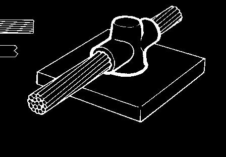


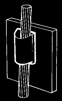
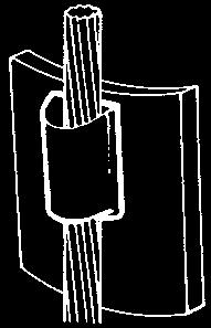
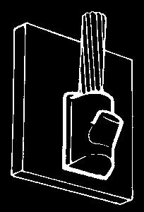
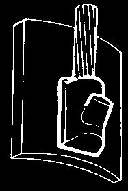
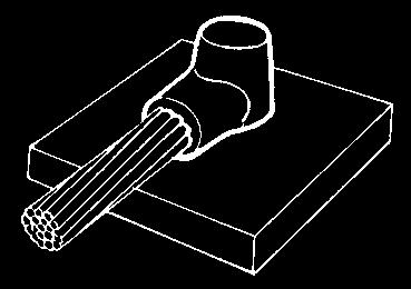

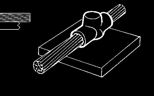


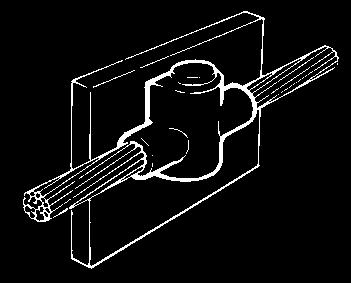


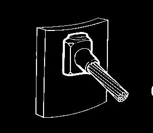
67 Exothermic Welding System Cable to Steel Surface and Pipe Quick Reference CS See page F-8 CS4 See page F-20 CS2 See page F-8 CS7 See page F-2 CS See page F-9 CS8 See page F-22 CS9 See page F-22 CS25 See page F-2 CS27 See page F-24 CS See page F-25 CS2 See page F-26 CS4 See page F-27 F-7
68 Exothermic Welding System CS Cable to Steel Surface and Pipe For Flat Surfaces Stranded conductor Solid circular conductor WIRE SIZE () WELDING POWDER SIZE HNDLE CLMP TYPE SLEEVE CS-4-/0 /0 90BKB HCPK4 CS-4-2/0 2/0 90BKB HCPK4 CS-4-/0 /0 5BKB HCPK4 CS-4-4/0 4/0 5BKB HCPK4 CS-4-250K 250 5BKB HCPK4 CS-4-00K 00 50BKB HCPK4 CS-4-50K BKB HCPK4 CS-4-500K BKB HCPK4 CS-4-750K x 50BKB HCPK4 CS-4-000K x 200BKB HCPK4 Mold Sealing Compound (MSC) will be required if surface is uneven. CS2 Cable to Steel Surface and Pipe For Flat Surfaces Stranded conductor Solid circular conductor STD. CTN. WIRE SIZE () WELDING POWDER SIZE HNDLE CLMP TYPE SLEEVE CS2-4-/0 /0 90BKB HCPK4 CS2-4-2/0 2/0 5BKB HCPK4 CS2-4-/0 /0 5BKB HCPK4 CS2-4-4/0 4/0 50BKB HCPK4 CS K BKB HCPK4 CS2-4-00K BKB HCPK4 CS2-4-50K BKB HCPK4 CS K x 50BKB HCPK4 Mold Sealing Compound (MSC) will be required if surface is uneven. STD. CTN. F-8
69 Exothermic Welding System CS Cable to Steel Surface and Pipe For Flat Surfaces Stranded conductor Solid circular conductor CS Cable to Steel Surface and Pipe For Pipes Stranded conductor Solid circular conductor WIRE SIZE () WELDING POWDER SIZE HNDLE CLMP TYPE SLEEVE STD. CTN. CS-4-#6 #6 45BKB HCPK4 SLEEVE#6 CS-4-#4 #4 45BKB HCPK4 CS-4-#2S #2 solid 45BKB HCPK4 CS-4-#2 #2 45BKB HCPK4 CS-4-# # 65BKB HCPK4 CS-4-/0 /0 90BKB HCPK4 CS-4-2/0 2/0 90BKB HCPK4 CS-4-/0 /0 5BKB HCPK4 CS-4-4/0 4/0 5BKB HCPK4 CS-4-250K 250 5BKB HCPK4 CS-4-00K 00 50BKB HCPK4 CS-4-50K BKB HCPK4 CS-4-500K BKB HCPK4 CS-5-750K X 50BKB HCPK5 CS-5-000K X 200BKB HCPK5 Mold Sealing Compound (MSC) will be required if surface is uneven. WIRE SIZE () PIPE SIZE (B) WELDING POWDER SIZE HNDLE CLMP TYPE SLEEVE STD. CTN. CS-4-#4C 2" 2 4" 45BKB HCPK4 CS-4-#4D 2 #4 4" 6 2" 45BKB HCPK4 CS-4-#4F 6 2" 0" 45BKB HCPK4 CS-4-#4G 0" 4" 45BKB HCPK4 CS-4-#2SC 2" 2 4" 45BKB HCPK4 CS-4-#2SD 2 #2 solid 4" 6 2" 45BKB HCPK4 CS-4-#2SF 6 2" 0" 45BKB HCPK4 CS-4-#2SG 0 4" 45BKB HCPK4 CS-4-#2C 2" 2 4" 45BKB HCPK4 CS-4-#2D 2 #2 4" 6 2" 45BKB HCPK4 CS-4-#2F 6 2" 0" 45BKB HCPK4 CS-4-#2G 0" 4" 45BKB HCPK4 CS-4-#C 2" 2 4" 65BKB HCPK4 CS-4-#D # 2 4" 6 2" 65BKB HCPK4 CS-4-#F 6 2" 0" 65BKB HCPK4 CS-4-#G 0" 4" 65BKB HCPK4 CS-4-#/0C 2" 2 4" 90BKB HCPK4 CS-4-#/0D 2 /0 4" 6 2" 90BKB HCPK4 CS-4-#/0F 6 2" 0" 90BKB HCPK4 CS-4-#/0G 0" 4" 90BKB HCPK4 CS-4-#2/0C 2" 2 4" 90BKB HCPK4 CS-4-#2/0D 2 2/0 4" 6 2" 90BKB HCPK4 CS-4-#2/0F 6 2" 0" 90BKB HCPK4 CS-4-#2/0G 0" 4" 90BKB HCPK4 CS-4-#/0C 2" 2 4" 5BKB HCPK4 CS-4-#/0D 2 /0 4" 6 2" 5BKB HCPK4 CS-4-#/0F 6 2" 0" 5BKB HCPK4 CS-4-#/0G 0" 4" 5BKB HCPK4 CS-4-#4/0C 2" 2 4" 5BKB HCPK4 CS-4-#4/0D 2 4/0 4" 6 2" 5BKB HCPK4 CS-4-#4/0F 6 2" 0" 5BKB HCPK4 CS-4-#4/0G 0" 4" 5BKB HCPK4 OVER 4": USE CS FOR FLT SURFCE. Use Mold Sealing Compound (MSC) to ensure effective sealing. F-9
70 Exothermic Welding System CS4 Cable to Steel Surface and Pipe For Flat Surfaces Stranded conductor Solid circular conductor WIRE SIZE () CS4 Cable to Steel Surface and Pipe For Pipes Stranded conductor Solid circular conductor WELDING POWDER SIZE HNDLE CLMP TYPE SLEEVE STD. CTN. CS4-4-#6 #6 90BKB HCPK4 SLEEVE#6 CS4-4-#4 #4 90BKB HCPK4 CS4-4-#2S #2 solid 5BKB HCPK4 CS4-4-#2 #2 5BKB HCPK4 CS4-4-# # 5BKB HCPK4 CS4-5-/0 /0 200BKB HCPK5 CS4-5-2/0 2/0 200BKB HCPK5 CS4-5-/0 /0 250BKB HCPK5 CS4-5-4/0 4/0 250BKB HCPK5 CS K BKB HCPK5 Mold Sealing Compound (MSC) will be required if surface is uneven. WIRE SIZE () PIPE SIZE (B) WELDING POWDER SIZE HNDLE CLMP TYPE SLEEVE STD. CTN. CS4-4-#4C 2" 2 4" 90BKB HCPK4 CS4-4-#4D 2 #4 4" 6 2" 90BKB HCPK4 CS4-4-#4F 6 2" 0" 90BKB HCPK4 CS4-4-#4G 0" 4" 90BKB HCPK4 CS4-4-#2SC 2" 2 4" 5BKB HCPK4 CS4-4-#2SD 2 #2 solid 4" 6 2" 5BKB HCPK4 CS4-4-#2SF 6 2" 0" 5BKB HCPK4 CS4-4-#2SG 0" 4" 5BKB HCPK4 CS4-4-#2C 2" 2 4" 5BKB HCPK4 CS4-4-#2D 2 #2 4" 6 2" 5BKB HCPK4 CS4-4-#2F 6 2" 0" 5BKB HCPK4 CS4-4-#2G 0" 4" 5BKB HCPK4 CS4-4-#C 2" 2 4" 5BKB HCPK4 CS4-4-#D # 2 4" 6 2" 5BKB HCPK4 CS4-4-#F 6 2" 0" 5BKB HCPK4 CS4-4-#G 0" 4" 5BKB HCPK4 CS4-5-/0C 2" 2 4" 200BKB HCPK5 CS4-5-/0D 2 /0 4" 6 2" 200BKB HCPK5 CS4-5-/0F 6 2" 0" 200BKB HCPK5 CS4-5-/0G 0" 4" 200BKB HCPK5 CS4-5-2/0C 2" 2 4" 200BKB HCPK5 CS4-5-2/0D 2 2/0 4" 6 2" 200BKB HCPK5 CS4-5-2/0F 6 2" 0" 200BKB HCPK5 CS4-5-2/0G 0" 4" 200BKB HCPK5 CS4-5-/0C 2" 2 4" 250BKB HCPK5 CS4-5-/0D 2 /0 4" 6 2" 250BKB HCPK5 CS4-5-/0F 6 2" 0" 250BKB HCPK5 CS4-5-/0G 0" 4" 250BKB HCPK5 CS4-5-4/0C 2" 2 4" 250BKB HCPK5 CS4-5-4/0D 2 4/0 4" 6 2" 250BKB HCPK5 CS4-5-4/0F 6 2" 0" 250BKB HCPK5 CS4-5-4/0G 0" 4" 250BKB HCPK5 OVER 4": USE CS4 FOR FLT SURFCE. Use Mold Sealing Compound (MSC) ensure effective sealing. F-20
71 Exothermic Welding System CS7 Cable to Steel Surface and Pipe For Flat Surfaces Stranded conductor Solid circular conductor WIRE SIZE () WELDING POWDER SIZE HNDLE CLMP TYPE SLEEVE CS7-4-#4 #4 65BKB HCPK4 CS7-4-#2S #2 solid 65BKB HCPK4 CS7-4-#2 #2 65BKB HCPK4 CS7-4-# # 90BKB HCPK4 CS7-4-/0 /0 90BKB HCPK4 CS7-4-2/0 2/0 50BKB HCPK4 CS7-5-/0 /0 200BKB HCPK4 CS7-5-4/0 4/0 200BKB HCPK4 CS K BKB HCPK4 CS7-5-00K BKB HCPK4 CS7-6-50K 50 2 X 50BKB HCPK5 CS K X 200BKB HCPK5 Use Mold Sealing Compound (MSC) to ensure effective sealing. CS7 Cable to Steel Surface and Pipe For Pipes Stranded conductor Solid circular conductor STD. CTN. WIRE SIZE () PIPE SIZE (B) WELDING POWDER SIZE HNDLE CLMP TYPE SLEEVE STD. CTN. CS7-4-#4C 2" to 2 4" 65BKB HCPK4 CS7-4-#4D 2 #4 4" to 6 2" 65BKB HCPK4 CS7-4-#4F 6 2" to 0" 65BKB HCPK4 CS7-4-#4G 0" to 4" 65BKB HCPK4 CS7-4-#2SC 2" to 2 4" 65BKB HCPK4 CS7-4-#2SD 2 #2 solid 4" to 6 2" 65BKB HCPK4 CS7-4-#2SF 6 2" to 0" 65BKB HCPK4 CS7-4-#2SG 0" to 4" 65BKB HCPK4 CS7-4-#2C 2" 2 4" 65BKB HCPK4 CS7-4-#2D 2 #2 4" 6 2" 65BKB HCPK4 CS7-4-#2F 6 2" 0" 65BKB HCPK4 CS7-4-#2G 0" 4" 65BKB HCPK4 CS7-4-#C 2" 2 4" 90BKB HCPK4 CS7-4-#D # 2 4" 6 2" 90BKB HCPK4 CS7-4-#F 6 2" 0" 90BKB HCPK4 CS7-4-#G 0" 4" 90BKB HCPK4 CS7-4-/0C 2" 2 4" 90BKB HCPK4 CS7-4-/0D 2 /0 4" 6 2" 90BKB HCPK4 CS7-4-/0F 6 2" 0" 90BKB HCPK4 CS7-4-/0G 0" 4" 90BKB HCPK4 CS7-4-2/0C 2" 2 4" 50BKB HCPK4 CS7-4-2/0D 2 2/0 4" 6 2" 50BKB HCPK4 CS7-4-2/0F 6 2" 0" 50BKB HCPK4 CS7-4-2/0G 0" 4" 50BKB HCPK4 CS7-5-/0C 2" 2 4" 200BKB HCPK4 CS7-5-/0D 2 /0 4" 6 2" 200BKB HCPK4 CS7-5-/0F 6 2" 0" 200BKB HCPK4 CS7-5-/0G 0" 4" 200BKB HCPK4 CS7-5-4/0C 2" 2 4" 200BKB HCPK4 CS7-5-4/0D 2 4/0 4" 6 2" 200BKB HCPK4 CS7-5-4/0F 6 2" 0" 200BKB HCPK4 CS7-5-4/0G 0" 4" 200BKB HCPK4 OVER 4": USE CS7 FOR FLT SURFCE. Use Mold Sealing Compound (MSC) to ensure effective sealing. F-2
72 Exothermic Welding System CS8 Cable to Steel Surface and Pipe For Flat Surfaces Stranded conductor Solid circular conductor WIRE SIZE () WELDING POWDER SIZE HNDLE CLMP TYPE SLEEVE CS8-2-#6 #6 45BKB HCPK2 SLEEVE#6 CS8-2-#4 #4 45BKB HCPK2 CS8-2-#2S #2 solid 45BKB HCPK2 CS8-2-#2 #2 45BKB HCPK2 CS8-2-# # 65BKB HCPK2 Use Mold Sealing Compound (MSC) to ensure effective sealing. CS9 Cable to Steel Surface and Pipe For Flat Surfaces STD. CTN. Stranded conductor Solid circular conductor WIRE SIZE () WELDING POWDER SIZE HNDLE CLMP TYPE SLEEVE CS9-2-#6 #6 45BKB HCPK2 SLEEVE#6 CS9-2-#4 #4 45BKB HCPK2 CS9-2-#2S #2 solid 45BKB HCPK2 CS9-2-#2 #2 45BKB HCPK2 CS9-2-# # 65BKB HCPK2 Use Mold Sealing Compound (MSC) to ensure effective sealing. STD. CTN. F-22
73 Exothermic Welding System CS25 Cable to Steel Surface and Pipe For Flat Surfaces Stranded conductor Solid circular conductor WIRE SIZE () WELDING POWDER SIZE CS25 Cable to Steel Surface and Pipe For Pipes Stranded conductor Solid circular conductor HNDLE CLMP TYPE SLEEVE CS25-4-#4 #4 65BKB HCPK4 CS25-4-#2S #2 solid 65BKB HCPK4 CS25-4-#2 #2 65BKB HCPK4 CS25-4-# # 90BKB HCPK4 CS25-4-/0 /0 5BKB HCPK4 CS25-4-2/0 2/0 5BKB HCPK4 CS25-4-/0 /0 50BKB HCPK4 CS25-4-4/0 4/0 50BKB HCPK4 CS K BKB HCPK4 CS K BKB HCPK4 CS K BKB HCPK4 CS K BKB HCPK4 Use Mold Sealing Compound (MSC) to ensure effective sealing. STD. CTN. WIRE SIZE () PIPE SIZE (B) WELDING POWDER SIZE HNDLE CLMP TYPE SLEEVE STD. CTN CS25-4-#4C 2" 2 4" 65BKB HCPK4 CS25-4-#4D 2 #4 4" 6 2" 65BKB HCPK4 CS25-4-#4F 6 2" 0" 65BKB HCPK4 CS25-4-#4G 0" 4" 65BKB HCPK4 CS25-4-#2SC 2" 2 4" 65BKB HCPK4 CS25-4-#2SD 2 #2 solid 4" 6 2" 65BKB HCPK4 CS25-4-#2SF 6 2" 0" 65BKB HCPK4 CS25-4-#2SG 0" 4" 65BKB HCPK4 CS25-4-#2C 2" 2 4" 65BKB HCPK4 CS25-4-#2D 2 #2 4" 6 2" 65BKB HCPK4 CS25-4-#2F 6 2" 0" 65BKB HCPK4 CS25-4-#2G 0" 4" 65BKB HCPK4 CS25-4-#C 2" 2 4" 90BKB HCPK4 CS25-4-#D 2 # 4" 6 2" 90BKB HCPK4 CS25-4-#F 6 2" 0" 90BKB HCPK4 CS25-4-#G 0" 4" 90BKB HCPK4 CS25-4-/0C 2" 2 4" 90BKB HCPK4 CS25-4-/0D 2 /0 4" 6 2" 90BKB HCPK4 CS25-4-/0F 6 2" 0" 90BKB HCPK4 CS25-4-/0G 0" 4" 90BKB HCPK4 CS25-4-2/0C 2" 2 4" 50BKB HCPK4 CS25-4-2/0D 2 2/0 4" 6 2" 50BKB HCPK4 CS25-4-2/0F 6 2" 0" 50BKB HCPK4 CS25-4-2/0G 0" 4" 50BKB HCPK4 CS25-4-/0C 2" 2 4" 200BKB HCPK4 CS25-4-/0D 2 /0 4" 6 2" 200BKB HCPK4 CS25-4-/0F 6 2" 0" 200BKB HCPK4 CS25-4-/0G 0" 4" 200BKB HCPK4 CS25-4-4/0C 2" 2 4" 200BKB HCPK4 CS25-4-4/0D 2 4/0 4" 6 2" 200BKB HCPK4 CS25-4-4/0F 6 2" 0" 200BKB HCPK4 CS25-4-4/0G 0" 4" 200BKB HCPK4 OVER 4": USE CS7 FOR FLT SURFCE. Use Mold Sealing Compound (MSC) to ensure effective sealing. F-2
74 Exothermic Welding System CS27 Cable to Steel Surface and Pipe For Flat Surfaces Stranded conductor Solid circular conductor WIRE SIZE () WELDING POWDER SIZE CS27 Cable to Steel Surface and Pipe For Pipes Stranded conductor Solid circular conductor HNDLE CLMP TYPE SLEEVE CS27-4-#6 #6 45BKB HCPK4 SLEEVE#6 CS27-4-#4 #4 45BKB HCPK4 CS27-4-#2S #2 solid 45BKB HCPK4 CS27-4-#2 #2 45BKB HCPK4 CS27-4-# # 65BKB HCPK4 CS27-4-/0 /0 5BKB HCPK4 CS27-4-2/0 2/0 5BKB HCPK4 CS27-4-/0 /0 50BKB HCPK4 CS27-4-4/0 4/0 50BKB HCPK4 CS K BKB HCPK4 Use Mold Sealing Compound (MSC) to ensure effective sealing. STD. CTN. WIRE SIZE () PIPE SIZE (B) WELDING POWDER SIZE HNDLE CLMP TYPE SLEEVE STD. CTN CS27-4-#4C 2" 2 4" 45BKB HCPK4 CS27-4-#4D 2 #4 4" 6 2" 45BKB HCPK4 CS27-4-#4F 6 2" 0" 45BKB HCPK4 CS27-4-#4G 0" 4" 45BKB HCPK4 CS27-4-#2SC 2" 2 4" 45BKB HCPK4 CS27-4-#2SD 2 #2 solid 4" 6 2" 45BKB HCPK4 CS27-4-#2SF 6 2" 0" 45BKB HCPK4 CS27-4-#2SG 0" 4" 45BKB HCPK4 CS27-4-#2C 2" 2 4" 45BKB HCPK4 CS27-4-#2D 2 #2 4" 6 2" 45BKB HCPK4 CS27-4-#2F 6 2" 0" 45BKB HCPK4 CS27-4-#2G 0" 4" 45BKB HCPK4 CS27-4-#C 2" 2 4" 65BKB HCPK4 CS27-4-#D # 2 4" 6 2" 65BKB HCPK4 CS27-4-#F 6 2" 0" 65BKB HCPK4 CS27-4-#G 0" 4" 65BKB HCPK4 CS27-4-0C 2" 2 4" 5BKB HCPK4 CS27-4-0D 2 /0 4" 6 2" 5BKB HCPK4 CS27-4-0F 6 2" 0" 5BKB HCPK4 CS27-4-0G 0" 4" 5BKB HCPK4 CS C 2" 2 4" 5BKB HCPK4 CS D 2 2/0 4" 6 2" 5BKB HCPK4 CS F 6 2" 0" 5BKB HCPK4 CS G 0" 4" 5BKB HCPK4 CS27-4-0C 2" 2 4" 50BKB HCPK4 CS27-4-0D 2 /0 4" 6 2" 50BKB HCPK4 CS27-4-0F 6 2" 0" 50BKB HCPK4 CS27-4-0G 0" 4" 50BKB HCPK4 CS C 2" 2 4" 50BKB HCPK4 CS D 2 4/0 4" 6 2" 50BKB HCPK4 CS F 6 2" 0" 50BKB HCPK4 CS G 0" 4" 50BKB HCPK4 OVER 4": USE CS7 FOR FLT SURFCE. Use Mold Sealing Compound (MSC) to ensure effective sealing. F-24
75 Exothermic Welding System CS Cable to Steel Surface and Pipe For Flat Surfaces Stranded conductor Solid circular conductor CS Cable to Steel Surface and Pipe For Pipes Stranded conductor Solid circular conductor WIRE SIZE () WELDING POWDER SIZE HNDLE CLMP TYPE SLEEVE CS-4-#6 #6 45BKB HCPK4 SLEEVE#6 CS-4-#4 #4 45BKB HCPK4 CS-4-#2S #2 solid 45BKB HCPK4 CS-4-#2 #2 45BKB HCPK4 CS-4-# # 65BKB HCPK4 CS-4-/0 /0 90BKB HCPK4 CS-4-2/0 2/0 90BKB HCPK4 CS-4-/0 /0 5BKB HCPK4 CS-4-4/0 4/0 5BKB HCPK4 CS-4-250K 250 5BKB HCPK4 CS-4-00K 00 50BKB HCPK4 CS-4-50K BKB HCPK4 CS-4-500K BKB HCPK4 dd R or L to denote wire exiting left or right. (Example: CS-6-#6R for #6 wire exiting on the right.) Use Mold Sealing Compound (MSC) to ensure effective sealing. HNDLE CLMP TYPE STD. CTN. WIRE SIZE () PIPE SIZE (B) WELDING POWDER SIZE SLEEVE STD. CTN. CS-4-#4C 2" 2 4" 45BKB HCPK4 CS-4-#4D 2 #4 4" 6 2" 45BKB HCPK4 CS-4-#4F 6 2" 0" 45BKB HCPK4 CS-4-#4G 0" 4" 45BKB HCPK4 CS-4-#2SC 2" 2 4" 45BKB HCPK4 CS-4-#2SD 2 #2 solid 4" 6 2" 45BKB HCPK4 CS-4-#2SF 6 2" 0" 45BKB HCPK4 CS-4-#2SG 0" 4" 45BKB HCPK4 CS-4-#2C 2" 2 4" 45BKB HCPK4 CS-4-#2D 2 #2 4" 6 2" 45BKB HCPK4 CS-4-#2F 6 2" 0" 45BKB HCPK4 CS-4-#2G 0" 4" 45BKB HCPK4 CS-4-#C 2" 2 4" 65BKB HCPK4 CS-4-#D # 2 4" 6 2" 65BKB HCPK4 CS-4-#F 6 2" 0" 65BKB HCPK4 CS-4-#G 0" 4" 65BKB HCPK4 CS-4-/0C 2" 2 4" 90BKB HCPK4 CS-4-/0D 2 /0 4" 6 2" 90BKB HCPK4 CS-4-/0F 6 2" 0" 90BKB HCPK4 CS-4-/0G 0" 4" 90BKB HCPK4 CS-4-2/0C 2" 2 4" 90BKB HCPK4 CS-4-2/0D 2 2/0 4" 6 2" 90BKB HCPK4 CS-4-2/0F 6 2" 0" 90BKB HCPK4 CS-4-2/0G 0" 4" 90BKB HCPK4 CS-4-/0C 2" 2 4" 5BKB HCPK4 CS-4-/0D 2 /0 4" to 6 2" 5BKB HCPK4 CS-4-/0F 6 2" 0" 5BKB HCPK4 CS-4-/0G 0" 4" 5BKB HCPK4 CS-4-4/0C 2" 2 4" 5BKB HCPK4 CS-4-4/0D 4/0 2 4" 6 2" 5BKB HCPK4 CS-4-4/0F 6 2" 0" 5BKB HCPK4 CS-4-4/0G 0" 4" 5BKB HCPK4 OVER 4": USE CS FOR FLT SURFCE. dd R or L to denote wire exiting left or right. (Example: CS-6-#6R for #6 wire exiting on the right.) Use Mold Sealing Compound (MSC) to ensure effective sealing. F-25
76 Exothermic Welding System CS2 Cable to Steel Surface and Pipe For Pipes Stranded conductor B B WIRE SIZE () PIPE SIZE (B) WELDING POWDER SIZE HNDLE CLMP TYPE SLEEVE STD. CTN. CS2-2-#4C 2" 2 4" 45BKB HCPK2 CS2-2#4D 2 #4 4" 6 2" 45BKB HCPK2 CS2-2-#4F 6 2" 0" 45BKB HCPK2 CS2-2-#4G 0" 4" 45BKB HCPK2 CS2-2-#2SC 2" 2 4" 45BKB HCPK2 CS2-2-#2SD 2 #2 solid 4" 6 2" 45BKB HCPK2 CS2-2-#2SF 6 2" 0" 45BKB HCPK2 CS2-2-#2SG 0" 4" 45BKB HCPK2 CS2-2-#2C 2" 2 4" 45BKB HCPK2 CS2-2-#2D 2 #2 4" 6 2" 45BKB HCPK2 CS2-2-#2F 6 2" 0" 45BKB HCPK2 CS2-2-#2G 0" 4" 45BKB HCPK2 CS2-2-#D 2 4" 6 2" 65BKB HCPK2 CS2-2-#F # 6 2" 0" 65BKB HCPK2 CS2-2-#G 0" 4" 65BKB HCPK2 OVER 4": USE CS8 FOR FLT SURFCE. CS2-4-#/0D 2 4" 6 2" 90BKB HCPK4 CS2-4-#/0F /0 6 2" 0" 90BKB HCPK4 CS2-4-#/0G 0" 4" 90BKB HCPK4 CS2-4-#2/0D 2 4" 6 2" 90BKB HCPK4 CS2-4-#2/0F 2/0 6 2" 0" 90BKB HCPK4 CS2-4-#2/0G 0" 4" 90BKB HCPK4 CS2-4-#/0D 2 4" 6 2" 90BKB HCPK4 CS2-4-#/0F /0 6 2" 0" 90BKB HCPK4 CS2-4-#/0G 0" 4" 90BKB HCPK4 CS2-4-#4/0D 2 4" 6 2" 90BKB HCPK4 CS2-4-#4/0F 4/0 6 2" 0" 90BKB HCPK4 CS2-4-#4/0G 0" 4" 90BKB HCPK4 OVER 4": USE CS FOR FLT SURFCE. dd R or L to denote wire exiting left or right. (Example: CS-6-#6R for #6 wire exiting on the right.) Use Mold Sealing Compound (MSC) to ensure effective sealing. F-26
77 Exothermic Welding System CS4 Cable to Steel Surface and Pipe For Pipes Stranded conductor B B WIRE SIZE () PIPE SIZE (B) WELDING POWDER SIZE HNDLE CLMP TYPE SLEEVE STD. CTN. CS4-2-#4C 2" to 2 4" 45BKB HCPK2 CS4-2-#4D 2 #4 4" to 6 2" 45BKB HCPK2 CS4-2-#4F 6 2" to 0" 45BKB HCPK2 CS4-2-#4G 0" to 4" 45BKB HCPK2 CS4-2-#2SC 2" to 2 4" 45BKB HCPK2 CS4-2-#2SD 2 #2S 4" to 6 2" 45BKB HCPK2 CS4-2-#2SF 6 2" to 0" 45BKB HCPK2 CS4-2-#2SG 0" to 4" 45BKB HCPK2 CS4-2-#2C 2" to 2 4" 45BKB HCPK2 CS4-2-#2D 2 #2 4" to 6 2" 45BKB HCPK2 CS4-2-#2F 6 2" to 0" 45BKB HCPK2 CS4-2-#2G 0" to 4" 45BKB HCPK2 CS4-2-#D 2 4" to 6 2" 65BKB HCPK2 CS4-2-#F # 6 2" to 0" 65BKB HCPK2 CS4-2-#G 0" to 4" 65BKB HCPK2 OVER 4": USE CS8 FOR FLT SURFCE CS4-4-#/0D 2 4" to 6 2" 90BKB HCPK4 CS4-4-#/0F /0 6 2" to 0" 90BKB HCPK4 CS4-4-#/0G 0" to 4" 90BKB HCPK4 CS4-4-#2/0D 2 4" to 6 2" 5BKB HCPK4 CS4-4-#2/0F 2/0 6 2" to 0" 5BKB HCPK4 CS4-4-#2/0G 0" to 4" 5BKB HCPK4 CS4-4-#/0D 2 4" to 6 2" 5BKB HCPK4 CS4-4-#/0F /0 6 2" to 0" 5BKB HCPK4 CS4-4-#/0G 0" to 4" 5BKB HCPK4 CS4-4-#4/0D 2 4" to 6 2" 50BKB HCPK4 CS4-4-#4/0F 4/0 6 2" to 0" 50BKB HCPK4 CS4-4-#4/0G 0" to 4" 50BKB HCPK4 OVER 4": USE CS FOR FLT SURFCE Use Mold Sealing Compound (MSC) to ensure effective sealing. F-27


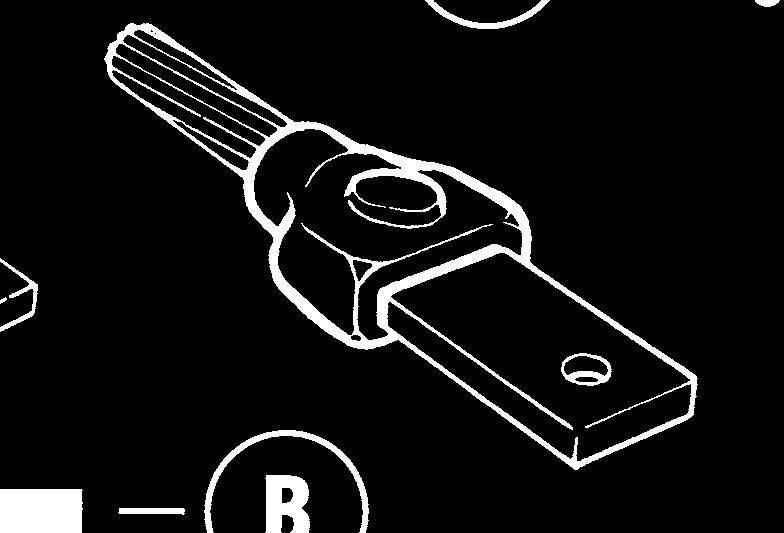
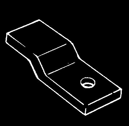
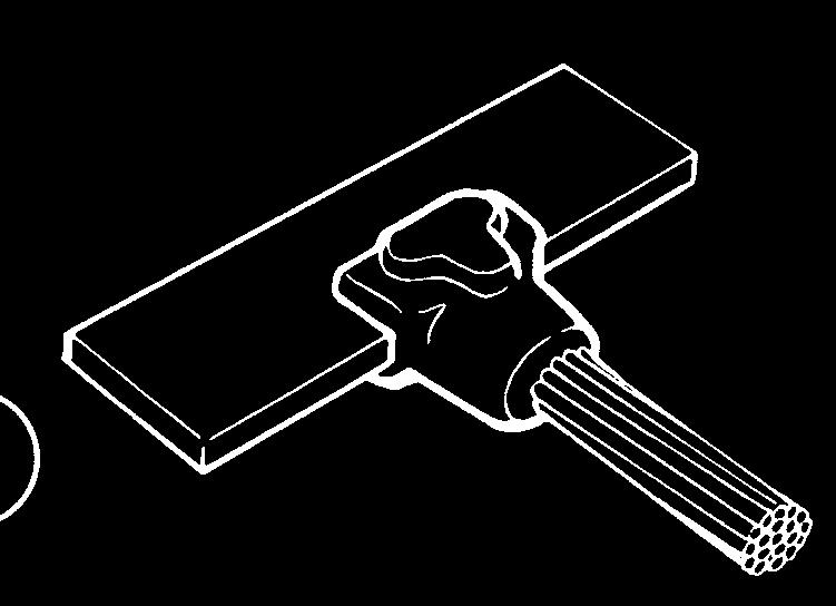
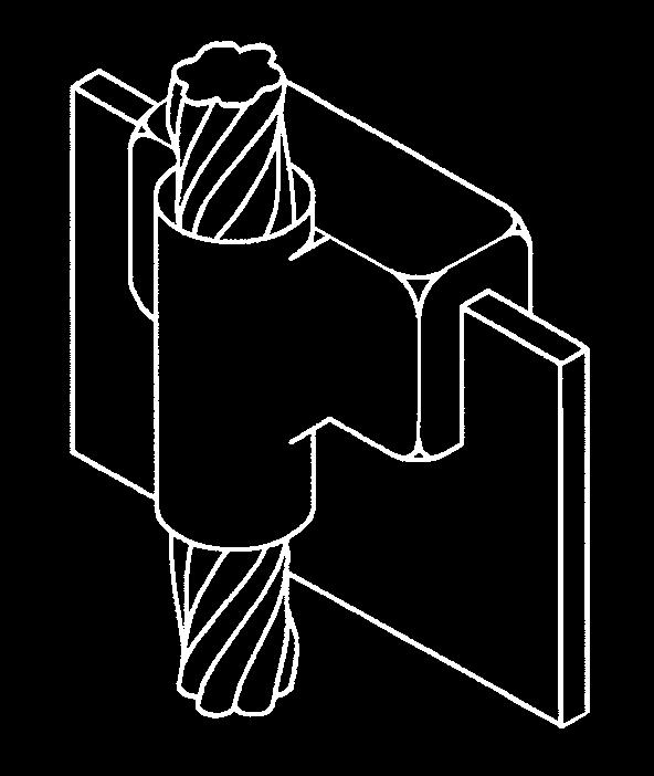
78 Exothermic Welding System Cable to Bar Quick Reference CB See page F-29 CB4 See page F-0 CB29 See page F- F-28
79 Exothermic Welding System CB Cable to Bar For Pipes Stranded conductor Solid circular conductor Rectangular tape or bar B WIRE SIZE () BR SIZE (B) WELDING POWDER SIZE HNDLE CLMP TYPE SLEEVE CB-4-#48 #4 8" x " 45BKB HCPK4 CB-4-#28 #2 solid 8" x " 45BKB HCPK4 CB-4-#28 #2 8" x " 45BKB HCPK4 CB-4-#8 # 8" x " 45BKB HCPK4 CB-4-/08 8" x " 45BKB HCPK4 CB-4-/06 /0 6" x " 65BKB HCPK4 CB-4-/04 4" x " 65BKB HCPK4 CB-4-2/08 8" x " 65BKB HCPK4 CB-4-2/06 2/0 6" x " 65BKB HCPK4 CB-4-2/04 4" x " 65BKB HCPK4 CB-4-/08 8" x " 65BKB HCPK4 CB-4-/06 /0 6" x " 90BKB HCPK4 CB-4-/04 4" X " 90BKB HCPK4 CB-4-4/06 6" x " 90BKB HCPK4 CB-4-4/04 4" x " 90BKB HCPK4 CB-4-4/042 4/0 4" x 2" 90BKB HCPK4 CB-4-4/042 4" x 2" 90BKB HCPK4 CB-4-4/04 4" x " 90BKB HCPK4 CB-4-250K6 6" x " 90BKB HCPK4 CB-4-250K4 4" x " 90BKB HCPK4 CB-4-250K " x 2" 90BKB HCPK4 CB-4-250K42 4" x 2" 90BKB HCPK4 CB-4-250K4 4" x " 90BKB HCPK4 CB-4-00K4 4" x " 90BKB HCPK4 CB-4-00K42 4" x 00 2" 90BKB HCPK4 CB-4-00K42 4" x 2" 90BKB HCPK4 CB-4-00K4 4" x " 90BKB HCPK4 CB-4-50K4 4" x " 5BKB HCPK4 CB-4-50K42 4" x 50 2" 5BKB HCPK4 CB-4-50K42 4" x 2" 5BKB HCPK4 CB-4-50K4 4" x " 5BKB HCPK4 CB-4-500K42 4" x 2" 200BKB HCPK4 CB-4-500K42 4" x 2" 200BKB HCPK4 500 CB-4-500K4 4" x " 200BKB HCPK4 CB-4-500K82 8" x 2" 200BKB HCPK4 CB-5-750K42 4" x 2" 2 x 50BKB HCPK5 CB-5-750K4 4" x ' 2 x 50BKB HCPK5 CB-5-750K " x 2" 2 x 50BKB HCPK5 CB-5-750K82 8" x 2" 2 x 50BKB HCPK5 CB-5-750K8 8" x " 2 x 50BKB HCPK5 CB-5-000K4 4" x " 2 x 200BKB HCPK5 CB-5-000K82 8" x 2" 2 x 200BKB HCPK5 CB-5-000K " x " 2 x 200BKB HCPK5 CB-5-000K22 2" x 2" 2 x 200BKB HCPK5 CB-5-000K2 2" x " 2 x 200BKB HCPK5 STD. CTN. F-29
80 Exothermic Welding System CB4 Cable to Bar For Flat Surfaces Stranded conductor Solid circular conductor Rectangular tape or bar B BR SIZE () WIRE SIZE (B) WELDING POWDER SIZE HNDLE CLMP TYPE STD. CTN. SLEEVE CB4-4-#2S42 #2 solid 45BKB HCPK4 CB #2 45BKB HCPK4 CB4-4-/042 /0 90BKB HCPK4 CB4-4-2/042 2/0 90BKB HCPK4 CB4-4-/042 /0 90BKB HCPK4 4" x 2" and wider CB4-4-4/042 4/0 90BKB HCPK4 CB K BKB HCPK4 CB4-4-00K BKB HCPK4 CB4-4-50K BKB HCPK4 CB K BKB HCPK4 CB4-4-#2S82 #2 solid 65BKB HCPK4 CB4-4-#282 #2 65BKB HCPK4 CB4-4-/082 /0 90BKB HCPK4 CB4-4-2/082 2/0 90BKB HCPK4 CB4-4-4/082 4/0 5BKB HCPK4 CB K82 8" x 2" and wider BKB HCPK4 CB4-4-00K BKB HCPK4 CB4-4-50K BKB HCPK4 CB K BKB HCPK4 CB K x 50BKB HCPK5 CB K x 200BKB HCPK5 CB4-4-#2S22 #2 solid 90BKB HCPK4 CB4-4-#222 #2 90BKB HCPK4 CB4-4-/022 /0 5BKB HCPK4 CB4-4-2/022 2/0 5BKB HCPK4 CB4-4-/022 /0 50BKB HCPK4 CB4-4-4/022 4/0 50BKB HCPK4 2" x 2" and wider CB K BKB HCPK4 CB4-4-00K BKB HCPK4 CB4-4-50K BKB HCPK4 CB K x 50BKB HCPK5 CB K x 200BKB HCPK5 CB K x 250BKB HCPK5 F-0
81 Exothermic Welding System CB29 Cable to Bar For Flat Surfaces B BR SIZE () WIRE SIZE (B) WELDING POWDER SIZE HNDLE CLMP TYPE SLEEVE CB29-9-#2S42 #2 solid 250BKB HCPK4 CB29-9-#242 #2 250BKB HCPK4 CB29-0-#42 # 2 x 50BKB HCPK5 CB29-0-/042 /0 2 x 200BKB HCPK5 CB29-0-2/042 4" x 2" and wider 2/0 2 x 200BKB HCPK5 CB29-0-4/042 4/0 2 x 250BKB HCPK5 CB K x 250BKB HCPK5 CB K x 250BKB HCPK5 CB K x 200BKB HCPK5 CB29-9-#2S82 #2 solid 250BKB HCPK4 CB29-9-#282 #2 solid 250BKB HCPK4 CB29-0-#82 # 2 x 50BKB HCPK5 CB29-0-/082 /0 2 x 200BKB HCPK5 CB29-02/082 8" x 2" and wider 2/0 2 x 200BKB HCPK5 CB29-04/082 4/0 2 x 250BKB HCPK5 CB K x 250BKB HCPK5 CB K x 250BKB HCPK5 CB K x 200BKB HCPK5 CB29-0-#2S22 #2 solid 2 x 50BKB HCPK5 CB29-0-#222 #2 2 x 50BKB HCPK5 CB29-0-#22 # 2 x 200BKB HCPK5 CB29-0-/022 /0 2 x 250BKB HCPK5 CB29-0-2/022 2" x 2" and wider 2/0 2 x 250BKB HCPK5 CB29-0-4/022 4/0 x 200BKB HCPK5 CB K x 200BKB HCPK5 CB K x 200BKB HCPK5 CB K 750 x 250BKB HCPK5 Use Mold Sealing Compound (MSC) to ensure effective sealing. STD. CTN. F-


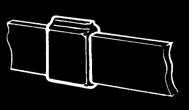
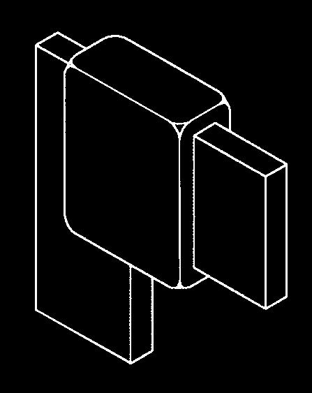
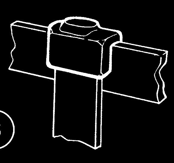


82 Exothermic Welding System Bar to Bar Quick Reference BB See page F- BB2 See page F- BB7 See page F-4 BB4 See page F-5 BB See page F-4 F-2
83 Exothermic Welding System BB Bar to Bar For Flat Surfaces BR SIZE () WELDING POWDER SIZE HNDLE CLMP TYPE SLEEVE BB-4-8 8" x " 45BKB HCPK4 BB " x 2" 65BKB HCPK4 BB " x 2" 90BKB HCPK4 BB-4-8 8" x " 200BKB HCPK4 BB " x 4" 250BKB HCPK4 BB-4-6 6" x " 65BKB HCPK4 BB " x 2" 5BKB HCPK4 BB-4-4 4" x " 90BKB HCPK4 BB " x 4" 5BKB HCPK4 BB " x 2" 50BKB HCPK4 BB " x 2" 200BKB HCPK4 BB " x 2 2" 250BKB HCPK4 BB-5-4 4" x " 2 x 200BKB HCPK5 BB " x 4" 2 x 250BKB HCPK5 BB-4-8 8" x " 50BKB HCPK5 BB " x 2" 250BKB HCPK4 BB " x 2" 2 x 50BKB HCPK5 BB-5-8 8" x " 2 x 250BKB HCPK5 BB " x 4" x 200BKB HCPK5 BB-4-2 2" x " 200BKB HCPK4 BB " x 2" 2 x 200BKB HCPK5 STD. CTN. BB2 Bar to Bar For Flat Surfaces BR SIZE () WELDING POWDER SIZE HNDLE CLMP TYPE SLEEVE BB " x " 45BKB HCPK4 BB " x 2" 65BKB HCPK4 BB " x 2" 90BKB HCPK4 BB " x " 200BKB HCPK4 BB " x 4" 250BKB HCPK4 BB " x " 65BKB HCPK4 BB " x 2" 5BKB HCPK4 BB " x " 90BKB HCPK4 BB " x 4" 5BKB HCPK4 BB " x 2" 50BKB HCPK4 BB " x 2" 200BKB HCPK4 BB " x 2 2" 250BKB HCPK4 BB " x " 2 x 200BKB HCPK5 BB " x 4" 2 x 250BKB HCPK5 BB " x " 50BKB HCPK5 BB " x 2" 250BKB HCPK4 BB " x 2" 2 x 50BKB HCPK5 BB " x " 2 x 250BKB HCPK5 BB " x 4" x 200BKB HCPK5 BB " x " 200BKB HCPK4 BB " x 2" 2 x 200BKB HCPK5 STD. CTN. F-
84 Exothermic Welding System BB Bar to Bar For Flat Surfaces BR SIZE () WELDING POWDER SIZE HNDLE CLMP TYPE SLEEVE BB-4-8 8" x " 45BKB HCPK4 BB " x 2" 65BKB HCPK4 BB " x 2" 90BKB HCPK4 BB-4-8 8" x " 200BKB HCPK4 BB " x 4" 250BKB HCPK4 BB-4-6 6" x " 65BKB HCPK4 BB " x 2" 5BKB HCPK4 BB-4-4 4" x " 90BKB HCPK4 BB " x 4" 5BKB HCPK4 BB " x 2" 50BKB HCPK4 BB " x 2" 200BKB HCPK4 BB " x 2 2" 250BKB HCPK4 BB-5-4 4" x " 2 x 200BKB HCPK5 BB " x 4" 2 x 250BKB HCPK5 BB-4-8 8" x " 50BKB HCPK5 BB " x 2" 250BKB HCPK4 BB " x 2" 2 x 50BKB HCPK5 BB-5-8 8" x " 2 x 250BKB HCPK5 BB " x 4" x 200BKB HCPK5 BB-4-2 2" x " 200BKB HCPK4 BB " x 2" 2 x 200BKB HCPK5 STD. CTN. BB7 Bar to Bar For Flat Surfaces BR SIZE () WELDING POWDER SIZE HNDLE CLMP TYPE SLEEVE BB " x " 45BKB HCPK4 BB " x 2" 65BKB HCPK4 BB " x 2" 90BKB HCPK4 BB " x " 200BKB HCPK4 BB " x 4" 250BKB HCPK4 BB " x " 65BKB HCPK4 BB " x 2" 5BKB HCPK4 BB " x " 90BKB HCPK4 BB " x 4" 5BKB HCPK4 BB " x 2" 50BKB HCPK4 BB " x 2" 200BKB HCPK4 BB " x 2 2" 250BKB HCPK4 BB " x " 2 x 200BKB HCPK5 BB " x 4" 2 x 250BKB HCPK5 BB " x " 50BKB HCPK5 BB " x 2" 250BKB HCPK4 BB " x 2" 2 x 50BKB HCPK5 BB " x " 2 x 250BKB HCPK5 BB " x 4" x 200BKB HCPK5 BB " x " 200BKB HCPK4 BB " x 2" 2 x 200BKB HCPK5 STD. CTN. F-4
85 Exothermic Welding System BB4 Bar to Bar For Flat Surfaces BR SIZE () WELDING POWDER SIZE HNDLE CLMP TYPE BB " x " 45BKB HCPK4 BB " x 2" 65BKB HCPK4 BB " x 2" 90BKB HCPK4 BB " x " 200BKB HCPK4 BB " x 4" 250BKB HCPK4 BB " x " 65BKB HCPK4 BB " x 2" 5BKB HCPK4 BB " x " 90BKB HCPK4 BB " x 4" 5BKB HCPK4 BB " x 2" 50BKB HCPK4 BB " x 2" 200BKB HCPK4 BB " x 2 2" 250BKB HCPK4 BB " x " 2 x 200BKB HCPK5 BB " x 4" 2 x 250BKB HCPK5 BB " x " 50BKB HCPK5 BB " x 2" 250BKB HCPK4 BB " x 2" 2 x 50BKB HCPK5 BB " x " 2 x 250BKB HCPK5 BB " x 4" x 200BKB HCPK5 BB " x " 200BKB HCPK4 BB " x 2" 2 x 200BKB HCPK5 SLEEVE STD. CTN. F-5


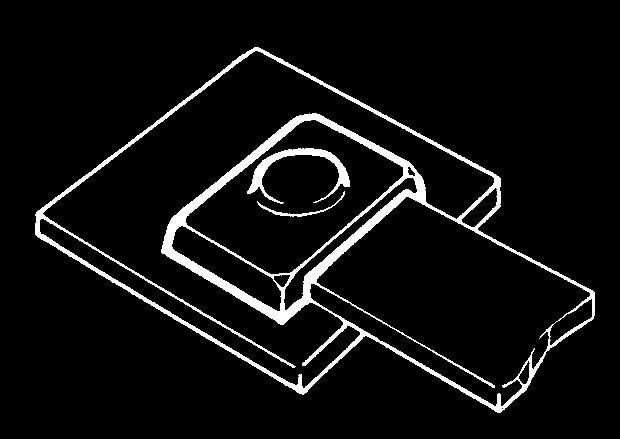


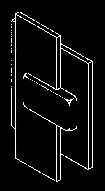
86 Exothermic Welding System Bar to Steel Surface Quick Reference BS BS4 See page F-7 See page F-8 BS2 BS5 See page F-7 See page F-9 BS See page F-8 F-6
87 Exothermic Welding System BS Bar to Steel Surface For Flat Surfaces Rectangular tape or bar BS2 Bar to Steel Surface For Flat Surfaces BR SIZE () WELDING POWDER SIZE HNDLE CLMP TYPE SLEEVE STD. CTN. BS-4-8 8" x " 5BKB HCPK4 4 BS " x 2" 50BKB HCPK4 4 BS " x 2" 200BKB HCPK4 4 BS-4-6 6" x " 50BKB HCPK4 4 BS " x 2" 200BKB HCPK4 4 BS " x 2" 250BKB HCPK4 4 BS-4-4 4" x " 50BKB HCPK4 4 BS " x 4" 200BKB HCPK4 4 BS " x 2" 250BKB HCPK4 4 BS " x 2" 2 x 50BKB HCPK4 4 BS-4-8 8" x " 200BKB HCPK5 4 BS " x 2" 250BKB HCPK4 4 BS " x 2" 2 x 200BKB HCPK5 5 BS-4-2 2" x " 250BKB HCPK4 4 BS " x 2" 2 x 200BKB HCPK5 5 BS " x 2" 2 x 250BKB HCPK5 5 Mold Sealing Compound (MSC) will be required if surface is uneven. Rectangular tape or bar BR SIZE () WELDING POWDER SIZE HNDLE CLMP TYPE SLEEVE STD. CTN. BS " X " 5BKB HCPK4 BS " X 2" 50BKB HCPK4 BS " X 2" 200BKB HCPK4 BS " X " 50BKB HCPK4 BS " X 2" 200BKB HCPK4 BS " X 2" 250BKB HCPK4 BS " X " 50BKB HCPK4 BS " X 4" 200BKB HCPK4 BS " X 2" 250BKB HCPK4 BS " X 2" 2 X 50BKB HCPK4 BS " X " 200BKB HCPK5 BS " X 2" 250BKB HCPK4 BS " X 2" 2 X 200BKB HCPK5 BS " X " 250BKB HCPK4 BS " X 2" 2 X 200BKB HCPK5 BS " X 2" 2 X 250BKB HCPK5 Mold Sealing Compound (MSC) will be required if surface is uneven. F-7
88 Exothermic Welding System BS Bar to Steel Surface For Flat Surfaces Rectangular tape or bar BS4 Bar to Steel Surface For Flat Surfaces BR SIZE () WELDING POWDER SIZE HNDLE CLMP TYPE SLEEVE STD. CTN. BS-4-8 8" x " 5BKB HCPK4 BS " x 2" and wider 50BKB HCPK4 BS-4-6 6" x " 50BKB HCPK4 BS " x 2" and wider 200BKB HCPK4 BS-4-4 4" x " 50BKB HCPK4 BS " x 4" 200BKB HCPK4 BS " x 2" and wider 250BKB HCPK4 BS-4-8 8" x " 200BKB HCPK5 BS " x 2" and wider 250BKB HCPK4 BS-4-2 2" x " 250BKB HCPK4 BS " x 2" and wider 2 x 200BKB HCPK5 Mold Sealing Compound (MSC) will be required if surface is uneven. Rectangular tape or bar BR SIZE () WELDING POWDER SIZE HNDLE CLMP TYPE SLEEVE STD. CTN. BS " x " 5BKB HCPK4 BS " x 2" 50BKB HCPK4 BS " x 2" 200BKB HCPK4 BS " x " 50BKB HCPK4 BS " x 2" 200BKB HCPK4 BS " x 2" 250BKB HCPK4 BS " x " 50BKB HCPK4 BS " x 4" 200BKB HCPK4 BS " x 2" 250BKB HCPK4 BS " x 2" 2 x 50BKB HCPK4 BS " x " 200BKB HCPK5 BS " x 2" 250BKB HCPK4 BS " x 2" 2 x 200BKB HCPK5 BS " x " 250BKB HCPK4 BS " x 2" 2 x 200BKB HCPK5 BS " x 2" 2 x 250BKB HCPK5 Mold Sealing Compound (MSC) will be required if surface is uneven. F-8
89 Exothermic Welding System BS5 Bar to Steel Surface For Flat Surfaces BR SIZE () WELDING POWDER SIZE HNDLE CLMP TYPE SLEEVE BS " x " 5BKB HCPK4 BS " x 2" 50BKB HCPK4 BS " x 2" and wider 200BKB HCPK4 BS " x " 50BKB HCPK4 BS " x 2" 200BKB HCPK4 BS " x 2" and wider 250BKB HCPK4 BS " x " 50BKB HCPK4 BS " x 4" 200BKB HCPK4 BS " x 2" 250BKB HCPK4 BS " x 2" and wider 2 x 50BKB HCPK5 BS " x " 200BKB HCPK5 BS " x 2" 250BKB HCPK4 BS " x 2" and wider 2 x 200BKB HCPK5 BS " x " 250BKB HCPK4 BS " x 2" 2 x 200BKB HCPK5 BS " x 2" and wider 2 x 250BKB HCPK5 Mold Sealing Compound (MSC) will be required if surface is uneven. STD. CTN. F-9
90 Exothermic Welding System Tools and ccessories STM-TB FGUN DESCRIPTION PPLICTIONS STD. CTN. WWB Cable Cleaning Brush Cleaning of stranded and other circular 6 section conductors WRB Replacement Elements (Pair) BFC Card Cloth Brush Cleaning of conductors and surfaces 0 FGUN Flint Ignitor Gun Starting powder ignition 0 BCM Mold Cleaning Brush Soft brush for mold cleaning 0 STM-TB Mold Scraper Tool Break up and removal of slag in mold crucible 0 MSC Mold Sealing Compound Mold sealing on uneven surfaces, 5 and general mold sealing PCK- Packing Mold sealing on rebar surfaces 50 SLEEVE#6 Sleeve for #6 wire Prevents burning of small section wire 00 SLEEVE#6S Sleeve for #6S wire Prevents burning of small section wire 00 SLEEVE#8 Sleeve for #8 wire Prevents burning of small section wire 00 SLEEVE#8S Sleeve for #8S wire Prevents burning of small section wire 00 SHIM Copper shim For sealing around undersize conductors 00 BCM BFC F-40
91 Exothermic Welding System Handle Clamps HCPK HCPK4 HCPK2 DESCRIPTION PPLICTIONS STD. CTN. HCPK Price Key Handle For use on price key molds HCPK2 Price Key 2 Handle For use on price key 2 molds HCPK Price Key Handle Clamp For use on price key molds HCPK Price Key Handle Clamp Type molds (connections to vertical rebars) HCPKB Price Key B Handle Clamp Type B molds (connections to horizontal rebars) HCPKBMOD Price Key Type B molds (cross connections B Modified Clamp to horizontal rebars) HCPK4 Price Key 4 Handle Clamp For use on price key 4 molds HCPK5 Price Key 5 Handle Clamp For use on price key 5 molds HCPK7 Price Key 7 Handle Clamp For use on price key 7 molds HCPK8 Price Key 8 Handle Clamp For use on price key 8 molds FRME Price Key 9 Frame For use with HCPK4 on price key 9 molds FRME2 Price Key 0 Frame For use with HCPK5 on price key 0 molds FRME F-4


92 Exothermic Welding System Quick, easy and disposable no maintenance required! Sure Shot Welding Mold for Conductor to Copper Ground Rod Fast and simple to use Maintenance-free disposable molds Packaged with everything necessary to make a connection Biodegradable ceramic mold can be left underground Ergonomic hexagonal design allows easy handling, even with gloves For the ultimate in speedy, convenient connections, try the Sure Shot Welding Mold, an extension of the Blackburn line of exothermic welding products. Sure Shot molds come packaged with all of the components you need to make a connection. The mold s hexagonal shape makes it easy to pick up and hold without removing your safety gloves and also ensures that it won t roll away while you re preparing the connection. To make a connection, simply position the Sure Shot mold, add the weld powder and starting powder and ignite with a flint gun. It s that easy. Since Sure Shot molds are disposable, there s no need to clean them after use. In fact, you don t even have to remove the molds from underground installations, because they re made of earthfriendly biodegradable ceramic. Dimensions.794".549".74".450" Cover Welding Mold Disk F-42
E-Z-Ground Grounding Systems. Ground Wire Size. Water Pipe Size. 1/2 in /4 in. 2 in /2 in. 3-1/2 in TB
 Waterpipe Ground Clamps Cat. No. Ground Wire Size Water Pipe Size 2-TB 1/2 in., 3/4 in., 1 or rebar 4-10 3-TB 1-1/4 in., 1-1/2 in. or 2 in. #6, #4, 4 2-1/2 in., 3 in. or 3-1/2 in. #2 WG 5-TB 4 in., 4-1/2
Grounding Systems. Table of Contents. EZGround
 EZGround Grounding Systems Table of Contents Thomas & etts offers a complete range of grounding products including mechanical, compression and exothermic systems. Whatever the application, there is a Thomas
Electrical Metallic Tubing (EMT) Fittings
 Fittings") Suggested Specifications for Electrical Metallic Tubing (EMT) Fittings Series 2 Insulated EMT Connector (Raintight) (Compression Type) Series 20 EMT Coupling (Raintight) (Compression Type) Series 0 Pipe
Suggested Specifications for Electrical Metallic Tubing (EMT) Fittings Series 2 Insulated EMT Connector (Raintight) (Compression Type) Series 20 EMT Coupling (Raintight) (Compression Type) Series 0 Pipe
Specifications Electrical Metallic Tubing (EMT)
") T& Fittings Specifications Electrical Metallic Tubing (EMT) Ref. CEC Rule 12-000 not exceeding 750 Volts Electrical Metallic Tubing (EMT) is similar to rigid steel conduit but is much lighter, weighing
T& Fittings Specifications Electrical Metallic Tubing (EMT) Ref. CEC Rule 12-000 not exceeding 750 Volts Electrical Metallic Tubing (EMT) is similar to rigid steel conduit but is much lighter, weighing
Mechanical Connectors Product Overview
 Product Overview......................... 40 Split-Bolt Connectors.................. 4-44 Service Post Connectors................ 4-46 Mechanical Service Entrance Connectors...... 4 Parallel Groove Connectors.............
Service Entrance Cable Fittings
 Suggested Specifications for Service Entrance Fittings All service fittings shall be approved for the purpose by a nationally recognized testing laboratory, inspection agency or product evaluation organization.
Fig. 1 - Standard Clevis Hanger
 Revision 10/24/2007 Fig. 1 - Standard Clevis Hanger Component of State of California OSHPD Approved Seismic Restraints System Size Range Size 1/2" thru 36" pipe. Function Recommended for the suspension
TEMPORARY PROTECTIVE GROUNDING EQUIPMENT
 TEMPORARY PROTECTIVE GROUNDING EQUIPMENT TEMPORARY PROTECTIVE GROUNDING EQUIPMENT NOTE: When ordeing assemblies of grounding products, please make sure all items included in the assembly are only from
SECTION GROUNDING AND BONDING
 SECTION 16060 PART 1 GENERAL 1.01 DESCRIPTION A. Section includes requirements for an electrical grounding system, including electrodes, grounding rods, connectors, insulators, equipment grounding and
Materials Carbon Steel is used in the manufacturing of riser and pipe clamps. Stainless Steel and other materials are available.
 Pipe clamps offered in this section are designed for support and attachment of pipe to structural members. wide range of pipe clamps are available for various applications. Materials arbon Steel is used
Mechanical. Mechanical
 Connectors Quick Reference...C-6 Split-Bolt Connectors...C- C- Service Post Connectors...C-20 C-2 Parallel Groove Connectors...C-22 Insulated Conductor Connectors...C-2 Two-Bolt Connectors...C-24 C-2 MT
thermoweld The Contractors Choice GREAT PRODUCTS GREAT SERVICE GREAT PEOPLE
 The Contractors Choice the Contractors Choice Founded in 1958, with locations in Tulsa and Broken Arrow, Oklahoma. is part of the Quality Brands of Continental Industries. TABLE OF CONTENTS THE PROCESS...4
NORTHWESTERN UNIVERSITY PROJECT NAME JOB # ISSUED: 03/29/2017
 SECTION 26 0526 - GROUNDING AND BONDING FOR ELECTRICAL SYSTEMS PART 1 - GENERAL 1.1 RELATED DOCUMENTS A. Drawings and general provisions of the Contract, including General and Supplementary Conditions
1. Hangers and supports for electrical equipment and systems. 2. Construction requirements for concrete bases.
 SECTION 260529 - HANGERS AND SUPPORTS PART 1 - GENERAL 1.1 SUMMARY A. Section includes: 1. Hangers and supports for electrical equipment and systems. 2. Construction requirements for concrete bases. 1.2
Mechanical Connectors Product Overview
 Product Overview......................... 40 Split-Bolt Connectors.................. 4-44 Service Post Connectors................ 4-46 Mechanical Service Entrance Connectors...... 4 Parallel Groove Connectors.............
Fig Beam Clamp Retaining Strap (B-Line B3367)
") Fig. 69 - Beam Clamp Retaining Strap (B-Line B3367) Size Range: 3 /8"-16 thru 3 /4"-10 rod 4 (101.6mm) thru 16 (406.4mm) lengths Note: longer lengths are available consult factory Material: Pre-Galvanized
Fig. 69 - Beam Clamp Retaining Strap (B-Line B3367) Size Range: 3 /8"-16 thru 3 /4"-10 rod 4 (101.6mm) thru 16 (406.4mm) lengths Note: longer lengths are available consult factory Material: Pre-Galvanized
Materials Carbon Steel is used in the manufacturing of riser and pipe clamps. Stainless Steel and other materials are available.
 Pipe clamps offered in this section are designed for support and attachment of pipe to structural members. wide range of pipe clamps are available for various applications. Materials arbon Steel is used
SECTION CHAIN-LINK FENCES AND GATES 02821/1
 SECTION 02821 - CHAIN-LINK FENCES AND GATES 02821/1 PART 1 - GENERAL 1.1 SUMMARY A. This Section includes the following: 1. Chain-Link Fences: 2. Gates: horizontal slide or swing. 3. Fences installed where
UNDERGROUND SERVICES SECONDARY
 Reference UNDERGROUND SERVICES SECONDARY Underground services secondary... U- 1 General requirements for underground service... U- 2 Name of parts for underground service... U- 3 Conduit layouts... U-
SECTION HANGERS AND SUPPORTS FOR ELECTRICAL SYSTEMS
 SECTION 26 05 29 HANGERS AND SUPPORTS FOR ELECTRICAL SYSTEMS PART 1 GENERAL 1.1 DESCRIPTION A. Scope: 1. CONTRACTOR shall provide all labor, materials, equipment, and incidentals as shown, specified, and
SEISMIC PROTECTION SYSTEMS Bracing Products for Racks & Cabinets
 SEISMIC PROTECTION SYSTEMS Bracing Products for Racks & Cabinets Seismic Frame Two-Post Rack Page 11-3 Seismic Protection Products - Racks Page 11-6 Seismic Protection Products - Runway Page 11-8 Seismic
A. Product Data shall be provided for each type of product indicated.
 32 31 13 CHAIN LINK FENCES AND GATES SECTION 1 GENERAL 1.1 SUMMARY This Section includes the following: 1. Chain Link Fences 2. Gates for Chain Link Fences. See electrical specifications for electrical
Superstrut. Metal Framing. Pipe Straps, Pipe Clamps and Hangers
 Design Loads Where design loads are indicated, they provide for a safety factor of 3 in conformance with the American Standard Code for Pressure Piping. Hanger Design Pipe hangers are of advanced design
TOLCO Fire Protection Support Systems. Pipe Hangers Supports Seismic Bracing. UL Listed FM Approved for Fire Sprinkler Installations
 TOLCO Fire Protection Support Systems Pipe Hangers Supports Seismic Bracing UL Listed FM Approved for Fire Sprinkler Installations Revision 12/06/2007 Catalog Forward This catalog has been created with
Materials Carbon Steel and Malleable Iron are used in the manufacture of concrete inserts. Stainless Steel and other materials are available.
 Concrete inserts offered in this section are designed to provide a pre-set support point in concrete ceilings, walls, and floors. A range of inserts with varying design loads are available. Materials Carbon
Small Terminals. TEST CURRENT (Amps) Fig 1. Tensile strength of YAD HYLUG after axial rotation stresses. TENSILE STRENGTH IN POUNDS
 Fig 1. Tensile strength of YAD HYLUG after axial rotation stresses. TENSILE STRENGTH IN POUNDS") B-2 Performance The terminals and splices in this catalog are approved, per MIL-T-7928 and/or UL 486, where indicated. Table 1 shows the performance requirements for terminals used in military and commercial
B-2 Performance The terminals and splices in this catalog are approved, per MIL-T-7928 and/or UL 486, where indicated. Table 1 shows the performance requirements for terminals used in military and commercial
PATHWAYS FOR COMMUNICATIONS SYSTEMS
 270528 PATHWAYS FOR PART 1 GENERAL 1.1 WORK INCLUDED A. Provide all labor, materials, and equipment for the complete installation of work called for in the Contract Documents. 1.2 SCOPE OF WORK A. This
 Meter Swivels Insulated Unions Meter Sets Meter Accessories The Right Connection 1-800-654-3872 1-405-273-6302 www.centralplastics.com : Overview Georg Fischer Central Plastics entered the meter connection
A. All materials shall be tested and listed by an OSHA approved Nationally Recognized Testing Laboratory (NRTL).
.") 16450 GROUNDING ************************************************************************************************************* SPECIFIER: CSI MasterFormat 2004 number: 26 05 26 An optional keynote to the
16450 GROUNDING ************************************************************************************************************* SPECIFIER: CSI MasterFormat 2004 number: 26 05 26 An optional keynote to the
This product specification is written according to the Construction Specifications Institute MasterFormat, 2014 Update.
 Kaf-Tech Product Specification This product specification is written according to the Construction Specifications Institute MasterFormat, 2014 Update. SECTION 260519 METAL CLAD CABLE - MC-PLUS Neutral
MERCHANTS METALS. A. ASTM F552 Standard Terminology Relating to Chain Link Fencing
 MERCHANTS METALS SECTION 32 31 13 COLORBOND CHAIN LINK FENCE AND GATES 2014 PART 1 GENERAL 1.1 RELATED DOCUMENTS A. DIVISION 01 - GENERAL REQUIREMENTS: Drawings, quality, product and performance requirements,
Com-Tray. Under Floor
 Com-Tray Chalfant, a leading supplier of cable trays and systems for utilities, industrial plants, and commercial service, offers Com-Tray, a unique modular, cost-saving system for routing and protecting
SECTION VIBRATION AND SEISMIC CONTROLS FOR ELECTRICAL SYSTEMS
 PART 1 - GENERAL 1.1 RELATED DOCUMENTS A. Drawings and general provisions of the Contract, including General and Supplementary Conditions, apply to this Section. 1.2 SUMMARY A. This Section includes the
SECTION (Master Template Final-05) ELECTRICAL BOXES. A. Provide boxes for electrical equipment and wiring devices as follows:
 ELECTRICAL BOXES. A. Provide boxes for electrical equipment and wiring devices as follows:") SECTION 16130 (Master Template Final-05) ELECTRICAL BOXES PART 1 GENERAL 1.01 SECTION INCLUDES A. Provide boxes for electrical equipment and wiring devices as follows: 1. Wall and ceiling outlet boxes.
SECTION 16130 (Master Template Final-05) ELECTRICAL BOXES PART 1 GENERAL 1.01 SECTION INCLUDES A. Provide boxes for electrical equipment and wiring devices as follows: 1. Wall and ceiling outlet boxes.
 Copper and Copper Alloy Tube, Pipe and Fittings COPPER and COPPER ALLOY TUBE and PIPE Seamless Copper Pipe: Copper pipe is almost pure copper manufactured to the requirements of ASTM B 42 - Standard Specification
SECTION HANGERS AND SUPPORTS FOR PLUMBING PIPING AND EQUIPMENT
 SECTION 220529 - PART 1 - GENERAL 1.1 SUMMARY A. This Section includes the following: 1. Steel pipe hangers and supports. 2. Metal framing systems. 3. Thermal-hanger shield inserts. 4. Fastener systems.
Welding Accessories
 Welding Accessories www.airliquide.ca 1-800-817-7697 Welding Accessories BLUESHIELD Welding Cables Blueshield Welding Cables: Excellent flexibility (stays flexible at -50 C) Abrasion resistant Oil, solvent
SECTION CRL50 AND CRL51 HEAVY GLASS TOP HUNG SLIDING DOOR SYSTEMS
 SECTION 08 32 20 CRL50 AND CRL51 HEAVY GLASS TOP HUNG SLIDING DOOR SYSTEMS Page 1 of 6 USE THIS SECTION WHEN SPECIFYING OVERHEAD SUPPORTED GLASS PANEL PARTITIONS. SECTION INCLUDES OVERHEAD TRACK ASSEMBLY,
B-LINE SERIES. DURA-BLOK rooftop supports BRTS-17 DURA-BLOK. A complete rooftop support solution
 DURA-BLOK rooftop supports BRTS-17 B-LINE SERIES DURA-BLOK A complete rooftop support solution DURA-BLOK rooftop solutions support DURA-BLOK supports are made of 100% recycled rubber and are designed to
Title: YALE OFFICE OF FACILITIES PROCEDURE MANUAL Chapter: 01 - Yale Design Standard Division: Electrical Standards
 Date Description of Change Pages / Sections Modified ID 6/15/16 Updated format, division title, and removed references to other sections. - mgl44 A. Summary This section contains design criteria for the
CONDUITS AND FITTINGS
 CONDUIT AND FITTINGS Rigid Steel Conduit 3801 Rigid PVC Conduit 3803 HDPE Conduit 3803 Flexible Non Metallic Liquid Tight Conduit Type LFNC-B 3804 PVC Coated Urethane Lined Galvanized Rigid Steel Conduit
PV Mounting System 2703 SERIES 200 UL GROUND MOUNT SYSTEM. SnapNrack Residential PV Mounting Systems Code Compliant Installation Manual
 PV Mounting System 2703 SERIES 200 UL GROUND MOUNT SYSTEM SnapNrack Residential PV Mounting Systems Code Compliant Installation Manual Series 200 UL Introduction Series 200 UL Introduction SnapNrack Series
SECTION SLUICE GATES
 SECTION 11100 SLUICE GATES PART 1--GENERAL Fill in the blank with a short description of sluice gate usage, i.e., for isolation of wastewater, or for tank drainage, or for control of water surface. 1.01
The University of Texas at Austin September 30, 2011
 SECTION 27 05 26 GROUNDING AND BONDING FOR COMMUNICATIONS PART 1 - GENERAL 1.1 SUMMARY A. This section governs the products and execution requirements relating to furnishing and installing grounding and
CHAPTER 11 CONDUITS AND FITTINGS
 CONDUITS AND FITTINGS CHAPTER 11 CONDUITS AND FITTINGS The standards and requirements for conduits and fittings used for traffic control signal and lighting systems are presented in this chapter. 11.1
SECTION SEISMIC CONTROL OSHPD
 SECTION 01451 PART 1 - GENERAL 1.01 DESCRIPTION A. Provide all required seismic restraints and calculations in order to insure that the installation of all architectural, mechanical, and electrical equipment/components
OVERSHOT GATE TECHNICAL DATA SHEET
 FRESNO OVERSHOT GATE TECHNICAL DATA SHEET Applications Fresno Overshot Gates effectively control upstream and downstream levels of canals. Improved flow control is achieved through the use of this fully
A-Series Aluminum Gantry Crane
 SPANCO PRODUCT SPECIFICATIONS 1 A-Series Aluminum Gantry Crane This guide can be used to prepare a bid specification for the incorporation of an A-Series Gantry Crane into a competitive bid project or
General Terms and Conditions
 General Terms and Conditions MINIMUM ORDER CARGE PER ITEM $200.00 PRICES All prices are subject to change without notice and orders will be billed at prices in effect at the time of shipment. TRANSPORTATION
Northpointe Renovation EPN #1701 F/A Project #17027 September 8, 2017
 SECTION 055213 - PIPE AND TUBE RAILINGS PART 1 - GENERAL 1.1 RELATED DOCUMENTS A. Drawings and general provisions of the Contract, including General and Supplementary Conditions and Division 01 Specification
Trench Duct Class Catalog 5230CT9601R10/08
 5230CT9601R10/08 2009 Class 5230 CONTENTS Application.................................................5 Unassembled Trench Duct Components.........................6 Factory Assembled Trench Duct..............................11
PASSAIC COUNTY TECHNICAL INSTITUTE CCA 1422 NEW S.T.E.M. BUILDING 2017
 SECTION 10505 - METAL STUDENT LOCKERS PART 1 - GENERAL 1.01 SCOPE OF WORK A. Drawings and general provisions of the Contract, including General and Supplementary Conditions and Division 1 Specification
DURA-BLOK is made from 100% recycled rubber and qualifies for LEED credits. Reflective strips on both sides allow for easy product visibility.
 is made from 100% recycled rubber and qualifies for LEED credits. Reflective strips on both sides allow for easy product visibility. Channels are through bolted on all sizes for added strength and a 1
DURA-BLOK Rooftop Supports
 Cooper B-Line s new line of DURA-BLOK products gives you a versatile and long-term solution for all your roof top support needs. Designed with flexibility in mind, Dura-Blok is ideal for roof top support
SECTION VIBRATION CONTROLS FOR HVAC PIPING AND EQUIPMENT
 SECTION 230548 - PART 1 - GENERAL 1.1 SUMMARY A. This Section includes the following: 1. Elastomeric Isolation pads. 2. Elastomeric Isolation mounts. 3. [Freestanding] [Restrained] [Freestanding and restrained]
SECTION ALUMINUM GATES
 P.O. Box 1058 370 South Athol Rd. Athol, Massachusetts 01331 Phone: (978) 249-7924 Fax: (978) 249-3072 SECTION ALUMINUM GATES PART 1 GENERAL 1.01 SCOPE OF WORK A. The CONTRACTOR shall furnish all labor,
EVALUATION REPORT. PFC-5551 Reissued April 1, Filing Category: DESIGN Steel (038)
") ICBO Evaluation Service, Inc. 5360 WORKMAN MILL ROAD WHITTIER, CALIFORNIA 90601-2299 A subsidiary corporation of the International Conference of Building Officials EVALUATION REPORT Copyright 2001 ICBO
ICBO Evaluation Service, Inc. 5360 WORKMAN MILL ROAD WHITTIER, CALIFORNIA 90601-2299 A subsidiary corporation of the International Conference of Building Officials EVALUATION REPORT Copyright 2001 ICBO
D D TYPE A1, A2 & B MICHIGAN DEPARTMENT OF TRANSPORTATION 5-40 CONNECTION. L4" x 4" x 3/8" Brace. C8 x 4.25 Strut. WT9 x 17.5.
 Sign length minus Adjust to avoid interference with sign legend A Deck fascia A 6" Equal Equal 6" Sign length (L) varies 6 to 12 PLAN 0 CONNECTION (DECK FASCIA) Angle connection assembly F Face of concrete
MASTERSPEC - SHORT FORM. B. See Division 5 Section "Metal Stairs" for steel tube railings associated with metal stairs.
 SECTION 05721 - ORNAMENTAL RAILINGS PART 1 - GENERAL 1.1 SUMMARY A. This Section includes the following: 1. Glass supported railings. B. See Division 5 Section "Metal Stairs" for steel tube railings associated
Box Rail. Single Box Rail Bracket
 HANGERS & RAILS Box Rail Accordion Door Hangers Max. Door Weight (SWL) 450 lbs Meets ANSI/BHMA A156.14, Grade 1. Rail is carefully formed to give an even tread to hanger wheels. Packaging: Bundled without
SECTION RADIO FREQUENCY SHIELDING ENCLOSURE RF Welded System
 SECTION 13096 RADIO FREQUENCY SHIELDING ENCLOSURE RF Welded System Prepared by: 90 Dayton Avenue, Unit 4B, Suite 13 Passaic, NJ 07055 (973) 574-9077 13096-1 RF WELDED SYSTEM PART 1 GENERAL 1.1 SECTION
SECTION HEAVY GLASS TOP HUNG SLIDING BI-FOLD DOOR SYSTEMS
 Page 1 of 6 SECTION 08 32 20 HEAVY GLASS TOP HUNG SLIDING BI-FOLD DOOR SYSTEMS USE THIS SECTION WHEN SPECIFYING OVERHEAD SUPPORTED BI-FOLD GLASS PANEL PARTITIONS. SECTION INCLUDES OVERHEAD TRACK ASSEMBLY,
MODEL 3200 / 3201 CONTENTS. Installation, Operation, and Maintenance Instructions 1.0 GENERAL 2.0 INSTALLATION 3.0 OPERATION 4.
 Installation, Operation, and Maintenance Instructions MODEL 3200 / 3201 March 2002 CONTENTS 1.0 GENERAL 1.1 Model Number ----------------------------------------------------------------------------------------------
Underground Residential Distribution (Specifications for Installation) PES March 2008 Spec 11
 PES March 2008 Spec 11") Underground Residential Distribution (Specifications for Installation) PES March 2008 Spec 11 Underground Residential Distribution (URD) Index General Discussion... 1-2 Description... 3-7 Drawings (Available
Underground Residential Distribution (Specifications for Installation) PES March 2008 Spec 11 Underground Residential Distribution (URD) Index General Discussion... 1-2 Description... 3-7 Drawings (Available
Diffused Aeration Piping Equipment
 1.0 General 1.1. The specifications in this section include all components of the Diffused Aeration System with the exception of the individual diffuser units. Refer to additional specification sections
1. Vertical reciprocating conveyor, Hydraulic straddle VRC.
 PART 1: GENERAL 1.01 Section Includes: 1. Vertical reciprocating conveyor, Hydraulic straddle VRC. a. Machine, controller, platform, structural steel hoist frame. b. Wire mesh enclosure and gates. Related
Lifting Sockets. Flat Lifting Sockets
 Lifting sockets are widely used in the application of precast concrete construction, such as lifting beams, wall and floor slabs etc.. A reinforcement bar is to be inserted through the cross hole to transfer
TABLE OF CONTENTS. Throughout the catalog you will notice blue highlighted items. These are the most frequently ordered BURNDY Products.
 H W U J B L T Substation Bolted TABLE OF CONTENTS COPPER SUBSTATION Introduction............... L-3 Type HFBW Bar Clamp............... L-13 Type NT Tube to Tube.............. L-4 Type HFB-P1 Bar Clamp...............
(Condensed from National Electric Code)
") WIRING, SPECIFICATIONS, INSPECTION, AND METER INSTALLATION PROCEDURES FOR RESIDENTIAL CUSTOMERS SERVED BY SOUTHWEST ARKANSAS ELECTRIC COOPERATIVE CORPORATION Effective April 1, 1974 Revised February 3,
WIRING, SPECIFICATIONS, INSPECTION, AND METER INSTALLATION PROCEDURES FOR RESIDENTIAL CUSTOMERS SERVED BY SOUTHWEST ARKANSAS ELECTRIC COOPERATIVE CORPORATION Effective April 1, 1974 Revised February 3,
1-1/2 LB FM7 CND BD ELECTRO ZINC PLATED DICHROMATE EPOXY POWDER COATED
 LB57 1-1/2 LB FM7 CND BD Appleton/Oz Gedney Catalog Number Manufacturer Description Weight per unit Product Category LB57 Appleton/Oz Gedney Conduit Body, Electro Zinc Plated Dichromate Epoxy Powder Coated
Large cable sizes stronger than pipe/strut
 Legrand Seismic Wire Rope/Cable Bracing is the recommended seismic bracing for Legrand wire mesh and ladder tray systems. It is UL Listed, complies with all building codes and standards, and offers significant
HIGH MAST CAMERA POLE ASSEMBLY GENERAL
 10-3.24 HIGH MAST CAMERA POLE ASSEMBLY GENERAL The Contractor must furnish and install the following equipment for high mast camera pole assembly as described herein and as shown on the plans: 1. Camera
B. Polyethylene samples shall be submitted for Owner approval of color and quality.
 Glass Rail ENGINEERED DASHERBOARD SPECIFICATIONS PART 1 - GENERAL 1.01 PROJECT SCOPE A. Contractor shall furnish and install one complete set of steel framed dasherboards as indicated on the drawings and
Light Bases & Light Fixtures
 Light Bases & Light Fixtures Keeping Them Together Clamping Force/Preload Force Torque Bolt Specifications Corrosion Galling 18-8 Disadvantages EB-83 bolts 2 Clamping Force = Preload Force 3 Fastener acts
E-Series Steel Gantry Crane
 SPANCO PRODUCT SPECIFICATIONS 1 E-Series Steel Gantry Crane This guide can be used to prepare a bid specification for the incorporation of an E-Series Gantry Crane into a competitive bid project or application.
Modular CABANA Kit 16 x 16 (6x6) Lumber: Western Red CEDAR #1 (Cabinet) Shingles: 5X / 16" long / 1/2" thick or 16 oz. copper
 Lumber: Western Red CEDAR #1 (Cabinet) Shingles: 5X / 16 long / 1/2 thick or 16 oz. copper") Lumber: Western Red CEDAR #1 (Cabinet) Shingles: 5X / 16" long / 1/2" thick or 16 oz. copper Modular CABANA Kit 16 x 16 (6x6) Hipped Roof & Build-in Transoms Entry Key Lock Set (bright brass or dark bronze)
Lumber: Western Red CEDAR #1 (Cabinet) Shingles: 5X / 16" long / 1/2" thick or 16 oz. copper Modular CABANA Kit 16 x 16 (6x6) Hipped Roof & Build-in Transoms Entry Key Lock Set (bright brass or dark bronze)
SECTION CHAIN LINK FENCES AND GATES (GALVANIZED) A. Fence framework, fabric, gates, and accessories.
 A. Fence framework, fabric, gates, and accessories.") SECTION 02830 CHAIN LINK FENCES AND GATES (GALVANIZED) 1.0 GENERAL 1.1 Section Includes A. Fence framework, fabric, gates, and accessories. B. Excavation for post bases; concrete footing for posts. C.
SECTION 02830 CHAIN LINK FENCES AND GATES (GALVANIZED) 1.0 GENERAL 1.1 Section Includes A. Fence framework, fabric, gates, and accessories. B. Excavation for post bases; concrete footing for posts. C.
SECTION SOUND ISOLATION
 SECTION 13085 SOUND ISOLATION PART 1 GENERAL 1.1 SECTION INCLUDES A. Resilient sound isolation clips installed with drywall furring channels for support of gypsum board for noise control (de-coupling)
American Metal Specialties, Inc.
 American Metal Specialties, Inc. www.cablerailings.com (253) 272-9344 (253) 627-3843 Fax PART 1 GENERAL 1.1 SECTION INCLUDES SECTION 05 73 00 STAINLESS STEEL ORNAMENTAL HANDRAILS AND RAILINGS For best
*** Supercedes: BECO E and COM , , & ***
 7/27/09 Page 1 of 9 R5 *** Supercedes: BECO E2.9-27.4 and COM 1-0696, 2-0196, & 5-0385 *** 1.0 Scope #2 AWG to 1000 KCMIL CONCENTRIC NEUTRAL JACKETED CABLES RATED 5-35 kv These Specifications cover single
SECTION ELEVATED BLEACHERS (Angle Frame Semi-Closed Deck)
") SECTION 13125 ELEVATED BLEACHERS (Angle Frame Semi-Closed Deck) PART 1 GENERAL 1.1 RELATED DOCUMENTS A. Drawings and general provisions of the Contract, including General and Supplementary Conditions and
SECTION 13125 ELEVATED BLEACHERS (Angle Frame Semi-Closed Deck) PART 1 GENERAL 1.1 RELATED DOCUMENTS A. Drawings and general provisions of the Contract, including General and Supplementary Conditions and
Suspension System Data Center Ceiling Solutions
 Hardware That Needs to be Purchased Separately Screws are fine listed as shown: Min 1-1/4" or longer #8 Truss head self-tapping screws for attaching structural wall angle, lateral support bar 16" or 4"
Meter Connection Products: Overview
 : Overview Georg Fischer Central Plastics entered the meter connection business in 1955 with the design and introduction of the insulated meter swivel and insulated union. We understand the critical nature
Effective June, Eaton-Durham Model # UTRS223ACH. Siemens, Model # SUAS877-PG. (or Landis & Gyr # UAS877-PG) Milbank. Model # U1980-O.
 Milbank. Model # U1980-O.") Siemens, Model # SUAS877-PG (or Landis & Gyr # UAS877-PG) Eaton-Durham Model # UTRS223ACH Milbank Midwest Model # U980-O UTRS223AMEP These are some examples of the single meter sockets we require for underground
Siemens, Model # SUAS877-PG (or Landis & Gyr # UAS877-PG) Eaton-Durham Model # UTRS223ACH Milbank Midwest Model # U980-O UTRS223AMEP These are some examples of the single meter sockets we require for underground
Wall studs. Wall Studs
 15 Box To Stud Fastener Attaches with screws to metal studs. BB1 supports electrical box. BG series features Guide-Rite design. BP series features push-type design. 78101118145 BB1 Electrical Box 100 Support
Douglas County Traffic Signal Installation Guidelines (January 2013)
") Douglas County Traffic Signal Installation Guidelines (January 2013) The following guidelines are minimum requirements for equipment installation. Section A. Poles and Foundations ( Wood, Concrete, Mast
Douglas County Traffic Signal Installation Guidelines (January 2013) The following guidelines are minimum requirements for equipment installation. Section A. Poles and Foundations ( Wood, Concrete, Mast
Division 11 - Equipment Section 11401
 PART 1 - GENERAL 1.1 GENERAL A. Division 1 General Requirements applies and becomes a part of this Section of the Specification as fully as if repeated herein. B. Items of equipment which are included
7Terminals and Splices
 Introduction Product Facts No need f inhibit agents, thanks to our dry crimp technique Terminating/splicing capabilities f stranded aluminum wire, plus splicing of aluminum wire to copper wire conducts
GENERAL USE VISE TYPE ALUMINUM SINGLE BOLT ALUMINUM TO ALUMINUM OR ALUMINUM TO COPPER
 GENERAL USE VISE TYPE ALUMINUM SINGLE BOLT ALUMINUM TO ALUMINUM OR ALUMINUM TO COPPER ALUMINUM GA9000 Recommended for aluminum or aluminum to copper distribution, service or tap connections. Add Suffix
ROOF MOUNT KIT OWNERS MANUAL
 ROOF MOUNT KIT OWNERS MANUAL Made in the USA by: Primus Wind Power, Inc. 938 Quail St. Lakewood, CO 80215 Phone: (303) 242-5820 www.primuswindpower.com AIR is a trademark of Primus Wind Power, Inc. ROOF
2003 International Residential Code ELECTRICAL PROVISIONS ONLY October 2005 EDITORIAL CHANGES SEVENTH PRINTING
 2003 International Residential Code ELECTRICAL PROVISIONS ONLY October 2005 EDITORIAL CHANGES SEVENTH PRINTING E3305.3: now reads The space equal to the width and depth of the panelboard and extending
Smarter. Safer. Leaner.
 Smarter. Safer. Leaner. Fast Installation and Removal Decrease Leading Edge Exposure by 87% OSHA Compliant Versatile and Reusable Use Perimeter Protection Posts During Construction: At Building Perimeter
SP Standard Profile. Flanged to Duct Install Type THERMAL BREAKS OPPOSED ACTION PARALLEL ACTION. T.A. Morrison & Co. Inc.
 1 SUBMITTAL DATA Series 9000 BF Thermally Insulated Damper with Thermally Broken Frames & Blades SP Standard Profile Flanged to Duct Install Type THERMAL BREAKS OPPOSED frame is 4 (101.6 mm) deep x 1 (25.4
Houston Community College 3200 Main Parking Garage November 15, 2010 Houston Community College
 SECTION 323113 - CHAIN LINK FENCES AND GATES PART 1 - GENERAL 1.1 RELATED DOCUMENTS A. Drawings and general provisions of the Contract, including General and Supplementary Conditions and Division 01 Specification
SECTION INSULATED WIRE AND CABLE
 SECTION 16120 INSULATED WIRE AND CABLE PART 1 GENERAL 1.01 DESCRIPTION A. This section covers the contract item Insulated Wire and Cable, which includes the following items with accessories, and appurtenances:
Section 906. STRUCTURAL STEEL
 906.01 Section 906. STRUCTURAL STEEL 906.01. General Requirements. Finished rolled shapes must be free from imperfections that affect strength and durability in accordance with ASTM A 6. Rolled shapes
SECTION HANGERS AND SUPPORTS FOR ELECTRICAL SYSTEMS. 1. Hangers and supports for electrical equipment and systems.
 SECTION 26 05 29 HANGERS AND SUPPORTS FOR PART 1 - GENERAL 1.1 SUMMARY A. This Section includes the following: 1. Hangers and supports for electrical equipment and systems. 1.2 DEFINITIONS A. EMT: Electrical
CONSOLIDATED EDISON COMPANY OF NEW YORK, INC Van Dam Street Long Island City, NY ELECTRIC METER SHOP DEPARTMENT
 CONSOLIDATED EDISON COMPANY OF NEW YORK, INC. 48-05 Van Dam Street Long Island City, NY 11101 ELECTRIC METER SHOP DEPARTMENT METER ENGINEERING SPECIFICATION MES-350 REVISION 3 June 2016 EFFECTIVE DATE
1 1 4" FRAMING SYSTEM
 4" FRAMING SYSTEM A000 (4 Gauge)...6-70 A00 (4 Gauge)...7-7 A4000 ( Gauge)...7-74 A000 (4 Gauge)... 7 Channel Nuts and Closure Strips...76-77 Flat Plate Fittings... 77 Ninety Degree Fittings...77-78 Z