POW R PATH enduro STREAKERS POW R FEED OMEGA-6 INCONEX trucore
|
|
|
- Meredith Higgins
- 5 years ago
- Views:
Transcription


1 Power. Precision. Performance. M E T A L M O R P H O S I S POW R PATH enduro STREAKERS POW R FEED OMEGA-6 INCONEX trucore THE NEW FRONTIER OF ADVANCED END MILLS 1
2 2


3 M E T A L M O R P H O S I S THE NEW FRONTIER OF ADVANCED END MILLS. The tools in this catalog are made for a new age in metalworking, unique designs that run smarter, smoother and with incredible precision. Every innovation in each end mill series is the result of IMCO s advanced technology and our continuous drive for greater productivity. And the changes keep coming. We re pushing boundaries and exploring technology to its outer edges. This is the new frontier, and the new age in metalworking a metalmorphosis is just ahead. What s new? INTRODUCING AP5 Our new AP5 POW R PATH series end mills bring the benefits of HEM tool paths to machining aluminum. The advanced design plus tac coating means these tools are built for speed. INTRODUCING M223/M233 Introducing new designs in the M2 STREAKERS series end mills that cover the spectrum for machining aluminum new grinds for better surface finishes and a new line of roughing end mills for better chip control. Both styles offered with ZrN coating for maximum tool life. UPDATE TO THE IP PRODUCT LINE Take metal removal rates to a higher level with the new IP11 and IP13 POW R PATH end mills for HEM tool paths in ferrous materials and hi-temp alloys. More flutes on our advanced tool design for higher feed rates and longer tool life. 3
4 Pictorial Index POW R PATH POW R PATH Series Information 14 APT5N POW R PATH 5-Flute tac Square End and Corner Radius w/neck Relief for HEM in Aluminum 38 M503 enduro 3-Flute AlTiN Square End and Corner Radius for Machining in Carbon and Stainless Steels 54 IPT7 POW R PATH 7-Flute AlCrNX Square End and Corner Radius for HEM in a Wide Range of Materials 16 APC5 POW R PATH 5-Flute CMS tac Square End and Corner Radius for HEM in Aluminum 39 M503 Speed and Feed Chart OMEGA-6 TM 54 IPC7 POW R PATH 7-Flute CMS AlCrNX Corner Radius for HEM in a Wide Range of Materials 18 AP5 Speed and Feed Chart 40 OMEGA-6 Series Information 56 IP7 Speed and Feed Chart 20 AFC POW R PATH Corner Radius for Deep Wall Finishing in Aluminum 41 M725/M726 OMEGA-6 5/6-Flute AlTiNX Square End and Corner Radius for Machining in Hardened Materials 58 IPT9 POW R PATH 9-Flute AlCrNX Corner Radius for HEM in a Wide Range of Materials 22 IFC POW R PATH Corner Radius for Deep Wall Finishing in a Wide Range of Materials 41 IPC9 POW R PATH 9-Flute CMS AlCrNX Corner Radius for HEM in a Wide Range of Materials IP9 Speed and Feed Chart enduro enduro Series Information 42 M725N/M726N OMEGA-6 5/6-Flute AlTiNX Corner Radius w/neck Relief for Machining in Hardened Materials M725/M726 Speed and Feed Chart IPT11 POW R PATH 11-Flute AlCrNX Corner Radius for HEM in a Wide Range of Materials IPC11 POW R PATH 11-Flute CMS AlCrNX Corner Radius for HEM in a Wide Range of Materials IP11 Speed and Feed Chart M525 enduro 5-Flute AlCrNX Square End, Corner Radius and Ball End for Machining in Titanium and Stainless Steels M525C enduro 5-Flute CMS AlCrNX Square End and Corner Radius for Machining in Titanium and Stainless Steels M706 OMEGA-6 6-Flute AlTiN Square End and Corner Radius for Machining in Hardened Materials M706N OMEGA-6 6-Flute AlTiN Square End and Corner Radius w/neck Relief for Machining in Hardened Materials M706 Speed and Feed Chart INCONEX IPT13 POW R PATH 13-Flute AlCrNX Corner Radius for HEM in a Wide Range of Materials IPC13 POW R PATH 13-Flute CMS AlCrNX Corner Radius for HEM in a Wide Range of Materials M525N enduro 5-Flute AlCrNX Square End, Corner Radius and Ball End w/neck Relief for Machining in Titanium and Stainless Steels M525 Speed and Feed Chart INCONEX Series Information M806 INCONEX 6-Flute AlCrNX Corner Radius for Machining in Hi-Temp Alloys IP13 Speed and Feed Chart APT5 POW R PATH 5-Flute tac Square End and Corner Radius for HEM in Aluminum M527 enduro 7-Flute AlCrNX Square End and Corner Radius for Machining in Titanium and Stainless Steels 50 M806N INCONEX 6-Flute AlCrNX Corner Radius w/neck Relief for Machining in Hi-Temp Alloys M8 Speed and Feed Chart M527C enduro 7-Flute CMS AlCrNX Square End and Corner Radius for Machining in Titanium and Stainless Steels 51 M527 Speed and Feed Chart 52 4


5 POW R FEED POW R FEED Series Information 72 M203 STREAKERS 3-Flute Uncoated Square End and Corner Radius for Machining in Aluminum 96 E13 trucore 3-Flute AlTiN Square End and Ball End for General Machining 112 M924 POW R FEED 4-Flute AlCrNX Square End, Corner Radius and Ball End for Machining in a Wide Range of Materials 74 M203N STREAKERS 3-Flute Uncoated Square End w/neck Relief for Machining in Aluminum 97 E13 trucore 3-Flute Uncoated Square End for General Machining 114 M924N POW R FEED 4-Flute AlCrNX Corner Radius and Ball End w/neck Relief for Machining in a Wide Range of Materials M924 Speed and Feed Chart M202 STREAKERS 2-Flute Uncoated Square End, Corner Radius and Ball End for Machining in Aluminum M202N STREAKERS 2-Flute Uncoated Square End w/neck Relief for Machining in Aluminum M2 Speed and Feed Chart E12 trucore 2-Flute AlTiN Square End and Ball End for General Machining E12 trucore 2-Flute Uncoated Square End and Ball End for General Machining E Series Speed and Feed Chart M904 POW R FEED 4-Flute AlTiN Square End, Corner Radius and Ball End for Machining in a Wide Range of Materials M904 Speed and Feed Chart trucore trucore Series Information 102 M104 trucore 4-Flute AlTiN Square End for General Machining M104 Speed and Feed Chart M905 POW R FEED 5-Flute AlTiN Square End and Corner Radius for Machining in a Wide Range of Materials M905 Speed and Feed Chart E14 trucore 4-Flute AlTiN Square End, Corner Radius and Ball End for General Machining 104 E520B trucore 2-Flute AlTiN Ball End w/neck Relief for Hardened Metals 123 E520B Speed and Feed Chart 123 STREAKERS STREAKERS Series Information 84 E14 trucore 4-Flute TiCN Square End and Ball End For General Machining 107 Technical Resources 125 M223 STREAKERS 3-Flute ZrN Square End, Corner Radius and Ball End for Machining in Aluminum 86 E14 trucore 4-Flute Uncoated Square End and Ball End for General Machining 108 M223N STREAKERS 3-Flute ZrN Square End, Corner Radius and Ball End w/ Neck Relief for Machining in Aluminum 88 E14 trucore 4-Flute TiN Square End for General Machining 110 M223 Speed and Feed Chart 90 E24 trucore 4-Flute AlTiN Square End and Ball End for General Machining 111 M233 STREAKERS 3-Flute ZrN Corner Radius for Machining in Aluminum M233 Speed and Feed Chart


6 IMCO s High-Performance End Mill Families Driven to meet your cutting tool needs. The world of metalworking is constantly bombarded with tougher demands, from working in difficult-to-machine materials to making parts faster. Even new advancements, like those in CAM software packages, create challenges for today s users of cutting tools. The team at IMCO helps our customers meet those demands and turn them into opportunities. Our innovative designs create families of tools made to maximize performance in a wide range of materials by utilizing high-quality substrates, coatings and grinds. In-house development and testing with both traditional and highefficiency CAM tool paths ensure that all IMCO tools excel in a wide variety of applications. 6 POW R PATH IP Designed specifically for high-efficiency machining in ferrous materials and hi-temp alloys. New 11- and 13-flute tools for maximum metal removal rates. The go-to tool when using today s advanced machining techniques. POW R PATH AP New tool for advanced HEM tool paths in aluminum. Innovative 5-flute design and coating maximizes output without chip packing, yielding high output and long tool life. enduro OMEGA-6 TM M7 Advanced geometry and coating for hard milling applications. High-helix 5- and 6-flute end mills, great for machining materials > 48 HRC and for finish milling in a wide range of materials. INCONEX M5 Most versatile tool on the market machines in both traditional and HEM tool paths. 5- and 7-flute designs for roughing and finishing in a wide range of materials. M8 Unique design for long tool life when machining hi-temp alloys. 6 flutes for longer tool life in traditional cuts in difficult-tomachine materials.


7 POW R FEED M9 Brings high performance to 4- and 5-flute end mills with a vibration-dampening design for slotting, pocketing and roughing in many materials in traditional cuts. STREAKERS M2 Advanced 2- and 3-flute designs for machining aluminum. New 3-flute designs with ZrN coating for longer tool life and better part finishes. trucore E SERIES Traditional 2-, 3- and 4-flute end mills for reliable and consistent performance in general machining. imcousa.com Point. Click. Game changed. User-focused navigation Start with machining type then you choose how you want to look further by tool family, by application or by end type, whatever works best for you. Our information technology should be as advanced, intuitive and productivity-driven as our cutting tool technology. Now, it is. IMCO President Perry Osburn Complete tool info Dimensions and drawings, flutes, coatings, end cuts, sizes... everything you need to know. Downloadable catalogs, too. Real-time data for distributors Password-protected access 24/7 for secure online ordering, real-time inventory checks, order tracking and more. With 24/7 access to real-time information, you can respond to customer needs on the spot, anytime. When priorities shift from minute to minute, speed and flexibility are game changers. Like us on Carbide Tool Follow us on 7

8 Tool Selection Guide Introduction Choose the right tool for your job. Deciding which end mill to use in an application now goes beyond matching the end mill to the material. The programming style high-efficiency machining or traditional plays a key role in determining which tool will decrease cycle time and maximize tool life. Our tool selection charts on pages can help you pick the best tool for the material and the programming you use. Detailed speed, feed and tool engagement information can be found at the end of each product section. HEM vs. Traditional: Which is best? MACHINING 316 STAINLESS STEEL Must remove.150 from a wall 1.5 tall. High-efficiency machining (HEM) can greatly reduce the cycle time of a job AND improve tool life. HEM uses advanced tool paths that maintain consistent pressure on cutting tools and the machine spindle. Common characteristics of these tool paths are: Traditional method using IMCO M924 Series ½ OD 4-flute end mill, taking a radial DOC of 30% of the diameter and an axial DOC of 1.25 x D (.625" in this example). HEM method roughing out the same part using the IPT 7-flute end mill, taking a radial DOC of 8% of the diameter and an axial DOC of 3 x D (the full 1.5" of the wall in this example). HEM Tool Path Light radial cuts (step-overs) Deep axial cuts 1.25 x D ADOC 3xD ADOC Elliptical tool paths when slotting and pocketing 30% x D RDOC 8% x D RDOC Traditional tool paths use straight-line moves that generate heavy tool engagement, intense pressure in the corners, and the potential for the tool to break. That means the machine looks ahead and slows down the tool or requires programming speeds and feeds that allow the end mill to survive sharp turns. Traditional Tool Path With HEM, the potential for reduced costs through faster cycle times and increased tool life is huge. See example in sidebar at right: SPEED 325 SFM FEED RATE in. per minute 2483 RPM x [.0033 IPT x 4-flutes] 440 SFM 2483 RPM 3361 RPM 136 in. per minute 3361 RPM x [.0058 IPT x 7-flutes] CHIP LOAD.0033 in. per tooth METAL REMOVAL RATE in³ IPM x.150 radial cut per pass x.625 axial cut per pass.0058 in. per tooth 8.16 in³ 136 IPM x.040 radial cut per pass x 1.5 axial cut per pass 8 In this example, material is removed 2.5 x faster using the HEM IPT end mill versus a traditional path. The metal removal rate is measured in cubic inches: at IMCO, It s all about the cubes.


9 Do all end mills run well in HEM tool paths? All end mills are not created equal when it comes to HEM. End mills with multiple flutes, thick cores and strong corner radii are much more effective than traditional 4-flute tools. IMCO has created end mills specifically for HEM tool paths and others that can run both HEM and traditional cuts. It s all indicated in our tool selection guide. Is HEM the best method to run on every job? No. In general, HEM does show significant savings in most applications, but it really shines when you can run an axial depth of cut that is 1.25 x the tool diameter or greater. Traditional tool paths run well on very short runs and simple, shallow cuts. An easy way to check if HEM will run a job faster is to calculate the metal removal rate, or MRR. The MRR takes the tool feed rate and multiplies that by the tool engagement to determine how many cubic inches or centimeters the tool removes in one minute. MRR = Feed rate of the tool x width of cut x depth of cut OR MRR = (RPM x (IPT x # of flutes) x radial DOC x axial DOC Plug in the numbers for the feed rate, step-over (RDOC) and the axial depth of cut (ADOC) the tool manufacturer recommends to compare the MRRs of both programming techniques. On parts that require cutting at least 1.25 x the tool diameter deep, you will find that HEM shines. Use the chart below to determine the best tool and path to use based on the axial depths (ADOC). MRR Ranking 1.25 x D axial depths x D axial depths 2.5 x D axial depths 3 x D axial depths 1 IP13 - HEM IP13 - HEM IP9 - HEM IP9 - HEM 2 IP9 - HEM IP9 - HEM IP11 - HEM IP7 - HEM 3 IP11 - HEM IP11 - HEM IP7 - HEM M527 - HEM 4 M525 - Traditional IP7 - HEM IP13 - HEM IP13 - HEM 5 M527 - Traditional M527 - HEM M527 - HEM M525 - HEM 6 IP7 - HEM M525 - HEM M525 - HEM IP11 - HEM 7 M527 - HEM M525 - HEM =highest MRR, 8=lowest MRR Chart assumes adequate coolant and no chip pollution in the cut. Chart is typical for most ferrous materials and hi-temp alloys. Will the deep cuts used in HEM create chip pollution? Yes, HEM can generate long chips based on the light step-over and deep cuts. The chips of some materials tend to break easily, and the coolant is effective in taking them out of the cutting zone. Other materials can cause issues. IMCO has developed special grinds that break the chips for easy removal without reducing tool life. Our Chip Management System (CMS) is available as a standard feature on many of our high-performance end mill designs. Look for the C in the series number to find them. Short chips created with CMS. Long chips made when using a normal tool. 9


10 Tool Selection Guide Pick the right tool for your material and application. ISO Work Material Type of Cut POW R PATH IPT7 IPC7 IPT9 IPC9 IPT11 IPC11 IPT13 IPC13 Traditional Roughing 10 K P H M S N Cast Iron - Gray Cast Iron - Malleable Low Carbon Steels < 48 HRC Medium Carbon Steels < 48 HRC Tool & Die Steels < 48 HRC Tool & Die Steels HRC Austenitic Stainless Steels Martensitic Stainless Steels PH Stainless Steels Titanium Alloys Hi-Temperature Alloys Aluminum Alloys Copper Alloys, Brass, Bronze Composites, Plastics, Fiberglass Traditional Finishing HEM Traditional Roughing Traditional Finishing HEM Traditional Roughing Traditional Finishing HEM Traditional Roughing Traditional Finishing HEM Traditional Roughing Traditional Finishing HEM Traditional Roughing Traditional Finishing Traditional Roughing Traditional Finishing HEM Traditional Roughing Traditional Finishing HEM Traditional Roughing Traditional Finishing HEM Traditional Roughing Traditional Finishing HEM Traditional Roughing Traditional Finishing HEM Traditional Roughing Traditional Finishing HEM Traditional Roughing Traditional Finishing Traditional Roughing Traditional Finishing Maximum Performance: Superior Performance: Excellent Performance: Good Performance:
11 Power. Precision. Performance. POW R PATH enduro OMEGA-6 INCONEX APT5 APC5 M525 M525C M527 M527C M503 M725/6 M706 M806 Maximum Performance: Superior Performance: Excellent Performance: Good Performance: 11
12 Tool Selection Guide Pick the right tool for your material and application. ISO Work Material Type of Cut STREAKERS M223 M233 M203 M202 Traditional Roughing 12 K P H M S N Cast Iron - Gray Cast Iron - Malleable Low Carbon Steels < 48 HRC Medium Carbon Steels < 48 HRC Tool & Die Steels < 48 HRC Tool & Die Steels HRC Austenitic Stainless Steels Martensitic Stainless Steels PH Stainless Steels Titanium Alloys Hi-Temperature Alloys Aluminum Alloys Copper Alloys, Brass, Bronze Composites, Plastics, Fiberglass Traditional Finishing HEM Traditional Roughing Traditional Finishing HEM Traditional Roughing Traditional Finishing HEM Traditional Roughing Traditional Finishing HEM Traditional Roughing Traditional Finishing HEM Traditional Roughing Traditional Finishing Traditional Roughing Traditional Finishing HEM Traditional Roughing Traditional Finishing HEM Traditional Roughing Traditional Finishing HEM Traditional Roughing Traditional Finishing HEM Traditional Roughing Traditional Finishing HEM Traditional Roughing Traditional Finishing HEM Traditional Roughing Traditional Finishing Traditional Roughing Traditional Finishing Maximum Performance: Superior Performance: Excellent Performance: Good Performance:


13 Power. Precision. Performance. POW R FEED trucore M924 M904 M905 E12 E13 E14 E24 E520B M104 Maximum Performance: Superior Performance: Excellent Performance: Good Performance: 13 13
.")
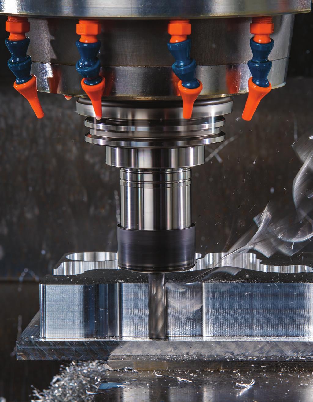
14 POW R PATH MACHINING REBOOTED. PRODUCTIVITY RELOADED. Push your productivity to the max with IMCO s POW R PATH IP/AP series end mills, designed specifically for high-efficiency machining (HEM). This dynamic combination of unique tool design features along with HEM tool paths increases your metal removal rates while decreasing wear on your tool. The proof is in the savings! 14

.")
15 IP/AP Series Features Features New tools for the new age of machining. Amplify the benefits of high-efficiency machining with POW R PATH IP/AP series cutting tools. Every aspect of POW R PATH end mills is optimized specifically for HEM methods to make sure you get every advantage this modern machining system can provide. The POW R PATH line is the most complete offering of end mills dedicated to HEM tool paths in the market, ranging from 7 to 13 flutes for steels and hi-temp alloys, and a 5-flute design for aluminum all available with or without the unique Chip Management System (CMS). IPT7 IPC7 IPT9 IPC9 IPT11 IPC11 IPT13 IPC13 APT5 APC5 NUMBER OF FLUTES Z7 Z7 Z9 Z11 Z13 Z5 Z5 END TYPES SQ CR CR CR CR SQ CR CR CR HELIX ANGLE COATING AlCrNX AlCrNX AlCrNX AlCrNX AlCrNX tac tac SHANK TYPES PLAIN PLAIN PLAIN PLAIN PLAIN PLAIN PLAIN APPLICATIONS HEM FINISH HEM HEM ROUGH FINISH MATERIAL(S) K P M S N 15
16 IPT7 POW R PATH For high-efficiency machining (HEM) in materials ranging from low carbon steels to hi-temp alloys. The IPT7 is the most versatile of the POW R PATH end mills. Engineered specifically for HEM tool paths, the IPT7 s unique design runs up to 4.5 x the tool diameter deep at elevated feed and metal removal rates. K P M S d2 Z7 SQ CR 40 l 1 (optional) l 2 R in: d1: / d2: / mm: d1: / d2: / AlCrNX d 1 PLAIN Shank Max Axial Depth by Corner Radius d1 d2 xd l2 l1 SQ.015 CR.030 CR.060 CR.090 CR.125 CR.187 CR.250 CR 3/16 3/16 1/4 1/4 3/8 3/8 1/2 1/2 5/8 5/8 3/4 3/4 1 1 D = Tool meter 2 3/ / /4 2-1/ / /4 2-1/ /4 2-1/ /16 2-1/ / /2 3-1/ /4 3-1/ /2 3-1/ / / /4 3-1/ / / /16 4-1/ / / /8 4-1/ / / /2 5-1/ /2 6-1/
17 Shank Max Axial Depth by Corner Radius d1 d2 xd l2 l1 SQ 0.5 CR 1.0 CR 1.5 CR 2.0 CR 3.0 CR D = Tool meter
18 IPC7 POW R PATH Z7 CR 40 AlCrNX PLAIN For high-efficiency machining (HEM) in materials ranging from low carbon steels to hi-temp alloys. Adds the benefits of the unique Chip Management System (CMS) to the versatility of the IPT7 design. Breaks up long, stringy chips, which eliminates recutting chips and chip packing, and allows for deep, free cutting tool movement in a variety of materials. K P M S d2 l 1 l 2 in: d1: / d2: / mm: d1: / d2: / d 1 R Shank Max Axial Depth by Corner Radius d1 d2 xd l2 l1.030 CR.060 CR 3/8 3/8 1/2 1/2 5/8 5/8 3/4 3/4 1 1 D = Tool meter 3 1-1/ /2 3-1/ /4 3-1/ /2 3-1/ / /4 3-1/ / / /16 4-1/ / / /8 4-1/ / / /2 5-1/ /2 6-1/

19 Shank Max Axial Depth d1 d2 xd l2 l1 1.0 CR D = Tool meter TOOL TIP HEM Tool Holder Recommendations. HEM tool paths reduce the amount of radial cutting forces that are exerted on the end mill, allowing for more aggressive speeds and feeds and longer tool life. The axial cutting forces, however, are increased and work to pull the end mill out of the holder and into the part. Using a holder with a high level of gripping power is critical for successful machining in HEM tool paths. It is also important to choose a holder that minimizes the run-out of the end mill. Holder Type Press Fit Shrink Fit Mechanical Chuck Hydraulic Chuck Advanced ER Collet Standard ER Collet Side Lock Holder Use in HEM Programming? Recommended Recommended Recommended Only if ADOC < 3xD Only if ADOC < 3xD Not recommended MUST keep run-out minimized 19
20 IPT7/IPC7 Application Guide Speed & Feed (inch) ISO Work Type of Axial Radial No. of Speed Feed (Inches per Tooth) Material Cut DOC DOC Flutes (SFM) 3/16 1/4 3/8 1/2 5/8 3/4 1 Peripheral - HEM 3 x D.1 x D K P M S D = Tool meter Gray ASTM-A48 Class 20, 25, 30, 35 & 40 Cast Iron Malleable Low Carbon Steels 38 Rc 1018, 1020, 12L14, 5120, 8620 Medium Carbon Steels 48 HRC 1045, 4140, 4340, 5140 Tool and Die Steels 48 Rc A2, D2, O1, S7, P20, H13 Martensitic & Ferritic Stainless Steels 410, 416, 440 Austenitic Stainless Steels, FeNi Alloys 303, 304, 316, Invar, Kovar Precipitation Hardening Stainless Steels 17-4, 15-5 Titanium Alloys 6Al-4V, Difficult-to-Machine Titanium Alloys Precipitation Hardening Stainless Steel M 13-8 Hastalloy, Waspalloy Inconel 718, Rene 88 HEM = High-efficiency machining Peripheral - HEM > 3 x D - 4 x D.08 x D Peripheral - HEM > 4 x D - 5 x D.08 x D Finish 3 x D.015 x D Peripheral - HEM 3 x D.08 x D Peripheral - HEM > 3-4 x D.08 x D Peripheral - HEM > 4-5 x D.08 x D Finish 3 x D.015 x D Peripheral - HEM 3 x D.08 x D Peripheral - HEM > 3-4 x D.08 x D Peripheral - HEM > 4-5 x D.08 x D Finish 3 x D.015 x D Peripheral - HEM 3 x D.08 x D Peripheral - HEM > 3-4 x D.08 x D Peripheral - HEM > 4-5 x D.08 x D Finish 3 x D.015 x D Peripheral - HEM 3 x D.08 x D Peripheral - HEM > 3-4 x D.08 x D Peripheral - HEM > 4-5 xd.08 x D Finish 3 x D.015 x D Peripheral - HEM 3 x D.08 x D Peripheral - HEM > 3-4 x D.08 x D Peripheral - HEM > 4-5 x D.08 x D Finish 3 x D.015 x D Peripheral - HEM 3 x D.08 x D Peripheral - HEM > 3-4 x D.08 x D Peripheral - HEM > 4-5 x D.07 x D Finish 3 x D.015 x D Peripheral - HEM 3 x D.08 x D Peripheral - HEM > 3-4 x D.08 x D Peripheral - HEM > 4-5 x D.07 x D Finish 3 x D.015 x D Peripheral - HEM 3 x D.1 x D Peripheral - HEM > 3-4 x D.08 x D Peripheral - HEM > 4-5 x D.08 x D Finish 3 x D.015 x D Peripheral - HEM 2.5 x D.08 x D Peripheral - HEM > x D.07 x D Peripheral - HEM > x D.06 x D Finish 3 x D.01 x D Peripheral - HEM 1.5 x D.08 x D Peripheral - HEM > x D.08 x D Peripheral - HEM > x D.06 x D Finish 2 x D.01 x D Peripheral - HEM 1.5 x D.07 x D Peripheral - HEM > x D.06 x D Peripheral - HEM > x D.06 x D Finish 2 x D.01 x D Approximately Equals Less Than or Equal To Greater Than or Equal To Multiply < > = Less Than Greater Than Equals Common Machining Formulas 20 SFM x 3.82 D RPM= SFM = RPM x D x.262 IPM = RPM x IPT x Z MRR = RDOC x ADOC x IPM M/min x D RPM= M/min= RPM x D x MMPM= RPM x MMPT x Z MRR = RDOC x ADOC x MMPM Axial DOC Radial DOC
21 IPT7/IPC7 Application Guide Speed & Feed (metric) ISO Work Type of Axial Radial No. of Speed Feed (MM per Tooth) Material Cut DOC DOC Flutes (M/min) Peripheral - HEM 3 x D.1 x D K P M S D = Tool meter Gray ASTM-A48 Class 20, 25, 30, 35 & 40 Cast Iron Malleable Low Carbon Steels 38 Rc 1018, 1020, 12L14, 5120, 8620 Medium Carbon Steels 48 HRC 1045, 4140, 4340, 5140 Tool and Die Steels 48 Rc A2, D2, O1, S7, P20, H13 Martensitic & Ferritic Stainless Steels 410, 416, 440 Austenitic Stainless Steels, FeNi Alloys 303, 304, 316, Invar, Kovar Precipitation Hardening Stainless Steels 17-4, 15-5 Titanium Alloys 6Al-4V, Difficult-to-Machine Titanium Alloys Precipitation Hardening Stainless Steel M 13-8 Hastalloy, Waspalloy Inconel 718, Rene 88 HEM = High-efficiency machining Peripheral - HEM > 3-4 x D.08 x D Peripheral - HEM > 4-5 x D.08 x D Finish 3 x D.015 x D Peripheral - HEM 3 x D.08 x D Peripheral - HEM > 3-4 x D.08 x D Peripheral - HEM > 4-5 x D.08 x D Finish 3 x D.015 x D Peripheral - HEM 3 x D.08 x D Peripheral - HEM > 3-4 x D.08 x D Peripheral - HEM > 4-5 x D.08 x D Finish 3 x D.015 x D Peripheral - HEM 3 x D.08 x D Peripheral - HEM > 3-4 x D.08 x D Peripheral - HEM > 4-5 x D.08 x D Finish 3 x D.015 x D Peripheral - HEM 3 x D.08 x D Peripheral - HEM > 3-4 x D.08 x D Peripheral - HEM > 4-5 x D.08 x D Finish 3 x D.015 x D Peripheral - HEM 3 x D.08 x D Peripheral - HEM > 3-4 x D.08 x D Peripheral - HEM > 4-5 x D.08 x D Finish 3 x D.015 x D Peripheral - HEM 3 x D.08 x D Peripheral - HEM > 3-4 x D.08 x D Peripheral - HEM > 4-5 x D.07 x D Finish 3 x D.015 x D Peripheral - HEM 3 x D.08 x D Peripheral - HEM > 3-4 x D.08 x D Peripheral - HEM > 4-5 x D.07 x D Finish 3 x D.015 x D Peripheral - HEM 3 x D.1 x D Peripheral - HEM > 3-4 x D.08 x D Peripheral - HEM > 4-5 x D.08 x D Finish 3 x D.015 x D Peripheral - HEM 2.5 x D.08 x D Peripheral - HEM > x D.07 x D Peripheral - HEM > x D.06 x D Finish 3 x D.01 x D Peripheral - HEM 1.5 x D.08 x D Peripheral - HEM > x D.08 x D Peripheral - HEM > x D.06 x D Finish 2 x D.01 x D Peripheral - HEM 1.5 x D.07 x D Peripheral - HEM > x D.06 x D Peripheral - HEM > x D.06 x D Finish 2 x D.01 x D D Z RPM SFM M/min IPM MMPM IPT MMPT MRR RDOC ADOC Tool meter Number of Flutes Revolutions per Minute Surface Feet per Minute Surface Meters per Minute Inches per Minute Millimeters per Minute Inch per Tooth Millimeters per Tooth Metal Removal Rate Radial Depth Axial Depth Technical Resources Information on tips and adjustments for the following milling operations can be found in our Technical Resources section beginning on page 125. HEM slotting Face milling Helical entry ramping Straight line ramping Long tool projection adjustments Ball nose milling adjustments Other helpful tips and calculations 21 21
22 IPT9 POW R PATH Z9 CR 36 AlCrNX PLAIN For high-efficiency machining (HEM) in materials ranging from low carbon steels to hi-temp alloys. The IPT9 POW R PATH end mill is engineered specifically for HEM tool paths with great core strength and 9 flutes for increased feed rates and excellent surface finishes. The unique design runs up to 3.5 x the tool diameter deep, generating high metal removal rates. d2 in: d1: / d2: / mm: d1: / d2: / l 1 l2 d 1 R K P M S Shank Max Axial Depth by Corner Radius d1 d2 xd l2 l1.015 CR.030 CR.060 CR.125 CR 1/4 1/4 3/8 3/8 1/2 1/2 5/8 5/8 3/4 3/4 1 1 D = Tool meter 2 1/ /8 2-1/ /4 2-1/ / /4 2-1/ /16 2-1/ / /16 3-1/ /4 3-1/ /2 3-1/ / /4 3-1/ / / /16 4-1/ / /8 4-1/ / / /2 5-1/ /2 6-1/
23 Shank Max Axial Depth by Corner Radius d1 d2 xd l2 l1 0.5 CR 1.0 CR 1.5 CR 3.0 CR D = Tool meter TOOL TIP Determining Power Requirements. It can be helpful to understand the power requirements for an application. The following formulas calculate spindle and motor horsepower and spindle torque. STEP 1: Metal Removal Rate (MRR) = (Tool Feed Rate) x Radial DOC x Axial DOC STEP 2: Spindle HP = Metal Removal Rate x UHP STEP 3: Motor HP = Spindle HP / Efficiency STEP 4: Spindle Torque (ft. lbs.) = (Spindle HP x 63,030) / RPM UHP Factors Rating Material Factor Aluminum 0.3 Cast iron 0.8 Carbon steel 1 Alloy steel 1.1 Mold steel 1.2 Tool steel 1.2 Stainless steel 1.5 Titanium 1.8 Hi-temp alloys 2 Efficiency Ratings Spindle Type % Direct drive 90% Gear drive 85% 2 Belt 70% 1 Belt 50% Average 80% 23
 to the versatility of the IPT9 design.")
24 IPC9 POW R PATH Z9 CR 36 AlCrNX PLAIN For high-efficiency machining (HEM) in materials ranging from low carbon steels to hi-temp alloys. Adds the benefits of the unique Chip Management System (CMS) to the versatility of the IPT9 design. Breaks up long, stringy chips, which eliminates recutting chips and chip packing, and allows for deep, free cutting tool movement in a variety of materials. d2 in: d1: / d2: / mm: d1: / d2: / l 1 l2 d 1 R K P M S Shank Max Axial Depth by Corner Radius d1 d2 xd l2 l1.030 CR.060 CR.125 CR 1/2 1/2 5/8 5/8 3/4 3/ /4 3-1/ /2 3-1/ / /4 3-1/ / / /16 4-1/ / /8 4-1/ / / /2 5-1/ /2 6-1/ d1 d2 xd l2 l1 1.0 CR 1.5 CR 3.0 CR D = Tool meter Shank Max Axial Depth by Corner Radius

25 25
26 IPT9/IPC9 Application Guide Speed & Feed (inch) ISO Work Type of Axial Radial No. of Speed Feed (Inches per Tooth) Material Cut DOC DOC Flutes (SFM) 1/4 3/8 1/2 5/8 3/4 1 Peripheral - HEM 3 x D.1 x D K P M S Gray ASTM-A48 Class 20, 25, 30, 35 & 40 Cast Iron Malleable Low Carbon Steels 38 Rc 1018, 1020, 12L14, 5120, 8620 Medium Carbon Steels 48 HRC 1045, 4140, 4340, 5140 Tool and Die Steels 48 Rc A2, D2, O1, S7, P20, H13 Martensitic & Ferritic Stainless Steels 410, 416, 440 Austenitic Stainless Steels, FeNi Alloys 303, 304, 316, Invar, Kovar Precipitation Hardening Stainless Steels 17-4, 15-5 Titanium Alloys 6Al-4V, Difficult-to-Machine Titanium Alloys Precipitation Hardening Stainless Steel M 13-8 Hastalloy, Waspalloy Inconel 718, Rene 88 Finish 2 x D.01 x D D = Tool meter HEM = High-efficiency machining Approximately Equals < Less Than > Greater Than = Equals Common Machining Formulas Peripheral - HEM > 3-4 x D.08 x D Peripheral - HEM > 4-5 x D.08 x D Finish 3 x D.015 x D Peripheral - HEM 3 x D.08 x D Peripheral - HEM > 3-4 x D.08 x D Peripheral - HEM > 4-5 x D.08 x D Finish 3 x D.015 x D Peripheral - HEM 3 x D.08 x D Peripheral - HEM > 3-4 x D.08 x D Peripheral - HEM > 4-5 x D.08 x D Finish 3 x D.015 x D Peripheral - HEM 3 x D.08 x D Peripheral - HEM > 3-4 x D.08 x D Peripheral - HEM > 4-5 x D.08 x D Finish 3 x D.015 x D Peripheral - HEM 3 x D.08 x D Peripheral - HEM > 3-4 x D.08 x D Peripheral - HEM > 4-5 x D.08 x D Finish 3 x D.015 x D Peripheral - HEM 3 x D.08 x D Peripheral - HEM > 3-4 x D.08 x D Peripheral - HEM > 4-5 x D.08 x D Finish 3 x D.015 x D Peripheral - HEM 3 x D.08 x D Peripheral - HEM > 3-4 x D.08 x D Peripheral - HEM > 4-5 x D.07 x D Finish 3 x D.015 x D Peripheral - HEM 3 x D.08 x D Peripheral - HEM > 3-4 x D.08 x D Peripheral - HEM > 4-5 x D.07 x D Finish 3 x D.015 x D Peripheral - HEM 3 x D.1 x D Peripheral - HEM > 3-4 x D.08 x D Peripheral - HEM > 4-5 x D.08 x D Finish 3 x D.015 x D Peripheral - HEM 2.5 x D.08 x D Peripheral - HEM > x D.07 x D Peripheral - HEM > x D.06 x D Finish 3 x D.01 x D Peripheral - HEM 1.5 x D.08 x D Peripheral - HEM > x D.08 x D Peripheral - HEM > x D.06 x D Finish 2 x D.01 x D Peripheral - HEM 1.5 x D.07 x D Peripheral - HEM > x D.06 x D Peripheral - HEM > x D.06 x D Less Than or Equal To Greater Than or Equal To Multiply 26 SFM x 3.82 D RPM= SFM = RPM x D x.262 IPM = RPM x IPT x Z MRR = RDOC x ADOC x IPM M/min x D RPM= M/min= RPM x D x MMPM= RPM x MMPT x Z MRR = RDOC x ADOC x MMPM Axial DOC Radial DOC
27 IPT9/IPC9 Application Guide Speed & Feed (metric) ISO Work Type of Axial Radial No. of Speed Feed (MM per Tooth) Material Cut DOC DOC Flutes (M/min) Peripheral - HEM 3 x D.1 x D K P M S D = Tool meter Gray ASTM-A48 Class 20, 25, 30, 35 & 40 Cast Iron Malleable Low Carbon Steels 38 Rc 1018, 1020, 12L14, 5120, 8620 Medium Carbon Steels 48 HRC 1045, 4140, 4340, 5140 Tool and Die Steels 48 Rc A2, D2, O1, S7, P20, H13 Martensitic & Ferritic Stainless Steels 410, 416, 440 Austenitic Stainless Steels, FeNi Alloys 303, 304, 316, Invar, Kovar Precipitation Hardening Stainless Steels 17-4, 15-5 Titanium Alloys 6Al-4V, Difficult-to-Machine Titanium Alloys Precipitation Hardening Stainless Steel M 13-8 Hastalloy, Waspalloy Inconel 718, Rene 88 HEM = High-efficiency machining Peripheral - HEM > 3-4 x D.08 x D Peripheral - HEM > 4-5 x D.08 x D Finish 3 x D.015 x D Peripheral - HEM 3 x D.08 x D Peripheral - HEM > 3-4 x D.08 x D Peripheral - HEM > 4-5 x D.08 x D Finish 3 x D.015 x D Peripheral - HEM 3 x D.08 x D Peripheral - HEM > 3-4 x D.08 x D Peripheral - HEM > 4-5 x D.08 x D Finish 3 x D.015 x D Peripheral - HEM 3 x D.08 x D Peripheral - HEM > 3-4 x D.08 x D Peripheral - HEM > 4-5 x D.08 x D Finish 3 x D.015 x D Peripheral - HEM 3 x D.08 x D Peripheral - HEM > 3-4 x D.08 x D Peripheral - HEM > 4-5 x D.08 x D Finish 3 x D.015 x D Peripheral - HEM 3 x D.08 x D Peripheral - HEM > 3-4 x D.08 x D Peripheral - HEM > 4-5 x D.08 x D Finish 3 x D.015 x D Peripheral - HEM 3 x D.08 x D Peripheral - HEM > 3-4 x D.08 x D Peripheral - HEM > 4-5 x D.07 x D Finish 3 x D.015 x D Peripheral - HEM 3 x D.08 x D Peripheral - HEM > 3-4 x D.08 x D Peripheral - HEM > 4-5 x D.07 x D Finish 3 x D.015 x D Peripheral - HEM 3 x D.1 x D Peripheral - HEM > 3-4 x D.08 x D Peripheral - HEM > 4-5 x D.08 x D Finish 3 x D.015 x D Peripheral - HEM 2.5 x D.08 x D Peripheral - HEM > x D.07 x D Peripheral - HEM > x D.06 x D Finish 3 x D.01 x D Peripheral - HEM 1.5 x D.08 x D Peripheral - HEM > x D.08 x D Peripheral - HEM > x D.06 x D Finish 2 x D.01 x D Peripheral - HEM 1.5 x D.07 x D Peripheral - HEM > x D.06 x D Peripheral - HEM > x D.06 x D Finish 2 x D.01 x D D Z RPM SFM M/min IPM MMPM IPT MMPT MRR RDOC ADOC Tool meter Number of Flutes Revolutions per Minute Surface Feet per Minute Surface Meters per Minute Inches per Minute Millimeters per Minute Inch per Tooth Millimeters per Tooth Metal Removal Rate Radial Depth Axial Depth Technical Resources Information on tips and adjustments for the following milling operations can be found in our Technical Resources section beginning on page 125. HEM slotting Face milling Helical entry ramping Straight line ramping Long tool projection adjustments Ball nose milling adjustments Other helpful tips and calculations 27

28 IPT11 POW R PATH For high-efficiency machining (HEM) in materials ranging from low carbon steels to hi-temp alloys. Built for results with 11 cutting edges to yield incredible feed rates. Engineered specifically for HEM tool paths, the IPT11 has a very thick core for extra stability when machining materials up to 3.5 x the tool diameter deep. K P M S d2 Z11 CR 34 AlCrNX PLAIN in: d1: / d2: / mm: d1: / d2: / l 1 l2 d 1 R Shank Max Axial Depth by Corner Radius d1 d2 xd l2 l1.030 CR.060 CR.125 CR 1/2 1/2 5/8 5/8 3/4 3/ /4 1-1/ /4 3-1/ /2 3-1/ / /4 3-1/ / / /16 4-1/ / /8 4-1/ / / /2 5-1/ /2 6-1/ /2 5-1/ /8 6-1/ Note that the IPT11 is not designed for light-duty machines and should only be run in machines with adequate spindle torque and horsepower. Shank Max Axial Depth by Corner Radius d1 d2 xd l2 l1 1.0 CR 1.5 CR 3.0 CR D = Tool meter
29 IPC11 POW R PATH Z11 CR 34 AlCrNX PLAIN For high-efficiency machining (HEM) in materials ranging from low carbon steels to hi-temp alloys. Adds the benefits of the unique Chip Management System (CMS) to the versatility of the IPT11 design. Breaks up long, stringy chips, which eliminates recutting chips and chip packing, and allows for deep, free cutting tool movement in a variety of materials. The results are great chip control and very high metal removal rates. d2 in: d1: / d2: / mm: d1: / d2: / l 1 l2 d 1 R K P M S Shank Max Axial Depth by Corner Radius d1 d2 xd l2 l1.030 CR.060 CR.125 CR 1/2 1/2 5/8 5/8 3/4 3/ /4 1-1/ /2 3-1/ / / / /16 4-1/ / /8 4-1/ / / /2 5-1/ /2 6-1/ /2 5-1/ /8 6-1/ Note that the IPC11 is not designed for light-duty machines and should only be run in machines with adequate spindle torque and horsepower. Shank Max Axial Depth by Corner Radius d1 d2 xd l2 l1 1.0 CR 1.5 CR 3.0 CR D = Tool meter
30 IPT11/IPC11 Application Guide Speed & Feed (inch) D = Tool meter 30 ISO Work Type of Axial Radial No. of Speed Material Cut DOC DOC Flutes (SFM) 1/2 5/8 3/ /4 Peripheral - HEM 2 x D.08 x D K P M S Gray ASTM-A48 Class 20, 25, 30, 35 & 40 Cast Iron Malleable Low Carbon Steels 38 Rc 1018, 1020, 12L14, 5120, 8620 Medium Carbon Steels 48 HRC 1045, 4140, 4340, 5140 Tool and Die Steels 48 Rc A2, D2, O1, S7, P20, H13 Martensitic & Ferritic Stainless Steels 410, 416, 440 Austenitic Stainless Steels, FeNi Alloys 303, 304, 316, Invar, Kovar Precipitation Hardening Stainless Steels 17-4, 15-5 Titanium Alloys 6Al-4V, Difficult-to-Machine Titanium Alloys Precipitation Hardening Stainless Steel M 13-8 Hastalloy, Waspalloy Inconel 718, Rene 88 HEM = High-efficiency machining Peripheral - HEM > 2-3 x D.07 x D Peripheral - HEM > x D.07 x D Peripheral - HEM > x D.065 x D Finish 3 x D.01 x D Peripheral - HEM 2 x D.07 x D Peripheral - HEM > 2-3 x D.07 x D Peripheral - HEM > x D.07 x D Peripheral - HEM > x D.07 x D Finish 3 x D.01 x D Peripheral - HEM 2 x D.07 x D Peripheral - HEM > 2-3 x D.07 x D Peripheral - HEM > x D.07 x D Peripheral - HEM > x D.07 x D Finish 3 x D.01 x D Peripheral - HEM 2 x D.07 x D Peripheral - HEM > 2-3 x D.07 x D Peripheral - HEM > x D.07 x D Peripheral - HEM > x D.07 x D Finish 3 x D.01 x D Peripheral - HEM 2 x D.06 x D Peripheral - HEM > 2-3 x D.06 x D Peripheral - HEM > x D.06 x D Peripheral - HEM > x D.06 x D Finish 3 x D.01 x D Peripheral - HEM 2 x D.06 x D Peripheral - HEM > 2-3 x D.06 x D Peripheral - HEM > x D.06 x D Peripheral - HEM > x D.06 x D Finish 3 x D.01 x D Peripheral - HEM 2 x D.06 x D Peripheral - HEM > 2-3 x D.06 x D Peripheral - HEM > x D.06 x D Peripheral - HEM > x D.06 x D Finish 3 x D.01 x D Peripheral - HEM 2 x D.06 x D Peripheral - HEM > 2-3 x D.06 x D Peripheral - HEM > x D.06 x D Peripheral - HEM > x D.06 x D Finish 3 x D.01 x D Peripheral - HEM 2 x D.06 x D Peripheral - HEM > 2-3 x D.06 x D Peripheral - HEM > x D.06 x D Peripheral - HEM > x D.06 x D Finish 3 x D.015 x D Peripheral - HEM 2 x D Peripheral - HEM > 2-3 x D Peripheral - HEM > x D Peripheral - HEM > x D Finish 3 x D.01 x D Peripheral - HEM 2 x D.07 X D Peripheral - HEM > 2-3 x D.065 x D Peripheral - HEM > x D.055 x D Peripheral - HEM > x D.055 x D Finish 3 x D.01 x D Peripheral - HEM 2 x D.065 x D Peripheral - HEM > 2-3 x D.06 x D Peripheral - HEM > x D.05 x D Peripheral - HEM > x D.05 x D Finish 3 x D.01 x D Approximately Equals Less Than or Equal To Greater Than or Equal To Multiply < > = Less Than Greater Than Equals
31 IPT11/IPC11 Application Guide Speed & Feed (metric) ISO Work Type of Axial Radial No. of Speed Material Cut DOC DOC Flutes (M/min) Peripheral - HEM 2 x D.08 x D K P M S Gray ASTM-A48 Class 20, 25, 30, 35 & 40 Cast Iron Malleable Low Carbon Steels 38 Rc 1018, 1020, 12L14, 5120, 8620 Medium Carbon Steels 48 HRC 1045, 4140, 4340, 5140 Tool and Die Steels 48 Rc A2, D2, O1, S7, P20, H13 Martensitic & Ferritic Stainless Steels 410, 416, 440 Austenitic Stainless Steels, FeNi Alloys 303, 304, 316, Invar, Kovar Precipitation Hardening Stainless Steels 17-4, 15-5 Titanium Alloys 6Al-4V, Difficult-to-Machine Titanium Alloys Precipitation Hardening Stainless Steel M 13-8 Hastalloy, Waspalloy Inconel 718, Rene 88 Peripheral - HEM > 2-3 x D.07 x D Peripheral - HEM > x D.07 x D Peripheral - HEM > x D.065 x D Finish 3 x D.01 x D Peripheral - HEM 2 x D.07 x D Peripheral - HEM > 2-3 x D.07 x D Peripheral - HEM > x D.07 x D Peripheral - HEM > x D.07 x D Finish 3 x D.01 x D Peripheral - HEM 2 x D.07 x D Peripheral - HEM > 2-3 x D.07 x D Peripheral - HEM > x D.07 x D Peripheral - HEM > x D.07 x D Finish 3 x D.01 x D Peripheral - HEM 2 x D.07 x D Peripheral - HEM > 2-3 x D.07 x D Peripheral - HEM > x D.07 x D Peripheral - HEM > x D.07 x D Finish 3 x D.01 x D Peripheral - HEM 2 x D.06 x D Peripheral - HEM > 2-3 x D.06 x D Peripheral - HEM > x D.06 x D Peripheral - HEM > x D.06 x D Finish 3 x D.01 x D Peripheral - HEM 2 x D.06 x D Peripheral - HEM > 2-3 x D.06 x D Peripheral - HEM > x D.06 x D Peripheral - HEM > x D.06 x D Finish 3 x D.01 x D Peripheral - HEM 2 x D.06 x D Peripheral - HEM > 2-3 x D.06 x D Peripheral - HEM > x D.06 x D Peripheral - HEM > x D.06 x D Finish 3 x D.01 x D Peripheral - HEM 2 x D.06 x D Peripheral - HEM > 2-3 x D.06 x D Peripheral - HEM > x D.06 x D Peripheral - HEM > x D.06 x D Finish 3 x D.01 x D Peripheral - HEM 2 x D.06 x D Peripheral - HEM > 2-3 x D.06 x D Peripheral - HEM > x D.06 x D Peripheral - HEM > x D.06 x D Finish 3 x D.015 x D Peripheral - HEM 2 x D Peripheral - HEM > 2-3 x D Peripheral - HEM > x D Peripheral - HEM > x D Finish 3 x D.01 x D Peripheral - HEM 2 x D.07 X D Peripheral - HEM > 2-3 x D.065 x D Peripheral - HEM > x D.055 x D Peripheral - HEM > x D.055 x D Finish 3 x D.01 x D Peripheral - HEM 2 x D.065 x D Peripheral - HEM > 2-3 x D.06 x D Peripheral - HEM > x D.05 x D Peripheral - HEM > x D.05 x D Finish 3 x D.01 x D D = Tool meter HEM = High-efficiency machining Information on tips and adjustments can be found in our Technical Resources section beginning on page

32 IPT13 POW R PATH For high-efficiency machining (HEM) in materials ranging from low carbon steels to hi-temp alloys. The IPT13 offers the most cutting edges available in the POW R PATH line. The 13 flutes yield incredible metal removal rates and tool life. Engineered specifically for HEM tool paths, the IPT13 has a very thick core for extra stability when machining materials up to 3.5 x the tool diameter deep. d2 Z13 CR 30 AlCrNX PLAIN in: d1: / d2: / mm: d1: / d2: / l 1 l2 d 1 R K P M S Shank Max Axial Depth by Corner Radius d1 d2 xd l2 l1.030 CR.060 CR.125 CR 1/2 1/2 5/8 5/8 3/4 3/ /4 1-1/ /4 3-1/ /2 3-1/ / /4 3-1/ / / /16 4-1/ / /8 4-1/ / / /2 5-1/ /2 6-1/ /2 5-1/ /8 6-1/ Note that the IPT13 is not designed for light-duty machines and should only be run in machines with adequate spindle torque and horsepower. Shank Max Axial Depth by Corner Radius d1 d2 xd l2 l1 1.0 CR 1.5 CR 3.0 CR D = Tool meter
33 IPC13 POW R PATH Z13 CR 30 AlCrNX PLAIN For high-efficiency machining (HEM) in materials ranging from low carbon steels to hi-temp alloys. Adds the benefits of the unique Chip Management System (CMS) to the versatility of the IPT13 design. Breaks up long, stringy chips, which eliminates recutting chips and chip packing, and allows for deep, free cutting tool movement in a variety of materials. The results are great chip control and very high metal removal rates. d2 in: d1: / d2: / mm: d1: / d2: / l 1 l2 d 1 R K P M S Shank Max Axial Depth by Corner Radius d1 d2 xd l2 l1.030 CR.060 CR.125 CR 1/2 1/2 5/8 5/8 3/4 3/ /4 1-1/ /2 3-1/ / / / /16 4-1/ / /8 4-1/ / / /2 5-1/ /2 6-1/ /2 5-1/ /8 6-1/ Note that the IPC13 is not designed for light-duty machines and should only be run in machines with adequate spindle torque and horsepower. Shank Max Axial Depth by Corner Radius d1 d2 xd l2 l1 1.0 CR 1.5 CR 3.0 CR D = Tool meter
34 IPT13/IPC13 Application Guide Speed & Feed (inch) D = Tool meter 34 ISO Work Type of Axial Radial No. of Speed Feed (Inches per Tooth) Material Cut DOC DOC Flutes (SFM) 1/2 5/8 3/ /4 Peripheral - HEM 2 x D.07 x D K P M S Gray ASTM-A48 Class 20, 25, 30, 35 & 40 Cast Iron Malleable Low Carbon Steels 38 Rc 1018, 1020, 12L14, 5120, 8620 Medium Carbon Steels 48 HRC 1045, 4140, 4340, 5140 Tool and Die Steels 48 Rc A2, D2, O1, S7, P20, H13 Martensitic & Ferritic Stainless Steels 410, 416, 440 Austenitic Stainless Steels, FeNi Alloys 303, 304, 316, Invar, Kovar Precipitation Hardening Stainless Steels 17-4, 15-5 Titanium Alloys 6Al-4V, Difficult-to-Machine Titanium Alloys Precipitation Hardening Stainless Steels M 13-8 Hastalloy, Waspalloy Inconel 718, Rene 88 HEM = High-efficiency machining Peripheral - HEM > 2-3 x D.07 x D Peripheral - HEM > x D.07 x D Peripheral - HEM > x D.06 x D Finish 3 x D.01 x D Peripheral - HEM 2 x D.07 x D Peripheral - HEM > 2-3 x D.07 x D Peripheral - HEM > x D.07 x D Peripheral - HEM > x D.07 x D Finish 3 x D.01 x D Peripheral - HEM 2 x D.07 x D Peripheral - HEM > 2-3 x D.07 x D Peripheral - HEM > x D.07 x D Peripheral - HEM > x D.07 x D Finish 3 x D.01 x D Peripheral - HEM 2 x D.06 x D Peripheral - HEM > 2-3 x D.06 x D Peripheral - HEM > x D.05 x D Peripheral - HEM > x D.05 x D Finish 3 x D.01 x D Peripheral - HEM 2 x D.06 x D Peripheral - HEM > 2-3 x D.06 x D Peripheral - HEM > x D.05 x D Peripheral - HEM > x D.05 x D Finish 3 x D.01 x D Peripheral - HEM 2 x D.06 x D Peripheral - HEM > 2-3 x D.06 x D Peripheral - HEM > x D.06 x D Peripheral - HEM > x D.06 x D Finish 3 x D.01 x D Peripheral - HEM 2 x D.06 x D Peripheral - HEM > 2-3 x D.06 x D Peripheral - HEM > x D.05 x D Peripheral - HEM > x D.05 x D Finish 3 x D.01 x D Peripheral - HEM > 2-3 x D.06 x D Peripheral - HEM > x D.05 x D Peripheral - HEM > x D.05 x D Finish 3 x D.01 x D Peripheral - HEM 2 x D.08 x D Peripheral - HEM > 2-3 x D.07 x D Peripheral - HEM > x D.06 x D Peripheral - HEM > x D.06 x D Finish 3 x D.015 x D Peripheral - HEM 2 x D Peripheral - HEM > 2-3 x D Peripheral - HEM > x D Peripheral - HEM > x D Finish 3 x D.01 x D Peripheral - HEM 2 x D.07 X D Peripheral - HEM > 2-3 x D.065 x D Peripheral - HEM > x D.055 x D Peripheral - HEM > x D.05 x D Finish 3 x D.01 x D Peripheral - HEM 2 x D.06 x D Peripheral - HEM > 2-3 x D.05 x D Peripheral - HEM > x D.05 x D Peripheral - HEM > x D.04 x D Finish 3 x D.01 x D Approximately Equals Less Than or Equal To Greater Than or Equal To Multiply < > = Less Than Greater Than Equals
35 IPT13/IPC13 Application Guide Speed & Feed (metric) ISO Work Type of Axial Radial No. of Speed Feed (MM per Tooth) Material Cut DOC DOC Flutes (M/min) Peripheral - HEM 2 x D.07 x D K P M S D = Tool meter Gray ASTM-A48 Class 20, 25, 30, 35 & 40 Cast Iron Malleable Low Carbon Steels 38 Rc 1018, 1020, 12L14, 5120, 8620 Medium Carbon Steels 48 HRC 1045, 4140, 4340, 5140 Tool and Die Steels 48 Rc A2, D2, O1, S7, P20, H13 Martensitic & Ferritic Stainless Steels 410, 416, 440 Austenitic Stainless Steels, FeNi Alloys 303, 304, 316, Invar, Kovar Precipitation Hardening Stainless Steels 17-4, 15-5 Titanium Alloys 6Al-4V, Difficult-to-Machine Titanium Alloys Precipitation Hardening Stainless Steel M 13-8 Hastalloy, Waspalloy Inconel 718, Rene 88 HEM = High-efficiency machining Peripheral - HEM > 2-3 x D.07 x D Peripheral - HEM > x D.07 x D Peripheral - HEM > x D.06 x D Finish 3 x D.01 x D Peripheral - HEM 2 x D.07 x D Peripheral - HEM > 2-3 x D.07 x D Peripheral - HEM > x D.07 x D Peripheral - HEM > x D.07 x D Finish 3 x D.01 x D Peripheral - HEM 2 x D.07 x D Peripheral - HEM > 2-3 x D.07 x D Peripheral - HEM > x D.07 x D Peripheral - HEM > x D.07 x D Finish 3 x D.01 x D Peripheral - HEM 2 x D.06 x D Peripheral - HEM > 2-3 x D.06 x D Peripheral - HEM > x D.05 x D Peripheral - HEM > x D.05 x D Finish 3 x D.01 x D Peripheral - HEM 2 x D.06 x D Peripheral - HEM > 2-3 x D.06 x D Peripheral - HEM > x D.05 x D Peripheral - HEM > x D.05 x D Finish 3 x D.01 x D Peripheral - HEM 2 x D.06 x D Peripheral - HEM > 2-3 x D.06 x D Peripheral - HEM > x D.06 x D Peripheral - HEM > x D.06 x D Finish 3 x D.01 x D Peripheral - HEM 2 x D.06 x D Peripheral - HEM > 2-3 x D.06 x D Peripheral - HEM > x D.05 x D Peripheral - HEM > x D.05 x D Finish 3 x D.01 x D Peripheral - HEM 2 x D.06 x D Peripheral - HEM > 2-3 x D.06 x D Peripheral - HEM > x D.05 x D Peripheral - HEM > x D.05 x D Finish 3 x D.01 x D Peripheral - HEM 2 x D.08 x D Peripheral - HEM > 2-3 x D.07 x D Peripheral - HEM > x D.06 x D Peripheral - HEM > x D.06 x D Finish 3 x D.015 x D Peripheral - HEM 2 x D Peripheral - HEM > 2-3 x D Peripheral - HEM > x D Peripheral - HEM > x D Finish 3 x D.01 x D Peripheral - HEM 2 x D.07 X D Peripheral - HEM > 2-3 x D.065 x D Peripheral - HEM > x D.055 x D Peripheral - HEM > x D.05 x D Finish 3 x D.01 x D Peripheral - HEM 2 x D.06 x D Peripheral - HEM > 2-3 x D.05 x D Peripheral - HEM > x D.05 x D Peripheral - HEM > x D.04 x D Finish 3 x D.01 x D Information on tips and adjustments can be found in our Technical Resources section beginning on page
36 APT5 POW R PATH For high-efficiency machining (HEM) in aluminum alloys. The APT5 is the POW R PATH tool that applies to aluminum alloys the same HEM tool paths that work very well in ferrous materials. Engineered with both a solid core for stability and chip evacuation space for high feed rates. The unique cutting edge design combined with 5 flutes and the extra-durable tac coating generates incredibly high metal removal rates. d2 Z5 SQ CR 35 tac PLAIN l 1 l 2 in: d1: / d2: / mm: d1: / d2: / d 1 (optional) R N Shank Max Axial Depth by Corner Radius d1 d2 xd l2 l1 SQ.015 CR.030 CR.060 CR.090 CR.125 CR.187 CR.250 CR 1/4 1/4 3/8 3/8 1/2 1/2 5/8 5/8 3/4 3/4 1 1 D = Tool meter 2 1/ /4 2-1/ /4 2-1/ / /2 3-1/ /4 3-1/ /2 3-1/ / /4 3-1/ / / / /8 4-1/ / /

37 Shank Max Axial Depth by Corner Radius d1 d2 xd l2 l1 SQ 0.5 CR 1.0 CR 1.5 CR 2.0 CR 2.5 CR 3.0 CR 4.0 CR D = Tool meter TOOL TIP AP5: Pushing the Limits of Productivity. The APT5 and APC5 POW R PATH end mills bring the concept of HEM tool paths to machining aluminum alloys. The unique AP design cleaves through aluminum at very high metal removal rates without needing a lot of horsepower, making the AP end mills extremely versatile. Adding to the AP s versatility are: Many corner radius options. 5 flutes for excellent surface finishes. The tac coating that protects the cutting edges to ensure long tool life even in high-silicon aluminums. The Chip Management System (CMS) option that stops chip pollution by breaking the cut material into manageable lengths, eliminating chip packing. 37

 R N Shank Reach LBS by Corner Radius d1 d2 l2 l3 l1 SQ.015 CR.030 CR.060 CR.090 CR.125 CR.")
38 APT5N POW R PATH For high-efficiency machining (HEM) in aluminum alloys. Adding a necked shank to the APT5 design offers a highperformance tool that permits clearance in deeper cavities and easier machining against tight walls. Neck relief and short flute length combine to increase end mill stability in the cut for more precise tolerances. Great for work in pockets. Z5 SQ CR 35 NECK tac PLAIN d2 in: d1: / d2: / mm: d1: / d2: / l 1 l 3 l 2 d1 (optional) R N Shank Reach LBS by Corner Radius d1 d2 l2 l3 l1 SQ.015 CR.030 CR.060 CR.090 CR.125 CR.250 CR 1/4 1/4 3/8 3/8 1/2 1/2 5/8 5/8 3/4 3/ /8 7/8 2-1/ /8 1-3/ /8 2-1/ /16 1-1/16 2-1/ /16 1-1/ /16 2-3/ /4 1-1/ /4 2-1/ /4 3-1/ /4 4-1/ /16 1-9/ /16 2-3/ /16 3-3/ /8 1-5/ /8 2-1/ /8 3-1/ /2 2-3/ /2 3-1/ /2 4-1/ Shank Reach LBS by Corner Radius d1 d2 l2 l3 l1 SQ 0.5 CR 1.0 CR 1.5 CR 2.0 CR 2.5 CR 3.0 CR 4.0 CR D = Tool meter 38

39 APC5 POW R PATH For high-efficiency machining (HEM) in aluminum alloys. Adds the benefits of the unique Chip Management System (CMS) to the versatility of the APT5 design. Breaks up long, stringy chips, which eliminates recutting chips and chip packing, and allows for deep, free cutting tool movement in aluminum. The results are great chip control and very high metal removal rates. Z5 SQ CR 35 tac PLAIN d2 l 1 l 2 in: d1: / d2: / mm: d1: / d2: / d d1 (optional) R N Shank Max Axial Depth by Corner Radius d1 d2 xd l2 l1 SQ.015 CR.030 CR 3/8 3/8 1/2 1/2 5/8 5/8 3/4 3/ / /2 3-1/ /4 3-1/ /2 3-1/ / /4 3-1/ / / /8 4-1/ / / Shank Max Axial Depth by Corner Radius d1 d2 xd l2 l1 SQ 0.5 CR 1.0 CR D = Tool meter
40 APT5/APC5 Application Guide Speed & Feed (inch) ISO N D = Tool meter Aluminum Alloys 6061, 7075, 2024 Work Type of Axial Radial No. of Speed Feed (Inch per Tooth) Material Cut DOC DOC Flutes (SFM) 1/4 3/8 1/2 5/8 3/4 1 Slotting 1 x D 1 x D Peripheral - HEM 2 x D.25 x D Peripheral - HEM > x D.25 x D Peripheral - HEM > x D.25 x D HEM = High-efficiency machining Peripheral - HEM > x D.25 x D Peripheral - HEM > x D.20 x D Peripheral - Rough 2 x D.45 x D Peripheral - Rough > 2-3 x D.375 x D Peripheral - Rough > 3-4 x D.35 x D Finish 4 x D.01 x D APT5/APC5 Application Guide Speed & Feed (metric) ISO N D = Tool meter Work Material Aluminum Alloys 6061, 7075, 2024 HEM = High-efficiency machining Type of Axial Radial Number Speed Feed (MM per Tooth) Cut DOC DOC of Flutes (M/min) Slotting 1 x D 1 x D Peripheral - HEM 2 x D.25 x D Peripheral - HEM > x D.25 x D Peripheral - HEM > x D.25 x D Peripheral - HEM > x D.25 x D Peripheral - HEM > x D.20 x D Peripheral - Rough 2 x D.45 x D Peripheral - Rough > 2-3 x D.375 x D Peripheral - Rough > 3-4 x D.35 x D Finish 4 x D.01 x D Approximately Equals Less Than or Equal To Greater Than or Equal To Multiply < > = Less Than Greater Than Equals Common Machining Formulas Technical Resources 40 Axial DOC SFM x 3.82 D RPM= SFM = RPM x D x.262 IPM = RPM x IPT x Z MRR = RDOC x ADOC x IPM Radial DOC M/min x D RPM= M/min= RPM x D x MMPM= RPM x MMPT x Z MRR = RDOC x ADOC x MMPM D Z RPM SFM M/min IPM MMPM IPT MMPT MRR RDOC ADOC Tool meter Number of Flutes Revolutions per Minute Surface Feet per Minute Surface Meters per Minute Inches per Minute Millimeters per Minute Inch per Tooth Millimeters per Tooth Metal Removal Rate Radial Depth Axial Depth Information on tips and adjustments for the following milling operations can be found in our Technical Resources section beginning on page 125. HEM slotting Face milling Helical entry ramping Straight line ramping Long tool projection adjustments Ball nose milling adjustments Other helpful tips and calculations


41 AFC/IFC POW R PATH The AFC and IFC end mills are designed to machine deep reach, straight walls with minimum taper in aluminum (AFC) and in steels and hi-temp alloys (IFC). Created with the ultimate core thickness for reduced deflection to address difficult finish requirements. Standard dimensions are shown below, but IMCO recognizes that all machine parts are unique so they require unique tools to finish mill. Variations of the AFC and IFC end mills with different flute lengths and overall lengths are possible. Contact IMCO for quotations with the specifications needed to finish your application. N Shank Max Axial by Corner Radius (R) Depth d1 d2 xd l2 l1.030 CR.060 CR 1/2 1/2 5/8 5/8 3/4 3/ / /4 6-1/ / d2 AFC l 1 l 2 d d1 R D = Tool meter K P M S Shank Max Axial Depth by Corner Radius d1 d2 xd l2 l1.030 CR.060 CR 1/2 1/2 5/8 5/8 3/4 3/ / /4 6-1/ / d2 IFC l 1 l 2 d1 R D = Tool meter 41

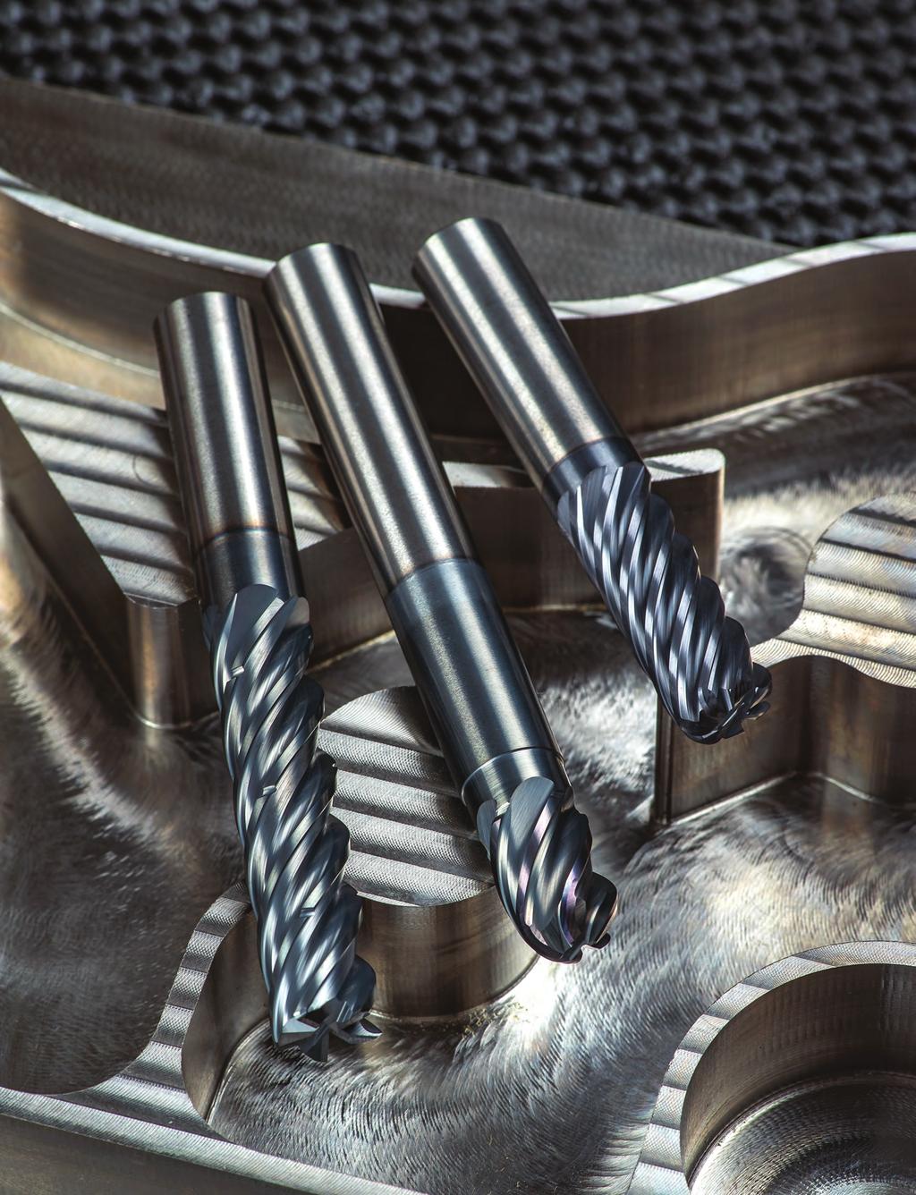
42 enduro MUSCLE TO HUSTLE IN TITANIUM AND STAINLESS STEELS Advanced high-shear cutting edges and amazing corner strength make enduro end mills the best choice for milling hard-to-machine materials, whether you use high-efficiency machining or traditional techniques. 42


43 M5 Series Features MUSCLE TO HUSTLE. Truly a go-to tool for a wide range of applications, enduro end mills are the ultimate combination of strength and flexibility. A solid core, reinforced cutting edges, variable indexed flutes and an advanced coating all come together in the M525 and M527 series to create an everyday high-performance end mill that excels in both traditional and high-efficiency milling tool paths. M525 M525C M525N M527 M527C M503 NUMBER OF FLUTES Z5 Z5 Z5 Z7 Z7 Z3 SQ SQ SQ SQ SQ SQ END TYPES CR CR CR CR CR CR BN BN HELIX ANGLE COATING AlCrNX AlCrNX AlCrNX AlCrNX AlCrNX AlTiN SHANK TYPES PLAIN PLAIN PLAIN PLAIN PLAIN PLAIN NECK HEM HEM ROUGH HEM HEM ROUGH APPLICATIONS ROUGH ROUGH FINISH ROUGH ROUGH FINISH FINISH FINISH MATERIAL(S) K P M S P M 43
44 M525 enduro For high-performance machining in materials ranging from low carbon steels to titanium. Engineered for both speed and tool life, the M525 series is extremely versatile. It optimizes tool performance in many materials and in many application environments, from short runs in job shops to long production runs. d2 Z5 SQ CR l 1 BN 40 AlCrNX PLAIN l2 d 1 (optional) R K P M S in: d1: / d2: / mm: d1: / d2: / Shank by Corner Radius d1 d2 l2 l1 SQ.015 CR.030 CR.060 CR.090 CR.125 CR.187 CR.250 CR BN 1/8 1/8 3/16 3/16 1/4 1/4 5/16 5/16 3/8 3/8 7/16 7/16 1/2 1/2 5/8 5/8 3/4 3/ /4 1-1/ /2 1-1/ /4 2-1/ / / /4 2-1/ / /4 2-1/ / / /16 2-1/ / / / / / /8 3-1/ / /8 2-1/ / /8 2-1/ / / / / / / / /8 3-1/ / / / / / / / / / / / / /

45 Shank by Corner Radius d1 d2 l2 l1 SQ 0.5 CR 0.75 CR 1.0 CR 1.5 CR 2.0 CR 3.0 CR 4.0 CR 5.0 CR TOOL TIP How Do You Spell Versatility? e-n-d-u-r-o. The M5 enduro series of end mills are the definition of versatility. The 5- and 7-flute designs are made to rough and finish in traditional tool paths and in high-efficiency machining techniques. From job shops to high-production environments, the M5 is the go-to tool that saves you time and money. Many corner radius options. Optional necked shanks for pocket milling. Chip Managment System (CMS) to stop chip pollution for free cutting machining. Advanced grinds and coatings to machine carbon steels, stainless steels, titanium and hi-temp alloys. 45
46 M525C enduro For high-performance machining in materials ranging from low carbon steels to titanium. Adds the benefits of the unique Chip Management System (CMS) to the versatility of the M525 design. Breaks up long, stringy chips, which eliminates recutting chips and chip packing, and allows for free cutting tool movement in a variety of materials. d2 Z5 SQ l 1 CR in: d1: / d2: / mm: d1: / d2: / AlCrNX PLAIN l2 d 1 (optional) R K P M S Shank by Corner Radius d1 d2 l2 l1 SQ.015 CR.030 CR.060 CR.120 CR 1/2 1/2 5/8 5/8 3/4 3/ / / / / / / / / / / / / Shank by Corner Radius d1 d2 l2 l1 SQ 0.75 CR 1.0 CR 1.5 CR


47 M525N enduro Z5 SQ CR BN 40 NECK AlCrNX PLAIN For high-performance machining in materials ranging from low carbon steels to titanium. Adding a necked shank to the M525 design offers a high-performance tool that permits clearance in deeper cavities and easier machining against tight walls. Neck relief and short flute length combine to increase end mill stability in the cut for more precise tolerances. Great for work in pockets. d2 l 1 l 3 l 2 d 1 (optional) R K P M S in: d1: / d2: / mm: d1: / d2: / Shank Reach LBS by Corner Radius d1 d2 l2 l3 l1 SQ.015 CR.030 CR.060 CR.120 CR.250 CR BN 1/4 1/4 3/8 3/8 3/8 1/2 1/2 1/2 5/8 5/8 5/8 3/4 3/4 3/ /4 1-1/8 2-1/ / / / / / / / / / / / / / / / / / / Shank Reach LBS by Corner Radius d1 d2 l2 l3 l1 SQ 0.5 CR 1.0 CR 1.5 CR 2.0 CR 3.0 CR BN
48 M525 Application Guide Speed & Feed (inch) ISO Work Type of Axial Radial No. of Speed Feed (Inches per Tooth) Material Cut DOC DOC Flutes (SFM) 1/8 3/16 1/4 5/16 3/8 7/16 1/2 5/8 3/4 1 K P M S D = Tool meter Cast Iron Gray ASTM-A48 Class 20, 25, 30, 35 & 40 Cast Iron Malleable Low Carbon Steels 38 Rc 1018, 1020, 12L14, 5120, 8620 Medium Carbon Steels 48 HRC 1045, 4140, 4340, 5140 Tool and Die Steels 48 Rc A2, D2, O1, S7, P20, H13 Martensitic & Ferritic Stainless Steels 410, 416, 440 Austenitic Stainless Steels, FeNi Alloys 303, 304, 316, Invar, Kovar Precipitation Hardening Stainless Steels 17-4, 15-5 Titanium Alloys 6Al-4V, Difficult-to-Machine Titanium Alloys Precipitation Hardening Stainless Steels M 13-8 Slotting.5 x D 1 x D Peripheral - Rough 1.25 x D.3 x D Finish 2 x D.015 x D Slotting.5 x D 1 x D Peripheral - Rough 1.25 x D.3 x D Peripheral - HEM* 3 x D.05 x D Finish 2 x D.015 x D Slotting.5 x D 1 x D Peripheral - Rough 1.25 x D.3 x D Peripheral - HEM* 3 x D.07 x D Finish 2 x.015 x D Slotting.5 x D 1 x D Peripheral - Rough 1.25 x D.3 x D Peripheral - HEM* 3 x D.05 x D Finish 2 x D.015 x D Slotting.5 x D 1 x D Peripheral - Rough 1.25 x D.3 x D Peripheral - HEM* 3 x D.05 x D Finish 2 x D.015 x D Slotting.5 x D 1 x D Peripheral - Rough 1.25 x D.3 x D Peripheral - HEM* 3 x D.05 x D Finish 2 x D.015 x D Slotting.5 x D 1 x D Peripheral - Rough 1.25 x D.3 x D Peripheral - HEM* 3 x D.05 x D Finish 2 x D.015 x D Slotting.5 x D 1 x D Peripheral - Rough 1.25 x D.3 x D Peripheral - HEM* 3 x D.05 x D Finish 1.5 x D.015 x D Slotting.5 x D 1 x D Peripheral - Rough 1 x D.3 x D Peripheral - HEM* 3 x D.05 x D Finish 1.5 x D.015 x D Slotting.25 x D 1 x D Peripheral - Rough 1 x D.25 x D Peripheral - HEM* 3 x D.05 x D Finish 1.5 x D.01 x D * HEM = High-efficiency machining (chip thinning calculations have already been applied to HEM parameters shown). Approximately Equals Less Than or Equal To Greater Than or Equal To Multiply < > = Less Than Greater Than Equals Common Machining Formulas SFM x 3.82 D RPM= SFM = RPM x D x.262 IPM = RPM x IPT x Z MRR = RDOC x ADOC x IPM M/min x D RPM= M/min= RPM x D x MMPM= RPM x MMPT x Z MRR = RDOC x ADOC x MMPM Axial DOC Radial DOC 48
49 M525 Application Guide Speed & Feed (metric) ISO Work Type of Axial Radial No. of Speed Feed (MM per Tooth) Material Cut DOC DOC Flutes (M/min) K P M S D = Tool meter Cast Iron Gray ASTM-A48 Class 20, 25, 30, 35 & 40 Cast Iron Malleable Low Carbon Steels 38 Rc 1018, 1020, 12L14, 5120, 8620 Medium Carbon Steels 48 HRC 1045, 4140, 4340, 5140 Tool and Die Steels 48 Rc A2, D2, O1, S7, P20, H13 Martensitic & Ferritic Stainless Steels 410, 416, 440 Austenitic Stainless Steels, FeNi Alloys 303, 304, 316, Invar, Kovar Precipitation Hardening Stainless Steels 17-4, 15-5 Titanium Alloys 6Al-4V, Difficult-to-Machine Titanium Alloys Precipitation Hardening Stainless Steels M 13-8 Slotting.5 x D 1 x D Peripheral - Rough 1.25 x D.3 x D Finish 2 x D.015 x D Slotting.5 x D 1 x D Peripheral - Rough 1.25 x D.3 x D Peripheral - HEM* 3 x D.05 x D Finish 2 x D.015 x D Slotting.5 x D 1 x D Peripheral - Rough 1.25 x D.3 x D Peripheral - HEM* 3 x D.07 x D Finish 2 x.015 x D Slotting.5 x D 1 x D Peripheral - Rough 1.25 x D.3 x D Peripheral - HEM* 3 x D.05 x D Finish 2 x D.015 x D Slotting.5 x D 1 x D Peripheral - Rough 1.25 x D.3 x D Peripheral - HEM* 3 x D.05 x D Finish 2 x D.015 x D Slotting.5 x D 1 x D Peripheral - Rough 1.25 x D.3 x D Peripheral - HEM* 3 x D.05 x D Finish 2 x D.015 x D Slotting.5 x D 1 x D Peripheral - Rough 1.25 x D.3 x D Peripheral - HEM* 3 x D.05 x D Finish 2 x D.015 x D Slotting.5 x D 1 x D Peripheral - Rough 1.25 x D.3 x D Peripheral - HEM* 3 x D.05 x D Finish 1.5 x D.015 x D Slotting.5 x D 1 x D Peripheral - Rough 1 x D.3 x D Peripheral - HEM* 3 x D.05 x D Finish 1.5 x D.015 x D Slotting.25 x D 1 x D Peripheral - Rough 1 x D.25 x D Peripheral - HEM* 3 x D.05 x D Finish 1.5 x D.01 x D * HEM = High-efficiency machining (chip thinning calculations have already been applied to HEM parameters shown). D Z RPM SFM M/min IPM MMPM IPT MMPT MRR RDOC ADOC Tool meter Number of Flutes Revolutions per Minute Surface Feet per Minute Surface Meters per Minute Inches per Minute Millimeters per Minute Inch per Tooth Millimeters per Tooth Metal Removal Rate Radial Depth Axial Depth Technical Resources Information on tips and adjustments for the following milling operations can be found in our Technical Resources section beginning on page 125. HEM slotting Face milling Helical entry ramping Straight line ramping Long tool projection adjustments Ball nose milling adjustments Other helpful tips and calculations 49

50 M527 enduro For high-performance machining in materials ranging from low carbon steels to titanium. The M527 takes the best features of the M525 and adds two cutting edges to improve metal removal rates especially in HEM tool paths without losing any versatility. The 7 cutting edges also make the M527 an excellent choice for finishing applications. d2 Z7 SQ CR l 1 40 l2 AlCrNX in: d1: / d2: / mm: d1: / d2: / d 1 PLAIN (optional) R K P M S Shank by Corner Radius d1 d2 l2 l1 SQ.015 CR.030 CR.060 CR.125 CR 3/8 3/8 1/2 1/2 5/8 5/8 3/4 3/ / /8 2-1/ / /8 2-1/ / /8 3-1/ / / / /8 3-1/ / / / / / / / / / / / Shank by Corner Radius d1 d2 l2 l1 SQ 0.5 CR 1.0 CR 1.5 CR

 R K P M S Shank by Corner Radius d1 d2 l2 l1 SQ.015 CR.030 CR.")

51 M527C enduro For high-performance machining in materials ranging from low carbon steels to titanium. Adds the benefits of the unique Chip Management System (CMS) to the versatility of the M527 design. Breaks up long, stringy chips, which eliminates recutting chips and chip packing, and allows for free cutting tool movement in a variety of materials. The results are great chip control and very high metal removal rates. Z7 SQ CR d2 l 1 40 AlCrNX in: d1: / d2: / l2 PLAIN d 1 (optional) R K P M S Shank by Corner Radius d1 d2 l2 l1 SQ.015 CR.030 CR.060 CR 1/2 1/2 5/8 5/8 3/4 3/ / / / / / / / / / / / TOOL TIP CMS: Stop Chip Pollution. Controlling chip size and clearing the chips from the cutting zone are important when machining in all tools paths, but they become critical in traditional slotting and when using HEM paths. IMCO s CMS is a unique edge treatment design that breaks materials into smaller, more manageable chips. CMS helps improve the effectiveness of the coolant or air blasts in evacuating the chips from the cutting zone, preventing chip packing and recutting improving tool life and performance. Chip pollution caused by a non-cms tool. 51
52 M527 Application Guide Speed & Feed (inch) ISO Work Type of Axial Radial No. of Speed Feed (Inch per Tooth) Material Cut DOC DOC Flutes (SFM) 3/8 1/2 5/8 3/4 1 K P M S D = Tool meter * HEM= High-efficiency machining (chip Slotting thinning calculations.25 have x Dalready been 1 x applied D to HEM 7 parameters 200 shown) Difficult-to-Machine Titanium Alloys Peripheral - Rough 1 x D.25 x D Precipitation Hardening Stainless Steel Peripheral - HEM* 3 x D.05 x D M 13-8 Finish 1.5 x D.01 x D D = Tool meter Cast Iron Gray Cast Iron Low Carbon Steels 38 Rc 1018, 1020, 12L14, 5120, 8620 Medium Carbon Steels 48 HRC 1045, 4140, 4340, 5140 Tool and Die Steels 48 Rc A2, D2, O1, S7, P20, H13 Martensitic & Ferritic Stainless Steels 410, 416, 440 Austenitic Stainless Steels, FeNi Alloys 303, 304, 316, Invar, Kovar Precipitation Hardening Stainless Steels 17-4, 15-5 Titanium Alloys 6Al-4V, Slotting.5 x D 1 x D Peripheral - Rough 1.25 x D.3 x D Finish 2 x D.015 x D Slotting.5 x D 1 x D Peripheral - Rough 1.25 x D.3 x D Peripheral - HEM* 3 x D.05 x D Finish 2 x D.015 x D Slotting.5 x D 1 x D Peripheral - Rough 1.25 x D.3 x D Peripheral - HEM* 3 x D.05 x D Finish 2 x.015 x D Slotting.5 x D 1 x D Peripheral - Rough 1.25 x D.3 x D Peripheral - HEM* 3 x D.05 x D Finish 2 x D.015 x D Slotting.5 x D 1 x D Peripheral - Rough 1.25 x D.3 x D Peripheral - HEM* 3 x D.05 x D Finish 2 x D.015 x D Slotting.5 x D 1 x D Peripheral - Rough 1.25 x D.3 x D Peripheral - HEM* 3 x D.05 x D Finish 2 x D.015 x D Slotting.5 x D 1 x D Peripheral - Rough 1.25 x D.3 x D Peripheral - HEM* 3 x D.05 x D Finish 2 x D.015 x D Slotting.5 x D 1 x D Peripheral - Rough 1.25 x D.3 x D Peripheral - HEM* 3 x D.05 x D Finish 1.5 x D.015 x D Slotting.5 x D 1 x D Peripheral - Rough 1 x D.3 x D Peripheral - HEM* 3 x D.05 x D Finish 1.5 x D.015 x D * HEM = High-efficiency machining (chip thinning calculations have already been applied to HEM parameters shown). Approximately Equals Less Than or Equal To Greater Than or Equal To Multiply < > = Less Than Greater Than Equals Common Machining Formulas SFM x 3.82 D RPM= SFM = RPM x D x.262 IPM = RPM x IPT x Z MRR = RDOC x ADOC x IPM M/min x D RPM= M/min= RPM x D x MMPM= RPM x MMPT x Z MRR = RDOC x ADOC x MMPM Axial DOC Radial DOC 52
53 M527 Application Guide Speed & Feed (metric) ISO Work Type of Axial Radial No. of Speed Feed (MM per Tooth) Material Cut DOC DOC Flutes (M/min) K P M S Cast Iron Gray Cast Iron Low Carbon Steels 38 Rc 1018, 1020, 12L14, 5120, 8620 Medium Carbon Steels 48 HRC 1045, 4140, 4340, 5140 Tool and Die Steels 48 Rc A2, D2, O1, S7, P20, H13 Martensitic & Ferritic Stainless Steels 410, 416, 440 Austenitic Stainless Steels, FeNi Alloys 303, 304, 316, Invar, Kovar Precipitation Hardening Stainless Steels 17-4, 15-5 Titanium Alloys 6Al-4V, Difficult-to-Machine Titanium Alloys Precipitation Hardening Stainless Steels M 13-8 Slotting.5 x D 1 x D Peripheral - Rough 1.25 x D.3 x D Finish 2 x D.015 x D Slotting.5 x D 1 x D Peripheral - Rough 1.25 x D.3 x D Peripheral - HEM* 3 x D.05 x D Finish 2 x D.015 x D Slotting.5 x D 1 x D Peripheral - Rough 1.25 x D.3 x D Peripheral - HEM* 3 x D.05 x D Finish 2 x.015 x D Slotting.5 x D 1 x D Peripheral - Rough 1.25 x D.3 x D Peripheral - HEM* 3 x D.05 x D Finish 2 x D.015 x D Slotting.5 x D 1 x D Peripheral - Rough 1.25 x D.3 x D Peripheral - HEM* 3 x D.05 x D Finish 2 x D.015 x D Slotting.5 x D 1 x D Peripheral - Rough 1.25 x D.3 x D Peripheral - HEM* 3 x D.05 x D Finish 2 x D.015 x D Slotting.5 x D 1 x D Peripheral - Rough 1.25 x D.3 x D Peripheral - HEM* 3 x D.05 x D Finish 2 x D.015 x D Slotting.5 x D 1 x D Peripheral - Rough 1.25 x D.3 x D Peripheral - HEM* 3 x D.05 x D Finish 1.5 x D.015 x D Slotting.5 x D 1 x D Peripheral - Rough 1 x D.3 x D Peripheral - HEM* 3 x D.05 x D Finish 1.5 x D.015 x D Slotting.25 x D 1 x D Peripheral - Rough 1 x D.25 x D Peripheral - HEM* 3 x D.05 x D Finish 1.5 x D.01 x D D = Tool meter * HEM = High-efficiency machining (chip thinning calculations have already been applied to HEM parameters shown) D Z RPM SFM M/min IPM MMPM IPT MMPT MRR RDOC ADOC Tool meter Number of Flutes Revolutions per Minute Surface Feet per Minute Surface Meters per Minute Inches per Minute Millimeters per Minute Inch per Tooth Millimeters per Tooth Metal Removal Rate Radial Depth Axial Depth Technical Resources Information on tips and adjustments for the following milling operations can be found in our Technical Resources section beginning on page 125. HEM slotting Face milling Helical entry ramping Straight line ramping Long tool projection adjustments Ball nose milling adjustments Other helpful tips and calculations 53
54 M503 enduro Z3 SQ CR 40 AlTiN PLAIN For general machining in carbon and stainless steels, as well as copper alloys. The 3-flute design of the M503 combines the strength of high-shear cutting edges and advanced AlTiN coating with the flute spacing to help evacuate gummy chips. Use with traditional machining techniques only. d2 l 1 l 2 in: d1: / d2: / d 1 (optional) R P M N Shank by Corner Radius d1 d2 l2 l1 SQ.015 CR.020 CR.030 CR 1/8 1/8 3/16 3/16 1/4 1/4 3/8 3/8 1/2 1/2 1/4 1-1/ /2 1-1/ / / / /4 2-1/ / / /8 2-1/ / M503 Application Guide Speed & Feed (inch) ISO Work Type of Axial Radial No. of Speed Feed (inch per Tooth) Material Cut DOC DOC Flutes (SFM) 1/8 3/16 1/4 3/8 1/2 P Slotting 1 x D 1 x D Low Carbon Steels Rough 1.25 x D.5 x D , 12L14, 8620 Finish 1.5 x D.01 x D Slotting.75 x D 1 x D Medium Carbon Steels Rough 1.25 x D.3 x D , 4340 Finish 1.5 x D.01 x D Slotting.75 x D 1 x D Martensitic Stainless Steels Rough 1.25 x D.3 x D , 410, 440C Finish 1.5 x D.01 x D M Slotting.75 x D 1 x D Austenitic Stainless Steels Rough 1.25 x D.3 x D , 304, 316 Finish 1.5 x D.01 x D Slotting.5 x D 1 x D Precipitation Hardening Stainless Steels Rough 1.25 x D.3 x D , 15-5 Finish 1.5 x D.01 x D Slotting 1 x D 1 x D Copper, Brass,& Bronze Rough 1.25 x D.5 x D Finish 1.5 x D.01 x D N Slotting.5 x D 1 x D Bronze & Berylium Copper Rough 1.25 x D.5 x D Finish 1.5 x D.01 x D D = Tool meter Information on tips and adjustments can be found in our Technical Resources section beginning on page 125. Approximately Equals < Less Than > Greater Than = Equals Common Machining Formulas SFM x 3.82 D RPM= SFM = RPM x D x.262 IPM = RPM x IPT x Z MRR = RDOC x ADOC x IPM D Z RPM SFM IPM IPT MRR RDOC ADOC Tool meter Number of Flutes Revolutions per Minute Surface Feet per Minute Inches per Minute Inch per Tooth Metal Removal Rate Radial Depth Axial Depth Less Than or Equal To Greater Than or Equal To Multiply Axial DOC Radial DOC
55 55

56 OMEGA-6 TM PERFORMANCE TO THE SIXTH POWER. The Omega-6 end mill demonstrates remarkably longer tool life in hardened steels, even up to HRC, running wet or dry. This tool excels in hardened materials, and it provides superior finishes in a wide range of non-hardened materials. 56


57 M7 Series Features HARD CORE FOR HARD WORK. The Omega-6 is a purpose-driven end mill for machining in hard metal applications. Available in both the second (M725/726) and first (M706) generations. Engineered with strong cutting edges and a thick core for long tool life when machining steels up to 62 HRC. Heat-resistant coating yields great tool performance in both wet and dry machining conditions. An excellent tool for finishing applications in a wide range of materials. M725 M726 M725N M726N M706 M706N NUMBER OF FLUTES Z5 Z6 Z5 Z6 Z6 Z6 END TYPES SQ SQ CR CR SQ SQ CR CR CR CR HELIX ANGLE COATING AlTINX AlTINX AlTINX AlTINX AlTiN AlTiN PLAIN PLAIN PLAIN PLAIN PLAIN PLAIN SHANK TYPES WELDON NECK NECK WELDON NECK APPLICATIONS ROUGH FINISH MATERIAL(S) K P M H 57

 R Shank Number of by Corner Radius d1 d2 l2 l1 Flutes SQ.015 CR.030 CR.")

58 M725/M726 OMEGA-6 For hardened steels and general finishing applications. The second generation of the Omega-6 end mill. The M725/726 series uses a high-strength core, reinforced cutting edges, and a heat-resistant coating to yield long tool life in difficult machining conditions. Best when hard milling in materials up to 62 HRC and when finishing in a wide range of materials. K P M H Z5 Z6 SQ CR d2 50 AlTiNX PLAIN l 1 l 2 in: d1: / d2: / mm: d1: / d2: / d 1 WELDON (optional) R Shank Number of by Corner Radius d1 d2 l2 l1 Flutes SQ.015 CR.030 CR.060 CR 1/8 1/8 3/16 3/16 1/4 1/4 3/8 3/8 1/2 1/2 5/8 5/8 3/4 3/4 1/4 1-1/ /2 1-1/ / / /4 2-1/ / /8 2-1/ / / /8 3-1/ / / /8 3-1/ / / / / / Shank Number of by Corner Radius d1 d2 l2 l1 Flutes SQ.015 CR.030 CR.060 CR 3/8 3/8 1/2 1/2 5/8 5/8 3/4 3/4 7/8 2-1/ / / /8 3-1/ / / /8 3-1/ / / / / / M726 w/weldon d2 l 1 (optional) l 2 R d1 in: d1: / d2: /
59 Shank Number of by Corner Radius d1 d2 l2 l1 Flutes SQ 0.3 CR 0.5 CR 1.0 CR 1.5 CR TOOL TIP Eliminate Wall Taper when Finishing. Step 1 Run finish pass using speed, feed, step-over (RDOC) and depth of cut (ADOC) values shown in the speed and feed charts. Climb Cut Finish Pass Step 2 Re-run the finish pass using the same speeds and feeds but in the CONVENTIONAL direction. Simply retrace the prior finish pass do not program to remove more stock. This skim pass will help eliminate taper caused by tool deflection during the first finish pass. Conventional Cut Skim Pass 59
60 M725N/M726N OMEGA-6 For hardened steels and general finishing applications. Adding a necked shank to the M726 design offers a high-performance tool that permits clearance in deeper cavities and easier machining against tight walls. Neck relief and short flute length combine to increase end mill stability in the cut for more precise tolerances. Great for work in pockets. Z5 Z6 CR 50 NECK AlTiNX PLAIN l 1 l 3 l 2 d2 d 1 in: d1: / d2: / R K P M H Shank Reach LBS Number of by Corner Radius d1 d2 l2 l3 l1 Flutes.015 CR.030 CR 1/8 1/8 3/16 3/16 1/4 1/4 3/8 3/8 1/2 1/2 5/8 5/8 3/4 3/4 1/4 1/2 1-1/ /4 1-1/8 2-1/ /16 9/ /8 1-3/ /8 5/8 2-1/ /8 1-3/ /8 2-3/ /2 3/4 2-1/ /8 1-3/ /8 2-3/ /8 1-3/ /8 1-3/4 3-1/ /8 2-1/ /8 3-1/ /8 2-1/ /8 3-1/ / /8 2-7/ /8 3-7/


61 M726N OMEGA-6 Z6 CR 50 NECK AlTiNX PLAIN For hardened steels and general finishing applications. Adding a necked shank to the M726 design offers a high-performance tool that permits clearance in deeper cavities and easier machining against tight walls. Neck relief and short flute length combine to increase end mill stability in the cut for more precise tolerances. Great for work in pockets. d2 l 1 l 3 l 2 mm: d1: / d2: / d 1 R K P M H Shank Reach LBS Number of by Corner Radius d1 d2 l2 l3 l1 Flutes 0.5 CR 1.0 CR TOOL TIP OMEGA-6 : MAX Heat. MAX Hardness. MAX Performance. Some tools are just made for tough cutting conditions. The M7 series of end mills are that kind of tool. The Omega-6 is designed for hard milling in dry conditions something that makes many tools have a meltdown. High-shear cutting action, reinforced cutting edges, and a heat-resistant coating combine to allow Omega-6 end mills to machine hardened tool steels with just an air blast without sacrificing tool life making it great for machining new molds or repairing used ones. M7 tools are also versatile they can run wet or dry giving you the option of what best fits your shop. Omega-6 can also generate a great finish in a wide variety of materials. 61


62 M706 OMEGA-6 For hardened steels and general finishing applications. The first-generation Omega-6 design offers reliable tool life in hardened steels. The M706 is a proven winner in wet or dry machining of materials up to 62 HRC. l 2 Z6 SQ CR 45 AlTiN PLAIN WELDON R l 1 d2 d 1 in: d1: / d2: / K P M H Shank by Corner Radius d1 d2 l2 l1 SQ.015 CR.020 CR.030 CR 1/8 1/8 1/4 1-1/ /2 1-1/ /16 3/16 5/ / /4 1/4 3/8 2-1/ /4 2-1/ /16 5/16 13/16 2-1/ /8 3/8 1/2 2-1/ / /2 1/2 5/ / /8 5/8 3/4 3-1/ /8 3-1/ /4 3/ / Shank by Corner Radius d1 d2 l2 l1 SQ.020 CR.030 CR 1/4 1/4 3/4 2-1/ /8 3/ / /2 1/2 1-1/ /8 5/8 1-5/8 3-1/ /4 3/4 1-5/ M706 w/weldon l 1 (optional) l 2 R d2 d1 in: d1: / d2: /

63 M706N OMEGA-6 For hardened steels and general finishing applications. Adding a necked shank to the M706 design offers a high-performance tool that permits clearance in deeper cavities and easier machining against tight walls. Neck relief and short flute length combine to increase end mill stability in the cut for more precise tolerances. Great for work in pockets. Z6 SQ CR 45 NECK AlTiN PLAIN WELDON d2 l 1 in: d1: / d2: / l 3 l 2 d 1 (optional) R K P M H Shank Reach LBS by Corner Radius d1 d2 l2 l3 l1 SQ.015 CR.020 CR.030 CR.060 CR 1/8 1/8 1/4 1/2 1-1/ /16 3/16 5/16 9/ /4 1/4 3/8 1-1/8 2-1/ /16 5/16 7/16 1-1/8 2-1/ /8 3/8 1/2 1-1/8 2-1/ /2 1/2 5/8 1-3/ /4 3/ / Shank Reach LBS by Corner Radius d1 d2 l2 l3 l1 SQ.020 CR.030 CR.060 CR 3/8 3/8 1/2 1-1/8 2-1/ /2 1/2 5/8 1-3/ /4 3/ / M706N w/weldon l 1 l 3 l 2 (optional) R d2 d1 in: d1: / d2: /
64 M725/M726 Series Application Guide Speed & Feed (inch and metric) 64 ISO H 51 HRC 63 HRC K H 43 HRC 50 HRC P M 36 HRC 42 HRC INCH METRIC No. of Type of Tool Axial Radial Speed Tool Axial Radial Speed Flutes Cut. Max Max (SFM) RPM IPT IPM. Max Max (M/Min) RPM MMPT MM/Min D = Tool meter Rough , , Rough < 10,000 1/ , , Finish , , Rough , , / Finish , , Rough , , /4 5.0 Finish , , Rough , , / Finish , , Rough , , /8 8.0 Finish , , Rough , , / Finish , , Rough , , / Finish , , Rough , , / Finish , , Rough , , Finish , , Rough , , Rough < 10, , , /8 3.0 Finish , , Finish < 10, , , Rough , , Rough < 10,000 3/ , , Finish , , Rough , , /4 5.0 Finish , , Rough , , / Finish , , Rough , , /8 8.0 Finish , , Rough , , / Finish , , Rough , , / Finish , , Rough , , / Finish , , Rough , , Finish , , Rough , , Rough < 10, , , /8 3.0 Finish , , Finish < 10, , , Rough , , Rough < 10,000 3/ , , Finish , , Rough , , Rough < 10,000 1/ , Finish , , Rough , , / Finish , , Rough , , /8 8.0 Finish , , Rough , , / Finish , , Rough , , / Finish , , Rough , , / Finish , , Rough , , Finish , ,
65 M706 Application Guide Speed & Feed (inch) ISO H 51 HRC 63 HRC K H 43 HRC 50 HRC P M 36 HRC 42 HRC D = Tool meter Tool Type of Axial Radial Speed Cut Max Max (SFM) RPM IPT IPM 1/8 Roughing Finishing /16 1/4 5/16 3/8 1/2 5/8 3/4 1 1/8 3/16 1/4 5/16 3/8 1/2 5/8 3/4 1 1/8 3/16 1/4 5/16 3/8 1/2 5/8 3/4 1 Roughing Finishing Roughing Finishing Roughing Finishing Roughing Finishing Roughing Finishing Roughing Finishing Roughing Finishing Roughing Finishing Roughing Finishing Roughing Finishing Roughing Finishing Roughing Finishing Roughing Finishing Roughing Finishing Roughing Finishing Roughing Finishing Roughing Finishing Roughing Finishing Roughing Finishing Roughing Finishing Roughing Finishing Roughing Finishing Roughing Finishing Roughing Finishing Roughing Finishing Roughing Finishing Approximately Equals Less Than or Equal To Greater Than or Equal To Multiply < > = Less Than Greater Than Equals Common Machining Formulas Axial DOC SFM x 3.82 D RPM= SFM = RPM x D x.262 IPM = RPM x IPT x Z MRR = RDOC x ADOC x IPM M/min x D RPM= M/min= RPM x D x MMPM= RPM x MMPT x Z MRR = RDOC x ADOC x MMPM D Z RPM SFM M/min IPM MMPM IPT MMPT MRR RDOC ADOC Radial DOC Tool meter Number of Flutes Revolutions per Minute Surface Feet per Minute Surface Meters per Minute Inches per Minute Millimeters per Minute Inch per Tooth Millimeters per Tooth Metal Removal Rate Radial Depth Axial Depth Technical Resources Information on tips and adjustments for the following milling operations can be found in our Technical Resources section beginning on page 125. HEM slotting Face milling Helical entry ramping Straight line ramping Long tool projection adjustments Ball nose milling adjustments Other helpful tips and calculations 65

66 INCONEX WORK EXTRA-LONG IN EXTRA-DIFFICULT METALS. The INCONEX M8 end mills are designed specifically for higher productivity in all hi-temp alloys. Optimized geometries, advanced chip management and proven performance: INCONEX M8 end mills are the best choice for success in difficult-to-machine metals. 66

 and the leading competitors")
 the INCONEX tools")

67 M8 Series Features TOOL TIP WORK EXTRA-LONG IN EXTRA-DIFFICULT MATERIALS. Engineered to meet the challenge of machining hi-temp alloys, the M806 series includes features made specifically with tool life in mind. Great for roughing cuts when using traditional tool paths. INCONEX: Going the Extra Mile in Hi-Temp Alloys. NUMBER OF FLUTES M806 Z6 M806N Z6 In tool development tests against our own tool (M706) and the leading competitors products for hi-temp alloys, the INCONEX far outlasted all challengers in tool life. END TYPES HELIX ANGLE CR CR Using our competitors suggested speeds and feeds (80 SFM at 6 IPM) the INCONEX tools averaged over 2x the tool life of the other brands even surpassing our own Omega-6 M706. Total Metal Removed COATING SHANK TYPES AlCrNX PLAIN AlCrNX PLAIN 3.96 in 3 MORE THAN 2x THE TOOL LIFE IN HI-TEMP ALLOYS WELDON NECK 1.52 in in 3 APPLICATIONS ROUGH.705 in 3 MATERIAL(S) S IMCO M806 IMCO M706 BRAND X BRAND Y 1/4" Tool in Inconel
68 M806 INCONEX For high-performance roughing in hi-temp alloys. The unique cutting edge design for chip control and the advanced coating reduces heat build-up in the cutting zone for optimized tool performance. The M806 is built for tool life when using traditional tool paths in very difficult-to-machine materials. S d2 Z6 CR 30 AlCrNX PLAIN l 1 l 2 in: d1: / d2: / mm: d1: / d2: / d 1 R Shank by Corner Radius d1 d2 l2 l1.015 CR.030 CR 1/4 1/4 5/16 5/16 3/8 3/8 1/2 1/2 5/8 5/8 3/4 3/ / /4 2-1/ / /16 2-1/ / /8 2-1/ / /8 2-1/ / /8 3-1/ /8 3-1/ / / / / Shank by Corner Radius d1 d2 l2 l1 0.5 CR 1.0 CR
69 M806 INCONEX w/weldon Z6 CR 30 AlCrNX WELDON For high-performance roughing in hi-temp alloys. The unique cutting edge design for chip control and the advanced coating reduce heat build-up in the cutting zone for optimized tool performance. The M806 is built for tool life when using traditional tool paths in very difficult-to-machine materials. d2 l 1 l 2 in: d1: / d2: / mm: d1: / d2: / d 1 R S Shank d1 d2 l2 l1.030 CR 3/8 3/8 1/2 1/2 5/8 5/8 3/4 3/ /8 2-1/ / / /8 3-1/ /8 3-1/ / / / / Shank by Corner Radius d1 d2 l2 l1 0.5 CR 1.0 CR
70 M806N INCONEX For high-performance roughing in hi-temp alloys. Adding a necked shank to the M806 design offers a highperformance tool that permits clearance in deeper cavities and easier machining against tight walls. Neck relief and short flute length combine to increase end mill stability in the cut. Great for work in pockets. S d2 Z6 CR 30 NECK AlCrNX PLAIN in: d1: / d2: / mm: d1: / d2: / l 1 l 3 l 2 d 1 R Shank Reach LBS by Corner Radius d1 d2 l2 l3 l1.015 CR.030 CR 1/4 1/4 1/2 3/8 3/8 3/4 1/2 1/2 1 5/8 5/8 1-1/4 3/4 3/4 1-1/2 1-3/ / / / / / / / / / Shank Reach LBS by Corner Radius d1 d2 l2 l3 l1 0.5 CR 1.0 CR
71 M8 Series Application Guide Speed & Feed (inch and metric) ISO S Inconel, Hastalloy, Waspalloy Not recommended for titanium INCH METRIC Type of Tool Axial Radial Speed Tool Axial Radial Speed Cut. Depth Depth (SFM) RPM IPT IPM. Depth Depth (M/Min) RPM MMPT MM/Min Rough 1.25 x D.2 x D x D.2 x D /4 6.0 Slot x D x D Rough 1.25 x D.2 x D x D.2 x D / Slot x D x D Rough 1.25 x D.2 x D x D.2 x D / Slot x D x D Rough 1.25 x D.2 x D x D.2 x D / Slot x D x D Rough 1.25 x D.2 x D x D.2 x D / Slot x D x D Rough 1.25 x D.2 x D x D.2 x D / Slot x D x D Rough 1.25 x D.2 x D x D.2 x D Slot x D x D For using HEM techniques in hi-temp alloys, please reference the POW R PATH line of end mills beginning on page 14. Approximately Equals Less Than or Equal To Greater Than or Equal To Multiply < > = Less Than Greater Than Equals Common Machining Formulas Axial DOC SFM x 3.82 D RPM= SFM = RPM x D x.262 IPM = RPM x IPT x Z MRR = RDOC x ADOC x IPM Radial DOC M/min x D RPM= M/min= RPM x D x MMPM= RPM x MMPT x Z MRR = RDOC x ADOC x MMPM D Z RPM SFM M/min IPM MMPM IPT MMPT MRR RDOC ADOC Tool meter Number of Flutes Revolutions per Minute Surface Feet per Minute Surface Meters per Minute Inches per Minute Millimeters per Minute Inch per Tooth Millimeters per Tooth Metal Removal Rate Radial Depth Axial Depth Technical Resources Information on tips and adjustments for the following milling operations can be found in our Technical Resources section beginning on page 125. HEM slotting Face milling Helical entry ramping Straight line ramping Long tool projection adjustments Ball nose milling adjustments Other helpful tips and calculations 71

72 POW R FEED THE UNIVERSAL POWERHOUSE. Get chatter-free machining, excellent surface finishes and incredible feed rates with POW R FEED M9 series end mills. They are beasts at virtually any machining task and material you throw at them. 72


73 M9 Series Features REDEFINING HIGH PERFORMANCE AND VERSATILITY. The M924, our second-generation POW R FEED end mill, is the merging of a 4-flute design with highperformance features and an advanced substrate, creating a tool with the combination of flexibility and output. The reinforced cutting edges, corner radii, variable cutting edge indexing and advanced coating increase metal removal rates and tool life across a wide range of materials. M924 M924N M904 M905 NUMBER OF FLUTES Z4 Z4 Z4 Z5 SQ CR SQ SQ END TYPES CR BN CR CR BN BN HELIX ANGLE COATING AlCrNX AlCrNX AlTiN AlTiN SHANK TYPES PLAIN PLAIN PLAIN PLAIN WELDON NECK WELDON APPLICATIONS ROUGH FINISH MATERIAL(S) K P M S 73

74 M924 POW R FEED For high-performance machining in materials ranging from low carbon steels to titanium. The second-generation POW R FEED, the M924 design yields enhanced tool life through strengthened cutting edges and corner radii. Very versatile tool roughing, slotting and finishing in traditional tool paths in a variety of materials. Great tool in job shops and when used in production runs. K P M S Z4 SQ d2 CR BN 38 AlCrNX PLAIN l 1 l 2 in: d1: / d2: / mm: d1: / d2: / d 1 WELDON (optional) R 74 Shank by Corner Radius d1 d2 l2 l1 SQ.015 CR.030 CR.060 CR.090 CR.120 CR BN 1/4 1-1/ /8 1/8 1/2 1-1/ /4 2-1/ /32 3/16 5/ / / /16 3/16 9/ /4 2-1/ /32 1/4 3/ /4 2-1/ / /4 1/4 3/4 2-1/ / / /32 5/16 3/4 2-1/ / /16 5/16 13/16 2-1/ / / /32 3/8 7/8 2-1/ / /8 2-1/ /8 3/8 1-1/ / / /32 7/ / /8 2-1/ /16 7/ / /8 2-1/ / /2 1/2 1-5/ / / / /16 9/16 1-1/4 3-1/ / /8 3-1/ /8 5/8 2-1/ / / / /4 3/4 2-3/ / / / / / /
75 Shank by Corner Radius d1 d2 l2 l1 SQ 0.3 CR 0.5 CR 0.75 CR 1.0 CR 1.5 CR 2.0 CR 3.0 CR BN Shank by Corner Radius d1 d2 l2 l1 SQ.015 CR.030 CR 3/8 3/8 1/2 1/2 5/8 5/8 3/4 3/ /8 2-1/ / / / / /8 3-1/ / / / / / M924 w/weldon l 1 (optional) l 2 R d2 d 1 in: d1: / d2: /
76 M924N POW R FEED Z4 CR BN 38 NECK AlCrNX PLAIN For high-performance machining in materials ranging from low carbon steels to titanium. Adding a necked shank to the M924 design offers a high-performance tool that permits clearance in deeper cavities and easier machining against tight walls. Neck relief and short flute length combine to increase end mill stability in the cut for more precise tolerances. Great for work in pockets. d2 l 1 l 3 l 2 d 1 R K P M S in: d1: / d2: / mm: d1: / d2: / Shank Reach LBS by Corner Radius d1 d2 l2 l3 l1.015 CR.030 CR.060 CR BN 1/8 1/8 1/4 1-1/8 2-1/ /16 3/16 3/8 1-3/ /4 1/4 1/2 1-3/ / / /2 2-3/ / /8 3/8 4-3/ / /4 3-3/ / / /8 2-1/ / /2 1/2 4-1/ / / / / /8 5/8 3/4 3-1/ / / / /4 3/4 4-7/ / /2 3-7/ / / /4 2-5/ / /


77 Shank Reach LBS by Corner Radius d1 d2 l2 l3 l1 0.5 CR 1.0 CR 1.5 CR BN TOOL TIP Got LBS? Look For the Neck. Reducing tool deflection is a key part of successfully milling deep pockets and slots. Using an end mill with a necked-down shank and a stub or standard flute length greatly improves tool stability in long-reach cuts. The necked shank retains much of the core strength of the carbide rod, increasing tool life and achieving more precise milled wall tolerances. LBS, or Below Shank, designates the combined neck length plus the tool s flute length. 77
78 M924 Application Guide Speed & Feed (inch) ISO K P M S Cast Iron Gray Cast Iron Ductile Cast Iron Malleable D = Tool meter Work Material Low Carbon Steels 1018, 12L14, 8620 Medium Carbon Steels 4140, 4340 Tool & Die Steels <48 Rc A2, D2, H13, P20 Martensitic Stainless Steels 416, 410, 440C Austenitic Stainless Steels 303, 304, 316 Precipitation Hardening Stainless Steels 17-4, 15-5, 13-8 Titanium Alloys 6AL - 4V High Temperature Alloys Inconel, Haynes, Stellite, Hastalloy Type of Axial Radial Number Speed Feed (Inches per Tooth) Cut DOC DOC of Flutes (SFM) 1/8 5/32 3/16 7/32 1/4 5/16 3/8 7/16 1/2 5/8 3/4 1 Slotting 1 x D 1 x D Peripheral - Rough 1.25 x D.5 x D Finish 1.5 x D.015 x D Slotting 1 x D 1 x D Peripheral - Rough 1.25 x D.5 x D Finish 1.5 x D.015 x D Slotting.75 x D 1 x D Peripheral - Rough 1.25 x D.5 x D Finish 1.5 x D.015 x D Slotting 1 x D 1 x D Peripheral - Rough 1.25 x D.5 x D Finish 1.5 x D.015 x D Slotting 1 x D 1 x D Peripheral - Rough 1.25 x D.5 x D Finish 1.5 x D.015 x D Slotting.75 x D 1 x D Peripheral - Rough 1.25 x D.3 x D Finish 1.5 x D.015 x D Slotting.75 x D 1 x D Peripheral - Rough 1.25 x D.3 x D Finish 1.5 x D.015 x D Slotting.75 x D 1 x D Peripheral - Rough 1.25 x D.3 x D Finish 1.5 x D.015 x D Slotting.5 x D 1 x D Peripheral - Rough 1.25 x D.3 x D Finish 1.5 x D.015 x D Slotting.5 x D 1 x D Peripheral - Rough 1.25 x D.3 x D Finish 1.5 x D.015 x D Slotting.25 x D 1 x D Peripheral - Rough 1.25 x D.25 x D Finish 1.5 x D.01 x D Approximately Equals Less Than or Equal To Greater Than or Equal To Multiply < > = Less Than Greater Than Equals Common Machining Formulas SFM x 3.82 RPM= D SFM = RPM x D x.262 IPM = RPM x IPT x Z MRR = RDOC x ADOC x IPM M/min x D RPM= M/min= RPM x D x MMPM= RPM x MMPT x Z MRR = RDOC x ADOC x MMPM Axial DOC Radial DOC 78
79 M924 Application Guide Speed & Feed (metric) ISO K P M S Cast Iron Gray Cast Iron Ductile Cast Iron Malleable D = Tool meter Work Material Low Carbon Steels 1018, 12L14, 8620 Medium Carbon Steels 4140, 4340 Tool & Die Steels <48 Rc A2, D2, H13, P20 Martensitic Stainless Steels 416, 410, 440C Austenitic Stainless Steels 303, 304, 316 Precipitation Hardening Stainless Steels 17-4, 15-5, 13-8 Titanium Alloys 6AL-4V High Temperature Alloys Inconel, Haynes, Stellite, Hastalloy Type of Axial Radial Number Speed Feed (MM per Tooth) Cut DOC DOC of Flutes (M/min) Slotting 1 x D 1 x D Peripheral - Rough 1.25 x D.5 x D Finish 1.5 x D.015 x D Slotting 1 x D 1 x D Peripheral - Rough 1.25 x D.5 x D Finish 1.5 x D.015 x D Slotting.75 x D 1 x D Peripheral - Rough 1.25 x D.5 x D Finish 1.5 x D.015 x D Slotting 1 x D 1 x D Peripheral - Rough 1.25 x D.5 x D Finish 1.5 x D.015 x D Slotting 1 x D 1 x D Peripheral - Rough 1.25 x D.5 x D Finish 1.5 x D.015 x D Slotting.75 x D 1 x D Peripheral -Rough 1.25 x D.3 x D Finish 1.5 x D.015 x D Slotting.75 x D 1 x D Peripheral - Rough 1.25 x D.3 x D Finish 1.5 x D.015 x D Slotting.75 x D 1 x D Peripheral - Rough 1.25 x D.3 x D Finish 1.5 x D.015 x D Slotting.5 x D 1 x D Peripheral - Rough 1.25 x D.3 x D Finish 1.5 x D.015 x D Slotting.5 x D 1 x D Peripheral - Rough 1.25 x D.3 x D Finish 1.5 x D.015 x D Slotting.25 x D 1 x D Peripheral - Rough 1.25 x D.25 x D Finish 1.5 x D.01 x D D Z RPM SFM M/min IPM MMPM IPT MMPT MRR RDOC ADOC Tool meter Number of Flutes Revolutions per Minute Surface Feet per Minute Surface Meters per Minute Inches per Minute Millimeters per Minute Inch per Tooth Millimeters per Tooth Metal Removal Rate Radial Depth Axial Depth Technical Resources Information on tips and adjustments for the following milling operations can be found in our Technical Resources section beginning on page 125. HEM slotting Face milling Helical entry ramping Straight line ramping Long tool projection adjustments Ball nose milling adjustments Other helpful tips and calculations 79
80 M904 POW R FEED Z4 SQ CR BN 38 AlTiN PLAIN WELDON For high-performance machining in materials ranging from low carbon steels to titanium. Our first-generation POW R FEED design, the M904 offers improved tool life and feed rates over generalpurpose end mills by utilizing variable cutting edge indexing and advanced coating technology. d2 l 1 l 2 d 1 (optional) R K P M S in: d1: / d2: / Shank by Corner Radius d1 d2 l2 l1 SQ.015 CR.020 CR.030 CR.060 CR.125 CR BN 1/8 1/8 1/4 1-1/ /2 1-1/ /32 3/16 9/ /16 3/16 5/ / /32 1/4 5/8 2-1/ / /4 1/4 3/4 2-1/ / / /16 5/16 13/16 2-1/ / /8 3/8 7/8 2-1/ / / /16 7/ / /8 2-1/ /2 1/2 1-1/ / /8 5/8 1-1/4 3-1/ / /4 3/4 2-1/ / / Shank by Corner Radius d1 d2 l2 l1 SQ.020 CR.030 CR.060 CR.125 CR BN 3/8 3/8 7/8 2-1/ /2 1/ / /8 5/8 1-1/4 3-1/ /4 3/4 1-1/ M904 l 1 d2 w/weldon l2 d1 (optional) R in: d1: / d2: /
81 M904 Application Guide Speed & Feed (inch) ISO K P M S D = Tool meter Cast Iron Gray Cast Iron Ductile Cast Iron Malleable Work Material Low Carbon Steels 1018, 12L14, 8620 Medium Carbon Steels 4140, 4340 Tool & Die Steels <48 Rc A2, D2, H13, P20 Martensitic Stainless Steels 416, 410, 440C Austenitic Stainless Steels 303, 304, 316 Precipitation Hardening Stainless Steel 17-4, 15-5 Titanium Alloys 6AL - 4V High Temperature Alloys Inconel, Haynes, Stellite, Hastalloy Type of Cut Axial DOC Radial DOC Number of Flutes Speed (SFM) Feed (Inches per Tooth) 1/8 5/32 3/16 7/32 1/4 5/16 3/8 7/16 1/2 5/8 3/4 1 Slotting 1 x D 1 x D Peripheral - Rough 1.25 x D.5 x D Finish 1.5 x D.015 x D Slotting 1 x D 1 x D Peripheral - Rough 1.25 x D.5 x D Finish 1.5 x D.015 x D Slotting.75 x D 1 x D Peripheral - Rough 1.25 x D.5 x D Finish 1.5 x D.015 x D Slotting 1 x D 1 x D Peripheral - Rough 1.25 x D.5 x D Finish 1.5 x D.015 x D Slotting 1 x D 1 x D Peripheral - Rough 1.25 x D.5 x D Finish 1.5 x D.015 x D Slotting.75 x D 1 x D Peripheral -Rough 1.25 x D.3 x D Finish 1.5 x D.015 x D Slotting.75 x D 1 x D Peripheral - Rough 1.25 x D.3 x D Finish 1.5 x D.015 x D Slotting.75 x D 1 x D Peripheral - Rough 1.25 x D.3 x D Finish 1.5 x D.015 x D Slotting.5 x D 1 x D Peripheral - Rough 1.25 x D.3 x D Finish 1.5 x D.015 x D Slotting.5 x D 1 x D Peripheral - Rough 1.25 x D.3 x D Finish 1.5 x D.015 x D Slotting.25 x D 1 x D Peripheral - Rough 1.25 x D.25 x D Finish 1.5 x D.01 x D Approximately Equals Less Than or Equal To Greater Than or Equal To Multiply < > = Less Than Greater Than Equals Common Machining Formulas SFM x 3.82 D RPM= SFM = RPM x D x.262 IPM = RPM x IPT x Z MRR = RDOC x ADOC x IPM D Z RPM SFM IPM IPT MRR RDOC ADOC Tool meter Number of Flutes Revolutions per Minute Surface Feet per Minute Inches per Minute Inch per Tooth Metal Removal Rate Radial Depth Axial Depth T e c h n i c a l R e s o u r c e s Information on tips and adjustments for the following milling operations can be found in our Technical Resources section beginning on page 125. HEM slotting Face milling Helical entry ramping Straight line ramping Long tool projection adjustments Ball nose milling adjustments Other helpful tips and calculations Axial DOC Radial DOC 81
82 M905 POW R FEED For high-performance machining in materials ranging from low carbon steels to titanium. The 5-flute version of our firstgeneration POW R FEED design, the M905 offers improved tool life and feed rates over general-purpose end mills by utilizing variable cutting edge indexing and advanced coating technology. d2 Z5 SQ CR 38 AlTiN PLAIN l 1 l 2 in: d1: / d2: / d 1 (optional) R K P M S Shank by Corner Radius d1 d2 l2 l1 SQ.020 CR.030 CR.060 CR 1/4 1/4 3/4 2-1/ /8 3/8 7/8 2-1/ /2 1/2 1-1/ /8 5/8 1-1/4 3-1/ /4 3/4 1-1/ M905 Application Guide Speed & Feed (inch) ISO Work Type of Axial Radial No. of Speed Feed (Inches per Tooth) Material Cut DOC DOC Flutes (SFM) 1/4 3/8 1/2 5/8 3/4 K P M S D = Tool meter Cast Iron Gray Cast Iron Malleable Low Carbon Steels 1018, 12L14, 8620 Medium Carbon Steels 4140, 4340 Tool & Die Steels < 48 Rc A2, D2, H13, P20 Martensitic Stainless Steels 416, 410, 440C Austenitic Stainless Steels 303, 304, 316 Precipition Hardening Stainless Steels 17-4 PH, 15-5 PH, 13-8 PH Titanium Alloys Slotting.5 x D 1 x D Peripheral - Rough 1.25 x D.3 x D Finish 1.5 x D.01 x D Slotting.5 x D 1 x D Peripheral - Rough 1.25 x D.3 x D Finish 1.5 x D.01 x D Slotting.5 x D 1 x D Peripheral - Rough 1.25 x D.3 x D Finish 1.5 x D.01 x D Slotting.5 x D 1 x D Peripheral - Rough 1.25 x D.3 x D Finish 1.5 x D.01 x D Slotting.5 x D 1 x D Peripheral - Rough 1.25 x D.3 x D Finish 1.5 x D.01 x D Slotting.5 x D 1 x D Peripheral - Rough 1.25 x D.3 x D Finish 1.5 x D.01 x D Slotting.5 x D 1 x D Peripheral - Rough 1.25 x D.3 x D Finish 1.5 x D.01 x D Slotting.5 x D 1 x D Peripheral - Rough 1.25 x D.3 x D Finish 1.5 x D.01 x D Slotting.5 x D 1 x D Peripheral - Rough 1.25 x D.3 x D Finish 1.5 x D.01 x D Information on tips and adjustments can be found in our Technical Resources section beginning on page 125. Common Machining Formulas 82 SFM x 3.82 RPM= D SFM = RPM x D x.262 IPM = RPM x IPT x Z MRR = RDOC x ADOC x IPM M/min x D RPM= M/min= RPM x D x MMPM= RPM x MMPT x Z MRR = RDOC x ADOC x MMPM D Z RPM SFM IPM IPT MRR RDOC ADOC Tool meter Number of Flutes Revolutions per Minute Surface Feet per Minute Inches per Minute Inch per Tooth Metal Removal Rate Radial Depth Axial Depth Axial DOC Radial DOC
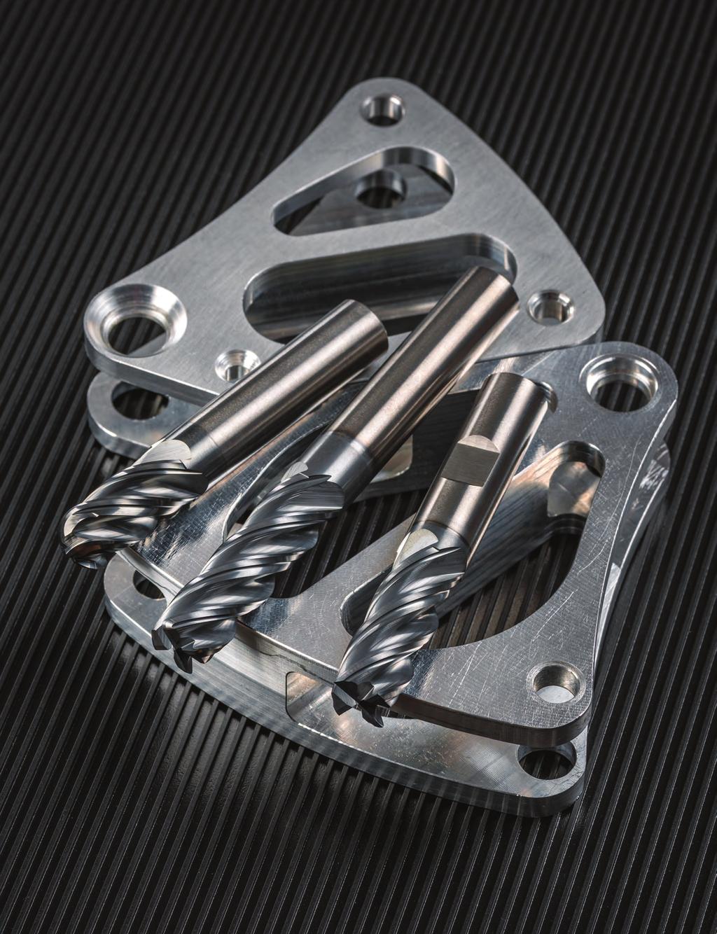
83 83

84 STREAKERS SHEAR IT AND CLEAR IT. IMCO s unique design makes STREAKERS end mills first-rate roughers and excellent finishers. Get high metal removal rates without maxing out horsepower. 84


85 M2 Series Features Features WON T GUM UP THE WORKS. Introducing the new members of the STREAKERS family the M223 and M233 end mills. The M223 STREAKERS end mills keep the best features of our original end mills and add new grinds for better part finishes and ZrN coating for extended tool life. The M233 is a true roughing end mill made to plow through gummy aluminum applications without packing up. The legacy members of the STREAKERS family retain their unique fluting and edge design to efficiently shear through aluminum alloys with great tool life. M223 M223N M233 M203 M203N M202 M202N NUMBER OF FLUTES Z3 Z3 Z3 Z3 Z3 Z2 Z2 SQ SQ CR SQ SQ SQ SQ END TYPES CR CR CR CR BN BN BN HELIX ANGLE COATING ZrN ZrN ZrN NONE NONE NONE NONE SHANK TYPES PLAIN PLAIN PLAIN PLAIN PLAIN PLAIN PLAIN WELDON NECK WELDON NECK WELDON NECK APPLICATIONS ROUGH FINISH ROUGH ROUGH FINISH ROUGH MATERIAL(S) N 85


86 M223 STREAKERS For high-performance machining in aluminum alloys. Improved floor and wall finishes, better ramping ability and longer tool life all part of the new M223 STREAKERS design. The unique grinds curl and evacuate gummy aluminum chips, allowing high feed rates without chip packing. Excellent for roughing and finishing. Z3 SQ CR BN 37 ZrN PLAIN WELDON N in: d1: / d2: / mm: d1: / d2: / Shank by Corner Radius d1 d2 l2 l1 SQ.015 CR.030 CR.060 CR.125 CR BN 1/8 1/8 3/16 3/16 1/4 1/4 5/16 5/16 3/8 3/8 1/2 1/2 5/8 5/8 3/4 3/ /4 1-1/ /8 1-1/ / / / /4 2-1/ / /4 2-1/ /16 2-1/ / / /16 2-1/ / /2 3-1/ /8 2-1/ / / /2 3-1/ / /4 3-1/ / / / / / / / /
87 Shank by Corner Radius d1 d2 l2 l1 SQ 0.3 CR 0.5 CR 1.0 CR 1.5 CR 2.0 CR 3.0 CR BN Shank d1 d2 l2 l1 SQ 3/8 3/8 15/16 2-1/ /2 3-1/ /2 1/2 1-1/2 3-1/ /8 5/8 1-7/ / /4 3/4 2-1/ / / M223 w/weldon l 1 l 2 d2 d1 in: d1: / d2: / R 87
88 M223N STREAKERS For high-performance machining in aluminum alloys. Adding a necked shank to the M223 design offers a highperformance tool that can reach into deep cavities while minimizing tool deflection. Great for work in pockets. Z3 SQ CR BN 37 NECK ZrN PLAIN l 1 l 3 l 2 d2 d1 (optional) R N in: d1: / d2: / mm: d1: / d2: / Shank Reach LBS by Corner Radius d1 d2 l2 l3 l1 SQ.015 CR.030 CR.060 CR.125 CR BN 1/8 1/8 1/4 3/16 3/16 1/4 1/4 1/4 3/8 3/8 3/8 1/2 1/2 1/2 5/8 5/8 5/8 3/4 3/4 3/ /4 3/4 2-1/ /4 2-1/ /8 2-1/ / / /8 2-1/ / / / / / / / / / / / / / / /


89 Shank Reach LBS by Corner Radius d1 d2 l2 l3 l1 SQ 0.3 CR 0.5 CR 1.0 CR 1.5 CR 2.0 CR 3.0 CR BN TOOL TIP Coatings for Tools that Machine Aluminum. IMCO offers two types of coating on end mills designed to machine aluminum and copper alloys: tac (photo A) The ultimate coating for high-output machining in non-ferrous materials. This thin film coating keeps the tool cutting edges sharp for a highshear plane. Very hard with high thermal stability and excellent wear resistance. Find APT/C end mills with tac coating on pages Zirconium Nitride (ZrN) (photo B) Adds hardness and lubricity to the cutting edge. Reduces edge build-up common in machining gummy materials, enhancing tool life and surface finish. All new M223 and M233 end mills are coated with ZrN. A B 89
90 M223 Series Application Guide Speed & Feed (inch) ISO N Work Material Aluminum Alloys 6061, 7075, 2024 High Silicon Aluminum A380, A390 Magnesium Alloys Copper Alloys, Brass Bronze Composites, Plastic, Fiberglass Type of Axial Radial Number Speed Feed (Inch per Tooth) Cut DOC DOC of Flutes (SFM) 1/8 3/16 1/4 3/8 1/2 5/8 3/4 1 Slotting 1 x D 1 x D Peripheral - Rough 2 x D.5 x D Peripheral - Rough > 2-3 x D.5 x D Peripheral - Rough > 3-4 x D.45 x D Peripheral - Rough > 4-5 x D.4 x D Finish 2.5 x D.015 x D *Helical Ramp Angle 3.0 deg. 1 x D Slotting.75 x D 1 x D Peripheral - Rough 2 x D.4 x D Peripheral - Rough > 2-3 x D.4 x D Peripheral - Rough > 3-4 x D.375 x D Peripheral - Rough > 4-5 x D.35 x D Finish 2.5 x D.015 x D *Helical Ramp Angle 2.5 deg. 1 x D Slotting 1 x D 1 x D Peripheral - Rough 2 x D.5 x D Peripheral - Rough > 2-3 x D.5 x D Peripheral - Rough > 3-4 x D.45 x D Peripheral - Rough > 4-5 x D.4 x D Finish 2.5 x D.015 x D *Helical Ramp Angle 3.0 deg. 1 x D Slotting.75 x D 1 x D Peripheral - Rough 2 x D.4 x D Peripheral - Rough > 2-3 x D.4 x D Peripheral - Rough > 3-4 x D.375 x D Peripheral - Rough > 4-5 x D.35 x D Finish 2.5 x D.015 x D *Helical Ramp Angle 2.5 deg. 1 x D Slotting.75 x D 1 x D Peripheral - Rough 2 x D.4 x D Peripheral - Rough > 2-3 x D.4 x D Peripheral - Rough > 3-4 x D.375 x D Peripheral - Rough > 4-5 x D.35 x D Finish 2.5 x D.015 x D *Helical Ramp Angle 2.0 deg. 1 x D Slotting.75 x D 1 x D Peripheral - Rough 2 x D.4 x D Peripheral - Rough > 2-3 x D.4 x D Peripheral - Rough > 3-4 x D.375 x D Peripheral - Rough > 4-5 x D.35 x D Finish 2.5 x D.015 x D *Helical Ramp Angle 3.0 deg. 1 x D *Straight-Line Ramp Angle = Helical Ramp Angle x 5 for entry up to 1 x D. Approximately Equals < > = Less Than or Equal To Greater Than or Equal To Multiply Less Than Greater Than Equals Common Machining Formulas SFM x 3.82 D RPM= SFM = RPM x D x.262 IPM = RPM x IPT x Z MRR = RDOC x ADOC x IPM M/min x D RPM= M/min= RPM x D x MMPM= RPM x MMPT x Z MRR = RDOC x ADOC x MMPM Axial DOC Radial DOC 90
91 M223 Series Application Guide Speed & Feed (metric) ISO N Work Material Aluminum Alloys 6061, 7075, 2024 High Silicon Aluminum A380, A390 Magnesium Alloys Copper Alloys, Brass Bronze Composites, Plastic, Fiberglass Type of Axial Radial Number Speed Feed (MM per Tooth) Cut DOC DOC of Flutes (M/min) Slotting 1 x D 1 x D Peripheral - Rough 2 x D.5 x D Peripheral - Rough > 2-3 x D.5 x D Peripheral - Rough > 3-4 x D.45 x D Peripheral - Rough > 4-5 x D.4 x D Finish 2.5 x D.015 x D *Helical Ramp Angle 3.0 deg. 1 x D Slotting.75 x D 1 x D Peripheral - Rough 2 x D.4 x D Peripheral - Rough > 2-3 x D.4 x D Peripheral - Rough > 3-4 x D.375 x D Peripheral - Rough > 4-5 x D.35 x D Finish 2.5 x D.015 x D *Helical Ramp Angle 2.5 deg. 1 x D Slotting 1 x D 1 x D Peripheral - Rough 2 x D.5 x D Peripheral - Rough > 2-3 x D.5 x D Peripheral - Rough > 3-4 x D.45 x D Peripheral - Rough > 4-5 x D.4 x D Finish 2.5 x D.015 x D *Helical Ramp Angle 3.0 deg. 1 x D Slotting.75 x D 1 x D Peripheral - Rough 2 x D.4 x D Peripheral - Rough > 2-3 x D.4 x D Peripheral - Rough > 3-4 x D.375 x D Peripheral - Rough > 4-5 x D.35 x D Finish 2.5 x D.015 x D *Helical Ramp Angle 2.5 deg. 1 x D Slotting.75 x D 1 x D Peripheral - Rough 2 x D.4 x D Peripheral - Rough > 2-3 x D.4 x D Peripheral - Rough > 3-4 x D.375 x D Peripheral - Rough > 4-5 x D.35 x D Finish 2.5 x D.015 x D *Helical Ramp Angle 2.0 deg. 1 x D Slotting.75 x D 1 x D Peripheral - Rough 2 x D.4 x D Peripheral - Rough > 2-3 x D.4 x D Peripheral - Rough > 3-4 x D.375 x D Peripheral - Rough > 4-5 x D.35 x D Finish 2.5 x D.015 x D *Helical Ramp Angle 3.0 deg. 1 x D *Straight-Line Ramp Angle = Helical Ramp Angle x 5 for entry up to 1 x D. D Z RPM SFM M/min IPM MMPM IPT MMPT MRR RDOC ADOC Tool meter Number of Flutes Revolutions per Minute Surface Feet per Minute Surface Meters per Minute Inches per Minute Millimeters per Minute Inch per Tooth Millimeters per Tooth Metal Removal Rate Radial Depth Axial Depth Technical Resources Information on tips and adjustments for the following milling operations can be found in our Technical Resources section beginning on page 125. HEM slotting Face milling Helical entry ramping Straight line ramping Long tool projection adjustments Ball nose milling adjustments Other helpful tips and calculations 91
92 M233 ROUGHER STREAKERS Z3 CR 37 ZrN PLAIN For high-performance machining in aluminum alloys. Special cutting edge serrations reduce the horsepower needed to plow through aluminum alloys at high metal removal rates. The ZrN coating helps reduce chip packing even in heavy tool engagement cuts. d2 l 1 l 2 d 1 R Tool Tip: M233 Rougher end mills show up to 20% power reduction from M223 in the same cut. N in: d1: / d2: / mm: d1: / d2: / Shank by Corner Radius d1 d2 l2 l1.015 CR.030 CR 1/4 1/4 3/8 3/8 1/2 1/2 5/8 5/8 3/4 3/ /4 2-1/ /16 2-1/ / /2 3-1/ / /2 3-1/ /4 3-1/ / / / / Shank by Corner Radius d1 d2 l2 l1 0.5 CR 1.0 CR
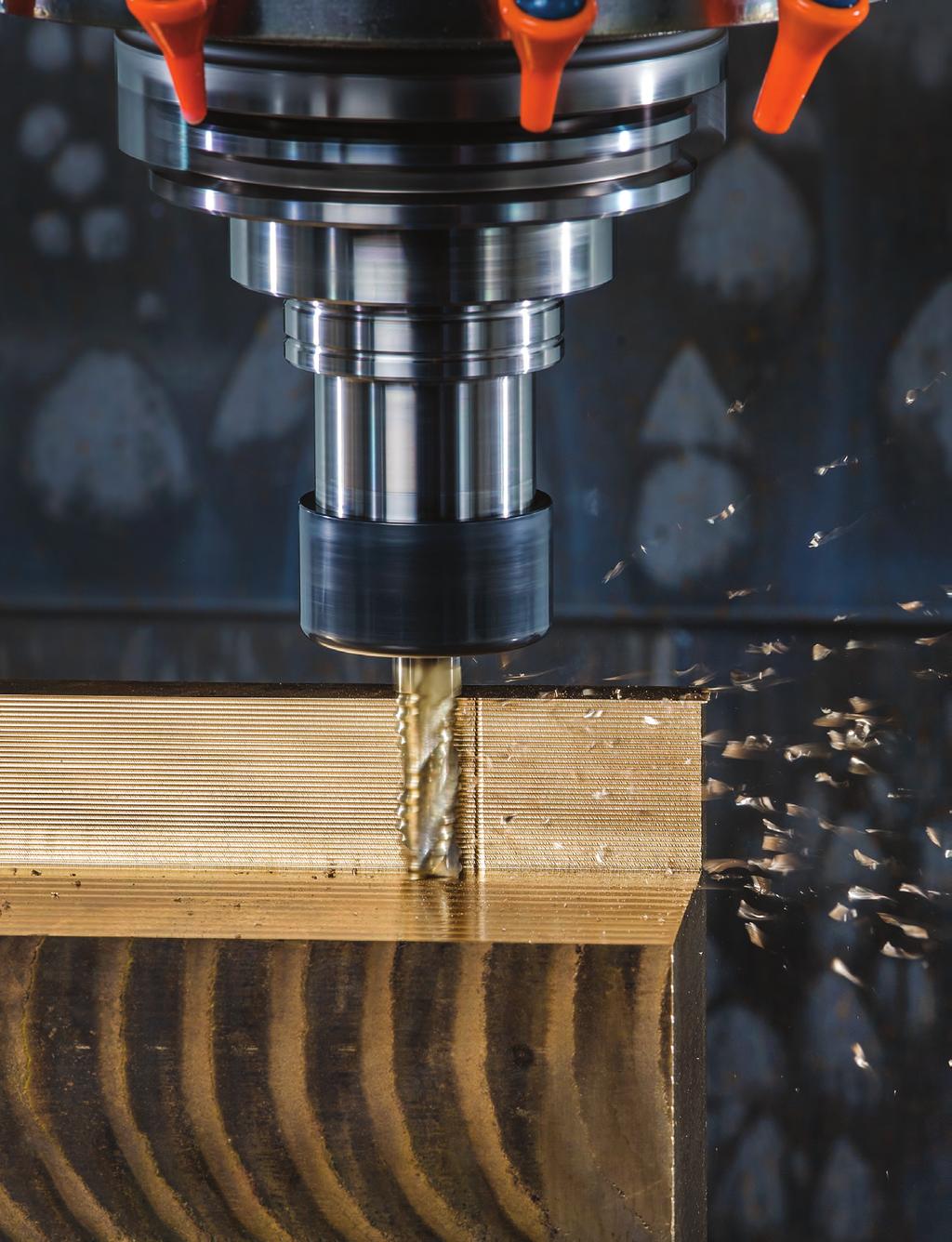
93 93
94 M233 Series Application Guide Speed & Feed (inch) ISO Type of Axial Radial Number Speed Feed (Inches per Tooth) Work Material Cut DOC DOC of Flutes (SFM) 1/4 3/8 1/2 5/8 3/4 1 Slotting 1 x D 1 x D Peripheral - Rough 2 x D.5 x D Aluminum Alloys Peripheral - Rough > 2-3 x D.5 x D , 6061, 7075 Peripheral - Rough > 3-4 x D.45 x D *Helical Ramp Angle 3.0 deg. 1 x D Slotting.75 x D 1 x D High Silicon Peripheral - Rough 2 x D.4 x D Aluminum Peripheral - Rough > 2-3 x D.4 x D A380, A390 Peripheral - Rough > 3-4 x D.375 x D *Helical Ramp Angle 2.5 deg. 1 x D Slotting 1 x D 1 x D Peripheral - Rough 2 x D.5 x D Magnesium Alloys Peripheral - Rough > 2-3 x D.5 x D Peripheral - Rough > 3-4 x D.45 x D *Helical Ramp Angle 3.0 deg. 1 x D N Slotting.75 x D 1 x D Peripheral - Rough 2 x D.4 x D Copper Alloys, Peripheral - Rough > 2-3 x D.4 x D Brass Peripheral - Rough > 3-4 x D.375 x D *Helical Ramp Angle 2.5 deg. 1 x D Slotting.75 x D 1 x D Peripheral - Rough 2 x D.4 x D Bronze Peripheral - Rough > 2-3 x D.4 x D Peripheral - Rough > 3-4 x D.375 x D *Helical Ramp Angle 2.0 deg. 1 x D Slotting.75 x D 1 x D Composites, Peripheral - Rough 2 x D.4 x D Plastics, Peripheral - Rough > 2-3 x D.4 x D Fiberglass Peripheral - Rough > 3-4 x D.375 x D *Helical Ramp Angle 3.0 deg. 1 x D *Straight-Line Ramp Angle = Helical ramp angle x 5 for entry up to 1 x D. Approximately Equals < Less Than Tool Tip: M233 Rougher end mills show up to 20% power reduction from M223 in the same cut. Less Than or Equal To > Greater Than Greater Than or Equal To Multiply = Equals Common Machining Formulas SFM x 3.82 D RPM= SFM = RPM x D x.262 IPM = RPM x IPT x Z MRR = RDOC x ADOC x IPM M/min x D RPM= M/min= RPM x D x MMPM= RPM x MMPT x Z MRR = RDOC x ADOC x MMPM Axial DOC Radial DOC 94
95 M233 Series Application Guide Speed & Feed (metric) ISO Type of Axial Radial Number Speed Feed (MM per Tooth) Work Material Cut DOC DOC of Flutes (M/min) Slotting 1 x D 1 x D Peripheral - Rough 2 x D.5 x D Aluminum Alloys Peripheral - Rough > 2-3 x D.5 x D , 6061, 7075 Peripheral - Rough > 3-4 x D.45 x D *Helical Ramp Angle 3.0 deg. 1 x D Slotting.75 x D 1 x D High Silicon Peripheral - Rough 2 x D.4 x D Aluminum Peripheral - Rough > 2-3 x D.4 x D A380, A390 Peripheral - Rough > 3-4 x D.375 x D *Helical Ramp Angle 2.5 deg. 1 x D Slotting 1 x D 1 x D Peripheral - Rough 2 x D.5 x D Magnesium Alloys Peripheral - Rough > 2-3 x D.5 x D Peripheral - Rough > 3-4 x D.45 x D *Helical Ramp Angle 3.0 deg. 1 x D N Slotting.75 x D 1 x D Peripheral - Rough 2 x D.4 x D Copper Alloys, Peripheral - Rough > 2-3 x D.4 x D Brass Peripheral - Rough > 3-4 x D.375 x D *Helical Ramp Angle 2.5 deg. 1 x D Slotting.75 x D 1 x D Peripheral - Rough 2 x D.4 x D Bronze Peripheral - Rough > 2-3 x D.4 x D Peripheral - Rough > 3-4 x D.375 x D *Helical Ramp Angle 2.0 deg. 1 x D Slotting.75 x D 1 x D Composites, Peripheral - Rough 2 x D.4 x D Plastics, Peripheral - Rough > 2-3 x D.4 x D Fiberglass Peripheral - Rough > 3-4 x D.375 x D *Helical Ramp Angle 3.0 deg. 1 x D *Straight-Line Ramp Angle = Helical ramp angle x 5 for entry up to 1 x D. Tool Tip: M233 Rougher end mills show up to 20% power reduction from M223 in the same cut. D Z RPM SFM M/min IPM MMPM IPT MMPT MRR RDOC ADOC Tool meter Number of Flutes Revolutions per Minute Surface Feet per Minute Surface Meters per Minute Inches per Minute Millimeters per Minute Inch per Tooth Millimeters per Tooth Metal Removal Rate Radial Depth Axial Depth Technical Resources Information on tips and adjustments for the following milling operations can be found in our Technical Resources section beginning on page 125. HEM slotting Face milling Helical entry ramping Straight line ramping Long tool projection adjustments Ball nose milling adjustments Other helpful tips and calculations 95
96 M203 STREAKERS For high-performance machining in aluminum alloys. Unique grinds curl and evacuate gummy aluminum chips, allowing high feed rates without clogging. Excellent tool life. The 3-flute design yields a superior finish. N Z3 d2 SQ CR 45 NONE PLAIN l1 in: d1: / d2: / mm: d1: / d2: / l2 d1 R Shank by Corner Radius d1 d2 l2 l1 SQ.015 CR.030 CR.060 CR.125 CR 1/8 1/8 3/16 3/16 1/4 1/4 5/16 5/16 3/8 3/8 1/2 1/2 5/8 5/8 3/4 3/ /4 1-1/ /8 1-1/ / / /8 2-1/ /4 2-1/ / /16 2-1/ / /2 2-1/ / /2 3-1/ / / / / /8 3-1/ / / / / / / / / Shank d1 d2 l2 l1 SQ
97 M203 w/weldon STREAKERS Z3 SQ 45 NECK NONE WELDON For high-performance machining in aluminum alloys. Unique grinds curl and evacuate gummy aluminum chips, allowing high feed rates without clogging. Excellent tool life. The 3-flute design yields a superior finish. d2 l 1 l 2 d 1 (optional) R in: d1: / d2: / Shank d1 d2 l2 l1 SQ 1/4 1/4 3/8 3/8 1/2 1/2 5/8 5/8 3/4 3/ /4 2-1/ / /8 2-1/ /2 3-1/ /4 3-1/ /4 3-1/ / / / / / / Shank Reach LBS d1 d2 l2 l3 l1 SQ 1/4 1/4 3/8 3/8 3/8 1/2 1/2 1/2 5/8 5/8 5/8 3/4 3/4 3/ /8 2-1/ / / /8 2-1/ / / / / / / /2 3-1/ / / / / / M203N d 2 l 1 LBS in: d1: / d2: / For high-performance machining in aluminum alloys. Adding a necked shank to the M203 design offers a high-performance tool that permits clearance in deeper cavities and easier machining against tight walls. Neck relief and short flute length combine to increase end mill stability in the cut for more precise tolerances. Great for work in pockets. l 2 d 1 R 97
98 M202 STREAKERS For high-performance machining in aluminum alloys. Unique grinds curl and evacuate gummy aluminum chips, allowing high feed rates without clogging. The 2-flute design increases the chip evacuation area, allowing more tool engagement. Excellent tool life. Z2 SQ CR BN 45 NONE PLAIN d 2 l 1 l 2 d 1 R N in: d1: / d2: / mm: d1: / d2: / Shank by Corner Radius d1 d2 l2 l1 SQ.015 CR.030 CR.060 CR.125 CR BN 1/8 1/8 3/16 3/16 1/4 1/4 5/16 5/16 3/8 3/8 1/2 1/2 5/8 5/8 3/4 3/4 1/4 1-1/ /8 1-1/ / / /8 2-1/ /4 2-1/ / /16 2-1/ / /2 2-1/ / /2 3-1/ / / / /8 3-1/ / / / / / Shank d1 d2 l2 l1 SQ BN
99 M202 w/weldon STREAKERS For high-performance machining in aluminum alloys. Unique grinds curl and evacuate gummy aluminum chips, allowing high feed rates without clogging. The 2-flute design increases the chip evacuation area, allowing more tool engagement. Excellent tool life. Z2 SQ CR BN 45 NECK NONE WELDON d2 l 1 l2 d 1 (optional) R N in: d1: / d2: / Shank by Corner Radius d1 d2 l2 l1 SQ.015 CR.030 CR.060 CR BN 1/4 1/4 5/16 5/16 3/8 3/8 1/2 1/2 5/8 5/8 3/4 3/4 3/4 2-1/ / /16 2-1/ / /8 2-1/ /2 3-1/ /4 3-1/ / /4 3-1/ / / / / Shank Reach LBS d1 d2 l2 l3 l1 SQ 1/4 1/4 3/8 3/8 3/8 1/2 1/2 1/2 5/8 5/8 5/8 3/4 3/4 3/ /8 2-1/ / / /8 2-1/ / / / / / / /2 3-1/ / / / / / M202N in: d1: / d2: / l 1 LBS d 2 d 1 For high-performance machining in aluminum alloys. Adding a necked shank to the M202 design offers a high-performance tool that permits clearance in deeper cavities and easier machining against tight walls. Neck relief and short flute length combine to increase end mill stability in the cut for more precise tolerances. Great for work in pockets. l 2 R 99
100 M2 Series Application Guide Speed & Feed (inch) ISO N D = Tool meter Work Material Aluminum Alloys 2024, 6061, 7075 High Silicon Aluminum A380, A390 Magnesium Alloys Copper Alloys Brass, Bronze Composites Plastics, Fiberglass Aluminum Alloys 2024, 6061, 7075 High Silicon Aluminum A380, A390 Magnesium Alloys Copper Alloys Brass, Bronze Composites Plastics, Fiberglass Type of Axial Radial Number Speed Feed (Inch per Tooth) Cut DOC DOC of Flutes (SFM) 1/8 3/16 1/4 5/16 3/8 1/2 5/8 3/4 1 Slotting 1 x D 1 x D Peripheral - Rough 1 x D.75 x D Peripheral - Finish 1.5 x D.01 x D Slotting.75 x D 1 x D Peripheral - Rough 1 x D.5 x D Peripheral - Finish 1.5 x D.01 x D Slotting 1 x D 1 x D Peripheral - Rough 1 x D.75 x D Peripheral - Finish 1.5 x D.01 x D Slotting.75 x D 1 x D Peripheral - Rough 1 x D.75 x D Peripheral - Finish 1.5 x D.01 x D Slotting 1 x D 1 x D Peripheral - Rough 1 x D.75 x D Peripheral - Finish 1.5 x D.01 x D Slotting.75 x D 1 x D Peripheral - Rough 1 x D.75 x D Peripheral - Finish 1.5 x D.01 x D Slotting.5 x D 1 x D Peripheral - Rough 1 x D.5 x D Peripheral - Finish 1.5 x D.01 x D Slotting.75 x D 1 x D Peripheral - Rough 1 x D.75 x D Peripheral - Finish 1.5 x D.01 x D Slotting.75 x D 1 x D Peripheral - Rough 1 x D.75 x D Peripheral - Finish 1.5 x D.01 x D Slotting 1 x D 1 x D Peripheral - Rough 1 x D.75 x D Peripheral - Finish 1.5 x D.01 x D Approximately Equals Less Than or Equal To Greater Than or Equal To Multiply < > = Less Than Greater Than Equals Common Machining Formulas SFM x 3.82 D RPM= SFM = RPM x D x.262 IPM = RPM x IPT x Z MRR = RDOC x ADOC x IPM M/min x D RPM= M/min= RPM x D x MMPM= RPM x MMPT x Z MRR = RDOC x ADOC x MMPM Axial DOC Radial DOC 100
101 M2 Series Application Guide Speed & Feed (metric) ISO N Work Material Aluminum Alloys 2024, 6061, 7075 High Silicon Aluminum A380, A390 Magnesium Alloys Copper Alloys Brass, Bronze Composites Plastics, Fiberglass Aluminum Alloys 2024, 6061, 7075 High Silicon Aluminum A380, A390 Magnesium Alloys Copper Alloys Brass, Bronze Composites Plastics, Fiberglass Type of Cut Axial DOC Radial DOC Number of Flutes Speed (M/Min) Feed (MM per Tooth) Slotting 1 x D 1 x D Peripheral - Rough 1 x D.75 x D Peripheral - Finish 1.5 x D.01 x D Slotting.75 x D 1 x D Peripheral - Rough 1 x D.5 x D Peripheral - Finish 1.5 x D.01 x D Slotting 1 x D 1 x D Peripheral - Rough 1 x D.75 x D Peripheral - Finish 1.5 x D.01 x D Slotting.75 x D 1 x D Peripheral - Rough 1 x D.75 x D Peripheral - Finish 1.5 x D.01 x D Slotting 1 x D 1 x D Peripheral - Rough 1 x D.75 x D Peripheral - Finish 1.5 x D.01 x D Slotting.75 x D 1 x D Peripheral - Rough 1 x D.75 x D Peripheral - Finish 1.5 x D.01 x D Slotting.5 x D 1 x D Peripheral - Rough 1 x D.5 x D Peripheral - Finish 1.5 x D.01 x D Slotting.75 x D 1 x D Peripheral - Rough 1 x D.75 x D Peripheral - Finish 1.5 x D.01 x D Slotting.75 x D 1 x D Peripheral - Rough 1 x D.75 x D Peripheral - Finish 1.5 x D.01 x D Slotting 1 x D 1 x D Peripheral - Rough 1 x D.75 x D Peripheral - Finish 1.5 x D.01 x D D = Tool meter D Z RPM SFM M/min IPM MMPM IPT MMPT MRR RDOC ADOC Tool meter Number of Flutes Revolutions per Minute Surface Feet per Minute Surface Meters per Minute Inches per Minute Millimeters per Minute Inch per Tooth Millimeters per Tooth Metal Removal Rate Radial Depth Axial Depth Technical Resources Information on tips and adjustments for the following milling operations can be found in our Technical Resources section beginning on page 125. HEM slotting Face milling Helical entry ramping Straight line ramping Long tool projection adjustments Ball nose milling adjustments Other helpful tips and calculations 101


102 trucore GENERAL PURPOSE DOES NOT MEAN SECOND CLASS. IMCO s trucore series of end mills are all made from high-grade substrate and are ground to strict standards making our base tools outstanding in their class. 102


103 trucore Features BETTER PRECISION, LONGER TOOL LIFE BY DESIGN. Optimized flute designs and a high-strength core give our trucore E series end mills cutting performance you do not see with conventional general-purpose tools. TruCORE end mills are CNC ground from the highest quality material, maximizing performance and repeatability. E14 E14 E14 E14 E24 E13 E13 E12 M104 E520B NUMBER OF FLUTES Z4 Z4 Z4 Z4 Z4 Z3 Z3 Z2 Z4 Z2 SQ SQ SQ SQ SQ SQ SQ SQ SQ BN END TYPES CR BN BN BN BN BN BN HELIX ANGLE COATING ALTIN TICN TiN NONE ALTiN ALTiN NONE ALTiN ALTIN ALTiN NONE SHANK TYPES PLAIN PLAIN PLAIN PLAIN PLAIN PLAIN PLAIN PLAIN PLAIN PLAIN WELDON WELDON WELDON NECK ROUGH APPLICATIONS ROUGH FINISH ROUGH ROUGH FINISH MATERIAL(S) K P M S N P M H 103
104 E14 AlTiN trucore Z4 SQ CR BN 30 AlTiN PLAIN WELDON For general machining in a wide range of materials. The E14 offers the most cutting edges in a general-purpose tool design. Best for roughing and finishing in a broad range of machining environments. The AlTiN coating offers superior heat resistance and hardness for increased tool life. d2 l 1 l 2 d 1 (optional) R K P M S in: d1: / d2: / Shank by Corner Radius d1 d2 l2 l1 SQ.015 CR.030 CR.060 CR.090 CR.120 CR BN 1/32 1/8 3/32 1-1/ /64 1/8 9/64 1-1/ /8 1-1/ /16 1/8 3/16 1-1/ /4 1-1/ /64 1/8 1/4 1-1/ /32 1/8 3/16 1-1/ /8 1-1/ /64 1/8 3/8 1-1/ /4 1-1/ /2 1-1/ /8 1/8 5/ /4 2-1/ /64 3/16 9/ /32 3/16 5/ / /64 3/16 5/ / / /16 3/16 3/4 2-1/ / /64 1/4 5/8 2-1/ /32 1/4 5/8 2-1/ /64 1/4 3/4 2-1/ / /4 2-1/ /4 1/ / / / /64 5/16 3/4 2-1/ /32 5/16 3/4 2-1/ /64 5/16 13/16 2-1/ / /16 5/16 13/16 2-1/ / / /64 3/ / /32 3/ / /64 3/ / / / /8 3/8 1-1/ / /
105 Shank by Corner Radius d1 d2 l2 l1 SQ.015 CR.030 CR.060 CR.090 CR.120 CR BN 25/64 7/ / /32 7/ / /64 7/ / /16 7/ / /64 1/ /32 1/ /64 1/ /8 2-1/ /2 1/2 1-1/ /16 9/16 1-1/4 3-1/ /4 3-1/ /8 5/8 2-1/ /16 3/4 1-1/ / /4 3/4 2-1/ /16 7/8 1-1/ /8 7/8 1-1/ / / / / Shank Shank d1 d2 d2 l2 l2 l1 l1 SQ SQ 3/8 3/8 1/2 1/2 5/8 5/8 3/4 3/ / / /4 3-1/ / / / / / E14 w/weldon l 1 l 2 d2 d1 in: d1: / d2: /
106 E14 AlTiN trucore Z4 SQ BN 30 AlTiN PLAIN For general machining in a wide range of materials. The E14 offers the most cutting edges in a general-purpose tool l 1 l 2 design. Best for roughing and finishing in a broad range of machining environments. The AlTiN coating offers superior d2 d 1 heat resistance and hardness for increased tool life. K P M S mm: d1: / d2: / Shank d1 d2 l2 l1 SQ BN , , ,

107 E14 TiCN trucore Z4 SQ BN 30 TiCN PLAIN WELDON For general machining in a wide range of materials. The E14 l 1 l 2 offers the most cutting edges in a general-purpose tool design. Best for roughing and finishing in a broad range of machining environments. The TiCN coating protects the cutting edge and increases tool life over uncoated end mills. d2 d 1 K P M S in: d1: / d2: / Shank d1 d2 l2 l1 SQ BN 1/32 1/8 3/32 1-1/ /64 1/8 9/64 1-1/ /16 1/8 3/16 1-1/ /32 1/8 3/8 1-1/ /4 1-1/ /8 1/8 1/2 1-1/ /4 2-1/ /32 3/16 9/ / /16 3/16 5/ / / /4 1/4 3/4 2-1/ / / /16 5/16 13/16 2-1/ / /8 3/8 1-1/ / /16 7/ / /2 1/ /4 3-1/ /8 5/8 2-1/ / /4 3/4 2-1/ / / Shank d1 d2 l2 l1 SQ 3/8 3/ / /2 1/ /8 5/8 1-1/4 3-1/ /4 3/4 1-1/ E14 w/weldon d2 l 1 l 2 d1 in: d1: / d2: /
108 E14 UNCOATED trucore Z4 SQ BN 30 NONE PLAIN WELDON For general machining in a wide range of materials. The l 1 l 2 E14 offers the most cutting edges in a general-purpose tool design. Best for roughing and finishing in a broad d2 d1 range of machining environments. K P M S in: d1: / d2: / mm: d1: / d2: / Shank d1 d2 l2 l1 SQ BN 1/32 1/8 3/32 1-1/ /64 1/8 9/64 1-1/ /16 1/8 3/16 1-1/ /64 1/8 1/4 1-1/ /32 1/8 3/8 1-1/ /64 1/8 3/8 1-1/ /4 1-1/ /8 1/8 1/2 1-1/ /4 2-1/ /32 3/16 9/ / /16 3/16 5/ /4 2-1/ / /32 1/4 5/8 2-1/ / /4 1/4 3/4 2-1/ / / /16 2-1/ /16 5/16 1-1/ / / /8 3/ / / / /16 7/ / /8 2-1/ /2 1/ /4 3-1/ /8 5/8 2-1/ / /4 3/4 2-1/ / /
109 Shank d1 d2 l2 l1 SQ , , Shank d1 d2 l2 l1 SQ 3/8 3/ / /2 1/ /8 5/8 1-1/4 3-1/ /4 3/4 1-1/ E14 w/weldon d2 l 1 l 2 d1 in: d1: / d2: /
110 E14 TiN trucore For general machining in a wide range of materials. The E14 offers the most cutting edges in a general tool design. Best for roughing and finishing in a broad range of machining environments. The TiN coating protects the cutting edge and increases tool life over uncoated end mills. K P M S N d2 Z4 SQ 30 TiN PLAIN l 1 l 2 in: d1: / d2: / d 1 Shank d1 d2 l2 l1 SQ 1/16 1/8 3/16 1-1/ /32 1/8 3/8 1-1/ /8 1/8 1/2 1-1/ /16 3/16 5/ /4 1/4 3/4 2-1/ /16 5/16 13/16 2-1/ /8 3/ / /2 1/ /8 5/8 1-1/4 3-1/ /4 3/4 1-1/ TOOL TIP Driving Performance to the Edge. What makes IMCO end mills the best choice for your everyday applications? Strength: All IMCO trucore end mills are made using submicron grain carbide with a 10% cobalt binder, increasing the transverse rupture strength for longer durability and even edge wear. Consistency: IMCO end mills are manufactured on high-precision CNC grinders to exacting standards, ensuring repeatability from tool to tool. Variety: Many length and dimension options are available in tools with 2-, 3- or 4-flutes many with highperformance coatings. Weldon flats are available on common sizes. With all of this, it s easy to see how IMCO tooling can give you maximum performance when working in a wide range of materials. 110


111 E24 AlTiN trucore Z4 SQ BN 30 ALTiN PLAIN For general machining in a wide range of materials. The E24 offers the reliability of our general-purpose tool design in a double- l 1 l 2 ended form. Best for roughing and finishing in a broad range of machining environments. The AlTiN coating offers superior heat d2 d 1 resistance and hardness for increased tool life. K P M S in: d1: / d2: / Shank d1 d2 l2 l1 SQ BN 1/32 1/8 1/16 1-1/ /64 1/8 3/32 1-1/ /16 1/8 1/8 1-1/ /64 1/8 1/8 1-1/ /32 1/8 3/16 1-1/ /64 1/8 3/16 1-1/ /8 1/8 1/4 1-1/ /64 3/16 5/ /32 3/16 5/ /64 3/16 5/ /16 3/16 3/ /32 1/4 1/2 2-1/ /4 1/4 1/2 2-1/ /16 5/16 1/2 2-1/ /8 3/8 9/16 2-1/ /2 1/2 5/


112 E13 AlTiN trucore 30 For general machining in a wide range of materials. The E13 offers a combination of strong cutting edges with increased flute spacing in a general-purpose tool design. Best for roughing and finishing in slots and pockets and in gummy materials. The AlTiN coating offers superior heat resistance and hardness for increased tool life. Shank d1 d2 l2 l1 SQ BN 1/32 1/8 3/32 1-1/ /64 1/8 9/64 1-1/ /16 1/8 1/8 1-1/ /16 1-1/ /32 1/8 3/16 1-1/ /8 1-1/ /4 1-1/ /8 1/8 1/2 1-1/ /4 2-1/ /32 3/16 9/ / /16 3/16 5/ /4 2-1/ / / /4 1/4 3/4 2-1/ / / /16 5/16 13/16 2-1/ /8 3/ / / /2 1/ /8 5/8 1-1/4 3-1/ /4 3/4 1-1/ / Z3 d2 SQ BN AlTiN PLAIN l 1 l 2 in: d1: / d2: / mm: d1: / d2: / P M N d TOOL TIP Aim For a Chip-Free Cutting Zone. The proper location and volume of flood coolant are essential for a successful cut. Coolant plays a very important part in chip evacuation, especially when machining in a pocket or closed area. But simply blasting a large amount of coolant at the end mill isn t the most effective way to flush chips from the cutting zone. In fact, failure to direct the coolant properly increases the risk of re-cutting chips, causing tool damage and premature wear. As this series of photos demonstrates, the most productive way to flush chips out of a pocket is to direct the coolant to the bottom of the cut. This allows the coolant to rebound off the tool and part floor, lifting the chips out and away from the tool s cutting edges Poor Poor Coolant flow is perpendicular to the end mill, flowing past the end mill without hitting it directly. This will not evacuate the chips from the flutes sufficiently or provide proper cooling to the cutting edges. Coolant flow is hitting the end mill nicely, but it is perpendicular to it. This will cool the end mill but will not lift and flush the chips out of the cutting zone.


113 Shank d1 d2 l2 l1 SQ BN , , , Poor Coolant volume is weak and too high. The coolant is not aimed into the cutting zone, which limits its effectiveness in flushing the chips, lubricating and cooling at the point of cut. Good This example of coolant placement shows plenty of flush at the end mill. The three spray nozzles are pointing down at the end mill, forcing the chips up and out of the cutting zone. Poor There is not enough coolant volume to adequately flush chips out of the cutting zone. This condition will result in re-cutting of chips and premature tool wear. Best The best coolant flush for evacuating chips from a pocket uses a coolant flush-type collet and through-spindle coolant (if your machine is equipped with it). Coolant is forced all around the end mill 360 at high pressure. High-pressure coolant hits the bottom of the cut and lifts the chips out and away from the cutting zone quickly and efficiently. 113
114 E13 UNCOATED trucore Z3 SQ 30 NONE PLAIN For general machining in a wide range of materials. The E13 offers a combination of strong cutting edges with increased flute spacing in l 1 l 2 a general-purpose tool design. Best for roughing and finishing in slots and pockets and in gummy materials. d2 d 1 P M N in: d1: / d2: / Shank d1 d2 l2 l1 SQ 1/4 1-1/ /8 1/8 1/2 1-1/ /4 2-1/ / /16 3/16 5/ /4 2-1/ / / /4 1/4 3/4 2-1/ / /16 5/16 13/16 2-1/ /8 3/ / / /2 1/ /8 5/8 1-1/4 3-1/ /4 3/4 1-1/ / TOOL TIP Tool Modifications. Special tooling requirements can often be met through one or more of these simple modifications of standard, off-the-shelf products. Add corner radius or chamfer (Note that corners on some series cannot be modified) Add a Weldon flat to tool shank Add a neck relief Shorten flute length Add a drill point to an end mill These coatings can also be added to existing uncoated products. AlTiNX AlTiN AlCrNX TiCN TiN ZrN tac DLC (mond-like Coating) 114

115 115

116 E12 AlTiN trucore Z2 SQ BN 30 AlTiN PLAIN For general machining in a wide range of materials. The E12 offers the maximum flute spacing in a general-purpose tool design. Best for roughing, slotting and pocketing in materials and in applications in which chip evacuation is a challenge. The AlTiN coating offers superior heat resistance and hardness for increased tool life. d2 l 1 l 2 d 1 P M N in: d1: / d2: / mm: d1: / d2: / Shank d1 d2 l2 l1 SQ BN 1/32 1/8 1/16 1-1/ /32 1-1/ /64 1/8 3/32 1-1/ /64 1-1/ /16 1/8 1/8 1-1/ /16 1-1/ /64 1/8 1/4 1-1/ /32 1/8 3/16 1-1/ /8 1-1/ /64 1/8 3/8 1-1/ /4 1-1/ /8 1/8 1/2 1-1/ /4 2-1/ /64 3/16 9/ /32 3/16 9/ /64 3/16 5/ / /16 3/16 5/ /4 2-1/ / /64 1/4 5/8 2-1/ /32 1/4 5/8 2-1/ /64 1/4 3/4 2-1/ /4 1/4 5/16 5/16 3/8 3/8 1/2 1/2 5/8 5/8 3/4 3/4 1/ /4 2-1/ / / /16 2-1/ / / / / / /4 3-1/ / / /

117 Shank d1 d2 l2 l1 SQ BN , , , TOOL RENEWAL SERVICES Resharpen. Restore. Recharge. Get the most out of your tooling investment by utilizing IMCO s reconditioning services. Reconditioning is a cost-effective way to increase the life span and value of your IMCO end mills. No quantity limit 2- to 3-week turnaround upon order confirmation (coating included) on most tools Original coating put back on all IMCO end mills Contact us with questions or for a quote for our resharpening services at regrinds@imcousa.com. You can also find our order form on our website at imcousa.com/resources/catalog. 117
118 E12 UNCOATED trucore Z2 SQ BN 30 NONE PLAIN For general machining in a wide range of materials. The E12 offers the maximum flute spacing in a general- l 1 l 2 purpose tool design. Best for roughing, slotting, and pocketing in materials and in applications in which d2 d 1 chip evacuation is a challenge. P M N in: d1: / d2: / mm: d1: / d2: / Shank d1 d2 l2 l1 SQ BN 1/32 1/8 3/32 1-1/ /64 1/8 9/64 1-1/ /16 1/8 3/16 1-1/ /64 1/8 1/4 1-1/ /32 1/8 3/8 1-1/ /64 1/8 3/8 1-1/ /4 1-1/ /8 1/8 1/2 1-1/ /4 2-1/ /32 3/16 9/ / /16 3/16 5/ /4 2-1/ / / /4 2-1/ /4 1/4 1-1/ / / / /16 5/16 13/16 2-1/ / / / /8 3/8 1-1/ / / /2 1/2 1-1/ /8 5/8 1-1/4 3-1/ / /4 3/4 1-1/ /

119 Shank d1 d2 l2 l1 SQ BN , TOOL TIP Tip for Small-meter End Mills. When using small-diameter end mills, it is not uncommon to have less spindle speed on a machine than what is suggested in the speed and feed chart. When dealing with this condition, it is important to remember to maintain the suggested load on the tool don t decrease the chip load shown in the chart to equal the lower spindle speed. Run the maximum RPM that the machine will safely allow. Use the suggested chip load from the speed and feed chart. Maintain the suggested axial and radial tool engagements. This combination will ensure the best tool life and proper finish. 119
120 E Series Application Guide Speed & Feed (inch) 120 ISO K Work Material Cast Iron - Gray Cast Iron - Ductile Type of Cut Axial DOC Radial DOC Number of Flutes Speed (SFM) Feed (Inches Per Tooth) Uncoated TiCN AlTiN 1/16 1/8 3/16 1/4 5/16 3/8 1/2 5/8 3/4 1 Slotting.5 x D 1 x D Peripheral - Rough 1 x D.5 x D Peripheral - Finish 1.5 x D.01 x D Slotting.5 x D 1 x D Peripheral - Rough 1 x D.5 x D Peripheral - Finish 1.5 x D.01 x D Slotting.5 x D 1 x D Slotting.5 x D 1 x D Low Carbon Steels 1018, 12L14, 8620 Peripheral - Rough 1 x D.5 x D Peripheral - Rough 1 x D.5 x D Finish 1.5 x D.01 x D Slotting.5 x D 1 x D Medium Carbon Steels 4140, 4340 Peripheral - Rough 1 x D.5 x D Finish 1.5 x D.01 x D Slotting.5 x D 1 x D Tool & Die Steels 48 HRC A2, D2, H13, P20 Peripheral - Rough 1 x D.5 x D Finish 1.5 x D.01 x D Slotting.25 x D 1 x D Hardened Steels 49 HRC to 58 HRC Peripheral - Rough 1 x D.25 x D Finish 1.5 x D.01 x D Slotting.5 x D 1 x D Martensitic Stainless Steels 416, 410, 440C Peripheral - Rough 1 x D.5 x D Finish 1.5 x D.01 x D Slotting.5 x D 1 x D Slotting.5 x D 1 x D Austenitic Stainless Steels 303, 304, 316 Peripheral - Rough 1 x D.5 x D Peripheral - Rough 1 x D.5 x D Finish 1.5 x D.01 x D Precipition Hardening Slotting.25 x D 1 x D Stainless Steels Peripheral - Rough 1 x D.25 x D PH, 15-5 PH Finish 1.5 x D.01 x D Slotting.25 x D 1 x D Titanium Alloys Peripheral - Rough 1 x D.25 x D Finish 1.5 x D.01 x D High Temperature Alloys Slotting.25 x D 1 x D Inconel, Haynes, Stellite, Peripheral - Rough 1 x D.25 x D Hastalloy Finish 1.5 x D.01 x D Slotting.5 x D 1 x D Aluminum Alloys 2024, 6061, 7075 Peripheral - Rough 1 x D.5 x D Peripheral - Finish 1.5 x D.01 x D Slotting.5 x D 1 x D Peripheral - Rough 1 x D.5 x D Copper Alloys Brass & Bronze Peripheral - Rough 1 x D.5 x D Peripheral - Finish 1.5 x D.01 x D Peripheral - Finish 1.5 x D.01 x D Slotting.5 x D 1 x D Composites, Plastics Peripheral - Rough 1 x D.5 x D Peripheral - Finish 1.5 x D.01 x D Slotting.5 x D 1 x D Magnesium Alloys Peripheral - Rough 1 x D.5 x D Peripheral - Finish 1.5 x D.01 x D Slotting.5 x D 1 x D Graphite Peripheral - Rough 1 x D.5 x D Peripheral - Finish 1.5 x D.01 x D D = Tool meter Information on tips and adjustments can be found in our Technical Resources section beginning on page 125. P H M S N
121 E Series Application Guide Speed & Feed (metric) ISO K P H M S N D = Tool meter Work Material Cast Iron - Gray Cast Iron - Ductile Low Carbon Steels 1018, 12L14, 8620 Medium Carbon Steels 4140, 4340 Tool & Die Steels 48 HRC A2, D2, H13, P20 Hardened Steels 49 HRC to 58 HRC Martensitic Stainless Steels 416, 410, 440C Austenitic Stainless Steels 303, 304, 316 Precipition Hardening Stainless Steels 17-4 PH, 15-5 PH Titanium Alloys High Temperature Alloys Inconel, Haynes, Stellite, Hastalloy Aluminum Alloys 2024, 6061, 7075 Copper Alloys Brass & Bronze Composites, Plastics Magnesium Alloys Graphite Type of Cut Axial DOC Radial DOC Number of Flutes Speed (M/min) Feed (MM per Tooth) Uncoated TiCN AlTiN Slotting.5 x D 1 x D Peripheral - Rough 1 x D.5 x D Peripheral - Finish 1.5 x D.01 x D Slotting.5 x D 1 x D Peripheral - Rough 1 x D.5 x D Peripheral - Finish 1.5 x D.01 x D Slotting.5 x D 1 x D Slotting.5 x D 1 x D Peripheral - Rough 1 x D.5 x D Peripheral - Rough 1 x D.5 x D Finish 1.5 x D.01 x D Slotting.5 x D 1 x D Peripheral - Rough 1 x D.5 x D Finish 1.5 x D.01 x D Slotting.5 x D 1 x D Peripheral - Rough 1 x D.5 x D Finish 1.5 x D.01 x D Slotting.25 x D 1 x D Peripheral - Rough 1 x D.25 x D Finish 1.5 x D.01 x D Slotting.5 x D 1 x D Peripheral - Rough 1 x D.5 x D Finish 1.5 x D.01 x D Slotting.5 x D 1 x D Slotting.5 x D 1 x D Peripheral - Rough 1 x D.5 x D Peripheral - Rough 1 x D.5 x D Finish 1.5 x D.01 x D Slotting.25 x D 1 x D Peripheral - Rough 1 x D.25 x D Finish 1.5 x D.01 x D Slotting.25 x D 1 x D Peripheral - Rough 1 x D.25 x D Finish 1.5 x D.01 x D Slotting.25 x D 1 x D Peripheral - Rough 1 x D.25 x D Finish 1.5 x D.01 x D Slotting.5 x D 1 x D Peripheral - Rough 1 x D.5 x D Peripheral - Finish 1.5 x D.01 x D Slotting.5 x D 1 x D Peripheral - Rough 1 x D.5 x D Peripheral - Rough 1 x D.5 x D Peripheral - Finish 1.5 x D.01 x D Peripheral - Finish 1.5 x D.01 x D Slotting.5 x D 1 x D Peripheral - Rough 1 x D.5 x D Peripheral - Finish 1.5 x D.01 x D Slotting.5 x D 1 x D Peripheral - Rough 1 x D.5 x D Peripheral - Finish 1.5 x D.01 x D Slotting.5 x D 1 x D Peripheral - Rough 1 x D.5 x D Peripheral - Finish 1.5 x D.01 x D Information on tips and adjustments can be found in our Technical Resources section beginning on page

122 M104 trucore For machining low carbon and tool steels under 40 HRC. The M104 Rougher/Finisher has a unique chipbreaker geometry that allows for high feed rates, excellent chip control and finishes superior to most 4-flute roughing end mills. The AlTiN coating offers superior heat resistance and hardness for increased tool life. d2 Z4 SQ 30 ALTiN PLAIN l 1 l 2 in: d1: / d2: / d 1 P M Shank d1 d2 l2 l1 SQ 1/8 1/8 1/4 1-1/ /2 1-1/ /16 3/16 3/ / / /4 1/4 3/4 2-1/ / /16 5/16 1/ /16 2-1/ / /8 3/ / / /8 2-1/ /2 1/ /8 5/8 1-1/4 3-1/ / /4 3/4 1-1/ / / / M104 Application Guide Speed & Feed (inch) 122 ISO P M Work Material Low Carbon Steels 1018, 12L14, 8620 Medium Carbon Steels <38 HRc 4140, 4340 Tool & Die Steels < 38 HRc A2, D2, H13, P20 Martensitic Stainless Steels 416, 410, 440C Type of Cut Axial DOC Radial DOC Number of Flutes Speed (SFM) Feed (Inch per Tooth) 1/8 3/16 1/4 5/16 3/8 1/2 5/8 3/4 1 Slotting 1 x D 1 x D Peripheral -Rough 2 x D.4 x D Peripheral -Rough > 2-3 x D.4 x D Peripheral -Rough > 3-4 x D.35 x D *Helical Ramp Angle 1-2 deg. 1 x D Slotting.75 x D 1 x D Peripheral -Rough 2 x D.4 x D Peripheral -Rough > 2-3 x D.4 x D Peripheral -Rough > 3-4 x D.35 x D *Helical Ramp Angle 1-2 deg. 1 x D Slotting 1 x D 1 x D Peripheral -Rough 2 x D.3 x D Peripheral -Rough > 2-3 x D.3 x D Peripheral -Rough > 3-4 x D.25 x D *Helical Ramp Angle 1-2 deg. 1 x D Slotting.75 x D 1 x D Peripheral -Rough 2 x D.3 x D Peripheral -Rough > 2-3 x D.3 x D Peripheral -Rough > 3-4 x D.25 x D *Helical Ramp Angle 1-2 deg. 1 x D Approximately Equals Multiply Less Than or Equal To < Less Than Greater Than or Equal To > Greater Than = Equals


123 E520B trucore Z2 BN 15 NECK AlTiN PLAIN For contouring in carbon and tool steels. The E520B is l 1 designed for contouring applications in pre-hard and hardened steels. Added length and necked shank provide for stability when machining in deeper cavities. The AlTiN coating offers superior heat resistance and hardness for increased tool life. d2 in: d1: / d2: / l 3 l 2 d 1 P H Shank Reach LBS d1 d2 l2 l3 l1 BN 1/8 1/4 1/8 3/ /16 1/4 3/16 9/ /4 1/4 1/4 1-5/ /8 3/8 3/8 2-1/ /2 1/2 1/2 2-1/ E520B Application Guide Speed & Feed (inch) ISO Work Material Hardness Type of Cut Axial DOC Radial DOC No. of Flutes Speed (SFM) Feed (Inches per Tooth) 1/8 1/4 3/8 1/2 P H 48 HRC 49 to 57 HRC 58 to 62 HRC Rough.2 x D.2 x D Finish.02 x D.02 x D Rough.2 x D.2 x D Finish.02 x D.02 x D Rough.1 x D.1 x D Finish.01 x D.01 x D < > = Approximately Equals Less Than or Equal To Greater Than or Equal To Multiply Less Than Greater Than Equals Common Machining Formulas SFM x 3.82 D RPM= SFM = RPM x D x.262 IPM = RPM x IPT x Z MRR = RDOC x ADOC x IPM D Z RPM SFM IPM MRR RDOC ADOC Tool Cutting meter Number of Flutes Revolutions per Minute Surface Feet per Minute Inches per Minute Metal Removal Rate Radial Depth Axial Depth Technical Resources Information on tips and adjustments for the following milling operations can be found in our Technical Resources section beginning on page 125. HEM slotting Face milling Helical entry ramping Straight line ramping Long tool projection adjustments Ball nose milling adjustments Other helpful tips and calculations Axial DOC Radial DOC 123

124 TECH SUPPORT Use the guidelines shown in this section when machining a variety of tool paths. When necessary, adjustments refer back to the specific end mill speed and feed charts as listed throughout the catalog and can be found on the following pages: IPT/C 7: PG. 20 IPT/C 9: PG. 26 IPT/C11: PG. 30 IPT/C13: PG. 34 APT/C5: PG.40 M525: PG. 48 M527: PG. 52 M503: PG. 54 M726: PG. 64 M706: PG. 65 M806: PG. 71 M924: PG. 78 M904: PG. 81 M905: PG. 82 M223: PG. 90 M233: PG. 94 M202/203: 100 E12, E13, E14: PG. 120 M104: PG. 122 E520B: PG
125 Technical Resources HEM SLOTTING GUIDES The width of the desired slot will determine the number of flutes and end mill diameter that should be selected. The following guide shows the minimum slot width for each series of end mill. Tool Minimum Slot Width Maximum Slot Depth Trochoidal Slot- use peripheral HEM data IPT/C 7 2 x end mill diameter Full length of cut IPT/C 9 2 x end mill diameter Full length of cut IPT/C x end mill diameter Full length of cut IPT/C x end mill diameter Full length of cut APT/C x end mill diameter Full length of cut M525/C 1.75 x end mill diameter.8 x length of cut M527/C 2 x end mill diameter.8 x length of cut Speed and feed parameters for HEM slotting can be found marked as Peripheral-HEM for POW R PATH and as HEM for enduro tools in the speed and feed charts for those series. Max depth = LC FACING When facing, an end mill with a corner radius is suggested for the best finish. Apply the adjustments below to the Peripheral Rough values from the application guide for the end mill being used. RDOC Formula Step-over = (D - (2 x corner radius)) x.75 Projection length per chart per formula Non-IP End Mills Rough Facing Finish Facing Projection SFM or M/min IPT or mm/tooth ADOC SFM or M/min IPT or mm/tooth ADOC 0 to 3 x D 1.2 x chart value.85 x chart value.25 x D Maximum 1.2 x chart value.75 x chart value.07 x D Maximum > 3 to 4 x D 1.1 x chart value.75 x chart value.25 x D Maximum 1.1 x chart value.65 x chart value.07 x D Maximum > 4 to 5 x D 1.0 x chart value.65 x chart value.25 x D Maximum 1.0 x chart value.55 x chart value.06 x D Maximum > 5 to 6 x D.9 x chart value.55 x chart value.25 x D Maximum.9 x chart value.45 x chart value.05 x D Maximum IP End Mills Rough Facing Finish Facing Projection SFM or M/min IPT or mm/tooth ADOC SFM or M/min IPT or mm/tooth ADOC 0 to 3 x D 1.0 x chart value.80 x chart value.25 x D Maximum 1.0 x chart value.70 x chart value.07 x D Maximum > 3 to 4 x D 1.0 x chart value.80 x chart value.25 x D Maximum 1.0 x chart value.70 x chart value.07 x D Maximum > 4 to 5 x D 1.0 x chart value.80 x chart value.20 x D Maximum 1.0 x chart value.70 x chart value.05 x D Maximum > 5 to 6 x D 1.0 x chart value.80 x chart value.20 x D Maximum 1.0 x chart value.70 x chart value.05 x D Maximum D = Tool meter 125
126 Technical Resources HELICAL RAMP TO CREATE AN ENTRY HOLE Using a helical ramp move to generate an entry hole is a preferred method to enter the middle of a part. The creation of the entry hole can be either a one-step or a two-step process depending on the number of flutes on the end mill. Tools with seven or fewer flutes only require one step; tools with more than seven flutes require two steps. Step 1: Create helical ramp entry hole The diameter of the starting hole will be: (tool diameter x 2) - (corner radius x 2) Use the following guide for speed, feed and ramp angle parameters. Note that the terms Same as chart, Slotting speed in chart, Slotting feed in chart, and IPT and MMPT reference the data that is shown in the speed and feed charts located in each tool series section. Tool Speed Feed Adjustment with high-pressure coolant Feed Adjustment with standard flood coolant Ramp Angle IPT/C 7 Same as chart IPT or MMPT x 1.6 IPT or MMPT x IPT/C 9 Same as chart IPT or MMPT x 1.6 IPT or MMPT x IPT/C 11 Same as chart IPT or MMPT x 1.6 IPT or MMPT x IPT/C 13 Same as chart IPT or MMPT x 1.6 IPT or MMPT x APT/C 5 Same as chart IPT or MMPT x 1.6 IPT or MMPT x M525 Slotting speed in chart Slotting feed in chart Slotting feed in chart M527 Slotting speed in chart Slotting feed in chart Slotting feed in chart M503 Slotting speed in chart Slotting feed in chart Slotting feed in chart M726 Slotting speed in chart Slotting feed in chart Slotting feed in chart M706 Slotting speed in chart Slotting feed in chart Slotting feed in chart M806 Slotting speed in chart Slotting feed in chart Slotting feed in chart M924 Slotting speed in chart Slotting feed in chart Slotting feed in chart M904 Slotting speed in chart Slotting feed in chart Slotting feed in chart M905 Slotting speed in chart Slotting feed in chart Slotting feed in chart M223 Slotting speed in chart Slotting feed in chart Slotting feed in chart 3-5 M233 Slotting speed in chart Slotting feed in chart Slotting feed in chart 3-5 M203 Slotting speed in chart Slotting feed in chart Slotting feed in chart 3-5 M202 Slotting speed in chart Slotting feed in chart Slotting feed in chart 3-5 E14 Slotting speed in chart Slotting feed in chart Slotting feed in chart E13 Slotting speed in chart Slotting feed in chart Slotting feed in chart E12 Slotting speed in chart Slotting feed in chart Slotting feed in chart M104 Slotting speed in chart Slotting feed in chart Slotting feed in chart Step 1 Create helical ramp entry hole entry hole CW = Clockwise Starting Hole 0 CW path Ramp angle per chart IPT = Inch per tooth from the speed and feed charts MMPT = Millimeter per tooth from the speed and feed charts Speed = Surface feet per minute (SFM) or meters per min (M/Min) 126
127 Step 2: There are two common methods to open up the starter hole. METHOD A Expand the entry hole from inside out. 9-, 11- and 13-flute tools After reaching the desired entry hole depth in Step 1, and with the end mill still at depth, expand the hole outwards using the feed rate adjustment found in the chart below. Continue until the entry hole is enlarged to the expanded diameter shown below. Step 2 Method A With end mill at depth, expand the entry hole from inside out F&S adjustments per chart Tool Expanded Hole 0 Feed Rate Adjustment Step-Over Adjustment IPT/C 9 3 x D IPT or MMPT x.75 RDOC x.5 IPT/C x D IPT or MMPT x.75 RDOC x.5 IPT/C x D IPT or MMPT x.75 RDOC x.5 D = Tool meter Expanded Hole Ø per Chart expanded hole CCW path Once the expanded entry hole diameter is achieved, climb cut machining can begin at 100% of the Peripheral-HEM values in the feed and speed chart for the tool series you re using. removed in step 1 CCW = Counter-Clockwise METHOD B Expand the entry hole with a second helical ramp move. Method B will expand the entry hole by doing a second helical ramp entry hole of a larger diameter than in Step 1. After completing Step 1, retract the end from the hole, and machine the second helical ramp entry hole using the same speed, feed and location as the first hole. Tool D = Tool meter Expanded Hole 0 Feed Rate Adjustment Ramp Angle IPT/C 9 3 x D IPT or MMPT x IPT/C x D IPT or MMPT x IPT/C x D IPT or MMPT x Once the expanded entry hole diameter is achieved, climb cut machining can begin at 100% of the Peripheral-HEM values in the feed and speed chart for the tool series you re using. Step 2 Method Expand the entry hole with a second helical ramp move of bigger Ø Expanded Hole Ø per Chart expanded hole CW path Ramp angle per chart CW = Clockwise removed in step 1 127
128 Technical Resources STRAIGHT-LINE RAMP ADJUSTMENTS Straight-line ramp moves are an alternative method to enter the middle of a part. The following guide shows speed, feed and ramp angle data for different IMCO end mills. Use the following guide for speed, feed and ramp angle parameters. Note that the terms Same as chart, Slotting speed in chart, and Slotting IPT/MMPT, and Helical ramp (M223 and M233) reference the data shown in the speed and feed charts located in each tool series section. Not all tools are designed to allow the chip clearance required for straight-line ramping, as indicated in the guide. Ramp angle Tool Max Ramp Angle SFM / MMPM Feed Max Ramp Depth Max Ramp IPT/C 7 Not recommended IPT/C 9 Not recommended IPT/C 11 Not recommended IPT/C 13 Not recommended APT/C 5 10 Slotting speed Slotting IPT or MMPT x.65 75% of D (.75 x D) / drop per inch or mm M Slotting speed Slotting IPT or MMPT x.75 50% of D (.5 x D) / drop per inch or mm M Slotting speed Slotting IPT or MMPT x.75 50% of D (.5 x D) / drop per inch or mm M Slotting speed Slotting IPT x.75 50% of D (.5 xd) / drop per inch M726 Not recommended M706 Not recommended M806 Not recommended M Slotting speed Slotting IPT or MMPT x.75 50% of D (.5 x D) / drop per inch or mm M Slotting speed Slotting IPT x.75 50% of D (.5 xd) / drop per inch M Slotting speed Slotting IPT x.75 50% of D (.5 x D) / drop per inch M223 Helical ramp x 5 Same as chart Same as chart 100% of D (.75 x D) / drop per inch or mm M233 Helical ramp x 5 Same as chart Same as chart 100% of D (.75 x D) / drop per inch or mm M Slotting speed Slotting IPT or MMPT x.70 50% of D (.5 x D) / drop per inch or mm M Slotting speed Slotting IPT or MMPT x.70 50% of D (.5 x D) / drop per inch or mm E Slotting speed Slotting IPT or MMPT x.75 50% of D (.5 x D) / drop per inch or mm E Slotting speed Slotting IPT or MMPTx.75 50% of D (.5 x D) / drop per inch or mm E Slotting speed Slotting IPT or MMPT x.75 50% of D (.5 x D) / drop per inch or mm M Slotting speed Slotting IPT x.75 50% of D (.5 x D) / drop per inch D = Tool meter Ramp Angle Drop (per inch) Drop (per mm) 1.00 RA Deg. Drop Use this guide to determine the maximum ramp length
129 ADJUSTMENTS FOR LONG REACH APPLICATIONS Using long-length tools increases the amount of tool projection from the tool holder and the spindle. As the tool projection increases so does the amount of tool deflection. Tool deflection causes chatter, resulting in poor surface finish and reduced tool life. Tool options that help minimize tool deflection in long projection applications are: Use a larger diameter tool for the operation. Larger tools have larger cores, which reduces deflection. Use a tool with a necked shank, which shortens the flute length and increases the core strength of the end mill. Projection Long Reach Adjustment Speed and feed adjustments for long tool projections: Adjustments must be made to reduce chatter and maximize tool life when using long length tools. The adjustments below are based on the total amount of tool projection and use the speed and feed data found in the application charts for each tool series. Projection SFM / MMPM Feed > 1.25 to 3 x D SFM or M/min x.95 IPT or MMPT x.95 > 3 to 4 x D SFM or M/min x.90 IPT or MMPT x.90 > 4 to 5 x D SFM or MMPM x.80 IPT or MMPT x.80 > 5 to 6 x D SFM or MMPM x.70 IPT or MMPT x.70 D = Tool diameter IPT = Inch per tooth MMPT = Millimeter per tooth SFM = Surface feet per minute MPM = Millimeters per minute IMPORTANT NOTES: No adjustments are necessary when using the speed and feed data for HEM tool paths found in the charts for any of the POW R PATH and enduro end mills. Use the data directly from the charts. This applies only when using HEM tool paths. The M223 and M233 have the long projections adjustments already incorporated into the speed and feed charts for those series. Use the data directly from the charts with no adjustments for long projections. Tool Tip: Eliminate Wall Taper When Finishing. STEP 1: Run a climb cut finish pass using speed, feed and step-over values (RDOC) from the speed and feed charts. Adjust for tool projection if needed. Step 1: Climb cut finish pass STEP 2: Re-run the path using the same speeds and feeds but in a conventional cut direction. Simply retrace the prior finish pass; do not program to remove more stock. This skim pass, traveling in the opposite direction of the first pass, will help eliminate wall taper caused by tool deflection during the first pass. Step 2: Conventional cut skim pass 129
130 Technical Resources ADJUSTMENTS FOR BALL NOSE END MILLS The speeds and feeds of ball nose end mills must be adjusted to ensure proper tool life. Adjustments are based on the amount of tool engagement. If the depth of cut (ADOC) is <50% of the tool diameter: Adjustments must be made to determine the effective cutting diameter and to adjust for axial chip thinning. Follow these steps: STEP 1: Use speed and feed values for slot cuts from the speed and feed charts for the appropriate material and tool diameter. Note: Make an additional adjustment using the chart to the right if the tool projection exceeds 2.5 x the tool diameter. Projection Speed Adj Feed Adj > 2.5 to 3 x D SFM or MMPM x.95 IPT or MMPT x.95 > 3 to 4 x D SFM or MMPM x.90 IPT or MMPT x.90 > 4 to 5 x D SFM or MMPM x.80 IPT or MMPT x.80 > 5 to 6 x D SFM or MMPM x.70 IPT or MMPT x.70 STEP 2: Determine the effective cutting diameter (De) of the end mill based on the axial depth of cut. The effective cutting diameter will be used to make both speed and feed adjustments. De eff D Use D when making shallow cuts with full radius For easy reference, use the charts below. Ball Nose Effective meter D = 2x R 2 - (R - ADOC) 2 Depth (ADOC) 1/8 1/4 3/8 1/2 3/4 1 Depth De Depth De Depth De Depth De Depth De Depth De Fractional: 10% of tool diameter % of tool diameter % of tool diameter % of tool diameter % of tool diameter Depth (ADOC) Depth De Depth De Depth De Depth De Depth De Depth De Metric: 10% of tool diameter % of tool diameter % of tool diameter % of tool diameter % of tool diameter
131 STEP 3: Calculate speed based on using the effective cutting diameter. Use the standard SFM or M/min to RPM conversion formula. Substitute the effective cutting diameter (De) for the actual tool diameter (D). Fractional: RPM = (SFM x 3.82) / De Metric: RPM = (M/min x 318.3) / De D = Actual tool diameter IPT = Feed rate from chart for slot milling De = Effective cutting diameter MMPT = Feed rate from chart for slot milling STEP 4: Calculate the adjusted feed rate based on the effective cutting diameter and the axial chip thinning formula. Fractional: Metric: IPTadj = (D x IPT) / De MMPTadj = (D x MMPT) / De The new feed rate is calculated: Fractional: IPM = RPM x (Z x IPT adj) Metric: MMPM = RPM x (Z x MMPTadj) IPM = Inches per minute Z = # of flutes IPT adj = Adjusted chip load per tooth fractional MMPTadj = Adjusted chip load per tooth metric MMPM = Millimeters per minute If the axial depth of cut (ADOC) is 50% of the tool diameter: Use the speed and feed values shown for the slotting operation in the speed and feed charts for the series of end mill being used. If the tool projection exceeds 2.5 x the tool diameter, adjust the slotting speeds and feeds by the chart for long reach tool adjustments. This can be found on page 129. SURFACE FINISH Fractional Metric Radial depth of cut (RDOC), or stepover, is based on the desired finish. The lighter the step-over, the lower the scallop height (material left uncut by the radius of the tool), and the better the finish. These charts calculate approximate scallop height using the following formula: Tool meter 1/8 1/4 Step-over % of OD Step-over Actual Approx Scallop Height 10% % % % % % % Tool meter 3.0 mm 6.0 mm Step-over % of OD Step-over Actual Approx Scallop Height 10% % % % % % % h ~ (ae²) / (8R) 3/8 20% % mm 20% % h = Scallop height ae = Radial step-over R = Radius of end mill (tool diameter x.5) 1/2 3/4 10% % % % % mm 20.0 mm 10% % % % % ae 30% % % % h Radial stepover h 1 20% % mm 20% %
132 Technical Resources Tool Holder Recommendations When Using HEM HEM tool paths reduce the amount of radial cutting forces exerted on the end mill, allowing more aggresive speeds and feeds and higher metal removal rates (MRR). Along with higher MRRs come higher axial cutting forces, which work to pull the end mill out of the holder and into the part. Using a holder with gripping power high enough to overcome these increased axial forces is critical for successful machining in HEM tool paths. For better tool life, it is also important to choose a holder that minimizes the run-out of the tool assembly. Holder Type Press fit Shrink fit Mechanical chuck Hydraulic chuck Advanced ER collet Standard ER collet Side lock holder Use in HEM Programming? Recommended Recommended Recommended Only if ADOC < 3 x D Only if ADOC < 3 x D Not recommended MUST keep run-out minimized Determining Power Requirements It can be helpful to understand the power requirements for an application. The following formulas calculate spindle and motor horsepower and spindle torque. Step 1: Metal Removal Rate (MRR) = (Tool Feed Rate) x Radial DOC x Axial DOC Step 2: Spindle HP = Metal Removal Rate x UHP Step 3: Motor HP = Spindle HP / Efficiency Step 4: Spindle Torque (ft. lbs.) = (Spindle HP x 63,030) / RPM UHP Factors Ratings Material Factor Aluminum 0.3 Cast iron 0.8 Carbon steel 1 Alloy steel 1.1 Mold steel 1.2 Tool steel 1.2 Stainless steel 1.5 Titanium 1.8 Hi-temp alloys 2 Efficiency Ratings Spindle Type % Direct drive 90% Gear drive 85% 2 Belt 70% 1 Belt 50% Average 80% Tool Renewal Services Resharpen. Restore. Recharge. Get the most out of your tooling investment by using IMCO s reconditioning services. Reconditioning is a cost-effective way to increase the life span and value of your IMCO end mills. No quantity limit Two- to three-week turnaround upon order confirmation (coating included) on most tools Original coating put back on all IMCO end mills Contact us with questions or for a quote for our resharpening services at regrinds@imcousa.com. You can also find our order form on our website at imcousa.com/resources/catalog. 132
133 Adding a Weldon Flat IMCO uses the location and dimensions specified in the ANSI B standard when adding a Weldon flat to an end mill. All requests for locations and dimensions not matching the ANSI standard must be communicated in writing to IMCO. D V X D W 45 DEG. Fractional "D" "W" "X" "V" Metric "D" "W" "X" "V" Shank meter ' Shank meter 10 mm (.3937) 12 mm (.4724) 16 mm (.6299) 20 mm (.7874) 25 mm (.9843) ' Note: All dimensions are shown in fractional decimal equivalents. Conversions for Fractional and Metric Units Multiply By To Get Millimeters Inches Centimeters Inches Meters Feet Millimeters Per Minute (MM/min) Inches Per Minute (IPM) Cubic Centimeters Per Minute (cm³) Cubic Inches Per Minute (in³) Meters Per Minute (M/min) Surface Feet Per Minute (SFM) Inches 25.4 Millimeters Inches 2.54 Centimeters Feet Meters Inches Per Minute (IPM) 25.4 Millimeters Per Minute (MM/min) Cubic Inches Per Minute (in³) Cubic Centimeters Per Minute (cm³) Surface Feet Per Minute (SFM) Meters Per Minute (M/min) 133
134 Decimal Equivalent Chart Tool Size Decimal Equiv. Tool Size Decimal Equiv. Tool Size Decimal Equiv. Tool Size Decimal Equiv. Tool Size Decimal Equiv. Tool Size Decimal Equiv. 134 # # / # # # # # # # # # # # / # # # # # # # # # # # # / # # # / # # # # # / # # # # # # / # # # # # # / # # # # # / # # # / # # # # # / # # # # # / # # # # # / # # # # # # / # # # # / # # A / B C D / E F G / H I J K / L M / N / O P / Q R / S T / U / V W / X.3970 Y / Z / / / / / / / / / / / / / / / / / / / / / / / / / / / / / / / / / / / / /
, just skip it. Separate the segments with hyphens.")
135 EZ-QUOTE GUIDE Building the EZ-Quote code, step by step. Insert the numbers in the segments as indicated here. If a certain segment doesn t apply (neck dimension, taper or special shank), just skip it. Separate the segments with hyphens. IMCO s smart coding system simplifies the way to communicate all of the features needed for a madeto-order tool. Just use the specifics of the tool you need quoted, plug them into the coding system, and you re there! Each EZ-Quote part number actually describes the tool itself. It starts with general information (type of tool and tool family) and gets more specific as you go. OAL LBS LOC CUTTING DIA Enter the model number. For example, the model number for a 5-Flute enduro end mill would be M525. Enter the tool diameter (always to three decimal places). Include the leading zero for diameters less than 1in. or 10mm. Enter the length of cut (LOC). Include the leading zero for an LOC less than 1in. or 10mm. Enter the length below shank (LBS) or reach. Include the leading zero for an LBS less than 1in. or 100mm. Indicate that this is a neck dimension by placing an N before the number. (If the tool has no neck, you can skip this segment altogether.) Enter the end/corner type or size. Include the leading zero for corner radii less than 1in. or 1mm. For any other end/ corner type, just indicate the type: SQ = square end, BN = ball nose, CC = corner chamfer. If the overall length you need is not the standard length for the combination of tool diameter, LOC and LBS, then enter the overall length (OAL) here. Indicate that this is an overall length by placing an L before the number. If you do not specify an overall length, we will assume it is standard length. Enter the code for the type of shank you need (W = Weldon flat, WN = whistle notch, P = plain). If you do not specify a shank style, we will assume it is a plain shank. Enter the coating ONLY if it is different than the standard coating for that model MODEL TOOL DIAMETER LENGTH OF CUT (LOC) LENGTH BELOW SHANK (LBS) END OVERALL LENGTH SHANK COATING INCH M N L4 W AlCrNX METRIC E N L075 P NONE Segments highlighted in white may be omitted. 135


136 The metalmorphosis begins with IMCO. We design great end mills, and then we make them even better. We solve machining issues and then take those solutions to the next level. We always ask, What if? That way of thinking is what puts IMCO at the frontier of advanced end mill design. So, ask yourself: What if IMCO could solve the machining issues holding us back? Call us and find out. In USA call International Fax Visit by scanning this code with a QR code reader. IMCO Carbide Tool Inc Cedar Park Blvd., Perrysburg, OH IMCO Carbide Tool Inc. Made in U.S.A. 136
POW R PATH enduro STREAKERS POW R FEED OMEGA-6 INCONEX
 Power. Precision. Performance. POW R PATH enduro STREAKERS POW R FEED OMEGA-6 INCONEX M E T A L M O R P H O S I S THE NEW FRONTIER OF ADVANCED END MILLS M E T A L M O R P H O S I S THE NEW FRONTIER OF
4 Flute All Purpose. duramill.com. for steels, stainless steels and high-temp alloys. roughing, slotting, pocketing & ramping applications
 4 Flute All Purpose for steels, stainless steels and high-temp alloys roughing, slotting, pocketing & ramping applications duramill.com 2 4 Flute AP The new WhisperKut GEN2 4 Flute AP has been engineered
High Performance Catalog
 High Performance Catalog www.sgstool.com As a technological leader, SGS Tool Company is committed to provide you with leading-edge, high-performance products. We address the complexities of High-Speed
Tool Coatings TECHNICAL. TiN (Titanium ium Nitride) TiCN (Titanium Carbonitride) - Balinit FUTURA (Titanium Aluminum Nitride) Balinit X.
 TiCN (Titanium Carbonitride) - Balinit FUTURA (Titanium Aluminum Nitride) Balinit X.") Tool Coatings TiN (Titanium ium Nitride) General purpose coating low heat resistance. Good lubricity. TiCN (Titanium Carbonitride) Good abrasion resistance. Recommended for aluminum, brass and bronze applications.
Tool Coatings TiN (Titanium ium Nitride) General purpose coating low heat resistance. Good lubricity. TiCN (Titanium Carbonitride) Good abrasion resistance. Recommended for aluminum, brass and bronze applications.
The most demanding Industries Applications Materials demand DATA FLUTE. Shouldn t you?
 The most demanding Industries Applications Materials demand DATA FLUTE. Shouldn t you? American Made American Owned A LITTLE HISTORY Data Flute s heritage stretches back to its humble beginnings as a specialty
TAKE IT ON WITH TITANOX
 YU-TP8 BEST VALUE IN THE WORLD OF CUTTING TOOLS FOR TITANIUM, STAINLESS STEEL AND ALLOY STEELS : TOUGH MATERIALS? TAKE IT ON WITH TITANOX INDUSTRY-LEADING SOLID CARBIDE END MILLS HIGH-PERFORMANCE MACHINING
SGS: Experts in Mold & Die.
 SGS: Experts in Mold & Die. SGS has the tools you need when it comes to high efficiency, high accuracy machining of hardened mold & die materials. Mold & die work requires tools that can handle difficult
High-Performance Solid Carbide End Mills Hard Materials
 High-Performance Solid Carbide Hard Materials..................................A39 A50 Series 7S05 Lists 7S05 7S15 7S25 Vision Plus..........................A40 Series 7S5F Vision Plus...........................A41
Speed and Feed Recommendations
 Speed and Feed Recommendations Terms and Conditions of Sale To Order Faxed or e-mailed orders are required. Please specify quantity and EDP numbers. Minimum Orders $50 for standard items, $200 for special
HIGH PERFORMANCE SOLID CARBIDE CUTTING TOOLS
 HIGH PERFORMANCE SOLID CARBIDE CUTTING TOOLS CATALOG 12 TECH PAGES RECOMMENDED TOOLS Recommended tools for: DRILLS SERIES PAGE COATING DESCRIPTION 1180 14 ALUMASTAR Jobber length, 3 flute, High performance
Endmills. Variable Index & Helix Endmills at General. Purpose Prices!
 Endmills Endmills at General Purpose Prices! Advanced Supply MMT-Productivity Advanced Supply programs offer tool management software and vending solutions with full flexibility to support our customers.
DHC. Differential Helix Cutter
 DHC Differential Helix Cutter Universal Short and Long End Mills for the Highest Productivity in Roughing and Finishing Applications (Standard & with Corner Radius) 2 x d 1 x d DHC (Differential Helix
Countersink Section 2018 Master Catalog
 Countersink Section 2018 Master Catalog For more than 95 years, M.A. Ford has been at the cutting edge of tooling design and manufacturing and has developed an enviable global reputation for performance
2010 Product Catalog
 2010 Product Catalog What s new in this year s catalog? At IMCO, we design and manufacture tools to give you the best performance for your dollar. This year, we extended that approach to our catalog and
Patented Unequal Helix Geometry
 Z-Carb Solid Carbide End Mills Patented Unequal Helix Geometry As a technological leader, SGS Tool Company is coitted to providing you with leading-edge, high performance products. We address the complexities
AlTiN Coated. UN Thread Internal & External. Length. # of Flutes
 UN Thread UN Thread Internal & External 2-56.065.125 2 3 1/8 RM20099 4-40.085.180 2 3 1/8 RM20100 6-32.100.218 2 3 1/8 RM20101 8-32.115.250 2 3 1/8 RM20103 8-36.115.250 2 3 1/8 RM20105 10-24.120.312 2
Made in Germany. SELECTION Milling 2017 valid until Economical Tools for Milling
 Made in Germany SELECTIO Milling 2017 valid unti8.02.2018 Economical Tools for Milling EMUGE-FRAKE Industry Solutions Economical high performance cutting tools for the demanding industries of today and
Carbide Modular Shrink System
 Carbide Modular Shrink System Millstar s Carbide Modular Shrink System offers versatility, strength and accuracy. The carbide shank offers strength and rigidity and the shrink tolerances offer better accuracy
INCH. Revised. ADKT 1505R8T-FF a Combination of and
 Page 1/7 MAY 2007 Revised ADKT 1505R8T-FF a Combination of and ISCAR is expanding the application range of the HELIMILL tools by a new 15 mm insert with a FEEDMILL configuration. The new ADKT 1505R8T-FF
Price/1. Price/1. Price/1. 1/ 8 3/ 8 1 1/ 2 1/ 8 10g -4580K / 4 3/ 4 2 1/ 2 1/ 4 30g -4660K / / 2 3/ 8 60g -4740K 291.
 2 Flute For optimum performance and maximum swarf removal when plunging, slotting and routing in most materials including brass, aluminium, non-ferrous and other soft materials. Manufactured to USCTi Standards.
Cutting Speed Vc [M/min] Hardness
![Cutting Speed Vc [M/min] Hardness](/thumbs/94/119491657.jpg "Cutting Speed Vc [M/min] Hardness") HPD METRIC Non-alloyed steels, 1213, 13L13, 12, Cast steels Free-machining steels 12L14,1118 etc Low-alloyed steels, Cast steels(
HPD METRIC Non-alloyed steels, 1213, 13L13, 12, Cast steels Free-machining steels 12L14,1118 etc Low-alloyed steels, Cast steels(
Applications. Plunging - Z Axis Milling* 3D / Copy Milling* Facing. Slotting / Shoulder Milling. Spiral / Circular. Ramping
 All TyCarb HF tools can easily be converted from High Feed to Degree Square Shoulder Simply switch insert styles from XDMT / XDMW to SDMT Less cost and inventory to manage Applications 3D / Copy Milling*
PRECISION CUTTING TOOLS,INC
 CARBIDE DRILLS CARBIDE ENDMILLS COBALT ENDMILLS PRECISION CUTTING TOOLS,INC POWDER METAL ENDMILLS MACHINING Titanium MACHINING stainless StEEls For many years, Titanium has been the most commonly used
Profile Milling Program Tools
 Profile Milling Program Tools Small Ball Nose & Back raft Inserts VRBS 2 imensions R XRN TN HSN escription VRBS-0250 0.250 0.294 0.125 Used for semi and finish-milling small radius or detail work, VRBS-0312
Solid End Milling. Solid End Milling Introduction... K2 K17. High-Performance Solid Carbide End Mills... L1 L150
 Solid End Milling Solid End Milling Introduction... K2 K17... L1 L150 General Purpose Solid Carbide End Mills... M1 M43 K1 Solid Carbide End Mills How to Choose the Correct End Mill End Mills Z = number
SQUARE 6 SQUARE SHOULDER MILLING GETS EVEN SMALLER
 SQUARE 6 SQUARE SHOULDER MILLING GETS EVEN SMALLER SQUARE 6 PRODUCTIVITY WI COMPETITIVE EDGES This latest square-shoulder innovation is a result of our commitment to you, and a desire to engineer tooling
New Large Diameter Drilling Solution with a Quick Change Tip and Indexable Inserts
 Diameters (All with Inch Shanks) Inch: 1.032" - 1.781" (every 1/32") Metric: 26.0mm - 45.0mm (every 1mm) Bodies Inch Weldon Shanks Metric Shanks Available Upon Request Length/Diameter Ratio 5xD Tip Geometry
END MILLS ROUGHING DRILLING RAMPING SLOTTING FINISHING. Now with corner radius!
 END MILLS Now with corner radius! ROUGHING DRILLING RAMPING SLOTTING FINISHING Shank HA/HB Solid carbide 4-fluted 36 /38 helix Face geometry for drilling and ramping nano-si -coating Cutting edge preparation
Kooltwist Solid Carbide Case Histories
 Kooltwist Solid Carbide Case Histories CSE HISTORY for Style #293 Material: 17-4 PH Machine type: VMC Lubrication type: 50 PSI, synthetic Tool diameter:.1875 Hole depth: 1.125 blind SFM: 146 IPM: 9 Tool
M.A. Ford Where high performance is the standard. Phone: or
 For more than 95 years, M.A. Ford has been at the cutting edge of tooling design and manufacturing and has developed an enviable global reputation for performance and precision in advanced solid carbide
YE-VP16 HIGH PERFORMANCE CARBIDE END MILLS FOR STEEL, CAST IRON, STAINLESS STEEL. - 4 Flute Ball Nose - 6 Flute square & CorNer radius SERIES
 YE-VP6 HIGH PERFORMANCE CARBIDE END MILLS FOR STEEL, CAST IRON, STAINLESS STEEL SERIES - 4 Flute Ball Nose - 6 Flute square & CorNer radius Leading Through Innovation The for Stainless Steels, Mild Steels,
High Performance Varibale Index End Mills for Difficult to Machine Materials HY-PRO CARB VGX. Vol 7
 High Performance Varibale Index End Mills for Difficult to Machine Materials HY-PRO CARB VGX Vol 7 Technical Data Chatter free, high performance machining! The HY-PRO CARB VGx End Mill Series from OSG
RF 100 Speed GUHRING - YOUR WORLD-WIDE PARTNER. High-performance roughing even at deep cutting depths. Smooth operation and high metal removal rate
 High-performance roughing even at deep cutting depths Smooth operation and high metal removal rate HPC milling in tough, low-alloyed and high-alloyed steels, and other difficult-to-machine materials GUHRING
Rotary Cutting Tools 2009 Metric
 Rotary Cutting Tools 2009 Metric Important Calculations Rake angle Weight Of Shank Diameter Metric Carbide = 3,42 X ( Rod (kg) 50.8 R.P.M. SMM = Diameter X ( 38,3 SMM (Surface Meters/Minute) ( ) Overall
Carbide Modular Shrink System
 Carbide Modular Shrink System Insert Shrink Fit HEA Shrink Fit SHANK Type Code Tool imensions imensions Ø1 Tool Ø1 VB, VRBS CHTAV-0250-0.460 1.700 0.879 CHTAV-0312-0.460 1.700 0.827 TO, HF, FB, BS, MB,MBT,
The best of both worlds
 The best of both worlds CoroMill 210 the ultimate roughing cutter for modern machining techniques Use CoroMill 210 for plunge milling to mill away large volumes of metal or for high feed milling of flat
Ball Corner Radius YE-EI10 INSERTS & STEEL / CARBIDE HOLDERS INSERTS & STEEL / CARBIDE HOLDERS
 YE-EI10 Ball Corner Radius Ball Corner Radius INSERTS & STEEL / CARBIDE HOLDERS HEAD OFFICE 68, Cheongcheon-Dong, Bupyeong-Gu, Incheon 4-0, KOREA PHONE :+82--526-09, FAX:+82--526-4373 Http://www.yg1.kr
Efficient Machining Solutions in Titanium Alloys. David J Wills
 Efficient Machining Solutions in Titanium Alloys David J Wills Acknowledgement The following presentation is a result of collaboration of ATI s metallurgists, scientists and engineers in providing an effective
Carbide Tip Coolant Fed Drills
 KOOLTWIST, KOOLCARB, KOOLDEX Carbide Tip Coolant Fed Drills KOOLTWIST HIGH PERFORMANCE High performance, helical point, stub length. For alloy steels, tool steels, free machining stainless steels, Style
Application Products. High Performance Taps Thread Mills Carbide & PM End Mills
 2018 Application Products High Performance Taps Thread Mills Carbide & PM End Mills We have made it our mission to invest in the resources, technology, and people that enable us to provide these qualilty
ALU-POWER HPC DREAM DRILLS TANK-POWER V7 PLUS A MINICUT TITANOX YU-AS19. Helping Aerospace Manufacturers Reach New Heights in Productivity
 YU-AS19 BEST VALUE IN THE WORLD OF CUTTING TOOLS A E R O S P A C E S O L U T I O N S Helping Aerospace Manufacturers Reach New Heights in Productivity HIGH-PERFORMANCE TOOLS for Milling, Holemaking and
Mirus Square End Mills for Ultra-High Efficiency Roughing and Semi-Finishing FEATURES
 Square End Mills for Ultra-High Efficiency Roughing and Semi-Finishing FEATURES New TH Coating for long tool life in both dry and wet machining Double gash guarantees high performance in both vertical
SG DRILL SERIES POWDERED METAL COBALT DRILLS
 SG DRILL SERIES POWDERED METAL COBALT DRILLS Contributing to Progress in the World of Product Manufacture The NACHI Difference ~ NACHI-FUJIKOSHI CORP. is a pioneer of precision cutting tools in Japan and
Jongen UNI-MILL VHC milling cutter
 Jongen Werkzeugtechnik Jongen UNI-MILL VHC milling cutter Trochoidal milling at the highest level Jongen UNI-MILL VHC milling cutter Static and dynamic "trochoidal milling" is a combination of circular
The new force in machining.
 Product handbook Milling _ SILVER, BLACK, STRONG The new force in machining. Yesterday, it was machining. Today, it s tigering. Cutting tool materials with the Tiger tec technology brand are setting the
SERIES 33 Three Flute End Mills
 Solid Carbide Tools SERIES 33 Three Flute End Mills www.kyocera-sgstool.com ISO 9001 Certified Using the latest in engineering design and grinding capabilities, Series 33 High Perfmance End Mills are ideal
General Purpose Drill Section 2018 Master Catalog
 General urpose Drill Section 2018 Master Catalog For more than 95 years, M.A. Ford has been at the cutting edge of tooling design and manufacturing and has developed an enviable global reputation for performance
Kennametal Inc Technology Way Latrobe, PA USA. Tel: (United States and Canada)
") C WORLD HEADQUARTERS Kennametal Inc. 1600 Technology Way Latrobe, PA 15650 USA Tel: 800.446.7738 (United States and Canada) E-mail: ftmill.service@kennametal.com EUROPEAN HEADQUARTERS Kennametal Europe
C WORLD HEADQUARTERS Kennametal Inc. 1600 Technology Way Latrobe, PA 15650 USA Tel: 800.446.7738 (United States and Canada) E-mail: ftmill.service@kennametal.com EUROPEAN HEADQUARTERS Kennametal Europe
CATALOGUE MILLS & DRILLS 2017 CARBIDE END MILLS 2 TEETH OR201, OR202 3 CARBIDE END MILLS 3 TEETH OR301 4 CARBIDE END MILLS 4 TEETH OR401, OR402 5
 Mills Drills CATALOGUE MILLS & DRILLS 2017 CONTENTS CARBIDE END MILLS 2 TEETH OR201, OR202 3 CARBIDE END MILLS 3 TEETH OR301 4 CARBIDE END MILLS 4 TEETH OR401, OR402 5 CARBIDE END MILLS 4 TEETH WITH DOUBLE
RD-SAF Face milling and profiling cutter with positive round inserts
 RD-SAF Cutter program, RD 2, RD 6, RD 20 ødm (CM) m l 2 ødm m B ød c ød c Morse taper Arbor mounting D c D 3 Max. dm m l 2 l 3 B F Z Nb of inserts Coolant channels Morse taper RD-2/032-03-CM3-080 20.00
Tooling for Composites and Aerospace Materials. Diamond coated, carbide and PCD tools Routers, drills, and end mills Full special design capabilities
 Tooling for Composites and Aerospace Materials Diamond coated, carbide and PCD tools Routers, drills, and end mills Full special design capabilities DIAMOND COATED DRILLS Material-specific design and sub-micron
UTTING TOOLS. Stellram Cutting Tools NEW HIGH FEED 7793VX012 DOUBLE SIDED INSERT MILLING CUTTER SYSTEM
 UTTING TOOLS Stellram Cutting Tools NEW HIGH FEED 7793VX012 DOUBLE SIDED INSERT MILLING CUTTER SYSTEM 7793 VXO12 Features & Benefits Silver satin plated surface & Improved heat treatment Improved body
Solid Carbide Taps.
 Solid Carbide Taps www.vergnano.com VERGNANO CARBIDE TAPS The use of carbide tools has increased significantly in the last few years. Nowadays turning, drilling and milling operations are done, for the
Special Tool Configurations
 Special Tool Configurations Special Overall and/or Flute Lengths While we recoend using a standard overall and flute length whenever possible, there are situations where the use of special overall and/or
ADVANCED STATE -OF-THE-ART CUTTING TOOL MANUFACTURING IN THE HEART OF WISCONSIN
 ADVANCED STATE -OF-THE-ART CUTTING TOOL MANUFACTURING IN THE HEART OF WISCONSIN ATI NORTH 210 Kommers Street PO Box 218 Mt. Calvary, WI 53057 920.753.2420 ATI SOUTH 833 W College Ave Waukesha, WI 53186
MFH Micro. Micro Dia. Cutter for High Feed Machining. Low Resistance and Durable Against Chatter for Highly Efficient Machining
 Micro Diameter High Feed Mills Micro Dia. Cutter for High Feed Machining Low Resistance and Durable Against Chatter for Highly Efficient Machining Shortens Rough Machining Times Replaces Solid End Mills
Feature of Flute Design
 Feature of Flute Design Recommended on a wide range of soft materials Raw materials and Hardened steels up to 55 HRC. Variable Helix design and Positive Rake angle offers stable milling under high speed
YE-SY16. Coated HSS-PM (Powder Metallurgy) Taps for High-Speed Tapping on Rigid CNC Machine
 Taps for High-Speed Tapping on Rigid CNC Machine") YE-SY16 Coated HSS-PM (Powder Metallurgy) Taps for High-Speed Tapping on Rigid CNC Machine FEATURES OF GEOMETRY Shorter thread length will reduce chip trouble at higher speed tapping conditions Tolerance
YE-SY16 Coated HSS-PM (Powder Metallurgy) Taps for High-Speed Tapping on Rigid CNC Machine FEATURES OF GEOMETRY Shorter thread length will reduce chip trouble at higher speed tapping conditions Tolerance
4JER 4JER. For superalloy machining. High efficiency and stable machining for heat resistant alloys such as Inconel.
 Solid end mill For superalloy machining High efficiency and stable machining for heat resistant alloys such as Inconel Resistant to breakage and capable of stable slotting and trochoidal machining Long
INDEX. Drills. High Speed Steel 1/2" Round Shank S & D, 118 Point, Surface Treated Drill Sets
 D R I L L S 2 0 0 1 NOTES INDEX PRODUCT STYLE NO. PAGE STYLE NO. PAGE JOBBERS LENGTH, GENERAL PURPOSE High Speed Steel Fractional Sizes, 118 Point, Surface Treated................1600.....1 Fractional
Chip Thinning Operating Parameters
 Chip Thinning Operating Parameters CHIP THINNING (SLOTTING) CUTTER DIAMETER.0.0.03.04.05.06.08 0..5 0. 0.3 0.4 0.6 0.8 3 4 5 6 7 8 0 5 30 30 5 5.05.06.08.. 0 0 8 6 8 6 4 4 0 9 8 7 6 5 4 3 DEPTH OF CUT.4.6.8..5.3.4.5.6.7.8.9.95.0.0.0.03.04.05.06.08
New XEVT Line for Excellence in Aluminum Machining
 1/14 New XEVT ine for Excellence in Aluminum Machining 2/14 To ensure excellence in aluminum machining across all industries, TaeguTec s CHASEAU line now comes in two new offerings: the XEVT 16 which is
HIGH PERFORMANCE PRODUCT
 HIGH PERFORMANCE PRODUCT SYNCHRO TAPS (HSS-PM) High Speed, High Precision for CNC Machining Synchro Tap has an optimized short thread length and high thread reliefs. We guarantee you shorter cycle time,
WINTER / SPRING. Special Offers for Turning, Milling, and Drilling Products. VALID THROUGH June 30 th, CA5-SERIES Turning Inserts 9
 2015 WINTER / SPRING P R O M O P A C K Special Offers for Turning, Milling, and Drilling Products F E A T U R I N G Turning s 9 MFH-RAPTOR High Feed Mills 10-11 M-FOUR (MEW) 90 Milling Cutters 12-13 45
All TyCarb HF tools can easily be converted from High Feed to 90 Degree Square Shoulder Simply switch insert styles from
 All TyCarb HF tools can easily be converted from High Feed to Degree Square Shoulder Simply switch insert styles from XDMT / XDMW to SDMT Less cost and inventory to manage Applications D / Copy Milling*
4JER 4JER. For Superalloy Machining. High Efficiency and Stable Machining for Heat Resistant Alloys such as Inconel.
 Solid End Mill For Superalloy Machining High Efficiency and Stable Machining for Heat Resistant Alloys such as Inconel Resistant to Breakage and Capable of Stable and Trochoidal Machining Long Tool Life
Keeping the Customer First. Tungaloy Catalogue TE0707-E2. Cutting Tools.
 Keeping the Customer First Tungaloy Catalogue TE0707-E2 2007 Cutting Tools www.tungaloy-eu.com Selection Guides List of... 410 Selection Guides... 412 Specifications Solid Carbide s For High Speed Deep
Vol 2. Carbide Flat Drills Designed for Various Applications EXOCARB ADF ADF-2D
 Carbide Flat Drills Designed for Various Applications EXOCARB ADF Vol 2 Cutting Data Improved Cutting Edge for reduced cutting forces and smaller chip size. Wide Chip Room for superior chip evacuation.
WINTER / SPRING. Special Offers for Turning, Milling, and Drilling Products. VALID THROUGH June 30 th, CA5-SERIES Turning Inserts 9
 2015 WINTER / SPRING P R O M O P A C K Special Offers for Turning, Milling, and Drilling Products MFH-RAPTOR M-FOUR (MEW) F E A T U R I N G Turning s 9 MFH-RAPTOR High Feed Mills 10-11 M-FOUR (MEW) 90
Small but Powerful Positive Insert with Dovetail Design
 1/9 Small but Powerful Positive Insert with ovetail esign 2/9 Small but Powerful Positive Insert with ovetail esign TaeguTec is proud to introduce a brand new product line to its popular CHASEMI family.
Cutting Tools for Steels. Featuring coolant-fed premium cobalt taps
 Cutting Tools for Steels Featuring coolant-fed premium cobalt taps Threading Coolant Fed Cobalt Taps 2B class of fit, ANSI shank and overall length Green color ring for easy identification Form C, Semi-Bottoming
TOOL NEWS B055A Update. Multi-functional Indexable Cutter APX3000/4000. Holder Expansion. A new generation of high performance cutters.
 TOOL NEWS 2015.11 Update Multi-functional Indexable Cutter APX3000/4000 B055A Holder Expansion A new generation of high performance cutters. Multi-functional Indexable Cutter APX3000/4000 Multi functional
Z5 High Performance Roughers
 Solid Carbide Tools Z5 High Perfmance Roughers www.kyocera-sgstool.com ISO 9001 Certified INTRODUCING THE NEXT GENERATION Z-CARB The New Z-Carb HPR Five Flute Roughing End Mills are ideal f achieving high
HR 500. USA Edition HR 500 Solid carbide high-performance reamers up to Ø 20 mm for universal application
 Solid carbide high-performance reamers up to Ø 20 mm for universal application T Solid carbide reamer head for Ø 16-38 mm NEW Cast Solid carbide high-performance reamers for the machining of and achieving
Conical Barrel Tool for 5-axis machining operations
 Conical Barrel Tool for 5-axis machining operations P M K N S H TOTAL SOLUTION ENGINEERING. IT S IN OUR DNA. BRITISH MADE Conical Barrel Tool Cylindrical shank The Eliminator Conical Barrel Tool (CBT)
Solid Carbide Tools. Multi-Flute End Mills. High Performance Tooling. ISO 9001 Certified Company
 Solid Carbide Tools Multi-Flute End Mills High Performance Tooling ISO 9001 Certified Company TEST INFORMATION SGS Helps Aerospace Company gain over 27 days of production while reducing the cost per part
UPDATED. High Productivity, Quick Change, Tipped Drills for Large Diameter Hole Making. Features & Benefits:
 High Productivity, Quick Change, ipped Drills for Large Diameter Hole Making Ingersoll has introduced a new drilling line for large diameter hole applications. he Spadewist, with an optimized cutting edge
5315VA Series. Long Edge Milling Cutter
 5315VA Series Long Edge Milling Cutter Profiling / Slotting LONG EDGE MILLING CUTTER The 5315VA family is the long edge cutter version of our versatile 7690VA shoulder milling series. This 5315VA series
NPA. New Small Diameter Fast Feed Tools Carrying Inserts with Four Cutting Edges. New Product Announcement INCH MARCH 2018.
 NPA New Product Announcement New Small Diameter Fast Feed Tools Carrying Inserts with Four Cutting Edges Page 1 / 7 Page 2 / 7 Highlights ISCAR is introducing new small diameter Fast Feed tools carrying
SPLINE MILLING TOOLS FOR THE FUTURE TECHNICAL / PROGRAMMING INFORMATION
 SPLINE MILLING TOOLS FOR THE FUTURE Advent Tool & Manufacturing Inc., founded in 1974, is a premier provider of carbide cutting tool solutions. Based in Antioch, IL, Advent Tool proudly develops and manufactures
Tapping products B59
 Tapping Products B59 B60 Notes Hand Taps Taper, Plug and Bottoming Style - for Multi Purpose A3/A5/A7 Ansi EDP No. Bright Finish Bright Finish Bright Finish Thread per Inch No. of Taper Plug Bottoming
SLOTTING ROUGHING DRILLING & RAMPING
 SLOTTING ROUGHING DRILLING & RAMPING Shank HA/HB Solid carbide 4-fluted 36 /38 helix Face geometry for drilling and ramping nano-si -coating Cutting edge preparation Optimal chip space SLOTTING High process
Thread Turning Technical Section
 Thread Turning Technical Section Contents: Page: Contents: Page: Carbide Grade Selection Type B inserts Recommended Cutting Speed Conversion of Cutting Speed to Rotational Speed Number of Threading Passes
New Tip Geometry for Flat Bottom Hole-Making
 New ip Geometry for Flat Bottom HoleMaking iameters: Metric: 8.00mm to 25.5mm (.5mm increments) Inch:.312" 1" Geometry: Steel & General Purpose PF esignation Grade: IN2505 Focus: ie Spring Industry SHCS
For Gear, Spline & Rack Manufacturing
 For Gear, Spline & Rack Manufacturing INC Advanced Technologies for Gear, Spline and Rack Manufacturing See it in action The VARDEX Gear Milling Concept Advanced milling tools with multi-flute indexable
MAXIMILL MILLING SYSTEM ENGINEERED SIMPLICITY. 8 Cutting Edges. More milling. More parts. More profits.
 MAXIMILL 491 MILLING SYSTEM ENGINEERED SIMPLICITY 8 Cutting Edges. More milling. More parts. More profits. www.ceratizit.com 22 We work hard to make things easy. It takes a lot of engineering and know-how
Endmills. Drills. Reamers. Where high performance is the standard. Countersinks Edgehog. Burrs. Performance, Precision, Economy
 Edgehog Where high performance is the standard Performance, Precision, Economy M.A. FORD Quality Policy Ultimately we are judged by our customer. The product that we supply must satisfy our customers needs
O N T H E C U T T I N G E D G E O F T E C H N O L O G Y
 A B R A S I V E P R O D U C T S C A T A L O G U E O N T H E C U T T I N G E D G E O F T E C H N O L O G Y Founded in 1981, Grinding Techniques (Pty) Ltd. is the largest privately owned abrasive manufacturer
CATALOG. Featuring BEST VALUE IN THE WORLD OF CUTTING TOOLS
 2010 2011 CATALOG Featuring NEW PRUCTS! BEST VALUE IN THE WORLD OF CUTTING TOOLS CONTENTS Inserted Drills 3 9 i - Dream drills 3 5 i - Dream Drill Carbide Inserts and Holders 6 9 i - Dream Drill Data and
MFH-RAPT R. High Feed Milling Cutter. High Feed with Less Vibration. Higher Productivity MEGACOAT NANO
 MFHRAPT R High Feed Milling Cutter High Feed with Less Vibration Offering a variety of options with 3 different insert designs Higher Productivity Available for ramping and helical milling MEGACOAT NANO
2007 CATALOG. HIGH PERFORMANCE HSS-E PM Carbide Cut & Form Taps Thread Types UNC UNF M MF Standard Sizes 2-56 to 1 1 /2-6 M1.4 x 0.30 to M36 x 1.
 HIGH PERFORMANCE PM Cut & Form Taps Thread Types UNC UNF M MF Standard Sizes 2-56 to 1 1 /2-6 M1.4 x 0.30 to M36 x 1.50 GUHRING Tap Compass Tap Selection Made Easy 2007 CATALOG HOW TO FIND THE MOST SUITABLE
TOOLS NEWS B055E Update. Multi-functional Indexable Cutter APX3000/4000. A new generation of high performance cutters.
 TOOLS NEWS 2014.01 Update B055E Multi-functional Indexable Cutter APX3000/4000 A new generation of high performance cutters. Multi-functional milling Cutter APX3000/4000 Multi functional The APX is highly
NEW EXTENDED PROGRAM AND INTERNAL COOLING
 EXTENDED PROGRA AND INTERNAL COOLING Universally applicable for all materials and milling strategies for outstanding performance and tool life Drilling» special face geometry for drilling and ramping»
MaxiMill HFC 'Feed matters', rapid milling
 MaxiMill HFC 'Feed matters', rapid milling EN CERATIZIT - secrets of success Secrets of success CERATIZIT is your partner for exceptional hard material solutions. Hard materials and tools from CERATIZIT
DOUBLE OCTOMILL ECONOMICAL FACE MILLING FAMILY FOR LARGE AND SMALL MACHINES
 DOUBLE OCTOMILL ECONOMICAL FACE MILLING FAMILY FOR LARGE AND SMALL MACHINES DOUBLE OCTOMILL BOOST YOUR PRODU TWO SIZES Are now available to meet a wide variety of face milling challenges. The Double Octo
PERFORMANCE! PRODUCTIVITY! ECONOMY!
 Cutter Style: DG5P (High Density) DG6P (Low Density) 1DG1P Insert Series: UNEU1307R-M UNEU1307R-MM UNEU1307R-MR Grades: IN2505 IN2504 IN2530 IN2035 IN7035 Applications: Die & Mold Aerospace General Purpose
1001 Business Center Drive Mount Prospect, IL Toll Free: (800) Phone: (847) Fax: (847)
 Phone: (847) Fax: (847)") 1001 Business Center Drive Mount Prospect, IL 60056-2181 Toll Free: (800) 950-5202 Phone: (847) 635-0044 Fax: (847) 635-7866 http://www.sumicarbide.com Sumitomo continues to develop innovative tooling
1001 Business Center Drive Mount Prospect, IL 60056-2181 Toll Free: (800) 950-5202 Phone: (847) 635-0044 Fax: (847) 635-7866 http://www.sumicarbide.com Sumitomo continues to develop innovative tooling
SERIES
 eep Hole rills Spiral flute drilling from 15x to 40x CNC style solid carbide gun drills Miniature CNC style gun drills Classic gun drills with brazed head RT 100 T High penetration rate EB 100 CNC style
TOOLMAKER SOLUTIONS Custom-Made Inserts Blanks
 Non-ISO carbide insert blanks for threading, parting, grooving, drilling, reaming and milling applications TOOLMAKER SOLUTIONS Custom-Made Inserts Blanks HYPERION CUSTOM-MADE INSERT BLANKS Hyperion manufacturers
Your Cutting Tool Solution for DRILLS
 Your Cutting Tool Solution for DRILLS DRILLS / VISUAL INDEX AQUA DRILL EX STUB LENGTH AQ EX List 9600 List 9601 h8 15 0 h6 Metric s Fractional s Specs/s Speeds/s P22, 2 P2 AQUA DRILL EX JOBBER LENGTH AQ