LAYHER ZIFA / ZIFA P2 TOWER INSTRUCTIONS FOR ASSEMBLY AND USE
|
|
|
- Clifford Andrews
- 6 years ago
- Views:
Transcription

1 LAYHER ZIFA / ZIFA P2 TOWER INSTRUCTIONS FOR ASSEMBLY AND USE Edition Safety assembly P2 and minimum requirements according to DIN EN 1004 Mobile working platforms according to DIN EN 1004: Working platform 0.75 x 1.8 m
2 CONTENTS 1. Introduction General instructions for assembly and use Measures for fall prevention Tower models Assembly sequence Safety assembly P Dismantling sequence Safety assembly P Assembly sequence according to DIN EN Dismantling sequence according to DIN EN Ballasting Stabilizer attachment Wall bracing and anchoring Parts list Components of the system Certificate
3 NOTE The products or assembly variants shown in these instructions for assembly and use may be subject to country-specific regulations. The user of the products bears the responsibility for compliance with such regulations. Subject to local regulations, we reserve the right not to supply all the products illustrated here. Your Layher partner on the spot will be happy to provide advice and answers to all questions relating to the approvals for the products, to their use or to specific assembly regulations. 3
4 1. INTRODUCTION General These instructions for assembly and use relate to assembly, modification and dismantling of the Layher Zifa tower made by Wilhelm Layher GmbH & Co. KG, of Güglingen-Eibensbach, Germany. The instructions cannot cover all the possible applications. If you have any questions about specific applications, please contact your Layher partner. Caution: The Layher Zifa tower may only be assembled, modified and dismantled under the supervision of a qualified expert and by technically trained employees. 2. GENERAL INSTRUCTIONS FOR ASSEMBLY AND USE The rolling tower may be used for the scaffolding group as specified in DIN EN The user of the rolling tower must comply with the following instructions: 1. The user must check that the selected rolling tower is suitable for the work to be performed (Section 4 of the German Ordinance on Industrial Safety and Health - BetrSichV). 2. The maximum platform height is, in accordance with DIN EN 1004: inside buildings 12.0 m outside buildings 8.0 m The ballasting and component requirements set forth on pages 8 10 and must be complied with. Non-compliance leads to a risk of accidents. Stability and load-bearing capacity are no longer assured. Assembly variants diverging from the specifications may require additional design measures. In these cases, the stability and load-bearing capacity must be verified for each individual variant. 3. The assembly, modification or dismantling of the rolling tower in accordance with the present instructions for assembly and use may only be performed under the supervision of a qualified person and by professionally suitable employees after special instruction. Only the tower models shown in these instructions for assembly and use may be used. The tower must, after assembly and before being put into service, be inspected by persons qualified to do so (Sections 4 and 10 of BetrSichV). The inspection must be documented (Section 11 of BetrSichV). During assembly, modification or dismantling, the rolling tower must be provided with a prohibition sign indicating "No access allowed" and be adequately safeguarded by means of barriers preventing access to the danger zone (BetrSichV Annex 2, para ). 4. Before installation, all parts must be inspected to ensure they are in perfect condition. Only undamaged original parts from Layher's mobile working platform systems may be used. Scaffolding parts such as snap-on claws and spigots must be cleaned of dirt after use. Scaffolding components must be secured against slipping and impacts when transported by truck. Scaffolding components must be handled in such a way that they are not damaged. For wall bracing and attachment of ballast weights, see the table on pages 8 10 of these instructions for assembly and use. 5. To assemble the upper sections of the tower, the individual components must be passed up from one level to the next. Small quantities of tools and materials can be carried up by the personnel, otherwise hoisted to the working level using transport ropes. 6. The ladder frame joints must always be secured using spring clips. 7. The tower must be set to the perpendicular by inserting suitable materials underneath it. The maximum divergence from the perpendicular is 1%. 8. Stability must assured during each phase of the assembly process. 9. On intermediate platforms used solely for ascent, toe boards can be dispensed with. For small towers where the height of the deck is more than 1.00 m, equipment must be provided that permits attachment of side protection in accordance with DIN EN 1004: Access to the working platform is generally speaking only permitted on the inside of the tower. The exception to this is tower models having a platform height of < 1 m. 11. Working on two or more working levels at the same time is not permitted. In the event of exceptions, the manufacturer must be consulted. When work is done on several levels, they must be completely equipped 4
5 with 3-part side protection. 12. When working on mobile working platforms, it is not allowed to push against adjacent objects (e.g. wall). 13. Lifting gear must not be attached to and used on mobile working platforms. 14. Assembly and movement are only permitted on sufficiently firm ground, and only in a longitudinal or diagonal direction. Avoid any impacts. When the base is extended on one side with wall bracing, movement is only permissible parallel to the wall. During movement, do not exceed normal walking speed. 15. No personnel and/or loose objects may be on the tower while it is being moved. 16. After movement, lock the castors by pressing down the brake lever. 17. The scaffolding structures must not be subjected to any aggressive fluids or gases. 18. Mobile working platforms must not be connected by bridging unless its structural strength has been specifically verified. The same applies for all other special assemblies, e.g. suspended scaffolding etc. Furthermore, the provision of bridging parts between a mobile working platform and a building is not permissible. 19. When the mobile working platform is used outdoors or in open buildings, it must be moved to a wind-protected area when wind strengths exceed 6 on the Beaufort scale or at the end of a shift, or secured against toppling over by other suitable measures. (a wind strength of more than 6 can be recognized by noticeable difficulty in walking.) If possible, towers used outside buildings must be securely fastened to the building itself or to other structures. It is recommended that mobile working platforms be anchored if they are left unattended. Set the tower to the perpendicular using the adjustable baseplates or by inserting suitable materials underneath it. The maximum divergence from the perpendicular is 1 %. 21. The access hatches must be kept shut whenever they are not in use. 22. All couplers must be tightened with 50 Nm. 23. Climbing over from rolling towers is prohibited. 24. Jumping onto decked surfaces is prohibited. 25. Check that all parts, auxiliary tools and safety equipment (ropes etc.) for assembling the mobile working platforms are available at the site. 26. Horizontal and vertical loads that can cause the mobile working platform to topple over should be avoided, for example: pushing against adjacent objects (e.g. wall) additional wind loads (tunnel effect of through-type buildings, unclad buildings and corners). 27. If stipulated, mobile beams or stabilizers or outriggers and ballast must be provided. 28. It is prohibited to increase the height of the deck using ladders, boxes or other makeshifts. 29. Mobile working platforms are not designed to be lifted or suspended. 30. The blue item numbers for the components used in the text relate to the component list on pages Decks can also be fixed one rung higher or lower to achieve a different working height. Care must be taken that the specified side protection heights of 1.0 m and 0.5 m are complied with. Deck diagonal braces must be used in this assembly form. 5

 on the rolling tower The rolling tower can also be assembled and dismantled optionally with personal")
. 5.75 m Fig.")
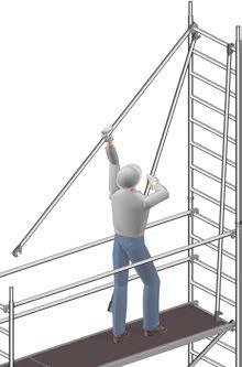
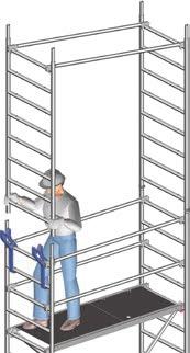
6 3. MEASURES TO PREVENT FALLS Preventing falls during assembly, modification or dismantling of the rolling tower General Suitable measures to prevent falls must be taken during assembly, modification or dismantling of the tower. The safety assembly P2 implements these protective measures in full. Depending on the result of the risk assessment performed, PSA, an AGR or a combination of both can be used m Platform area Attachment points for the personal safety apparatus (PSA) on the rolling tower The rolling tower can also be assembled and dismantled optionally with personal safety apparatus (PSA). The snap hook must be attached during ascent at least 1.0 m above the platform area of the level which has not yet been secured (Fig. 1). The platform height must be at least 5.75 m. The result is the minimum attachment height for PSA of 6.75 m (Fig. 2) m Fig. 2: Minimum heights for use of PSA The tower level can then be made safe with the guardrails. Fig. 1: Attachment of PSA during ascent to the unsecured level Fig. 3: Safe fitting of guardrails with PSA 6
 or b) must be used depending on local regulations. a. Advance guardrail post with connection for telescoping guardrail at 1 m height a.")


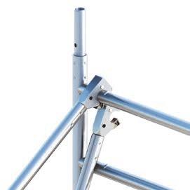
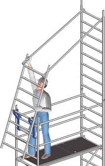
7 Mode of operation of the Layher Advance Guardrail (AGR) The Layher advance guardrail consists of two basic components advance guardrail post and telescoping guardrail. The advance guardrail post a) or b) must be used depending on local regulations. a. Advance guardrail post with connection for telescoping guardrail at 1 m height a. Advance guardrail post with connection for telescoping guardrail at 0.5 and 1 m heights c. Telescoping guardrail made of aluminium Fig. 5: Moving the AGR upwards a b c The post of the AGR rail can be fitted and dismantled by an erector from two positions: 1. Fitting/dismantling from above 2. Fitting/dismantling from below It must be ensured that both claws of the advance guardrail snap in completely and that the telescoping guardrail is attached using the tilting pins. To prevent any unintended slippage of the advance guardrail post, a guardrail must be fitted at the level of a snap-on claw. Fig. 4: Connection of advance guardrail post to ladder frame Fig. 6: Safe fitting of the guardrails with AGR 7
 41.1 57.")

.")
8 4. TOWER MODELS Tower models Design: Safety structure P Arbeitshöhe Gerüsthöhe Standhöhe Tower model Working height [m] Tower height [m] Platform height [m] Weight [kg] (without ballast) Ballasting In closed areas Assembly central l4 r4* l6 r6 0 l2 r2 l4 r4 l4 r4 Assembly off-centre X X L0 R2 L0 R4 L0 R6 L0 R8 Assembly off-centre with wall bracing l4 r0* l6 r0 0 L2 R0 L6 R0 L8 R0 In the open Assembly central l4 r4* l6 r6 0 l2 r2 l4 r4 l4 r4 Assembly off-centre X X L0 R2 L0 R6 L0 R8 X Assembly off-centre with wall bracing l4 r0* l6 r0 0 L4 R0 L8 R0 L16 R0 * The specified ballast weights are only necessary when the ladder frame is used for external access (e.g. standard is swung out). X = not permissible / not possible 0 = no ballast required Specified as single ballast weights of 10 kg each. For ballasting, use Layher ballast weights, Ref. No , of 10 kg each. The weights are fastened quickly and securely at the right place using the hand-wheel coupler. No liquid or granular ballast substances may be used. The ballast weights must be distributed evenly to all ballasting fixing points (see pages 22 23) Example: l2, r2 2 ballast weights of 10 kg each must be fastened to the left-hand side of the ladder frame, and 2 ballast weights of 10 kg each to the right-hand side L6, R16 6 ballast weights of 10 kg each must be fastened to the left-hand side of the mobile beam, and 16 ballast weights of 10 kg each to the right-hand side r and R relate in the case of lateral assembly always to the side facing away from the tower; l and L relate to the side facing the tower (see also Section 9, Ballasting, on pages 22 23) 8
![Tower models Design: Minimum requirements according to DIN EN 1004 620 625 Arbeitshöhe Gerüsthöhe 620 621 Standhöhe 622 623 624 625 Tower model 620 621 622 623 624 625 Working height [m] 2.86 3.61 4.](/docs-images/72/66281746/images/9-0.jpg "11 4.26 5.76 7.26 Tower height [m] 1.83 2.83 3.33 3.48 4.98 6.48 Platform height [m] 0.86 1.61 2.11 2.26 3.76 5.26 Weight [kg] (without ballast) 41.1 57.2 85.3 114.6 141.8 201.")


 Example: l2, r2 2 ballast weights of 10 kg each must be fastened to the left-hand side of the ladder")
9 Tower models Design: Minimum requirements according to DIN EN Arbeitshöhe Gerüsthöhe Standhöhe Tower model Working height [m] Tower height [m] Platform height [m] Weight [kg] (without ballast) Ballasting In closed areas Assembly central l4 r4* l6 r6 l8 r8 0 l2 r2 l4 r4 Assembly off-centre X X X 0 L0 R4 L0 R8 Assembly off-centre with wall bracing l4 r0* l6 r0 l8 r0 0 L4 R0 L8 R0 In the open Assembly central l4 r4* l6 r6 l8 r8 0 l2 r2 l4 r4 Assembly off-centre X X X 0 L0 R4 L0 R10 Assembly off-centre with wall bracing l4 r0* l6 r0 l8 r0 0 L4 R0 L8 R0 * The specified ballast weights are only necessary when the ladder frame is used for external access (e.g. standard is swung out). X = not permissible / not possible 0 = no ballast required Specified as single ballast weights of 10 kg each. For ballasting, use Layher ballast weights, Ref. No , of 10 kg each. The weights are fastened quickly and securely at the right place using the hand-wheel coupler. No liquid or granular ballast substances may be used. The ballast weights must be distributed evenly to all ballasting fixing points (see pages 22 23) Example: l2, r2 2 ballast weights of 10 kg each must be fastened to the left-hand side of the ladder frame, and 2 ballast weights of 10 kg each to the right-hand side L6, R16 6 ballast weights of 10 kg each must be fastened to the left-hand side of the mobile beam, and 16 ballast weights of 10 kg each to the right-hand side r and R relate in the case of lateral assembly always to the side facing away from the tower; l and L relate to the side facing the tower (see also Section 9, Ballasting, on pages 22 23) 9
 145.5 174.6 197.2 223.0 245.")

10 Tower models Design: Safety structure P Arbeitshöhe Gerüsthöhe Standhöhe Tower model Working height [m] Tower height [m] Platform height [m] Weight [kg] (without ballast) Ballasting In closed areas Assembly central l2 r2 l2 r2 Assembly off-centre L0 R4 L0 R6 L0 R8 L0 R10 L0 R14 Assembly off-centre with wall bracing In the open Assembly central 0 0 l2 r2 l4 r4 l8 r8 Assembly off-centre L0 R6 L0 R10 L0 R12 L0 R18 L0 R22 Assembly off-centre with wall bracing X = not permissible / not possible 0 = no ballast required Specified as single ballast weights of 10 kg each. For ballasting, use Layher ballast weights, Ref. No , of 10 kg each. The weights are fastened quickly and securely at the right place using the hand-wheel coupler. No liquid or granular ballast substances may be used. The ballast weights must be distributed evenly to all ballasting fixing points (see pages 22 23) Example: l2, r2 2 ballast weights of 10 kg each must be fastened to the left-hand side of the ladder frame, and 2 ballast weights of 10 kg each to the right-hand side L6, R16 6 ballast weights of 10 kg each must be fastened to the left-hand side of the mobile beam, and 16 ballast weights of 10 kg each to the right-hand side r and R relate in the case of lateral assembly always to the side facing away from the tower; l and L relate to the side facing the tower (see also Section 9, Ballasting, on pages 22 23) 10
11 5. ASSEMBLY SEQUENCE Safety structure P2 Observe the general instructions for assembly and use on pages 4 5. The snap-on claws of all parts must be snapped into the ladder frames from above. Level the tower after the safety assembly. The castors must be locked during assembly, modification or dismantling and while there is anybody on the tower. Hammer home the wedges in the system until the blow bounces off. Screw couplers must always be well tightened (50 Nm). At the top tower level, a double guardrail 17 or a tower beam 18 can be fitted instead of two single guardrails. Please remember in this case that two additional guardrails must be provided for assembly and dismantling in order to ensure collective side protection. They can be removed again after insertion of the double guardrail or tower beam. 1. Pull the basic tower 9 open and firmly snap in the joints in the folding part. 2. Snap the deck 23 into the cross-rungs of the basic tower. To do so, only the 1st, 2nd or 3rd rung from below may be used. 3. Insert castors 1 into the ladder frames of the basic tower 9 and use bolts and nuts to prevent them falling out. Basic structure Tower model Basic structure Tower model Pull the basic tower 9 open and firmly snap in the joints in the folding part. 2. Snap the access deck 24 into the top cross-rung of the basic tower. 3. Insert castors 1 into the ladder frames of the basic tower 9 and use bolts and nuts to prevent them falling out. 4. Fit two 1.00 m ladder frames 10 onto the basic tower 9 and brace them with two guardrails 16. Secure the ladder frame joints with spring clips


12 Basic structure Tower models and Insert the castors 1 into the mobile beam 7 and use bolts and nuts to prevent them falling out. 2. The mobile beams 7 must be connected to one another using a basic tube Pull open the basic tower 9, firmly snap in the joints in the folding part and fit it onto the mobile beams Brace the basic tower by installing a guardrail 16 at the bottom rung. 1. Insert the castors 1 into the mobile beams 7 and use bolts and nuts to prevent them falling out. 2. The mobile beams 7 must be connected to one another using a basic tube Pull open the basic tower 9, firmly snap in the joints in the folding part and fit it onto the mobile beams Snap in the deck 23 at the second rungs of the basic tower ladder frames. Basic structure Tower models and Snap in the access deck 24 at the top rung of the basic tower ladder frames. 6. Attach the 1.95 m diagonal brace 20 to the second rung from the top and to the second rung from the bottom of the opposite ladder frame. 7. Fit two 1.00 m ladder frames 10 and connect them with two guardrails 16 each per side. Secure the ladder frame joints with spring clips


. 3.")

13 Assembly of intermediate platforms All tower models Repeat the following assembly steps 1 to 5 several times depending on the assembly height. 1. Fit a first 2.00 m ladder frame 11 and secure it using spring clips Attach the Uni assembly hooks 29 and position the second ladder frame 11 for assembly of the guardrails Insert diagonal braces 19 and access deck 24. The diagonal bracing arrangement is shown for the tower models (Section 4). 3. Swing the ladder frame 11 with guardrails 16 upwards, fit it in place and secure it with spring clips. 5. Ascend to the next level and fit additional guardrails 16 on the second rung above the platform area. 13
14 Completing the working platform All tower models 6. DISMANTLING SEQUENCE Safety structure P2 Dismantling is performed in the reverse order to assembly (see page 11). When dismantling, do not remove the bracing elements such as diagonal braces, guardrails or access decks until the ladder frames above them have been dismantled. To lift out the individual parts, open the snap-on claws by pressing their locking clips. 1. To complete the working platform, attach toe boards with claw 25 and end toe boards 26. If an intermediate platform is also to be used for working, toe boards must be attached here too. Operating the castors During assembly, dismantling and while working, the castors must be kept locked by pressing down the brake lever labelled STOP. When the brake is locked, the lever labelled STOP is in the down position. For movement, the castors are unlocked by pulling the lever up. The red locking clips of the decks permit effortless installation and removal by a single person; first open them and place the deck with the opened clips on the rung, then open the opposite clips and lift out the deck. Dismantling of working or intermediate platform in Zifa P2 tower When an intermediate platform or working platform is dismantled, the top guardrails are dismantled from the level underneath. This is achieved with the aid of a guardrail installed at knee level. It is placed onto the second rung from above and acts as a lever for opening the snap-on claw (see detail). 14
15 15


16 7. ASSEMBLY SEQUENCE according to DIN EN 1004 Observe the general instructions for assembly and use on pages 4 5. The snap-on claws of all parts must be snapped into the ladder frames from above. Level the tower after the safety assembly. The castors must be locked during assembly, modification or dismantling and while there is anybody on the tower. Hammer home the wedges in the system until the blow bounces off. Screw couplers must always be well tightened (50 Nm). 1. Pull the basic tower 9 open and firmly snap in the joints in the folding part. 2. Snap the deck 23 or access deck 24 into the cross-rungs of the basic tower. To do so, only the 1st, 2nd or 3rd rung from below may be used. 3. Insert castors 1 into the ladder frames of the basic tower 9 and use bolts and nuts to prevent them falling out. Assembly Tower model 621 At the top tower level, a double guardrail 17 or a tower beam 18 can be fitted instead of two single guardrails. Assembly Tower model Pull the basic tower 9 open and firmly snap in the joints in the folding part. 2. Snap the access deck 24 into the top cross-rung of the basic tower. 3. Insert castors 1 into the ladder frames of the basic tower 9 and use bolts and nuts to prevent them falling out. 4. Fit two 1.00 m ladder frames 10 onto the basic tower 9 and brace them with two guardrails. Secure the ladder frame joints with spring clips


17 Assembly Tower model Open the second basic tower 9 and firmly snap in the joint in the folding part. Attach it at an angle of 180 to the first basic tower. Secure the joints with spring clips Snap in the access deck 24 at the second cross-rung from the bottom of the upper basic tower To complete the working platform, install 3 guardrails 16, toe boards 25 and end toe boards Pull open the basic tower 9, firmly snap in the joints in the folding part and brace it with a guardrail 16 at the bottom cross-rung. Basic structure Tower models 623, 624 and Insert castors 1 into the ladder frames of the basic tower 9 and use bolts and nuts to prevent them falling out. Tower model Insert the castors 1 into the mobile beams 7 and use bolts and nuts to prevent them falling out. For basic assembly of the tower model 625, the mobile beams must be additionally connected with a basic tube 12 and the ladder frames provided with a horizontal diagonal brace. 2. Pull open the basic tower 9, firmly snap in the joints in the folding part, brace it with a guardrail 16 at the bottom cross-rung and fit it onto the mobile beams 7. 17


18 Further assembly Tower model 623 Further assembly Tower model Open the second basic tower 9 and firmly snap in the joint in the folding part. Attach it at an angle of 180 to the first basic tower. Secure the joints with spring clips Snap in the access deck 24 at the second cross-rung from below of the upper basic tower. 3. To complete the working platform, install 3 guardrails 16, toe boards 25 and end toe boards Open the second basic tower 9 and firmly snap in the joint in the folding part. Attach it at an angle of 180 to the first basic tower. Secure the joints with spring clips 15. During assembly and dismantling, system decks or scaffolding planks according to DIN (minimum dimensions 28 x 4.5 x 220 cm) must be installed as auxiliary decks at maximum height intervals of 2.0 m. These auxiliary decks provide a safe footing for assembly and dismantling, and must be removed again after assembly. Each platform must be completely boarded. 18

19 2. Fasten a diagonal brace 20 to the bottom rung of the first basic tower and to the second rung from below of the second basic tower. Further assembly Tower model Snap in the access deck 24 at the second cross-rung from below of the upper basic tower. 4. Open the third basic tower 9 and firmly snap in the joint in the folding part. Attach it at an angle of 180 to the second basic tower. Secure the joints with spring clips Fasten a diagonal brace 19 to the bottom rung of the second basic tower and to the second rung from below of the third basic tower. Install the diagonal brace opposite to the first diagonal brace. 6. To complete the working platform, install 3 guardrails 16, toe boards 25 and end toe boards Open the second basic tower 9 and firmly snap in the joint in the folding part. Attach it at an angle of 180 to the first basic tower. Secure the joints with spring clips
 must be installed as auxiliary decks at maximum height intervals of 2.0 m.")


20 During assembly and dismantling, system decks or scaffolding planks according to DIN (minimum dimensions 28 x 4.5 x 220 cm) must be installed as auxiliary decks at maximum height intervals of 2.0 m. These auxiliary decks provide a safe footing for assembly and dismantling, and must be removed again after assembly. Each platform must be completely boarded. Completing the working platform All tower models 2. Fasten a diagonal brace 19 to the bottom rung of the first basic tower and to the second rung from below of the second basic tower. 3. Snap in the access deck 24 at the second cross-rung from the bottom of the second basic tower, then ascend and provide the regulation side protection by installing three guardrails Open the third basic tower 9 and firmly snap in the joint in the folding part. Attach it at an angle of 180 to the second basic tower. Secure the joints with spring clips Fasten the diagonal brace 19 to the third rung from below of the second basic tower and to the third rung from above of the third basic tower, opposite to the first diagonal brace. 6. Install two guardrails 16 to the top rung of the second basic tower as bracing. 7. Open the fourth basic tower 9 and firmly snap in the joint in the folding part. Attach it at an angle of 180 to the third basic tower. Secure the joints with spring clips Fasten a diagonal brace 19 to the bottom rung of the third basic tower and to the second rung from below of the fourth basic tower, opposite to the second diagonal brace. 9. Snap in the access deck 24 at the second cross-rung from below of the upper basic tower. 10. To complete the working platform, install 3 guardrails 16, toe boards 25 and end toe boards To complete the working platform, attach toe boards with claw 25 and end toe boards 26. If an intermediate platform is also to be used for working, toe boards must be attached here too. Operating the castors During assembly, dismantling and while working, the castors must be kept locked by pressing down the brake lever labelled STOP. When the brake is locked, the lever labelled STOP is in the down position. For movement, the castors are unlocked by pulling the lever up. 20

21 8. DISMANTLING SEQUENCE according to DIN EN 1004 Dismantling is performed in the reverse order to assembly (see page 16). When dismantling, do not remove the bracing elements such as diagonal braces, guardrails or access decks until the basic towers above them have been dismantled. To lift out the individual parts, open the snap-on claws by pressing their locking clips. During assembly and dismantling, system decks or scaffolding planks to DIN (minimum dimensions 28 x 4.5 x 220 cm) must be installed as auxiliary decks at maximum height intervals of 2.0 m. These auxiliary decks provide a safe footing for assembly and dismantling, and must be removed again after assembly. Each platform must be completely boarded. The red locking clips of the decks permit effortless installation and removal by a single person; first open them and place the deck with the opened clips on the rung, then open the opposite clips and lift out the deck. 21


22 9. BALLASTING Attachment of ballast weights Assembly central: directly on baseplates on mobile beams (with and without access ledgers) Assembly off-centre: on mobile beams (with and without access ledgers) l r L l r R L l r R L R L R l r l r l r l r l r l r L R L R Note: For the off-centre assembly variant with wall bracing, the bracing must always be attached on the side "L". 22
![Example for assembly of model 1406215 Assembly outdoors in central position Ballast: see pages 8 10 Tower model 1406215 Working height [m] 6.76 Tower height [m] 5.98 Platform height [m] 4.](/docs-images/72/66281746/images/23-0.jpg "76 Weight [kg] (without ballast) 191.")
23 Example for assembly of model Assembly outdoors in central position Ballast: see pages 8 10 Tower model Working height [m] 6.76 Tower height [m] 5.98 Platform height [m] 4.76 Weight [kg] (without ballast) Ballasting In closed areas Assembly central Assembly off-centre Assembly off-centre with wall bracing In the open Assembly central Assembly off-centre Assembly off-centre with wall bracing l4 r4 L0 R6 L6 R0 l4 r4 L0 R8 L8 R0 23
24 10. STABILIZER ATTACHMENT Before assembly, please note page 11 "Basic assembly for rolling tower models without mobile beams". With this assembly form, the fixed and adjustable mobile beams are dispensed with. They are replaced by extendable stabilizers 27. To ensure that the position cannot change, attach the tower rotation lock 28 to the stabilizer 27 and to the rung of the ladder frame 11. Adjust the tower rotation lock by moving the half-coupler on the stabilizer 27 such that the half-coupler is fastened beneath the first rung of the ladder frame. It must be ensured that the spring clips safely engage in the telescoping parts of the extendable stabilizer. When moving the tower, the stabilizer must not be lifted more than 2 cm off the ground. For work performed on a load-bearing wall, ballasting can be provided in accordance with the ballasting table (see pages 8 10). Free-standing assembly Assembly against a wall Attach a stabilizer 27 to each stringer of the ladder frame 11. To do so, fasten the half-coupler directly underneath the rung of the ladder frame 11. Before tightening the star handles (hand wheels), fix the stabilizers in the right position, against the wall or free-standing, and then tighten them using the star handles. Ensure that the foot is firmly on the ground by sliding the half-coupler on the stabilizer. Fasten the lower half-coupler above the bottom rung of the ladder frame 11 and tighten it with the star handle. The positions of the stabilizers must be set as follows: Free-standing assembly: Assembly against wall: in each case about 60 to the tower longitudinal side (Fig. 7). on the wall side about 90 to the tower end face. Side facing away from wall about 60 to the tower longitudinal side (Fig. 8). The specified angles can be checked after attachment of the stabilizers on the basis of the length dimensions "Spacing L". approx. 60 Spacing L = min m Fig. 7 Fig. 8 approx. 90 Spacing L = min m 24

 which was attached to the wall previously.")
25 11. WALL BRACING (under load) ANCHORING (under load and tension) For work performed on a load-bearing wall, ballasting can be reduced in accordance with the table Ballasting (see pages 8 10). In this case, wall bracing or anchoring must be installed on both ladder frames of the tower. Use the Uni distance tube 22 and fix it to the ladder frame 11 using two couplers 30 in each case. The rubber mount is positioned on the wall (see detail A) to provide support. The mobile beams must be installed here so that they project from the side facing away from the wall. The Uni distance tube, rotated by 180, is used for anchoring and is fitted in an eyebolt (see detail B) which was attached to the wall previously. The alignment of the mobile beam can be ignored in this case. Note: In the case of anchoring, ballasting can be dispensed with. The wall bracing/anchoring must be attached at the height of the top working platform or at most 1 m below that. Detail A Detail B 25
26 12. PARTS LIST Tower models Zifa P2 Tower model Article No Guardrail 1.80 m Diagonal brace 2.50 m Diagonal brace 1.95 m Basic tube 1.80 m End toe board 0.75 m Toe board 1.8 m, with claw Deck 1.8 m Access deck 1.8 m Spring clip Ladder frame 75/ m Ladder frame 75/ m Uni assembly hook Zifa 75 basic tower Castor kn Mobile beam 1.80 m with ledger Ballast For the number of ballasting weights see the ballasting table, page 8 Tower models Zifa minimum requirements according to DIN EN 1004 Tower model Article No Guardrail 1.80 m Diagonal brace 2.50 m Diagonal brace 1.95 m Horizontal diagonal brace 1.95 m Basic tube 1.80 m End toe board 0.75 m Toe board 1.8 m, with claw Deck 1.8 m Access deck 1.8 m Spring clip Ladder frame 75/ m Ladder frame 75/ m Zifa 75 basic tower Castor kn Mobile beam 1.80 m without ledger Ballast For the number of ballasting weights see the ballasting table, page 9 26
27 Tower models Zifa P2 with stabilizers Tower model Article No Guardrail 1.80 m Diagonal brace 2.50 m Diagonal brace 1.95 m End toe board 0.75 m Toe board 1.8 m, with claw Deck 1.8 m Access deck 1.8 m Aluminium tower support, extendable Tower rotation lock Spring clip Ladder frame 75/ m Ladder frame 75/ m Uni assembly hook Zifa 75 basic tower Castor kn Mobile beam 1.80 m without ledger Mobile beam 1.80 m with ledger Ballast For the number of ballasting weights see the ballasting table, page 10 27
. Special wheel for sensitive floor surfaces. Wheel and slewing ring can be locked. Weight 2.5 kg. 1259.")
.")
28 13. COMPONENTS OF THE SYSTEM Castor 400 Plastic wheel dia. 150 mm, with simple brake lever, permissible load 4 kn ( 400 kg), weight 2.2 kg Castor 400 Plastic wheel with Vulkollan tyre, dia. 150 mm, permissible load 4 kn ( 400 kg). Special wheel for sensitive floor surfaces. Wheel and slewing ring can be locked. Weight 2.5 kg Castor 700 with baseplate and lock Plastic wheel dia. 200 mm, permissible load 7 kn ( 700 kg). With double brake lever and load centering in the braked state. Wheel and slewing ring can be locked. Adjustment range m. Weight 6.8 kg Castor 1000 with baseplate and lock Aluminium rim with Vulkollan tyre, dia. 200 mm, permissible load 10 kn ( 1000 kg). With double brake lever and load centering in the braked state. Wheel and slewing ring can be locked. Adjustment range m, weight 9.4 kg Mobile beam w. ledger 1.8 m Steel rectangular tube, hot-dip-galvanized. For widening the base of towers with up to 6.6 m platform height. Width 1.8 m, weight 16.8 kg Mobile beam 1.8 m Steel rectangular tube, hot-dip-galvanized. For widening the base of towers with up to 6.6 m platform height. Width 1.8 m, weight 14.4 kg Castor 700 with baseplate and lock Plastic wheel with Vulkollan tyre, dia. 200 mm, permissible load 7 kn 7 kn ( 700 kg). With double brake lever and load centering in the braked state. Wheel and slewing ring can be locked. Adjustment range m, weight 7.0 kg Zifa 75 basic tower, aluminium. Width 0.75 m, length 1.8 m, height 1.5 m. Dimensions when folded together: 0.95 x 1.5 x 0.3 m, weight 20.2 kg Castor 1000 with baseplate and lock Plastic wheel dia. 200 mm, permissible load 10 kn ( 1000 kg). With double brake lever and load centering in the braked state. Wheel and slewing ring can be locked. Adjustment range m, weight 9.4 kg Ladder frame 75/4 aluminium. Rungs with non-slip grooving. Height 1.0 m, width 0.75 m, weight 4.7 kg. 28
29 Ladder frame 75/8 aluminium. Rungs with non-slip grooving. Height 2.0 m, width 0.75 m, weight 8.6 kg Double guardrail 1.8 m aluminium. Length 1.8 m, height 0.5 m, weight 5.8 kg Basic tube 1.8 m steel tube, hot-dip-galvanized. Length 1.8 m, weight 7.7 kg Beam 1.8 m aluminium. Support elements in tower construction kit or double side protection. Length 1.8 m, height 0.5 m, weight 7.2 kg Access ledger 0.3 aluminium, length 0.27 m, weight 2.9 kg Diagonal brace 2.5 m aluminium. Length 2.5 m, weight 3.3 kg Ballast (10 kg) steel, hot-dip-galvanized with half-coupler Diagonal brace 1.95 m aluminium. Length 1.95 m, weight 2.8 kg Spring clip steel. Weight 0.1 kg Horizontal diagonal brace 1.95 m aluminium. Length 1.95 m, weight 3.5 kg Guardrail 1.8 m aluminium. Length 1.8 m, weight 2.3 kg Uni distance tube Aluminium tube with hook and rubber foot. dia mm, Length 1.1 m, weight 1.4 kg. 29


30 für fahrbare Arbeitsbühnen (Fahrgerüste) nach DIN EN 1004 Gerüst-Ersteller: befähigte Person beim Aufbau: Aufbauzeitraum: befähigte Person zur Prüfung: Telefonnummer: Prüfungszeitraum: Erstellungsort: Gerüst-Nr.: Gerüstgruppe: 2 (150 kg/m²) 3 (200 kg/m²) Die Summe der Verkehrslasten aller übereinanderliegenden Gerüstlagen in einem Gerüstfeld darf den vorgenannten Wert nicht überschreiten. Zugangstyp: A Treppe B Stufenleiter C Schrägleiter D Vertikalleiter Höchstzulässige Standhöhe gemäß Aufbau- und Verwendungsanleitung außerhalb von Gebäuden: m innerhalb von Gebäuden: m Nutzungsbeschränkungen für den Nutzer: Geprüft und freigegeben befähigte Person des Gerüst-Erstellers: Datum, Unterschrift Wilhelm Layher GmbH & Co. KG Gerüste Tribünen Leitern Ochsenbacher Straße 56 D Güglingen-Eibensbach Auftraggeber: Telefonnummer: Eigenmächtige Änderungen am Gerüst sind ohne vorige Rücksprache mit dem Gerüst-Ersteller untersagt! Während dem Arbeiten auf dem Gerüst sind die Lenkrollen zu arretieren. Die Anweisungen für den Aufbau und Gebrauch sind sorgfältig zu befolgen! befähigte Person des Nutzers: Datum, Unterschrift Bemerkungen, Hinweise: Geprüft und freigegeben befähigte Person des Gerüst-Erstellers: Datum, Unterschrift nach 10 und 11 BetrSichV Gerüst-Nr.: Ja Nein Gerüstbauteile augenscheinlich unbeschädigt Lenkrollen Tragfähigkeit geeignet mit Feststellbremse versehen / mit Feststellschraube gegen Lösen gesichert Standleitern Leiternpaare doppelt ausgesteift Horizontalaussteifung in der Basiskonstruktion Ständerstöße gesichert (Federstecker) Böden Böden / Durchstiege in ausreichender Anzahl / Abstand Zugänge Treppe, Stufenleiter, Schrägleiter oder Vertikalleiter vorhanden Seitenschutz auf allen Arbeitsebenen 3-teiliger Seitenschutz angebracht Ballast Ballastierung gemäß AuV Verbreiterung geeignet für Höhe Sonderaufbauten Übereinstimmung mit AuV / Typenstatik befähigte Person des Nutzers: Datum, Unterschrift Deck 1.8 m Aluminium frame, with plywood deck (BFU 100 G) with phenolic resin coating. Length 1.8 m, width 0.68 m, weight 13.3 kg / Special screw coupler, rigid 19 or 22 mm WS, weight 1.1 kg Prohibition sign Access deck 1.8 m Aluminium frame, with plywood deck and hatch (BFU 100 G) with phenolic resin coating. Length 1.8 m, width 0.68 m, weight 15.0 kg. 32 Kennzeichnung und Freigabe Prüfprotokoll / Identification notice for rolling towers Toe board 1.8 m with claw wood. Length 1.8 m, height 0.15 m, weight 4.2 kg End toe board 0.75 m wood. Length 0.73 m, height 0.15 m, weight 1.6 kg Stabilizer, extendable aluminium. Length 2.6 m, weight 8.5 kg Rotation lock aluminium. Length 0.5 m, weight 2.8 kg Uni assembly hook polyethylene, Set of 2. Weight 1.2 kg. 30
31 14. CERTIFICATE 31
32 Wilhelm Layher GmbH & Co. KG Scaffolding Grandstands Ladders Ochsenbacher Strasse 56 D Gueglingen-Eibensbach Germany P.O. Box 40 D Güglingen-Eibensbach Germany Telephone +49 (0) Telefax +49 (0)
Rolling Towers. Layher Rolling Towers Uni Wide. Safety Structure Instructions for Assembly and Use. Mobile working platforms to DIN EN 1004:
 Layher Rolling Towers Uni Wide Safety Structure Instructions for Assembly and Use Mobile working platforms to DIN EN 1004:2005-03 Working platform 1.5 x 2.85 m Rolling Towers max. working height: indoors
Rolling Towers. Layher Uni Light Tower Instructions for Assembly and Use. Mobile working platforms according to DIN EN 1004:
 Instructions for ssembly and Use Mobile working platforms according to DIN EN 00:00-03 Working platform 0.7 x.8 m max. working height: indoors.3 m outdoors.3 m Rolling Towers Load bearing capacity.0 kn/m
Layher SpeedyScaf Instructions for Assembly and Use
 Layher SpeedyScaf Instructions for Assembly and Use Edition 11.2013 Ref. No. 8102.230 Quality management certified according to DIN EN ISO 9001:2008 by TÜV-CERT Contents 1. Introduction... 4 2. Measures
Layher. Aluminium Rolling Towers. Layher SuperKlaxTower. Instructions for Assembly and Use
 Mobile access and working towers in accordance with: HD 1004; DIN 4422, Part 1 (Version 8/92) Working platform 2.8 x 2.8 m and 2.8 x 1.95 m Max. working height: in closed rooms 13.95 m, outdoors 10.0 m
Accessories. Layher Railing clamp Instructions for Assembly and Use. Quality management certified as per DIN ISO 9001:2008 by TÜV-CERT
 Layher Railing clamp Instructions for Assembly and Use Quality management certified as per DIN ISO 9001:2008 by TÜV-CERT Accessories BAU/TB...1) Sicherheit geprüft tested safety } Contents 1. General information...2
Allround Scaffolding. Layher Allround Bridging System Instructions for Assembly and Use. Modular truss system for wide spans
 Layher Allround Bridging System Instructions for Assembly and Use Modular truss system for wide spans Certification according to DIN ISO 9001/EN 29 001 by TÜV-CERT Allround Scaffolding } CONTENT 1. Introduction...3
Layher. Keder Roof and Keder Hall. More Possibilities. The Scaffolding System. Layher Keder Roof and Keder Hall Instructions for Assembly and Use
 Layher Keder Roof and Keder Hall Instructions for Assembly and Use Certification as per DIN ISO 9001/EN 29 001 by TÜV-CERT Keder Roof and Keder Hall Layher More Possibilities. The Scaffolding System. CONTENTS
LAYHER ACCESS TECHNOLOGY CATALOGUE
 LAYHER ACCESS TECHNOLOGY CATALOGUE Edition 04.2018 Ref. No. 8118.229 Quality management certified according to ISO 9001:2008 ROLLING TOWERS FROM PAGE 34 ALU BRIDGING BEAM FROM PAGE 24 NOTICE All dimensions
Edition Ref. No Quality management certified according to ISO 9001:2008 by German TÜV-CERT
 LAYHER Allround Scaffolding Safety in Industrial Applications // Layher Allround Scaffolding O-Version Edition 05.2013 Ref. No. 8116.241 Quality management certified according to ISO 9001:2008 by German
Edition Ref. No Quality management certified according to ISO 9001:2008 by German TÜV-CERT
 LAYHER Allround Scaffolding Safety in Industrial Applications // Layher Allround Scaffolding U-Version Edition 05.2013 Ref. No. 8116.240 Quality management certified according to ISO 9001:2008 by German
This User Guide provides you with step by step instructions to ensure your system is erected easily and safely.
 INTRODUCTION Please read this guide carefully. Please note that diagrams are for illustrative purposes only. Trade King 730 mobile aluminium towers are light-weight scaffold towers used throughout the
Edition Ref. No Quality management certified according to ISO 9001:2008 by German TÜV-CERT
 LAYHER Allround scaffolding shoring tg 60 Edition 04.2013 Ref. No. 8116.206 Quality management certified according to ISO 9001:2008 by German TÜV-CERT Allround Scaffolding Layher Allround Scaffolding the
LAYHER ALLROUND SCAFFOLDING SHORING TG 60
 LAYHER ALLROUND SCAFFOLDING SHORING TG 60 Edition 05.2015 Ref. No. 8116.206 Quality management certified according to ISO 9001:2008 by German TÜV-CERT Allround Scaffolding LAYHER ALLROUND SCAFFOLDING THE
LADDERSPAN AGR. BoSS Camlock Advance Guardrail Mobile Aluminium Tower 1450/850 Frames USER GUIDE
 LADDERSPAN AGR BoSS Camlock Advance Guardrail Mobile Aluminium Tower 1450/850 Frames USER GUIDE Contents Safety First Safety Checklist Quantity Schedules Assembly and Dismantling Procedure Toe Boards Stabilisers
Span 400 Instruction Manual
 Span 400 Instruction Manual DESIGNATION SPAN 400 Double Width EN 004 3 8/2 XXCD SPAN 400 Single Width EN 004 3 8/8 XXCD CEN designation of this instruction manual EN 298 IM en Rev-00 WARNING NEVER STAND
MiniMax USER GUIDE. Mobile Aluminium Trade Quality Access Tower System. 3T - Through The Trapdoor Method
 MiniMax Mobile Aluminium Trade Quality Access Tower System 3T - Through The Trapdoor Method USER GUIDE Contents Safety First Component Diagram Component Quantity & Safety Data Schedule Build Method Pre-use
Span 300 Manual. DESIGNATION EN1004 CEN 1298 IM - en. CEN designation of this instruction manual EN 1298 IM en
 Span 300 Manual DESIGNATION EN1004 CEN 1298 IM - en CEN designation of this instruction manual EN 1298 IM en WARNING NEVER STAND ON AN UNGUARDED PLATFORM SAFE WORKING LOADS AND WORKING HEIGHTS The safe
LAYHER ALLROUND SCAFFOLDING INSTRUCTIONS FOR ASSEMBLY AND USE
 LAYHER ALLROUND SCAFFOLDING INSTRUCTIONS FOR ASSEMBLY AND USE Edition 05.2013 Ref. No. 8116.230 Quality management certified according to DIN EN ISO 9001:2008 by TÜV-CERT CONTENTS 1. Introduction... 4
CLIMA AGR. Mobile Aluminium Tower with Climbing Frames 1450/850 Camlock Advanced Guardrail USER GUIDE
 CLIMA AGR Mobile Aluminium Tower with Climbing Frames 1450/850 Camlock Advanced Guardrail USER GUIDE Contents Safety First Safety Checklist Quantity Schedules Assembly and Dismantling Procedure Toe Boards
Mobile Tower 3T Method (Through The Trapdoor) Please read this guide carefully. Please note that diagrams are for illustrative purposes only.
 Please read this guide carefully. Please note that diagrams are for illustrative purposes only.") Mobile Tower 3T Method (Through The Trapdoor) INTRODUCTION Please read this guide carefully. Please note that diagrams are for illustrative purposes only. LOYAL mobile aluminium towers are light-weight
Mobile Tower 3T Method (Through The Trapdoor) INTRODUCTION Please read this guide carefully. Please note that diagrams are for illustrative purposes only. LOYAL mobile aluminium towers are light-weight
Span 300 Instruction Manual
 Span 300 Instruction Manual DESIGNATION SPAN300 Double Width EN 1004 3 8/12 XXCD SPAN 300 Single Width EN 1004 3 8/8 XXCD CEN designation of this instruction manual EN 1298 IM en Rev-00 WARNING NEVER STAND
8 Rung Industrial Tower
 A SAFER WAY TO REACH NEW HEIGHTS 8 Rung Industrial Tower Instruction Manual Mobile Access Tower 3T - Through the trap method Introduction This Assembly Guide is intended to provide you with step-by-step
Safety First Mobile Towers - 3T Method
 USER GUIDE Edition Aug 2011 MiniMax Mobile Aluminium Trade Quality Access Tower System 3T - Through the Trapdoor Method Safety First Mobile Towers - 3T Method INTRODUCTION Please read this guide carefully.
Span 500. Elite Instruction Manual. DESIGNATION SPAN 500 Double Width EN /12 XXXD SPAN 500 Single Width EN /8 XXXD
 Span 500 Elite Instruction Manual DESIGNATION SPAN 500 Double Width EN 1004 3 8/12 XXXD SPAN 500 Single Width EN 1004 3 8/8 XXXD CEN designation of this instruction manual EN 1298 IM en Rev-02 WARNING
Span 400 Series Instruction Manual
 Span 400 Series Instruction Manual DESIGNATION 400 400 004 3 8 2 400 400 004 3 8 8 CEN designation of this instruction manual EN 298 IM en Rev-0 WARNING NEVER STAND ON AN UNGUARDED PLATFORM SAFE WORKING
ROOM-MATE. 3T - Through the Trapdoor USER GUIDE
 ROOM-MATE 3T - Through the Trapdoor USER GUIDE Safety First Introduction Please read this user guide carefully. Please note that diagrams are for illustrative purposes only. User guides are also available
CLIMA 3T. Mobile Aluminium Tower with Climbing Frame 1450/850 3T - Through the Trapdoor Method USER GUIDE
 CLIMA 3T Mobile Aluminium Tower with Climbing Frame 1450/850 3T - Through the Trapdoor Method USER GUIDE Safety First Mobile Towers - 3T Method Introduction Please read this user guide carefully. Please
1450/850. Instruction Manual. Mobile Access Tower
 A SAFER WAY TO REACH NEW HEIGHTS 1450/850 Instruction Manual Mobile Access Tower 3T - Through the trap method Introduction This Assembly Guide is intended to provide you with step-by-step instructions
Mobile Towers - 3T Method
 Safety First Safety First INTRODUCTION SAFE USE Mobile Towers - 3T Method Please read this guide carefully. Please note that diagrams are for illustrative purposes only. User guides are also available
Safety First Mobile Towers - 3T Method
 Safety First Mobile Towers - 3T Method INTRODUCTION Please read this guide carefully. Please note that diagrams are for illustrative purposes only. User guides are also available to download from our website
Inspect components prior to erection. Inspect tower prior to use. Castors locked and legs correctly adjusted. Stabilisers fitted as specified
 Introduction This Guide is designed to provide you with step bystep instructions to ensure that your system is erected with themaximum of ease and safety. Before assembly, please read thesafety notes.
Assembly and Usage Instructions Z 600 S-PLUS mobile scaffold tower with stabilisers Z 600 S-PLUS folding scaffold unit COMPACT
 09/2016 No. 291358 en Assembly and Usage Instructions Z 600 S-PLUS mobile scaffold tower with stabilisers Z 600 S-PLUS folding scaffold unit COMPACT 2 Contents en 1 General information... 4 1.1 Introduction...4
CLIMA 3T. Mobile Aluminium Tower with Climbing Frame 1450/850 3T - Through the Trapdoor Method USER GUIDE
 CLIMA 3T Mobile Aluminium Tower with Climbing Frame 1450/850 3T - Through the Trapdoor Method USER GUIDE Safety First Mobile Towers - 3T Method INTRODUCTION Please read this Userguide carefully. Please
SOLO 700. One Man Aluminium Tower 3T - Through the Trapdoor Method USER GUIDE
 SOLO 700 One Man Aluminium Tower 3T - Through the Trapdoor Method USER GUIDE Contents Safety First Component Diagram Quantity Schedules Stabilisers Build Method 2 7 9 10 11 1 BoSS SOLO 700 User Guide Safety
LEWIS Miniscaff Folding Tower Assembly Guide
 LEWIS Miniscaff Folding Tower Assembly Guide This document is a complete guide for the LEWIS Miniscaff Towers The user should read the entire contents of this document before commencing assembly and pay
USER S MANUAL HAKI PUBLIC ACCESS STAIR
 USER S MANUAL HAKI PUBLIC ACCESS STAIR HAKI AB 2017 Important information HAKI s product liability and user s manuals apply only to scaffolds that are entirely composed of components that have been made
Safety First Mobile Towers - 3T Method INTRODUCTION
 BoSS Room-Mate 3T - Through the Trap Method Safety First Mobile Towers - 3T Method INTRODUCTION Please read this guide carefully. Please note that diagrams are for illustrative purposes only. User guides
Instruction Manual. DESIGNATION SPAN 500 Double Width EN /12 XXXD SPAN 500 Single Width EN /8 XXXD
 Instruction Manual DESIGNATION SPAN 500 Double Width EN 1004 3 8/12 XXXD SPAN 500 Single Width EN 1004 3 8/8 XXXD CEN designation of this instruction manual EN 1298 IM en Rev-02 WARNING NEVER STAND ON
LADDERSPAN 3T USER GUIDE. Mobile Aluminium Tower 1450/850 Ladderspan. 3T - Through the Trapdoor Method
 LADDERSPAN 3T Mobile Aluminium Tower 1450/850 Ladderspan 3T - Through the Trapdoor Method USER GUIDE Safety First Mobile Towers - 3T Method INTRODUCTION Please read this user guide carefully. Please note
BoSS Clima USER GUIDE. Mobile Aluminium Tower with Climbing Frame 1450/850. 3T - Through the Trapdoor Method
 BoSS Clima Mobile Aluminium Tower with Climbing Frame 1450/850 3T - Through the Trapdoor Method USER GUIDE Edition April 2009 Safety First Mobile Towers - 3T Method INTRODUCTION Please read this guide
Assembly and usage instructions. Z600 brace-free mobile scaffold
 Assembly and usage instructions www.zarges.de brace-free mobile scaffold towers Assembly and usage instructions 3 Table of contents 1. General information 4 1.1. Introduction 4 1.2. Manufacturer 4 1.3.
USER S MANUAL HAKI PUBLIC ACCESS STAIR
 USER S MANUAL HAKI PUBLIC ACCESS STAIR HAKI AB 2018 Important information HAKI s product liability and user s manuals apply only to scaffolds that are entirely composed of components that have been made
INSTRUCTION MANUAL MOBILE ACCESS TOWER
 INSTRUCTION MANUAL MOBILE ACCESS TOWER CONTENTS Safety First.......... 3-6 Component Diagrams......... 7-9 Component Quantity & Safety Data Schedule.... 10 Build Method.......... 11-24 Pre-use Safety Inspection
USER S MANUAL. HAKI Loading Tower
 USER S MANUAL HAKI Loading Tower HAKI AB 2018 Important information HAKI s product liability and user s manuals apply only to scaffolds that are entirely composed of components that have been made and
BoSS. Mobile Aluminium Tower 1450/850 Ladderspan. 3T - Through the Trapdoor Method
 BoSS Mobile Aluminium Tower 1450/850 Ladderspan 3T - Through the Trapdoor Method USER GUIDE Edition November 2011 Safety First Mobile Towers - 3T Method INTRODUCTION Please read this guide carefully. Please
MOBILE ACCESS TOWER INSTRUCTION MANUAL SHALLOW BRACE. Incorporating the 3T method of assembly
 MOBILE ACCESS TOWER Incorporating the 3T method of assembly SHALLOW BRACE INSTRUCTION MANUAL 2 INTRODUCTION This instruction manual contains all the information required to correctly assemble the OCTO
Industrial Aluminium Towers
 Industrial Aluminium Towers SINGLE WIDTH LADDERSPAN & VERTICAL LADDER ERECTION MANUAL HORIZONTAL BRACE 1.8m (2040) 2.7m (2041) REVISED EDITION TOE BOARD 1.8m (2065) 2.7m (2067) LADDERSPAN TRAP PLATFORM
BoSS SOLO 700. One Man Aluminium Tower EN /4 EN1298-IM-EN 3T - Through the Trap Door USER GUIDE
 BoSS SOLO 700 One Man Aluminium Tower EN1004-3-4/4 EN1298-IM-EN 3T - Through the Trap Door USER GUIDE Edition August 2013 Contents Safety First 2 Component Diagram 7 Quantity Schedules 9 Stabalisers 10
AGR TOWER. Standard Features include. Tower Assembly Training Available
 AGR TOWER The Euro Tamper Proof Advanced Guardrail is another solution to safe tower assembly. The ergonomic design lends itself to quick easy assembly and provides collective fall prevention before the
SAFE ERECTION AND USE OF ALUMINIUM TOWERS/SCAFFOLDS
 SAFE ERECTION AND USE OF ALUMINIUM TOWERS/SCAFFOLDS PERSONNEL DIVISION Revised 2002 CONTENTS Page 1 INTRODUCTION 1 2 APPLICATION 1 3 ERECTION AND INSPECTION 1 4 ERECTION 1 4.1 Before erection of tower
USER S Manual. HAKI Bridge System (HBS)
") USER S Manual HAKI Bridge System (HBS) HAKI AB 2018 Important information HAKI s product liability and user s manuals apply only to scaffolds that are entirely composed of components that have been made
USER S Manual HAKI Bridge System (HBS) HAKI AB 2018 Important information HAKI s product liability and user s manuals apply only to scaffolds that are entirely composed of components that have been made
BoSS Room-Mate. 3T - Through the Trap Method
 BoSS Room-Mate 3T - Through the Trap Method User Guide Edition 2: 2010 Safety First Mobile Towers - 3T Method INTRODUCTION Please read this guide carefully. Please note that diagrams are for illustrative
Custers. Camino CHIMNEY SCAFFOLDING ASSEMBLY AND USER S INSTRUCTIONS. Nov. 2003
 ASSEMBLY AND USER S INSTRUCTIONS Custers Camino CHIMNEY SCAFFOLDING 9505.903.001 ENG / (9505.202.015/016) Nov. 2003 CUSTERS HYDRAULICA B.V. Smakterweg 33, 5804 AE VENRAY NL Telephone : +31 (0) 478 55 30
Safety First Mobile Towers - 3T Method INTRODUCTION
 Safety First Mobile Towers - 3T Method INTRODUCTION Safety First SAFE USE BoSS Mobile Aluminium Tower 1450/850 Ladderspan 3T - Through the Trapdoor Method Please read this guide carefully. Please note
COMPONENT SCHEDULE SINGLE WIDTH SPAN TOWERS WITH LADDER FRAMES TO BSEN RUNG STARTER FRAMES
 COMPONENT SCHEDULE SINGLE WIDTH SPAN TOWERS WITH LADDER S TO BSEN 1004-2004 STARTER S PLATFORM HEIGHT METRIC 2.4 2.9 3.4 3.9 4.4 4.9 5.4 5.9 6.4 6.9 7.4 7.9 DESCRIPTION IMPERIAL 7 10 9 6 11 2 12 10 14
Allround Scaffolding System
 Quality management certified according to ISO 9001:2008 by German TÜV-CERT L i m i t l e s s. S t r o n g. 8116.221 I n g e n i o u s. Catalogue Edition 01.04.2012 Allround Scaffolding System Layher Allround
3T - Through The Trapdoor Method
 ALTO HEAVY DUTY SINGLE WIDTH LADDERSPAN TOWER Mobile Aluminium Access Tower ISSUE 5 Instruction Manual EN 1298-IM-EN The ALTO HD Ladderspan Tower is certified to BS EN 1004:2004 3T - Through The Trapdoor
BoSS Climalite Camera and lighting tower
 Contents Safety First Safety First Quantity Schedules Toeboard 2 9 13 33 INTRODUCTION Please read this guide carefully. Please note that diagrams are for illustrative purposes only. User guides are also
USER S MANUAL HAKI COMPACT STAIR TOWER
 USER S MANUAL HAKI COMPACT STAIR TOWER HAKI AB 2018 Important information HAKI s product liability and user s manuals apply only to scaffolds that are entirely composed of components that have been made
Industrial Aluminium Towers
 Industrial Aluminium Towers SINGLE WIDTH LADDERSPAN & VERTICAL LADDER ERECTION MANUAL TO BS-EN 1004-2004 Using 2 rung frames (Recommended) Using guardrail frames HORIZONTAL BRACE 1.8m (2040) 2.7m (2041)
Safety First Mobile Towers - 3T Method INTRODUCTION. Please read this guide carefully. Please note that diagrams are for illustrative purposes only.
 BoSS Mobile Aluminium Tower 0/80 Ladderspan T - Through the Trapdoor Method Safety First Mobile Towers - T Method INTRODUCTION Please read this guide carefully. Please note that diagrams are for illustrative
A SAFER WAY TO REACH NEW HEIGHTS. Instruction Manual. Mobile Access Tower. 3T - Through the trap method
 A SAFER WAY TO REACH NEW HEIGHTS UTS1450/850 Instruction Manual Mobile Access Tower 3T - Through the trap method Introduction This Assembly Guide is intended to provide you with step-by-step instructions
Industrial Aluminium Towers
 HORIZONTAL 1.8m (2040) 2.7m (2041) TOE BOARD 1.8m (2066) 2.7m (2068) Industrial Aluminium Towers DOUBLE WIDTH SPAN & VERTICAL ASSEMBLY GUIDE TO BS-EN 1004-2004 Using the 3T (Through the Trap ) Assembly
Layher. Cut costs, improve safety, increase efficiency: Layher AllroundScaffolding. Allround Scaffolding
 Cut costs, improve safety, increase efficiency: Layher llroundscaffolding. llround Scaffolding Layher M o r e P o s s i b i l i t i e s. T h e S c a f f o l d i n g S y s t e m. Made by Layher. Supply
 Instruction Manual Span Scaffolds! W A R N I N G! Before using Instant UpRight Scaffolds, read, understand and follow all Safety Rules, Erection Instructions and Maintenance Rules. Keep this manual for
Instruction Manual Span Scaffolds
 Instruction Manual Span Scaffolds QUALITY & STRENGTH YOU CAN TRUST! W A R N I N G! Before using Instant UpRight Scaffolds, read, understand and follow all Safety Rules, Erection Instructions and Maintenance
LAYHER EVENT SYSTEMS CATALOGUE
 LAYHER EVENT SYSTEMS CATALOGUE Edition 04.2015 Ref. No. 8111.227 Quality management certified according to ISO 9001:2008 by German TÜV-CERT Layher QUALITY MADE BY LAYHER Headquarters in Eibensbach Plant
Assembly and usage instructions REACHMASTER
 Assembly and usage instructions REACHMASTER Assembly and usage instructions Assembly and usage instructions 3 Table of contents 1. General information 4 1.1. Introduction 4 1.2. Manufacturer 4 1.3. Type
USER S MANUAL HAKI STAIR TOWER
 USER S MANUAL HAKI STAIR TOWER HAKI AB 2018 Important information HAKI s product liability and user s manuals apply only to scaffolds that are entirely composed of components that have been made and supplied
Snappy Ladder 300 Instruction Manual
 Snappy Ladder 300 Instruction Manual DESIGNATION: SNAPPY LADDER 300 EN 1004 3 4/4 XXCD CEN designation of this instruction manual EN 1298 IM en Rev-01 This assembly instruction is designed to provide a
ASSEMBLY INSTRUCTION ROLLING TOWER RT 1400 & RT 1400XR ROLLING TOWER RT 750 & RT 750XR STAIR TOWER ST 1400 FOLDABLE TOWER FT 750 & FT 750XR
 ASSEMBLY INSTRUCTION ROLLING TOWER RT 1400 & RT 1400XR ROLLING TOWER RT 750 & RT 750XR STAIR TOWER ST 1400 FOLDABLE TOWER FT 750 & FT 750XR EN 1298 - IM - en SC1809 12 SAFETY IN EVERY STEP wibeladders.com
ASSEMBLY.
 ASSEMBLY www.proscaf.com ASSEMBLY SECTION Points to Consider These assembly instructions are generic and may not apply to all applications. If you have questions regarding specific applications contact
USER S MANUAL HAKI COMPACT STAIR TOWER
 USER S MANUAL HAKI COMPACT STAIR TOWER HAKI AB 2018 Important information HAKI s product liability and user s manuals apply only to scaffolds that are entirely composed of components that have been made
GENERAL SAFETY RULES DOUBLE WIDTH 232 (NARROW RUNG) 3T INSTRUCTION MANUAL DISMANTLING NOTES: The 232 Tower Approved to the requirements of BS EN 1004
 3T INSTRUCTION MANUAL DISMANTLING NOTES: The 232 Tower Approved to the requirements of BS EN 1004") GENERAL SAFETY RULES DOUBLE WIDTH 232 (NARROW RUNG) 3T INSTRUCTION MANUAL The 232 Tower Approved to the requirements of BS EN 1004 MAX SAFE WORKING LOAD FOR STRUCTURE: 750KG MAX SAFE WORKING LOAD FOR PLATFORM:
GENERAL SAFETY RULES DOUBLE WIDTH 232 (NARROW RUNG) 3T INSTRUCTION MANUAL The 232 Tower Approved to the requirements of BS EN 1004 MAX SAFE WORKING LOAD FOR STRUCTURE: 750KG MAX SAFE WORKING LOAD FOR PLATFORM:
Industrial Aluminium Towers
 Industrial Aluminium Towers SINGLE WIDTH LADDERSPAN & VERTICAL LADDER ASSEMBLY GUIDE TO BS-EN 1004-2004 Using 2 rung frames (Recommended) Using Guardrail frames HORIZONTAL BRACE 1.8m (2040) 2.7m (2041)
Assembly Instructions
 MULTI-FUNCTIONAL SCAFFOLD UNIT + STABILIZER LEGS 1. SCAFFOLD 2. LADDER 3.TRESTLE 2 1 3 Assembly Instructions CODE: 126431 Parts List Specifications: - Width: 1.2m - Length: 1.6m - Scaffold Height: 3.4m
SYSTEM-FREE ACCESSORIES CATALOGUE
 SYSTEM-FREE ACCESSORIES CATALOGUE Edition 0.20 0.27 Quality management certified according to ISO 900:200 Contents COMPANY FROM MAIN ACCESSORIES FROM PAGE ADVANCED ACCESSORIES PLANNING AND SAFETY FROM
PROFESSIONAL ROLLING TOWER SYSTEMS
 Relax. It s an Altrex. ROLLING TOWER SYSTEMS Rolling tower Folding frame Relax. It s an Altrex. Working at height has several risks. Choosing Altrex is choosing safety, quality and durability. Altrex access
INSTRUCTIONmanual. BoSS COMPACT SIDE CANTILEVER TOWER SCAFFOLD 3T Method - Through the Trap Door
 INSTRUCTIONmanual BoSS COMPACT SIDE CANTILEVER TOWER SCAFFOLD 3T Method - Through the Trap Door Drawn: 26/02/2018 Issue: E Page: 2 OF 21 CONTENTS Safety First Component Diagram Component Quantities & Safety
EASY-SET SCAFFOLD TOWER OPERATIONAL SAFETY AND ASSEMBLY INSTRUCTIONS MODEL: AL-Q0107. Customer Service
 MODEL: AL-Q0107 EASY-SET SCAFFOLD TOWER OPERATIONAL SAFETY AND ASSEMBLY INSTRUCTIONS Picture may differ from actual product. READ THESE INSTRUCTIONS CAREFULLY BEFORE USING THIS PRODUCT. KEEP THIS MANUAL
EASY-SET SCAFFOLD TOWER OPERATIONAL SAFETY AND ASSEMBLY INSTRUCTIONS MODEL: AL-Q0106. Customer Service
 MODEL: AL-Q0106 EASY-SET SCAFFOLD TOWER OPERATIONAL SAFETY AND ASSEMBLY INSTRUCTIONS Picture may differ from actual product. READ THESE INSTRUCTIONS CAREFULLY BEFORE USING THIS PRODUCT. KEEP THIS MANUAL
Modular Scaffolding MEKA 48
 Modular Scaffolding MEKA 48 MODULAR SCAFFOLDING MEKA 48 MODULAR SCAFFOLDING The Modular Scaffolding MEKA 48 is designed to adapt to the most complex scaffold structures. Its versatility offers a wide range
SpeedyScaf System. Layher SpeedyScaf System. Catalogue Edition Quality management certified according to ISO 9001:2008 by German TÜV-CERT
 C o m p l e t e. Quality management certified according to ISO 9001:2008 by German TÜV-CERT S a f e. 8102.253 Q u i c k. Catalogue Edition 01.04.2012 SpeedyScaf System Layher SpeedyScaf System u Contents
Assembly Instructions
 Assembly Instructions BAILEY Ladders Mini Rise Mobile Scaffold Pack Schedule Working Height (m) 2.9 3.7 5.7 Platform Height (m) 0.9 1.7 3.7 Description Wt Pack Qty. Base Pack 34kg 1 1 1 Guardrail Pack
Successful Façade Scaffolding: Layher SpeedyScaf. SpeedyScaf
 Successful Façade Scaffolding: Layher SpeedyScaf. SpeedyScaf Fast. Safe. Complete. Layher SpeedyScaf the Original. 5 basic parts = 1 scaffold: All advantages cleverly combined: that s the secret behind
SYSTEM-FREE ACCESSORIES CATALOGUE
 SYSTEM-FREE ACCESSORIES CATALOGUE Edition 04.2017 8103.256 Quality management certified according to ISO 9001:2008 by German TÜV-CERT Contents COMPANY FROM PAGE 4 MAIN ACCESSORIES ADVANCED ACCESSORIES
Instructions for erection and use of the RUX-SUPER 65 Rapid-Erection Scaffolding. - Standard Design - Rapid-Erection Scaffolding RUX-SUPER 65
 Rapid-Erection Scaffolding RUX-SUPER 65 Instructions for erection and use of the RUX-SUPER 65 Rapid-Erection Scaffolding - Standard Design - Status: January 2007 Attention! Any instructions for erection
LAYHER ALLROUND SCAFFOLDING CATALOGUE
 LAYHER ALLROUND SCAFFOLDING CATALOGUE Edition 0.0 6.56 Quality management certified according to DIN EN ISO 00 Contents MIXED REALITY In this catalogue, you can find images highlighted with the symbol
The Layher Cassette roof
 The Layher Cassette roof for weatherproofing and temporary halls low-cost, labour-saving roofing. Layher cassette roofs have established themselves as a firm favourite at construction sites for conversion,
SafeDeck Supported Scaffold System
 SafeDeck Supported Scaffold System Table of Contents Origination 1 Range of Motion 1 Installation Efficiency 2 Third-Party Testimonial 2 SafeDeck Specifications 3 Competent Person 4 Tools Required 4 Components
EASY-SET SCAFFOLD TOWER OPERATIONAL SAFETY AND ASSEMBLY INSTRUCTIONS MODEL: AL-Q0108. Customer Service
 MODEL: AL-Q0108 EASY-SET SCAFFOLD TOWER OPERATIONAL SAFETY AND ASSEMBLY INSTRUCTIONS Picture may differ from actual product. READ THESE INSTRUCTIONS CAREFULLY BEFORE USING THIS PRODUCT. KEEP THIS MANUAL
SIDE CANTILEVER TOWER SCAFFOLD. 3T - Through the Trapdoor Method USER GUIDE
 SIDE CANTILEVER TOWER SCAFFOLD 3T - Through the Trapdoor Method USER GUIDE Contents Safety First Component Diagram Component Quantity & Safety Data Schedule Build Method Pre-use Safety Inspection Checklist
STABILO. System Parts Facade Scaffold. Vertical Frame (Steel) Vertical Frame (Aluminium) Vertical Frame. Vertical Frame (Aluminium) (Steel)
 Vertical Frame (Aluminium) Vertical Frame. Vertical Frame (Aluminium) (Steel)") STABILO STABILO ø 48.3 x 4.0 mm Weight kg 6,0 14,0 19,0 Art.-No. 700193 700186 700179 Vario Equipped with exchangeable stabilizer Weight kg 3,5 6,0 8,0 Art.-No. 700223 700216 700209 Vario ø 48.3 x 4.0
STABILO STABILO ø 48.3 x 4.0 mm Weight kg 6,0 14,0 19,0 Art.-No. 700193 700186 700179 Vario Equipped with exchangeable stabilizer Weight kg 3,5 6,0 8,0 Art.-No. 700223 700216 700209 Vario ø 48.3 x 4.0
TOWER EXTENSION PACK 3 Model No. SSCL3. TOWER EXTENSION PACK 4 Model No. SSCL4 INSTRUCTIONS FOR: PLATFORM SCAFFOLD STAND. Model No. SSCL1.
 TOWER EXTENSION PACK 3 Model No. SSCL3 INSTRUCTIONS FOR: PLATFORM SCAFFOLD STAND Model No. SSCL1.V2 TOWER EXTENSION PACK 4 Model No. SSCL4 Thank you for purchasing a Sealey product. Manufactured to a high
Thanks for viewing this information PDF. There's more products, details, speci cation etc. on our website - CLICK THE LINKS ABOVE
 Thanks for viewing this information PDF There's more products, details, speci cation etc. on our website - CLICK THE LINKS ABOVE T ASSEMBLY GUIDE - Single Width This assembly guide is designed to provide
Modular Scaffold MEKA 48
 Modular Scaffold MEKA 48 Imperial units NA MODULAR SCAFFOLD MEKA 48 MODULAR SCAFFOLD The Modular Scaffold MEKA 48 is designed to adapt to the most complex scaffold structures. Its versatility offers a
ALBLItZ 70 S INSTRUCTION FOR ERECTION AND USE
 ALBLItZ 70 S INSTRUCTION FOR ERECTION AND USE Approval No. Z-8.1-864 Standard Version (as of ) C O N T E N T S 1. General...1 2. Erecting the scaffold...3 2.1 General requirements...3 2.2 Erecting the
Aluminum Scaffold Safety Rules
 Aluminum Scaffold Safety Rules Special Precautions 1. Do not permit anyone to use Up-Right Scaffolds unless he is familiar with these rules. 2. If in doubt as to the ability of an Up-Right Scaffold to
User Manual. JUMBO FOLDING SCAFFOLD w/stairs & railing
 User Manual JUMBO FOLDING SCAFFOLD w/stairs & railing 1. Conditions / Disclamer JUMBO Stillads A/S does not assume or undertake any responsibility for the content of this booklet or for the application
LAYHER SPEEDYSCAF SYSTEM CATALOGUE
 LAYHER SPEEDYSCAF SYSTEM CATALOGUE Edition 04.2013 8102.254 Quality management certified according to ISO 9001:2008 by German TÜV-CERT Layher QUALITY MADE BY LAYHER // Main plant in Eibensbach // Plant