Andy Kirby. Prepared for: Senior Project Manager for The Church of Jesus Christ of Latter-day Saints. April Graduate Mentor: Andrew Luna
|
|
|
- Oliver Quinn
- 6 years ago
- Views:
Transcription

1 Prepared for: Andy Kirby Senior Project Manager for The Church of Jesus Christ of Latter-day Saints April 2015 Graduate Mentor: Andrew Luna PROVO, UT Department of Civil & Environmental Engineering Ira A. Fulton College of Engineering and Technology Brigham Young University
2 EXECUTIVE SUMMARY The Church of Jesus Christ of Latter-day Saints is currently expanding its Missionary Training Facilities. Critical to this expansion is the furnishing of utility services to the new buildings. In this report research and designs solutions are presented. Advantages, viability, cost, community impact, and risk for each alternative are considered as part of the analysis. The design has been divided into two major approaches: an open cut or a trenchless method. A traditional open cut method includes excavating the project site, one half of the road at a time. A geotechnical report showed that the soil type is mostly gravel with silt and sand. Several shoring methods were researched. While sheet piles would be the most economical, over ten utility lines running parallel to the street would need to be rerouted. Soldier piling is another quick and versatile option for shoring the deep excavation. Both shoring methods are possible since the groundwater level is well below the excavation depth. An 8'x11' concrete tunnel would be constructed. Because of time constraints, cast-in-place concrete is not a viable option. Precast concrete sections would be lowered in place by crane. Waterproofing of joints would provide for watertight connections. After backfill and road repair, the same procedure would be repeated for the other half. One lane of traffic would remain open during the entire construction process, as specified in the RFP. Overall, this method is more traditional is most likely the cheaper of the two design methods. However, the impacts are great and may not be able to be completed within the six week period. The trenchless approach was explored as a design alternative. Auger boring, often referred to as 'jack and bore', is a popular type of horizontal boring. This technique involves excavating two shafts or pits on either side of the street. Steel sections of the 10' tunnel would be lowered and thrust through the soil while simultaneously removing spoil. Although there is little risk raveling ground, settlement would be carefully monitored. Further, there would be no road removal/repair, no open cut trench, and traffic could continue undisrupted. While this approach may be more expensive, construction time is significantly reduced and impact is minimized. This method is ultimately Byron & Associates' recommendation and has been recently used on a similar nearby project. i
3 Table of Contents INTRODUCTION... 1 OPEN TRENCH DESIGN... 3 Excavation... 3 Shoring Design... 4 Tunnel Design... 4 Waterproofing... 7 Traffic Control... 8 Road Repair... 8 Impact... 8 TRENCHLESS DESIGN... 9 Jack and bore... 9 Tunnel Design Impact CONCLUSION APPENDIX A: Topography of Project Location APPENDIX B: Geotechnical Report APPENDIX C: Shoring Calculations APPENDIX D: Tunnel Drawings APPENDIX E: Tunnel Calculations APPENDIX F: Cost Estimation ii
4 List of Figures Figure 1: MTC Tunnel Location... 1 Figure 2: Existing utilities at the proposed road crossing... 3 Figure 3: Cross sectional CAD drawing of precast concrete tunnel sections... 6 Figure 4: CAD drawing of rebar plan for precast reinforced sections... 6 Figure 5: Sketch representing traffic cones and the flow of traffic... 7 Figure 6: Jack and bore operation... 9 Figure 6: Cross sectional CAD drawing of steel tunnel sections Figure 7: 3D rendering of steel tunnel design iii

.")
5 INTRODUCTION The Missionary Training Center (MTC) in Provo, UT is the main location where young men and women from The Church of Jesus Christ of Latter-day Saints gather to prepare to serve worldwide service missions. The LDS Church has decided to expand the MTC facilities to accommodate the growing number of missionaries. The expansion will replace the existing laundry and mail facilities and parking areas, which will be demolished and relocated to the opposite side of the intersection. Consequently, utility services will be provided to the MTC extension area just west of the intersection of 900 East and University Parkway (see Figure 1). These utility services will be installed underneath University Parkway by way of a tunnel. Figure 1: MTC Tunnel Location The aim of this project is to connect utilities from the mechanical system junction box to the southeast MTC expansion area. This involves the design of an underground utility tunnel with foot access crossing under University Parkway (E 1700 N). As specified by the sponsor, the major constraints of this project are cost and time. Additionally, at least one lane of traffic will remain open each way. The construction of the project will be completed within six weeks (between July 4, 2015 and the start of education week August 17, 2015). PAGE 1
6 It was understood that scope of the project included tunnel design, shoring design, road repair design, and evaluation of social/environmental factors. It was assumed that the relocating and demolition of the existing facilities would be completed before the beginning of construction. Members of Byron & Associates were limited in their knowledge of engineering design components, construction experience, judgment, and cost estimating. Thus, the presented analysis and design may be incomplete and is subject to revision. However the purpose of the capstone project was achieved as team members worked together to research alternatives, contact professional consultants, and gain valuable design experience. All deliverables were completed and submitted by the required deadlines, as outlined in the contractual terms and conditions. This report outlines the design options available to the client. While several alternatives were explored and researched, the two major design approaches include: 1) a traditional open cut and cover technique, and 2) a trenchless jack and bore method. Each design alternative includes preliminary cost estimates, drawings, and specifications. An analysis is presented with calculations for each design. PAGE 2
7 OPEN TRENCH DESIGN EXCAVATION The first approach discussed will be the open cut method. This involves excavation, shoring, tunnel placement, backfill and compaction, and road repair in two phases (one for each half of the road to keep one lane open each way). The anticipated excavation is 30 deep and 15 wide. The total length tunnel was determined to be 108. Drawings from an engineer were obtained that included existing conditions and topography of the project area (see Appendix A). The location of the tunnel connection is known and the expansion area is expected to be clear and available. From the CAD drawings, it was discovered that several utilities run underground parallel to University Parkway. These utilities include various gas, water, and fiber optic lines that span the street at varying depths. Figure 2 is a screenshot of a CAD drawing shown in the existing utilities. Figure 2: Existing utilities at the proposed road crossing These utilities presented a large concern for excavation and shoring. This was the first major design obstacle of the project. About ten utilities of varying depths exist below surface (the deepest at 7 ) and are spaced several feet apart. Since 12 tunnel sections are unlikely to be maneuvered safely between utilities, it was assumed that the utilities would need to be rerouted around the project area. Considering the number and type of pipes and utility lines as well as the required distance to reroute them, it could be very expensive and time consuming to do so. PAGE 3
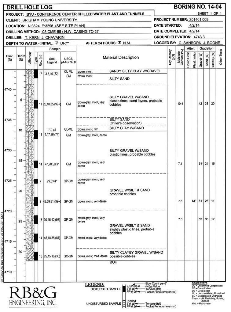
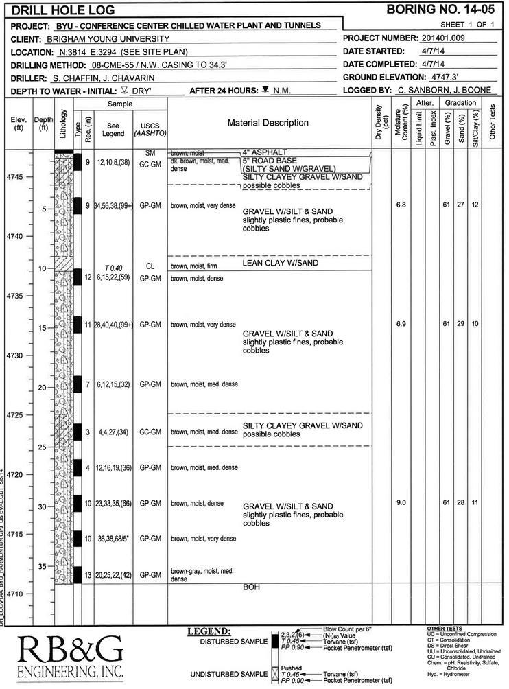
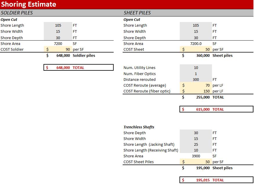
8 SHORING DESIGN A geotechnical report of the location was obtained (see Appendix B). The report revealed that the soil is predominantly gravel with silt and sand. It also showed that the water table was at least 35 feet below the surface. Since the excavation depth is only 30 feet, pumping would not be an issue during excavation. The two major options explored for deep shoring design were sheet piles and soldier piles. Sheet piles are common since they are cheap, minimize seepage, and eliminate potential caving or local shear failure. After consultation with geotechnical engineers it seemed that sheet piles were not a practical option unless the utility corridor beneath the roadway was rerouted. Calculations yielded a required section modulus of 2.3 in 3 /ft and a recommended sheet pile using US Steel PMA-22 (see Appendix C). Vibrations from installing sheet piles may be a factor to sensitive neighbors in the nearby neighborhood. Soldier piles were also considered in this design. The major advantages of soldier piles and lagging walls is versatility. Calculations showed that the apparent pressure for the design of braced excavation is 744 psf (see Appendix C). The tie backs would be spaced 8 feet vertically and 8 feet horizontally with 3 inch thick lagging. The expected moment (assuming good quality construction) is 38.1 kip-ft with a section modulus of 18.3 in 3. An HP 8x36 steel pile is recommended. Again, the utilities must be rerouted. Since sheet piles are typically cheaper than soldier piles, it is recommended that sheet piles be used in the deep shoring. TUNNEL DESIGN Two main methods for installing a concrete tunnel exist: cast-in-place and precast. The advantage of the cast-in-place method is fewer construction joints from monolithic construction. It is also easier to pour around and avoid utilities. The limiting factor for cast-in-place concrete is time. Seven days of cure time is required before the next stage can be poured to completion. In addition, the concrete can only be buried and loaded after a 28-day cure period in which the sections will gain 90% of their strength. This method would significantly extend the time for tunnel placement. It is estimated that a minimum of two pours per half of road and one 28-day cure period. Pouring PAGE 4
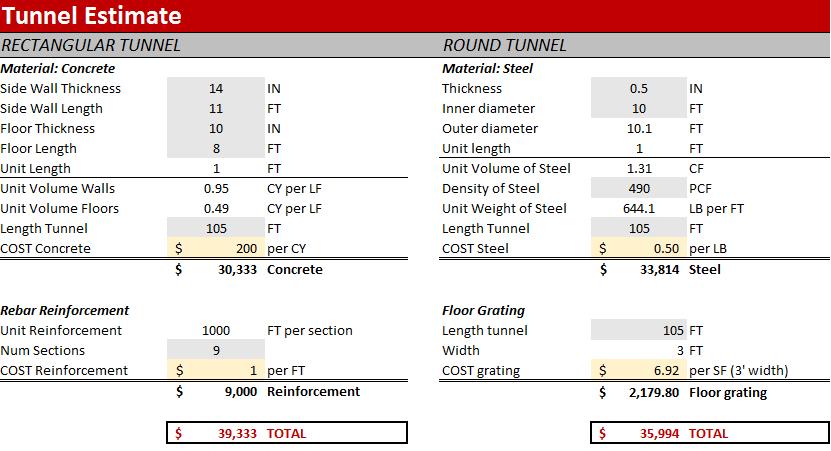
9 half of the tunnel would take approximately five weeks minimum. Since the project must be completed in six weeks, cast-in-place is not a feasible option. Instead, precast tunnel sections would be made off-site and then transported to the construction site when ready to install. Precast concrete tunnel sections would allow for the concrete to achieve cure strength off-site prior to construction. This method will reduce on-site construction time for the tunnel itself. One of the disadvantages of using a precast tunnel is waterproofing. Since there are more construction joints, more waterproofing would be required. Although the tunnel is above the water table, it is still necessary to ensure there will be no transmission of fluids in or out of the tunnel. Another disadvantage is the need for crane equipment to be on-site installing these precast sections. In most cases this is not a problem, but due to the placement of existing overhead power and phone lines it becomes more difficult and dangerous to workers. Figure 3 is a CAD drawing showing the rectangular precast tunnel design proposed for this alternative method of tunnel construction. This tunnel design measures 8-2 tall and 11 wide. Similar dimensions are shown by actual tunnel drawings in Appendix D. Nine sections at 12 feet each will total a tunnel length of 108 ft from the junction box connection. The vertical load on the tunnel is 45 kip-ft with a lateral earth pressure of 362 kip-ft. It was determined that the concrete sidewalls would be 18 inches thick and the ceiling and floor would be 11 inches thick. The precast sections would also be reinforced with steel rebar. This would be accomplished by #6 rebar framing around the perimeter of the structure tied into a grid with longitudinal bars running the length of each section. A 3-D representation of the rebar plan can be seen in Figure 4. The calculations used to determine these design values for the precast sections are shown in Appendix E. PAGE 5

10 Figure 3: Cross sectional CAD drawing of precast concrete tunnel sections Figure 4: CAD drawing of rebar plan for precast reinforced sections PAGE 6

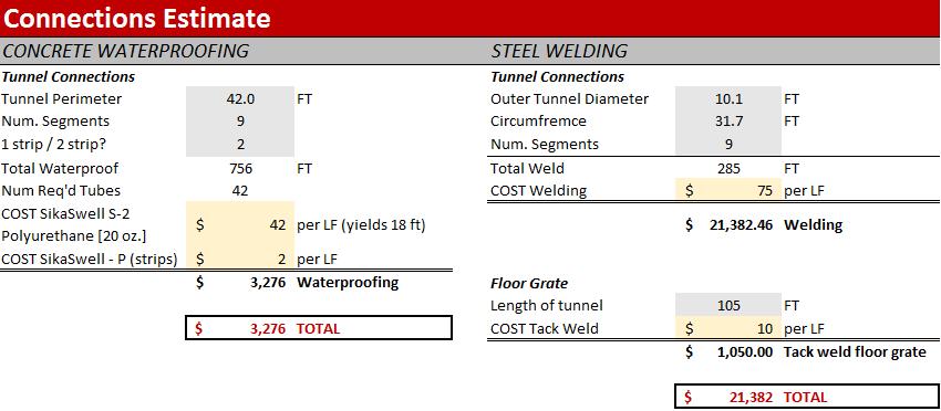
11 WATERPROOFING Many common waterproofing solutions are available. If precast tunnel sections are used, sealant at the construction joints will be needed. Each technique is similar in principle but differs in execution and performance. The simplest solution for most projects is application of sealant on the outside and inside portion of the construction joints. Possible candidates to waterproof the joints are Koster and SikaSwell. After researching, the SikaSwell joint sealant best fits project requirements. A strip swells towards water exposure and will grow to fill cracks and void spaces. It is attached using a rubber sealant that is also waterproof. TRAFFIC CONTROL Traffic control will also be an important aspect of the project. After consulting a traffic engineer, it was determined that the traffic flow during construction will be at capacity regardless of signal phasing or attempts to minimize delays. Signal timing will remain unchanged during construction. It is likely that after the initial construction begins, volume will decrease as drivers avoid the area. Since one lane must remain open in each direction during construction, preliminary sketches were drawn to illustrate the movement of traffic during the project. Figure 5 shows the path of traffic flow during one phase. For each phase, half of University Parkway will be closed for excavation and tunnel placement. After road repair is complete, the process will be repeated for the other side. Traffic cones will most likely be the easiest way to direct traffic since the project is to be completed quickly and detours are temporary. Adequate warning signs and TCDs will ensure clear and safe traffic guidance. Also since there are two left-turn bays on the northern approach of 900 E at the intersection, one will be closed since only one westbound lane will be open on 1700 N. Figure 5: Sketch representing traffic cones and the flow of traffic during each phase of construction PAGE 7
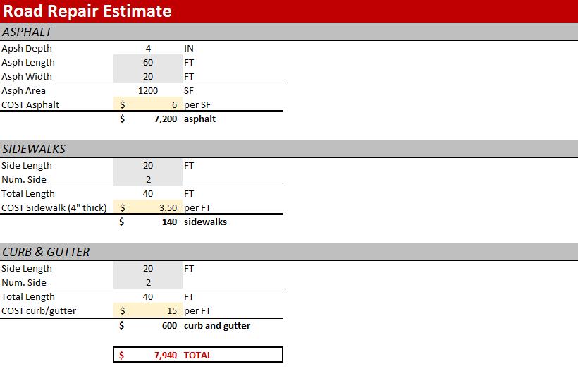
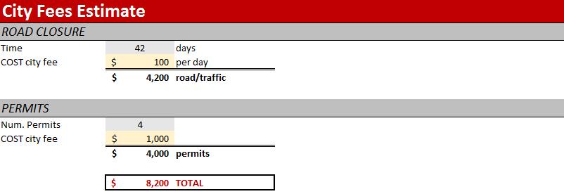
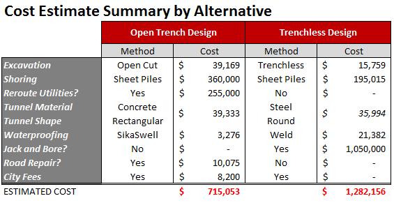
12 ROAD REPAIR After the tunnel has been placed, the trench will be backfilled and compacted. Repairs to the existing asphalt, sidewalks, and curb and gutter will need to be done to finish the project. There will be approximately 1,500 ft 2 of asphalt replaced that will be 4 inches thick. Dimensions of base material and pavement width will match current conditions. Additionally, 50 linear feet of both sidewalk as well as curb and gutter will also need to be replaced. Tests will be conducted on each product to ensure they meet the standards specified by Provo City engineers. IMPACT There is high impact with this approach since the utility corridor would need to be rerouted during construction. This may add substantial delays to construction. Also traffic delays would be significant. An open trench may pose danger to pedestrians. Construction zones will be fenced off and sound barriers used to reduce construction noise in nearby neighborhoods. All excavation will be performed in accordance with Provo City ordinances. Vibrations from installing sheet piles may be a factor to sensitive neighbors in the nearby neighborhood. A couple of matured trees will also need to be removed, which may cause some environmental concerns. Since the expansion area directly north of the road crossing is expected to be clear, a crane could be set up and operated from that lot. The overhead power lines may be able to operate despite power lines. Otherwise, they need to be rerouted so that tunnel sections can be easily lifted into place in a safe manner. Permits would need to be obtained and associating fees paid to the Provo City Engineering Department. These fees would be minimal in contrast to the project estimates. Attempts were made to get pricing from the permit department but requests were not filled. Considering costs of excavation of 1750 yd 3 of soil, rerouting of ten or more utility lines, deep shoring using sheet piles, 8 x11 precast concrete tunnel sections, SikaSwell waterproofing of joints, city fees for shutting down lanes of traffic, and road repair, Byron & Associates estimates that the total cost of this approach to be just over $715,000 (see Appendix F). PAGE 8
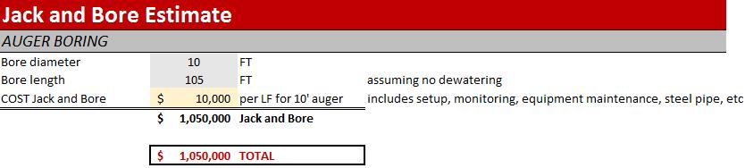
13 TRENCHLESS JACK AND BORE DESIGN JACK AND BORE Since the utility corridor was a major concern for excavation and shoring, another approach was explored. A professor referred us to a consultant who specializes in trenchless technologies. Auger boring, often referred to as jack and bore, is a popular type of horizontal boring. An illustration of the jack and bore operation is shown in Figure 6. Figure 6: Jack and bore tunneling operation The jack and bore procedure involves excavating two shafts, one on each side of University Parkway. One shaft, called the jacking pit, would contain the jacking machine and the other, known as the receiving pit, would be for removing the boring cutter head. The excavation for the jacking pit would be 25 feet long by 15 feet wide and would reach the designated depth of 30 feet. This would allow for the machine and ample room to insert each tunnel section. Shoring could be performed using sheet piles. Once the jacking machine is installed in the pit, the main jacks are retracted and steel tunnel sections are lowered into the pit. A helical auger 10' in diameter fit inside the pipe with a cutting head on the front of the leading section. As the jacks thrust the tunnel through the soil, the auger simultaneously removes spoil back to the jacking pit where it can be removed. Next, the jacks are retracted again and the next tunnel section is lowered into place. The two sections are welded together to provide waterproofing for the tunnel. The process is repeated until the tunnel reaches the receiving pit. The receiving pit would only need to be 10 feet long by 15 feet wide. The cutting head is removed and lifted out of the receiving pit and the auger is backed PAGE 9
14 out and removed. Finally, with the tunnel in place, utilities needed for the MTC expansion area are ready to be installed. TUNNEL DESIGN It was determined that the design of this tunnel will include 10 ft inner diameter steel tunnel, since the maximum size auger for jack and bore is 10 feet and is circular in shape. Although not specified in the RFP, the circular design may be advantageous because of the structural strength that a circle provides in dissipating loads. The steel tunnel was determined to be 1/2 inch thick. This would provide adequate strength to support the load above the utility tunnel. After the tunnel is in place, grating will be installed through the entire tunnel to provide for foot access and maintenance in the tunnel. The grating will be attached through tack welding. According to the cost estimate, the steel tunnel would also be cheaper than the reinforced concrete (see Appendix F). A cross-section of the design is shown in Figure 7. A 3D rendering is shown in Figure 8. PAGE 10

15 Figure 7: Cross sectional CAD drawing of steel tunnel sections Figure 8: 3D rendering of steel tunnel design. PAGE 11
16 IMPACT The trenchless design approach minimizes impact compared to the open trench design. The major advantage is reduced construction time. Since the project has time restrictions, the ability to expedite the process is valuable. The existing utilities would not need to be rerouted and road repair is unnecessary. It is estimated that construction could be completed within 4 weeks. The impacts on the surrounding neighborhood would be significantly less since there would be less excavation without an open trench across the roadway. Also, traffic flow would be able to continue undisrupted. There is some risk for settlement and raveling on the front end of the tunnel as it is being thrust through the soil. Based on the soil type, there is low risk. Equipment would carefully monitor settlement of the soil and road during the jack and bore process. It is possible that one to two inches of settlement may occur due to raveling, but this is negligible and would not affect the road. Overall, there are fewer components that could lead to problems and delays. It is a specialized but streamlined process. Considering costs of excavation of 583 yd 3 of soil for two pits, shoring using sheet piles, 10' steel tunnel sections, welding of joints, jack and bore set up and monitoring, Byron & Associates estimates that the total cost of this approach to be just under $1.3 million (see Appendix F). PAGE 12
17 CONCLUSION In summary, to provide utility services across University Parkway, several tunnel design alternatives are available to the client. Each design type has quantifiable advantages and disadvantages. Listed in this document are two design paths: an open trench and a trenchless design. Within the trenchless design, two subcategories exist. The first is a poured in place concrete tunnel. The second is a precast tunnel with twelve foot sections spanning the width of the road. In the designs proposed for this project, Byron & Associates has considered and fulfilled all RFP design requirements. The plans and cost estimations provided in this report represent the best effort of Byron & Associates to provide a safe and cost effective design. All deliverables were completed and submitted by the required deadlines, as outlined in the contractual terms and conditions. The deliverables were defined in the RFP and included tunnel design, shoring design, road repair design, and evaluation of social/environmental factors. Based on the project limitations and research performed by Byron &Associates, we ultimately recommend the trenchless jack and bore tunnel design. This method is recommended because of the time constraints for the project, the ability to avoid existing utilities and the minimal impact on the surrounding area. Although the cost for the trenchless design is greater, the benefits seem to outweigh the cost. PAGE 13
18 APPENDIX A: Topography of Project Location PAGE 14

19 APPENDIX B: Geotechnical Report PAGE 15
20 PAGE 16
21 PAGE 17
22 PAGE 18
23 APPENDIX C: Shoring Calculations Soldier Piles - The apparent pressure for design of the braced excavation is 744 psf. An average soil unit weight (γ) of 135 pcf was assumed from the geotechnical report. Since the soil type is predominantly gravel with silt and sand, a friction angle (φ) of 34 o was also assumed. K a = tan 2 (45 φ 2 ) = tan2 ( ) = P = 0.65 K a γ H = 0.65(0.283)(135 pcf)(30 feet) = 744 psf psf - The tie backs are to be spaced 8 feet vertically and 8 feet horizontally. TB1 TB2 TB Using a tributary approach, all tie backs have the same load (F). F = (8 ft)(8 ft)(744 psf) = lb = 47.6 kip Typically, a factor of safety between 1.33 and 1.5 is used in designing the tie back length. This relatively low value can be used because each anchor is proof loaded during construction. Design tie back force for 1.33(47.6 kip) 64 kips - The required tie back lengths: Tie Back Depth (ft) Length (ft) PAGE 19
24 - The expected moment (assuming good quality construction) is 38.1 kip-ft with section modulus of 18.3 in 3. (An allowable tensile stress of 25,000 psi was assumed.) (744 psf)(8 ft)(8 ft)2 M max = = 38.1 kip ft 10 S x = M max (38.1 kip ft)(12 in/ft) = = 18.3 in 3 >> Use steel pile HP 8x36 (S x = 29.8 in 3 ) f s 25 ksi - Lagging requirement: For 8 ft c-c spacing (2.44 m), use 3 inch thick lagging based on FHWA RD (1976). - Expected settlement and wall movement is 1.1 inches and 1.6 inches, respectively. Based on O Rourke (1992): (δ V ) max = H = 0.002(30ft)(12 in/ft) = 1.1 inches at wall face Settlement varies linearly with distance from wall face to a value of zero at 100 ft from wall. (δ H ) max = 1.5 (δ V ) max = 1.5 (1.08) = 1.6 in Sheet Piles - Required section modulus is 2.3 in 3 /ft. M max = 38.1 kip-ft for 8 ft spacing of soldier piles M max = S x = M max f s 38.1 kip ft = 8 (57.2 kip in) = 4.76 kip ft = 57.2 kip in for sheet pile 25 ksi = 2.3 in 3 /ft of wall Possible sheet piles would include: US Steel: PMA-22 (S x = 5.4 in 3 /ft) Canadian Rolling Mills: L34 (S x = 2.77 in 3 /ft) Arbed: BU6 (S x = 11.2 in 3 /ft) PAGE 20

25 APPENDIX D: Tunnel Drawings PAGE 21
26 APPENDIX E: Tunnel Calculations PAGE 22
27 PAGE 23
28 PAGE 24
29 PAGE 25
30 PAGE 26

31 APPENDIX F: Cost Estimation PAGE 27
32 PAGE 28
33 PAGE 29
34 PAGE 30
Pump Station Excavation
 Pump Station Excavation SPONSORED BY THE KIEWIT CORPORATION A capstone project for the The Department of Civil & Environmental Engineering in The Ira A. Fulton College of Engineering and Technology Brigham
Misan University - College of Engineering Civil Engineering Department
 CHAPTER 2 Soil and Excavations Soil investigation including two phases: surface investigation and subsurface investigation Surface investigation involves making a preliminary judgment about the site s
6 Preliminary Assessment of Construction Method and Constructability Issues
 6 Preliminary Assessment of Construction Method and Constructability Issues 6.1 Construction Approach Appendix C includes conceptual designs of the alternatives discussed below. Generally, the conceptual
BACKGROUND: SUBSURFACE CONDITIONS:
 2 BACKGROUND: The planned project consists of a prefabricated modular apartment building with underground parking, located on the site bounded by Dexter Avenue N. to the east, multi-story residential/commercial
SECTION CS-2. TRENCH EXCAVATION CONSTRUCTION STANDARDS
 SECTION CS-2. TRENCH EXCAVATION CONSTRUCTION STANDARDS CS-2-01. GENERAL: Trench excavation shall conform with the City Standard Specifications. In general a trench is defined as an excavation in which
Michael R. Lockwood Construction Management National Museum of the Marine Corps Quantico, VA
 Soil Retention System Design and Analysis Executive Summary The National Museum of the Marine Corps has a unique design element that portrays an image that the building is built underground. In order to
151 First Side. Technical Assignment 2 November 16 th, William J. Buchko. AE 481w Senior Thesis The Pennsylvania State University
 November 16 th, 2007 William J. Buchko AE 481w Senior Thesis The Pennsylvania State University Thesis Advisor: Kevin Parfitt Table of Contents Executive Summary... 3 Structural System Overview Foundation...
Section G1. Design of Cast-In-Place Box Conduits
 G1-1 Economy of Design 1. Height to Width Ratio Section G1 Design of Cast-In-Place Box Conduits Careful economic studies should be made to determine the greatest economy of the entire storm drain. As an
SECTION 39 - MANHOLES TABLE OF CONTENTS
 Section SECTION 39 - MANHOLES TABLE OF CONTENTS Page 39-1 GENERAL... 39.1 39-2 CONCRETE MANHOLES... 39.1 39-2.01 NOT USED... 39.1 39-2.02 Concrete Storm Drain Manholes... 39.1 39-3 SADDLE SEWER MANHOLES...
Ground Freezing for Tunnel, Shafts, and Adits
 Ground Freezing for Tunnel, Shafts, and Adits Joseph A. Sopko, Adam Curry Moretrench American Corporation Bianca Messina Skanska USA Civil Stephen Njoloma McMillen Jacobs Associates ABSTRACT Construction
Client Project Job # Wall Loc. SBWall Report deg 120 pcf 950 psf deg 0.0 ft. 6.0 ft 6.0 ft 2.0 ft. W16x50.
 SBWall Report Soils Data Soil Friction Angle, phi Soil Unit Weight, gamma Soil Surcharge (uniform), qs Passive Resistance, FSp Passive Wedge Width, PW*B Backfill Slope Angle, beta Ignore Passive Resistance,
Assalamualaikum & Good Morning (May All Of You Gain A Better Understanding)
") Assalamualaikum & Good Morning (May All Of You Gain A Better Understanding) Always Try To Do The Best In Your Life TYPES OF FOUNDATION TYPES OF FOUNDATION a) Shallow Foundation System i) Spread Foundation
Assalamualaikum & Good Morning (May All Of You Gain A Better Understanding) Always Try To Do The Best In Your Life TYPES OF FOUNDATION TYPES OF FOUNDATION a) Shallow Foundation System i) Spread Foundation
Chapter 3: Permit Procedures and Requirements
 Chapter 1: General Provisions 1 1 Short Title 1 2 Jurisdiction 1 3 Amendments and Revisions 1 4 Enforcement Responsibility 1 5 Review Process 1 6 Prior Approval 1 7 Relationship to Other Standards 1 8
CHAPTER 3 EXCAVATIONS
 7-3-1 7-3-1 CHAPTER 3 EXCAVATIONS SECTION: 7-3-1: Permit Requirements 7-3-2: Bond Required 7-3-3: Subject and Excluded Excavations 7-3-4: Standards 7-3-5: Protection of Public 7-3-6: Relocation and Protection
Crossroads at Westfields Building II
 Crossroads at Westfields Building II Chantilly, Va STEPHEN LUMPP Structural option Faculty Consultant: Dr. Andres Lepage Technical Report 2 EXECUTIVE SUMMARY This report is a study of alternate floor systems
SPECIAL CONDITIONS FOR HORIZONTAL AUGER BORING (HAB) October, 2006
 October, 2006") Michigan Department Of Transportation 3703B (11/06) 1 Materials SPECIAL CONDITIONS FOR HORIZONTAL AUGER BORING (HAB) October, 2006 Page 1 of 5 1.1 Pipe - Pipe used in this method includes an external steel
Michigan Department Of Transportation 3703B (11/06) 1 Materials SPECIAL CONDITIONS FOR HORIZONTAL AUGER BORING (HAB) October, 2006 Page 1 of 5 1.1 Pipe - Pipe used in this method includes an external steel
de-construction of Old City Hall
 de-construction of Old City Hall for the CITY OF GREEN COVE SPRINGS, FL 229 Walnut Street Green Cove Springs, Florida LOCATION MAP Sheet List Table T-1 COVER SHEET TEMPORARY FENCE PLAN LEGEND: GRAPHIC
ITEM 481 MONOLITHIC REINFORCED CONCRETE BOX SEWERS
 AFTER FEBRUARY 1, 2011 ITEM 481 MONOLITHIC REINFORCED CONCRETE BOX SEWERS 481.1 Description. This specification shall govern for the construction of monolithic, reinforced concrete box sewers of the size,
Technical Report #2. Matthew R Peyton
 Technical Report #2 This Document is Technical Report #2 for 5th year senior thesis in the Architectural Engineering Departments at The Pennsylvania State University. This Report is to prepare a study
CONCRETE TECHNOLOGY CORPORATION
 PRECAST, PRESTRESSED HOLLOW CORE SLABS DESIGN CRITERIA & SPAN-LOAD CHARTS FOR STORM WATER DETENTION VAULT LIDS (CHARTS REVISED /18/08) Introduction Design Criteria for Development of the Span-Load Charts
16. Design of Pipeline Structures.
 16. Design of Pipeline Structures. a. General. 1) The following guidelines are for the design of structures for water and sewer pipelines including structural concrete and miscellaneous metals design.
ITEM 430 CONSTRUCTION OF UNDERGROUND UTILITIES
 AFTER MARCH 1, 2012 ITEM 430 CONSTRUCTION OF UNDERGROUND UTILITIES 430.1 Description. This item shall govern for all excavation required for the construction of sewers, sewer structures, pipe culverts,
An Introduction to. By Michael L. Schumaker, P.E. An Introduction to Shaner Industries Metal Foundation System
 An Introduction to Metal Foundation System By Michael L. Schumaker, P.E. Introduction Various types of deep foundations are routinely used to support structures. Selection of the appropriate type of deep
APPENDIX I. Conceptual Design - Salem Road and McKay Road Trunk Watermain and Sanitary Sewer
 APPENDIX I Conceptual Design - Salem Road and McKay Road Trunk Watermain and Sanitary Sewer THE CITY OF BARRIE PROJECT NO. 15M-00594-01 CONCEPTUAL DESIGN SALEM ROAD AND MCKAY ROAD TRUNK WATERMAIN AND SANITARY
Fleet Elementary School
 Fleet Elementary School Community Newsletter () This is the February update on the status and progress of construction for the project. All monthly updates will also be posted to the project website and
UNDERGROUND UTILITY CONTRACTORS GENERAL TRADE KNOWLEDGE EXAMINATION CONTENT INFORMATION
 UNDERGROUND UTILITY CONTRACTORS GENERAL TRADE KNOWLEDGE EXAMINATION CONTENT INFORMATION Effective September 9, 2014 The General Trade Knowledge portion of the examination is administered daily in Computer
SECTION 39 - MANHOLES TABLE OF CONTENTS 39-1 GENERAL PRECAST CONCRETE MANHOLES
 Section SECTION 39 - MANHOLES TABLE OF CONTENTS 39-1 GENERAL... 39-1 39-2 PRECAST CONCRETE MANHOLES... 39-1 39-2.01 Precast Concrete Storm Drain Manholes... 39-1 39-3 SADDLE MANHOLES... 39-2 39-3.01 Saddle
Design Data 4. Jacking Concrete Pipe
 Design Data 4 Jacking Concrete Pipe FOREWORD Jacking or tunneling concrete pipe is an increasingly important construction method for installing concrete pipelines without interrupting commerce, or disturbing
Caitlin Ferrell Structural Option Dr. Boothby, AE Faculty Consultant. Erie Convention Center and Sheraton Hotel
 Caitlin Ferrell Structural Option Dr. Boothby, AE Faculty Consultant Erie Convention Center and Sheraton Hotel Erie, Pennsylvania Technical Report #2: Pro-Con Structural Study of Alternate Floor Systems
SECTION BORING AND/OR JACKING PIPE
 02910-1 of 6 SECTION 02910 BORING AND/OR JACKING PIPE 02910.01 GENERAL A. Description Boring and/or jacking pipe shall include, but not necessarily be limited to, furnishing and installing carrier pipe
Department of Building and Zoning Approaches and Sidewalks for ONE AND TWO FAMILY CONSTRUCTION
 Department of Building and Zoning Approaches and Sidewalks for ONE AND TWO FAMILY CONSTRUCTION GENERAL ITEMS SUBGRADE Prior to pouring concrete all subgrades must be wetted and compacted. All formwork
DIAPHRAGM WALLS, CUT-OFF WALLS AND SLURRY WALLS
 DIAPHRAGM WALLS, CUT-OFF WALLS AND SLURRY WALLS Implenia Spezialtiefbau GmbH Robert Bosch Straße 25 D-63225 Langen Phone: +49 6103 988 345 Fax: +49 6103 988 277 Email: info.spezialtiefbau@implenia.com
TRENCHLESS CONSTRUCTION (BORING, JACKING, AND TUNNELING)
") PART 1 - GENERAL TRENCHLESS CONSTRUCTION (BORING, JACKING, AND TUNNELING) 1.01 SECTION INCLUDES A. Trenchless Installation of Carrier Pipe with Casing Pipe B. Trenchless Installation of Carrier Pipe without
PART 1 - GENERAL TRENCHLESS CONSTRUCTION (BORING, JACKING, AND TUNNELING) 1.01 SECTION INCLUDES A. Trenchless Installation of Carrier Pipe with Casing Pipe B. Trenchless Installation of Carrier Pipe without
SECTION STORM DRAINAGE
 SECTION 02720 STORM DRAINAGE PART 1 - GENERAL 1.01 WORK INCLUDED A. Trenching and other excavation. B. Ground water control. C. Pipe bedding. D. Installation of storm drains and appurtenances. E. Installation
Draft. Not Yet Approved SECTION 10.1 GENERAL SCOPE DEFINITIONS
 SECTION 10.1 GENERAL 10.1.1 SCOPE This part of the Manual covers the structural design and installation of reinforced concrete pipe for railway culverts. Pipe geometry may be circular, arch, or elliptical.
A. Section includes temporary excavation support and protection systems.
 SECTION 31 50 00 - EXCAVATION SUPPORT AND PROTECTION PART 1 - GENERAL 1.1 RELATED DOCUMENTS A. Drawings and general provisions of the Contract, including General and Supplementary Conditions and Division
SECTION TRENCHING
 SECTION 31 23 17 TRENCHING PART 1 GENERAL 1.1 SUMMARY A. Section Includes: 1. Excavating trenches for utilities and utility structures. 2. Bedding. 3. Backfilling and compacting to subgrade elevations.
Upon speaking with the representatives with Technical Foundations as well as Walder Foundations, it was determined that:
 As part of our analyses, we have considered the design and construction of the cantilever retaining wall that will be located along the north side of Lucks Lane, between Falling Creek and Gladstone Glen
Purple Line Extension. Beverly Hills Community Meeting August 22, 2016
 Purple Line Extension Beverly Hills Community Meeting August 22, 2016 1 3 Purple Line Extension Project Alignment 2 Section 2 and 3 Status Under Construction Forecasted Schedule Section 1 Section 2 Section
HORROCKS. Engineering Review of Proposed Cast-in-Place. Reinforced Arch Culvert Specification. For. Rinker Material Concrete Pipe Division
 JO7 For Engineering Review of Proposed Cast-in-Place SPECS Item #6 December 12, 2018 Handout Date: December11, 201$ Prepared By: PLK Reviewed By: DAA HORROCKS PROJECT NO. 18001 Phase 27 Rinker Material
CITY OF WILSON. Public Services Engineering. Backfilling, Compaction, & Patching Policy on Existing Pavements
 CITY OF WILSON Public Services Engineering Backfilling, Compaction, & Patching Policy on Existing Pavements INTRODUCTION The City of Wilson recognizes that proper backfilling, compaction, and patching
Detailed Estimating-Introduction. Dr. Al-Hammad
 Detailed Estimating-Introduction By Dr. Al-Hammad Outline Introduction Successful Construction Estimating The Detailed Estimating Procedure The stretch - out - Length concept (SOL) Site Work and Excavation
Eglinton Crosstown LRT Construction Liaison Committee
 Eglinton Crosstown LRT Construction Liaison Committee May 30, 2017 Agenda Eglinton Crosstown LRT Overview Eglinton Maintenance & Storage Facility Mount Dennis Station Railway Corridor West Portal & Elevated
H. Underground Transmission System Design
 H. Underground Transmission System Design In addition to analyzing potential routes, the Company considered several different design technologies for the proposed underground transmission supply lines,
Hamilton Rapid Transit Preliminary Design and Feasibility Study
 Hamilton Rapid Transit Preliminary Design and Feasibility Study B-LINE STRUCTURAL ASSESSMENT DESIGN BRIEF Version:1.0 Hamilton Rapid Transit Preliminary Design and Feasibility Study B-LINE STRUCTURAL ASSESSMENT
Temecula Medical Center Temecula, CA
 Temecula Medical Center Temecula, CA Technical Assignment #2 Sean F. Beville The Pennsylvania State University Architectural Engineering Structural Option Senior Thesis Project Student Advisor: Thomas
VARIOUS TYPES OF SLABS
 VARIOUS TYPES OF SLABS 1 CHOICE OF TYPE OF SLAB FLOOR The choice of type of slab for a particular floor depends on many factors. Economy of construction is obviously an important consideration, but this
Investigation for the Removal of Steel Tie Rods in a Historic Segmental Arch Floor
 Investigation for the Removal of Steel Tie Rods in a Historic Segmental Arch Floor J. Lan 1, R. Gilsanz 2, and M. Lo 3 1 Gilsanz Murray Steficek, LLP, 129 West 27 th St., 5 th Floor, New York, NY 10001
ST. TAMMANY PARISH PATRICIA P. BRISTER PARISH PRESIDENT
 ST. TAMMANY PARISH PATRICIA P. BRISTER PARISH PRESIDENT August 7, 2018 Please find the following addendum to the below mentioned BID. Addendum No.: 1 Bid#: 314-00-18-38-2 Project Name: Johnny F. Smith
BASEMENT CONSTRUCTION PREPARED BY PN NOOR AISYAH ASYIKIN
 BASEMENT CONSTRUCTION PREPARED BY PN NOOR AISYAH ASYIKIN BASEMENT CONSTRUCTION 01 content 1.DEFINITION 2. CONSTRUCTION CONSIDERATION 3. DESIGN REQUIREMENT 4.METHOD OF CONSTRUCTION a. Open Cut Construction
JANUARY 25, 2016 ADDENDUM NO. 3 FOR. ORD Baggage Service Road Retaining Wall Repair
 JANUARY 25, 2016 ADDENDUM NO. 3 FOR ORD Baggage Service Road Retaining Wall Repair Specifications and Contract Documents Number: 132110 CDA Project Number: H6163.15-02 For which bids are scheduled to be
Construction Technology B (CON4313)
") 3 - Basement 1 Quick Revision 1.1 Problems arising from basement construction a. Excavation method. b. Surface and ground water control c. Lateral stability of basement excavation. d. Stability of adjoining
3 - Basement 1 Quick Revision 1.1 Problems arising from basement construction a. Excavation method. b. Surface and ground water control c. Lateral stability of basement excavation. d. Stability of adjoining
Earth Retention Systems
 haywardbaker.com Earth Retention Systems Mark W. Goodsell, P.E., D.GE Senior Engineer 2 Earth Retention Systems Focus of Presentation Different Types and Purposes of Earth Retention Systems Design Considerations/Geotechnical
ROAD CUT PERMIT APPLICATION & INSTRUCTIONS
 Jeremy Robinson Commissioner Ann Fordock Martin E. Davis, L.S. DEPARTMENT OF PUBLIC WORKS Ben Walsh, Mayor ROAD CUT PERMIT APPLICATION & INSTRUCTIONS REQUIRED FOR: Construction in (cutting into) a city
Office Building-G. Thesis Proposal. Carl Hubben. Structural Option. Advisor: Dr. Ali Memari
 Office Building-G Thesis Proposal Structural Option December 10, 2010 Table of Contents Executive Summary... 3 Introduction... 4 Gravity System...4 Lateral System:...6 Foundation System:...6 Problem Statement...
Civil Engineering Construction I (CBE5031)
") Civil Engineering Construction I (CBE5031) Basement 1 1 Quick Revision 1.1 Problems arising from basement construction a) Excavation method. b) Surface and ground water control c) Lateral stability of
Civil Engineering Construction I (CBE5031) Basement 1 1 Quick Revision 1.1 Problems arising from basement construction a) Excavation method. b) Surface and ground water control c) Lateral stability of
1993 Specifications CSJ'S & SPECIAL SPECIFICATION ITEM Tree Preservation and Treatment
 1993 Specifications CSJ'S 0912-71-554 & 0912-71-555 SPECIAL SPECIFICATION ITEM 1016 Tree Preservation and Treatment 1. Description. This section specifies the requirements for protecting trees and related
SPECIAL PROVISIONS - SP2014 BOOK Page 1 October 8, 2013
 SPECIAL PROVISIONS - SP2014 BOOK Page 1 S-1 (2104) REMOVE AND REPLACE BITUMINOUS PAVEMENT (ADA) Always include SP2014-119 (PLANT MIXED ASPHALT PAVEMENT) or SP2014-121 (PLANT MIXED ASPHALT PAVEMENT FOR
Albany Park Stormwater Diversion Tunnel
 Albany Park Stormwater Diversion Tunnel Frequently Asked Questions The Basics Who, What, When, Where, Why, How Why is the project being performed? The project is being constructed to reduce flooding in
Albany Park Stormwater Diversion Tunnel
 Albany Park Stormwater Diversion Tunnel Why is the project being performed? Frequently Asked Questions The Basics Who, What, When, Where, Why, How The project is being constructed to reduce flooding in
SECTION SITE PREPARATION. A. PART A and DIVISION 1 of PART B are hereby made a part of this SECTION.
 SECTION 311000 PART 1 GENERAL 1.01 GENERAL REQUIREMENTS A. PART A and DIVISION 1 of PART B are hereby made a part of this SECTION. B. Examine all conditions as they exist at the project prior to submitting
OVERALL STRUCTURAL SYSTEM
 EXECUTIVE SUMMARY The at the Pittsburgh International Airport, PA, is a 275,000 square foot multi-use building located directly adjacent to the airport s landside terminal. The building consists of an
STANDARDIZED STRUCTURES
 Q, QH & QL TOWERS 16.1 Q, QH, and QL Towers General Description The series includes three and four leg angle towers, which are suited for a variety of antenna mounting positions and load conditions. The
1. All underground utilities under railroad tracks shall be encased in a larger pipe or conduit called the casing pipe.
 MTS Jack and Bore Design Criteria Note: For the purposes of this Design Criteria and subsequent Construction Notes, the term Jack and Bore is used generically to refer to a number of trenchless construction
Project. San Jose City College Physical Education Building. Prepared For. Prepared By PLACE IMAGE HERE. Ken Bauer, AIA Principal
 Project San Jose City College Physical Education Building PLACE IMAGE HERE Prepared For Ken Bauer, AIA Principal LPAS 2484 Natomas Park Drive Sacramento, CA 95833 916.443.0335 Prepared By Steve Ratchye,
EXCAVATION WORK IN PUBLIC RIGHT-OF-WAY GENERAL NOTES
 CITY OF SANTA MONICA Department of Public Works Civil Engineering Division 1685 Main, Room 116 Santa Monica, CA 90401 Tel: (310) 458-2240 or (310) 458-8737 EXCAVATION WORK IN PUBLIC RIGHT-OF-WAY GENERAL
SECTION 19 - TRENCH EXCAVATION, BEDDING AND BACKFILL TABLE OF CONTENTS
 SECTION 19 - TRENCH EXCAVATION, BEDDING AND BACKFILL TABLE OF CONTENTS Section Page 19-1 TRENCH EXCAVATION... 19.1 19-1.01 Exploratory Excavation... 19.1 19-1.02 Trench Width... 19.1 19-1.02.A Storm Drain
Structural Design of Dam Sluice Gate Walkway Slabs: Retrofit and Replacement Options
 Structural Design of Dam Sluice Gate Walkway Slabs: Retrofit and Replacement Options A local utility company issued a Request for Proposal to our university s capstone design class for structural improvements
Table of Contents. July
 Table of Contents 36.1 General... 3 36.1.1 Bridge or Culvert... 3 36.1.2 Box Culvert Size Restrictions... 4 36.1.3 Stage Construction for Box Culverts... 4 36.2 Dead Loads and Earth Pressure... 5 36.3
TRENCHLESS CONSTRUCTION (BORING, JACKING, AND TUNNELING)
") PART 1 - GENERAL TRENCHLESS CONSTRUCTION (BORING, JACKING, AND TUNNELING) 1.01 SECTION INCLUDES A. Trenchless Installation of Carrier Pipe with Casing Pipe B. Trenchless Installation of Carrier Pipe without
PART 1 - GENERAL TRENCHLESS CONSTRUCTION (BORING, JACKING, AND TUNNELING) 1.01 SECTION INCLUDES A. Trenchless Installation of Carrier Pipe with Casing Pipe B. Trenchless Installation of Carrier Pipe without
(D) Surface Slope Bituminous patch in front of the truncated domes must not exceed 5% measured perpendicular to the flow line or edge of roadway.
 Surface Slope Bituminous patch in front of the truncated domes must not exceed 5% measured perpendicular to the flow line or edge of roadway.") Last Revision by CO Special Provisions: 09/14/18 Page 1 S-1 (2104) REMOVE AND REPLACE BITUMINOUS PAVEMENT (ADA) Always include SP2018-143 ((2360) PLANT MIXED ASPHALT PAVEMENT (MSCR)) when using this writeup.
Last Revision by CO Special Provisions: 09/14/18 Page 1 S-1 (2104) REMOVE AND REPLACE BITUMINOUS PAVEMENT (ADA) Always include SP2018-143 ((2360) PLANT MIXED ASPHALT PAVEMENT (MSCR)) when using this writeup.
SPECIAL CONDITIONS FOR PIPE JACKING (PJ) October, 2006
 October, 2006") Michigan Department Of Transportation 3703C (11/06) 1 Materials 1.1 Pipe SPECIAL CONDITIONS FOR PIPE JACKING (PJ) October, 2006 Page 1 of 5 The type of pipe used for the pipe jacking method shall be capable
Michigan Department Of Transportation 3703C (11/06) 1 Materials 1.1 Pipe SPECIAL CONDITIONS FOR PIPE JACKING (PJ) October, 2006 Page 1 of 5 The type of pipe used for the pipe jacking method shall be capable
SPECIAL CONDITIONS FOR MICROTUNNELING (MT) October, 2006
 October, 2006") Michigan Department Of Transportation 3703F (11/06) SPECIAL CONDITIONS FOR MICROTUNNELING (MT) October, 2006 Page 1 of 5 1 Materials 1.1 Pipe (a) Pipe shall be specifically designed and certified for microtunneling
Michigan Department Of Transportation 3703F (11/06) SPECIAL CONDITIONS FOR MICROTUNNELING (MT) October, 2006 Page 1 of 5 1 Materials 1.1 Pipe (a) Pipe shall be specifically designed and certified for microtunneling
SECTION UTILITY POLYETHYLENE CONTAINMENT PIPE SYSTEMS
 SECTION 02670 UTILITY POLYETHYLENE CONTAINMENT PIPE SYSTEMS PART 1 - GENERAL 1.01 WORK INCLUDED A. Trenching and other excavation. B. Ground water control. C. Pipe bedding. D. Installation of containment
ITEM 432 TUNNEL CONSTRUCTION
 AFTER MARCH 1, 2012 ITEM 432 TUNNEL CONSTRUCTION 432.1 Description. This Item shall govern for tunnel lines under railroads, state highways, and concrete paved streets or other obstructions indicated.
APPENDIX B ABC STRUCTURES DESIGN GUIDE
 APPENDIX B ABC STRUCTURES DESIGN GUIDE The Cohos Evamy Partners TABLE OF CONTENTS Page No. DISCLAIMER... I 1. STRUCTURAL DESIGN GUIDELINES... 1 2. GENERAL REQUIREMENTS (FIGURE B.2, STEP 1)... 1 3. GENERAL
CHAPTER 11 - RESTORATION OF SURFACE IMPROVEMENTS
 CHAPTER 11 - RESTORATION OF SURFACE IMPROVEMENTS 11.1 GENERAL The Developer/Contractor shall be responsible for the protection and the restoration or replacement of any improvements existing on public
SECTION A1 EXCAVATION AND BACKFILL GENERAL
 SECTION A1 EXCAVATION AND BACKFILL GENERAL The work under this section shall include all excavation to such width and depth as shown on the drawings, specified herein, or ordered by the Engineer. Such
How Loads Are Distributed
 LOAD DISTRIBUTION 1 LOAD DISTRIBUTION This section illustrate how load will transmit from the deck to the stringers. Determining the fraction of load carried by a loaded member and the remainder distributed
Geotechnical Exploration and Evaluation Report
 Geotechnical Exploration and Evaluation Report Pavement Coring and Evaluation UNF Parking Lot 3 Jacksonville, Florida CSI Geo Project No.: 71-18-135-23 Prepared by CSI Geo, Inc. 2394 St. Johns Bluff Road
Section 401. PIPE CULVERTS
 401.02 Section 401. PIPE CULVERTS 401.01. Description. This work consists of constructing pipe culverts of the size and class required, including excavation and backfill. 401.02. Materials. Provide materials
ST. TAMMANY PARISH PATRICIA P. BRISTER PARISH PRESIDENT
 ST. TAMMANY PARISH PATRICIA P. BRISTER PARISH PRESIDENT April 17, 2018 Please find the following addendum to the below mentioned QUOTE. Addendum No.: 1 Quote#: 310-00-18-08-1 Project Name: Greenleaves
Construction Requirements for Installation of Utilities in the Public Right-of-way of McPherson County, Kansas October 2011
 Construction Requirements for Installation of Utilities in the Public Right-of-way of McPherson County, Kansas October 2011 General Provisions and Specifications - These provisions and specifications shall
DESIGNING AND CONSTRUCTION OF T-WALL RETAINING WALL SYSTEM
 Istanbul Bridge Conference August 11-13, 2014 Istanbul, Turkey DESIGNING AND CONSTRUCTION OF T-WALL RETAINING WALL SYSTEM T. C. NEEL and K.BOZKURT ABSTRACT This work shall consist of the design, manufacture
Jonathan R. Torch Technical Report 2 Columbia University. Technical Report 2. Pro-Con Structural Study of Alternate Floor Systems
 Technical Report 2 Pro-Con Structural Study of Alternate Floor Systems Columbia University Broadway & 120 th Street, New York, NY Jonathan R. Torch Pennsylvania State University Architectural Engineering
SECTION 14 - RESTORATION OF SURFACES TABLE OF CONTENTS
 SECTION 14 - RESTORATION OF SURFACES TABLE OF CONTENTS Section Page SECTION 14 RESTORATION OF SURFACES... 14.1 14-1 GENERAL... 14.1 14-2 PRIVATE ROADS... 14.1 14-3 STREETS AND PARKING LOTS... 14.1 14-3.01
FDA OC/ORA Office Building
 FDA OC/ORA Office Building Table of Contents Executive Summary... 3 Introduction... 4 Structural System... 5 Foundation:... 5 Floor System:... 7 Building 31:... 7 Building 32:... 9 Columns... 10 Lateral
SLIDE RAIL SHORING SYSTEMS
 SLIDE RAIL SHORING SYSTEMS THE LEADING PRODUCER & DISTRIBUTOR OF TRENCH SHIELDING & SHORING EQUIPMENT SINCE 1995 Pro-Tec Equipment Slide Rail Shoring Systems What is Pro-Tec Equipment s Slide Rail? The
DESIGN STANDARDS. Division 02 Existing Conditions- Site Work. General
 DESIGN STANDARDS Division 02 Existing Conditions- Site Work General I. This Division includes: A. Demolition B. Clearing and Grubbing C. Excavation, Backfill and Compaction D. Pavement Base E. Paving and
SECTION 19 - TRENCH EXCAVATION, BEDDING AND BACKFILL TABLE OF CONTENTS
 SECTION 19 - TRENCH EXCAVATION, BEDDING AND BACKFILL TABLE OF CONTENTS Section Page 19-1 TRENCH EXCAVATION...19.1 19-1.01 Exploratory Excavation...19.1 19-1.02 Trench Width...19.1 19-1.02.A Storm Drain
Contents. Before you begin. Introduction: Installing trench support 1. Element 1: Planning and preparing 3
 Contents Contents Before you begin v Introduction: Installing trench support 1 Element 1: Planning and preparing 3 Section 1.1 Accessing, interpreting and applying compliance documentation 4 to the work
North Mountain IMS Medical Office Building
 North Mountain IMS Medical Office Building Phoenix, Arizona Michael Hopple Technical Assignment 2 October 29 th, 2007 AE 481W-Senior Thesis The Pennsylvania State University Faculty Adviser: Dr. Ali Memari,
THE FORENSIC MEDICAL CENTER
 THE FORENSIC MEDICAL CENTER Image courtesy of Gaudreau, Inc. TECHNICAL REPORT #2 OCTOBER 26, 2007 KEENAN YOHE STRUCTURAL OPTION DR. MEMARI FACULTY ADVISOR EXECUTIVE SUMMARY Image courtesy of Gaudreau,
Stephan Northrop Structural Option Dr. Linda Hanagan. North Shore Equitable Building Pittsburgh, PA Senior Thesis Proposal
 Stephan Northrop NORTHROP THESIS PROPOSAL PAGE - 1 TABLE OF CONTENTS Executive Summary.. 3 1. Introduction.. 4 2. Structural Systems.. 5 Foundation.. 5 General Floor Framing.. 6 Turret Framing.. 7 Roof
Sweet Creek Road Retaining Wall Replacement. Mapleton, OR
 Sweet Creek Road Retaining Wall Replacement Mapleton, OR Technical Information Project Completion Date: April 30, 2013 Project Location: Mapleton, OR Size of Project: 15,000 SF, 870 CY Concrete Strength
UNDERPINNING A CRANE FOUNDATION
 UNDERPINNING A CRANE FOUNDATION Donald R. McMahon, P.E., McMahon & Mann Consulting Engineers, P.C., Buffalo, New York, USA Andrew J. Nichols, P.E., McMahon & Mann Consulting Engineers, P.C., Buffalo, New
Sabah Shawkat Cabinet of Structural Engineering 2017
 3.9 Concrete Foundations A foundation is a integral part of the structure which transfer the load of the superstructure to the soil without excessive settlement. A foundation is that member which provides
MODEL SPECIFICATIONS: Hydraulically Driven Steel Underpinning Pile Specifications
 MODEL SPECIFICATIONS: Hydraulically Driven Steel Underpinning Pile Specifications Mar/2008 v1.0 SECTION 02255 HYDRAULICLY DRIVEN STEEL UNDERPINNING PILES PART 1 GENERAL 1.01 SCOPE OF WORK The work shall
INSTALLING A POUR-IN-PLACE DOCK LEVELER (EH & RR)
") INSTALLING A POUR-IN-PLACE DOCK LEVELER (EH & RR) Part A: Prepare the Site & Make the Floor 1.) Prepare (concrete) dock wall and pit floor as shown in the diagrams. Pit floor should taper from back to
INSTALLING A POUR-IN-PLACE DOCK LEVELER (EH & RR) Part A: Prepare the Site & Make the Floor 1.) Prepare (concrete) dock wall and pit floor as shown in the diagrams. Pit floor should taper from back to
Current Standard Plates including Transmittal Letters are available on the web at:
 MINNESOTA DEPARTMENT OF TRANSPORTATION DEVELOPED BY: Design Standards ISSUED BY: Office of Project Management and Technical Support, Design Support Section TRANSMITTAL LETTER NO. (6-03) MANUAL: Standard