Document Purpose: Document Scope:
|
|
|
- Laurel Copeland
- 6 years ago
- Views:
Transcription
1 Document Purpose: Washington University School of Medicine, BJC and Telecommunications Facility Corporation Low Voltage Voice and Data Pathways and Spaces Standard July 21, 2016 The purpose of this document is to provide a planning guide for the design of low voltage pathways and space for all new facilities and major renovations. This document is based on information gleaned from best practice documentation, EIA- 568C, EIA-568B, TSB-469. It provides ongoing Voice & Data guidelines and confirms established STANDARDS that apply to any construction or maintenance of BEFs (Building Entrance Facility), Main TRs (Main Telecommunication Room), TRs (Telecommunication Room) or any other communications facilities that are the responsibility of the Telecommunications Facility Corporation (TFC), BJC Network Operations and Washington University School of Medicine (WUSM) groups as occupants. Only contractors with a current BICSI RCDD on staff and listed on the approved WUSM/BJC/TFC Communications Group s Approved Low Voltage contractor list will be allowed to bid low voltage structured wiring projects. These standards will be employed when constructing new, or modifying existing communications rooms. The standards are based on a basic rectangular shaped room of adequate dimensions. Since each instance of provided space can be unique in nature, these standards shall be adapted to the space provided when approved by the appropriate Communications group (s). Access to the BEF & TR s will unobstructed. Access will be from a hallway whenever possible. Avoid using an adjoining office or user space for access. A badge swipe for the door is the required method of access to the BEF and TR s for BJC but is the preferred method of access for WUSM. Anytime drilling is taking place in a BEF/MTR, TR or any communications facility the use of a HEPA filter is required. This document is also intended to provide standard practices for ANY installation(s) or maintenance of equipment, furnishings or wiring housed within each of these locations. Additionally, it provides installation guidelines and procedures for BJC/WUSM/TFC low voltage cabling specific to Data and Voice communications within BJC/WUSM facilities. This document is to be provided to all low voltage contractors by the specific group bidding the project. The processes and standards contained herein shall supersede any other previously dated Communications Standards documents provided for Low Voltage work unless an exception is specifically agreed upon by TFC, BJC Network Operations, and WUSM Network Operations. BJH, MBMC & SLCH Locations require proper permitting prior to installation. The Standards information contained within this document should be used in conjunction with and applied to, each project specification. Each bid request will uniquely define the scope for a particular project and the information contained herein SHOULD NOT be interpreted as an opportunity to substitute requirements or scope specific to any project. Any bidder who has not been given specific requirements & scope for a given project should contact the project manager for the project s requirements. Document Scope: The scope of this document includes physical rooms and spaces, pathways, racks, conduit systems, cable trays, raceways, and any other physical system used to support or terminate low voltage cabling systems. This document provides an overall specification of cable types, services, and termination equipment. This document should be used solely for the purposes of planning and designing the appropriate telecommunication rooms, building entrance facilities, cable tray and raceways systems, and all conduits used for low voltage voice and data. 1
2 Document Outline: Part 1: Planning and Design p. 5 Part 2: Building Entrance Facilities and Conduit Feeds p. 5 Part 3: Building Layout and Conduit Design p. 7 Part 3a: Building Layout p. 8 Part 3b: Vertical Backbone p. 9 Part 4: Telecommunications Rooms Size and Rack Layout p. 11 Part 4a: Main Telecommunication Rooms Main TR p. 11 Part 4b: Telecommunication Rooms TR p. 13 Part 4c: Oversized Telecommunication Rooms p. 16 Part 5: Cable Tray and Horizontal Pathways p. 17 Part 6: Grounding and Bonding p. 19 Article 1 Building Single Grounding Point p. 20 Article 2 Telecommunication Main Grounding Buss Bar (TMGB) p. 21 Article 3 Telecommunications Bonding Backbone (TBB) p. 21 Article 4 Telecommunication Grounding Buss Bar (TGB) p. 22 Article 5 Grounding and Bonding Building Entrance of Facilities (BEF), Main Telecommunication Rooms (MTR) and Telecommunication Rooms (TR) p. 23 Article 6 Appropriately sizing ground conductors p. 24 Article 7 Best Practices p. 24 Part 7: General Information p. 28 Part 7a: Data Equipment Racks p. 28 Part 7b: Voice Equipment Racks p. 28 Part 7c: Room Layout p. 28 Part 7d: Data Wire p. 30 Part 7e: Data Cabling p. 30 Part 7f: Voice Cabling p. 31 2
3 Part 7g: Fiber Optic Cabling p. 32 Part 7 h: Labeling: Voice/Data Fiber Trunks p. 34 Part 7i: Raceways and Cable Runs p. 36 Part 7j: Additional Information p. 37 Part 7k: Architectural Drawing Standards p. 37 Part 8: Wireless p. 40 Part 9: MOB p. 41 Part 10: POB p. 42 Part 11: COB p. 43 Part 12: Outside Plant p. 44 Part 13: Barrier and above ceiling Policies and procedures p. 45 Part 13a: BJH Barrier Integrity Policy and Procedures (BIPP) p. 45 Part 13b: BJH Barrier Access Permit Policy and Procedures (BAP) p. 52 Part 13c: SLCH Access and Above Ceiling work Policy p.58 Part 13d: MBMC Facilities Standard Practices. P. 61 Appendices: Appendix A Grounding and Bonding Terms and Abbreviations p.25 Appendix B Telecommunication Terms and Abbreviation p.25 Appendix C Building Grounding and Bonding Diagram p.26 Appendix D Telecommunication /Equipment Room Grounding and Bonding Diagram p.27 Appendix E Wall Plate Labeling Diagram p.66 Appendix F CAT5e Conduit Fill Ratio Planning Guide p.67 Appendix G CAT6 Conduit Fill Ration Planning Guide p.67 Appendix H CAT 6 Cable Tray Fill Capacity p.67 Appendix I WUSM/BJC/Main TR/ TR Power Requirements p. 69 Appendix J Elevator Voice Cable Design p.70 Appendix K Paging for Academic Sites p.71 3
4 Appendix L Contractors Standards / Code of Conduct p 74 Appendix M Copper Field Testing Requirements p 76 Appendix N Fiber Field Testing Requirements p 85 Appendix O Manufacturer Part Numbers p 94 Appendix P Changes to the Document p 98 4
5 Part 1: Planning and Design The goal of the planning and design for low voltage pathways and spaces is to ensure the current user s needs are met, the low voltage contractors have the pathway and spaces required to easily and safely install the cabling systems, to ensure the low voltage systems perform to WUSM/TFC/BJC s highest standards, and to ensure adequate growth space for new services, new workspaces, and technological change. A documentable methodology is the easiest way to ensure both Design & Construction and BJC/TFC/WUSM cover all the bases and plan ahead for all new facilities and major renovations. Part 2: Building Entrances Facilities and Conduit Feeds All Major 0 WUSM/BJC/TFC Medical Center campus facilities are designed with a primary (A) and secondary (B) conduit feed. The primary conduit feed for all major facilities (I.E. CSRB, PRB, FLTC) are run to the nearest or most cost effective TFC conduit corridor system manhole of the. The secondary feed will run either to a secondary TFC corridor system manhole using a diverse route or to an adjacent or nearby facility using a diverse indoor or outdoor route 1. Non-major buildings (I.E. 22 North Euclid, Storz, Biohazard) are designed with only a primary (A) conduit feed or may even utilize a leased circuit if it is not located on campus. Primary conduit feeds for non-major facilities may be run to the TFC corridor system, WUSM fiber, or a service provider s infrastructure. 0 Major is identified as clinical Treatment facilities or Critical Equipment Areas. 1 In most situations WUSM/BJ will utilize TFC resources for outdoor routes unless not approved by the TFC Board. 5
6 Refer to (A) and (B) in Exhibit 1a: for more details. The following decisions need to be made when planning the Building Entrance Facility (BEF)(H) and/or Main Telecommunications Room (Main TR) (H): Number of 4 conduits required for the Primary Building Conduit Feed (A) Number of 4 conduits required for the Secondary Building Conduit Feed (B) The location of the BEF and Main TR in relation to the location of the entry point of the primary and secondary conduits. The normal standard for the number of primary building conduits is 4 4 conduits. This provides 2 4 conduits to the corridor system for fiber optics and 2 4 conduits for diverse routing. Some factors to consider are: Number of fiber trunks required upfront Number of potential future feeds For buildings considered non-major, 2 4 conduits are typically sufficient 2. Refer to the location of the Main TR (H) and BEF/Main TR (H) in Exhibit 1b: below. If the Main TR (H) and BEF (H) are two separate spaces, the primary (A) and secondary (B) building conduit feeds must be run from the BEF (H) to the Main TR (H). If the BEF (H) and Main TR (H) utilize the same space, this extra length of conduit is not required but any outdoor rated cable must be terminated within 50 of entering the facility. The location of the BEF often dictates the conduit cost for a new facility. It may appear to be more cost effective to locate the BEF on an exterior wall to make the entry point simpler and reduce the amount of internal conduits. However, in most cases, if the BEF is located on the exterior of the facility, conduits may still need to be run to the Main TR or if the BEF and Main TR coexist, the vertical backbone (C) to the Telecommunication Rooms (TR) (J) may be longer and most costly if the Main TR and TRs do not stack or line up vertically. 2 In most cases, an as needed decision is made for non-major facilities. However, the cost of adding future outdoor conduits should always be considered. 6
7 Always keep in mind space for planned equipment, access to the equipment, and future equipment growth when designing rooms. Factors that must be considered when designing the room include but are not limited to the following: Required equipment space. Providing for future expansion. Centralized UPS System Space Large equipment and cabling access. Access Provider (e.g., a telephone company). Proximity to mechanical equipment and electrical service. Electromagnetic Interference (EMI) sources. Proximity to and access for telecommunications cable pathways. OSHA Safety considerations. Fire protection. Consider using a dry pipe sprinkler system. Flood prevention. Floor loading. Grounding. Lightning. Provide for 500 lux (50 foot-candles) measured 1m (3ft) AFF, with at least one emergency light. Ceiling Height. Eight foot is acceptable, ten foot is optimum. Ensure that HVAC will: 1. Allow for continuous and dedicated environmental control 24x7, 365 days a year. Place on emergency power if available. 2. Maintain temperature range of 18 C to 24 C (64 F to 75 F), relative humidity range 30% to 55%. 3. Provide for positive pressure with a minimum of one air change per hour. 4. Ensure dissipation of active device (s) generated heat. 5. Create a positive pressure in the TR. (5 to 10 CFM above the exterior hallway) Unacceptable locations include space in or next to, but are not limited to: Washrooms Custodial closets Mechanical rooms Storage rooms Loading docks Space that contains: 1. Hydraulic equipment and any other vibrating heavy machinery. 2. Plumbing 3. Cleanouts 4. Steam pipes Part 3: Building Layout and Conduit Design The number of TRs per building is a critical decision in the planning and design process. There are several factors to consider when determining this number: Size of the floors the 295 maximum length for CAT6 and CAT6A UTP needs to be preserved at all cost How each floor will be used? Is it lab or office space? The way in which the floor is utilized typically dictates the number of UTP lines required by the tenant. How many workstations or work spaces are located on each floor? How many lines will be run to each workspace? The standard for WUSM is 1 CAT6 for new buildings. The standard for BJC is 1 CAT6. In VoIP installations the standard for WUSM is 1 CAT6. The standard for BJC is 1 CAT6 for each data device. A voice device can share a data device connection. Consult with appropriate data analyst or project manager for specifications. Will all lines be run to the same floor or are there areas such as modular furniture or flush mount floor outlets that require the lines to run to the floor below? Are there any high concentration areas such as a seminar room, auditorium, or classroom? 7
8 Part 3a: Building Layout and Design Exhibit 2a: below details the location issues of each TR (J). Note that the actual path of each UTP is much longer than the closest point between the workspace and the TR (J). For planning purposes, use a 225 radius from the center of each TR to provide a rough estimate of the coverage area. By using a 225 radius, we allow some additional cable length for the rises and drops from the ceiling to the workspace and TR rack system and the potential turns in the building pathways. This is a guide and may not be applicable in all situations. In some facilities, more than one TR per floor may be required. Keep in mind that the shape of the building may also have an impact on the number of TRs required. Buildings with a single, main hallway tend to be more efficient in terms of cable length. However, uniquely shaped buildings such as CSRB make the use of a single TR per floor difficult. One TR to serve each floor is preferred as long as the following conditions are met: The size of the TR is large enough to support capacity requirements The number of vertical backbone conduits is enough to support the number of cables plus growth that will run to the floor TRs are stacked as much as possible to make the running of cables between floors simpler and less expensive Lines terminating on a particular floor at the workspace should terminate in the respective TR. For instance, if the TR on the 5 th floor is designed to feed the 5 th floor, a cable on 4 or 6 should not terminate in that closet even if it needs to pass through the floor. The number of TRs is also dependent on the number of cables per floor. This document will provide more detail on the TR size and layout in Part 3: 8
9 Part 3b: Vertical Backbone Risers The layout of the BEF and Main TR in respect to the TRs (J) has a big impact on the way a building is fed vertically. Vertical feeds include: Fiber Optic Feeds for data network Fiber Optic Feeds for voice network (if separate) Copper Feeds for standard voice services Grounding Bus Fiber/copper feeds to support Facilities/Building Automation and Security system requirements. Refer to the layout of the TRs (J) in Exhibit 2b: below. The most efficient means for locating TRs is to stack them vertically. This allows for conduit or core drills between floors rather than 4 conduit extensions that are required to rise and run through a portion of a floor before entering the next TR. Vertical stacking of TRs also reduces the cost of vertical fiber and copper feeds. (J) TR (D) (J) TR (C) (A) Primary Feed To Corridor System or Adjacent Building BEF or BEF/Main TR (B) Secondary Feed To Corridor System or Adjacent Building Main TR or BEF/Main TR Drop Ceiling Area (H) Exhibit 2b: Building Low Voltage - Pathways and Space Main TR and BEF Locations and Spacing The following decisions need to be made when planning and designing vertical feeds: The number of EZ Path conduits and/or EZ Path Modular Floor Grid System between the Main TR and the first TR The number of EZ Path conduits and/or EZ Path Modular Floor Grid System between successive TRs The addition of a EZ Path 22 conduit for grounding and bonding system The standard number of vertical backbone risers (C) between the Main TR (H) and the 1 st TR (J) is 4 Series 44 EZ Path conduits and 1 Series 22 EZ Path conduit. This provides 2 Series 44 conduits for fiber optic trunks, 2 Series 44 conduits for twisted pair trunks and coax feeds, and 1 Series 22 EZ Path conduit for the building ground buss. These numbers may need to be increased based on several criteria: How many floors need to be fed? At times, more conduits are required between the lower floors to support homerun feeds to the upper floors. The following guidelines can be used to plan vertical conduits for fiber optics: 9
10 o Standard 12 SM / 24 MM armored fiber optic cable 11 armored trunks per Series 44 conduit o Standard 24 SM / 48 MM armored fiber optic cable 8 armored trunks per EZ Path Series 44 conduit o Standard 48 SM / 48 MM armored fiber optic cable o 1.25 Fiber Innerduct 3-4per EZ Path Series 44 conduit Size of the copper trunks required for each TR above. Obviously, the larger the copper trunk, the more space within a 4 conduit will be utilized. Future growth or additional floors to be built out needs to be considered during the planning phase. How many horizontal UTP cables will need to run between floors? In most cases, when a TR per floor is planned, running UTP between floors is not an issue. However, there are some cases where modular furniture or flush mount floor outlets are stubbed down into the plenum space below. These cables may need to be run through the floor below and then run up through the risers to the appropriate TR. The following fill ratio apply to EZ Path Series 44 conduit (For more details refer to the CAT5e and CAT6 fill ration guides in Appendices F and G.) or otherwise specified by local requirements: o CAT5e 244 UTP in a EZ Path Series 44 conduit o CAT6 180UTP in a EZ Path Series 44 conduit In facilities where more than one TR is required per floor, a vertical backbone for each stack of TRs is recommended. The Main TR can feed multiple sets of vertical backbone risers to gain some efficiency. However, at least one set of verticals backbone risers will be required run horizontally from the Main TR before it begins its vertical path to the TRs. See Exhibit 2c below for more details. Note: Conduit between Main TR/BEF to first TR not always required. 3 Innerduct is a plenum or non-plenum rated plastic tubing used to protect fiber optic cable when running through pathways and spaces. Armored fiber trunks are easier to run and more cost effective. 10
11 Part 4: Telecommunications Rooms Size and Rack Layout There are several factors that may impact the size and layout of the Main TR or any TR. Some factors include the number of floors, the way in which the facility will be used, traditional voice versus VoIP, is it a CAT6 installation, and numerous other factors. Part 4a: Main Telecommunication Room Main TR The following questions should be answered during the planning and design phase in regards to the size and rack layout for the Main TR: Is the Main TR standalone or is it also serving as the BEF? Is the Main TR also used as a TR for one or more floors? Is the Main TR used as an aggregation point to feed fiber or services to other facilities? Is there any requirement to house additional supporting equipment such as standalone Centralized UPS, Cooling, Voice EPN, or Building Automation equipment? Is this facility going to support a single campus network (CareNet, WUCON, WUSTL, WUMRACN, and DMZ) or will support two or more networks? In most cases, when planning a new facility, the Main TR is going to serve that facility only. However, in some cases, as we plan for future technology and growth, we often need to plan for a Main TR to act as a cross-connect point for other facilities. If this is the case, more racks are required to support multiple Cisco switches and Fiber Optic enclosures. A standard Main TR, which typically acts as a TR for the lower level, is depicted in Exhibit 3a: below. A Main TR is equipped with the following: 1 CPI Rack (K) for Fiber Optic terminations 1 CPI Rack (K) for the Building Aggregation Switch and UPS systems 2 CPI Racks (K) for the TR equipment and UTP terminations All CPI Racks are attached to two vertical managers with extended fingers. (M) 4 Size to be determined during design. 4 4 conduits (minimum) to the primary feed (A) 2 4 conduits (minimum) to the secondary feed (B) 4 4 conduit stubs (C) or cores (minimum) to the first TR (J) 1 2 conduit stubs or core for the grounding bus 1 Voice 66 Block frame for backbone terminations. Size to be determined during design. A standard Main TR should be planned and designed to include the following criteria: The minimum room size is 14 x 16. This will allow the installation of 4 CPI racks (K) as detailed in Exhibit 3a: below. The racks (K) are 3 in depth including the actual rack depth plus the equipment depth. This should leave 5 of additional space. The racks should be located to allow: o 5 of clearance on the front, or service side, of the racks o 3 of clearance on the back, or termination side, of the racks The equipment widths are: o Racks W o Vertical Managers 6 W with extended fingers or 10 W with extended fingers o The total equipment length is 136 (11 4 ) using 6 vertical manager o This leaves a 4 clearance to service the back of the racks and allow entry into the Main TR.5 3 additional feet of either front or rear clearance are required to support TFC EPN, UPS, cross-connect frames as detailed in Exhibit 3a. NOTE: In all data racks, signal cabling will be installed on the front of the rack, and power and grounding will be stalled on the back side of the racks. The appropriate owner (WUSM, BJC, or TFC) will determine which side will be the front side of the rack for each installation. 5 Vertical Managers between racks are shared. To determine the number of vertical managers, use the number of racks plus one. (R + 1) 6 The minimum clearance for safe passage around, or behind, racks and equipment is 3. This also allows the movement of test equipment and new equipment on both sides of the racks. 11
12 Exhibit 3b: below details the rack and equipment layout of a typical Main TR. Main TRs tend to be dense with equipment required to support voice, data, security, and other data services for all upper floors and the TR for that area. This is amplified if more than one network is required in that building. Additional floor space is required to support TFC voice equipment such as termination frames copper risers, EPN units, and UPS equipment. To ensure the proper space to support both voice and services, Main TRs should be designed with a minimum size of 14 x 16. The following Main TR information may be useful in understanding the space requirements: EPNEC 4 racks ML 5 racks PRB 3 racks (minimal TR requirements) racks 12
13 Part 4b: Telecommunication Room - TR The size requirements of any TR is based on many criteria, however, the most important of these is the number of cables terminating in the room. The following guidelines can be used to plan for TR size: # of Lines # Racks # 10 VM # Cisco Switches TR Dimensions Comments x12 Standard TR x 16 Standard + 1 Rack x 18 Standard + 2 Racks x 16.5 Oversized Networks utilize 10 vertical wire management with extended fingers Other factors to consider are: Other services to be hosted from TR o Voice (Fiber EPN) o VoIP o Building Automation Anticipated growth for each floor in terms of occupants or workspaces. This standard provides 10-20% growth space for future terminations in each TR. 13
14 Exhibit 3c: below details a standard 3 rack TR. A standard TR is equipped with the following: 1 CPI Rack (K) for Fiber Optic terminations, a Cisco switch, and UPS systems 1 CPI Rack (K) for UTP terminations 1 CPI Rack (K) for UTP terminations, WUSM, BJC, TFC, equipment, and additional UTP connections All CPI Racks are attached to two vertical managers. One clean wall on door side to accommodate TFC CAT6 voice terminations 4 Series 44 EZ Path conduit (C) or cores (minimum) to the TR (J) below or the Main TR 4 Series 44 EZ Path conduit (C) or cores (minimum) to the TR (J) above 1 Series 22 EZ Path conduit stubs or core for the grounding bus Series 44 EZ Path conduits or cable tray from the hallway or cable pathways for the horizontal cabling Voice frame for backbone terminations A standard TR should be planned and designed to include the following criteria: The minimum room size is 9 x 12. This will allow the installation of 3 CPI racks (K) as detailed in Exhibit 3c: The racks (K) are 3 in depth including the actual rack depth plus the equipment depth. The racks should be located to allow: o 5 of clearance on the front, and 3 on the service side of the racks o 3 of clearance on the back, or termination side, of the racks The equipment widths are: o Racks W o Vertical Managers 10 W with extended fingers o The total equipment length is (8 8.5 ) o This leaves a 4 clearance to service the back of the racks and allow entry into the TR. 3' Space Behind Equipment 3 Feet (Rack depth + Equipment) 9 Feet Equipment Area (Accommodations for equipment deeper than the standard 2- post CPI racks) 10" 21.5" 10" 21.5" 10" 21.5" 10" Minimum 2'.5" Clearance 104.5" (8' 8.5") Rack + Vertical Managers 3' Space in front of racks (service area) 3' Door Swings out TFC Wall Space for CAT6 UTP Blocks and Terminations 12 Feet Exhibit 3c: Building Low Voltage - Telecommunications Room Standard Size and Rack Layout 14
15 The layout of the rack systems and all associated equipment may change depending on several factors such as the number of UTP terminations, number of networks supported, BJC, WUSM, or TFC presence, or the support of ancillary voice and data services. Exhibit 3d: shows the rack and equipment layout of a standard 3 rack TR. Exhibits 3e-f: show the rack and equipment layout details for all non-standard TRs. 15
16 Supports up to 1152 UTP Terminations 80" usable Space (about 45 RU) 10" VM Horizontal Manager 48 Port PP Hor. Mgr. 48 Port PP Hor. Mgr. 48 Port PP Hor. Mgr. 48 Port PP Hor. Mgr. 48 Port PP Horizontal Manager 48 Port PP Hor. Mgr. 48 Port PP Hor. Mgr. 48 Port PP Hor. Mgr. UPS Battery UPS System 10" VM Horizontal Manager Cisco Access Layer Switch Horizontal Manager Cisco Access Layer Switch Horizontal Manager 10" VM TR-to-MTR Fiber Fiber Growth Hor. Mgr. 48 Port PP Hor. Mgr. 48 Port PP Hor. Mgr. 48 Port PP Horizontal Manager 48 Port PP Hor. Mgr. 48 Port PP Hor. Mgr. 48 Port PP Hor. Mgr. 48 Port PP Hor. Mgr. 48 Port PP Horizontal Manager 10" VM Horizontal Manager Switch Growth or BJC/TFC Equipment Horizontal Manager Cisco Access Layer Switch Horizontal Manager 10" VM Horizontal Manager 48 Port PP Hor. Mgr. 48 Port PP Hor. Mgr. 48 Port PP Hor. Mgr. 48 Port PP Hor. Mgr. 48 Port PP Horizontal Manager 48 Port PP Hor. Mgr. 48 Port PP Hor. Mgr. 48 Port PP Hor. Mgr. UPS Battery UPS System 10" VM Part 4c: Oversized Telecommunication Rooms Exhibit 3f: Building Low Voltage - Telecommunications Room 5 Rack Layout In facilities with a heavy concentration of workspaces and associated low voltage cabling, larger TRs may be necessary. Exhibits 3h: show the TR floor layout alternatives for oversized TRs consisting of 5-6 racks. While this option is rare, the design may be needed for future facilities. 3' Space Behind Equipment 4 Feet (Rack depth + Equipment) Equipment Area (Accommodations for equipment deeper than the standard 2-post CPI racks) 14' 10" 21.5" 10" 21.5" 10" 21.5" 10" 21.5" 10" 21.5" 10" Minimum 4' clearance 136" (11' 4") Rack + Vertical Managers 167.5" (13' 11.5") Rack + Vertical Managers 6' Space in front of racks (service area) 3' Door Swings out TFC Wall Space for CAT6 UTP Blocks and Terminations 18 Feet 14 Feet Exhibit 3g: Building Low Voltage - Telecommunications Room Oversized TR Layout 16
17 3' Door Swings out 3 Feet (Rack depth + Equipment) Minimum 3' clearance TFC Wall Space for CAT6 UTP Blocks and Terminations 3.5' Space Between Equipment Equipment Area (Accommodations for equipment deeper than the standard 2-post CPI racks) 10" 21" 10" 21" 10" 21" 10" 4 feet of service space between front of racks 10" 21" 10" 21" 10" 21" 10" Equipment Area (Accommodations for equipment deeper than the standard 2-post CPI racks) 3' Space Behind Equipment 11.5 Feet 16.5 Feet Exhibit 3h: Building Low Voltage - Telecommunications Room Oversized TR Layout (5 or 6 racks) Part 5: Cable Tray and Horizontal Pathways Planning and designing pathways and spaces also applies to the raceways and support systems required to run the low voltage cabling from the TR to the user workspaces, labs, auditoriums, or classrooms. How the cable is run and supported depends on several criteria. The following information is important: What type of horizontal cabling is being run to the workspaces? The cable type selection will have an impact on the conduit and raceway fill ratio. Fiber Optics often requires a separate pathway to prevent damage when future cables are installed. o CAT6 UTP refer to Appendix G o Coax can be run in the same conduit as UTP but requires 2X the space due to its diameter o Fiber Optics requires innerduct or armoring; may be run separately in horizontal spaces o Current WUSM standard is 1 CAT6 and 1 CAT6 for TDM solutions or 1 CAT6 for VoIP solutions. o Current BJC standard is 1 CAT6 for VoIP solutions or additional CAT 6 for TDM solutions. Will there be wireless support on this floor? Wireless often requires special mounting brackets and cable terminations. Geographic surveys are required to plan for the proper location of the UTP feeds. In what environment will the cable be run? o Drop ceiling plenum space cable tray or J-hooks, or basket tray 17
18 o Open ceiling architecture cable tray or J-hooks, or basket tray o Sealed or clean environment (animal space or clinical lab) Requires homerun conduits to each workspace or lab bench ¾, 1, or 2 conduit depending on number of cables and type Number and location of ceiling access panels and pull boxes is critical to add future cables or service existing infrastructure o Behind the wall (drywall/wallboard) Requires conduit stub and wall box for new construction ¾ or 1 conduit depending on number and cable type for standard installation a ¾ is sufficient for CAT6 o Surface Mount (concrete or cinder block) Requires a behind the wall conduit stub and wall box ¾ or 1 conduit depending on number and cable type for standard installation a ¾ is sufficient for CAT6 o Modular furniture Make sure the modular furniture supports dual raceway structure for power and data Ensure the system supports enhanced fill capacity for CAT6 installations May require access to modular furniture system via columns, walls, or power/data poles Do these products integrate with Panduit termination products? (Most do!) o Lab (power/data raceway) Wiremold or other dual power/data raceway system ¾, 1, or 2 conduit depending on number of cables and type Does the system support Panduit termination products? (Most do!) o Auditorium (under seat or table top) o Classroom or Conference Room (floor box or table top) Fill ratio issues are abundant in this environment CAT6 requires more space see Appendix F and G for fill ratios How many cables need to be supported? Will the installation require cable tray (F) or J-hook supports? o What size cable tray is needed? In pathways that will require more than cables, it is recommended to use cable tray. Pathways with less than 100 cables can be supported with standard 4 J-Hooks. 2 D x 12 W Cable Tray up to 260 CAT 6 UTP cables 2 D x 18 W Cable Tray up to 400 CAT 6 UTP cables 2 D x 24 W Cable Tray up to 540 CAT 6 UTP cables 4 D x 12 W Cable Tray up to 500 CAT 6 UTP cables 4 D x 18 W Cable Tray up to 750 CAT 6 UTP cables 4 D x 24 W Cable Tray up to 1000 CAT 6 UTP cables How will the raceway system enter the TR? o In most cases the best solution is having the cable tray system enter the TR and address the ladder rack system with the appropriate water falls. Waterfalls should support any cables dropping more than 12. This is most suitable for TRs supporting more than 260 lines. o In smaller TRs with 260 or less lines, 4 conduits can be used to stub between the hallway raceway system and the TR ladder rack system. (Refer to Appendices F and G for the 4 conduit fill ratio for CAT5e and CAT6.) The basic guidelines are: CAT5e 128 lines per 4 conduit CAT 6 40 lines per 4 conduit o In larger TRs, with 260 lines or more, the appropriate sized cable tray should be run from the pathways into the TR. If more than 1000 lines are supported in a TR, two cable tray entry points may be required. o If fiber optic cables need to be brought into the TR horizontally; a dedicated conduit or path should be used to protect the fiber from future installations of UTP. The appropriate PM will make the decision whether or not to use Telect (WUSM) or Panduit Fiber Runner (BJC). o In environments where conduit is run directly to the workspace, such as animals, clean areas, etc., the TR must be designed to accommodate these feeds and address them into the TR ladder rack system. 18
19 (F) Cable Tray Requirements (J) TR Size (Minimum = 9'x12') (K) Racks per TR (Minimum = 3) TRX (E) Conduits or cable tray from TR to hallway raceway (L) Horizontal Wiring Environment (G) Number of TRs per floor (Standard = 1/floor) (D) Backbone Conduits between TRs (F) Cable Tray Requirements (J) TR Size (Minimum = 9'x12') (K) Racks per TR (Minimum = 3) TR1 (E) Conduits or cable tray from TR to hallway raceway (C) Backbone Conduits from Main TR/BEF to TRs (L) Horizontal Wiring Environment (A) Primary Building Conduit Feeds (To Corridor System) (H) Main TR/BEF Size (Minimum = 11'x16') (I) Racks per MTR/BEF (Minimum = 4) Main TR/BEF/ TR0 (E) Conduits or cable tray from TR to hallway raceway (B) Secondary Building Conduit Feeds (To Corridor System or adjacent building) Exhibit 4a: Building Low Voltage - Pathways and Space Part 6: Grounding and Bonding Purpose: This section s primary focus is to ensure the safeguard of all personnel, equipment, and property from undesired voltages and currents. This section serves as a planning guide for complying with best practices found in grounding and bonding of all existing WUSM/BJ entrance facilities (EF), and Telecommunication rooms (TR), found in new facilities, during renovations, and in existing locations found both on the WUSM/BJ Campus and off The WUSM/BJ Campus. This section is based upon information contained in the National Electric Code (NEC 70), articles 250, and article 800, and from standards ANSI/TIA/EIA-607A, ANSI/NECA/BICSI-568, and ANSI/IEEE1100 Emerald Book. Scope: The scope of this section is to lessen the chance of personnel injury, and damage to property due to lightning strikes, and induced voltages, to eliminate damage due to questionable grounding and bonding practices while at the same time, improving/maximizing communication and other sensitive equipment s performance. This section provides an overall specification of cable types, services, or termination equipment, it should be used for the purposes of planning and designing the appropriate grounding and bonding method for telecommunication rooms, building entrance facilities, cable tray and raceways systems, and all conduits used for low voltage voice, data, and video systems. The purpose of a grounding system is to create a low resistance path that will carry electrical surges and transient voltages such as lightning, and electrostatic discharges to earth ground. A properly designed system is one that is visually verifiable, 19
20 sized correctly for the expected currents, and directs potentially damaging currents away from equipment All metallic component part of the communication infrastructure such as equipment, cable trays, cabinets, racks, or blocks must be properly grounded and bonded. Part 6 Grounding and Bonding: Article 1: Building Single Grounding Point Article 2: Telecommunication Main Grounding Buss Bar (TMGB) Article 3: Telecommunication Bonding Backbone (TBB) Article 4: Telecommunication Grounding Bussbar (TGB) Article 5: Grounding and Bonding Building Entrance of Facilities (BEF), Main Telecommunication Rooms (MTR), and Telecommunications Rooms (TR). Article 6: Appropriately sizing ground conductors. Article 7: Best Practices. Article 1: Building s Single Grounding Point: All WUSM/BJ building s single grounding point will be the building s electrical service ground. This results in good contact with earth ground, and results in a low resistance to ground necessary for dissipating all fault currents, lightning strikes, static discharges, electromagnetic frequency (EMF), and Radio Frequency Interference (RFI), safely into the earth. The bonding conductor between the building s main grounding point and the TMGB in the main TR will be sized 3/0 AWG. If it is insulated, the insulation shall be green, green with a yellow stripe, or black with green tape on a black conductor every 3 feet. The physical connection to the electrical service ground will be either an exothermic weld or through the use of an Underwriters (UL) 486A listed irreversible compression fitting. NEC section requires an intersystem bonding connection that is accessible at the electrical service equipment ground to effectively equalize the difference of potential between the power and telecom cabling. All connections will be an IEEE-837 approved irreversible type compression fitting. All non-conductive coatings such as paint, lacquer, and other electrically non-conductive coating must be removed from surface areas where connections are to be made to ensure a good electrical connection. The use of a star washer does not satisfy the requirement to remove non-conductive coatings from attachment surfaces. (NEC 70, Article ) 20
21 The resistance from the ground system to the physical earth ground shall be 25 ohms or less, and the resistance from the protector to the ground system (equipment ground) should be less than 1 ohm. (NEC 250) Article 2: Telecommunication Main Grounding Bus Bar (TMGB) The Telecomm Main Grounding Bussbar serves as an extension of the building ground point for the purpose of grounding the telecommunications infrastructure. The TMGB provides a central attachment point for all of the building s TBBs. The TMGB will be bonded to building steel and grounded / earthed to the electrical service ground according to J-STD-607-A guidelines. The TMGB will be found in the building s Main Telecommunications Room (TR). The main TR may or may not be the building s Entrance Facility (EF). The bonding conductor will be directly attached between the building s single ground point, normally the electrical service ground at the building s entrance, and the building s main TR. The bonding conductor between the building s main grounding point and the TMGB in the main TR will be sized 3/0 AWG. If it is insulated, the insulation shall be green, green with a yellow stripe, or black with green tape on a black conductor every 3 feet. Use a TMGB (see Appendix O) that is UL listed, 4 W x ¼ H x 20 L, accepts 2-hole lugs, and whose stand-off bracket is made of 300 series stainless steel. Mount the TMGB approximately 18 above the floor or if fire rated plywood is installed, at the bottom of the plywood, which is approximately 18 above the floor. All busbars will be positioned near associated equipment, insulated from its support, and be capable of safely carrying lightning and powerful currents. Before a mechanical connection is made, the attachment area should be thoroughly cleaned prior to fastening of conductors. Apply anti-oxidant to the tongue of the connector before the bonding connection is made in order to reduce corrosion and contact resistance. All connections to the TMGB will be made through the use of UL listed 2-hole, irreversible compression lugs. Use appropriately sized Panduit Corp. LCC-W type lugs, no substitutions. Ground bus conductors must maintain a 2 separation from all other electrical and communication wiring. An exception may be when conductors are grouped together to enter or exit a cabinet or enclosure. Ensure that the fault current will flow in the direction of the ground bussbar by increasing each successive ground conductor leading to the ground bussbar by one gauge size from the previous one. A TGB will be located in each telecommunications space. The TGB will be grounded / earthed to the TMGB. All grounding conductors between the building s single ground point, TMGB and all Telecom grounding busbars (TGB) will be physically secured. Article 3: Telecommunication Bonding Backbone (TBB) The TBB s intended function is to equalize or reduce potential differences in the telecommunication system s grounding and bonding infrastructure. The TBB may carry some AC power current, but its intent is not to be the only ground fault return path. In multistory buildings, the TBB will be a continuous 3/0 AWG backbone cable from the TMGB to the farthest TGB. Typically, the TBB will connect all Telecommunication grounding bussbars (TGB) normally found in the building s Entrance Facility (EF), and in all Telecommunication Rooms (TR). When more than one TBB is used bond them together using the TGBs on the top floor and every 3 rd floor in between, with a conductor known as the grounding equalizer (GE) 21
22 The TBB may be insulated, but if insulated, it will meet the fire rating of its pathway. The TBB normally will be installed without splices, but if splices are required, splices shall be exothermically welded or an irreversible compression type connecter will be used. All connections to the TBB must be physically accessible, visually inspectable, and be made with irreversible compression fittings or be exothermically welded. Grounding and bonding conductors should not be placed in ferrous metallic conduit. If it becomes necessary to place grounding or bonding cable in a metallic conduit that is longer than 3, the conduit shall be bonded at each end with a grounding bushing or a minimum of a #6 AWG bonding conductor. Use appropriately sized Panduit series GPL and Panduit part number series HTCT. Ground buss conductors must maintain a minimum bend radius of 8. The angle of any bend must not be less than 90 degrees. Never coil ground buss conductor upon itself. Ground buss conductors must maintain a 2 separation from all other electrical and communication wiring. An exception may be for when conductors are grouped together to enter or exit a cabinet or enclosure. Ground conductors may be green, green with a yellow stripe, or black with green tape on a black conductor.every 3 feet. The TBB and TGB must be visibly inspectable, and physically secured. Articles 4: Telecommunications Grounding Busbar (TGB) The TGB serves as the single grounding and bonding point for all telecommunication systems and equipment located in that particular location s TR or ER. The TGB will be UL listed 4 W x ¼ H x 12 L, accept 2-hole lugs, and the isolation stand-off bracket will be made of 300 series stainless steel. All connections to the TGB will be made through the use of UL listed 2-hole, irreversible compression lugs. Use appropriately sized Panduit Corp. LCC-W family type lugs, no substitutions. Each Telecommunication back bone (TBB) that bonds a Telecommunications ground bussbar (TGB) to the building s Telecommunications Main Ground Busbar (TMGB) must be bonded with UL listed irreversible compression fittings, or be exothermically welded. Every TGB will be horizontally bonded to the nearest electrical panel ground with a #6 AWG appropriately colored bonding conductor. Use appropriately sized Panduit Corp. LCC-W family type lugs at TGB, no substitutions. Each TGB will be directly bonded to building structural steel if building structural steel is readily available with a #6 AWG appropriately colored bonding conductor. Use appropriately sized Panduit Corp. LCC-W family type lugs at TGB, no substitutions. Ground bus conductors must maintain a 2 separation from all other electrical and communication wiring. An exception may be when conductors are grouped together to enter or exit a cabinet or enclosure. The TBB and TGB must be visibly inspectable and physically secured. 22
23 Article 5: Grounding and Bonding Building Entrance Facilities (BEF), Main Telecommunication Rooms (MTR), and Telecommunications Rooms (TR) Note: NEC Article 100 defines bonding as the permanent joining of metallic parts to form an electric path that will ensure electrical continuity and the capacity to safely conduct away any current likely to be imposed. In normal conditions, the building s entrance facility (EF) will contain the TMGB. All telecommunication rooms (TR) and all equipment rooms (ER) will contain a TGB. All TGBs connected to the building s TMGB through the TBB, must be bonded on the TBB side with UL listed irreversible compression fittings, or be exothermically welded. On the TGB side, all connections will be bonded with UL listed 2-hole irreversible compression lugs. Use appropriately sized Panduit Corp.LCC-W family type lugs, no substitutions. The TGB will be bonded horizontally to the nearest electrical panel ground using a #6 AWG bonding conductor insulated green. Bond the TGB horizontally to building steel, if building steel is available, with a #6 AWG bonding conductor insulated green. All TRs and ERs, and EFs that serve dual purposes as a TR or EF, will have a #2 AWG green insulated continuous grounding conductor installed around the perimeter of the room. Install a section of perimeter ground parallel to each row of rack Attach the perimeter #2 AWG insulated green bonding conductor to the outside of the ladder rack with L brackets for support. Ensure that a two inch separation from any other installed cabling is maintained. Both ends of the#2 AWG insulated green grounding conductor will be bonded to the room s TGB with an UL listed 2-hole irreversible compression lugs. Use appropriately sized Panduit Corp. LCC-W family type lugs, no substitutions. Install supports approximately every 18 to support the #2 AWG perimeter grounding conductor. Bond ladder rack at each mechanical connection splice using a #6 AWG jumper across each mechanical connection, i.e. joining of two pieces of ladder rack. No grounding, bonding, or electrical cables will run through the ladder rack. Install a 19 grounding bussbar that accepts 2 hole grounding lugs ground conductors in the top of each network rack/cabinet on back side that will contain equipment. The bussbar needs to be connected to the perimeter grounding conductor with an irreversible compression fitting (H-Tap). If required, a vertical buss bar is used to accommodate grounding for the rack and the contents. The vertical buss bar will be installed in the vertical wire managers on each side of the rack. When the vertical buss bar is used the horizontal buss bar is eliminated from that rack. All non-conductive coatings such as paint, lacquer, and other electrically non-conductive coating must be removed from surface areas prior to making a physical connection to ensure a good electrical connection can be made. The use of a star washer does not satisfy the requirement to remove non-conductive coatings from attachment surfaces. (NEC 70, Article ) Prior to making a bonding connection, thoroughly clean the attachment area. Apply anti-oxidant to the tongue of the connector before attachment to the contact area in order to prevent corrosion and reduce contact resistance. 23
24 Article 6: Appropriately sizing ground conductors. From building electrical ground to main entrance facility/telecommunication room s main grounding bussbar: 3/0 AWG bonding conductor. From the telecommunication main grounding bussbar, the telecommunication bonding backbone: 3/0 AWG bonding conductor. From the telecommunication backbone to each TR/ER grounding bussbar: 3/0 AWG bonding conductor. From each telecommunication room s grounding busbar, the bonding conductor run around the perimeter of the room: #2 AWG bonding conductor. From the #2 AWG bonding conductor to each equipment rack busbar: #6 AWG bonding conductor. From the #2 AWG bonding conductor to the room s bonded ladder rack: #6 AWG bonding conductor. Across every mechanical connection: #6 AWG bonding conductor jumper. Article 7: Best Practices. All grounding and bonding connections will be made with UL listed irreversible compression fittings or be exothermically welded. All lugs used in conjunction with grounding conductors will be UL listed, 2 holed, and double crimped. Use appropriately sized Panduit Corp. LCC-W family type lugs, no substitutions. All grounding and bonding conductors will be as short as possible. All attachment areas will be thoroughly cleaned prior to the fastening of bonding conductors. Before attachment, an antioxidant will be applied to the contact area to reduce corrosion and contact resistance. All mechanical connections will have non-conductive coatings removed from the attachment surfaces. The use of a star washer does not satisfy this requirement. Apply anti-oxidant to the connector before attachment to the contact area reduce corrosion and contact resistance. Before bonding metallic raceway/equipment racks, apply a generous coating of antioxidant joint compound to the mating surfaces to reduce corrosion and contact resistance. Ground bus conductors must maintain a 2 separation from all other electrical and communication wiring. An exception may be when conductors are grouped together to enter or exit a cabinet or enclosure. Ground bus conductors must maintain a minimum bend radius of 8. The angle of any bend must not be less than 90 degrees. Never coil ground bus conductors. Grounding conductors should be kept as short as possible. No Grounding, bonding, or electrical cabling will run through ladder rack. 24
25 Appendix A: Grounding and Bonding Abbreviations Terms and Abbreviations. Telecomm Main Grounding Busbar : TMGB Telecomm Bonding Conductor: TBC Telecomm Bonding Backbone: TBB Telecomm Grounding Busbar: TGB Appendix B: Telecommunication Terms and Abbreviations. Entrance Facility: EF Telecommunications Room: TR Equipment Room: ER 25
26 Appendix C: Building Grounding and Bonding Diagram. Telecommunications Room (TR) #6 AWG cable Building Steel Telecommunications Ground Busbar (TGB) #6 AWG Cable Electrical Panel H-Tap 3/0 AWG Cable #6 AWG cable H-Tap 3/0 cable 3/0 cable TELECOMMUNICATIONS BONDING BACKBONE Telecommunications Room (TR) Telecommunications Ground Busbar (TGB) #6 AWG Cable 3/0 AWG Cable Electrical Panel #6 AWG cable Building Electrical EntranceFacility Building Electrical Service Ground 3/0 AWG cable Telecommunications Main Grounding Busbar (TMGB) #6 AWG Cable Electrical Panel Updated 9/21/06 MLK 26
27 Appendix D: Telecommunication Room Grounding and Bonding Diagram. 27
28 Part 7: General Information Part 7Data Equipment Racks: All equipment racks will be Chatsworth Products Inc., 19 by 84 (unless otherwise specified) Black in color. Occupant (BJ/WUSM/TFC) will determine rack size, and the total number of racks. Racks will be securely mounted to the floor using ½ lag bolts. In raised floor applications, ½ threaded rods will penetrate the floor plate and be secured directly into the concrete flooring below the access space. Appropriate nuts for the size rod will support both the rack-supporting frames from above and below the floor plate. Threaded rod will be cut off 3 threads above the nut. Install an 18 or 24 wide, UL Classified, overhead ladder tray in the Main TR and TR. Secure the ladder tray to the top of each rack using 6 cable runaway elevation kit. In a typical TR room, the tray should be a minimum of 12 wide. Overhead trays will be black in color and supported on each end at the wall using adequate angle supports. If a perpendicular overhead tray is required it must be supported on one end with appropriate wall angle supports. On extremely long cable tray runs, or where wall anchoring is not possible, threaded rods will support the tray, anchored directly into the ceiling deck or pan. Additional curved runway, horizontal radius and end/angle clamping may be required to facilitate odd room sizes and ceiling heights of conduits. In TRs install a dual layer of ladder rack. The first layer should be 6 above the top of the data racks. Ensure that the two layers of ladder rack maintain a 12 vertical separation between one and another. When utilizing a dual ladder rack installation, install the telecommunication room s perimeter ladder rack at the same height as the upper row of ladder rack. Station cable will utilize the upper row of ladder rack before landing on the back side of the data racks. The feeder fiber and copper cable will utilize the lower ladder rack. Cross-connect cabling will utilize the lower row and land on the front side of the data racks. The appropriate project manager/analyst will make the decision whether or not to utilize a dual ladder rack installation. Install all mating surfaces of both racks and tray, and supporting hardware in such a manner as to allow adequate grounding. Bonded jumper wire may be required and should be mounted to the back of the rack so as to not interfere with machined screw holes for front loading equipment towards the bottom of the rack. Removal of anodized coating or paint will occur at each mating surface. In all data racks, signal cabling will be installed on the front of the rack, and power and grounding will be installed on the back side of the racks. The appropriate owner (WUSM, BJC, or TFC) will determine which side will be the front side of the rack for each installation. If the wall space is limited contact the appropriate owner (WUSM, BJC, or TFC). Part 7b Voice Equipment Racks: Unless specified all backbone, feeder and horizontal cable will terminate on analyst specified wall mounted frames, size to be determined by feeder count, station count, and future expansion. The frames are fitted with 89B brackets and 66M blocks. Blocks will be clearly marked with indelible ink to denote cable pair number or jack ID. The area above the frames should be clearly marked with cable name and count, in the case of riser or feed cable or building and floor # if the frame is used for horizontal cable. All labeling should be black on white and machine typed. Part 7c Room Layout: TR Create a positive pressure in the TR. (5 to 10 CFM above the exterior hallway) Refer to drawing exhibit 3c of this document for a typical installation layout. Any modifications due to room dimensions will need approval of the appropriate owner s data communications analyst/project manager. 28
29 Install Data Racks within the room adjacent to a wall where possible. Installation shall occur so that a minimum of three feet clearance in the front and five feet clearance in the back is provided from the upright portion of the racks. Cable tray shall either be centered or offset from the centerline of the racks. On the perimeter Cable runway at each corner there should be a 4-6 Cable retaining post 5 apart in each direction from the center of the corner. Mount frames for telephone riser and horizontal cable on a clear wall, with a minimum of three feet clearance in front of wall frames. Frames should be placed so that backbone cable is to the extreme left of the wall. D-Rings should be mounted to provide a path for horizontal cable from the cable tray to the frames. Horizontal cable should always be fed from the bottom. Fire Rated Walls above the ceiling space, centered above the overhead tray, series 44 EZ Path conduits will be placed to penetrate the ceiling space of the outside hallway. Existing conduits containing cabling will be sealed with appropriate fire protection putty or EZ Path Conduits in order to maintain hour rating of the wall. The minimum number of EZ Path Conduits will be four at each location, depending on density of the floor in question. Appropriate project manager will make the decision if less than four are to be installed. When more than one floor is serviced by a TR, horizontal distribution EZ Path Series 44 should penetrate the floor into the ceiling space of floor below them penetrate the ceiling space of the nearest hallway below using EZ Path Series 44. The core drills for the EZ path should be positioned in a manner to utilize unusable floor space of the TR footprint and not interfere with rack placement, door closures and work space on either side of the rack. A minimum of two should be in place. For floors above the TR, the conduit should penetrate the ceiling above and through continuous piping access the ceiling space of the floor. While remaining a continuous pipe, 90 degree bends should take the route to the nearest hallway ceiling space and terminate. The vertical conduit should have studs and drywall covering in user spaces but can remain exposed piping in mechanical, electrical or service rooms. Address all power requirements on a per situation basis and separate drawings and specifications will be given by the owner at the time of the project. Utilize Appendix I as the guidelines. Owner will determine each location s specific requirements. Cover all walls with (3/4 ) three quarters inch, Underwriters Laboratory approved fire-retardant plywood with a maximum distance off the floor of 22 inches. Cover all walls with fire-retardant, neutral color, light reflective, paint. When plywood is painted, the Fire Rating Stencil and Underwriters Laboratory seal on the plywood should be taped over and the tape removed after painting, so as to clearly display the rating and seal on the plywood. Ceilings are required if the walls do not extend and seal to the deck above. As long as the room is sealed there is no ceiling required. Ceilings will be finished with materials that are permanent in nature and will not deteriorate over time. This is to eliminate any possibility of residue from falling into or onto any equipment in the room (TR). Any finish used, should have as many light reflection characteristics as possible. When drop ceilings are installed, the ceiling grid should be installed at a height of at least 1 foot above the top of the cable trays to allow for adequate work clearance. All EZ Paths Conduits should be installed below ceiling grid to allow cables to drape directly into cable tray utilizing waterfalls if necessary. Telecommunication room floors should be finished with tile. Finish should be light in color and have as many light reflection characteristics as possible. Fluorescent lighting should be installed in each TR, Main TR, and BEF. Lighting will be mounted overhead on the ceiling and to the extent possible, high on the walls around the room to ensure the highest degree of visibility when servicing equipment. Install overhead fluorescent lighting so it does not interfere with overhead cable racks. NOTE: All electrical and ground wire should be in the back of the vertical wire manager. All signal cable will be installed in the front side of the wire manager. 29
30 Part 7d Data Wire Management: Install horizontal and vertical wire management in a minimum configuration at the time of the rack and tray installation in accordance with exhibits 3a-g: of this document. Vertical wire management part numbers will be taken from Chatsworth, MCS Master Cabling Section, black in color. In equipment rooms where space is limited, appropriate Chatsworth MCS Master Cabling Section, vertical management, black in color will be used. (Consult with appropriate Data analyst for specifications.) For vertical wire management not located within a rack system, vertical wire managers shall be ladder rack installed from floor to ceiling and have 6 of standoff from the wall. As wires transition from conduit, EZ path, horizontal ladder rack or basket tray, support must be given on the cable from the transition to the vertical ladder rack. Secure all cables to vertical ladder rack via Velcro straps, every 12 inches, to reduce strain on cables. Leave a 1 gap between the wire management and adjacent wall to allow the management cover s removal and replacement. DO NOT use vinyl wire ties within the TR for individual cable bundles. Black Velcro straps will be used to bundle wires. Vinyl wire ties are acceptable only to support fiber innerduct and armored fiber cable to the overhead tray. Cable support within raceways will be described in the Data Cabling portion of this document. On initial installation of the rack, install one 48 port patch panel, black in color at the extreme top of the cabling rack(s) to align with the first rack space opening of the vertical wire manager. Horizontal management will be installed directly below the 48 port patch panel. Additionally, one horizontal wire management will be installed at the centerline of each equipment rack, as well as one horizontal wire management below the fiber patch panel. On equipment racks where no fiber patch panel is initially installed, leave sufficient space to accommodate one in the future. Mount the horizontal wire management just below that opening. Contact the appropriate owner (WUSM, BJC, or TFC) for the placement and size of the horizontal wire managers. Locations where only two racks are installed or where more than three racks are installed will be handled on a case by case basis but will follow the same standards as listed above. (Consult with appropriate data analyst for specifications) Part 7e Data Cabling: All armored cable will be grounded at each end In new building construction the cabling choice is a Belden end to end solution. The jacks and patch panels will be a Belden keystone solution. The standard for WUSM is 1 CAT6 for new buildings. The standard for BJC is 1 CAT6. In VoIP installations the standard for WUSM is 1 CAT6. The standard for BJC is 1 CAT6 for each data device. A voice device can share a data device connection. Consult with appropriate data analyst or project manager for specifications. Total length of data cable from termination to termination should never exceed 295. On extreme, preapproved runs in excess of 295 feet, a yellow modular jack will be terminated on both ends. All data cable will be terminated to the EIA/TIA 568B spec. In some instances where adhering to existing conditions, the cable will be terminated 568A on both ends. 568A is the exception, not the rule. For instances where neither end of the cables terminate within the TR/MTR (point to point installs), these pulls will be terminated with a violet color jack. 30
31 Install all cabling so that the blue cable jacket terminates within the Jack itself and no bonded pairs are exposed. At the far end of the cable, 5-6 inches of slack should exist within the wall box to relieve strain and allow for repair within the wall box if necessary. Where possible, a loop of 15 feet of cable should be left at the ceiling to facilitate future moves or repairs. Areas where this is not practical will be reviewed on an individual basis. Terminations within the TR will occur in the 24 port or 48 port patch panel. Cabling numbering will be installed from left to right using the next available slot within the patch panel. The location within the patch panel will determine the ID number portion of the cable identification labeling. Horizontal wire management in both front and back shall feed both up and down for each patch panel and adequate slack should be left to allow stress relief and access to future ports within the patch panel. All cabling shall be run in such a manner that bundles appear straight and pleasing to the eye within the raceways and cable trays. No cables should twist around another and you should be able to follow with the eye a cable from ceiling penetration to patch panel. Refer to the labeling section of this document (Appendix E) for Face Plate labeling. Always leave an appropriate pull string with any cable along its main cable pathway through the building. Separation of the pull string to facilitate shorter runs must have another pull string inserted and secured to the end of the original pull string which had been cut to ensure full hallway and runway coverage. Each installed data cable must be accompanied with a softcopy and CD of tested responses of various frequencies on each pair and must fall within the acceptable range of the corresponding category level. Each test response will have the corresponding cable name printed on it for quick reference. Deliver a minimum of four copies of clear and accurate handwritten red-line drawings to the respective voice and data owners a minimum of 3 weeks, preferably 4 weeks, before move in date or as dictated by the respective owner. On the far end of the cable, the jack will terminate within a four module space, single gang sloped faceplate. The IS Project Manager in charge of the project should be contacted to verify the color of the faceplates to be used. The jacks will remain the color as specified in the standards. Data cables will terminate in the lower two slots from left to right with the top space reserved for voice cabling. Any unused positions within the faceplate will be covered with the appropriate blank insert. If more than 4 cables terminate within the same faceplate, the 2 Port, 1/3 inserts will be used allowing up to six terminations Category 5e cable specifications: o o All Cat5e data cabling will be blue Belden Data Twist DT350 unless otherwise specified by the owner. All Cat5e data cabling terminations will use Orange color jacks. Category 6 cable specifications: o o All Cat6 data cabling will be blue Belden Data Twist 600e unless otherwise specified by the owner. All Cat6 terminations will use blue jacks unless otherwise specified. Category 6a cable specifications o o o All Cat6a data cabling will be blue Belden Data Twist unless otherwise specified by the owner. Cat6a terminations will use black jacks unless otherwise specified. Cat6a data cabling shall be dressed in a fanned out manner to reduce the possibility of alien cross talk. Part 7f Voice Cabling: In new building construction the cabling choice is a Belden end to end solution. The jacks and patch panels will be a Belden keystone solution. In the TR where Cat 5e is installed, upgrade to Cat 6 as the cable of choice going forward. 31
32 The standard for WUSM is 1 CAT6 for new buildings. The standard for BJC is 1 CAT6. In VoIP installations the standard for WUSM is 1 CAT6. The standard for BJC is 1 CAT6 for each data device. A voice device can share a data device connection. Consult with appropriate data analyst or project manager for specifications. Vertical voice cable will be backbone riser rated, white in color; plenum rated when necessary to meet air space designation within the pull zone. Backbone sizes are subject to job specifications for the required project and will be specified during the bid process for that particular project. All vertical cable will originate from the Main TR of that particular location. Cable will be tested for opens, grounds or shorts and any defective pairs corrected prior to turn over. Horizontal voice cable will be Belden Data Twist DT350, white in color. Cat 5e will be used in voice only TRs. Cables should be tested with a four-pair tester for continuity. Install all cabling so that the blue (white for voice) cable jacket terminates within the Jack itself and no bonded pairs are exposed. At the far end of the cable, 5-6 inches of slack should exist within the wall box to relieve strain and allow for repair within the wall box if necessary. Where possible, a loop of cable should be left at the ceiling to facilitate future moves or repair. Distance requirements of 295 feet must never be exceeded, but the loop (not to exceed 15 feet) should allow for movement of the cable anywhere within the room in question if needed. Areas where this is not practical will be reviewed on an individual basis. At the user side, the voice cable will terminate within an ivory Jack. Faceplates will be four ports, single gang and sloped. The IS Project Manager in charge of the project should be contacted to verify the color of the faceplates to be used. The jacks will remain the color as specified in the standards. Six port faceplates may be used on an as needed basis and upon approval from the Voice analyst or Data Analyst. The Voice cables will use the top two positions of the faceplate. Any unused slots within the faceplate will be covered with a blank insert. Horizontal cables will have the pairs split in the following configuration for each cable. The Blue, Green and Orange pair will be terminated on a 568B jack and positioned on the left side of the faceplate. The Brown pair will be split and terminated as the Blue pair on a 568B jack and positioned in the right slot, next to the first jack. Comb and dress all cable as to be appealing to the eye, both within the TR and within the cable trays and J- hook runs. Data and Voice cable are to be run separately, each in their own J-hooks, cable trays and conduits. Cross-connect wire shall also be run in a neat and eye-pleasing manner through the wire management system on the frames. Always leave an appropriate pull string with any cable along its main cable pathway through the building. Separation of the pull string to facilitate shorter runs must have another pull string inserted and secured to the end of the original pull string which had been cut to ensure full hallway and runway coverage. Deliver a minimum of four copies of clear and accurate handwritten red-line drawings to the respective voice and data owners a minimum of 3 weeks before move in date or as dictated by the respective owner. Part 7g Fiber Optic Cabling: All metallic armored cable will be grounded at each end Before the start of the project, the project manager or IS analyst in charge of the fiber optic cable should be contacted. This is to determine the proper fiber type, closure and connectors to be used for the project. All fiber optic cabling will originate within the Main TR or BEF located in the facility. A separate rack will be designated as indoor fiber for distribution to the other TRs. Fiber backbone cabling to each TR will be a hybrid cable and will be plenum rated with the following typical configuration: refer to page 8 for the 32
33 guidelines for fiber strand planning quantities, unless otherwise specified. Contact the appropriate owner (WSUM, BJC, or TFC) for the specific number of fiber strands to be placed. All new building construction will receive 50 micron OM3 laser enhanced multimode. WUSM, BJC, or TFC will specify requirements at beginning of each installation. All connectors will be LC to LC unless otherwise requested. Support all fiber cabling within innerduct, plenum rated, unless armor rated fiber, for the entire length of its run. Innerduct and MIC interlocking armor fiber will be identified at 40 to 50-foot intervals with standard label (Panduit PST-FO) and on either side of any penetrations, with its trunk name assigned by the appropriate owner for the project unless housed within rigid conduit. Main riser paths will be supported using series 44 EZ Path through floors. Three innerduct will always be installed in any conduit carrying fiber cable. Appropriate pull strings will be left within each innerduct, end to end. Underground applications will also include a #10 wire for location purposes when PVC piping is used. The EZ Path shall terminate at the ceiling space of each floor and restart just below the ceiling deck with the innerduct exposed and secured to the wall using appropriate size D-rings. Branch routing for single fiber distribution from the riser may be innerduct only supported by B-Line hooks. Innerduct must be plenum rated where airspace requires. Install pull boxes where branching occurs, or where turns in the conduit are required. The pull boxes will be wall-mounted, with support brackets used to raise the box to allow innerduct to pass behind. The boxes will be of appropriate size to allow for 30 feet of slack to be coiled within, while maintaining the minimum bend radius rating for the cable. Standard NEMA connectors will be used to connect innerduct to the box. The cover will be removable with space left for additional fiber support. Always use 4 J-hooks to mount a 30 foot service loop to the wall, as high as it can be mounted so that they are up and out of the way. All fiber enclosures, on either end of the fiber, will be terminated in a CCH Corning closet connector housing, Within the TR, the enclosure will be installed at the top-most portion of one of the racks along with a Corning horizontal fiber management unit (optional per project manager) installed underneath the fiber enclosure box. Terminations within the Main TR will be a series of CCH enclosures terminated within the designated rack from top to bottom. The trunk name will be provided at the beginning of the project and all fibers should be clearly identified on both ends. All fiber termination in the corning connector housings should follow the Corning Best Practices for terminations. The link to the Corning installation guide is All individual strand terminations will be LC to LC unless directed otherwise by the Project Manager or Data Analyst. Multi-mode connectors will be beige or aqua and Single-mode connectors will be blue: 1. Corning Unicam, SC, MM multimode Ceramic Corning Unicam, SC SM Single mode SPC 3. Corning, LC,50 Micron OM3, MM multimode 4. Corning, LC, SM, Single mode All 62.5 multimode fiber optic cabling will be orange, plenum rated, in innerduct or armored, Corning brand fiber unless otherwise specified by owner. All 50 Micron OM3 fiber will be Aqua in color, plenum rated in innerduct or armored, Corning brand fiber unless otherwise specified by owner. 33
34 All single mode fiber optic cabling will be yellow, plenum rated, in innerduct or armored, Corning brand fiber unless otherwise specified by owner. Part 7h Labeling: - Voice/ Data Fiber Trunks Labeling must be in place at both ends of the cable, backbone or innerduct by the completion of the job. Identify all voice and data cabling by their major building code i.e. the TR, designated ID and the cable number. The cable location within the patch panel or on the Homaco frame determines its specific number. Voice The building identifier, TR identifier and their cable number shall identify the labeling space above the voice jacks. (Example: The voice label for a cable in Barnes-Jewish Central Pavilion TR on the fourth floor, terminating on the 9 th cable location of the Homaco frame would read as follows: EXAMPLE RJ/QT4A A/D See Appendix E a) The first group (RJ) identifies the building that houses the wall plate. b) The second group (QT) identifies the building that houses the TR. c) The third group identifies the TR ID (4A Fourth floor TR ) d) The fourth group identifies the floor number (4) and cable (015) within the TR. e) The last group identifies the cable pair positions on pins 4 & 5 (A= blue, D= brown) Data The TR ID and the patch panel location number will identify the labeling space below the data jacks. (Example: Two data cables for drops located in Queeny Tower on the 4 th floor TR in the 32 nd and 33 rd patch panel locations would read as follows: EXAMPLE See Appendix E 4032 QT-4A 4033 Dual Data Drops QT-4A 4031 Single Data Drops a) The first group identifies the 32nd cable on the fourth floor. b) The second group (QT) identifies the building that houses TR. c) The third group identifies the TRID (4A 4 th floor) TR. d) The last group identifies the 33 rd cable on the 4 th floor. Fiber Trunks EXAMPLE "BIH01C-5.4A/96S/ML00A-2.7A" BJCIH to Medical Library 96 strands of single mode fiber. BIH= building location 01C= TR or MDF location where fiber is terminated 5.4A= rack location in this case rack #5.4 is the fiber termination box in the rack.4 is the box number A is the row the fiber is terminated in the fiber box in this case row A or 1 96 means 96 strands fiber. S is for Single Mode Fiber If it said M that would be Multimode Fiber 34

35 The owner s representative will identify fiber-labeling requirements at the start of the project. The owner s representative will also designate the appropriate TR name along with supplying the labeling scheme for the both ends of the fiber. Patch Panel Labeling on the data patch panels will include only the location number as shown on exhibit 5a, included with this document. The labels will be attached so that they are clearly visible and not hidden by cross connect wiring. (Labels above the jack on patch panels feed from wire management below and below the jack on patch panels fed from above wire management.) Conduit Exhibit 5a: Picture of Patch Panel (INCORRECT CABLE LABELING HAND WRITTEN) Any new conduit going in, must be marked with a typed label, (not hand written) white with black type, A and Z location. Where it starts and stops. Internal and external to buildings. (i.e.: A=SRF BEF Z=CID DORM BEF) Labels need to be minimum of 1.5" wide and can be put on the conduit horizontally. Conduits going to man holes, have contractor put what manhole #, etc., label on both ends. We also want to know what cable is running within that conduit. Cable name and pair count. Splice cases will be done in the same manner conduits must be marked every 40 to 50 with identification. Riser Cable 35
36 All copper cable 25 pair or bigger must be marked every 40' to 50' with cable identification. Tie wrap cable flags need to be used. Cable to be marked with A and Z locations also pair count. Academic campus and designated sites should be marked TFC Telecommunications Community campus and designated sites should be marked voice services. Part 7 i Raceways and Cable Runs: Whenever possible, a cable tray should be installed during new construction for large cable runs. Under normal cable density conditions or existing buildings with limited ceiling space, J-Hook type cable runs are acceptable. The hooks shall be 4 cable hooks in major routes with smaller 2 cable hooks for branch routing into rooms and suites. The hooks should be no farther than 5 feet apart and installed in such a manner to allow a straight run with as few bends and transitions as possible. Install a pull string within the cable run and replace after every cable installation. Branch routes should also have pull strings installed when feeding large spaces such as cubicle bays, suites, etc. DO NOT use tie straps within station cable runs, use velcro. All clamps should be in place within the cable Hook at the completion of the cable installation. Install cable Hooks in pairs to provide a secondary route when cable density reaches capacity within the first hook. The hooks should be anchored by threaded rod minimum size to be no less than 3/8 to the ceiling deck or pan structure whenever possible. Anchoring to ribbed joist is acceptable in some applications of branch routing. Main routes should always be anchored in concrete. Wall mounted applications require preapproval by the Owning Data Communications Analyst/Project Manager or voice Analyst managing the project. Under NO circumstances is the use of pencil rod an acceptable hanger application. J-Hooks are NOT to be supported or secured to other J-Hooks. Provide a documented blue print installation denoting the exact route as nearly as possible. Blueprints should also note abnormalities such as elevation changes within the run, detours to avoid obstacles such as venting and plumbing stacks, or deviation from the standard side by side configuration of hooks. Firewall penetrations along the main cable route shall consist of Series 44 EZ Path to be installed in pairs. Color to be determined by Project Manager. In existing conduits the conduits containing cable will be plugged with the appropriate fire rated putty or seal bags at completion of the job. The second conduit will require a metal bushing and 4 Steel disc inserted to maintain fire rating. The disc will be removed at the time when cable density in the first conduit reaches capacity and fire rated caulk will be utilized at that time. Branch route wall penetrations will be made using an appropriate size EZ Path for cables being installed. Fire protection regulations for the individual municipality must be met. Systems used (2hour, 3hour, 4hour, etc.) will be based on communications with owner s Facilities Engineering on wall and ceiling construction. The contractor must meet with the owner s Facilities Engineering requirements. Systems used must be UL RATED. It is the contractor's responsibility to identify the fire rating of the wall requiring the penetration. The contractor must properly fire stop the wall penetration. For all concerns contact the appropriate project coordinator. When raceway is necessary to run down the wall use raceway down to the surface mounted gang junction box using a standard face plate. Please see the New Cable/Raceway Installation Standards document from the BJC Design and Construction for specific requirements or WUSM Design & Construction as appropriate. 36
37 Part 7j Additional Information: Perform all work in such a manner to prevent Union work stoppages conflicts. When work requires coordination with other contracting firms, the contractor shall be responsible for scheduling and deadlines created by the project. All test results, fire protection and completed drawings must be provided before final payment will be issued. Comply with all local, state and federal laws, and these standards assigned by BJC, WUSM and TFC personnel, to govern all low voltage and electrical equipment installations. Coordination with occupying tenants will be performed by the contractor and all user driven requirements for infection control, hazardous materials and patient/occupant safety shall be considered at all times. Coordination with BJC Infection control must be conducted regularly and information given to BJC about where you will be working and when. BJC/WUSM Infection Control procedures include bleaching systems using Bleach Bottle Mixer (Mixer ML 1060, Bleach Cartridge ML 102) which can be found at or by calling For complete procedures call Loie Inform BJC/WUSM plant facilities engineers of all activity within BJC/WUSM buildings and adhere to additional standards imposed by those engineers. Additional BJC/WUSM facilities standards and requirements such as identification badges, approval of cable routes and space assignment, will be addressed on a per facility, per application basis. The assignment of a BJC/TFC Data Communications Work Request Form (Work-order) and its identifying DC number or a WUSM work order must precede all work. All billing will reference the DC number and whether it is partial or complete bill out. No Data Communications or Telecommunications work shall be performed without prior approval and assignment by either department or the analyst assigned to the project. Part 7k Architectural Drawing Standards: Voice & Data Drop Symbols The following diagram identifies the standardized symbols that should be provided in architectural drawings to BJC or WUSM as appropriate to identify Voice and Data drops. 37
38 The following options are using either a 4-port or 6-port face plate and one (1) back box. All other options will require an additional back box and appropriate face plate. 1 Voice: One (1) 4-pair Voice Cable: One (1) 4-port faceplate, ivory. Top left port-three (3) pair (BL, GR, OR), 568B, ivory jack. Top right port - one (1) pair (BR), 568B, ivory jack. Bottom left & right ports, ivory blank insert 1 Data: One (1) 4-pair Data Cable: One (1) 4-port faceplate, ivory. Top right & left ports, ivory blank insert Bottom left port - four (4) pair (BL, GR, OR, BR), 568B, orange jack. Bottom right port - ivory blank insert. 1 Voice (W): One (1) Wall Phone-One (1) 4-pair Voice Cable: faceplate. Single port - one (1) pair (BL), 568B 1 Voice/1 Data: One (1) 4-pair Voice Cable. One (1) 4-pair Data Cable: One (1) 4-port faceplate. Top left port - three (3) pair (BL, GR, OR), 568B, ivory jack. Top right port - one (1) pair (BR), 568B, ivory jack. Bottom left port - four (4) pair (BL, GR, OR, BR), 568B, orange jack. Bottom right port - ivory blank insert. 38
39 1 Voice/2 Data: One (1) 4-pair Voice Cable/2-4-pair Data Cables: One (1) 4-port faceplate. Top left port - three (3) pair (BL, GR, OR), 568B Electric Ivory jack Top right port - one (1) pair (BR), 568B Bottom left port - four (4) pair (BL, GR, OR, BR), 568B Blue jack Bottom right port - four (4) pair (BL, GR, OR, BR), 568. Blue jack 2Voice/2 Data: Two (1) 4-pair Voice Cables/2-4-pair Data Cables: One (1) 6-port faceplate, ivory. Top left port - three (3) pair (BL, GR, OR) 568B Electric Ivory jack Top right port - three (3) pair (BL, GR, OR) 568B Electric Ivory jack Top middle port one (1) pair (BR) 568B Electric Ivory jack Bottom left port - one (1) pair (BR) 568B Electric Ivory jack Bottom middle & right port - four (4) pair (BL, GR, OR, BR), 568B, blue jack. 39
40 Part 8: Wireless Page intentionally left blank for future use 40
41 Part 9: Medical Office Building (MOB) Page intentionally left blank for future use 41
42 Part 10: Physician s Office building (POB) Page intentionally left blank for future use 42
43 Part 11: Clinical Office Building (COB) Page intentionally left blank for future use 43
44 Part 12: Outside Plant Page intentionally left blank for future use 44
45 Part 13 Barrier & Above Ceiling Policies and Procedures Part 13a BJH Barrier Integrity Policy and Procedures (BIPP) BARNES-JEWISH HOSPITAL Department of Facilities Engineering ENGINEERING SPECIFICATIONS AND MATERIALS GUIDELINES BARRIER INTEGRITY POLICY & PROCEDURES (BIPP) As of March 31, PURPOSE A. Many walls and all floors in healthcare facilities are required by national and local fire and life safety codes to be constructed to provide a rated fire or smoke barrier to protect patients and other occupants from fire and smoke, among other things. Due to their critical role in fire compartmentation and lifesafety, these barriers are required to be built, monitored and managed to preserve life-safety, to protect property and to avoid business interruption. B. To provide procedures that help insure continuous integrity of barriers over time. A policy that provides clear instruction on: (1) How openings in barriers shall be sealed (2) Minimum qualifications required of installers (3) Providing evidence of compliance (4) Consequences for noncompliance C. The policy applies to all staff, Vendors and Contractors that penetrate barriers. D. WHY: To control the integrity of all constructed barriers (walls, floors and ceilings) in the environment of care over time as cabling moves, adds and changes and other construction activity and maintenance create openings for areas. 2.1 POLICY A. All openings in rated barriers shall be protected with UL Classified Firestop Systems, and fall into one of three groups: (1) EXISTING FIRESTOPPED OPENING (EFO): These are existing openings that are firestopped correctly. Existing Firestopped Openings shall not be opened, disturbed, accessed, touched or have their firestop tampered with in any way, unless clearly labeled as a High-Traffic Opening. Once an Existing Firestopped Opening is reentered, it is now a New Firestop Opening, and responsibility for re-sealing falls on you, the installer. (2) EXISTING UN-FIRESTOPPED OPENING (EUO): These are openings created by others that are either not firestopped correctly or not firestopped at all. These openings are a serious hazard, and must be corrected. It is the responsibility of ALL staff, Vendors and Contractors to look for and report Existing Un-firestopped Openings to Design & Construction Project Manager on Renovation and Construction projects to make repairs while completing the renovation/project. Contact Facilities Engineering Support Service Center at , prompt #2 for in-house repairs and maintenance. You, the installer, will not be held accountable for Existing Un-firestopped Openings that are not yours, unless on a 45
46 renovation / construction project. When you report them; and you may be paid to correct ones that you report. IF YOU DO NOT REPORT EXISTING UN-FIRESTOPPED OPENINGS, YOU MAY BE REQUIRED TO CORRECT THEM AT YOUR OWN EXPENSE. (3) NEW FIRESTOP OPENING (NFO): These are either new openings created by you (The Installer) or existing openings accessed by you. In either case, if you touch an opening, you shall be responsible for firestopping or re-firestopping it. New Firestop Openings that protect occupied space shall be protected with UL Classified Firestop Systems. TYPE OF OPENING ACTION REQUIRED WHO PAYS TO FIRESTOP Existing Firestopped Openings None N/A Existing Un-Firestopped Openings You Firestop D&C Project D&C Project Manager Existing Un-Firestopped Openings Building Finishes (Non-Project Related) You Report Supervisor Building Finishes Paint/Vinyl New Firestop Openings You Firestop You 3.1 PERFORMANCE WORK A. All Existing Un-firestopped Openings and New Firestop Openings in rated fire barriers shall be sealed: (1) In accordance with the requirements of BARNES-JEWISH HOSPITAL approved UL Classified Firestop system as published in the SCHEDULE OF APPROVED UL SYSTEMS (See attached exhibit 1) (STI firestop products only) (2) At the end of the each shift, unless there are Interim Life-Safety Measures (ILSM) is in effect for the project. It is the Contractor s responsibility to inform BJC assigned Project Manager immediately to request information on ILSMs, follow those extraordinary measures being implemented, and to notify the organization if the work is going beyond the original scope so the ILSMs can be implemented. (3) All Existing Un-firestopped Openings and New Firestop Openings shall be added to the Statement of Conditions, Part 4: Plan for Improvement (PFI) Document and documented in the hospital s CMMS to repair. If not repaired within 30 days. It is the Contractor s responsibility to furnish this information to Project Manager and Facilities Engineering Building Finishes Supervisor in writing. 4.1 QUALITY ASSURANCE A. All Existing Un-firestopped Openings and New Firestop Openings shall be sealed by personnel holding a current, valid Firestop Installer s Training (FIT) Level I or Level II certificate as issued by Specified Technologies, Inc. ( ) B. Work that is not documented is considered incomplete and unacceptable. All firestop installers shall furnish evidence of compliance in two ways: (1) Each opening shall be identified with an adhesive label that provides the following information: (a) Installer name (b) Installer FIT certification number and expiration date (c) Employer (if staff, the list department/supervisor) (d) Date of firestop install (e) UL System number used (f) Specific location of each opening (2) At the end of the project, this information shall also be furnished for every opening on the attached form 46
47 5.1 ACCEPTANCE OF WORK (See attached exhibit 2) A. Prior to close out of a work order and payment to Vendors and Contractors, all firestop work shall be accepted by Facilities Engineering s Building Finishes Supervisor. B. Inspected work shall be rejected if: (1) Installer s certification is expired or missing (2) Documentation is incomplete or missing C. At the Building Finishes Supervisor s option, the work may be accepted without a visual or physical inspection, where the inspector is familiar with the installer s work and the installer has a demonstrated level of competence and track record of compliant installations. D. Upon inspection of work, if 10% or more of the conditions are non- Compliant, ALL WORK WILL BE ASSUMED TO BE NON-COMPLIANT, AND SHALL BE REMEDIED. E. Where a visual or physical inspection is performed, inspected work shall be rejected if: (1) Any Existing Un-firestopped Openings are present (2) Work is non-compliant with requirements of UL Classified Firestop Systems (3) Work has a sloppy or unacceptable fit and finish (4) Finished surfaces (wall and floor coverings, ceiling tiles, etc.) are damaged, soiled or otherwise compromised by you, the installer. F. Prior to accepting work, the Building Finishes Supervisor may perform random destructive sampling on the firestopped work. G. If the damaged work is accepted as compliant, the firestop shall be repaired and made complaint at the owner s expense. H. If the damaged work is rejected as non-compliant, the firestop shall be repaired and made complaint at the installer s expense. I. All rejected work and all work damaged by inspection shall be remedied prior to work order being closed or payment issued to the Vendor or Contractor performing the work. 6.1 LABELING BARRIERS A. All smoke, fire, corridor and other rated walls and floors shall be marked to clearly identify the rating of the barrier, in uppercase block letters at least 3 in height, and in a color and shade that sharply contrasts against the background surface. Ratings shall read: LABEL TEXT COLOR SMOKE BARRIER YELLOW SMOKE WALL YELLOW CORRIDOR WALL YELLOW 1 HR FIRE BARRIER RED 2 HR FIRE BARRIER RED 47
48 3 HR FIRE BARRIER RED 4 HR FIRE BARRIER RED B. Markings shall be permanent, and may be left by stamp or stencil using roller ink, or paint only 3" lettering. Additionally, inks and paints must not pose an indoor air quality issue in occupied space. by: C. The barrier labeling process shall be supervised and final work accepted either (1) Degreed professional; such as an architect or engineer or project manager. (2) Or by a competent individual, skilled in the trade of reading and understanding drawings of record/construction blue prints. D. WALLS: (1) Walls in finished spaces shall be labeled on both sides above the ceiling grid. (2) Walls in unfinished spaces shall be labeled on both sides ten feet off the floor, or 18 inches below the deck above 12" (3) Markings shall repeat every 15 feet along the entire length of the wall. (4) In areas where mechanical, electrical, structural or other obstructions make it difficult or impossible to see the marking, the repeat shall increase such that a worker can immediately locate the mark upon lifting a ceiling tile or being within 4 feet off the floor above. E. FLOORS: (1) All floors are fire barriers with the exception of stairwells. 7.1 CONSEQUENCES FOR NONCOMPLIANCE A. Staff installing or supervising the installation of firestop are bound by this policy, and those in violation of this policy will be subject to applicable BARNES-JEWISH HOSPITAL S Human Resource Policies. B. Vendors and Contractors installing or supervising the installation of firestop are bound by this policy. Those individuals and the company in violation of this policy shall be dismissed from current and future work at BARNES-JEWISH HOSPITAL. C. Installers requiring excessive inspection time due to pattern of non- compliant work may be back charged for excessive inspection time and/or to have firestop installers with proven skills brought in to correct the work at the offending installer s expense. 48
49 8.1 FIRESTOP ACTIVITY LOG NOTE TO INSTALLERS: All openings in rated fire barriers shall be sealed using an approved method (see SCHEDULE OF APPROVED UL SYSTEMS) and recorded using this form. Forms must be submitted to Facilities Engineering Building Finishes Supervisor Jim Taylor upon completion of a project for all firestopped openings. Failure to comply is a violation of the Barrier Integrity policy, and will result in disciplinary action. FIRESTOP CONDITION Installer Name Work Order # Employer or Department Date Firestopped Location of Opening FIRESTOP CONDITION Installer Name Work Order # Employer or Department Date Firestopped Location of Opening FIRESTOP CONDITION Installer Name Work Order # Employer or Department Date Firestopped Location of Opening FIRESTOP CONDITION Installer Name Work Order # Employer or Department Date Firestopped Location of Opening FIRESTOP CONDITION Installer Name Work Order # Employer or Department Date Firestopped Location of Opening UL System # Used UL System # Used UL System # Used UL System # Used UL System # Used 49
50 9.1 BARNES-JEWISH HOSPITAL Department of Facilities Engineering Building Finishes BARRIER ACCESS PERMIT REQUEST FORM Project Name: Permit Number: Building: Floor: Near Door Tag Number: Barnes-Jewish Contact: Contractor Contact: Phone Number: Phone Number: Type of Work: Project Start Date: Estimated End Date: CMMS Assigned Work Order Number: My signature confirms that I am aware of the Contractor Safety Policy and will abide by the requirement of the policy: Print Phone Number: Signature Permit Issued By: Date: Penetration(s) sealed by: Method/Product Used: Inspection By: Date: 50
51 10.1 SCHEDULE OF REQUIRED UL FIRESTOP SYSTEMS NOTE TO INSTALLERS: Only The Following UL Classified Firestop Systems Shall Be Accepted In This Facility SCHEDULE OF APPROVED FIRESTOP SYSTEMS Sleeved Insulated Product(s) Concrete Floor Concrete Wall GWB Wall Bare Metallic No No SSS Sealant CAJ-1079 CAJ-1079 WL-1049 Bare Metallic Yes No SSS Sealant CAJ-1217 CAJ-1217 WL-1079 Fiberglass Insulated Pipe Optional Yes SSS Sealant CAJ-5087 CAJ-5087 WL-5014 AB/PVC Foam Insulated Pipe No Yes SSS Sealant CAJ-5133 CAJ-5133 WL-5054 Multiple Metallic No No SSS Sealant WL-1168 Multiple Metallic Yes No SSS Sealant WL-1127 Multiple Mixed No Optional SSS Sealant CAJ-8053 CAJ-8053 WL-8003 Multiple Mixed Pipe No No Pillows CAJ-8093 CAJ-8093 Fire Retardant Poly Propylene Pipe No No SSS/SSCollars CAJ2045 CAJ2045 WL2029 Fire Retardant Poly Propylene Pipe Optional No Wrap Strip Tuck In FA2077 WJ2020 WL2048 All Plastics 1.5"-6"" (Collar Device Only) No No SSS/SSCollars CAJ2125 CAJ2125 WL-2074 ELECTRICAL PENETRATIONS Sleeved Re-Enterable Product(s) Concrete Floor Concrete Wall GWB Wall Single Conduit No No SSS Sealant CAJ-1079 CAJ-1079 WL-1049 Multiple Metallic No No SSS Sealant WL-1093 Multiple Metallic No No SSS Sealant WL-1168 Multiple Mixed Conduits and Tubing No Yes Pillows CAJ-8093 CAJ-8093 Multiple Metallic No No SSS Sealant CAJ-8053 CAJ-8053 WL-8003 Flush-mounted electrical and VDV outlet boxes No Putty Pads CLIV COM/DATA PENETRATIONS Sleeved Re-Enterable Product(s) Concrete Floor Concrete Wall GWB Wall Single Cable Bundle No Yes Single EZ-Path CAJ-3214 C-AJ-3214 or WJ3099 WL3219 Multiple Cable Bundles No Yes Ganged EZ-Paths F-A-3015 WJ3098 WL3218 Center hung cable tray No Yes Pillows WJ-4021 WL-4029 Open ladder cable tray No Yes Pillows CAJ-4029 CAJ-4029 WL-4008 Single Innerduct Optional No SSS Sealant CAJ-2140 CAJ-2140 WL-2093 Multiple Innerduct Yes Yes Pillows WJ-2054 WL-2178 GROUPED PENETRATIONS IN EXISTING BARRIERS Re-Enterable Product(s) Concrete Floor Concrete Wall GWB Wall Multiple Mixed Yes Pillows CAJ-8093 CAJ-8093 Multiple Mixed No SSS Sealant CAJ-8113 CAJ-8113 Multiple Mixed No SSM Mortar CAJ-8114 CAJ-8114 Multiple Mixed No SSM Mortar CAJ-8115 CAJ-8115 HVAC PENETRATIONS Sleeved Product(s) Concrete Floor Concrete Wall GWB Wall Non-Dampered Rectangular duct No SSS Sealant WJ-7007 WL-7025 Non-Dampered Flat oval duct No SSS Sealant WJ-7013 WL-7033 Non-Dampered Spiral duct No SSS Sealant WJ-7005 WL-7026 Non-Dampered Insulated duct No SSS/SSW WJ-7011 WL-7028 ARCHITECTURAL JOINTS & BLANK OPENINGS Product(s) Concrete Floor Concrete Wall GWB Wall Walls to Flat Concrete Deck ES Sealant HWD-1006 HWD-0079 Walls to Flat Concrete Deck AS Spray HWD-1005 HWD-0044 Walls to Fluted Metal Deck ES Sealant HWD-0039 HWD-0034 Walls to Fluted Metal Deck AS Spray HWD-0086 HWD-0043 Walls to Fluted Metal Deck, Fireproofing, I-Beams AS Spray HWD-0140 HWD-0099 Gypsum Walls to Fluted Metal Deck, Castle Cut ES Sealant HWD-0153 Wall to Wall Joint ES Sealant WWD-0004 Perimeter Joint, Gyp. Sheathed Stud Wall,Vision Glass AS Spray CWS-1002 Perimeter Joint, Spandrel Glass,Vision Glass AS Spray CWS-2003 Floor to Floor Joint ES Sealant FFD-1008 Blank Openings SSS Sealant CAJ-0014 CAJ-0014 Blank Openings Pillows CAJ-0061 CAJ-0061 WL
52 Part 13b BJH Barrier Access Permit Policy and Procedures (BAP) BARNES-JEWISH HOSPITAL Department of Facilities Engineering ENGINEERING SPECIFICATIONS AND MATERIALS GUIDELINES PERMIT POLICY & PROCEDURES (BAP) As of March 31, PURPOSE A. To ensure the safety of our patients, visitors, and staff Barnes-Jewish Hospital must be NFPA edition Life Safety Code compliant and Joint Commission ready at all times for inspections of smoke walls, firewalls and floor through penetrations including installation of ceiling tiles and ceiling through penetrations (no gaps to exceed 1/8 inch). Therefore, Barnes-Jewish Hospital has developed and will enforce the BARRIER ACCESS PERMIT policy and procedures. B. Approved Products: (1) BJH is limiting firestop products and UL rated systems to Specified Technologies Incorporated (STI). Only the following UL firestop systems shall be accepted in this facility. See attached schedule. 2.1 POLICY (2) STI, EZ Path fire rated pathways must be used when remodeling or new construction projects are scheduled and/or in progress for wire and cable through penetrations. Per BJH Facilities Engineering standards and BJC Information Systems standards, EZ Paths are zero-maintenance solution for firestopping cables and wires. EZ Paths are to be installed color coded; voice (white), data (blue), clinical (green), fire alarm (red) and miscellaneous (orange). A. Above Ceiling and Through Penetration Training and Certification: All contractors and subcontractors, mechanical, electrical, plumbing and HVAC working at BJH including Information Systems, Telecommunications, Clinical Engineering, Security, Facilities Engineering and Planning, Design & Construction that construct, maintain or penetrate smoke walls, firewalls, floors and ceilings including wire and/or cable installations or removals must be trained by STI and pass the Fit Test Level I for certification. Fit Level 1 to be completed every two years. Recertification is required to ensure through penetrations are firestopped with the latest edition, correct UL rated system and installations. Training sessions will be scheduled through BJH as needed to support this requirement at no cost to staff or contractor for the training (contractor to expense the hours for their staff while attending training). STI and BJH Facilities Engineering Building Finishes Supervisor will provide training. A Test will be given at the end of certification training, which must be passed in order to receive certification. Training and testing will take four hours to complete. For the certificate training you will need to provide us with your name, address and telephone contact number. This will ensure you receive a card verifying your certification from STI. You must be capable of presenting the STI fit test certified installer card when working at BJH on through penetrations. Classes will be limited and reservations will need to be made in advance through BJH Facilities Engineering Customer Service , prompt #2. If you have a current Fit Level I certificate and can prove it by presenting your card we will accept it for work at BJH. You will need to renew training on a semiannual basis. 3.1 PROCEDURE A. Barrier Permits: (1) No firestop is to be removed or installed at BJH without a Barrier Access Permit being approved. You must complete the Project Risk Assessment form obtained 52
53 from Infection Control Specialist Loie Ruhl at or phone ( ) in addition to the Barrier Access Permit. (2) Requests for a Barrier Access Permit should be ed to BarrierAccessPermit@bjc.org or phone BJH Facilities Engineering Support Service Center at , prompt #2. Requests will be reviewed Monday through Friday from 7:00 a.m. - 3:00 p.m. and will be approved or declined. If declined, e- mail will be sent to requester explaining reason declined and additional information required for approval. Approvals will be forwarded to the Support Service Center and requester will be ed confirming approval of the Barrier Access Permit. (3) Approved Barrier Access Permits will be assigned a number to track the permit and the job the permit is issued on. The Barrier Access Permit will be available for pick up at the south campus BJH Facilities Engineering Customer Service Center located on the Lower Level West Pavilion. (4) The Barrier Access Permit must be posted (tied to ladder) when work is being performed. The Barrier Access Permit must be handed in to the BJH Facilities Engineering Customer Service Center when ready for the above ceiling punch. On projects, the construction supervisor is to hand in permits for all trades granted a permit. Above ceiling punch is to be completed within 24 hours Monday through Friday between 7:30 a.m. - 3:00 p.m. After turning in Barrier Access Permits the Customer Service Center will contact Building Finishes Supervisor and Lead Painters along with EH&S to perform the inspection. No Ceiling tile is to be installed before above ceiling inspection has been completed and approved by Facilities Engineering Supervisor or Lead Painters and EH&S. Building Finishes Supervisor will revisit the project after ceiling tile is installed to assure ceiling tiles are installed correctly with no gaps exceeding one eighth inch. 4.1 FIRESTOPPING (1) All contractors and subcontractors working at BJH including Information Systems, Telecommunications, Clinical Engineering, Security and Planning, Design & Construction that install or remove any fire stopping, walls, floors or ceilings, must furnish the firestop information requested on the Barrier Access Permit. (2) All firestop must be completed and ceiling tile out for walk through on construction projects. The inspection will include all floor penetrations, wall and ceiling penetrations, ceiling top of wall, drywall and plaster condition including taping and mudding, cable trays, and support steel fireproofing. Also correct installations of UL rated systems/firestopping including EZ Path fire rated pathways installed. All new firestop and UL rated systems must meet NFPA Life Safety Code standards. All existing firestop deficiencies must be repaired to meet NFPA Life Safety Code also. Ceiling tile may be installed before inspection on wire and cable installations only, not including construction projects. Ceiling tile must be reinstalled immediately after wire or cable runs or repairs are being performed above the ceiling. Interim Life Safety measures must be implemented if ceiling tile is not reinstalled within 2-hours. Ceiling tiles are an essential part of the smoke & fire compartments and must be installed with no gaps to exceed one eighth inch. (3) Life Safety plan drawings for Smoke and Firewalls must be present at time of walk through. At completion of above ceiling punch walk through, the Barrier Access Permit will be signed and dated for approval of firestop or declined until further work is completed. No ceiling tile is to be installed until approved by Building Finishes Supervisor or Lead Painters if not present, and EH&S. (4) If declined, there will be another walk through that contractor must schedule to receive approval on the Barrier Access Permit before ceiling can be installed. PD&C project managers should be present at the final inspection. Smoke and firewalls must be stenciled with minimum of 3-inch lettering, red firewall, and yellow 53
54 smoke wall every 15 ft. and labeled with STI Smoke and Fire UL rated system used per penetration. (5) All documentation of firestop must be identified on a floor plan per STI UL rated firestop system and must be turned into the Project Manager upon completion of the construction project then sent to Facilities Engineering Building Finishes Supervisor at close of project. Contractor s final invoice will not to be paid if the Barrier Access Permit has not been signed off by Facilities Engineering Building Finishes Supervisor or Lead Painters if not available, including EH&S. Design & Construction Project Manager is to ensure Barrier Access Permit has been approved before paying final invoice. Contractors that do not adhere to BJH Barrier Access Permit policy and procedures will not be allowed to bid or work at BJH. Anyone not posting the permit will be required to stop work and be required to apply for a BARRIER ACCESS PERMIT. 54
55 BARNES-JEWISH HOSPITAL Department of Facilities Engineering Building Finishes BARRIER ACCESS PERMIT REQUEST FORM Project Name: Permit Number: Building: Floor: Near Door Tag Number: Barnes-Jewish Contact: Contractor Contact: Phone Number: Phone Number: Type of Work: Project Start Date: Estimated End Date: CMMS Assigned Work Order Number: My signature confirms that I am aware of the Contractor Safety Policy and will abide by the requirement of the policy: Print Phone Number: Signature Permit Issued By: Date: Penetration(s) sealed by: Method/Product Used: Inspection By: Date: 55
56 6.1 SCHEDULE OF REQUIRED UL FIRESTOP SYSTEMS NOTE TO INSTALLERS: Only The Following UL Classified Firestop Systems Shall Be Accepted In This Facility SCHEDULE OF APPROVED FIRESTOP SYSTEMS Sleeved Insulated Product(s) Concrete Floor Concrete Wall GWB Wall Bare Metallic No No SSS Sealant CAJ-1079 CAJ-1079 WL-1049 Bare Metallic Yes No SSS Sealant CAJ-1217 CAJ-1217 WL-1079 Fiberglass Insulated Pipe Optional Yes SSS Sealant CAJ-5087 CAJ-5087 WL-5014 AB/PVC Foam Insulated Pipe No Yes SSS Sealant CAJ-5133 CAJ-5133 WL-5054 Multiple Metallic No No SSS Sealant WL-1168 Multiple Metallic Yes No SSS Sealant WL-1127 Multiple Mixed No Optional SSS Sealant CAJ-8053 CAJ-8053 WL-8003 Multiple Mixed Pipe No No Pillows CAJ-8093 CAJ-8093 Fire Retardant Poly Propylene Pipe No No SSS/SSCollars CAJ2045 CAJ2045 WL2029 Fire Retardant Poly Propylene Pipe Optional No Wrap Strip Tuck In FA2077 WJ2020 WL2048 All Plastics 1.5"-6"" (Collar Device Only) No No SSS/SSCollars CAJ2125 CAJ2125 WL-2074 ELECTRICAL PENETRATIONS Sleeved Re-Enterable Product(s) Concrete Floor Concrete Wall GWB Wall Single Conduit No No SSS Sealant CAJ-1079 CAJ-1079 WL-1049 Multiple Metallic No No SSS Sealant WL-1093 Multiple Metallic No No SSS Sealant WL-1168 Multiple Mixed Conduits and Tubing No Yes Pillows CAJ-8093 CAJ-8093 Multiple Metallic No No SSS Sealant CAJ-8053 CAJ-8053 WL-8003 Flush-mounted electrical and VDV outlet boxes No Putty Pads CLIV COM/DATA PENETRATIONS Sleeved Re-Enterable Product(s) Concrete Floor Concrete Wall GWB Wall Single Cable Bundle No Yes Single EZ-Path CAJ-3214 C-AJ-3214 or WJ3099 WL3219 Multiple Cable Bundles No Yes Ganged EZ-Paths F-A-3015 WJ3098 WL3218 Center hung cable tray No Yes Pillows WJ-4021 WL-4029 Open ladder cable tray No Yes Pillows CAJ-4029 CAJ-4029 WL-4008 Single Innerduct Optional No SSS Sealant CAJ-2140 CAJ-2140 WL-2093 Multiple Innerduct Yes Yes Pillows WJ-2054 WL-2178 GROUPED PENETRATIONS IN EXISTING BARRIERS Re-Enterable Product(s) Concrete Floor Concrete Wall GWB Wall Multiple Mixed Yes Pillows CAJ-8093 CAJ-8093 Multiple Mixed No SSS Sealant CAJ-8113 CAJ-8113 Multiple Mixed No SSM Mortar CAJ-8114 CAJ-8114 Multiple Mixed No SSM Mortar CAJ-8115 CAJ-8115 HVAC PENETRATIONS Sleeved Product(s) Concrete Floor Concrete Wall GWB Wall Non-Dampered Rectangular duct No SSS Sealant WJ-7007 WL-7025 Non-Dampered Flat oval duct No SSS Sealant WJ-7013 WL-7033 Non-Dampered Spiral duct No SSS Sealant WJ-7005 WL-7026 Non-Dampered Insulated duct No SSS/SSW WJ-7011 WL-7028 ARCHITECTURAL JOINTS & BLANK OPENINGS Product(s) Concrete Floor Concrete Wall GWB Wall Walls to Flat Concrete Deck ES Sealant HWD-1006 HWD-0079 Walls to Flat Concrete Deck AS Spray HWD-1005 HWD-0044 Walls to Fluted Metal Deck ES Sealant HWD-0039 HWD-0034 Walls to Fluted Metal Deck AS Spray HWD-0086 HWD-0043 Walls to Fluted Metal Deck, Fireproofing, I-Beams AS Spray HWD-0140 HWD-0099 Gypsum Walls to Fluted Metal Deck, Castle Cut ES Sealant HWD-0153 Wall to Wall Joint ES Sealant WWD-0004 Perimeter Joint, Gyp. Sheathed Stud Wall,Vision Glass AS Spray CWS-1002 Perimeter Joint, Spandrel Glass,Vision Glass AS Spray CWS-2003 Floor to Floor Joint ES Sealant FFD-1008 Blank Openings SSS Sealant CAJ-0014 CAJ-0014 Blank Openings Pillows CAJ-0061 CAJ-0061 WL
57 7.1 FIRESTOP INSTALLER WORKSHEET Installing CO: Installer Name: Date: Installation Location: Penetrating Item Hourly Rating Type of Assembly UL Number Product Used Inspector 57
58 Part 13c SLCH Contractor Access and Above Ceiling Work Policy CRITERIA FOR MANAGING CONTRACTOR ACCESS AND ABOVE CEILING WORK Policy Number: Written: Revised: Manager: Reviewed: POLICY I. PURPOSE Safety and Infection Control is paramount at St. Louis Children s Hospital. Providing a safe physical environment has become extremely critical. Building access has become a major concern. Facility Operations is taking this move toward a documented system of access for those working within St. Louis Children s Hospital, whether they are working on the building space, facility mechanical systems or the building itself. Ceiling plenums and walls may be a source of dust which if inhaled by certain patient populations, could cause fungal infections resulting in severe deterioration of their health. The purpose of this policy is to lessen the risk to patients by providing guidelines (to contractors, vendors, staff) which would result in a controlled, clean atmosphere with a minimum exposure to dust while ceilings or walls are entered for maintenance, inspection, or construction. II. GENERAL DIRECTIVES A. Contractor/maintenance worker shall notify Facilities Operations a minimum of 48 hours (not including weekends and holidays) prior to the start of work requiring access to any St. Louis Children s Hospital property. Telephone (314) B. Construction/Work permits are documents obtained through the St. Louis Children s Hospital, Facility Operation s Department. This permit will authorize the start of construction/work within St. Louis Children s Hospital and any property owned by St. Louis Children s Hospital. C. During normal business hours, a worker will report to Suite PL10 and fill out a Construction/Permission To Work Permit and/or an Above Ceiling Access Permit form. The permit should be obtained in advance. (48 hours not including the weekend and holidays) D. If ceiling/wall access is required for the purpose of visual inspection or equipment Operational check in "low risk areas" (see Risk Assessment Work Sheet from the Contractor Safety Policy), access can be done without an enclosure. For any other required inspections, openings that will be left unattended, an approved enclosure must be used. E. The contractor/maintenance worker will inform the Charge Nurse / Department Manager prior to the onset of work. 58
59 F. The enclosure must be secured, acoustical tiles must be replaced or access panel closed any time the worker leaves the work site. G. All ceiling work should be should be planned and directed away from patient-care areas whenever possible. H. Patient room doors near ceiling work shall be kept closed while the work is in progress. I. For all work, thorough cleaning of surfaces which become exposed to dust must be accomplished by the use of a HEPA filtered vacuum or a wet mop/cloth. When an enclosure is used, it should be carefully taken down. The Above Ceiling Access Permit Tag can be removed only after the work and cleanup is completed. J. ONLY IN THE CASE OF AN EMERGENCY: FIRE, FLOODING, ETC. CAN ACCESS TO THE CEILING BE ACCOMPLISHED WITHOUT AN ENCLOSURE. The area should be enclosed as soon as safely possible. III. PROCEDURE TO BE USED FOR MINOR ACCESS) A. "Minor access" is defined as visual observation, equipment check or valve adjustment in areas other than patient occupied areas. Ceilings may not be open for a period exceeding five minutes when accessing. A PORTABLE ENCLOSURE IS ALWAYS REQUIRED FOR CEILING ACCESS IN PATIENT OCCUPIED AREAS. Examples of minor access areas are as follows: administrative offices, visitor lounges, waiting areas, hallways except for those directly outside or inside the HIGH RISK AREAS. B. Procedure: 1. Obtain an Above Ceiling Access Permit from Facilities Operations (PL10). The Permit shall be in the possession of the person performing the work at all times while the work is in progress. The Above Ceiling Access Tag is to be posted next (within 10 Feet) to the ceiling access, attached to the ceiling, in full sight (for staff review) before proceeding with the work. 2. Inform the Charge Nurse or department manager of work in the area. 3. Keep patient room doors near ceiling access closed while work is in progress. 4. Open ceiling tile or ceiling/wall access door, being careful NOT TO GENERATE DUST. 5. The maximum amount of time a ceiling/wall can be left open is 5 minutes. 6. The ceiling/wall, while in the open condition, cannot be left unattended. Any additional openings required for inspection that are unattended must be sealed. Ceiling tiles must be replaced or access panel closed BEFORE worker leaves 59
60 the work site. 7. All surfaces which have been exposed to dust must be cleaned with a damp towel or vacuumed with a certified HEPA filter vacuum before leaving job site. 8. Ceiling Access Permit Tag can only be removed after the work and area cleanup is complete. All permits and tags will be returned to Facilities Operations Office, Suite - PL10 upon completion of work. IV. PROCEDURE TO BE USED FOR MINOR ACCESS IN A HIGH RISK AREA AND ALL MAJOR ACCESS - This includes the BMT, Cancer Center, PICU/NICU, OR and other areas as defined in the Construction Safety Policy, Appendix G. A. Procedure: 1. Obtain an Above Ceiling Access Permit from Facilities Operations (PL10). The permit shall be in the possession of the person performing the work at all times while the work is in progress. The Above Ceiling Access Tag is to be posted next to the ceiling access, attached to the ceiling, in full sight (for staff review) before proceeding with the work. 2. Patient room doors, near work, shall be closed while work is in process. 3. A portable vinyl enclosure or a polyethylene shroud, of fire-retardant material will be used at each and every access point. The enclosure shall be large enough to enclose all related activities and materials, i.e. ladders, tools, vacuum, wiring, etc. 4. The enclosures must remain in place until the ceiling is completely secured (all access closed and the interior access, (panels) of the enclosures closed). 5. The polyethylene shrouds/barriers must be attached to ceilings, walls, and floors with the use of tape. All edges must be tightly sealed. If necessary the seam on the ceiling will be reinforced with a frame and flat head screws. Care should be taken to minimize damage to the finished surfaces. The enclosure will have a 3-foot overlap of plastic or zipper type entrance to decrease the risk of any airborne dust escaping the enclosure. 6. If the worker needs to crawl about pipes, ducts, or other building infrastructure to investigate a condition, the worker must put on a mask, disposable white coveralls and disposable shoe covers before going above the ceiling. Afterwards, the worker must remove the coveralls carefully, turn the coveralls inside out and deposit the coveralls into a plastic trash bag. The bag shall be discarded outside the patient area. 7. When a worker leaves the work site, the ceiling access must be completely closed or protected by an appropriate barrier. 8. Thorough cleaning of surfaces which become exposed to dust must be accomplished before leaving the job site. The cleaning can be done by the use of either a HEPA filtered vacuum or damp rag. 9. Ceiling Access Permit Tag can only be removed after the work and area cleanup is 60
61 complete. All permits and tags will be returned to Facilities Management Office, Suite PL-10 upon completion of work. B. Equipment: Prefabricated Portable Enclosure: (see A: Procedure) 1. Size: 5 feet by 3 feet (approximate size) 2. Frame: Heavy duty adjustable 3. Enclosure: vinyl or polyethylene - fire-retardant C. Protective Clothing: 1. Coveralls - Disposable - Tyvek Safety Suit 2. Shoe Covers - Disposable - Tyvek Shoe Covers 3. Mask V. Enforcement: General: 1. Periodic rounds will be made by Hospital Building Management. 2. All Hospital Staff are empowered to report violations. 3. In cases of violation, Contractor/Building Department information will be extracted from the Above Ceiling Access Permit and/or Ceiling Access Tag. 4. A record of all ceiling/wall access violations will be maintained by Facility Operations. 5. Violations may affect status as a responsible contractor for future bidding of work. Contractor: 1. Contractors and Vendors, violations may affect status, as a responsible contractor, for future bidding of work. 2. A breach of this policy may result in the Hospital terminating the Contractor or Vendor's contract and/or cause the Contractor or Vendor to be barred from bidding on future work at St. Louis Children s Hospital. SLCH Facility Operations Staff: All craft personnel will sign the attached signature sheet indicating acknowledgment that they have read and understand the procedure. Acceptance: Facility Services Infection Control Date: Environmental Health and Safety Part 13d Missouri Baptist Medical Center Facilities Services Standard Practice 61
62 Missouri Baptist Medical Center is following the direction of NFPA, CMS, and The Joint Commission for the Accreditation of Hospital Organization (TJC) to maintain the rating of fire and smoke partitions and to properly support wires in and above ceiling spaces. Penetrations and improperly supported wires are the result of utilities such as conduit, pipe, duct work, communication lines, phone lines, and television lines being installed without being properly supported, and the penetrations in walls not being properly sealed. In order to better manage these penetrations, effective immediately MBMC will be utilizing both an Above Ceiling work permit and a Fire/Smoke Barrier penetration permit (attached). Each permit will also be available through the Facilities office at the time work is being completed. When it is necessary to remove ceiling tiles to troubleshoot or make repairs, Form A will be issued by the Facilities office and must be displayed at all times while work is being performed. A signature will be required both before and after work is completed. If a penetration through a smoke or firewall is necessary, Form B needs to be filled out and the penetration must be firestopped and signed off by a member of the Facilities team before the ceiling tile is replaced. The invoice will not be processed until a member of Facilities has signed off on the form. Please contact me if you have any questions regarding this new process. Sincerely, Bill Mellett Manager, Facility Services Missouri Baptist Medical Center cell fax wpm7954@bjc.org 62
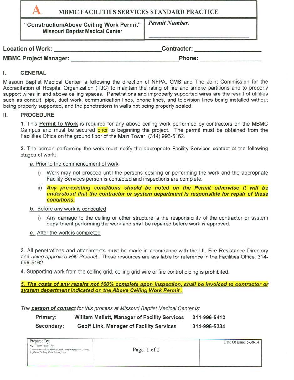
63 63
64 64

65 65

66 Appendix E: Wall Plate Labeling Diagram 66
67 Appendix F: CAT5e Conduit Fill Ratio Guide 6 Conduit Size Number of CAT5e Cables Fill Ratio Comments ½ 1 40% ½ 6 Experiment ¾ 5 40% ¾ 11 Experiment % 1 15 Experiment % 2 60 Experiment % Experiment Appendix G: CAT6 Conduit Fill Ratio Guide 7 Conduit Size Number of CAT6 Cables Fill Ratio Comments ½ 0 40% Not suitable for our 2 CAT6, 1 CAT5e solution ½ 2 Experiment Not suitable for our 2 CAT6, 1 CAT5e solution ¾ 2 40% ¾ 4 Experiment % 1 7 Experiment % 2 25 Experiment % 4 80 Experiment Appendix H: CAT5e/6 Cable Tray Fill Capacity Cable Tray Cable Tray Number of UTP Fill Ratio Comments Depth Width Cables (CAT 6) % Minimum Size % % % % % CAT 6A At an OD of.295, you can put 50 Belden 6A cables in a 4 conduit EZ Path Guidelines for fill ratio 6 Based on in-house experiment using a 24 length of ¾, 1, 2, and 4 conduit with Belden 1785A CAT5e UTP 7 Based on in-house experiment using a 24 length of ¾, 1, 2, and 4 conduit with Belden xxxxa CAT6 UTP 67
68 PATHWAY CAPACITIES Select cable size from the Cable Diameter columns on the left to determine the maximum capacity of pathways. Cable Diameter Pathway Cable Capacity mm inches EZD22 EZD33 EZD44 EZD IMPORTANT NOTICE: The above information is theoretical and is provided for estimation purposes only. Cable types, shapes, and diameters may vary and influence these calculations. Therefore, THE ACCURACY OF THIS INFORMATION CANNOT BE GUARANTEED. Page 1 EZ-Path Cable Capacity Chart ZSTI
69 Appendix I: WUSM/TFC/BJC BEF/ MAINTR/ TR Power Requirements The appropriate WUSM/TFC/BJC Project Manager will determine how many of each and the exact location of the power outlets at the beginning of each project. The intent of this section is to provide a general set of guidelines for the installation of power in WUSM/BJC/TFC communication spaces. The exact number and type of power receptacles will be determined at the onset of any project. Communicating these requirements to the contractor will be the responsibility of the assigned WUSM/BJC/TFC project manager/analyst. Power Conduit Installation Best Practices: All new conduit runs to racks will utilize a minimum size of 1 inside diameter to allow for future growth. Except existing areas where it is not reusable, consult with the appropriate Project Manager. Conduit will be routed down the outside of the closest vertical cable manager to the wall. At the base of this cable manager the conduit will be terminated into a junction box, which will be located inside the back of the cable management. Drilling through the cable managers to route conduits will not be permitted. Receptacles will be routed out of the top of the junction box and mount to the inside of the cable manager at the lowest available height. For multiple receptacle installations receptacle boxes will first be mounted side by side and if more space is required, stacked vertically. Conduits connecting junction boxes to the receptacle boxes will also be a minimum of 1 ID. Conduit extending to more than one rack will be routed along the base of the racks with junction boxes located in the back of each vertical cable manager passed through. As conduit passes between racks minimum height will be maintained in order to conserve usable rack space. i.e. Placed next to each other instead of being stacked on top of one another. Conduit or grounding and bonding will not pass through cable ladder rack (cable runway). If it is necessary to route conduit using the cable ladder rack as a path, it will be attached to the underside of the cable ladder rack and drop down the outside of the first available cable manager. Conduit will not run vertically inside a cable manager. An exception to this will be conduit connecting the receptacle boxes to the junction boxes at the base of the racks. All receptacles installed that utilize emergency power will be clearly marked with red. The preferred method is the utilization of red solid colored outlets for straight blade type receptacles and red rings on twist lock type receptacles. All receptacles will be clearly labeled with corresponding electrical panel and circuit designations. The accepted method is an adhesive backed printed label. No hand written labels will be allowed. Normal and emergency power conductors will never be placed in the same conduit. All electrical installations will utilize Electrical Metallic Tubing (EMT) conduit. No flexible conduit allowed. All communications circuits will utilize dedicated breakers. Circuits will not be shared with any receptacles located outside of the communications racks. Electrical boxes will be a Combination, in the base of the 10 Vertical Wire Manager, use an 8 X 8 X 4 metallic junction box to support 1 ID conduit knockout holes for future growth. 69

70 Appendix J - Elevator Voice Cable Design 70
PHYSICAL FACILITIES Consultant s Handbook Division 27 COMMUNICATIONS 0000 COMMUNICATIONS
 1 Introduction 1.1 In the design of Telecommunications systems in Purdue facilities, the overall consideration should be to understand and treat telecom as a utility. It should be assumed that all new
Communications Page 1 of 9
 Page 1 of 9 Last Update: April 23 rd, 2014 Introduction Design In the design of Telecommunications systems in Purdue facilities, the overall consideration should be to understand and treat telecom as a
The University of Texas at Austin September 30, 2011
 SECTION 27 05 26 GROUNDING AND BONDING FOR COMMUNICATIONS PART 1 - GENERAL 1.1 SUMMARY A. This section governs the products and execution requirements relating to furnishing and installing grounding and
Telecommunication Spaces
 Telecommunication Spaces October 19, 2016 Page 1 Revision History Telecommunication Spaces Standard Effective Date Email Version Contact Phone OIT-TS strevena@csustan.edu 1.0 Stan Trevena 209.667.3137
THOMAS JEFFERSON UNIVERSITY HOSPITAL STANDARD OPERATING PROCEDURE FOR THE BUILD OUT OF TELECOMMUNICATIONS ROOMS AND ASSOCIATED SPACES
 THOMAS JEFFERSON UNIVERSITY HOSPITAL STANDARD OPERATING PROCEDURE FOR THE BUILD OUT OF TELECOMMUNICATIONS ROOMS AND ASSOCIATED SPACES PREPARED BYBALA CONSULTING ENGINEERS, INC FOR THOMAS JEFFERSON UNIVERSITY
PCC Structured Cabling Standards
 PCC Structured Cabling Standards VERSION 2.0 07DEC16 Presented by: Portland Community College Information Technology Infrastructure Services Page 1 of 67 PCC Structured Cabling Standards 5 Purpose 5 CONTRACTOR
SECTION GROUNDING AND BONDING
 SECTION 16060 PART 1 GENERAL 1.01 DESCRIPTION A. Section includes requirements for an electrical grounding system, including electrodes, grounding rods, connectors, insulators, equipment grounding and
UNIVERSITY OF CHICAGO
 UNIVERSITY OF CHICAGO Information Technology Services - ITS TELECOMMUNICATIONS STRUCTURED CABLING GUIDELINES AND SPECIFICATIONS INFRASTRUCTURE SERVICES May 2015 1 Contents 1 Introduction... 4 2.0 Planning
NORTHWESTERN UNIVERSITY PROJECT NAME JOB # ISSUED: 03/29/2017
 SECTION 26 0526 - GROUNDING AND BONDING FOR ELECTRICAL SYSTEMS PART 1 - GENERAL 1.1 RELATED DOCUMENTS A. Drawings and general provisions of the Contract, including General and Supplementary Conditions
This product specification is written according to the Construction Specifications Institute MasterFormat, 2014 Update.
 Kaf-Tech Product Specification This product specification is written according to the Construction Specifications Institute MasterFormat, 2014 Update. SECTION 260519 METAL CLAD CABLE - MC-PLUS Neutral
B. Insulated Conductors: Stranded copper wire, green or green with yellow stripe insulation, insulated for 600 V, and complying with UL 83.
 SECTION 270526 - GROUNDING AND BONDING FOR COMMUNICATIONS SYSTEMS PART 1 - GENERAL 1.1 SUMMARY A. Section Includes: 1. Grounding conductors. 2. Grounding connectors. 3. Grounding busbars. 4. Grounding
UNDERGROUND SERVICES SECONDARY
 Reference UNDERGROUND SERVICES SECONDARY Underground services secondary... U- 1 General requirements for underground service... U- 2 Name of parts for underground service... U- 3 Conduit layouts... U-
PATHWAYS FOR COMMUNICATIONS SYSTEMS
 270528 PATHWAYS FOR PART 1 GENERAL 1.1 WORK INCLUDED A. Provide all labor, materials, and equipment for the complete installation of work called for in the Contract Documents. 1.2 SCOPE OF WORK A. This
University of Florida Telecommunication Standards April 2005
 University of Florida Telecommunication Standards April 2005 This document is designed to assist certified designers such as Professional Engineers and RCDD s in the preparation of telecommunications documents
Title: YALE OFFICE OF FACILITIES PROCEDURE MANUAL Chapter: 01 - Yale Design Standard Division: Electrical Standards
 Date Description of Change Pages / Sections Modified ID 6/15/16 Updated format, division title, and removed references to other sections. - mgl44 A. Summary This section contains design criteria for the
300 North Main Street Versailles, Kentucky (859)
") KCTCS Information Technology Division 250000 and 270000 300 North Main Street Versailles, Kentucky 40383 (859) 256-3100 Version 4.0 April 5, 2007 Notice This document is a living document and is subject
KCTCS Information Technology Division 250000 and 270000 300 North Main Street Versailles, Kentucky 40383 (859) 256-3100 Version 4.0 April 5, 2007 Notice This document is a living document and is subject
SECTION (Master Template Final-05) ELECTRICAL BOXES. A. Provide boxes for electrical equipment and wiring devices as follows:
 ELECTRICAL BOXES. A. Provide boxes for electrical equipment and wiring devices as follows:") SECTION 16130 (Master Template Final-05) ELECTRICAL BOXES PART 1 GENERAL 1.01 SECTION INCLUDES A. Provide boxes for electrical equipment and wiring devices as follows: 1. Wall and ceiling outlet boxes.
SECTION 16130 (Master Template Final-05) ELECTRICAL BOXES PART 1 GENERAL 1.01 SECTION INCLUDES A. Provide boxes for electrical equipment and wiring devices as follows: 1. Wall and ceiling outlet boxes.
OKLAHOMA STATE UNIVERSITY - BUILDING DESIGN STANDARDS
 Page 1 PART 1 - GENERAL 1.01 Intent of Document The information included in this section is intended to identify the SPECIFIC ITEMS required by Oklahoma State University (OSU) in the design and construction
SECTION PATHWAYS FOR COMMUNICATIONS SYSTEMS
 SECTION 270528 PATHWAYS FOR COMMUNICATIONS SYSTEMS PART 1 - GENERAL 1.1 SUMMARY A. Section Includes: 1. Communications equipment coordination and installation. 2. Sleeves for pathways and cables. 3. Raceway
2008 NEC Guide Lines for Home Owner Doing Electrical Work on their Property
 2008 NEC Guide Lines for Home Owner Doing Electrical Work on their Property A brief summary of the most used code references for residential wiring State of Idaho Division of Building Safety Electrical
B. Provide a complete conduit system with associated couplings, connectors, and fittings.
 SECTION 26 05 33 PART 1 - GENERAL 1.01 WORK INCLUDED A. Comply with the provisions of Sections 260500. B. Provide a complete conduit system with associated couplings, connectors, and fittings. 1.02 RELATED
UNLV Campus Wiring Specification September 15, 2016
 UNLV Campus Wiring Specification September 15, 2016 1. Part I - General... 4 1.0. Purpose... 4 1.1. Contractor Qualifications... 4 1.2. Applicable Regulations... 5 A. Related Documents... 5 1.3. Submittal...
City and County of San Francisco CONTRACT No A SFO - Data Center, Building 60 SECTION CABLE TRAYS FOR COMMUNICATIONS SYSTEMS
 SECTION 27 05 36 CABLE TRAYS FOR COMMUNICATIONS SYSTEMS PART 1 - GENERAL 1.1 SCOPE OF WORK A. Cable Trays for Communications Cabling 1. Cable Trays 2. Cable Runways 3. Basket Tray B. Cable Tray Support
A/E Design Deliverable Checklist
 A/E Design Deliverable Checklist Design deliverables for the Design Development phase shall include all items listed in the Design Development column as well as those all items listed in the Schematic
Telecommunications Infrastructure Design Standards
 Telecommunications Infrastructure Design Standards (Version 13) IF YOU HAVE ANY QUESTIONS OR COMMENTS ABOUT THIS INSTALLATION GUIDE PLEASE VISIT THE COMPLETE TELECOMMUNICATIONS INFRASTRUCTURE DESIGN STANDARDS
Telecommunications Cabling System Technical Specification
 1.0 INTRODUCTION Telecommunications Cabling System Technical Specification 1.1 PURPOSE The intent of this document is to provide a standard specification that will be used for all University of Northern
SECTION P -- CABLE VAULT AND CABLE ENTRANCE FACILITY
 INSTLLTION REQUIREMENTS Section P, TT-TP-76300 T&T January 2012 Revised July, 2012 SECTION P -- CLE VULT ND CLE ENTRNCE FCILITY CONTENTS PGE 1. GENERL... P-1 1.1. Introduction... P-1 1.2. Non-Insulating
WIRING METHODS CHAPTER 38
 CHAPTER 38 WIRING METHODS SECTION E3801 GENERAL REQUIREMENTS E3801.1 Scope. This chapter covers the wiring methods for services, feeders and branch circuits for electrical power and distribution. E3801.2
Electric Service Standards
 V: 1 of 6 A. Padmounted Requirements Complete requirements are contained in FPL specifications given to Customers for individual projects. Typical pad mounted transformer requirements include, but are
CONSOLIDATED EDISON COMPANY OF NEW YORK, INC Van Dam Street Long Island City, NY ELECTRIC METER SHOP DEPARTMENT
 CONSOLIDATED EDISON COMPANY OF NEW YORK, INC. 48-05 Van Dam Street Long Island City, NY 11101 ELECTRIC METER SHOP DEPARTMENT METER ENGINEERING SPECIFICATION MES-350 REVISION 3 June 2016 EFFECTIVE DATE
Revision 1 RAM ELEVATORS. Elevator Electrical Planning Guide. RAM Manufacturing Ltd
 RAM ELEVATORS Elevator Electrical Planning Guide This guide is intended for people with an understanding of electricity. If you are not, please consult a licensed electrician as errors in application of
SECTION LOW-VOLTAGE ELECTRICAL POWER CONDUCTORS AND CABLES (24 Volt AC/DC or Less)
") SECTION 260523 LOW-VOLTAGE ELECTRICAL POWER CONDUCTORS AND CABLES (24 Volt AC/DC or Less) PART 1 - GENERAL 1.1 SUMMARY A. Related Documents: 1. Drawings and general provisions of the Subcontract apply
SECTION 260523 LOW-VOLTAGE ELECTRICAL POWER CONDUCTORS AND CABLES (24 Volt AC/DC or Less) PART 1 - GENERAL 1.1 SUMMARY A. Related Documents: 1. Drawings and general provisions of the Subcontract apply
INFRASTRUCTURE STANDARD
 Telecommunications and Network Services INFRASTRUCTURE STANDARD December 18, 2017 Revision 1.6 Download PDF at: www.uvm.edu/telcom UNIVERSITY OF VERMONT TELECOMMUNICATIONS INFRASTRUCTURE STANDARD January
Design Guidelines for Information Technology. University of New Mexico Information Technology Services
 Hospital Information Technology Services Design Guidelines for Information Technology Infrastructure & Facilities Vantage Report: April 30, 2003 Edited March 21, 2006, Edited February 27, 2008 Hospital
DOWNTOWN UNDERGROUND NETWORK SECONDARY SERVICES GUIDELINES
 Guidelines effective March 5, 2007 NES is committed to providing safe, reliable electric service at a reasonable price for all of our customers. These guidelines offer direction for activities relating
A/E Design Deliverable Checklist
 A/E Design Deliverable Checklist Design deliverables for the Design Development phase shall include all items listed in the Design Development column as well as those all items listed in the Schematic
PIP PCEPA003 Process Analyzer System Field Installation Guidelines
 January 2016 Process Control PIP PCEPA003 Process Analyzer System Field Installation Guidelines PURPOSE AND USE OF PROCESS INDUSTRY PRACTICES In an effort to minimize the cost of process industry facilities,
Specification Lightning Protection Systems
 Specification Lightning Protection Systems General: Summary A) This Section specifies the lightning protection system for the building(s) or structure(s). This system provides safety for the building and
STANDARDS SECTION (16650) COMMUNICATIONS (TEL-DATA-VIDEO) ELECTRICAL SYSTEM (Rev. Jun 2011)
 COMMUNICATIONS (TEL-DATA-VIDEO) ELECTRICAL SYSTEM (Rev. Jun 2011)") STANDARDS SECTION 260000 (16650) COMMUNICATIONS (TEL-DATA-VIDEO) ELECTRICAL SYSTEM (Rev. Jun 2011) PART 1 GENERAL 1.00 DESCRIPTION A. Furnish and install a complete Communications (Telephone/Data/Video)
STANDARDS SECTION 260000 (16650) COMMUNICATIONS (TEL-DATA-VIDEO) ELECTRICAL SYSTEM (Rev. Jun 2011) PART 1 GENERAL 1.00 DESCRIPTION A. Furnish and install a complete Communications (Telephone/Data/Video)
Section 2: Underground
 Section 2: Underground GENERAL INSTALLATION REQUIREMENTS FOR UNDERGROUND FACILITIES Underground electric service and meter location will be established by NHEC upon site visit. In some instances the type,
CONDUITS AND FITTINGS
 CONDUIT AND FITTINGS Rigid Steel Conduit 3801 Rigid PVC Conduit 3803 HDPE Conduit 3803 Flexible Non Metallic Liquid Tight Conduit Type LFNC-B 3804 PVC Coated Urethane Lined Galvanized Rigid Steel Conduit
CHAPTER 11 CONDUITS AND FITTINGS
 CONDUITS AND FITTINGS CHAPTER 11 CONDUITS AND FITTINGS The standards and requirements for conduits and fittings used for traffic control signal and lighting systems are presented in this chapter. 11.1
UNIFIED FACILITIES GUIDE SPECIFICATIONS
 USACE / NAVFAC / AFCEC / NASA UFGS-27 05 29.00 10 (August 2011) --------------------------------- Preparing Activity: USACE New UNIFIED FACILITIES GUIDE SPECIFICATIONS References are in agreement with
SECTION 10 TEMPEST DESIGN STANDARDS
 Page 1 SECTION 10 DESIGN STANDARDS 10.1 GENERAL 10.1.1 Correlation and Coordination A. This section provides standards for the design of all facilities or areas that require electromagnetic containment
INSTALLATION INSTRUCTIONS FOR ELECTRICAL CONTRACTORS
 INSTALLATION INSTRUCTIONS FOR ELECTRICAL CONTRACTORS Rev. 1.5 1.10.13 Toll free (800) 288-6000 or www.hubbell-wiring.com P a g e 0 IMPORTANT SAFETY INSTRUCTIONS SAVE THESE INSTRUCTIONS WARNING- When using
ELECTRIC METERING GENERAL
 1.0 INDEX 1.0 INDEX 2.0 SCOPE 3.0 GENERAL REQUIREMENTS 4.0 EQUIPMENT 5.0 METER REQUIREMENTS 6.0 METER FACILITIES 7.0 ELECTRICAL CONNECTIONS 2.0 SCOPE This guide covers general requirements and codes for
GUIDELINES. SPECIFICATION COMMUNICATIONS CABINETS AND EQUIPMENT ROOMS (Rev TAB)
") PART 1 GENERAL 1.01 SUMMARY SPECIFICATION 271100 COMMUNICATIONS CABINETS AND EQUIPMENT ROOMS (Rev 06-25-2015- TAB) A. This section includes the specifications for constructing and building out of Telecommunications
PART 1 GENERAL 1.01 SUMMARY SPECIFICATION 271100 COMMUNICATIONS CABINETS AND EQUIPMENT ROOMS (Rev 06-25-2015- TAB) A. This section includes the specifications for constructing and building out of Telecommunications
A. Product Data shall be provided for each type of product indicated.
 32 31 13 CHAIN LINK FENCES AND GATES SECTION 1 GENERAL 1.1 SUMMARY This Section includes the following: 1. Chain Link Fences 2. Gates for Chain Link Fences. See electrical specifications for electrical
GV 001 Equipment Bases and Enclosures General Information
 Eq u ip me n tba s e s a n d En c lo s u re s Ge n e ra lin fo rma tio n E n g in e e r :R.An th o n GV0 0 1 Ap p r o v e r :Jo s h u a Jo n e s Ap r 1 7 2 0 Ap r1 7 GV 001 Equipment Bases and Enclosures
Welcome to Douglas County PUD
 Welcome to Douglas County PUD We are committed to providing the best possible utility services at the lowest possible cost consistent with sound business principles. To better serve you, please fill out
TELECOMMUNICATIONS DESIGN AND CONSTRUCTION GUIDELINES
 TELECOMMUNICATIONS DESIGN AND CONSTRUCTION GUIDELINES 2013 Design Guidelines 1 P age 1.0 General 4 2.0 Distribution System 2.1 Communications Manhole 5 2.1.1 Entrance Duct 5 2.1.2 Ductbank between Manholes
2015 Code Rollout Meeting Q & A
 1 SECTION QUESTION SaskPower Inspections Dept. ANSWER 2 3 4 5 6 7 8 9 10 11 12 15-02-024 15-02-200 15-02-200 15-02-200 15-02-314 Are existing single or double 'weather proof when not in use' covers allowed
Section ARMORED MEDIUM VOLTAGE CABLES SHIELDED 3 CONDUCTOR POWER CABLE - INTERLOCKED ARMOR
 PART 1 - GENERAL Section 26 05 15 SHIELDED 3 CONDUCTOR POWER CABLE - INTERLOCKED ARMOR 1.1 Cable shall be 15 kv, shielded, three conductor with ground, stranded copper, with continuously welded and corrugated
Revisions for the 2011 National Electrical Code - Part 2
 PDHonline Course E356 (3 PDH) Revisions for the 2011 National Electrical Code - Part 2 Instructor: Patrick Ouillette 2012 PDH Online PDH Center 5272 Meadow Estates Drive Fairfax, VA 22030-6658 Phone &
UNIVERSITY OF CALIFORNIA, SAN DIEGO
 UNIVERSITY OF CALIFORNIA, SAN DIEGO BERKELEY DAVIS IRVINE LOS ANGELES MERCED RIVERSIDE SAN DIEGO SAN FRANCISCO SANTA BARBARA SANTA CRUZ OFFICE OF THE ASSIST ANT VICE CHANCELLOR CAMPUS ARCHITECT- FACILITIES
Basic Requirements for Residential Electrical Installations
 Basic Requirements for Residential Electrical Installations Wayne County Building Department 428 West Liberty Street Wooster, Ohio 44691 Phone: 330-287-5525 Fax: 330-287-5649 This brochure is intended
Douglas County Traffic Signal Installation Guidelines (January 2013)
") Douglas County Traffic Signal Installation Guidelines (January 2013) The following guidelines are minimum requirements for equipment installation. Section A. Poles and Foundations ( Wood, Concrete, Mast
Douglas County Traffic Signal Installation Guidelines (January 2013) The following guidelines are minimum requirements for equipment installation. Section A. Poles and Foundations ( Wood, Concrete, Mast
DESIGN AND CONSTRUCTION STANDARDS. Section 2: Standards for Specific Categories of Work. Laboratory Standards
 Laboratory Standards These criteria include general planning guidelines. They are intended for use of Designers during the design phases of the project. Planning Assumptions Overview In order to maximize
Underground Residential Distribution (Specifications for Installation) PES March 2008 Spec 11
 PES March 2008 Spec 11") Underground Residential Distribution (Specifications for Installation) PES March 2008 Spec 11 Underground Residential Distribution (URD) Index General Discussion... 1-2 Description... 3-7 Drawings (Available
Underground Residential Distribution (Specifications for Installation) PES March 2008 Spec 11 Underground Residential Distribution (URD) Index General Discussion... 1-2 Description... 3-7 Drawings (Available
Contact Clark Public Utilities Construction Services department at (360) to initiate a request for service.
 to initiate a request for service.") CHAPTER3 Clark Public Utilities Commercial Electric Service Handbook Commercial Underground Services Preparing for the installation The following checklist will assist in preparing a project for the installation
CHAPTER3 Clark Public Utilities Commercial Electric Service Handbook Commercial Underground Services Preparing for the installation The following checklist will assist in preparing a project for the installation
Basic Service. This Section provides information regarding a. Introduction
 Basic Service Introduction This Section provides information regarding a new electric Basic Service for a single phase service less than or equal to 400 amps, and a three phase service less than 50kW.
SPECIFICATION FOR THE DEVELOPMENT OF LPA CLEAN ROOM INFRASTRUCTURE Description of work
 SPECIFICATION FOR THE DEVELOPMENT OF LPA CLEAN ROOM INFRASTRUCTURE Description of work Creation of Three clean area rooms (Master Mix, Amplification and Hybridization rooms) for Line Probe Assay with two
Wiring Standards and Guidelines
 2017 Wiring Standards and Guidelines Longwood University This document and its references are intended to assist the architect/designer and the installer in the base guidelines and standards utilized at
INTER-BUILDING CONDUIT & MANHOLE SYSTEM. Table of Contents PART 1 GENERAL 1 A. RELATED DOCUMENTS 1 B. SCOPE OF WORK 1 PART 2 PRODUCTS 6
 UNIVERSITY CONTACT: Network Services (302) 831-3722 INTER-BUILDING CONDUIT & MANHOLE SYSTEM Table of Contents PART 1 GENERAL 1 A. RELATED DOCUMENTS 1 B. SCOPE OF WORK 1 PART 2 PRODUCTS 6 A. MATERIALS AND
Document No Issue Date: May 15, 2012
 Professional Engineer Authenticated TELUS Residential Service Conduit Requirements For Stand-Alone Homes and Duplexes in Fibre Only Communities Beginning in January 2010 TELUS began designing new subdivisions
BASEMENT FINISH PERMIT AND BUILDING CODE REQUIREMENTS (REVISED 3/6/2018)
") BASEMENT FINISH PERMIT AND BUILDING CODE REQUIREMENTS (REVISED 3/6/2018) PERMIT SUBMITTAL CHECKLIST: Signed and completed Building Permit application form. A separate Electrical permit is required from
BASEMENT FINISH PERMIT AND BUILDING CODE REQUIREMENTS (REVISED 3/6/2018) PERMIT SUBMITTAL CHECKLIST: Signed and completed Building Permit application form. A separate Electrical permit is required from
SECTION INSULATED WIRE AND CABLE
 SECTION 16120 INSULATED WIRE AND CABLE PART 1 GENERAL 1.01 DESCRIPTION A. This section covers the contract item Insulated Wire and Cable, which includes the following items with accessories, and appurtenances:
Large Basic Service. This Section applies to members requiring new. Introduction. Service Types
 Large Basic Service Introduction This Section applies to members requiring new Large Basic electric service installations, greater than 400 amps single phase and greater than 50kW three phase. This Section
1. Vertical reciprocating conveyor, Hydraulic straddle VRC.
 PART 1: GENERAL 1.01 Section Includes: 1. Vertical reciprocating conveyor, Hydraulic straddle VRC. a. Machine, controller, platform, structural steel hoist frame. b. Wire mesh enclosure and gates. Related
Addendum 1.0. For Lagrange Library Specification 1.0. Technology Consultants Fort Wayne, Indiana
 Addendum 1.0 For Lagrange Library Specification 1.0 Technology Consultants Fort Wayne, Indiana TECHNICAL SPECIFICATIONS FOR TELECOMMUNICATION DISTRIBUTION FACILITIES AND INSTALLATION PROCEDURES For Lagrange
Electric Service Handbook
 Electric Service Handbook Revised August 2017 Contact Information Telephone (253): Electrical Inspection Office 502-8277 7:30 am - 4:30 pm Electrical Inspectors Area Map on Website 7:30 am - 8:30 am Automated
ELECTRICAL SAFETY INSPECTION REPORT
 ELECTRICAL SAFETY INSPECTION REPORT Zirabo Bazar, Ashulia, Savar, Dhaka, Bangladesh Factory List: 1. Inspected by: Khan & Tapu Report Generated by: Khan Inspected on Feb 6 th 2015 SUMMARY factory building
SECTION CHAIN-LINK FENCES AND GATES 02821/1
 SECTION 02821 - CHAIN-LINK FENCES AND GATES 02821/1 PART 1 - GENERAL 1.1 SUMMARY A. This Section includes the following: 1. Chain-Link Fences: 2. Gates: horizontal slide or swing. 3. Fences installed where
SECTION I -- IRONWORK
 SECTION I -- IRONWORK CONTENTS PAGE 1. GENERAL... I-2 1.1. Introduction... I-2 2. REQUIREMENTS... I-2 2.1. General... I-2 2.2. Auxiliary Framing... I-2 2.3. High Seismic Risk Zone Requirements... I-3 2.4.
(Condensed from National Electric Code)
") WIRING, SPECIFICATIONS, INSPECTION, AND METER INSTALLATION PROCEDURES FOR RESIDENTIAL CUSTOMERS SERVED BY SOUTHWEST ARKANSAS ELECTRIC COOPERATIVE CORPORATION Effective April 1, 1974 Revised February 3,
WIRING, SPECIFICATIONS, INSPECTION, AND METER INSTALLATION PROCEDURES FOR RESIDENTIAL CUSTOMERS SERVED BY SOUTHWEST ARKANSAS ELECTRIC COOPERATIVE CORPORATION Effective April 1, 1974 Revised February 3,
B. Accept materials on site in original factory packaging, labeled with manufacturer s identification.
 SECTION 26 05 02 - BASIC ELECTRICAL REQUIREMENTS PART 1 - GENERAL 1.1 SUMMARY A. Work Included: Furnish all labor, material, services and skilled supervision necessary for the construction, erection, installation,
ITEM L-119 AIRPORT OBSTRUCTION LIGHTS DESCRIPTION
 SECTION 74 AIRPORT OBSTRUCTION LIGHTS (FAA L-119) 74-1 GENERAL The Contractor shall perform all work required by the plans and specifications for construction of obstruction lights in accordance with the
UNIVERSITY OF ALASKA FAIRBANKS DIVISION 14 - CONVEYING EQUIPMENT DESIGN STANDARDS SECTION
 PART 1 - GENERAL 1.01 Elevator manufacturer to provide equipment and installation warranty and maintenance services for at least one year after acceptance. This requires routine monthly inspection, emergency
RESIDENTIAL BUILDING REQUIREMENTS
 RESIDENTIAL BUILDING REQUIREMENTS Residential Building Requirements This is an informational booklet with some of the general residential construction requirements taken from the codes adopted by Campbell
Typical Finished Basement Details
 Albemarle County, Virginia Typical Finished Basement Details Based on the 2012 Virginia Residential Code Finished basements must be constructed in conformance with these details. For requirements, details
MINIMUM REQUIREMENTS FOR STRUCTURED CABLING
 Last Reviewed 1/6/2017 MINIMUM REQUIREMENTS FOR STRUCTURED CABLING WEST VIRGINIA UNIVERSITY INFORMATION TECHNOLOGY SERVICES Telecommunications and Network Operations 1. GENERAL... 4 1.1 SUMMARY... 4 1.2
SECTION RADIATION SHIELDING ENCLOSURE Low Intensity Radiation Protection
 SECTION 13090 RADIATION SHIELDING ENCLOSURE Low Intensity Radiation Protection Prepared by: 90 Dayton Avenue, Unit 4B, Suite 13 Passaic, NJ 07055 (973) 574-9077 13090-1 LOW INTENSITY RADIATION PROTECTION
The Canadian Electrical Code (Saskatchewan Amendments) Regulations, 1999
 Regulations, 1999") CANADIAN ELECTRICAL CODE 1 The Canadian Electrical Code (Saskatchewan Amendments) Regulations, 1999 Repealed by Chapter E-6.3 Reg 8 (effective June 24, 2003). Formerly Chapter E-6.3 Reg 6 (effective March
CANADIAN ELECTRICAL CODE 1 The Canadian Electrical Code (Saskatchewan Amendments) Regulations, 1999 Repealed by Chapter E-6.3 Reg 8 (effective June 24, 2003). Formerly Chapter E-6.3 Reg 6 (effective March
Standards for Communications Infrastructure
 Standards for Communications Infrastructure C&IT Infrastructure And Operations Wayne State University 5925 Woodward Detroit, Michigan 48202-3555 Revised: 13 March 2015 By: Pete Garabedian 1 This document
TYPICAL INSTALLATION INSTRUCTIONS
 TYPICAL INSTALLATION INSTRUCTIONS Environment One Grinder Pump Feature Identification 1. Grinder Pump Basin High density polyethylene (HDPE) 2. Accessway Cover Painted Steel 3. Electrical Quick Disconnect
Effective June, Eaton-Durham Model # UTRS223ACH. Siemens, Model # SUAS877-PG. (or Landis & Gyr # UAS877-PG) Milbank. Model # U1980-O.
 Milbank. Model # U1980-O.") Siemens, Model # SUAS877-PG (or Landis & Gyr # UAS877-PG) Eaton-Durham Model # UTRS223ACH Milbank Midwest Model # U980-O UTRS223AMEP These are some examples of the single meter sockets we require for underground
Siemens, Model # SUAS877-PG (or Landis & Gyr # UAS877-PG) Eaton-Durham Model # UTRS223ACH Milbank Midwest Model # U980-O UTRS223AMEP These are some examples of the single meter sockets we require for underground
3M Intelligent Return Plus and Sorter System SL. Architect/Contractor's Package
 3M Intelligent Return Plus and Sorter System SL Architect/Contractor's Package 3M, 2015. All rights reserved. 3M Intelligent Return Plus and Sorter System SL Architect/Contractor's Package, 78-8129-4937-4B
ELECTRICAL SAFETY INSPECTION REPORT
 ELECTRICAL SAFETY INSPECTION REPORT ACTIVE COMPOSITE MILLS LTD. Dewan Idris Road, Zirabo, Ashulia, Savar, Dhaka, Bangladesh Factory List: 1. Active Composite Mills Ltd. Inspected by: Hemlal Report Generated
SECTION HANGERS AND SUPPORTS FOR ELECTRICAL SYSTEMS
 SECTION 26 05 29 HANGERS AND SUPPORTS FOR ELECTRICAL SYSTEMS PART 1 GENERAL 1.1 DESCRIPTION A. Scope: 1. CONTRACTOR shall provide all labor, materials, equipment, and incidentals as shown, specified, and
High Piled Combustible Storage Guideline
 Moreno Valley High Piled Combustible Storage Approved and Authorized By: Adria Reinertson, Fire Marshal Issued: May 5, 2017 Rev: 7-28-16 City of Moreno Valley Fire Department Page 1 of 19 High Piled Storage
SECTION HVAC INSTRUMENTATION AND CONTROLS INSTALLATION
 I. GENERAL A. NOTES SECTION 15957 (Applicable to IUPUI Only) 1. The University has a pre-purchase agreement (PPA) with Johnson Controls (JCI) and Siemens Building Technologies (SBT). The University will
Low-profile, 11U high cabinets hold networking equipment, servers, and phone equipment.
 RM140A-R3 RM140A-M-R3 RM145A-R3 RM145A-M-R3 Small Office/Home Office (SOHO) Cabinets Low-profile, 11U high cabinets hold networking equipment, servers, and phone equipment. Fit under most desktops in the
MESH FLOOR HEATING SYSTEMS INSTALLATION INSTRUCTIONS
 MESH FLOOR HEATING SYSTEMS INSTALLATION INSTRUCTIONS MESH FLOOR HEATING SYSTEMS TOLL FREE: 1.800.778.WARM(9276) PHONE: 604.529.4400 FAX: 604.529.4404 EMAIL: RES.customercare@pentair.com www.nuheat.com
Specifications Electrical Metallic Tubing (EMT)
") T& Fittings Specifications Electrical Metallic Tubing (EMT) Ref. CEC Rule 12-000 not exceeding 750 Volts Electrical Metallic Tubing (EMT) is similar to rigid steel conduit but is much lighter, weighing
T& Fittings Specifications Electrical Metallic Tubing (EMT) Ref. CEC Rule 12-000 not exceeding 750 Volts Electrical Metallic Tubing (EMT) is similar to rigid steel conduit but is much lighter, weighing
Pre-installation checklist. 3. Project manager has read specifications, and specs to be on-site during work.
 Pre-installation checklist 1. Contractor qualifications verified. 2. Project manager is Belden/CDT installer certified. 3. Project manager has read specifications, and specs to be on-site during work.
SECTION VIBRATION CONTROLS FOR HVAC PIPING AND EQUIPMENT
 SECTION 230548 - PART 1 - GENERAL 1.1 SUMMARY A. This Section includes the following: 1. Elastomeric Isolation pads. 2. Elastomeric Isolation mounts. 3. [Freestanding] [Restrained] [Freestanding and restrained]
SECTION RADIO FREQUENCY SHIELDING ENCLOSURE RF Welded System
 SECTION 13096 RADIO FREQUENCY SHIELDING ENCLOSURE RF Welded System Prepared by: 90 Dayton Avenue, Unit 4B, Suite 13 Passaic, NJ 07055 (973) 574-9077 13096-1 RF WELDED SYSTEM PART 1 GENERAL 1.1 SECTION
Cavity Design and U-Channel Relationship
 This section outlines the factors that determine the size of the cavity and the cavity placement in relationship to the U-channel, which will be embedded into the column during construction. You will learn
2009 IBC Section 1024 Approved Luminous Egress Path Markings
 2009 IBC Section 1024 Approved Luminous Egress Path Markings Where Required Buildings of Groups A (Assembly), B (Business), E (Education), I (Institutional), M (Mercantile) and R-1 (Residential transient
2007 Title 24 Accessibility Code Updates and ADA Issues
 2007 Title 24 Accessibility Code Updates and ADA Issues C.A.S.H. Workshop June 2007 Introduction Update on ADA Certification of the California Building Code Overview of significant changes to accessibility