HURRICANE SANDY LIMITED REEVALUATION REPORT UNION BEACH, NEW JERSEY DRAFT ENGINEERING APPENDIX SUB APPENDIX B-2 FLOODWALL PILE ANALYSES EAST WALLS
|
|
|
- Caroline Shaw
- 6 years ago
- Views:
Transcription
1 HURRICANE SANDY LIMITED REEVALUATION REPORT UNION BEACH, NEW JERSEY DRAFT ENGINEERING APPENDIX SUB APPENDIX B-2 FLOODWALL PILE ANALYSES EAST WALLS Revised March 2015
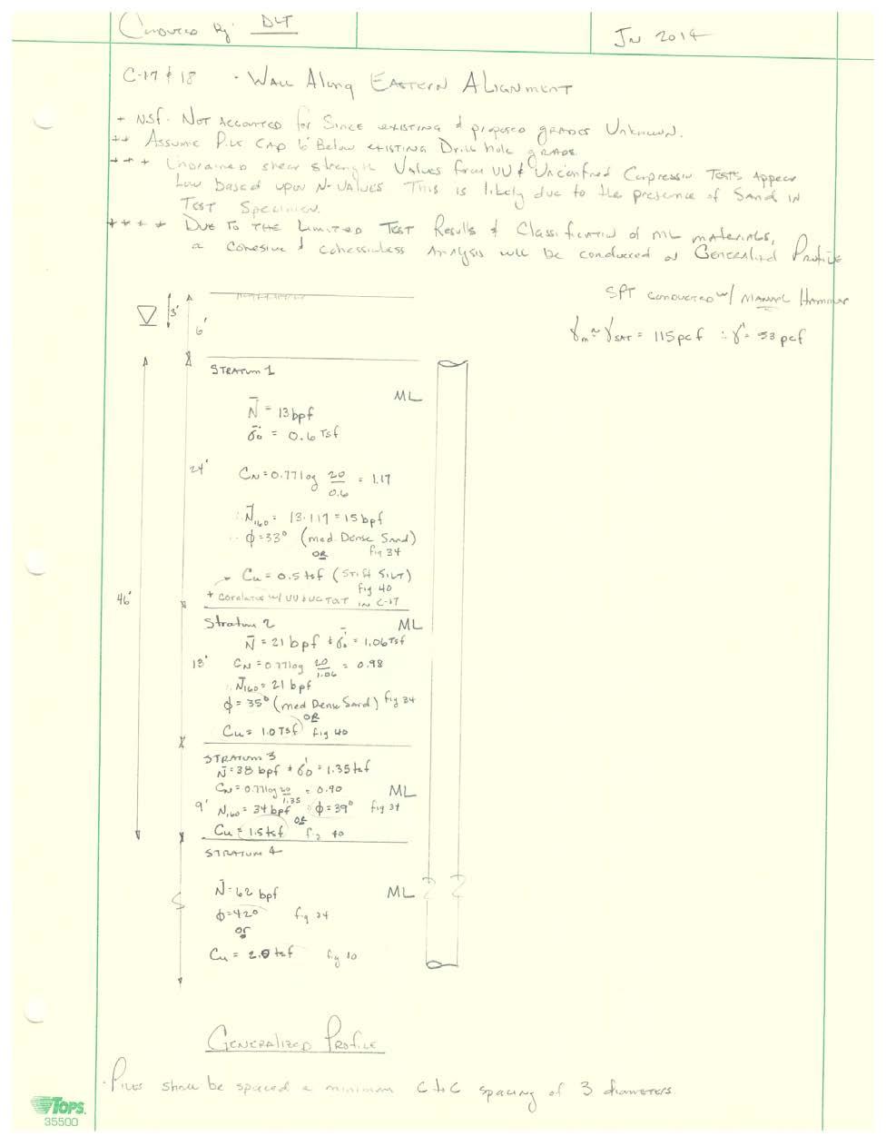
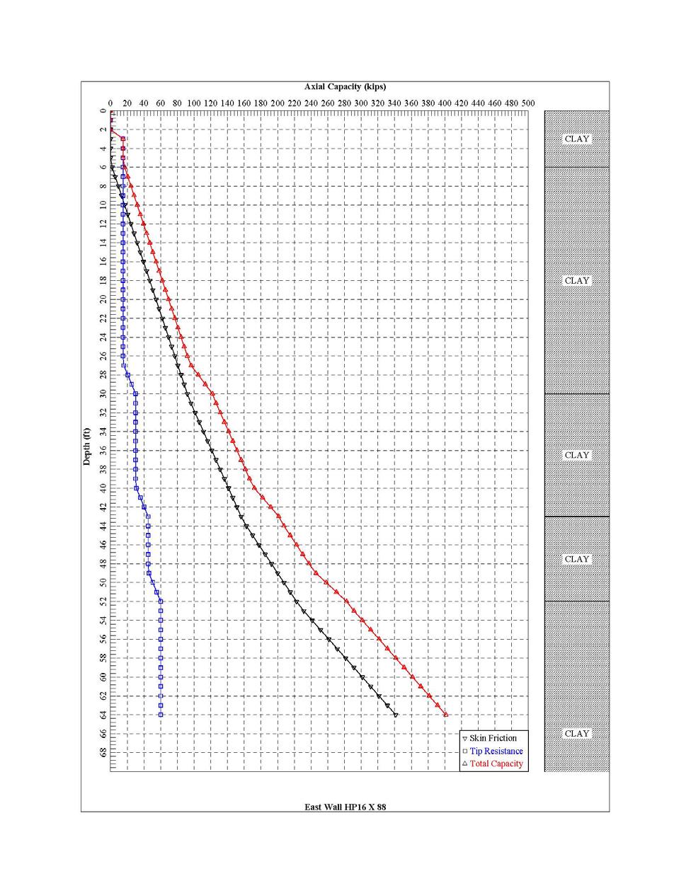
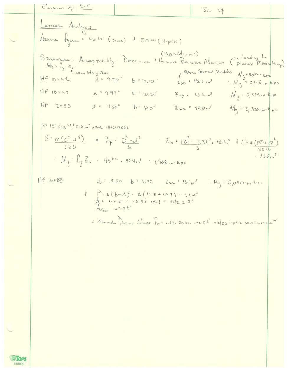
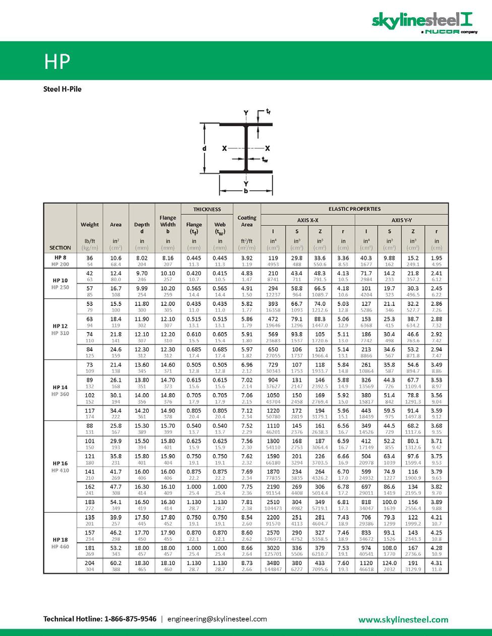
2 Preliminary Flood Wall Pile Analysis East Alignment Union Beach, New Jersey February 2014(revised March 2015) 1. GENERAL: Preliminary Axial compressive, uplift and lateral load capacities are provided below to the Structural Engineer to determine the preliminary dimension of the pile caps for the pile supported T-walls along the East Alignment. Pile capacities for the West Flood Wall Alignment will be submitted under a different document. 2. SOIL PROFILE: Drill holes C-17, C-18, and C-20 obtained from the 2003 Feasibility Report dated September 2003 were utilized to develop a Generalized Soil Profile which was utilized for the preliminary pile analysis. Based upon observations and interpretations of the limited laboratory test results and borings logs, it is unclear whether the clayey silts and silty sands would behave as a clay (undrained condition) or a sand (drained condition). Therefore, analysis for both sand and clay were conducted for both the axial and lateral pile analysis and the most conservative results utilized. Based upon these analysis, the sand analysis governed for the axial capacity and the clay analysis governed for the lateral analysis. Specific assumptions for each analysis are discussed below. 3. MINIMUM PILE SPACING: Piles shall be spaced no closer than a minimum center- to- center spacing of 3 diameters. The lateral load analysis utilized P multipliers (Pm) to account for group effects. 4. AXIAL PILE ANALYSIS: APILE plus 5.0 software developed by ENSOFT was utilized to compute the axial pile capacities. The software evaluated the axial capacity for four different methods (FHWA, USACE, Lambda and API); the capacities provided in the following table are computed from the USACE method. Estimated axial Pile loadings as provided by the Structural Engineer range from 24 kips to 234 kips in axial compression and 15 kips in axial tension. Five different pile types,(1) 12-inch pipe pile with inch wall thickness driven open ended, (2) HP10 X 42, (3) HP10 X 57, (4) HP12 X 53, and (5) HP16 X 88 were analyzed and their allowable axial capacities provided for three different pile lengths (30, 40 and 50 feet). The following assumptions were utilized in the analysis: a. Based upon the 2003 Feasibility report, it was assumed that the bottom of the pile cap is 6 feet below grade. b. Existing and finished grades are unknown and therefore down drag was not considered in this preliminary analysis. This shall be revisited during the final design. c. Since a static load test will be required during construction, a factor of safety of 2 was implemented for the allowable bearing capacity. 2
3 Preliminary Allowable Axial Pile Capacities (with factor of safety of 2) 12 Diameter Pipe w/0.312 wall thickness (kips) HP10 X 42 (kips) HP10 X 57 (kips) HP12 X 53 (kips) HP16 X 88 Qall for 30 length NA Tall for 30 length NA Qall for 40 length NA Tall for 40 length NA Qall for 50 length NA Tall for 50 length NA Qall for 58 length NA NA NA NA 200 Tall for 58 length NA NA NA NA 170 Q all = Allowable axial capacity in compression; T all = Allowable axial capacity in Tension (Uplift); NA = Not analyzed 5. LATERAL PILE ANALYSIS: LPILE plus version software developed by ENSOFT was utilized for the lateral pile analysis. Four different pile types,(1) 12-inch pipe pile with a inch wall thickness driven open ended, (2) HP10 X 42, (3) HP10 X 57, (4) HP12 X 53, and (5) HP16 X 88 at lengths of 30 feet were analyzed and the results tabulated below for each section. The following assumptions were made in the analysis: a. Since the head restraint was unknown, maximum moments and lateral deflections for both free head and fixed head are provided. Since it is anticipated that a partially fixed restraint will be utilized, a maximum free head deflection of 0.75 inches was assumed as the governing deflection. b. Axial loading was unknown at the time of analysis and therefore not implemented in the lateral analysis. c. Top of pile was conservatively assumed at 3 feet below grade in lieu of 6 feet as indicated in the axial capacity analysis. d. A cyclic loading of 500 cycles was utilized. This is an estimate and will need to be further investigated during the final design. e. As indicated above, the clay analysis governed. In addition, p-y curves for soft clay were utilized in lieu of stiff clay in the presence of free water as it is assumed that any voids that may develop around the pile due to dynamic loadings would be filled with sands or silts making the stiff clay in the presence of free water analysis to conservative. This is an assumption that will need to be further analyzed during the final design once the dynamic loadings and soil conditions are better defined. f. As indicated above, piles shall be spaced a minimum center- to- center of 3 diameters. To account for group effects, P-multiplier (Pm) values of 0.8 (for lead row), 0.4 (for second row) and 0.3 (for third and fourth rows) were utilized to determine the average 3
4 lateral loading for a free head deflection of 0.75 inches and maximum moments. The lateral pile loadings (service load) provided in the row entitled Group Effect illustrated in the below tables shall be used for the preliminary design to take into account the group effects. Union Beach East Wall - Preliminary Lateral Pile Capacities inch Diameter Pipe Pile with wall thickness & HP10 X 42 Pm Lateral Loading (kips) Max Moment (Free Head) (in-kips) Max Deflection (Free Head) (inches) Max top of pile (Fixed Head) (in-kips) Max Deflection (Fixed Head) (inches) GROUP EFFECTS HP10 X 57 Pm Lateral Loading (kips) Max Moment (Free Head) (in-kips) Max Deflection (Free Head) (inches) Max top of pile (Fixed Head) (in-kips) Max Deflection (Fixed Head) (inches) GROUP EFFECTS HP12 X 53 Pm Lateral Loading (kips) Max Moment (Free Head) (in-kips) Max Deflection (Free Head) (inches) Max top of pile (Fixed Head) (in-kips) Max Deflection (Fixed Head) (inches) GROUP EFFECTS
5 4. HP16 X 88 Pm Lateral Loading (kips) Max Moment (Free Head) (in-kips) Max Deflection (Free Head) (inches) Max top of pile (Fixed Head) (in-kips) Max Deflection (Fixed Head) (inches) 0.8 (*battered) (*battered) GROUP EFFECTS *Last two rows (piles 3 and 4) were evaluated with a 4 to 1 pile per 25-Foot Four Pile Arrangement drawing provided by Structural Engineer. 6. PRELIMINARY PILE RECOMMENDATIONS: Per Sub Appendix A, PRELIMINARY FLOOD WALL DESIGN, the maximum axial compressive loading per pile is 55.2 kips and the maximum axial tensile loading per pile is 17.7 kips. Per conversations with the Structural Engineer, the maximum lateral pile load is 35.6 kips per pile when distributed to only the two battered piles and 17.8 kips when distributed uniformly to all four piles. Based upon these maximum axial pile loadings and for a lateral loading of 17.8 kips per pile uniformly distributed to all four piles, an HP16 X 88 driven to a minimum elevation of -38 feet (30 pile length below the bottom of pile cap) is recommended. 7. POINT OF CONTACT: Contact David Tucker, P.E. at or david.l.tucker@usace.army.mil for any further analysis, questions or comments 5
6 6
7 7
8 8
9 9
10 10
11 11
12 12
13 13
14 14
15 15
16 16
17 17
18 18
19 19
Effective Stress Design For Floodwalls on Deep Foundations
 Effective Stress Design For Floodwalls on Deep Foundations Glen Bellew, PE Geotechnical Engineer USACE-Kansas City 23 April 2015 Contributors James Mehnert, PE USACE-Kansas City Paul Axtell, PE, D.GE Dan
PDPI 2015 STATIC ANALYSIS LATERALLY LOADED PILE DESIGN. Chapter 9
 PDPI 2015 STATIC ANALYSIS LATERALLY LOADED PILE DESIGN Chapter 9 Lateral Capacity of Single Piles Potential sources of lateral loads include vehicle acceleration & braking, wind loads, wave loading, debris
T-Wall Design Procedure (05 May 2008)
") 3.4.3.1 HPS T-Wall Design Procedure Description This design method evaluates the improvement in global stability by including the allowable shear and axial force contributions from the foundation piles
3.4.3.1 HPS T-Wall Design Procedure Description This design method evaluates the improvement in global stability by including the allowable shear and axial force contributions from the foundation piles
FB-MULTIPIER: P-Y MODEL VALIDATION
 FB-MULTIPIER: P-Y MODEL VALIDATION FB-MultiPier V4.19 vs. LPILE V6.0.15 July 2014 Jae Chung, Ph.D. Anand Patil, E.I. Henry Bollmann, P.E. Bridge Software Institute 1 EXECUTIVE SUMMARY This report summarizes
Design of Deep Foundations for Slope Stabilization
 Design of Deep Foundations for Slope Stabilization J. Erik Loehr, Ph.D., P.E. University of Missouri Annual Kansas City Geotechnical Conference Overland Park, Kansas April 23, 215 Stability analysis for
Chapter A-15. CID-MO Structural Analysis
 Kansas Citys, Missouri and Kansas Flood Risk Management Feasibility Study Engineering Appendix to the Final Feasibility Study Chapter A-15 CID-MO Structural Analysis Chapter A-15 CID-MO Structural Analysis
Foundation/Site Work Code Requirements
 Q: What is a Foundation Only permit and why did I receive one when I filed for a full Building Permit? All Building Permits for new construction and additions are reviewed for zoning compliance. This review
UNDERPINNING A CRANE FOUNDATION
 UNDERPINNING A CRANE FOUNDATION Donald R. McMahon, P.E., McMahon & Mann Consulting Engineers, P.C., Buffalo, New York, USA Andrew J. Nichols, P.E., McMahon & Mann Consulting Engineers, P.C., Buffalo, New
Design Specifications- Micropile Foundation System. Geopier Calculations
 Design Specifications- Micropile Foundation System Zone Total Piles Average Length (ft) Total Length 1- Primary Area 233 65 15145 2-Radiotherapy Area (Linac Valuts) 70 65 4550 3-Shell Space & ED Canopy
ODOT BRIDGE FOUNDATION DESIGN PRACTICES AND PROCEDURES
 ODOT BRIDGE FOUNDATION DESIGN PRACTICES AND PROCEDURES OREGON DEPARTMENT OF TRANSPORTATION BRIDGE ENGINEERING SECTION OCTOBER 2005 FOREWORD This document was developed to assist Geotechnical Engineers
NPTEL Course GROUND IMPROVEMENT USING MICROPILES
 Lecture 22 NPTEL Course GROUND IMPROVEMENT USING MICROPILES Prof. G L Sivakumar Babu Department of Civil Engineering Indian Institute of Science Bangalore 560012 Email: gls@civil.iisc.ernet.in Contents
FRP Composite Piles Applications & Durability Considerations
 FRP Composite Piles Applications & Durability Considerations by Miguel A. Pando, Felipe J. Acosta, P.E. UPRM mpando@uprm.edu, facosta@uprm.edu Jack Lesko Virginia Tech Virginia Fiber-Reinforced Composites
Chapter A-14 CID-KS STRUCTURAL ANALYSIS
 Kansas Citys, Missouri and Kansas Flood Risk Management Study to the Final Feasibility Report Chapter A-14 CID-KS STRUCTURAL ANALYSIS Chapter A-14 CID-KS Structural Analysis Table of Contents A-14.1 Overview...
April 7, Webster Street Sub-Surface Stormwater Storage System Bid No Bid Date: 4/13/17 ADDENDUM NO 1
 PUBLIC WORKS DEPARTMENT David A. Jones, P.E., Director April 7, 2017 Webster Street Sub-Surface Stormwater Storage System Bid No. 2017-022 Bid Date: 4/13/17 ADDENDUM NO 1 Please make the following changes
NONLINER STIFFNESS MATRIX MODELING FOR COMPLEX PILE GROUP FOUNDATION OF THE ANCHORAGE PORT ACCESS BRIDGE
 10NCEE Tenth U.S. National Conference on Earthquake Engineering Frontiers of Earthquake Engineering July 21-25, 2014 Anchorage, Alaska NONLINER STIFFNESS MATRIX MODELING FOR COMPLEX PILE GROUP FOUNDATION
DIVISION: EARTHWORK SECTION: BORED PILES REPORT HOLDER: GEOTECH ENTERPRISES, INC.
 0 Most Widely Accepted and Trusted ICC ES Report ICC ES 000 (800) 423 6587 (562) 699 0543 www.icc es.org ESR 3623 Reissued 04/2017 This report is subject to renewal 04/2018. DIVISION: 31 00 00 EARTHWORK
Dynamic Pile Load Testing. James A. Baigés, PE September 3, 2015
 Dynamic Pile Load Testing James A. Baigés, PE September 3, 2015 Pile Design Outline Ø Project Scope Ø Subsoil Exploration Program- Ø Site Geology, Aerial Photo interpretation stereo pairs Ø Ø Ø SPT, CPT,
SAMPLE SPECIFICATION for HIGH STRAIN DYNAMIC TESTING of DRIVEN PILES
 SAMPLE SPECIFICATION for HIGH STRAIN DYNAMIC TESTING of DRIVEN PILES October 2014 In using this sample specification, it should be recognized that each site and structure is unique. Therefore, geotechnical
LAMINATED VENEER LUMBER
 LAMINATED VENEER LUMBER Kerto LVL Beams, Headers, Rafters and Columns for Floor and Roof Applications. USA VERSION KERTO LAMINATED VENEER LUMBER TABLE OF CONTENTS Design Properties... 2 Allowable Uniform
Offshore Windfarm Design OE Foundations
 Offshore Windfarm Design OE 5662 Foundations 1 Design of Foundation Ringhorne platform Norway DECK 20.000 mt WAVE LOAD 41.5 MN JACKET 7.200 mt FOUNDATION 2.880 mt 128.5 m 41.5 m 2 STEEL TUBULAR DIA. 2500
Bond Strength of Hollow-Core Bar Micropiles
 Missouri University of Science and Technology Scholars' Mine International Conference on Case Histories in Geotechnical Engineering (28) - Sixth International Conference on Case Histories in Geotechnical
SOILS AND FOUNDATIONS
 CHAPTER 1 SOILS AND FOUNDATIONS This chapter has been revised in its entirety; there will be no marginal markings. SECTION 101 GENERAL 101.1 Scope. The provisions of this chapter shall apply to building
DIVISION: EARTHWORK SECTION: BORED PILES REPORT HOLDER: GOLIATHTECH INCORPORATED 175B RUE PELADEAU MAGOG, QUEBEC J1X 5G9 CANADA
 0 Most Widely Accepted and Trusted ICC-ES Evaluation Report ICC-ES 000 (800) 423-6587 (562) 699-0543 www.icc-es.org ESR-3726 Issued 10/2017 This report is subject to renewal 10/2018. DIVISION: 31 00 00
August 15, 2006 (Revised) July 3, 2006 Project No A
 July 3, 2006 Project No A") August 15, 2006 (Revised) July 3, 2006 Project No. 01-05-0854-101A Mr. David Reed, P.E. Protean Design Group 100 East Pine Street, Suite 306 Orlando, Florida 32801 Preliminary Soil Survey Report Polk Parkway
August 15, 2006 (Revised) July 3, 2006 Project No. 01-05-0854-101A Mr. David Reed, P.E. Protean Design Group 100 East Pine Street, Suite 306 Orlando, Florida 32801 Preliminary Soil Survey Report Polk Parkway
Offshore pile acceptance using dynamic pile monitoring
 Offshore pile acceptance using dynamic pile monitoring Webster, S. & Givet, R. GRL Engineers, Inc. Charlotte, NC, USA Griffith, A. Saudi Aramco, Dhahran, Saudi Arabia ABSTRACT: Dynamic pile monitoring
Overview of Structural Design and Detailing. (Caltrans Practice) Amir M. Malek, PE, PhD. Senior Bridge Engineer (Technical Specialist)
 Amir M. Malek, PE, PhD. Senior Bridge Engineer (Technical Specialist)") Overview of Structural Design and Detailing of Large Diameter Drilled Shafts (Caltrans Practice) Amir M. Malek, PE, PhD Senior Bridge Engineer (Technical Specialist) Office of Bridge Design Services California
Overview of Structural Design and Detailing of Large Diameter Drilled Shafts (Caltrans Practice) Amir M. Malek, PE, PhD Senior Bridge Engineer (Technical Specialist) Office of Bridge Design Services California
BORED MICROPILES. I.S.M 2009 London (10 th to 13 th may) 9 th International worksop on micropiles - by A. Jaubertou -
 9 th International worksop on micropiles - by A. Jaubertou -") BORED MICROPILES FRENCH PRACTICE MICROPILES Definition Construction principles (type of micropile) Grouting effect Capacity ( structural and geotechnical ) Load test Connection considerations Mauritius
BORED MICROPILES FRENCH PRACTICE MICROPILES Definition Construction principles (type of micropile) Grouting effect Capacity ( structural and geotechnical ) Load test Connection considerations Mauritius
DIVISION: EARTHWORK SECTION: BORED PILES REPORT HOLDER: EMPIRE PIERS 2656 EAST HWY 47 WINFIELD, MO EVALUATION SUBJECT:
 0 Most Widely Accepted and Trusted ICC-ES Evaluation Report ICC-ES 000 (800) 423-6587 (562) 699-0543 www.icc-es.org ESR-4050 Issued 12/2017 This report is subject to renewal 12/2018. DIVISION: 31 00 00
Grade separated interchange at the intersection of U.S. Hwy 17 Bypass and Farrow Parkway
 Grade separated interchange at the intersection of U.S. Hwy 17 Bypass and Farrow Parkway Jeff Sizemore, P.E. Geotechnical Design Support Engineer SCDOT Ed Tavera, P.E. Principal Geotechnical Engineer Geoengineers
16. Design of Pipeline Structures.
 16. Design of Pipeline Structures. a. General. 1) The following guidelines are for the design of structures for water and sewer pipelines including structural concrete and miscellaneous metals design.
BACKGROUND: SUBSURFACE CONDITIONS:
 2 BACKGROUND: The planned project consists of a prefabricated modular apartment building with underground parking, located on the site bounded by Dexter Avenue N. to the east, multi-story residential/commercial
LAYING IBSTOCK CLAY PAVERS FOR PERMEABLE PAVEMENTS
 PERMEABLE PAVEMENTS (SUDS) This leaflet highlights the basic requirements for laying Ibstock clay pavers to form a permeable pavement. Ibstock clay pavers are intended for domestic use only i.e. patios
LANDSCAPE RETAINING WALLS
 SUDAS Standard Specifications Division 9 - Site Work and Landscaping Section 9070 - Landscape Retaining Walls LANDSCAPE RETAINING WALLS PART - GENERAL.0 SECTION INCLUDES A. Modular Block Retaining Walls
1 Exam Prep Placing Reinforcing Bars Tabs and Highlights
 1 Exam Prep Placing Reinforcing Bars Tabs and s These 1 Exam Prep Tabs are based on the CRSI Placing Reinforcing Bars Recommended Practices, 9 th Edition. Each 1 Exam Prep tabs sheet has five rows of tabs.
DUCTILE IRON PILES ARE HIGHLY EFFECTIVE, FAST AND VERSATILE MODULAR DRIVEN MICROPILE SYSTEMS
 DUCTILE IRON PILES DUCTILE IRON PILES ARE HIGHLY EFFECTIVE, FAST AND VERSATILE MODULAR DRIVEN MICROPILE SYSTEMS Designed to resist both compression and tension loads in either end-bearing or friction,
Over the last decade, drilled and postgrouted micropile foundations have
 Seismic Design of Micropile Foundation Systems Leo Panian, S.E., and Mike Korolyk, S.E. Over the last decade, drilled and postgrouted micropile foundations have come to be increasingly relied on for resisting
Marina Bay Sands Hotel Arch 631 Kayla Brittany Maria Michelle
 Marina Bay Sands Hotel Arch 631 Kayla Brittany Maria Michelle Overall Information Location: Singapore Date of Completion: 2010 Cost: $5.7 billion Architect: Moshe Safdie Executive Architect: Aedas, Pte
Chapter 11 Compressibility of Soil
 Page 11 1 Chapter 11 Compressibility of Soil 1. The compression of soil layers as a result of foundation or other loadings is caused by (a) deformation of soil particles. (b) relocation of soil particles.
Numerical Analysis for High-rise Building Foundation and Further Investigations on Piled Raft Design
 ctbuh.org/papers Title: Authors: Subject: Keyword: Numerical Analysis for High-rise Building Foundation and Further Investigations on Piled Raft Design Jinoh Won, Deputy General Manager, Samsung C&T Corporation
Design Data 9. Standard Installations and Bedding Factors for the Indirect Design Method
 Design Data 9 Standard Installations and Bedding Factors for the Indirect Design Method Background The classic theory of earth loads on buried concrete pipe published, in 1930 by A. Marston, was developed
Case study of deep excavation in existing underground structure of three-story basement and diaphragm wall
 Geotechnical Aspects of Underground Construction in Soft Ground Yoo, Park, Kim & Ban (Eds) 2014 Korean Geotechnical Society, Seoul, Korea, ISBN 978-1-138-02700-8 Case study of deep excavation in existing
Module 4:Preloading and vertical drains Lecture 10:Introduction to preloading and vertical drains. The Lecture Contains:
 The Lecture Contains: Preloading and vertical drains file:///d /Dr.patra/ground_improvement_techniques/lecture10/10_1.htm [10/11/2011 4:24:16 PM] Pre, loading and vertical drains Preloading Increases the
USE OF DIPP PILES FOR A NEW SUP BRIDGE IN WEST MELBOURNE
 USE OF DIPP PILES FOR A NEW SUP BRIDGE IN WEST MELBOURNE If you want to put a photo on the title slide use this layout with colour photos (delete this box) Michael Wei, Jawad Zeerak & David Barton 8 th
UPDATED 04 OCT GEOTECHNICAL INVESTIGATIONS
 8.0 GEOTECHNICAL INVESTIGATIONS Throughout this section, reference to the Contractor simply means the entity responsible for the subject work. The same procedures and requirements generally apply to anyone
SPECIFICATIONS FOR PRECAST MODULAR BLOCK RETAINING WALL SYSTEM (revised 5/8/7)
") Page 1 of 7 STONE STRONG SYSTEMS SPECIFICATIONS FOR PRECAST MODULAR BLOCK RETAINING WALL SYSTEM (revised 5/8/7) PART 1: GENERAL 1.01 Description A. Work includes furnishing and installing precast modular
Page 1 of 7 STONE STRONG SYSTEMS SPECIFICATIONS FOR PRECAST MODULAR BLOCK RETAINING WALL SYSTEM (revised 5/8/7) PART 1: GENERAL 1.01 Description A. Work includes furnishing and installing precast modular
Steven Dapp, Ph.D., P.E. Steven Dapp, Ph.D., P.E. Dan Brown and Associates
 LA Transportation Conference: 10 Jan 2011 Drilled Shaft Foundations For Two Mississippi River Bridges in Louisiana Dan Brown and Associates Projects John James Audubon Bridge, St. Francisville New Construction
Designing for Longitudinal Force
 AREMA Annual Technical Conference Structures Session Tuesday, September 19, 2006 KICC, Louisville, KY Designing for Longitudinal Force Design of Steel Bridges for Longitudinal Force John F. Unsworth, P.Eng.
Subsurface Environmental Investigation
 Subsurface Environmental Investigation Lake Development East Lake and 21 st Avenue South February 23, 201 Terracon Project No. MP14738A Prepared for: Minneapolis Public Schools Prepared by: Terracon Consultants,
Tasman Retaining Wall System
 Tasman Retaining Wall System The Tasman Retaining Wall System incorporates purpose made corners and capping units to provide classical reconstructed stone retaining walls for any landscape situation. From
Chapter A-9 GEOTECHNICAL ANALYSIS NORTH KANSAS CITY - LOWER (HARLEM AREA)
") Kansas Citys, Missouri and Kansas Flood Damage Reduction Feasibility Study (Section 216 Review of Completed Civil Works Projects) Engineering Appendix to the Interim Feasibility Report Chapter A-9 GEOTECHNICAL
Kansas Citys, Missouri and Kansas Flood Damage Reduction Feasibility Study (Section 216 Review of Completed Civil Works Projects) Engineering Appendix to the Interim Feasibility Report Chapter A-9 GEOTECHNICAL
CH. 9 WOOD CONSTRUCTION
 CH. 9 WOOD CONSTRUCTION PROPERTIES OF STRUCTURAL LUMBER Grading Load carrying capacity effected by: - Size and number of knots, splits & other defects - Direction of grain - Specific gravity of wood Grading
Minimum Guidelines for the Design and Use of Underpins When Performing Foundation Stabilization and/or Supplementation UP-08
 Minimum Guidelines for the Design and Use of Underpins When Performing Foundation Stabilization and/or Supplementation UP-08 Table of Contents 1. Title 2. Designation 3. List of Figures 4. Scope 5. Referenced
ADDENDUM No. 6. ITB No. 4424: W.R. Wheeler (Swift Run) Service Center PUD Non-motorized Improvements Phase 1
 Service Center PUD Non-motorized Improvements Phase 1") ADDENDUM No. 6 ITB No. 4424: W.R. Wheeler (Swift Run) Service Center PUD Non-motorized Improvements Phase 1 Due: June 9, 2016 at 2:00 p.m. (local time) The following changes, additions, and/or deletions
ADDENDUM No. 6 ITB No. 4424: W.R. Wheeler (Swift Run) Service Center PUD Non-motorized Improvements Phase 1 Due: June 9, 2016 at 2:00 p.m. (local time) The following changes, additions, and/or deletions
Design of Micropiles for Slope Stabilization
 Design of Micropiles for Slope Stabilization J. Erik Loehr, Ph.D., P.E. University it of Missourii ADSC Micropile Design and Construction Seminar Las Vegas, Nevada April 3-4, 8 Outline Background Typical
Bi-Directional Static Load Testing of Driven Piles
 Bi-Directional Static Load Testing of Driven Piles Paul J. Bullock, PhD Fugro Consultants Inc. Loadtest Bi-Directional Osterberg Cell Testing Specialized jack in pile uses bearing to mobilize side shear
GEOTECHNICAL RESISTANCE FACTORS
 Chapter 9 GEOTECHNICAL RESISTANCE FACTORS Final SCDOT GEOTECHNICAL DESIGN MANUAL 9-i Table of Contents Section Page 9.1 Introduction... 9-1 9.2 Soil Properties... 9-2 9.3 Resistance Factors for LRFD Geotechnical
AAPA Facilities and Engineering Seminar. Robert Tolsma PE, PPM, D.PE Division Manager Atkins North America San Diego, CA Oct 22, 2015
 AAPA Facilities and Engineering Seminar Robert Tolsma PE, PPM, D.PE Division Manager Atkins North America San Diego, CA Oct 22, 2015 Realizing the Value of Port Infrastructure Reinvestment Through Life
Revise Sections through of Part 1 of the 2009 Provisions as follows:
 PROPOSAL - (00) SCOPE: Sec.. Concrete Sec... Additional Detailing Requirements for Concrete Piles PROPOSAL FOR CHANGE: Revise Sec... and Sec.... of Part of the 00 Provisions as follows:.. Additional Detailing
North Mountain IMS Medical Office Building
 North Mountain IMS Medical Office Building Phoenix, Arizona Michael Hopple Technical Assignment 1 October 5 th, 2007 AE 481W-Senior Thesis The Pennsylvania State University Faculty Adviser: Dr. Ali Memari,
Geotechnical Testing Laboratory, Inc. Engineering and Construction Materials Testing Services
 Engineering and Construction Materials Testing Services February 27, 15 Central Louisiana Economic and Development Alliance P.O. Box 465 Alexandria, Louisiana 719 Attention: Mr. Rick Ranson Vice President
U.S. Army Corps of Engineers Jacksonville District Sediment Quality Control/Quality Assurance Plan For Maintenance Dredging with Beach Placement
 U.S. Army Corps of Engineers Jacksonville District Sediment Quality Control/Quality Assurance Plan For Maintenance Dredging with Beach Placement Name of Project: Maintenance Dredging AIWW Vicinity Jupiter
Subsurface Investigation Report. Proposed New 1-Story Building 6447 Grand Avenue Gurnee, Illinois
 AGI Project No. -11 Subsurface Investigation Report For the Proposed New 1-Story Building 6447 Grand Avenue Gurnee, Illinois Prepared for Mr. Steve Panko Key Development Partners, LLC North State Street,
aggregate piers / vscs
 aggregate piers / vscs 1 2 HT1.0 1-1 1-2 1' - 1" 34' - 0" 16' - 11" 1' - 1" 13' - 10" BOF 817' - 6" (TYPICAL WITHIN HATCHED REGION) 1-17 1-32 1-47 1-62 1-3 1-18 1-33 1-48 1-63 1-4 1-19 1-34 1-49 1-64 1-5
HIGH BRIDGE AREA ROADWAY SLIDE, LETCHWORTH STATE PARK PORTAGEVILLE, NEW YORK
 HIGH BRIDGE AREA ROADWAY SLIDE, LETCHWORTH STATE PARK PORTAGEVILLE, NEW YORK INTRODUCTION Letchworth State Park is located along the Genesee River about 35 miles south of Rochester, New York. The Genesee
DIVISION: EARTHWORK SECTION: BORED PILES REPORT HOLDER: CANTSINK MANUFACTURING, INC. 71 FIRST AVENUE LILBURN, GEORGIA 30047
 0 Most Widely Accepted and Trusted ICC-ES Evaluation Report ICC-ES 000 (800) 423-6587 (562) 699-0543 www.icc-es.org ESR-1559 Reissued 12/2016 This report is subject to renewal 12/2018. DIVISION: 31 00
Applied GeoScience, Inc Hammond Dr., Suite 6 Schaumburg, Illinois
 AGI Project No. 13-276 Subsurface Investigation Report For the Proposed New Retail Center 9601 South Pulaski Road Evergreen Park, Illinois Prepared for Mr. Feras Sweis FHS Design + Build LLC 2010 West
DIVISION: EARTHWORK SECTION: BORED PILES REPORT HOLDER: IDEAL MANUFACTURING, INC. 999 PICTURE PARKWAY WEBSTER, NEW YORK 14580
 0 Most Widely Accepted and Trusted ICC-ES Evaluation Report ICC-ES 000 (800) 423-6587 (562) 699-0543 www.icc-es.org ESR-3750 Reissued 06/2017 This report is subject to renewal 06/2018. DIVISION: 31 00
Monitoring a Drilled Shaft Retaining Wall in Expansive Clay: Long-Term Performance in Response to Moisture Fluctuations
 1348 Brown, A.C., Dellinger, G., Helwa, A., El-Mohtar, C., Zornberg, J.G., and Gilbert, R.B. (2015). Monitoring a Drilled Shaft Retaining Wall in Expansive Clay: Long-Term Performance in Response to Moisture
The following sections provide the approved standard infiltration testing specifications.
 APPENDIX F.2 INFILTRATION TESTING To properly size and locate stormwater management facilities, it is necessary to characterize the soil infiltration conditions at the location of the proposed facility.
ACCEPTANCE CRITERIA FOR HELICAL PILE SYSTEMS AND DEVICES PREFACE
 www.icc-es.org (800) 423-6587 (562) 699-0543 A Subsidiary of the International Code Council ACCEPTANCE CRITERIA FOR HELICAL PILE SYSTEMS AND DEVICES AC358 Approved June 2012 Compliance date December 1,
ES230 Strength of Materials Exam 6 - Compilation Prof. Kurtz, ES230 STRENGTH OF MATERIALS Exam 6 Wednesday, April 26, 2017, 7pm
 Given Formulae Bending M/EI = 1/ = -y/ =My/I = E Beam Shear Stress = VQ/It q = VQ/I q = F/s Torsion I = ( /4)r 4 for a solid, circular shape of radius r Pressure Vessels hoop = Pr/t long = Pr/2t ES230
WELCOME TO THE PILE DRIVING INSPECTOR COURSE
 Lesson 1 WELCOME TO THE PILE DRIVING INSPECTOR COURSE 1-1 Welcome to the Pile Driving Inspector Course. This is a course designed to assist students to understand the specifications and inspection practices
Modelling of a pile row in a 2D plane strain FE-analysis
 Numerical Methods in Geotechnical Engineering Hicks, Brinkgreve & Rohe (Eds) 2014 Taylor & Francis Group, London, 978-1-138-00146-6 Modelling of a pile row in a 2D plane strain FE-analysis J.J.M. Sluis,
Standard Test Method for Piles Under Lateral Loads 1
 Designation: D 3966 90 (Reapproved 1995) Standard Test Method for Piles Under Lateral Loads 1 AMERICAN SOCIETY FOR TESTING AND MATERIALS 100 Barr Harbor Dr., West Conshohocken, PA 19428 Reprinted from
DESIGN CONSIDERATIONS FOR NSWS NATURAL STONE RETAINING AND FREE-STANDING WALL SYSTEMS
 DESIGN CONSIDERATIONS FOR NSWS NATURAL STONE RETAINING AND FREE-STANDING WALL SYSTEMS Natural Stone Wall Solutions, Inc (NSWS ) 2352 Main Street, Suite 103 Concord, MA 01742 (978) 461-1777 Concept and
DIVISION: EARTHWORK SECTION: BORED PILES REPORT HOLDER: HELICAL ANCHORS, INC BOONE AVENUE, NORTH MINNEAPOLIS, MINNESOTA 55428
 0 Most Widely Accepted and Trusted ICC-ES Evaluation Report ICC-ES 000 (800) 423-6587 (562) 699-0543 www.icc-es.org ESR-3982 Reissued 09/2017 This report is subject to renewal 09/2019. DIVISION: 31 00
Council on Tall Buildings
 Structure Design of Sino Steel (Tianjin) International Plaza Xueyi Fu, Group Chief Engineer, China Construction Design International 1 1 Brief of Project 2 Location: Tianjin Xiangluowan Business District
Pile Design from Constructability Perspective
 Pile Design from Constructability Perspective Prestressed Concrete Piles in Coastal Georgia Presented by: Guoming Lin, Ph.D., G.E., D.GE Senior Principal / Senior Consultant Savannah, Georgia November
GeoEng2000 An International Conference on Geotechnical & Geological Engineering
 GeoEng2000 An International Conference on Geotechnical & Geological Engineering 19-24 November 2000 Melbourne Exhibition and Convention Centre Melbourne, Australia Barrettes : A versatile foundation for
TRENCHLESS CONSTRUCTION (BORING, JACKING, AND TUNNELING)
") PART 1 - GENERAL TRENCHLESS CONSTRUCTION (BORING, JACKING, AND TUNNELING) 1.01 SECTION INCLUDES A. Trenchless Installation of Carrier Pipe with Casing Pipe B. Trenchless Installation of Carrier Pipe without
PART 1 - GENERAL TRENCHLESS CONSTRUCTION (BORING, JACKING, AND TUNNELING) 1.01 SECTION INCLUDES A. Trenchless Installation of Carrier Pipe with Casing Pipe B. Trenchless Installation of Carrier Pipe without
Comparative Study of R.C.C and Steel Concrete Composite Structures
 RESEARCH ARTICLE OPEN ACCESS Comparative Study of R.C.C and Steel Concrete Composite Structures Shweta A. Wagh*, Dr. U. P. Waghe** *(Post Graduate Student in Structural Engineering, Y.C.C.E, Nagpur 441
Downloaded from Downloaded from /1
 PURWANCHAL UNIVERSITY VI SEMESTER FINAL EXAMINATION-2003 LEVEL : B. E. (Civil) SUBJECT: BEG359CI, Foundation Engineering. Full Marks: 80 TIME: 03:00 hrs Pass marks: 32 Candidates are required to give their
PRODUCED BY AN AUTODESK EDUCATIONAL PRODUCT PRODUCED BY AN AUTODESK EDUCATIONAL PRODUCT
 325.0 957 100.130 F.L.=99.780 12205 2300 2300 2300 2720 125 EXPANSION GAP 125 EXPANSION GAP OUTER COVER PLATE 640X40X1070 938.5 1350 1350 1350 1282.5 1350 1350 1122.5 1350 1356.5 1356.5 1350 1122.5 1350
LOAD FACTOR RESISTANCE DESIGN
 LRFD LOAD FACTOR RESISTANCE DESIGN HOW CONSTRUCTION ACTIVITIES & SPECIFICATIONS ARE AFFECTED LOUISIANA TRANSPORTATION CONFERENCE 2009 Kim Martindale Garlington, P.E. LADOTD Pavement and Geotechnical Engineer
CANTILEVER RETAINING WALLS - KOPPERS ROUNDWOOD POSTS FOR WALL HEIGHTS 0.3m to 1.8m
 TDS 1 TECHNICAL DESIGN GUIDE CANTILEVER RETAINING WALLS - KOPPERS ROUNDWOOD POSTS FOR WALL HEIGHTS.3m to 1.8m THESE TABLES ARE ENGINEERED FOR KOPPERS SLASH/CARIBAEA HYBRID SPECIES ROUNDWOOD POSTS ONLY
Application of Stress-Wave Theory to Piles
 PROCEEDINGS OF THE SIXTH INTERNATIONAL CONFERENCE ON THE APPLICATION OF STRESS-WAVE THEORY TO PILES / SAO PAULO / BRAZIL/ 11 13 SEPTEMBER 2000 Application of Stress-Wave Theory to s Quality Assurance on
Seismic Analysis and Design of Berth 14 Extension Balboa, Panama. Way, WA ; PH (206) ;
 ;") Seismic Analysis and Design of Berth 14 Extension Balboa, Panama J. Paul Smith-Pardo, Ph.D. PE 1 and Christopher B. Cornell, MASCE, PE, SE 2 1 Senior Engineer, BergerABAM, 33301 Ninth Avenue South, Suite
Seismic Analysis and Design of Berth 14 Extension Balboa, Panama J. Paul Smith-Pardo, Ph.D. PE 1 and Christopher B. Cornell, MASCE, PE, SE 2 1 Senior Engineer, BergerABAM, 33301 Ninth Avenue South, Suite
A Case History of Pile Freeze Effects in Dense Florida Sands
 A Case History of Pile Freeze Effects in Dense Florida Sands By Ching Kuo 1, Guoan Cao 2, Amy L. Guisinger 3, and Paul Passe 4 Submission Date: August 1, 2006 2,804 Words 1 Table 5 Figures 1 Professional
ENGINEERING DIRECTIVE
 Number: E-95-001 Date: 2/2/95 ENGINEERING DIRECTIVE Ross B. Dindio (Signature on Original) CHIEF ENGINEER The purpose of this engineering directive is to formally notify ALL Department engineering personnel
In preparation for constructing buildings on a property, the builder. Site Preparation CHAPTER
 CHAPTER 3 Site Preparation In preparation for constructing buildings on a property, the builder must consider a number of factors related to code requirements. The buildings must be located according to
GREEN THREAD Piping Systems
 Bulletin No. A1300 February 15, 2006 SMITH FIBERCAST GREEN THREAD Piping Systems PRODUCT GREEN THREAD pipe is filament wound using an amine cured epoxy resin and fiberglass and has a resin-rich liner reinforced
DIVISION: EARTHWORK SECTION: BORED PILES REPORT HOLDER: MAGNUM PIERING, INC. 156 CIRCLE FREEWAY DRIVE CINCINNATI, OHIO 45246
 0 Most Widely Accepted and Trusted ICC ES Evaluation Report ICC ES 000 (800) 423 6587 (562) 699 0543 www.icc es.org ESR 2997 Reissued 05/2017 This report is subject to renewal 05/2018. DIVISION: 31 00
1. Introduction Limitations... 1
 Contents 1. Introduction... 1 2. Limitations... 1 3. Subsurface Conditions... 1 3.1 Site Geology... 2 3.2 Subsurface Exploration... 2 3.3 Subsurface Conditions... 2 4. Interpreted Geotechnical Soil Design
NGWA s Water Well Construction Standard: ANSI/NGWA 01-14
 NGWA s Water Well Construction Standard: ANSI/NGWA 01-14 NGWA Standard Development Process as Approved by ANSI What is ANSI? The American National Standards Institute (ANSI), founded in 1918, promotes
UNIFIED FACILITIES GUIDE SPECIFICATIONS
 USACE / NAVFAC / AFCEC / NASA UFGS-31 62 21 (November 2008) ----------------------------- Preparing Activity: USACE Superseding UFGS-31 62 21 (April 2006) UNIFIED FACILITIES GUIDE SPECIFICATIONS References
Typical Subsurface Profile. November 28, 2016
 November 28, 2016 RSCCD Facility Planning, District Construction and Support Services 2323 N. Broadway, Suite 112, Santa Ana, CA 92706 Attn: Re: Ms. Allison Coburn Facilities Project Manager P: (714) 480-7530
Design Data 6. Loads and Supporting Strengths Elliptical and Arch Pipe. Values of B d
 Design Data 6 Loads and Supporting Strengths Elliptical and Arch Pipe The hydraulic and structural characteristics of elliptical and arch shapes offer advantages, under certain conditions, over the circular
Structural Design Challenges for Plaza 66 Tower 2
 Structural Design Challenges for Plaza 66 Tower 2 Authors: Dennis C.K. Poon P.E., Managing Principal, Thornton Tomasetti, Inc. dpoon@thorntontomasetti.com Ling-en Hsiao, PhD, Principal, Thornton Tomasetti,
Preliminary Geotechnical Exploration Armstrong Tract Rivers Avenue and Hanahan Road North Charleston, South Carolina S&ME Project No.
 Preliminary Geotechnical Exploration Rivers Avenue and Hanahan Road S&ME Project No. 4213-16-016 Prepared for: Charleston Water System 103 Saint Phillip Street Charleston, South Carolina 29403 Prepared