Chapter A-9 GEOTECHNICAL ANALYSIS NORTH KANSAS CITY - LOWER (HARLEM AREA)
|
|
|
- Cameron Floyd
- 6 years ago
- Views:
Transcription
1 Kansas Citys, Missouri and Kansas Flood Damage Reduction Feasibility Study (Section 216 Review of Completed Civil Works Projects) Engineering Appendix to the Interim Feasibility Report Chapter A-9 GEOTECHNICAL ANALYSIS NORTH KANSAS CITY - LOWER (HARLEM AREA)
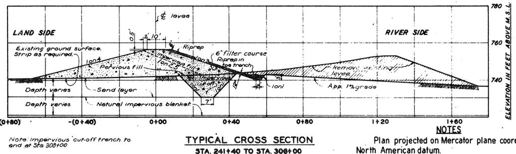
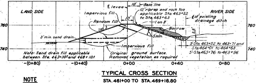
2 CHAPTER A-9 GEOTECHNICAL ANALYSIS NORTH KANSAS CITY LOWER (HARLEM AREA) A-9.1 INTRODUCTION This chapter presents the geotechnical evaluation results for the Harlem area of the North Kansas City - Lower Unit, which was determined to have a high enough probability of failure under the existing level of protection to warrant further study. This determination relies on historical borings and soil test information combined with recent subsurface borings and soil test information. A-9.2 SOURCES OF EXISTING LEVEE DESIGN INFORMATION The primary sources of information for this geotechnical analysis include the references listed in the References section of this chapter. A-9.3 DESCRIPTION OF THE LEVEE UNIT Refer to Section A for a detailed description of the North Kansas City Lower Unit. A-9.4 LEVEE DESIGN FEATURES A Existing Levee and Floodwall Sections The North Kansas Unit is a Federal protection system. It consists of the Airport Section and the Lower Section, as explained by the General chapter of this appendix. The unit was originally constructed as a non-federal levee, but was removed and replaced using Federal standards in The final contract for construction of the project was completed in Upper reach of the Lower Section - The section of the North Kansas City levee known as the Lower Section includes Stations 0+00 to and Stations to The upper reach of the Lower Section consists of a levee section with one stoplog gap. The levee was constructed with a 1V on 3H riverside slope and 1V on 4H landside slope. No underseepage control measures were constructed in the upper reach due to the low height of the levee and thick blanket conditions. Lower reach of the Lower Section - The lower reach consists of a levee section with one sandbag gap and two stoplog gaps. The levee was constructed with a 1V on 4H riverside slope and 1V on 3H landside slope. The underseepage control measure consists of landside seepage berm in open areas. Industry restricted the lateral extent of underseepage berm in the Harlem area (no berm constructed) and the National Starch area (partial berm constructed). Very large berms in excess of 1,000 feet landward of the primary levee toe were constructed between Stations to A plan view of the North Kansas City Unit and typical sections are provided in the Supplemental Exhibits section as Exhibits A-9.1 through A
3 A Future Flood Protection Concerns This levee unit is not recommended for a raise based on the hydraulic analysis of the Missouri and Kansas River flows. During the 1993 flood, Station to Station was reported to have serious flood fighting. Property owners reported excessive water pressures below pavement and building slabs. That pressure resulted in uncontrolled piping of silt foundation blanket materials. Their flood fight efforts consisted of sandbag ring dikes with temporary sand fill placement inside the seepage areas. In one building foundation near National Starch, a standpipe was constructed to offset the excessive head and reduce the piping potential. In another location inside of the National Starch property, sewer piping collapsed resulting in multiple sinkholes inside the protected area. The 1993 flood did not reach the top of levee in these problem areas. A full head to the top of the levee may have lead to catastrophic underseepage failure of this area and all contiguous area inside the North Kansas City protection unit. A Area Site Characterization Boring information provided by Exhibits A-9.8 through A-9.35 supports characterization of the foundation between Station (Broadway Bridge) and Station (Paseo Bridge). The borings were located in the as-built drawings listed in the references. One new boring, AD-1008 (completed in 2001), supplemented the prior borings. The foundation profile has been developed below stations to In subsequent studies, the foundation profile was developed below stations to That reach is discussed in Chapter 10 of this appendix. A Underseepage Analyses Stations to are identified as having underseepage concerns under the interim feasibility portion of the study. The reach from Stations to experienced excessive uplift pressure during the 1993 flood below the existing access road and adjacent structural foundations. The underseepage analysis was modeled after consideration of the types of soils landward of the levee, the consistency of the thickness of the soil blanket clays or silts, the thickness of the sand deposit below the levee blanket materials, the lateral extent of the blanket landside and riverward of the levee, the effects of the location of the Missouri River, and the height of the existing levee. All of these variables were considered during the development of the model to characterize the representative reaches along the alignment of the levee. These reaches were considered separately to determine the landside resistance to upward gradient pressures which could initiate piping of the blanket materials. This could lead to subsequent piping of sand grains toward the river entrance, leading to ultimate collapse of the levee section due to the foundation voids caused by piping. Soil begins moving in the blanket when the pressure change in a vertical column of material exceeds the weight of the material bearing on the location where the pressure change occurs. Because pressure typically decreases from depth to the surface, a diagram of the change in pressure typically produces a sloping line or gradient. The underseepage design aims to assure that the weight of the soil column at any depth exceeds the upward gradient by a safety factor. 9-2
4 The safety factor for checking the materials at the landside toe of the North Kansas City levee is 1.1. An additional design requirement is to provide underseepage control when the safety factor with respect to critical gradient is less than 1.5 with the design water surface 3 feet below the top of levee. Usually the 1.5 safety factor controls the required underseepage design. If the 1.1 safety factor or secondary check of 1.5 is not satisfied, the underseepage control is designed to meet a safety factor of 1.5 for the berm design, the buried collector design, and the pressure relief well design. Berm design was considered only when the area landside of the levee was available for construction. If area for a berm was not available, a buried collector system was considered. In areas that exhibited a blanket thickness of less than 5 feet, relief wells were considered appropriate to provide the underseepage control. The safety factor was set midway between wells to a minimum of 1.5. The pressures at the base of the blanket at the midpoint between wells will reach a maximum, and initiation of soil grain movement will begin at these locations. Permeability parameters were assigned to the blanket materials based on the content of silt, clay or sand. Only areas that contained a blanket thickness of at least ¼ the height of the levee were considered meaningful in the underseepage model. For thin blanket areas, pressure relief wells are considered appropriate for underseepage control. The existing safety factor in the underseepage analysis was calculated using water at the top of levee. The relative magnitude of the permeability ratios of the clean foundation sands to the blanket materials was set after observation of boil activity from the 1951 flood. The Kansas City District method of estimating the underseepage gradient and the required safety factors deviates somewhat from the method presented in the EM The Kansas City District s traditional empirical approach has been used since the 1960 s and has proven effective in providing adequate underseepage control for most reaches within the North Kansas City Unit. This method is based on conclusions of a Corps of Engineers conference, held in Omaha in November, The excellent historical performance of the levees during the 1993 flood event on the Missouri River demonstrates the effectiveness of this procedure. The traditionally assumed permeability ratios for blanket materials are shown in Table A-9.1. TABLE A-9.1 Permeability Ratios for Blanket Materials Blanket Material Assigned Permeability Ratio SM : Silty Sand 100 ML : Silt ML-CL : Silt/Clay 400 CL: Lean Clay CH: Fat Clay
5 The calculations of the underseepage factors of safety that were used in the underseepage analysis are as follows: The gradient piping factor of safety is defined as: FSi = іс / іo where іo = actual gradient and іс = critical gradient іс = γb / γw when soils particles movement can begin at the toe and γb = γsat - γw where γsat = saturated unit weight of the soil and γw = unit weight of water іo = upward gradient through the blanket = change in head from the base of the blanket to the top of the blanket. The reference datum is set at the top of the blanket because the movement of the soil grain will begin at the top of the blanket. h = gradient head calculated at the base of the blanket measure from the reference datum, the top of the blanket. This gradient calculation procedure is provided in the Geotechnical Analysis Existing Conditions chapter of this appendix with defined equations and illustrative nomenclature. zbl = the thickness of the blanket іo = h / zbl then FSi = іс / іo = ( γb / γw ) / ( h / zbl ) = ( γb zbl ) / ( h γw ) The underseepage analysis is provided in Exhibits A-9.36 through A-9.52 in the Supplemental Exhibits section, showing the factor of safety with respect to gradient. Two distinct reaches were characterized, Stations to and Stations to The original designers considered underseepage berms, buried collector, and relief wells for the area being considered. No underseepage control measures were adopted due to marginal safety concerns. The constructed levee section did include a riverside cutoff trench through any unknown upper sand lense layers and a landside sand blanket above the existing ground surface to control any underseepage infiltrating beyond the riverside cutoff trench. The area was to be monitored closely during high water, and future consideration for underseepage control measures were to be based on the monitoring of these reaches. The City of Kansas City, Missouri Water Services Department presented some improvement recommendations for the Harlem area in a 1998 Storm Drainage 9-4
6 Master Plan. That report is included as Exhibit A-9.53 in the Supplemental Exhibits section. Kansas City District underseepage design history indicates that, in areas with very thin to no thickness in blanket materials present, relief wells were the system chosen to control underseepage. The thinnest blanket used in the analysis was 5 feet. It is expected that the blanket thickness will vary from 5 to 10 feet. Alternate underseepage control measures were considered for Stations to The underseepage controls considered were flood fighting, underseepage berms, buried collector system, and pressure relief wells. The alternatives vary with respect to the methodology to remove the underseepage water. The preliminary design does not require evacuation of the underseepage water in order to keep the levee from failing. The interior will flood due to underseepage flow containment in the Harlem area. As a minimum design consideration, the flows from the wells or buried collector system can be collected in manholes during high water. The sponsors will be responsible for setting up portable pumps and discharges lines to dispose of the underseepage water back to the river source by carrying the flow up and over the levee through temporary piping systems (also provided by the sponsor). The recommended pumping facilities requirements are discussed in the Civil Design chapter of this appendix. The present recommended plan for controlling underseepage and reducing the uplift at the toe of the levee, Stations to is a buried collector system. A Reassessment of Existing Risk and Uncertainty The existing conditions analysis (refer to Geotechnical Anaylsis Existing Conditions chapter) was provided as a limited initial evaluation of the North Kansas City Unit s underseepage risk. This chapter indicates that the Harlem area is an area of concern based on recent discovery of the flood fighting efforts inside of levee Stations to An additional risk and uncertainty analysis is provided for the specified stations in the next chapter. Additional characterization of the reach from Stations to has resulted in a revised risk and uncertainty for that reach. The results are provided for consideration in Table A
7 TABLE A-9.2 Existing Conditions Risk and Uncertainty Results Height of Water on Levee, feet Station to Probability of Unsatisfactory Performance (1993) (top of levee) The assessment of the existing conditions includes observations that led to the selection of a satisfactory performance with respect to underseepage using a factor of safety of 0.7. Historical observations concluded that a factor of safety of 0.55 represents impending failure of the toe of the levee. The observations in 1993 did not lead to total failure of the levee toe for the level of water on the levee. The levee from Stations to experienced large uplift forces, while the levee from Stations to included flood fighting to save the foundation of an existing processing building (landside of the toe in excess of 500 feet). ETL indicates the use of a factor of 1.0 in the underseepage analysis. The North Kansas City levee experienced a factor of safety lower than 1.0 and did not fail for that water level during the flood of The observations and calculations indicate a factor of safety near 0.7 may be representative. A higher river level most likely would result in an even lower factor of safety. For a factor of safety of 0.7, the probability of a catastrophic underseepage failure was calculated to be greater than 60% for Stations to A buried collector system is recommended for Stations to The system is to be designed in accordance with Corps of Engineers manuals in order to strengthen the weak sections of the levee and eliminate the serious risk of underseepage failure. 9-6
8 A-9.5 REFERENCES 1. North Kansas City Levee Unit, Definite Project Report, December North Kansas City Levee Unit, Analysis of Design, Levee and Floodwall, May North Kansas City Levee Unit, Supplement on Interior Drainage, June North Kansas City Levee Unit, Supplement on Seepage Control, January North Kansas City Levee Unit, Supplement on Interior Drainage, May North Kansas City Levee Unit, Record Drawings for Levee, Floodwall and Appurtenances, December North Kansas City Levee Unit, Analysis of Design - Burlington Pump Plant, January North Kansas City Levee Unit, Analysis of Design Howell Pump Plant, January North Kansas City Levee Unit, Analysis of Design Rock Creek Pump Plant, April North Kansas City Levee Unit, Supplement on Interior Drainage, June North Kansas City Levee Unit, Record Drawings Structures, Appendix I, May North Kansas City Levee Unit, Record Drawings, Pump Plants, Appendix IV, July North Kansas City Levee Unit, Analysis of Design Station Pump Plant, October North Kansas City Levee Unit Periodic General Inspection No. 1, July North Kansas City Levee Unit, Periodic General Inspection No. 2, March North Kansas City Levee Unit, Operations and Maintenance Manual Volume I, January
9 17. North Kansas City Levee Unit, Operations and Maintenance Manual Volume II, January Geotechnical Engineering Report for National Starch & Chemical Company, Packing Line #3 and Blending Bin Expansion Project, North Kansas City, Missouri, February 24, Modified Version, NKC, Fall 1993, Vol 5, No. 4, National Starch Information Pamphlet. 20. The C.W. Mofsinger Company Letter to Mr. Don Janiak, Plant Supervisor, National Starch and Chemical Company, Regarding Adhesive Loading Pit Inspection, August 10, 1993, 2 pages. 21. The C.W. Mofsinger Company Letter to Mr. Louis J. Jones, Mechanical Supervisor, National Starch and Chemical Company, August 10, 1993, 5 pages. 22. The C.W. Mofsinger Company Letter to Mr. Don Janiak, Mechanical Supervisor, National Starch and Chemical Company, Regarding Adhesive Building Joint Inspection, August 10, 1993, 2 pages. 23. The C.W. Mofsinger Company Letter to Mr. Fred Kidd, Construction & Utilities Supervisor, National Starch and Chemical Company, Regarding Structural Concerns at National Starch, August 9, 1993, 6 pages. 9-8
10 A-9.6 SUPPLEMENTAL EXHIBITS 9-9

11 EXHIBIT A

12 EXHIBIT A

13 EXHIBIT A
14 EXHIBIT A

15 EXHIBIT A

16 EXHIBIT A

17 EXHIBIT A
18 Site Characterization Maps and Boring Information 9-17
19 EXHIBIT A
20 EXHIBIT A
21 EXHIBIT A

22 EXHIBIT A

23 EXHIBIT A
24 EXHIBIT A

25 EXHIBIT A

26 EXHIBIT A
27 EXHIBIT A
28 EXHIBIT A
29 EXHIBIT A
30 EXHIBIT A

31 EXHIBIT A
32 EXHIBIT A

33 EXHIBIT A

34 EXHIBIT A
35 EXHIBIT A

36 EXHIBIT A
37 EXHIBIT A

38 EXHIBIT A
39 EXHIBIT A
40 EXHIBIT A
41 EXHIBIT A
42 EXHIBIT A
43 EXHIBIT A
44 EXHIBIT A

45 EXHIBIT A

46 EXHIBIT A
47 Geotechnical Calculations 9-46
48 EXHIBIT A
49 EXHIBIT A-9.37 Underseepage Berm Design for the Harlem Section North Kansas City Levee Unit Station to Written By: Stefanie Voss Date: October 24, 2003 The Kansas City District underseepage design practice is based on a developed criteria somewhat varying from the USACE EM. The KCD model uses permeability ratios of foundation to blanket thickness based on less conservative assumptions than the USACE model in the EM. This judgment was based service records form the 1951 and 1993 flood experience on existing Kansas City levees. Before using the spreadsheet established for berm design, hand calculations were performed for the designer to become familiar with the design formulas for underseepage berm requirements. For the Harlem area, stations to , the blanket was assigned a thickness of 10 feet and permeability ratio of 300. Once the underseepage design was calculated by hand, the same numbers were entered into the Excel spreadsheet. The spreadsheet results were compared to the hand calculations, which mostly matched. Any differences were attributed to rounding of the results in the spreadsheet or formulas. The next calculations considered a thinner blanket based on the review of existing cross-sections. Stations to were considered to have blanket material thinner than 10 feet. This reach was modeled using a thickness of 5 feet. This reflected the only change in the numbers for calculation. Factors of Safety were lower than the required 1.1 and 1.5 for full and reduced head respectively. To compensate, a berm of greater thickness and width was assigned. The width was extended to 350 feet to achieve a Berm Toe Factor of Safety to 1.1. A berm thickness of 4.2 feet was required to meet the factor of safety of 1.5 at the primary levee toe. A required minimum 5 feet thick berm was assigned. This is required in EM , design and Construction of Levees, dated 20 April The spreadsheet results were compared to land use maps and aerial photographs to determine the berm alternative cost. While the thickness of the blanket is modeled as uniform in the existing as built records of the cross section through the levee, the thickness appears to decrease, as it gets closer to the Heart of America Bridge. One of the borings, DH-216, was shown as 150 feet landside away from the crown of the levee. Additional subsurface information should be obtained during PED to further refine the underseepage berm limits. At this time conservative lengths of berms will be used for the development of quantities for the berm alternative. 9-48
50 EXHIBIT A
51 EXHIBIT A
52 EXHIBIT A
53 EXHIBIT A

54 EXHIBIT A
55 EXHIBIT A
56 EXHIBIT A-9.44 Existing Conditions 9-55
57 EXHIBIT A
58 EXHIBIT A
59 EXHIBIT A
60 EXHIBIT A
61 EXHIBIT A
62 EXHIBIT A
63 EXHIBIT A

64 EXHIBIT A-9.52 Missouri River Existing Conditions Water Surface Elevations 9-63
65 EXHIBIT A-9.53 NOTE: THIS REPORT WAS DONE FOR THE KANSAS CITY, MO WATER SERVICES DEPARTMENT IT WAS NOT DONE AS PART OF THE COE FEASIBILITY STUDY. PHASE 1, PHASE 2, AND NORTHEAST INDUSTRIAL DISTRICT DESIGNATIONS AS PRESENTED IN THIS EXHIBIT ARE VALID FOR THIS EXHIBIT ONLY. 9-64
66 9-65
67 9-66
68 9-67
69 9-68
Chapter A-10 GEOTECHNICAL ANALYSIS NORTH KANSAS CITY - LOWER (NATIONAL STARCH AREA)
") Kansas Citys, Missouri and Kansas Flood Damage Reduction Feasibility Study (Section 216 Review of Completed Civil Works Projects) Engineering Appendix to the Interim Feasibility Report Chapter A-10 GEOTECHNICAL
Kansas Citys, Missouri and Kansas Flood Damage Reduction Feasibility Study (Section 216 Review of Completed Civil Works Projects) Engineering Appendix to the Interim Feasibility Report Chapter A-10 GEOTECHNICAL
Chapter A-8 GEOTECHNICAL ANALYSIS FAIRFAX-JERSEY CREEK (JERSEY CREEK SHEET PILE WALL)
") Kansas Citys, Missouri and Kansas Flood Damage Reduction Feasibility Study (Section 216 Review of Completed Civil Works Projects) Engineering Appendix to the Interim Feasibility Report Chapter A-8 GEOTECHNICAL
Kansas Citys, Missouri and Kansas Flood Damage Reduction Feasibility Study (Section 216 Review of Completed Civil Works Projects) Engineering Appendix to the Interim Feasibility Report Chapter A-8 GEOTECHNICAL
APPENDIX F VALUE ENGINEERING
 U.S. Army Corps of Engineers, Kansas City District Final Feasibility Report APPENDIX F VALUE ENGINEERING Kansas Citys, Missouri and Kansas Flood Risk Management Project Final Feasibility Report THIS PAGE
Chapter A-17 CONSTRUCTION PROCEDURES AND WATER CONTROL PLAN
 Kansas Citys, Missouri and Kansas Flood Damage Reduction Feasibility Study (Section 216 Review of Completed Civil Works Projects) Engineering Appendix to the Interim Feasibility Report Chapter A-17 CONSTRUCTION
Chapter A-15. CID-MO Structural Analysis
 Kansas Citys, Missouri and Kansas Flood Risk Management Feasibility Study Engineering Appendix to the Final Feasibility Study Chapter A-15 CID-MO Structural Analysis Chapter A-15 CID-MO Structural Analysis
Flood Fighting and Surveillance
 Flood Fighting and Surveillance Don Moses Civil Engineer February 2016 US Army Corps of Engineers 1 Agenda Levee Design Common Failure Modes Surveillance/Inspection Flood Fighting 2 Levee Design Issues
Chapter A-13 STRUCTURAL ANALYSIS ARGENTINE RAISE
 Kansas Citys, Missouri and Kansas Flood Damage Reduction Feasibility Study (Section 216 Review of Completed Civil Works Projects) Engineering Appendix to the Interim Feasibility Report Chapter A-13 STRUCTURAL
Regulation 18 August 2009 NO Operations and Maintenance LEVEE ENCROACHMENT STANDARDS AND PROCEDURES
 CENWP-EC DEPARTMENT OF THE ARMY PDR 30-2-5 Portland District, Corps of Engineers (Draft) P.O. Box 2946 Portland, Oregon 97208 Regulation 8 August 2009 NO. 30-2-5 Operations and Maintenance LEVEE ENCROACHMENT
Regional Vegetation Variance
 Paige Caldwell, P.E. Emergency Manager Overview Key points from the ETL guidance Vegetation variance authority and background Key points of variance guidance Next Steps Key points from the newly revised
CONSTRUCTION PLAN CHECKLIST
 CONSTRUCTION PLAN CHECKLIST The design engineer is responsible for ensuring that plans submitted for city review are in accordance with this checklist. It is requested that the executed checklist be submitted
REVISED ETL Guidelines for Landscaping and Vegetation Management
 REVISED ETL 1110-2-571 Guidelines for Landscaping and Vegetation Management Paige Caldwell, P.E. Emergency Manager Overview Policy revision process Key points from the ETL guidance Illustrations of acceptable
Lower San Joaquin River Feasibility Study PLAN FORMULATION ADDENDUM
 PLAN FORMULATION ADDENDUM Non-Structural Measure Descriptions Elevate Critical Infrastructure This measure would raise at-risk critical structures above the design inundation level. Elevation would be
Civil Engineer USACE, Omaha District. 28 February 2017 FLOOD FIGHTING AND SURVEILLANCE
 217 FLOOD FIGHTING AND SURVEILLANCE 237 200 237 217 200 Don Moses, 237 P.E. 217 200 Civil Engineer USACE, Omaha District 255 0 163 131 255 0 163 132 255 0 163 122 28 February 2017 239 65 53 80 119 27 110
Kansas Citys, Missouri and Kansas Flood Risk Management Project Final Feasibility Report
 US Army Corps of Engineers Kansas City District Northwestern Division Kansas Citys, Missouri and Kansas May 2014 THIS PAGE INTENTIONALLY LEFT BLANK Kansas Citys, Kansas and Missouri May 2014 Table of Contents
UPPER MISSISSIPPI RIVER COMPREHENSIVE PLAN
 UPPER MISSISSIPPI RIVER COMPREHENSIVE PLAN APPENDIX D COST ESTIMATES Prepared by the U.S. Army Corps of Engineers Rock Island, St. Louis, and St. Paul Districts March 2008 UPPER MISSISSIPPI RIVER COMPREHENSIVE
ENGINEERING REPORT STRUCTURAL STABILITY ANALYSIS FLOODWALLS. HOUSATONIC RIVER and NAUGATUCK RIVER FLOOD PROTECTION PROJECTS SECTION 1
 ENGINEERING REPORT STRUCTURAL STABILITY ANALYSIS FLOODWALLS HOUSATONIC RIVER and NAUGATUCK RIVER FLOOD PROTECTION PROJECTS SECTION 1 ANSONIA and DERBY, CONNECTICUT December 2010 MMI #1560-119 and #3118-03
INDIAN BEND WASH 2 LEVEE SYSTEM MARICOPA COUNTY, ARIZONA NLD SYSTEM ID #
 INDIAN BEND WASH 2 LEVEE SYSTEM MARICOPA COUNTY, ARIZONA NLD SYSTEM ID # 3805020008 PERIODIC INSPECTION REPORT NO. 1 GENERALIZED EXECUTIVE SUMMARY FINAL SYSTEM RATING: MINIMALLY ACCEPTABLE FINAL RATING
PROJECT REVIEW PLAN TOPEKA, KANSAS FLOOD RISK MANAGEMENT PROJECT PRE-CONSTRUCTION ENGINEERING AND DESIGN PHASE
 PROJECT REVIEW PLAN TOPEKA, KANSAS FLOOD RISK MANAGEMENT PROJECT PRE-CONSTRUCTION ENGINEERING AND DESIGN PHASE NOVEMBER 2010 THIS PAGE INTENTIONALLY LEFT BLANK PROJECT REVIEW PLAN TOPEKA, KANSAS, FLOOD
Chapter A-12 STRUCTURAL ANALYSIS EXISTING CONDITIONS
 Kansas Citys, Missouri and Kansas Flood Damage Reduction Feasibility Study (Section 216 Review of Completed Civil Works Projects) Engineering Appendix to the Interim Feasibility Report Chapter A-12 STRUCTURAL
CHAPTER 8 SEEPAGE CONTROL IN EMBANKMENTS
 CHAPTER 8 SEEPAGE CONTROL IN EMBANKMENTS 8-1. General. All earth and rock-fill dams are subject to seepage through the embankment, foundation, and abutments. Seepage control is necessary to prevent excessive
Chapter A-14 CID-KS STRUCTURAL ANALYSIS
 Kansas Citys, Missouri and Kansas Flood Risk Management Study to the Final Feasibility Report Chapter A-14 CID-KS STRUCTURAL ANALYSIS Chapter A-14 CID-KS Structural Analysis Table of Contents A-14.1 Overview...
Effective Stress Design For Floodwalls on Deep Foundations
 Effective Stress Design For Floodwalls on Deep Foundations Glen Bellew, PE Geotechnical Engineer USACE-Kansas City 23 April 2015 Contributors James Mehnert, PE USACE-Kansas City Paul Axtell, PE, D.GE Dan
Distribution Restriction Statement
 DEPARTMENT OF THE ARMY U.S. Army Corps of Engineers CECW-EG Washington, DC 20314-1000 Technical Letter No. 1110-2-555 30 November 1997 Engineering and Design DESIGN GUIDANCE ON LEVEES Distribution Restriction
Manhattan Levee Section 216 Feasibility Study Public Workshop 17Apr13 Manhattan Kansas
 Manhattan Levee Section 216 Feasibility Study Public Workshop 17Apr13 Manhattan Kansas Tuttle Creek Dam and Lake Kansas City District Project Development Team Manhattan, KS US Army Corps of Engineers 1
DRAFT 2 ND SUPPLEMENTAL ENVIRONMENTAL ASSESSMENT WITH DRAFT FINDING OF NO SIGNIFICANT IMPACT
 DRAFT 2 ND SUPPLEMENTAL ENVIRONMENTAL ASSESSMENT WITH DRAFT FINDING OF NO SIGNIFICANT IMPACT MELVIN PRICE REACH OF WOOD RIVER LEVEE UNDERSEEPAGE DESIGN DEFICIENCY CORRECTIONS PROJECT SUPPLEMENTAL REPORT
(b) The written request must include 5 components: 1 The Permit Review and Approval Process. (1) Step 1: Pre-Coordination.
 The written request must include 5 components: 1 The Permit Review and Approval Process. (1) Step 1: Pre-Coordination.") 1 The Permit Review and Approval Process The processing of a Section 408 Permit request begins with a written request from an applicant. Along with the written request, a permit application (attached)
1 The Permit Review and Approval Process The processing of a Section 408 Permit request begins with a written request from an applicant. Along with the written request, a permit application (attached)
SAN LUIS REY RIVER 3 LEVEE SYSTEM SAN DIEGO COUNTY, CALIFORNIA NLD SYSTEM ID #
 SAN DIEGO COUNTY, CALIFORNIA NLD SYSTEM ID # 3805010012 PERIODIC INSPECTION REPORT NO. 1 GENERALIZED EXECUTIVE SUMMARY FINAL SYSTEM RATING: UNACCEPTABLE FINAL RATING DATE: DECEMBER 15, 2017 PERIODIC INSPECTION
Distribution Restriction Statement Approved for public release; distribution is unlimited.
 CECW-EG Engineer Regulation 1110-2-1942 Department of the Army U.S. Army Corps of Engineers Washington, DC 20314-1000 Engineering and Design INSPECTION, MONITORING AND MAINTENANCE OF RELIEF WELLS 25 September
Evaluation of Cutoff Walls Impact on Groundwater Recharge (Kleinfelder)
") C3 Evaluation of Cutoff Walls Impact on Groundwater Recharge (Kleinfelder) December 19, 2007 Revised April 21, 2009 File No.: 72834 Mr. Timothy Washburn SAFCA 1007 7th Street, 7th Floor Sacramento, CA
C3 Evaluation of Cutoff Walls Impact on Groundwater Recharge (Kleinfelder) December 19, 2007 Revised April 21, 2009 File No.: 72834 Mr. Timothy Washburn SAFCA 1007 7th Street, 7th Floor Sacramento, CA
SANTA ANA RIVER/ SAN TIMOTEO CREEK 1 LEVEE SYSTEM SAN BERNARDINO COUNTY, CALIFORNIA NLD SYSTEM ID #
 SANTA ANA RIVER/ SAN TIMOTEO CREEK 1 LEVEE SYSTEM SAN BERNARDINO COUNTY, CALIFORNIA NLD SYSTEM ID # 3805030015 PERIODIC INSPECTION REPORT NO. 1 GENERALIZED EXECUTIVE SUMMARY FINAL SYSTEM RATING: UNACCEPTABLE
In preparation for constructing buildings on a property, the builder. Site Preparation CHAPTER
 CHAPTER 3 Site Preparation In preparation for constructing buildings on a property, the builder must consider a number of factors related to code requirements. The buildings must be located according to
SECTION TRENCHING
 SECTION 31 23 17 TRENCHING PART 1 GENERAL 1.1 SUMMARY A. Section Includes: 1. Excavating trenches for utilities and utility structures. 2. Bedding. 3. Backfilling and compacting to subgrade elevations.
GEOTECHNICAL INVESTIGATION PROPOSED OUTFALL LOCATION CITY OF MORGAN S POINT DRAINAGE HARRIS COUNTY, TEXAS REPORT NO
 GEOTECHNICAL INVESTIGATION PROPOSED OUTFALL LOCATION CITY OF MORGAN S POINT DRAINAGE HARRIS COUNTY, TEXAS REPORT NO. 1140198001 Reported to: SIRRUS ENGINEERS, INC. Houston, Texas Submitted by: GEOTEST
An Introduction to Seepage, Slope and Settlement of Levees
 An Introduction to Seepage, Slope and Settlement of Levees Course No: G02-011 Credit: 2 PDH J. Paul Guyer, P.E., R.A., Fellow ASCE, Fellow AEI Continuing Education and Development, Inc. 9 Greyridge Farm
Determination of Design Infiltration Rates for the Sizing of Infiltration based Green Infrastructure Facilities
 Determination of Design Infiltration Rates for the Sizing of Infiltration based Green Infrastructure Facilities 1 Introduction This document, developed by the San Francisco Public Utilities Commission
AGUA FRIA RIVER 5 LEVEE SYSTEM MARICOPA COUNTY, ARIZONA NLD SYSTEM ID #
 AGUA FRIA RIVER 5 LEVEE SYSTEM MARICOPA COUNTY, ARIZONA NLD SYSTEM ID # 3805020001 PERIODIC INSPECTION REPORT NO. 1 GENERALIZED EXECUTIVE SUMMARY FINAL SYSTEM RATING: MINIMALLY ACCEPTABLE FINAL RATING
Utah State University
 Utah State University GIS in Water Resources CEE 6440 Dr. David Tarboton Underseepage Analysis in levees using GIS Prepared by Lourdes Polanco December, 2012 Introduction Levees are embankments designed
Levee Cutoff Wall Construction Considerations Natomas Levee Improvement Program July 28, 2009
 Levee Cutoff Wall Construction Considerations Natomas Levee Improvement Program Background The Natomas Levee Improvement Program (NLIP), sponsored by the Sacramento Area Flood Control Agency (SAFCA) with
 Appendix B Example of the Tiered NEPA Document to be used for Categorically Permitted Alterations PROGRAMMATIC ENVIRONMENTAL ASSESSMENT CATEGORICAL PERMISSIONS SECTION 408 ALTERATIONS TO EXISTING U.S.
LOS ANGELES RIVER/ COMPTON CREEK 2 LEVEE SYSTEM LOS ANGELES COUNTY, CALIFORNIA NLD SYSTEM ID #
 LOS ANGELES RIVER/ COMPTON CREEK 2 LEVEE SYSTEM LOS ANGELES COUNTY, CALIFORNIA NLD SYSTEM ID # 3805010033 PERIODIC INSPECTION REPORT NO. 2 GENERALIZED EXECUTIVE SUMMARY FINAL SYSTEM RATING: UNACCEPTABLE
SAN GABRIEL RIVER/SAN JOSE CREEK 1 LEVEE SYSTEM LOS ANGELES COUNTY, CALIFORNIA NLD SYSTEM ID #
 SAN GABRIEL RIVER/SAN JOSE CREEK 1 LEVEE SYSTEM LOS ANGELES COUNTY, CALIFORNIA NLD SYSTEM ID # 3805010052 PERIODIC INSPECTION REPORT NO 1 GENERALIZED EXECUTIVE SUMMARY FINAL SYSTEM RATING: MINIMALLY ACCEPTABLE
Geotechnical Evaluation of a Small Levee System for FEMA Certification. Rebecca Money, PE, GE, CFM
 Geotechnical Evaluation of a Small Levee System for FEMA Certification Rebecca Money, PE, GE, CFM Purpose Provide an overview and an understanding for Cities/Counties/Districts of what it takes from a
 Tiered NEPA Document for Categorically Permitted Alterations to Existing U.S. Army Corps of Engineer Civil Works Projects Proposed Categorically Permitted Alterations (Check all that apply) Utilities under
ENGINEERING AND CONSTRUCTION BULLETIN
 ENGINEERING AND CONSTRUCTION BULLETIN No. 2017-15 Issuing Office: CECW-CE Issued: 14 Jul 17 Expires: 14 Jul 19 SUBJECT: Managed Overtopping of Levee Systems CATEGORY: Guidance APPLICABILITY: The U.S. Army
Distribution Restriction Statement Approved for public release; distribution is unlimited.
 CECW-ED Regulation No. 1110-2-8152 Department of the Army U.S. Army Corps of Engineers Washington, DC 20314-1000 Engineering and Design PLANNING AND DESIGN OF TEMPORARY COFFERDAMS AND BRACED EXCAVATIONS
 Risk Assessment of Proposed Remediation Methods Trinity River Corridor Dallas Floodway 2 November 2012 Table of Contents Introduction... 1 Alternatives Analysis Risk Assessment... 1 Project Authorization...
Final Compiled Comments and Responses. on the. IEPR of the Melvin Price Wood River LRR
 Final Compiled Comments and Responses on the IEPR of the Melvin Price Wood River LRR Comment 1: The performance metrics and alternative screening process are not presented in sufficient detail to justify
B. Borrow: Satisfactory soil imported from off-site for use as fill or backfill.
 SECTION 312000- EARTHWORK PART 1 - GENERAL 1.1 RELATED DOCUMENTS Drawings and general provisions of the Contract, including General and Special Conditions, apply to this Section. 1.2 SUMMARY This Section
DAM SAFETY Chena River Lakes Flood Control Project U.S. Army Corps of Engineers, Alaska District
 DAM SAFETY Chena River Lakes Flood Control Project U.S. Army Corps of Engineers, Alaska District COL Reinhard Koenig, PE Commander, USACE Alaska District Patricia S. Opheen, PE Chief, Engineering Division
Preliminary Concepts for Soil-Bentonite Cutoff Wall Topock Compressor Station, Needles, California
 TECHNICAL MEMORANDUM Preliminary Concepts for Soil-Bentonite Cutoff Wall Topock Compressor Station, Needles, California DATE: April 14, 2004 Pacific Gas and Electric Company (PG&E) is undertaking an expedited
Geotechnical and Structures. Laboratory. Performance of Levee Underseepage Controls: A Critical Review ERDC/GSL TR-02-19
 ERDC/GSL TR-02-19 Performance of Levee Underseepage Controls: A Critical Review Thomas F. Wolff September 2002 Geotechnical and Structures Laboratory Approved for public release; distribution is unlimited.
The Vegetation Challenge Sacramento, California August 28-29, 29, 2007
 The Vegetation Challenge Sacramento, California August 28-29, 29, 2007 David A. Pezza, P. E. U. S. Army Corps, Headquarters Engineering and Construction Chief, Civil Works Branch ASCE Civil Engineering
USACE LEVEE RISK ASSESSMENT PROCESS LESSONS LEARNED
 USACE LEVEE RISK ASSESSMENT PROCESS LESSONS LEARNED 1 237 237 237 217 217 217 200 200 200 80 119 27 252 174.59 255 255 255 0 0 0 163 163 163 131 132 122 239 65 53 110 135 120 112 92 56 62 102 130 102 56
Technical Memorandum No. 8 June 3, 2013 Page 2. FEMA Floodplain Mapping Flood Elevations at WWTP
 Page 2 FEMA Floodplain Mapping Flood Elevations at WWTP Existing Flood Control Facilities The City of Davis WWTP is located immediately north of the Willow Slough Bypass and west of the Yolo Bypass (see
Maintaining Your Levee
 Maintaining Your Levee North Kansas City Levee District Case Study Leon J. Staab, P.E. KC Urban Stormwater Conference January 23, 2016 I n t r o d u c t i o n North Kansas City Levee Unit Constructed in
2015 LANDFILL INSPECTION REPORT CARDINAL PLANT BRILLIANT, OHIO
 2015 LANDFILL INSPECTION REPORT GERS-15-021 CARDINAL PLANT BRILLIANT, OHIO PREPARED BY GEOTECHNICAL ENGINEERING AEP SERVICE CORPORATION 1 RIVERSIDE PLAZA COLUMBUS, OHIO Cardinal Plant Landfill Inspection
Prince George s County, MD Levee Response and Remediation Plan
 Prince George s County, MD Levee Response and Remediation Plan Presented By: Hilary Stephens-Kendro Prepared for: Prince George s County Department of Public Works and Transportation Project Background
CONSTRUCTION COST ESTIMATE FOR SOUTHWESTERN ILLINOIS LEVEE CERTIFICATION DESIGN IMPROVEMENTS
 CONSTRUCTION COST ESTIMATE FOR SOUTHWESTERN ILLINOIS LEVEE CERTIFICATION DESIGN IMPROVEMENTS PREPARED FOR SOUTHWESTERN ILLINOIS FLOOD PREVENTION DISTRICT COUNCIL PREPARED BY AMEC EARTH & ENVIRONMENTAL,
TECHNICAL MEMORANDUM
 TECHNICAL MEMORANDUM SOIL SAMPLING, TESTING AND LOGGING ULOP GEOTECHNICAL EVALUATION STAR BEND SETBACK LEVEE Sutter County, California Prepared by: BLACKBURN CONSULTING 2491 Boatman Avenue West Sacramento,
LOS ANGELES RIVER/COMPTON CREEK 2 LEVEE SYSTEM LOS ANGELES COUNTY, CALIFORNIA NLD SYSTEM ID #
 LOS ANGELES RIVER/COMPTON CREEK 2 LEVEE SYSTEM LOS ANGELES COUNTY, CALIFORNIA NLD SYSTEM ID # 3805010033 PERIODIC INSPECTION REPORT NO 1 GENERALIZED EXECUTIVE SUMMARY FINAL SYSTEM RATING: UNACCEPTABLE
2. City of Seattle Supplement to the Specification for Road, Bridge and Municipal Construction, most current addition.
 Design Guide Basis of Design This section applies to the design and installation of earthwork and backfill. Design Criteria No stockpiling of excavation materials is allowed unless the Geotechnical Engineer
MILL CREEK LEVEE SYSTEM SAN BERNARDINO COUNTY, CALIFORNIA NLD SYSTEM ID #
 SAN BERNARDINO COUNTY, CALIFORNIA NLD SYSTEM ID # 3805010056 PERIODIC INSPECTION REPORT NO 1 GENERALIZED EXECUTIVE SUMMARY FINAL SYSTEM RATING: MINIMALLY ACCEPTABLE FINAL RATING DATE: SEPTEMBER 23, 2013
SAN GABRIEL RIVER 1 LEVEE SYSTEM LOS ANGELES COUNTY, CALIFORNIA NLD SYSTEM ID #
 LOS ANGELES COUNTY, CALIFORNIA NLD SYSTEM ID # 3805010031 PERIODIC INSPECTION REPORT NO. 2 GENERALIZED EXECUTIVE SUMMARY FINAL SYSTEM RATING: MINIMALLY ACCEPTABLE FINAL RATING DATE: APRIL 19, 2017 PERIODIC
Southeast Louisiana Flood Protection Authority - East Levee Safety Permit Policy. Revised November 17, 2017
 Southeast Louisiana Flood Protection Authority - East Levee Safety Permit Policy Revised November 17, 2017 A. Background. Levee districts and Flood Authorities, as sponsors of most federally authorized
STRUCTURAL STABILITY ASSESSMENT
 STRUCTURAL STABILITY ASSESSMENT CFR 257.73(d) East and West Bottom Ash Pond Pirkey Plant Hallsville, Texas October, 2016 Prepared for: Southwest Electric Power Company (SWEPCO) - Pirkey Plant Hallsville,
John Remus Assessment of Conceptual Nonstructural Alternative
 John Remus Assessment of Conceptual Nonstructural Alternative Assessment of Conceptual Nonstructural Alternative Levee Setbacks along the Missouri River (Lower L-575 / Upper L-550 and Lower L-550) Missouri
406 - PIPE SEWERS - MTC FORM 406
 406 - - MTC FORM 406 INDEX 406.1 GENERAL Types of Pipe Pipe Strength, Rigid Pipes Polyethylene Pipe Strength - Rigid or Flexible Pipe Strength and Treatment, Flexible Pipes Selection of Type, Strength
NOTICE OF PREPARATION
 NOTICE OF PREPARATION Date: June 12, 2014 To: From: Subject: Governor s Office of Planning and Research/State Clearinghouse Unit, Responsible Agencies, Trustee Agencies, and Interested Parties Announcement
Data Collection Report draft
 Data Collection Report draft City of Houston, Minnesota Houston Levee Certification Phase I Report prepared by June 2, 2015 DATA COLLECTION REPORT PHASE I DATA COLLECTION AND REVIEW HOUSTON LEVEE CERTIFICATION
HURRICANE SANDY LIMITED REEVALUATION REPORT UNION BEACH, NEW JERSEY DRAFT ENGINEERING APPENDIX SUB APPENDIX B-2 FLOODWALL PILE ANALYSES EAST WALLS
 HURRICANE SANDY LIMITED REEVALUATION REPORT UNION BEACH, NEW JERSEY DRAFT ENGINEERING APPENDIX SUB APPENDIX B-2 FLOODWALL PILE ANALYSES EAST WALLS Revised March 2015 Preliminary Flood Wall Pile Analysis
APPENDIX CENTRAL CITY CLEAR FORK / WEST FORK TRINITY RIVER, AND MARINE CREEK FEASIBILITY STUDY
 APPENDIX CENTRAL CITY CLEAR FORK / WEST FORK TRINITY RIVER, AND MARINE CREEK FEASIBILITY STUDY GENERAL CIVIL DESIGN The purpose of this appendix is to provide feasibility level engineering information
LEVEE DISTRICT NO. 1 OF SUTTER COUNTY
 LEVEE DISTRICT NO. 1 OF SUTTER COUNTY STAR BEND SETBACK LEVEE AND HABITAT ENHANCEMENT PROJECT BASIS OF DESIGN FEBRUARY 2009 Prepared By: TABLE OF CONTENTS QUALITY CONTROL CERTIFICATION... iv 1.0 INTRODUCTION...
Standards for Soil Erosion and Sediment Control in New Jersey May 2012 STANDARD FOR SLOPE PROTECTION STRUCTURES. Definition
 STANDARD FOR SLOPE PROTECTION STRUCTURES Definition Structures to safely conduct surface runoff from the top of a slope to the bottom of the slope. Purpose The purpose of this practice is to convey storm
An Introduction to Road Design for Cold Regions
 An Introduction to Road Design for Cold Regions J. Paul Guyer 2013 1 CONTENTS 1. GENERAL 2. BASE COURSE AND PAVEMENT COMPOSITION 3. BASE COURSE DESIGN IN AREAS OF NON-FROST- SUSCEPTIBLE SOILS 4. BASE COURSE
DRAINAGE & DESIGN OF DRAINAGE SYSTEM
 Drainage on Highways DRAINAGE & DESIGN OF DRAINAGE SYSTEM P. R.D. Fernando Chartered Engineer B.Sc.(Hons), M.Eng. C.Eng., MIE(SL) Drainage Requirement of Highway Drainage System Introduction Drainage means
By Roger Churchwell San Joaquin Area Flood Control Agency.
 By Roger Churchwell San Joaquin Area Flood Control Agency www.sjafca.com Urban flood control facilities have preformed over the last 59 years Locally we are at the bottom of the bathtub Nearly 500,000
SECTION SOILS REPORT
 SECTION 02300 SOILS REPORT 1. GENERAL: 1.1 All work included under this heading shall be subject to the General Conditions of the entire operation. This Contractor is required to refer especially thereto.
Category 1 Waste Rock Stockpile Groundwater Containment System
 Memorandum To: Jennifer Saran, Poly Met Mining Inc. Project: 23690862.00-042-008 1.0 Introduction The Co-Lead Agencies have requested a summary of the four containment systems that are planned for the
ARKANSAS & LOUISIANA LEVEE AND DRAINAGE DISTRICTS MEETINGS
 ARKANSAS & LOUISIANA LEVEE AND DRAINAGE DISTRICTS MEETINGS Rodney Nordby Vicksburg District Red River Projects Office Bossier City, LA. 25-26 January 2017 AGENDA - Types of Inspections - Levee Maintenance
M E M O R A N D U M. 1. PSOMAS position on vertical datum differences between NGVD29 and NAVD88 for the NLIP project (submitted by Brian Bullock:
 M E M O R A N D U M Date: August 5, 2009 Prepared by: SAFCA NLIP Consultants Purpose: Response to the request by the Board of Senior Consultants (BOSC) in Board Report No. 1; Initial Recommendations Following
2016 LANDFILL INSPECTION REPORT CARDINAL PLANT BRILLIANT, OHIO
 2016 LANDFILL INSPECTION REPORT GERS-16-004 CARDINAL PLANT BRILLIANT, OHIO PREPARED BY GEOTECHNICAL ENGINEERING AEP SERVICE CORPORATION 1 RIVERSIDE PLAZA COLUMBUS, OHIO Cardinal Plant Landfill Inspection
Created by Simpo PDF Creator Pro (unregistered version) Asst.Prof.Dr. Jaafar S. Maatooq
 Asst.Prof.Dr. Jaafar S. Maatooq") Lect.No.9 2 nd Semester Barrages, Regulators, Dams 1 of 15 In order to harness the water potential of a river optimally, it is necessary to construct two types of hydraulic structures, as shown in Figure
Lect.No.9 2 nd Semester Barrages, Regulators, Dams 1 of 15 In order to harness the water potential of a river optimally, it is necessary to construct two types of hydraulic structures, as shown in Figure
Lesson 4: Flood Response Methods
 Lesson 4: Flood Response Methods In this lesson, you will learn the advantages and disadvantages of expedient flood works. Selecting the proper flood response technique is essential to the success of the
COYOTE CREEK 3 LEVEE SYSTEM LOS ANGELES COUNTY AND ORANGE COUNTY, CALIFORNIA NLD SYSTEM ID #
 LOS ANGELES COUNTY AND ORANGE COUNTY, CALIFORNIA NLD SYSTEM ID # 3805010025 PERIODIC INSPECTION REPORT NO. 2 GENERALIZED EXECUTIVE SUMMARY FINAL SYSTEM RATING: MINIMALLY ACCEPTABLE FINAL RATING DATE: MARCH
LOS ANGELES RIVER/COMPTON CREEK 2 LEVEE SYSTEM LOS ANGELES COUNTY, CALIFORNIA NLD SYSTEM ID #
 LOS ANGELES RIVER/COMPTON CREEK 2 LEVEE SYSTEM LOS ANGELES COUNTY, CALIFORNIA NLD SYSTEM ID # 3805010033 PERIODIC INSPECTION REPORT NO 1 GENERALIZED EXECUTIVE SUMMARY FINAL SYSTEM RATING: UNACCEPTABLE
REVIEW PLAN. Melvin Price Segment of Wood River Levee Underseepage P2 Number: Madison County, IL. Planning and Implementation Activities
 REVIEW PLAN Melvin Price Segment of Wood River Levee Underseepage P2 Number: 405925 Madison County, IL Planning and Implementation Activities St. Louis District August 2014 MSC Approval Date: 12 September
Missouri River Degradation (Lower 498 River Miles)
") BUILDING STRONG Missouri River Degradation (Lower 498 River Miles) for Mid-America Regional Council and U.S. Army Corps of Engineers Stakeholder Meeting March 5, 2009 BUILDING STRONG Reconnaissance Study
BUILDING STRONG Missouri River Degradation (Lower 498 River Miles) for Mid-America Regional Council and U.S. Army Corps of Engineers Stakeholder Meeting March 5, 2009 BUILDING STRONG Reconnaissance Study
Typical flow net for the flow beneath the dam with heel cutoff wall [Lambe & R.V. Whitman (1979)]
![Typical flow net for the flow beneath the dam with heel cutoff wall [Lambe & R.V. Whitman (1979)]](/thumbs/86/93193451.jpg "Typical flow net for the flow beneath the dam with heel cutoff wall [Lambe & R.V. Whitman (1979)]") Typical flow net for the flow beneath the dam with heel cutoff wall [Lambe & R.V. Whitman (1979)] Typical flow net for the flow beneath the dam with toe cutoff wall [Lambe & R.V. Whitman (1979)] Exit gradient
Typical flow net for the flow beneath the dam with heel cutoff wall [Lambe & R.V. Whitman (1979)] Typical flow net for the flow beneath the dam with toe cutoff wall [Lambe & R.V. Whitman (1979)] Exit gradient
GRADING, EROSION AND SEDIMENTATION CONTROL
 SECTION 500 GRADING, EROSION AND SEDIMENTATION CONTROL 501 Erosion and Sedimentation Control Plan All engineering plans for projects that propose to construct new, or modify existing drainage facilities,
Review Plan U.S. Army Corps of Engineers Northwestern Division Kansas City District. Tuttle Creek Stilling Basin Wall Drain Repair Manhattan, Kansas
 Review Plan U.S. Army Corps of Engineers Northwestern Division Kansas City District Tuttle Creek Stilling Basin Wall Drain Repair Manhattan, Kansas March 2016 1. PURPOSE AND REQUIREMENTS 1.1 PURPOSE This
Misan University - College of Engineering Civil Engineering Department
 CHAPTER 2 Soil and Excavations Soil investigation including two phases: surface investigation and subsurface investigation Surface investigation involves making a preliminary judgment about the site s
CONSTRUCTION SPECIFICATION FOR PRECAST REINFORCED CONCRETE BOX CULVERTS AND BOX SEWERS IN OPEN CUT
 ONTARIO PROVINCIAL STANDARD SPECIFICATION METRIC OPSS 422 APRIL 2004 CONSTRUCTION SPECIFICATION FOR PRECAST REINFORCED CONCRETE BOX CULVERTS AND BOX SEWERS IN OPEN CUT TABLE OF CONTENTS 422.01 SCOPE 422.02
TNC Fisher Slough Final Design and Permitting Subject: Internal Memorandum for Levee Design Groundwater Mounding
 TNC Fisher Slough Final Design and Permitting Subject: Internal Memorandum for Levee Design Groundwater Mounding To: From: Internal Memo for Record David Cline (Tetra Tech) Date: Dec. 16, 2009 Introduction
Paul Brunner, Larry Dacus, Doug Handen. Repairs to Concrete-Lined V-Ditch Alternatives Evaluation
 Memo To: Paul Brunner, Larry Dacus, Doug Handen From: Alberto Pujol /Dan Wanket Date: 09/10/2010 Re: Feather River Levee Site 7 Extension Repairs to Concrete-Lined V-Ditch Alternatives Evaluation This
Brooks/Cole Thomson LearningiM. Fundamentals of Geotechnical Engineering. Braja M. Das. California State University, Sacramento
 Fundamentals of Geotechnical Engineering Braja M. Das California State University, Sacramento Brooks/Cole Thomson LearningiM Australia Canada Mexico Singapore Spain United Kingdom United States CHAPTER
 Review of Completed Project, Kansas Citys Levees, Missouri and Kansas Interim Feasibility Report and Environmental Impact Statement August 2006 Kansas City District Northwestern Division REVIEW OF COMPLETED
HISTORY OF CONSTRUCTION 40 CFR (c)(1)(i)-(xii) PLANT WANSLEY ASH POND (AP-1) GEORGIA POWER COMPANY. Carrollton, Georgia 30116
(1)(i)-(xii) PLANT WANSLEY ASH POND (AP-1) GEORGIA POWER COMPANY. Carrollton, Georgia 30116") (i) Site Name and Ownership Information: HISTORY OF CONSTRUCTION 40 CFR 257.73(c)(1)(i)-(xii) PLANT WANSLEY ASH POND (AP-1) GEORGIA POWER COMPANY Site Name: Site Location: Site Address: Owner: Owner Address:
(i) Site Name and Ownership Information: HISTORY OF CONSTRUCTION 40 CFR 257.73(c)(1)(i)-(xii) PLANT WANSLEY ASH POND (AP-1) GEORGIA POWER COMPANY Site Name: Site Location: Site Address: Owner: Owner Address:
ENGINEERING REPORT ANALYSIS OF CLOSURES. HOUSATONIC RIVER and NAUGATUCK RIVER FLOOD PROTECTION PROJECTS SECTION 1. ANSONIA and DERBY, CONNECTICUT
 ENGINEERING REPORT ANALYSIS OF CLOSURES HOUSATONIC RIVER and NAUGATUCK RIVER FLOOD PROTECTION PROJECTS SECTION 1 ANSONIA and DERBY, CONNECTICUT December 2010 MMI #1560-119 and #3118-03 Prepared for: City
Kansas Levee Certifications Assessments, Findings and Challenges. APWA Congress Denver, Co - Sept 18, 2011
 Kansas Levee Certifications Assessments, Findings and Challenges APWA Congress Denver, Co - Sept 18, 2011 Introductions Presenters Doug Danaher, PE, CFM Wilson and Company Joe File, PE, CFM AMEC Brian
LOS ANGELES RIVER 7 LEVEE SYSTEM LOS ANGELES COUNTY, CALIFORNIA NLD SYSTEM ID #
 LOS ANGELES COUNTY, CALIFORNIA NLD SYSTEM ID # 3805010078 PERIODIC INSPECTION REPORT NO 1 GENERALIZED EXECUTIVE SUMMARY FINAL SYSTEM RATING: UNACCEPTABLE FINAL RATING DATE: AUGUST 26, 2015 PERIODIC INSPECTION