REINFORCED EARTH. Construction and Quality Control Procedures Manual. Construction Manual: Cruciform Panels. Cruciform Panels
|
|
|
- Helena Marsh
- 6 years ago
- Views:
Transcription


1 REINFORCED EARTH Construction Manual: Cruciform Panels Construction and Quality Control Procedures Manual Cruciform Panels
2 CONSTRUCTION AND QUALITY CONTROL PROCEDURES MANUAL CONTENTS I. Preface...4 II. III. IV. Non-Disclosure and Disclaimer...5 Introduction...6 A. Purpose...6 B. Responsibilities...6 C. Plans, Specifications, Layout...6 D. Components...7 E. Materials and Services Provided by The Reinforced Earth Company...7 F. Equipment, Materials Tools and Work Supplied by the Contractor...8 Handling Reinforced Earth Materials A. Concrete Facing Panels...10 B. Reinforcing Strips, Fasteners and Joint Materials...11 V. Construction Procedures...13 A. Overview...13 Erecting Tolerances...15 B. Foundation Preparation...15 C. Erecting the Initial Panel Course...16 D. Joint Materials...17 E. Backfilling...18 F. Reinforcing Strips...20 G. Constructing Second and Subsequent Courses...21 H. Completion of Wall...22 VI. VII. Condition-Cause Relationships...23 Appendix A. Facing Panel Types and Nomenclature...24 B. Glossary of Terms...27 C. Safety Tips for Unloading Reinforced Earth Products...28 D. Company Locations and Contact Information...29
3 I. Preface This Construction and Quality Control Procedures Manual has been prepared as a guide in building Reinforced Earth structures. Its contents should be thoroughly reviewed by the Contractor, the superintendent and the foreman responsible for construction prior to the delivery of Reinforced Earth materials to the job site. The Reinforced Earth Company will provide construction advisors to assist the Contractor in the implementation of correct construction procedures. However, in the event of any conflict between the Plans, Specifications or Contract Documents and this Manual, the former will prevail. If there is any doubt with regard to any aspect of the Reinforced Earth construction, contact The Reinforced Earth Company before commencing or continuing work. The Reinforced Earth Company supplies precast concrete facing panels and accessories to be used in conjunction with other materials in the construction of Reinforced Earth retaining walls detailed from the construction drawings. The construction and quality control procedures manual furnished by The Reinforced Earth Company is intended to provide a general explanation of the system. It is the Contractor s obligation to devise and execute a project specific erection sequence, panel unloading, handling and bracing system, and fall protection system. The bracing system shown in the construction and quality control procedures manual is general in nature and does not account for project specific criteria. Compliance with the guidelines in this manual does not relieve the contractor of its responsibility to adhere to the project plans, specifications and contract documents or compliance with all fall protection, safety laws, standards and procedures at the job site. Contractors should take special precautions to prevent the panels from shifting or falling during the erection process The Reinforced Earth Company. The information contained in this Construction and Quality Control Procedures Manual is provided as a guideline for the construction of Reinforced Earth structures comprised of certain materials supplied by The Reinforced Earth Company. This Manual is not be used for any other purpose. Reproduction of the contents of this document in whole or part without the written consent of The Reinforced Earth Company is expressly prohibited. All rights reserved. Reinforced Earth, the cruciform shape of the panels and the Reinforced Earth logo are registered trademarks of The Reinforced Earth Company. 4
4 II. Non-Disclosure Notice and Disclaimer 1. This Document is the property of The Reinforced Earth Company, with headquarters at 8614 Westwood Center Drive, Suite 1100, Vienna, Virginia, 22182, and contains information, which is proprietary to The Reinforced Earth Company. This Document is being made available solely for use in connection with your interest or participation in the proposed Reinforced Earth project, and for no other purpose. 2. Except as specified in the paragraph above you must not, without the prior express written consent of The Reinforced Earth Company, use any of the information contained in this Document whether to construct, design, manufacture, fabricate, assemble, produce or install, or otherwise utilize - or cause the same or any of them to be done - any elements of Reinforced Earth (whether or not patented), or special forms of equipment unique to the production, manufacture, fabrication, assembly, installation, or utilization of Reinforced Earth, or for any other purpose. 3. This Document and the information contained herein must not be copied or disclosed in any manner or form, in whole or in part, to any third party without the prior express written consent of The Reinforced Earth Company. 4. Receipt of Document gives no entitlement to any property right in the Document or in the information contained therein by virtue of the temporary supply of the Document in accordance herewith. 5. Reinforced Earth structures designed by The Reinforced Earth Company comprise or are based solely upon: (a) (b) (c) The internal stability of the Reinforced Earth structure based upon the design assumptions noted on all drawings provided by the The Reinforced Earth Company relating to the structure and the external loads, surcharges and site geometries supplied by or on behalf of the Owner. The layout and geometry of the structure based upon survey details, plans and drawings supplied by or on behalf of the Owner; and The Job Specifications. The design does not include a check of the overall stability of the foundation soils below or behind the structure, nor a check of any potential failure planes external to the structure, nor a check of the stability of any permanent or temporary slopes above or below the wall or temporary excavations. Based on the completeness and accuracy of the above information used or relied upon in designing the structure, The Reinforced Earth Company warrants the internal stability of the structure only. 6. Upon demand, the Document and all copies thereof must be immediately surrendered and returned to The Reinforced Earth Company

5 III. Introduction Reinforced Earth is a composite material formed by the interaction between a frictional soil and reinforcing strips. In concept, it is like reinforced concrete; that is, Reinforced Earth is an economical means of improving the mechanical properties of basic material, earth, by reinforcing it with another, steel. The reinforcing strips resist stresses produced within the soil mass; stresses are transferred to the strips via friction. A Reinforced Earth structure constructed using this technique is shown as the reinforced volume in Figure 1. Precast Concrete panels are used at the face of the reinforced volume to prevent erosion of the backfill and to provide an attractive, finished appearance. B. Responsibilities It is the Contractor s responsibility to complete construction in strict accordance with the Plans, Specifications, and Contract Documents. To assist the Contractor in this regard, The Reinforced Earth Company provides recommended erection procedures in this manual. Nothing in this document is intended to relieve the Contractor of the responsibility of complying with all safety standards and construction procedures, including fall protection, at the job site. The Contractor and Owner should verify that the Contractor s on-site erection personnel are in possession of and are familiar with the recommendations of this Procedures Manual. Technical Advisors from the Reinforced Earth Company are available on site during initial construction and thereafter on a request basis. They may assist the Contractor with material scheduling and coordination and provide advice on recommended construction procedures for Reinforced Earth structures as set out in this manual. Technical Advisors are not available on-site on a full-time basis, and are not provided with the intent of replacing the Owner s and Contractor s designated quality control and/ or inspection staff. Figure 1 A. Purpose This document is intended to provide the Owner, Contractor, Engineer and the inspection staff, those who are responsible for overall quality control and inspection during construction with the criteria necessary to monitor the erection of Reinforced Earth structures for compliance with the Plans, Specifications, and Contract Documents. Only the Engineer can Enforce the requirements of the Plan, Specifications, and Contract Documents. C. Plans, Specifications, and Layout Prior to commencing any site work, the contractor should verify that the latest issue of the Plans, Specifications, and Contract Documents-approved for construction-are being used to build the retaining wall. The Contractor should also confirm that the retaining wall is being constructed at the proper location by verifying elevation, line, grade, offset, and all other location criteria. 6
6 D. Components Reinforced Earth structures consist of the following: Concrete Leveling Pad A cast-in-place or precast unreinforced concrete leveling pad serves as a smooth, level surface for placing panels. Generally this pad is 6-in. thick and 12-in. wide. Refer to the Plans and Specifications for dimensions and requirements. Precast Concrete Facing Panels Full-size or A n panels are used for the majority of the structure. The subscript n in panel designations indicates the number of reinforcing strip connections or tie strips on each panel. Half size or B n panels are alternately used in the initial course with the full size panels. P n and Q n panels may also be used on the initial course. Topcourse panels are designated C n, D n, E n, F n, G n, H n, K n, and L n panels. These panels all have a flat top. Specially cut, bent, or sloping panels as required by the geometry of the structure. For further information, see the Appendix, which lists most panel types, designations and surface areas. Facing Panel Joint Materials Rubber bearing pads are placed in the horizontal joints throughout the structure to prevent concrete to concrete contact. Rubber shims are used as needed to adjust for minor variations in panel height. Filter cloth is applied with adhesive to the backfill side of the panels to cover all the horizontal and vertical panel joints. Reinforcing Strips Ribbed strips are supplied in a 50-mm (2-in.) width and varying lengths as required by the design of the structure. High Adherence (HA) ladder strips are supplied in 100-mm (4-in.) width and varying length as required by the design of the structure. Both types of reinforcing strips are either galvanized for permanent applications or black steel for temporary applications. Fasteners During construction, reinforcing strips are fastened to tie strip connections embedded in the back of each facing panel using ½-in. diameter bolts, washers and nuts made of galvanized structural steel. Select Granular Backfill Backfill conforming to Contract Specifications must be used within the reinforced volume. E. Materials and Services Provided by The Reinforced Earth Company Engineering and design of the Reinforced Earth structure Precast concrete facing panels Horizontal and vertical joint material and adhesive Reinforcing strips Bearing pads and shims Structural bolts, washer and nuts One set of panel lifting devices Delivery of The Reinforced Earth Company furnished materials to the site (F.O.B.) with two hours of time allowed for unloading Initial on-site technical assistance Reinforcing strips, bolt sets, filter fabric, adhesive, bearing pads, and other special items provided by The Reinforced Earth Company are bundled and packed to minimize damage in unloading and handling. Materials should be thoroughly inspected upon delivery to the job site. Any damaged items should be set aside and The Reinforced Earth Company notified immediately. Materials should be handled and stored to prevent damage or theft. Filter fabric must be stored in a sheltered location and protected from sunlight. Adhesive must be stored in dry location and protected from the elements. Certificates of compliance with project specifications for all materials are furnished by The Reinforced Earth Company. However, it is the Contractor s responsibility to verify that all materials received at the job site are in accordance with shipping documents and project requirements. Any discrepancies should be reported to The Reinforced Earth Company immediately. To prevent construction delays, the Contractor should continuously monitor the quantity of materials on hand to ensure an adequate supply consistent with the Plans, Specifications, and Contract Documents
7 F. Equipment, Materials, Tools and Work Supplied by Contractor Materials and Equipment supplied by the Contractor: Panel lifting A hydraulic crane, boom truck or similar equipment is required. A standard 5½-in. thick A n facing panels weighs 1,700 lbs: a 71/6-in. thick A n panels weighs 2,100 lbs; the heaviest plain finish panel weighs 3,000 lbs. Panels with architectural finish may be heavier. Backfilling Dump trucks, scrapers, dozers, graders, front-end loaders, water trucks, etc, are used for hauling dumping and spreading backfill. (Specific equipment selection will depend on backfill, lift thickness, compaction specifications, etc). Compaction Large smooth-drum vibratory rollers are used for mass compaction of most backfills. Fine uniform sands are compacted using a smoothdrum static roller. Small walk-behind vibrating rollers or flat-plate compactors are needed for compaction within 3 ft. of facing panels. ¾-in. Wooden Spacers (Figure 2D). Wooden wedges in a quantity at least sufficient to provide 4 to 6 wedges per vertical joint for the length of structure under construction (Figure 2C). Clamps, one per vertical joint for the length of structure under construction. Additional clamps will be needed to brace the initial course of panels (Figure 2A and 2B). Nylon slings for unloading panel stacks. Lumber for the initial course of panels (Figures 13, 17 and 18) 24-in. to 30-in. Crowbars (pinch bars) A 4 ft. carpenter level Wrenches or socket sets (7/8-in.) Claw hammers and 16 penny duplex nails A Sledge Hammer Chalk line Brooms or brushes A plumb bob Equal length cables with shackles to connect to panel lifting devices Large Size Caulking Gun for (2) lb tubes Survey Equipment Summary of Work Performed by Contractor Site preparation including shoring, excavation and installation of drainage systems as required. Forming and pouring concrete leveling pad(s). Mark wall layout line on leveling pad(s). Construction of the Reinforced Earth structure consisting of the erection and positioning of facing panels, installation of joint materials, connection of reinforcing strips, placement and compaction of Select Granular Backfill. Placement of any concrete coping, traffic barrier, or other C.I.P. Concrete as required. Figure 2A Figure 2B Required clamp opening may be wider than 7 if panels have an architectural finsih 8

8 Figure 2C Figure 2D


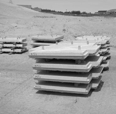
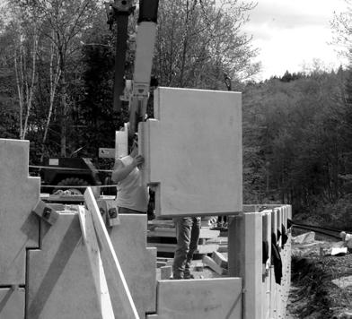
9 A. Concrete Facing Panels IV. Handling Reinforced Earth Materials Panel Delivery - Prior to the start of construction, the Contractor should establish a panel delivery schedule that will allow The Reinforced Earth Company s precaster to match their panel production and delivery to the Contractor s construction schedule. Panels are usually delivered on flatbed trailers in stacks of four or five panels high. The delivery point is made as close to the retaining walls as a truck can be driven under its own power. Panels should be free of any surface defects that may occur in transportation, unloading, or storage at the construction site, including: Chipped or broken front corners. Permanent stains on exposed face. A crack in panel s exposed face. These panels may be repaired before they are used in the structure. Any repairs to panels must be completed to the satisfaction of the Engineer. Figure 3 Never re-stack panels without dunnage. Never place panels face down directly on the ground. Never stand panels up on end. Unloading Panels - Under normal conditions, a twohour unloading period is allowed per delivery to unload panels. In this time, panels may be placed directly into the structure being constructed or temporarily stacked following either of these methods: 1. by using lifting devices to lift and handle individual panels (Figure 3) OR 2. by using nylon slings to lift and handle individual or stacks of panels (Figure 4) Care must be taken to protect facing panels from damage during handling and storage. Panels can be stored at the job site by re-stacking. Select a location with firm, level ground for both stability and to protect panels from staining. Carefully lift and place each panel face down on the nylon pads of the dunnage. Stacks should be no more than five panels high with dunnage used between each panel as illustrated in Figure 5. Figure


.")
10 Panel Storage - Panels should be securely set and blocked on firm, level ground to prevent damage and staining during storage. Figure 6A Figure 5 Note: All dunnage and pallets remain the property of The Reinforced Earth Company. They should be stacked and made available for pick-up as soon as they are no longer needed for panel storage. B. Reinforcing Strips, Fasteners, and Joint Materials Reinforcing strips - Strips may be up to 32 ft. long and are delivered to the site in bundles of 25 each. Each bundle weighs approximately 30 lbs. per linear ft. Storage in the open is acceptable but bundles should not be placed directly on the ground (Figure 6A). Figure 6B High Adherence (HA) Ladder Reinforcing Strips - alternate reinforcement type (Figure 6B)
. Fasteners - Sets of 500 bolts, washers and nuts are packed in containers, each weighing")
 are supplied in plastic bags, each containing up to 100 of the 2-in")


11 Bearing Pads - Rubber bearing pads are packed in cartons each weighing 50 to 75 lbs (Figure 7). Fasteners - Sets of 500 bolts, washers and nuts are packed in containers, each weighing 125 lbs (Figure 7A). Filter cloth - Filter cloth is supplied in 18-in. wide rolls. Foam strips (if required) are supplied in plastic bags, each containing up to 100 of the 2-in 2, 7 to 9 ft. strips. In addition to normal security, filter cloth and foam must be stored in a sheltered location, protected from the elements (Figure 8). Figure 7 Figure 8 Adhesive - Adhesive for filter cloth is supplied in appropriate containers. Adhesive tubes must be stored in a dry location and protected from the elements (Figure 9). Figure 7A Figure

12 V. Construction Procedures A. Overview The basic erection sequence for a Reinforced Earth structure can be summarized in these steps: Prepare the site including excavation and installation of drainage systems if required. Form and pour leveling pad (see Step B-3 for tolerances). Set and brace the initial course of facing panels, which consists of alternating half- and full-height panels. Use wood wedges and clamps to hold panels in position. Attach filter cloth with adhesive. Spread and compact backfill in lifts up to 1 to 2 inches above the lowest level of panel tie strips Connect reinforcing strips to panel tie strips. Spread and compact backfill in lifts to within 3 to 5 inches of the top of the half panels. Place bearing pads and set the second course of full panels Repeat cycle of backfilling and compacting in lifts, connecting strips, placing filter cloth and bearing pads and setting panels until design height is reached. As each course is completed, remove the wooden wedges from the panels in the course three levels below. Set top panels; connect strips, complete backfilling and compaction. Remove all wedges and clamps. Install concrete coping, traffic barriers, or any C.I.P. concrete as required. The following position, alignment and procedures should be reviewed prior to the start of construction. Lifting, Placing and Spacing Panels - Panels can be lifted from the horizontal, or stacked position, directly to a vertical position by attaching a lifting device to each of the two cast-in-place lifting inserts at the top edge of the panel (Figure 3). Use dunnage as blocking to prevent damage as each panel rotates from horizontal to vertical (Figure 10). Figure 10 As each panel is lowered into its place in the structure, use the ¾-in. wooden spacer to achieve approximately a ¾-in. joint (Figure 11). The finished appearance of a Reinforced Earth structure depends to a large extent on the care taken in erecting and positioning facing panels. For this reason, particular attention must be paid to the initial course of facing panels and to backfill placement. Close attention to detail and accuracy at this point will help ensure trouble free and rapid construction of the remainder of the structure. Figure
 so that the surfaces of successive panel courses are aligned.")

13 Check alignment - Visually check the alignment of each panel in relation to either the control line on the leveling pad for the initial course of panels or to the panel below in subsequent courses. Make adjustments with a crowbar on the fill sides of the panel (Figure 12) so that the surfaces of successive panel courses are aligned. Do not attempt to adjust the panel by using the crowbar on the front side this can result in unacceptable chipping or spalling. Set Batter - Panels must be given a slight batter, or tilt, toward the backfill in order to compensate for a subsequent outward movement, which occurs during backfill placement and compaction. This movement will tend to push the panel to a true vertical position. Measure batter using a 4 ft. level (Figure 14). Adjust panel base to the rear Adjust panel base to the front Figure 12 ADJUST PANEL ALIGNMENT Check horizontal level. The horizontal level of each panel should be checked and adjusted in order to assure a uniform appearance and even joints throughout the structure. Small rubber shims are provided to aid in leveling the panels. Figure 14 Set the batter by pulling back on the top of the panel from the fill side. Batter of the initial course can be set with turn buckles. To maintain the batter, drive one wooden wedge from the face of the structure into each of the short horizontal panel joints at the shoulder of the panel and/or the vertical joint and clamp the panel to the adjacent panels (Figures 16,17 and 18). Figure 13 As shown in Figure 13, use a 4 ft. level to verify that the new panel is level. Then sight back along the tops of the panels to ensure that the new panel is at the elevation of the others in its course. Correct any variations by lifting the panel slightly and inserting rubber shims in the horizontal joint at the panel base. Recheck the horizontal spacing and alignment after any such adjustment. The horizontal panel joint wooden wedges should remain in place during the erection of three subsequent courses but must be promptly removed. If wedges are left in place for more than three courses, removal will be difficult and spalling can occur. Vertical joint wooden wedges must be removed prior to placement of the next panel course. 14
14 The amount of batter varies and depends on the type and moisture content of the backfill, required compaction, type of compaction equipment, and length of the reinforcing strips. A batter of ½-in. in 4 ft. is generally used as a starting point. Coarse backfill, such as crushed stone, may require less batter, while fine backfill, such as sand, may require more. Monitor the actual movement of panels during the placement and compaction of each lift of backfill; adjust the amount of batter according to field conditions. Vertical Alignment Check - During construction, check the overall verticality of the structure using a plumb bob. This should be done on panels completely backfilled. Make any changes in batter necessary to assure that final verticality is within tolerances (see specifications), in subsequent lifts of panels. Erection Tolerances The overall vertical alignment tolerance, or plumbness, from top to bottom of the structure, shall not exceed ¾-in., per 10 ft. of height. Vertical and horizontal alignment tolerance, and plumbness, shall not exceed 3/4-in. when measured with a 10 ft. straight edge on a selected wall section. Vertical and horizontal alignment should be checked at every course throughout the erection process. The maximum allowable offset between any two panels shall not exceed one inch. Horizontal and vertical joints should be uniform in appearance. Corrective action should be taken immediately when any of the specified tolerances are exceeded. B. Foundation Preparation Step B-1: Excavation - Excavate the site to the depth and width specified on the Plans for the length of the section to be built. Remove all unsuitable material and replace it, as necessary, with compacted fill as directed by the Engineer. If required by the Specifications and as directed by the Engineer, proof-roll the foundation to a density suitable for the bearing pressure shown on the Plans. In the event of an over-excavation of the sub-grade, the Engineer must approve the gradation, placement, and compaction of replacement material. Evaluation and approval of foundation suitability is the responsibility of the Engineer. Any foundation soils found to be unsuitable shall be removed and replaced with material approved by the Engineer. The material shall then be compacted, as directed by the Engineer, to a density suitable for the bearing pressure as shown on the Plans, Specifications, and Contract Documents. Foundation evaluation and control are critical; the behavior and performance of a Reinforced Earth structure is largely dependent upon the foundation on which the reinforced volume is placed. Step B-2: Drainage System(s) - Install any drainage system(s) as required by the Plans and Specifications or as directed by the Engineer. Step B-3: Leveling Pad - An unreinforced smooth finish concrete leveling pad is formed and cast at each foundation elevation. Leveling pads have nominal dimensions of 6-in. thick by 1 ft. wide and are cast using a minimum 2,000-psi, 28-day compressive strength concrete. Leveling pads should cure for a minimum of 12 hours before the setting of panels. Leveling pads must be cast to the design elevations as shown on the Plans. The allowable elevation tolerances are ft (1/8-in) and 0.02 ft. (1/4-in.) at design elevation. An improperly placed leveling pad can result in subsequent panel misalignment and decreased wall construction productivity. If the Plans call for the structure to have a step-up in elevation, pour the higher leveling pad so that its surface is 1.23 or 2.46 ft. above those of the lower pad depending on the Plans. Leave a 1 ft. maximum gap between the higher pad and the start of the lower pad at the step-up location (Figure 15)

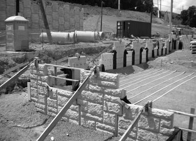
15 Bearing pads are not used under the first course of panels between the leveling pad, unless specifically shown on the Plans or separately authorized in writing by The Reinforced Earth Company. If needed, only rubber shims may be used to shim between the leveling pad and first course of panels. Permanent wood shims are not permitted at any point in the structure. Brace the initial course of panels by securing an adequate lumber brace to each full height (A or P) bottom panel and to any panel taller than 3 ft. External bracing is not required on subsequent courses. Panels must be braced as shown in Figure 18 and 19 prior to releasing the crane from the panel. Figure 15 Step C-2: Second Panel Placement - Place the second panel (2) on the leveling pad and place a ¾-in. spacer between it and panel (1) (Figure 16). These spacers should remain in place until the wall is backfilled to the height of the half size panels. Spacers must be used during panel erection. Spacers are supplied by the Contractor and may be fabricated from any available ¾-in. material. Step B-4: Wall Line - On the leveling pad establish a layout line for the face of the structure. This may be different than the wall s LOL given in the contract documents. C. Erecting the Initial Panel Course Step C-1: Panel Placement - Panel layout usually begins at the lowest leveling pad or a fixed point such as a corner or existing structure (Figure 16). Place the first B n (half) panel (1) on the leveling pad. Check the horizontal level and shim as needed. Align the face of the panel along the layout line; and using bracing in addition to wooden wedges at the base of the panel, set the batter for the panel. Throughout construction it is of utmost importance that the panel type and number of tie strips of each panel match the requirements as shown on the approved Plans. Figure 16 Step C-3: Setting Panel Batter - Set the panel s batter as before. Wooden wedges are used temporarily at the panel shoulders to set batter in the panels. These wedges must be removed once the wall is three panels high. Clamp the panel to panel (1) as shown in Figure 17. Tighten clamps sufficiently to hold the panel in position without movement. Brace the initial course of panels by securely attaching an adequate lumber brace to a bracing clamp attached to the top of each full panel and to any panel in excess of 3 ft. in height (Figures 18 and 19). Bracing is not required on subsequent courses 16


16 2 X 4 Lumber 2 X 4 Lumber (minimum) Stake or Pin BRACED INITIAL COURSE OF PANELS Figure 17 Figure 19 Step C-4: Place a third panel (3), aligning the panel with the control line and use a ¾-in.spacer to ensure spacing. Check the horizontal level of the panel and shim as necessary. Set the panel s batter. Step C-5: Continue setting the panels in this manner and site back along the tops of the full height panels to assure that each new panel is at the elevation of the others in that course (Figure 13). After ten panels have been set, recheck the wall s alignment by sighting along the wall face. Adjust panels if needed to obtain a true line. D. Joint Materials Step D-1: Joint materials are installed from the backfill side of the structure only. Filter cloth prevents the loss of fine backfill particles while allowing the structure to be free draining. Bearing pads prevent concrete-toconcrete contact between facing elements vertically. Filter Cloth is affixed to the backfill side of both the vertical and the horizontal panel joints (Figure 20) using several dabs of a contact adhesive. Figure 18 Bracing must remain in place until the braced panel has all the reinforcing strips attached and the backfill has been placed and compacted up to the top of the braced panel. The adhesive provides a temporary attachment for the filter cloth and should be used sparingly. It is not recommended that the filter cloth be glued solid to the back of the panel. Filter cloth is not generally required at the base of the wall where the panel rests on the leveling pad. Bearing pads are placed in grooves on top of each panel. Thickness and/or quantity at various levels within the structure may differ and must be in strict accordance with the Plans
.")

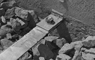
17 Bearing pads are designed to compress during the construction process. The initial joint created by the bearing pads may decrease in size when the wall is completely constructed. Bearing pad horizontal-joint material Step E-1: Place and compact initial lifts of Select Granular Backfill up to bottom row of panel tie strips (Figure 21). Note that the uniform loose thickness placement of each lift of backfill material must not exceed 1 ft. The level of the compacted backfill should be 2+ inches above the tie strips as shown in Figure 22. In order to avoid pushing the braced panels out of alignment, initial lifts of backfill are neither placed nor compacted against the back of the panels Only after the first layer of reinforcing strips has been connected to the panel tie strips as detailed in Section E and a lift of backfill placed and compacted over the strips can backfill then be placed and compacted against the back of the panels illustrated in Figure 23. Compact each backfill lift using a large smooth-drum vibratory roller except within a 3 ft. zone directly behind the panels where a small hand-operated vibratory compactor must be used to avoid undue panel movement. Figure 20 After compaction has taken place, check wall alignment visually and with a level adjust panels as necessary. E. Backfilling The constructability and performance of a Reinforced Earth structure directly relates to the quality of the Select Granular Backfill and to the manner in which it is installed. Prior to placing the Select Granular Backfill, the Contractor shall certify to the Engineer that the material conforms to the requirements stated in the Plans, Specifications, and Contract Documents for Reinforced Earth structures. Figure Select Granular Backfill material to be used in the reinforced volume must be tested and shown to strictly conform to the Specifications. Material, which does not conform, cannot be used as Select Granular Backfill. Bolt connection Reinforcing Strip Place backfill to level as shown 2 + BACKFILL SLOPE AT CONNECTION Figure

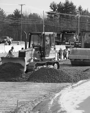
18 3-4 At a minimum, Select Granular Backfill material must be compacted to 95% of maximum density, per AASHTO T-99, methods C or D (with oversize correction as outlined in Note 7). Figure 23 The gradation of the Select Granular Backfill should be tested periodically during construction to assure compliance with the Specifications. This gradation testing should be performed for every 2,000 cubic yards of material placed and/or whenever the appearance or behavior of the material noticeably changes. Immediate gradation and moisture testing is required if either excessive panel movement or backfill pumping occurs during construction. Step E-2: Compaction - Large smooth-drum vibratory rollers are used to accomplish mass compaction of Select Granular Backfill materials, except for fine uniform sands. Sheep foot Rollers are never to be used for compaction of Select Granular Backfill. Fine uniform sands, which contain more than 60 percent passing a No. 40 sieve used for Select Granular Backfill, must be compacted using a smooth-drum static roller. Vibratory compaction equipment should not be used to compact fine uniform sands. If 30% of the Select granular Backfill material is greater than 3/4-in. in size, AASHTO T-99 is not applicable. For such material, the acceptance criterion for compacting is either a minimum of 70% of the Relative Density of the material as determined by ASTM D-4253 and D-4254, or a Method Specification based on a test compaction section which defines the type of equipment, lift thickness, number of passes of the specified equipment and placement moisture content. Moisture content of Select Granular Backfill material during placement should be approximately 1% to 2% less than its optimum moisture content. The minimum frequency of compaction testing shall be one test per lift of Select Granular Backfill material placed. Test locations are determined by the Engineer. Step E-3: Grading - At the end of each day s work, backfill must be graded to slope away from the back of the panels in order to divert water runoff from the structure area. Failure to properly grade the backfill can result in excessive water in the Select Granular Backfill and cause subsequent movement of the panels beyond alignment tolerances. Compaction within 3 feet of the back face of the panels shall be achieved by at least three passes using a lightweight mechanical tamper, roller or vibratory compactor. Compaction testing should not be performed in this 3 foot zone

, and tightening.")
19 F. Reinforcing Strips Step F-1: Place reinforcing strips on the compacted backfill. Position strips perpendicular to the facing panels, unless otherwise shown on the Plans. Reinforcing strips are supplied in lengths as shown on plans, with a tolerance in length from 0-in. to + 8-in. Connect each reinforcing strip to the embedded panel tie strip by inserting the end of the reinforcing strip into the gap between the two exposed ends of the tie strip. Match the three holes and push a bolt through the holes from below, placing a washer on top, threading on a nut (Figure 24), and tightening. Bolts must fit up through both tie strip flanges, perpendicular to the steel surfaces, and have full bearing of the bolt head and washer/nut against the tie strip flanges. Use a crescent or socket-head ratchet to securely hand tighten the nut. The placement of any reinforcing strip in a skewed manner, unless shown on the Plans, Specifications, and Contract Documents, must be authorized in writing by The Reinforced Earth Company prior to placement in the field. Step F-2: Dump backfill onto the reinforcing strips so that the toe of the backfill pile is 3-4 ft. from the panels. Spread the backfill by pushing the pile parallel to the panels and wind rowing it toward the panels and toward the free end strips. If strips are long, a second load may be required to backfill to the ends of the strips. If so, dump and spread this load only after spreading the first. Continue to backfill to the full height of the half panels (Figure 23). Metal tracks of earthmoving equipment must never come in contact with the reinforcing strips. Rubber-tired vehicles, however, can operate directly on the exposed strips if backfill conditions permit and care is exercised. Step F-3: Step-up: If required to make a step-up in elevation of the wall, use the following procedure. Figure 24 Reinforcing strips should be placed perpendicular to the back of facing panels. However, in specific, limited situations, it may be necessary to skew a reinforcing strip from its design location (perpendicular to the facing panel) in either the horizontal or vertical plane. Mark a wall layout line on the upper level pad to establish a wall-face control line. Place the next required panel along the control line, space ¾-in. set its batter and brace if necessary. Then continue construction of the upper course using the procedure used on the lower level. Design of the Reinforced Earth structure is based on the perpendicular placement and connection of reinforcing strips, unless otherwise detailed on the Plans, and on installation of the correct density and length of strips to each panel. Figure


20 G. Constructing Second and Subsequent Courses Step G-1: Only after backfill has reached the top of the B (half) panels can construction of the second course begin. Throughout construction, panels should only be set after backfilling and compaction to grade has been completed. Placing any panel atop a panel, which has not been completely backfilled can create an unstable situation, and lead to misalignment of panels, and is strictly prohibited. Continue to set A panels in the same sequence. As the work proceeds, check the wall s alignment frequently. Install joint materials as in step D-1. Step G-5: When the course of panels is complete and after vertical and horizontal filter cloth has been installed, place backfill in lifts according to the Plans, Specification, and Contract Documents up to 2-in. above the tie strip level. Figure 27 illustrates the sequence for backfilling the second and subsequent courses. Step G-6: After backfilling, recheck the batter and alignment of the wall, then place and connect the next layer of reinforcing strips as in step F-1. Begin the second and subsequent courses of panels at the end of the wall where construction began (Figure 26). Step G-2: Remove the two shoulder clamps holding A panels (2) and (4) to B panel (3). (As each course proceeds, remove only two clamps at a time to allow for setting of each new panel.)(figure 26) To prevent concrete-to-concrete contact at horizontal joints, set two bearing pads onto the top edge of panel (3). Figure 26 Step G-3: Set A panel (101) onto B panel (3) (Figure 26), centering the panel to ensure equal vertical joints and matching the panels front face to that of panel (3). Set the batter of the panel the same as the first course using wedges at the ear. Clamp the new A panel (101) to the initial course panels (2) and (4). Don t over tighten the clamps as they may remove the batter set in the panel (101). Step G-4: Remove the next pair of clamps; place bearing pads onto the half panel (5); and set A panel (102) onto it. Match the face of the panel just placed to that of the panel below, and set its batter. Clamp the panel (102) to adjacent panels (4) and (6). Figure

21 Step G-7: Backfill up to the top of the A (full) panels of the initial course and the bracing can now be removed. If after backfilling to the top of the A panels, panels of the initial course did not become almost vertical, or if panels have gone beyond the vertical, adjust the amount of batter in the second course so that the third row will become vertical after backfilling. Placement and compaction of part or all of a berm or an embedment at the lower front surface of the structure can begin (Figure 28). Removal of the spacers at the base of the wall must be complete prior to placing this material. Reinforced Earth structures with a leveling pad at or above existing grade requires placement of an earth berm as toe protection along the face. Structures with a leveling pad below existing grade require the placement of an embedment in front of the wall. The height of the berm or the depth of the embedment is shown on the Plans. The berm or embedment must be placed immediately to prevent erosion before the wall reaches 50% of its height or 20 ft., whichever is less. Step G-8: When backfill reaches the top of the initial course of full panels (which is halfway up the second course), begin placing the next course of panels. Repeat steps G-1 through G-5 for panel installation, backfill placement and compaction, reinforcing strip installation, and placement of horizontal/vertical joint materials. Follow these same procedures for the second and subsequent panel courses until the structure is ready to be topped off. No external panel bracing is required for second or subsequent courses. After the erection of each course of panels, the wooden wedges of that course and the two courses below it should be checked to ensure that they are securely seated. At least two, but no more than three rows of panel wedges should remain in place at all times during erection. When construction is complete, all wedges must be removed. Panel batter should be checked after backfilling each course with necessary adjustments made in subsequent courses to ensure plumbness. Quality control requirements for Select Granular Backfilling, including density and placement moisture, are the same for the second and subsequent courses as for the first course, unless otherwise indicated in the Plans or Specifications. H. Completion of the Wall Figure 28 Step H-1: In placing top course panels, the construction sequence continues as previously outlined. However, top course panels have either a flat or a sloping edge and may be supplied in varying heights to meet finished-elevation requirements. Refer to the Plans for the location of specific top panels. Step H-2: After backfilling is complete, remove all clamps and wooden wedges from the structure. Step H-3: Install top wall treatment. If required. Several types are commonly used: Cast-in-Place - If required, rebar for connection will protrude from top panels. All necessary attachment details for a barrier, coping, parapet, or paved ditch will be shown in the plans. Precast Coping - If approved, precast coping will be supplied. Attachment details will be shown in the Plans. Plain - The top of panels will remain exposed with no further treatment necessary. Sometimes called stepped top. 22
22 VI. Condition-Cause Relationships Reinforced Earth structures are to be erected in strict compliance with the structural and aesthetic requirements of the Plans, Specifications, and Contract Documents. The desired results can be achieved through the use of quality materials, correct construction procedures, and proper inspection. However, considering the nature of construction work, there may be occasions when dimensional tolerances and/or aesthetic limits are exceeded. Corrective measures must be taken immediately to return the structure to acceptable tolerances. CONDITION 1. Distortion in Wall (a) Differential settlement or low spot in wall (b) Overall wall leaning (c) Panel contact, resulting in spalling/chipping 2. (a) First course difficult to set and/or maintain level. (b) Panel-to panel contact resulting in spalling and/or chipping. 3. Wall Leaning Out 4. Wall Leaning In 5. Wall Out of Horizontal Alignment Tolerance, or Bulging 6. Panels Do Not Fit Properly in Intended Locations Resulting In Subsequent Panels Spalling or Chipping CAUSE Foundation (subgrade) material too weak or wet for proper bearing. If fill material, poor quality or improper compaction. Leveling pad not within tolerance. a) Panels not battered sufficiently. b) Large backfill placing and/or compaction equipment working within 3-ft. zone of back of wall. c) Backfill material placed wet of optimum moisture content. d) Backfill contains excessive fine materials (beyond the Specifications for percent of materials passing a No.200 sieve). e) Backfill material pushed against back of wall before being compacted on strips. f) Excessive or vibratory compaction on uniform fine sand (more than 60 percent passing a No.40 sieve). g) Backfill material dumped close to free end of reinforcing strips, then spread towards back of wall, causing bulge in strips and pushing panel out. h) Wedges not seated securely. i) Clamps not tight. j) Excessive compactive effort. k) Excessive lift thickness. l) Plasticity index of backfill material in excess of specification limits. a) Excessive batter set in panels for Select Granular Backfill material being used. b) Inadequate compaction of backfill. (a) See causes 3C-G, and 3I. (b) Backfill saturated (heavy rain or improper grading of backfill after each day s operation). (a) Panels are not level. (b) Differential settlement (see Condition 1). (c) Failure to use spacers between panels. (d) Leveling pad incorrect
 Where (X) can be a letter or digit B.")
23 VII. Appendix A. Facing Panel Types and Nomenclature A. Panel Designations: All design and/or shop drawings, and precast panels, are designed as follows: Key to Panel Designation: XX X RX X.XX Basic Panel Type Panel Modification Number of Tie Strips Panel Reinforcement Panel Width Or Deflection Angle (for bent panels) Where (X) can be a letter or digit B. Standard and Top Panels: The following table to the right lists the designations of standard and top-course panel types and their surface areas. The standard panel width is 4.92 ft., measured between panel alignment locations at the center of the panel ear(s). SURFACE AREA SURFACE AREA A 24.2 sq. ft 2.25m 2 G 22.9 sq. ft 1.94m 2 B 12.1 sq.ft 1.12m 2 H 24.2 sq. ft 2.22m 2 C 8.8 sq ft 0.82m 2 K 27.0 sq. ft 2.50m 2 D 12.1 sq.ft 1.09m 2 L 30.0 sq. ft 2.78m 2 E 14.9 sq. ft 1.38m 2 P 30.0 sq. ft 2.81m 2 F 17.9 sq. ft 1.66m 2 Q 17.9 sq. ft 1.68m 2 A B P Q 24
 or R (right) after the panel designation (e.g., AL, AR).")

 D.")
24 C. Cut Panels: Any standard panel may be cut vertically to fit specific field or design conditions. Cut panels are indicated by the letter L (left) or R (right) after the panel designation (e.g., AL, AR). Widths of cut panels are indicated on the construction drawings E. Blocked-out Panels/Specials: Any standard panel may require special modification in order to meet job specific requirements. Designation contains letter of standard panel type with an additional letter plus number suffix, as required to name panel. AR X=WIDTH SHOWN ON REINFORCED EARTH CONSTRUCTION DRAWINGS AL A1Q AX (front views) D. Sloping Top Panels: Panel tops which slope downward at a 2:1 slope are indicated by the letter M or N after the panel designation. Panel tops which slope downwards at an 8:1 or 4:1 slope are indicated by the designation I, J, or II, JJ respectively after panel designation. HN HM HI HJ HII HJJ
25 F. Corner Elements: Corner elements are designed to accept vertical cut panels and cover a range of bends. The corner element designations are CE1A, CE2A, CE3A, and CE4A. The letter following indicates corner element height. Corner element details and shape may vary. Refer to the Plans and Specifications. G. Slip Joint Cover: Slip joints are designed to accept vertical cut panels and provide system flexibility and rapid changes in elevation. The cover designation is the letter J. The following letter indicates the joint height. CE2A CE4A JA (Top views) (Note): Joint covers are all plain (no liner) finish CE3A CE1A 3/4 (typ) H. Blind Slip Joint: Again, the slip joint is designed to accept vertical cut panels and provide system flexibility for varying foundation conditions. The cut panels are assembled with a ¾-in. butt joint. The letter Y designates the back-up panel and the following letter indicates the panel height (top view) Note: Corners are all plain (no liner finish) YA 3/4 (Top views) 26
26 B. Glossary of Terms Agency Contract Documents Contractor Engineer Inspector Owner Plans Specifications Technical Advisor Work The person(s), firm, or corporation acting as Agent for the Owner. The Owner-Contract agreement, including the conditions of the Contract (general, supplementary, and other conditions), the drawings, Specifications and the provisions of the agreement between the Contractor and The Reinforced Earth Company; and also including all addenda issued prior to execution of the Contract, all modifications thereto and any other items specifically stipulated as being included in the Contract Documents. The individual, firm or corporation undertaking the execution of the Work under the terms of the Contract, and acting directly through its Agents or employees. The person(s) designated by the Owner, as having authoritative charge over certain specific engineering operations and duties. The authorized representative assigned to make a detailed inspection of any or all portions of the Work or materials thereof in the Owner s behalf. The Owner of a project. The agency, person, firm or corporation with which a Contract has been made for the payment of the Work performed under the Contract. The official approved plans, profiles, typical cross sections, working drawings and supplemental drawings, or exact reproductions thereof, which show the locations, character, dimensions and details of the Work to be performed. A description, for contract purposes, of the materials and workmanship required in a structure(s), as also shown on the related working drawings. The written material containing the standard provisions and special provisions, as may be necessary, pertaining to the quantities and qualities of materials to be furnished under the Contract. Representative of The Reinforced Earth Company who may be available to assist the Contractor with material scheduling and coordination, and give advice on the recommended construction procedures applicable to Reinforced Earth structures as set out in this manual. The entire scope of the Work to be performed at the site of the construction project including labor, materials, equipment, transportation and such other facilities as are necessary to fulfill all obligations under the Contract
27 C. Safety Tips for Unloading Reinforced Earth Products 1. Upon arrival of truck, examine the load for any shifting or unstable conditions prior to removing tie downs. 2. The truck should be on level ground when unloading. Unloading on unlevel ground could result in shifting of panels or possibly panels falling from trailer. 3. Lifting equipment (straps, cables, ring clutches, etc.) should be checked for excessive wear or cracking prior to unloading truck. 4. Do not move the tractor while product is not tied down. 5. If drivers are required to remove chains or binders next to lane of moving traffic, cones and flagman should be used to direct traffic away from the trailer and driver. 6. Drivers are not trained as riggers or swampers and should stay in cab or clear away from unloading operations. The drivers are acting in a delivery capacity only. 7. Personal protective equipment required by the general contractor on site should also be required of delivery drivers. 8. Personnel should not be allowed under a suspended load. 9. Once removed from the trailer, panels not placed directly in the wall should be stacked or secured on flat ground to prevent tipping or falling. 10. Areas between the truck and crane should be restricted to personnel required to unload trailer. 11. If any unsafe situations exist while loading or unloading RECo products, contact The Reinforced Earth Company immediately to eliminate any hazards or exposure to illness or injury. 28
28 D. The Reinforced Earth Company Offices The Reinforced Earth Company maintains full-service offices throughout the United States. Contact the office serving your area for technical service: Southeast Region Atlanta, GA (770) Northeast Region Boston, MA (978) Central Region Dallas, TX (817) Midwest Region Chicago, IL (630) Southwest Region San Diego, CA (858) Western Region Denver, CO (303) Central-Northeast & Mid-Atlantic Region Reston, VA (703) Florida Region Orlando, FL (407) Corporate Headquarters The Reinforced Earth Company Sunrise Valley Drive, Ste 400 Reston, VA Telephone: (703) or (800)

29 SAFETY BULLETIN February 25, 2014 Re: Safety Reminder for Reinforced Earth Panel Installation Please review the Reinforced Earth Construction Manual carefully and practice safety in all aspects of handling and installing Reinforced Earth wall materials. The following provides important safety reminders when handling and installing wall panels: 1. Panels at the levelling pad course should be externally braced as shown in the construction manual upon installation and before additional panels are installed. 2. Panels must remain attached to lifting equipment until such time as external bracing, wedges and shoulder clamps are in place and secured. 3. All subsequent panels must remain attached to the lifting equipment until alignment adjustments have been made and wedges and clamps have been installed and secured. 4. Cut panels adjacent to a cast-in-place structure require special attention. Bracing, wedging and clamping is required before releasing the panel from the lifting equipment. Timber or steel angle can be anchored to the vertical surface of the adjacent cast-in-place structure and then the cut panel can be wedged and clamped to the secured timber or angle. 5. The last panel at the free end of wall should be externally braced on the free end as well as secured with wedges and a clamp to the adjacent panel. Please ensure your crew is aware of the above safety reminders.
REINFORCED EARTH. Construction and Quality Control Procedures Manual. Construction Manual: Rectangular Panels. Rectangular Panels
 REINFORCED EARTH Construction Manual: Rectangular Panels Construction and Quality Control Procedures Manual Rectangular Panels CONSTRUCTION AND QUALITY CONTROL PROCEDURES MANUAL CONTENTS I. Preface...4
SPECIFICATION FOR REINFORCED SOIL WALL
 SPECIFICATION FOR REINFORCED SOIL WALL 1.0 EXTENT OF WORK The work shall consist of Reinforced Soil walls built in accordance with this specification and in conformity with the lines, levels and details
ARES RETAINING WALL SYSTEMS. installation guide and construction manual
 ARES RETAINING WALL SYSTEMS installation guide and construction manual When long-term performance and speed of construction are important, ARES Retaining Wall Systems offer unmatched advantages. Tensar
SECTION SPECIFICATION FOR STONEBRIDGE RETAINING WALL SYSTEM
 SECTION 32 32 23 SPECIFICATION FOR STONEBRIDGE RETAINING WALL SYSTEM PART 1: GENERAL 1.01 Scope Work includes furnishing all materials, labor, equipment, and supervision to install a Stonebridge segmental
LANDSCAPE RETAINING WALLS
 SUDAS Standard Specifications Division 9 - Site Work and Landscaping Section 9070 - Landscape Retaining Walls LANDSCAPE RETAINING WALLS PART - GENERAL.0 SECTION INCLUDES A. Modular Block Retaining Walls
SPECIFICATIONS FOR PRECAST MODULAR BLOCK RETAINING WALL SYSTEM (revised 5/8/7)
") Page 1 of 7 STONE STRONG SYSTEMS SPECIFICATIONS FOR PRECAST MODULAR BLOCK RETAINING WALL SYSTEM (revised 5/8/7) PART 1: GENERAL 1.01 Description A. Work includes furnishing and installing precast modular
Page 1 of 7 STONE STRONG SYSTEMS SPECIFICATIONS FOR PRECAST MODULAR BLOCK RETAINING WALL SYSTEM (revised 5/8/7) PART 1: GENERAL 1.01 Description A. Work includes furnishing and installing precast modular
Uwall UNIVERSAL CONSTRUCTION MANUAL
 Uwall UNIVERSAL Retaining Wall System CONSTRUCTION MANUAL TM President s Letter CSI is a leader in its industry supplying precast infrastructure products throughout New England and beyond since 1972, developing
SECTION PERMEABLE INTERLOCKING CONCRETE UNIT PAVEMENT
 SECTION 32 14 13 19 PERMEABLE INTERLOCKING CONCRETE UNIT PAVEMENT SECTION 32 14 13 19 PERMEABLE INTERLOCKING CONCRETE UNIT PAVEMENT PART 1 - GENERAL 1.1 SUMMARY A. Section Includes: 1. Permeable Articulating
BIO-AQUIFER STORM SYSTEM
 BIO-AQUIFER STORM SYSTEM Specifications for Construction PART 1 GENERAL 1.01 SECTION INCLUDES A. Providing labor, materials, tools and equipment to furnish and install a permeable concrete paving stone
STANDARD SPECIFICATION FOR CRIBLOCK CONCRETE CRIBWALL
 STANDARD SPECIFICATION FOR CRIBLOCK CONCRETE CRIBWALL 1. SCOPE 2. DESIGN 3. MATERIALS 4. CONSTRUCTION 5. METHOD OF MEASUREMENT AND PAYMENT SCOPE This Specification sets out requirements for the design,
SECTION RIPRAP, BOULDERS, AND BEDDING
 SECTION 31 37 00 RIPRAP, BOULDERS, AND BEDDING PART 1 GENERAL 1.01 SECTION INCLUDES A. The WORK includes excavation, grading, and installation of riprap, boulders, soil riprap, void-filled riprap, and
Construction Procedures
 Construction Procedures 2014 Rev. 1.6 1 Introduction This manual presents the methods and procedures necessary for the proper erection of a LOCK+LOAD retaining wall. problems later during the service life
Redi Rock Specification and Installation Manual
 Redi Rock Specification and Installation Manual 1.0 General Scope This Specification covers the Design, Materials and Installation of Redi Rock modular block Retaining and Freestanding Wall systems as
DESIGNING AND CONSTRUCTION OF T-WALL RETAINING WALL SYSTEM
 Istanbul Bridge Conference August 11-13, 2014 Istanbul, Turkey DESIGNING AND CONSTRUCTION OF T-WALL RETAINING WALL SYSTEM T. C. NEEL and K.BOZKURT ABSTRACT This work shall consist of the design, manufacture
SECTION UNCLASSIFIED EXCAVATION AND GRADING
 SECTION 02210 UNCLASSIFIED EXCAVATION AND GRADING PART 1 GENERAL 1.1 DESCRIPTION Work in this section includes the excavation, undercut excavating, grading, earthwork and compaction required as shown on
DIVISION 03 CONCRETE SPECIFICATION : FORMS AND FORMWORK
 DIVISION 03 CONCRETE SPECIFICATION 031000: FORMS AND FORMWORK PART 1.0 GENERAL 1.1 DESCRIPTION The work of this specification includes furnishing of all labor, materials, equipment and incidentals to install,
TRICON TM RETAINED SOIL WALL SYSTEM
 T R I C O N P R E C A S T L T D. TRICON TM RETAINED SOIL WALL SYSTEM CONSTRUCTION MANUAL TRICON TM RETAINED SOIL WALL SYSTEM The Tricon TM Retained Soil Wall System is a mechanically stabilized earth retaining
INDEX FOR SPECIFICATIONS FOR REMOVING CULVERTS AND PLACING CULVERTS SCOPE... 1
 March 2002 No. 400 INDEX FOR SPECIFICATIONS FOR REMOVING CULVERTS AND PLACING CULVERTS 400. 1 SCOPE... 1 400. 2 REMOVING CULVERTS AND TIMBER STRUCTURES 2.1 Concrete and Metal Pipe Culverts... 1 2.2 Structural
Wall Modular Block Mechanically Stabilized Earth, Item S.
 Wall Modular Block Mechanically Stabilized Earth, Item 532.0300.S. A Description (1) This special provision describes designing, furnishing materials and erecting a permanent earth retention system in
CONCRETE SEGMENTAL RETAINING WALL SYSTEM
 CONCRETE SEGMENTAL RETAINING WALL SYSTEM PART 1: GENERAL SPECIFICATIONS 1.01 Work Included A. Work shall consist of furnishing and constructing a Rockwood Classic 8, Classic 6 and Legend unit segmental
Design Manual: Gravity Wall. Section 1
 Design Manual: Gravity Wall Section 1 A Design Manual: Gravity Wall General Information Company Information Verti-Block is the latest innovative forming system from Verti-Crete, LLC. Recognized worldwide
SECTION CAST-IN-PLACE CONCRETE
 SECTION 03300 CAST-IN-PLACE CONCRETE PART 1 GENERAL 1.01 SECTION INCLUDES A. The Contractor shall furnish all work and materials, including cement, sand and coarse aggregate, water, admixtures, curing
SANDERS PRE-CAST CONCRETE SYSTEMS, INC. MSE WALL SYSTEM SUBMITTAL
 SANDERS PRE-CAST CONCRETE SYSTEMS, INC. MSE WALL SYSTEM SUBMITTAL FLORIDA DEPARTMENT OF TRANSPORTATION THE SANDERS COMPANIES 605 SOUTH INDIANAPOLIS ROAD WHITESTOWN, IN 46075 09-8-5 ISSUED FOR REVIEW REVISIONS/ISSUE
ENGINEERED SOLUTIONS SAFETY INSTRUCTIONS FOR STRUCTURAL PLATE PRODUCTS
 ENGINEERED SOLUTIONS SAFETY INSTRUCTIONS FOR STRUCTURAL PLATE PRODUCTS UNLOADING HANDLING ASSEMBLING Preface This instruction book is for your crews. Distribute it to help them safely unload and handle
ITEM 6 CONCRETE CURBS, GUTTERS, AND SIDEWALKS
 ITEM 6 CONCRETE CURBS, GUTTERS, AND SIDEWALKS 6.1 DESCRIPTION This work shall consist of constructing curbs, gutters, sidewalks, ramps, local depressions and driveways of the form and dimensions shown
StormTech Construction Guide
 A division of StormTech solid end caps and pre-cored end caps StormTech chambers StormTech manifolds and fittings Acceptable fill materials per Table 1 Woven and non-woven geotextiles 80-7 DC REQUIRED
SECTION A1 EXCAVATION AND BACKFILL GENERAL
 SECTION A1 EXCAVATION AND BACKFILL GENERAL The work under this section shall include all excavation to such width and depth as shown on the drawings, specified herein, or ordered by the Engineer. Such
Section 25 Aggregate Subbase
 Black text from standard FAA spec Strikeout text deletions from FAA standard spec Blue text additions to FAA standard spec Red text notes to the Engineer/won t appear in spec I. DESCRIPTION A. GRANULAR
SECTION STRUCTURAL PRECAST HOLLOW CORE SLABS
 PART 1 GENERAL 1.01 SCOPE OF WORK A. The Contractor shall furnish all labor, materials, equipment and incidentals to provide a complete structural precast hollow core slab system as shown on the Contract
Open-Web Truss Long Span Installation Guidelines
 TECHNICAL BULLETIN #301 Open-Web Truss Long Span Installation Guidelines RedBuilt has maintained a policy of manufacturing and marketing products of the highest quality to our customers. We guarantee the
VERTI-BLOCK - DESIGN MANUAL
 Company Information General Information Verti-Block is the latest innovative forming system from Verti-Crete, LLC. Recognized worldwide for outstanding aesthetics and performance, Verti-Crete s proprietary
T R I C O N P R E C A S T L T D. TRICON RETAINED SOIL WALL SYSTEM CrimpLock Connection System CONSTRUCTION MANUAL
 T R I C O N P R E C A S T L T D. TRICON RETAINED SOIL WALL SYSTEM CrimpLock Connection System CONSTRUCTION MANUAL TRICON TM RETAINED SOIL WALL SYSTEM The Tricon TM Retained Soil Wall System is a mechanically
SECTION LAGUNA SERIES TOP HUNG SLIDING DOOR SYSTEM
 Page 1 of 6 SECTION 08 32 20 LAGUNA SERIES TOP HUNG SLIDING DOOR SYSTEM USE THIS SECTION WHEN SPECIFYING OVERHEAD SUPPORTED GLASS SLIDING DOORS. SECTION INCLUDES OVERHEAD SLIDING TUBE ASSEMBLY, MOUNTING
PERMEABLE INTERLOCKING PAVERS
 PERMEABLE INTERLOCKING PAVERS PART 1 - GENERAL 1.01 SECTION INCLUDES A. Subgrade Preparation B. Placement of Storage Aggregate C. Placement of Filter Aggregate D. Placement of Bedding Course E. Placement
Anchor bolts ASTM F1554, Gr. 36 Wide flange beams ASTM A992, Fy = 50 ksi Misc. structural steel ASTM A36, Fy = 36 ksi
 STRUCTURAL NOTES MATERIAL STRENGTHS Structural Steel Reinforcing Steel Concrete Masonry Structural Lumber Anchor bolts ASTM F1554, Gr. 36 Wide flange beams ASTM A992, Fy = 50 ksi Misc. structural steel
SEGMENTAL BLOCK RETAINING WALLS. Comply with Division 1 - General Provisions and Covenants, as well as the following:
 SEGMENTAL BLOCK RETAINING WALLS PART 1 - GENERAL 1.01 SECTION INCLUDES Segmental Block Retaining Walls 1.02 DESCRIPTION OF WORK Constructing segmental block retaining walls. 1.03 SUBMITTALS Comply with
NPCA Precast Learning Lab. Dunnage, Loading & Shipping. Precast Show 2017 NPCA 1
 NPCA Precast Learning Lab What is it? A new library of short, educational videos What can I learn? Topics cover production best practices and sales and marketing How many videos are available? Four videos
ITEM D-701 PIPE FOR STORM DRAINS AND CULVERTS
 ITEM D-701 PIPE FOR STORM DRAINS AND CULVERTS 701-1 DESCRIPTION 701-1.1 This item shall consist of the construction of pipe culverts, and storm drains, removal of existing storm pipes, connections to existing
PAVING SLABS ON A CONCRETE BASE
 SECTION 32 14 13.16 PAVING SLABS ON A CONCRETE BASE (1995 MasterFormat Section 02784) Note: This guide specification for the U.S. is for paving slabs on a sand bed over concrete for pedestrian applications.
C. Foundation stabilization for pipe and utility structures.
 PART 1 - GENERAL 1.1 SECTION INCLUDES A. Excavating, backfilling, and compacting for utilities, including pipe, structures, and appurtenances. B. Control of water in trenches. C. Foundation stabilization
SECTION 19 - TRENCH EXCAVATION, BEDDING AND BACKFILL TABLE OF CONTENTS
 SECTION 19 - TRENCH EXCAVATION, BEDDING AND BACKFILL TABLE OF CONTENTS Section Page 19-1 TRENCH EXCAVATION...19.1 19-1.01 Exploratory Excavation...19.1 19-1.02 Trench Width...19.1 19-1.02.A Storm Drain
SECTION REINFORCING STEEL
 SECTION REINFORCING STEEL 1. DESCRIPTION This specification shall govern the furnishing and placing of reinforcing steel, deformed and smooth, of the size and quantity designated on the plans and in accordance
FIVE STAR PRODUCTS, INC. (800)
") FIVE STAR PRODUCTS, INC. www.fivestarproducts.com (800) 243-2206 Page 1 of 11 DESIGN-A-SPEC GUIDELINES FIVE STAR RS ANCHOR GEL CONTENTS PART A - GENERAL CONDITIONS PART B - MATERIAL SPECIFICATIONS PART
FIVE STAR PRODUCTS, INC. www.fivestarproducts.com (800) 243-2206 Page 1 of 11 DESIGN-A-SPEC GUIDELINES FIVE STAR RS ANCHOR GEL CONTENTS PART A - GENERAL CONDITIONS PART B - MATERIAL SPECIFICATIONS PART
SECTION PLATE CONNECTED WOOD TRUSSES
 SECTION 06173 PLATE CONNECTED WOOD TRUSSES PART 1 GENERAL 1.01 SUMMARY A. Section Includes: 1. Shop fabricated wood trusses for roof and floor framing. 2. Bridging, bracing, and anchorage. B. Related Sections:
ROOF PAVER SYSTEM National Distribution SPEC - SECTION 07760
 PART 1 - GENERAL 1.1 RELATED DOCUMENTS A. Drawings and general provisions of the Contract, including General and Supplementary Conditions and Division 01 Specification Sections, apply to this Section.
IPE WOOD DECK TILES National Distribution SPEC - SECTION 07760
 PART 1 - GENERAL 1.1 RELATED DOCUMENTS A. Drawings and general provisions of the Contract, including General and Supplementary Conditions and Division 01 Specification Sections, apply to this Section.
R-TANK SPECIFICATIONS
 TECHNICAL STORMWATER MANAGEMENT R-TANK SPECIFICATIONS PART 1 GENERAL 1.01 Related Documents A. Drawings, technical specification and general provisions of the Contract as modified herein apply to this
SECTION TRENCHING & BACKFILLING
 SECTION 02225 - TRENCHING & BACKFILLING 1.0 GENERAL 1.1 Work included in this Section includes trenching and backfilling for underground pipelines and related structures only. 1.2 Reference Specifications
1. Cast-in-place concrete is specified in Section
 SECTION 03 38 00 PART 1 - GENERAL 1.01 DESCRIPTION A. This Section describes the requirements for furnishing and installing post-tensioned slabs, jacks, jacking and anchors at Parking Structure, and record
SPECIAL CONDITIONS FOR PIPE JACKING (PJ) October, 2006
 October, 2006") Michigan Department Of Transportation 3703C (11/06) 1 Materials 1.1 Pipe SPECIAL CONDITIONS FOR PIPE JACKING (PJ) October, 2006 Page 1 of 5 The type of pipe used for the pipe jacking method shall be capable
Michigan Department Of Transportation 3703C (11/06) 1 Materials 1.1 Pipe SPECIAL CONDITIONS FOR PIPE JACKING (PJ) October, 2006 Page 1 of 5 The type of pipe used for the pipe jacking method shall be capable
ODOT Design & Construction Requirements for MSE Walls
 ODOT Design & Construction Requirements for MSE Walls Peter Narsavage, P.E. Foundation Engineering Coordinator Ohio Department of Transportation Office of Structural Engineering 2006 Ohio Transportation
SPECIFICATIONS FOR ERECTION OF PRECAST PRESTRESSED CONCRETE GIRDERS
 SPECIFICATIONS FOR ERECTION OF PRECAST PRESTRESSED CONCRETE GIRDERS 1.0 DESCRIPTION The Work shall consist of:.1 Transportation, unloading, and erection of precast prestressed concrete girders;.2 Supply
Flygt Advanced Low Pressure Sewer System Package
 PURPOSE Xylem The purpose of this document is to provide a brief reference to the recommended methods and procedures for installing Flygt's underground sump and sewage basins to ensure that damage or premature
DIVISION 31 EARTHWORK 2006 Edition, Published January 1, 2006; Division Revision Date: January 31, 2012
 2006 Edition, Published January 1, 2006; Division Revision Date: January 31, 2012 PART FIVE DOCUMENTS FOR SITE AND INFRASTRUCTURE 31 00 00. EARTHWORK 31 10 00. SITE CLEARING.1 STRUCTURE REMOVAL: Include
SECTION EXCAVATING, BACKFILLING, AND COMPACTION FOR UTILITIES
 SECTION 02221 EXCAVATING, BACKFILLING, AND COMPACTION FOR UTILITIES PART 1 GENERAL 1.01 SUMMARY A. Related Sections: 1. 02200 - Earthwork. 2. 02660 - Water Systems. 3. 02720 - Storm Drainage System. 4.
SECTION 19 - TRENCH EXCAVATION, BEDDING AND BACKFILL TABLE OF CONTENTS
 SECTION 19 - TRENCH EXCAVATION, BEDDING AND BACKFILL TABLE OF CONTENTS Section Page 19-1 TRENCH EXCAVATION... 19.1 19-1.01 Exploratory Excavation... 19.1 19-1.02 Trench Width... 19.1 19-1.02.A Storm Drain
ADDENDUM No. 6. ITB No. 4424: W.R. Wheeler (Swift Run) Service Center PUD Non-motorized Improvements Phase 1
 Service Center PUD Non-motorized Improvements Phase 1") ADDENDUM No. 6 ITB No. 4424: W.R. Wheeler (Swift Run) Service Center PUD Non-motorized Improvements Phase 1 Due: June 9, 2016 at 2:00 p.m. (local time) The following changes, additions, and/or deletions
ADDENDUM No. 6 ITB No. 4424: W.R. Wheeler (Swift Run) Service Center PUD Non-motorized Improvements Phase 1 Due: June 9, 2016 at 2:00 p.m. (local time) The following changes, additions, and/or deletions
MODULAR CONCRETE RETAINING WALL
 MODULAR CONCRETE RETAINING WALL PART 1: GENERAL 1.01 Description A. Work shall consist of furnishing and construction of a KEYSTONE Retaining Wall System or equal in accordance with these specifications
SECTION ALUMINUM GATES
 P.O. Box 1058 370 South Athol Rd. Athol, Massachusetts 01331 Phone: (978) 249-7924 Fax: (978) 249-3072 SECTION ALUMINUM GATES PART 1 GENERAL 1.01 SCOPE OF WORK A. The CONTRACTOR shall furnish all labor,
ENGINEERING DIRECTIVE
 Number: E-95-001 Date: 2/2/95 ENGINEERING DIRECTIVE Ross B. Dindio (Signature on Original) CHIEF ENGINEER The purpose of this engineering directive is to formally notify ALL Department engineering personnel
Corium Brick Rainscreen System Specifications
 CORIUM BRICK RAINSCREEN SYSTEM PART 1 - GENERAL 1.1 SUMMARY A. Work Included: The Work of this Section shall include but not be limited to the following: 1. Corium brick plates 2. Galvanized and coated
ICC-ES Evaluation Report Issued July 1, 2011 This report is subject to renewal in one year.
 ICC-ES Evaluation Report ESR-1959 Issued July 1, 2011 This report is subject to renewal in one year. www.icc-es.org (800) 423-6587 (562) 699-0543 A Subsidiary of the International Code Council DIVISION:
INSPECTION GUIDE FOR SEGMENTAL RETAINING WALLS TEK 18-11B
 An information series from the national authority on concrete masonry technology INSPECTION GUIDE FOR SEGMENTAL RETAINING WALLS TEK 18-11B Quality Assurance and Testing (2012) INTRODUCTION Segmental retaining
Asphalt Rubber Chip Sealing DRAFT MAINTENANCE SPECIFICATION. March 22, 2007
 Asphalt Rubber Chip Sealing DRAFT MAINTENANCE SPECIFICATION March 22, 2007 Description: This work consists of furnishing and applying asphalt rubber binder followed by an application of treated cover aggregate
B. Subsurface data is available from the Owner. Contractor is urged to carefully analyze the site conditions.
 SECTION 31 23 33 - TRENCHING, BACKFILLING AND COMPACTION PART 1 - GENERAL 1.1 SCOPE A. This Section specifies the requirements for excavating and backfilling for storm sewer, sanitary sewer, water distribution
SECTION C1 DUCTILE IRON PIPE AND FITTINGS GENERAL
 SECTION C1 DUCTILE IRON PIPE AND FITTINGS GENERAL This section covers the furnishing and installation of ductile iron water pipe, fittings, thrust restraint and pipe disinfection. Ductile Iron Pipe MATERIALS
CONCRETE FORMWORK CHECKLIST AT SITE
 CONCRETE FORMWORK CHECKLIST AT SITE Concrete formwork is a temporary supporting structure for concrete when it is placed at the construction site to keep the concrete in position and shape till it gets
Steps And Stairs Installation Steps In Wall - Option 1 Steps In Front of Walls - Option 2 Steps In Wall; 10 (25cm) Tread - Option 3 Step Parallel to
 Tread - Option 3 Step Parallel to") Steps And Stairs Installation Steps In Wall - Option 1 Steps In Front of Walls - Option 2 Steps In Wall; 10 (25cm) Tread - Option 3 Step Parallel to Wall - Option 4 Steps and Stairs Q & A E CONSTRUCTION
Steps And Stairs Installation Steps In Wall - Option 1 Steps In Front of Walls - Option 2 Steps In Wall; 10 (25cm) Tread - Option 3 Step Parallel to Wall - Option 4 Steps and Stairs Q & A E CONSTRUCTION
A. Texas Department of Transportation 2004 Standard Specifications for Construction and Maintenance of Highways, Streets and Bridges (TxDOT).
.") SECTION 32 01 16 ASPHALT OVERLAY PART 1 - GENERAL 1.1 SCOPE OF WORK A. This Section specifies the requirements for scarifying, grinding, sweeping and repair of existing asphalt concrete pavement to establish
SECTION 32 01 16 ASPHALT OVERLAY PART 1 - GENERAL 1.1 SCOPE OF WORK A. This Section specifies the requirements for scarifying, grinding, sweeping and repair of existing asphalt concrete pavement to establish
MACHINE-LAY Installation Manual
 MACHINE-LAY Installation Manual PaveDrain Installation Manual Table of Contents Section 1: Base Preparation (pages 3 6) Section 2: Machine-Lay PaveDrain Blocks (pages 8 11) Section 3: Edge Restraints (pages
SECTION CHAIN LINK FENCES AND GATES (GALVANIZED) A. Fence framework, fabric, gates, and accessories.
 A. Fence framework, fabric, gates, and accessories.") SECTION 02830 CHAIN LINK FENCES AND GATES (GALVANIZED) 1.0 GENERAL 1.1 Section Includes A. Fence framework, fabric, gates, and accessories. B. Excavation for post bases; concrete footing for posts. C.
SECTION 02830 CHAIN LINK FENCES AND GATES (GALVANIZED) 1.0 GENERAL 1.1 Section Includes A. Fence framework, fabric, gates, and accessories. B. Excavation for post bases; concrete footing for posts. C.
CRUSHED AGGREGATE BLENDED WITH GRANITECRETE ADMIXTURE SURFACING
 Guide Specification CRUSHED AGGREGATE BLENDED WITH GRANITECRETE ADMIXTURE SURFACING COORDINATE WITH DRAWINGS: Show location and extent of stabilized aggregate surfacing. Show details required at adjoining
WOOD FLOORING WOOD FLOORING
 09550 - WOOD FLOORING 09550-1 PART ONE: GENERAL 1.1 Description WOOD FLOORING 1.1.1 Work in this Section, as shown or specified, shall be provided by the Interior Contractor and shall be in accordance
Sample Bid Specification Revision 2 PVC Expanded-in-Place Pipeline Reconstruction
 Sample Bid Specification Revision 2 PVC Expanded-in-Place Pipeline Reconstruction 1.00 DESCRIPTION 1.01 WORK INCLUDED: This work shall include the furnishing of all labor, equipment and materials necessary
Smarter. Safer. Leaner.
 Smarter. Safer. Leaner. Fast Installation and Removal Decrease Leading Edge Exposure by 87% OSHA Compliant Versatile and Reusable Use Perimeter Protection Posts During Construction: At Building Perimeter
Installation Guide. PrivacyShield Outdoor Enclosure
 Installation Guide PrivacyShield Outdoor Enclosure Table of Contents 1.0 Introduction... 2 2.0 Materials, Delivery & Tools... 2 3.0 Layout and Post Locations. 3 4.0 Foundations... 5 5.0 PVC Installation....
SECTION FIBERGLASS REINFORCED POLYMER (FRP) PANELS
 PANELS") SECTION 07 44 50 FIBERGLASS REINFORCED POLYMER (FRP) PANELS PART 1 - GENERAL 1.1 SECTION INCLUDES A. Design, Engineering, manufacturing and erection of fiberglass reinforced panels. Delegated Design of
SECTION 07 44 50 FIBERGLASS REINFORCED POLYMER (FRP) PANELS PART 1 - GENERAL 1.1 SECTION INCLUDES A. Design, Engineering, manufacturing and erection of fiberglass reinforced panels. Delegated Design of
***************************************************************************************************************
 03365 POST-TENSIONED CONCRETE *************************************************************************************************************** SPECIFIER: CSI MasterFormat 2004 number 03 38 00. ***************************************************************************************************************
A. Texas Department Transportation 2004 Standard Specifications for Construction of Highways, Streets and Bridges (TxDOT):
:") SECTION 31 32 13.16 CEMENT STABILIZATION PART 1 GENERAL 1.1 SCOPE OF WORK A. This Section pertains to the specifications for cement stabilization of sandy or silty soil and consists of pulverizing, addition
SECTION 31 32 13.16 CEMENT STABILIZATION PART 1 GENERAL 1.1 SCOPE OF WORK A. This Section pertains to the specifications for cement stabilization of sandy or silty soil and consists of pulverizing, addition
SECTION HIGH DENSITY POLYETHYLENE PIPE AND FITTINGS
 SECTION 02620 PART 1 GENERAL 1.1 SCOPE OF WORK A. Furnish all labor, materials, equipment, and incidentals required to install High Density Polyethylene (HDPE) pressure pipe, fittings, and appurtenances
Steps And Stairs Installation Option 1 - Steps In Wall Option 2 - Steps With Plant Space Option 3 - Steps In Front of Walls Option 4 - Steps Along
 Steps And Stairs Installation Option 1 - Steps In Wall Option 2 - Steps With Plant Space Option 3 - Steps In Front of Walls Option 4 - Steps Along Wall Face Option 5 - Steps In Wall; 10 (25cm) Tread Option
REPORT STATUS: DATE: Report n :
 REPORT: Expanded clay LWA in CEA Lightweight fill and thermal insulation products for civil engineering applications. Installation and structural quality control on site. STATUS: Technical report DATE:
DIVISION 33 - UTILITIES SECTION UTILITY PIPE BORING AND JACKING DIVISION 33 UTILITIES SECTION UTILITY PIPE BORING AND JACKING
 DIVISION 33 UTILITIES PART 1 GENERAL 1.01 SCOPE A. This work shall consist of the underground construction of a pipeline across the state right-ofway, or other facility as indicated on the plans and as
SECTION ELEVATED BLEACHERS (Angle Frame Semi-Closed Deck)
") SECTION 13125 ELEVATED BLEACHERS (Angle Frame Semi-Closed Deck) PART 1 GENERAL 1.1 RELATED DOCUMENTS A. Drawings and general provisions of the Contract, including General and Supplementary Conditions and
SECTION 13125 ELEVATED BLEACHERS (Angle Frame Semi-Closed Deck) PART 1 GENERAL 1.1 RELATED DOCUMENTS A. Drawings and general provisions of the Contract, including General and Supplementary Conditions and
SECTION EXCAVATION AND BACKFILL FOR UTILITIES AND STRUCTURES
 SECTION 02215 EXCAVATION AND BACKFILL FOR UTILITIES AND STRUCTURES PART 1 - GENERAL 1.1 DESCRIPTION: This section includes materials, testing, and installation of earthwork for excavations, fills, and
GUIDE SPECIFICATIONS For STRUCTURAL PRECAST HOLLOW CORE SLABS SECTION 03410
 GUIDE SPECIFICATIONS For STRUCTURAL PRECAST HOLLOW CORE SLABS SECTION 03410 Note to user: These guide specifications are provided by Mid- States Concrete Products as a service to you; they are NOT specific
INDEX FOR SPECIFICATIONS FOR JACKING CULVERTS THROUGH EMBANKMENTS SCOPE... 2
 INDEX FOR SPECIFICATIONS FOR JACKING CULVERTS THROUGH EMBANKMENTS 410. 1 SCOPE... 2 410. 2 DEFINITIONS 2.1 Tunneling and Jacking... 2 2.2 Tunneling... 2 2.3 Jacking... 2 410. 3 MATERIALS 3.1 General...
Anchorplex retaining wall construction guide. Building. Anchorplex. Retaining Wall Systems
 Anchorplex retaining wall construction guide Building Anchorplex Retaining Wall Systems Table of Contents and ow to Use This Guide table of contents ow to Use This Guide. 2 About the Anchorplex System.
1 Exam Prep Placing Reinforcing Bars Tabs and Highlights
 1 Exam Prep Placing Reinforcing Bars Tabs and s These 1 Exam Prep Tabs are based on the CRSI Placing Reinforcing Bars Recommended Practices, 9 th Edition. Each 1 Exam Prep tabs sheet has five rows of tabs.
EVALUATION REPORT. PFC-5551 Reissued April 1, Filing Category: DESIGN Steel (038)
") ICBO Evaluation Service, Inc. 5360 WORKMAN MILL ROAD WHITTIER, CALIFORNIA 90601-2299 A subsidiary corporation of the International Conference of Building Officials EVALUATION REPORT Copyright 2001 ICBO
ICBO Evaluation Service, Inc. 5360 WORKMAN MILL ROAD WHITTIER, CALIFORNIA 90601-2299 A subsidiary corporation of the International Conference of Building Officials EVALUATION REPORT Copyright 2001 ICBO
BASE CONSTRUCTION MATERIALS A Aggregate
 BASE CONSTRUCTION 2211 AGGREGATE BASE 2211.1 DESCRIPTION This work consists of placing aggregate base. 2211.2 MATERIALS A Aggregate... 3138 Provide the class of aggregate as required by the contract. 2211.3
The better way to build TM. Installation Manual FOUNDATION SIPs & FROST WALLS SIPs
 The better way to build TM Installation Manual FOUNDATION SIPs & FROST WALLS SIPs November 2016 PWF FOUNDATION & FROST WALL SIPs Installation Manual Table of Contents Topics General Requirements....................................
PREFABRICATED STEEL TRUSS SPECIFICATIONS
 PREFABRICATED STEEL TRUSS SPECIFICATIONS 1. GENERAL 1.1 Scope All engineering design and related detailing of the bridge(s) shall be provided by the supplier. The design and detailing shall conform to
CANTILEVER RACK SPECIFICATIONS PART 1 GENERAL 1.1 SCOPE 1.2 APPROVED MANUFACTURER 1.3 REGULATORY ORGANIZATIONS AND GROUPS 1.4 QUALITY ASSURANCE
 CANTILEVER RACK SPECIFICATIONS PART 1 GENERAL 1.1 SCOPE This specification is intended to describe the general requirements applicable to a proper structural cantilever rack design. In addition, it is
ITEM 458 WATERPROOFING FOR STRUCTURES
 ITEM 458 WATERPROOFING FOR STRUCTURES 458.1. Description. This Item shall govern for the furnishing and placing of waterproofing on concrete and steel bridge decks of railroad structures and on other structures
SECTION DUCTILE IRON FITTINGS. A. This section includes materials, installation, and testing of ductile iron fittings 48 inches and smaller.
 PART 1 - GENERAL 1.1 DESCRIPTION A. This section includes materials, installation, and testing of ductile iron fittings 48 inches and smaller. 1.2 RELATED WORK SPECIFIED ELSEWHERE A. Section 01300 Record
Design and Installation Guidelines for Retaining Walls. 1 P age. Geo Products, LLC 8615 Golden Spike Lane Houston, TX Phone:
 Design and Installation Guidelines for Retaining Walls 1 P age Geo Products, LLC 8615 Golden Spike Lane Houston, TX 77086 Phone: 281.820.5493 2011 Geo Products, Fax: 281.820.5499 LLC www.geoproducts.org
MSE WALLS CASE STUDIES. by John G. Delphia, P.E. TxDOT Bridge Division Geotechnical Branch
 MSE WALLS CASE STUDIES by John G. Delphia, P.E. TxDOT Bridge Division Geotechnical Branch COMMON RETAINING WALL TYPES CONCRETE BLOCK MSE TEMPORARY EARTH SPREAD FOOTING Gabions Drilled Shaft Soil Nail Tiedback
SECTION CRL50 AND CRL51 HEAVY GLASS TOP HUNG SLIDING DOOR SYSTEMS
 SECTION 08 32 20 CRL50 AND CRL51 HEAVY GLASS TOP HUNG SLIDING DOOR SYSTEMS Page 1 of 6 USE THIS SECTION WHEN SPECIFYING OVERHEAD SUPPORTED GLASS PANEL PARTITIONS. SECTION INCLUDES OVERHEAD TRACK ASSEMBLY,
CF50/100 KW TURBINE ACCESS ROAD, CRANE PLATFORM, CONCRETE, AND LIFTING SPECIFICATIONS C&F GREEN ENERGY REVISION PREPARED BY APPROVED BY DATE
 CF50/100 KW TURBINE ACCESS ROAD, CRANE PLATFORM, CONCRETE, AND LIFTING SPECIFICATIONS C&F GREEN ENERGY REVISION PREPARED BY APPROVED BY DATE 001 First Draft W Hession 12.02.2014 Introduction This document