VALUE I GROWTH I INNOVATION. AER 2014 Annual Presentation. Saleski Thermal Pilot AER Approval 11337
|
|
|
- Wendy Jones
- 6 years ago
- Views:
Transcription


1 VALUE I GROWTH I INNOVATION AER 2014 Annual Presentation Saleski Thermal Pilot AER Approval September 2014


2 Agenda Background Project Overview Geological Update Scheme Performance Facility Performance Compliance 2
3 VALUE I GROWTH I INNOVATION Saleski Thermal Pilot - AER Approval Subsection Subsurface Issues Related to Resource Evaluation and Recovery September 2014
4 Background Section (1) Application No. and Date Application Summary Approval No. and Date Expiry Date AER June 2013 Temporary pressure tank and incinerator at the well pad 11337H June 2013 June 30, 2019 AER August 2013 Horizontal top injector well in the Grosmont C Formation 11337I September 2013 June 30, November 2013 P1C sidetrack (P1C-s) well in the Grosmont C Formation* 11337J November 2013 June 30, February 2014 P3D well relocation in the Grosmont D Formation 11337K February 2014 June 30, 2019 *Note P1C sidetrack drilled to utilize balanced pressure drilling and attempt replicate production performance observed in P2C well 4
5 Laricina Saleski Lease 5
6 Project Description Saleski Pilot project 1,800 bpd facility, approved Initially SAGD with transition to SC-SAGD in stage 2 Currently using cyclic thermal process (C-SAGD) Steam injection and production Solvent Injection through the same well Alternate between injection and production phases Increasing steam injection volumes in subsequent cycles Longer production periods in subsequent cycles Co-injection test performed in the C in well pairs and 1 single cyclic well 2 well pairs in Grosmont D 1 single cyclic well in Grosmont D 2 well pairs in Grosmont C Grand Rapids water for steam generation Grosmont and Cooking Lake disposal zones Facility operating since Dec


7 Geology and Geoscience Section (2) Grosmont Areal extent of Grosmont bitumen resource relative to the Wabiskaw-McMurray bitumen resource Laricina acreage is in the heart of a significant resource Laricina Acreage 7
 U IRT GRMT D C-D marl GRMT C L GRMT C")
8 Type Log Section (2e) U IRT GRMT D C-D marl GRMT C L GRMT C argillaceous GRMT B GRMT A 8
 Core Sw GR 1 0 0 1 0 150 60 Density (Dol) 0 Core So 0.")
9 Structural Cross Section Section (2h) 1AA/ W4/00 1AA/ W4/00 1AA/ W4/00 Neutron (Dol) Core Sw GR Density (Dol) 0 Core So 0.2 Shallow Res Medium Res Deep Res 2000 Neutron (Dol) Core Sw GR Density (Dol) 0 Core So 0.2 Shallow Res Medium Res Deep Res 2000 Neutron (Dol) Core Sw GR Density (Dol) 0 Core So 0.2 Shallow Res Medium Res Deep Res CD Marl- Grosmont D Grosmont C Grosmont D Grosmont C -CD Marl- 9
10 Saleski Pilot 1D & 1C Well Pairs Section (2e,i) S I1D/P1D & I1C/P1C & P1C-s X section View N GRMT D GRMT C Obs-Gamma Ray 103/ W400 Base of pay 104/ W / W400 10


11 Saleski Pilot 2C & 2D Well Pairs Section (2e,i) S N GRMT D GRMT C 100/ W4 Base of pay 106/ W4 102/ W4 11
 P3D Xsection View")

12 Saleski Pilot P3D Well Section (2e,i) P3D Xsection View GROSMONT D Elevation (m) M GRMT C Grosmont C L GRMT C Base of Pay 12

13 Top Grosmont C Structure and Net Pay Map Section (2c,d) 13
 Net Pay Map: Includes lean zones (<50%So) within the thermal interval.")
14 Top Grosmont D Structure and Net Pay Map Section (2c,d) Net Pay Map: Includes lean zones (<50%So) within the thermal interval. No saturation cut-off was used. 14
15 Grosmont D and C OBIP for Approval Area (One Section) Section (2a,b) Grosmont OBIP Calculations for Approval Area Interval Grosmont C Grosmont D Pay Oil Saturation Average Porosity Area (m 2 ) 2,589,988 2,589,988 OBIP, (MM m 3 ) Original reservoir conditions Interval Grosmont C Grosmont D Temperature ( o C) Pressure (kpa) Permeability (md) 5,000-15, ,000 Bitumen Viscosity (cp) 5,700,000 5,700,000 15
16 2013/2014 Activity Section (3a) P1C-s and P3D wells drilling, completion, and acidization. First block steaming in Grosmont C wells. Liquid communication between C wells was impacting production, so simultaneous steaming of the C wells was pursued. Utilization of mini-steam cycles at 1D. Larger, more dedicated steam volumes injected at I2D well. 16
17 OBIP and Reservoir Parameters for Pilot Area P3 P2-Ob3 P2 P1-Ob3 P1-Ob2 P1 P1C-s Grosmont OBIP Calculations for Pilot Area Interval Grosmont C Grosmont D Pay (m) Oil Saturation Average Porosity Area (m 2 ) 145, ,000 P2-Ob2 OBIP (m 3 ) 397,600 1,761,400 P12-Ob2 P2-Ob1 P1-Ob1 h Grosmont D P3D WP2D WP1D 100 m Well Pair (or Well) Length (m) 1D 800 Grosmont C WP2C WP1C P1C-s 1C (original) 800 2D 800 Original Injector Well Original Producer Well New Producer Well 2C 450 P3D 800 P1C-s
 42 corner reflectors placed over pilot area 3 baseline monuments outside well pattern Displacements <20 mm No evidence of a sustained linear uplift trend Will continue to monitor and analyze")
18 Heave Monuments or Other Surface Monitoring Section (2k) 42 corner reflectors placed over pilot area 3 baseline monuments outside well pattern Displacements <20 mm No evidence of a sustained linear uplift trend Will continue to monitor and analyze Cumulative Vertical Deformation from May 4, 2010 to March 20, 2014 Baseline monument #42 located potentially shifting due to frost heave in local area 18

19 3D Seismic Lines Section (2l) Seismic map from seismic programs Feb. 2012, Dec. 2012, and Feb D Seismic Monitors Acquired time lapse monitors in February 2012, December 2012, and February All 4D monitors covered the same area (All outlined in red box). 19


20 Drilling and Completions Section (3) 20
21 Producer Drilling Experience Section (3) Drilled P1C-s well in December 2013 Drilled with foam at near balanced pressure to minimize fluid/cuttings losses and all cuttings circulated back to surface Liner-less production section with selective (packer isolated) acid stimulation Industry first on P1C-s of drilling in a hot, under pressured, Grosmont reservoir Drilled P3D in March 2014 Drilled with foam at near balanced pressure to minimize fluid/cuttings losses and all cuttings circulated back to surface Stimulated with selective (packer isolated) acid stimulation prior to installing perforated liner 21
 A fourth disposal well")

22 Well Layout/Location Map Section (3a) A fourth disposal well is connected to the Pilot at 100/ W4M (trucking only) 22
 7 Observation wells in place at the Pilot See Appendix A for observation well completions")
23 Well Layout/Location Map Section (3a) 7 Observation wells in place at the Pilot See Appendix A for observation well completions Legend Pilot Observation Wells P3D I2C P2D I1C I1D P2C I2D P1C-s P1D 23

 for pump monitoring Fibre optics to the toe inside 31.")
24 P1D Well Completion Section (3b) Pump 114 mm Hydril 503 L-80 to PCP ~ 525 m Kudu metal PCP 500 to 600 m 3 /d capacity 89 mm tubing for tail pipe two joints mm Surface Casing 114 mm tubing mm Intermediate casing Toe tubing/instrumentation guide string 60 mm flush joint tubing from wellhead to heel (below pump) for start-up steam and instrumentation. 73 mm swedge up in horizontal running to the toe. Instrumentation to the heel (P&T) for pump monitoring Fibre optics to the toe inside 31.8mm coil tubing for ongoing temperature measurement, 40 point measured with 8 in build section and 32 distributed evenly along horizontal. 19mm Coil tubing bubble tube for heel pressure measurement. 89 mm heel tail joint (~20m) 73 mm toe Injection tubing c/w Instrument String Liner Hanger Import Oil Tools Heel Bubble tube Metal PC Pump 19 mm Coil Tubing for heel pressure mm slotted liner 24

25 P2C Well Completion Section (3b) mm kg/m K-55 surface casing set from mkb mm kg/m L-80 Intermediate casing set from mkb 216 mm open hole from mkb 31.8 mm coil housing 40 pt. fiber optics set inside 60.3 mm guide string from mkb. Pressure measurement at toe mm kg/m L-80 Hydril 503 Production Tubing, 28.6 mm Coiled rod and Kudu all metal PCP mm 8.63 kg/m L-80 Guide string set from mkb 25

26 I2D Well Completion Section (3b) mm kg/m K-55 Surface casing set from mkb mm kg/m L-80 Intermediate casing set from mkb mm slotted liner from mkb mm kg/m L-80 Hydril 503 Production Tubing, 28.6mm coiled rod and NOV all metal PCP landed at 525mKB Note: Temperature fiber to be installed in October 2013 Fiber optic P/T gauge above pump, 6.4 mm capillary line clamped to production tubing mm 6.85 kg/m Hydril 511 J-55 Guide string set from mkb 31.8 mm coil housing 40 pt. fiber optics set inside 60.3 mm Hydril 511 J- 55 guide string from mkb. Pressure measurement at toe. 26


27 P1C-s Well Completion Section (3b) 339.7mm 71.43kg/m K-55 Surface casing set from 0m-361mKB 244.5mm 59.53kg/m L-80 Intermediate casing set from 0m mKB. Thermal PBP top at 548mKB. 216mm whipstock and window cut from 542.2mKB to 548.0mKB. 222mm original lateral lined with 177.8mm 34.23kg/m K-55 Slotted Liner 216mm open hole sidetrack from 542.2mKB to 1251mKB 28.6mm coiled rod and rotor set from mKB 114.3mm Hydril 503 production tubing and Kudu 220MET750 Solid metal PCP. Tag bar landed at mkb. 60.3mm 6.85kg/m L-80 FJ-150 set from mKB. (Single 3m joint of 52.4mm tubing below hanger) 31.8mm Instrumentation coil set from mKB. 40 point temp fiber and toe pressure gauge. 27

28 P3D Well Completion Section (3b) Surface Casing mm kg/m K-55 BT&C from mkb. ID=320.4 mm Intermediate Casing mm kg/m L-80 QB2 from mkb. ID = mm Liner mm kg/m L-80 set from mkb. ID=161.7 mm Production String mm OD kg/m Hydril 503 L-80 set from mkb. ID=100.5 mm. 28.6mm OD coiled rod run inside production string from mkb. Pump & Rods NOV all metal PCP 28.6 mm 960M High Strength Prorod to pump (525 m) Toe String 60.3 mm OD 6.85 kg/m Hunting FJ-150 L-80 set from mkb. ID = 50.7 mm mm OD Instrumentation coil run inside guide string from mkb. 28
29 Artificial Lift Section (4a,b) Pilot has relied strictly on all-metal progressive cavity pumps (PCPs) to date Originally selected for their robust design and high turndown capabilities which can accommodate the wide range of cyclic operating conditions at the Pilot Two different pump designs from 2 different vendors have been utilized PCP run life challenges and advancements in ESP (electrical submersible pump) technology have warranted an ESP test trial, is underway (P1C-s well) Quench water has been permanently tied into the wells and is utilized to reduce hydraulic back pressure on the casing due to excessive steam flashing. This is typically only an issue during the very early stages of a production cycle, and when other wells are producing (common header) 29
30 Well Instrumentation Section (5a) ELEV (masl) Observation Well Construction Details 102/ W4 (P1Obs1) As of July 2009 DEPTH (mkb) Well instrumentation for the Pilot observation, water source wells and disposal wells have been attached as Appendix A and B Piezometer Thermocouple Borehole Diameter: 311 mm Surface Casing: mm Thread: ST&C Grade: H40 Thermal Cement An example of observation Well P1-Obs1 (102/ W4) has been provided Casing Shoe Piezometer # Grosmont 'D' Borehole Diameter: 200 mm Thermocouple Spacing: 3.0m 316m to 343m GL Thermocouple Spacing: 1m 346m to 355m GL Thermocouple Spacing: 2m 356m to 366m GL Piezometer # Grosmont 'D' Thermocouple Spacing: 1m 368m to 378m GL Piezometer # Production Casing: 114 mm Grosmont 'C' Thread: Tenaris Blue Grade: L80 Thermal Cement TD Borehole TD 30
 Time lapse monitors (4D) were acquired on February 8, 2012, December 13, 2012,")
31 4D Seismic Section (6) Time lapse monitors (4D) were acquired on February 8, 2012, December 13, 2012, and February 5, and D Monitors 2011 Baseline 31


32 4D Seismic Section (6) Time slice from the Feb. 5, D monitor showing the effect of steaming on acoustic impedance I2D P2D I2C P2C I1D P1D I1C Time Slice P1C-s Legend Injection Production Shut-in Idle At the time of seismic acquisition 32
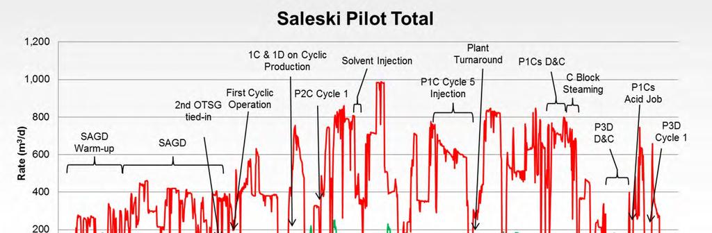
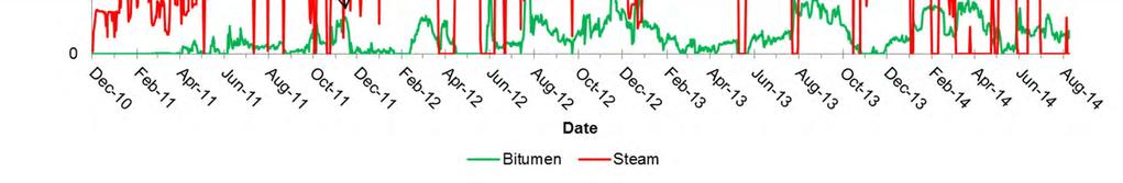
33 Summary of All Wells Section (7a) 4 well pairs operating as of August 31, (1D, 1C, 2C and 2D) 1D first steam in December, C first steam in January, C first steam in May, 2012 I2D first steam in August, 2012 P1C-s first steam in December 2013 P3D first steam in May 2014 Cumulative Injection/Production as of August 31, 2014 Steam Injected (m 3 ) Total Fluid Produced (m 3 ) Oil Produced (m 3 ) Water Produced (m 3 ) CSOR 1D Well Pair 101, ,220 17, , C Well Pair and P1C-s Well 181, ,541 24,872 78, I2D Well 84,592 20,670 2,396 18, C Well Pair 125, ,429 27,427 91, P3D Well 11,893 7,048 2,148 4, Pilot Total 505, ,908 74, , RF (Pilot Area) = 3.4% 33
34 Summary of All Wells Section (7a) C Well Pairs D Well Pairs 1C Well Pair Activity SAGD Apr - May 2011 (SAGD Warm-up) SAGD/Cycle #1 Nov - Dec 2011 SAGD Dec Jan 2012 (SAGD Test) Cycle #2 Jan - Apr 2012 Cycle #3 May - Aug 2012 Cycle #4 Aug Mar 2013 Cycle #5 Mar Dec 2013 P1C-s Well Activity Cycle #6 Dec 2013 Continuing past Aug C Well Pair Activity Cycle #1/Warm-Up May Jun 2012 Cycle #2 Jun - Oct 2012 Cycle #3 Oct May 2013 SAGD Test Jun - Jul 2013 Cycle #4 Jul - Nov 2013 Cycle #5 Nov 2013 Continuing past Aug D Well Pair Activity SAGD Dec Jan 2012 Cycle #1 Feb - May 2012 Cycle #2 Jul - Sept 2012 Cycle #3 Oct - Dec 2012 SAGD Test Dec Jan 2013 Cycle #4 Jan Continuing past Aug 2014 I2D Well Activity Cycle #1/Warm-Up Aug Nov 2012 Cycle #2 Nov - Jan 2013 Cycle #3 Jan May 2013 Cycle #4 Aug 2013 Jan 2014 Cycle #5 Jan Continuing past Aug 2014 P3D Well Activity Cycle #1/Warm-Up May Jul 2014 Cycle #2 Jul Aug 2014 Cycle #3 Sept continuing past Sept 2014
35 Scheme Performance Section (7a) 35

36 Scheme Performance Section (7a) 36


37 Scheme Performance Section (7a) 37

38 Scheme Performance Section (7a) 38

39 Scheme Performance Section (7a) 39

40 Scheme Performance Section (7a) 40

41 Scheme Performance Section (7a) 41

42 Scheme Performance Section (7a) 42
43 Scheme Performance Section (7a) Well trajectory has resulted in production challenges from this well 43

44 Scheme Performance Section (7a) 44
45 Scheme Performance Section (7a) 45
46 Scheme Performance Section (7a) 46
47 Summary of Key Insights Section (7f) Production estimation by manual cut and coriolis meter has proven reliable for monthly prorating. Progressive cavity pumps can remain in the well during steam injection reducing the need for a workover prior to production. Near balanced drilling reduces losses and formation damage in the lateral section and increases overall injectivity and productivity. C-SAGD operation is a more efficient early life recovery method than SAGD in the Grosmont. Horizontal wells in the Grosmont produce with minimal fines production both from lined and open hole horizontal wells. Production rates from the Pilot demonstrate commercial viability of the Grosmont. Communication between the Grosmont C and D continues to be enhanced through C-SAGD. 47
48 Production Forecast and Future Plans Subsurface Section (8) Continue to utilize C-SAGD operation. Continue use and optimization of mini-cycles at P1D. Continue testing of block steaming C wells. Future diluent co-injection in the Grosmont D to understand enhanced recovery. Addition of top injection in the C to understand later life recovery mechanism post C-SAGD. Testing of electrical submersible pump(s). Drilling of top injector (T1C) will provide opportunity to optimize near balanced and lost circulation drilling strategy prior to Phase 1. 48
49 VALUE I GROWTH I INNOVATION Subsection Surface Operations, Compliance, and Issues Not Related to Resource Evaluation and Recovery September 2014


50 Detailed Plot Plan Section (1a) Addition of P3D Well MR Version 2.0 Install Cathodic Protection System Addition of Quench Water Lines 50


51 Saleski Pilot Plant Progress Plant construction is complete with solvent capabilities Sept 2012 July 2011 August
 Block flow diagram is the same as submitted in the application with the")
52 Simplified Plant Schematic Section (1b) Block flow diagram is the same as submitted in the application with the exception of a few minor material balance corrections 52
53 Rationale for Modifications Section (1b) Cathodic protection system added to protect underground piping for several lines, most notably the new steel disposal line to 5-23, and the fuel gas line. Quench water system installed and tied in for each producing well to help manage downhole subcool issues and steam flashing up the casing. Replaced original version installed in 2011 of MR (Magnetic Resonance) water cut meter with second generation. Construction of P3D surface piping, installation of wellhead, and tie in to rest of surface facility. 53
54 Facility Performance Section (2) Plant has been operating since December No major facilities issues encountered during August August Plant has been operating smoothly. 54
55 Plant Performance Section (2 a-b) a: Bitumen Treatment Consistent treatment of produced bitumen has been achieved with BS&W of <0.5 % and density of 960 kg/m 3. b: Water Treatment Treatment of source water has been as expected. 55
56 Plant Performance Section (2 c-d) c: Steam Generation Two 50 MMBTU OTSG on site» Second OTSG started in December 2011 and operated at full capacity in April Total output of 1,000 m 3 /d CWE (800 m 3 /d CWE dry steam, 78-80% quality). Continued utilization of dry steam injection for C-SAGD wells. Utilization of OTSGs are intermittent due to cyclic operation. d: Power Generation/Consumption Laricina generates its own power on site. 2 x 1,400 kw natural gas driven generators. Only running one generator (approx. 160 x 10 3 m 3 /month). 56
57 Fuel Gas Consumption Section (2e) 4,000 3,500 3,000 Volume (1,000 m 3 ) 2,500 2,000 1,500 1, Jan 13 Mar 13 May 13 Jul 13 Sep 13 Nov 13 Jan 14 Mar 14 May 14 Jul 14 Date FG to Power Gens FG to OTSGs FG to Process Vessels/Wells FG to Other User (building heat, tank, blankets, flare purge) FG to Germain during TCPL line breakage Fuel gas transfer from Saleski Pilot to Germain Commercial Development during TransCanada Pipeline (TCPL) fuel gas line breakage and repair. 57
58 Energy Intensity; GJ/m 3 bitumen produced 350 Energy Intensity 300 Intensity (GJ/m 3 bitumen) Aug 13 Sep 13 Oct 13 Nov 13 Dec 13 Jan 14 Feb 14 Mar 14 Apr 14 May 14 Jun 14 Jul 14 Aug 14 Date Energy Intensity 58


59 Plant Flared Volumes *Total purge fuel gas is ~6,000-10,000 m 3 per month Temporary approval in March 2014 to flare 5,000m 3 /d Amended licence in July 2014 to flare 11,000 m 3 /d 59
60 Summary of Environmental Greenhouse Gas Emissions Section (2 f) Laricina Saleski GHG threshold for reporting both provincially & federally is 50,000 tonnes CO 2 e per year. GHG emissions reported to NPRI for 2013: NO x - 28 tonnes/year CO 27 tonnes/year Laricina has once again participated in NPRI and CAPP Responsible Canadian Energy reporting 60
61 Measurement and Reporting Section (3a,b) Production Measurement Proration Factors: Reconciled according to approved MARP (using inventory change, receipts and dispositions)» Prorated to daily water cut and coriolis emulsion flow meters» Multiple manual water cuts taken each day per producing well to prorate daily production. Monthly Water Proration Aug. Sep. Oct. Nov. Dec. Jan. Feb. Mar. Apr. May Jun. Jul. Aug Oil Proration
62 Measurement and Reporting continued Section (3c,d) Optimization Currently conducting trials of Perm Inc. s Magnetic Resonance (MR) continuous BS&W meter and AGAR s Multiphase Flow Meter (MPFM- 50). Meters are installed in series on a test loop coming off the main emulsion header shared by 3 wells (P1D, P1C-s, and P2C). Test times optimized per number of producing wells at one time (target 12 and 24 hour tests). 62
63 Measurement and Reporting continued Section (3c,d) Water transferred from the Saleski Facility to Germain: Total of 1,100 m 3 of disposal water was requested and approved from Alberta Environment and Water Act for transfer from the Saleski Pilot to the Germain Phase 1 CPF over a 120 day start-up period commencing June 7, In November and December 2013 * Laricina received a TDL to divert up to 10,000m 3 of boiler feed water from Saleski to the Germain to assist with Germain steam generation. The TDL expired in February In March 2014 Laricina applied and received a TDL to divert up to 15,000 m 3 of boiler feed water from Saleski to the Germain. The licence expires in March No fluids under this approval have been transferred to Germain as of yet. *TransCanada Fuel Gas Pipeline outage 63
 5 23 DW 2 26 DW Licensed Source Water Volumes: 5-23 392 m 3 /day 13-23 221 m 3 /day 14-24 711 m 3 /day 10-26 336 m 3 /day 07-20 264 m 3 /day 1F1/02-26 91 m 3 /day")
64 Source and Disposal Well Locations Section (4a,g) 5 23 DW 2 26 DW Licensed Source Water Volumes: m 3 /day m 3 /day m 3 /day m 3 /day m 3 /day 1F1/ m 3 /day 1F2/ m 3 /day 102/5-23 disposal well added in June 2012 DW 102/5-23 Total Annual License: 401,000 m 3 average of 1,100 m 3 /day 64
65 Update: 1F2/ W4M GW Sampling Groundwater samples were taken to establish a baseline average 95% confidence interval of baseline average is the target limit Test results in red are exceedances of target limit Target limit is a statistically determined range and is the expected background concentration Threshold is the highest of either Target Limit or Tier 1 Guidelines Sample Date Indicator Mar Feb Sep Oct May Oct May Oct May Target Limit (mg/l) Tier 1 Guidelines (mg/l) Threshold (mg/l) Benzene (mg/l) < Toluene (mg/l) < Ethylbenzene (mg/l) < < < < < < Xylene (mg/l) <
66 Possible Source of BTEX Exceedance of BTEX was observed before commencement of operations at the Pilot (December 2010). Two possible sources:» From lubricants introduced during well completion and or maintenance.» Due to sampling methods (purging of well not possible). 66
67 Monitoring Plans: 1F2/ W4M 1F2/2-26 will be sampled twice a year and tested for BTEX Sampling results are submitted to AER annually. Will be flagged for attention to trends where exceedences occur the in annual report to AER. If BTEX levels exceed threshold limits then the GMP Response Plan will be activated. GMP Response Plan includes:» Wells that exceed threshold will be re-sampled and re-tested.» If Threshold Limits continue to be exceeded then a time series review is conducted to determine any trends.» If a trend is detected then a source identification study is initiated to determine the source and source mitigation. 67
68 Water Sources and Uses Section (4a-d) Diversion licence (# ) from AER for 7 Grand Rapids source water wells: Water Source Well Volumes (m 3 ) Aug Sep Oct Nov Dec Jan Feb Mar Apr May Jun Jul Aug W4 13,648 13,940 14,533 13,276 14,906 13,603 12,421 9,497 12,647 12,486 12,229 1, W4 2,366 1,936 1,079 1,467 2, , W4 7,971 8,479 8,743 7,002 9,141 6,403 4,159 6,657 4,711 6,885 3,309 8,618 7, W4 5,829 7,750 7,805 7,340 8,176 7,206 6,472 6,327 3,853 2,331 2,812 7,489 6,622 1F1/ W F2/ W W4/ Total Water source volumes are below the annual allocation of 401,000 m SW well s statuses to be suspended. Produced water or blowdown is not recycled at the Pilot. 68
69 Water Sources and Uses Continued Section (4a-d) Total disposal volumes are at times greater than produced water volumes There were several periods when additional BFW was required to cool the process in the plant due to heat balance issues associated with nonalignment of cyclic steam injection and production cycles. Some BFW was circulated through offline OTSGs for freeze protection. These extra BFW volumes were not converted into steam and sent directly to disposal. 69
70 Disposal Well UWIs, Volumes, Pressures and Temperatures Section (h) 4 Class 1b Disposal Wells; Scheme Approval UWI Disposal Zone Maximum Wellhead Pressure (kpag) 100/ W4 Cooking Lake 3, / W4 Cooking Lake 3, W4 Grosmont A 3, W4 Grosmont A 3,500 Disposal Well Volumes (m 3 ) Aug Sep Oct Nov Dec Jan Feb Mar Apr May Jun Jul Aug 100/ W4 18,811 16,035 11,240 9,764 12,420 11,762 15,396 13,444 13,923 12,149 12,757 8,849 15, / W4 9,909 7,808 10,756 7,952 5,263 11,172 10,464 11,786 13,950 9,477 6,249 11,510 5, W , W
71 Disposal Well UWIs, Pressures and Temperatures Section (h) Average Monthly Disposal Pressure and Temperature 100/ W4/ Aug 13 Sep 13 Oct 13 Nov 13 Dec 13 Jan 14 Feb 14 Mar 14 Apr 14 May 14 Jun 14 Jul 14 Aug 14 Pressure (kpag) Temperature ( C) Date Aug 13 Sep 13 Oct 13 Nov 13 Dec 13 Jan 14 Feb 14 Mar 14 Apr 14 May 14 Jun 14 Jul 14 Aug 14 Pressure (kpag) Temperature ( C) Average Monthly Disposal Pressure and Temperature 100/ W4/00 Date Pressure Temperature Pressure Temperature Average Monthly Disposal Pressure and Temperature 102/ W4/ Aug 13 Sep 13 Oct 13 Nov 13 Dec 13 Jan 14 Feb 14 Mar 14 Apr 14 May 14 Jun 14 Jul 14 Aug 14 Pressure (kpag) Temperature ( C) Date Pressure Temperature *Note: Temperatures reported are from disposal tank not from each individual well. Temperature at well is 5-10 C cooler depending on the season. 71
72 Water Quality Assessments Section (4) Typical water quality assessments for produced water, source water and disposal fluids have been provided as Appendix E. 72
73 Sulphur Production Section (5b-d) Project is approved for 0.08 SO 2 tonnes/day. To date the facility has ranged from to 0.01 SO 2 tonnes/day. Passive sampling monitors continue to demonstrate that the Saleski Pilot is well within allowable limits for SO 2 and H 2 S. 73
74 Summary of Environmental Issues Section (6) Compliance issues related to regulatory approvals (e.g., EPEA, Sustainable Resource Development (SRD), Department of Fisheries and Oceans (DFO). In the table on the next slide are all the Q3/ and Q1/ noncompliance issues related to regulatory approvals. Over this time period 6 events have been reported to the AER. All the action items with respect to the non-compliances have been closed with the exception of This was a release of methanol during initial integrity testing of a Laricina pipeline. Laricina has been working with the AER field office to bring closure to this incident, with one more sampling event to be completed in September
75 Summary of Environmental Issues cont'd Section (6) Saleski Pilot Facility - EPEA Approval AER FIS Incident Number/AESRD Volume of Material Released Brief Description of Non-compliance Actions completed to correct the Non-compliance / L Amine release from a tote inside containment. / N/A Incorrect LSD on TDL / m 3 water from facility for rig water - no TDL OSUM (JV partner) used 7m 3 of disposal obtained to complete this activity / m 3 BFW release on lease at the facility / m 3 Disposal water release on and off lease - valve left open by operator / 300L Release of methanol water during liner hydrotest Release material removed and 7 day letter completed TDL revised and updated to reflect correct LSD TDL obtained for disposal water use in this activity. Free water removed, 7 day letter completed and incident reviewed to identify areas for improvement Free water removed, post sampling completed, 7 day letter submitted and incident reviewed to identify areas for improvement Final sampling event required by AER in Working with Bonnyville AER on final closure 75
76 Summary of Environmental Issues cont'd Section (6) Laricina continues to be very proactive in communications with regulatory agencies to maintain transparency and provide self disclosures and reporting of non-compliances where applicable. On February 14, 2014, Laricina received a letter from AER requesting an Oil Facility Detailed Operational Inspection (A1TY) Laricina Saleski Location: W4 Licence No.: F Laricina sent the information requested in a response on March 5 th, March 11 th and 12 th AER personnel conducted a detailed operations inspection of the Saleski Pilot Plant. 76
77 Summary of Environmental Issues cont'd Section (6) On March 27 th and 28 th Laricina received both high and low risk noncompliances from the detailed operations inspection as well as a number of follow up questions requesting further information. April 25 th and 30 th Laricina submitted the responses to the questions and actions for compliance to the high and low risk non-compliances and the follow up questions August 8 th, 2014 Laricina received the AER review and follow-up comments. September 5 th, Laricina filed a response to the letter received on August 5 th and awaits further instruction. 77
78 Progress and Results of Reclamation Programs Section (6e) Plant began operation in 2010 and there are no plans at this time for any pad abandonment All areas outside the CPF/well pad at Saleski have been successfully interim reclaimed 78
79 Statement Confirming Compliance Section (7&8) The Saleski Pilot Project is currently operating in accordance with approvals and regulatory requirements of the AER, AESRD, and DFO Previous non-compliance events and self-disclosures are listed under (6) 79
80 Future Plans Surface Section (9) Tie-in of top injector to Pilot facility Further testing of BS&W test devices Modifications of facility to accommodate ESP testing 80
81 Forward-looking Statements Advisory This Laricina Energy Ltd. (the Company ) presentation contains certain forward-looking statements. Forward-looking statements may include, but are not limited to, statements concerning estimates of exploitable original-bitumen-in-place, predicted recovery factors, steam-to-oil ratios and well production rates, estimated recoverable resources as defined below, expected regulatory filing, review and approval dates, construction and start-up timelines and schedules, company project potential production volumes as well as comparisons to other projects, statements relating to the continued overall advancement of the Company s projects, comparisons of recoverable resources to other oil sands projects, estimated relative supply costs, potential cost reductions, recovery and production increases resulting from the application of new technology and recovery schemes, estimates of carbon sequestration capacity, costs for carbon capture and sequestration and possible implementation schedule for carbon capture and sequestration processes or related emissions mitigation or reduction scheme and other statements which are not historical facts. You are cautioned not to place undue reliance on any forward-looking statements as there can be no assurance that the plans, intentions or expectations upon which they are based will occur. By their nature forward-looking statements involve numerous assumptions, known and unknown risks and uncertainties, both generally and specific, that contribute to the possibility that the predictions, forecasts, projections and other forward-looking statements will not occur. Although the Company believes that the expectations represented by such forward-looking statements are reasonable, there can be no assurance that such expectations will prove to be correct and, accordingly that actual results will be consistent with the forward-looking statements. Some of the risks and other factors that could cause results to differ materially from those expressed in the forward-looking statements contained in this presentation include, but are not limited to geological conditions relating to the Company s properties, the impact of regulatory changes especially as such relate to royalties, taxation and environmental changes, the impact of technology on operations and processes and the performance of new technology expected to be applied or utilized by the Company; labour shortages; supply and demand metrics for oil and natural gas; the impact of pipeline capacity, upgrading capacity and refinery demand; general economic business and market conditions and such other risks and uncertainties described from time to time in the reports and filings made with security regulatory authorities, contained in other disclosure documents or otherwise provided by the Company. Furthermore the forward-looking statements contained in this presentation are made as of the date hereof. Unless required by law the Company does not undertake any obligation to update publicly or to revise any of the included forward-looking statements, whether as a result of new information, future events or otherwise. The forward-looking statements contained in this presentation are expressly qualified by this advisory and disclaimer. 81
82 Significant Definitions In this presentation the reserve and recoverable resource numbers, along with the net present values given, are as defined in the report of GLJ Petroleum Consultants Ltd. ( GLJ ) regarding certain of Laricina s properties effective December 31, 2013, referred to herein (the GLJ Report ). Exploitable OBIP or Expl. OBIP refers to original-bitumen-in-place that is targeted for development using thermal recovery technologies. The best and high estimate of the Company s resources include contingent and prospective resources. Cont. or 2C and Pros. refer to contingent and prospective bitumen resources, respectively. Contingent resource values have not been risked for chance of development while prospective resource values have been risked for chance of discovery but not for chance of development. There is no certainty that it will be commercially viable to produce any portion of the contingent resources. There is no certainty that any portion of the prospective resources will be discovered or, if discovered, if it will be commercially viable to produce any portion of the prospective resources. 2P means proved plus probable reserves and 3P means proved plus probable plus possible reserves. SAGD means steam-assisted gravity drainage. C-SAGD means cyclic SAGD. SC-SAGD means solvent-cyclic SAGD. CSS means cyclic steam stimulation. The SC-SAGD best estimate technology sensitivity (Laricina technology sensitivity) net economic forecasts were prepared on Saleski-Grosmont and Germain-Grand Rapids based on SC-SAGD technology. SOR means steam-oil ratio. CSOR means cumulative steam-oil ratio. CDOR means calendar day oil rate. bbl means barrel. bn means billions. m means metres. mmbbl means millions of barrels. bbl/d means barrels per day. EIA means Energy Information Administration. NPV means net present value. m 3 means cubic metres. m 3 /d means cubic metres per day. kpa means kilopascal. Dkeff means Darcy s effective permeability. km 2 means square-kilometres. NPV10 means net present value, before tax, 10 percent discount. US$ means United States dollars. U.S. means United States of America. WTI means West Texas Intermediate. WCS means Western Canadian Select. PV10 means net present value before tax, 10 percent discount. Unless otherwise stated, all dollar amounts are shown in Canadian dollars (C$). 82
83 Contact Us Laricina Energy Ltd. 800, st Street SW Calgary, Alberta T2P 3L laricina@laricinaenergy.com 83

84 Appendices
85 Appendix A: Wellbore schematics and completions for observation wells including positioning relative to the trajectories of the production and injection wells. 85
86 Well Completions and Schematics Section (3b and 5a) ELEV (masl) Observation Well Construction Details 102/ W4 (P1Obs1) As of July 2009 DEPTH (mkb) Laricina Observation Well P1-Obs1 102/ W4 Grosmont C & D Formations Piezometer Thermocouple Borehole Diameter: 311 mm Surface Casing: mm Thread: ST&C Grade: H40 Thermal Cement Casing Shoe Piezometer # Grosmont 'D' Borehole Diameter: 200 mm Thermocouple Spacing: 3.0m 316m to 343m GL Thermocouple Spacing: 1m 346m to 355m GL Thermocouple Spacing: 2m 356m to 366m GL Piezometer # Grosmont 'D' Thermocouple Spacing: 1m 368m to 378m GL Piezometer # Production Casing: 114 mm Grosmont 'C' Thread: Tenaris Blue Grade: L80 Thermal Cement TD Borehole TD 86
87 Well Completions and Schematics Section (3b and 5a) ELEV (masl) Observation Well Construction Details 104/ W4 (P1Obs2) As of March 2010 DEPTH (mkb) Laricina Observation Well P1-Obs2 104/ W4 Grosmont C & D Formations Piezometer Thermocouple Borehole Diameter: 311 mm Surface Casing: mm Thread: ST&C Grade: H40 Thermal Cement Casing Shoe Borehole Diameter: 200 mm Piezometer # Grosmont 'D' Thermocouple Spacing: 3.0m Piezometer # m to 347m GL Grosmont 'D' Thermocouple Spacing: 1m Piezometer # m to 360m GL Grosmont 'D' Thermocouple Spacing: 2m 360m to 370m GL Piezometer # Grosmont 'C' Thermocouple Spacing: 1m 372m to 382m GL Piezometer # Production Casing: 114 mm Grosmont 'C' Thread: Tenaris Blue Grade: L80 Thermal Cement TD Borehole TD 87
88 Well Completions and Schematics Section (3b and 5a) ELEV (masl) Observation Well Construction Details 103/ W4 (P1Obs3) As of July 2009 DEPTH (mkb) Laricina Observation Well P1-Obs3 103/ W4 Grosmont C & D Formations Piezometer Thermocouple Borehole Diameter: 311 mm Surface Casing: mm Thread: ST&C Grade: H40 Thermal Cement Casing Shoe Borehole Diameter: 200 mm Piezometer # Grosmont 'D' Thermocouple Spacing: 3.0m Piezometer # m to 343m GL Grosmont 'D' Piezometer # Grosmont 'D' Thermocouple Spacing: 1m 346m to 355m GL Thermocouple Spacing: 2m 356m to 366m GL Piezometer # Grosmont 'C' Thermocouple Spacing: 1m 368m to 378m GL Piezometer # Production Casing: 114 mm Grosmont 'C' Thread: Tenaris Blue Grade: L80 Thermal Cement TD Borehole TD 88
89 Well Completions and Schematics Section (3b and 5a) ELEV (masl) Observation Well Construction Details 100/ W4 (P2Obs1) As of March 2010 DEPTH (mkb) Laricina Observation Well P2-Obs1 100/ W4 Grosmont C & D Formations Piezometer Thermocouple Borehole Diameter: 311 mm Surface Casing: mm Thread: ST&C Grade: H40 Thermal Cement Casing Shoe Borehole Diameter: 200 mm Piezometer # Grosmont 'D' Thermocouple Spacing: 3.0m Piezometer # m to 343m GL Piezometer # Grosmont 'D' Thermocouple Spacing: 1m 346m to 355m GL Thermocouple Spacing: 2m Piezometer # m to 366m GL Grosmont 'C' Thermocouple Spacing: 1m Piezometer # m to 378m GL Grosmont 'C' Production Casing: 114 mm Thread: Tenaris Blue Grade: L80 Thermal Cement TD Borehole TD 89
90 Well Completions and Schematics Section (3b and 5a) ELEV (masl) Observation Well Construction Details 106/ W4 (P2Obs2) As of March 2010 DEPTH (mkb) Laricina Observation Well P2-Obs2 106/ W4 Grosmont C & D Formations Piezometer Thermocouple Borehole Diameter: 311 mm Surface Casing: mm Thread: ST&C Grade: H40 Thermal Cement Casing Shoe Borehole Diameter: 200 mm Piezometer # Grosmont 'D' Thermocouple Spacing: 3.0m 318m to 348m GL Piezometer # Grosmont 'D' Piezometer # Grosmont 'D' Thermocouple Spacing: 1m 348m to 358m GL Thermocouple Spacing: 2m 358m to 368m GL Piezometer # Grosmont 'C' Thermocouple Spacing: 1m 370m to 380m GL Piezometer # Production Casing: 114 mm Grosmont 'C' Thread: Tenaris Blue Grade: L80 Thermal Cement TD Borehole TD 90
91 Well Completions and Schematics Section (3b and 5a) ELEV (masl) Observation Well Construction Details 102/ W4 (P2Obs3) As of July 2009 DEPTH (mkb) Laricina Observation Well P2-Obs3 102/ W4 Grosmont C & D Formations Piezometer Thermocouple Borehole Diameter: 311 mm Surface Casing: mm Thread: ST&C Grade: H40 Thermal Cement Casing Shoe Borehole Diameter: 200 mm Piezometer # Grosmont 'D' Thermocouple Spacing: 3.0m Piezometer # m to 343m GL Piezometer # Grosmont 'D' Thermocouple Spacing: 1m 346m to 355m GL Thermocouple Spacing: 2m Piezometer # m to 366m GL Grosmont 'C' Thermocouple Spacing: 1m Piezometer # m to 378m GL Grosmont 'C' Production Casing: 114 mm Thread: Tenaris Blue Grade: L80 Thermal Cement TD Borehole TD 91
92 Well Completions and Schematics Section (3b and 5a) ELEV (masl) Observation Well Construction Details 105/ W4 (P1-2 Obs2) As of March 2010 DEPTH (mkb) Laricina Observation Well P1-2-Obs2 105/ W4 Grosmont C & D Formations Piezometer Thermocouple Borehole Diameter: 311 mm Surface Casing: mm Thread: ST&C Grade: H40 Thermal Cement Casing Shoe Borehole Diameter: 200 mm Piezometer # Grosmont 'D' Thermocouple Spacing: 3.0m 318m to 348m GL Piezometer # Grosmont 'D' Piezometer # Grosmont 'D' Thermocouple Spacing: 1m 348m to 358m GL Thermocouple Spacing: 2m 358m to 368m GL Piezometer # Grosmont 'C' Thermocouple Spacing: 1m 370m to 380m GL Piezometer # Production Casing: 114 mm Grosmont 'C' Thread: Tenaris Blue Grade: L80 Thermal Cement TD Borehole TD 92
93 Appendix B: Disposal and source water wellbore schematics and completions. 93
94 Well Completions and Schematics Section (3b and 5a) Disposal Well Construction and Completion Details 100/ W4 (Disposal Well) ELEV (masl) DEPTH (mkb) Ground Elev Laricina Disposal Well 100/ W4 Cooking Lake Formation Borehole Diameter: 311 mm Surface Casing: mm Thread: ST&C Grade: H40 Thermal Cement Base of Groundwater Protection for Grand Rapids Injection Tubing 89mm Fibreglass Casing Shoe Cooking Lake Formation Inhibited Fluid in annulus Borehole Diameter: 222 mm QDG Retrievable Packer Double Grip Production Packer mkb Perforations m 26 spm, 12 mm diameter Production Casing: mm Thread: Tenaris Blue Grade: L80 Thermal Cement PBTD Borehole TD 94
 Laricina Disposal Well 102/05-23-085-20W4")
95 Well Completions and Schematics Section (3b and 5a) Laricina Disposal Well 102/ W4 Cooking Lake Formation 95
96 Well Completions and Schematics Section (3b and 5a) Disposal Well Construction and Completion Details 100/ W4 (Disposal Well) ELEV (masl) DEPTH (mkb) Ground Level Laricina Disposal Well 100/ W4 Grosmont A Formation Borehole Diameter: 311 mm Surface Casing: mm Thread: ST&C Grade: H40 Thermal Cement Base of Groundwater Protection for Grand Rapids Injection Tubing 89mm Fibreglass Casing Shoe Grosmont A Inhibited Fluid in annulus Borehole Diameter: 222 mm QDG Retrievable Packer Double Grip Production Packer 427 mkb Perforations m 26 spm, 12 mm diameter Grosmont 'C' Production Casing: mm Thread: Tenaris Blue Grade: L80 Thermal Cement PBTD Borehole TD 96
97 Well Completions and Schematics Section (3b and 5a) Disposal Well Construction and Completion Details 100/ W4 (Disposal Well) ELEV (masl) DEPTH (mkb) Ground Level Laricina Disposal Well 100/ W4 Grosmont A Formation Borehole Diameter: 311 mm Surface Casing: mm Thread: ST&C Grade: H40 Thermal Cement Base of Groundwater Protection for Grand Rapids Injection Tubing 89mm Fibreglass Casing Shoe Inhibited Fluid in annulus Borehole Diameter: 222 mm Grosmont A Perforations: mKB mKB mKB 26 spm, 12 mm diameter Grosmont 'C' Production Casing: mm Thread: Tenaris Blue Grade: L80 Thermal Cement PBTD Borehole TD 97
98 Well Completions and Schematics Section (3b and 5a) Typical Water Source Well Construction and Completion Details Laricina Water Source Wells Typical Schematic Lower Grand Rapids Formation ELEV (masl) DEPTH (mkb) Subsurface Seal Base Stickup: 1.2 m Borehole Diameter: 438 mm Cement Grout Conductor Pipe Size: 324 mm UWIs: 1F2/ W4/00 1F1/ W4/00 1F1/ W4/00 1F1/ W4/00 1F1/ W4/00 1F1/ W4 1F2/ W4 Borehole Diameter: mm Static Water Thermal Cement Level Production Casing: mm I.D. Grade: H-40 Top of K-Packer Top of Screen Casing Shoe Stainless Steel Outer Screen: mm (8.550") O.D. Base Pipe: mm (5.500") O.D. Base Pipe Open Area: 9.8% Pre-Packed Sand: 16/30 Silica Screen Size: 0.018" - Slot Screen Open Area: 18% Borehole Diameter: mm (8.75") *Borehole may be under-reamed to a larger diameter if difficulty installing screen. Circulation Valve Bottom of Screen Total Borehole TD Depth 98
99 Appendix C: Observation well s piezometer and temperature plots. Data in corresponding excel file Monthly injection pressure data in corresponding excel file. 99
100 Observation Well s Piezometer Data Section (5d i) Pressures in Observation Well P1Obs1 TVD (m) Pressure (kpa) Value of 0 kpa is an error. Aug 13 Sep 13 Oct 13 Nov 13 Dec 13 Jan 14 Feb 14 Mar 14 Apr 14 May 14 Jun 14 Jul 14 Aug
101 Observation Well s Piezometer Data Section (5d i) Pressures in Observation Well P1Obs Pressure (kpa) Aug 13 Sep 13 Oct 13 Nov 13 Dec 13 Jan 14 TVD (m) Feb 14 Mar 14 Apr 14 May 14 Jun 14 Jul 14 Aug
102 Observation Well s Piezometer Data Section (5d i) Pressures in Observation Well P1Obs3 TVD (m) Pressure (kpa) Value of kpa is an error. Aug 13 Sep 13 Oct 13 Nov 13 Dec 13 Jan 14 Feb 14 Mar 14 Apr 14 May 14 Jun 14 Jul 14 Aug
103 Observation Well s Piezometer Data Section (5d i) Pressures in Observation Well P2Obs Pressure (kpa) Aug 13 Sep 13 Oct 13 Nov 13 Dec 13 Jan 14 TVD (m) Feb 14 Mar 14 Apr 14 May 14 Jun 14 Jul 14 Aug
104 Observation Well s Piezometer Data Section (5d i) Pressures in Observation Well P2Obs Pressure (kpa) Aug 13 Sep 13 Oct 13 Nov 13 Dec 13 Jan 14 TVD (m) Feb 14 Mar 14 Apr 14 May Value of kpa is an error. Jun 14 Jul 14 Aug
105 Observation Well s Piezometer Data Section (5d i) Pressures in Observation Well P2Obs3 Pressure (kpa) Aug Sep Oct Nov Dec Jan 14 TVD (m) Value of kpa is an error. Feb 14 Mar Apr May Jun Jul Aug
106 Observation Well s Piezometer Data Section (5d i) Pressures in Observation Well P12Obs Pressure (kpa) Aug 13 Sep 13 Oct 13 Nov 13 Dec 13 Jan 14 TVD (m) Feb 14 Mar 14 Apr 14 May 14 Jun 14 Jul 14 Aug
107 Observation Well s Thermocouple Data Section (5d ii) Temperatures in Observation Well P1Obs Temperature ( C) Aug 13 Sep 13 Oct 13 TVD (m) Nov 13 Dec 13 Jan 13 Feb 13 Mar 13 Apr May 14 Jun 14 Jul 14 Aug
108 Observation Well s Thermocouple Data Section (5d ii) Temperatures in Observation Well P1Obs Temperature ( C) Aug 13 Sep 13 Oct 13 TVD (m) Nov 13 Dec 13 Jan 13 Feb 13 Mar 13 Apr May 14 Jun 14 Jul 14 Aug
109 Observation Well s Thermocouple Data Section (5d ii) Temperatures in Observation Well P1Obs Temperature ( C) Aug 13 Sep 13 Oct 13 TVD (m) Nov 13 Dec 13 Jan 13 Feb 13 Mar 13 Apr May 14 Jun 14 Jul 14 Aug
110 Observation Well s Thermocouple Data Section (5d ii) Temperatures in Observation Well P2Obs1 TVD (m) Temperature ( C) Aug 13 Sep 13 Oct 13 Nov 13 Dec 13 Jan 13 Feb 13 Mar 13 Apr 14 May 14 Jun 14 Jul 14 Aug
111 Observation Well s Thermocouple Data Section (5d ii) Temperatures in Observation Well P2Obs Temperature ( C) Aug 13 Sep 13 Oct 13 TVD (m) Nov 13 Dec 13 Jan 13 Feb 13 Mar 13 Apr May 14 Jun 14 Jul 14 Aug
112 Observation Well s Thermocouple Data Section (5d ii) Temperatures in Observation Well P2Obs Temperature ( C) Aug 13 Sep 13 Oct 13 TVD (m) Nov 13 Dec 13 Jan 13 Feb 13 Mar 13 Apr May 14 Jun 14 Jul 14 Aug
113 Observation Well s Thermocouple Data Section (5d ii) Temperatures in Observation Well P12Obs2 TVD (m) Temperature ( C) Aug 13 Sep 13 Oct 13 Nov 13 Dec 13 Jan 13 Feb 13 Mar 13 Apr 14 May 14 Jun 14 Jul 14 Aug
114 Appendix D: Scheme injection and production data. 114
115 Monthly Injection and Production Data for 1D Well Pair Section (7a ii) D1 Well Pair Month Steam Injected Bitumen Produced Water Produced (Sm 3 ) (m 3 ) (Sm 3 ) Aug ,541 Sep ,811 Oct-13 1, ,531 Nov ,187 Dec ,167 Jan ,273 11,912 Feb ,675 Mar-14 2, ,819 Apr ,580 May Jun-14 3, Jul ,631 Aug ,
116 Monthly Injection and Production Data for 1C Well Pair/P1C-s Well Section (7a ii) 1C Well Pair/ P1C-s Well Month Steam Injected Bitumen Produced Water Produced (Sm 3 ) (m 3 ) (Sm 3 ) Aug ,598 8,210 Sep ,373 1,827 Oct-13 2, Nov-13 9, Dec-13 3, Jan-14 6, Feb ,110 2,388 Mar ,004 2,475 Apr ,408 2,308 May ,206 Jun ,056 Jul ,765 Aug
117 Monthly Injection and Production Data for 2C Well Pair Section (7a ii) 2C Well Pair Month Steam Injected Bitumen Produced Water Produced (Sm 3 ) (m 3 ) (Sm 3 ) Aug-13 9,380 1,521 1,808 Sep ,757 3,927 Oct ,968 3,991 Nov-13 6, ,035 Dec-13 18, Jan-14 7, ,199 Feb ,703 6,101 Mar ,429 3,772 Apr ,042 2,729 May ,267 Jun ,478 Jul ,002 2,434 Aug ,
118 Monthly Injection and Production Data for I2D Well Section (7a ii) I2D Well Month Steam Injected Bitumen Produced Water Produced (Sm 3 ) (m 3 ) (Sm 3 ) Aug-13 4, Sep-13 15, Oct-13 15, Nov Dec ,381 Jan-14 1, Feb-14 8, Mar-14 3, Apr May Jun ,663 Jul ,325 Aug
119 Monthly Injection and Production Data for P3D Well Section (7a ii) P3D Well Month Steam Injected Bitumen Produced Water Produced (Sm 3 ) (m 3 ) (Sm 3 ) Aug Sep Oct Nov Dec Jan Feb Mar Apr May-14 1, Jun-14 3, ,120 Jul-14 6, Aug ,
120 Appendix E: Water Quality Assessments 120

121 Source Water Analysis 121

122 Disposal Water Analysis 122
Progressing C-SAGD recovery of bitumen from the Grosmont D reservoir
 Progressing C-SAGD recovery of bitumen from the Grosmont D reservoir LARICINA ENERGY Steve Brand P. Eng. WHOC15-280 Organized by: Outline Project overview 1D experience and knowledge gained Early cycle
Seal Main HCSS Pilot Subsurface Review
 Seal Main HCSS Pilot Subsurface Review Subsurface Agenda 1. Background 2. Geology 3. Drilling and Completions 4. Artificial Lift 5. Well Instrumentation 6. 4D Seismic 7. Scheme Performance 8. Future Plans
Pelican Lake SAGD Pilot Approval 11469A 2011 Update. ERCB Offices March 21, 2012.
 Approval 11469A 2011 Update ERCB Offices March 21, 2012. Introduction and Overview Introduction Subsurface Issues Related to Resource Evaluation and Recovery Directive 054, Section 3.1.1 Surface Operations,
Seal Main HCSS Pilot Approval Annual Performance Presentation
 Seal Main HCSS Pilot Approval 11377 Annual Performance Presentation 11-Feb-2015 Agenda Introductions Seal Main Horizontal Cyclic Steam Stimulation (HCSS) Pilot Subsurface Surface Harmon Valley South HCSS
Alberta Energy Regulator Suite 1000, Street SW Calgary, Alberta T2P 0R4 Attention: Steve Thomas, P.Eng., Section Leader In-Situ Oil Sands
 East Tower, 5 th Ave Place Suite 800, 425-1 st Street S.W. Calgary, Alberta T2P 3L8 Tel: 403-750-0810 Fax: 403-263-0767 www.laricinaenergy.com August 7, 2013 Alberta Energy Regulator Suite 1000, 250 5
Harmon Valley South HCSS Pilot Approval Annual Performance Presentation
 Harmon Valley South HCSS Pilot Approval 11895 Annual Performance Presentation 11-Feb-2015 Subsurface Agenda 1. Background 2. Geology 3. Drilling and Completions 4. Artificial Lift 5. Well Instrumentation
JAPAN CANADA OIL SANDS LTD. HANGINGSTONE DEMO PROJECT 2004 Presented on Monday, March 7, 2005 Presentation Outline
 Thermal In-Situ Scheme Progress Report JAPAN CANADA OIL SANDS LTD. HANGINGSTONE DEMO PROJECT 2004 Presented on Monday, March 7, 2005 Presentation Outline 1. Introduction Project Background, Activity Summary
Pelican Lake SAGD Pilot
 Pelican Lake SAGD Pilot AER Approval 11469B April 16, 2015 Annual Update January 1, 2014 December 31, 2014 Disclaimer This Cenovus Pelican Lake SAGD Pilot January 1, 2014 to December 31, 2014 Update (
Air injection & displacement for recovery with oil horizontal (AIDROH) project Approval #11618 Performance presentation
 project Approval #11618 Performance presentation") Air injection & displacement for recovery with oil horizontal (AIDROH) project Approval #11618 Performance presentation AER Office Calgary March 2014 Advisory This document contains forward-looking information
Air injection & displacement for recovery with oil horizontal (AIDROH) project Approval #11618 Performance presentation AER Office Calgary March 2014 Advisory This document contains forward-looking information
Air injection & displacement for recovery with oil horizontal (AIDROH) project Approval #11618 Performance presentation
 project Approval #11618 Performance presentation") Air injection & displacement for recovery with oil horizontal (AIDROH) project Approval #11618 Performance presentation ERCB offices Calgary February 2013 Advisory This document contains forward-looking
Air injection & displacement for recovery with oil horizontal (AIDROH) project Approval #11618 Performance presentation ERCB offices Calgary February 2013 Advisory This document contains forward-looking
6 DRILLING AND COMPLETIONS
 Cenovus FCCL Ltd. 6-1 Drilling and Completions 6 DRILLING AND COMPLETIONS 6.1 OVERVIEW This section contains information about the drilling and completion of wells within the CLTP. Well counts, locations
January 2011 to September 2012 Kirby ERCB Directive 54 Annual Performance Presentation
 January 2011 to September 2012 Kirby ERCB Directive 54 Annual Performance Presentation September 26, 2012 Premium Value Defined Growth Independent OUTLINE PAGE # Kirby Approval 11475 (South) 5-69 Background
Murphy Oil Company LTD.
 Murphy Oil Company LTD. Seal Polymer Pilot Scheme Approval No. 11320B Annual ERCB Progress Presentation June 3, 2013 1 Agenda Subsurface Surface Conclusions 2 Subsurface Background Geology Drilling & Completions
Penn West Petroleum Ltd. Seal Main HCSS Pilot and Harmon Valley South Annual ERCB Progress Presentation
 Penn West Petroleum Ltd. Seal Main HCSS Pilot and Harmon Valley South Annual ERCB Progress Presentation 2013-01-17 Advisory General: This presentation is for information purposes only and is not intended
Cenovus EnCAID approval #10440J Performance presentation
 Cenovus EnCAID approval #10440J Performance presentation Claire Hong Staff Production/Completion Engineer Dubert Gutierrez Sr. Reservoir Engineer AER offices Calgary February 2015 Advisory This document
HILDA LAKE SAGD PILOT PERFORMANCE SUMMARY 2004 AEUB PRESENTATION BLACKROCK VENTURES INC
 HILDA LAKE SAGD PILOT PERFORMANCE SUMMARY 2004 AEUB PRESENTATION BLACKROCK VENTURES INC FEBRUARY, 2004 HILDA LAKE SAGD PILOT PERFORMANCE SUMMARY 2003-2004 PRESENTATION OUTLINE PRODUCTION SUMMARY P1 AND
2017 Directive 54 Performance Presentation
 2017 Directive 54 Performance Presentation Seal Scheme Approval No. 11320E September 2017 Agenda Subsurface 1. Overview 2. Geology / Geoscience 3. Drilling and Completions 4. Scheme Performance 5. Injection
Annual Performance Presentation
 Annual Performance Presentation In Situ Oil Sands Schemes 9673 / 10147 / 10423 / 10787 March 2014 Premium Value Defined Growth Independent Agenda Current Approvals Geological Overview Drilling, Completions,
2018 Directive 054 Performance Presentation
 2018 Directive 054 Performance Presentation Seal Scheme Approval No. 11320F September 2018 Agenda Subsurface 1. Overview 2. Geology / Geoscience 3. Drilling and Completions 4. Scheme Performance 5. Injection
Sunshine Oilsands Ltd. BA Code A2TF WEST ELLS SAGD. Scheme No E AER In Situ Performance Presentation 2017
 Sunshine Oilsands Ltd. BA Code A2TF WEST ELLS SAGD Scheme No. 11764E AER In Situ Performance Presentation 2017 Presenters Qi Jiang, P. Eng., Ph.D. Chief Technology Officer Eugene Dembicki, M.Sc., P.Geol.
Pengrowth Energy Corporation Lindbergh SAGD Project 2013 Annual Performance Presentation Scheme Approval No. 6410I.
 Pengrowth Energy Corporation Lindbergh SAGD Project 2013 Annual Performance Presentation Scheme Approval No. 6410I October 1, 2013 Introduction and Overview Introduction Subsurface Issues Related to Resource
VSD is a commercially proven technology for bitumen recovery that is used worldwide and in Western Canada by other operators.
 RECOVERY PROCESS Section 4.1 APPLICATION FOR APPROVAL OF THE CARMON CREEK PROJECT VOLUME 1: PROJECT DESCRIPTION SELECTED RECOVERY PROCESS 4.1.1 SELECTION BASIS Vertical steam drive (VSD), complemented
Annual Performance Presentation
 Annual Performance Presentation In Situ Oil Sands Schemes 9673 / 10147 / 10423 / 10787 April 2017 Premium Value Defined Growth Independent Agenda Current Approvals Geological Overview Drilling, Completions,
Evaluation of Recovery Technology for the Grosmont Carbonate Reservoir
 CIPC Paper 2009-067 Evaluation of Recovery Technology for the Grosmont Carbonate Reservoir Qi Jiang Jian-Yang Yuan Jen Russel-Houston Bruce Thornton Andrew Squires Osum Oil Sands Corp. Outline Geology
Orion In Situ Oil Sands 2015 Progress Update. Presented May 25, 2016
 Orion In Situ Oil Sands 2015 Progress Update Presented May 25, 2016 Agenda Introduction Geoscience Scheme Performance Surface Operations Compliance Future Plans 2 Project Location Osum Production Corp.
Outline of Presentation
 4 th Wellbore Integrity Network Meeting Monitoring i of Wellbore Performance at Penn West CO 2 -EOR Rick Chalaturnyk Geological Storage Research Group Department of Civil and Environmental Engineering
Thermal In-Situ Scheme Progress Report for 2016 Japan Canada Oil Sands Limited Hangingstone. Approval No (Demonstration Project)
") Thermal In-Situ Scheme Progress Report for 2016 Japan Canada Oil Sands Limited Hangingstone Approval No. 8788 (Demonstration Project) 1. Background Hangingstone Expansion Project 2. Subsurface Geosciences
Thermal In-Situ Scheme Progress Report for 2016 Japan Canada Oil Sands Limited Hangingstone Approval No. 8788 (Demonstration Project) 1. Background Hangingstone Expansion Project 2. Subsurface Geosciences
Examining Reservoir Water Retention During SAGD. Thursday January 31 st, 2013
 Examining Reservoir Water Retention During SAGD Thursday January 31 st, 2013 Forward-looking information and advisories This presentation contains "forward-looking information" within the meaning of applicable
Annual Surmont SAGD Performance Review Approvals 9426, 11596, and April 6, 2016 Calgary, Alberta, Canada
 Annual Surmont SAGD Performance Review Approvals 9426, 11596, and 9460 April 6, 2016 Calgary, Alberta, Canada Introduction, Overview and Highlights Subsection 3.1.1 (1) Ownership and Approvals Ownership
JAPAN CANADA OIL SANDS HANGINGSTONE SAGD PROJECT
 Public Disclosure Document for the proposed JAPAN CANADA OIL SANDS HANGINGSTONE SAGD PROJECT May 7 th, 2008 I. INTRODUCTION Japan Canada Oil Sands Limited (JACOS) continues to evaluate the development
Aquistore. Saskatchewan s Deep Saline CO 2 Storage Research Project. April 19, Presented by Kyle Worth, P.Eng., PMP to INRS, Quebec City
 Aquistore Saskatchewan s Deep Saline CO 2 Storage Research Project Presented by Kyle Worth, P.Eng., PMP to INRS, Quebec City April 19, 2012 Petroleum Technology Research Centre Mission: To develop world-leading
Measurement Schematics & Facility Delineation Requirements Required by September 11, 2014
 Alberta Energy Regulator (AER) Directive 017 - Measurement Requirements for Oil and Gas Operations Version - September 2012 Measurement Schematics & Facility Delineation Requirements Required by September
Cold Lake expansion project
 Cold expansion project Initial project description Plain language summary March 2016 Our commitment Imperial Oil Limited s success depends on our ability to maintain an open dialogue with, and ongoing
SPE Abstract. Introduction
 SPE 149944 Succesful Application of Metal PCP Rechnology to Maximize Oil Recovery in SAGD Process R. Arystanbay, SPE, W. Bae, SPE, Huy X. Nguyen, SPE, Sejong University; S. Ryou, SPE, W. Lee, T. Jang,
LARICINA ENERGY LTD. STONY MOUNTAIN PIPELINE PROJECT DESCRIPTION DOCUMENT FEBRUARY 2012
 LARICINA ENERGY LTD. STONY MOUNTAIN PIPELINE PROJECT DESCRIPTION DOCUMENT FEBRUARY 2012 01 STONY MOUNTAIN PIPELINE Laricina will develop and follow an environmental protection plan that meets or exceeds
GROUSE GROUSE IN SITU OIL SANDS PROJECT. Proposed Development Plan. Plain Language Project Summary
 GROUSE Proposed Development Plan GROUSE IN SITU OIL SANDS PROJECT Plain Language Project Summary ABOUT CANADIAN NATURAL WHO WE ARE Canadian Natural Resources Limited (Canadian Natural) is a senior independent
Oil Sands Development in Canada by SAGD - Further Challenges to Improve Efficiency -
 Oil Sands Development in Canada by SAGD - Further Challenges to Improve Efficiency - Nov-29, 2017 JAPEX (Japan Petroleum Exploration Co., Ltd) Canada Oil Sands Project Dept. Tanetomo (Tom) Izumi Japan
MONTHLY UPDATE PRIMROSE OIL SANDS FLOW TO SURFACE
 1 Introduction MONTHLY UPDATE PRIMROSE OIL SANDS FLOW TO SURFACE April 9, Primrose/Wolf Lake Oil Sands Project (PAW) is a thermal in situ operation located approximately 65 km north of Bonnyville and about
MONTHLY UPDATE PRIMROSE OIL SANDS FLOW TO SURFACE
 1 Introduction MONTHLY UPDATE PRIMROSE OIL SANDS FLOW TO SURFACE March 3, 2014 Primrose/Wolf Lake Oil Sands Project (PAW) is a thermal in situ operation located approximately 65 km north of Bonnyville
2012 Annual Performance Presentation McKay River Thermal Project
 2012 Annual Performance Presentation McKay River Thermal Project Outline Introductions 3.1.1 Subsurface Overview Related to Resource Evaluation and Recovery 3.1.2 Surface Operations, Compliance, and Issues
Ron Stefik, Eng.L. Supervisor, Reservoir Engineering Oil and Gas Commission Attachment COMMISSION. T F
 COMMISSION June 10, 2016 3600-2800/2850-32640-02 Nicholas Haddow, Regulatory Specialist Aqua Terra Water Management Inc. #108, 32 Burnt Lake Crescent Red Deer, AB T4S 0K6 Dear Mr. Haddow: RE: PRODUCED
Grizzly Oil Sands. Algar Lake SAGD Project 2015 In Situ Performance Presentation Scheme Approval No C May 13, 2015
 Algar Lake SAGD Project 2015 In Situ Performance Presentation Scheme Approval No. 11688C May 13, 2015 Outline and Presenters Introduction and Project Background Alan Stroich Geoscience Jinxiu Qi Drilling
Should you have any questions, please contact Michelle Harding at (250) or the undersigned at (250) Sincerely,
 or the undersigned at (250) Sincerely,") COMMISSION April 19, 2016 3600-2800-32640-02 Nicholas Haddow, Regulatory Specialist Aqua Terra Water Management Inc. #108, 32 Burnt Lake Crescent Red Deer, AB T4S 0K6 Dear Mr. Haddow: RE: PRODUCED WATER
COMMISSION April 19, 2016 3600-2800-32640-02 Nicholas Haddow, Regulatory Specialist Aqua Terra Water Management Inc. #108, 32 Burnt Lake Crescent Red Deer, AB T4S 0K6 Dear Mr. Haddow: RE: PRODUCED WATER
Draft Directive 051. Wellbore Injection Requirements. Contents. Revised edition August 14, Replaces previous edition issued March 1994.
 Draft Directive 051 Revised edition August 14, 2012. Replaces previous edition issued March 1994. Wellbore Injection Requirements The Energy Resources Conservation Board (ERCB/Board) has approved this
CAPROCK INTEGRITY FOCUS Analyzing How To Utilize Technical Testing Methodologies To Ensure Caprock Integrity. Tuesday, May 24 th, 2011
 CAPROCK INTEGRITY FOCUS Analyzing How To Utilize Technical Testing Methodologies To Ensure Caprock Integrity Tuesday, May 24 th, 2011 Forward-Looking Information and Advisories This presentation contains
Flow Testing Results from Habanero EGS Project
 Proceedings Australian Geothermal Energy Conferences 2013 Brisbane, Australia, 14-15 November 2013 Flow Testing Results from Habanero EGS Project Robert Hogarth, Heinz Holl and Andrew McMahon Geodynamics
Measurement, Accounting and Reporting Plan for Thermal Heavy Oil Recovery Projects
 Appendix A Measurement, Accounting and Reporting Plan for Thermal Heavy Oil Recovery Projects Guideline PNG042 October 3, 2018 Version 2.0 Governing Legislation: Act: The Oil and Gas Conservation Act Regulation:
EnCana Christina Lake In Situ Oil Sands Scheme 2007 Update
 EnCana Christina Lake In Situ Oil Sands Scheme 2007 Update June 8, 2007 June 8, 2007 Agenda Introduction Geology and Geophysics Project Performance Operations and Water Compliance Gas Over Bitumen SAP
Suncor MacKay River Project 2017 AER Performance Presentation. Reporting Period: September 1, 2017 to August 31, 2018
 Suncor MacKay River Project 2017 AER Performance Presentation Reporting Period: September 1, 2017 to August 31, 2018 Table of Contents Sub Surface Presentation Surface Presentation Appendix A: 1 Suncor
Recovery Process - Cold Heavy Oil
 Recovery Process - Cold Heavy Oil CHOPS (Cold Heavy Oil Production with Sand) CHOPS is a heavy oil recovery technique where the reservoir sand is deliberately produced to improve reservoir performance.
Thermal Recovery Status and Development Prospect for Heavy Oil in China
 UNITAR Centre for Heavy Crude and Tar Sands 1998 1 No.1998.198 Thermal Recovery Status and Development Prospect for Heavy Oil in China Liu Wenzhang Research Institute of Petroleum Exploration and Development,
Experiences in the Salt Creek Field CO2 Flood
 Experiences in the Salt Creek Field CO2 Flood Ken Hendricks Anadarko Petroleum Corp. 5 th Annual Wellbore Integrity Network May 13-14, 2009 Calgary, Alberta Thank you This presentation contains forward-looking
Groundwater Supply Development at Canadian Natural Resources Limited s In Situ Oil Sands Operations
 THE PREMIUM VALUE DEFINED GROWTH INDEPENDENT Groundwater Supply Development at Canadian Natural Resources Limited s In Situ Oil Sands Operations Overview, Challenges and Lessons Learned Dave Edwards, P.Geol.
AFTP. Technologies Applicable to Heavy Oil / Bitumen
 AFTP Technologies Applicable to Heavy Oil / Bitumen Field - Production/extraction level Midstream - Transportation Level Valorisation - Upgrading level AFTP-Oct-2007 FIELD LEVEL production / extraction
MEG Energy. Christina Lake. 2016/2017 Performance Presentation Commercial Scheme Approval No
 MEG Energy Christina Lake MasterProject PowerPoint Regional 2016/2017 Performance Presentation Commercial Scheme Approval No. 10773 June 13, 2017 Disclaimer This presentation is not, and under no circumstances
Suncor MacKay River Project 2017 AER Performance Presentation. Reporting Period: September 1, 2016 to August 31, 2017
 Suncor MacKay River Project 2017 AER Performance Presentation Reporting Period: September 1, 2016 to August 31, 2017 Table of Contents Sub Surface Presentation Surface Presentation 1 Suncor MacKay River
PENGROWTH ENERGY CORPORATION LINDBERGH SAGD PROJECT 2017 ANNUAL PERFORMANCE PRESENTATION SCHEME APPROVAL 6410P
 PENGROWTH ENERGY CORPORATION LINDBERGH SAGD PROJECT 2017 ANNUAL PERFORMANCE PRESENTATION SCHEME APPROVAL 6410P 2018 01 17 SUBSURFACE ISSUES: TABLE OF CONTENTS 1. Brief Background of the Scheme 2. Geology/Geoscience
MAY 2016 ALLAN ALBERTSON, P.ENG., TYLER HALLMAN, P.ENG.
 MULTILATERAL WELLS CAN BE EMPLOYED IN HEAVY OIL FORMATIONS REQUIRING ADDITIONAL RESERVOIR EXPOSURE TO ACHIEVE TARGET PRODUCTION RATES AND IMPROVE ECONOMICS MAY 2016 ALLAN ALBERTSON, P.ENG., TYLER HALLMAN,
Scotia Capital Tight Oil Waterflood Conference
 Uniquely positioned to deliver top tier performance Scotia Capital Tight Oil Conference January 2012 TSX:SGY Forward-Looking Statements Advisory This presentation contains forward-looking statements. More
Insulated Tubulars for use with Thermal Oil Recovery Processes
 Insulated Tubulars for use with Thermal Oil Recovery Processes Presented by: Maurice Batallas, Shaw Pipe Protection Ltd. Project Team: Madhu Desai, Sanjay Shah, Hamid Sadeghi, Sasan Zadeh, Afolabi Lowrie,
Monitoring Plan for a Cyclic Steam Stimulation (CSS) Pilot Test in Orinoco Oil Belt, Venezuela
 Pilot Test in Orinoco Oil Belt, Venezuela") Monitoring Plan for a Cyclic Steam Stimulation (CSS) Pilot Test in Orinoco Oil Belt, Venezuela Repsol Technology Center (CTR), Madrid PEA 2016 Aberdeen, Scotland, UK 1. What is Pilot Test? Why monitoring
Monitoring Plan for a Cyclic Steam Stimulation (CSS) Pilot Test in Orinoco Oil Belt, Venezuela Repsol Technology Center (CTR), Madrid PEA 2016 Aberdeen, Scotland, UK 1. What is Pilot Test? Why monitoring
History Matching Field Results from a SAGD / Light Hydrocarbon Process (SAGD+ TM )
") WHOC12-442 History Matching Field Results from a SAGD / Light Hydrocarbon Process (SAGD+ TM ) E.C. LAU, M.D. JOHNSON, T. LAU Connacher Oil & Gas Limited This paper has been selected for presentation and/or
WHOC12-442 History Matching Field Results from a SAGD / Light Hydrocarbon Process (SAGD+ TM ) E.C. LAU, M.D. JOHNSON, T. LAU Connacher Oil & Gas Limited This paper has been selected for presentation and/or
Ikatan Ahli Teknik Perminyakan Indonesia Simposium Nasional dan Kongres X Jakarta, November Makalah Profesional IATMI
 Ikatan Ahli Teknik Perminyakan Indonesia Simposium Nasional dan Kongres X Jakarta, 12 14 November 28 Makalah Profesional IATMI 8-39 utilization as an alternative artificial lift in Sembakung field, East
Husky Oil Operations Limited Tucker Thermal Project Commercial Scheme #9835
 Husky Oil Operations Limited Tucker Thermal Project Commercial Scheme #9835 Annual Performance Presentation Energy Resources Conservation Board May 23 rd, 2013 1 3.1.1. Subsurface Issues Table of Contents
Upgrading with a soft touch
 Upgrading with a soft touch Canadian Heavy Oil Conference 4 November 2014 Agenda Heavy Oil Industry the market & its challenges Upgrading in Canada Fractal Systems JetShear Technology Commercializing JetShear
2013 PERFORMANCE PRESENTATION (SUBSURFACE) LONG LAKE MARCH 19, 2014
 LONG LAKE MARCH 19, 2014") 2013 PERFORMANCE PRESENTATION (SUBSURFACE) LONG LAKE MARCH 19, 2014 PURPOSE This presentation contains information to comply with Alberta Energy Regulator s Directive 054 Performance Presentations, Auditing,
2013 PERFORMANCE PRESENTATION (SUBSURFACE) LONG LAKE MARCH 19, 2014 PURPOSE This presentation contains information to comply with Alberta Energy Regulator s Directive 054 Performance Presentations, Auditing,
Original Plan Phase 1 - Work progress (cumulative) 90% 94% 95% 97% 97% 99%
 90% 94% 95% 97% 97% 99%") CANADIAN NATURAL RESOURCES LIMITED ANNOUNCES FIRST QUARTER 2008 UPDATE ON THE PROGRESS OF THE HORIZON OIL SANDS PROJECT CALGARY, ALBERTA APRIL 30, 2008 FOR IMMEDIATE RELEASE Canadian Natural Resources
CANADIAN NATURAL RESOURCES LIMITED ANNOUNCES FIRST QUARTER 2008 UPDATE ON THE PROGRESS OF THE HORIZON OIL SANDS PROJECT CALGARY, ALBERTA APRIL 30, 2008 FOR IMMEDIATE RELEASE Canadian Natural Resources
Thermal In-Situ Scheme Progress Report for 2015 Japan Canada Oil Sands Limited Hangingstone
 Thermal In-Situ Scheme Progress Report for 2015 Japan Canada Oil Sands Limited Hangingstone Approval No. 8788 (Demonstration Project) Presented on February 23, 2016 1. Background Hangingstone Expansion
Attached is Imperial Oil s 2012 Annual Project Report for the CSP pilot as required under IETP Approval
 Imperial Oil Resources* 237 4 th Avenue S.W. Calgary, Alberta Canada T2P 0H6 E.L. (Eddie) Lui, P.Eng Vice-President, Oil Sands Development and Research Phone: (403) 237-4065 Fax. (403) 237-4011 June 13,
PEACE RIVER IN SITU OIL SANDS PROJECT DIRECTIVE 54 ANNUAL PERFORMANCE PRESENTATION. December 13, 2017 PREMIUM VALUE. DEFINED GROWTH. INDEPENDENT.
 PEACE RIVER IN SITU OIL SANDS PROJECT DIRECTIVE 54 ANNUAL PERFORMANCE PRESENTATION December 13, 2017 PREMIUM VALUE. DEFINED GROWTH. INDEPENDENT. Outline Subsurface Directive 54 Section 3.1.1 Page Acronyms
Unconventional Resources
 Houston, Texas (World Headquarters) 4620 Southerland Road Houston, TX, 77092 Phone: 1-800-462-7617 or 713-462-7617 E-mail: info@tamintl.com Aberdeen, Scotland Phone: 44-1224-875105 E-mail: info@tam-northsea.com
Well-Based Monitoring
 Rick Chalaturnyk Petroleum Geomechanics Research Group Department of Civil and Environmental Engineering University of Alberta Well-Based Monitoring IEA MONITORING and VERIFICATION NETWORK Meeting 2006
Annual Surmont SAGD Performance Review Approval April 4, 2018 Calgary, Alberta, Canada
 Annual Surmont SAGD Performance Review Approval 9426 April 4, 2018 Calgary, Alberta, Canada Table of Contents AER Scheme Approval #9426 Subsurface Subsection 3.1.1 (1): Introduction, Overview and Highlights
MONTHLY UPDATE PRIMROSE OIL SANDS FLOW TO SURFACE. January 10, 2014
 1 Introduction MONTHLY UPDATE PRIMROSE OIL SANDS FLOW TO SURFACE January 10, 2014 Canadian Natural Resources Limited Primrose/Wolf Lake Oil Sands Project is a thermal in situ operation located primarily
NEVADA EXPLORATION PROJECT
 Energizing the World, Bettering People s Lives NEVADA EXPLORATION PROJECT Legislative Committee on Public Lands June 12, 2014 Kevin Vorhaben, Rockies/Frontier Business Unit Manager Forward-looking Statements
Attached is Imperial Oil s 2013 Annual Project Report for the CSP pilot as required under IETP Approval
 John F. Elliott Manager Oil Sands Recovery Research 403.284.7536 Tel john.f.elliott@esso.ca June 16, 2014 Innovative Energy Technologies Program Research and Technology Branch 9th Floor, Petroleum Plaza
CONDENSATION INDUCED WATER HAMMER
 CONDENSATION INDUCED WATER HAMMER RISKS AND ISSUES ASSOCIATED WITH SAGD OPERATIONS Jeff Dancey, P. Eng. Baker Engineering and Risk Consultants, Inc. OUTLINE CONDENSATION INDUCED WATER HAMMER (CIWH) - EXPLANATION
Multiple Zone Geothermal Stimulation Case Study: Fluid Diversion Using Thermo-Degradable Zonal Isolation Materials
 GRC Transactions, Vol. 37, 2013 Multiple Zone Geothermal Stimulation Case Study: Fluid Diversion Using Thermo-Degradable Zonal Isolation Materials Y. Nordin, S. Petty, T. Cladouhos, M. Swyer, and T. DeRocher
Attn: Chief Conservation Officer
 Pc11rcllm«:>....-. resources ltd. 4700 Bankers Hall West, 888 3rd Street SW Calgary, Alberta, Canada T2P 5C5 www.paramountres.com tel 403 290 3600 fax 403 262 7994 November 21, 2016 OROGO Department of
Project Summary Table BlackPearl Resources Inc Blackrod Commercial SAGD Project Proponent Name: BlackPearl Resources Inc. Date: November, 2011
 Project Summary Table BlackPearl Resources Inc Blackrod Commercial SAGD Project Proponent Name: BlackPearl Resources Inc. Date: vember, 2011 Project Name: Blackrod Commercial SAGD Project Company Contact
Proposed East Manson Unit No. 5 Application for Enhanced Oil Recovery Waterflood Project Middle Bakken East Manson, Manitoba
 Proposed East Manson Unit No. 5 Application for Enhanced Oil Recovery Waterflood Project Middle Bakken East Manson, Manitoba April 23, 2015 Crescent Point Resources Partnership Table of Contents Section
BP Alaska Heavy Oil Production from the Ugnu Fluvial-Deltaic Reservoir*
 BP Alaska Heavy Oil Production from the Ugnu Fluvial-Deltaic Reservoir* Josef Chmielowski 1 Search and Discovery Article #80289 (2013)** Posted May 27, 2013 *Adapted from oral presentation given at 2013
C0 2 / Acid Gas. Conversion. Prepared for the 5 Th Well Bore Integrity Network Meeting. Calgary Alberta May 14, 2009
 C0 2 / Acid Gas Injection Well Conversion Prepared for the 5 Th Well Bore Integrity Network Meeting. Calgary Alberta May 14, 2009 Agenda Wellbore integrity Well design with annular integrity Well design
October Page 01
 October 2013 Page 01 Cautionary Statement Page 02 This presentation contains forward looking statements which involve subjective judgment and analysis and are subject to significant uncertainties, risks
Thermal In-Situ Scheme Progress Report for 2014 Japan Canada Oil Sands Limited Hangingstone
 Thermal In-Situ Scheme Progress Report for 2014 Japan Canada Oil Sands Limited Hangingstone Approval Nos. 8788 (Demo) & 11910 (Expansion Project) Presented on February 17, 2015 1. Background - Hangingstone
ATHABASCA OIL CORPORATION AER LEISMER UPDATE
 ATHABASCA OIL CORPORATION AER LEISMER UPDATE May 2017 INTRODUCTION 2 SUBSURFACE o o o Project Description & Status Geoscience 4-D Seismic & Monitoring Marcus Hoehn o o o o Well Design & Instrumentation
Jackfish 2 Project. Public Disclosure Document. August 2005
 Jackfish 2 Project Public Disclosure Document August 2005 Table of Contents Introduction...1 Company Profile...2 Preliminary Project Description...2 The Plan...2 The Process...3 Facilities...3 Physical
Telephone Lake project
 Telephone Lake project Cenovus Energy Inc. is a Canadian oil company. We re committed to applying fresh, progressive thinking to safely and responsibly unlock energy resources the world needs. Our operations
Available online at Energy Procedia 1 (2009) (2008) GHGT-9
 (2008) GHGT-9") Available online at www.sciencedirect.com Energy Procedia 1 (2009) (2008) 3531 3537 000 000 Energy Procedia www.elsevier.com/locate/procedia www.elsevier.com/locate/xxx GHGT-9 Review of failures for wells
Available online at www.sciencedirect.com Energy Procedia 1 (2009) (2008) 3531 3537 000 000 Energy Procedia www.elsevier.com/locate/procedia www.elsevier.com/locate/xxx GHGT-9 Review of failures for wells
This presentation is based upon work supported by the Department of Energy National Energy Technology Laboratory under DE FC26 05NT42590 and was
 Experimental Monitoring at SECARB s Citronelle Field Site (Coming soon to a CO 2 EOR project near you!) Prepared For: Surveillance and Monitoring of CO 2 Injection Projects Short Course Prepared By: George
The Alberta Energy Regulator (AER) has approved this directive on February 17, 2016.
 has approved this directive on February 17, 2016.") Directive 007 Release date: February 17, 2016 Effective date: February 17, 2016 Replaces previous edition issued February 25, 2015 Volumetric and Infrastructure Requirements The Alberta Energy Regulator
Directive 007 Release date: February 17, 2016 Effective date: February 17, 2016 Replaces previous edition issued February 25, 2015 Volumetric and Infrastructure Requirements The Alberta Energy Regulator
Effects of Well Placement using Multi- Segmented Wells in a Full Field Thermal Model for SAGD: Athabasca Oil Sands
 PAPER 2008-464 Effects of Well Placement using Multi- Segmented Wells in a Full Field Thermal Model for SAGD: Athabasca Oil Sands F. AKRAM Schlumberger Canada Limited This paper has been selected for presentation
Grizzly Oil Sands ULC
 May River SAGD Project A-1 Appendix A Table A-1 ERCB Draft 23 Oil Sands Project Applications (ERCB 2013) 3 GENERAL APPLICATION REQUIREMENTS 3.3 Project Description Requirements 3.3.1 Applicant and the
P Temporary piezometer. MW Piezometer to remain in place. P Temporary piezometer
 2. Field Program 2.1 Health and Safety Plan Prior to beginning the field program, CH2M HILL developed a health and safety plan (H&SP). The H&SP provided a summary of potential physical hazards that could
Artificial Lift Optimization & Well Cleanout Technology
 Artificial Lift Optimization & Well Cleanout Technology CJS The Company & its Business Model CJS Private Western Canadian company; head office in Calgary; Lloydminster service center Offers alternative
SOUTH CASPER CREEK: Steamflood Pilot Implementation
 SOUTH CASPER CREEK: Steamflood Pilot Implementation By: Jeremy Wagner, Citation Oil and Gas Corp. 2010 Wyoming EOR/IOR Conference Jackson, WY Sept 13-14, 2010 SCC South Casper Creek (SCC) brief overview
SECTION 7.0 WATER SOURCE MANAGEMENT TABLE OF CONTENTS
 SECTION 7.0 WATER SOURCE MANAGEMENT TABLE OF CONTENTS PAGE 7.0 WATER SOURCE MANAGEMENT... 7-1 7.1 Introduction... 7-1 7.2 Dewatering... 7-1 7.3 Domestic Water Supply... 7-2 7.4 Process Water Supply...
Meadow Creek West. Project overview:
 Project overview: Meadow Creek West will be a steam assisted gravity drainage (SAGD) oil sands development in northeast Alberta. Meadow Creek West is an additional phase to our Meadow Creek project and
Greenfields Petroleum Corporation
 Greenfields Petroleum Corporation TSX.V: GNF & GNF.DB Investor Bahar Update May 2014 Forward-Looking Statements This presentation contains forward-looking statements. More particularly, this presentation
Canada s oil sands the in situ producers perspective
 Canada s oil sands the in situ producers perspective February 11, 2010 By: Chris Bloomer (Presented by: Gerald W. Bruce, IOSA member) IOSA Member Petrobank Who is IOSA? In situ Oil Sands Alliance Independent