COMPARISON OF PILE LOADING TESTS AND THE PHENOMENON OF HEAVE SACHSEN PAPER MILL EILENBURG (GERMANY) 4.2
|
|
|
- Lee Horton
- 6 years ago
- Views:
Transcription
1 COMPARISON OF PILE LOADING TESTS AND THE PHENOMENON OF HEAVE SACHSEN PAPER MILL EILENBURG (GERMANY) 4.2 Sikko Doornbos Terracon Funderingstechniek (The Netherlands) Ed Revoort Fundex Piling Contractors (The Netherlands) Olaf Schoo Ed. Züblin Stuttgart (Germany) Olli Tirkkonen Fundus Ltd. Helsinki (Finland) INTRODUCTION In 1992 Enso Gutzeit Ltd. a major and leading Finnish producer of paper in Europe initiated the investment of approximately DM 800 million for the Sachsen Paper Mill in Eilenburg near Leipzig, about 150 km south of Berlin. The project involved the installation of over piles for loadings ranging from 500 kn up to 1400 kn. The Sachsen Paper Mill project was managed by Lemcon- Züblin, a Finnish-German joint venture. The piling contract was awarded to the Dutch joint venture Fundex-Terracon and was executed in the summer of 1993 in approximately 4 months time. All piling activities and tests were closely monitored on behalf of Enso Gutzeit by Fundus Ltd. from Finland. The paper mill is in operation from September 1994 on. This paper describes the comparison of several pile tests that were executed as well as the phenomenon of heave that was encountered during the piling. 1
2 I INTRODUCTION... 1 Inhoudsopgave... 2 PILESYSTEM PILE DRIVING ANALYSES (PDA)... 4 STATIC PILE LOADING TESTS... 5 DYNAMIC PILE TESTS... 6 PSPLT (Pseudo Static Pile Load Tests)... 6 HEAVE... 7 SUMMARIZE... 8 CONCLUSION... 8 REFERENCES
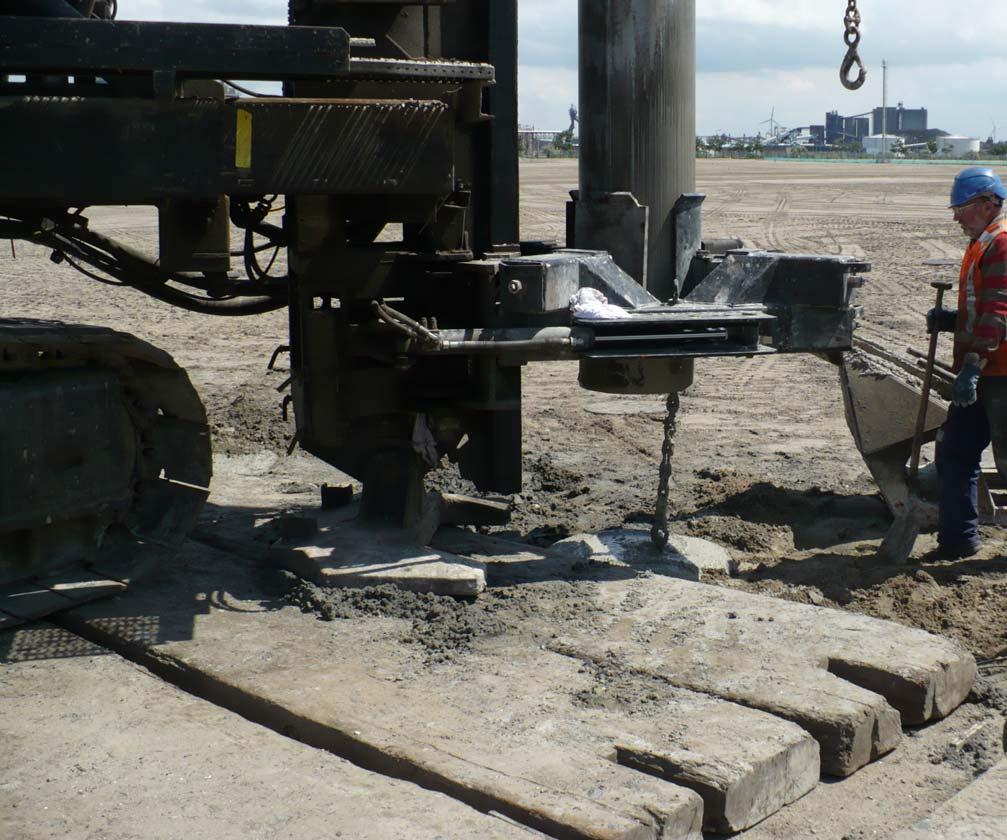
3 SOIL INVESTIGATION AND GEOLOGICAL BACKGROUND For the preliminary soil investigation the standard penetration test (SPT) was used. The number of SPT-soundings executed was 7 and the average depth about 15 meters. The final soil investigation was done by cone penetration tests (CPT). The cone and the shaft resistance were measured electronically. The diameter of the cone was 36 mm and the tip angle 60. CPT-soundings were made in 275 points altogether, 168 points were made in chosen areas during the piling work. The biggest sounding depth was about 30 meters. As a complementary method the SIPT-sounding (Static Impact Penetration Test) was used (Ref.1). The SIPT-sounding is a combination of ram sounding and stress wave measurement. In the SIPT-sounding the diameter of the cone is 45 mm and the tip angle 90. The cone resistance is determined by stress wave measurements. The SIPT-sounding was developed in Finland, and the method is especially suitable for the determination of the soil parameters of frictional soils. The shear and stress waves of the different soil layers were measured by the seismic "Down Hole"-method. These seismic measurements were made in one hole. Soil samples were taken from 20 holes. The soil sampling was extended down to 60 meters. The total amount of soil samples was 56. The ground water level was measured in two holes. The ground level of the planned paper milt varies between 115 and 123 meter above sea level. The soil conditions are the following (see figures 1 & 2): The top soil has a thickness of about 0.5 meters. The top soil is underlain by layers of clayey silt and silty clay (in German called "Geschiebelehm"). This layer contains mainly silt and clay, with thin layers of sand or gravel in between. The depth of this layer varies between 7 and 15 meters. The water content was 12 to 37% The average CPTvalues were about 2 MPa. There below, layers of sand were encountered, reaching down to the depth of 22 to 23 meters (thickness between 8 and 15 meters). The sand layer is medium or dense, and also contains both hard, thin gravel layers with small stones and thin fine layers of sand and silty sand. The CPT-values were between 16 to 70 MPa and the friction angle between 32 to 43. The most dense part of these sand layers is their upper part. Below the sand are layers of clay, with a mainly stiff consistence. The clay also contains layers of sand and silt and even brown coal. These layers reach down the depth of at least 56 meters, as shown by the continuous soil sampling. The cone resistance of the clay layer is about 4 MPa and the water content varies between 15 to 34%. According to general geological information from the area, the clay is underlain by thick layers of sand, reaching down to a depth of -80 to -90 m, where formations of chalk will be encountered. PILESYSTEM. The pilesystem to be choosen of was restricted to a displacement type of pile. Since the environmental aspects were hardly relevant, a driven system was offered by almost all bidders. Although precast, prestressed piles were allowed, the joint venture of Fundex-Terracon decided to offer cast-inplace driven piles such as the Vibrex- and Vibropiles. Vibrex- and Vibropiles are classified as displacement piles, which utilize the driving of a temporary steel casing with a watertight steel shoe (footplate) at the bottom end. The steel casing is subsequently withdrawn and the vold filled with concrete after a reinforcement cage is placed. The driving is performed by either a diesel explosion hammer or a Hydrohammer. Extraction of the casing is done by a special Fundex vibrator which is clamped around the tube (Vibrexpiles), or with the Hydrohammer switched in reverse mode (Vibropiles) (Ref. 2). Since both companies had gained broad experience on various similar projects, inclusive Papermills in The Netherlands (Ref. 3), England, France, Portugal and Finland, a complete proposal based upon this type of pile system was accepted by the client. Other special advantages of this system for such projects are the easy and simple adapting possibilities when all detailed engineering is not completed at the start of the work. With respect to the encountered soil conditions also quick changes on the site are possible. The pile length can be adjusted to the anticipated blowcount, and eventual underground obstructions like hard layers and occasional boulders will not cause insuperable problems. During the progress of the piling works an average production rate was achieved of 20 piles per rig per day, and the record height of various days was over 180 piles by 6 piling rigs. The total number of piles exceeded 8800 (inclusive approx. 500 inclined piles) and were installed within 4 months. 3
4 DESIGN ANALYSES (loads and settlements) The contract specified 3 types of piles: P - 500; maximum working load 500 kn, allowable settlement 8 mm P -1400; maximum working load 1400 kn, allowable settlement 8 mm MP -1400; maximum working load 1400 kn, allowable settlement 6 mm Pile lengths were specified from 8-12 meters. Following pile types were proposed by the contractor: P - 500, shaft Ø 324 mm, footplate Ø 370 mm P , shaft Ø 406 mm, footplate Ø 450 mm MP -1400, shaft Ø 457 mm, footplate Ø 525 mm The calculation of the geotechnical bearing capacity of the piles was based upon the results of the CPT's, using the so called 4D/8D method which has been developed on the results of hundreds of static pile loading tests in the past. The calculation method takes into account the average cone resistance between 4 times the pile diameter (4D) under the pile toe and 8 times the pile diameter (8D) above pile tip elevation. The ultimate shaft resistance can be derived from 1.4% of the average cone resistance in the sand layers. The safetyfactor on both the ultimate end bearing capacity and the ultimate shaft resistance is n = 2. Based upon these calculations, pile tip elevations were designed from 10 to 12 m. The penetration of the piles into the bearing sand layers had to be limited from 1 to 1.5 meter. Deeper penetration would increase the risk of possible punching through the bearing sand layers in most areas of the paper mill. From the results of static pile loading tests it can be derived that at 50% of the ultimate bearing capacity of the pile, so at allowable working or service load (with safety n = 2) a settlement of approximately 1% of the pile-end diameter can be expected. If however a higher safety-factor n' is applied, the settlement will be s=n/n'x1% D, so when using n' = 3, the settlement will be 2/3 x 1% = 0.67% D. In addition to this direct settlement, some elastic deformation of the concrete pile shaft can be expected ranging from 3 to 4 mm. Depending on the actual safety factor n', the specified settlement criteria of the 3 pile types could be achieved. The calculated load settlement behaviour was confirmed by the pile loading tests on single piles. However the deeper clay layers (from 23.0 m to m depth) will cause additional settlement for the paper mill as a whole. In case differential settlements become unacceptable, the sensitive paper machines itself can be adjusted with special jack-up devices that wilt be mounted between foundation and paper machine itself. PILE DRIVING ANALYSES (PDA) The initial PDA-measurements of 23 piles were executed during the test piling in March The purpose of the pile testing was to evaluate the driving conditions, to determine the pile lengths and to obtain verification of the dependency of the end bearing capacity versus blow counts for piles in different areas. The second part of PDA-tests of 13 piles was executed during the piling work in May 1993, in order to obtain more accurate indication of pile lengths and to specify the driving regulations for the various areas. The measurements were done for three different sizes of steel driving tubes and bottom plates. In this case it was only possible to determine the end resistance of the steel bottom plate. The measured results for different pile types are shown in figures 3, 4 and 5. 4
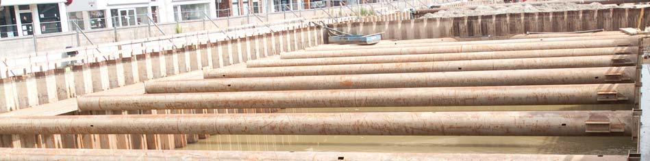
5 STATIC PILE LOADING TESTS The planned scope of pile loading tests. The scope of pile loading tests which was planned in the schedule of pile work was small and in accordance with the scale required in the relevant standards. It was planned to carry out one or two static tests on every type of pile. One pile of each type should be loaded up to the ultimate resistance. First of all, these piles were driven at various locations beside the areas of the buildings. Further tests were planned on working piles with a load up to the service load. In April 1993 the first tests commenced. It was necessary to have a counterweight of at least 2800 kn in order to provide the maximum capacity. In most areas of the building the piles are designed with a very close spacing so that it was not possible to place tie rods in between the piles. Because of that the contractor built up five tanks, put them together with a construction of steel beams and filled them with water, so that they provided the necessary counterweight. Between the beams and the top of pile a hydraulic press was placed, together with the instruments for measuring the vertical and horizontal motions of the pile. As a check on the measurements, two levels were placed at locations 30 m from the pile, at 90 to each other. First results. By the end of April the first results of static loading tests on two test piles and two working piles became available. The load / settlement behaviour of both test piles was satisfactory, white that of the 2 working piles did not reach the requirements. Results of the first tour load tests Pile no. Pile size Design Settlement Max. Load Settlement Pile types (mm) Load (kn) (mm) (kn) (mm) PD / group 310/ / single D22 406/ group 212/ / single Pile D22 was test loaded for a second time a few weeks later. In the first test the ultimate load of the pile appeared to be reached by 1500 kn because in the load-settlement-curve clearly became steeper at this point. This could not be confirmed in the second test. On reaching the maximum applied bad of 2650 kn, the typical form of a load-settlement curve with the point of ultimate load could not be found. The additional settlement was 18.1 mm, bringing the total settlement to 28.8 mm because the permanent settlement of the pile after the first loading test was 10.7 mm. The additional settlement under the design bad of 1400 kn was 5.4 mm bringing the total to 5.4 mm mm = 16.1 mm. The permanent settlement after unloading was 10.2 mm mm = 20.9 mm. What was obvious from the afore mentioned results was the substantial difference between the good load / settlement behaviour of a single, isolated pile compared to the poor behaviour of a similar pile forming part of a group. Soil conditions, pile size and driving characteristics were in principle identical for both pile types and thus the behaviour of all piles ought to be identical as well. The observes load / settlement behaviour of the completed working piles on this site showed nevertheless a much larger variation than normal. This variation was similar to that shown by the static loading tests. The occasionally soft" behaviour of working piles could not be attributed to inadequate soil bearing, neither to the selection of a wrong driving depth, nor to initial pile deficiencies. The observed differences in pile behaviour were characteristic for soil heave that affects initially excellent piles, completed previously. Heave also leads to a "soft" load / settlement behaviour of completed piles in combination with a reduced bearing capacity, when the allowable settlement of the foundation is limited. All piles were sound and showed the required stiff load / settlement behaviour after completion and harding of the concrete. Additional loading tests. After consideration of the facts, and coming to the conclusion that soil heave must be the reason of the observed phenomenon, additional static loading tests and further types of pile testing methods have been designed. The assumption that piles heave during driving adjacent piles could be confirmed by measuring the vertical movement of the completed pile during production of the adjacent piles. The piles moved vertically on average 30 to 80 mm. 5
6 DYNAMIC PILE TESTS Dynamic pile tests were made to obtain results of more tests in a shorter time. Only one static loading test could be done every two days because of the large amount of time for building up the equipment and the long period of testing. It is possible to do one dynamic pile test in two to three hours. For testing the pile special equipment for free fall was used. The falling weight was 7.0 t and the drop height was 1.0 m. The pile which has to be tested is defined as an elastic rod with a spread of waves in one dimension. During testing the transformation of the pile and the speed of compression is measured. The measurements have been analysed in accordance with the CASE-method which gave a first result on site. To obtain a load-settlement-curve the recorded signals of the tested piles have been processed by the CAPWAP-method. It needs a long time to get a result with this method because of the necessary iteration of the measurement results and the model ("Signal matching"). Correlation to static loading tests. Two piles which have been static load tested have also been tested by the dynamic method so that it is now possible to make a comparison of the two results (see figures 6 and 7). Results of the tests with static and dynamic method Pile no. Pile size Design Settlement Max. Load Settlement Test type (mm) Load (kn) (mm) (kn) (mm) 310/ / static (11.0) dynamic 212/ / static (15.0) dynamic The CAPWAP analysis gives the ultimate load as the max. load. The two piles have not been static load tested up to the ultimate load, as could be seen in the load-settlement-curve of these tests. For the maximum load of these tests the settlement has also been calculated by CAPWAP. The results are shown into brackets. The comparison of these results shows that the two methods produce similar results, particularly in the area of service load. PSPLT (Pseudo Static Pile Load Tests) In addition to the previous indicated Loading Tests, pile capacities were checked by the PSPLT. The PSPLT is a method developed by Fundex in cooperation with IFCO (The Netherlands), as a relative economic and quick alternative versus static loading tests. The equipment consists of a heavy weight of 25 tons, mounted on a undercarriage with crawler tracks. This rig is able to drive through rough terrain conditions. The test is carried out by dropping the mass of 25 tons on the pile. In order to soften the impact and increase its duration a composite of heavy coiled springs are fixed to the bottom side of the drop mass. This endures a slow-rising long lasting blow into the pile with a duration which is long-continued compared to the shock-wave travel time to the lower end of the pile and backwards. The dynamic soil effects which are present during a dynamic load test are avoided. The duration of the impact is over 100 ms (50% half width time). The time for the shock-wave to travel up and down a 10 meter concrete pile is about (2'10 m/(4000 m/s)) = 5 ms. The relative long load force on the pile is why this type of test is called "Pseudo Static" (Ref.4). A simplified model (Ref.5) of the weigth-mass m on a spring with a compressibility K against a solid base will show its principle. The maximum force Fmax is: mgh = 0.5(Fmax)2/K The drop height of the weight is identified as h The duration of the impact time is then calculated as t * = (m/k) Within the PSPLT used values are: kg for the mass and a spring compressibility of 8 MN/m. Thus resulting in a total load-time of 200 ms (full width-time). Although the maximum drop-height is about 3.5 meter it is not reflecting the total load time (see figure 8). 6
7 On completion of the stroke the mass bounces back and is caught at its highest position by hydraulic clamps, and therefore a second uncontrolled blow is avoided. The load settlement curve is obtained by direct measurement of force versus displacement. The force is measured with a calibrated dynamic load cell. The displacement of the upper end of the pile is measured continuously with an optical measuring device, monitoring the displacement from a distance over 15 meter away. This distance eliminates the influence of the ground vibrations. The force-time signal and displacement-time signal are registered and stored on a MS-DOS computer which directly plots the result in a load-settlement curve. Additional testing at the same pile with various increased drop heights will obtain supplementary points in the load-settlement curve. Before and after the Loading Test with the PSPLT the integrity of the pile is controlled with a low strain integrity test. This check is a precaution to ensure that no damage will be caused to the pile. Results The PSPLT has measured the load settlement curves of 10 piles in this project. A large difference in load characteristics is observed, what is explained by the difference in behaviour of the single piles and those located within a pile group. This difference is attributed to heave of the piles in a group. The statically tested single piles HO/ and G30/ show after the pile loading test a small permanent settlement while at other test settlements over 50 mm are recorded. The results of both the PSPLT tests and on the same pile performed static loading tests are presented in figure 9.. It is observed that the results from the PSPLT are somewhat more positive" towards the full capacity of the pile. The main cause here is found in the Pact that both piles were "preloaded", because on Pile HO the static Loading test was executed about 2,5 weeks before, and on Pile G30 both a static- and a dynamic loading test. Respectively 5 and 4 days prior to the PSPLT. The "stiffer. behaviour is explained furthermore as a dynamic effect, however the Capacity based upon Static Loading Tests are not defined in a single common accepted standard. Other occurrences as pore pressure, creep, load step/increments and the age of the pile shaft are of influence. It is generally known that the pile set up increases in time. This has been investigated in many circumstances and is also demonstrated when a pile is redriven some time after installation. The initial set up is low due to pore pressure and molding of the soil. HEAVE When a displacement pile is installed, its volume has to be accommodated below the ground surface by vertical and lateral displacements of the soil. Effects of consequential heave or compaction may be unacceptable to adjacent structures. In some soils the vertical displacement or heave resulting from subsequent piling may carry with it piles that have already been driven. This may cause end-bearing piles to be lifted off their bearing stratum (Ref.6). In practice there are very few sites, where heave is encountered in a manner, that the piles are subjected to damage. The phenomenon has got very little attention in the professional literature and most designers and specialist contractors are not familiar with it. At the start of this project no indications were present whatsoever that any heave was to be expected. The soil report also gave no indications to this respect. After installation of the single non working piles and PDA testing the initial results were extremely encouraging. This resulted in a determination of pile tip levels and productional driving was started immediately. Only when the static-loading test on a pile from a pile-group -failed", the phenomenon of heave became recognized. Then the effort was to determine if these heaved piles would reach their capacity, and therefore the PSPLT was mobilized. The scope was quickly defined that the majority of the piles from the pile-groups were to be re-tapped. Since all piles were fully reinforced over their entire pile length, the whole exercise was possible without damage to the pile's ultimate integrity. Further investigations were performed by leveling the upper end of the completed piles to learn what the reaction is of a hardened (cured) pile to the driving of the steel piling tube nearby. The driving was interrupted every 3 m, in order to carry out the leveling of 4 nearby piles. The existing piles were present in a square of 1.50 x 1.50 m2. The tube was driven at 1.50 m distance from pile 4 in line with the piles 3 and 4 and thus 3.00 m from pile 3. Pile 2 was at a distance of ( ) = 3.35 m. 7
8 The results of the leveling were as follows: Distance (m) heave in mm driving depth tube in m age of piles in days The obtain more information on the phenomenon of heave on this particular site a test was carried out on a group of 8 test (non-working) piles Ø 406/450 mm at distances of 1.50 m. On 2 piles the effect of heave was measured both at the upper part of the pile and at the lower part of the pile by leveling. The results are shown in figure 10. Other locations were piles were at close c.t.c. distances and stilt to be driven, pre-boring over the first part of the pile was commenced. These additional works were executed simultaneously with the other progress at the site without significant delay to the overall schedule. SUMMARIZE Soil heave is a consequence of the application of displacement-type of piles, passing through a sufficiently thick stratum with a low permeability. Heave is influenced as follows: I An over-consolidated subsoil increases heave. If the initial horizontal effective stress in the subsoil is larger than usual and especially when this horizontal stress is in excess of the vertical stress, heave will result immediately. II If the surface of the soil has been lowered, the soil will have shown an elastic rebound and that encourages heave as well. III The pile concentration in combination with the resulting soil compaction is to surpass a certain minimum. That minimum is at the present site almost zero, so that here very little soil compaction will already initiate "heave". IV V Heave increases with increasing pile density per unit of area. Heave increases when the interval between the installation of adjacent piles is short, so that the excess pore water pressures, that have been generated by one pile, have not had adequate opportunity to dissipate before the next pile is driven. On the site in Eilenburg all above mentioned conditions were fulfilled, so that the circumstances for the occurrence of soil heave were adverse. Heave can be observed on site as the ground surface around installed piles moves apparently upwards. The amount of heave shows a clear relation with the pile density. CONCLUSION At the Sachsen Paper Mill in Eilenburg over driven cast-in-situ piles have been installed. A number of static and dynamic pile loading tests were performed and compared to check the piles on their load-settlement behaviour. As a result of local soil conditions, heave was encountered during the execution of the piling, which problem was solved by re-driving and pre-drilling. In spite of the difficult circumstances, soil-conditions and tight time schedule, the piling works were brought to successful completion because of close co-operation between the project's management-team Lemcon-Züblin, its consultant Fundus Ltd. and the piling contractor Fundex-Terracon. Due to this close and succesful co-operation, the paper mill of Sachsen Papier Eilenburg is in full operation from September 1994 on, as scheduled. 8
9 REFERENCES 1. L. Aaltonen, 0. Tirkkonen, R. Wikstrom. "A New Design Method of Rammed Piles", Proceedings IV Int. Conference on the Application of Stress-Wave Theory to Piles. The Hague, The Netherlands, 1992 pp S. Doornbos, "Fundex techniques for forming in situ reinforced concrete piles" - Groundengineering, Vol. 19/ No. 2, March S. Doornbos, "The Application of Tubex - groutinjection -piles for the Parenco Paper Mill PM-1 in Renkum, The Netherlands". Proceedings of the DFI 12th annual member's meeting and seminar, Hamilton Canada, October P. Middendorp, "Statisch-Dynamisch Proef belasten" Proceedings Funderingsdag 1993 Apeldoorn (proceedings in Dutch language) 5. F.G. Bell, "Ground Engineers Reference Book" publ. by Butterworths Ltd ISBN H. Gonin, et al "Theory and performance of a new dynamic method of pile testing'. Proceedings II int. Conference Application of Stress-Wave Theory on piles. Figure 1 : Principle section of the soil conditions Figure 2 : Typical CPT-diagram from the area, friction ration/ cone resistance Figure 3 : End bearing capacity of Ø 324 x 20 mm Figure 4 : End bearing capacity of Ø 406 x 25 mm Figure 5 : End bearing capacity of Ø 457 x 25 mm Figure 6 : Dynamic pile test 310/049 Figure 7 : Dynamic pile test 212/080 Figure 8 : PSPLT equipment Figure 9 : PSPLT test results Figure 10: Test results showing heave 9
10 10
11 11
12 12
13 13
14 14
15 15
16 16
17 17
18 18
19 19
20 20
21 21

22 22
23 23
Typical set up for Plate Load test assembly
 Major disadvantages of field tests are Laborious Time consuming Heavy equipment to be carried to field Short duration behavior Plate Load Test Sand Bags Platform for loading Dial Gauge Testing Plate Foundation
Pile foundations Introduction
 Engineering manual No. 12 Updated: 06/2018 Pile foundations Introduction Program: Pile, Pile CPT, Pile Group The objective of this engineering manual is to explain the practical use of programs for the
The Technical and Contractual Matters of Bored Piling Works. By Wallace Yeung Vibro (H.K.) Ltd.
 Ltd.") The Technical and Contractual Matters of Bored Piling Works By Wallace Yeung Vibro (H.K.) Ltd. What is large diameter bored pile? How to construct a large diameter bored pile? Its advantages and limitation
The Technical and Contractual Matters of Bored Piling Works By Wallace Yeung Vibro (H.K.) Ltd. What is large diameter bored pile? How to construct a large diameter bored pile? Its advantages and limitation
Offshore pile acceptance using dynamic pile monitoring
 Offshore pile acceptance using dynamic pile monitoring Webster, S. & Givet, R. GRL Engineers, Inc. Charlotte, NC, USA Griffith, A. Saudi Aramco, Dhahran, Saudi Arabia ABSTRACT: Dynamic pile monitoring
Performance of high capacity jack-in pile for high-rise building with preboring in weathered sedimentary rock formation
 Performance of high capacity jack-in pile for high-rise building with preboring in weathered sedimentary rock formation Chee-Meng, Chow i), Jason A.H. Lim ii) and Yean-Chin, Tan iii) i) Director, G&P Geotechnics
3.1 Scope of the work-capacity Estimation of Drilled Shaft Bearing on Rock
 Chapter 3-Methodology 3.1 Scope of the work-capacity Estimation of Drilled Shaft Bearing on Rock The research work involved the use of high strain dynamic stress wave measurements for capacity estimation
SECTION / ENGINEERED AGGREGATE PIERS (SOIL REINFORCEMENT AND FOUNDATION SYSTEM)
") PART 1 GENERAL 1.01 WORK INCLUDED SECTION 02360 / 31 34 30.13 ENGINEERED AGGREGATE PIERS (SOIL REINFORCEMENT AND FOUNDATION SYSTEM) A. Provide all equipment, material, labor and supervision to design and
PART 1 GENERAL 1.01 WORK INCLUDED SECTION 02360 / 31 34 30.13 ENGINEERED AGGREGATE PIERS (SOIL REINFORCEMENT AND FOUNDATION SYSTEM) A. Provide all equipment, material, labor and supervision to design and
Combined Pile Foundation System for a Residential Complex
 Combined Pile Foundation System for a Residential Complex Alvin K.M. Lam, Geotechnical Engineer, Ove Arup & Partners Hong Kong Limited, Hong Kong, China; email: alvin.lam@arup.com Daman D.M. Lee, Civil
Conference: IFCEE International Foundations Congress and Equipment Exposition
 Conference: IFCEE2018 - International Foundations Congress and Equipment Exposition Paper Title: Bonner Bridge Replacement Project - Pile Driving Experience Authors: Scott Webster 1, Karen Webster 2 1
JACK-IN PILE IN MALAYSIA: A MALAYSIAN CONSULTANT S PERSPECTIVE
 Proceedings of the VLA Seminar, 18 March 211 JACK-IN PILE IN MALAYSIA: A MALAYSIAN CONSULTANT S PERSPECTIVE Tan, Yean-Chin, Chow, Chee-Meng & Gue, See-Sew G&P Geotechnics, Malaysia (www.gnpgroup.com.my)
High strain dynamic testing in micropiles. Comparison of static and dynamic test results
 High strain dynamic testing in micropiles. Comparison of static and dynamic test results Oteo, C. Dpto. Ingeniería del Terreno, A Coruña University, A Coruña, Spain Arcos, J.L. & Gil, R. Kronsa Internacional,
USE OF DIPP PILES FOR A NEW SUP BRIDGE IN WEST MELBOURNE
 USE OF DIPP PILES FOR A NEW SUP BRIDGE IN WEST MELBOURNE If you want to put a photo on the title slide use this layout with colour photos (delete this box) Michael Wei, Jawad Zeerak & David Barton 8 th
Application of Vibro Techniques for Infrastructure Projects in India
 Application of Vibro Techniques for Infrastructure Projects in India Rainer Wegner Contract Manager, Keller Grundbau GmbH, Germany Dr. V.R. Raju Director, Keller Ground Engineering India Pvt Ltd, India
Overburden Effect on the Axial Resistance of Instrumented CFA Piles. Knoxville, TN 37922, ph ,
 703 Overburden Effect on the Axial Resistance of Instrumented CFA Piles Timothy C. Siegel 1, M. ASCE, P.E., G.E., D.GE and Peter Faust 2 1 Principal Engineer, Dan Brown and Associates, PC, 1808 Northshore
Comparison of the results of load test done on stone columns and rammed aggregate piers using numerical modeling
 Comparison of the results of load test done on stone columns and rammed aggregate piers using numerical modeling Ece Kurt Civil Eng., M.Sc.& Geoph. Eng., Istanbul, Turkey Berrak Teymur Asst. Prof. Dr.,
A.Zh.Zhussupbekov Department of Civil Engineering and Engineering Mechanics, Columbia University, New York, USA
 UDK 69.0 A.Zh.Zhussupbekov Department of Civil Engineering and Engineering Mechanics, Columbia University, New York, USA Research of displacement pile and continuous flight auger technologies on construction
Design and Construction of Drilled Full Displacement Piles using the Penetration Resistance Method
 SUPERPILE 2009 Burlingame, CA Design and Construction of Drilled Full Displacement Piles using the Penetration Resistance Method Peter Faust Malcolm Drilling Company Inc. Alexandria Parking Garage, San
PILE CAPACITY REDUCTION OF JACK-IN PILES WITH EMPTY PREBORED HOLE AT META-SEDIMENTARY FORMATION IN PENINSULAR MALAYSIA
 PILE CAPACITY REDUCTION OF JACK-IN PILES WITH EMPTY PREBORED HOLE AT META-SEDIMENTARY FORMATION IN PENINSULAR MALAYSIA Liew Shaw Shong, Ho Shu Feng and Voon Boo Chuan G&P Geotechnics Sdn Bhd, Wisma G&P,
Ching Guan Kee ABSTRACT
 Japanese Geotechnical Society Special Publication The 15th Asian Regional Conference on Soil Mechanics and Geotechnical Engineering Effects of base grouting and deep cement mixing on deep foundation bored
Lantz-Boggio Architects, P.C LBA Project No
 SECTION 313430- PART 1 GENERAL 1.1 WORK INCLUDED A. Provide all equipment, material, labor and supervision to design and install Engineered Aggregate Piers for the soil reinforcement. Design shall rely
Subsoil Bearing Capacity from Load Test Results In Two Locations in Rivers State, Nigeria
 IOSR Journal of Applied Geology and Geophysics (IOSR-JAGG) e-issn: 2321 0990, p-issn: 2321 0982.Volume 4, Issue 4 Ver. II (Jul. - Aug. 2016), PP 27-35 www.iosrjournals.org Subsoil Bearing Capacity from
Exploration, Sampling, and In Situ Soil Measurements. Dr. Omar Al-Hattamleh
 Exploration, Sampling, and In Situ Soil Measurements Dr. Omar Al-Hattamleh Purpose of Soil Exploration Information to determine the type of foundation required (shallow or deep). Information to allow the
Performance of Mechanically Stabilized Earth walls over compressible soils
 Performance of Mechanically Stabilized Earth walls over compressible soils R.A. Bloomfield, A.F. Soliman and A. Abraham The Reinforced Earth Company, Vienna, Virginia, USA ABSTRACT: Two projects have recently
THE ADVANTAGES OF THE USE OF GPS BASED LOGGING SYSTEMS FOR VERTICAL DRAIN INSTALLATION PROJECTS
 International Conference on Soft Ground Engineering (ICSGE2015) 3-4 December 2015, Singapore THE ADVANTAGES OF THE USE OF GPS BASED LOGGING SYSTEMS FOR VERTICAL DRAIN INSTALLATION PROJECTS JEROEN DIJKSTRA
Section Steel H-Piling Tender No. [ ] Page 1
![Section Steel H-Piling Tender No. [ ] Page 1](/thumbs/79/79905259.jpg "Section Steel H-Piling Tender No. [ ] Page 1") Tender No. [ ] Page 1 1.0 GENREAL 1.1 DEFINITIONS.1 Refusal is attained when the resistance to pile penetration for the last 150 mm of driving is not less than [ blows/mm] with a final set of [ blows]
Tender No. [ ] Page 1 1.0 GENREAL 1.1 DEFINITIONS.1 Refusal is attained when the resistance to pile penetration for the last 150 mm of driving is not less than [ blows/mm] with a final set of [ blows]
Earth Mechanics, Inc. Geotechnical & Earthquake Engineering
 DATE: August 31, 2000 Earth Mechanics, Inc. Geotechnical & Earthquake Engineering TECHNICAL MEMORANDUM EMI PROJECT NO: 99-136 PREPARED FOR: COPIES: PREPARED BY: Tayfun Saglam / Parsons Brinckerhoff Juan
STATIC AND HIGH STRAIN DYNAMIC TEST CO-RELATION STUDIES ON CAST-IN-SITU CONCRETE BORED PILES
 STATIC AND HIGH STRAIN DYNAMIC TEST CO-RELATION STUDIES ON CAST-IN-SITU CONCRETE BORED PILES Dr. N.V. Nayak, Director, Gammon India Limited, India D.K. Kanhere, Chief Engineer, Maharashtra State Road Develop.
INTERPRETATIONS OF INSTRUMENTED BORED PILES IN KENNY HILL FORMATION
 INTERPRETATIONS OF INSTRUMENTED BORED PILES IN KENNY HILL FORMATION S. S. Liew 1, Y. W. Kowng 2 & S. J. Gan 3 ABSTRACT This paper presents the results of two instrumented bored cast-in-situ test piles
UNIFIED FACILITIES GUIDE SPECIFICATIONS
 USACE / NAVFAC / AFCEC / NASA UFGS-31 62 13.26 (April 2006) ----------------------------- Preparing Activity: NAVFAC Replacing without change UFGS-02466 (August 2004) UNIFIED FACILITIES GUIDE SPECIFICATIONS
Construction Planning, Equipment, and Methods PILES AND PILE-DRIVING EQUIPMENT
 CHAPTER Construction Planning, Equipment, and Methods PILES AND PILE-DRIVING EQUIPMENT Sixth Edition A. J. Clark School of Engineering Department of Civil and Environmental Engineering 19 By Dr. Ibrahim
A Case Study: Foundation Design in Liquefiable Site
 RESEARCH ARTICLE OPEN ACCESS A Case Study: Foundation Design in Liquefiable Site Tahar Ayadat* *(Department of Civil Engineering, College of Engineering, PMU University, P.O. Box 1664, Al-Khobar, 31952,
Foundation Innovations Ensure Successful Bridge Replacement
 COVER STORY Foundation Innovations Ensure Successful Bridge Replacement Rhode Island s new $163.7 million, 2,265 ft (690 m) long, fourlane Sakonnet River Bridge sits just south of the existing bridge in
June i TABLE OF CONTENTS
 June 2005 - i - 05-526 TABLE OF CONTENTS SECTION PAGE 1.0 INTRODUCTION... 1 1.1 Purpose of the Investigation... 1 1.2 Description of the Project and Scope of Work... 1 1.3 Site Geology... 1 1.4 Site Description
Steel screw settlement reduction piles for a raft foundation on soft soil
 Proc. 18 th NZGS Geotechnical Symposium on Soil-Structure Interaction. Ed. CY Chin, Auckland Alexei Murashev Opus International Consultants Limited, Wellington, New Zealand. Keywords: piled raft, settlement
Post-Grouting of Drilled Shaft Tips on the Sutong Bridge: A Case History
 Post-Grouting of Drilled Shaft Tips on the Sutong Bridge: A Case History Dr. Osama Safaqah 1, P.E., Robert Bittner 2, P.E. & Xigang Zhang 3 1 Project Manager, Ben C. Gerwick, Inc., 20 California Street,
Bi-Directional Static Load Testing of Driven Piles
 Bi-Directional Static Load Testing of Driven Piles Paul J. Bullock, PhD Fugro Consultants Inc. Loadtest Bi-Directional Osterberg Cell Testing Specialized jack in pile uses bearing to mobilize side shear
Large-scale dynamic high-strain load testing of a bridge pier foundations
 Large-scale dynamic high-strain load testing of a bridge pier foundations Hussein, M. GRL Engineers, Inc., Orlando, Florida, USA Bullock, P., & Rausche, F. GRL Engineers, Inc., Cleveland, Ohio, USA McGillivray,
Evaluation of negative skin friction on sheet pile walls at the Rio Grande dry dock, Brazil
 Geotechnical Aspects of Underground Construction in Soft Ground Viggiani (ed) 2012 Taylor & Francis Group, London, ISBN 978-0-415-68367-8 Evaluation of negative skin friction on sheet pile walls at the
Deep Foundation Testing, Analysis and Consulting Services
 Deep Foundation Testing, Analysis and Consulting Services PDA Testing and Monitoring Dynamic Load Testing- APPLE Thermal Integrity Testing Crosshole Sonic Logging SPT Energy Calibration Low Strain Integrity
Study of Various Techniques for Improving Weak and Compressible Clay Soil under a High Earth Embankment
 MATEC Web of Conferences 11, 03006 ( 2014) DOI: 10.1051/ matecconf/ 20141103006 C Owned by the authors, published by EDP Sciences, 2014 Study of Various Techniques for Improving Weak and Compressible Clay
SEMINAR. Introduction to Continuous Flight Auger (CFA) piling Thursday 21/8/2013. Facilitator: Martin Larisch
 piling Thursday 21/8/2013. Facilitator: Martin Larisch") SEMINAR Introduction to Continuous Flight Auger (CFA) piling Thursday 21/8/2013 Facilitator: Martin Larisch 1 Brief History of Piling Contractors, its capabilities and market Introduction to CFA piling
SEMINAR Introduction to Continuous Flight Auger (CFA) piling Thursday 21/8/2013 Facilitator: Martin Larisch 1 Brief History of Piling Contractors, its capabilities and market Introduction to CFA piling
Evaluation the Effectiveness of Rapid Impact Compaction (RIC) as a Ground Improvement Technique
 as a Ground Improvement Technique") Evaluation the Effectiveness of Rapid Impact Compaction (RIC) as a Ground Improvement Technique Bashar Tarawneh, Ph.D, P.E Assistant Professor Civil Engineering Department The University of Jordan Amman,
Evaluation the Effectiveness of Rapid Impact Compaction (RIC) as a Ground Improvement Technique Bashar Tarawneh, Ph.D, P.E Assistant Professor Civil Engineering Department The University of Jordan Amman,
Importance of tailings properties for closure
 Proceedings of Mine Closure Solutions, 2014 April 26 30, 2014, Ouro Preto, Minas Gerais, Brazil Published by InfoMine, 2014 InfoMine, ISBN: 978-0-9917905-4-8 Importance of tailings properties for closure
Misan University - College of Engineering Civil Engineering Department
 CHAPTER 2 Soil and Excavations Soil investigation including two phases: surface investigation and subsurface investigation Surface investigation involves making a preliminary judgment about the site s
Implementation of this Special Provision requires a complete understanding of the following documents:
 VIRGINIA DEPARTMENT OF TRANSPORTATION SPECIAL PROVISION FOR Quality Assurance/Quality Control (QA/QC) for the Construction of Deep Foundation Systems for Design-Build and PPTA Contracts November 10, 2009
DHANALAKSHMI COLLEGE OF ENGINEERING, CHENNAI DEPARTMENT OF CIVIL ENGINEERING 2 MARK QUESTIONS WITH ANSWERS CE FOUNDATION ENGINEERING UNIT 1
 DHANALAKSHMI COLLEGE OF ENGINEERING, CHENNAI DEPARTMENT OF CIVIL ENGINEERING 2 MARK QUESTIONS WITH ANSWERS CE6502 - FOUNDATION ENGINEERING Subject Code: CE6502 UNIT 1 1. What are the informations obtained
Earth Mechanics, Inc. Geotechnical & Earthquake Engineering
 Earth Mechanics, Inc. Geotechnical & Earthquake Engineering TECHNICAL MEMORANDUM DATE: June 3, 2009 EMI PROJECT NO: 01-143 TO: COPY: FROM: SUBJECT: John Chun, P.E. / Port of Long Beach (POLB) Jorge Castillo
Skirted Spudcan Sheet Pile Wall Interaction during Jack- Up Rig Installation and Removal in a Harbour Area
 Skirted Spudcan Sheet Pile Wall Interaction during Jack- Up Rig Installation and Removal in a Harbour Area L. Kellezi GEO - Danish Geotechnical Institute 1 Maglebjergvej, DK 2800 Copenhagen, Denmark G.
Bi-Directional Static Load Testing of Drilled Shafts
 Supplemental Technical Specification for Bi-Directional Static Load Testing of Drilled Shafts SCDOT Designation: SC-M-712 (9/15) September 2, 2015 1.0 GENERAL This work shall consist of furnishing all
Bi-Directional Static Load Testing of Drilled Shafts
 Supplemental Technical Specification for Bi-Directional Static Load Testing of Drilled Shafts SCDOT Designation: SC-M-712 (01/18) 1.0 GENERAL This work shall consist of furnishing all materials, equipment,
Axially Loaded Behavior of Driven PC Piles
 Axially Loaded Behavior of Driven PC Piles Shih-Tsung Hsu Associate Professor, Department of Construction Engineering, Chaoyang University of Technology, E-mail address: sthsu@cyut.edu.tw Abstract. To
DIAPHRAGM WALLS, CUT-OFF WALLS AND SLURRY WALLS
 DIAPHRAGM WALLS, CUT-OFF WALLS AND SLURRY WALLS Implenia Spezialtiefbau GmbH Robert Bosch Straße 25 D-63225 Langen Phone: +49 6103 988 345 Fax: +49 6103 988 277 Email: info.spezialtiefbau@implenia.com
UNDERPINNING A CRANE FOUNDATION
 UNDERPINNING A CRANE FOUNDATION Donald R. McMahon, P.E., McMahon & Mann Consulting Engineers, P.C., Buffalo, New York, USA Andrew J. Nichols, P.E., McMahon & Mann Consulting Engineers, P.C., Buffalo, New
Sabah Shawkat Cabinet of Structural Engineering 2017
 3.9 Concrete Foundations A foundation is a integral part of the structure which transfer the load of the superstructure to the soil without excessive settlement. A foundation is that member which provides
On-site determination of pile capacity Distribution of pile load between the shaft and tip, and Detection of possible pile.
 Pile Load Test Pile foundation can be constructed depending on the stiffness of subsurface soil and ground water conditions and using a variety of construction techniques. The most common techniques are
Seismic Design of a Railway Viaduct in a High Seismic Zone
 Seismic Design of a Railway Viaduct in a High Seismic Zone 9 th Small Bridges Conference, Australia 2019 Seismic Design of a Railway Viaduct in a High Seismic Zone 1. Project Overview 2. Typical Project
OFFICE OF STATE AID ROAD CONSTRUCTION MISSISSIPPI DEPARTMENT OF TRANSPORTATION
 Supplemental Specification 901-S-803-1 LFRD Driven Pile Specifications. DATE: May 24, 2010 OFFICE OF STATE AID ROAD CONSTRUCTION MISSISSIPPI DEPARTMENT OF TRANSPORTATION SUBJECT: LRFD Driven Pile Specifications
ADDENDUM NO. 1. PROJECT NAME: Bostic Pelt Road NRCS Drainage Improvements PRI PROJECT NO: Wakulla Co ITB#
 ADDENDUM NO. 1 DATE: January 22, 214 TO: Prospective Bidders via individual e-mails FROM: Alan Wise, P.E. PROJECT NAME: Bostic Pelt Road NRCS Drainage Improvements PRI PROJECT NO: 23.15 ---- Wakulla Co
SEISMIC SOIL-PILE GROUP INTERACTION ANALYSIS OF A BATTERED PILE GROUP
 4 th International Conference on Earthquake Geotechnical Engineering June 25-28, 27 Paper No. 1733 SEISMIC SOIL-PILE GROUP INTERACTION ANALYSIS OF A BATTERED PILE GROUP Nan DENG 1, Richard KULESZA 2 and
Soil Improvement by Compaction Grouting
 CITY AND COUNTY OF DENVER ENGINEERING DIVISION Wastewater Capital Projects Management Standard Construction Specification 31-3223.12 Soil Improvement by Compaction Grouting Part 1 - General 1.01 Introduction
twenty four foundations and retaining walls Foundation Structural vs. Foundation Design Structural vs. Foundation Design
 ALIED ARCHITECTURAL STRUCTURES: STRUCTURAL ANALYSIS AND SYSTEMS DR. ANNE NICHOLS SRING 2018 lecture twenty four Foundation the engineered interface between the earth and the structure it supports that
BORED MICROPILES. I.S.M 2009 London (10 th to 13 th may) 9 th International worksop on micropiles - by A. Jaubertou -
 9 th International worksop on micropiles - by A. Jaubertou -") BORED MICROPILES FRENCH PRACTICE MICROPILES Definition Construction principles (type of micropile) Grouting effect Capacity ( structural and geotechnical ) Load test Connection considerations Mauritius
BORED MICROPILES FRENCH PRACTICE MICROPILES Definition Construction principles (type of micropile) Grouting effect Capacity ( structural and geotechnical ) Load test Connection considerations Mauritius
RIGID INCLUSIONS FOR SOIL IMPROVEMENT IN A 76 BUILDING COMPLEX
 RIGID INCLUSIONS FOR SOIL IMPROVEMENT IN A 76 BUILDING COMPLEX Walter I. Paniagua, PILOTEC, Mexico City Enrique Ibarra, ingeum, Mexico City Jose A. Valle, PILOTEC, Mexico City Abstract: A 76 building complex
SECTION XXXXX AGGREGATE PIERS PART 1 - GENERAL
 SECTION XXXXX AGGREGATE PIERS PART 1 - GENERAL 1.1 RELATED DOCUMENTS: Drawings and general provisions of the Contract, including General and Supplementary Conditions and other Division 00 and Division
LOAD CAPACITY OF AUGER DISPLACEMENT PILES
 International Conference on Ground Improvement and Ground Control (ICGI 2012), 30 Oct. 2 Nov. 2012, University of Wollongong, Australia B. Indraratna, C. Rujikiatkamjorn and J S Vinod (editors) LOAD CAPACITY
Example of the Unified Design procedure for use in the September 8, 2014, short course on in Brazil
 Introduction Example of the Unified Design procedure for use in the September 8, 2014, short course on in Brazil The Unified Design procedure involves two main steps. The first is verifying that the loads
BRE Seminar Ground treatment - Getting the best from difficult sites A Reality Check What Does the Designer Need to Know?
 BRE Seminar Ground treatment - Getting the best from difficult sites A Reality Check What Does the Designer Need to Know? Chris Raison BEng MSc CEng MICE MASCE Raison Foster Associates Introduction A few
Pile Driving Issues. Mark McClelland, P.E. Geotechnical Branch Manager Texas DOT
 Pile Driving Issues Mark McClelland, P.E. Geotechnical Branch Manager Texas DOT Goldilocks?? This soil it too hard This soil is too soft This soil is just right! This soil is too hard Prestressed concrete
Table 1. Typical Soil Parameters Description Bulk Density, kn/m 3 Liquid Limit, % Plastic limit, % Natural Moisture Content, % Cohesion, kn/m 2 Compre
 CASE STUDY CONSTRUCTION OF HIGH ROAD EMBANKMENT OVER THICK SOFT SILTY CLAY- A CASE STUDY Radhakrishnan R, Geo-Enviro Engineers P Ltd, Chennai, Tamil Nadu, India, 044-24483522, geoenviro2012@gmail.com.
CONTINUOUS FLIGHT AUGER (CFA) PILES QC/QA PROCEDURES. Preferred QC/QA Procedures
 PILES QC/QA PROCEDURES. Preferred QC/QA Procedures") Preferred QC/QA Procedures The Federal Highway Administration (FHWA) has provided QC/QA guidance for this technology as noted below. The reference document also contains information about construction
Preferred QC/QA Procedures The Federal Highway Administration (FHWA) has provided QC/QA guidance for this technology as noted below. The reference document also contains information about construction
Grouting Bilfinger Spezialtiefbau GmbH
 Grouting Bilfinger Spezialtiefbau GmbH Goldsteinstrasse 114 D-60528 Frankfurt Phone: +49 69 6688-345 Fax: +49 69 6688-277 Email: info.spezialtiefbau@bilfinger.com www.foundation-engineering.bilfinger.com
BEARING CAPACITY IMPROVEMENT USING MICROPILES A CASE STUDY
 BEARING CAPACITY IMPROVEMENT USING MICROPILES A CASE STUDY G.L. Sivakumar Babu 1, B. R.Srinivasa Murthy 2, D.S. N. Murthy 3, M.S. Nataraj 4 ABSTRACT Micropiles have been used effectively in many applications
Silent Vibrationless. Technology. teel Sheet Piles. Vinyl Piling. etaining Walls. Piles. tory Piling. oundations. ite Piles. n Free Piling.
 s Silent Vibrationless Pile Pressing Technology nchors n Free Piling ilter Weep Holes teel Sheet Piles etaining Walls Vinyl Piling Corner Piles Cofferdams t Basements oundations tory Piling eet Piling
Innovation in Instrumented Test Piles in Malaysia: Application of Global Strain Extensometer (GloStrExt) Method for Bored Piles
 Method for Bored Piles") Innovation in Instrumented Test Piles in Malaysia: Application of Global Strain Extensometer (GloStrExt) Method for Bored Piles... By: Dr H.M. Abdul Aziz bin K.M Hanifah 1 and Lee Sieng Kai 2 (GIEM) 1
Innovation in Instrumented Test Piles in Malaysia: Application of Global Strain Extensometer (GloStrExt) Method for Bored Piles... By: Dr H.M. Abdul Aziz bin K.M Hanifah 1 and Lee Sieng Kai 2 (GIEM) 1
Geotechnical Investigation Reports and Foundation Recommendations -Present status in India -Examples
 Geotechnical Investigation Reports and Foundation Recommendations -Present status in India -Examples Prof. V.S.Raju (Formerly: Director, IIT Delhi & Professor and Dean, IIT Madras) Email: rajuvs_b@yahoo.com
SUPPLEMENTAL TECHNICAL SPECIFICATION
 July 14, 2015 HIGH STRAIN DYNAMIC LOAD TESTING OF DRILLED SHAFTS 1.0 GENERAL This work shall consist of performing high-strain dynamic testing using a drop weight loading system on a test drilled shaft
SCOPE OF WORK FOR PILING JOB
 SCOPE OF WORK FOR PILING JOB 1.0 PURPOSE This document defines the scope of works and specific requirements for the tank pad construction including pile foundation system for the proposed tanks at Wadala
Site Investigation MUHAMMAD AZRIL HEZMI
 Site Investigation MUHAMMAD AZRIL HEZMI Definition Essential part of the preliminary design workon any important structure in order to provide adequateand reliable geotechnical informationand site condition,
SITE INVESTIGATION Validation and Interpretation of data
 SITE INVESTIGATION Validation and Interpretation of data Dr. G.Venkatappa Rao The Impact 1 The Need To determine the type of foundation To assess bearing capacity/settlement Location of Ground water table,issues
GeoEng2000 An International Conference on Geotechnical & Geological Engineering
 GeoEng2000 An International Conference on Geotechnical & Geological Engineering 19-24 November 2000 Melbourne Exhibition and Convention Centre Melbourne, Australia Barrettes : A versatile foundation for
STATNAMIC LOAD TESTING OF HIGH CAPACITY MARINE FOUNDATIONS
 STATNAMIC LOAD TESTING OF HIGH CAPACITY MARINE FOUNDATIONS Mike Muchard, P.E., Applied Foundation Testing, Inc., Tampa, FL, USA STATNAMIC load testing augmented with embedded instrumentation has been successfully
JACK-IN PILE DESIGN MALAYSIAN EXPERIENCE AND DESIGN APPROACH TO EC7
 JACK-IN PILE DESIGN MALAYSIAN EXPERIENCE AND DESIGN APPROACH TO EC7 Chow Chee-Meng & Tan Yean-Chin G&P Geotechnics Sdn Bhd ABSTRACT: Jack-in pile foundation has been successfully adopted in Malaysia since
NEW PERFORMANCE CRITERIA FOR FRESH TREMIE CONCRETE
 NEW PERFORMANCE CRITERIA FOR FRESH TREMIE CONCRETE Karsten Beckhaus (1), Martin Larisch (2), Habib Alehossein (3,4) (1) BAUER Spezialtiefbau GmbH, Deutschland (2) Keller Australia Pty Ltd, Australia (3)
Some observations on Statnamic pile testing
 Proceedings of the Institution of Civil Engineers Geotechnical Engineering 159 October Issue GE Pages 9 73 Paper 111 Received 31/1/5 Accepted 5/1/5 Keywords: field testing & monitoring/ geotechnical engineering/piles
Ground Improvement Piling Piled Retaining Walls Enlarged Head Piles Innovations.
 Ground Improvement Piling Piled Retaining Walls Enlarged Head Piles Innovations www.keller-foundations.co.uk 4 Ground Improvement Solutions Introduction Ground Improvement Solutions Keller Ground Engineering
GROUND IMPROVEMENT USING DYNAMIC REPLACEMENT FOR NCIG CET3 COAL STOCKYARD
 FOR NCIG CET3 COAL STOCKYARD Charles CH Chua 1, Ming Lai 2, Graeme Hoffmann 2 and Brett Hawkins 1 1 Connell Hatch, Australia, 2 Keller Ground Engineering Pty Ltd ABSTRACT This paper presents an overview
GEOTECHNICAL INVESTIGATION PROPOSED OUTFALL LOCATION CITY OF MORGAN S POINT DRAINAGE HARRIS COUNTY, TEXAS REPORT NO
 GEOTECHNICAL INVESTIGATION PROPOSED OUTFALL LOCATION CITY OF MORGAN S POINT DRAINAGE HARRIS COUNTY, TEXAS REPORT NO. 1140198001 Reported to: SIRRUS ENGINEERS, INC. Houston, Texas Submitted by: GEOTEST
Jet Grouting to Increase Lateral Resistance of Pile Group in Soft Clay
 GROUND MODIFICATION, PROBLEM SOILS, AND GEO-SUPPORT 265 Jet Grouting to Increase Lateral Resistance of Pile Group in Soft Clay Kyle M. Rollins 1, Matthew E. Adsero 2, and Dan A. Brown 3 1 Prof. Civil &
SEISMIC DESIGN OF STRUCTURE
 SEISMIC DESIGN OF STRUCTURE PART I TERMINOLOGY EXPLANATION Chapter 1 Earthquake Faults Epicenter Focal Depth Focus Focal Distance Epicenter Distance Tectonic Earthquake Volcanic Earthquake Collapse Earthquake
Dynamic Pile Load Testing. James A. Baigés, PE September 3, 2015
 Dynamic Pile Load Testing James A. Baigés, PE September 3, 2015 Pile Design Outline Ø Project Scope Ø Subsoil Exploration Program- Ø Site Geology, Aerial Photo interpretation stereo pairs Ø Ø Ø SPT, CPT,
CYCLIC PRELOADING OF PILES TO MINIMIZE (DIFFERENTIAL) SETTLEMENTS OF HIGH-RISE BUILDINGS
 SETTLEMENTS OF HIGH-RISE BUILDINGS") 2005/3 PAGES 1 12 RECEIVED 14. 2. 2005 ACCEPTED 18. 4. 2005 H. BRANDL CYCLIC PRELOADING OF PILES TO MINIMIZE (DIFFERENTIAL) SETTLEMENTS OF HIGH-RISE BUILDINGS Heinz BRANDL o.univ.prof. Dipl.-Ing. Dr.techn.
2005/3 PAGES 1 12 RECEIVED 14. 2. 2005 ACCEPTED 18. 4. 2005 H. BRANDL CYCLIC PRELOADING OF PILES TO MINIMIZE (DIFFERENTIAL) SETTLEMENTS OF HIGH-RISE BUILDINGS Heinz BRANDL o.univ.prof. Dipl.-Ing. Dr.techn.
Atlaspile. Full soil displacement bored pile, vibration free - low noise economical
 Atlaspile Full soil displacement bored pile, vibration free - low noise economical Atlaspile Possible applications The Atlaspile is used where more economical driven piles are not practicable for environmental
Rapid Axial Load Testing of Drilled Shafts
 Supplemental Technical Specification for Rapid Axial Load Testing of Drilled Shafts SCDOT Designation: SC-M-712 (9/15) September 4, 2015 1.0 GENERAL This work shall consist of performing a rapid axial
Soil Compaction. Chapter (6) Instructor : Dr. Jehad Hamad
 Instructor : Dr. Jehad Hamad") Soil Compaction Chapter (6) Instructor : Dr. Jehad Hamad 1 2017-2016 What is Compaction? In most instances in civil engineering and/or construction practice, whenever soils are imported or excavated and
Soil Compaction Chapter (6) Instructor : Dr. Jehad Hamad 1 2017-2016 What is Compaction? In most instances in civil engineering and/or construction practice, whenever soils are imported or excavated and
SAMPLE SPECIFICATION for HIGH STRAIN DYNAMIC TESTING of DRIVEN PILES
 SAMPLE SPECIFICATION for HIGH STRAIN DYNAMIC TESTING of DRIVEN PILES October 2014 In using this sample specification, it should be recognized that each site and structure is unique. Therefore, geotechnical
Experimental study on axial and lateral bearing capacities of nonwelded composite piles based on pile load test results
 NGM 2016 Reykjavik Proceedings of the 17 th Nordic Geotechnical Meeting Challenges in Nordic Geotechnic 25 th 28 th of May Experimental study on axial and lateral bearing capacities of nonwelded composite
Better ZSOIL, Better Geotechnical Analysis
 SYMPOSIUM : NUMERICS IN GEOTECHNICS & STRUCTURES 26 YEARS ZSOIL.PC DATE :1-2.09.2011 Better ZSOIL, Better Geotechnical Analysis Practice of Pile Foundation Treatment Based on ZSOIL.PC YIN JI 1,2 Email:sh_geofem@hotmail.com
Tagus Crossing at Carregado (Portugal): A project respectful of its sensitive environment
: A project respectful of its sensitive environment") Tailor Made Concrete Structures Walraven & Stoelhorst (eds) 2008 Taylor & Francis Group, London, ISBN 978-0-415-47535-8 Tagus Crossing at Carregado (Portugal): A project respectful of its sensitive environment
Tailor Made Concrete Structures Walraven & Stoelhorst (eds) 2008 Taylor & Francis Group, London, ISBN 978-0-415-47535-8 Tagus Crossing at Carregado (Portugal): A project respectful of its sensitive environment
Hamburg, GERMANY. Predöhlkai extension project Berth 1
 Hamburg, GERMANY Predöhlkai extension project Berth 1 As one of the world s most important ports, Hamburg will handle an expected 14 million TEU by 2010. This represents a major rise from today s 8.5 million