CHAPTER 5 PILE DRIVING
|
|
|
- Clara Jacobs
- 6 years ago
- Views:
Transcription
1 SDDOT Standard Specifications Section 510 CHAPTER 5 PILE DRIVING
2 PILE DRIVING CHECKLIST U:\op\inspection list Structures Manual, Chapter 5 Pages 5-54 to 5-96 USE IT, LEARN IT, KNOW IT!!!!!
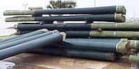
3 PILE TYPES: Timber Steel Concrete

4 TIMBER PILE


5 Pipe Pile STEEL PILE H-Pile

6 STEEL PIPE PILE 10/16/2013

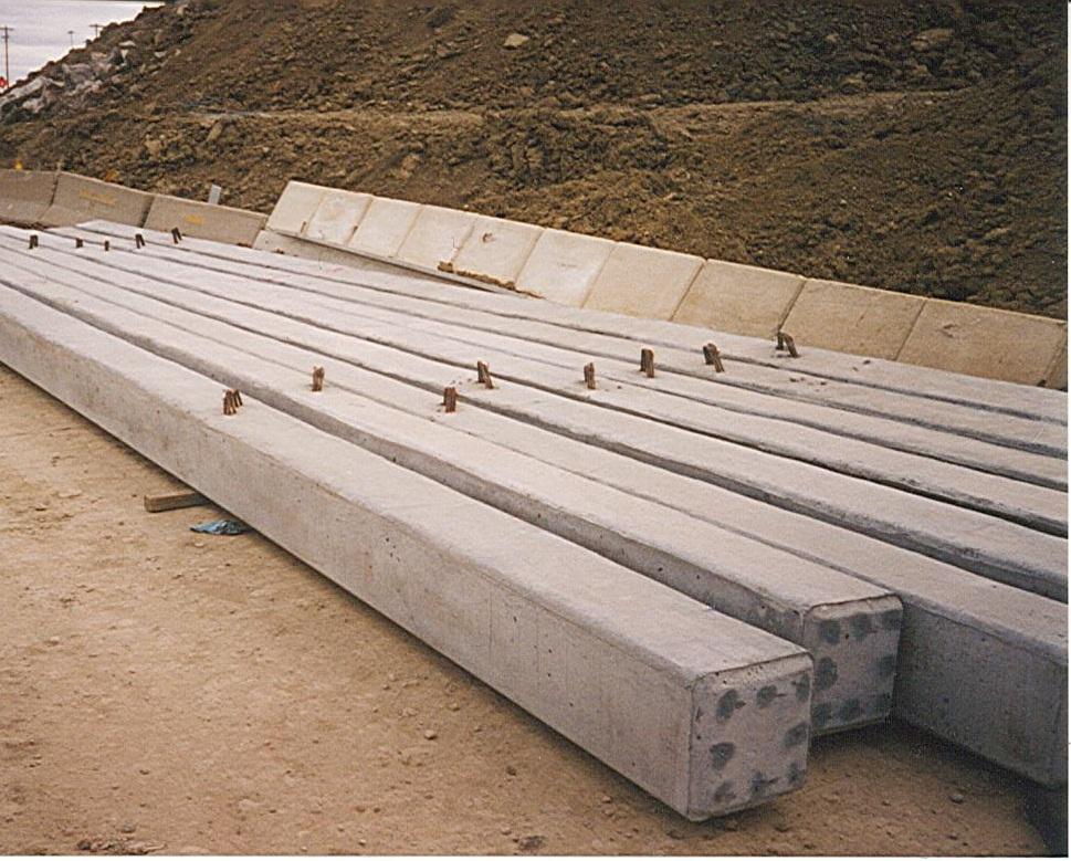
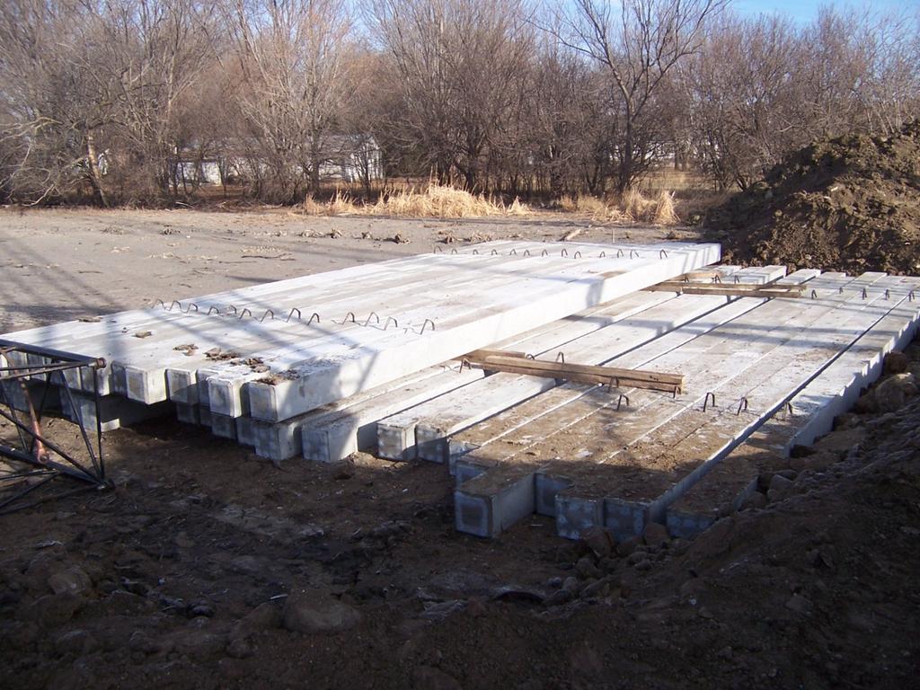
7 CONCRETE PILE
8
9 INSPECTION OF STEEL PILES Certificate of Compliance/Mill Test Report Chemical and Physical Tests Heat Numbers Made in the USA (Example on pg 5-62, Fig 5.10) Visual Inspection Size, Heat #, Defects, etc. Document

10
11 CONCRETE PILE INSPECTION Should Be Shop Inspected Region Materials plant Gage Brothers or SD Concrete Visual Inspection Conformance to Plans Cracks 100% Chips > 10% Proper lift procedure

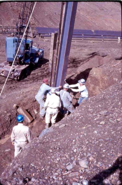
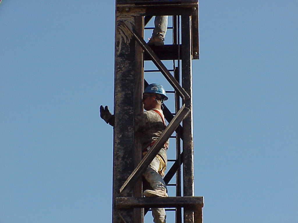
12 PROPER HANDLING AND LIFTING
13 PILE DRIVER Hammer Cap Leads Page 5-64, Figure 5.12
14 TYPES OF PILE DRIVERS Single Acting Hammer Double Acting Hammer Vibratory Hammer (Not Allowed)
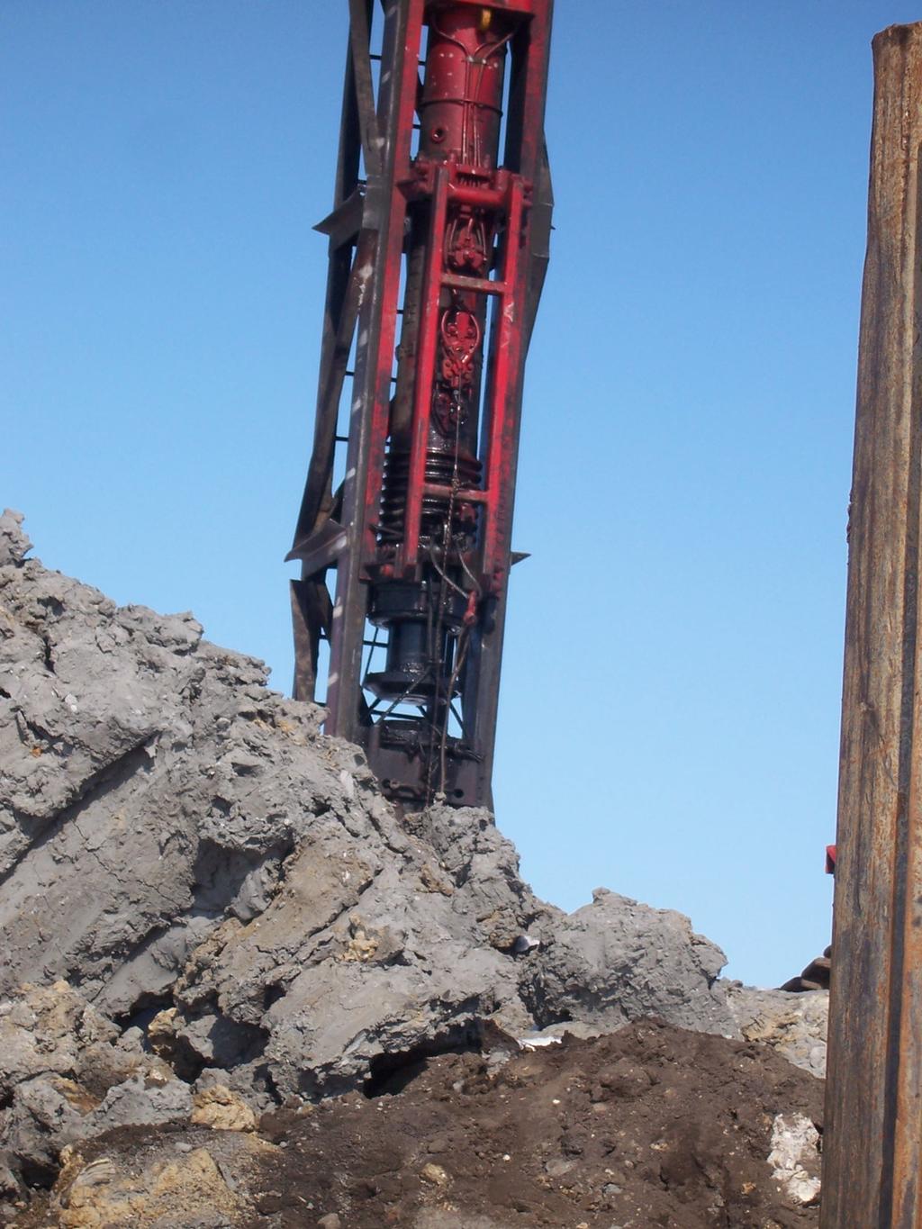
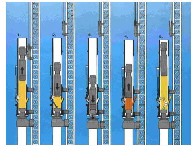
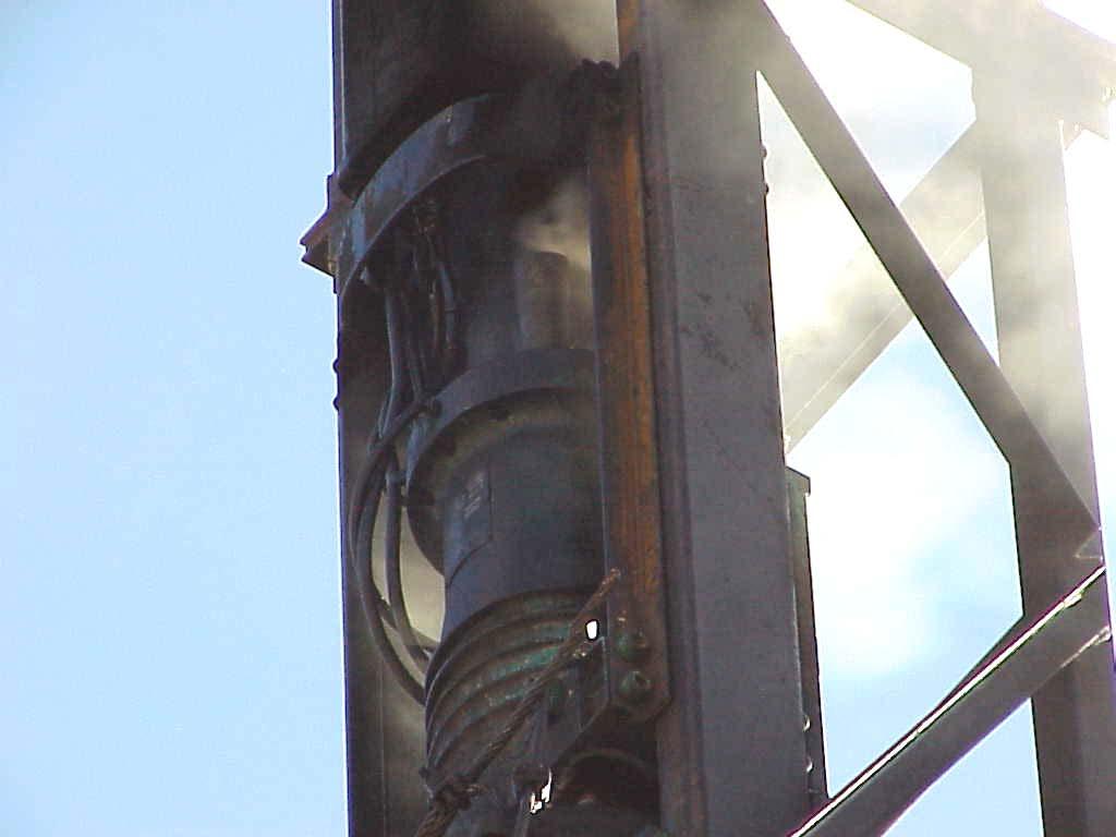
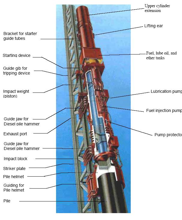
15 SINGLE ACTING HAMMER Can be Air, Steam, or Diesel Fueled Moving Piston Inside Stationary Cylinder Leads Guide Piston Cylinder Explosion Chamber Anvil Pad Cap Pg 5-65, Fig 5.13

16
17
18
19 DOUBLE ACTING HAMMER Bounce Chamber Leads Guide Explosion Chamber Explosion Chamber Bounce Chamber Piston Cylinder Explosion Chamber Anvil Pad Cap (pg 5-64) Table 5.16


20 DOUBLE ACTING HAMMER S 10/16/2013

21 BACK PRESSURE GAGE AND HOSES
22 ENERGY CHART


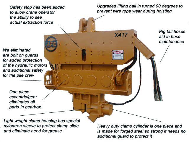
23 Vibratory Pile Driving Hammers
24 SUBSURFACE INVESTIGATION SHEET Upper Half Structure Location Project Centerline Piling Layout Test Hole Locations Lower Half Geographic profile Boring Logs Soil Formations Blow per foot graph Page 5-70 Fig 5.17

25 Subsurface Investigation Sheet 10/16/2013 Page 5-66, Fig 5.17
26 PRIMARY TYPES OF BEARING PICKUP Uniform Buildup Quick Buildup Double Buildup Page 5-71
27 TYPES OF BEARING PICKUP PAGE 5-71, FIG 5-18

28 DOUBLE BUILDUP 10/16/2013
29 DOUBLE BUILDUP ON TEST PILES Was the bearing 5-10 Tons more than the required bearing before it dropped off? Did the pile have more than the required bearing for at least 3 feet?
30 Test Pile Report DOT-203 (Pg 5-73) Pile Inspector s Report DOT-204 (Pg 5-74) PILE REPORTS
31 GENERAL INFO ON PILE REPORTS Project Number County Date Contractor Foundation Unit Structure Number Inspector s Name Structure Type Location Type of Pile Bearing Required Pile ID No.
32 DOT-203: PG 5-73, FIG /16/2013 DOT-203 (10/02) SHEET OF SOUTH DAKOTA DEPARTM ENT OF TRANSPORTATI ON I NSPECTOR'S TEST PI LE REPORT PROJECT NO. BRF 6599(03) PCEM S 6086 COUNTY Brown STR. # CONTRACTOR I BI FOUNDATI ON UNI T Abutment #! STR. TYPE 85' -0" Bulb Tee ON HWY OVER Foot Creek TYPE OF PI LE HP 10 X 42 I NSPECTOR TYPE AND NO. OF HAM M ER Single Acting Diesel STATION WEI GHT OF STRI KI NG PART 3,300 lbs REMARKS: WEI GHT OF CAP 1450 lbs CAP # A 146 WT OF ANVI L 1140 lbs REQ'D BEARING 192 DATE TEST PILE PILE SIZE ELEVATIONS PILE LENGTH PAY QUANTITIES NO. DIAMETER WT. PER LENGTH TOTAL LENGTH TIP BUTT FOOT BEGIN TOTAL WT. FINAL PLAN PLAN DRIVEN DRIVE PRE-BORE SPLICE (FT.) (FT) (LB.) (FT.) (FT.) (LBS) TIP CUTOFF GROUND WATER (FT.) (FT.) (FT.) (FT.) 1C AVG. OF LAST 10 BLOWS AVG. OF LAST 10 BLOWS AVG. OF LAST 10 BLOWS PILE IN PLACE DROP TOTAL PENT. BRG. PILE IN PLACE DROP TOTAL PENT. BRG. PILE IN PLACE DROP TOTAL PENT. BRG. LENGTH TIME "H" PENT. "S" "Q" LENGTH TIME "H" PENT. "S" "Q" LENGTH TIME "H" PENT. "S" "Q" (FT.) 0:00:00 (FT.) (IN.) (IN.) (TONS) (FT.) 0:00:00 (FT.) (IN.) (IN) (TONS) (FT.) 0:00:00 (FT.) (IN.) (IN.) (TONS) : : : : : : : : : : : : : : : : : : : : : NOTE: Sketch footing on reverse side and indicate position of this pile. Where pre-boring is required, use bottom of preboring as ground elevation. Remarks: Sketch need not be to scale. Show plan view of footing with position of test pile in relation to other piling, centerline of roadway,

33 DROP H VS PENT S 10/16/2013
34 OT-204 DOT-204: PG 5-74, FIG /16/2013 0/02) SHEET OF SOUTH DAKOTA DEPARTM ENT OF TRANSPORTATI ON PI LE I NSPECTOR'S REPORT ROJECT NO. Brf 6599(03) PCEM S 6086 COUNTY Brown STRUCTURE # ONTRACTOR I BI TR. TYPE 85' bulb T ON HWY OVER Foot Creek YPE OF PI LE HD 10 X 42 STATION EIGHT PER FOOT (piling) 42 lbs/ft YPE AND NO. OF HAM M ER Single Acting Diesel REQ'D BEARI NG 192 tons EI GHT OF STRI KI NG PART 3,300 lbs PLAN LENGTH 52.0 ft EI GHT OF CAP 1450 lbs CAP # A146 WT OF ANVI L 1140 lbs I NSPECTOR DATE LOCTION PILE SIZE ELEVATIONS AVG. OF LAST 10 BLOWS LENGTH PAY QUANTITIES OF PILE DIAMETER LENGTH (FT) WT. DROP TOTAL PENT. BRG. CUTOFF DRIVE PRE- SPLICE SUB-UNIT NO TIP BUTT BEGIN TOTAL (LBS) TIP CUTOFF GRD. WATER (FT) PENT. "S" "Q" (FT) (FT) BORE A 2 2A A 2 2B A 2 2C A 2 2D A 2 2E A 2 2F COMMENTS :Bridge Design
35 Substructure Sketch
36 PRELIMINARY DATA NEEDED Determine Type and Model No. of Hammer Determine Weight of Striking Part Determine Weight and No. of Cap Determine the Bearing Required Determine the Weights of the Piles

37 HELMET AND INSERT 10/16/2013
38

39 STAMPED PILE CAP 10/16/2013
40 HAMMER/LEADS/CAP 10/16/2013
41 PREBORING PILING Integral Type Abutment New Fill Minimum Size Backfill With Coarse Sand Spec A.5 Pile Size Timber Pile HP 8 Piles HP 10 Piles HP 12 Piles Prebore Size Min. 2 Larger than Diameter of Pile 12 Inches 15 Inches 18 Inches HP 14 Piles 21 Inches Spec Book A.5, page 292
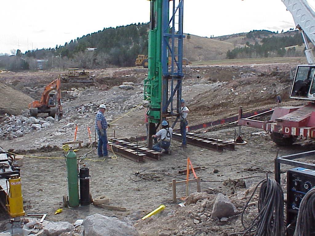
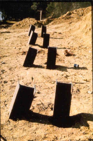
42 Remove Excavation PILE DRIVING Contractor Determines Correct Location (Inspector Verified) Check and Recheck Position and Batter After First Few Feet
43 LOCATION AND POSITION SPECIFICATIONS Piling are acceptable if they are within 6 of plans position. Battered pile must be within 1/4 in 12 of the plans specified batter. (Same for vertical pile)
44
45

46

47
48

49 10/16/2013 Page 5-75: Figure 5.22
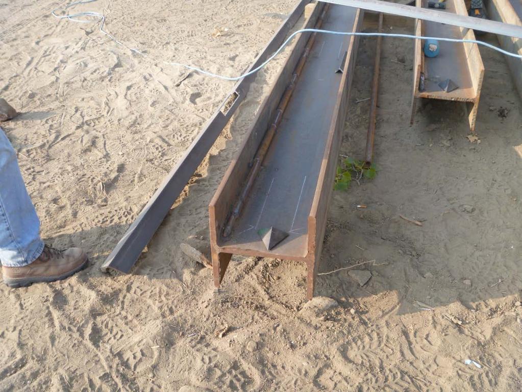
50 STEEL PILE TIPS Normal conditions: Materials ahead of pile tip forms its own point. Rocky Material Rock tip needed Near surface within 10 ft. Large boulders expected
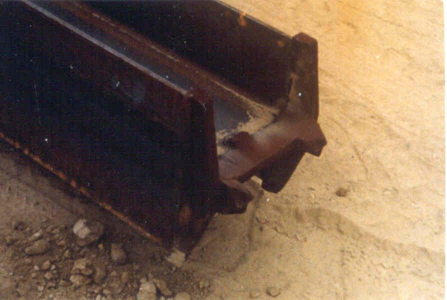

51 Reinforced Steel pile rock Tips
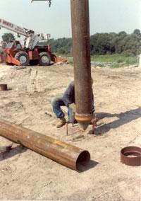
52 DRIVING PILE & COMPUTING BEARING 10/16/2013 Only drive pile 10 to 20%, more than plans required bearing. Pile need to be plumb or per spec batter Set pile, check alignment after a couple of feet. Start driving pile into ground Take readings every 5 ft & 1 ft after bearing achieved up to 10 20% over bearing.
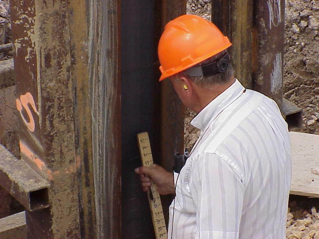
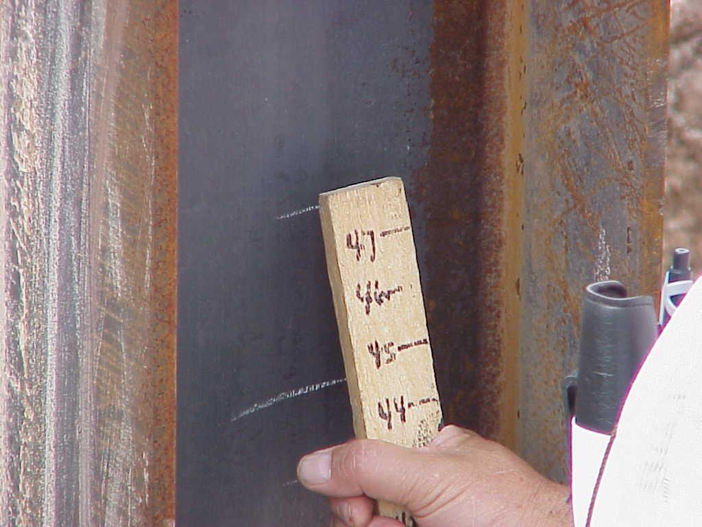
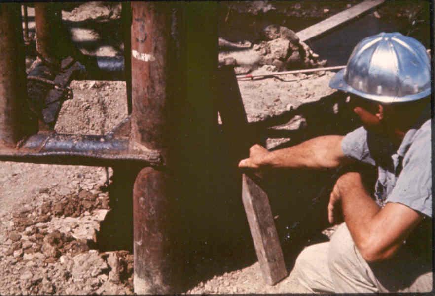
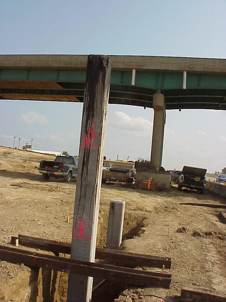
53 MEASURING PILE PENETRATION Place mark on piling. Drive the required number of blows 10 blows for Steel Pile 5 blows for Timber Pile Place another mark on the piling. Measure the distance between the marks.
54
55
56 Pile Driving Video Pile drive measurement sax.mpg
57

58

59
60 HAMMER FALL Single & Double Acting Hammers Meets the minimum energy per plans Hammer operating efficiently Uniform driving rates Hammers must have the capability to drive 1 inch in 10 blows
61 NEW PILE DRIVING FORMULA LRFD Platform: To determine the ultimate bearing capacity of driven piles The SDDOT uses the following formulas for timber, concrete, steel H-piling and shell type piles.
62 BEARING DETERMINATION SINGLE ACTION STEAM, AIR OR OPEN CYLINDER TOP DIESEL HAMMERS: Q (drive) = 10.5WH X W S W + M Where: Q = the nominal pile bearing resistance in tons W = the weight of a gravity hammer, or the ram of an energy hammer in tons. H = the height of free fall of the hammer or ram in feet. M = the weight in tons of the driven mass and shall include the weight of the pile, the weight of the driving cap and the weight of the anvil, if used. E = the energy per blow in foot-tons. S = the average penetration in inches of the pile per blow for the last five blows or gravity hammers and last 10 blows for energy hammers.
63 PENETRATION AT BEARING (SINGLE ACTING HAMMERS) 10/16/2013 S = {(10.5WH/Q) x (W/(W+M))} Q = Bearing (0.1 Tons) W = Weight of the Hammer (0.01 Tons) H = Free Fall of the Hammer (0.1 Feet) S = Pile Penetration in 1 Blow (0.01 Inches) M = Weight of the Driven Mass (0.01 Tons) Page 5-85, Fig 5.32
64 BEARING DETERMINATION DOUBLE ACTION STEAM OR AIR HAMMERS AND CLOSED CYLINDER TOP DIESEL HAMMERS: Q (drive) = 10.5E X W S W + M Where: Q = the nominal pile bearing resistance in tons W = the weight of a gravity hammer, or the ram of an energy hammer in tons. H = the height of free fall of the hammer or ram in feet. M = the weight in tons of the driven mass and shall include the weight of the pile, the weight of the driving cap and the weight of the anvil, if used. E = the energy per blow in foot-tons. S = the average penetration in inches of the pile per blow for the last five blows or gravity hammers and last 10 blows for energy hammers.

65 ENERGY CHART
66 PENETRATION AT BEARING (DOUBLE ACTING HAMMERS) 10/16/2013 S = {(10.5E/Q) x (W/(W+M))} Q = Bearing (0.1 Tons) W = Weight of the Hammer (0.01Tons) E = Energy Per Blow (0.01 Foot-Tons) S = Pile Penetration in 1 Blow (0.01 Inches) M = Weight of the Driven Mass (0.01 Tons) Page 5-85, Fig 5.27
67 TYPICAL PLAN NOTE
68 EXAMPLE: THE BOUNCE CHAMBER PRESSURE MEASURED OFF A DOUBLE ACTING HAMMER WAS 15.5 PSI. WHAT IS THE ENERGY DELIVERED TO THE PILE? Bounce Chamber Pressure vs. Equivalent WH Energy 22.5 Bounce Chamber Pressure (psig) Equivalent WH Energy (ft-lbs.)
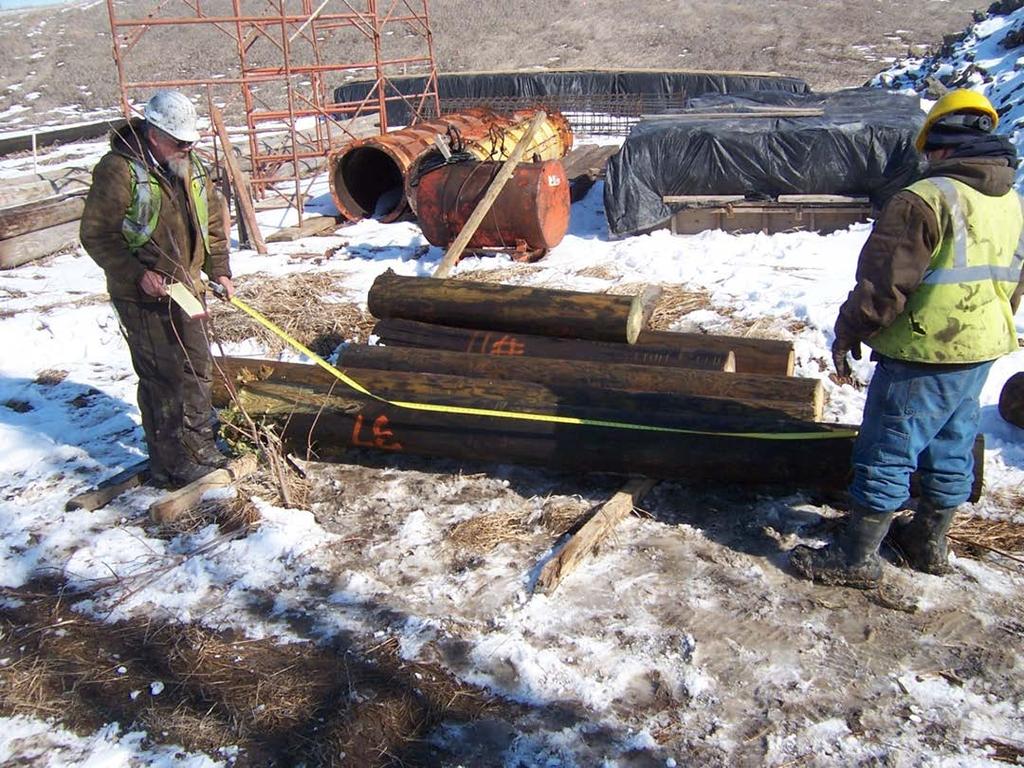
69 EX: DETERMINE TIMBER PILE WEIGHT. Cedar Pile = 25 ft Tip Measurements Butt Measurements Page 5-56, Fig 5.6 Page 5-82, Fig /16/2013 Dia: Min = 8.5 Inches Max = 10 Inches Circumference = 28.5 Inches Dia: Min = 15.5 Inches Max = 17.0 Inches 3ft from End = 50 Inches
70 FIRST COMPUTE DIAMETERS Tip Dia: 28.5 /3.14 = 9 Inches Butt Dia: 50 /3.14 = 16 Inches Wt/Ft = Use Fig 5.30???????

71 Page 5-82 Fig 5.30 Wt/Ft = lbs/ft
72 EXAMPLE PROBLEM #1 A SINGLE ACTION HAMMER WEIGHING 3920 LBS. AND A CAP WEIGHING 485 LBS. IS USED TO DRIVE A 40.0 FOOT LONG TIMBER TEST PILE THAT HAS A TIP DIAMETER OF 10.0 INCHES AND A BUTT DIAMETER OF 13 INCHES. THE HAMMER IS FREE FALLING 7.5 FEET AT A UNIFORM RATE RESULTING IN 6.5 INCH PENETRATION IN 10 BLOWS. WHAT IS THE COMPUTED BEARING OF THIS PILE? Q = (10.5WH/(S+0.10)) x W/(W+M) W = M = H = S = Hint: Use table on page 5-84, Fig 5.30.
73 SOLUTION FOR EXAMPLE PROBLEM #1: Q = (10.5WH/(S+0.10)) x W/(W+M) W = 3920 lbs / 2000 lbs/ton = 1.96 tons M = {485 lbs + (40.0 lf x lbs/lf)} / 2000 lbs/ton = 0.97 tons H = 7.5 Ft S = 6.5 in /10 blows = 0.65 in/blow Q = ((10.5 x 1.96 x 7.5)/( )) x 1.96 / ( ) Q = x 0.67 = tons
74 EXAMPLE PROBLEM #2 A ICE 60S single acting diesel hammer with a piston weight of 7000 lbs is used to drive a feet long HP 12 x 74 pile in an abutment to a bearing of 343 tons. The weight of the cap and insert is 1715 lbs and the manufacturer s weight of the anvil is 1246 lbs. If the average drop height is 8.5 feet in 10 blows, what would be the required penetration? Equation: S = {(10.5WH/Q) x (W/(W+M))} 0.1
75 ANSWER TO # 2 Equation: S = {(3WH/Q) x (W/(W+M))} 0.1 Q = 343 tons 10/16/2013 W = 7000lbs / 2000lbs/tons = 3.5 tons M = 201.7ft x 74 lbs/ft lbs lbs/ 2000 lbs/ton = 8.94 tons H = 8.5 ft S = {(10.5 x 3.5 x 8.5 / 343) x (3.5 / ( ))} 0.1 S = (0.91 x 0.28) 0.1 S = 0.15 in/ blow or 1.5 inches in 10 blows
76 EXAMPLE PROBLEM #3 10/16/2013 A DOUBLE ACTING DIESEL PILE HAMMER IS DRIVING A 70 FT HP 10X42 TEST PILE WITH A 7000 LB PISTON. THE BACK PRESSURE READING AT THE TIME DRIVING CEASED WAS READ ON THE GAGE TO BE 19.0 PSI USING THE CHART ON PAGE THE WEIGHT OF THE ANVIL AND CAP WAS KNOWN TO BE 1500 LBS. THE DESIGN BEARING IS 192 TONS, WHAT WOULD THE NECESSARY PENETRATION FOR OBTAINING 20% ABOVE PLAN BEARING IN 10 BLOWS. S = {(10.5E/Q) x (W/(W+M))} 0.1
77 ANSWER TO #3: P: Plan Bearing = 192 tons 20% over bearing = 192 x 1.20 = tons W = 7000/2000 = 3.50 tons M = ((42 x 70) )/2000 = 2.22 tons E = 13600/2000 = 6.8 ft-tons S = {(3E/Q) x (W/(W+M))} % over for test pile S = {(10.5x6.8/230.4) x (3.50/( ))} -0.1 = 0.08 in S = 0.31 x = 0.09in/blow or 0.9 inches in 10 blows
78 BATTER FACTORS Batter Factor = cosine a - f sin a a = Angle between the leads and a vertical line f = Coefficient of friction between hammer and surface it slides on (typically 0.1) Batter Factors 1 on on on on on on

79 Batter Pile Driving
80 WHEN TO STOP DRIVING Test Pile % Over Plans Bearing Location near center of substructure unit Verify Bearing Build-up type & check subsurface investigation sheet Bearing Pile - Stop When Bearing is Achieved Prevent overdriving
81 TEST PILE LOCATIONS: 10/16/2013
82 SET-UP EFFECT 10/16/2013 Stop Driving When Pile is Two Feet Above Cutoff Elevation Let Set For 24 Hours Warm up the Hammer on Another Pile Reset the Cap (2-3 Blows) Take Measurement on Next 10 Blows
83 Setup Video: 101_3336a.wmv 10/16/2013
84 DRIVING PILING NEAR FRESH CONCRETE Vibrations Adversely Affect Fresh Concrete 24 Hour Waiting Period Glass of Water Method
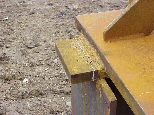
85 PILE SPLICES 10/16/2013 Timber Snug Fit? Properly Treated? Steel Certified Welder Needed? Sec 410 of Standard Specifications Prevent splice in upper 10 ft in an integral abutment or pile frame bent. Concrete?

86
87 PILE SPLICE STANDARD PLATES
88 PILING CUTOFF Shoot with rod and level from benchmark. Measure length in place to nearest 0.1 ft. No payment for cutoff unless ordered re-driven.

89 Measuring Pile Cutoff
90
91 PAYMENT 10/16/2013 FURNISH & DRIVE TEST PILE Test Piles Paid to the nearest 1.0 LF. Driven greater than plans quantity - pay quantity driven. Driven Less than plan quantity pay plans quantity. Section page 296
92 PAYMENT FURNISH & DRIVE BEARING PILE Paid to the 1.0 LF driven. Final quantity > plans 10/16/2013 Pay contract price for driven quantity + 10% of unit price for difference. Final Quantity < plans: Pay contract price for driven quantity If driven is underrun by > 5ft x # pile + 20% for entire difference. Section B.1&2
93 EXAMPLE: Ten HP 12x74 required in the contract Contract Price to Furnish and Drive HP 12x74 = $15.00/LF Plans quantity: HP 12 x 74 = 250 LF Driven quantity: HP 12 x 74 = 195 LF ============================== Difference = 55 LF 10 pile x 5ft = 50 ft. Since the difference was greater than 50 LF, adjust payment as follows: Pay the quantity driven at the contract price plus: 55 LF x $15.00/LF x 0.2 = $165.00
94 PILE SPLICE PAYMENT: Within the specified pile length No payment Located at or beyond specified length: Measure per each for payment

95 SAXIMETER Automatically counts the hammer blows and determines blows per minute. Automatically calculates the fall height for single action hammers.
96
97 PILE RESEARCH Static Load Test and Dynamic Testing Inspection Requirements
98 PILE RESEARCH Review all contract documents Plans Special Provision Spec Book Shop-plans
99 STATE OF SOUTH DAKOTA DEPARTMENT OF TRANSPORTATION 10/16/2013 SPECIAL PROVISION FOR DYNAMIC PILE MONITORING AND STATIC PILE LOAD TESTING PROJECT NUMBER, PCN NUMBER NAME COUNTY SEPTEMBER 2, 2011 I. DESCRIPTION This work shall consist of furnishing all labor, equipment, materials and qualified personnel necessary to conduct dynamic monitoring and static load testing of driven piles in accordance with this special provision at locations designated in the plans or as directed by the Engineer. Dynamic monitoring and static load testing of two HP 12 X 74 steel test piles along with the dynamic monitoring of four HP 12 X 74 steel production piling shall be performed by the Contractor. The purpose of this testing program is to obtain load-deflection and load transfer data required to accurately determine the nominal resistance of the pile under static loading conditions for comparison and correlation with dynamic driving data predictions and subsequent calibration of Load and Resistance Factor Design (LRFD) load factors based on local practice. The Contractor shall engage the services of a specialty subcontractor experienced in high-strain dynamic monitoring and static load testing of driven piles to perform the tasks listed in this special provision and report results to the Department. The specialty subcontractor shall have at least five years of documented experience in the performance and interpretation of dynamic and static pile testing. The individual responsible for operating the instrumentation shall be under the direct supervision of a licensed Professional Engineer registered in the state of South Dakota and be fully capable of understanding and interpreting the data being collected. The specialty subcontractor shall be selected by the Contractor and submitted for approval, by the Engineer, a minimum of 30 days prior to work beginning. Approval will be based upon qualifications and applicable previous experience on other projects.
100 PILE RESEARCH 30 days prior to the start of pile driving Testing Company information submitted Pre construction wave equation Load frame design submitted Including reaction Pile driving sequence and bearing Jack and Load Cell calibration certification submitted Both need to be calibrated within 60 days of use
101 STATIC LOAD TEST Test pile must be driven in order as per special provision Each test will have different number of days to restrike as per special provision SDDOT inspectors will need to locate area for test pile to be driven SDDOT inspectors need to witness reaction pile driving to insure proper bearing and placement as per load test frame design
102 Inspector will need to provide saximeter and monitor static test piles being driven Provide data for each foot of pile being driven or as requested by testing company Provide inspector pile report Static load test will be ran by testing company Inform Foundations when test will be performed
103 Dynamic testing will be performed on piles in substructure Inspectors will monitor pile driving the same as normal projects Testing company will place monitoring equipment on pile when hammer is in place Measurement will be done according to test pile section in SDDOT spec. book

104

105 DYNAMIC TESTING OF PILE Pile Dynamic Analysis

106 DYNAMIC TEST
107

108 STATIC LOAD TEST

109 PILE STATIC LOAD TEST 10/16/2013

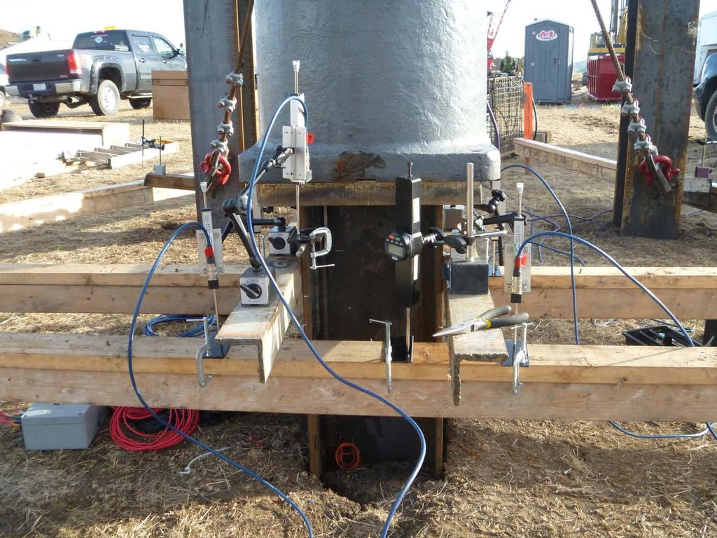
110 STATIC LOAD TEST 10/16/2013 INSTRUMENTATION
111
112 STATNAMIC LOAD TEST

113


114 DAMAGED PILE DUE TO OVERDRIVING 10/16/2013
115 PRECAUTIONS IN PILE DRIVING Drive Pile Axially Prevent Overdriving Significant Hammer Energy Keep Piston Cable Slack Preventing the Hammer from Bouncing Hammer operating properly

116
117 QUESTIONS Office of Bridge Design: Bridge Construction Engineer: Hadley Eisenbeisz Office # = Cell:
OFFICE OF STATE AID ROAD CONSTRUCTION MISSISSIPPI DEPARTMENT OF TRANSPORTATION
 Supplemental Specification 901-S-803-1 LFRD Driven Pile Specifications. DATE: May 24, 2010 OFFICE OF STATE AID ROAD CONSTRUCTION MISSISSIPPI DEPARTMENT OF TRANSPORTATION SUBJECT: LRFD Driven Pile Specifications
Construction Planning, Equipment, and Methods PILES AND PILE-DRIVING EQUIPMENT
 CHAPTER Construction Planning, Equipment, and Methods PILES AND PILE-DRIVING EQUIPMENT Sixth Edition A. J. Clark School of Engineering Department of Civil and Environmental Engineering 19 By Dr. Ibrahim
Lesson 3 Construction Documents Transcript. Welcome to the Pile Driving Inspector Course. This is Lesson 3 Construction Documents.
 Lesson 3 Construction Documents Transcript Welcome to the Pile Driving Inspector Course. This is Lesson 3 Construction Documents. To begin, select the start button or press Shift+N on your keyboard. In
THE PILE DRIVING SYSTEM
 Version 1.0-1/2015 Page 2-1 Lesson 2 THE PILE DRIVING SYSTEM 2-1 Version 1.0-1/2015 Page 2-2 Learning Outcomes Identify Pile Installation Equipment and Tools Identify various pile types Use Pile Driving
SAMPLE SPECIFICATION for HIGH STRAIN DYNAMIC TESTING of DRIVEN PILES
 SAMPLE SPECIFICATION for HIGH STRAIN DYNAMIC TESTING of DRIVEN PILES October 2014 In using this sample specification, it should be recognized that each site and structure is unique. Therefore, geotechnical
Lesson 4 INSPECTOR S ROLE
 Lesson 4 INSPECTOR S ROLE 4-1 Version 1.0-1/15 4-1 Learning Outcomes Identify and understand the Role and Duties of the Inspector Assemble Your Tool Box Identify and Understand Pay Items/Quantities Perform
LOAD FACTOR RESISTANCE DESIGN
 LRFD LOAD FACTOR RESISTANCE DESIGN HOW CONSTRUCTION ACTIVITIES & SPECIFICATIONS ARE AFFECTED LOUISIANA TRANSPORTATION CONFERENCE 2009 Kim Martindale Garlington, P.E. LADOTD Pavement and Geotechnical Engineer
Testing Methods of Driven Piles on INDOT Demonstration Projects
 66 Testing Methods of Driven Piles on INDOT Demonstration Projects by Firooz Zandi, P.E. Chief Geotechnical Engineer Division of Materials & Tests, I NDOT INTRODUCTION: This paper provides an overview
WELCOME TO THE PILE DRIVING INSPECTOR COURSE
 Lesson 1 WELCOME TO THE PILE DRIVING INSPECTOR COURSE 1-1 Welcome to the Pile Driving Inspector Course. This is a course designed to assist students to understand the specifications and inspection practices
ADDENDUM No. 6. ITB No. 4424: W.R. Wheeler (Swift Run) Service Center PUD Non-motorized Improvements Phase 1
 Service Center PUD Non-motorized Improvements Phase 1") ADDENDUM No. 6 ITB No. 4424: W.R. Wheeler (Swift Run) Service Center PUD Non-motorized Improvements Phase 1 Due: June 9, 2016 at 2:00 p.m. (local time) The following changes, additions, and/or deletions
ADDENDUM No. 6 ITB No. 4424: W.R. Wheeler (Swift Run) Service Center PUD Non-motorized Improvements Phase 1 Due: June 9, 2016 at 2:00 p.m. (local time) The following changes, additions, and/or deletions
Bi-Directional Static Load Testing of Driven Piles
 Bi-Directional Static Load Testing of Driven Piles Paul J. Bullock, PhD Fugro Consultants Inc. Loadtest Bi-Directional Osterberg Cell Testing Specialized jack in pile uses bearing to mobilize side shear
DIVISION 31 EARTHWORK 2006 Edition, Published January 1, 2006; Division Revision Date: January 31, 2012
 2006 Edition, Published January 1, 2006; Division Revision Date: January 31, 2012 PART FIVE DOCUMENTS FOR SITE AND INFRASTRUCTURE 31 00 00. EARTHWORK 31 10 00. SITE CLEARING.1 STRUCTURE REMOVAL: Include
SECTION PILING
 02300-1 of 16 SECTION 02300 PILING 02300.01 GENERAL A. Description Piling shall include, but not necessarily be limited to, the manufacturing, furnishing, treating, painting, coating, driving, jetting,
JOB BB0113 SHELL LAKE STR. & APPRS. (S) MARCH 10, 2015 LETTING QUESTIONS PREVIOUSLY ASKED UNDER JOB BB0106.
 MARCH 10, 2015 LETTING QUESTIONS PREVIOUSLY ASKED UNDER JOB BB0106.") JOB BB0113 SHELL LAKE STR. & APPRS. (S) MARCH 10, 2015 LETTING QUESTIONS PREVIOUSLY ASKED UNDER JOB BB0106. There are notes in the plans regarding driving the test pile without the use of a follower. The
JOB BB0113 SHELL LAKE STR. & APPRS. (S) MARCH 10, 2015 LETTING QUESTIONS PREVIOUSLY ASKED UNDER JOB BB0106. There are notes in the plans regarding driving the test pile without the use of a follower. The
GEOTECHNICAL RESISTANCE FACTORS
 Chapter 9 GEOTECHNICAL RESISTANCE FACTORS Final SCDOT GEOTECHNICAL DESIGN MANUAL 9-i Table of Contents Section Page 9.1 Introduction... 9-1 9.2 Soil Properties... 9-2 9.3 Resistance Factors for LRFD Geotechnical
SPECIFICATIONS FOR PRECAST MODULAR BLOCK RETAINING WALL SYSTEM (revised 5/8/7)
") Page 1 of 7 STONE STRONG SYSTEMS SPECIFICATIONS FOR PRECAST MODULAR BLOCK RETAINING WALL SYSTEM (revised 5/8/7) PART 1: GENERAL 1.01 Description A. Work includes furnishing and installing precast modular
Page 1 of 7 STONE STRONG SYSTEMS SPECIFICATIONS FOR PRECAST MODULAR BLOCK RETAINING WALL SYSTEM (revised 5/8/7) PART 1: GENERAL 1.01 Description A. Work includes furnishing and installing precast modular
SPECIFICATION : BORING AND JACKING
 SPECIFICATION 330524: BORING AND JACKING PART 1.0 GENERAL 1.1 DESCRIPTION 1.1.1 The work of this specification includes all labor, machinery, construction equipment and appliances required to perform in
Implementation of the AASHTO LRFD Code
 Implementation of the AASHTO LRFD Code in the NDOR Practice Di Driven Piles Andrzej S. Nowak, Marek Kozikowski, Tomasz Lutomirski, Piotr Paczkowski University of Nebraska-Lincoln and Omar Qudus and Jordan
DIVISION 33 - UTILITIES SECTION UTILITY PIPE BORING AND JACKING DIVISION 33 UTILITIES SECTION UTILITY PIPE BORING AND JACKING
 DIVISION 33 UTILITIES PART 1 GENERAL 1.01 SCOPE A. This work shall consist of the underground construction of a pipeline across the state right-ofway, or other facility as indicated on the plans and as
Offshore pile acceptance using dynamic pile monitoring
 Offshore pile acceptance using dynamic pile monitoring Webster, S. & Givet, R. GRL Engineers, Inc. Charlotte, NC, USA Griffith, A. Saudi Aramco, Dhahran, Saudi Arabia ABSTRACT: Dynamic pile monitoring
SECTION PERMEABLE INTERLOCKING CONCRETE UNIT PAVEMENT
 SECTION 32 14 13 19 PERMEABLE INTERLOCKING CONCRETE UNIT PAVEMENT SECTION 32 14 13 19 PERMEABLE INTERLOCKING CONCRETE UNIT PAVEMENT PART 1 - GENERAL 1.1 SUMMARY A. Section Includes: 1. Permeable Articulating
SECTION SPECIFICATION FOR STONEBRIDGE RETAINING WALL SYSTEM
 SECTION 32 32 23 SPECIFICATION FOR STONEBRIDGE RETAINING WALL SYSTEM PART 1: GENERAL 1.01 Scope Work includes furnishing all materials, labor, equipment, and supervision to install a Stonebridge segmental
Structural Tests and Special Inspections Form. Inspection of Fabricators (1704.2)
") Inspection of Fabricators (1704.2) Furnish inspection reports (1704.2.1) - Fabricators that have not been approved Provide a Certificate of Compliance (1704.2.2) - Approved Fabricators Steel Construction
Inspection of Fabricators (1704.2) Furnish inspection reports (1704.2.1) - Fabricators that have not been approved Provide a Certificate of Compliance (1704.2.2) - Approved Fabricators Steel Construction
Construction Procedures
 Construction Procedures 2014 Rev. 1.6 1 Introduction This manual presents the methods and procedures necessary for the proper erection of a LOCK+LOAD retaining wall. problems later during the service life
Standards for Testing and Rating Shoring Equipment
 ANSI/SSFI SH300-2007 American National Standard Standards for Testing and Rating Shoring Equipment Scaffolding, Shoring & Forming Institute, Inc. Sponsor: Scaffolding, Shoring & Forming Institute, Inc.
SECTION A1 EXCAVATION AND BACKFILL GENERAL
 SECTION A1 EXCAVATION AND BACKFILL GENERAL The work under this section shall include all excavation to such width and depth as shown on the drawings, specified herein, or ordered by the Engineer. Such
Pile Driving Analyzer (PDA) and CAPWAP Proven Pile Testing Technology: Principles and Recent Advances
 and CAPWAP Proven Pile Testing Technology: Principles and Recent Advances") Pile Driving Analyzer (PDA) and CAPWAP Proven Pile Testing Technology: Principles and Recent Advances Frank Rausche, Ph.D., P.E. Pile Dynamics, Inc. 2013 Louisiana Transportation Conference 1 Introduction
Pile Driving Analyzer (PDA) and CAPWAP Proven Pile Testing Technology: Principles and Recent Advances Frank Rausche, Ph.D., P.E. Pile Dynamics, Inc. 2013 Louisiana Transportation Conference 1 Introduction
DESIGNING AND CONSTRUCTION OF T-WALL RETAINING WALL SYSTEM
 Istanbul Bridge Conference August 11-13, 2014 Istanbul, Turkey DESIGNING AND CONSTRUCTION OF T-WALL RETAINING WALL SYSTEM T. C. NEEL and K.BOZKURT ABSTRACT This work shall consist of the design, manufacture
Development of LRFD Procedures for Bridge Piles in Iowa Volume IV: Design Guide and Track Examples
 InTrans Project Reports Institute for Transportation 5-2012 Development of LRFD Procedures for Bridge Piles in Iowa Volume IV: Design Guide and Track Examples Donald Green Michael Baker Jr., Inc. Kam W.
1. Cast-in-place concrete is specified in Section
 SECTION 03 38 00 PART 1 - GENERAL 1.01 DESCRIPTION A. This Section describes the requirements for furnishing and installing post-tensioned slabs, jacks, jacking and anchors at Parking Structure, and record
SECTION 19 - TRENCH EXCAVATION, BEDDING AND BACKFILL TABLE OF CONTENTS
 SECTION 19 - TRENCH EXCAVATION, BEDDING AND BACKFILL TABLE OF CONTENTS Section Page 19-1 TRENCH EXCAVATION...19.1 19-1.01 Exploratory Excavation...19.1 19-1.02 Trench Width...19.1 19-1.02.A Storm Drain
Project Address: Name of Person Completing Form:
 Statement of Inspections This form is provided as a way to list aspects of the project that require special inspection and testing in accordance with IBC Sections 107.1, 1704, and 1705 and define duties
UNIFIED FACILITIES GUIDE SPECIFICATIONS
 USACE / NAVFAC / AFCEC / NASA UFGS-31 62 21 (November 2008) ----------------------------- Preparing Activity: USACE Superseding UFGS-31 62 21 (April 2006) UNIFIED FACILITIES GUIDE SPECIFICATIONS References
TRENCHLESS CONSTRUCTION (BORING, JACKING, AND TUNNELING)
") PART 1 - GENERAL TRENCHLESS CONSTRUCTION (BORING, JACKING, AND TUNNELING) 1.01 SECTION INCLUDES A. Trenchless Installation of Carrier Pipe with Casing Pipe B. Trenchless Installation of Carrier Pipe without
PART 1 - GENERAL TRENCHLESS CONSTRUCTION (BORING, JACKING, AND TUNNELING) 1.01 SECTION INCLUDES A. Trenchless Installation of Carrier Pipe with Casing Pipe B. Trenchless Installation of Carrier Pipe without
SEGMENTAL BLOCK RETAINING WALLS. Comply with Division 1 - General Provisions and Covenants, as well as the following:
 SEGMENTAL BLOCK RETAINING WALLS PART 1 - GENERAL 1.01 SECTION INCLUDES Segmental Block Retaining Walls 1.02 DESCRIPTION OF WORK Constructing segmental block retaining walls. 1.03 SUBMITTALS Comply with
CHANGES IN 2006 SPECIFICATIONS SECTION 804 DRIVEN PILES SECTION 814 DRILLED SHAFTS
 CHANGES IN 2006 SPECIFICATIONS SECTION 804 DRIVEN PILES SECTION 814 DRILLED SHAFTS 2006 LADOTD ENGINEERING CONFERENCE Kim Martindale Garlington, P.E. Pavement & Geotechnical Services February 13, 2007
SPEEDY MOISTURE TEST. Equipment Needed: Complete speedy kit, No. 4 sieve, speedy chart, and sample of soil.
 SPEEDY MOISTURE TEST Equipment Needed: Complete speedy kit, No. 4 sieve, speedy chart, and sample of soil. Make sure moisture tester is clean and in good working order. Place three measures of calcium
Bridge Manual - Part I - June CHAPTER 5 SPECIAL PROVISIONS AND ESTIMATE
 Bridge Manual - Part I - June 2007 5-1 CHAPTER 5 SPECIAL PROVISIONS AND ESTIMATE 5.1 GENERAL This chapter is intended to instruct the Designer in the preparation and submission of Special Provisions and
LANDSCAPE RETAINING WALLS
 SUDAS Standard Specifications Division 9 - Site Work and Landscaping Section 9070 - Landscape Retaining Walls LANDSCAPE RETAINING WALLS PART - GENERAL.0 SECTION INCLUDES A. Modular Block Retaining Walls
SECTION CAST-IN-PLACE CONCRETE
 SECTION 03300 CAST-IN-PLACE CONCRETE PART 1 GENERAL 1.01 SECTION INCLUDES A. The Contractor shall furnish all work and materials, including cement, sand and coarse aggregate, water, admixtures, curing
SPECIFICATION FOR REINFORCED SOIL WALL
 SPECIFICATION FOR REINFORCED SOIL WALL 1.0 EXTENT OF WORK The work shall consist of Reinforced Soil walls built in accordance with this specification and in conformity with the lines, levels and details
S.No Description Unit Quantity Rate (Rs) Amount (Rs)
 Amount (Rs)") , S.No Description Unit Quantity Rate (Rs) Amount (Rs) 1 2 Vertical load testing of piles in accordance with IS 2911 (Part IV) including installation of loading platform by Kentledge method and preparation
, S.No Description Unit Quantity Rate (Rs) Amount (Rs) 1 2 Vertical load testing of piles in accordance with IS 2911 (Part IV) including installation of loading platform by Kentledge method and preparation
CONTINUOUS FLIGHT AUGER (CFA) PILES QC/QA PROCEDURES. Preferred QC/QA Procedures
 PILES QC/QA PROCEDURES. Preferred QC/QA Procedures") Preferred QC/QA Procedures The Federal Highway Administration (FHWA) has provided QC/QA guidance for this technology as noted below. The reference document also contains information about construction
Preferred QC/QA Procedures The Federal Highway Administration (FHWA) has provided QC/QA guidance for this technology as noted below. The reference document also contains information about construction
PREFABRICATED STEEL TRUSS SPECIFICATIONS
 PREFABRICATED STEEL TRUSS SPECIFICATIONS 1. GENERAL 1.1 Scope All engineering design and related detailing of the bridge(s) shall be provided by the supplier. The design and detailing shall conform to
SECTION C1 DUCTILE IRON PIPE AND FITTINGS GENERAL
 SECTION C1 DUCTILE IRON PIPE AND FITTINGS GENERAL This section covers the furnishing and installation of ductile iron water pipe, fittings, thrust restraint and pipe disinfection. Ductile Iron Pipe MATERIALS
CHEMICAL /4" 3/8" to 5/8" /8" 3/4" to 1-1/4" 1 10
 194 ASTM A193 GRADE B7 HIGH-STRENGTH CARBON, ZINC PLATED (ASTM B 633 YELLOW DICHROMATE) B7 (AISI 414) anchor rod is supplied with nuts meeting the requirements of ASTM Specification A 194, Grade 2H (ASTM
MKT VIBRATORY HAMMER SELECTION AND SOILS TRAINING
 MKT VIBRATORY HAMMER SELECTION AND SOILS TRAINING While reviewing this guide if you see this symbol please click to the next slide. Press the F5 key when you are ready to start the slide show. MKT MANUFACTURING,
***************************************************************************************************************
 03365 POST-TENSIONED CONCRETE *************************************************************************************************************** SPECIFIER: CSI MasterFormat 2004 number 03 38 00. ***************************************************************************************************************
SECTION 19 - TRENCH EXCAVATION, BEDDING AND BACKFILL TABLE OF CONTENTS
 SECTION 19 - TRENCH EXCAVATION, BEDDING AND BACKFILL TABLE OF CONTENTS Section Page 19-1 TRENCH EXCAVATION... 19.1 19-1.01 Exploratory Excavation... 19.1 19-1.02 Trench Width... 19.1 19-1.02.A Storm Drain
Standard Test Method for Piles Under Lateral Loads 1
 Designation: D 3966 90 (Reapproved 1995) Standard Test Method for Piles Under Lateral Loads 1 AMERICAN SOCIETY FOR TESTING AND MATERIALS 100 Barr Harbor Dr., West Conshohocken, PA 19428 Reprinted from
Page 10-1 Hubbell Power Systems, Inc. All Rights Reserved Copyright 2014 LIGHTING AND SIGNS
 Page 10-1 Hubbell Power Systems, Inc. All Rights Reserved Copyright 2014 FOUNDATION SYSTEM SECTION 10 CONTENTS INTRODUCTION... 10-3 PRODUCT BENEFITS... 10-3 RECOMMENDED FACTORS of SAFETY for DESIGN...
ODOT Design & Construction Requirements for MSE Walls
 ODOT Design & Construction Requirements for MSE Walls Peter Narsavage, P.E. Foundation Engineering Coordinator Ohio Department of Transportation Office of Structural Engineering 2006 Ohio Transportation
METHOD STATEMENT FOR PIPE WELDING WORKS
 METHOD STATEMENT FOR PIPE WELDING WORKS Introduction This Method statement describes in detail the welding process for pipe work and the welder s qualification test procedures. This includes addressing
Specification Lightning Protection Systems
 Specification Lightning Protection Systems General: Summary A) This Section specifies the lightning protection system for the building(s) or structure(s). This system provides safety for the building and
Chapter A-15. CID-MO Structural Analysis
 Kansas Citys, Missouri and Kansas Flood Risk Management Feasibility Study Engineering Appendix to the Final Feasibility Study Chapter A-15 CID-MO Structural Analysis Chapter A-15 CID-MO Structural Analysis
GREEN THREAD Piping Systems
 Bulletin No. A1300 February 15, 2006 SMITH FIBERCAST GREEN THREAD Piping Systems PRODUCT GREEN THREAD pipe is filament wound using an amine cured epoxy resin and fiberglass and has a resin-rich liner reinforced
SPECIFICATIONS FOR STREET CONSTRUCTION WITHIN THE TOWN OF PLAINVILLE
 SPECIFICATIONS FOR STREET CONSTRUCTION WITHIN THE TOWN OF PLAINVILLE BE IT ORDAINED by the Town Council of the Town of Plainville: SECTION 1. SUBDIVISIONS. All subdivisions hereinafter developed within
 techie-touch.blogspot.com www.vidyarthiplus.com CE2305 FOUNDATION ENGINEERING 2 MARKS QUESTIONS & ANSWERS 16 MARKS QUESTIONS UNIT -1 1. What are components of total foundation settlement? elastic settlement,
DIVISION: EARTHWORK SECTION: BORED PILES REPORT HOLDER: CANTSINK MANUFACTURING, INC. 71 FIRST AVENUE LILBURN, GEORGIA 30047
 0 Most Widely Accepted and Trusted ICC-ES Evaluation Report ICC-ES 000 (800) 423-6587 (562) 699-0543 www.icc-es.org ESR-1559 Reissued 12/2016 This report is subject to renewal 12/2018. DIVISION: 31 00
SECTION IV. PIPELINE EXCAVATION AND BACKFILL
 SECTION IV. PIPELINE EXCAVATION AND BACKFILL A. Description of Work B. Surface Types C. Backfill D. Surface Restoration A. DESCRIPTION OF WORK 1. Extent: Excavation of trenches for pipelines shall include
DIVISION: EARTHWORK SECTION: BORED PILES REPORT HOLDER: EMPIRE PIERS 2656 EAST HWY 47 WINFIELD, MO EVALUATION SUBJECT:
 0 Most Widely Accepted and Trusted ICC-ES Evaluation Report ICC-ES 000 (800) 423-6587 (562) 699-0543 www.icc-es.org ESR-4050 Issued 12/2017 This report is subject to renewal 12/2018. DIVISION: 31 00 00
Masonry Wall Bracing. A Simplified Approach To Bracing Masonry Walls Under Construction. Masonry Bracing Task Force.
 Masonry Wall Bracing A Simplified Approach To Bracing Masonry Walls Under Construction Produced by the Masonry Wall Bracing A Simplified Approach to Bracing Masonry Walls Under Construction Produced by
FRP Composite Piles Applications & Durability Considerations
 FRP Composite Piles Applications & Durability Considerations by Miguel A. Pando, Felipe J. Acosta, P.E. UPRM mpando@uprm.edu, facosta@uprm.edu Jack Lesko Virginia Tech Virginia Fiber-Reinforced Composites
SECTION HIGH DENSITY POLYETHYLENE PIPE AND FITTINGS
 SECTION 02620 PART 1 GENERAL 1.1 SCOPE OF WORK A. Furnish all labor, materials, equipment, and incidentals required to install High Density Polyethylene (HDPE) pressure pipe, fittings, and appurtenances
CONCRETE SEGMENTAL RETAINING WALL SYSTEM
 CONCRETE SEGMENTAL RETAINING WALL SYSTEM PART 1: GENERAL SPECIFICATIONS 1.01 Work Included A. Work shall consist of furnishing and constructing a Rockwood Classic 8, Classic 6 and Legend unit segmental
SECTION PREFABRICATED PIPE BRIDGE(s)
") SECTION 13135 - PREFABRICATED PIPE BRIDGE(s) PART 1 - GENERAL 1.01 Scope A. The Contractor is responsible for all engineering design, detailing, fabricating, installation including foundations for the
SECTION 13135 - PREFABRICATED PIPE BRIDGE(s) PART 1 - GENERAL 1.01 Scope A. The Contractor is responsible for all engineering design, detailing, fabricating, installation including foundations for the
June 2007
 CONCRETE PIPE 101 www.concrete-pipe.org June 2007 2007 Agenda o Terminology o Manufacturing Methods o ASTM Specifications o Pipe Joints o Pipe Testing o Fittings o Manholes o Sizing o Flotation Manufacturing
Wall Modular Block Mechanically Stabilized Earth, Item S.
 Wall Modular Block Mechanically Stabilized Earth, Item 532.0300.S. A Description (1) This special provision describes designing, furnishing materials and erecting a permanent earth retention system in
Steven Dapp, Ph.D., P.E. Steven Dapp, Ph.D., P.E. Dan Brown and Associates
 LA Transportation Conference: 10 Jan 2011 Drilled Shaft Foundations For Two Mississippi River Bridges in Louisiana Dan Brown and Associates Projects John James Audubon Bridge, St. Francisville New Construction
(c) Presentation of Information. Information is presented in several forms as follows:
 Presentation of Information. Information is presented in several forms as follows:") CONSTRUCTION SEQUENCE FOR TIMBER SHORING FOR TRENCHES (a) Scope. This appendix contains information that can be used when timber shoring is provided as a method of protection from cave-ins in trenches
CONSTRUCTION SEQUENCE FOR TIMBER SHORING FOR TRENCHES (a) Scope. This appendix contains information that can be used when timber shoring is provided as a method of protection from cave-ins in trenches
DISCUSSION ON UNDERPINNING (28/3/12)
") DISCUSSION ON UNDERPINNING (28/3/12) The following are opinions of the writer related to various forms of underpinning and foundation stabilization. It should be noted that every situation requires an
DISCUSSION ON UNDERPINNING (28/3/12) The following are opinions of the writer related to various forms of underpinning and foundation stabilization. It should be noted that every situation requires an
2. A preconstruction meeting with the TWA s staff is required prior to initiating construction.
 General: 1. Construct utilities in accordance to TWA approved plans and shop drawings. Any deviation from the approved plans shall be approved by the DEVELOPER S ENGINEER and TWA 2. A preconstruction meeting
ENGINEERING DIRECTIVE
 Number: E-95-001 Date: 2/2/95 ENGINEERING DIRECTIVE Ross B. Dindio (Signature on Original) CHIEF ENGINEER The purpose of this engineering directive is to formally notify ALL Department engineering personnel
Cantilevered Rail System
 Knight Global's Cantilevered Rail Systems are designed to eliminate the need for a four post floor structure system. It provides an alternative to workstations with minimal floor space. A wide range of
CONSTRUCTION SURVEY. Construction survey includes personnel, equipment, and supplies required for, but not limited to, the following:
 CONSTRUCTION SURVEY PART 1 - GENERAL 1.01 SECTION INCLUDES Construction survey includes personnel, equipment, and supplies required for, but not limited to, the following: A. Construction Survey: 1. Project
NORFOLK SOUTHERN CORPORATION UNDERPASS GRADE SEPARATION DESIGN CRITERIA
 NORFOLK SOUTHERN CORPORATION UNDERPASS GRADE SEPARATION DESIGN CRITERIA PURPOSE AND SCOPE These criteria modify and supplement the applicable sections of the AREMA Manual of Recommended Practice in connection
SECTION PACKAGE BOOSTER PUMP STATIONS
 SECTION 331223 PACKAGE BOOSTER PUMP STATIONS Scope: The Contractor shall install a pump station at two locations to be determined by the Owner. These pump stations shall be designed to deliver flow to
MATERIAL ALLOWANCES AND UNIT PRICES
 PART 1 - GENERAL 1.1 SECTION INCLUDES ADDITIONS AND RENOVATIONS TO WEST YORK AREA HIGH SCHOOL - #1231 SECTION 012200 MATERIAL ALLOWANCES AND UNIT PRICES A. Measurement and payment criteria applicable to
SJI Updates Expanded Load Tables for Noncomposite Joists / Joist Girders and Development of New Composite Joist Series
 SJI Updates Expanded Load Tables for Noncomposite Joists / Joist Girders and Development of New Composite Joist Series SUMMARY David Samuelson Steel joists are growing in recognition as being a very economical
DIVISION: EARTHWORK SECTION: BORED PILES REPORT HOLDER: HELICAL ANCHORS, INC BOONE AVENUE, NORTH MINNEAPOLIS, MINNESOTA 55428
 0 Most Widely Accepted and Trusted ICC-ES Evaluation Report ICC-ES 000 (800) 423-6587 (562) 699-0543 www.icc-es.org ESR-3982 Reissued 09/2017 This report is subject to renewal 09/2019. DIVISION: 31 00
STANDARD SPECIFICATIONS SECTION TUNNELING. A. Section includes requirements for constructing tunnels 48-inch and larger diameter.
 STANDARD SPECIFICATIONS SECTION 02420 TUNNELING PART 1 GENERAL 1.1 DESCRIPTION A. Section includes requirements for constructing tunnels 48-inch and larger diameter. 1.2 DEFINITIONS A. Carrier Pipe: Sewer
ICC-ES Evaluation Report Issued July 1, 2011 This report is subject to renewal in one year.
 ICC-ES Evaluation Report ESR-1959 Issued July 1, 2011 This report is subject to renewal in one year. www.icc-es.org (800) 423-6587 (562) 699-0543 A Subsidiary of the International Code Council DIVISION:
***************************************************************************************************************
 02720 STORM DRAINAGE SYSTEM *************************************************************************************************************** SPECIFIER: CSI MasterFormat 2004 number 33 40 00. ***************************************************************************************************************
SPECIAL CONDITIONS FOR PIPE JACKING (PJ) October, 2006
 October, 2006") Michigan Department Of Transportation 3703C (11/06) 1 Materials 1.1 Pipe SPECIAL CONDITIONS FOR PIPE JACKING (PJ) October, 2006 Page 1 of 5 The type of pipe used for the pipe jacking method shall be capable
Michigan Department Of Transportation 3703C (11/06) 1 Materials 1.1 Pipe SPECIAL CONDITIONS FOR PIPE JACKING (PJ) October, 2006 Page 1 of 5 The type of pipe used for the pipe jacking method shall be capable
Minimum Guidelines for the Design and Use of Underpins When Performing Foundation Stabilization and/or Supplementation UP-08
 Minimum Guidelines for the Design and Use of Underpins When Performing Foundation Stabilization and/or Supplementation UP-08 Table of Contents 1. Title 2. Designation 3. List of Figures 4. Scope 5. Referenced
Our Tour Stops. A Foundation Engineering gtrip down the Mississippi River. Dan Brown, P.E. Dan Brown and Associates 9/6/2010.
 A Foundation Engineering gtrip down the Mississippi River Dan Brown, P.E. Dan Brown and Associates Our Tour Stops I 35W Minneapolis US U.S. 61 Bridge, Hastings, MN New Mississippi River Bridge (I 70),
SECTION XXXX POLYMER CONCRETE PUMP STATIONS
 SECTION XXXX POLYMER CONCRETE PUMP STATIONS PART 1 GENERAL 1.1 SUMMARY A. This specification shall govern for the furnishing of all work necessary for installation of polymer concrete pump stations to
Partial Factors of Safety
 APPENDIX A Partial Factors of Safety A.I Introduction The capacity of single piles in axial compression should provide an adequate safety factor against failure due to insufficient soil-pile interface
Method of Test for Density and Air Voids of Asphalt Concrete by the Marshall Method
 Method of Test for Density and Air Voids of Asphalt Concrete by the Marshall Method 1. Scope: This test is to determine the density and air void level of asphalt concrete mixtures. 2. Apparatus: 2.1 Slant
HURRICANE SANDY LIMITED REEVALUATION REPORT UNION BEACH, NEW JERSEY DRAFT ENGINEERING APPENDIX SUB APPENDIX B-2 FLOODWALL PILE ANALYSES EAST WALLS
 HURRICANE SANDY LIMITED REEVALUATION REPORT UNION BEACH, NEW JERSEY DRAFT ENGINEERING APPENDIX SUB APPENDIX B-2 FLOODWALL PILE ANALYSES EAST WALLS Revised March 2015 Preliminary Flood Wall Pile Analysis
Design of Semi gravity Retaining Walls
 Design of Semi gravity Retaining Walls Example 13.1 A semi gravity retaining wall consisting of plain concrete (weight = 145 lb/ft³) is shown in Figure 13.9. The bank of supported earth is assumed to weigh
STRUCTURES SPECIFICATIONS FOR BRIDGE CONSTRUCTION ISSUES. John Westphal, P.E. State Construction Office January 2017
 STRUCTURES SPECIFICATIONS FOR BRIDGE CONSTRUCTION ISSUES John Westphal, P.E. State Construction Office January 2017 Introduction Discuss Defective Materials, as defined within the Specifications Recent
INDEX SECTION STONE PLACEMENT
 INDEX SECTION 02271 - STONE PLACEMENT PART 1 GENERAL... 1 1.1 SCOPE OF WORK...1 1.1.1 General...1 1.1.1.1 Stone Bank Paving...1 1.1.1.2 Stone Repairs...1 1.2 MEASUREMENT...1 1.3 PAYMENT...2 1.4 REFERENCES...3
Design and Construction of Drilled Full Displacement Piles using the Penetration Resistance Method
 SUPERPILE 2009 Burlingame, CA Design and Construction of Drilled Full Displacement Piles using the Penetration Resistance Method Peter Faust Malcolm Drilling Company Inc. Alexandria Parking Garage, San
Section 906. STRUCTURAL STEEL
 906.01 Section 906. STRUCTURAL STEEL 906.01. General Requirements. Finished rolled shapes must be free from imperfections that affect strength and durability in accordance with ASTM A 6. Rolled shapes
SPECIFICATION FOR PREFABRICATED VERTICAL DRAINS
 SPECIFICATION FOR PREFABRICATED VERTICAL DRAINS 1.0 GENERAL The work covered under this specification includes the installation of prefabricated vertical drains at the locations shown on the plans and
Presenters. Dan Brown, Ph.D., P.E., D.GE President and Senior Principal Dan Brown and Associates, PC
 Presenters Dan Brown, Ph.D., P.E., D.GE President and Senior Principal Dan Brown and Associates, PC Robert Thompson, P.E., D.GE Principal Engineer Dan Brown and Associates, PC NCHRP Synthesis 478 Design
PERMEABLE INTERLOCKING PAVERS
 PERMEABLE INTERLOCKING PAVERS PART 1 - GENERAL 1.01 SECTION INCLUDES A. Subgrade Preparation B. Placement of Storage Aggregate C. Placement of Filter Aggregate D. Placement of Bedding Course E. Placement
HANDHOLES, PULLING VAULTS AND JUNCTION BOXES
 Handholes and pulling vaults perform several important functions: Provide drainage for the conduit system so that freezing water does not damage the conduit or wires. Provide a location for bending the