SITE DESIGN ENGINEERING, LLC. 11 Cushman Street, Middleboro, MA P: F:
|
|
|
- Aldous Greene
- 6 years ago
- Views:
Transcription
1
2 INTRODUCTION This drainage report was prepared for the proposed site re-development at in Burlington, Massachusetts. The project site is approximately 1.05± acres consisting of approximately 70% impervious surfaces and 30% open space. The site contains an existing 9,900± sf building surrounded on all sides with paved parking. The site is accessed from B Street by three existing driveways. Abutting properties to the east, west, and south are fully developed and contain commercial buildings with associated parking. This drainage analysis was performed to determine and analyze the stormwater runoff characteristics resulting from the proposed site changes. There are no existing on-site stormwater systems to accommodate parking lot stormwater runoff. Stormwater from the paved areas of the site runs toward abutting properties to the south, east and west as well as into B Street. There is a small open wooded area on the east side of the building that collects a portion of the runoff from abutting parking areas. The proposed project will reconstruct the majority of parking areas and provide additional site parking and improved site circulation. An underground drainage system will be constructed to capture, treat and infiltrate stormwater runoff. The proposed system will improve treatment of the existing stormwater runoff where none currently exists. DRAINAGE SYSTEM DESIGN Drainage System Model The proposed drainage system is designed to mitigate and treat stormwater runoff occurring from 2, 10, 25 and 100-year 24-hour storm events. The project proposes to expand and redesign the layout of the existing driveway and parking. The proposed driveway and parking redesign will not increase the amount of impervious area on the property. The drainage system is designed according to the recommendations of the Department of Environmental Protection Stormwater Management Policy. The drainage system for this project was designed using the HydroCad Stormwater Modeling System. The HydroCad model consists of subcatchments and ponds. The subcatchments are the drainage areas to each respective structure; the structures are modeled as ponds. The site s drainage area is divided into subcatchments. In the pre-development analysis the central portion is modeled in HydroCad as subcatchment e1. Presently an isolated vegetated area surrounded by paved driveway and parking exists east of the building. Existing topography indicates a significant quantity of surface runoff generated on site as well as a portion of its easterly abutter flows toward a low point contained within the isolated wooded area modeled as HydroCad pond el1. Pre-development subcatchment model e2 represents stormwater runoff at the rear of the site which flows from the southeasterly corner to southwesterly corner towards the abutting property. Pre-development subcatchment model e3 represents stormwater surface runoff on site which flows uniformly from south to north towards B Street contributing to the existing municipal drainage system. SITE DESIGN ENGINEERING, LLC. 11 Cushman Street, Middleboro, MA P: F:
3 The post-development site is divided into two subcatchments, S12 and S3. Subcatchment S12 represents a combination of pre-development subcatchment E1 and E2 which are now combined and flow into the proposed stormwater system. Post-development subcatchment S3 is the equivalent of pre-development E3 which flows towards B Street. The rate and volume of water directed to B Street is reduced in the poste-development condition due to decreases in impervious cover in this area. Stormwater Treatment & Storage System The proposed stormwater treatment and storage system utilizes stormwater management Best Management Practices (BMP s). The BMP s proposed consist of a sediment forebay, oil water separator and underground storage/infiltration system. The majority of the runoff generated from the parking area is captured and treated by the proposed BMP s. The proposed system will provide treatment and mitigation to stormwater flows where none currently exist. HydroCad was utilized to analyze and design the stormwater storage system. The HydroCad model simulates the system s function during a storm in order to evaluate its design. The system is modeled in series starting with the sediment forebay, oil/water separator and underground infiltration system. The sediment forebay and oil/water separator provide a minimum 44% TSS removal rate prior to water entering the underground system. The system is entirely selfcontained with no outlets discharging to abutting properties or public ways. Stormwater will first enter the sediment forebay where it will be stored and infiltrated at a slow infiltration rate of 2.41 inches per hour. This slow rate is utilized to allow for sediment buildup and clogging of soil pore space. In large storm events the water level will rise sufficiently to discharge water into the oil/water separator and the underground storage/infiltration system. The oil/water separator does not provide any meaningful storage component. The underground system stores water within the plastic chambers and surrounding stone void space. The stone void ratio is accounted to be 40 percent. A Rawls infiltration rate of 8.27 in/hour class A sand is utilized based on available soil boring information. The underground system is constructed with heavy duty H20 plastic chambers model Stormtech SC-310 as manufactured by ADS. The system will store and infiltrate stormwater as stipulated by the stormwater management policy. In HydroCad the underground system is modeled as pond US1. The system is designed utilizing a groundwater elevation of /- (5.75 foot depth) based on soil borings completed by GZA. Copies of the soil borings are included in this report, refer to boring GZ-1, 2 and 8. This depth to groundwater provides a minimum separation of 2.0 feet from the bottom of the proposed infiltration system. RESULTS Post-development HydroCad Pond P1b is the analytical comparison to pre-development subcatchment e2. In the post-development condition all of the runoff generated from E1 and E2 is infiltrated in the proposed storage system on-site therefore there is no longer a postdevelopment discharge point on the south end of the site. Post-Development subcatchment S3 is the analytical comparison to pre-development subcatchment E3. S3 and E3 are direct runoff contributors to the existing municipal drainage network within B Street. S3 contains less SITE DESIGN ENGINEERING, LLC. 11 Cushman Street, Middleboro, MA P: F:
4 impervious area than E3 and therefore reduces the rate and volume of water entering B Street. Post-development peak flow rates for applicable subcatchment comparison points do not exceed peak flow rate values of the comparative pre-development HydroCad subcatchment models. FLOW RATES & VOLUME SUMMARY Pre-Development Analysis Pt. e3 Post-Development Analysis Pt. S3 Storm Event Flow Rate (cfs) Volume (cf) Flow Rate (cfs) Volume (cf) 2 - Year , , Year , , Year , , Year , ,051 SITE DESIGN ENGINEERING, LLC. 11 Cushman Street, Middleboro, MA P: F:
5 ANALYSIS DATA The following information was used in performing the calculations for the drainage system. NRCS Soils Information The NRCS Soil Survey lists the site as Urban Land (602) with Hinckley (253B) nearby. Site soil evaluation and monitoring have indicated that the prevalent material has the characteristics of a NRCS drainage class for this soil type is A. Please refer to the appendices for copies of the NRCS soil survey map and soil boring logs. 1. Existing & Proposed Ground Covers: The existing ground cover of the site is predominantly developed, consisting of landscaping and buildings. The Curve Numbers listed below, hydrologic soil type A, were used in all the calculations performed with HydroCad. RUNOFF CURVE NUMBERS Cover Description Cover Type Hydrologic condition Curve Number Dense Grass, Woods Fair 43 Landscaping, Lawns Fair 49 Rooftops, Pavements - 98 Walkways, Sidewalks Rainfall Data (24 Hour Storm Duration*) Storm Event Rainfall 2 - Year 3.1 inches 10 - Year 4.5 inches 25 - Year 5.3 inches Year 6.5 inches * From U.S. Department of Commerce Weather Bureau T.P. 40, May 1961, see attached. SITE DESIGN ENGINEERING, LLC. 11 Cushman Street, Middleboro, MA P: F:
6 STORMWATER MANAGEMENT SYSTEM BEST MANAGEMENT PRACTICES (BMP) RECOMMENDED MAINTENANCE 10 B STREET BURLINGTON, MA SEDIMENT FOREBAYS Maintenance: Inspections shall be performed monthly. Accumulated sediment should be removed a minimum of one time per year or whenever the depth of accumulation exceeds 3 inches. Grass height should be maintained between 3 to 6 inches. All sediment, debris, floatables, contaminants shall be disposed of to a landfill or other permitted facility. OIL/WATER & SEDIMENT SEPARATOR Maintenance: Inspections shall be performed two times per year. Units shall be cleaned at least once a year or more frequently whenever the depth of sediment is greater than or equal to half the sump depth. The inlet grate shall not be welded to the frame so that the sump can be easily inspected and maintained. Maintenance of structure shall be performed by qualified personnel and in accordance with OSHA regulations. All sediment, debris, floatables, contaminants shall be disposed of to a landfill or other permitted facility. SUBSURFACE INFILTRATION/STORAGE CHAMBERS Maintenance: Inspections shall be performed on pretreatment BMP s per above outline to ensure proper function of chamber system. The infiltration system shall be inspected 24 hours after major rainfall events (4 inches or more) for retention of liquid following the first 6 months of full operation. After 6 months of operation the system should be inspected at least two time per year at upon the same schedule used for the oil/water separator. The inspection shall be by means of the inspection manhole and/or inspection ports. If liquid is found, the depth shall be recorded and a check of recent storm events and rainfall totals shall be obtained. A follow up inspection within twenty-four (24) hours shall be conducted and the depth of liquid shall be re-measured. If water is still present after the follow up inspection the owner shall notify the design engineer. SITE DESIGN ENGINEERING, LLC. 11 Cushman Street, Middleboro, MA P: F:
7 e2 Ex Cond/ Pre Dev Subcatchment - flowing to NE rear of site el1 Exist. low point at westerly of site e1 Ex Cond/ Pre Dev Subcatchment - flowing to exist. low point e3 Ex Cond/ Pre Dev Subcatchment - flowing south to B-Street (municipal) P1b US1 P1a S12 Vegetated Depression - storage volume above OW/OCB Rim Underground Storage System - StormTech SC310 Vegetated Depression - storage volume below OW/OCB Rim Post Dev Subcatchment - flowing to proposed catch basin S3 Post Dev Subcatchment - flowing south to B-Street (municipal) Subcat Reach Pond Link Routing Diagram for 10 B STREET HYDROCAD MODEL Prepared by {enter your company name here}, Printed 12/3/2015 HydroCAD s/n HydroCAD Software Solutions LLC
8 10 B STREET HYDROCAD MODEL Prepared by {enter your company name here} HydroCAD s/n HydroCAD Software Solutions LLC Type III 24-hr 2-year Rainfall=3.10" Printed 12/3/2015 Page 2 Summary for Subcatchment e1: Ex Cond/ Pre Dev Subcatchment - flowing to exist. low point Runoff = hrs, Volume= 1,455 cf, Depth= 1.14" Runoff by SCS TR-20 method, UH=SCS, Split Pervious/Imperv., Time Span= hrs, dt= 0.04 hrs Type III 24-hr 2-year Rainfall=3.10" Area (sf) CN Description * 0 98 Buildings - existing * 6, Driveways, parkings, walkways - existing * 0 98 Other impervious - existing % Grass cover, Fair, HSG A 9, Woods/grass comb., Fair, HSG A 15, Weighted Average 9, % Pervious Area 6, % Impervious Area Tc Length Slope Velocity Capacity Description (min) (feet) (ft/ft) (ft/sec) (cfs) Sheet Flow, SEGMENT AB Grass: Dense n= P2= 3.50" Shallow Concentrated Flow, SEGMENT BC Woodland Kv= 5.0 fps Total Summary for Subcatchment e2: Ex Cond/ Pre Dev Subcatchment - flowing to NE rear of site Runoff = hrs, Volume= 2,025 cf, Depth= 1.91" Runoff by SCS TR-20 method, UH=SCS, Split Pervious/Imperv., Time Span= hrs, dt= 0.04 hrs Type III 24-hr 2-year Rainfall=3.10"
9 10 B STREET HYDROCAD MODEL Prepared by {enter your company name here} HydroCAD s/n HydroCAD Software Solutions LLC Type III 24-hr 2-year Rainfall=3.10" Printed 12/3/2015 Page 3 Area (sf) CN Description * 0 98 Buildings - existing * 8, Driveways, parkings, walkways - existing * 0 98 Other impervious - existing % Grass cover, Fair, HSG A 4, Woods/grass comb., Fair, HSG A 12, Weighted Average 4, % Pervious Area 8, % Impervious Area Tc Length Slope Velocity Capacity Description (min) (feet) (ft/ft) (ft/sec) (cfs) Sheet Flow, SEGMENT AB Woods: Light underbrush n= P2= 3.50" Shallow Concentrated Flow, SEGMENT BC Paved Kv= 20.3 fps Total Summary for Subcatchment e3: Ex Cond/ Pre Dev Subcatchment - flowing south to B-Street (municipal) Runoff = hrs, Volume= 2,081 cf, Depth= 2.54" Runoff by SCS TR-20 method, UH=SCS, Split Pervious/Imperv., Time Span= hrs, dt= 0.04 hrs Type III 24-hr 2-year Rainfall=3.10" Area (sf) CN Description * 0 98 Buildings - existing * 8, Driveways, parkings, walkways - existing * 0 98 Other impervious - existing % Grass cover, Fair, HSG A 1, Woods/grass comb., Fair, HSG A 9, Weighted Average 1, % Pervious Area 8, % Impervious Area
10 10 B STREET HYDROCAD MODEL Prepared by {enter your company name here} HydroCAD s/n HydroCAD Software Solutions LLC Type III 24-hr 2-year Rainfall=3.10" Printed 12/3/2015 Page 4 Tc Length Slope Velocity Capacity Description (min) (feet) (ft/ft) (ft/sec) (cfs) 5.0 Direct Entry, SEGMENT AB Summary for Subcatchment S12: Post Dev Subcatchment - flowing to proposed catch basin Runoff = hrs, Volume= 4,554 cf, Depth= 2.08" Runoff by SCS TR-20 method, UH=SCS, Split Pervious/Imperv., Time Span= hrs, dt= 0.04 hrs Type III 24-hr 2-year Rainfall=3.10" Area (sf) CN Description * 0 98 Buildings - existing * 18, Driveways, parking, walkways - proposed * 0 98 Other impervious - proposed * 4, Landscaping - proposed % Grass cover, Fair, HSG A 3, Woods/grass comb., Fair, HSG A 26, Weighted Average 7, % Pervious Area 18, % Impervious Area Tc Length Slope Velocity Capacity Description (min) (feet) (ft/ft) (ft/sec) (cfs) Sheet Flow, SEGMENT AB Woods: Light underbrush n= P2= 3.50" Summary for Subcatchment S3: Post Dev Subcatchment - flowing south to B-Street (municipal) Runoff = hrs, Volume= 1,647 cf, Depth= 1.70" Runoff by SCS TR-20 method, UH=SCS, Split Pervious/Imperv., Time Span= hrs, dt= 0.04 hrs Type III 24-hr 2-year Rainfall=3.10"
11 10 B STREET HYDROCAD MODEL Prepared by {enter your company name here} HydroCAD s/n HydroCAD Software Solutions LLC Type III 24-hr 2-year Rainfall=3.10" Printed 12/3/2015 Page 5 Area (sf) CN Description * 0 98 Buildings - existing * 6, Driveways, parking, walkways - proposed * 0 98 Other impervious - proposed * 4, Landscaping - proposed % Grass cover, Fair, HSG A 0 43 Woods/grass comb., Fair, HSG A 11, Weighted Average 4, % Pervious Area 6, % Impervious Area Tc Length Slope Velocity Capacity Description (min) (feet) (ft/ft) (ft/sec) (cfs) Sheet Flow, SEGMENT AB Grass: Dense n= P2= 3.50" Summary for Pond el1: Exist. low point at westerly of site Inflow Area = 15,340 sf, 39.37% Impervious, Inflow Depth = 1.14" for 2-year event Inflow = hrs, Volume= 1,455 cf Primary = hrs, Volume= 1,455 cf, Atten= 0%, Lag= 0.0 min Routing by Dyn-Stor-Ind method, Time Span= hrs, dt= 0.04 hrs Summary for Pond P1a: Vegetated Depression - storage volume below OW/OCB Rim Inflow Area = 26,305 sf, 71.93% Impervious, Inflow Depth = 2.08" for 2-year event Inflow = hrs, Volume= 4,554 cf Outflow = hrs, Volume= 4,553 cf, Atten= 3%, Lag= 1.5 min Discarded = hrs, Volume= 2,210 cf Primary = hrs, Volume= 2,343 cf Routing by Dyn-Stor-Ind method, Time Span= hrs, dt= 0.04 hrs
12 10 B STREET HYDROCAD MODEL Prepared by {enter your company name here} HydroCAD s/n HydroCAD Software Solutions LLC Type III 24-hr 2-year Rainfall=3.10" Printed 12/3/2015 Page 6 Peak Elev= hrs Surf.Area= 939 sf Storage= 728 cf Plug-Flow detention time= min calculated for 4,549 cf (100% of inflow) Center-of-Mass det. time= min ( ) Volume Invert Avail.Storage Storage Description # ' 8,209 cf Custom Stage Data - Vegetated Depression (Prismatic)Listed below (Recalc) Elevation Surf.Area Inc.Store Cum.Store (feet) (sq-ft) (cubic-feet) (cubic-feet) , , , , , , , ,400 6,100 8,209 Device Routing Invert Outlet Devices #1 Discarded 47.00' in/hr Exfiltration over Surface area from 47.00' ' Excluded Surface area = 150 sf #2 Primary 48.50' 24.0" Horiz. Orifice/Grate C= Limited to weir flow at low heads Discarded OutFlow Max= hrs HW=48.65' (Free Discharge) 1=Exfiltration (Exfiltration Controls 0.04 cfs) Primary OutFlow Max= hrs HW=48.65' TW=46.23' (Dynamic Tailwater) 2=Orifice/Grate (Weir Controls fps)
13 10 B STREET HYDROCAD MODEL Prepared by {enter your company name here} HydroCAD s/n HydroCAD Software Solutions LLC Type III 24-hr 2-year Rainfall=3.10" Printed 12/3/2015 Page 7 Summary for Pond P1b: Vegetated Depression - storage volume above OW/OCB Rim Inflow Area = 26,305 sf, 71.93% Impervious, Inflow Depth = 0.00" for 2-year event Inflow = hrs, Volume= 0 cf Outflow = hrs, Volume= 0 cf, Atten= 0%, Lag= 0.0 min Discarded = hrs, Volume= 0 cf Routing by Dyn-Stor-Ind method, Time Span= hrs, dt= 0.04 hrs Peak Elev= 0.00 hrs Surf.Area= 1,060 sf Storage= 0 cf Plug-Flow detention time= (not calculated: initial storage exceeds outflow) Center-of-Mass det. time= (not calculated: no inflow) Volume Invert Avail.Storage Storage Description # ' 7,329 cf Custom Stage Data - Vegetated Depression (Prismatic)Listed below (Recalc) Elevation Surf.Area Inc.Store Cum.Store (feet) (sq-ft) (cubic-feet) (cubic-feet) , , , , , ,400 6,100 7,329 Device Routing Invert Outlet Devices #1 Discarded 48.80' in/hr Exfiltration over Surface area from 48.80' ' Excluded Surface area = 1,060 sf Discarded OutFlow Max= hrs HW=48.80' (Free Discharge) 1=Exfiltration ( Controls 0.00 cfs)
14 10 B STREET HYDROCAD MODEL Prepared by {enter your company name here} HydroCAD s/n HydroCAD Software Solutions LLC Type III 24-hr 2-year Rainfall=3.10" Printed 12/3/2015 Page 8 Summary for Pond US1: Underground Storage System - StormTech SC310 Inflow Area = 26,305 sf, 71.93% Impervious, Inflow Depth = 1.07" for 2-year event Inflow = hrs, Volume= 2,343 cf Outflow = hrs, Volume= 2,350 cf, Atten= 70%, Lag= 19.2 min Discarded = hrs, Volume= 2,350 cf Primary = hrs, Volume= 0 cf Routing by Dyn-Stor-Ind method, Time Span= hrs, dt= 0.04 hrs Peak Elev= hrs Surf.Area= 1,724 sf Storage= 699 cf Plug-Flow detention time= (not calculated: outflow precedes inflow) Center-of-Mass det. time= 14.8 min ( ) Volume Invert Avail.Storage Storage Description #1A 45.75' 1,216 cf 38.17'W x 45.16'L x 2.33'H Field A 4,022 cf Overall cf Embedded = 3,039 cf x 40.0% Voids # ' 9 cf 2.00'D x 3.00'H Vertical Cone/Cylinder - OW/OCB Riser-Impervious #3A 46.25' 983 cf ADS_StormTech SC-310 x 66 Inside #1 Effective Size= 28.9"W x 16.0"H => 2.07 sf x 7.12'L = 14.7 cf Overall Size= 34.0"W x 16.0"H x 7.56'L with 0.44' Overlap Row Length Adjustment= +0.44' x 2.07 sf x 11 rows 2,208 cf Total Available Storage Storage Group A created with Chamber Wizard Device Routing Invert Outlet Devices #1 Discarded 45.75' in/hr Exfiltration over Wetted area #2 Primary 48.50' 24.0" Horiz. Orifice/Grate - OW/OCB Rim C= Limited to weir flow at low heads Discarded OutFlow Max= hrs HW=46.51' (Free Discharge) 1=Exfiltration (Exfiltration Controls 0.35 cfs) Primary OutFlow Max= hrs HW=45.75' TW=48.80' (Dynamic Tailwater) 2=Orifice/Grate - OW/OCB Rim ( Controls 0.00 cfs)
15 10 B STREET HYDROCAD MODEL Prepared by {enter your company name here} HydroCAD s/n HydroCAD Software Solutions LLC Type III 24-hr 10-year Rainfall=4.50" Printed 12/3/2015 Page 9 Summary for Subcatchment e1: Ex Cond/ Pre Dev Subcatchment - flowing to exist. low point Runoff = hrs, Volume= 2,322 cf, Depth= 1.82" Runoff by SCS TR-20 method, UH=SCS, Split Pervious/Imperv., Time Span= hrs, dt= 0.04 hrs Type III 24-hr 10-year Rainfall=4.50" Area (sf) CN Description * 0 98 Buildings - existing * 6, Driveways, parkings, walkways - existing * 0 98 Other impervious - existing % Grass cover, Fair, HSG A 9, Woods/grass comb., Fair, HSG A 15, Weighted Average 9, % Pervious Area 6, % Impervious Area Tc Length Slope Velocity Capacity Description (min) (feet) (ft/ft) (ft/sec) (cfs) Sheet Flow, SEGMENT AB Grass: Dense n= P2= 3.50" Shallow Concentrated Flow, SEGMENT BC Woodland Kv= 5.0 fps Total Summary for Subcatchment e2: Ex Cond/ Pre Dev Subcatchment - flowing to NE rear of site Runoff = hrs, Volume= 3,084 cf, Depth= 2.90" Runoff by SCS TR-20 method, UH=SCS, Split Pervious/Imperv., Time Span= hrs, dt= 0.04 hrs Type III 24-hr 10-year Rainfall=4.50"
16 10 B STREET HYDROCAD MODEL Prepared by {enter your company name here} HydroCAD s/n HydroCAD Software Solutions LLC Type III 24-hr 10-year Rainfall=4.50" Printed 12/3/2015 Page 10 Area (sf) CN Description * 0 98 Buildings - existing * 8, Driveways, parkings, walkways - existing * 0 98 Other impervious - existing % Grass cover, Fair, HSG A 4, Woods/grass comb., Fair, HSG A 12, Weighted Average 4, % Pervious Area 8, % Impervious Area Tc Length Slope Velocity Capacity Description (min) (feet) (ft/ft) (ft/sec) (cfs) Sheet Flow, SEGMENT AB Woods: Light underbrush n= P2= 3.50" Shallow Concentrated Flow, SEGMENT BC Paved Kv= 20.3 fps Total Summary for Subcatchment e3: Ex Cond/ Pre Dev Subcatchment - flowing south to B-Street (municipal) Runoff = hrs, Volume= 3,113 cf, Depth= 3.80" Runoff by SCS TR-20 method, UH=SCS, Split Pervious/Imperv., Time Span= hrs, dt= 0.04 hrs Type III 24-hr 10-year Rainfall=4.50" Area (sf) CN Description * 0 98 Buildings - existing * 8, Driveways, parkings, walkways - existing * 0 98 Other impervious - existing % Grass cover, Fair, HSG A 1, Woods/grass comb., Fair, HSG A 9, Weighted Average 1, % Pervious Area 8, % Impervious Area
17 10 B STREET HYDROCAD MODEL Prepared by {enter your company name here} HydroCAD s/n HydroCAD Software Solutions LLC Type III 24-hr 10-year Rainfall=4.50" Printed 12/3/2015 Page 11 Tc Length Slope Velocity Capacity Description (min) (feet) (ft/ft) (ft/sec) (cfs) 5.0 Direct Entry, SEGMENT AB Summary for Subcatchment S12: Post Dev Subcatchment - flowing to proposed catch basin Runoff = hrs, Volume= 6,940 cf, Depth= 3.17" Runoff by SCS TR-20 method, UH=SCS, Split Pervious/Imperv., Time Span= hrs, dt= 0.04 hrs Type III 24-hr 10-year Rainfall=4.50" Area (sf) CN Description * 0 98 Buildings - existing * 18, Driveways, parking, walkways - proposed * 0 98 Other impervious - proposed * 4, Landscaping - proposed % Grass cover, Fair, HSG A 3, Woods/grass comb., Fair, HSG A 26, Weighted Average 7, % Pervious Area 18, % Impervious Area Tc Length Slope Velocity Capacity Description (min) (feet) (ft/ft) (ft/sec) (cfs) Sheet Flow, SEGMENT AB Woods: Light underbrush n= P2= 3.50" Summary for Subcatchment S3: Post Dev Subcatchment - flowing south to B-Street (municipal) Runoff = hrs, Volume= 2,580 cf, Depth= 2.67" Runoff by SCS TR-20 method, UH=SCS, Split Pervious/Imperv., Time Span= hrs, dt= 0.04 hrs Type III 24-hr 10-year Rainfall=4.50"
18 10 B STREET HYDROCAD MODEL Prepared by {enter your company name here} HydroCAD s/n HydroCAD Software Solutions LLC Type III 24-hr 10-year Rainfall=4.50" Printed 12/3/2015 Page 12 Area (sf) CN Description * 0 98 Buildings - existing * 6, Driveways, parking, walkways - proposed * 0 98 Other impervious - proposed * 4, Landscaping - proposed % Grass cover, Fair, HSG A 0 43 Woods/grass comb., Fair, HSG A 11, Weighted Average 4, % Pervious Area 6, % Impervious Area Tc Length Slope Velocity Capacity Description (min) (feet) (ft/ft) (ft/sec) (cfs) Sheet Flow, SEGMENT AB Grass: Dense n= P2= 3.50" Summary for Pond el1: Exist. low point at westerly of site Inflow Area = 15,340 sf, 39.37% Impervious, Inflow Depth = 1.82" for 10-year event Inflow = hrs, Volume= 2,322 cf Primary = hrs, Volume= 2,322 cf, Atten= 0%, Lag= 0.0 min Routing by Dyn-Stor-Ind method, Time Span= hrs, dt= 0.04 hrs Summary for Pond P1a: Vegetated Depression - storage volume below OW/OCB Rim Inflow Area = 26,305 sf, 71.93% Impervious, Inflow Depth = 3.17" for 10-year event Inflow = hrs, Volume= 6,940 cf Outflow = hrs, Volume= 6,939 cf, Atten= 3%, Lag= 1.4 min Discarded = hrs, Volume= 2,678 cf Primary = hrs, Volume= 4,261 cf Routing by Dyn-Stor-Ind method, Time Span= hrs, dt= 0.04 hrs
19 10 B STREET HYDROCAD MODEL Prepared by {enter your company name here} HydroCAD s/n HydroCAD Software Solutions LLC Type III 24-hr 10-year Rainfall=4.50" Printed 12/3/2015 Page 13 Peak Elev= hrs Surf.Area= 975 sf Storage= 772 cf Plug-Flow detention time= min calculated for 6,933 cf (100% of inflow) Center-of-Mass det. time= min ( ) Volume Invert Avail.Storage Storage Description # ' 8,209 cf Custom Stage Data - Vegetated Depression (Prismatic)Listed below (Recalc) Elevation Surf.Area Inc.Store Cum.Store (feet) (sq-ft) (cubic-feet) (cubic-feet) , , , , , , , ,400 6,100 8,209 Device Routing Invert Outlet Devices #1 Discarded 47.00' in/hr Exfiltration over Surface area from 47.00' ' Excluded Surface area = 150 sf #2 Primary 48.50' 24.0" Horiz. Orifice/Grate C= Limited to weir flow at low heads Discarded OutFlow Max= hrs HW=48.69' (Free Discharge) 1=Exfiltration (Exfiltration Controls 0.05 cfs) Primary OutFlow Max= hrs HW=48.69' TW=46.52' (Dynamic Tailwater) 2=Orifice/Grate (Weir Controls fps)
20 10 B STREET HYDROCAD MODEL Prepared by {enter your company name here} HydroCAD s/n HydroCAD Software Solutions LLC Type III 24-hr 10-year Rainfall=4.50" Printed 12/3/2015 Page 14 Summary for Pond P1b: Vegetated Depression - storage volume above OW/OCB Rim Inflow Area = 26,305 sf, 71.93% Impervious, Inflow Depth = 0.00" for 10-year event Inflow = hrs, Volume= 0 cf Outflow = hrs, Volume= 0 cf, Atten= 0%, Lag= 0.0 min Discarded = hrs, Volume= 0 cf Routing by Dyn-Stor-Ind method, Time Span= hrs, dt= 0.04 hrs Peak Elev= 0.00 hrs Surf.Area= 1,060 sf Storage= 0 cf Plug-Flow detention time= (not calculated: initial storage exceeds outflow) Center-of-Mass det. time= (not calculated: no inflow) Volume Invert Avail.Storage Storage Description # ' 7,329 cf Custom Stage Data - Vegetated Depression (Prismatic)Listed below (Recalc) Elevation Surf.Area Inc.Store Cum.Store (feet) (sq-ft) (cubic-feet) (cubic-feet) , , , , , ,400 6,100 7,329 Device Routing Invert Outlet Devices #1 Discarded 48.80' in/hr Exfiltration over Surface area from 48.80' ' Excluded Surface area = 1,060 sf Discarded OutFlow Max= hrs HW=48.80' (Free Discharge) 1=Exfiltration ( Controls 0.00 cfs)
21 10 B STREET HYDROCAD MODEL Prepared by {enter your company name here} HydroCAD s/n HydroCAD Software Solutions LLC Type III 24-hr 10-year Rainfall=4.50" Printed 12/3/2015 Page 15 Summary for Pond US1: Underground Storage System - StormTech SC310 Inflow Area = 26,305 sf, 71.93% Impervious, Inflow Depth = 1.94" for 10-year event Inflow = hrs, Volume= 4,261 cf Outflow = hrs, Volume= 4,271 cf, Atten= 79%, Lag= 25.4 min Discarded = hrs, Volume= 4,271 cf Primary = hrs, Volume= 0 cf Routing by Dyn-Stor-Ind method, Time Span= hrs, dt= 0.04 hrs Peak Elev= hrs Surf.Area= 1,724 sf Storage= 1,481 cf Plug-Flow detention time= (not calculated: outflow precedes inflow) Center-of-Mass det. time= 29.0 min ( ) Volume Invert Avail.Storage Storage Description #1A 45.75' 1,216 cf 38.17'W x 45.16'L x 2.33'H Field A 4,022 cf Overall cf Embedded = 3,039 cf x 40.0% Voids # ' 9 cf 2.00'D x 3.00'H Vertical Cone/Cylinder - OW/OCB Riser-Impervious #3A 46.25' 983 cf ADS_StormTech SC-310 x 66 Inside #1 Effective Size= 28.9"W x 16.0"H => 2.07 sf x 7.12'L = 14.7 cf Overall Size= 34.0"W x 16.0"H x 7.56'L with 0.44' Overlap Row Length Adjustment= +0.44' x 2.07 sf x 11 rows 2,208 cf Total Available Storage Storage Group A created with Chamber Wizard Device Routing Invert Outlet Devices #1 Discarded 45.75' in/hr Exfiltration over Wetted area #2 Primary 48.50' 24.0" Horiz. Orifice/Grate - OW/OCB Rim C= Limited to weir flow at low heads Discarded OutFlow Max= hrs HW=47.15' (Free Discharge) 1=Exfiltration (Exfiltration Controls 0.37 cfs) Primary OutFlow Max= hrs HW=45.75' TW=48.80' (Dynamic Tailwater) 2=Orifice/Grate - OW/OCB Rim ( Controls 0.00 cfs)
22 10 B STREET HYDROCAD MODEL Prepared by {enter your company name here} HydroCAD s/n HydroCAD Software Solutions LLC Type III 24-hr 25-year Rainfall=5.30" Printed 12/3/2015 Page 16 Summary for Subcatchment e1: Ex Cond/ Pre Dev Subcatchment - flowing to exist. low point Runoff = hrs, Volume= 2,890 cf, Depth= 2.26" Runoff by SCS TR-20 method, UH=SCS, Split Pervious/Imperv., Time Span= hrs, dt= 0.04 hrs Type III 24-hr 25-year Rainfall=5.30" Area (sf) CN Description * 0 98 Buildings - existing * 6, Driveways, parkings, walkways - existing * 0 98 Other impervious - existing % Grass cover, Fair, HSG A 9, Woods/grass comb., Fair, HSG A 15, Weighted Average 9, % Pervious Area 6, % Impervious Area Tc Length Slope Velocity Capacity Description (min) (feet) (ft/ft) (ft/sec) (cfs) Sheet Flow, SEGMENT AB Grass: Dense n= P2= 3.50" Shallow Concentrated Flow, SEGMENT BC Woodland Kv= 5.0 fps Total Summary for Subcatchment e2: Ex Cond/ Pre Dev Subcatchment - flowing to NE rear of site Runoff = hrs, Volume= 3,723 cf, Depth= 3.50" Runoff by SCS TR-20 method, UH=SCS, Split Pervious/Imperv., Time Span= hrs, dt= 0.04 hrs Type III 24-hr 25-year Rainfall=5.30"
23 10 B STREET HYDROCAD MODEL Prepared by {enter your company name here} HydroCAD s/n HydroCAD Software Solutions LLC Type III 24-hr 25-year Rainfall=5.30" Printed 12/3/2015 Page 17 Area (sf) CN Description * 0 98 Buildings - existing * 8, Driveways, parkings, walkways - existing * 0 98 Other impervious - existing % Grass cover, Fair, HSG A 4, Woods/grass comb., Fair, HSG A 12, Weighted Average 4, % Pervious Area 8, % Impervious Area Tc Length Slope Velocity Capacity Description (min) (feet) (ft/ft) (ft/sec) (cfs) Sheet Flow, SEGMENT AB Woods: Light underbrush n= P2= 3.50" Shallow Concentrated Flow, SEGMENT BC Paved Kv= 20.3 fps Total Summary for Subcatchment e3: Ex Cond/ Pre Dev Subcatchment - flowing south to B-Street (municipal) Runoff = hrs, Volume= 3,712 cf, Depth= 4.53" Runoff by SCS TR-20 method, UH=SCS, Split Pervious/Imperv., Time Span= hrs, dt= 0.04 hrs Type III 24-hr 25-year Rainfall=5.30" Area (sf) CN Description * 0 98 Buildings - existing * 8, Driveways, parkings, walkways - existing * 0 98 Other impervious - existing % Grass cover, Fair, HSG A 1, Woods/grass comb., Fair, HSG A 9, Weighted Average 1, % Pervious Area 8, % Impervious Area
24 10 B STREET HYDROCAD MODEL Prepared by {enter your company name here} HydroCAD s/n HydroCAD Software Solutions LLC Type III 24-hr 25-year Rainfall=5.30" Printed 12/3/2015 Page 18 Tc Length Slope Velocity Capacity Description (min) (feet) (ft/ft) (ft/sec) (cfs) 5.0 Direct Entry, SEGMENT AB Summary for Subcatchment S12: Post Dev Subcatchment - flowing to proposed catch basin Runoff = hrs, Volume= 8,364 cf, Depth= 3.82" Runoff by SCS TR-20 method, UH=SCS, Split Pervious/Imperv., Time Span= hrs, dt= 0.04 hrs Type III 24-hr 25-year Rainfall=5.30" Area (sf) CN Description * 0 98 Buildings - existing * 18, Driveways, parking, walkways - proposed * 0 98 Other impervious - proposed * 4, Landscaping - proposed % Grass cover, Fair, HSG A 3, Woods/grass comb., Fair, HSG A 26, Weighted Average 7, % Pervious Area 18, % Impervious Area Tc Length Slope Velocity Capacity Description (min) (feet) (ft/ft) (ft/sec) (cfs) Sheet Flow, SEGMENT AB Woods: Light underbrush n= P2= 3.50" Summary for Subcatchment S3: Post Dev Subcatchment - flowing south to B-Street (municipal) Runoff = hrs, Volume= 3,152 cf, Depth= 3.26" Runoff by SCS TR-20 method, UH=SCS, Split Pervious/Imperv., Time Span= hrs, dt= 0.04 hrs Type III 24-hr 25-year Rainfall=5.30"
25 10 B STREET HYDROCAD MODEL Prepared by {enter your company name here} HydroCAD s/n HydroCAD Software Solutions LLC Type III 24-hr 25-year Rainfall=5.30" Printed 12/3/2015 Page 19 Area (sf) CN Description * 0 98 Buildings - existing * 6, Driveways, parking, walkways - proposed * 0 98 Other impervious - proposed * 4, Landscaping - proposed % Grass cover, Fair, HSG A 0 43 Woods/grass comb., Fair, HSG A 11, Weighted Average 4, % Pervious Area 6, % Impervious Area Tc Length Slope Velocity Capacity Description (min) (feet) (ft/ft) (ft/sec) (cfs) Sheet Flow, SEGMENT AB Grass: Dense n= P2= 3.50" Summary for Pond el1: Exist. low point at westerly of site Inflow Area = 15,340 sf, 39.37% Impervious, Inflow Depth = 2.26" for 25-year event Inflow = hrs, Volume= 2,890 cf Primary = hrs, Volume= 2,890 cf, Atten= 0%, Lag= 0.0 min Routing by Dyn-Stor-Ind method, Time Span= hrs, dt= 0.04 hrs Summary for Pond P1a: Vegetated Depression - storage volume below OW/OCB Rim Inflow Area = 26,305 sf, 71.93% Impervious, Inflow Depth = 3.82" for 25-year event Inflow = hrs, Volume= 8,364 cf Outflow = hrs, Volume= 8,363 cf, Atten= 2%, Lag= 1.3 min Discarded = hrs, Volume= 2,886 cf Primary = hrs, Volume= 5,477 cf Routing by Dyn-Stor-Ind method, Time Span= hrs, dt= 0.04 hrs
26 10 B STREET HYDROCAD MODEL Prepared by {enter your company name here} HydroCAD s/n HydroCAD Software Solutions LLC Type III 24-hr 25-year Rainfall=5.30" Printed 12/3/2015 Page 20 Peak Elev= hrs Surf.Area= 996 sf Storage= 797 cf Plug-Flow detention time= 90.3 min calculated for 8,356 cf (100% of inflow) Center-of-Mass det. time= 91.1 min ( ) Volume Invert Avail.Storage Storage Description # ' 8,209 cf Custom Stage Data - Vegetated Depression (Prismatic)Listed below (Recalc) Elevation Surf.Area Inc.Store Cum.Store (feet) (sq-ft) (cubic-feet) (cubic-feet) , , , , , , , ,400 6,100 8,209 Device Routing Invert Outlet Devices #1 Discarded 47.00' in/hr Exfiltration over Surface area from 47.00' ' Excluded Surface area = 150 sf #2 Primary 48.50' 24.0" Horiz. Orifice/Grate C= Limited to weir flow at low heads Discarded OutFlow Max= hrs HW=48.72' (Free Discharge) 1=Exfiltration (Exfiltration Controls 0.05 cfs) Primary OutFlow Max= hrs HW=48.72' TW=46.70' (Dynamic Tailwater) 2=Orifice/Grate (Weir Controls fps)
27 10 B STREET HYDROCAD MODEL Prepared by {enter your company name here} HydroCAD s/n HydroCAD Software Solutions LLC Type III 24-hr 25-year Rainfall=5.30" Printed 12/3/2015 Page 21 Summary for Pond P1b: Vegetated Depression - storage volume above OW/OCB Rim Inflow Area = 26,305 sf, 71.93% Impervious, Inflow Depth = 0.00" for 25-year event Inflow = hrs, Volume= 0 cf Outflow = hrs, Volume= 0 cf, Atten= 0%, Lag= 0.0 min Discarded = hrs, Volume= 0 cf Routing by Dyn-Stor-Ind method, Time Span= hrs, dt= 0.04 hrs Peak Elev= 0.00 hrs Surf.Area= 1,060 sf Storage= 0 cf Plug-Flow detention time= (not calculated: initial storage exceeds outflow) Center-of-Mass det. time= (not calculated: no inflow) Volume Invert Avail.Storage Storage Description # ' 7,329 cf Custom Stage Data - Vegetated Depression (Prismatic)Listed below (Recalc) Elevation Surf.Area Inc.Store Cum.Store (feet) (sq-ft) (cubic-feet) (cubic-feet) , , , , , ,400 6,100 7,329 Device Routing Invert Outlet Devices #1 Discarded 48.80' in/hr Exfiltration over Surface area from 48.80' ' Excluded Surface area = 1,060 sf Discarded OutFlow Max= hrs HW=48.80' (Free Discharge) 1=Exfiltration ( Controls 0.00 cfs)
28 10 B STREET HYDROCAD MODEL Prepared by {enter your company name here} HydroCAD s/n HydroCAD Software Solutions LLC Type III 24-hr 25-year Rainfall=5.30" Printed 12/3/2015 Page 22 Summary for Pond US1: Underground Storage System - StormTech SC310 Inflow Area = 26,305 sf, 71.93% Impervious, Inflow Depth = 2.50" for 25-year event Inflow = hrs, Volume= 5,477 cf Outflow = hrs, Volume= 5,494 cf, Atten= 81%, Lag= 27.4 min Discarded = hrs, Volume= 5,494 cf Primary = hrs, Volume= 0 cf Routing by Dyn-Stor-Ind method, Time Span= hrs, dt= 0.04 hrs Peak Elev= hrs Surf.Area= 1,724 sf Storage= 1,991 cf Plug-Flow detention time= (not calculated: outflow precedes inflow) Center-of-Mass det. time= 38.1 min ( ) Volume Invert Avail.Storage Storage Description #1A 45.75' 1,216 cf 38.17'W x 45.16'L x 2.33'H Field A 4,022 cf Overall cf Embedded = 3,039 cf x 40.0% Voids # ' 9 cf 2.00'D x 3.00'H Vertical Cone/Cylinder - OW/OCB Riser-Impervious #3A 46.25' 983 cf ADS_StormTech SC-310 x 66 Inside #1 Effective Size= 28.9"W x 16.0"H => 2.07 sf x 7.12'L = 14.7 cf Overall Size= 34.0"W x 16.0"H x 7.56'L with 0.44' Overlap Row Length Adjustment= +0.44' x 2.07 sf x 11 rows 2,208 cf Total Available Storage Storage Group A created with Chamber Wizard Device Routing Invert Outlet Devices #1 Discarded 45.75' in/hr Exfiltration over Wetted area #2 Primary 48.50' 24.0" Horiz. Orifice/Grate - OW/OCB Rim C= Limited to weir flow at low heads Discarded OutFlow Max= hrs HW=47.78' (Free Discharge) 1=Exfiltration (Exfiltration Controls 0.39 cfs) Primary OutFlow Max= hrs HW=45.75' TW=48.80' (Dynamic Tailwater) 2=Orifice/Grate - OW/OCB Rim ( Controls 0.00 cfs)
29 10 B STREET HYDROCAD MODEL Prepared by {enter your company name here} HydroCAD s/n HydroCAD Software Solutions LLC Type III 24-hr 100-year Rainfall=6.50" Printed 12/3/2015 Page 23 Summary for Subcatchment e1: Ex Cond/ Pre Dev Subcatchment - flowing to exist. low point Runoff = hrs, Volume= 3,823 cf, Depth= 2.99" Runoff by SCS TR-20 method, UH=SCS, Split Pervious/Imperv., Time Span= hrs, dt= 0.04 hrs Type III 24-hr 100-year Rainfall=6.50" Area (sf) CN Description * 0 98 Buildings - existing * 6, Driveways, parkings, walkways - existing * 0 98 Other impervious - existing % Grass cover, Fair, HSG A 9, Woods/grass comb., Fair, HSG A 15, Weighted Average 9, % Pervious Area 6, % Impervious Area Tc Length Slope Velocity Capacity Description (min) (feet) (ft/ft) (ft/sec) (cfs) Sheet Flow, SEGMENT AB Grass: Dense n= P2= 3.50" Shallow Concentrated Flow, SEGMENT BC Woodland Kv= 5.0 fps Total Summary for Subcatchment e2: Ex Cond/ Pre Dev Subcatchment - flowing to NE rear of site Runoff = hrs, Volume= 4,719 cf, Depth= 4.44" Runoff by SCS TR-20 method, UH=SCS, Split Pervious/Imperv., Time Span= hrs, dt= 0.04 hrs Type III 24-hr 100-year Rainfall=6.50"
30 10 B STREET HYDROCAD MODEL Prepared by {enter your company name here} HydroCAD s/n HydroCAD Software Solutions LLC Type III 24-hr 100-year Rainfall=6.50" Printed 12/3/2015 Page 24 Area (sf) CN Description * 0 98 Buildings - existing * 8, Driveways, parkings, walkways - existing * 0 98 Other impervious - existing % Grass cover, Fair, HSG A 4, Woods/grass comb., Fair, HSG A 12, Weighted Average 4, % Pervious Area 8, % Impervious Area Tc Length Slope Velocity Capacity Description (min) (feet) (ft/ft) (ft/sec) (cfs) Sheet Flow, SEGMENT AB Woods: Light underbrush n= P2= 3.50" Shallow Concentrated Flow, SEGMENT BC Paved Kv= 20.3 fps Total Summary for Subcatchment e3: Ex Cond/ Pre Dev Subcatchment - flowing south to B-Street (municipal) Runoff = hrs, Volume= 4,621 cf, Depth= 5.64" Runoff by SCS TR-20 method, UH=SCS, Split Pervious/Imperv., Time Span= hrs, dt= 0.04 hrs Type III 24-hr 100-year Rainfall=6.50" Area (sf) CN Description * 0 98 Buildings - existing * 8, Driveways, parkings, walkways - existing * 0 98 Other impervious - existing % Grass cover, Fair, HSG A 1, Woods/grass comb., Fair, HSG A 9, Weighted Average 1, % Pervious Area 8, % Impervious Area
31 10 B STREET HYDROCAD MODEL Prepared by {enter your company name here} HydroCAD s/n HydroCAD Software Solutions LLC Type III 24-hr 100-year Rainfall=6.50" Printed 12/3/2015 Page 25 Tc Length Slope Velocity Capacity Description (min) (feet) (ft/ft) (ft/sec) (cfs) 5.0 Direct Entry, SEGMENT AB Summary for Subcatchment S12: Post Dev Subcatchment - flowing to proposed catch basin Runoff = hrs, Volume= 10,563 cf, Depth= 4.82" Runoff by SCS TR-20 method, UH=SCS, Split Pervious/Imperv., Time Span= hrs, dt= 0.04 hrs Type III 24-hr 100-year Rainfall=6.50" Area (sf) CN Description * 0 98 Buildings - existing * 18, Driveways, parking, walkways - proposed * 0 98 Other impervious - proposed * 4, Landscaping - proposed % Grass cover, Fair, HSG A 3, Woods/grass comb., Fair, HSG A 26, Weighted Average 7, % Pervious Area 18, % Impervious Area Tc Length Slope Velocity Capacity Description (min) (feet) (ft/ft) (ft/sec) (cfs) Sheet Flow, SEGMENT AB Woods: Light underbrush n= P2= 3.50" Summary for Subcatchment S3: Post Dev Subcatchment - flowing south to B-Street (municipal) Runoff = hrs, Volume= 4,051 cf, Depth= 4.19" Runoff by SCS TR-20 method, UH=SCS, Split Pervious/Imperv., Time Span= hrs, dt= 0.04 hrs Type III 24-hr 100-year Rainfall=6.50"
32 10 B STREET HYDROCAD MODEL Prepared by {enter your company name here} HydroCAD s/n HydroCAD Software Solutions LLC Type III 24-hr 100-year Rainfall=6.50" Printed 12/3/2015 Page 26 Area (sf) CN Description * 0 98 Buildings - existing * 6, Driveways, parking, walkways - proposed * 0 98 Other impervious - proposed * 4, Landscaping - proposed % Grass cover, Fair, HSG A 0 43 Woods/grass comb., Fair, HSG A 11, Weighted Average 4, % Pervious Area 6, % Impervious Area Tc Length Slope Velocity Capacity Description (min) (feet) (ft/ft) (ft/sec) (cfs) Sheet Flow, SEGMENT AB Grass: Dense n= P2= 3.50" Summary for Pond el1: Exist. low point at westerly of site Inflow Area = 15,340 sf, 39.37% Impervious, Inflow Depth = 2.99" for 100-year event Inflow = hrs, Volume= 3,823 cf Primary = hrs, Volume= 3,823 cf, Atten= 0%, Lag= 0.0 min Routing by Dyn-Stor-Ind method, Time Span= hrs, dt= 0.04 hrs Summary for Pond P1a: Vegetated Depression - storage volume below OW/OCB Rim Inflow Area = 26,305 sf, 71.93% Impervious, Inflow Depth = 4.82" for 100-year event Inflow = hrs, Volume= 10,563 cf Outflow = hrs, Volume= 10,561 cf, Atten= 2%, Lag= 1.3 min Discarded = hrs, Volume= 3,115 cf Primary = hrs, Volume= 7,447 cf Routing by Dyn-Stor-Ind method, Time Span= hrs, dt= 0.04 hrs
33 10 B STREET HYDROCAD MODEL Prepared by {enter your company name here} HydroCAD s/n HydroCAD Software Solutions LLC Type III 24-hr 100-year Rainfall=6.50" Printed 12/3/2015 Page 27 Peak Elev= hrs Surf.Area= 1,077 sf Storage= 902 cf Plug-Flow detention time= 77.3 min calculated for 10,553 cf (100% of inflow) Center-of-Mass det. time= 78.1 min ( ) Volume Invert Avail.Storage Storage Description # ' 8,209 cf Custom Stage Data - Vegetated Depression (Prismatic)Listed below (Recalc) Elevation Surf.Area Inc.Store Cum.Store (feet) (sq-ft) (cubic-feet) (cubic-feet) , , , , , , , ,400 6,100 8,209 Device Routing Invert Outlet Devices #1 Discarded 47.00' in/hr Exfiltration over Surface area from 47.00' ' Excluded Surface area = 150 sf #2 Primary 48.50' 24.0" Horiz. Orifice/Grate C= Limited to weir flow at low heads Discarded OutFlow Max= hrs HW=48.81' (Free Discharge) 1=Exfiltration (Exfiltration Controls 0.05 cfs) Primary OutFlow Max= hrs HW=48.76' TW=47.03' (Dynamic Tailwater) 2=Orifice/Grate (Weir Controls fps)
34 10 B STREET HYDROCAD MODEL Prepared by {enter your company name here} HydroCAD s/n HydroCAD Software Solutions LLC Type III 24-hr 100-year Rainfall=6.50" Printed 12/3/2015 Page 28 Summary for Pond P1b: Vegetated Depression - storage volume above OW/OCB Rim Inflow Area = 26,305 sf, 71.93% Impervious, Inflow Depth = 0.30" for 100-year event Inflow = hrs, Volume= 661 cf Outflow = hrs, Volume= 572 cf, Atten= 100%, Lag= 0.0 min Discarded = hrs, Volume= 572 cf Routing by Dyn-Stor-Ind method, Time Span= hrs, dt= 0.04 hrs Peak Elev= hrs Surf.Area= 1,488 sf Storage= 656 cf Plug-Flow detention time= 1,061.3 min calculated for 572 cf (87% of inflow) Center-of-Mass det. time= 1,060.1 min ( 1, ) Volume Invert Avail.Storage Storage Description # ' 7,329 cf Custom Stage Data - Vegetated Depression (Prismatic)Listed below (Recalc) Elevation Surf.Area Inc.Store Cum.Store (feet) (sq-ft) (cubic-feet) (cubic-feet) , , , , , ,400 6,100 7,329 Device Routing Invert Outlet Devices #1 Discarded 48.80' in/hr Exfiltration over Surface area from 48.80' ' Excluded Surface area = 1,060 sf Discarded OutFlow Max= hrs HW=48.98' (Free Discharge) 1=Exfiltration (Exfiltration Controls 0.00 cfs)
35 10 B STREET HYDROCAD MODEL Prepared by {enter your company name here} HydroCAD s/n HydroCAD Software Solutions LLC Type III 24-hr 100-year Rainfall=6.50" Printed 12/3/2015 Page 29 Summary for Pond US1: Underground Storage System - StormTech SC310 Inflow Area = 26,305 sf, 71.93% Impervious, Inflow Depth = 3.40" for 100-year event Inflow = hrs, Volume= 7,447 cf Outflow = hrs, Volume= 7,459 cf, Atten= 23%, Lag= 24.2 min Discarded = hrs, Volume= 6,798 cf Primary = hrs, Volume= 661 cf Routing by Dyn-Stor-Ind method, Time Span= hrs, dt= 0.04 hrs Peak Elev= hrs Surf.Area= 1,724 sf Storage= 2,202 cf Plug-Flow detention time= (not calculated: outflow precedes inflow) Center-of-Mass det. time= 37.3 min ( ) Volume Invert Avail.Storage Storage Description #1A 45.75' 1,216 cf 38.17'W x 45.16'L x 2.33'H Field A 4,022 cf Overall cf Embedded = 3,039 cf x 40.0% Voids # ' 9 cf 2.00'D x 3.00'H Vertical Cone/Cylinder - OW/OCB Riser-Impervious #3A 46.25' 983 cf ADS_StormTech SC-310 x 66 Inside #1 Effective Size= 28.9"W x 16.0"H => 2.07 sf x 7.12'L = 14.7 cf Overall Size= 34.0"W x 16.0"H x 7.56'L with 0.44' Overlap Row Length Adjustment= +0.44' x 2.07 sf x 11 rows 2,208 cf Total Available Storage Storage Group A created with Chamber Wizard Device Routing Invert Outlet Devices #1 Discarded 45.75' in/hr Exfiltration over Wetted area #2 Primary 48.50' 24.0" Horiz. Orifice/Grate - OW/OCB Rim C= Limited to weir flow at low heads Discarded OutFlow Max= hrs HW=48.82' (Free Discharge) 1=Exfiltration (Exfiltration Controls 0.40 cfs) Primary OutFlow Max= hrs HW=49.16' TW=49.23' (Dynamic Tailwater) 2=Orifice/Grate - OW/OCB Rim ( Controls 0.00 cfs)

36 Massachusetts Department of Environmental Protection Bureau of Resource Protection - Wetlands Program Checklist for Stormwater Report A. Introduction Important: When filling out forms on the computer, use only the tab key to move your cursor - do not use the return key. A Stormwater Report must be submitted with the Notice of Intent permit application to document compliance with the Stormwater Management Standards. The following checklist is NOT a substitute for the Stormwater Report (which should provide more substantive and detailed information) but is offered here as a tool to help the applicant organize their Stormwater Management documentation for their Report and for the reviewer to assess this information in a consistent format. As noted in the Checklist, the Stormwater Report must contain the engineering computations and supporting information set forth in Volume 3 of the Massachusetts Stormwater Handbook. The Stormwater Report must be prepared and certified by a Registered Professional Engineer (RPE) licensed in the Commonwealth. The Stormwater Report must include: The Stormwater Checklist completed and stamped by a Registered Professional Engineer (see page 2) that certifies that the Stormwater Report contains all required submittals. 1 This Checklist is to be used as the cover for the completed Stormwater Report. Applicant/Project Name Project Address Name of Firm and Registered Professional Engineer that prepared the Report Long-Term Pollution Prevention Plan required by Standards 4-6 Construction Period Pollution Prevention and Erosion and Sedimentation Control Plan required by Standard 8 2 Operation and Maintenance Plan required by Standard 9 In addition to all plans and supporting information, the Stormwater Report must include a brief narrative describing stormwater management practices, including environmentally sensitive site design and LID techniques, along with a diagram depicting runoff through the proposed BMP treatment train. Plans are required to show existing and proposed conditions, identify all wetland resource areas, NRCS soil types, critical areas, Land Uses with Higher Potential Pollutant Loads (LUHPPL), and any areas on the site where infiltration rate is greater than 2.4 inches per hour. The Plans shall identify the drainage areas for both existing and proposed conditions at a scale that enables verification of supporting calculations. As noted in the Checklist, the Stormwater Management Report shall document compliance with each of the Stormwater Management Standards as provided in the Massachusetts Stormwater Handbook. The soils evaluation and calculations shall be done using the methodologies set forth in Volume 3 of the Massachusetts Stormwater Handbook. To ensure that the Stormwater Report is complete, applicants are required to fill in the Stormwater Report Checklist by checking the box to indicate that the specified information has been included in the Stormwater Report. If any of the information specified in the checklist has not been submitted, the applicant must provide an explanation. The completed Stormwater Report Checklist and Certification must be submitted with the Stormwater Report. 1 The Stormwater Report may also include the Illicit Discharge Compliance Statement required by Standard 10. If not included in the Stormwater Report, the Illicit Discharge Compliance Statement must be submitted prior to the discharge of stormwater runoff to the post-construction best management practices. 2 For some complex projects, it may not be possible to include the Construction Period Erosion and Sedimentation Control Plan in the Stormwater Report. In that event, the issuing authority has the discretion to issue an Order of Conditions that approves the project and includes a condition requiring the proponent to submit the Construction Period Erosion and Sedimentation Control Plan before commencing any land disturbance activity on the site. swcheck.doc 04/01/08 Stormwater Report Checklist Page 1 of 8
37
38 Massachusetts Department of Environmental Protection Bureau of Resource Protection - Wetlands Program Checklist for Stormwater Report Checklist (continued) LID Measures: Stormwater Standards require LID measures to be considered. Document what environmentally sensitive design and LID Techniques were considered during the planning and design of the project: No disturbance to any Wetland Resource Areas Site Design Practices (e.g. clustered development, reduced frontage setbacks) Reduced Impervious Area (Redevelopment Only) Minimizing disturbance to existing trees and shrubs LID Site Design Credit Requested: Credit 1 Credit 2 Credit 3 Use of country drainage versus curb and gutter conveyance and pipe Bioretention Cells (includes Rain Gardens) Constructed Stormwater Wetlands (includes Gravel Wetlands designs) Treebox Filter Water Quality Swale Grass Channel Green Roof Other (describe): Standard 1: No New Untreated Discharges No new untreated discharges Outlets have been designed so there is no erosion or scour to wetlands and waters of the Commonwealth Supporting calculations specified in Volume 3 of the Massachusetts Stormwater Handbook included. swcheck.doc 04/01/08 Stormwater Report Checklist Page 3 of 8
39 Massachusetts Department of Environmental Protection Bureau of Resource Protection - Wetlands Program Checklist for Stormwater Report Checklist (continued) Standard 2: Peak Rate Attenuation Standard 2 waiver requested because the project is located in land subject to coastal storm flowage and stormwater discharge is to a wetland subject to coastal flooding. Evaluation provided to determine whether off-site flooding increases during the 100-year 24-hour storm. Calculations provided to show that post-development peak discharge rates do not exceed predevelopment rates for the 2-year and 10-year 24-hour storms. If evaluation shows that off-site flooding increases during the 100-year 24-hour storm, calculations are also provided to show that post-development peak discharge rates do not exceed pre-development rates for the 100-year 24- hour storm. Standard 3: Recharge Soil Analysis provided. Required Recharge Volume calculation provided. Required Recharge volume reduced through use of the LID site Design Credits. Sizing the infiltration, BMPs is based on the following method: Check the method used. Static Simple Dynamic Dynamic Field 1 Runoff from all impervious areas at the site discharging to the infiltration BMP. Runoff from all impervious areas at the site is not discharging to the infiltration BMP and calculations are provided showing that the drainage area contributing runoff to the infiltration BMPs is sufficient to generate the required recharge volume. Recharge BMPs have been sized to infiltrate the Required Recharge Volume. Recharge BMPs have been sized to infiltrate the Required Recharge Volume only to the maximum extent practicable for the following reason: Site is comprised solely of C and D soils and/or bedrock at the land surface M.G.L. c. 21E sites pursuant to 310 CMR Solid Waste Landfill pursuant to 310 CMR Project is otherwise subject to Stormwater Management Standards only to the maximum extent practicable. Calculations showing that the infiltration BMPs will drain in 72 hours are provided. Property includes a M.G.L. c. 21E site or a solid waste landfill and a mounding analysis is included. 1 80% TSS removal is required prior to discharge to infiltration BMP if Dynamic Field method is used. swcheck.doc 04/01/08 Stormwater Report Checklist Page 4 of 8
40 Massachusetts Department of Environmental Protection Bureau of Resource Protection - Wetlands Program Checklist for Stormwater Report Checklist (continued) Standard 3: Recharge (continued) The infiltration BMP is used to attenuate peak flows during storms greater than or equal to the 10- year 24-hour storm and separation to seasonal high groundwater is less than 4 feet and a mounding analysis is provided. Documentation is provided showing that infiltration BMPs do not adversely impact nearby wetland resource areas. Standard 4: Water Quality The Long-Term Pollution Prevention Plan typically includes the following: Good housekeeping practices; Provisions for storing materials and waste products inside or under cover; Vehicle washing controls; Requirements for routine inspections and maintenance of stormwater BMPs; Spill prevention and response plans; Provisions for maintenance of lawns, gardens, and other landscaped areas; Requirements for storage and use of fertilizers, herbicides, and pesticides; Pet waste management provisions; Provisions for operation and management of septic systems; Provisions for solid waste management; Snow disposal and plowing plans relative to Wetland Resource Areas; Winter Road Salt and/or Sand Use and Storage restrictions; Street sweeping schedules; Provisions for prevention of illicit discharges to the stormwater management system; Documentation that Stormwater BMPs are designed to provide for shutdown and containment in the event of a spill or discharges to or near critical areas or from LUHPPL; Training for staff or personnel involved with implementing Long-Term Pollution Prevention Plan; List of Emergency contacts for implementing Long-Term Pollution Prevention Plan. A Long-Term Pollution Prevention Plan is attached to Stormwater Report and is included as an attachment to the Wetlands Notice of Intent. Treatment BMPs subject to the 44% TSS removal pretreatment requirement and the one inch rule for calculating the water quality volume are included, and discharge: is within the Zone II or Interim Wellhead Protection Area is near or to other critical areas is within soils with a rapid infiltration rate (greater than 2.4 inches per hour) involves runoff from land uses with higher potential pollutant loads. The Required Water Quality Volume is reduced through use of the LID site Design Credits. Calculations documenting that the treatment train meets the 80% TSS removal requirement and, if applicable, the 44% TSS removal pretreatment requirement, are provided. swcheck.doc 04/01/08 Stormwater Report Checklist Page 5 of 8
41 Massachusetts Department of Environmental Protection Bureau of Resource Protection - Wetlands Program Checklist for Stormwater Report Checklist (continued) Standard 4: Water Quality (continued) The BMP is sized (and calculations provided) based on: The ½ or 1 Water Quality Volume or The equivalent flow rate associated with the Water Quality Volume and documentation is provided showing that the BMP treats the required water quality volume. The applicant proposes to use proprietary BMPs, and documentation supporting use of proprietary BMP and proposed TSS removal rate is provided. This documentation may be in the form of the propriety BMP checklist found in Volume 2, Chapter 4 of the Massachusetts Stormwater Handbook and submitting copies of the TARP Report, STEP Report, and/or other third party studies verifying performance of the proprietary BMPs. A TMDL exists that indicates a need to reduce pollutants other than TSS and documentation showing that the BMPs selected are consistent with the TMDL is provided. Standard 5: Land Uses With Higher Potential Pollutant Loads (LUHPPLs) The NPDES Multi-Sector General Permit covers the land use and the Stormwater Pollution Prevention Plan (SWPPP) has been included with the Stormwater Report. The NPDES Multi-Sector General Permit covers the land use and the SWPPP will be submitted prior to the discharge of stormwater to the post-construction stormwater BMPs. The NPDES Multi-Sector General Permit does not cover the land use. LUHPPLs are located at the site and industry specific source control and pollution prevention measures have been proposed to reduce or eliminate the exposure of LUHPPLs to rain, snow, snow melt and runoff, and been included in the long term Pollution Prevention Plan. All exposure has been eliminated. All exposure has not been eliminated and all BMPs selected are on MassDEP LUHPPL list. The LUHPPL has the potential to generate runoff with moderate to higher concentrations of oil and grease (e.g. all parking lots with >1000 vehicle trips per day) and the treatment train includes an oil grit separator, a filtering bioretention area, a sand filter or equivalent. Standard 6: Critical Areas The discharge is near or to a critical area and the treatment train includes only BMPs that MassDEP has approved for stormwater discharges to or near that particular class of critical area. Critical areas and BMPs are identified in the Stormwater Report. swcheck.doc 04/01/08 Stormwater Report Checklist Page 6 of 8
42 Massachusetts Department of Environmental Protection Bureau of Resource Protection - Wetlands Program Checklist for Stormwater Report Checklist (continued) Standard 7: Redevelopments and Other Projects Subject to the Standards only to the maximum extent practicable The project is subject to the Stormwater Management Standards only to the maximum Extent Practicable as a: Limited Project Small Residential Projects: 5-9 single family houses or 5-9 units in a multi-family development provided there is no discharge that may potentially affect a critical area. Small Residential Projects: 2-4 single family houses or 2-4 units in a multi-family development with a discharge to a critical area Marina and/or boatyard provided the hull painting, service and maintenance areas are protected from exposure to rain, snow, snow melt and runoff Bike Path and/or Foot Path Redevelopment Project Redevelopment portion of mix of new and redevelopment. Certain standards are not fully met (Standard No. 1, 8, 9, and 10 must always be fully met) and an explanation of why these standards are not met is contained in the Stormwater Report. The project involves redevelopment and a description of all measures that have been taken to improve existing conditions is provided in the Stormwater Report. The redevelopment checklist found in Volume 2 Chapter 3 of the Massachusetts Stormwater Handbook may be used to document that the proposed stormwater management system (a) complies with Standards 2, 3 and the pretreatment and structural BMP requirements of Standards 4-6 to the maximum extent practicable and (b) improves existing conditions. Standard 8: Construction Period Pollution Prevention and Erosion and Sedimentation Control A Construction Period Pollution Prevention and Erosion and Sedimentation Control Plan must include the following information: Narrative; Construction Period Operation and Maintenance Plan; Names of Persons or Entity Responsible for Plan Compliance; Construction Period Pollution Prevention Measures; Erosion and Sedimentation Control Plan Drawings; Detail drawings and specifications for erosion control BMPs, including sizing calculations; Vegetation Planning; Site Development Plan; Construction Sequencing Plan; Sequencing of Erosion and Sedimentation Controls; Operation and Maintenance of Erosion and Sedimentation Controls; Inspection Schedule; Maintenance Schedule; Inspection and Maintenance Log Form. A Construction Period Pollution Prevention and Erosion and Sedimentation Control Plan containing the information set forth above has been included in the Stormwater Report. swcheck.doc 04/01/08 Stormwater Report Checklist Page 7 of 8
43 Massachusetts Department of Environmental Protection Bureau of Resource Protection - Wetlands Program Checklist for Stormwater Report Checklist (continued) Standard 8: Construction Period Pollution Prevention and Erosion and Sedimentation Control (continued) The project is highly complex and information is included in the Stormwater Report that explains why it is not possible to submit the Construction Period Pollution Prevention and Erosion and Sedimentation Control Plan with the application. A Construction Period Pollution Prevention and Erosion and Sedimentation Control has not been included in the Stormwater Report but will be submitted before land disturbance begins. The project is not covered by a NPDES Construction General Permit. The project is covered by a NPDES Construction General Permit and a copy of the SWPPP is in the Stormwater Report. The project is covered by a NPDES Construction General Permit but no SWPPP been submitted. The SWPPP will be submitted BEFORE land disturbance begins. Standard 9: Operation and Maintenance Plan The Post Construction Operation and Maintenance Plan is included in the Stormwater Report and includes the following information: Name of the stormwater management system owners; Party responsible for operation and maintenance; Schedule for implementation of routine and non-routine maintenance tasks; Plan showing the location of all stormwater BMPs maintenance access areas; Description and delineation of public safety features; Estimated operation and maintenance budget; and Operation and Maintenance Log Form. The responsible party is not the owner of the parcel where the BMP is located and the Stormwater Report includes the following submissions: A copy of the legal instrument (deed, homeowner s association, utility trust or other legal entity) that establishes the terms of and legal responsibility for the operation and maintenance of the project site stormwater BMPs; A plan and easement deed that allows site access for the legal entity to operate and maintain BMP functions. Standard 10: Prohibition of Illicit Discharges The Long-Term Pollution Prevention Plan includes measures to prevent illicit discharges; An Illicit Discharge Compliance Statement is attached; NO Illicit Discharge Compliance Statement is attached but will be submitted prior to the discharge of any stormwater to post-construction BMPs. swcheck.doc 04/01/08 Stormwater Report Checklist Page 8 of 8
44 10 B STREET STORMWATER MANAGEMENT TSS REMOVAL CALCULATION WORKSHEET FOR REMOVAL RATE PRIOR TO ENTERING INFILTRATION SYSTEM SDE Job No.: Date: 12/3/15 Prepared by: RPBT Checked by: DCM A B C D E TSS Removal Starting TSS Amount Remaining BMP Rate Load* Removed (BxC) Load (C-D) Sediment Forebay 25.0% Oil/water separator 25.0% Total TSS Removal = 44% * Equals remaining load from previous BMP (E) which enters the BMP
45 10 B STREET STORMWATER MANAGEMENT WATER QUALITY TREATMENT VOLUME CALCULATION WORKSHEET SDE Job No.: Date: 12/3/15 Prepared by: RPBT Checked by: DCM Area X in. of runoff 1 Impervious Area sf cf Total Impervious Area Excluding Roof 25,659 2,138 Total Volume = 2,138 Drainage Storage Structure Treatment Storage Capacity ( cf ) Primary Secondary Subtotal Sediment Forebay 1,108 1,108 Oil Water Separator 2,000 2, Total WQv Provided, (cf) = 3,108 3,108 Note: 1. Surface storage primary available water quality volume storage is based on volume below structures' lowest outlet excluding infiltration.
46 10 B STREET STORMWATER MANAGEMENT STORMWATER RECHARGE CALCULATION WORKSHEET SDE Job No.: Date: 12/3/15 Prepared by: RPBT Checked by: DCM Hydrologic Group A B C D Total ReV Target Runoff Depth Factor (Inches of Runoff) Total Impervious Area, (sf) 25, X inches of runoff, (cf) 1, ,283 Total Recharge Volume Required, (cf) = 1,283 Soil Texture Class Loamy Sand Infiltration Rate (inches / hour) 8.27 Structure Available Structure Recharged Volume, (cf) 6,798 Storage, (cf) Underground Storage Chambers System 6,798 Total Recharge Volume Provided, (cf) = 0 Note: 1. Infiltration rates are derived from the 1982 Rawls rates based on soil texture. 2. Recharged volume are calculated utilizing Simple Dynamic Method : Automated 3. Calculations are based on 2-Yr, 24-Hr storm event.


47 APPROXIMATE PROPERTY BOUNDARY APPROXIMATE REVISED POOL LOCATION GZGZ- GZ- T GZ-7 GZ- GZ-4 T GZ-9 N GZ-10 GZ-6 GZ-3 W GZ-5 E S GZ-2 APPROXIMATE LOCATION OF CUT IN CONCRETE FLOOR SCALE IN FEET GZ-8 GZ-1 PHASE I AND II ESA 10 B STREET, BURLINGTON, MA SITE PLAN WITH EXPLORATION LOCATIONS PREPARED FOR: PREPARED BY: GZA GeoEnvironmental, Inc. Engineers and Scientists REMF CORP. 60 WELLS AVENUE, SUITE 100 NEWTON, MA PROJ MGR: MLS REVIEWED BY: CDC CHECKED BY: DESIGNED BY: MLS DRAWN BY: AJK SCALE: DATE: 6/26/2015 PROJECT NO FSV AS SHOWN REVISION NO. FIG 2 SHEET NO.
48 Drilling Co.: Geologic Earth Exploration, Inc. Type of Rig: Track Foreman: Taylor Grenier Rig Model: Geoprobe 6620 DT Logged By: Matt Steele Drilling Method: DPT Auger/Casing Type: Macrocore I.D./O.D.: Hammer Weight (lb.): Hammer Fall (in.): Other: Casing Sample Depth Blows/ Pen. (ft) Core Depth Rec. No. Rate (ft.) (in) (in) S GZA GeoEnvironmental, Inc. Engineers and Scientists Blows (per 6 in.) S-1: S-1: Dry, brown, fine to medium SAND, little Gravel, trace Silt, trace Asphalt. Boring Location: See Plan Ground Surface Elev. (ft.): Final Boring Depth (ft.): 12 Date Start - Finish: 5/11/2015-5/11/2015 Sampler Type: I.D./O.D (in.): Macrocore 2"/3" Date Sampler Hmr Wt: 05/11/2015 Sampler Hmr Fall: Other: SPT Value TEST BORING LOG REMF Corp. Burlington, MA Sample Description Modified Burmister Remark 1 Field Test Data ND BORING NO.: GZ-1 SHEET: 1 of 1 PROJECT NO: REVIEWED BY: Frank Vetere Depth (ft) 0.2' Groundwater Depth (ft.) Time Water Depth Stratum Description ASPHALT Elev. (ft) ' H. Datum: V. Datum: Stab. Time +/-1.0 hr. Equipment Installed 2 3 Cuttings 0-12' S S-2: S-2: Wet, grey, fine to medium SAND, trace Gravel, trace Silt. 2 3 ND 1" PVC Screen 0-10' 7 SAND 8 9 S S-3: S-3: Wet, brown, fine to medium SAND, trace Silt. ND GPJ; STANDARD BORING W/E W/SMPL 2PG; 6/5/ REMARKS Bottom of boring at 12 feet. 1. Field testing results represent total organic vapor levels, referenced to a benzene standard, measured in the headspace of sealed soil sample jars using a MiniRae 3000 organic vapor meter equipped with a photoionization detector (PID) and 10.6eV lamp. Results in parts per million by volume (ppmv). ND indicates nothing detected (<0.1 ppmv). 2. Soil sample for analysis from 3-4' bgs. 3. Saturated soils +/- 5' bgs. 4. Well removed, boring backfilled with cuttings to surface and patched to match surroundings. See log key for explanation of sample descriptions and identification procedures. Stratification lines represent approximate boundaries between soil and bedrock types. Actual transitions may be gradual. Water level readings have been made at the times and under the conditions stated. Fluctuations of groundwater may occur due to other factors than those present at the times the measurements were made. 4 12' ' Boring No.: GZ-1
49 Drilling Co.: Geologic Earth Exploration, Inc. Type of Rig: Track Foreman: Taylor Grenier Rig Model: Geoprobe 6620 DT Logged By: Matt Steele Drilling Method: Auger/Casing Type: Macrocore I.D./O.D.: Hammer Weight (lb.): Hammer Fall (in.): Other: Casing Sample Depth Blows/ Pen. (ft) Core Depth Rec. No. Rate (ft.) (in) (in) S GZA GeoEnvironmental, Inc. Engineers and Scientists Blows (per 6 in.) S-1: S-1: Dry, brown, fine to medium SAND, trace Gravel, trace Silt. Boring Location: See Plan Ground Surface Elev. (ft.): Final Boring Depth (ft.): 12 Date Start - Finish: 5/11/2015-5/11/2015 Sampler Type: I.D./O.D (in.): Macrocore 2"/3" Date Sampler Hmr Wt: 05/11/2015 Sampler Hmr Fall: Other: SPT Value TEST BORING LOG REMF Corp. Burlington, MA Sample Description Modified Burmister Remark 1 2 Field Test Data ND BORING NO.: GZ-2 SHEET: 1 of 1 PROJECT NO: REVIEWED BY: Frank Vetere Depth (ft) 0.2' Groundwater Depth (ft.) Time Water Depth Stratum Description ASPHALT Elev. (ft) ' H. Datum: V. Datum: Stab. Time +/-2.0 hr. Equipment Installed 3 Cuttings 0-10' S S-2: S-2: Wet, light brown, fine to medium SAND, trace Silt. 3 4 ND 1" PVC Screen 0-10' 7 SAND 8 9 S S-3: S-3: Wet, grey to brown, fine to medium SAND, trace Silt. ND GPJ; STANDARD BORING W/E W/SMPL 2PG; 6/5/ REMARKS Bottom of boring at 12 feet. 1. Field testing results represent total organic vapor levels, referenced to a benzene standard, measured in the headspace of sealed soil sample jars using a MiniRae 3000 organic vapor meter equipped with a photoionization detector (PID) and 10.6eV lamp. Results in parts per million by volume (ppmv). ND indicates nothing detected (<0.1 ppmv). 2. Asphalt pavement at surface. 3. Soil sample for analysis from 3-4' bgs. 4. Saturated soils +/- 5' bgs. 5. Well removed, boring backfilled with cuttings to surface and patched to match surroundings. See log key for explanation of sample descriptions and identification procedures. Stratification lines represent approximate boundaries between soil and bedrock types. Actual transitions may be gradual. Water level readings have been made at the times and under the conditions stated. Fluctuations of groundwater may occur due to other factors than those present at the times the measurements were made. 5 12' ' Boring No.: GZ-2
50 Drilling Co.: Geologic Earth Exploration, Inc. Type of Rig: Track Foreman: Taylor Grenier Rig Model: Geoprobe 6620 DT Logged By: Matt Steele Drilling Method: Auger/Casing Type: Macrocore I.D./O.D.: Hammer Weight (lb.): Hammer Fall (in.): Other: Casing Sample Depth Blows/ Pen. (ft) Core Depth Rec. No. Rate (ft.) (in) (in) S GZA GeoEnvironmental, Inc. Engineers and Scientists Blows (per 6 in.) S-1: S-1: Dry, light brown, fine SAND, trace Gravel, trace Silt Boring Location: See Plan Ground Surface Elev. (ft.): Final Boring Depth (ft.): 12 Date Start - Finish: 5/11/2015-5/11/2015 Sampler Type: I.D./O.D (in.): Macrocore 2"/3" Date Sampler Hmr Wt: 05/11/2015 Sampler Hmr Fall: Other: SPT Value TEST BORING LOG REMF Corp. Burlington, MA Sample Description Modified Burmister Remark 1 2 Field Test Data ND BORING NO.: GZ-3 SHEET: 1 of 1 PROJECT NO: REVIEWED BY: Frank Vetere Depth (ft) 0.2' Groundwater Depth (ft.) Time Water Depth Stratum Description ASPHALT Elev. (ft) ' H. Datum: V. Datum: Stab. Time +/-1.5 hr. Equipment Installed 3 Cuttings 0-12' S S-2: S-2: Wet, brown, fine to medium SAND, trace Silt. 3 ND 1" PVC Screen 0-10' 7 SAND 8 9 S S-3: S-3: Wet, brown, fine to medium SAND, trace Silt GPJ; STANDARD BORING W/E W/SMPL 2PG; 6/5/ REMARKS Bottom of boring at 12 feet. 1. Field testing results represent total organic vapor levels, referenced to a benzene standard, measured in the headspace of sealed soil sample jars using a MiniRae 3000 organic vapor meter equipped with a photoionization detector (PID) and 10.6eV lamp. Results in parts per million by volume (ppmv). ND indicates nothing detected (<0.1 ppmv). 2. Asphalt at surface. 3. Saturated soils +/- 5' bgs. 4. Well removed, boring backfilled with cuttings to surface and patched to match surroundings. See log key for explanation of sample descriptions and identification procedures. Stratification lines represent approximate boundaries between soil and bedrock types. Actual transitions may be gradual. Water level readings have been made at the times and under the conditions stated. Fluctuations of groundwater may occur due to other factors than those present at the times the measurements were made. 4 12' ' Boring No.: GZ-3
51 GZA GeoEnvironmental, Inc. Engineers and Scientists TEST BORING LOG REMF Corp. Burlington, MA BORING NO.: GZ-4 SHEET: 1 of 1 PROJECT NO: REVIEWED BY: Frank Vetere Drilling Co.: Geologic Earth Exploration, Inc. Type of Rig: Track Boring Location: See Plan H. Datum: Foreman: Taylor Grenier Ground Surface Elev. (ft.): Rig Model: Geoprobe 6620 DT Final Boring Depth (ft.): 6 Logged By: Drilling Method: V. Datum: Matt Steele Date Start - Finish: 5/11/2015-5/11/2015 Auger/Casing Type: Macrocore Sampler Type: Macrocore Groundwater Depth (ft.) I.D/O.D.(in): I.D./O.D. (in.): 2"/3" Date Time Water Depth Casing Stab. Time Hammer Weight (lb.): Hammer Fall (in.): Other: Sampler Hmr Wt (lb): Sampler Hmr Fall (in): Other: 05/11/2015 Not Recorded Casing Sample Field Depth Sample Description and Identification Stratum Blows/ Depth Pen. Rec. Blows SPT Test Description (ft) Core No. (Modified Burmister Procedure) Rate (ft.) (in) (in) (per 6 in.) Value Data 1 2 S S-1: Dry, brown, fine SAND, trace Silt. Remark Depth (ft.) 0.5' CONCRETE Elev. (ft.) ' 3 SAND Bottom of boring at 6 feet. 5 6' ' GPJ; STRATUM ONLY; 6/5/ REMARKS 1. Field testing results represent total organic vapor levels, referenced to a benzene standard, measured in the headspace of sealed soil sample jars using a MiniRae 3000 organic vapor meter equipped with a photoionization detector (PID) and 10.6eV lamp. Results in parts per million by volume (ppmv). ND indicates nothing detected (<0.1 ppmv). 2. +/-6" concrete at surface. 3. Soil sample for analysis from 3-4' bgs. 4. Saturated soils +/- 5' bgs. 5. Boring backfilled with cuttings to surface and patched to match surroundings. See Log Key for explanation of sample description and identification procedures. Stratification lines represent approximate boundaries between soil and bedrock types. Actual transitions may be gradual. Water level readings have been made at the times and under the conditions stated. Fluctuations of groundwater may occur due to other factors than those present at the times the measurements were made. Boring No.: GZ-4
52 GZA GeoEnvironmental, Inc. Engineers and Scientists TEST BORING LOG REMF Corp. Burlington, MA BORING NO.: GZ-5 SHEET: 1 of 1 PROJECT NO: REVIEWED BY: Frank Vetere Drilling Co.: Geologic Earth Exploration, Inc. Type of Rig: Track Boring Location: See Plan H. Datum: Foreman: Taylor Grenier Ground Surface Elev. (ft.): Rig Model: Geoprobe 6620 DT Final Boring Depth (ft.): 6 Logged By: Drilling Method: V. Datum: Matt Steele Date Start - Finish: 5/11/2015-5/11/2015 Auger/Casing Type: Macrocore Sampler Type: Macrocore Groundwater Depth (ft.) I.D/O.D.(in): I.D./O.D. (in.): 2"/3" Date Time Water Depth Casing Stab. Time Hammer Weight (lb.): Hammer Fall (in.): Other: Sampler Hmr Wt (lb): Sampler Hmr Fall (in): Other: 05/11/2015 Not Recorded Casing Sample Field Depth Sample Description and Identification Stratum Blows/ Depth Pen. Rec. Blows SPT Test Description (ft) Core No. (Modified Burmister Procedure) Rate (ft.) (in) (in) (per 6 in.) Value Data 1 Remark 1 2 Depth (ft.) 0.5' CONCRETE Elev. (ft.) ' S S-1A: 10" Dry, dark brown, fine SAND, trace Silt. S-1B: 50" Dry, brown, fine SAND, trace Silt. SAND 5 6 Bottom of boring at 6 feet. 4 6' ' GPJ; STRATUM ONLY; 6/5/ REMARKS 1. Field testing results represent total organic vapor levels, referenced to a benzene standard, measured in the headspace of sealed soil sample jars using a MiniRae 3000 organic vapor meter equipped with a photoionization detector (PID) and 10.6eV lamp. Results in parts per million by volume (ppmv). ND indicates nothing detected (<0.1 ppmv). 2. +/- 6" concrete at surface. 3. Saturated soils +/- 5' bgs. 4. Boring backfilled with cuttings to surface and patched to match surroundings. See Log Key for explanation of sample description and identification procedures. Stratification lines represent approximate boundaries between soil and bedrock types. Actual transitions may be gradual. Water level readings have been made at the times and under the conditions stated. Fluctuations of groundwater may occur due to other factors than those present at the times the measurements were made. Boring No.: GZ-5
53 GZA GeoEnvironmental, Inc. Engineers and Scientists TEST BORING LOG REMF Corp. Burlington, MA BORING NO.: GZ-6 SHEET: 1 of 1 PROJECT NO: REVIEWED BY: Frank Vetere Drilling Co.: Geologic Earth Exploration, Inc. Type of Rig: Track Boring Location: See Plan H. Datum: Foreman: Taylor Grenier Ground Surface Elev. (ft.): Rig Model: Geoprobe 6620 DT Final Boring Depth (ft.): 6 Logged By: Drilling Method: V. Datum: Matt Steele Date Start - Finish: 5/11/2015-5/11/2015 Auger/Casing Type: Macrocore Sampler Type: Macrocore Groundwater Depth (ft.) I.D/O.D.(in): I.D./O.D. (in.): 2"/3" Date Time Water Depth Casing Stab. Time Hammer Weight (lb.): Hammer Fall (in.): Other: Sampler Hmr Wt (lb): Sampler Hmr Fall (in): Other: 05/11/2015 Not Recorded Casing Sample Field Depth Sample Description and Identification Stratum Blows/ Depth Pen. Rec. Blows SPT Test Description (ft) Core No. (Modified Burmister Procedure) Rate (ft.) (in) (in) (per 6 in.) Value Data 1 2 S S-1: Dry, brown, fine SAND, trace Silt. Remark Depth (ft.) 0.5' CONCRETE Elev. (ft.) ' 3 SAND Bottom of boring at 6 feet. 5 6' ' GPJ; STRATUM ONLY; 6/5/ REMARKS 1. Field testing results represent total organic vapor levels, referenced to a benzene standard, measured in the headspace of sealed soil sample jars using a MiniRae 2000 organic vapor meter equipped with a photoionization detector (PID) and 10.6eV lamp. Results in parts per million by volume (ppmv). ND indicates nothing detected (<0.1 ppmv). 2. +/- 6" concrete at surface. 3. Soil sample for analysis from +/- 2-3' bgs. 4. Saturated soils +/- 5' bgs. 5. Boring backfilled with cuttings to surface and patched to match surroundings. See Log Key for explanation of sample description and identification procedures. Stratification lines represent approximate boundaries between soil and bedrock types. Actual transitions may be gradual. Water level readings have been made at the times and under the conditions stated. Fluctuations of groundwater may occur due to other factors than those present at the times the measurements were made. Boring No.: GZ-6
54 GZA GeoEnvironmental, Inc. Engineers and Scientists TEST BORING LOG REMF Corp. Burlington, MA BORING NO.: GZ-7 SHEET: 1 of 1 PROJECT NO: REVIEWED BY: Frank Vetere Drilling Co.: Geologic Earth Exploration, Inc. Type of Rig: Track Boring Location: See Plan H. Datum: Foreman: Taylor Grenier Ground Surface Elev. (ft.): Rig Model: Geoprobe 6620 DT Final Boring Depth (ft.): 12 Logged By: Drilling Method: V. Datum: Matt Steele Date Start - Finish: 5/11/2015-5/11/2015 Auger/Casing Type: Macrocore Sampler Type: Macrocore Groundwater Depth (ft.) I.D/O.D.(in): I.D./O.D. (in.): 2"/3" Date Time Water Depth Casing Stab. Time Hammer Weight (lb.): Sampler Hmr Wt (lb): 05/11/2015 Not Recorded Hammer Fall (in.): Sampler Hmr Fall (in): Other: Other: Casing Sample Field Depth Sample Description and Identification Stratum Blows/ Depth Pen. Rec. Blows SPT Test Description (ft) Core No. (Modified Burmister Procedure) Rate (ft.) (in) (in) (per 6 in.) Value Data S S-1A: 14" Dry, brown, fine to coase SAND, little Gravel, little Silt, trace roots. (topsoil) S-1B: 22" Dry, grey, fine to medium SAND, trace Gravel, trace Silt. Remark 1 2 Depth (ft.) 1.2' TOPSOIL Elev. (ft.) ' 3 4 S S-2: Wet, grey, fine SAND, trace Silt SAND 8 9 S S-3A: 36" Wet, grey, fine SAND, trace Silt. S-3B: 12" Wet, gray, fine to coarse SAND, trace Silt Bottom of boring at 12 feet. 4 12' ' GPJ; STRATUM ONLY; 6/5/ REMARKS 1. Field testing results represent total organic vapor levels, referenced to a benzene standard, measured in the headspace of sealed soil sample jars using a MiniRae 2000 organic vapor meter equipped with a photoionization detector (PID) and 10.6eV lamp. Results in parts per million by volume (ppmv). ND indicates nothing detected (<0.1 ppmv). 2. Soil sample for analysis from +/- 2-3' bgs. 3. Saturated soils +/- 5' bgs. 4. Boring backfilled with cuttings to surface and patched to match surroundings. See Log Key for explanation of sample description and identification procedures. Stratification lines represent approximate boundaries between soil and bedrock types. Actual transitions may be gradual. Water level readings have been made at the times and under the conditions stated. Fluctuations of groundwater may occur due to other factors than those present at the times the measurements were made. Boring No.: GZ-7
55 GZA GeoEnvironmental, Inc. Engineers and Scientists TEST BORING LOG REMF Corp. Burlington, MA BORING NO.: GZ-8 SHEET: 1 of 1 PROJECT NO: REVIEWED BY: Frank Vetere Drilling Co.: Foreman: Logged By: Geologic Earth Exploration, Inc. Matt Steele Auger/Casing Type: Macrocore I.D./O.D.: Hmr Weight (lb.): Hmr Fall (in.): Other: Casing Sample Depth Blows/ Pen. Rec. (ft) Core Depth No. Rate (ft.) (in) (in) S Damian Jacobs Type of Rig: Rig Model: Drilling Method: Sampler Type: Macrocore I.D./O.D (in.): 2"/3" Sampler Hmr Wt: Sampler Hmr Fall: Other: Blows (per 6 in.) SPT Value Track Geoprobe 6620 DT Sample Description Modified Burmister S-1: Dry, brown, fine to medium SAND, little Gravel, trace Silt. Boring Location: See Plan Ground Surface Elev. (ft.): Final Boring Depth (ft.): 12 Date Start - Finish: 8/5/2015-8/5/ Date 0.2' Groundwater Depth (ft.) Time Water Depth Casing TOPSOIL ' H. Datum: V. Datum: 08/05/ out completion 08/05/ out 30 min. Remark Field Test Data Depth (ft) Stratum Description Elev. (ft) Equipment Installed Stab. Time ND Cuttings 0-12' 4 5 S S-2: Wet, brown, fine to medium SAND, trace Silt. 3 ND 1" PVC Screen 0-10' 6 SAND S S-3: Wet, brown, fine to medium SAND, trace Silt. ND 10 ND GPJ; STANDARD BORING W/E W/O SMP 2PG2; 8/14/ REMARKS Bottom of boring at 12 feet. 1. Field testing results represent total organic vapor levels, referenced to a benzene standard, measured in the headspace of sealed soil sample jars using a MiniRae 3000 organic vapor meter equipped with a photoionization detector (PID) and 10.6eV lamp. Results in parts per million by volume (ppmv). ND indicates nothing detected (<0.1 ppmv). 2. Soil sample for analysis from 2-5 feet bgs. 3. Saturated soils observed approximately 5 feet bgs. 4. Well material removed, boring backfilled with cuttings. See log key for explanation of sample descriptions and identification procedures. Stratification lines represent approximate boundaries between soil and bedrock types. Actual transitions may be gradual. Water level readings have been made at the times and under the conditions stated. Fluctuations of groundwater may occur due to other factors than those present at the times the measurements were made. 4 12' ' Boring No.: GZ-8
56 GZA GeoEnvironmental, Inc. Engineers and Scientists TEST BORING LOG REMF Corp. Burlington, MA BORING NO.: GZ-9 SHEET: 1 of 1 PROJECT NO: REVIEWED BY: Frank Vetere Drilling Co.: Foreman: Logged By: Geologic Earth Exploration, Inc. Damian Jacobs Matt Steele Auger/Casing Type: Macrocore I.D./O.D.: Hmr Weight (lb.): Hmr Fall (in.): Other: Casing Sample Depth Blows/ Pen. (ft) Core Depth No. Rate (ft.) (in) 1 Rec. (in) Type of Rig: Rig Model: Drilling Method: Sampler Type: Macrocore I.D./O.D (in.): 2"/3" Sampler Hmr Wt: Sampler Hmr Fall: Other: Blows (per 6 in.) SPT Value Track Geoprobe 6620 DT Sample Description Modified Burmister Boring Location: See Plan Ground Surface Elev. (ft.): Final Boring Depth (ft.): 5 Date Start - Finish: 8/5/2015-8/5/ /05/2015 Remark 1 2 Date Field Test Data Depth (ft) 0.5' Groundwater Depth (ft.) Time Water Depth Casing Not Stratum Description CONCRETE Encountered Elev. (ft) ' H. Datum: V. Datum: Equipment Installed Stab. Time No Equipment Installed 2 S S-1: Dry, brown, fine SAND, trace Silt. ND 3 3 SAND 4 ND 5 Bottom of boring at 5 feet ' ' GPJ; STANDARD BORING W/E W/O SMP 2PG2; 8/14/ REMARKS 1. Field testing results represent total organic vapor levels, referenced to a benzene standard, measured in the headspace of sealed soil sample jars using a MiniRae 3000 organic vapor meter equipped with a photoionization detector (PID) and 10.6eV lamp. Results in parts per million by volume (ppmv). ND indicates nothing detected (<0.1 ppmv). 2. Approximate 6-inch concrete at surface. 3. Hand hammer refusal approximate 4-feet bgs; boring advanced with hand auger. 4. Hand auger refusal at 5-feet bgs. 5. Boring backfilled with cuttings. See log key for explanation of sample descriptions and identification procedures. Stratification lines represent approximate boundaries between soil and bedrock types. Actual transitions may be gradual. Water level readings have been made at the times and under the conditions stated. Fluctuations of groundwater may occur due to other factors than those present at the times the measurements were made. Boring No.: GZ-9
: Hmr Fall (in.): Other: Casing Sample Depth Blows/ Pen.")
57 GZA GeoEnvironmental, Inc. Engineers and Scientists TEST BORING LOG REMF Corp. Burlington, MA BORING NO.: GZ-10 SHEET: 1 of 1 PROJECT NO: REVIEWED BY: Frank Vetere Drilling Co.: Foreman: Logged By: Geologic Earth Exploration, Inc. Damian Jacobs Matt Steele Auger/Casing Type: Macrocore I.D./O.D.: Hmr Weight (lb.): Hmr Fall (in.): Other: Casing Sample Depth Blows/ Pen. (ft) Core Depth No. Rate (ft.) (in) 1 Rec. (in) Type of Rig: Rig Model: Drilling Method: Sampler Type: Macrocore I.D./O.D (in.): 2"/3" Sampler Hmr Wt: Sampler Hmr Fall: Other: Blows (per 6 in.) SPT Value Track Geoprobe 6620 DT Sample Description Modified Burmister Boring Location: See Plan Ground Surface Elev. (ft.): Final Boring Depth (ft.): 6 Date Start - Finish: 8/5/2015-8/5/ /05/2015 Remark 1 Date Field Test Data Depth (ft) 0.5' Groundwater Depth (ft.) Time Water Depth Casing Not Stratum Description CONCRETE Encountered Elev. (ft) ' H. Datum: V. Datum: Equipment Installed Stab. Time No Equipment Installed 2 S S-1: Dry, brown, fine SAND, trace Silt. 2 ND 3 3 SAND 4 ND Bottom of boring at 6 feet. 6' ' GPJ; STANDARD BORING W/E W/O SMP 2PG2; 8/14/ REMARKS 1. Field testing results represent total organic vapor levels, referenced to a benzene standard, measured in the headspace of sealed soil sample jars using a MiniRae 3000 organic vapor meter equipped with a photoionization detector (PID) and 10.6eV lamp. Results in parts per million by volume (ppmv). ND indicates nothing detected (<0.1 ppmv). 2. Approximate 6-inch concrete at surface. 3. Hand hammer refusal approximate 4-feet bgs; boring advanced with hand auger. 4. Hand auger completed at approximately 6-feet bgs. 5. Boring backfilled with cuttings. See log key for explanation of sample descriptions and identification procedures. Stratification lines represent approximate boundaries between soil and bedrock types. Actual transitions may be gradual. Water level readings have been made at the times and under the conditions stated. Fluctuations of groundwater may occur due to other factors than those present at the times the measurements were made. Boring No.: GZ-10
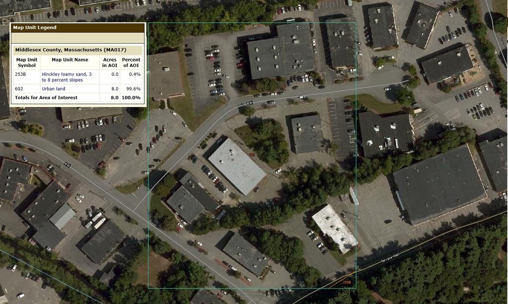
58

59 PROPOSED NYLOPLAST CLEANOUT DMH PROPOSED SYSTEM INSPECTION PORT (TYP)
Inflow Design Flood Control System Plan
 Inflow Design Flood Control System Plan For Compliance with the Coal Combustion Residuals Rule (40 CFR Part 257) Valmont Station - CCR Surface Impoundments Public Service Company of Colorado Denver, Colorado
Mixed-Use Development Site Plan. for. 131 Eliot Street Milton, Massachusetts
 Mixed-Use Development Site Plan for 131 Eliot Street Milton, Massachusetts August 25, 2010 Prepared for: Carrick Realty Trust c/o Jeremiah Connelly, Trustee 1858 Dorchester Avenue Dorchester, MA 02124
Pre-Treatment Bioretention Cells Bioswales IOWA STORMWATER MANAGEMENT MANUAL DECEMBER 16, 2015
 Pre-Treatment Bioretention Cells Bioswales IOWA STORMWATER MANAGEMENT MANUAL DECEMBER 16, 2015 Urban Runoff Background How we got here What Problem?? Provenance of the Problem Unified Sizing Criteria What
Summary of Detention Pond Calculation Canyon Estates American Canyon, California
 July 15, 2015 Bellecci & Associates, Inc Summary of Detention Pond Calculation Canyon Estates American Canyon, California 1. Methodology: Method: Unit Hydrograph Software: Bentley Pond Pack Version 8i
Treatment Volume: Curve Numbers. Composite CN or Not? Treatment Volume: Curve Numbers. Treatment Volume: Calculation. Treatment Volume: Calculation
 Stormwater Engineering Bioretention Design Bill Hunt, PE, Ph.D. Extension Specialist & Assistant Professor NCSU-BAE www.bae.ncsu.edu/stormwater Bioretention Design Six Step Process 1 Determine Volume to
N.J.A.C. 7:8 Stormwater Management Rules - Design and Performance Standards. Nonstructural Strategies Assist with Strategy #2; See Page 3
 9.3 DRY WELLS Dry wells are subsurface stormwater facilities that are used to collect and temporarily store runoff from clean rooftops; runoff is discharged through infiltration into the subsoil. Dry wells
APPENDIX IV. APPROVED METHODS FOR QUANTIFYING HYDROLOGIC CONDITIONS OF CONCERN (NORTH ORANGE COUNTY)
") APPENDIX IV. APPROVED METHODS FOR QUANTIFYING HYDROLOGIC CONDITIONS OF CONCERN (NORTH ORANGE COUNTY) Hydromodification design criteria for the North Orange County permit area are based on the 2- yr, 24-hr
APPENDIX IV. APPROVED METHODS FOR QUANTIFYING HYDROLOGIC CONDITIONS OF CONCERN (NORTH ORANGE COUNTY) Hydromodification design criteria for the North Orange County permit area are based on the 2- yr, 24-hr
Software Applications for Runoff Hydrological Assessment
 Bulletin UASVM Horticulture, 67(2)/2010 Print ISSN 1843-5254; Electronic ISSN 1843-5394 Software Applications for Runoff Hydrological Assessment Severin CAZANESCU 1), Sorin CIMPEANU 1), Oana GUI 2), Dana
Pennsylvania Stormwater Best Management Practices Manual. Chapter 3. Stormwater Management Principles and Recommended Control Guidelines
 Pennsylvania Stormwater Best Management Practices Manual Chapter 3 Stormwater Management Principles and Recommended Control Guidelines 363-0300-002 / December 30, 2006 Chapter 3 Stormwater Management Principles
Initial Run-on and Run-off Control System Plan
 Initial Run-on and Run-off Control System Plan For Compliance with the Coal Combustion Residuals Rule (40 CFR 257.81) Valmont Station - Ash Disposal Facility Public Service Company of Colorado Denver,
Boise City Public Works General Drainage Plan Review Requirements Checklist
 Boise City Public Works General Drainage Plan Review Requirements Checklist Development Name Bldg. Permit # Drainage Reviewer Site Address Initial Review Date ODI Number Designer Company Name Treated Acres
Stormwater Local Design Manual For Houston County, Georgia
 Stormwater Local Design Manual For Houston County, Georgia Adopted November 15, 2005 TABLE OF CONTENTS 1. FORWARD... 1 2. GENERAL LEVEL OF SERVICE STANDARDS... 2 2.1. DETENTION REQUIREMENTS... 2 2.1.1.
MODEL Stormwater Local Design Manual. City of Centerville
 MODEL Stormwater Local Design Manual City of Centerville Adopted December 6, 2005 TABLE OF CONTENTS 1. FORWARD... 1 2. GENERAL LEVEL OF SERVICE STANDARDS... 1 2.1. DETENTION REQUIREMENTS... 1 2.1.1. Discharge
At least 2 feet above the seasonal high water table Overflow path or structure provided
 General Conditions Map of proposed subwatershed to each subbasin, including total area and CN Design Flow or Design Volume to each STF, as appropriate Operation and Maintenance instructions for each STF
City of Redwood City Stormwater Pollution Prevention Program. Drainage Guidelines for Residential Development
 City of Redwood City Stormwater Pollution Prevention Program Drainage Guidelines for Residential Development General Requirements A. Plot & Finished Grading Plan must be submitted with Building Permit
SUBSURFACE INFILTRATION SYSTEM DESCRIPTION. Alternative Names: Sump, Drywell, Infiltration Trench, Infiltration Galleries, Leach Fields
 4.1-d SUBSURFACE INFILTRATION SYSTEM Alternative Names: Sump, Drywell, Infiltration Trench, Infiltration Galleries, Leach Fields BMP DESIGN APPROACH Pollutant Source Control Hydrologic Source Control Stormwater
CHAPTER 3 STORMWATER HYDROLOGY. Table of Contents SECTION 3.1 METHODS FOR ESTIMATING STORMWATER RUNOFF
 CHAPTER 3 STORMWATER HYDROLOGY Table of Contents SECTION 3.1 METHODS FOR ESTIMATING STORMWATER RUNOFF 3.1.1 Introduction to Hydrologic Methods...3.1-1 3.1.2 Symbols and Definitions...3.1-3 3.1.3 Rainfall
E. STORMWATER MANAGEMENT
 E. STORMWATER MANAGEMENT 1. Existing Conditions The Project Site is located within the Lower Hudson Watershed. According to the New York State Department of Environmental Conservation (NYSDEC), Lower Hudson
BMP #: Water Quality Inserts
 Structural BMP Criteria BMP #: Water Quality Inserts Catch basin inserts are commercially available (manufactured) devices and are generally configured to remove one or more of the following contaminants:
NEW CASTLE CONSERVATION DISTRICT. through. (Name of Municipality) PLAN REVIEW APPLICATION DRAINAGE, STORMWATER MANAGEMENT, EROSION & SEDIMENT CONTROL
 PLAN REVIEW APPLICATION DRAINAGE, STORMWATER MANAGEMENT, EROSION & SEDIMENT CONTROL") NEW CASTLE CONSERVATION DISTRICT through (Name of Municipality) PLAN REVIEW APPLICATION DRAINAGE, STORMWATER MANAGEMENT, EROSION & SEDIMENT CONTROL Office use only: Received by Municipality: Received by
NEW CASTLE CONSERVATION DISTRICT through (Name of Municipality) PLAN REVIEW APPLICATION DRAINAGE, STORMWATER MANAGEMENT, EROSION & SEDIMENT CONTROL Office use only: Received by Municipality: Received by
Chatham Park Stormwater Manual
 Chatham Park Stormwater Manual Table of Contents A. Introduction... 2 B. Calculation Methods... 2 C. BMP Design Standards... 3 D. Compliance Points... 3 E. Critical Environmental Resources... 3 F. Submittal
Chapter 6. Hydrology. 6.0 Introduction. 6.1 Design Rainfall
 6.0 Introduction This chapter summarizes methodology for determining rainfall and runoff information for the design of stormwater management facilities in the City. The methodology is based on the procedures
COON CREEK WATERSHED DISTRICT PERMIT REVIEW. Spring Lake Park Schools Westwood Middle School st Avenue NE, Spring Lake Park, MN 55432
 PAN 16-112, Westwood Middle School, Page 1 of 6 COON CREEK WATERSHED DISTRICT PERMIT REVIEW MEETING DATE: August 22, 2016 AGENDA NUMBER: 10 FILE NUMBER: 16-112 ITEM: Westwood Middle School RECOMMENDATION:
Infiltration Stormwater Control Measures. Andrew R. Anderson, M.S., E.I.T. Extension Associate Engineer
 Infiltration Stormwater Control Measures Andrew R. Anderson, M.S., E.I.T. Extension Associate Engineer Overview of Presentation NCDENR Infiltration Devices Infiltration and the SHWT Innovative infiltration
Urban Drainage Introduction. A.Ramachandra Rao. C.B. Burke. T.T. Burke, Jr.
 32 Urban Drainage A.Ramachandra Rao Purdue University C.B. Burke Christopher B. Burke Engineering, Ltd. T.T. Burke, Jr. Christopher B. Burke Engineering, Ltd. 32.1 Introduction 32.2 The Rational Method
16.0 Water Quality Management Criteria for Developed Land
 October 2003, Revised February 2005 Criteria for Developed Land Page 1 16.1 Introduction 16.0 Water Quality Management Criteria for Developed Land Stormwater quality control is an integral part of any
Review of State and Federal Stormwater Regulations November 2007
 Review of State and Federal Stormwater Regulations November 2007 By: James T. Spaulding, PE, CPESC Joseph M. Ducharme, Jr., PE TTG ENVIRONMENTAL CONSULTANTS, LLC 27 LOCKE ROAD, CONCORD, NH 03301-5301 TELEPHONE:
STORMWATER RUNOFF AND WATER QUALITY IMPACT REVIEW
 SUBCHAPTER 8 STORMWATER RUNOFF AND WATER QUALITY IMPACT REVIEW 7:45-8.1 Purpose and scope of review Except for those projects expressly exempted by this chapter or waived by the Commission, the Commission
Municipal Stormwater Ordinances Summary Table
 APPENDIX F Municipal Ordinances Summary Table Municipality Abington Bryn Athyn Borough Hatboro Borough Ordinance, SALDO Runoff equals pre post Erosion Sediment Control Water Quality Requirements Any which
Green Infrastructure BMPs. Hydrologic Performance Small Storms
 Green Infrastructure BMPs Hydrologic Performance Small Storms Clay Emerson, Ph.D. Princeton Hydro Robert G. Traver, Ph.D., PE Department of Civil and Environmental Engineering Villanova University Director,
Runoff Hydrographs. The Unit Hydrograph Approach
 Runoff Hydrographs The Unit Hydrograph Approach Announcements HW#6 assigned Storm Water Hydrographs Graphically represent runoff rates vs. time Peak runoff rates Volume of runoff Measured hydrographs are
CHECKLIST FOR STREETS, INLETS, AND STORM SEWER DESIGN
 CHECKLIST FOR STREETS, INLETS, I. STREET CLASSIFICATION AND DESIGN CRITERIA A. Determine drainage classification for the roadway section using Table 7-1 or Table 7-2. B. Determine the allowable flow depth
EXAMPLE Stormwater Management Plans w/ CSS BMP Sizing Calculator (v2.1)
") 525 Golden Gate Avenue, 11th Floor San Francisco, CA 94102 EXAMPLE Stormwater Management Plans w/ CSS BMP Sizing Calculator (v2.1) The following example Stormwater Management Plans (SMPs) are provided
525 Golden Gate Avenue, 11th Floor San Francisco, CA 94102 EXAMPLE Stormwater Management Plans w/ CSS BMP Sizing Calculator (v2.1) The following example Stormwater Management Plans (SMPs) are provided
Hydrologic Impacts of Exceeding Zoning Ordinances. on Impervious Lot Coverage: TR-55 modeling of three. Zoning Districts in Shippensburg Borough
 Hydrologic Impacts of Exceeding Zoning Ordinances on Impervious Lot Coverage: TR-55 modeling of three Zoning Districts in Shippensburg Borough Practical Exam-Revisions Kristina Everetts November 19, 2013
BMP #: Infiltration Basin
 Structural BMP Criteria BMP #: Infiltration Basin An Infiltration Basin is a shallow impoundment that stores and infiltrates runoff over a level, subtle, uncompacted, (preferably undisturbed area) with
Appendix B. Storm Drain System Data
 MENIFEE VALLEY CAMPUS MASTER PLAN FINAL EIR MT. SAN JACINTO COMMUNITY COLLEGE DISTRICT Appendix Appendix B. Storm Drain System Data June 2017 MENIFEE VALLEY CAMPUS MASTER PLAN FINAL EIR MT. SAN JACINTO
Table of Contents. Overview... 1
 Chapter 3 Chapter 3 Table of Contents Overview... 1 Rainfall... 2 3-2-1 Rainfall Depths and Intensities... 2 3-2-2 Design Storm Distribution for Colorado Urban Hydrograph Procedure (CUHP)... 5 3-2-3 Temporal
Detention Pond Design and Analysis. CE 378 Water Resources Engineering. Contents
 R. Pitt April 12, 2004 Detention Pond Design and Analysis CE 378 Water Resources Engineering Contents Introduction...1 Expected Detention Pond Performance...2 Potential Detention Pond Problems...3 Wet
SAN GORGONIO PASS CAMPUS - PHASE I
 SAN GORGONIO PASS CAMPUS - PHASE I Banning, CA DRAINAGE STUDY June 16, 2010 Reference 106-195 PREPARED BY: Encompass Associates, Inc. 5699 Cousins Place Rancho Cucamonga, CA 91737 909-684-0093 Fax-909-586-6979
DIVISION 5 STORM DRAINAGE CRITERIA
 DIVISION 5 STORM DRAINAGE CRITERIA Section 5.01 GENERAL The following storm drainage design criteria shall apply to all storm drainage designs in the City. Additional design criteria are specified in the
iswm TM Technical Manual Hydrology:
 : 1.0 2.0 Downstream Assessment 3.0 Streambank Protection 4.0 Water Balance 5.0 Rainfall Tables 6.0 Hydrologic Soils Data Table of Contents 1.0... HO-1 1.1 Estimating Runoff... HO-1 1.1.1 Introduction
Storm Sewer Design. Bob Pitt University of Alabama and Shirley Clark Penn State Harrisburg
 Storm Sewer Design Bob Pitt University of Alabama and Shirley Clark Penn State Harrisburg Major floods are dramatic and water flow routes must be recognized when minor drainage systems fail. These types
CACHE VALLEY STORM WATER DESIGN STANDARDS. As Amended by Logan City November 2010
 CACHE VALLEY STORM WATER DESIGN STANDARDS As Amended by Logan City November 2010 Updated November 2010 Table of Contents A. Definitions... 3 B. Design Requirements... 5 1. Storm Event... 5 2. Allowable
TECHNICAL MEMORANDUM. SUBJECT: Determination of watershed historic peak flow rates as the basis for detention basin design
 TECHNICAL MEMORANDUM FROM: Ken MacKenzie and Ryan Taylor SUBJECT: Determination of watershed historic peak flow rates as the basis for detention basin design DATE: June 7, 2012 The purpose of this memorandum
Pennsylvania Stormwater Best Management Practices Manual. Section 3 Stormwater Management Principles, Goals, and a Management Model
 Pennsylvania Stormwater Best Management Practices Manual DRAFT - JANUARY 2005 Section 3 Stormwater Management Principles, Goals, and a Management Model This page intentionally left blank. Section 3 Stormwater
Jamestown Public Schools Bush Elementary Addition and Alterations
 ADDENDUM TO THE STORMWATER POLLUTION PREVENTION PLAN For the Jamestown Public Schools Bush Elementary Addition and Alterations Jamestown, New York Chautauqua County February, 2014 Clark Patterson Lee DESIGN
Section 600 Runoff Table of Contents
 Section 600 Runoff Table of Contents 601 INTRODUCTION...600-1 602 RATIONAL METHOD...600-1 602.1 Rational Method Formula...600-2 602.2 Time of Concentration...600-2 602.3 Intensity...600-4 602.4 Runoff
ROLES AND RESPONSIBILITIES Small Pond Approval. SWM MD-378 Pond Checklist Training 10/17/07. Exemptions EMBANKMENT HEIGHT. Height of Dam Weir Wall
 SWM MD-378 Pond Checklist Training 10/17/07 Ken Wolfe Warren Johnson USDA, NRCS Frederick, Maryland ROLES AND RESPONSIBILITIES Small Pond Approval MDE, WMA, Dam Safety Division Authority (COMAR 26.17.04.03)
6.0 Runoff. 6.1 Introduction. 6.2 Flood Control Design Runoff
 October 2003, Revised February 2005 Chapter 6.0, Runoff Page 1 6.1 Introduction 6.0 Runoff The timing, peak rates of discharge, and volume of stormwater runoff are the primary considerations in the design
Standards for Soil Erosion and Sediment Control in New Jersey May 2012 STANDARD FOR SLOPE PROTECTION STRUCTURES. Definition
 STANDARD FOR SLOPE PROTECTION STRUCTURES Definition Structures to safely conduct surface runoff from the top of a slope to the bottom of the slope. Purpose The purpose of this practice is to convey storm
6 STOREY CONDOMINIUM 7480 DERRY ROAD WEST, MILTON
 6 STOREY CONDOMINIUM 7480 DERRY ROAD WEST, MILTON STORM WATER MANAGEMENT DESIGN BRIEF NEW DEVELOPMENT DRAINAGE SYSTEM REV 0 August 29, 2017 PREPARED BY: HALLEX PROJECT #170532 HALLEX NIAGARA HALLEX HAMILTON
DURMM: THE DELAWARE URBAN RUNOFF MANAGEMENT MODEL
 DURMM: THE DELAWARE URBAN RUNOFF MANAGEMENT MODEL A USERS MANUAL FOR DESIGNING GREEN TECHNOLOGY BMPs TO MINIMIZE STORMWATER IMPACTS FROM LAND DEVELOPMENT William C. Lucas INTEGRATED LAND MANAGEMENT, INC.
Storm Water Management Standards
 Storm Water Management Standards The City of Roseville has developed specific requirements that apply to development and redevelopment projects. These standards are intended to help achieve the water resource
PERVIOUS PAVEMENT. Alternative Names: Permeable Pavement, Porous Concrete, Porous Pavers
 4.1-a PERVIOUS PAVEMENT Alternative Names: Permeable Pavement, Porous Concrete, Porous Pavers DESCRIPTION Pervious pavement is any system comprised of a load bearing surface that allows for movement of
Chapter 7. Street Drainage. 7.0 Introduction. 7.1 Function of Streets in the Drainage System. 7.2 Street Classification
 7. Introduction This chapter summarizes methods to evaluate runoff conveyance in various street cross sections and curb types in the Town of Castle Rock and identifies acceptable upper limits of street
Infiltration Guidelines
 Appendix E Infiltration Guidelines As a stormwater management method, infiltration means retaining or detaining water within soils to reduce runoff. Infiltration can be a cost-effective method to manage
Constructed Wetland Use in Nonpoint Source Control
 Constructed Wetland Use in Nonpoint Source Control Description Constructed wetlands are excavated basins with irregular perimeters and undulating bottom contours into which wetland vegetation is purposely
ENGINEERED SOLUTIONS. Terre Arch Concrete Detention/Infiltration. Solutions Guide
 ENGINEERED SOLUTIONS Terre Arch Concrete Detention/Infiltration Solutions Guide Stormwater Solutions from Contech Selecting the Right Stormwater Solution Just Got Easier... It s simple to choose the right
APPENDIX C INLETS. The application and types of storm drainage inlets are presented in detail in this Appendix.
 Storm Drainage 13-C-1 APPENDIX C INLETS 1.0 Introduction The application and types of storm drainage inlets are presented in detail in this Appendix. 2.0 Inlet Locations Inlets are required at locations
APPENDIX A: STORMWATER HYDROLOGY
 APPENDIX A: STORMWATER HYDROLOGY In low impact development (LID), the objective of stormwater control measures (SCMs) is to mimic or replicate the hydrologic function of a natural system. This approach
Plan Name Plan No. Submitting Firm Contact Engineer. Review Date ESI Team ENGINEERS AND SURVEYORS INSTITUTE PEER REVIEW CHECKLIST CITY OF ALEXANDRIA
 EROSION AND SEDIMENT CONTROL CHECKLIST (E&S) VIRGINIA EROSION AND SEDIMENT CONTROL HANDBOOK (1 of 2) Item # Description OK NO N/A 1 Limits of clearing and grading match on all appropriate sheets 2 Construction
CRITERIA FOR STORMWATER DESIGN
 ..CHAPTER.. CRITERIA FOR STORMWATER DESIGN 2.1 Integrated Site Design Approach 2.1.1 Introduction This chapter represents the requirements, policies and other guidance for stormwater management design
Gwinnett County Stormwater System Assessment Program
 Gwinnett County Stormwater System Assessment Program Jonathan Semerjian, PE Dept. of Water Resources Stormwater Management Sam Fleming, PE Dewberry Presentation Overview Project Background Drivers Enhanced
Runoff Processes. Daene C. McKinney
 CE 374 K Hydrology Runoff Processes Daene C. McKinney Watershed Watershed Area draining to a stream Streamflow generated by water entering surface channels Affected by Physical, vegetative, and climatic
CEE3430 Engineering Hydrology
 CEE3430 Engineering Hydrology Practice Exam (There are multiple practice questions here A 110 min test will likely not have more than four questions) 1. Water Balance Write the water balance as Δ Where
APPENDIX G HYDRAULIC GRADE LINE
 Storm Drainage 13-G-1 APPENDIX G HYDRAULIC GRADE LINE 1.0 Introduction The hydraulic grade line is used to aid the designer in determining the acceptability of a proposed or evaluation of an existing storm
Project Name: Add a unique name that appropriately identifies the submission
 PTAPP Online Municipal Tracking Tool Instructions Project Name: Add a unique name that appropriately identifies the submission Municipal Project: Check this box if the project is part of municipal efforts
BRADLEY UNIVERSITY. The Performance and Sustainability of Permeable Pavement Progress Report on the Work Performed Under IAPA Scholarship
 BRADLEY UNIVERSITY The Performance and Sustainability of Permeable Pavement Progress Report on the Work Performed Under IAPA Scholarship Anne Riemann 12/19/2016 1 INTRODUCTION Permeable pavement is an
Article 20: Erosion Control and Stormwater Management
 Article 20: Erosion Control and Stormwater Management Section 360: Purpose, Scope of Authority, Performance Guarantee and Approvals A. Purpose. The purpose of this document is to set forth minimum requirements
Erosion & Sedimentation Control Policy
 Issue Date 10/22/2010 Page 1 of 8 Erosion & Sedimentation Control Policy Introduction: Soil erosion is the removal of soil by water, wind, ice or gravity and sediment deposition occurs when the rate of
Chapter 3 Calculating the WQCV and Volume Reduction
 Contents 1.0 Introduction... 1 2.0 Hydrologic Basis of the WQCV... 1 2.1 Development of the WQCV... 1 2.2 Optimizing the Capture Volume... 3 2.3 Attenuation of the WQCV (BMP Drain Time)... 4 2.4 Excess
Constructed Wetland Channel T-9
 Description A constructed wetland channel is a conveyance BMP that is built, in part, to enhance stormwater quality. Constructed wetland channels use dense vegetation to slow down runoff and allow time
Stormwater Management Standards
 Stormwater Management Standards In 1996, the Massachusetts Department of Environmental Protection (the Department or MassDEP ) issued the Stormwater Policy that established Stormwater Management Standards
Table of Contents. 5-5 Release Rates Year Allowable Release Rate WQCV Release Rate EURV Release Rate...
 Chapter 5 Table of Contents 5-1 Introduction... 1 5-1-1 Stormwater Quality Considerations... 1 5-1-2 Stormwater Volume Considerations... 2 5-1-3 Downstream Impacts... 2 5-2 Requirements... 2 5-2-1 General
Simple Method for Estimating Phosphorus Export
 Appendix L Simple Method for Estimating Phosphorus Export 1. The Simple Method The Simple Method is a technique used for estimating storm pollutant export delivered from urban development sites. The method
STORMWATER RUN-ON AND RUN-OFF CONTROL PLAN ENTERGY ARKANSAS, INC. INDEPENDENCE PLANT CLASS 3N CCR LANDFILL
 STORMWATER RUN-ON AND RUN-OFF CONTROL PLAN ENTERGY ARKANSAS, INC. INDEPENDENCE PLANT CLASS 3N CCR LANDFILL PERMIT NO. 0200-S3N-R2 AFIN: 32-00042 OCTOBER 12, 2016 STORMWATER RUN-ON AND RUN-OFF CONTROL PLAN
Lyon Creek Cedar Way Stormwater Detention Dam Operation and Maintenance Manual
 Lyon Creek Cedar Way Stormwater Detention Dam Operation and Maintenance Manual Prepared by: Mike Shaw Stormwater Program Manager City of Mountlake Terrace January 2010 Section I General Information This
MC-3500 and MC-4500 Design Manual
 MC-3500 / MC-4500 MC-3500 and MC-4500 Design Manual StormTech Chamber Systems for Stormwater Management Table of Contents 1.0 Product Information...2 2.0 Foundations for Chambers...8 3.0 Required Materials/Row
Rhode Island Stormwater Design and Installations Standards Manual
 Rhode Island Stormwater Design and Installations Standards Manual Public Workshop Required Management Volume Calculations and Redevelopment Considerations March 22, 2011 Presentation Outline Recap of How
City of Oakland. Public Works Agency Standards STORM DRAINAGE DESIGN GUIDELINES. Engineering Design & ROW Management Division
 City of Oakland PUBLIC WORKS AGENCY 250 FRANK H. OGAWA PLAZA 4 TH FLOOR OAKLAND, CALIFORNIA 94612 (510) 238-3437 FAX (510) 238-7227 TTD (510) 238-3254 Public Works Agency Standards STORM DRAINAGE DESIGN
Run-On and Run-Off Control System Plan Neal North Energy Center Monofill
 Run-On and Run-Off Control System Plan Neal North Energy Center Monofill MidAmerican Energy Company, Neal North Energy Center Coal Combustion Residual Rule Compliance October 10, 2016 Run-On and Run-Off
LAWRENCE, KANSAS STORMWATER MANAGEMENT CRITERIA
 LAWRENCE, KANSAS STORMWATER MANAGEMENT CRITERIA FEBRUARY 1996 CITY OF LAWRENCE, KANSAS STORMWATER MANAGEMENT CRITERIA TABLE OF CONTENTS Pg 1.0 GENERAL 1.1 Introduction... 1 1.2 Applicability... 1 1.3 General
Stormwater Volume and Treatment Methods Simplifying the Numbers. IAFSM March 10, Presented by: Tom Powers P.E., CFM, LEED AP, CPESC
 Stormwater Volume and Treatment Methods Simplifying the Numbers IAFSM March 10, 2011 Presented by: Tom Powers P.E., CFM, LEED AP, CPESC Introduction GOALS: Improve understanding of Rate and Volume (Quantity)
Effect of the Underlying Groundwater System on the Rate of Infiltration of Stormwater Infiltration Structures.
 Effect of the Underlying Groundwater System on the Rate of Infiltration of Stormwater Infiltration Structures. Presented at: Storm Water Infiltration & Groundwater Recharge A Conference on Reducing Runoff
StormwaterWise Landscapes: Pervious Surfaces Specifications
 StormwaterWise Landscapes: Pervious Surfaces Specifications Purpose & Benefits Stormwater runoff reduction High pollutant removal Control localized drainage problems Attractive alternative for walkways
Extended Detention Basin (EDB) Sedimentation Facility
 Sedimentation Facility") Extended Detention Basin (EDB) Sedimentation Facility Description An extended detention basin (EDB) is a sedimentation basin designed to totally drain dry sometime after stormwater runoff ends. It is an
Extended Detention Basin (EDB) Sedimentation Facility Description An extended detention basin (EDB) is a sedimentation basin designed to totally drain dry sometime after stormwater runoff ends. It is an
Richland County Department of Public Works Engineering (Land Development) Division
 Division") Richland County Department of Public Works Engineering (Land Development) Division Commercial Projects What is a Commercial Project? Projects that are not related to residential single family homes and/or
Richland County Department of Public Works Engineering (Land Development) Division Commercial Projects What is a Commercial Project? Projects that are not related to residential single family homes and/or
CITY OF ASTORIA PUBLIC WORKS ENGINEERING DIVISION ENGINEERING DESIGN STANDARDS FOR IN-FILL DEVELOPMENT
 CITY OF ASTORIA PUBLIC WORKS ENGINEERING DIVISION ENGINEERING DESIGN STANDARDS FOR IN-FILL DEVELOPMENT Adopted by City Council: May 21, 2007 X:\General Eng\DESIGN STANDARDS\Engineering Design Standards
UMD Storm Water Program Construction Requirements. Greg Archer, MBA Environmental Compliance Specialist
 UMD Storm Water Program Construction Requirements Greg Archer, MBA Environmental Compliance Specialist Phase 2 Regulatory Overview Dec. 1999 EPA issues Phase 2 Federal Register Municipalities (MS4) from
110 STORMWATER MANAGEMENT AND COLLECTION SYSTEMS
 110 STORMWATER MANAGEMENT AND COLLECTION SYSTEMS 110.01 DEFINITIONS 110.01.01 Detention structure. A permanent structure for the temporary storage of stormwater runoff that is designed so as not to create
Culvert Sizing procedures for the 100-Year Peak Flow
 CULVERT SIZING PROCEDURES FOR THE 100-YEAR PEAK FLOW 343 APPENDIX A: Culvert Sizing procedures for the 100-Year Peak Flow A. INTRODUCTION Several methods have been developed for estimating the peak flood
Sizing Criteria Worksheets and Examples
 Appendix B Sizing Criteria Worksheets and Examples This Appendix provides sizing criteria worksheets and examples to illustrate the correct procedures for determining the water quality design flow and
1. Stream Network. The most common approach to quantitatively describing stream networks was postulated by Strahler (1952).
.") 1. Stream Network The most common approach to quantitatively describing stream networks was postulated by Strahler (1952). First Order Streams streams with no tributaries. Second Order Streams begin at
1. Stream Network The most common approach to quantitatively describing stream networks was postulated by Strahler (1952). First Order Streams streams with no tributaries. Second Order Streams begin at
2C-12 Detention Basin Outlet Structures
 Iowa Stormwater Management Manual 2C-12 2C-12 Detention Basin Outlet Structures A. Introduction The methods described in Section 2C-9 are used to estimate the volume of the detention storage. The second
CLARK COUNTY REGIONAL FLOOD CONTROL DISTRICT HYDROLOGIC CRITERIA AND DRAINAGE DESIGN MANUAL
 CLARK COUNTY REGIONAL FLOOD CONTROL DISTRICT HYDROLOGIC CRITERIA AND DRAINAGE DESIGN MANUAL SECTION 600 STORM RUNOFF TABLE OF CONTENTS 601 INTRODUCTION 603 601.1 - Basin Characteristics 603 602 TIME OF
Extended Detention Basin Maintenance Plan for [[== Insert Project Name ==]]
![Extended Detention Basin Maintenance Plan for [[== Insert Project Name ==]]](/thumbs/72/68075589.jpg "Extended Detention Basin Maintenance Plan for [[== Insert Project Name ==]]") Extended Detention Basin Plan for [[== Insert Project Name ==]] [[== Insert Date =]] Project Address and Cross Streets Assessor s Parcel No.: Property Owner: Phone No.: Designated Contact: Phone No.: Extended
Extended Detention Basin Plan for [[== Insert Project Name ==]] [[== Insert Date =]] Project Address and Cross Streets Assessor s Parcel No.: Property Owner: Phone No.: Designated Contact: Phone No.: Extended
Red Barn R.V. and Boat Storage Weld County, Colorado. Final Drainage Report
 Red Barn R.V. and Boat Storage Weld County, Colorado Final Drainage Report Prepared for Kevin Moore Project No. 1318-001 February 27, 2017 Prepared By: KETTERLING, BUTHERUS AND NORTON ENGINEERS, LLC. 820
Section SNOW DISPOSAL SITE DESIGN CRITERIA
 Section 2.150 SNOW DISPOSAL SITE DESIGN CRITERIA 2.150 A. Introduction Snow disposal sites provide storage areas for snowfall that exceeds the storage capacity of street rights-of-way and other public
Estimated Construction Cost: $30,000-$110,000
 SITE 11 BMP retrofits at Smith Middle School Index Sheet No.: 16 Raw Data Name: IJ 34 Estimated Construction Cost: $30,000-$110,000 Page 73 CAMDEN LN CLAYMORE RD BURNS PL WHITMORE CIR S HAWICK CT ROGERS
Stormwater Quality Extended Detention Basin Operation and Maintenance (O&M) Manual. for: Located at: Prepared for: Prepared by:
 Manual. for: Located at: Prepared for: Prepared by:") Stormwater Quality Extended Detention Basin Operation and Maintenance (O&M) Manual for: Insert Development Name Located at: Insert Address Prepared for: Insert Property Owner Name, Address, and Phone Number
Stormwater Quality Extended Detention Basin Operation and Maintenance (O&M) Manual for: Insert Development Name Located at: Insert Address Prepared for: Insert Property Owner Name, Address, and Phone Number