Run-On and Run-Off Control System Plan Neal North Energy Center Monofill
|
|
|
- Kenneth Stanley
- 6 years ago
- Views:
Transcription


1 Run-On and Run-Off Control System Plan Neal North Energy Center Monofill MidAmerican Energy Company, Neal North Energy Center Coal Combustion Residual Rule Compliance October 10, 2016
2 Run-On and Run-Off Control System Plan Neal North Energy Center Monofill Prepared for MidAmerican Energy Company, Neal North Energy Center Coal Combustion Residual Rule Compliance Sergeant Bluff, Iowa October 10, 2016 Prepared by Burns & McDonnell Engineering Company, Inc. Kansas City, Missouri COPYRIGHT 2016 BURNS & McDONNELL ENGINEERING COMPANY, INC.

3 INDEX AND CERTIFICATION MidAmerican Energy Company, Neal North Energy Center Run-On and Run-Off Control System Plan Neal North Energy Center Monofill Chapter Number Chapter Title Report Index Number of Pages 1.0 Introduction Site Hydrology Stormwater Run-On and Run-Off Control System Stormwater Best Management Practices Periodic Assessment and Ammendment Revisions and Updates 1 Appendix A Existing Permit Plans, Attachment 23 (Calculations for Run- On/Run-Off Controls) 25 Appendix B Verification Calculations 7 Certification I hereby certify, as a Professional Engineer in the State of Iowa, that the information in this document was assembled under my direct personal charge. This report is not intended or represented to be suitable for reuse by the MidAmerican Energy Company, Neal North Energy Center or others without specific verification or adaptation by the Engineer. Kira E. Wylam, P.E. Date: 10/10/2016 Kira E. Wylam License Number My license renewal date is December 31, 2016 Pages or sheets covered by this seal: As noted above.
4 Run-On and Run-Off Control Plan Neal North Energy Center Monofill Table of Contents TABLE OF CONTENTS Page No. 1.0 INTRODUCTION Existing Design Document Review Permit Design Calculation - Methodology Plan Requirements SITE HYDROLOGY Site Characteristics Design Storms STORMWATER CONTROL SYSTEMS Run-On Analysis Leachate Collection System Existing Conditions Run-Off Analysis Post-Closure Conditions Run-Off Analysis Intermediate Swales Inner Perimeter Channel Channel Compliance Summary STORMWATER BEST MANAGEMENT PRACTICES PERIODIC ASSESSMENT AND AMMENDMENT REVISIONS AND UPDATES REFERENCES EXISTING PERMIT DOCUMENT PLANS & APPENDIX 4 (DESIGN DRAWINGS FOR POST CLOSURE RUN-OFF CONTROLS) - ACTIVE MONOFILL PORTION CALCULATIONS MidAmerican Energy Company TOC-1 Burns & McDonnell
5 Run-On and Run-Off Control Plan Neal North Energy Center Monofill Table of Contents LIST OF FIGURES Page No. Figure 2-1. Neal North Monofill Extent Figure 2-2. Hydrologic Soil Groups Figure 2-3. Elevations Surrounding Neal North Monofill Figure 2-4. Point Precipitation Location Figure 2-5. NOAA Point Precipitation Frequency Estimates Figure 3-1. Neal North Monofill Drainage Areas Figure 3-2. Neal North - FEMA Floodplain Boundaries Figure 3-3. Neal North Monofill Drainage Areas MidAmerican Energy Company TOC-2 Burns & McDonnell
6 Run-On and Run-Off Control Plan Neal North Energy Center Monofill List of Abbreviations LIST OF ABBREVIATIONS Abbreviation BMP CCR CFR EPA HSG IAC IDNR MEC NOAA RCRA SCS Term/Phrase/Name Best Management Practice Coal Combustion Residual Code of Federal Regulations Environmental Protection Agency Hydrologic Soil Group Iowa Administrative Code Iowa Department of Natural Resources MidAmerican Energy Company National Oceanic and Atmospheric Administration Resource Conservation and Recovery Act Soil Conservation Service TR-55 Technical Release 55 TSS U.S.C. Total Suspended Solids United States Code MidAmerican Energy Company i Burns & McDonnell
7 Run-On and Run-Off Control Plan Neal North Energy Center Monofill Introduction 1.0 INTRODUCTION On April 17, 2015, the Environmental Protection Agency (EPA) issued the final version of the federal Coal Combustion Residual Rule (CCR Rule) to regulate the disposal of coal combustion residual (CCR) materials generated at coal-fired units. The rule is administered as part of the Resource Conservation and Recovery Act [RCRA, 42 United States Code (U.S.C.) 6901 et seq.], using the Subtitle D approach. MidAmerican Energy Company (MEC) is subject to the CCR Rule and as such must develop a Run-On and Run-Off Control System Plan per 40 Code of Federal Regulations (CFR) This report provides and certifies the Run-On and Run-Off Control System Plan for the Neal North Energy Center Landfill located near Sergeant Bluff, Iowa. Run-on controls for the Neal North Energy Center Landfill were designed by MWH, Inc. as part of past permit applications to the State of Iowa. Post-closure run-off controls for the Neal North Energy Center Landfill were designed by MWH, Inc. as part of past permit applications to the State of Iowa. The Run- On and Post-closure Run-Off Control System Plans provided herein are based on review and assessment of those certified drawings and a current analysis of existing conditions based on recently obtained elevation data of the active portion of the landfill. The most recent control plan was developed in 2007 and approved in The applicable section of the 2007 Permit Application, Appendix 2, prepared by MWH, Inc. is included as Appendix A of this document. 1.1 Existing Design Document Review The CCR Rule requires the run-off volume from a 24-hour, 25-year storm from the active portion of the landfill be collected and controlled by run-off control measures, and that a run-on control system be in place. The EPA defines run-on as any rainwater, leachate, or other liquid that drains over land onto any part of a CCR landfill or lateral expansion of a CCR landfill. The EPA defines run-off as any rainwater, leachate, or other liquid that drains over land from any part of a CCR landfill or lateral expansion of a CCR landfill. The drawings depicted in Appendix 2 of the 2007 Permit Application document support compliance with the CCR Rule run-off control system plan requirements, post-closure Permit Design Calculation - Methodology The design calculations in Appendix A for post-closure peak flow in the intermediate swales and flume pipes were performed using generally accepted engineering practices. Due to the 2015 CCR rule requirements, new investigations and calculations were performed for stormwater run-on and run-off of the current conditions of the Neal North Monofill. These calculations MidAmerican Energy Company 1-1 Burns & McDonnell
8 Run-On and Run-Off Control Plan Neal North Energy Center Monofill Introduction were also performed for current conditions using generally accepted engineering practices. The NRCS TR-55 methodology was used, as implemented in the U.S. Army Corps of Engineers HEC-HMS model (USACE, 2010). 1.2 Plan Requirements The Run-On and Run-Off Control System Plans under the CCR Rule must contain the following per (c): Documentation of how the run-on and run-off control systems have been designed and constructed to meet the following requirements: o A run-on control system to prevent flow onto the active portion of the CCR unit during peak discharge from a 24-hour, 25-year storm; and o A run-off control system from the active portion of the CCR unit to collect and control at least the water volume resulting from a 24-hour, 25-year storm. Run-off from the active portion of the CCR unit must be handled in accordance with the surface water requirements under Supporting engineering calculations for the plan. Certification by a qualified professional engineer. The seal certifies that the initial run-on and run-off control system plan provided herein meets the requirements of 40 Code of Federal Regulations There are two relevant parts of the Iowa Administrative Code (IAC) that the CCR unit must adhere to, which are listed below: Chapter 103 for Sanitary Landfills: Coal Combustion Residue (3) c. Surface run-off must be diverted from all active or closed areas, both during the active life of the facility and during the postclosure period. Chapter 113 for Sanitary Landfills for Municipal Solid Waste (8) a. Owners or operators of all MSWLF units must design, construct, and maintain the following: (1) A run-on control system to prevent flow onto the active portion of the landfill during the peak discharge from a 25-year storm; (2) A run-off control system from the active portion of the landfill to collect and control at least the water volume resulting from a 24-hour, 25-year storm. b. Run-off from the active portion of the MSWLF unit must be handled in accordance with paragraph (1) a. MidAmerican Energy Company 1-2 Burns & McDonnell
9 Run-On and Run-Off Control Plan Neal North Energy Center Monofill Site Hydrology 2.0 SITE HYDROLOGY The run-on and run-off control features are to be designed to collect and control the run-off from the 25-year, 24-hour storm event. The methods of determination of the peak flow rates and run-off volumes are based on the Soil Conservation Service (SCS) run-off curve number method (USDA, 1986), to calculate losses, the Rational Method and the TR-55 methodology via HEC-HMS as outlined in the Iowa Stormwater Manual (IDNR, 2009); Manning s equation to calculate channel depths. This section provides an analysis of run-on control, an analysis of existing run-off controls, and a review of the calculations of the run-off controls during the post-closure phase of the Monofill lifespan, which are included in Appendix A. 2.1 Site Characteristics The Monofill encompasses approximately 83 acres in two adjacent parcels and is located approximately 5 miles south of the Sioux City Municipal Airport and approximately 3,500 feet southeast of the Neal North generating station near the east bank of the Missouri River. The active portion of the Monofill is approximately 15 acres. The Monofill is located within Section 30, T87N, R47W in Woodbury County, Iowa. The Monofill site is composed of existing and potential future fill areas. The site is located on the relatively level alluvial plain of the Missouri River. The active fill area, and other landfill cells in their post-closure phase, are the dominant topographic features. Surface drainage ultimately enters the Missouri River either by overland or channelized flow. Run-off is curtailed in many areas because level topography and shallow permeable soils promote significant infiltration to shallow groundwater. Discussion of the surface topographic features and run-off routes from the fill area follows. The extent of the active fill area is shown in Figure 2-1. The site soils belong to hydrologic soil groups (HSG) A, B, C/D, and D (see Figure 2-2). Group A is characterized by having low run-off potential and a high infiltration rate, even when fully wetted. Group B is characterized by having soils with a moderate infiltration rate when thoroughly wetted, consisting chiefly of moderately-deep to deep, moderately-well to well-drained soils, with moderately-fine to moderately-coarse texture. Group C is characterized by having soils with low infiltration rates when thoroughly wetted and consist chiefly of soils with a layer that impedes downward movement of water. Group D is characterized by having soils with a high run-off potential and a very slow infiltration rate when thoroughly wetted, consisting chiefly of clay soils with a high swelling potential, soils with a permanent high water table, soils with a clay pan or clay layer at or near the surface, and shallow soils over nearly impervious material. The C/D group is a mixture of Group C and Group D soils. The hydrologic soil classifications were obtained from the Iowa Geological and Water Survey. MidAmerican Energy Company 2-1 Burns & McDonnell
10 Run-On and Run-Off Control Plan Neal North Energy Center Monofill Site Hydrology A curve number (CN) of 82 was used to determine rainfall losses due to infiltration from the area. The curve number was obtained using guidance from Table 3 in Section 2C-5 of the Iowa Stormwater Manual (IDNR, 2009). The Monofill area is surrounded by drainage channels, beyond them, to the north are capped monofill cells, to the south and east are agricultural row crops and to the west are agricultural row crops and the Missouri River. These surrounding land cover can be seen in Figure 2-1. The elevations in the vicinity of the Monofill are shown in Figure 2-3. This figure shows that the Monofill is at a higher elevation than the surrounding area, with the exception of nearby capped landfills. 2.2 Design Storms The 25-year, 24-hour design storm rainfall depth for the site is 5.14 inches. This value was obtained from the Hydrometeorological Design Studies Center of the National Oceanic and Atmospheric Administration (NOAA) (NOAA, 2016). The point precipitation location is shown in Figure 2-4. The table of rainfall depths for various frequencies and durations is presented in Figure 2-5. MidAmerican Energy Company 2-2 Burns & McDonnell


11 Run-On and Run-Off Control Plan Neal North Energy Center Monofill Site Hydrology Figure 2-1. Neal North Monofill Extent MidAmerican Energy Company 2-3 Burns & McDonnell

12 Run-On and Run-Off Control Plan Neal North Energy Center Monofill Site Hydrology Figure 2-2. Hydrologic Soil Groups MidAmerican Energy Company 2-4 Burns & McDonnell


13 Run-On and Run-Off Control Plan Neal North Energy Center Monofill Site Hydrology Figure 2-3. Elevations Surrounding Neal North Monofill MidAmerican Energy Company 2-5 Burns & McDonnell


14 Run-On and Run-Off Control Plan Neal North Energy Center Monofill Site Hydrology Figure 2-4. Point Precipitation Location Figure 2-5. NOAA Point Precipitation Frequency Estimates MidAmerican Energy Company 2-6 Burns & McDonnell
15 Run-On and Run-Off Control Plan Neal North Energy Center Monofill Stormwater Control Systems 3.0 STORMWATER CONTROL SYSTEMS The following sections describe the use of appropriate engineering calculations to investigate the run-on and run-off systems used at the Neal North Monofill to collect and control the 25-year, 24-hour storm event run-on and run-off. 3.1 Run-On Analysis Run-on channels or ditches intercept off-site drainage and prevent it from running on to the working surface of the landfill. For the Neal North Monofill site, the surrounding topography and drainage channels are such that stormwater drains away from the Monofill site. The drainage area that drains to the perimeter channels is shown in Figure 3-2. Given the drainage channels surrounding the Monofill and the size of the watershed, stormwater will not run onto the active Monofill face during the 25-year, 24-hour event. A HEC-HMS model, using TR-55 methodology was generated, for purposes of this report, to determine conveyance capacity of the conveyance ditches. These conveyance ditches have adequate capacity for the 25-year, 24-hour event. These results are presented in Appendix B. Additionally, as shown in Figure 3-2, the FEMA floodplain data shows the Monofill will not be inundated during a 500-year flood event. MidAmerican Energy Company 3-1 Burns & McDonnell

16 Run-On and Run-Off Control Plan Neal North Energy Center Monofill Stormwater Control Systems Figure 3-1. Neal North Monofill Drainage Areas MidAmerican Energy Company 3-2 Burns & McDonnell

17 Run-On and Run-Off Control Plan Neal North Energy Center Monofill Stormwater Control Systems Figure 3-2. Neal North - FEMA Floodplain Boundaries MidAmerican Energy Company 3-3 Burns & McDonnell
18 Run-On and Run-Off Control Plan Neal North Energy Center Monofill Stormwater Control Systems 3.2 Leachate Collection System The active Neal North Monofill cells 1 and 2 have leachate collection systems. The leachate collection system includes leachate collection media and pipe bedding. 3.3 Existing Conditions Run-Off Analysis Locally, surface water runoff from beyond the perimeter road flows around the base of the Monofill and does not flow over the Monofill. For precipitation that lands on the Monofill, some leaching from the CCR surface will occur. Based on calculations in the 2007 Permit Application, leachate flows can be expected to be over 1,000 cubic feet per day. An analysis of the topography of the active portion of the Monofill and the surrounding drainage areas called for delineating two separate areas. The Monofill topography is shown in an exhibit produced by HGM & Associates (October, 2015) included in Appendix B. The drainage area delineations are shown in Figure 3-3. Stormwater run-off from the outer drainage area flows to perimeter conveyance channels, while run-off from the inner drainage area flows to a diagonally located conveyance channel. The perimeter conveyance channels drain to a detention pond. Outflow from the detention pond flows into another conveyance channel, forming a confluence with the interior drainage channel. Then, both flows discharge into an approximately five-acre slough near the eastern bank of the Missouri River. Using the TR-55 methodology, an analysis was performed on the run-off from the drainage areas, the capacity of the perimeter conveyance channels, and the capacity of the detention pond. The results of the analysis are presented in Appendix B. The analysis shows the perimeter conveyance channels have ample capacity to convey the 25-year, 24-hour storm event. Also according to the analysis, during the 25-year, 24-hour storm event, the detention pond performs by detaining and discharging the flow over its spillway as designed. MidAmerican Energy Company 3-4 Burns & McDonnell
19 Run-On and Run-Off Control Plan Neal North Energy Center Monofill Stormwater Control Systems Figure 3-3. Neal North Monofill Drainage Areas MidAmerican Energy Company 3-5 Burns & McDonnell
20 Run-On and Run-Off Control Plan Neal North Energy Center Monofill Stormwater Control Systems 3.4 Post-Closure Conditions Run-Off Analysis As previously described, surface water flows around the base of the Monofill. There are no calculations provided in the 2007 Permit Application, but it does contain design drawings depicting the post-closure plan. Terraces and interior drainage channels will be constructed as part of the final cover to control erosion and promote controlled run-on and run-off for the Monofill, as indicated in the design plan set (Appendix A). The terraces and drainage channels will be constructed as development of the Monofill approaches final elevations. All erosion control structures in the permit application documents were designed according to a 25-year, 24-hour storm event, and approved by IDNR Intermediate Swales Swales on the Monofill cap will intercept stormwater run-off at intermediate points along the slope face of the landfill cap. Intermediate swales will be placed with a maximum overland flow distance of 200 feet on a varying 10- to 25-percent slope. Each intermediate swale will discharge to the downslope, riprap lined channel located on opposite corners of the covers. The use of the terrace channel will reduce the distance run-off travels over the slope face, resulting in decreased velocity and reduced sediment load. The planned swale locations are shown in the figures included in Appendix A Downslope Rip Rap Lined Channel Intermediate swales will discharge to the downslope channel located at the northwest and southeast corners of the landfill cover. The downslope channel will discharge into another channel which discharges into the natural channel to the east of the cover. The downslope channel locations are shown in the figures in Appendix A Inner Perimeter Channel Inner perimeter channels will collect the flows from the terraced slopes of the post-closure Monofill and discharge to the perimeter conveyance channels. The inner perimeter channels are depicted in Appendix A. 3.5 Channel Compliance Summary The post-closure stormwater management practices, as designed, are discussed in Appendix 2 of the 2009 Permit Application, which has been included as Appendix A. The post-closure channels were sized to convey run-off from the 25-year, 24-hour storm event. Additional analysis, for existing conditions in the active portion of the Monofill are included in Appendix B, as well as calculations for the proposed cover system. The results of these analyses show that the stormwater management designs meet and exceed the CCR Rule requirement to convey run-off from the 25-year storm event. In addition, due to the MidAmerican Energy Company 3-6 Burns & McDonnell
21 Run-On and Run-Off Control Plan Neal North Energy Center Monofill Stormwater Control Systems elevation of the existing Monofill, and further increased elevation of the proposed final Monofill cap, the design meets the 25-year, 24-hour run-on criteria. MidAmerican Energy Company 3-7 Burns & McDonnell
22 Run-On and Run-Off Control Plan Neal North Energy Center Monofill Stormwater Best Management Practices 4.0 STORMWATER BEST MANAGEMENT PRACTICES Stormwater best management practices (BMPs) shall be employed at the site to comply with CFR , which in summary stipulates that a facility shall not cause a discharge of pollutants, dredged material, or fill material to waters of the United States; or cause non-point source pollution of waters of the United States. In addition to the collecting stormwater on the active portion of the Monofill discussed in Section 3.0, drainageways will be maintained or created, as necessary, to control run-on/run-off and to serve as sedimentation basins for potentially eroded material prior to leaving the Monofill site. The drainage channels will be cleaned out, as necessary, to maintain flow conditions. Any recovered erosion materials (CCR) will be placed at the working face of the Monofill, or will be used to repair minor erosion on the Monofill. Vegetation enhances evapotranspiration and reduces erosion, thus playing an important part in surface water control. Channels not requiring riprap shall be prepared for seeding as they are constructed. Final cover shall be prepared for seeding after it is applied. Post-closure, the use of terraces and downdrain channels for stormwater conveyance provides a means to control run-off velocities and reduce sediment transport. MidAmerican Energy Company 4-1 Burns & McDonnell
23 Run-On and Run-Off Control Plan Neal North Energy Center Monofill Periodic Assessment and Ammendment 5.0 PERIODIC ASSESSMENT AND AMMENDMENT MEC must place the initial run-on and run-off control system plan in the CCR Operating Record by October 17, MEC may amend the plan at any time, and is required to do so whenever there is a change in conditions which would substantially affect the written plan in effect. MEC must prepare periodic run-on and run-off control system plans every five years. Preparing the periodic plans may be achieved by reviewing the current plan in effect and amending the plan as required. In all cases, the date for completing the previous plan is the basis for establishing the deadline to complete the subsequent periodic plan. Each periodic plan shall be certified by a qualified professional engineer in the State of Iowa. All amendments and revisions must be placed on the CCR public website within a reasonable amount of time following placement in the facility s CCR Operating Record. A record of revisions made to this document is included in Section 6.0. MidAmerican Energy Company 5-1 Burns & McDonnell
24 Run-On and Run-Off Control Plan Neal North Energy Center Monofill Revisions and Updates 6.0 REVISIONS AND UPDATES Revision Number Date Revisions Made By Whom 0 10/10/2016 Initial Issue Burns & McDonnell MidAmerican Energy Company 6-1 Burns & McDonnell
25 Run-On and Run-Off Control Plan Neal North Energy Center Monofill References 7.0 REFERENCES MWH, on behalf of MidAmerican Energy Company. August, Permit Application for the Coal Combustion Residue Monofill Neal North Generating Facility. Sioux City, Iowa. Permit #97-SPD-12-95P. Geographic Information Systems (GIS Section), Iowa Geological and Water Survey, Iowa Department of Natural Resources. Accessed 3/7/2016. HGM Associates, Inc. October 15, Neal North Monofill Topographic Data Exhibit Iowa Department of Natural Resources Iowa Stormwater Management Manual, Version 3. Manual Iowa Department of Natural Resources. December 21, MidAmerican-Neal North CCR Landfill Permit #97-SPD-12-95P. Iowa Department of Natural Resources. December 29, MidAmerican-Neal North Coal Combustion Residue (CCR) Monofill. Permit #97-SPD-12-95P.National Agriculture Imagery Program, Aerial Photography Field Office (APFO), Farm Service Agency (FSA), United States Department of Agriculture (USDA). Accessed 3/7/2016. National Oceanic & Atmospheric Administration Hydrometeorological Design Studies Center. Accessed 3/7/2016. United States Army Corps of Engineers (USACE). August Hydrologic Modeling System HEC- HMS Version 3.5. U.S. Army Corps of Engineers, Hydrologic Engineering Center: Davis, California. United States Department of Agriculture, Natural Resources Conservation Service. Urban Hydrology for Small Watersheds, Technical Release 55. June (210-VI-TR-55, Second Ed., June 1986) United States Environmental Protection Agency (EPA) Federal Register, Vol. 80. No. 74. April 17, CFR Parts 257 and 261. Page MidAmerican Energy Company 7-1 Burns & McDonnell
26 - EXISTING PERMIT DOCUMENT PLANS & APPENDIX 4 (DESIGN DRAWINGS FOR POST CLOSURE RUN-OFF CONTROLS)
27
28 APPENDIX 2 DEVELOPMENT DRAWINGS AND SITE MAPS
29
30
31
32
33
34
35
36
37
38
39
40
41
42
43
44
45
46
47
48
49
50
51
52 - ACTIVE MONOFILL PORTION CALCULATIONS
53 TOE TOE TOE TOE TOB TOE TOB TOB TOE TOE TOE TOB TOB TOE TOE TOE TOE TOE TOE TOE TOB TOB TOB TOE TOE TOB TOB TOB TOE TOE TOE TOE TOB TOE TOE TOB TOE TOE TOB TOB TOE TOE TOE TOE TOE TOB
54 TIME OF CONCENTRATION (Tc) AND TRAVEL TIME (Tn) WORKSHEET Project Neal North Monofill Computed GAH Date 3/22/2016 Location Rural Iowa Checked Date Sub-bas Main Drainage Area Sheet 1 Of 2 check one: check one: x Tc (Time of Concentration) x Existing Conditions Tt (Travel Time) Future Conditions SHEET FLOW (OVERLAND FLOW) Flow Segment Flow Segment (applicable to Tc only) No. 1 No. 2 1 Surface Description Grass 2 Manning's Roughness Coefficient, n Flow Length (L), ft, (total < 300 ft) Year, 24-Hour Precipitation (P2), in Land Slope (S), ft / ft Compute Tt for Sheet Flow, hr = 0.81 Tt = x (nl) 0.8 P2 0.5 x S 0.4 SHALLOW CONCENTRATED FLOW (SWALE FLOW) 7 Surface Description 8 Flow Length (L), ft 9 Watercourse Slope (S) ft / ft 10 Average Velocity (V), fps 11 Compute Tt for Shallow Flow, hr + = CHANNEL FLOW Tt = L 3600 x V 12 Cross Sectional Flow Area (A), sq. ft Wetted Perimeter (Pw), ft Hydraulic Radius, (R = A / Pw) Channel Slope (S), ft / ft Manning's Roughness Coefficient (n) Compute Velocity, fps 3.04 V = 1.49 x R 2/3 x S 1/2 n 18 Flow Length (L), ft 2, Compute Tt for Channel Flow, hr = 0.23 Tt = L 3600 x V COMPUTE Tc OR Tt 20 Compute Tc or Tt for for Sub-basin (Total Items 6, 11, & 19), hrs = 1.03 TOTAL RUNOFF, RATIONAL METHOD ProjecNeal North Monofill Computed GAH Date 3/22/2016 Locat Rural Iowa Checked Date Sub-bMain Drainage Area Sheet 1 Of 2 C * i (in/hr) ** A (ac) Q=CiA cfs
55 Main_Channel Project Description Friction Method Solve For Manning Formula Normal Depth Input Data Roughness Coefficient Channel Slope ft/ft Left Side Slope 3.00 ft/ft (H:V) Right Side Slope 3.00 ft/ft (H:V) Bottom Width 5.00 ft Discharge ft³/s Results Normal Depth 1.14 ft Flow Area 9.55 ft² Wetted Perimeter ft Hydraulic Radius 0.78 ft Top Width ft Critical Depth 0.58 ft Critical Slope ft/ft Velocity 1.60 ft/s Velocity Head 0.04 ft Specific Energy 1.18 ft Froude Number 0.31 Flow Type Subcritical GVF Input Data Downstream Depth 0.00 ft Length 0.00 ft Number Of Steps 0 GVF Output Data Upstream Depth 0.00 ft Profile Description Profile Headloss 0.00 ft Downstream Velocity Infinity ft/s Upstream Velocity Infinity ft/s Normal Depth 1.14 ft Critical Depth 0.58 ft Channel Slope ft/ft 4/22/ :48:57 AM Bentley Systems, Inc. Haestad Methods Solution Bentley Center FlowMaster V8i (SELECTseries 1) [ ] 27 Siemons Company Drive Suite 200 W Watertown, CT USA Page 1 of 2
56 Main_Channel GVF Output Data Critical Slope ft/ft 4/22/ :48:57 AM Bentley Systems, Inc. Haestad Methods Solution Bentley Center FlowMaster V8i (SELECTseries 1) [ ] 27 Siemons Company Drive Suite 200 W Watertown, CT USA Page 2 of 2
57 TIME OF CONCENTRATION (Tc) AND TRAVEL TIME (Tn) WORKSHEET Project Neal North Monofill Computed GAH Date 3/17/2016 Location Rural Iowa Checked Date Sub-bas Interior Diagonal Area Sheet 2 Of 2 check one: check one: x Tc (Time of Concentration) x Existing Conditions Tt (Travel Time) Future Conditions SHEET FLOW (OVERLAND FLOW) Flow Segment Flow Segment (applicable to Tc only) No. 1 No. 2 1 Surface Description CCR 2 Manning's Roughness Coefficient, n Flow Length (L), ft, (total < 300 ft) Year, 24-Hour Precipitation (P2), in Land Slope (S), ft / ft Compute Tt for Sheet Flow, hr = 0.36 Tt = x (nl) 0.8 P2 0.5 x S 0.4 SHALLOW CONCENTRATED FLOW (SWALE FLOW) 7 Surface Description 8 Flow Length (L), ft 9 Watercourse Slope (S) ft / ft 10 Average Velocity (V), fps 11 Compute Tt for Shallow Flow, hr + = CHANNEL FLOW Tt = L 3600 x V 12 Cross Sectional Flow Area (A), sq. ft. 13 Wetted Perimeter (Pw), ft 14 Hydraulic Radius, (R = A / Pw) 15 Channel Slope (S), ft / ft 16 Manning's Roughness Coefficient (n) 17 Compute Velocity, fps V = 1.49 x R 2/3 x S 1/2 18 Flow Length (L), ft n 19 Compute Tt for Channel Flow, hr + = Tt = L 3600 x V COMPUTE Tc OR Tt 20 Compute Tc or Tt for for Sub-basin (Total Items 6, 11, & 19), hrs = 0.36 TOTAL RUNOFF, RATIONAL METHOD Project Neal North Monofill Computed GAH Date 3/17/2016 LocationRural Iowa Checked Date Sub-bas Interior Diagonal Area Sheet 2 Of 2 C * i (in/hr) ** A (ac) Q=CiA cfs
 Initial")
 Main Drainage Area 0.07193 0.247 72 0")
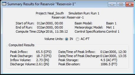
58 HEC-HMS Results Main Drainage Channel and Detention Pond Area Area (sq mi) Initial Abstraction (in) Curve Number Impervious (%) Main Drainage Area
59
60 Burns & McDonnell World Headquarters 9400 Ward Parkway Kansas City, MO O F
Inflow Design Flood Control System Plan for Louisa Generating Station CCR Impoundment. MidAmerican Energy Company
 Control System Plan for Louisa Generating Station CCR Impoundment MidAmerican Energy Company October 10, 2016 Control System Plan for Louisa Generating Station CCR Impoundment Prepared for MidAmerican
ATTACHMENT 6 WATER QUALITY SWALE DESIGN ADDENDUM
 ATTACHMENT 6 WATER QUALITY SWALE DESIGN ADDENDUM 12 October 2010 Project No. 073-81694.0022 Mr. Robert R. Monok Project Manager Energy Fuels Resource Corporation 44 Union Boulevard, Suite 600 Lakewood,
INITIAL RUN-ON AND RUN-OFF CONTROL PLAN 40 C.F.R. PART 257
 INITIAL RUN-ON AND RUN-OFF CONTROL PLAN 40 C.F.R. PART 257.81 HUFFAKER ROAD (PLANT HAMMOND) PRIVATE INDUSTRIAL LANDFILL (HUFFAKER ROAD LANDFILL) GEORGIA POWER COMPANY EPA s Disposal of Coal Combustion
CCR Monofill Location Restriction Demonstration. MidAmerican Energy Company, Louisa Generating Station
 CCR Monofill Location Restriction Demonstration MidAmerican Energy Company, Louisa Generating Station Final October 17, 2018 CCR Monofill Location Restriction Demonstration Prepared for MidAmerican Energy
RUN-ON AND RUN-OFF CONTROL SYSTEM PLAN
 RUN-ON AND RUN-OFF CONTROL SYSTEM PLAN FOR THE: SOUTHWESTERN ELECTRIC POWER COMPANY FLINT CREEK POWER PLANT LANDFILL CLASS 3N LANDFILL PERMIT 0273-S3N-R2 PREPARED FOR: SOUTHWESTERN ELECTRIC POWER COMPANY
STORMWATER RUN-ON AND RUN-OFF CONTROL PLAN ENTERGY ARKANSAS, INC. WHITE BLUFF PLANT CLASS 3N CCR LANDFILL
 STORMWATER RUN-ON AND RUN-OFF CONTROL PLAN ENTERGY ARKANSAS, INC. WHITE BLUFF PLANT CLASS 3N CCR LANDFILL PERMIT NO. 199-S3N-R3 AFIN: 3-11 OCTOBER 13, 216 STORMWATER RUN-ON AND RUN-OFF CONTROL PLAN ENTERGY
Run-on and Run-off Control System Plan
 Run-on and Run-off Control System Plan For Compliance with the Coal Combustion Residuals Rule (40 CFR 257.81) Pawnee Station CCR Landfill Public Service Company of Colorado Denver, Colorado October 17,
Technical Memorandum
 Tucson Office 3031 West Ina Road Tucson, AZ 85741 Tel 520.297.7723 Fax 520.297.7724 www.tetratech.com Technical Memorandum To: Kathy Arnold From: Greg Hemmen, P.E. Company: Rosemont Copper Company Date:
Closure Plan Brame Fly Ash Pond
 Brame Fly Ash Pond CLECO Corporation Rodemacher Unit 2 Project No. 90965 Revision 0 10/14/2016 Brame Fly Ash Pond prepared for CLECO Corporation Rodemacher Unit 2 Rapides Parish, Louisiana Project No.
Annual Inspection Report North CCR Surface Impoundment. MidAmerican Energy Company, Walter Scott Energy Center
 Annual Inspection Report North CCR Surface Impoundment MidAmerican Energy Company, Walter Scott Energy Center Rev 0 July 2018 Annual Inspection Report North CCR Surface Impoundment Prepared for MidAmerican
INFLOW DESIGN FLOOD CONTROL SYSTEM PLAN 40 C.F.R. PART PLANT YATES ASH POND 3 (AP-3) GEORGIA POWER COMPANY
 GEORGIA POWER COMPANY") INFLOW DESIGN FLOOD CONTROL SYSTEM PLAN 40 C.F.R. PART 257.82 PLANT YATES ASH POND 3 (AP-3) GEORGIA POWER COMPANY EPA s Disposal of Coal Combustion Residuals from Electric Utilities Final Rule (40 C.F.R.
INFLOW DESIGN FLOOD CONTROL SYSTEM PLAN 40 C.F.R. PART 257.82 PLANT YATES ASH POND 3 (AP-3) GEORGIA POWER COMPANY EPA s Disposal of Coal Combustion Residuals from Electric Utilities Final Rule (40 C.F.R.
RUN-ON AND RUN-OFF CONTROL PLAN 40 C.F.R. PART PLANT DANIEL NORTH ASH MANAGEMENT UNIT MISSISSIPPI POWER COMPANY
 RUN-ON AND RUN-OFF CONTROL PLAN 40 C.F.R. PART 257.81 PLANT DANIEL NORTH ASH MANAGEMENT UNIT MISSISSIPPI POWER COMPANY EPA s Disposal of Coal Combustion Residuals from Electric Utilities Final Rule (40
Contents. Drainage Analysis: Hunters Trace, Westpointe, and Hunters Creek
 Drainage Analysis: Hunters Trace, Westpointe, and Hunters Creek Contents SITE LOCATION / DESCRIPTION... 3 WESTPOINTE STORMWATER MANAGEMENT PLAN... 3 THE ENCLAVE AT WESTPOINTE DETENTION POND... 3 Table
Annual Inspection Report CCR Surface Impoundment. MidAmerican Energy Company, Louisa Generating Station
 Annual Inspection Report CCR Surface Impoundment MidAmerican Energy Company, Louisa Generating Station Final January 15, 2016 Annual Inspection Report CCR Surface Impoundment Prepared for MidAmerican Energy
WELSH POWER PLANT ASH LANDFILL. Run-on and Run-off Control System Plan
 WELSH POWER PLANT ASH LANDFILL Run-on and Run-off Control System Plan SEPTEMBER 27, 2016 PREPARED BY: MTG TEXAS FIRM REGISTRATION NUMBER: 354 MTG PROJECT NUMBER: 167003 WELSH POWER PLANT - ASH LANDFILL
STORMWATER RUN-ON AND RUN-OFF CONTROL PLAN ENTERGY ARKANSAS, INC. INDEPENDENCE PLANT CLASS 3N CCR LANDFILL
 STORMWATER RUN-ON AND RUN-OFF CONTROL PLAN ENTERGY ARKANSAS, INC. INDEPENDENCE PLANT CLASS 3N CCR LANDFILL PERMIT NO. 0200-S3N-R2 AFIN: 32-00042 OCTOBER 12, 2016 STORMWATER RUN-ON AND RUN-OFF CONTROL PLAN
INITIAL RUN-ON AND RUN-OFF CONTROL PLAN 40 C.F.R. PART 257
 INITIAL RUN-ON AND RUN-OFF CONTROL PLAN 40 C.F.R. PART 257.81 PLANT BOWEN PRIVATE INDUSTRY SOLID WASTE DISPOSAL FACILITY (ASH LANDFILL) GEORGIA POWER COMPANY EPA s Disposal of Coal Combustion Residuals
Run-on and Run-off Control System Plan
 Run-on and Run-off Control System Plan CCR Temporary Storage Pad Lewis and Clark Station Prepared for Montana-Dakota Utilities Co. October 2016 Paul T. Swenson 2016.10.13 18:30:03-05'00' 234 West Century
LAKE COUNTY HYDROLOGY DESIGN STANDARDS
 LAKE COUNTY HYDROLOGY DESIGN STANDARDS Lake County Department of Public Works Water Resources Division 255 N. Forbes Street Lakeport, CA 95453 (707)263-2341 Adopted June 22, 1999 These Standards provide
City of Fort Collins. Spring Creek Place (2105 South College Avenue) Preliminary Drainage Report
 Preliminary Drainage Report") City of Fort Collins Spring Creek Place (2105 South College Avenue) Preliminary Drainage Report OCTOBER 2016 VERSION 3 Prepared By: 4582 South Ulster Street, Suite 1500 Denver, CO 80237 Daniel L. Skeehan,
City of Fort Collins Spring Creek Place (2105 South College Avenue) Preliminary Drainage Report OCTOBER 2016 VERSION 3 Prepared By: 4582 South Ulster Street, Suite 1500 Denver, CO 80237 Daniel L. Skeehan,
INITIAL INFLOW DESIGN FLOOD CONTROL SYSTEM PLAN PLANT MCMANUS ASH POND A (AP-1) 40 CFR
 40 CFR") INITIAL INFLOW DESIGN FLOOD CONTROL SYSTEM PLAN PLANT MCMANUS ASH POND A (AP-1) 40 CFR 257.82 EPA s Disposal of Coal Combustion Residuals from Electric Utilities Final Rule (40 C.F.R. Part 257 and Part
INITIAL INFLOW DESIGN FLOOD CONTROL SYSTEM PLAN PLANT MCMANUS ASH POND A (AP-1) 40 CFR 257.82 EPA s Disposal of Coal Combustion Residuals from Electric Utilities Final Rule (40 C.F.R. Part 257 and Part
INFLOW DESIGN FLOOD CONTROL SYSTEM PLAN PLANT GREENE COUNTY ASH POND ALABMA POWER COMPANY
 INFLOW DESIGN FLOOD CONTROL SYSTEM PLAN PLANT GREENE COUNTY ASH POND ALABMA POWER COMPANY Section 257.82 of EPA s regulations requires the owner or operator of an existing or new CCR surface impoundment
CHELTENHAM TOWNSHIP Chapter 290: WATERSHED STORMWATER MANAGEMENT Article IV: Stormwater Management
 CHELTENHAM TOWNSHIP Chapter 290: WATERSHED STORMWATER MANAGEMENT Article IV: Stormwater Management Online ECode Available on Cheltenham Township Website at: http://ecode360.com/14477578 For all regulated
INFLOW DESIGN FLOOD CONTROL SYSTEM PLAN 40 C.F.R. Part PLANT MCINTOSH ASH POND 1 GEORGIA POWER COMPANY
 INFLOW DESIGN FLOOD CONTROL SYSTEM PLAN 40 C.F.R. Part 257.82 PLANT MCINTOSH ASH POND 1 GEORGIA POWER COMPANY EPA s Disposal of Coal Combustion Residuals from Electric Utilities Final Rule (40 C.F.R. Part
Module 3: Rainfall and Hydrology for Construction Site Erosion Control
 Module 3: Rainfall and Hydrology for Construction Site Erosion Control Robert Pitt Department of Civil, Construction, and Environmental Engineering University of Alabama Tuscaloosa, AL Rainfall and Hydrology
INFLOW DESIGN FLOOD CONTROL SYSTEM PLAN 40 C.F.R. PART PLANT DANIEL ASH POND B MISSISSIPPI POWER COMPANY
 INFLOW DESIGN FLOOD CONTROL SYSTEM PLAN 40 C.F.R. PART 257.82 PLANT DANIEL ASH POND B MISSISSIPPI POWER COMPANY EPA s Disposal of Coal Combustion Residuals from Electric Utilities Final Rule (40 C.F.R.
PEARCE CREEK CONFINED DISPOSAL AREA MODIFICATION
 US Army Corps of Engineers Philadelphia District PEARCE CREEK CONFINED DISPOSAL AREA MODIFICATION CECIL COUNTY MARYLAND STORMWATER MANAGEMENT PLAN NARRATIVE INITIAL SUBMISSION JUNE 2014 1 PEARCE CREEK
INFLOW DESIGN FLOOD CONTROL SYSTEM PLAN. Bremo Power Station CCR Surface Impoundment: North Ash Pond INFLOW DESIGN FLOOD
 INFLOW DESIGN FLOOD CONTROL SYSTEM PLAN INFLOW DESIGN FLOOD CONTROL SYSTEM PLAN Bremo Power Station CCR Surface Impoundment: North Ash Pond Submitted To: Bremo Power Station 1038 Bremo Bluff Road Bremo
Inflow Design Flood Control System Plan
 Inflow Design Flood Control System Plan Scrubber Ponds Lewis and Clark Station Prepared for Montana-Dakota Utilities Co. October 2016 Paul T. Swenson 2016.10.14 17:54:29-05'00' 234 West Century Avenue
INFLOW DESIGN FLOOD CONTROL SYSTEM PLAN 40 C.F.R. PART PLANT YATES ASH POND B (AP-B ) GEORGIA POWER COMPANY
 GEORGIA POWER COMPANY") INFLOW DESIGN FLOOD CONTROL SYSTEM PLAN 40 C.F.R. PART 257.82 PLANT YATES ASH POND B (AP-B ) GEORGIA POWER COMPANY EPA s Disposal of Coal Combustion Residuals from Electric Utilities Final Rule (40 C.F.R.
INFLOW DESIGN FLOOD CONTROL SYSTEM PLAN 40 C.F.R. PART 257.82 PLANT YATES ASH POND B (AP-B ) GEORGIA POWER COMPANY EPA s Disposal of Coal Combustion Residuals from Electric Utilities Final Rule (40 C.F.R.
INFLOW DESIGN FLOOD CONTROL SYSTEM PLAN PLANT GASTON GYPSUM POND ALABAMA POWER COMPANY
 INFLOW DESIGN FLOOD CONTROL SYSTEM PLAN PLANT GASTON GYPSUM POND ALABAMA POWER COMPANY Section 257.82 of EPA s regulations requires the owner or operator of an existing or new CCR surface impoundment or
Drainage Analysis. Appendix E
 Drainage Analysis Appendix E The existing and proposed storm drainage systems have been modeled with Bentley CivilStorm V8 computer modeling software. The peak stormwater discharge was determined for
Rational Method Hydrological Calculations with Excel COURSE CONTENT
 Rational Method Hydrological Calculations with Excel Harlan H. Bengtson, PhD, P.E. COURSE CONTENT 1. Introduction Calculation of peak storm water runoff rate from a drainage area is often done with the
INFLOW DESIGN FLOOD CONTROL SYSTEM PLAN PLANT BARRY ASH POND ALABAMA POWER COMPANY
 INFLOW DESIGN FLOOD CONTROL SYSTEM PLAN PLANT BARRY ASH POND ALABAMA POWER COMPANY Section 257.82 of EPA s regulations requires the owner or operator of an existing or new CCR surface impoundment or any
PRELIMINARY DRAINAGE STUDY
 PRELIMINARY DRAINAGE STUDY For 34 th & J Residences 3402 J St. San Diego, CA 92102 A.P.N 545-250-08 Prepared By: Kenneth J. Discenza, P.E. Site Design Associates, Inc. 1016 Broadway, Suite A El Cajon,
0.0. Pervious CN = 40. (Unconnected impervious) (Total impervious) Total impervious area (percent) Composite CN
 (Total impervious) Total impervious area (percent) Composite CN") Figure 2-3 Composite CN with connected impervious area. 100 Composite CN 90 80 70 60 Pervious CN = 90 80 70 60 50 40 50 40 0 10 20 30 40 50 60 70 80 90 100 Connected impervious area (percent) Figure 2-4
Figure 2-3 Composite CN with connected impervious area. 100 Composite CN 90 80 70 60 Pervious CN = 90 80 70 60 50 40 50 40 0 10 20 30 40 50 60 70 80 90 100 Connected impervious area (percent) Figure 2-4
INITIAL RUN-ON AND RUN-OFF CONTROL SYSTEM PLAN Sibley CCR Landfill Sibley Generating Station East Johnson Rd Sibley, Missouri
 INITIAL RUN-ON AND RUN-OFF CONTROL SYSTEM PLAN Sibley CCR Landfill Sibley Generating Station 33200 East Johnson Rd Sibley, Missouri KCP&L Greater Missouri Operations Company October 17, 2016 TABLE OF CONTENTS
Report. Inflow Design Flood Control System Plan Belle River Power Plant East China, Michigan. DTE Energy Company One Energy Plaza, Detroit, MI
 Report Inflow Design Flood Control System Plan Belle River Power Plant East China, Michigan DTE Energy Company One Energy Plaza, Detroit, MI October 14, 2016 NTH Project No. 62-160047-04 NTH Consultants,
Environmental Design Group
 SEDIMENT CONTROL DURING CONSTRUCTION, STORMWATER MANAGEMENT AND POST CONSTRUCTION BMP REPORT for Hudson Salt Storage and Bus Garage 5810 Hudson Drive HUDSON, OHIO SUMMIT COUNTY Prepared by Environmental
January 20, Nate Hatleback Project Manager, City of Thornton Development Engineering 9500 Civic Center Drive Thornton, CO (303)
") January 20, 2017 Nate Hatleback Project Manager, City of Thornton Development Engineering 9500 Civic Center Drive Thornton, CO 80229 (303) 538-7694 RE: Riverdale Five Retail Drainage Conformance Letter
January 20, 2017 Nate Hatleback Project Manager, City of Thornton Development Engineering 9500 Civic Center Drive Thornton, CO 80229 (303) 538-7694 RE: Riverdale Five Retail Drainage Conformance Letter
Introduction to Storm Sewer Design
 A SunCam online continuing education course Introduction to Storm Sewer Design by David F. Carter Introduction Storm sewer systems are vital in collection and conveyance of stormwater from the upstream
INFLOW DESIGN FLOOD CONTROL SYSTEM PLAN 40 C.F.R. PART PLANT BOWEN ASH POND 1 (AP-1) GEORGIA POWER COMPANY
 GEORGIA POWER COMPANY") INFLOW DESIGN FLOOD CONTROL SYSTEM PLAN 40 C.F.R. PART 257.82 PLANT BOWEN ASH POND 1 (AP-1) GEORGIA POWER COMPANY EPA s Disposal of Coal Combustion Residuals from Electric Utilities Final Rule (40 C.F.R.
INFLOW DESIGN FLOOD CONTROL SYSTEM PLAN 40 C.F.R. PART 257.82 PLANT BOWEN ASH POND 1 (AP-1) GEORGIA POWER COMPANY EPA s Disposal of Coal Combustion Residuals from Electric Utilities Final Rule (40 C.F.R.
Inflow Design Flood Control System Plan
 Inflow Design Flood Control System Plan Scrubber Ponds Lewis & Clark Station Prepared for Montana-Dakota Utilities Co. November 2018 234 West Century Avenue Bismarck, ND 58503 701.255.5460 www.barr.com
BMP Design Aids. w w w. t r a n s p o r t a t i o n. o h i o. g o v. Equations / Programs
 BMP Design Aids 1 Equations / Programs Outlet Discharge Equations Hydrograph and Pond Routing Programs USGS StreamStats 2 Ohio Department of Transportation 1 Training Intent Introduction and overview of
Chapter 6. Hydrology. 6.0 Introduction. 6.1 Design Rainfall
 6.0 Introduction This chapter summarizes methodology for determining rainfall and runoff information for the design of stormwater management facilities in the City. The methodology is based on the procedures
CCR Rule Operating Criteria Closure Plan
 CCR Rule Operating Criteria 257.102 Closure Plan FGD Pond 2 Jim Bridger Plant Point of Rocks, Wyoming PREPARED FOR PacifiCorp 1407 West North Temple Salt Lake City, UT 84116 (801) 521-0376 Fax (801) 220-4748
Appendix 10-A. Optional Recharge Volume Approach
 Appendix 10-A Optional Recharge Volume Approach Table of Contents APPENDIX SECTION HEADINGS 10-A.0 INTRODUCTION 10-A-2 10-A.1 Horsely Method for Determining Recharge Volumes 10-A-2 10-A.1.1 Basis for Determining
STORMWATER MANAGEMENT REPORT FOR THE BORGATA OUTDOOR EVENT AREA POOL ADDITION
 STORMWATER MANAGEMENT REPORT FOR THE BORGATA OUTDOOR EVENT AREA POOL ADDITION City of Atlantic City, Atlantic County, New Jersey Prepared For: Marina District Development Company, LLC One Borgata Way Atlantic
Table of Contents. List of Appendices. October 2016 i
 October 2016 i 1663066 Table of Contents 1.0 INTRODUCTION... 1 2.0 REGULATORY REQUIREMENTS... 1 3.0 DESIGN METHODOLOGY... 1 3.1 Design Storm... 1 3.2 Rainfall Abstractions... 1 3.3 Routing Methodology...
STORMWATER HYDROLOGY
 ..CHAPTER.. STORMWATER HYDROLOGY 3.1 Introduction to Hydrologic Methods Hydrology is the science dealing with the characteristics, distribution, and movement of water on and below the earth's surface and
Stantec Consulting Services Inc Lebanon Road, Cincinnati, OH 45241
 Stantec Consulting Services Inc. 11687 Lebanon Road, Cincinnati, OH 45241 File: 175534017 Revision 0 Ohio Valley Electric Corporation 3932 U.S. Route 23 P.O. Box 468 Piketon, Ohio 45661 RE: Run-on and
Stormwater Management Studies PDS Engineering Services Division ES Policy # 3-01
 Stormwater Management Studies PDS Engineering Services Division Revised Date: 2/28/08 INTRODUCTION The City of Overland Park requires submission of a stormwater management study as part of the development
Standards for Soil Erosion and Sediment Control in New Jersey May 2012 STANDARD FOR GRASSED WATERWAYS. Definition. Purpose
 STANDARD FOR GRASSED WATERWAYS Definition A natural or constructed watercourse shaped or graded in earth materials and stabilized with suitable vegetation for the safe conveyance of runoff water. Purpose
Report. Inflow Design Flood Control System Plan St. Clair Power Plant St. Clair, Michigan. DTE Energy Company One Energy Plaza, Detroit, MI
 Report Inflow Design Flood Control System Plan St. Clair Power Plant St. Clair, Michigan DTE Energy Company One Energy Plaza, Detroit, MI October 14, 2016 NTH Project No. 62-160047-04 NTH Consultants,
RETENTION BASIN EXAMPLE
 -7 Given: Total Tributary Area = 7.5 ac o Tributary Area within Existing R/W = 5.8 ac o Tributary Area, Impervious, Outside of R/W = 0.0 ac o Tributary Area, Pervious, Outside of R/W = 1.7 ac o Tributary
Stormwater Erosion Control & Post-Construction Plans (Stormwater Quality Plans)
") Stormwater Erosion Control & Post-Construction Plans (Stormwater Quality Plans) Allen County Stormwater Plan Submittal Checklist The following items must be provided when applying for an Allen County Stormwater
Stormwater Erosion Control & Post-Construction Plans (Stormwater Quality Plans) Allen County Stormwater Plan Submittal Checklist The following items must be provided when applying for an Allen County Stormwater
INITIAL HAZARD POTENTIAL CLASSIFICATION ASSESSMENT REPORT. Fly Ash Impoundment KCP&L Greater Missouri Operations Company Sibley Generating Station
 INITIAL HAZARD POTENTIAL CLASSIFICATION ASSESSMENT REPORT Fly Ash Impoundment KCP&L Greater Missouri Operations Company Sibley Generating Station File No. 27216295.00 Prepared by: SCS ENGINEERS 7311 West
D. B. Wilson Station CCR Landfill
 D. B. Wilson Station CCR Landfill Disposal of Coal Combustion Residuals (CCR) from Electric Utilities Final Rule Run-on and Run-off Control System Plan October 11, 2016 Revised September 19, 2017 Prepared
Annual Fugitive Dust Report for the Walter Scott, Jr. Energy Center
 for the MidAmerican Energy Company Coal Combustion Residual Rule Compliance November 2017 for the Walter Scott, Jr. Energy Center Prepared for MidAmerican Energy Company Coal Combustion Residual Rule Compliance
FORT COLLINS STORMWATER CRITERIA MANUAL Hydrology Standards (Ch. 5) 1.0 Overview
 1.0 Overview") Chapter 5: Hydrology Standards Contents 1.0 Overview... 1 1.1 Storm Runoff Determination... 1 1.2 Design Storm Frequencies... 1 1.3 Water Quality Storm Provisions... 2 1.4 Design Storm Return Periods...
Chapter 5: Hydrology Standards Contents 1.0 Overview... 1 1.1 Storm Runoff Determination... 1 1.2 Design Storm Frequencies... 1 1.3 Water Quality Storm Provisions... 2 1.4 Design Storm Return Periods...
Ponds Planning, Design, Construction
 United States Department of Agriculture Natural Resources Conservation Service Ponds Planning, Design, Construction Agriculture Handbook Number 590 Estimating storm runoff The amount of precipitation,
APPENDIX IV. APPROVED METHODS FOR QUANTIFYING HYDROLOGIC CONDITIONS OF CONCERN (NORTH ORANGE COUNTY)
") APPENDIX IV. APPROVED METHODS FOR QUANTIFYING HYDROLOGIC CONDITIONS OF CONCERN (NORTH ORANGE COUNTY) Hydromodification design criteria for the North Orange County permit area are based on the 2- yr, 24-hr
APPENDIX IV. APPROVED METHODS FOR QUANTIFYING HYDROLOGIC CONDITIONS OF CONCERN (NORTH ORANGE COUNTY) Hydromodification design criteria for the North Orange County permit area are based on the 2- yr, 24-hr
NEW CASTLE CONSERVATION DISTRICT. through. (Name of Municipality) PLAN REVIEW APPLICATION DRAINAGE, STORMWATER MANAGEMENT, EROSION & SEDIMENT CONTROL
 PLAN REVIEW APPLICATION DRAINAGE, STORMWATER MANAGEMENT, EROSION & SEDIMENT CONTROL") NEW CASTLE CONSERVATION DISTRICT through (Name of Municipality) PLAN REVIEW APPLICATION DRAINAGE, STORMWATER MANAGEMENT, EROSION & SEDIMENT CONTROL Office use only: Received by Municipality: Received by
NEW CASTLE CONSERVATION DISTRICT through (Name of Municipality) PLAN REVIEW APPLICATION DRAINAGE, STORMWATER MANAGEMENT, EROSION & SEDIMENT CONTROL Office use only: Received by Municipality: Received by
ENGN.4010 ENGINEERING CAPSTONE DESIGN Watershed Analysis. CiA
 RATIONAL METHOD Q CiA Where: Q = Maximum Rate of Runoff (cfs) C = Runoff Coefficient i = Average Rainfall Intensity (in/hr) A = Drainage Area (in acres) RATIONAL METHOD Assumptions and Limitations: Watershed
COON CREEK WATERSHED DISTRICT PERMIT REVIEW Mississippi Dr Coon Rapids, MN SQ FT Residence on 0.64 Acre Lot
 17-082 Van Sloun Residence, Page 1 of 5 COON CREEK WATERSHED DISTRICT PERMIT REVIEW MEETING DATE: May 8, 2017 AGENDA NUMBER: 17 FILE NUMBER: 17-082 ITEM: Van Sloun Residence RECOMMENDATION: Approve with
Annual Fugitive Dust Report for the Walter Scott, Jr. Energy Center
 Annual Fugitive Dust Report for the MidAmerican Energy Company Coal Combustion Residual Rule Compliance November 2018 Annual Fugitive Dust Report for the Walter Scott, Jr. Energy Center Prepared for MidAmerican
Table of Contents CHAPTER. Chapter 2 Hydrologic Analysis. 2.1 Estimating Runoff
 CHAPTER Table of Contents 2 Chapter 2 Hydrologic Analysis 2.1 Estimating Runoff 2.1.1 Introduction to Hydrologic Methods...2.1-1 2.1.2 Symbols and Definitions...2.1-4 2.1.3 Rainfall Estimation...2.1-5
Project Drainage Report
 Design Manual Chapter 2 - Stormwater 2A - General Information 2A-4 Project Drainage Report A. Purpose The purpose of the project drainage report is to identify and propose specific solutions to stormwater
6.0 Runoff. 6.1 Introduction. 6.2 Flood Control Design Runoff
 October 2003, Revised February 2005 Chapter 6.0, Runoff Page 1 6.1 Introduction 6.0 Runoff The timing, peak rates of discharge, and volume of stormwater runoff are the primary considerations in the design
Applying the Water Quality Volume
 Applying the Water Quality Volume Justin Reinhart, PE Division of Surface Water Northeast Ohio Stormwater Training Council Cleveland, Ohio & Richfield, Ohio July 12, 2018 July 25, 2018 Post-Construction
Design of Stormwater Wetlands
 Hydraulic & Hydrologic Stormwater Engineering Design of Stormwater Wetlands Jon Hathaway, EI Extension Associate NCSU Bio. And Ag. Engineering 6 Step Process 1. Watershed Analysis (Runoff Volume and Peak
The site slopes generally from the southwest to northeast at approximately 3.7 percent.
 March 3, 2017 Nate Hatleback Project Manager, City of Thornton Development Engineering 9500 Civic Center Drive Thornton, CO 80229 (303) 538-7694 RE: Riverdale Five Retail Drainage Conformance Letter Dear
COON CREEK WATERSHED DISTRICT PERMIT REVIEW. Spring Lake Park Schools Westwood Middle School st Avenue NE, Spring Lake Park, MN 55432
 PAN 16-112, Westwood Middle School, Page 1 of 6 COON CREEK WATERSHED DISTRICT PERMIT REVIEW MEETING DATE: August 22, 2016 AGENDA NUMBER: 10 FILE NUMBER: 16-112 ITEM: Westwood Middle School RECOMMENDATION:
DRAINAGE REPORT. Project Name: PG&E Gas Operations Technical Training Center Winters, CA. Date: February 4, Prepared by: BKF Engineers
 DRAINAGE REPORT Project Name: PG&E Gas Operations Technical Training Center Winters, CA Date: February 4, 2015 Prepared by: BKF Engineers Client: Pacific Gas & Electric Company This report has been prepared
Typical Local Erosion Control Requirements (Storm Water Management Authority, Inc.)
") Module 2: Selection of Controls and Site Planning for Construction Site Erosion Prevention Robert Pitt Department of Civil, Construction, and Environmental Engineering University of Alabama Tuscaloosa,
Module 2: Selection of Controls and Site Planning for Construction Site Erosion Prevention Robert Pitt Department of Civil, Construction, and Environmental Engineering University of Alabama Tuscaloosa,
2. DEFINITIONS. American Association of State Highway and Transportation Officials.
 2. DEFINITIONS 2.010 Definitions [See Amendment 2] In addition to words and terms that may be defined elsewhere in this manual, the following words and terms shall have the meanings defined below: AASHTO:
Preliminary Drainage Analysis
 Preliminary Drainage Analysis Tanimura and Antle Employee Housing Town of Spreckels County of Monterey, California LIB150205 May 29, 2015 Prepared For: Tanimura and Antle Produce Prepared By: 9699 Blue
VISUAL SITE INSPECTION REPORT
 VISUAL SITE INSPECTION REPORT - 2016 SOUTHERN INDIANA GAS AND ELECTRIC A. B. BROWN GENERATING STATION TYPE III RESTRICTED WASTE LANDFILL WEST FRANKLIN, IN ATC PROJECT NO. 170LF00318 DECEMBER 20, 2016 PREPARED
Green Station CCR Surface Impoundment
 Green Station CCR Surface Impoundment Disposal of Coal Combustion Residuals (CCR) from Electric Utilities Final Rule Hydrologic and Hydraulic Capacity Assessment and Initial Inflow Design Flood Control
Chapter Introduction. 5.2 Computational Standard Methods HYDROLOGY
 Chapter 5. HYDROLOGY 5.1 Introduction The definition of hydrology is the scientific study of water and its properties, distribution, and effects on the earth s surface, in the soil and the atmosphere.
Overview of NRCS (SCS) TR-20 By Dr. R.M. Ragan
 TR-20 By Dr. R.M. Ragan") Overview of NRCS (SCS) TR-20 By Dr. R.M. Ragan TR-20 is a computer program for the simulation of runoff occurring from a single storm event. The program develops flood hydrographs from runoff and routes
Overview of NRCS (SCS) TR-20 By Dr. R.M. Ragan TR-20 is a computer program for the simulation of runoff occurring from a single storm event. The program develops flood hydrographs from runoff and routes
FAST WATER / SLOW WATER AN EVALUATION OF ESTIMATING TIME FOR STORMWATER RUNOFF
 FAST WATER / SLOW WATER AN EVALUATION OF ESTIMATING TIME FOR STORMWATER RUNOFF Factors Affecting Stormwater Runoff: Rainfall intensity % Impervious surfaces Watershed size Slope Soil type, soil compaction
Run-on and Run-off Control System Plan
 Run-on and Run-off Control System Plan SWEPCO John W. Turk, Jr. Power Plant Fulton, Arkansas Permit No. 0311-S3N-R1 AFIN: 29-00506 October 2016 Terracon Project No. 35167133 Prepared for: SWEPCO 3711 Highway
100-yr Design Runoff (cfs) Basin ID 103b A a B B C Totals
 Basin ID 103b A a B B C Totals") PROPOSED DEVELOPMENT The drainage for this site has been designed to be less than the maximum allowable runoff from each basin as stated in the Overall Rigden Farm drainage plan. Table 1 compares the actual
PROPOSED DEVELOPMENT The drainage for this site has been designed to be less than the maximum allowable runoff from each basin as stated in the Overall Rigden Farm drainage plan. Table 1 compares the actual
SECTION 4 STORM DRAINAGE
 4.01 GENERAL SECTION 4 STORM DRAINAGE These standards shall provide minimum requirements for the design of Storm Drainage and related appurtenances within the City of West Sacramento rights of way and
STORM DRAINS AND IRRIGATION
 TABLE OF CONTENTS PART III - MINIMUM DESIGN STANDARDS Section 105 STORM DRAINS AND IRRIGATION 105.1. STORM DRAINS... 105.1 105.2. METHODS OF ANALYSIS... 105.1 105.2.1. Rational Method... 105.1 105.2.2.
Pre-Treatment Bioretention Cells Bioswales IOWA STORMWATER MANAGEMENT MANUAL DECEMBER 16, 2015
 Pre-Treatment Bioretention Cells Bioswales IOWA STORMWATER MANAGEMENT MANUAL DECEMBER 16, 2015 Urban Runoff Background How we got here What Problem?? Provenance of the Problem Unified Sizing Criteria What
Chapter 4. Drainage Report and Construction Drawing Submittal Requirements
 4.0 Introduction The requirements presented in this section shall be used to aid the design engineer or applicant in the preparation of drainage reports, drainage studies, and construction drawings for
Stormwater Analysis Report
 Stormwater Analysis Report Solar Panel Array Temple Street (Rt. 14) West Boylston, MA February 24, 216 SITE Prepared for: West Boylston Municipal Lighting Plant 4 Crescent Street West Boylston, MA 1583
Stormwater Local Design Manual For Houston County, Georgia
 Stormwater Local Design Manual For Houston County, Georgia Adopted November 15, 2005 TABLE OF CONTENTS 1. FORWARD... 1 2. GENERAL LEVEL OF SERVICE STANDARDS... 2 2.1. DETENTION REQUIREMENTS... 2 2.1.1.
PRELIMINARY DRAINAGE REPORT NEWCASTLE FIRE STATION OLD STATE HIGHWAY
 PRELIMINARY DRAINAGE REPORT FOR THE NEWCASTLE FIRE STATION OLD STATE HIGHWAY PREPARED FOR THE NEWCASTLE FIRE PROTECTION DISTRICT JULY 2014 BY ROSEVILLE DESIGN GROUP, INC. ROSEVILLE DESIGN GROUP, Inc Established
HYDROLOGY CHECKLIST FOR LAND DISTURBANCE PERMITS
 HYDROLOGY CHECKLIST FOR LAND DISTURBANCE PERMITS Project Name: Project Number: Reviewed By: Date: Telephone: Email: Address all items marked with an X Minimum Submittal Requirements 1. Conceptual Review
iswm TM Technical Manual Hydrology:
 : 1.0 2.0 Downstream Assessment 3.0 Streambank Protection 4.0 Water Balance 5.0 Rainfall Tables 6.0 Hydrologic Soils Data Table of Contents 1.0... HO-1 1.1 Estimating Runoff... HO-1 1.1.1 Introduction
MVP 17.3 WATER BAR END TREATMENT SIZING AND DETAILS 1/22/18
 MVP 17.3 WATER BAR END TREATMENT SIZING AND DETAILS 1/22/18 The purpose of this detail is to document the methodology developed to size the length of the water bar end treatments to ensure flow leaving
TABLE OF CONTENTS PART III - MINIMUM DESIGN STANDARDS Section 105 DRAINAGE SYSTEM DESIGN SPECIFICATIONS AND SCOPE 105.1
 TABLE OF CONTENTS PART III - MINIMUM DESIGN STANDARDS Section 105 DRAINAGE SYSTEM DESIGN SECTION TITLE PAGE 105.1. SPECIFICATIONS AND SCOPE 105.1 105.2. METHODS OF ANALYSIS 105.1 105.2.1. Rational Method
SECTION IV WATERSHED TECHNICAL ANALYSIS
 A. Watershed Modeling SECTION IV WATERSHED TECHNICAL ANALYSIS An initial step in the preparation of this stormwater management plan was the selection of a stormwater simulation model to be utilized. It
CHOLLA POWER PLANT BOTTOM ASH POND INFLOW DESIGN FLOOD CONTROL SYSTEM PLAN CH_Inflowflood_003_
 CHOLLA POWER PLANT BOTTOM ASH POND INFLOW DESIGN FLOOD CONTROL SYSTEM PLAN CH_Inflowflood_003_20161017 This Inflow Design Flood Control System Plan (Plan) document has been prepared specifically for the
Appendix B Stormwater Site Plan Submittal Requirements Checklist
 Stormwater Site Plan Submittal Requirements Checklist The Submittal Requirements Checklist is intended to aid the design engineer in preparing a Stormwater Site Plan. All items included in the following
Chapter 2: Conditions in the Spring Lake Watershed related to Stormwater Pollution
 Chapter 2: Conditions in the Spring Lake Watershed related to Stormwater Pollution To identify the primary causes and consequences of stormwater discharges to Spring Lake and its adjoining waterbodies,
Modeling Infiltration BMPs
 Modeling Infiltration BMPs CAHILL ASSOCIATES Environmental Consultants West Chester, PA (610) 696-4150 www.thcahill.com Design Goals for Calculations 1. Mitigate Peak Rates 2-Year to 100-Year 2. No Volume