Interlake Tunnel Project
|
|
|
- Julianna Gaines
- 5 years ago
- Views:
Transcription


1 Interlake Tunnel Project February 26,2015 Updated 3/19/15 Presentation at the Heritage Ranch Rec Barn 1
2 Agenda Introductions Project description and background Feasibility and hydraulic modeling San Antonio spillway modification description Environmental clearance and permitting Development schedule Cost and financing plan Questions and Answers 2
3 PROJECT BACKGROUND, DESCRIPTION AND FUNCTION 3
 Average Annual Amounts (AFY) 200,000 Less Evapotranspiration & Conveyance losses 40,000 SRDF deliveries 6,000 Ground water recharge Provides flood")
4 Existing Surface Water Supply for Salinas Valley properties 2 reservoirs, Salinas River, and Salinas River Diversion Facility Nacimiento San Antonio SRDF Salinas River Description Average annual controlled release from reservoirs (baseline) Average Annual Amounts (AFY) 200,000 Less Evapotranspiration & Conveyance losses 40,000 SRDF deliveries 6,000 Ground water recharge Provides flood control, minimum flows, and conservation releases 154,000 4


5 Tunnel has 37 year history from
6 1991 Analysis 6

7 1991 tunnel studies 7


8 Reservoirs Features San Antonio Max Capacity = 335,000 Acre Feet Nacimiento fills 3X faster than San Antonio Nacimiento Max Capacity = 377, 900 Acre Feet 8
9 Current Situation at Reservoirs Unused storage Nacimiento Reservoir San Antonio Reservoir Nacimiento fills 3 x faster than San Antonio San Antonio has unused storage Excess water spilled to ocean 9
10 Ratio of Calculated Annual Inflow Nacimiento over San Antonio (Water Years ) 1, Ratio Average Inflow Ratio = Annual Inflow Ratio Water Year Average Ratio Inflow ratios from WY 1977 and WY 1990 were omitted from the average ratio as outliers due to inconsistency with the long term trend. WY 1977 and WY 1990 were the lowest inflow years on record at San Antonio and do not represent typical inflow ratios.

11 Tunnel Project Fundamentals 60,000 AF additional storage by raising San Antonio spillway 10 Increased net storage Nacimiento Reservoir San Antonio Reservoir Increases net storage of reservoirs provides flood control and reduces flood spills 11
 Recharge groundwater")


12 Water supply sustainability Release water at opportune timing to: 1) Recharge groundwater aquifers 2) Supply suite of future projects 3) Augment deliveries to SRDF Tunnel transfers water from Nacimiento to San Antonio SRDF Aquifers Salinas River Tunnel Releases Natural inflow to Nacimiento Natural inflow to San Antonio Additional water available for: Supply to future projects Recharge groundwater 12

13 Interlake Tunnel Lake San Antonio Monterey County San Luis Obispo County Proposed tunnel alignment ~ 12,000 feet 10 diameter Concrete lined Gravity flow tunnel Lake Nacimiento 13

 14 Spillway elevation")
14 Portals and Tunnel Profile (conceptual) Ground surface 600 Tunnel Nacimiento portal San Antonio portal Portal Invert Elevation (~745 ) Spillway elevation ~ 800 Portal Invert Elevation (~695') 14 Spillway elevation ~ 780

15 Nacimiento proposed intake Proposed Site for Nacimiento Intake Facility North Shore Access Ramp & Parking Road G14 Nacimiento Lake Nacimiento Water Project Intake Facility Spillway Dam 15
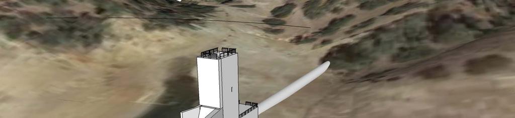

16 Nacimiento intake structure concept 16

17 San Antonio Hydraulic Structures Proposed San Antonio Energy Dissipator San Antonio Lake Dam Proposed San Antonio Outlet Valve Facility Spillway 17

18 San Antonio outlet concept 18


19 Tunnel rating curve 19


20 Tunnel concept Nacimiento Reservoir San Antonio Reservoir Tunnel Nacimiento Intake Structure San Antonio Valve Facility San Antonio Energy Dissipator 12, Tunnel maximum flow capacity ~ 1,700 CFS 20
21 Hydraulics Operation Criteria & Slope: ft/ft Assumptions Selected at initial stage of evaluation to parallel the friction slope, S f ; thus, Slope is about parallel to the water surface profile slope (hydraulic grade line) Slope greater than minimum slope of 0.001ft/ft Slope within range of other water tunnels Friction Loss Function: Darcy Weisbach Accounts for sidewall roughness, water viscosity, diameter, and length (TM HC.01) 21
22 Hydraulics Operation Criteria & Assumptions Invert EL: ft NGVD29 Selected to correspond with water transfer trigger elevation of 760 ft in Lake Nacimiento Crown of Intake Submerged Tunnel will flow full if water surface profile is greater than tunnel crown Final Designer to perform detailed water surface profile (HGL) computation to verify hydraulics, including slopes and elevations (TM HC.01) 22
23 Hydraulics Operation Criteria & Assumptions Flow Control: Downstream Spherical Valve d/s control allows tunnel to flow full Nacimiento Reservoir San Antonio Reservoir Tunnel Intake Structure Spherical Valve Outlet Structure (TM HC.01) 23
24 Why is Flowing Full Important? Technical Life of Tunnel > 100 years Steady Flow Streamlines Improve Longevity Partial Flow Jeopardizes Longevity Partial Flow: Severe Dynamic Transitions 24

25 Why is Flowing Full Important? This Condition is Acceptable When Tailwater Never Submerges Outlet This Condition Is Problematic in Long High Capacity Tunnel Configurations 25


26 Hydraulic Jump inside Stilling Basin Designed for Hyd. Jumps Tailwater Promotes Jump Stability Within Confines of Basin Hydraulic Jump Inside Tunnel Not Designed for Hyd. Jump Tailwater Not Consistent Trapped Air Restricts Flow Jump Moves Around

, can tolerate high velocities, full port opening.")
27 Hydraulics Operation Criteria & Flow Control Assumptions Spherical Valve: Allows for sealing with head on both side of valve, allows for partial open operation (can throttle flow), can tolerate high velocities, full port opening. (TM HC.01) 27
28 FEASIBILITY AND HYDRAULIC MODELING 28
29 Hydrologic model fundamentals Water rights limitations: Each reservoir is operated within its water rights. Nacimiento has 17,500 afy consumptive demands Water supply requirements: Block flows are released when called for Minimum Flow Requirements are met from each reservoir. Reservoir Balancing to meet Salinas River Diversion Facility (SRDF) demands is achieved through: releases from Nacimiento up to capacity of hydroelectric plant remaining releases, if required, are made from San Antonio Reservoir. 29
30 Proposed tunnel operating concepts Operate on head relationships between inflow and outflow in a pressure flow mode. Water conveyance through tunnel when the Nacimiento surface water elevation is above 760 feet. No water conveyance through the tunnel when San Antonio is spilling. 30
31 Hydrologic Modeling OASIS Computer Operational Simulation Model Schematic 31
32 1,200,000 1,000, , , , ,000 Combined Nacimiento and San Antonio Inflow by Water Year Type (Water Years ) Count of Water Year Types Wet: 15 Normal: 19 Dry: 13 0 Combined Inflow (acre feet) Water Year Wet Normal Dry
33 Nacimiento Lake elevation (annual average) Nacimiento Lake Level Baseline 760'
34 Tunnel Transfers Storage from Nacimiento to San Antonio Nacimiento capacity Without tunnel, spill occurs at Nacimiento 795 San Antonio capacity ~ Nacimiento lake elevation 34
35 Hydrograph Explanation Flow/Storage Over Time Nacimiento maximum capacity (AF) Volume of storage in Nacimiento (AF) Release of water from Nacimiento (AF) ~ Nacimiento lake elevation 35
36 Hydrograph Explanation Flow/Storage Over Time Baseline Operations 2010 San Antonio maximum capacity (AF) Volume of storage in San Antonio (AF) Release of water from San Antonio (AF) 36
37 Hydrograph Explanation Combined Flow/Storage Over Time Nacimiento maximum capacity (AF) Baseline Operations 2010 San Antonio maximum capacity (AF) Volume of storage in Nacimiento (AF) Volume of storage in San Antonio (AF) Release of water from Nacimiento (AF) Total volume of released water Release of water from San Antonio (AF) 710 ~ Nacimiento lake elevation 37
38 2011 Baseline Operations Baseline Operations 2011 Nacimiento spills ~ Nacimiento lake elevation 38
39 2011 Tunnel Operations Tunnel transfers water to San Antonio Baseline Operations with Tunnel ~ Nacimiento lake elevation 39
40 2012 Baseline Operations Baseline Operations ~ Nacimiento lake elevation 40
41 2012 Tunnel Operations Baseline Operations with Tunnel ~ Nacimiento lake elevation 41
42 2013 Baseline Operations Baseline Operations ~ Nacimiento lake elevation 42
43 2013 Tunnel Operations Baseline Operations with Tunnel 2013 Tunnel extended SRDF operation by one month ~ Nacimiento lake elevation 43
44 Flood Control Benefit Flood Spills Number of years flood spill occurs Average flood volume (AFY) Baseline 15 46,000 Tunnel 6 25,000 60% reduction 46% reduction Tunnel & SA Raise 6 22,000 60% reduction 52% reduction Spills with tunnel project 44
 San Antonio Reservoir")
45 Additional Storage Opportunity Opportunity to increase storage capacity in San Antonio reservoir 59,000 acre feet (18%) San Antonio Reservoir 45


46 Additional Reservoir Storage Modifying the spillway with a crest control device provides the effect of raising the dam up 10 feet. Potential added storage increases the benefits of the tunnel by providing additional storage for flood control and conservation releases. 46
47 San Antonio Spillway Modification steps to evaluate Conceptual design of spillway modification structures Probable Maximum Flood (PMF) and Hydrologic Model analysis (HMR58) Stability analysis Hydraulic capacity analysis Evaluation of modifications by DSOD 47
48 Interlake Tunnel and Spillway Modification Operational Modeling Results (for water years ) (Average Acre Feet/Year) Reduction in Spills Increase in Total Controlled Releases Tunnel Transfers 10 Tunnel 7,736 16,327 50, Tunnel & SA spillway mod* 11,857 20,686 53,840 Flood Spills Number of years flood spill occurs Average flood volume (AFY) Tunnel 60% reduction 46% reduction Tunnel & SA spillway mod 60% reduction 52% reduction * (adds 59,000 AF of reservoir storage to San Antonio) 48
49 Tunnel Project Benefits Water Supply Sustainability Significant increase in flood control storage, thus a reduction in flood damage downstream Additional surface water available to serve current and future suite of infrastructure projects Provides a supply of surface water to help sustain ground water supply by offsetting pumping Provides environmental benefits through increased flows in the Salinas River 49
50 Plan for additional public collaboration on model specifics As requested by Salinas Valley Water Coalition: 1. Conduct technical evaluation of tunnel and reservoir simulation model to confirm reasonableness of downstream demands. 2. Evaluate model to accommodate SRDF full design capacity demands. 3. Agree on implementation of the tunnel and spillway modification project and operation of the new infrastructure. 50
51 ENVIRONMENTAL CLEARANCE AND PERMITTING 51
52 Preliminary environmental impacts Surface impacts: minimal grading at portal sites, intake structure at Lake Nacimiento, and headwall tunnel portal structure at Lake San Antonio. Tunnel muck disposed at site near San Antonio Dam. Noise impacts: Minimal at receptors adjacent to the tunnel construction portal at San Antonio and the intake structure at Lake Nacimiento. Biological impacts: TBD. Related to water diversion from Lake Nacimiento to Lake San Antonio. Paleontological impacts: TBD. Impact zone at tunnel portals only. Geologic/Seismic Hazards: TBD Water resources/flooding impacts: TBD. All water rights and water discharge agreements will not be affected. Project assists with flood control. Recreational /Public Facilities impacts: TBD 52
53 No impacts expected relative to: Aesthetics/visual resources Agricultural resources Air Quality Cultural resources Energy Fire Protection Hazardous materials Historic resources 53
54 Preliminary biological impacts White bass predator sport fish prohibited from export (alive) from Lake Nacimiento Quagga and Zebra Mussels transfer from Nacimiento to San Antonio Mercury in Lake Nacimiento sediment Downstream releases to maintain steelhead migration (NOAA Fisheries) 54
55 DEVELOPMENT SCHEDULE 55
56 Project Development Schedule Consultant contract award 56
57 Critical Development Path Phase 2 permit applications (75% environmental complete) Phase 3 geotechnical and final design (75% design) Phase 5 financing 57
58 Procurement of professional services Procurement Schedule Environmental consultants March May 2015 Engineering design consultants March May 2015 Tunnel Contractor Design Build in accordance with AB 155 with mandatory Project Labor Agreement (PLA) Oct 2016 Jan 2017 Spillway Modification Contractor Design Bid Build procurement Oct 2016 Jan
59 COST AND FINANCING PLAN 59
60 Interim financing MCWRA and Monterey County financing agreement Final design & geotechnical engineering (75% ) $900,000 Permitting and environmental approval (75%) $800,000 Financing plan implementation $350,000 Program Management $250,000 Subtotal InterlakeTunnel $2,300,000 Spillway Modification Engineering $200,000 Total Interim Financing request $2,500,000 60
61 Interlake Tunnel & San Antonio Spillway Modification Cost Estimate (Dec 2014) ($000) Phase 1 preliminary engineering $315 Phase 2 permit applications $1,198 Phase 3 geotechnical and final design $1,311 Phase 4 ROW acquisition and water rights verification $244 Phase 5 financing $342 Phase 6 construction $32,206 Program Management $1,387 Construction Management $1,200 Expenses $300 Contingency $9,500 Subtotal Tunnel $48,003 San Antonio Spillway Modification* $15,000 Total $63,003 * placeholder estimate. Costs have not been calculated 61
62 Financing options 1. Proposition 218 tax assessment on beneficiaries To service the operating costs and debt service on longterm bonds. This is the most viable option with a proven history of success in financing the Salinas Valley Water Project in California Infrastructure Financing Act California Government Code Section 5956 (Public Private Partnership). Provides the means to develop an infrastructure project involving private financing if a revenue stream can be identified to pay the debt service. 3. Water Quality, Supply, and Infrastructure Improvement Act of 2014 (Water Bond). Grant funding for water projects that qualify for State funds. 4. Proposition 84 (IRWM) grant funds 62
63 Proposed Financing Plan 218 Proposition tax levy on beneficiaries Similar in plan and structure to 218 financing for the Salinas Valley Water Project Zone 2C Assessment formulas based on proportional weighting of: Active / Passive land use factors Special benefits from project 63
64 QUESTIONS AND ANSWERS 64
Interlake Tunnel Project 10/22/14
 Interlake Tunnel Project 10/22/14 1 Contents 1. Background current facilities 2. Project description and function 3. Baseline and tunnel scenario modeling 4. Project benefits / opportunities 5. Project
Monterey County Agricultural Groundwater Sustainability: Local Issues Solved Locally
 Monterey County Agricultural Groundwater Sustainability: Local Issues Solved Locally Robert Johnson Monterey County Water Resources Agency Sustainable Agriculture Exposition November 14, 2011 Today s s
Surface Water Supplies
 Status Report: Salinas Valley Ground Water and SVWP UCCE Irrigation and Nutrient Management Meeting February 24, 2009 Presentation Salinas Valley Ground Water Where does ground water come from? Ground-water
..Title Receive Report on Salinas Valley Water Conditions for the Third Quarter of Water Year
 ..Title Receive Report on Salinas Valley Water Conditions for the Third Quarter of Water Year 2016-2017..Report RECOMMENDATION: It is recommended that the Monterey County Water Resources Agency Board of
Salinas Valley Water Project 2010 Irrigation and Nutrient Management Field Day - February 23, 2010 Manuel Quezada / Chris Moss Monterey County Water R
 Salinas Valley Water Project 2010 Irrigation and Nutrient Management Field Day - February 23, 2010 Manuel Quezada / Chris Moss Monterey County Water Resources Agency Presentation Salinas Valley Water Project
Santa Clara Valley Water District Page 1 of 4
 Santa Clara Valley Water District File No.: 17-0256 Agenda Date: 4/28/2017 Item No.: 6. BOARD AGENDA MEMORANDUM SUBJECT: Discussion on the Anderson Dam Seismic Retrofit Project. RECOMMENDATION: A. Receive
Exploring the Possibilities At Prado Dam
 Exploring the Possibilities At Prado Dam Greg Woodside, P.G., C.HG. Executive Director of Planning & Natural Resources December 5, 2017 The Orange County groundwater basin lies at the base of the Santa
Chapter 3 Previous Studies
 Chapter 3 Previous Studies The Vista Grande stormwater conveyance system and watershed area has been evaluated in a number of reports and studies for the CCSF, the Daly City and San Mateo County over the
INFLOW DESIGN FLOOD CONTROL SYSTEM PLAN PLANT GREENE COUNTY ASH POND ALABMA POWER COMPANY
 INFLOW DESIGN FLOOD CONTROL SYSTEM PLAN PLANT GREENE COUNTY ASH POND ALABMA POWER COMPANY Section 257.82 of EPA s regulations requires the owner or operator of an existing or new CCR surface impoundment
Appendix D - Evaluation of Interim Solutions
 Appendix D - Evaluation of Interim Solutions D.1 Introduction The implementation of long-term improvements is projected to take 5 to 8 years. To reduce the number of years of flooding impacts, the partner
INFLOW DESIGN FLOOD CONTROL SYSTEM PLAN 40 C.F.R. Part PLANT MCINTOSH ASH POND 1 GEORGIA POWER COMPANY
 INFLOW DESIGN FLOOD CONTROL SYSTEM PLAN 40 C.F.R. Part 257.82 PLANT MCINTOSH ASH POND 1 GEORGIA POWER COMPANY EPA s Disposal of Coal Combustion Residuals from Electric Utilities Final Rule (40 C.F.R. Part
Appendix J Hydrology and Hydraulics
 Appendix J Hydrology and Hydraulics Marsh Lake Dam Ecosystems Restoration Feasibility Study Hydraulics & Hydrology Appendix January 2011 Contents List of Figures iii List of Tables iii I. General 1 II.
PARR. PARR HYDROELECTRIC PROJECT PARR HYDRO DEVELOPMENT & FAIRFIELD PUMPED STORAGE FACILITY DEVELOPMENT FERC PROJECT No SC JANUARY 2013
 PARR HYDROELECTRIC PROJECT PARR HYDRO DEVELOPMENT & FAIRFIELD PUMPED STORAGE FACILITY DEVELOPMENT FERC PROJECT No. 1894 - SC JANUARY 2013 PARR Relicensing Project PARR AND FAIRFIELD LOCATIONS FFPS PARR
INFLOW DESIGN FLOOD CONTROL SYSTEM PLAN PLANT BARRY ASH POND ALABAMA POWER COMPANY
 INFLOW DESIGN FLOOD CONTROL SYSTEM PLAN PLANT BARRY ASH POND ALABAMA POWER COMPANY Section 257.82 of EPA s regulations requires the owner or operator of an existing or new CCR surface impoundment or any
SALINAS VALLEY GROUNDWATER BASIN SETTING INITIAL REVIEW FOR DEVELOPMENT OF GROUNDWATER SUSTAINABILITY PLAN
 1 SALINAS VALLEY GROUNDWATER BASIN SETTING INITIAL REVIEW FOR DEVELOPMENT OF GROUNDWATER SUSTAINABILITY PLAN May 10, 2018 Prepared for Salinas Valley Basin Groundwater Sustainability Agency Outline Purpose
INFLOW DESIGN FLOOD CONTROL SYSTEM PLAN PLANT GASTON GYPSUM POND ALABAMA POWER COMPANY
 INFLOW DESIGN FLOOD CONTROL SYSTEM PLAN PLANT GASTON GYPSUM POND ALABAMA POWER COMPANY Section 257.82 of EPA s regulations requires the owner or operator of an existing or new CCR surface impoundment or
Folsom Dam Water Control Manual Update
 Folsom Dam Water Control Manual Update Stakeholder Discussion October 31, 2013 Location: Tsakopoulos Library Galleria, East Room, 828 I Street, Sacramento US Army Corps of Engineers WELCOME & INTRODUCTIONS
San Mateo Plain Groundwater Basin Assessment Stakeholder Workshop #8 17 APRIL 2018
 San Mateo Plain Groundwater Basin Assessment Stakeholder Workshop #8 17 APRIL 2018 PRESENTATION OVERVIEW Introductions Project Overview Summary of Analysis Supporting Model Development Model Development
Camp Far West Hydroelectric Project Relicensing
 Camp Far West Hydroelectric Project Relicensing Water Operations Model FERC Project No. 2997 July 16, 2018 Overview Project and South Sutter Water District overview Operations model Overview Model Updates
Salinas Valley Water Project Flow Prescription for Steelhead Trout in the Salinas River
 Salinas Valley Water Project Flow Prescription for Steelhead Trout in the Salinas River Monterey County Water Resources Agency 893 Blanco Circle Salinas, CA 93901 October 11, 2005 Salinas Valley Water
INFLOW DESIGN FLOOD CONTROL SYSTEM PLAN 40 C.F.R. PART PLANT YATES ASH POND 3 (AP-3) GEORGIA POWER COMPANY
 GEORGIA POWER COMPANY") INFLOW DESIGN FLOOD CONTROL SYSTEM PLAN 40 C.F.R. PART 257.82 PLANT YATES ASH POND 3 (AP-3) GEORGIA POWER COMPANY EPA s Disposal of Coal Combustion Residuals from Electric Utilities Final Rule (40 C.F.R.
INFLOW DESIGN FLOOD CONTROL SYSTEM PLAN 40 C.F.R. PART 257.82 PLANT YATES ASH POND 3 (AP-3) GEORGIA POWER COMPANY EPA s Disposal of Coal Combustion Residuals from Electric Utilities Final Rule (40 C.F.R.
PEARCE CREEK CONFINED DISPOSAL AREA MODIFICATION
 US Army Corps of Engineers Philadelphia District PEARCE CREEK CONFINED DISPOSAL AREA MODIFICATION CECIL COUNTY MARYLAND STORMWATER MANAGEMENT PLAN NARRATIVE INITIAL SUBMISSION JUNE 2014 1 PEARCE CREEK
VII - WATER CONTROL PLAN
 VII - WATER CONTROL PLAN 7-01. General Objectives. Regulation of Saylorville Lake in conjunction with Lake Red Rock provides flood control benefits along both the Des Moines and Mississippi Rivers. Additionally,
Chakachamna Hydro. AEA Geothermal Conference
 Chakachamna Hydro AEA Geothermal Conference August 2007 Chakachamna Hydro 300+ MW hydro opportunity identified Preliminary FERC License application filed in May 2006 Initial scoping/informational meetings
EMERGENCY STORAGE PROJECT San Vicente Pipeline and San Vicente Dam Raise Update Presentation Summary
 EMERGENCY STORAGE PROJECT San Vicente Pipeline and San Vicente Dam Raise Update Presentation Summary DATE: Nov. 2, 2005 EVENT: MEETING LOCATION: PRESENTER(S): STAFF RESOURCES: TIME: 7:30 p.m. Lakeside
INITIAL RUN-ON AND RUN-OFF CONTROL PLAN 40 C.F.R. PART 257
 INITIAL RUN-ON AND RUN-OFF CONTROL PLAN 40 C.F.R. PART 257.81 PLANT BOWEN PRIVATE INDUSTRY SOLID WASTE DISPOSAL FACILITY (ASH LANDFILL) GEORGIA POWER COMPANY EPA s Disposal of Coal Combustion Residuals
This is a digital document from the collections of the Wyoming Water Resources Data System (WRDS) Library.
 Library.") This is a digital document from the collections of the Wyoming Water Resources Data System (WRDS) Library. For additional information about this document and the document conversion process, please contact
This is a digital document from the collections of the Wyoming Water Resources Data System (WRDS) Library. For additional information about this document and the document conversion process, please contact
Coal Combustion Residuals Inflow Design Flood Control System Plan
 gaiconsultants.com I transforming ideas into reality., Coal Combustion Residuals Inflow Design Flood Control System Plan Virginia Electric and Power Company Possum Point Power Station Surface Impoundment
Subject: Notice of Preparation of a Draft Environmental Impact Report
 NOTICE OF PREPARATION From: Santa Clara Valley Water District 5750 Almaden Expressway San Jose, CA 95118 Subject: Notice of Preparation of a Draft Environmental Impact Report Project Title: Guadalupe Dam
AGENDA DATE: November 14, 2018
 ALAMEDA COUNTY FLOOD CONTROL AND WATER CONSERVATION DISTRICT, ZONE 7 100 NORTH CANYONS PARKWAY, LIVERMORE, CA 94551 PHONE (925) 454-5000 FAX (925) 454-5727 ORIGINATING SECTION: INTEGRATED PLANNING CONTACT:
Chabot Dam Seismic Upgrade Spec Board of Directors March 8, 2016
 Chabot Dam Seismic Upgrade Spec 2107 Board of Directors March 8, 2016 Project Location NAB Hayward Fault Chabot Dam Project Location North Chabot Reservoir 10,350 Acre-Ft Outlet Tunnel Hayward fault zone
DES MOINES RIVER RESERVOIRS WATER CONTROL PLAN UPDATES IOWA ASCE WATER RESOURCES DESIGN CONFERENCE
 DES MOINES RIVER RESERVOIRS WATER CONTROL PLAN UPDATES 237 237 237 217 217 217 200 200 200 0 0 0 163 163 163 131 132 122 80 119 27 252 174.59 110 135 120 112 92 56 IOWA ASCE WATER RESOURCES DESIGN CONFERENCE
Reservoir on the Rio Boba
 Reservoir on the Rio Boba Michael J. Burns II Guillermo Bustamante J. James Peterson Executive Summary The National Institute of Water Resources in the Dominican Republic (INDRHI) plans to construct a
Case Studies in Hazard Class Reductions Implementation of NY s Guidance for Dam Hazard Classification
 Case Studies in Hazard Class Reductions Implementation of NY s Guidance for Dam Hazard Classification Gregory J Daviero, PhD, PE, Principal Kevin Ruswick, PE, CFM, Associate May 2, 2014 Schnabel Engineering
Spring Forecast Based Operations, Folsom Dam, California
 Spring Forecast Based Operations, Folsom Dam, California Paul E. Pugner, P.E. Chief, Water Management Section Sacramento District U.S. Army 1325 J Street, Room 1126 Sacramento, CA 95814-2922 Tel: (916)
Water Planning and Stewardship Committee Item 6a February 8, 2016
 Water Planning and Stewardship Committee Item 6a February 8, 2016 Hydrologic Conditions State Water Project Allocation 2016 Water Supply Demand Balances Statewide Conservation Regulations WSDM Tracking
Legislative Committee on Public Lands
 Legislative Committee on Public Lands EXHIBIT D2 May 28, 2004 EXHIBIT D2 Committee Name Lands Document consists of 74 Slides Entire document provided. Due to size limitations, pages provided. A copy of
COMPUTER APPLICATIONS HYDRAULIC ENGINEERING
 - 7535 COMPUTER APPLICATIONS IN HYDRAULIC ENGINEERING Connecting Theory to Practice Fifth Edition HAESTAD PRESS Table of Contents Revision History Foreword CHAPTER 1 BASIC HYDRAULIC PRINCIPLES 1 1.1 General
INFLOW DESIGN FLOOD CONTROL SYSTEM PLAN 40 C.F.R. PART PLANT BOWEN ASH POND 1 (AP-1) GEORGIA POWER COMPANY
 GEORGIA POWER COMPANY") INFLOW DESIGN FLOOD CONTROL SYSTEM PLAN 40 C.F.R. PART 257.82 PLANT BOWEN ASH POND 1 (AP-1) GEORGIA POWER COMPANY EPA s Disposal of Coal Combustion Residuals from Electric Utilities Final Rule (40 C.F.R.
INFLOW DESIGN FLOOD CONTROL SYSTEM PLAN 40 C.F.R. PART 257.82 PLANT BOWEN ASH POND 1 (AP-1) GEORGIA POWER COMPANY EPA s Disposal of Coal Combustion Residuals from Electric Utilities Final Rule (40 C.F.R.
Reservoir Drought Operations
 Reservoir Drought Operations Kevin J. Landwehr, P.E., D.WRE Chief, Hydrology and Hydraulics Branch 4 March 2013 Purpose Awareness of Drought Contingency Plans 2012/13 Reservoir Operations Drought Management
Submittal Requirements. Post Construction Verification Document Plan Requirements
 Submittal Requirements Post Construction Verification Document survey plan in accordance with the items of this Checklist Supporting calculations in accordance with the items of this Checklist A copy of
Special Meeting of the Imported Water Committee November 14, 2013
 Presented by: Dennis Cushman, Assistant General Manager Ken Weinberg, Director of Water Resources Dana Friehauf, Principal Water Resource Specialist Special Meeting of the Imported Water Committee November
Sierra Mountains. LA Aqueduct. Supplies Conservation
 Sierra Mountains LA Aqueduct Delta State Water Project Supplies Groundwater and Recycling Colorado River Aqueduct Supplies Conservation Groundwater Recovery CRA 21% SWP 29% Local Supplies & LA Aqueduct
EXHIBIT B PLANT OPERATION AND RESOURCES UTILIZATION
 EXHIBIT B PLANT OPERATION AND RESOURCES UTILIZATION TABLE OF CONTENTS PAGE LIST OF FIGURES... i 1.0 PLANT OPERATION AND RESOURCES UTILIZATION... 1 1.1 PLANT OPERATION... 1 1.1.1 Adverse Flow... 1 1.1.2
CONSTRUCTION PLAN CHECKLIST
 CONSTRUCTION PLAN CHECKLIST The design engineer is responsible for ensuring that plans submitted for city review are in accordance with this checklist. It is requested that the executed checklist be submitted
Application for a Dam Permit Ash Basin No. 1
 Application for a Dam Permit Ash Basin No. 1 for the Sunbury Generating Station Shamokin Dam, Pennsylvania submitted to Commonwealth of Pennsylvania Department of Environmental Protection Bureau of Waterways
San Antonio Water System Mitchell Lake Constructed Wetlands Below the Dam Preliminary Hydrologic Analysis
 San Antonio Water System enhancement. This recommendation was based on limited water quality data provided by SAWS and using a free-water surface constructed wetland with approximately 112 acres of wetted
Eska Creek Preliminary Feasibility Analysis
 Introduction Eska Creek Preliminary Feasibility Analysis This report examines the feasibility issues of energy and economics for a 1.8 MW hydroelectric project on Eska Creek (project). The Project is located
MONTEREY COUNTY WATER RESOURCES AGENCY BOARD OF DIRECTORS RESERVOIR OPERATIONS COMMITTEE COMMITTEE MEMBERS
 MONTEREY COUNTY WATER RESOURCES AGENCY BOARD OF DIRECTORS RESERVOIR OPERATIONS COMMITTEE COMMITTEE MEMBERS Ken Ekelund, Chair David Hart Fred Ledesma Mark Nielsen David Pozzi John Baillie Benny Jefferson
Conceptual Design and Feasibility of a Natural Fishway at the Fremont BART Weir, Alameda Creek, California
 Conceptual Design and Feasibility of a Natural Fishway at the Fremont BART Weir, Alameda Creek, California Final Report September 2005 Prepared by Center for Ecosystem Management and Restoration, Oakland,
Section 2. Mono Basin Operations
 Section 2 Mono Basin Section 2 Mono Basin Compliance with State Water Resources Control Board Decision 1631 and Order Nos. 98-05 and 98-07 May 2014 Los Angeles Department of Water and Power Table of
Report. Inflow Design Flood Control System Plan St. Clair Power Plant St. Clair, Michigan. DTE Energy Company One Energy Plaza, Detroit, MI
 Report Inflow Design Flood Control System Plan St. Clair Power Plant St. Clair, Michigan DTE Energy Company One Energy Plaza, Detroit, MI October 14, 2016 NTH Project No. 62-160047-04 NTH Consultants,
Hackensack River Flood Reduction Study Update
 Township of River Vale Hackensack River Flood Reduction Study Update November 11, 2013 Purpose of Study To Analyze Where Frequent Flooding Is Impacting Property and How It Might Be Reduced Hackensack River
Current / Recent Construction Projects
 Zone 1 Report to the Zone Commissioners By Jason Uhley, General Manager-Chief Engineer November 2017 Current / Recent Construction Projects Monroe MDP - Monroe Channel Stage 4 (1-8-00071-04) In June 2017,
SLIDES: Status of Southern Nevada Water Authority (SNWA): Third Intake into Lake Mead and Groundwater Project
: Third Intake into Lake Mead and Groundwater Project") University of Colorado Law School Colorado Law Scholarly Commons Western Water Law, Policy and Management: Ripples, Currents, and New Channels for Inquiry (Martz Summer Conference, June 3-5) Getches-Wilkinson
University of Colorado Law School Colorado Law Scholarly Commons Western Water Law, Policy and Management: Ripples, Currents, and New Channels for Inquiry (Martz Summer Conference, June 3-5) Getches-Wilkinson
To: From: Date: Subject: Sherwood Lakes Drainage Alternatives Analysis 1
 To: From: The City of Virginia Beach Lewis White and Rachael Johnson on behalf of WSP Date: June 6, 2017 Subject: s Drainage Alternatives Analysis This memorandum represents the summary of findings from
Outlet Structure Modeling
 Watershed Modeling using HEC-RAS Outlet Structure Modeling Jeff Wickenkamp, P.E., CFM, D.WRE Patrick Lach, P.E. Hey and Associates, Inc. Water Resources, Wetlands and Ecology Outline of Presentation Why
INFLOW DESIGN FLOOD CONTROL SYSTEM PLAN 40 C.F.R. PART PLANT YATES ASH POND B (AP-B ) GEORGIA POWER COMPANY
 GEORGIA POWER COMPANY") INFLOW DESIGN FLOOD CONTROL SYSTEM PLAN 40 C.F.R. PART 257.82 PLANT YATES ASH POND B (AP-B ) GEORGIA POWER COMPANY EPA s Disposal of Coal Combustion Residuals from Electric Utilities Final Rule (40 C.F.R.
INFLOW DESIGN FLOOD CONTROL SYSTEM PLAN 40 C.F.R. PART 257.82 PLANT YATES ASH POND B (AP-B ) GEORGIA POWER COMPANY EPA s Disposal of Coal Combustion Residuals from Electric Utilities Final Rule (40 C.F.R.
Pajaro River Watershed Flood Prevention Authority. Phase 3 and 4a. Pajaro River Watershed Study
 Pajaro River Watershed Flood Prevention Authority Phase 3 and 4a FEBRUARY 2005 Funding for this project has been provided in full or in part through a contract with the SWRCB pursuant to the Costa-Machado
PARR HYDROELECTRIC PROJECT PARR HYDRO DEVELOPMENT & FAIRFIELD PUMPED STORAGE FACILITY DEVELOPMENT FERC PROJECT No SC SEPTEMBER 19, 2012
 PARR HYDROELECTRIC PROJECT PARR HYDRO DEVELOPMENT & FAIRFIELD PUMPED STORAGE FACILITY DEVELOPMENT FERC PROJECT No. 1894 - SC SEPTEMBER 19, 2012 PARR AND FAIRFIELD LOCATIONS Lockhart Neal Shoals Monticello
TNC Fisher Slough Final Design and Permitting Subject: Internal Memorandum for Levee Design Groundwater Mounding
 TNC Fisher Slough Final Design and Permitting Subject: Internal Memorandum for Levee Design Groundwater Mounding To: From: Internal Memo for Record David Cline (Tetra Tech) Date: Dec. 16, 2009 Introduction
This is a digital document from the collections of the Wyoming Water Resources Data System (WRDS) Library.
 Library.") This is a digital document from the collections of the Wyoming Water Resources Data System (WRDS) Library. For additional information about this document and the document conversion process, please contact
This is a digital document from the collections of the Wyoming Water Resources Data System (WRDS) Library. For additional information about this document and the document conversion process, please contact
PRELIMINARY DESIGN OF THE HYDRAULIC STRUCTURES DAM IN THE PISÃO RIVER
 PRELIMINARY DESIGN OF THE HYDRAULIC STRUCTURES DAM IN THE PISÃO RIVER Margarida Isabel Godinho Sobral Department of Civil Engineering and Architecture, Instituto Superior Técnico - Lisbon, Portugal SUMMARY
GROUND-WATER LEVELS AND RIVER-AQUIFER INTERACTIONS IN THE UPPER ARKANSAS RIVER CORRIDOR IN SOUTHWEST KANSAS
 GROUND-WATER LEVELS AND RIVER-AQUIFER INTERACTIONS IN THE UPPER ARKANSAS RIVER CORRIDOR IN SOUTHWEST KANSAS Presentation for Upper Arkansas CREP Educational Meetings Donald Whittemore University of Kansas
Farmington Dam Repurpose Project
 Farmington Dam Repurpose Project 2017 $158,100,000 to re-purpose the Farmington Dam from flood protection only to a long-term water storage facility that increases water supply reliability to the region.
Folsom Dam Water Control Manual Update
 Folsom Dam Water Control Manual Update Stakeholder Discussion February 28 & March 28, 2013 Location: Tsakopoulos Library Galleria, 828 I Street, Sacramento US Army Corps of Engineers WELCOME AND INTRODUCTIONS
Failure Consequence Classification
 Failure Consequence Classification Audience: Dam Safety Officers (DSO) Owners of small dams Community emergency preparedness coordinators Introduction This document provides an overview of failure consequence
UPDATE: SNWA Groundwater Development Project Activities. August 20, 2009
 UPDATE: SNWA Groundwater Development Project Activities August 20, 2009 History Southern Nevada s Population (1980s) 2,000,000 1,000,000 750,000 444,000 0 1900 1910 1920 1930 1940 1950 1960 1970 1980 1990
PROJECT OVERVIEW. B.G. Heiland, P.E. June 15, 2016
 PROJECT OVERVIEW B.G. Heiland, P.E. June 15, 2016 WATER DELIVERY UPGRADE PERMITTING APPROACH BDCP Habitat Conservation Plan under Section 10 of the U.S. Endangered Species Act. Natural Community Conservation
RETENTION BASIN EXAMPLE
 -7 Given: Total Tributary Area = 7.5 ac o Tributary Area within Existing R/W = 5.8 ac o Tributary Area, Impervious, Outside of R/W = 0.0 ac o Tributary Area, Pervious, Outside of R/W = 1.7 ac o Tributary
Dawson County Public Works 25 Justice Way, Suite 2232, Dawsonville, GA (706) x 42228
 x 42228") Dawson County Public Works 25 Justice Way, Suite 2232, Dawsonville, GA 30534 (706) 344-3500 x 42228 DAWSON COUNTY STORM WATER REVIEW CHECKLIST Project Name: Property Address: Engineer: Fax #/Email: Date:
Dawson County Public Works 25 Justice Way, Suite 2232, Dawsonville, GA 30534 (706) 344-3500 x 42228 DAWSON COUNTY STORM WATER REVIEW CHECKLIST Project Name: Property Address: Engineer: Fax #/Email: Date:
Warm Springs Hydro LLC 5203 South 11 th East Idaho Falls, ID
 Warm Springs Hydro LLC 5203 South 11 th East Idaho Falls, ID 83404 208-522-8069 ted@tsorenson.net September 26, 2013 Elizabeth A.O. Moats Oregon Department of Fish and Wildlife 107 20 th Street La Grande,
Report. Inflow Design Flood Control System Plan Belle River Power Plant East China, Michigan. DTE Energy Company One Energy Plaza, Detroit, MI
 Report Inflow Design Flood Control System Plan Belle River Power Plant East China, Michigan DTE Energy Company One Energy Plaza, Detroit, MI October 14, 2016 NTH Project No. 62-160047-04 NTH Consultants,
Water Resources Management Plan
 P L Y M O U T H M I N N E S O T A Appendix D: The developed a to analyze and minimize the impact of existing and future development on the City s natural resources. It is important to the City to have
2015 Restoration Allocation and Default Flow Schedule January 20, 2015
 Bureau of Reclamation 00 Cottage Way, MP- Sacramento, California 01 January 0, 01 1 Introduction The following transmits the 01 to the Restoration Administrator for the San Joaquin River Restoration Program
Los Angeles 3 rd Regional
 Los Angeles 3 rd Regional Investors Conference Los Angeles, California March 31, 2016 Metropolitan Water District of Southern California 1 Metropolitan Water District of of Southern California 2 Metropolitan
Subject: Notice of Preparation of a Draft Environmental Impact Report
 NOTICE OF PREPARATION From: Santa Clara Valley Water District 5750 Almaden Expressway San Jose, CA 95118 Subject: Notice of Preparation of a Draft Environmental Impact Report Project Title: Calero Dam
APPENDIX G HYDRAULIC GRADE LINE
 Storm Drainage 13-G-1 APPENDIX G HYDRAULIC GRADE LINE 1.0 Introduction The hydraulic grade line is used to aid the designer in determining the acceptability of a proposed or evaluation of an existing storm
Modernization of High Hazard Dams in Austin, Texas. TFMA Spring Conference May 23, 2007
 Modernization of High Hazard Dams in Austin, Texas TFMA Spring Conference May 23, 2007 Modernization of High Hazard Dams in Austin, Texas City of Austin Glen Taffinder, P.E. Stormwater Pond Dam Safety
Level 6 Graduate Diploma in Engineering Hydraulics and hydrology
 910-103 Level 6 Graduate Diploma in Engineering Hydraulics and hydrology Sample Paper You should have the following for this examination one answer book ordinary graph paper pen, pencil, ruler Work sheet
Current Water Management Practices for Kerr Reservoir
 Current Water Management Practices for Kerr Reservoir Ashley Hatchell Water Management Lake Gaston Association Monthly Meeting 03 February 2016 US Army Corps of Engineers Outline and Goals for Today s
Staff contact: Mr. Bob Holden, Principal Engineer Phone: (831) Fax: (831)
 Fax: (831)") SUPPLEMENT TO THE MAY 2013 NOTICE OF PREPARATION FOR THE MONTEREY PENINSULA GROUNDWATER REPLENISHMENT (PURE WATER MONTEREY) PROJECT ENVIRONMENTAL IMPACT REPORT TO: Agencies, Interested Parties, and Members
SUPPLEMENT TO THE MAY 2013 NOTICE OF PREPARATION FOR THE MONTEREY PENINSULA GROUNDWATER REPLENISHMENT (PURE WATER MONTEREY) PROJECT ENVIRONMENTAL IMPACT REPORT TO: Agencies, Interested Parties, and Members
Annex 5 - Hydropower Model Vakhsh
 Annex 5 - Hydropower Model Vakhsh 1. The Vakhsh Cascade The construction of dams on the Vakhsh River started in the late 1950s with the construction of the Perepadnaya diversion and power station. Until
North Monterey County Drought Contingency Plan
 North Monterey County Water Total Water Management Evaluating Options for a Reliable Water Future North Monterey County Drought Contingency Plan May 31, 2018 Meeting Topics Overview of Drought Contingency
Maintaining Water Supply Resilience in Extreme Times
 Maintaining Water Supply Resilience in Extreme Times Presented to the Western Coalition of Arid States June 20, 2018 Presentation Outline: Snapshot of Reclamation Offices West-wide Precipitation and Storage
CLARIFICATIONS TO TECHNICAL SPECIFICATIONS SECTIONS
 C-44 Reservoir/STA System Discharge Project RFB: 6000000620 Addendum No. 1 March 2014 CLARIFICATIONS TO TECHNICAL SPECIFICATIONS SECTIONS HDR Engineering, Inc. SECTION 02401 DEWATERING, COFFERDAM AND BYPASS
Hydrology and Water Management. Dr. Mujahid Khan, UET Peshawar
 Hydrology and Water Management Dr. Mujahid Khan, UET Peshawar Course Outline Hydrologic Cycle and its Processes Water Balance Approach Estimation and Analysis of Precipitation Data Infiltration and Runoff
Concept Proposals - Project Summaries Greater Monterey County IRWM Region
 Concept Proposals - Project Summaries Greater Monterey County IRWM Region 2018-2019 Project Proponent Project Title Description Big Sur Land Trust Central Coast Wetlands Group BSLT Carr Lake Project Blanco
Sump Pumps Office procedures for the Drainage & Grading section
 County of Los Angeles Department of Public Works Building and Safety Division Grading and Drainage Section Sump Pumps Office procedures for the Drainage & Grading section Introduction This manual provides
DESIGN OF CHANNEL FLOW DIVERSION FACILITIES
 DESIGN OF CHANNEL FLOW DIVERSION FACILITIES FOR RIPARIAN HABITAT IRRIGATION BRUCE M. PHILLIPS, M.S., P.E. ABSTRACT Increased awareness and concern regarding environmental degradation has resulted in protection
INITIAL RUN-ON AND RUN-OFF CONTROL PLAN 40 C.F.R. PART 257
 INITIAL RUN-ON AND RUN-OFF CONTROL PLAN 40 C.F.R. PART 257.81 HUFFAKER ROAD (PLANT HAMMOND) PRIVATE INDUSTRIAL LANDFILL (HUFFAKER ROAD LANDFILL) GEORGIA POWER COMPANY EPA s Disposal of Coal Combustion
Sag Pipe (depressed sewers, or Inverted siphons) Dr. Sataa A. Al-Bayati(10-11)
 Dr. Sataa A. Al-Bayati(10-11)") بسم هللا الرحمن الرحيم Sag Pipe (depressed sewers, or Inverted siphons) Dr. Sataa A. Al-Bayati(10-11) A sewer that drops below the hydraulic gradient to pass under an obstruction, such as a railroad cut,
بسم هللا الرحمن الرحيم Sag Pipe (depressed sewers, or Inverted siphons) Dr. Sataa A. Al-Bayati(10-11) A sewer that drops below the hydraulic gradient to pass under an obstruction, such as a railroad cut,
Hydrologic Characteristics of the Owens River Basin below the Upper Owens River
 Appendix T. Hydrologic Characteristics of the Owens River Basin below the Upper Owens River The hydrology of Mono Basin is described in detail in Chapter 3A. This appendix describes the Owens River basin
CVEN 339 Summer 2009 Final Exam. 120 minutes allowed. 36 Students. No curve applied to grades. Median 70.6 Mean 68.7 Std. Dev High 88 Low 24.
 CVEN 339 Final Exam 120 minutes allowed 36 Students No curve applied to grades Median 70.6 Mean 68.7 Std. Dev. 13.7 High 88 Low 24.5 Name: CVEN 339 Water Resources Engineering Summer Semester 2009 Dr.
Appendix I. Dworshak Operations
 Appendix I Dworshak Operations I. Introduction The 2008 Biological Opinion requires annual progress reports that describe actions taken to implement certain reasonable and prudent actions (RPA) for the
THE CALIFORNIA DROUGHT
 THE CALIFORNIA DROUGHT Helen Dahlke Assistant Professor in Integrated Hydrologic Sciences, LAWR, UC Davis DECEMBER 13, 2015 EMAIL: hdahlke@ucdavis.edu Signs of a 4-year drought NOAA drought index THE DILEMMA
Irrigation modeling in Prairie Ronde Township, Kalamazoo County. SW Michigan Water Resources Council meeting May 15, 2012
 Irrigation modeling in Prairie Ronde Township, Kalamazoo County SW Michigan Water Resources Council meeting May 15, 2012 Development of a Groundwater Flow Model INFLOWS Areal recharge from precipitation
IMPACT AND PUNCTURING OF JARI TUNNEL AND ENLARGEMENT OF EXISTING TAPPINGS FOR ADDITIONAL WATER SUPPLY AND POWER GENERATION
 117 Paper No. 738 IMPACT AND PUNCTURING OF JARI TUNNEL AND ENLARGEMENT OF EXISTING TAPPINGS FOR ADDITIONAL WATER SUPPLY AND POWER GENERATION JAVED MUNIR, SYED ABBAS ALI, IRFAN MAHMOOD 118 Javed Munir,
Geneva Dam. Design of a Steep, Temporary, Riprap Ramp
 Geneva Dam Design of a Steep, Temporary, Riprap Ramp A Run-of of-river Dam Analysis for Geneva Dam Credit to: Yu-Chun Su, Ph.D., P.E., CFM David T. Williams. Ph.D., P.E, CFM Presentation Purpose History
Upper Lightning Lake Water Level Management Environmental Assessment Worksheet. Attachment D Design Report for Upper Lightning Lake
 Upper Lightning Lake Water Level Management Environmental Assessment Worksheet Attachment D Design Report for Upper Lightning Lake DESIGN REPORT for Upper Lightning Lake Wetland Enhancement MN-332-2 I