A PRO(TOTYPE SYSTEM OF BUILDING FOR EDUCATION. DAVID LEROY PAVELKA B. Arch., University of Minnesota, 1961
|
|
|
- Magnus Foster
- 5 years ago
- Views:
Transcription
1 D 1 66 A PRO(TOTYPE SYSTEM OF BUILDING FOR EDUCATION by DAVID LEROY PAVELKA B. Arch., University of Minnesota, 1961 SUBMITTED IN PARTIAL FULFILLMENT OF THE REQUIREMENTS FOR THE DEGREE OF MASTER OF ARCHITECTURE at the MASSACHUSTS August, 1966 INSTITUTE OF TECHNOLOGY Signature of Author Department of A hitecture Certified by Thesis Supervisor Accepted by
2 11 Cambridge, Massachusetts August, 1966 Lawrence B. Anderson, Dean School of Architecture and Planning Massachusetts Institute of Technology 77 Massachusetts Avenue Cambridge, Massachusetts Dear Dean Anderson: In partial fulfillment of the requirements for the degree of Master of Architecture, I hereby submit this thesis, entitled "A Prototype System of Building for Education." Respectfully, David Leroy Pavel4a
3 iii ABSTRACT Title of Thesis: Author: A PROTOY1PE SYSTEM OF BUILDING FOR EDUCATION David Leroy Pavelka Submitted to the Department of Architecture on August 15, 1966 in partial fulfillment of the requirements for the degree of Master of Architecture. The objective of this thesis is to develop a structural system which allows for growth and flexibility. This structural system must integrate the requirements for mechanical services. The building is to be conceived as a total system of circulation, services, and construction. The latest technology of precast concrete is to be used with total standardization of form work. Earn of transporting components to the site, speed of erection and quality control obtained by mass production of components at the factory are to be considered. Therefore, the objective is a building as a system of growth, structure, and services. Thesis Supervisor: Title : Eduardo F. Catalano Professor of Architecture
4 iv ACKNOWLEDGEMlITS The author gratefully acknowledges the invaluable advice and assistance of the following people in the development of this thesis: Professor Eduardo Catalano, Thesis Adviser Professor Waclaw Zalewski, Structures Mr. Sidney Greenleaf, Mechanical Systems
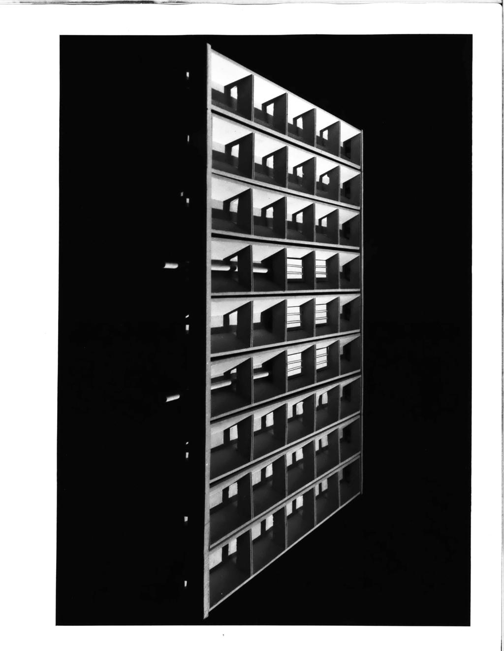
5 TABLE OF CONTENTS page Title Page I Letter of Submission ii Abstract iii Acknowledgements iv I. Introduction 1 II. Design Approach 2 III. General Description 2 A. System Selection 3 B. Module Selection 5 C. Bay Size Selection 6 D. Core Design 8 IV. Structural Elements 10 A. Beam Channel 10 B. Girder 13 C. Column 14 D. Filler Pieces 15 E. Construction Sequence 16 V. Mechanical System 17 A* General Theory 17 VI. B. Air Conditioning - Interior Zone 20 C. Air Conditioning - Exterior Zone 21 D. Lighting 21 E. Acoustics 22 Photographs of Drawings and Model
6 -1- I. INTRODUCTION Systems oriented arhictecture is in a very primitive state today. To build at large scale in a systematic manner which allows for growth and flexibility is a problem which architects have neglected. In a sense, architects have become merely stylists. Today's needs require a new vocabulary based on our technological advancements. A system of building must be developed which allows for orderly growth, interior and exterior spatial flexibility, and logical vertical and horizontal circulation patterns for occupants and mechanical services. A basic geometric unit must be established which is self sufficient structurally and mechanically. This basic unit may be combined with other similar units to meet varying building programs. Permanent elements and temporary elements within the building must be sorted out. Certain vital elements become permanent components such as cores, columns, girders, and main mechanical branches. Secondary components such as beams and secondary mechanical service branches can change or be removed to achieve flexibility in use or variety through spatial changes. These components are then considered temporary. This hierarchy of building elements permits continued use of the building long after its original intended use no longer exists. Buildings today become obsolete much before the life span of their physical shell.
7 -2- II. DESIGN APPROACH To be built in a systematic manner, architecture for educational facilities requires a dimensioned framework which is expressed graphically in plan and section. Footprints of a structure are made by its columns, cores and spanning elements. The basic design approach is to develop a wallpaper plan which shows these components. Plan variations (stimulated by varying programmatic requirements) are superimposed over this wallpaper adhering to the gramatic rules of the building system. The planning problem to be solved is that of bay size, module selection, core design and column design. Flexibility and growth patterns of lineal or one-way structural systems versus two-way structural systems are studied and evaluated. Integration of the permanent mechanical services within the structure and access to the temporary mechanical services is of primary importance. Maximum uninterrupted floor area, minimum depth of floor structure, maximum spatial variation, and simplicity in mechanical distribution and return patterns are also important design considerations. III. GENERAL DESCRIPTION A lineal, precast, prestressed reinforced concrete structural system of columns, girders and beam channels
8 -3- was developed with a poured in place leveling and topping slab. The clearspan bay size is twenty-fiv e feet by fifty feet. The planning module is five feet by ten feet. The construction depth is two feet six inches including a three inch topping slab. Modular cores containing the basic elements of fire stairs, passenger elevators, vertical mechanical shafts, freight elevators, and lavatories were developed within the fifty foot span between girders. Axial dimensions in increments of the five foot module. The mechanical system for air conditioning utilizes the space between the double girders for horizontal distribution to the channel beams. Cores provide the supply and return of air for the interior zone of the building. Columns provide the supply for the fifteen foot perimeter zone of the basic unit. The basic unit of five bays in the axial direction and three bays in the longitudinal direction is the maximum floor area for the fire stair requirements as dictated by the National Fire Code. Axial and/or longitudinal expansion is accomplished utilizing multiples of the basic unit. A. System Selection The primary system classifications are: 1. One-way or lineal 2. Two-way The most direct and commonly used framing system is
9 -4- the one-way system. Beams and major girders transfer loads to the columns. Only in the most sophisticated applications of the one-way system are both prestressing and post-tensioning performed. The prestressing carries the stresses due to dead loads; the post-tensioning carries live loads and the topping slab acts as a diaphram for structural continuity. Flexibility in mechanical service distribution is limited. The structure is directional and the distribution of the stresses in a bay is evident in the differentiation of the sizes of the members. The two-way system requires post-tensioning in two directions forming a two-way matrix. Currently this is a complex and costly operation. Post-tensioning involves the use of jacks and threading cables through a structure. Major difficulties arise in joints between members which must be over dimensioned to accomodate compressive forces due to post-tensioning. Deviations in positioning holes for post-tensioning cables requires over dimensioning the holes. Two-way systems usually make extensive use of scaffolding. Since both one way and two way systems offer degrees of spatial flexibility and growth and since feasibility is based on economic studies, a qualitative decision was made. In this thesis a one-way system was selected over a twoway structural system since preliminary studies showed interior spatial flexibility could be achieved with greater
10 -5- structural ease. Generally, less post-tensioning, less scaffolding and a lesser number of components are necessary to construct a given bay size. B. Module Selection The determinates of a good module are the result of weighing the following factors: 1. Space planning 2. Structural systems e. Mechanical systems A five foot by ten foot module was selected. This module produces a smallest habitable space of nine feet six inches by nine feet six inches (two modules minus partition dimensions) and the next largest space of nine feet six inches by fourteen feet six inches (three modules). These spaces were considered satisfactory for offices in a building for education. Satisfactory intradepartmental circulation can be accomplished in a four foot six inch space (one module). Primary circulation can be accomodated within dimensions of nine feet six inches or fourteen feet six inches. The dimensions of beams in a beam and girder precast system are a significant factor in module selection. Since the transporting of members is critical to a successful precast system, it was felt that structural members should not exceed sixty feet. It is also desirable that beam members should not be less than forty feet in length. The
11 -6- establishment of a lineal system influenced the decision in favor of a rectangular module. Spacing of luminaires and air conditioning diffusers, while somewhat more flexible than the space planning and structural systems factors, are module determinants. The use of standard length luminaires and a regular pattern of diffusers does reduce the cost of a mechanical system. A five foot by ten foot module easily accomodates two standard eight foot, forty watt fluorescent lamps in each module. This produces an even distribution of light at 100 footcandles at the three foot working surface. Two-inch wide strip diffusers located ten feet on center provide an even distribution of air for large spaces as well as small. Since the column is important to the vertical supply of the mechanical system as well as the structural system, the dimensions of the column should not only coincide with the structural module but should also provide adequate space for ducts and pipes. A five foot by five foot space provides adequately for these two functions. While other modules may more ideally meet the requirements of one or more of the above factors, the five foot by ten foot module most adequately meets all of the factors. C. Bay Size Selection Three primary factors dictated the final bay size after the five foot by ten foot module had been selected: 1. The desire to provide large spaces uninterrupted by columns for planning flexibility.
12 -7-2. The desire to have the girders flush with the beam channels and therefore eliminate a special condition when interior partitions meet the girder. 3. The desire to keep the structural depth of the floor minimal. Program requirements for education buildings, only in exceptional cases, require spaces wider than fifty feet. Exceptions to this planning factor are large auditoriums. It was felt that these could be handled as special conditions within an education complex since the requirement is unusual. A two to one ratio of length of beam channel to girder within a given bay gives a flush ceiling. Therefore, with one dimension fixed at fifty feet the clearspan for the girder becomes twenty five feet. While this limits uninterrupted floor space in the longitudinal direction, spaces can be obtained which are fifty feet wide and which have a length dictated only by the physical dimension of the entire building. The length of span in a reinforced concrete structure divided by twenty gives the depth of structure. Therefore: Beam channel: 5 ft- 2.5 ft. The structural depth of two feet six inches was found to be adequate for the passage of low velocity air conditioning ducts (maximum duct dimension with insulation being
13 -8- eight inches by twelve inches to service an area ten feet by fifty feet), the luminaires (four inches), and the acoustic panels (one inch). D. The Core Centrally located in the basic unit is the core containing all those elements which perforate a structure vertically. Primary vertical air conditioning shafts, electrical and telephone terminal boxes for each floor, passenger and freight elevator shafts, fire stairs, and rest rooms are included in this service core. The central position of the core insures equal distribution of services to all parts of the building. Developed on a module of five feet (as illustrated on the plan variation drawing) the core has four variations based on varying programmatic requirements. 1. The fire stair with five feet by fifteen feet vertical mechanical shafts on each end would be used if the structure were less than three stories high. The overall dimension is fifty feet by fifteen feet. 2. Passenger elevators, fire stairs and vertical mechanical shafts would be used if the building were four or more stories high. This core variation has an overall dimension of twenty five feet by fifty feet. 3. Freight elevator, men and women's rest rooms, passenger elevators, fire stairs and mechanical shaft are considered the typical minimum complete unit for an average five story building. The overall dimensions of this core
14 -9- variation is thirty feet by fifty feet. 4. A freight lobby, a janitor's closet, and larger rest rooms in addition to the items mentioned above are included in the fourth modular variation. This fifty five by fifty foot core can be utilized where extremely heavy usage occurs. Cores in all cases fill the entire span of fifty feet. The precast girders tie into the poured in place core walls. This tie enables the core walls to take longitudinal and axial shear. For the entire structure, general planning factors which determined the size of the cores are: 1. "Group 'D' buildings... distance of travel to nearest exit shall not exceed 150 feet from any point." (National Fire Protection Code, paragraph 2243). 2. "Fire stair width shall be a minimum of six units (one unit equals 22 inches).' This may be two scissor stairs of 3 units each as shown on the typical plan drawing. (National Fire Protection Code, paragraphs 2202, 2103, , and 2272). 3. One six foot by eight foot elevator in a five story building serves a net area of 85,000 square feet. Therefore: Total area of basic unit - number of Ara served by one -elevator elevators 4. One electrical closet has twenty square feet for every 15,000 square feet of gross area.
15 _10-5. one telephone closet has fifty square feet for every 15,000 square feet. 6. One janitor's closet has thirty square feet for every 30,000 square feet of gross area. 7. One service elevator is adequate to service two basic units (162,500 square feet each) in a five story building. 8. Plumbing section (assuming 200 people per floor): Lavatories Water closets Urinals Men women (Graphic Standards, 5th edition, p. 520, "Schools") 9. Return air shafts (low velocity fpm) require one square foot per 1,000 square feet of floor area. Supply (high velocity - 4,000 fpm) requires one square foot per 4,000 square feet of floor area. More specific formulae for vertical duct sizes is included in the section on mechanical - interior zone. IV. STRUTURAL EIEMENTS A. The Beam Channel The geometry of the beam channel is dictated by the configuration of the girder, the necessity of providing a working floor surface during construction, the space requirements for return air voids between the channels, the space requirements for the temporary air supply ducts which must
16 -11- be accessible from below, and the requirements for acoustical sound absorption panels, lighting and pipes. In addition to these basic and very functional requirements, there is an unwritten but equally important requirement for a visually pleasing ceiling. Also necessary is a continuous ceiling grid for partition abutment. In this design the diaphrams are not simply false partition abutments. They are required structurally to prevent the inclined walls of the beam channel from spreading. The diaphrams are therefore ties which bind the beam channel walls together. The length of the beam channel is fifty feet. Its width is four feet ten inches allowing a two inch void between beam channels at the ceiling plane. This void splays to a two feet six inch dimension at the floor plane where it is sealed by a precast concrete filler piece. The void is the return air duct for the air conditioning system. Since return air ducts require no insulation, the concrete of the channel beams actually form the duct. Because the configuration of the beam channel was not determined primarily by a method of forming, several methods of casting are feasible. The first and most technologically compatible method is a single monolithic cast. Form work for the channel beam consists of three elements: the coffer mold, and two symmetrical side forms. Knock out form work is placed above the diaphrams to allow the passage of supply ducts and pipes.
17 -12- Another method consists of precasting the diaphrams, precasting and pretensioning the fifty foot tension cords, positioning these elements around five coffer forms, welding the steel projecting from the precastlpieces to a wire mesh and utilizing a sprayed concrete (Gunite Method) to coplete the walls and top of the channel beam. This technique may be more complex; however, the quality of concrete for each element could be controled and those elements which work the hardest in the structure would be made of better quality concrete. If done in a large quantity, this method could prove to be the most economical. Form work in this case could be made of either steel or molded plastic. Consideration was given to the transporting of the channel girders after casting at a central plant. The length of fifty feet was considered a feasible length for loading and transporting. The calculated weight of one beam channel is twelve kips. Five beam channels could be transported by one truck simultaneously and still be within thirty ton road weight limits. The cantilever of the beam channel may be either ten feet or fifteen feet. This cantilever must always be backed by a standard fifty foot beam channel. Scaffolding is required to position the cantilevered, precast beam channel before it is tied to the backing beam channel. This tie is accomplished by post tensioning. A Ryerson unbonded tendon post tensioning technique is utilized. The tendon is thirty
18 -13- feet long in the case of the fifteen foot cantilever and twenty five feet long in the case of the ten foot cantilever. The post tensioning process is accomplished from above utilizing the working surface of the channel beams and the filler piece over the girder. The cable is passed through a pipe which is cast in the beam channel. Adequate space is available for the hydraulic Jack required, the dimensions of which are six and one half inches in diameter and forty six inches in length. B. The Girder Two girder lengths are provided within the system. To facilitate a cantilever at the exterior edge of the structure and to facilitate multi-story voids within the structure, the primary girder was given a length of fifty five feet. Secondary girders bridge the gap between the cantilevers of the primary girders. The clearspan between columns of twenty five feet dictated the structural depth of two feet six inches. A beam cross section one foot wide and one foot six inches deep is sufficient to carry the dead load of the structure. Reinforcing steel is tied to the steel of the topping slab to increase the effective girder depth to two feet six inches. This increase in effective girder depth allows the girder to carry the total dead and live loads. The total load is two hundred pounds per square foot. Concrete trapezoidal transition projections encase
19 -14- the girder-to-slab steel ties. This vertical girder projection acts also as a guide for the placing of the beam channel. Voids between the vertical concrete projections on the girder allow duct work, pipes, wiring and communications equipment to pass over the girder and under filler pieces and leveling slab. The girders would be cast on their sides. Since the girders are flush with the bottom of the beam channels only the bottom of the girder is visible. The weight of the fity five foot long girder is 14.8 kips and the weight of the fifteen foot long girder is 4.6 kips. Truck transporting of these elements is feasible. C. The Column The column is so designed that one, two and three story heights can be cast at the factory and transported to the site. The reinforcing is varied to meet these particular height requirements. This vertical spatial flexibility does not create a special condition within the structure since girders and channel beams are merely omitted. The column is tied to the girder by post-tensioning. Grooves are cast in the column so that the one inch steel cable is visible and accessible during construction. The grooves are grouted after the columns and girders are bound together to meet fireproofing codes. A reveal one half inch deep and two and one half inches wide running the entire length of the column is the final visual product. Steel angles forming
20 -15- a box are cast into the top of the column. Grout and leveling shims are placed in this box prior to the positioning of the girder. A one inch set back is visible at the top of the column. The column dimensions are one foot by five feet in plan. Whether the columns are precast or cast "in situ" is not critical to the design solution. However, it is felt that there is some advantage to a totally precast system which is shipped to the site and wet concrete used on the site for grouting and leveling slabs. D. Filler Pieces Within this structural system there are three precast filler pieces required, 1. Beam channel fillers 2. Girder fillers 5. Transverse compression bars between girders The beam channel filler pieces are designed as small light-weight panels which bridge the two foot six inch gap between the top surfaces of the beam channel. The dimensions of the piece are one foot by two feet six inches by one inch. Weighing only thirty pounds, each piece is easily put in place by a workman on the site. These filler pieces serve only as a base for the topping slab and are not structural. Girder fillers are similar, not structural and serve as a base for the leveling and topping slab. Two sizes are
21 required: panels five feet by ten feet by two inches and panels five feet by five feet by two inches. Grooves in these pieces assist workmen on the site positioning steel in the topping slab. The weight of these pieces is.63 kips and.315 kips respectively. Structural transverse compression members are required between the girders where there is a cantilever in the beam channel. Eight inches by eight inches by three feet are the dimensions of these pieces which are bolted in place after the girders are placed. E. THE CONSTRUCTION SEQUENCE l. Footings and basement floor are poured. 2. Core walls are poured to first floor. Columns are positioned and secured to footings. 3. Girders are placed on the grouted columns and bonded. 4. Beam channels are positioned on the girders. 5. Filler pieces are placed on the beam channels and girders. 6. Transverse compression pieces are bolted in place. 7. Electrical bus ducts are layed on precast floor surface. Leveling slab steel is placed and the leveling slab is poured. 8. Columns are positioned for the next floor and steps 2 through 7 are repeated. 9. Exterior walls are set in. Mechanical duct work, electrical wiring, lighting, acoustic treatment, piping,
22 -17- and interior partitions are installed, thereby finishing the space. V. MECHANICAL SYSTEM A. General Theory The technology of mechanical systems is changing rapidly. For complete climate control, windows are fixed and the building is sealed. Air conditioning provides heating, cooling, ventilation, and humidity control. The trend is toward smaller, less conspicuous, more efficient duct work and diffusers. A typical floor in a building has two general zones of air conditioning: an interior zone and an exterior zone. Air conditioning in the interior zone is fairly constant while the exterior zone acts as the shock absorber for solar heat gain through the glass. The north side of a building has :Ar less heat gain than the south side. and west orientations vary with the time of day. the exterior zone must have more points of thermostat East Therefore, control. The exterior zone is generally considered to extend fifteen to twenty feet from the exterior wall into the building. Two separate systems are required to properly air condition a building. zones are: Air conditioning systems available today for interior 1. Low velocity - single duct a. With same temperature all over, no individual control
23 -18- b. With heat coils at diffusers to create individually controlled temperature zones 2. High velocity - single duct a. With low velocity transition box and sound attenuation at diffuser, same temperature all over b. Wlith transition box and sound attenuation to change high velocity to low velocity at point of transition in ducts from primary to secondary and coils at diffusers to provide individual temperature control 3. High velocity - dual duct (one hot, one cold) Mixing boxes and sound attenuators required to change to low velocity and provide individual temperature control. Air conditioning systems in comon use today for the exterior zone are: 1. Perimeter induction units Utilizes high velocity air with pipes carrying hot and cold supply and return water 2. Dual duct high velocity With mixing boxes at sill or ceiling
24 Fan coil units a. Utilizing pipes containing hot and cold water at sill level, plus holes in the exterior face for fresh air intake b. Utilizing pipes containing hot and cold water at sill level plus recirculation of air from the perimeter zone Calculations for duct sizes are based on high velocity air at 4000 fpm to 5000 fpm and low velocity at 1200 fpm. Low velocity return air is considered at 700 fpm. Return air is generally 75% of the supply. Toilette exhaust is calculated at twelve air changes per hour at 1000 fpm. Rules of thumb for calculating duct sizes: 1. High velocity (4000 fpm) a. Cold air -.38 sq ft duct area/l0,000 cu ft b. Hot air -.28 sq ft duct area/10,000 cu ft 2. Low velocity (1200 fpm) 1.25 sq ft duct area/10,000 cu ft 3. Return air (700 fpm) 1.5 sq ft duct area/10,000 cu ft In this thesis the primary mechanical equipment is located on the roof above the cores. Fresh air intake grills and heating and cooling equipment are also located in this penthouse., A mechanical bridge links the columns feeding the perimeter system to the core penthouse. Since the
25 cross-sectional area of the columns diminishes at the upper levels more space is available for larger ducts which feed down. A high velocity-dual duct system is used through the building for primary distribution. Electrical and telephone service originate from electrical closets in the service cores at each floor. Distribution conduits are layed in a five foot grid on the precast floor system prior to the pouring of the three inch topping slab. Terminals flush with the finished floor may be tapped as required; thus every space has flexibility in location of recepticals, telephones and intra-building communication systems. B. Air Conditioning - Interior Zone Cores provide the vertical duct space for the interior zone. The eight foot wide space between the girders flanking either side of the core contains the primary horizontal ducts. A dual duct system is used to this point. Velocity reducing, sound attenuating mixing boxes are located ten feet on center at the ends of alternating channel beams. Low velocity air is fed through alternating channel beams with strip diffusers ten feet on center throughout the space. When the space is two stories high supply ducts are placed in each channel beam with strip diffusers five feet on center throughout the space.
26 -21- C. Air Conditioning - Exterior Zone Columns provide the vertical high velocity dual duct space for the axial exterior zones. Cores provide the vertical high velocity dual duct space for the transverse exterior zones. Extensions are made to the dual ducts located between the girders adjacent to the cores. Sound attenuating, velocity reducing mixing boxes are located ten feet on center in both axial and transverse perimeter zones. Conversion from exterior to interior zone in the event of building expansion is easily accomplished. Since the primary vertical and horizontal ducts are fixed, and the sound attenuating, velocity reducing mixing boxes are located ten feet on center at the ends of the new channel beams, all that remains to be done is connect the new low velocity ducts located in the new channel beams to the mixing boxes. D. Lighting With a standard ceiling height of twelve feet for classrooms, two eight foot fluorescent tubes located in each five foot by ten foot module provide 100 foot candles of light at the working surface which is three feet above the floor. When a two story space occurs additional fluorescent tubes would be added. Space within the coffer allows for up to four fluorescent tubes per coffer. High output tubes could be utilized to increase lighting levels.
27 -22- Since the tubes are recessed within the coffer one foot three inches, only those tubes which are directly over head and those two coffers ahead of the viewer are visible. Beyond this point only the lighted plane of the concrete coffer is visible. E. Acoustics When the structure is expressed in a reinforced concrete building, acoustical treatment must be included in the design concept. In this thesis sound absorptive material is placed in the ceiling coffers above the fluorescent tubes. The acoustic panels are one foot six inches above the bottom edge of the channel beam and have an overall dimension of nine feet six inches by three feet. The effective area is only twenty four square feet due to the fact that the strip diffusers occupy a space of two inches by nine feet six inches. The reverberation time is calculated by Sabines' formula: R.T. -' where R. T. - Reverberation time in seconds V = Volume of the space in cubic feet a = Sun of the surface areas within the space multiplied times their coefficients of absorption or (a = S oo) For the smallest inhabitable space of nine feet six inches square with a twelve foot ceiling V x 9.5' x 12' fot
28 -23- Coefficient of S(area Surface Material Absorption in ft 2 Walls 3 - concrete block glass Floor terrazzo Ceiling 4 - concrete coffers acoustic panels R W sees A reverberation time of.6 secs is desirable for an office space where speech intelligibility is the primary concern. Since reverberation time in large spaces varies directly with the volume of the space and inversely with the amount of sound absorptive material, the range of reverberation for these spaces is.6 secs to 1.4 sees. This range is desirable for speech in the middle frequency range of five hundred cycles per second. Noise reduction through six inch concrete block partitions is forty decibels which is considered sufficient for educational facilities. Sound transmission is impeded in the transverse direction of the beam channel by the diaphrams. Sound absorbing acoustic baffels are placed in the return air structural voids as required.

29 nnnnnnnnnnnnnnnnnnnnnn illnnhill nnininininnnnnnninnnnhillnnn11 nnnnnin11 nnnin.n.nn.n.n.in.n.n.n.n..n.n.nn.n.inn. I IF 1 MbbltLO 1 li tb I liib I I I I PLAN VARIATIONS A PROTOTYPE SYSTEM OF BUILDING FOR EDUCATION MASTER IN ARCHITECTURE THESIS D. L. PAVELKA M.. T. 1966

30 ...!.!.!..!.!!!!...!...n..n n..nn nnn.. nn... n...!!.. n. nn.. n.nn..... n...n... n.n... SECTION VARIATIONS A PROTOTYPE SYSTEM OF BUILDING FOR EDUCATION MASTER IN ARCHITECTURE THESIS D. L. PAVELKA M.I.T. 1966
![I l l 1 11 I od I D O OL 1111111 H I nnnim If RH OI -ThY VI uinirn1ruu1- IW1WBWIHiTfliIl]IHIT1 flflbhfu1b IL][]P LIGHTING ARCH I II zlz zbifi II II II iit'ibhfz] _ u I= I = _ n I I I II](/docs-images/88/117934329/images/31-0.jpg "111111111I11111111.111111 1. 1 T-- o*ei c LI]EslZIo ~ REFLECTED CEILING PLAN MECH TYPICAL FLOOR PLAN A PROTOTYPE SYSTEM OF BUILDING FOR EDUCATION 0 5 10 20 30 s MASTER IN ARCHITECTURE THESIS D. L. PAVELKA M.")
31 I l l 1 11 I od I D O OL H I nnnim If RH OI -ThY VI uinirn1ruu1- IW1WBWIHiTfliIl]IHIT1 flflbhfu1b IL][]P LIGHTING ARCH I II zlz zbifi II II II iit'ibhfz] _ u I= I = _ n I I I II I T-- o*ei c LI]EslZIo ~ REFLECTED CEILING PLAN MECH TYPICAL FLOOR PLAN A PROTOTYPE SYSTEM OF BUILDING FOR EDUCATION s MASTER IN ARCHITECTURE THESIS D. L. PAVELKA M.I.T 1966
32 STRUCTURAL ISOMETRIC A PROTOTYPE SYSTEM OF BUILDING FOR EDUCATION 0 I MASTER IN ARCHITECTURE THESIS DLPAVELKA MIT. t1966
33 GIRDER REINFORCING CHANNEL REINFORCING FILLER PANELS & TOPPING SLAB doubt. duct high.iaoity electrical conduits in slab 5' me. AXIAL SECTION A PROTOTYPE SYSTEM OF BUILDING FOR EDUCATION E MASTER IN ARCHITECTURE THESIS D. L. PAVELKA M.I. T. 1966
34 CHANNEL REINFORCING CHANNEL CANTILEVER FILLER PANELS & TOPPING SLAB MECHANICAL LONGITUDINAL SECTION A PROTOTYPE SYSTEM OF BUILDING FOR EDUCATION MASTER IN ARCHITECTURE THESIS D. L. PAVELKA M.I.T. 1966

35 I~7.-,-, 7 ELEVATION A PROTOTYPE SYSTEM OF BUILDING FOR EDUCATION MASTER IN ARCHITECTURE THESIS L L. PAVELKA M.L T. r19
36

37

38

39

40
41
1 / Submitted in partial fulfillment of the requirements for the degree of Master in Architecture at the Massachusetts Institute of Technology
 1 / / Ni. ~ P A N S L A B C O N S T R U C T IO N F O R I N T E G R A T E D M E C H A N I C A L S Y S T E M S Submitted in partial fulfillment of the requirements for the degree of Master in Architecture
June, 1966 BUILDING AS A SYSTEM. HUGO GARCIA-PEREZ B. Arch., University of Mexico SUBMITTED IN PARTIAL FULFILLMENT
 {.OCT 6 ~1966 BUILDING AS A SYSTEM by HUGO GARCIA-PEREZ B. Arch., University of Mexico SUBMITTED IN PARTIAL FULFILLMENT OF THE REQUIREMENTS FOR THE DEGREE OF MASTER OF ARCHITECTURE at the MASSACHUSETTS
THE FORENSIC MEDICAL CENTER
 THE FORENSIC MEDICAL CENTER Image courtesy of Gaudreau, Inc. TECHNICAL REPORT #2 OCTOBER 26, 2007 KEENAN YOHE STRUCTURAL OPTION DR. MEMARI FACULTY ADVISOR EXECUTIVE SUMMARY Image courtesy of Gaudreau,
Brent Ellmann Structural Option 200 Minuteman Park, Andover, MA Structural Consultant: Dr. Hanagan
 Brief Building Overview: 200 Minuteman Park stands as a 200,000 square foot Class A office building in Andover, Massachusetts, worth roughly $15,000,000. Although the building has a large square footage,
VARIOUS TYPES OF SLABS
 VARIOUS TYPES OF SLABS 1 CHOICE OF TYPE OF SLAB FLOOR The choice of type of slab for a particular floor depends on many factors. Economy of construction is obviously an important consideration, but this
STEEL STRUCTURAL SYSTEMS
 STEEL STRUCTURAL SYSTEMS Steel elements are of two basic types: Structural steel shapes are formed into their final shapes by hot-rolling. This method produces such common elements as wide flange sections,
Simplified Building Schematic for Typical Floor (Levels 9 through 22):
:") Introduction to Structural System Simplified Building Schematic for Typical Floor (Levels 9 through 22): Key: - Tower Columns - Tower Shear Walls - Parking Garage Columns - Parking Garage Shear Walls Solid
Introduction to Structural System Simplified Building Schematic for Typical Floor (Levels 9 through 22): Key: - Tower Columns - Tower Shear Walls - Parking Garage Columns - Parking Garage Shear Walls Solid
Crossroads at Westfields Building II
 Crossroads at Westfields Building II Chantilly, Va STEPHEN LUMPP Structural option Faculty Consultant: Dr. Andres Lepage Technical Report 2 EXECUTIVE SUMMARY This report is a study of alternate floor systems
one structural behavior, systems, and design ARCHITECTURAL STRUCTURES: FORM, BEHAVIOR, AND DESIGN DR. ANNE NICHOLS SUMMER 2015 lecture
 ARCHITECTURAL STRUCTURES: FORM, BEHAVIOR, AND DESIGN DR. ANNE NICHOLS SUMMER 2015 lecture one structural behavior, systems, and design Introduction 1 www.greatbuildings.com Syllabus & Student Understandings
one structural behavior, systems and design Course Description Course Description Syllabus & Student Understandings statics mechanics of materials
 ARCHITECTURAL STRUCTURES: FORM, BEHAVIOR, AND DESIGN DR. ANNE NICHOLS SUMMER 2014 lecture one Syllabus & Student Understandings structural behavior, systems and design Introduction 1 Architectural Structures
Technical Report #2 10/26/06
 Photo courtesy of OTO Development, http://www.otodevelopment.com/ Dr. Memari Thesis Advisor Technical Report #2 10/26/06 Executive Summary Systems Overview Hollow Core Plank (precast) Solid Flat Slab (precast)
The building on 250 West Street is a 7-story multi-use that provides space for parking,
 December 5, 2002 Thesis Executive Summary The proposal for the investigation of the building on 250 West Street will include an in depth look at the floor and lateral systems. A continuation of the Pro-Con
Table of Contents.2. Introduction...3 Gravity Loading and Deflections..4. Existing Structural System..8
 WISCONSIN PLACE RESIDENTIAL TECHNICAL ASSIGNMENT 2 OCTOBER 29, 2007 KURT KRASAVAGE THE PENNSYLVANIA STATE UNIVERSITY STRUCTURAL OPTION FACULTY ADVISOR: DR. ALI MEMARI 1 Table of Contents Table of Contents.2
Structural Technical Report #2 Pro/Con Study of Alternate Floor Systems
 Christopher McCune Structural Option Eight Tower Bridge Faculty Advisor: Dr. Hanagan October 31 st, 2005 Structural Technical Report #2 Pro/Con Study of Alternate Floor Systems Executive Summary This technical
Jonathan R. Torch Technical Report 2 Columbia University. Technical Report 2. Pro-Con Structural Study of Alternate Floor Systems
 Technical Report 2 Pro-Con Structural Study of Alternate Floor Systems Columbia University Broadway & 120 th Street, New York, NY Jonathan R. Torch Pennsylvania State University Architectural Engineering
Structural Technical Report 1 Structural Concepts / Structural Existing Conditions Report
 Michael A. Troxell Structural Option Advisor: Professor Parfitt College of Business Administration Oct. 5, 2005 Structural Technical Report 1 Structural Concepts / Structural Existing Conditions Report
two structural systems, planning and design Structural Organization Bearing Walls Structural Components
 ARCHITECTURAL STRUCTURES: FORM, BEHAVIOR, AND DESIGN DR. ANNE NICHOLS FALL 2013 lecture two structural systems, planning and design AISC teaching aids: Courtesy of John Hooper, MKA Seattle Structural Organization
two structural systems, planning and design Structural Organization Structural Components Bearing Walls
 ARCHITECTURAL STRUCTURES: FORM, BEHAVIOR, AND DESIGN DR. ANNE NICHOLS FALL 2017 lecture two structural systems, planning and design AISC teaching aids: Courtesy of John Hooper, MKA Seattle Structural Organization
Office Building-G. Thesis Proposal. Carl Hubben. Structural Option. Advisor: Dr. Ali Memari
 Office Building-G Thesis Proposal Structural Option December 10, 2010 Table of Contents Executive Summary... 3 Introduction... 4 Gravity System...4 Lateral System:...6 Foundation System:...6 Problem Statement...
North Mountain IMS Medical Office Building
 North Mountain IMS Medical Office Building Phoenix, Arizona Michael Hopple Technical Assignment 1 October 5 th, 2007 AE 481W-Senior Thesis The Pennsylvania State University Faculty Adviser: Dr. Ali Memari,
Temecula Medical Center Temecula, CA
 Temecula Medical Center Temecula, CA Technical Assignment #2 Sean F. Beville The Pennsylvania State University Architectural Engineering Structural Option Senior Thesis Project Student Advisor: Thomas
The New Incremental Launching Construction Technology of Jiubao Bridge Long-span Hybrid Arch-girder Structure
 The New Incremental Launching Construction Technology of Jiubao Bridge Long-span Hybrid Arch-girder Structure C.Y. Shao Shanghai Municipal Engineering Design & Research General Institute (Group) Co. Ltd.,
ORDINANCE NO BE IT ORDAINED BY THE CITY COUNCIL OF THE CITY OF BOULDER, COLORADO: CHAPTER 98 - Baled Straw Structures SECTION PURPOSE
 ORDINANCE NO. 5891 AN ORDINANCE AMENDING CHAPTER 10-5, B.R.C. 1981, CONCERNING ALTERNATIVE BUILDING MATERIALS, INCLUDING ADOBE AND STRAW BALE CONSTRUCTION AND RECYCLED LUMBER. BE IT ORDAINED BY THE CITY
OVERALL STRUCTURAL SYSTEM
 EXECUTIVE SUMMARY The at the Pittsburgh International Airport, PA, is a 275,000 square foot multi-use building located directly adjacent to the airport s landside terminal. The building consists of an
fourteen Structural Planning 1 APPLIED ACHITECTURAL STRUCTURES: DR. ANNE NICHOLS SPRING 2019 lecture STRUCTURAL ANALYSIS AND SYSTEMS ARCH 631
 APPLIED ACHITECTURAL STRUCTURES: STRUCTURAL ANALYSIS AND SYSTEMS DR. ANNE NICHOLS SPRING 2019 lecture fourteen structural planning Structural Planning 1 Structural Design Sequences first-order design structural
Structural Inspection
 General: Background: An inspection and structural analysis have been performed for the purpose of evaluating the buildings structural systems and components. A full set of structural drawings was utilized
BUILDING DESCRIPTION
 BUILDING DESCRIPTION ARCHITECTURAL ENGINEERING SENIOR THESIS 1 Building Description Location: The Residences of Sherman Plaza are located in the diverse community of downtown Evanston, IL, just north of
Thesis Proposal 12/13/06
 Photo courtesy of OTO Development, http://www.otodevelopment.com/ Dr. Memari Thesis Advisor Thesis Proposal 12/13/06 Executive Summary Structural System The in, is an eleven story hotel complex which reaches
David A. Walenga Technical Assignment #1
 Executive Summary Contained in this report is design information related to the structural system of the Residence Inn by Marriot located in Stamford, Connecticut. Specifically, this report covers: code
Atkinson Engineering, Inc.
 Atkinson Engineering, Inc. Atkinson Engineering, Inc. One of the problems in underpinning a typical post-tensioned foundation is support for the slab part that spans between the stiffening beams. An example
Third Avenue New York, NY. Structural Concepts/ Structural Existing Conditions Report September 30, Michelle L.
 Executive Summary The structural design of 554-556 Third Avenue is composed of two way concrete slabs supported by a system of columns spanning an average of twenty feet. Lateral loads are resisted by
1. Cast-in-place concrete is specified in Section
 SECTION 03 38 00 PART 1 - GENERAL 1.01 DESCRIPTION A. This Section describes the requirements for furnishing and installing post-tensioned slabs, jacks, jacking and anchors at Parking Structure, and record
Structural Option Indiana Regional Medical Center Indiana, PA
 West View of IRMC Southeast View of IRMC Structural Option Indiana Regional Medical Center Indiana, PA West View of IRMC Southeast View of IRMC Arial View of IRMC Project Information N Location: Occupancy
Overall Existing Conditions Summary
 September 12, 2002 Overall Executive Summary: The multi-use project on 250 West Street is a 7-story building with space for offices, retail, storage and parking. The project is a small part of the development
North Mountain IMS Medical Office Building
 North Mountain IMS Medical Office Building Phoenix, Arizona Michael Hopple Technical Assignment 2 October 29 th, 2007 AE 481W-Senior Thesis The Pennsylvania State University Faculty Adviser: Dr. Ali Memari,
Union County Vocational - Technical Schools Scotch Plains, New Jersey
 SECTION 092216 - NON-STRUCTURAL METAL FRAMING PART 1 - GENERAL 1.1 RELATED DOCUMENTS A. Drawings and general provisions of the Contract, including General and Supplementary Conditions and Division 01 Specification
City of Westerville Guide to Commercial Inspections
 City of Westerville Guide to Commercial Inspections FOOTINGS - After the excavation, with the form work and any required reinforcing steel in place. All footings shall have loose soil removed, reinforcing
Regulations of Connecticut State Agencies
 This document was prepared by the Connecticut State Library and is provided for the convenience of the reader. This is not the official version of the regulations. The official regulations are published
Bonner Bridge Replacement Update:
 Bonner Bridge Replacement Update: Jerry D. Jennings, PE - NCDOT Division 1 Engineer Pablo A. Hernandez, - NCDOT Resident Engineer September 18, 2017 Bonner Bridge Replacement Timeline Refresher Bonner
Brent Ellmann Structural Option 200 Minuteman Park, Andover, MA Structural Consultant: Dr. Hanagan
 Executive Summary: 200 Minuteman Park currently stands as a three story commercial building. The original design was limited to three stories by an industrial zoning law in Andover, Massachusetts. If this
151 First Side. Technical Assignment 2 November 16 th, William J. Buchko. AE 481w Senior Thesis The Pennsylvania State University
 November 16 th, 2007 William J. Buchko AE 481w Senior Thesis The Pennsylvania State University Thesis Advisor: Kevin Parfitt Table of Contents Executive Summary... 3 Structural System Overview Foundation...
Dead Loads (psf): Concrete Floor Slab on Metal Deck 45 psf Mechanical and Ceiling 7 psf Miscellaneous 5 psf Exterior Wall 80 psf
: Concrete Floor Slab on Metal Deck 45 psf Mechanical and Ceiling 7 psf Miscellaneous 5 psf Exterior Wall 80 psf") CODES AND REQUIREMENTS The structural design of Northbrook Corporate Center was based on the International Building Code 2003, which incorporates many of the provisions of ASCE 7. The lateral load design
CODES AND REQUIREMENTS The structural design of Northbrook Corporate Center was based on the International Building Code 2003, which incorporates many of the provisions of ASCE 7. The lateral load design
Alexis Pacella Structural Option Dr. Schneider Lexington II, Washington D.C. Technical Report #2 October 31,
 1 Executive Summary: Pro-Con Structural Study of Alternate Floor Systems is an investigation into possible alternative structural systems for Lexington II in Washington, D.C. For this report, several structural
ADAPT-PT 2010 Tutorial Idealization of Design Strip in ADAPT-PT
 ADAPT-PT 2010 Tutorial Idealization of Design Strip in ADAPT-PT Update: April 2010 Copyright ADAPT Corporation all rights reserved ADAPT-PT 2010-Tutorial- 1 Main Toolbar Menu Bar View Toolbar Structure
Statement of Special Inspections
 Statement of Special Inspections SUCF Project No: Project Title: Registered Design Professionals in Responsible Charge: (Name) (Address) Architect: Structural Engineer: Mechanical Engineer: Identification
Structural Technical Report I October 5, 2006 Structural Concepts / Structural Existing Conditions Report
 1 THE ODYSSEY ARLINGTON, VA Aaron Snyder Structural Option Advisor: M. Kevin Parfitt, PE Structural Technical Report I October 5, 2006 Structural Concepts / Structural Existing Conditions Report Executive
Kaleida Health Global Heart and Vascular Institute University at Buffalo CTRC/Incubator. Buffalo, New York. Technical Report #2
 University at Buffalo CTRC/Incubator Buffalo, New York William McDevitt October 27, 2010 Table of Contents Executive Summary...3 Introduction...4 Structural System Overview...5 Foundation...5 Floor System...5
SJI Updates Expanded Load Tables for Noncomposite Joists / Joist Girders and Development of New Composite Joist Series
 SJI Updates Expanded Load Tables for Noncomposite Joists / Joist Girders and Development of New Composite Joist Series SUMMARY David Samuelson Steel joists are growing in recognition as being a very economical
Section G1. Design of Cast-In-Place Box Conduits
 G1-1 Economy of Design 1. Height to Width Ratio Section G1 Design of Cast-In-Place Box Conduits Careful economic studies should be made to determine the greatest economy of the entire storm drain. As an
Structural Technical Report 1 Structural Concepts / Existing Conditions
 Chris Shelow Structural Advisor: M. Kevin Parfitt Koshland Integrated Natural Science Center 10/05/05 AE 481W Structural Technical Report 1 Structural Concepts / Existing Conditions Executive Summary The
Nortrax Section David Manchester Road, Ottawa NON-STRUCTURAL METAL FRAMING 16 May 2014 Page 1
 16 May 2014 Page 1 PART 1 GENERAL 1.1 DESCRIPTION This section specifies steel studs wall systems, shaft wall systems, ceiling or soffit suspended or furred framing, wall furring, fasteners, and accessories
Concrete Prestressed Concrete Pretensioned Concrete Posttensioned Concrete Typical Tendon Layout
 Concrete 45 1.13.0 Prestressed Concrete Concrete in which internal stresses (forces) are induced by means of prestressing steel tendons such that tensile stresses resulting from loads are counteracted
200 Minuteman Drive. New Design for Additional Floors and Vibration Sensitive Equipment. Brent Ellmann. Structural Option
 200 Minuteman Drive New Design for Additional Floors and Vibration Sensitive Equipment Brent Ellmann Structural Option Dr. Linda Hanagan - Consultant Project Players Owner- Brickstone Properties Architects-Burt
THE FORENSIC MEDICAL CENTER
 THE FORENSIC MEDICAL CENTER Image courtesy of Gaudreau, Inc. TECHNICAL REPORT #1 OCTOBER 5, 2007 KEENAN YOHE STRUCTURAL OPTION DR. MEMARI FACULTY ADVISOR EXECUTIVE SUMMARY Image courtesy of Gaudreau, Inc.
Structural Technical Report 1 Structural Concepts/ Structural Existing Conditions Report
 Kelly M. Sadusky The Food Science Building Oct. 6, 2004 Professor Parfitt University Park, PA Structural Option Executive Summery: Structural Technical Report 1 Structural Concepts/ Structural Existing
Investigation for the Removal of Steel Tie Rods in a Historic Segmental Arch Floor
 Investigation for the Removal of Steel Tie Rods in a Historic Segmental Arch Floor J. Lan 1, R. Gilsanz 2, and M. Lo 3 1 Gilsanz Murray Steficek, LLP, 129 West 27 th St., 5 th Floor, New York, NY 10001
Best Buy Corporate Building D (4) Richfield, MN
 Richfield, MN") Best Buy Corporate Building D (4) Thesis Proposal Professor Boothby December 12 th, 2008 Executive Summary: The Best Buy Corporate Building D is a 6 story building with a total area of 304,610 square feet.
Best Buy Corporate Building D (4) Thesis Proposal Professor Boothby December 12 th, 2008 Executive Summary: The Best Buy Corporate Building D is a 6 story building with a total area of 304,610 square feet.
SECTION TILT-UP PRECAST CONCRETE SANDWICH PANELS. A. Work includes, but is not limited to, the following:
 PART 1 GENERAL 1.01 SUMMARY SECTION 03460 TILT-UP PRECAST CONCRETE SANDWICH PANELS A. Work includes, but is not limited to, the following: 1. Architectural precast concrete sandwich wall panels. 2. Integral
BROCHURE # 108 CONSTRUCTION PLAN COMPONENTS
 BROCHURE # 108 CONSTRUCTION PLAN COMPONENTS Please note: This construction plan component list is to be used as a guide to assist you with your project. There may be elements unique to your project not
Technical Assignment 3 December 3, 2007
 Technical Assignment 3 December 3, 2007 101 Eola Drive, Orlando, FL Justin Raducha Pennsylvania State University Faculty Advisor: M. Kevin Parfitt Table of Contents Table of Contents... 2 Executive Summary...
SECTION NON-STRUCTURAL METAL FRAMING
 SECTION 09 22 16 PART 1 - GENERAL 1.1 DESCRIPTION A. This section specifies steel studs wall systems, shaft wall systems, ceiling or soffit suspended or furred framing, wall furring, fasteners, and accessories
Brent Ellmann Structural Option 200 Minuteman Park, Andover, MA Structural Consultant: Dr. Hanagan
 Structural Design: Goals: The original design of 200 Minuteman Drive was dictated largely by Brickstone Properties, the building s owner. The new design of 200 Minuteman Drive, with additional floors,
TECHNICAL REPORT 1. Structural Concepts / Structural Existing Conditions. Penn State Hershey Medical Center Children s Hospital. Hershey, Pennsylvania
 TECHNICAL REPORT 1 Structural Concepts / Structural Existing Conditions Penn State Hershey Medical Center Children s Hospital Matthew V Vandersall The Pennsylvania State University Architectural Engineering
ADAPT-PTRC 2016 Getting Started Tutorial ADAPT-PT mode
 ADAPT-PTRC 2016 Getting Started Tutorial ADAPT-PT mode Update: August 2016 Copyright ADAPT Corporation all rights reserved ADAPT-PT/RC 2016-Tutorial- 1 This ADAPT-PTRC 2016 Getting Started Tutorial is
Marina Bay Sands Hotel Arch 631 Kayla Brittany Maria Michelle
 Marina Bay Sands Hotel Arch 631 Kayla Brittany Maria Michelle Overall Information Location: Singapore Date of Completion: 2010 Cost: $5.7 billion Architect: Moshe Safdie Executive Architect: Aedas, Pte
OCT F TO E BUILDINGS AS SYSTEMS SUBMITTED IN PARTIAL FULFILLMENT OF THE REQUIREIENTS FOR THE DEGREE OF MASTER OF ARCHITECTURE AT
 0.0F TO E OCT 6 1966 BUILDINGS AS SYSTEMS SUBMITTED IN PARTIAL FULFILLMENT OF THE REQUIREIENTS FOR THE DEGREE OF MASTER OF ARCHITECTURE AT THE MASSACHUSETTS INSTITUTE OF TECHNOLOGY A /) PAUL SUN B.A. TARKIO
TECHNICAL SPECIFICATION
 TECHNICAL SPECIFICATION ITEM 03100 CONCRETE FORMWORK 1.0 GENERAL 1.1 DESCRIPTION This section defines requirements and limitations for design, construction, erection, and removal of concrete formwork for
Danielle Shetler - Structural option Courtyard by Marriott Lancaster, PA
 Structural Analysis Overview: During the structural analysis of the in Lancaster, Pa, a redesign of the lateral and gravity system from masonry bearing and shear walls to a staggered truss system was performed.
SPECIAL SPECIFICATION 4584 Segmental Concrete Bridge Unit
 2004 Specifications CSJ: 0028-09-111 SPECIAL SPECIFICATION 4584 Segmental Concrete Bridge Unit 1. Description. Construct cast-in-place segmental concrete box girder superstructure according to the plans,
FDA OC/ORA Office Building
 FDA OC/ORA Office Building Table of Contents Executive Summary... 3 Introduction... 4 Structural System... 5 Foundation:... 5 Floor System:... 7 Building 31:... 7 Building 32:... 9 Columns... 10 Lateral
1000 CONNECTICUT AVENUE
 1000 CONNECTICUT AVENUE Gea Johnson Structural Option Faculty Advisor: Dr. Hanagan September 23, 2011 Revised: December 16, 2011 Washington DC Technical : Existing Conditions Table of Contents Executive
TILT-UP PRECAST CONCRETE SANDWICH PANELS. A. Work includes, but is not limited to, the following:
 PART 1 GENERAL 1.01 SUMMARY SECTION 03460 TILT-UP PRECAST CONCRETE SANDWICH PANELS A. Work includes, but is not limited to, the following: 1. Architectural precast concrete sandwich wall panels. 2. Integral
January 14, 2006 Structural Thesis Proposal: Structural and Breadth Redesign Options
 River Tower at Christina Landing Wilmington, DE Joseph Bednarz Structural Option Faculty Advisor: Dr. Boothby Executive Summary January 14, 2006 Structural Thesis Proposal: Structural and Breadth Redesign
ESCONDIDO FIRE DEPT TRAINING MANUAL Section Truck Module Page 1 of 7 High Rise Anatomy Revised
 Truck Module Page 1 of 7 HIGH RISE BUILDING CONSTRUCTION The Truck Module 1000.00 sections are designed to be companion documents to EOM section 503.00 Objectives The objective of this section is to provide
Requirements for Measuring and Pricing of Structural Concrete
 Requirements for Measuring and Pricing of Structural Concrete October 2016 TRANSPORT INFRASTRUCTURE IRELAND (TII) PUBLICATIONS About TII Transport Infrastructure Ireland (TII) is responsible for managing
Letter of Transmittal
 Letter of Transmittal November 17, 2014 Ali Said Structural Thesis Advisor The Pennsylvania State University aus59@psu.edu Dear Doctor Said, The following technical report fulfills the fourth Technical
Anchor bolts ASTM F1554, Gr. 36 Wide flange beams ASTM A992, Fy = 50 ksi Misc. structural steel ASTM A36, Fy = 36 ksi
 STRUCTURAL NOTES MATERIAL STRENGTHS Structural Steel Reinforcing Steel Concrete Masonry Structural Lumber Anchor bolts ASTM F1554, Gr. 36 Wide flange beams ASTM A992, Fy = 50 ksi Misc. structural steel
SPECIAL INSPECTION AGREEMENT
 PART 1 STATEMENT OF SPECIAL INSPECTIONS When special inspection is required to be performed in accordance with International Building Code Chapter 17, a building permit cannot be issued until a statement
Structural Tests and Special Inspections Form. Inspection of Fabricators (1704.2)
") Inspection of Fabricators (1704.2) Furnish inspection reports (1704.2.1) - Fabricators that have not been approved Provide a Certificate of Compliance (1704.2.2) - Approved Fabricators Steel Construction
Inspection of Fabricators (1704.2) Furnish inspection reports (1704.2.1) - Fabricators that have not been approved Provide a Certificate of Compliance (1704.2.2) - Approved Fabricators Steel Construction
Masonry and Cold-Formed Steel Requirements
 PC UFC Briefing September 21-22, 2004 Masonry and Cold-Formed Steel Requirements David Stevens, ARA Masonry Requirements Composite Construction Masonry is often used in composite construction, such as
Structural System. Design Criteria Fire Resistance Concrete designed for 2 HR rating (worst case) Geotechnical Report Allowable Bearing Capacity
 Geotechnical Report Allowable Bearing Capacity") System Codes and Criteria Design Codes and Standards The design code used is the Wisconsin Administrative Code along with the State of Wisconsin Department of Commerce-Safety & Buildings Chapters Comm
System Codes and Criteria Design Codes and Standards The design code used is the Wisconsin Administrative Code along with the State of Wisconsin Department of Commerce-Safety & Buildings Chapters Comm
Polycrete Big Block Standard Specification
 Polycrete Big Block Standard Specification SECTION 03 11 19 INSULATED CONCRETE FORMING 10/13 PART 1 GENERAL 1.1 REFERENCES The publications listed below form a part of this specification to the extent
Technical Notes 24G - The Contemporary Bearing Wall - Detailing [Dec. 1968] (Reissued Feb. 1987) INTRODUCTION
![Technical Notes 24G - The Contemporary Bearing Wall - Detailing [Dec. 1968] (Reissued Feb. 1987) INTRODUCTION](/thumbs/77/75098995.jpg "Technical Notes 24G - The Contemporary Bearing Wall - Detailing [Dec. 1968] (Reissued Feb. 1987) INTRODUCTION") Technical Notes 24G - The Contemporary Bearing Wall - Detailing [Dec. 1968] (Reissued Feb. 1987) INTRODUCTION The selection of a wall type and appropriate connection details is one of the most important
Technical Notes 24G - The Contemporary Bearing Wall - Detailing [Dec. 1968] (Reissued Feb. 1987) INTRODUCTION The selection of a wall type and appropriate connection details is one of the most important
OCTAGONAL SHAPE REDUCES AIRPLANE HANGAR COSTS
 OCTAGONAL SHAPE REDUCES AIRPLANE HANGAR COSTS While a square hangar would have been simpler to design, an octagonal building substantially reduced life cycle costs By Charles Sacre, P.E. THE PROGRAM FOR
SECTION WOOD FRAMING. A. Includes But Not Limited To 1. Furnish and install wood framing and blocking as described in Contract Documents.
 SECTION 06110 WOOD FRAMING PART 1 GENERAL 1.1 SUMMARY A. Includes But Not Limited To 1. Furnish and install wood framing and blocking as described in Contract Documents. B. Products Installed But Not Supplied
DIVISION 5 - STRUCTURAL STEEL AND IRON WORK
 DIVISION 5 - STRUCTURAL STEEL AND IRON WORK SECTION 05100 STRUCTURAL METAL FRAMING PART 1.00 GENERAL 1.01 SCOPE OF WORK A. Work Included: 1. 2. Structural steel complete in place. Steel joists complete
Structural Design Engineers 120 Montgomery Street, Suite 1410 San Francisco, California / Fax 415/
 120 Montgomery Street, Suite 1410 San Francisco, California 94104 415/781-1505 Fax 415/781-2718 sde@sdesf.com Rajendra Sahai, SE Principal John W. Laws, SE Principal Steven Lepisto, SE Principal STRUCTURAL
SECTION UNIT MASONRY
 SECTION 04200 UNIT MASONRY PART 1 GENERAL 1.01 SUMMARY A. Furnish labor, materials, and equipment and perform functions required in the installation and maintenance of the work covered by this Section.
SPECIFICATIONS FOR THE CONSTRUCTION OF NEW PASSENGER EQUIPMENT CARS PREFACE
 SPECIFICATIONS FOR THE CONSTRUCTION OF NEW PASSENGER EQUIPMENT CARS Standard ADOPTED 1939; ADVANCED TO STANDARD, 1945. PREFACE The specifications have been prepared on the basis that they will be used
SECTION STEEL DECKING
 SECTION 05 31 00 STEEL DECKING SPEC WRITER NOTE: 1. Delete text between // // not applicable to project. Edit remaining text to suit project. 2. Refer to Section 05 36 00, COMPOSITE METAL DECKING for floor
Interior Hangers. Application
 Application Interior bridge deck hangers are typically fabricated using two heavy duty sheet metal end clips that have been electrically resistance welded to an appropriate sized wire or formed metal connecting
Executive Summary Building Description: Introduction... 13
 Table of Contents Executive Summary... 2 Building Description:... 2 Report Summary:... 2 Introduction... 3 Building Description:... 3 Current Framing Layout... 4 Report Topics:... 4 Loads and Load Cases...
MOUNTAIN STATE BLUE CROSS BLUE SHIELD HEADQUARTERS
 MOUNTAIN STATE BLUE CROSS BLUE SHIELD HEADQUARTERS PARKERSBURG, WEST VIRGINIA DOMINIC MANNO STRUCTURAL OPTION FACULTY CONSULTANT: DR. ANDRES LEPAGE Technical Report 3 11-21-08 TABLE OF CONTENTS TABLE OF
Administrative Changes
 Revised 11/29/06 Knox County Residential Building Codes Significant Changes From The 1995 CABO One And Two Family Dwelling Code To The 2006 International Residential Code All one and two family dwellings
SECTION VIBRATION CONTROLS FOR HVAC PIPING AND EQUIPMENT
 SECTION 230548 - PART 1 - GENERAL 1.1 SUMMARY A. This Section includes the following: 1. Elastomeric Isolation pads. 2. Elastomeric Isolation mounts. 3. [Freestanding] [Restrained] [Freestanding and restrained]
111 MORGAN ST. Ryan Friis
 Technical Report No. 1 September 30, 2002 Executive Summary: 111 Morgan St. is a 9 story cast-in-place concrete condominium building being constructed in Chicago, Illinois. The building s floor system