CONFINED MASONRY WORKSHOP HANDBOOK
|
|
|
- Claribel Palmer
- 6 years ago
- Views:
Transcription
1 CONFINED MASONRY WORKSHOP HANDBOOK The Construction and Maintenance of Masonry Buildings in Haiti MASONRI CHENE MANYEL POU TRAVAY Konstriksyon ak Reparasyon kay an Masonri an Ayiti 3rd Edition October zyèm edisyon Oktòb 2010 Craig Totten, P.E., Editor in collaboration with: AIDG AWB - OREGON HAITIREWIRED TAB MATYE Kay ki ka reziste Tranblemanntè Plan yon kay ki ka reziste tranblemanntè 1. Konstriksyon Fondasyon an 2. Bati miray blòk yo 3. Konstri kolòn yo 4. Pou attache deuzièm etaj e plafon an 5. Kantite mur ki genyen nan yon kay ki ka resiste tranblemanntè TABLE OF CONTENTS The Earthquake-resistant House Plans for Earthquake-Safe Houses 1. Constructing the Foundation 2. Building a Block Wall 3. Creating the Columns 4. Attaching the Second Floor & Roof 5. Calculating the Walls Needed for an Earthquake-Safe House published: OCTOBER 7, 2010
2 Description of this Translation This document replaces the original manual (Seminar Handout Revision, April 12, 2010) which was adapted and translated from part of the original document, Construction and Maintenance of Masonry Houses, edited by Marcial Blondet. There have been a number of changes to the format, the graphics, and the content to better reflect it s intended audience. Some of the changes were also in response to the workshops that took place in April 2010 in hopes of improving the quality and delivery. This document is adapted from part of the original document, Construction and Maintenance of Masonry Houses, edited by Marcial Blondet. Changes have been made to represent concrete block construction. Marcial Blondet Pontificia Universidad Católica del Perú SENCICO. For electronic copies of the handbook and additional information on confined masonry please see Total or partial reproduction of this publication by any means is permitted as long as the source is credited. To facilitate translations/adaptations of this material, this book is distributed under an an open copyright policy. This means that we will grant permission without charging any permissions fees, royalties, etc., to translate/adapt these materials so long as you adhere to the following conditions: that you include full contact information and credits on the copyright page of your edition; that you provide us with an Adobe PDF version and/or layout files of your edition; that you send us your contact information so we can send you corrections/ updates/etc. as they are generated for future editions or reprints of your book. Please notify Craig.Totten@kpff.com of any reuse of this document. Appreciation This construction book is an example of the on-going efforts to help in the reconstruction of Haiti. It has been prepared as a collaboration between AIDG (Appropriate Infrastructure Development Group), Architects Without Borders - Oregon (AWB) and HaitiRewired, who came together in response to the earthquake in Haiti to help with the reconstruction efforts. The loving hands that have touched this effort include: Ernest Batthelmy Mark Behnke Julietta Cheung Darlene Edelman Adajah François Codio Abby Dacey Pierrre Paul Fouche Hughes Girard Gingras Melissa Guarin Peter Haas Dave Hammond Eric Hansen Angie Janssen Susan John Catherine Laine Caroline Louis Laura Lovett Jessica Lozier Alexis Madrigal Taylour McIntosh Stewart McIntosh Jan Noethe Kennett Payne Caitlin Poliak John Rigdon Shelly Rolandson Evens Rozier Brian Sisco Oliver Smith-Callis Craig Totten Lucile Walgenwitz Dokiman sa a se yon kado pou moun yo an Ayiti ak espwa ke li ap ede w bati pi byen a lavni pou fanmi ou. Se yon ti refleksyon ak espwa pou pèp la an Ayiti.
3 The Earthquake-resistant House house is designed abd constructed so that its walls are able to resist earthquakes. Its plan view must be simple and symmetrical. Its bearing walls must be well constructed and must columns and beams. Lightweight slab Transmits all the load it bears (selfweight, partition walls, furniture, persons, etc.) to the walls. The slab is connected to the walls, so it permits both elements to work together during an earthquake. Plinth Transmits the loads from the walls Foundation Transmits all the loads from the structure to the ground. Confining beams and columns These are reinforced concrete elements surrounding the walls. Walls These are the most important elements of a masonry structure. They are used to transmit all vertical load from the lightweight slab to the foundation and to resist seismic forces. The walls must be built with structural block by concrete beams and walls are able to resist earthquakes. Recommendation: want your house to be earthquake-resistant, we recommend that both directions. Partition walls, made with lightweight hollow clay tile, should be used only to separate rooms inside the house. 1


4 Plans for Earthquake-safe Houses If you want your house to resist earthquakes successfully, your design must have a good shape and an adequate distribution of walls. No Yes! then pour the columns and floors directly against the blocks. No Poor location of window and door openings. L A No Inadequate opening proportions Yes! Build window and door openings up to the level of the collar beam and locate them in the same position on every floor. Yes! Openings weaken the walls. Do not make openings larger than half the length of the wall. (Distance A must be less than half of distance L.) Good location of window and door openings. L A Adequate opening proportions 2


5 PLANS FOR EARTHQUAKE-SAFE HOUSES No Yes! Improperly located walls that do not rest over other walls. The adequate location of second floor walls is very important. Always build second floor walls walls. Properly located walls No Yes! Few confined walls in the short direction of the house. elements that resist earthquakes. Your house must have a similar number of walls in both directions. Many confined walls in both directions. No Yes! Irregular The shape of your house has to be as symmetrical as possible, both in plan view as well as elevation. Lightweight slabs must not have too many openings. Symmetrical 3


6 PLANS FOR EARTHQUAKE-SAFE HOUSES No Yes! It is important for slabs to be well proportioned and to be the same shape on every floor. Slabs of different shape on every floor The same shape of slab on every floor No Yes! width More than 3 times the width Poorly proportioned plan The plan length of your house should not be greater than 3 times the plan width. width Well proportioned plan Less than 3 times the width Yes! No Columns must be spaced no more than 4.5 meters apart. The floor heights must be no more than 3 meters. 4


7 PLANS FOR EARTHQUAKE-SAFE HOUSES The Unsafe House This drawing shows the most common errors in houses that have not been built by professionals. These houses are not safe during earthquakes. No Columns and beams with voids in the concrete Exposed reinforcement bars resistant walls in both directions Many openings in the walls Non-uniform joints Irregular shape in plan view Many openings in roof slab Cantilevers Walls without the columns Excessively long walls No vertical continuity of openings Footing over loose soil or sanitary 5
8 PLANS FOR EARTHQUAKE-SAFE HOUSES The Safe House Yes! This drawing shows the characteristics of a well-designed, safe house that will resist an earthquake. Well-proportioned house Second floor walls floor walls. walls in both directions. Well-located and wellproportioned door and window openings that reach the roof slab Columns and beams without air pockets in concrete. All walls plumb mortar joints between blocks Footing over 6


9 1. Constructing the Foundation Continuous footing In the following drawing you can see the minimum required footing dimensions. Plinth Finished floor 30 cm minimum 10 cm 10 cm 10 cm Slab on grade 80 cm 50 cm minimum Natural terrain Footing width for houses up to two stories with bearing walls: For hard soil like rock and gravel, minimum 40 cm. Width Footing soil For clay soil or clay sand, minimum 50 cm. For sandy soils minimum 70 cm. Stepped footing Construct stepped footings when the terrain is sloped. 10 cm minimum 10 cm minimum 50 cm 50 cm minimum Recommendations Hard soils such as rock or gravel are the best foundation soils. Gravel is made up of different size stones and course compact sands. you have to use a large drill. Find out about the footings of nearby houses. If nearby houses have settled under their weight, then your foundation should be wider and deeper than your neighbors. 7

10 1. CONSTRUCTING THE FOUNDATION Before pouring the footing Standing column reinforcing bars 5 cm 10 cm Assemble the reinforcing bars for each column. Then stand the assembly in place where the column will be. Stirrup bending 25 cm 10 cm 5 cm 15 cm To assure that the steel assemblies are always vertical, fasten them with #8 wire Plinth Assembly stirrups 7,5 cm Correct Incorrect It is very important that the hooks stay in the interior of the column so they work adequately. Footing The steel bars of the columns rest on the bottom of the foundation and must be bent with an anchorage length of 25 cm. Concrete spacer 25 cm Reinforcement Minimum reinforcement for columns is 4 x 3/8 in. steel bars. Column stirrups are 1/4 in. and have to be placed with the following spacing: 5 cm + cm + rest at 25 cm on each end. The distance between stirrups is measured starting from the plinth upwards and from the collar beam downwards. Try to alternate the position of the stirrup s hook so that it is not located in the same corner of the column. 8
11 1. CONSTRUCTING THE FOUNDATION Pouring Concrete for the Foundation It is better if you rent a small capacity mixer to prepare concrete. This will help control quality and save materials. Concrete for the foundation Foundations are made of simple concrete 1 bucket of cement 10 buckets of aggregate 30% by volume of big stones (maximum size 10 in.) 1-1/2 buckets of water Pour concrete for the foundation with wheelbarrows. As pouring continues, drop big stones in the foundation trenches. Do not place big stones near the columns. Leave approximately 30 cm on each side of the column free of big stones. Be careful to ensure that each stone is completely covered by concrete. 9

12 1. CONSTRUCTING THE FOUNDATION Steel reinforcement in the Plinth If your soil is sandy or clayish, it is better to place steel reinforcement in the plinth. Slab on grade Mininum reinforcement 4 Ø 3/8 in 10 cm 10 cm minimum 30 cm 1/4 in. stirrups every 20 cm 80 cm Plinth beam Concrete for plinth in firm soil The plinth does not require steel reinforcement Concrete for plinth in loose soil (sand or clay) Build a reinforced plinth to prevent cracking of the walls due to settlement of the ground soil. 1 bucket of cement 1 bucket of cement 8 buckets of aggregate 25% by volume of medium size stones (maximum size 4 in.) 1-1/4 buckets of water 2 buckets of aggregate 4 buckets of crushed stone (maximum size 3/4 in.) 1 bucket of water 10


13 2. Building a Block Wall Making Concrete Masonry Block The block mix: 1 bucket of cement 1 Screen the aggregate through a 1 cm sieve. 2 8 buckets of aggregate 1/2 bucket of water Blocks must be 15 cm or more thick. Do not use 10 cm or 12 walls. 15 cm 3 Fill mold and compact with a shovel. No 5 Block drop test Drop each block from about 1.5 m onto a hard surface. If the block breaks, do not use it. Yes! 4 Spray completed blocks with water 3 times per day for 7 days after casting. 1.5 m 11
14 2. BUILDING A BLOCK WALL The Mortar Mortar Mix 1 bucket of cement 4 buckets of river sand 1 Screen the sand with a 2mm sieve. water 2 Dry mix the sand and cement. 3 Add water as required to make the mix workable. 12


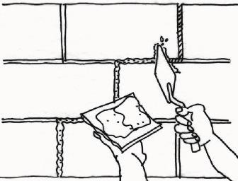
15 2. BUILDING A BLOCK WALL Constructing the walls uniformly over the plinth using a blocklayer s trowel. Set the block over the mix and verify that their edges touch the strings that connect the guide blocks. To set successive layers, alternate blocks so the ends Level Jointer Plumb-bob Trowel Laying the blocks Horizontal and vertical joints Do not make joints more than 1.5 cm thick. Joints that are too thick will weaken the wall. Level Control the plumb-bob on every course to make sure the wall is vertical. 1 to 1.5 cm 13
16 3. Creating the Columns Maximum distance between columns: 4.5 m Dimensions Collar Beam Maximum free height: 3 m Column-Wall Connection Column Leave toothed edges at the sides of the wall next to every column to provide Wall Level of slab on grade Footing 5 cm 2.5 cm Detail of the toothed wall edge 25 cm The minimum cross section of concrete columns has to be 25 cm x the wall width. 25 cm 25 cm In the foundation and the plinth, do not place big stones near columns. 15 cm 25 cm 14


17 3. CREATING THE COLUMNS Examples of column and beam reinforcing 15


18 3. CREATING THE COLUMNS Electrical installation in the Walls Embed electrical conduit inside false columns that are formed between toothed walls without Never weaken the wall by breaking it to place electrical conduits or accessories. Pipe Electrical switch Outlet Drain and ventilation pipes Embed the drain and ventilation pipes inside false columns that are formed between the toothed walls. Place #8 wire every three layers and wrap the pipes with #16 wire. #8 wire Fill the false columns with 1:6 fluid concrete. #16 wire 16

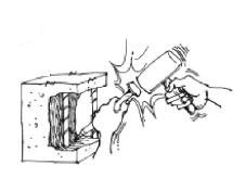
19 3. CREATING THE COLUMNS Pouring Concrete in Confining Columns Formwork and pouring After the walls are built, attach formwork to the walls for the concrete mix from the mixer to the upper part of the formwork. To prevent air pockets in columns, use concrete mix with less batches. Vibrate the concrete with a long rod to prevent air pockets. Concrete for columns 1 bucket of cement 2 buckets of coarse sand Lightly hit the form externally with a rubber hammer. 4 buckets of crushed stone 1 bucket of water to verify that the formwork is vertical. the forms. 17

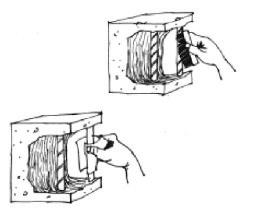
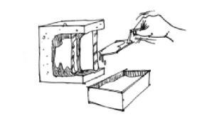
20 3. CREATING THE COLUMNS Formwork removal After pouring concrete into the columns, leave the forms up for 24 hours. Then carefully remove the forms and use them again for other columns. Curing Cure concrete after removal of the forms from the columns. Curing consists of watering the concrete elements at least 3 times a day to improve the hardening of the cement. Cure every concrete element for at least 7 days. Recommendation If a column has a large number of voids, immediately break and remove the concrete. Carefully clean the steel bars. Replace the formwork and pour the concrete again. 18

21 4. Attaching the Second Floor & Roof Confining Beams: Collar Beams: are important because they help Collar beams are the beams on top of the walls. Steel reinforcing for the collar beam Minimum Reinforcement Minimum reinforcement of all beams is: 4 steel bars Ø 3/8 in. with Ø 1/2 in. stirrups spaced 5 cm, 10 cm and the 25 cm from each end. wall width Roof Thickness has been poured 19


22 4. ATTACHING THE SECOND FLOOR & ROOF Beam-Column Connections Carefully place reinforcement bars at beam-column intersections. When you pour concrete in these areas, vibrate the concrete extensively with a rod so that no air pockets form. Tie steel bars with #16 wire at beam-column intersections. Detail of plan view In case the beam is not continuous, bend the steel bar horizontally. 15 cm Rebar bending length in beams has to be 15 cm. 15 cm Mortar Cube Spacers for beams Distance between mortar cubes: Approx. 1.5 m To keep beam reinforcing bars in a horizontal position, place 3 x 3 cm mortar cubes under them. #16 wire to attach rebar Longitudinal rebar 3 cm 3 cm 3 cm for the mortar and beams (proportion 1:4) 20


23 4. ATTACHING THE SECOND FLOOR & ROOF Beam Rebar Assembly After removing the formwork from the columns, place the steel reinforcement bars of the collar beams on top of the walls. Pouring of Beams All beams (collar, deep and flat) and lintels are poured simultaneously with the slabs. Concrete for beams & slabs 1 bucket of cement 2 buckets of coarse sand 4 buckets of crushed stone (maximum size 3/4 inch) 1 bucket of water 10 cm Steel reinforcement bars in joists Connection between confining beam and joist rebar Tie joist upper reinforcement bar to with #16 wire. No Pipes/Plumbing in beams Never bend beam rebars to pass drainage pipes. No Yes! 21
24 5. Calculating the Walls needed for an Earthquake-resistant House Your house has to have an adequate directions in order to resist an earthquake. How do I calculate have in either direction? The required number of walls depends on the type of soil where you build your house. Vulnerable House parallel to the street. Earthquake Earthquake Earthquake Earthquake Resistant House in both directions 22

25 5. CALCULATING THE WALLS NEEDED FOR AN EARTHQUAKE-RESISTANT HOUSE Wall Calculations To calculate the number of walls needed for a house with a maximum of two stories, follow these steps: Classify the soil of the place where you will build your house. Determine minimum wall density needed in each direc- Type of Soil Description Minimum Wall Density Required (%) Hard Rock Gravel 3 % Intermediate Soft or Loose Hard Clayish Sand Loose Sand Soft Clay 4 % 5 % 3. Calculate the roof area covering each floor in square meters. 4. Calculate the required horizontal area of REQUIRED HORIZONTAL AREA OF CONFINED WALLS IN FIRST FLOOR ROOF COVERED AREA OF FIRST FLOOR MINIMUM WALL DENSITY = X ROOF COVERED AREA OF SECOND FLOOR REQUIRED HORIZONTAL AREA OF CONFINED WALLS IN SECOND FLOOR = MINIMUM WALL DENSITY X 100 ROOF COVERED AREA OF SECOND FLOOR 23
26 5. CALCULATING THE WALLS NEEDED FOR AN EARTHQUAKE-RESISTANT HOUSE Example Suppose that your house will be constructed over a compact gravel-coarse and 50 m2 in the second floor. Wall density required for hard soil is 3%. To calculate the horizontal wall area needed in the To calculate the horizontal wall area necessary in the second floor, you only have to consider the roof area covering the second floor. That is, the wall area required for the rest of the second floor will be: Required Horizontal Area for Floor One (3/100) x (70+50m 2 ) = (3/100) x 120m 2 = 3,60m 2 Required Horizontal Area for Floor Two (3/100) x (50 m 2 ) = 1,5 m 2 5. walls in your house in each direction is greater than the required area. In the elevation only include walls made of structural block whose length is greater than 1 meter and columns. Do not include walls less than 1 meter in tion walls because these elements are not capable of resisting earthquakes. For each direction of your house up the areas of all the walls. To calculate the horizontal area of each wall in m2 multiply its length in meters by its thickness in meters. Length = 3 m Example Horizontal wall area 3 m x 0.15 m = 0.45 m 2 Thickness 15 cm = 0.15 m walls in every floor of your house and for each direction is greater than the required area that you calculated in the previous step. Total horizontal wall area (m2) > required horizontal area (m2) 24
27

28

29
The Construction and Maintenance of Masonry Buildings in Haiti
 Confined Masonry Workshop HANDBOOK The Construction and Maintenance of Masonry Buildings in Haiti MASONRI CHENE MANYEL POU TRAVAY Konstriksyon ak Reparasyon kay an Masonri an Ayiti 3rd Edition October
Confined masonry. An illustrated guide for masons. This manual explains this technique. Confined masonry. RC frames. Columns first, walls after
 S D C Confined masonry An illustrated guide for masons This manual explains this technique RC frames Columns first, walls after Confined masonry Walls first, columns after 1. Site selection and form of
Confined masonry. Definition
 Lesson prepared by the Swiss Agency for Development and Cooperation for the trainings at the Housing Reconstruction Centres Ballakot and Battagram 13 August 2006 1 Definition Confined Masonry is a construction
CONSTRUCTION AND MAINTENANCE OF MASONRY HOUSES
 NATURAL HAZARDS CONSTRUCTION AND MAINTENANCE OF MASONRY HOUSES NATURAL HAZARDS CONSTRUCTION AND MAINTENANCE OF MASONRY HOUSES For masons and craftsmen MARCIAL BLONDET Editor AUTHORS PUCP Director: Dr.
CONFINED MASONRY CONSTRUCTION
 CONFINED MASONRY CONSTRUCTION Mario Rodriguez, Universidad Nacional Autonoma de Mexico, Mexico BACKGROUND Confined masonry construction consists of unreinforced masonry walls confined with reinforced concrete
DESIGN AND MASONRY BASIC DESIGN GUIDELINES FOR CSEB. General principles for a good design
 DESIGN AND MASONRY BASIC DESIGN GUIDELINES FOR CSEB Good boots and a good hat. General principles for a good design That means built a good basement: (Minimum 25-cm high) And good overhangs: (Minimum 25
Guide book for building earthquake-resistant houses in confined masonry
 Guide book for building earthquake-resistant houses in confined masonry Guide book for building earthquake-resistant houses in confined masonry Guide book for technical training for earthquake-resistant
KEEP YOUR FAMILY SAFER FROM EARTHQUAKES AND TYPHOONS BY MAKING SURE YOUR HOUSE FOLLOWS THESE 6 BASIC PRINCIPLES
 KEEP YOUR FAMILY SAFER FROM EARTHQUAKES AND TYPHOONS BY MAKING SURE YOUR HOUSE FOLLOWS THESE 6 BASIC PRINCIPLES 5. WELL BRACED WALLS FIRMLY CONNECTED TO THE FOUNDATION 6. STURDY ROOF FIRMLY CONNECTED TO
APPENDIX 5: CONSTRUCTION CHECKLISTS
 APPENDIX 5: CONSTRUCTION CHECKLISTS This appendix presents the construction checklists for the various retaining wall mitigation strategies: 10.1 Void Fill 10.2 Surface Bond Overlay 10.3 Reinforced Overlay
SENTINEL BARRIER - GENERAL INSTALLATION GUIDELINES
 SENTINEL BARRIER - GENERAL INSTALLATION GUIDELINES Safety Precautions in the Excavation of a Sentinel Wedge take all necessary steps to make sure the pit is secured. Follow all OSHA requirements for digging
Public Disclosure Authorized. Public Disclosure Authorized. Public Disclosure Authorized. Public Disclosure Authorized
 Public Disclosure Authorized Public Disclosure Authorized Public Disclosure Authorized Public Disclosure Authorized I N F R A S T R U C T U R E SETTING OUT - FOUNDATION - CONCRETE WORKS - WALLS - ROOF
PHASE 1 Foundation & Drainage New Construction Phased Inspection Report John & Mary Doe 5237 Clinton Street, Denver, CO 80238
 PHASE 1 Foundation & Drainage New Construction Phased Inspection Report John & Mary Doe 5237 Clinton Street, Denver, CO 80238 PHASE 1 Foundation & Drainage New Construction Phased Inspection Report Buyers
Guide book for building earthquake-resistant houses in confined masonry
 Guide book for building earthquake-resistant houses in confined masonry NON-COUNTRY SPECIFIC VERSION Guide book for building earthquake-resistant houses in confined masonry Guide book for technical training
Building Construction
 Building Construction Shallow Foundations Module-III Introduction The foundation can be classified broadly into two types: Shallow foundations Deep foundations Shallow foundations Shallow Foundations When
ARCHITECTURAL DRAWINGS
 PROJECT DETAILS Implementation Partner: Project title: Grant No.: KIS062 Content : ARCHITECTURAL DRAWINGS SHEET NO. REHABILITATION OF GRANT NO.: - KIS062 COVER SHEET INDEX SHEET CONTENTS 01 02 03 04 05
A-ONE Insulated Forms Installation Manual
 A-ONE Insulated Forms Installation Manual Rockford, MN www.aoneform.com www.diversifoam.com info@diversifoam.com A-ONE Manual 180426.docx Disclaimer Notice The information in the A-ONE Insulated Forms
CONCRETE BLOCK MASONRY
 CONCRETE BLOCK MASONRY CONTENT Introduction Types Manufacturing process Properties Advantages Introduction These are the concrete blocks either hollow or solid. A hollow unit is that unit which has core
Nortrax Section David Manchester Road, Ottawa NON-STRUCTURAL METAL FRAMING 16 May 2014 Page 1
 16 May 2014 Page 1 PART 1 GENERAL 1.1 DESCRIPTION This section specifies steel studs wall systems, shaft wall systems, ceiling or soffit suspended or furred framing, wall furring, fasteners, and accessories
SECTION UNIT MASONRY
 SECTION 04200 UNIT MASONRY PART 1 GENERAL 1.01 SUMMARY A. Furnish labor, materials, and equipment and perform functions required in the installation and maintenance of the work covered by this Section.
Gravity Wall. A force to be reckoned with... Gravity (SRW) segmental retaining wall systems are structures
 segmental retaining wall systems are structures") A force to be reckoned with... Gravity (SRW) segmental retaining wall systems are structures lower in height that use the FrogStone unit weight combined with gravel core infill to resist earth pressures
A force to be reckoned with... Gravity (SRW) segmental retaining wall systems are structures lower in height that use the FrogStone unit weight combined with gravel core infill to resist earth pressures
Drainage, Road Drainage and Collection Pit A - EXCAVATION:
 57 Drainage, Road Drainage and Collection Pit SCHEDULE OF QUANTITY Sl.N o. 1 Particulars Qty Unit Rate Amount A - EXCAVATION: Earth work in EXCAVATION IN FOUNDATION TRENCHES IN ALL KIND OF SOIL including
Content Domain. NCCER Progress Blvd. Alachua, FL
 National Craft Assessment and Certification Program S P E C I F I C A T I O N S Masonry V1 June 2016 Focus Statement A journey level mason must be able to build, maintain and repair block and brick edifices,
Water for the World. 7 y
 Water for the World For effective water storage and water system operation, ground level storage tanks should be built for sufficient, and even excess, capacity and must be watertight to prevent leakage.
Concrete. Copyright: Quasar Management Services Pty Ltd
 Concrete This training package provides information on basic concrete, including materials, reinforcement, formwork, concrete mix, placement and curing for village infrastructure and houses common in South-
Fence Stone. Self locating Wall System
 Fence Stone Self locating Wall System Between wall panels End of walls at gate openings etc Internal & external right angles Do it yourself No bricklaying skills required Attractive & efficient For fences
1.02 STANDARD REFERENCES: The following standard specifications shall apply to the Work of this Section as indicated:
 SECTION 04220 CONCRETE UNIT MASONRY PART 1 - GENERAL 1.01 SCOPE: A. The CONTRACTOR shall furnish all labor, materials and equipment necessary for the masonry construction as shown on the drawings or as
Unit 4 Brick Masonry. Part Ⅰ Illustrated Words and Concepts. Figure 4-1 Basic Vocabulary of Bricklaying
 Part ⅠIllustrated Words and Concepts Figure 4-1 Basic Vocabulary of Bricklaying Figure 4-2 The Procedure for Building Brick Walls Figure 4-3 A Reinforced Brick Load bearing Wall Part ⅡPassages Passage
CHECKING MANUAL FOR THE EXAMINATION OF RESIDENTIAL PLANS AND INSPECTION OF RESIDENTIAL CONSTRUCTION IN GRENADA
 Grenada Hurricane Resilient Home Reconstruction Program: G-(HR) 2 Construction Quality Assurance Project (CQA) CHECKING MANUAL FOR THE EXAMINATION OF RESIDENTIAL PLANS AND INSPECTION OF RESIDENTIAL CONSTRUCTION
Pulaski County, Virginia
 Pulaski County, Virginia Typical Retaining Wall Details Based on the 2009 International Residential Code CONTENTS Timber Retaining Wall... 2 General Requirements... 2 Wall Construction... 2 Deadmen...
SECTION NON-STRUCTURAL METAL FRAMING
 SECTION 09 22 16 PART 1 - GENERAL 1.1 DESCRIPTION A. This section specifies steel studs wall systems, shaft wall systems, ceiling or soffit suspended or furred framing, wall furring, fasteners, and accessories
Note on the assessment:
 EXCERPTS Note on the assessment: The following is an excerpt from the book Post-disaster shelter: 10 Designs, IFRC, 2013. Inclusion of this design is for information purposes and does not necessarily imply
Self Locating Wall System
 From... Self Locating Wall System For fences from low gardens to 2.2 metres high The revolutionary new DIY fence system incorporating purpose made pier blocks for: v Between wall panels v End of walls
Concrete Framing Systems - Walls and Columns
 Concrete Framing Systems - Walls and Columns Casting a Concrete Wall Wall Footing Reinforcing Wall Forms Pouring Concrete Finishing the Concrete Controlling Cracking Insulating Concrete Forms (ICF) Tilt-Up
Anchor bolts ASTM F1554, Gr. 36 Wide flange beams ASTM A992, Fy = 50 ksi Misc. structural steel ASTM A36, Fy = 36 ksi
 STRUCTURAL NOTES MATERIAL STRENGTHS Structural Steel Reinforcing Steel Concrete Masonry Structural Lumber Anchor bolts ASTM F1554, Gr. 36 Wide flange beams ASTM A992, Fy = 50 ksi Misc. structural steel
INSPECTION REQUIREMENTS: FOUNDATIONS
 Foundations Page 1 of 9 Revision Date: 1/2/2018 DEVELOPMENT SERVICES BUILDING INSPECTION INSPECTION REQUIREMENTS: FOUNDATIONS INSPECTION CODE: 204 SCOPE: RESIDENTIAL APPLICABLE CODES: 2016 CBC, CRC, CPC,
Installation Manual. Foundations. Version 2
 Installation Manual Foundations Version 2 Contents Overview...1 Planning the Job... 2 Introducing DMX FlexSheet...2 Supplies Required...3 Tools Required...4 Preparing the Site...4 Where to Start?...5 Installing
design+phasing proposal May 24, 2010 Portland, Oregon Dear Reviewer,
 May 24, 2010 Portland, Oregon Dear Reviewer, The attached drawings have been prepared by volunteers with Architects Without Borders Oregon, with input from structural engineers from KPFF. Our intent is
Concrete Slab-on-Ground
 Concrete Slab-on-Ground This training package provides information on concrete slab-on-ground construction, including reinforcement, formwork, mix, placement and curing, for village infrastructure and
Interiors Sources Decor LLC. Method Statement BLOCK WORK. Civil Works 6/26/2016
 Method Statement BLOCK WORK Civil Works 6/26/2016 The purpose of this Work Method Statement for Block Works (Concrete Masonry Units) is to outline and describe in detail the procedure such as setting and
2002 Advanced Building Products, Inc., P.O. Box 98, Springvale, Maine TEL: ; FAX: ; WEBSITE:
 SECTION 07651 FLEXIBLE COPPER SHEET FLASHINGS Advanced Building Products, Inc. manufacturer many types of flexible copper sheet flashings. Due to their ductility, high tensile strength, and resistance
TECHNICAL EVALUATION REPORT No. 27/2008/2060
 TECHNICAL EVALUATION REPORT No. 27/2008/2060 Sheet 1 of 16 Sheets This report is a correct record of the measurements and observations made. The report is intended for the private information of those
Polycrete FLEX 850 Installation Manual. Version: 1.0 Revision: 1.3 Date:
 Polycrete FLEX 850 Installation Manual Version: 1.0 Revision: 1.3 Date: 2010-04-28 Polycrete is a registered trademark. Polycrete Flex 850 About this manual This manual is intended to assist the contractor,
ACCESSORY STRUCTURE Building permit information For 1 & 2-family dwellings
 ACCESSORY STRUCTURE Building permit information For 1 & 2-family dwellings Building Safety Department 400-2 nd Street South St. Cloud, MN 56301 (320) 255-7239 A building permit is required for any accessory
Supplemental Plan Correction Sheet for LA Residential Code Prescriptive Design (2014 LARC)
") Supplemental Plan Correction Sheet for LA Residential Code Prescriptive Design (2014 LARC) Plan Check Submittal Date: Plan Check #: Permit App.# Job Address: Applicant: Phone: ( ) Plan Check Engineer:
Supplemental Plan Correction Sheet for LA Residential Code Prescriptive Design (2014 LARC) Plan Check Submittal Date: Plan Check #: Permit App.# Job Address: Applicant: Phone: ( ) Plan Check Engineer:
1 Exam Prep Concrete Masonry Handbook Questions and Answers
 1 Exam Prep Concrete Masonry Handbook Questions and Answers 1. According to Concrete Masonry Handbook, a masonry unit is considered as normal weight if it has a density or unit weight of more than pounds
PS 3000 Installation Manual Step-By-Step Procedures C.9. DOOR AND WINDOW OPENINGS C.9.1 PREPARE IN ADVANCE. C.9.2 VBUCK CONSTRUCTION.
 C.9. DOOR AND WINDOW OPENINGS Openings for doors and windows are formed with bucks, or frames, which are constructed to the rough opening dimensions required for the doors and windows to be installed.
DESIGN OF PREFAB RC BUILDING USING EPS FOR DISASTER RESISTANCE
 DESIGN OF PREFAB RC BUILDING USING EPS FOR DISASTER RESISTANCE S. Selvi Rajan CSIR-Structural Engineering Research Centre Chennai, India 11 March 2016 CSIR-CBRI Roorkee Engineering of prefab structures
The Art of Construction and The Design. Direct, rebar chair.
 The Art of Construction and The Design Direct, rebar chair. Prefabricated element, made out of a thin steel rebar with plastic tipped legs in order to prevent corrosion of the support area between the
KORA_Req._for_Eng._Studies_on_Stouffer_Apts. KU Reference No
 000130 1 PURPOSE: Professional Engineering Consultants, P.A. (PEC) was engaged by University of Kansas Design & Construction Management to perform an assessment of Stouffer Place Apartment Building 20
REINFORCED CONCRETE MASONRY SECTION
 SECTION 04 22 02 - REINFORCED CONCRETE MASONRY PART 1 - GENERAL 1.1 RELATED DOCUMENTS A. Drawings and general provisions of Contract, including General and Supplementary Conditions and Division 01 Specification
Structural Conditions Assessment of Current Lapeer District Schools Administration Building 250 Second Street, Lapeer, Michigan
 November 2, 2015 Melissa A. Malcolm Library Director Lapeer District Library 201 Village West Dr S Lapeer, MI 48446 RE: Structural Conditions Assessment of Current Lapeer District Schools Administration
Module number 3 provides an on-line, self-paced training seminar on chapter 4, foundations and chapter 5, floors from the residential code of ohio.
 Module number 3 provides an on-line, self-paced training seminar on chapter 4, foundations and chapter 5, floors from the residential code of ohio. 1 This chapter sets forth the prescriptive requirements
NON ENGINEERED REINFORCED CONCRETE BUILDINGSS
 Chapter 8 NON ENGINEERED REINFORCED CONCRETE BUILDINGS 8.1 INTRODUCTION With the spread of reinforced concrete construction to semi-urban and rural area in various countries, often buildings are constructed
Appendix 4. Bills of Quantities
 Appendix 4. Bills of Quantities 201 A4.1 Deep trench latrines Partitions of local materials 1m apart Timber foot rests and floor plates Lightweight timber frame Excavated soil (used for back-fill) Plastic
Uses. architectural works. 1) Building foundations, walls, piers, pillars, and. 2) Lintels, Beams, beams Arches, domes etc.,
 Building foundations, walls, piers, pillars, and. 2) Lintels, Beams, beams Arches, domes etc.,") STONE MASONRY etc. Stone Masonry The construction of stones bonded together with mortar is termed as stone masonry where the stones are available in a abundance in nature, on cutting and dressing to the
STONE MASONRY etc. Stone Masonry The construction of stones bonded together with mortar is termed as stone masonry where the stones are available in a abundance in nature, on cutting and dressing to the
Good Construction Practices Part I
 Good Construction Practices Part I This report is solely for the internal use. No part of it may be circulated, quoted, or reproduced for distribution outside the company organization without prior written
Supplemental Plan Correction Sheet for LA Residential Code Prescriptive Design (2011 LARC)
") Supplemental Plan Correction Sheet for LA Residential Code Prescriptive Design (2011 LARC) Plan Check Submittal Date: Plan Check #: Permit App.# Job Address: Applicant: Phone: ( ) P.C. Engineer: Phone:
Supplemental Plan Correction Sheet for LA Residential Code Prescriptive Design (2011 LARC) Plan Check Submittal Date: Plan Check #: Permit App.# Job Address: Applicant: Phone: ( ) P.C. Engineer: Phone:
Paragraph Description Page No General Materials Concrete Masonry Work Altitude Valve Vault Cover 25-4
 City of Columbia Engineering Regulations PART 25: SPECIFICATIONS FOR ALTITUDE VALVE VAULT Table of Contents Paragraph Description Page No. 25.1 General 25-1 25.2 Materials 25-1 25.3 Concrete Masonry Work
General Brick Installation Instructions
 Excellent Resource for Clay Paver Installation: http://www.bia.org/resources/clay-brick-pavers/clay-paver-informational- Resources These are general guidelines only. Check your paver manufacturer's recommendations
Zenon Panel Assembly Guideline - Page 1
 Zenon Panel Assembly Guideline www.zenonpanel.com - Page 1 This guide is the document that summarizes the key points to be considered in the assembly of Zenon Panel. It is very important to consider the
Building Division Informational Handout
 CITY OF SAN JOSÉ, CALIFORNIA Building Division Informational Handout Conventional Light Frame Construction Design Provisions 2007 CBC Handout No. 2-21 Published: 1/1/08 Page 1 of 3 This document summarizes
ICBO Evaluation Service, Inc Workman Mill Road, Whittier, California
 Reissued June 1, 2002 ICBO Evaluation Service, Inc. 5360 Workman Mill Road, Whittier, California 90601 www.icboes.org Filing Category: DESIGN Concrete DURISOL WALL FORMS FOR CONCRETE CONSTRUCTION DURISOL
LIQUID RUBBER INDUSTRIES ENGINEERING SPECIFICATIONS FOR ENGINEERS AND ARCHITECTS. Diagram 1: Standard Membrane Continuation 150 mm Overlap
 LIQUID RUBBER INDUSTRIES ENGINEERING SPECIFICATIONS FOR ENGINEERS AND ARCHITECTS Diagram 1: Standard Membrane Continuation 150 mm Overlap Ensure Membrane to Membrane Contact Diagram 2: Membrane Continuation
TRANSPORTATION AND OTHER DAMAGE
 TRANSPORTATION AND OTHER DAMAGE Effects of Wind Contact with an overpass Wind fallen tree damage Contact with a guard rail Contractor doing repairs for transit damage done by a transporter while shipping
Foundation/Site Work Code Requirements
 Q: What is a Foundation Only permit and why did I receive one when I filed for a full Building Permit? All Building Permits for new construction and additions are reviewed for zoning compliance. This review
GEOGRID CONNECTION DETAIL OLYMPIA RADIUS UNIT
 PLACE TWO STANDARD CONNECTORS IN EACH UNIT AS SHOWN (VERTICAL ORIENTATION) INSERT TWO CONNECTORS PER HORIZONTALLY ORIENTED BLOCK; INSERT ONE CONNECTOR PER VERTICALLY ORIENTED BLOCK SHIM BETWEEN BLOCK COURSES
FEMA P-593 STEP-BY STEP PRESCRIPTIVE RETROFIT FOR CRIPPLE WALL BRACING & ANCHORAGE TO FOUNDATION
 INTRODUCTION Objective of provisions: The provisions of IEBC Appendix Chapter A3 are intended to reduce hazard of earthquake-induced damage (IEBC A301.1). These provisions are not intended to eliminate
mortarless masonry Design Manual Part 1 (IS 456:2000) Section 1 Page 1 IS 456:2000 PLAIN AND REINFORCED CONCRETE - CODE OF PRACTICE
 Section 1 Page 1 IS 456:2000 PLAIN AND REINFORCED CONCRETE - CODE OF PRACTICE") SECTION 1. mortarless masonry Design Manual Part 1 (IS 456:2000) Section 1 Page 1 1.1 Overview of IS 456:2000 IS 456:2000 PLAIN AND REINFORCED CONCRETE - CODE OF PRACTICE IS 456:2000 is the current Indian
SECTION 1. mortarless masonry Design Manual Part 1 (IS 456:2000) Section 1 Page 1 1.1 Overview of IS 456:2000 IS 456:2000 PLAIN AND REINFORCED CONCRETE - CODE OF PRACTICE IS 456:2000 is the current Indian
Installing DELTABEAM. Installation of DELTABEAM. Deliveries. Storage on-site
 Installing DELTABEAM Installation of DELTABEAM These DELTABEAM installation instructions are intended to complement the project s erection plan. Peikko s technical support can help with the erection plan
SITE VISIT REPORT DATE: JOB: NO. OF VISIT: PAGE OF : PURPOSE OF VISIT: CONTRACTOR: Items to be checked Observations Actions SETTING OUT
 SETTING OUT Correct to boundaries Correct to building lines? Diagonals accurate? Levels correct? EXCAVATIONS Adjoining structures OK? Centres of foundations line with walls? Bottoms of trenches uniform,
VARIOUS TYPES OF SLABS
 VARIOUS TYPES OF SLABS 1 CHOICE OF TYPE OF SLAB FLOOR The choice of type of slab for a particular floor depends on many factors. Economy of construction is obviously an important consideration, but this
Foundation or Footing Design: Part 1
 Foundation or Footing Design: Part 1 Foundation or Footing Footings are structural elements that transmit column or wall loads to the underlying soil below the structure. Footings are designed to transmit
PLEASE READ ENTIRE INSTRUCTION MANUAL BEFORE PROCEEDING!
 INSTALLATION GUIDE This guide is intended to aide in the installation of Dura-Trench systems. There are many different applications and situations for the use of this product and the installation procedures
Technical Notes 11B - Guide Specifications for Brick Masonry, Part 3 Rev [Feb. 1972] (Reissued Sept. 1988) INTRODUCTION
![Technical Notes 11B - Guide Specifications for Brick Masonry, Part 3 Rev [Feb. 1972] (Reissued Sept. 1988) INTRODUCTION](/thumbs/78/77915427.jpg "Technical Notes 11B - Guide Specifications for Brick Masonry, Part 3 Rev [Feb. 1972] (Reissued Sept. 1988) INTRODUCTION") Technical Notes 11B - Guide Specifications for Brick Masonry, Part 3 Rev [Feb. 1972] (Reissued Sept. 1988) INTRODUCTION This Technical Notes contains the guide specifications in CSI format for Part III
Technical Notes 11B - Guide Specifications for Brick Masonry, Part 3 Rev [Feb. 1972] (Reissued Sept. 1988) INTRODUCTION This Technical Notes contains the guide specifications in CSI format for Part III
BEHAVIOR OF NON-ENGINEERED HOUSES DURING PISCO EARTHQUAKE 15/8/2007
 BEHAVIOR OF NON-ENGINEERED HOUSES DURING PISCO EARTHQUAKE 15/8/2007 C. Zavala 1, M. Estrada 1, L. Chang 2,L. Cardenas 2, J. Tayra 2,L. Conislla 2 and G. Guibovich 2 1 Professor, CISMID, Faculty of Civil
CONCRETE WORK CONCRETE WORK. Underground Electric Distribution Standards I. SCOPE APPLICABLE STANDARDS
 Underground Electric Distribution Standards I. SCOPE This section includes the standards for concrete, reinforcing steel, formwork, concrete placement, curing, and construction joints. Concrete work for
Structural Tests and Special Inspections Form. Inspection of Fabricators (1704.2)
") Inspection of Fabricators (1704.2) Furnish inspection reports (1704.2.1) - Fabricators that have not been approved Provide a Certificate of Compliance (1704.2.2) - Approved Fabricators Steel Construction
Inspection of Fabricators (1704.2) Furnish inspection reports (1704.2.1) - Fabricators that have not been approved Provide a Certificate of Compliance (1704.2.2) - Approved Fabricators Steel Construction
Note on the assessment:
 EXCERPTS Note on the assessment: The following is an excerpt from the book Post-disaster shelter: 10 Designs, IFRC, 2013. Inclusion of this design is for information purposes and does not necessarily imply
VOLUNTARY - EARTHQUAKE HAZARD REDUCTION IN EXISTING HILLSIDE BUILDINGS (Division 94 Added by Ord. No. 171,258, Eff. 8/30/96.)
") DIVISION 94 VOLUNTARY - EARTHQUAKE HAZARD REDUCTION IN EXISTING HILLSIDE BUILDINGS (Division 94 Added by Ord. No. 171,258, Eff. 8/30/96.) SEC. 91.9401. PURPOSE. (Amended by Ord. No. 172,592, Eff. 6/28/99,
DIVISION 94 VOLUNTARY - EARTHQUAKE HAZARD REDUCTION IN EXISTING HILLSIDE BUILDINGS (Division 94 Added by Ord. No. 171,258, Eff. 8/30/96.) SEC. 91.9401. PURPOSE. (Amended by Ord. No. 172,592, Eff. 6/28/99,
SECTION UNIT MASONRY ASSEMBLIES
 PART 1 - GENERAL 1.1 SUMMARY A. Section Includes: 1. Concrete masonry units. 2. Decorative masonry units. 3. Mortar and grout. 4. Steel reinforcing bars. 5. Masonry joint reinforcement. 6. Ties and anchors.
CHAPTER 10: GENERAL STRUCTURAL DETAILS
 CHAPTER 10: GENERAL STRUCTURAL DETAILS 10.1 GENERAL It shall be in accordance with JSCE Standard Specification (Design), 9.1, "steel" shall be taken to signify "steel or CFRM". 10.2 CONCRETE COVER (1)
Confined Masonry Buildings as Low- Cost Engineered Housing System
 Workshop on Performance Evaluation of Housing Units Confined Masonry Buildings as Low- Cost Engineered Housing System Dr. Vaibhav Singhal Department of Civil and Environmental Engineering Indian Institute
Note on the assessment:
 Excerpt from: Transitional shelter: 8 designs, IFRC, 2012 Note on the assessment: The following is an excerpt from the Book Transitional Shelters: 8 Designs, IFRC, 2012, available from www.sheltercasestudies.org.
BRICKWORK 3.5 BRICKWORK 1 GENERAL
 BRICKWORK 1 GENERAL 1.1 INSPECTION Notice Give sufficient notice so that inspection may be made of the following: - Set out of brickwork to lintels, arches and other architectural features. - Damp-proof
Schöck Isokorb Type CM
 Schöck Isokorb Type Schöck Isokorb Type The Schöck Isokorb Type is suitable for cantilevered reinforced concrete slabs. (C for concrete slab) It transmits negative moment (M) and positive shear force.
Mix and lay concrete tutor notes
 Mix & lay concrete Tutor Tutor Mix and lay concrete tutor notes What students will learn When they have fi nished this module, students should be able to: Prepare the ground for a concrete slab Build formwork
INSTALLATION GUIDE PLEASE READ ENTIRE INSTRUCTION MANUAL BEFORE PROCEEDING!
 DURA - TRENCH INSTALLATION GUIDE This guide is intended to aide in the installation of Dura-Trench systems. There are many different applications and situations for the use of this product and the installation
CHAPTER 2 SPECIMEN DETAILS, TEST SETUP AND TESTING PROCEDURE
 38 CHAPTER 2 SPECIMEN DETAILS, TEST SETUP AND TESTING PROCEDURE 2.1 GENERAL In the conducted experimental study, three two-dimensional partially infilled RC frames were cast and tested under quasi-static
twenty two concrete construction: flat spanning systems, columns & frames ARCHITECTURAL STRUCTURES: FORM, BEHAVIOR, AND DESIGN
 ARCHITECTURAL STRUCTURES: FORM, BEHAVIOR, AND DESIGN DR. ANNE NICHOLS SUMMER 2014 lecture twenty two concrete construction: http:// nisee.berkeley.edu/godden flat spanning systems, columns & frames Concrete
CONCRETE FORMWORK CHECKLIST AT SITE
 CONCRETE FORMWORK CHECKLIST AT SITE Concrete formwork is a temporary supporting structure for concrete when it is placed at the construction site to keep the concrete in position and shape till it gets
Combined footings A mat or raft or floating foundation Pile caps
 Foundation or Footing Design: Part 1 Courtesy of Dr. Latifee s IMI research group, Text books (Design of concrete structures by McCormac etc.) and others Foundation or Footing Footings are structural elements
CONSTRUCTION OF ELEVATED WATER TANK & WATER WELL VAULT INTERNATIONAL CAMPUS AUGUST 2018
 CONSTRUCTION OF ELEVATED WATER TANK & WATER WELL VAULT INTERNATIONAL CAMPUS AUGUST 2018 E S SEPTIC TANK N W BASKETBALL COURT ELEVATED WATER TANK MAN HOLE WATER WELL VAULT 1 0 SITE PLAN OF NO NAME INITL
1. Remove worn-out old plaster (or any other finishing).
.") Annexure A SCOPE OF WORK The work should be implemented by contractor under the supervision of Norwegian Refugee Co BoQ s and below instructions. NRC reserves the right to provide further clarifications/drawings
Annexure A SCOPE OF WORK The work should be implemented by contractor under the supervision of Norwegian Refugee Co BoQ s and below instructions. NRC reserves the right to provide further clarifications/drawings
SLAB ON GRADE Insul-Joint or Expansion Joint Material as Required by A/E Specifications AquaCheck Liquid Coating 400 (Waterproofing Membrane) with Aqu
 with Aqu") INSTALLATION INSTRUCTIONS Note: The following installation instructions are based off of ASTM E 1643 (Standard Practice for Installation of Water Vapor Retarders Used in Contact with Earth or Granular
INSTALLATION INSTRUCTIONS Note: The following installation instructions are based off of ASTM E 1643 (Standard Practice for Installation of Water Vapor Retarders Used in Contact with Earth or Granular
GOOD CONSTRUCTION PRACTICES IN BUILDINGS
 CSIR- CBRI TIPS FOR GOOD CONSTRUCTION PRACTICES IN BUILDINGS स.एस.आई.आर.- क द र य भवन अन स ध न स स थ न र ड़क - 247667, भ रत CSIR- Central Building Research Institute Roorkee - 247667, India CONSTRUCTION
1 Exam Prep Placing Reinforcing Bars Tabs and Highlights
 1 Exam Prep Placing Reinforcing Bars Tabs and s These 1 Exam Prep Tabs are based on the CRSI Placing Reinforcing Bars Recommended Practices, 9 th Edition. Each 1 Exam Prep tabs sheet has five rows of tabs.
Conditions of the Contract and Division 1 General Requirements are a part of this section.
 NOTES TO SPECIFIER General notes about the specifications and the reasons for them are listed here in general statements. Use this as a guide when choosing the correct selection of statements that apply
SECTION CONCRETE CURBS, GUTTERS AND SIDEWALKS. A. Formwork complete with shoring, bracing and anchorage.
 SECTION 02528 CONCRETE CURBS, GUTTERS AND SIDEWALKS PART 1 GENERAL 1.01 WORK INCLUDED A. Formwork complete with shoring, bracing and anchorage. B. Concrete reinforcement complete with required supports,
Structural Technical Report I October 5, 2006 Structural Concepts / Structural Existing Conditions Report
 1 THE ODYSSEY ARLINGTON, VA Aaron Snyder Structural Option Advisor: M. Kevin Parfitt, PE Structural Technical Report I October 5, 2006 Structural Concepts / Structural Existing Conditions Report Executive
CRD-C Standard Test Method for Comparing Concretes on the Basis of the Bond Developed with Reinforced Steel
 Standard Test Method for Comparing Concretes on the Basis of the Bond Developed with Reinforced Steel 1. Scope 1.1 This test method covers comparison of concretes on the basis of the bond developed with