GEOTECHNICAL INVESTIGATION For PROPOSED OUTDOOR THEATER 495 Upper Park Road APN Santa Cruz, California
|
|
|
- Cameron James
- 6 years ago
- Views:
Transcription
1 GEOTECHNICAL INVESTIGATION For PROPOSED OUTDOOR THEATER 495 Upper Park Road APN Santa Cruz, California Prepared For SANTA CRUZ SHAKESPEAR Santa Cruz, California Prepared By DEES & ASSOCIATES, INC. Geotechnical Engineers Project No. SCR-0962 DECEMBER 2015
2 December 7, 2015 Project No. SCR-0962 SANTA CRUZ SHAKESPEAR RICK WRIGHT 500 Chestnut Street Santa Cruz, California Subject: Reference: Geotechnical Investigation Proposed Outdoor Theater 495 Upper Park Road APN Santa Cruz, California Dear Mr. Wright: As requested, we have completed a Geotechnical Investigation for the new outdoor theater proposed at the referenced site. The purpose of our investigation was to evaluate the soil conditions in the vicinity of the proposed improvements and provide geotechnical recommendations for the proposed project. This report presents the results, conclusions and recommendations of our investigation. If you have any questions regarding this report, please call our office. Very truly yours, DEES & ASSOCIATES, INC. Rebecca L. (Dees) Boyd Geotechnical Engineer G.E Copies: 4 to Addressee 2
3 LETTER OF TRANSMITTAL TABLE OF CONTENTS GEOTECHNICAL INVESTIGATION 4 Introduction 4 Purpose and Scope 4 Project Location and Description 4 Field Investigation 5 Laboratory Testing 5 Subsurface Soil Conditions 5 Groundwater 6 Seismicity 6 Liquefaction 7 Landsliding 7 DISCUSSIONS AND CONCLUSIONS 8 Page No. RECOMMENDATIONS 9 General Site Grading 9 Utility Trenches 10 Retaining Wall Lateral Pressures 10 Conventional Spread Footing Foundations 11 Site Drainage 12 Plan Review, Construction Observation and Testing 12 LIMITATIONS AND UNIFORMITY OF CONDITIONS 13 APPENDIX A 14 Site Vicinity Map 15 Site Plan 16 Unified Soil Classification System 17 Test Boring Logs 18 3
4 GEOTECHNICAL INVESTIGATION Introduction This report presents the results of our Geotechnical Investigation for the new outdoor theater proposed at 495 Upper Park Road in Santa Cruz, California. Purpose and Scope The purpose of our investigation was to explore and evaluate surface and near surface soil conditions in the vicinity of the proposed theater and provide geotechnical recommendations for design and construction of the proposed improvements. The specific scope of our services was as follows: 1. Site reconnaissance and review of available data in our files regarding the site and region. 2. Exploration of subsurface conditions consisting of logging and sampling of four (4) exploratory borings. The soil samples obtained were sealed and returned to the laboratory for testing. 3. Laboratory testing of collected soil samples. 4. Engineering analysis and evaluation of the resulting field and laboratory test data. Based on our findings, we have developed geotechnical design criteria for general site grading, retaining walls, slabs-on-grade and general site drainage. 5. Preparation of this report presenting the results of our investigation. Project Location and Description The project site is located at 495 Upper Park Road in Santa Cruz, California; Figure 1, which is accessed within De Laveaga Park. The new theater will be located on gentle slopes along the east edge of a north-south trending ridgeline. Slope gradients are on the order of 5 to 10 percent where the improvements are planned. The slopes below the proposed building areas are steep and on the order of 40 to 60 percent. See Figure 2. The theater improvements will include a raised stage with a trap room below. Portions of the trap room will be excavated below grade and retaining walls will be used to retain the cuts. Amphitheater seating will be provided in front of the stage and will consist of benches with gravel walkways. Fill will be placed along the east edge of the ridge top to level out the seating area and a retaining wall will be used to retain the fill. We understand the walkways to the theater area will be gravel and will generally follow the existing contours. A level pad will be graded adjacent to the existing paved access driveway to accommodate temporary trailers. No other grading is proposed. Field Investigation 4
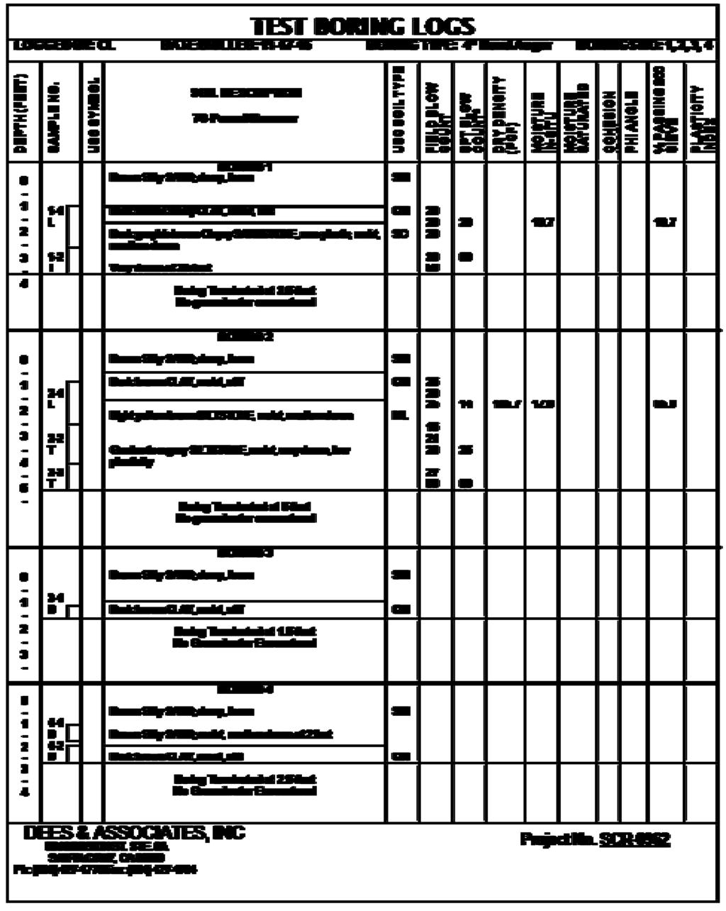
5 Subsurface conditions at the site were explored on November 17, 2015 with four (4) exploratory borings drilled with 4-inch diameter hand auger equipment. The approximate locations of the exploratory borings are indicated on Figure 2. Our test boring logs are included on Figure 4. The soils observed in the test borings were logged in the field and described in accordance with the Unified Soil Classification System (D2487 and D2488), Figures 3. The Test Boring Logs denote subsurface conditions at the locations and times observed, and they are not warranted that they are representative of subsurface conditions at other locations or times. Representative soil samples were obtained from the exploratory borings. These samples were recovered using the 3.0-inch O.D. Modified California Sampler (L), the Standard Terzaghi Sampler (T) and from grab samples from the auger cuttings. The penetration resistance blow counts for the (L) and (T) samples noted on the boring logs were obtained as the sampler was dynamically driven into the in situ soil. The process was performed by dropping a 70 -pound hammer a 30-inch free fall distance and driving the sampler up to 18 inches and recording the number of blows for each 6-inch penetration intervalthe blows recorded on the boring logs present the accumulated number of blows that were required to drive the last 12 inches. A standard hammer is 140 pounds so the blow counts were divided in half to account for the energy difference. The blow counts for the large samples indicated on the logs have been converted to equivalent standard penetration field test values. Laboratory Testing Moisture content and dry density tests were performed on representative soil samples to determine the consistency of the soil and the moisture variation throughout the explored soil profile. Grain size analysis was performed to aid in soil classification. The results of our field and laboratory testing appear on the "Log of Test Boring", opposite the sample tested. Subsurface Soil Conditions The County of Santa Cruz Geology map indicates the site is underlain by Terrace deposits, undifferentiated (Pleistocene) which are described as, Weakly consolidated to semi-consolidated heterogeneous deposits of moderately to poorly sorted silt, silty clay, sand, and gravel. The Terrace Deposits are underlain by the Purisima Formation (Pliocene and upper Miocene) which is described as, Very thick bedded yellowish-gray tuffaceous and diatomaceous siltstone containing thick inter-beds of bluish-gray, semifriable, fine-grained andesitic sandstone. Our borings encountered 1 to 2 feet of loose silty sand over a thin 6 to 8 inch thick clay layer over Purisima bedrock. The Purisima consists of inter-bedded sandstone and siltstone. Sandstone was encountered in Boring 1 and siltstone was encountered in Boring 2. Borings 3 and 4 were terminated in clay and did not penetrate the bedrock. 5
6 The bedrock is medium dense in the top 18 inches and very dense below the upper 18 inches. The soils beneath the site are classified as a Site Class C according to the 2013 CBC. Groundwater No groundwater was encountered in our borings. Groundwater levels denote groundwater conditions at the locations and times observed, and it is not warranted they are representative of groundwater conditions at other locations or times. Groundwater levels can vary due to seasonal variations and other factors not evident at the time of our investigation. Seismicity The following is a general discussion of seismicity in the project area. A detailed discussion of seismicity is beyond the scope of our services. The closest faults to the site are the San Andreas Fault, the Zayante-Vergeles Fault, the offshore San Gregorio Fault and the offshore Monterey Bay-Tularcitos Fault. The San Andreas Fault is the largest and most active of the faults in the site vicinity. However, each fault is considered capable of generating moderate to severe ground shaking. It is reasonable to assume that the proposed development will be subject to at least one moderate to severe earthquake from one of the faults during the next fifty years. San Andreas Fault Zone 8.9 miles to the northeast San Gregorio Fault Zone 11.6 miles to the southwest Zayante Fault Zone 6.0 miles to the northeast Monterey Bay- Tularcitos Fault Zone 8.7 miles to the southwest Structures designed according to the 2013 California Building Code may use the following parameters in their analysis. The following ground motion parameters may be used in seismic design and were determined using the USGS Seismic Design Map and ASCE Ss S1 SMs SM1 SDs SD g g g g g g PGAm Seismic Design Category (SDC) Occupancy Categories l and ll 0.5 g D Liquefaction 6
7 Liquefaction occurs when saturated fine grained sands, silts and sensitive clays are subject to shaking during an earthquake and the water pressure within the pores builds up leading to loss of strength. There is a very low potential for liquefaction to occur site due to the lack of a groundwater table and the density of the subsoils. Landsliding The project site is located on the edge of a ridge adjacent to steep slopes. The slopes are comprised of dense sandstone and siltstone bedrock with a thin soil cover. Sandstone was encountered about 1.5 to 3 feet below grade in our borings and sandstone exposures were observed on the slope about 3 feet below the top of the slope. There is a low potential for deep seated landslides to develop at the site. There is a moderate to high potential for shallow slump slides to occur within the soil overlying the bedrock. To protect the improvements from being undermined from soil slumping, we recommend that all foundations located within 15 feet of the edge of the slope be embedded into sandstone bedrock and have at least 8 feet of soil between the base of the footings and the adjacent slope face, measured horizontally. 7
8 DISCUSSIONS & CONCLUSIONS Based on the results of our investigation, the proposed outdoor theater is feasible from a geotechnical standpoint provided the recommendations presented in this report are incorporated into the design and construction of the proposed improvements. Primary geotechnical concerns for the project include embedding foundations into bedrock, setting foundations back from steep slopes, controlling drainage and designing structures to resist strong seismic shaking. Foundations should penetrate the loose surface soils and potentially expansive clay and be embedded at least 12 inches into weathered bedrock. The base of foundations should be setback at least 8 feet from the adjacent slope face. Surface runoff from improvements should be dispersed as much as possible. Concentrated runoff should be collected and dispersed on gentle slopes in a controlled manner. Concentrated runoff shall not be allowed to flow over steep slopes. If necessary, berms or lined swales should be used to prevent concentrated runoff from flowing over the top of slopes. The proposed improvements will most likely experience strong seismic shaking during the design lifetime. Structures should be designed utilizing current seismic design standards. 8
9 RECOMMENDATIONS The following recommendations should be used as guidelines for preparing project plans and specifications: General Site Grading 1. The geotechnical engineer should be notified at least four days prior to any grading or foundation excavating so the work in the field can be coordinated with the grading contractor and arrangements for testing and observation can be made. The recommendations of this report are based on the assumption that the geotechnical engineer will perform the required testing and observation during grading and construction. It is the owner's responsibility to make the necessary arrangements for these required services. 2. We understand grading will consist of 4 to 8 foot high excavations for the trap room below the stage, 4 to 6 feet of fill along the eastern edge of the amphitheater seating area and a 6 to 8 foot cut slope where the temporary trailers are proposed. 3. Areas to be graded should be cleared of obstructions, vegetation, and other unsuitable material. Voids created during site clearing should be backfilled with engineered fill. 4. Where fill is planned to raise grade, areas to receive engineered fill should be scarified and compacted to provide a firm base for fill placement. 5. Engineered fill should be placed in thin lifts not exceeding 8 inches in loose thickness; moisture conditioned to 1 to 2 percent over optimum moisture content and compacted to at least 90 percent relative compaction. 6. Temporary cut slopes may be inclined vertical for a height of 4 feet then inclined at a maximum 1:1 (h:v) for heights up to 15 feet. 7. Permanent cut and fill slopes should be inclined no steeper than 2:1 (horizontal to vertical). 8. Fill slopes that are not retained with a retaining wall and are over 3 feet in height should be keyed and benched at least 3 feet below grade. The key should be at least 6 feet wide for fills less than 5 feet high and 8 feet wide for fills more than 5 feet high. 9. A gravel backdrain will be required at the back of fill slopes where potential seepage zones exist. The location and depths of the subdrains should be determined by the soils engineer during construction. 9
10 10. The relationship between moisture content and dry unit weight shall be based on ASTM Test Designation D1557. The relative density and moisture content of the compacted soil shall be based on ASTM D The on-site soils with the exception of the 6 to 8 inch thick clay layer encountered in the top 3 feet are suitable for use as engineered fill. Imported soils used for engineered fill should be non-expansive (Plasticity Index less than 15), be free of organic material, and contain no rocks or clods greater than 6 inches in diameter, with no more than 15 percent larger than 4 inches. Soils with more than 3 percent organic matter by weight should be considered organic and not suitable as engineered fill. 12. Engineered fill should be observed and tested by our firm. In-place density tests should be performed as follows: one test for every 12 inches of material placed for fill slopes, in trenches or around structures; one test for every 1,000 square feet for relatively thin fill sections and one test whenever there is a definite suspicion of a change in the quality of moisture control or effectiveness in compaction. The actual testing schedule should be determined by a representative from our firm at the time of grading. 13. After the earthwork operations have been completed and the soil engineer has finished their observation of the work, no further earthwork operations shall be performed except with the approval of and under the observation of the soil engineer. Utility Trenches 14. Utility trenches placed parallel to structures or retaining walls should not extend within an imaginary 1:1 (horizontal to vertical) plane projected downward from the bottom edge of the adjacent footing. 15. Trenches may be backfilled with compacted engineered fill placed in accordance with the grading section of this report. The backfill material should not be jetted in place. Retaining Wall Lateral Pressures 16. Retaining walls should be designed to resist both lateral earth pressures and any additional surcharge loads. 17. Unrestrained retaining walls may be designed to resist an active lateral earth pressure of 45 pcf equivalent fluid weight for level backfills and 55 pcf equivalent fluid weight for backslopes inclined up to 3:1 (horizontal to vertical). 18. Restrained retaining walls may be designed to resist an at rest earth pressure of 65 pcf equivalent fluid weight for level backfills and 85 pcf equivalent fluid weight for backfills inclined up to 3:1 (horizontal to vertical). 10
11 19. Retaining walls over 6 feet high should include a seismic surcharge load of 14 pcf, EFW, in addition to the above lateral earth pressures. The resultant dynamic pressure should be applied at a point 0.6 H above the base of the wall. 20. The above lateral pressures assume the walls are fully drained to prevent hydrostatic pressure behind the walls. Drainage materials behind the wall should consist of either Class 1 or Class 2 permeable material (Caltrans Specification 68). Place filter fabric between Class 1 permeable material and backfill. No filter fabric is required with Class 2 permeable material. The drains should extend from the base of the walls to within 12 inches of the top of the backfill. A perforated pipe should be placed (holes down) about 2 inches above the bottom of the wall and be tied to a suitable drain outlet. Wall backdrains should be plugged at the surface with clayey material to prevent infiltration of surface runoff into the backdrains. Conventional Spread Footing Foundations 21. Conventional spread footings embedded into firm, native soil may be used to support the proposed retaining walls. 22. Footings should be embedded at least 12 inches into weathered bedrock and there should be at least 8 feet of soil between the base of the footing and the adjacent slope face. Weathered bedrock is located below the upper 18 to 24 inches of topsoil and clay. 23. Footings should be a minimum of 12 inches wide. 24. Footings located adjacent to other footings or utility trenches should have their bearing surfaces founded below an imaginary 1.5:1 plane projected upward from the bottom edge of the adjacent footings or utility trenches. 25. Foundations designed in accordance with the above may be designed for an allowable soil bearing pressure of 3,000 psf. The allowable bearing capacity may be increased by 1/3 for short term seismic and wind loads. 26. Total and differential settlements under the proposed light loads are anticipated to be less than 1/2 inch respectively. 27. Lateral load resistance for structures supported on footings may be developed in friction between the foundation bottom and the supporting subgrade. A friction coefficient of 0.35 is considered applicable. Where footings are poured neat against firm weathered bedrock, a passive lateral earth pressure of 350 pcf may be used. The top 6 inches of weathered bedrock and all portions of the footing with less than 8 feet of soil between the face of the footing and the adjacent slope face should be neglected in passive design. 11
12 28. Prior to placing concrete, foundation excavations should be observed by the soils engineer. Drainage 29. Surface drainage should include provisions for positive gradients so that surface runoff is not permitted to pond adjacent to foundations or other improvements. Where bare soil or pervious surfaces are located next to the stage foundation, the ground surface within 10 feet of the structure should be sloped at least 5 percent away from the foundation. 30. Where impervious surfaces are used within 10 feet of the foundation, the impervious surface within 10 feet of the structure should be sloped at least 2 percent away from the foundation. 31. Swales should be used to collect and remove surface runoff where the ground cannot be sloped the full 10 foot width away from structures. Swales should be sloped at least 2 percent towards the discharge point. 32. Surface runoff from improvements should be dispersed as much as possible. Concentrated runoff should be collected and dispersed on gentle slopes in a controlled manner. Concentrated runoff shall not be allowed to flow over steep slopes. If necessary, berms or lined swales should be used to prevent concentrated runoff from flowing over the top of slopes. Plan Review, Construction Observation, and Testing 33. should be provided the opportunity for a general review of the final project plans prior to construction to evaluate if our geotechnical recommendations have been properly interpreted and implemented. If our firm is not accorded the opportunity of making the recommended review, we can assume no responsibility for misinterpretation of our recommendations. We recommend that our office review the project plans prior to submittal to public agencies, to expedite project review. also requests the opportunity to observe and test grading operations and foundation excavations at the site. Observation of grading and foundation excavations allows anticipated soil conditions to be correlated to those encountered in the field during construction. 12
13 LIMITATIONS AND UNIFORMITY OF CONDITIONS 1. The recommendations of this report are based upon the assumption that the soil conditions do not deviate from those disclosed in the borings. If any variations or undesirable conditions are encountered during construction, or if the proposed construction will differ from that planned at the time, our firm should be notified so that supplemental recommendations can be given. 2. This report is issued with the understanding that it is the responsibility of the owner, or his representative, to ensure that the information and recommendations contained herein are called to the attention of the Architects and Engineers for the project and incorporated into the plans, and that the necessary steps are taken to ensure that the Contractors and Subcontractors carry out such recommendations in the field. The conclusions and recommendations contained herein are professional opinions derived in accordance with current standards of professional practice. No other warranty expressed or implied is made. 3. The findings of this report are valid as of the present date. However, changes in the conditions of a property can occur with the passage of time, whether they are due to natural processes or to the works of man, on this or adjacent properties. In addition, changes in applicable or appropriate standards occur whether they result from legislation or the broadening of knowledge. Accordingly, the findings of this report may be invalidated, wholly or partially, by changes outside our control. Therefore, this report should not be relied upon after a period of three years without being reviewed by a soil engineer. 13
14 APPENDIX A Site Vicinity Map Site Plan Unified Soil Classification System Test Boring Logs 14

15 SITE SITE VICINITY MAP 15

16 B-4 Temporary Trailer Pad B-3 Amphitheater Seating B-2 Stage B-1 16
17 THE UNIFIED SOIL CLASSIFICATION SYSTEM MAJOR DIVISIONS GROUP SYMBOLS TYPICAL NAMES CLASSIFICATION CRITERIA COARSE-GRAINED SOILS** MORE THAN HALF OF MATERIAL IS LARGER THAN NO. 200 SIEVE SIZE (THE NO. 200 SIEVE SIZE IS ABOUT THE SMALLEST PARTICLE VISIBLE TO THE NAKED EYE) GRAVELS MORE THAN HALF OF COARSE FRACTION IS LARGER THAN NO. 4 SIEVE SIZE SANDS MORE THAN HALF OF COARSE FRACTION IS SMALLER THAN NO. 4 SIEVE SIZE CLEAN GRAVELS (< 5% FINES) GRAVELS WITH FINES (>12% FINES) CLEAN SANDS (<5% FINES) SANDS WITH FINES (>12% FINES) GW GP GM GC SW SP SM SC Well-graded gravels, gravelsand mixtures, little or no fines Poorly graded gravels, gravel-sand mixtures, little or no fines Silty gravels, gravel-sand-silt mixtures Clayey gravels, gravel-sandclay mixtures Well-graded sands, gravelly sands, little or no fines Poorly graded sands, gravelly sands, little or no fines Silty sands, sand-silt mixtures Clayey sands, sand-clay mixtures Wide range in grain sizes and substantial amounts of all intermediate particle sizes Predominantly one size or a range of sizes with some intermediate sizes missing Not meeting all gradation requirements for GW Non plastic fines or fines with low plasticity Atterberg limits below A line or PI < 4 Plastic fines Atterburg limits above A line with PI > 7 Above A line with 4 < PI < 7 are borderline cases requiring use of dual symbols Wide range in grain sizes and substantial amounts of all intermediate sizes missing Predominantly one size or a range of sizes with some intermediate sizes missing Not meeting all gradation requirements for SW Non plastic fines or fines with low plasticity Atterburg limits below A line or PI < 4 Plastic fines Atterburg limits above A line with PI > 7 Limits plotting in hatched zone with 4 < PI < 7 are borderline cases requiring use of dual symbols FINE-GRAINED SOILS MORE THAN HALF OF MATERIAL IS SMALLER THAN NO. 200 SIEVE SIZE (THE NO. 200 SIEVE SIZE IS ABOUT THE SMALLEST PARTICLE VISIBLE TO THE NAKED EYE) SILTS AND CLAYS (LIQUID LIMIT < 50) SILTS AND CLAYS (LIQUID LIMIT > 50) ML CL OL MH CH OH Inorganic silts and very fine sands, rock flour, silty or clayey fine sands, or clayey silts with slight plasticity Inorganic clays of low to medium plasticity, gravelly clays, sandy clays, silty clays, lean clays Organic silts and organic silty clays of low plasticity Inorganic silts, micaceous or diatomaceous fine sandy or silty soils, elastic silts Inorganic clays of medium to high plasticity, organic silts Organic clays of medium to high plasticity, organic silts **Gravels and sands with 5% to 12 % fines are borderline cases requiring use of dual symbols. RELATIVE DENSITY OF SANDS AND GRAVELS DESCRIPTION BLOW / FT* VERY LOOSE 0 4 LOOSE 4 10 MEDIUM DENSE DENSE VERY DENSE OVER 50 CONSISTENCY OF SILTS AND CLAYS DESCRIPTION BLOWS / FT* VERY SOFT 0 2 SOFT 2 4 FIRM 4 8 STIFF 8 16 VERY STIFF HARD OVER 32 *Number of blows of 140 pound hammer falling 30 inches to drive a 2 inch O.D. 12 vertical inches. 17
18 18
APPENDIX F GEOTECHNICAL INVESTIGATION UPDATE CITY OF SANTA CRUZ D RAFT EIR L A B AHIA H OTEL JANUARY 2014
 GEOTECHNICAL INVESTIGATION UPDATE. CITY OF SANTA CRUZ D RAFT EIR L A B AHIA H OTEL JANUARY 2014 October 5, 2013 Project No. SCR-0720 SANTA CRUZ SEASIDE COMPANY Craig French 911 Center Street, Suite B Santa
In preparation for constructing buildings on a property, the builder. Site Preparation CHAPTER
 CHAPTER 3 Site Preparation In preparation for constructing buildings on a property, the builder must consider a number of factors related to code requirements. The buildings must be located according to
Typical Subsurface Profile. November 28, 2016
 November 28, 2016 RSCCD Facility Planning, District Construction and Support Services 2323 N. Broadway, Suite 112, Santa Ana, CA 92706 Attn: Re: Ms. Allison Coburn Facilities Project Manager P: (714) 480-7530
SECTION UTILITY BACKFILL MATERIALS
 SECTION 31 23 23 UTILITY BACKFILL MATERIALS PART 1: GENERAL 1.01 SECTION INCLUDES A. Material Classifications B. : 1. Concrete sand 2. Gem sand 3. Pea gravel 4. Crushed stone 5. Crushed concrete 6. Bank
Geotechnical Investigation Long Timber Brewing Building Highway 99 and Kelly Street Monroe, Oregon TABLE OF CONTENTS
 Highway 99 and Kelly Street TABLE OF CONTENTS PROJECT INFORMATION... 1 FIELD EXPLORATION... 1 SITE CONDITIONS... 2 Surface Conditions:... 2 Subsurface Conditions:... 2 FILL.... 2 Topsoil.... 2 Clay Alluvium....
SECTION 500 STRUCTURES
 SECTION 500 STRUCTURES 500.1 GENERAL This section defines the various construction items that are associated with the completion of a concrete, steel, timber, or masonry unit structures, or a combination
May 2, Mr. Tim Kurmaskie, AIA ARCHITECT KURMASKIE ASSOCIATES, INC Washington Street Raleigh, NC
 Mr. Tim Kurmaskie, AIA ARCHITECT KURMASKIE ASSOCIATES, INC. 1030 Washington Street Raleigh, NC 27605-1258 May 2, 2017 Re: Report of Subsurface Investigation Westfield Rehabilitation & Health Care Additions
GEOTECHNICAL INVESTIGATION PROPOSED OUTFALL LOCATION CITY OF MORGAN S POINT DRAINAGE HARRIS COUNTY, TEXAS REPORT NO
 GEOTECHNICAL INVESTIGATION PROPOSED OUTFALL LOCATION CITY OF MORGAN S POINT DRAINAGE HARRIS COUNTY, TEXAS REPORT NO. 1140198001 Reported to: SIRRUS ENGINEERS, INC. Houston, Texas Submitted by: GEOTEST
WILLMER ENGINEERING INC. Willmer Project No Prepared for. Clark Patterson Lee Suwanee, Georgia. Prepared by
 SOIL SURVEY REPORT (Revised March 6, 2013) New Hospital Connector Road GDOT Project No. CSSTP-0006-00(276), PI No. 0006276 Duluth, Gwinnett County, Georgia WILLMER ENGINEERING INC. Willmer Project No.
Date: December 7, 2017 Project No.:
 Date: December 7, 2017 Project No.: 608-5-2 Prepared For: Mr. Alberto Vasquez SAN FRANCISCO UNIFIED SCHOOL DISTRICT 135 Van Ness Avenue - Room 207a San Francisco, California 94102 Re: Geotechnical Consultation
 FIGURES Printed By: aday Print Date: 3/23/2011 12:48:08 PM File Name: \\geodesign.local\files\jobs\m-r\penskeauto\penskeauto-1\penskeauto-1-01\figures\cad\penskeauto-1-01-vm01.dwg Layout: FIGURE 1 VICINITY
 Appendix A - Vicinity Map Vicinity Map: Palm Beach Gardens City Hall Additions, 000 N Military Trail, Palm Beach Gardens, FL Proposed Location of Police Dept. Attached Addition Proposed Location of New
PD - 6 THRUST RESTRAINT DESIGN EQUATIONS AND SOIL PARAMETERS FOR DUCTILE IRON AND PVC PIPE
 PD - 6 THRUST RESTRAINT DESIGN EQUATIONS AND SOIL PARAMETERS FOR DUCTILE IRON AND PVC PIPE 4 3 2 1 D D C C B B A A 4 3 2 1 Thrust Restraint Design Equations and Soil Parameters These equations and soil
GEOTECHNICAL ENGINEERING REPORT
 GEOTECHNICAL ENGINEERING REPORT Project: NW Bucklin Hill at Silverdale Way NW Project Number: 12023 Prepared for: Barber Development P.O. Box 473 Redmond, WA 98073 Prepared by: South Sound Geotechnical
Thi_ Qar University College of Engineering/Civil Engineering Department. Highway Lectures. Fourth Class. Part #2: - Subgrade Soil
 Thi_ Qar University College of Engineering/Civil Engineering Department Highway Lectures Fourth Class Part #2: - Subgrade Soil Lecture #2 Soil Classification DAS, Chapter 4, Engineering Classification
April 7, Webster Street Sub-Surface Stormwater Storage System Bid No Bid Date: 4/13/17 ADDENDUM NO 1
 PUBLIC WORKS DEPARTMENT David A. Jones, P.E., Director April 7, 2017 Webster Street Sub-Surface Stormwater Storage System Bid No. 2017-022 Bid Date: 4/13/17 ADDENDUM NO 1 Please make the following changes
Geotechnical Investigation Report
 Geotechnical Investigation Report Proposed,000-Gallon Water Storage Tank Fagasa Pass Tank Upper Pago Pago, American Samoa Prepared for: ASPA Water Engineering Division Tafuna, American Samoa PO Box PPB
mtec REPORT OF GEOTECHNICAL EXPLORATION FTFA Construct Bin Wall at HERD Eglin AFB, Florida
 mtec REPORT OF GEOTECHNICAL EXPLORATION FTFA 14-3001 - Construct Bin Wall at HERD Eglin AFB, Florida MTEC Project Number 2014-101 November 10, 2014 Revised: January 5, 2015 Prepared For: Peterson Engineering,
B. Borrow: Satisfactory soil imported from off-site for use as fill or backfill.
 SECTION 312000- EARTHWORK PART 1 - GENERAL 1.1 RELATED DOCUMENTS Drawings and general provisions of the Contract, including General and Special Conditions, apply to this Section. 1.2 SUMMARY This Section
Geotechnical Exploration and Evaluation Report
 Geotechnical Exploration and Evaluation Report Nassau Reclaimed Water Main From Radio Avenue to Harts Road Nassau County, Florida CSI Geo Project No.: 71-17-329-04 Client Project No.: JEA 09302-049-01
Civil Geotechnical Surveying
 Civil Geotechnical Surveying Mr. David Burnett Cabarrus County Schools 4425 Old Airport Road Charlotte, North Carolina 28025 May 16, 2017 Reference: Geotechnical Engineering Evaluation Future PLC Site
CONTRACT 5E-2 APPENDIX A - TEST HOLE LOGS DYREGROV ROBINSON INC. PORTAGE AVE WINSTON DR BOURKEVALE CAVELL PARKSIDE DR ASSINIBOINE AVE
 APPENDIX A - TEST HOLE LOGS PORTAGE AVE TH -9 CONTRACT E- DR DR BOURKEVALE CAVELL WINSTON DR PARKSIDE DR ASSINIBOINE AVE AUTHORIZED BY: DATE: CONSULTING GEOTECHNICAL ENGINEERS AUTHORIZED /0/ CLIENT DRAWING
TRENCH EXCAVATION AND BACKFILL
 TRENCH EXCAVATION AND BACKFILL PART 1 - GENERAL 1.01 SECTION INCLUDES A. Trench Excavation for Pipe Systems B. Trench Foundation Stabilization C. Pipe Bedding and Backfill 1.02 DESCRIPTION OF WORK A. Excavate
CONSTRUCTION SPECIFICATION FOR PRECAST REINFORCED CONCRETE BOX CULVERTS AND BOX SEWERS IN OPEN CUT
 ONTARIO PROVINCIAL STANDARD SPECIFICATION METRIC OPSS 422 APRIL 2004 CONSTRUCTION SPECIFICATION FOR PRECAST REINFORCED CONCRETE BOX CULVERTS AND BOX SEWERS IN OPEN CUT TABLE OF CONTENTS 422.01 SCOPE 422.02
SOIL AND FOUNDATION INVESTIGATION PROPOSED DUPLEX 3966 VRAIN STREET DENVER, COLORADO
 SOIL AND FOUNDATION INVESTIGATION PROPOSED DUPLEX 3966 VRAIN STREET DENVER, COLORADO Prepared for: G.J. GARDNER HOMES ATTN: DAVE PAGANO 7660 RALEIGH STREET WESTMINSTER, COLORADO 80030 PROJECT NO. 1090
CONSTRUCTION SPECIFICATION FOR PRECAST REINFORCED CONCRETE BOX CULVERTS IN OPEN CUT
 ONTARIO PROVINCIAL STANDARD SPECIFICATION METRIC OPSS 422 November 2015 CONSTRUCTION SPECIFICATION FOR PRECAST REINFORCED CONCRETE BOX CULVERTS IN OPEN CUT TABLE OF CONTENTS D 422.01 D 422.02 D 422.03
File No Supplemental November Geotechnical and Environmental Consulting Engineers
 Supplemental Information & Geotechnical Recommendations Proposed New Solar Valley Location B (East of Building No. 7) Cañada Community College 4200 Farm Hill Boulevard Submitted to: Mr. Peter Hempel Construction
APPENDIX A DRAINAGE STUDY PHASE 2 ALTERNATIVE IMPROVEMENTS CRYSTAL LAKE ALTERNATIVE 4C IMPROVEMENTS LAKEWOOD PIRATELAND SWASH HORRY COUNTY, SC
 DRAINAGE STUDY PHASE ALTERNATIVE IMPROVEMENTS CRYSTAL LAKE ALTERNATIVE C IMPROVEMENTS ` FOR: LAKEWOOD PIRATELAND SWASH HORRY COUNTY, SC APPENDIX A J-.000 Prepared by: Savannah, GA Charleston, SC Myrtle
April 21, Odom Investments, Inc. Attn: Mr. Jerry Odom 7100 Westwind Dr., Suite 230 El Paso, TX 79912
 April 21, 2016 Odom Investments, Inc. Attn: Mr. Jerry Odom 7100 Westwind Dr., Suite 230 El Paso, TX 79912 Re: GEOTECHNICAL ENGINEERING REPORT Proposed San Elizario Retail Center Socorro Road & Chicken
CONSTRUCTION SPECIFICATION FOR PRECAST REINFORCED CONCRETE BOX CULVERTS AND BOX SEWERS IN OPEN CUT
 ONTARIO PROVINCIAL STANDARD SPECIFICATION METRIC OPSS 422 APRIL 2004 (Reissued November 2010) CONSTRUCTION SPECIFICATION FOR PRECAST REINFORCED CONCRETE BOX CULVERTS AND BOX SEWERS IN OPEN CUT TABLE OF
SITE GEOTECHNICAL INVESTIGATION UCCB PRODUCTION PLANT SECTION 14 & 23, T9N/R33W CAT CANYON, SANTA BARBARA COUNTY GSI SOILS INC.
 GEOTECHNICAL INVESTIGATION UCCB PRODUCTION PLANT SECTION 14 & 23, T9N/R33W CAT CANYON, SANTA BARBARA COUNTY September 14, 2015 PROJECT 15-7159 SITE PREPARED BY: PREPARED FOR: GSI SOILS INC. ERIC VASQUEZ
SUBSURFACE SOIL INVESTIGATION
 Architecture Forensic Civil/Planning SUBSURFACE SOIL INVESTIGATION The Overlook Subdivision Phase 3 S1/2 Sec. 2 & SE 1/4 Sec. 3, T6N, R67W of the 6th P.M. Severance, Colorado PREPARED FOR: Journey Homes,
GEOTECHNICAL ENGINEERING REPORT
 GEOTECHNICAL ENGINEERING REPORT 58.6 ROAD (KIMBALL CREEK) 58.9 ROAD TO 58.7 ROAD MESA COUNTY, COLORADO February 9, 2018 Prepared By: Prepared For: Mr. Eric Krch, P.E. SGM, Inc. 744 Horizon Court, Suite
Geotechnical Engineering Report Proposed Communications Tower Spain Park Site Hoover, Alabama
 Geotechnical Engineering Report Proposed Communications Tower Spain Park Site Hoover, Alabama July 24, 2014 Terracon Project No. E1145095 Prepared for: The City Of Hoover Hoover, Alabama Prepared by: Terracon
GEOTECHNICAL INVESTIGATION I-15 SIGN BRIDGES LAS VEGAS EA JANUARY
 GEOTECHNICAL INVESTIGATION I-15 SIGN BRIDGES LAS VEGAS EA 73171 JANUARY 06 MATERIALS DIVISION STATE OF NEVADA DEPARTMENT OF TRANSPORTATION MATERIALS DIVISION GEOTECHNICAL SECTION GEOTECHNICAL REPORT I-15
REPORT OF GEOTECHNICAL EXPLORATION WEST MARJORY AVENUE TAMPA, FLORIDA
 REPORT OF GEOTECHNICAL EXPLORATION WEST MARJORY AVENUE TAMPA, FLORIDA AREHNA PROJECT NO. B-15-008 March 11, 2015 Prepared For: City of Tampa Stormwater Division 306 W. Jackson Street, 6N Tampa, Florida
Report of Geotechnical Study
 Report of Geotechnical Study Albemarle County, Virginia F&R Project No. 71T0082 Prepared For: Office of Facilities Development 401 McIntire Road, Room 228 Charlottesville, Virginia 22902-4596 Prepared
SECTION SOILS REPORT
 SECTION 02300 SOILS REPORT 1. GENERAL: 1.1 All work included under this heading shall be subject to the General Conditions of the entire operation. This Contractor is required to refer especially thereto.
Geotechnical Engineering Report
 Proposed Metal Building Recycling Drop-Off Facility 590 Interstate Highway 45 North Huntsville, Texas December 28, 2010 Terracon Project No. 97105093 Prepared for: Jones & Carter, Inc. The Woodlands, Texas
GEOTECHNICAL INVESTIGATION ADDENDUM Pavement Improvements for Imperial Avenue, Wake Avenue, and Danenberg Drive, El Centro, California
 Mr. Victor Garcia The Holt Group 1601 N. Imperial Ave. El Centro, California 92243 September 28, 2017 Project No. EC595 SUBJECT: REFERENCE: GEOTECHNICAL INVESTIGATION ADDENDUM Pavement Improvements for
Geotechnical Engineering Report
 Geotechnical Engineering Report Pavement Subgrade Survey State Highway 125 over Hudson Creek Ottawa County, Oklahoma September 23, 21 Terracon Project No. 415121 Prepared for: Guy Engineering Services,
REPORT OF GEOTECHNICAL EXPLORATION PEPSI PLACE WATER MAIN REPLACEMENT JACKSONVILLE, FLORIDA E&A PROJECT NO CLIENT ID: 4784
 REPORT OF GEOTECHNICAL EXPLORATION PEPSI PLACE WATER MAIN REPLACEMENT JACKSONVILLE, FLORIDA E&A PROJECT NO. 35-55 CLIENT ID: 78 Prepared for: Construction & Engineering Services Consultants, Inc. 93 Baymeadows
ORLANDO SANFORD INTERNATIONAL AIRPORT OUTPARCEL 6 SANFORD, FLORIDA
 PRELIMINARY GEOTECHNICAL STUDY ORLANDO SANFORD INTERNATIONAL AIRPORT OUTPARCEL 6 SANFORD, FLORIDA November 9, 2015 Prepared For: Ms. Diane H. Crews, A.A.E. Sanford Airport Authority 1200 Red Cleveland
Geotechnical Engineering Report
 Geotechnical Engineering Report Proposed Retaining Wall 44ARW-1 Interstate 235 between N.W. 50th Street and Interstate 44 Oklahoma City, Oklahoma May 8, 2014 Terracon Project No. 03145071 Prepared for:
Concrete basement walls are
 DESIGNING Concrete Basement Walls Make sure the wall is strong enough to resist the lateral pressure of the soil Concrete basement walls are designed to do two main jobs. One job is supporting the house;
REPORT OF GEOTECHNICAL EXPLORATION AND ENGINEERING ANALYSIS
 FIGURE 3 Geotechnical Report (2) REPORT OF GEOTECHNICAL EXPLORATION AND ENGINEERING ANALYSIS RIVER TOWER RESTORATION RIVER TOWER PARK TAMPA, FLORIDA AREHNA PROJECT NO. B-13-002 February 22, 2013 Prepared
SECTION FILL AND BACKFILL
 PART 1 GENERAL 1.1 SECTION INCLUDES A. Filling, backfilling, and compacting for building volume below grade, footings, slabs-on-grade, paving, site structures, and utilities within the building. B. Backfilling
SUBSURFACE SOIL INVESTIGATION
 Architecture Forensic Civil/Planning SUBSURFACE SOIL INVESTIGATION Raindance Subdivision - Filing 1 Windsor, Colorado PREPARED FOR: Journey Homes, LLC 721 W. th St., L-0 Greeley, CO 80634 JOB NO. 1612
REPORT OF GEOTECHNICAL EXPLORATION KINLOCK FM REPLACEMENT NEW MANHOLE STRUCTURE JACKSONVILLE, FLORIDA ECS PROJECT NO A CLIENT ID: 0199
 REPORT OF GEOTECHNICAL EXPLORATION KINLOCK FM REPLACEMENT NEW MANHOLE STRUCTURE JACKSONVILLE, FLORIDA ECS PROJECT NO. 3-6187-A CLIENT ID: 0199 Prepared for: JEA 1 West Church Street Jacksonville, Florida
( KLEINFEL DER. November 17,2008 File No MARINA COAST WATER DISTRICT th Avenue Marina, California ATTENTION: Mr.
 ( KLEINFEL DER L Bright People. Right Solutions. November 17,2008 File No. 82142 40 Clark Street, Suite J Salinas, CA 93901 p1 831.755.7900 f 1831.755.7909 kleinfelder.com MARINA COAST WATER DISTRICT 2840
PRELIMINARY GEOTECHNICAL INVESTIGATION UCCS ACADEMIC OFFICE BUILDING COLORADO SPRINGS, COLORADO
 PRELIMINARY GEOTECHNICAL INVESTIGATION UCCS COLORADO SPRINGS COLORADO Prepared for: UNIVERSITY OF COLORADO AT COLORADO SPRINGS Facilities Services 1420 Austin Bluffs Parkway Colorado Springs Colorado 80918
INSTALLATION INSTALLATION
 SCOPE: This is an outline of procedures for the installation of Prinsco corrugated HDPE pipe for Storm Sewer and Culvert applications in accordance with ASTM and AASHTO specifications. PRINCIPAL REFERENCES:
November 13, Eckas Water 1514 Ambrosia Court Fort Collins, Colorado Attn: Mr. Wayne Eckas
 November 13, 2018 Eckas Water 1514 Ambrosia Court Fort Collins, Colorado 80526 Attn: Mr. Wayne Eckas (wayne@eckaswater.com) Re: Geotechnical Subsurface Exploration Walker Recharge Pipeline Project Morgan
Geotechnical Investigation
 REVISED Geotechnical Investigation Pueblo Pintado Tank Site Includes NGWSP Reaches 26.1 & 26.2 Pueblo Pintado in New Mexico Prepared for: Souder, Miller & Associates Project No.: 15-1-057 June 9, 2016
TABLE LATERAL SOIL LOAD UNIFIED SOIL CLASSIFICATION
 R = Rain load on the undeflected roof, in psf (kn/m 2 ). Where the phrase undeflected roof is used, deflections from loads (including dead loads) shall not be considered when determining the amount of
PROJECT NO A. ISSUED: February 29, 2016
 INTERPRETIVE REPORT FOR INFILTRATION SYSTEM DESIGN, PROPOSED VILLA VERONA APARTMENT COMMUNITY, ASSESSOR S PARCEL NUMBERS 311-040-015, 311-040-021, 311-040-024, 311-040-026 AND 311-040-013, LOCATED ON THE
5.0 SITE CONDITIONS. 5.1 Surface Conditions
 5.0 SITE CONDITIONS 5.1 Surface Conditions The project site is located at approximately along Ashdown Forest Road and Nichols Canyon Road in the Fiddlers Canyon Area of Cedar City, Utah. At the time of
SECTION EXCAVATION, TRENCHING AND BACKFILL
 SECTION 02315 EXCAVATION, TRENCHING AND BACKFILL PART 1 - GENERAL 1.01 SUMMARY A. Section includes: 1. Excavation, trenching, and backfill necessary for the construction of the facilities as indicated
GEOTECHNICAL ENGINEERING REPORT. KU Parking Lot 300E Southeast of Lied Center Lawrence, Kansas. Project No. D16G1696. KU No. Lz_n/11062.
 GEOTECHNICAL ENGINEERING REPORT KU Parking Lot 300E Southeast of Lied Center Lawrence, Kansas April 1, 2016 Prepared for: University of Kansas Bartlett & West Prepared by: GeoSource, LLC April 1, 2016
GEOTECHNICAL ENGINEERING REPORT
 GEOTECHNICAL ENGINEERING REPORT GRAND AVENUE PEDESTRIAN BRIDGE RELOCATION ROARING FORK RIVER GLENWOOD SPRINGS, COLORADO April 18, 2016 Prepared By: Prepared For: Mr. Bob Pattillo, P.E. Pattillo Associates
HOUSE REMODEL. Single-Family Home Size: 1,350 square feet
 HOUSE REMODEL Single-Family Home Size: 1,350 square feet In addition to the basement project, work includes redesign of bathroom, living room and possibly kitchen. Basement/Foundation to be completed by
Geotechnical Engineering Report
 Geotechnical Engineering Report Turner Turnpike Widening Milepost 210 to 218 Drainage Structure Pipe Jacking Creek County, Oklahoma July 1, 2016 Terracon Project No. 04165017 Prepared for: Benham Tulsa,
GEOTECHNICAL INVESTIGATION PROPOSED STORAGE BUILDING AND FUELING FACILTIY WARD ALTERNATIVE ENERGY 614 EAST VINE FORT COLLINS, COLORADO
 GEOTECHNICAL INVESTIGATION PROPOSED STORAGE BUILDING AND FUELING FACILTIY 614 EAST VINE FORT COLLINS, COLORADO 3436 New Castle Drive Loveland, Colorado 80538 Attention: Corey Stinar Project No. FC07179-125
EXHIBIT G GEOTECHNICAL REPORT (DRAFT)
") EXHIBIT G GEOTECHNICAL REPORT (DRAFT) APPENDIX 1 PROJECT SITE 'B' B-1 B-2 I-2 B-3 B-4 B-5 I-1 PROJECT LOCATION LEGEND B-1 = APPROXIMATE BORING LOCATION I-1 = APPROXIMATE INFILTRATION
EXHIBIT G GEOTECHNICAL REPORT (DRAFT) APPENDIX 1 PROJECT SITE 'B' B-1 B-2 I-2 B-3 B-4 B-5 I-1 PROJECT LOCATION LEGEND B-1 = APPROXIMATE BORING LOCATION I-1 = APPROXIMATE INFILTRATION
MagnumStone Specifications Gravity
 MagnumStone Specifications Gravity SPECIFICATION FOR MAGNUMSTONE GRAVITY MECHANICALLY STABILIZED EARTH SYSTEM PART 1: GENERAL.01Description The work consists of supplying and installing all aspects of
Subsurface Investigation Report. Proposed New 1-Story Building 6447 Grand Avenue Gurnee, Illinois
 AGI Project No. -11 Subsurface Investigation Report For the Proposed New 1-Story Building 6447 Grand Avenue Gurnee, Illinois Prepared for Mr. Steve Panko Key Development Partners, LLC North State Street,
PROPOSED SEGMENTAL RETAINING WALLS ARGONAUT RETAIL VILLAGE - PHASE I PENSACOLA, FLORIDA
 CERTIFICATE AUTHORIZATION: 2 24 ANCHOR WALL ENGINEERING, LLC MATERIAL NOTES. Concrete Retaining Wall Units: "Anchor Diamond Pro Retaining Wall Units" as manufactured by Block USA under license from Anchor
SECTION TRENCHING
 SECTION 31 23 17 TRENCHING PART 1 GENERAL 1.1 SUMMARY A. Section Includes: 1. Excavating trenches for utilities and utility structures. 2. Bedding. 3. Backfilling and compacting to subgrade elevations.
GFA INTERNATIONAL FLORIDA S LEADING ENGINEERING SOURCE
 GFA INTERNATIONAL FLORIDA S LEADING ENGINEERING SOURCE Report of Geotechnical Exploration Addie s Corner Entry Bridge and Lake Areas 8799 Immokalee Road Naples, Collier County, Florida October 26, 2016
GEOTECHNICAL INVESTIGATION
 GEOTECHNICAL INVESTIGATION SHEETZ CONVENIENCE STORE FREEPORT ROAD AND CALIFORNIA AVENUE NATRONA HEIGHTS, PENNSYLVANIA Prepared For: Mr. David J. Mastrostefano, P.E. Sheetz Incorporated 817 Brookfield Drive
Geotechnical Investigation for Navajo Gallup Water Supply Project Reach 26.3
 Geotechnical Investigation for Navajo Gallup Water Supply Project Reach 26.3 Geo-Test Geotechnical Engineering Services Report No. 1-718 for Reach 26.3 Tank Site Geo-Test Job No. 1-718, Addendum No. 1
GRADING, FILL, EXCAVATION AND LANDSCAPING 2012 EDITION
 CHAPTER 23.105 GRADING, FILL, EXCAVATION AND LANDSCAPING 2012 EDITION Sections 23.105.101 General... 1 23.105.102 Definitions... 1 23.105.103 Permits required... 3 23.105.104 Hazards.... 4 23.105.105 Permit
Geotechnical Engineering Report
 Geotechnical Engineering Report Parking Lot Evaluation & Physical Plant Additions Rogers State University Claremore, Oklahoma May 20, 2015 Terracon Project No. 04155080 Prepared for: Rogers State University
TRENCH EXCAVATION AND BACKFILL
 SUDAS Standard Specifications Division 3 - Trench and Trenchless Construction Section 300 - Trench Excavation and Backfill TRENCH EXCAVATION AND BACKFILL PART - GENERAL.0 SECTION INCLUDES A. Trench Excavation
REPORT OF GEOTECHNICAL EXPLORATION BYFORGE ENGINEERING FOR REFERENCE ONLY
 REPORT OF GEOTECHNICAL EXPLORATION BYFORGE ENGINEERING FOR REFERENCE ONLY HERITAGE BAY MASTER PUMP STATION ISSUED FOR BID REPORT OF GEOTECHNICAL EXPLORATION PROPOSED INLINE WASTEWATER BOOSTER STATION Collier
GEOTEK ENGINEERING & TESTING SERVICES, INC. 909 East 50 th Street North Sioux Falls, South Dakota Phone Fax
 GEOTEK ENGINEERING & TESTING SERVICES, INC. 909 East 50 th Street North Sioux Falls, South Dakota 57104 Phone 605-335-5512 Fax 605-335-0773 May 10, 2016 Banner Associates, Inc. 2307 W. 57 th Street, Suite
Geotechnical Engineering Report
 Geotechnical Engineering Report Turner Turnpike Widening Milepost 203 to 210 Drainage Structure Pipe Jacking Creek County, Oklahoma June 1, 2016 Terracon Project No. 04155197 Prepared for: Garver, LLC
GEOTECHNICAL REPORT US 93 WILDLIFE UNDERCROSSINGS North of Wells, Nevada E.A July 2009
 GEOTECHNICAL REPORT US 93 WILDLIFE UNDERCROSSINGS North of Wells, Nevada E.A. 73523 July 2009 MATERIALS DIVISION STATE OF NEVADA DEPARTMENT OF TRANSPORTATION MATERIALS DIVISION GEOTECHNICAL SECTION GEOTECHNICAL
Geotechnical Investigation Spring Filling Station Mantua, Utah
 8143 South 2775 East, South Weber, Utah Phone (801) 814-1714 Geotechnical Investigation Spring Filling Station Mantua, Utah Christensen Geotechnical Project No. 112-001 June 8, 2017 Prepared for: Brigham
Site Location. Figure 1: Site Location Map US-24 and I-275 Interchange Ash Township, Monroe County, Michigan
 Site Location 0606 1771 North Dixie Highway Monroe, Michigan 48162 Tel: 734-289-2200 Fax: 734-289-2345 www.manniksmithgroup.com Figure 1: Site Location Map US-24 and I-275 Interchange Ash Township, Monroe
August 13, Geotechnical Recommendations, New Physical Education Building, Chabot College, Hayward, California
 August 13, 2008 003-09176-17 Douglas Horner, AIA Chabot Las Positas Community College District 25555 Hesperian Boulevard Hayward, California 94545 Subject: Geotechnical Recommendations, New Physical Education
DIVISION 4100 SITEWORK
 DIVISION 4100 SITEWORK SECTION 4115 EARTHWORK PART 1 - GENERAL 1.01 SCOPE This section covers the grading and compaction of excavations, embankments, structural foundations, and planted areas. 1.02 REFERENCES
GEOTECHNICAL REPORT US 95 WIDENING ANN ROAD
 GEOTECHNICAL REPORT US 95 WIDENING ANN ROAD to KYLE CANYON ROAD Package 2 E.A. 73627 January 212 MATERIALS DIVISION STATE OF NEVADA DEPARTMENT OF TRANSPORTATION MATERIALS DIVISION GEOTECHNICAL SECTION
POND SEALING OR LINING COMPACTED SOIL TREATMENT
 NATURAL RESOURCES CONSERVATION SERVICE CONSERVATION PRACTICE STANDARD POND SEALING OR LINING COMPACTED SOIL TREATMENT CODE 520 (FT. 2 ) DEFINITION A liner for an impoundment constructed using compacted
GEOTECHNICAL INVESTIGATION REPORT STAGE 1 RAS PUMP STATION UPGRADE SAN JOSE CREEK WATER RECLAMATION PLANT
 GEOTECHNICAL INVESTIGATION REPORT STAGE RAS PUMP STATION UPGRADE SAN JOSE CREEK WATER RECLAMATION PLANT County Sanitation Districts of Los Angeles County Whittier, California Prepared for: County Sanitation
August 3, 2018 TTL Project No Supplemental Test Borings Cleveland Bulk Terminal Cleveland, Ohio
 1915 North 12 th Street Toledo, OH 43604-5305 T 419-324-2222 F 419-241-1808 www.ttlassoc.com August 3, 2018 TTL Project No. 1706701 Mr. Vito Melilli Coastal Engineer KS Associates, Inc. 260 Burns Road,
ORLANDO SANFORD INTERNATIONAL AIRPORT OUTPARCEL 1 SANFORD, FLORIDA
 PRELIMINARY GEOTECHNICAL STUDY ORLANDO SANFORD INTERNATIONAL AIRPORT OUTPARCEL 1 SANFORD, FLORIDA November 9, 2015 Prepared For: Ms. Diane H. Crews, A.A.E. Sanford Airport Authority 1200 Red Cleveland
August 15, 2006 (Revised) July 3, 2006 Project No A
 July 3, 2006 Project No A") August 15, 2006 (Revised) July 3, 2006 Project No. 01-05-0854-101A Mr. David Reed, P.E. Protean Design Group 100 East Pine Street, Suite 306 Orlando, Florida 32801 Preliminary Soil Survey Report Polk Parkway
August 15, 2006 (Revised) July 3, 2006 Project No. 01-05-0854-101A Mr. David Reed, P.E. Protean Design Group 100 East Pine Street, Suite 306 Orlando, Florida 32801 Preliminary Soil Survey Report Polk Parkway
TECHNOLOGY CENTER WAREHOUSE ADDITION ADMINISTRATIVE SERVICE CENTER MOORE PUBLIC SCHOOLS 1500 S.E. 4 th Street Moore, Oklahoma
 10-2-2017 October 2, 2017 ADDENDUM NO. 1, Project: Owner: Architect: TECHNOLOGY CENTER WAREHOUSE ADDITION ADMINISTRATIVE SERVICE CENTER MOORE PUBLIC SCHOOLS 1500 S.E. 4 th Street Moore, Oklahoma Moore
Applied GeoScience, Inc Hammond Dr., Suite 6 Schaumburg, Illinois
 AGI Project No. 13-276 Subsurface Investigation Report For the Proposed New Retail Center 9601 South Pulaski Road Evergreen Park, Illinois Prepared for Mr. Feras Sweis FHS Design + Build LLC 2010 West
Ardaman & Associates, Inc. Geotechnical, Environmental and Materials Consultants
 SUBSURFACE SOIL EXPLORATION ANALYSIS AND RECOMMENDATIONS PROPOSED WEIRS AT STATIONS 130+00 AND 16+00 DRAINAGE IMPROVEMENTS TO THE FOUR CORNERS MSBU HENDRY COUNTY, FLORIDA Ardaman & Associates, Inc. Geotechnical,
Northern Colorado Geotech
 GEOTECHNICAL ENGINEERING REPORT PROPOSED RESIDENTIAL DEVELOPMENT MORGAN COUNTY ROADS AND P WIGGINS, COLORADO NORTHERN COLORADO GEOTECH PROJECT NO. 07- JANUARY 9, 06 Prepared for: Town of Wiggins 0 Central
PARKING LOTS 4, 7, AND 8 RECONSTRUCTION REPORT
 PARKING LOTS 4, 7, AND 8 RECONSTRUCTION REPORT Converse Project No. 15-81-177-01 Prepared For: David Evans and Associates, Inc. 17782 17th Street, Suite 200 Tustin, California 92780 Prepared By: 10391
SPECIFICATIONS FOR PRECAST MODULAR BLOCK RETAINING WALL SYSTEM (revised 5/8/7)
") Page 1 of 7 STONE STRONG SYSTEMS SPECIFICATIONS FOR PRECAST MODULAR BLOCK RETAINING WALL SYSTEM (revised 5/8/7) PART 1: GENERAL 1.01 Description A. Work includes furnishing and installing precast modular
Page 1 of 7 STONE STRONG SYSTEMS SPECIFICATIONS FOR PRECAST MODULAR BLOCK RETAINING WALL SYSTEM (revised 5/8/7) PART 1: GENERAL 1.01 Description A. Work includes furnishing and installing precast modular
Earth Mechanics, Inc. Geotechnical & Earthquake Engineering
 DATE: August 31, 2000 Earth Mechanics, Inc. Geotechnical & Earthquake Engineering TECHNICAL MEMORANDUM EMI PROJECT NO: 99-136 PREPARED FOR: COPIES: PREPARED BY: Tayfun Saglam / Parsons Brinckerhoff Juan
1.02 RELATED WORK: Refer to the following sections for related work: Section 4000-Concrete Materials and Methods
 SECTION 2000- EARTHWORK PART 1- GENERAL 1.01 SCOPE: This Section covers excavation, fill, and compaction of earth and rock for roadway, embankments, structural foundations, and planted areas. Topics include
CONDUCTED FOR: PREPARED FOR: 5 May 2016 YPC Project No. 16GY146
 GEOTECHNICAL EXPLORATION SERVICES REPORT CONDUCTED FOR: Collier Boulevard PREPARED FOR: Mr. Christopher L. Johnson Director of Land Development Stock Development, LLC Professional Circle, Suite 01 Naples,
SUBSURFACE INVESTIGATION & GEOTECHNICAL RECOMMENDATIONS PROPOSED MONOPOLE CELL TOWER INDIANAPOLIS, INDIANA A&W PROJECT NO: 15IN0464
 SUBSURFACE INVESTIGATION & GEOTECHNICAL RECOMMENDATIONS PROPOSED MONOPOLE CELL TOWER INDIANAPOLIS, INDIANA A&W PROJECT NO: 15IN0464 PREPARED FOR: AAA DEVELOPMENT AND CONSULTING, INC GREENFIELD, INDIANA
Geotechnical Engineering Study
 Geotechnical Engineering Study SAWS Service Road Brackish Desalinization Production Well Services Package I Bexar County, Texas Arias Job No. 09-1122 Prepared For LBG Guyton & Associates March 9, 11 TABLE
SECTION XXXXX AGGREGATE PIERS PART 1 - GENERAL
 SECTION XXXXX AGGREGATE PIERS PART 1 - GENERAL 1.1 RELATED DOCUMENTS: Drawings and general provisions of the Contract, including General and Supplementary Conditions and other Division 00 and Division