National BIM Guidelines and Case Studies for Infrastructure. SBEnrc Project 3.28
|
|
|
- Jodie Osborne
- 6 years ago
- Views:
Transcription


1 National BIM Guidelines and Case Studies for Infrastructure SBEnrc Project 3.28 April 2017


2 Na onal BIM Guidelines and Case Studies for Infrastructure Core Members The Sustainable Built Environment Na onal Research Centre s collabora on with our partners is adding significant value to the effec veness and long term sustainability of Australia s built environment industry. This research would not have been possible without the ongoing support of our industry, government and research partners: 2


3 Na onal BIM Guidelines and Case Studies for Infrastructure Preface The Sustainable Built Environment Na onal Research Centre and its predecessor, the Coopera ve Research Centre for Construc on Innova on, has been commi ed to leading the Australian property, design, construc on and asset management industry in collabora ve research and innova on since We have been dedicated to dissemina ng prac cal research outcomes to our industry, to improve business prac ce and enhance the compe veness of our industry. Developing applied technology and management solu ons, and sharing useful industry knowledge is what our Centre is all about. We look forward to your using the results of this applied research and working together, transforming our industry in enhanced business prac ces, safety and innova on. 3
, Australasian Joint Research Centre")


4 Na onal BIM Guidelines and Case Studies for Infrastructure Project Team Professor Xiangyu Wang (Project Leader), Australasian Joint Research Centre for BIM, Cur n University Professor Keith Hampson, Sustainable Built Environment Na onal Research Centre, Cur n University Professor Russell Kenley, Swinburne University of Technology Associate Professor Monty Sutrisna, Cur n University Dr Heap Yih Chong, Cur n University Jun Wang, Research Assistant, Australasian Joint Research Centre for BIM, Cur n University Wenchi Shou, Research Assistant, Australasian Joint Research Centre for BIM, Cur n University Chris Harrison, NSW Roads and Mari me Services Ryan Harry, John Holland Acknowledgement Thanks to the following organisa ons for providing the BIM case studies 4

5 Na onal BIM Guidelines and Case Studies for Infrastructure Executive Summary To date, the level of BIM implementa on in the transport infrastructure sector is a few years behind that for ver cal building construc on. Compared with the building sector, the provision of infrastructure usually involves physical and organisa onal structures addressing society needs which are mainly owned and managed by governments. Almost all published BIM guidelines/standards are targeted to the building sector. The purpose of this BIM guideline is to promote the applica on of BIM in infrastructure projects and to ensure data fidelity and con nuity across the lifecycle of a project, thereby improving quality and produc vity. Infrastructure in this guideline refers in par cular to main roads, highways, bridges and tunnels, which each have their own construc on methods and characteris cs. The experiences and inves ga on data from the building sector are generally not relevant for infrastructure. This project has iden fied and redefined 41 BIM uses in infrastructure, which include 18 BIM uses in the design stage, 11 in the construc on stage and 12 in the opera onal stage. Regarding BIM model development, seven Levels of Detail (LODs) have been defined from LOD0 to LOD6. LOD0 LOD4 come from the CityGML standard and are useful in the infrastructure planning and design stages. LOD5 and 6 are developed at the model element level and used to support infrastructure construc on and opera on. Managing the development of a BIM model requires skills that are similar to managing the real thing. BIM produc on is some mes done by people who understand computer technology but do not necessarily understand how to manage the workflow into a BIM model from mul ple sources. In order to improve the quality of BIM models, BIM model management requires more rigorous se ng of modelling guidelines, BIM roles and responsibili es, and BIM model assessment. To bring together the informa on and engage in BIM, effec ve and coordinated collabora on is essen al. Two types of collabora on workflows have been developed, for individual discipline modelling and cross disciplinary model design respec vely. In addi on, BIM relevant issues are discussed such as ownership, contractual implica ons and risk profile. Five case studies were conducted to demonstrate the BIM capaci es in infrastructure projects: Upgrade of Great Eastern Highway (Australia), Moreton Bay Rail project (Australia), Memorial Park Underpass (New Zealand), Perth s Light Rail Network (Australia) and Auckland City Rail Link (New Zealand). 5
... 11 1.4.2 City Geography Markup Language (CityGML)... 12 1.4.3 Construc on Opera ons Building Informa on Exchange (COBie)... 12 1.4.4 Level of Detail (LOD).")
6 Na onal BIM Guidelines and Case Studies for Infrastructure Contents Introduc on What is BIM? Purpose and scope Exis ng relevant guidelines Terms and defini ons Industry Founda on Class (IFC) City Geography Markup Language (CityGML) Construc on Opera ons Building Informa on Exchange (COBie) Level of Detail (LOD) Interoperability Model Element Model Element Author (MEA) Request for Informa on (RFI) BIM uses in infrastructure BIM uses in design stage Site Analysis Design Authoring Surface Analysis Land Survey Performance Forecas ng Constructability Reviews Design Reviews Visualisa on Design Changes Design Evalua on Design Integra on Quan ty Take off

7 Na onal BIM Guidelines and Case Studies for Infrastructure Cost Es ma on Code Valida on Structural Analysis Point Clouds Signal Sigh ng Traffic Simula on BIM uses in construc on stage Field Survey Site Layout and Logis cs Virtual Scheduling and Work Planning Construc on Inspec on Material Management Progress Tracking Quality Tracking and Repor ng Safety Planning and Control Cost Control Equipment Management Digital Fabrica on BIM uses in opera on and maintenance stages Maintenance Scheduling System Analysis Asset Management Disaster Planning Record Modelling Event Planning Road/Rail Management Transporta on Management System Traffic Volume Simula on
... 28 3.2 Bridge model... 30 3.3 Tunnel model... 30 3.4 LOD5 and LOD6 development... 32 BIM model management... 34 4.1 Modelling guidelines... 34 4.1.1 BIM Element Modelling.")
8 Na onal BIM Guidelines and Case Studies for Infrastructure Geographical Informa on System (GIS) Asset Tracking Water Mi ga on and Planning BIM model development Transporta on (main road, highway and railway) Bridge model Tunnel model LOD5 and LOD6 development BIM model management Modelling guidelines BIM Element Modelling Model Orienta on and Site Configura on Model Division and Structure Revision Management BIM model assessment and quality control Model Division and Structure Model Delivery Schedule for Informa on Exchange Electronic communica on procedures Interac ve workspace Technology infrastructure needs Revision management BIM collabora on BIM roles and responsibili es BIM Project Manager BIM Coordinator Design BIM Manager Construc on BIM Manager Individual discipline modelling Cross disciplinary model design 46 8


9 Na onal BIM Guidelines and Case Studies for Infrastructure BIM relevant issues Different BIM models Duplica on Ownership Designer's liability exposure Professional terms of engagement Risk profile Mindset and approach Informa on technology Cost Owner Designers Contractors Level of detail Contractual implica ons Insurance / bond markets 52 Case studies Case Study 1: Upgrade of Great Eastern Highway, Western Australia Case Study 2: Moreton Bay Rail Project, Queensland Case Study 3: Memorial Park Underpass, New Zealand Case Study 4: The Design of Perth s Light Rail Network, Western Australia Case Study 5: Auckland City Rail Link, New Zealand 80 Appendix A Exis ng BIM Guidelines 86 Appendix B Exis ng BIM Tools 91 References 96 9


10 1 Introduction 1.1 What is BIM? Building Informa on Modelling (BIM) is an intelligent 3D model based process to inform and communicate project decisions. Parametric Design, visualisa on, simula on, and collabora on provide greater efficiency for all stakeholders across the project lifecycle to improve the design, construc on and opera ons of facili es. The Na onal Building Informa on Model Standard Project Commi ee in the USA defines a BIM as: informa on about a facility forming a reliable basis for decisions during its lifecycle; defined as exis ng from earliest concep on to demoli on. A basic premise of BIM is collabora on by different stakeholders at different phases of the life cycle of a facility to insert, extract, update or modify informa on in the BIM to support and reflect the roles of that stakeholder. a digital representa on of physical and func onal characteris cs of a facility. A BIM is a shared knowledge resource for 1.2 Purpose and scope In recent years, while BIM has become an important strategy in building construc on to improve produc vity and profitability, uses of BIM are just beginning in infrastructure construc on. However, the applica on of BIM for Infrastructure is rapidly accelera ng as owners and engineering service providers increasingly recognise the benefits of 3D modelling using intelligent objects. The purpose of this BIM guideline is to promote the use of BIM in infrastructure projects and to ensure data fidelity and con nuity across the lifecycle of a project improving quality and produc vity. This BIM guideline focuses on four types of infrastructure: Main roads, Highways, Bridges and Tunnels. Also, it is used as a reference guide to implement BIM for infrastructure and provides BIM uses, main elements with LOD (Level of Detail), modelling guidelines and model assessment/quality control, BIM collabora on, relevant issues and case studies. 10
11 1.3 Existing relevant guidelines A total of 42 guidelines from 10 countries were collected and analysed (as shown in Table 1). They were used as reference guides in the development of this Na onal BIM Guidelines and Case Studies for Infrastructure document, which consists of both BIM Specifica ons and BIM Modelling and Collabora on Procedures. See the detailed list of each existing BIM guideline in Appendix A. Table 1: Exis ng BIM guidelines and standards Country Quan ty Year Australia , 2011, 2012 USA Hong Kong, China Denmark Spain Finland , 2012 The Netherlands UK Norway , 2012 Singapore , Terms and definitions Industry Foundation Class (IFC) The IFC specifica on is a neutral data format to describe, exchange and share informa on typically used within the building and facility management industry sector. IFC is the interna onal standard for openbim (openbim is a universal approach to the collabora ve design, realisa on, and opera on of buildings based on open standards and workflows.) and registered with the Interna onal Standardiza on Organisa on ISO as ISO The IFC specifica on is developed and maintained by buildingsmart Interna onal (h p:// formally known as Interna onal Alliance for Interoperability, IAI). The official website to publish IFC and related specifica ons is buildingsmart tech.org (h p:// tech.org/ ). 11
12 1.4.2 City Geography Markup Language (CityGML) CityGML is an open data model and XMLbased format for the storage and exchange of virtual 3D city models. It is an applica on schema for the Geography Markup Language version (GML3), the extendible interna onal standard for spa al data exchange issued by the Open Geospa al Consor um (OGC) and the ISO TC211. The aim of the development of CityGML is to reach a common defini on of the basic en es, a ributes, and rela ons of a 3D city model. This is especially important with respect to the cost effec ve sustainable maintenance of 3D city models, allowing the reuse of the same data in different applica on fields Construction Operations Building Information Exchange (COBie) COBie is a performance based specifica on for facility asset informa on delivery. Two types of assets are included in COBie: equipment and spaces. While manufacturer s data for installed products and equipment may one day be directly available, COBie helps the project team organise electronic submi als approved during design and construc on and deliver a consolidated electronic Opera on & Maintenance manual with li le or no addi onal effort. COBie data may then be imported directly into Computerised Maintenance Management System and asset management so ware, again at no cost. The PDF, drawing and building informa on model files that accompany COBie are organised so that they can be easily accessed through the secure server directories already in place at the facility management office. The federal government's requirement for delivery of Real Property Inventory (RPI) informa on may be met by COBie Level of Detail (LOD) In computer graphics, accoun ng for LOD involves decreasing the complexity of a 3D object representa on as it moves away from the viewer or according to other metrics such as object importance, viewpoint rela ve speed or posi on. From a BIM perspec ve, LOD is a measure of the amount of informa on provided. The LOD for a BIM model must correspond to the needs of the modeller, the project engineer, and the es mators and schedulers. LOD iden fies how much informa on is known about a model element at a given me. This "informa on richness" grows as the project comes closer to breaking ground. 12


13 1.4.5 Interoperability In the context of BIM, interoperability is defined as the ability to manage and communicate electronic product and project data between collabora ng firms, and within individual companies, design, procurement, construc on, maintenance and business process systems Model Element A Model Element is a por on of the Building Informa on Model represen ng a component, system or assembly within a building or building site Model Element Author (MEA) The Model Element Author is the party responsible for developing the content of a specific Model Element to the LOD required for a par cular phase of the project Request for Information (RFI) A Request for Informa on (RFI) is a standard business process used by customers to collect wri en informa on regarding the capabili es of various suppliers, which will be er inform buying decisions. 13


14 2 BIM uses in infrastructure Fig. 1: BIM uses in infrastructure 14


15 2.1 BIM uses in design stage Site Analysis BIM/GIS tools are used to evaluate proper es in a given area to determine the most op mal site loca on for a future project. Site condi ons can drama cally impact development/ construc on costs and it is important for clients to understand these poten al impacts prior to making significant financial commitments. The site data collected is used to first select the site and then posi on the building based on other criteria Design Authoring The design authoring purpose of the BIM uses is used to develop a Building Informa on Model based on criteria that is important to the transla on of the infrastructure s design. Two groups of applica ons that are at the core of the BIM based design process are design authoring tools and audit and analysis tools. Authoring tools create models while audit and analysis tools study or add to the richness of informa on in a model. Most audit and analysis tools can be used for Design Review and Engineering Analysis BIM uses. Design authoring tools are a first step towards BIM and the key is connec ng the 3D model with a powerful database of proper es, quan es, means and methods, costs and schedules Surface Analysis The surface analysis purpose of BIM uses is to generate detailed analysis of model objects such as the detailed volume analysis. All the analysis performed on the exis ng Surface can also be performed on proposed Surfaces. The proposed design interven ons can be assessed in terms of eleva on, slope, aspect and hydrology, and cut and fill calcula ons can also be made to balance earthworks requirements Land Survey Land surveying is based on op cal measurement systems and allows the surveyor to compute the threedimensional coordinates of the objects he or she iden fies. It is a meconsuming process because it requires the field operator to iden fy explicitly each point and line to be surveyed. This technique is par cularly suitable for large scale surveying aimed at producing topographic maps. 15
16 2.1.5 Performance Forecasting The performance forecas ng of BIM uses is one of the largest and has the most variance in its applica on from element to element. Within this purpose, detail analysis is conducted to predict future performance of the facility and facility elements. Some of the primary performance factors that should be considered include financial, energy, flow, scenario and temporal. Financial forecas ng includes cost es ma on of first cost of construc on as well as the life cycle cost of a facility. Scenario forecas ng predicts performance of the facility during emergencies, such as fire, accident and others. Temporal forecas ng predicts the performance of the facility over me to include building degrada on and the ming for element replacement. Together this purpose of BIM Uses examines mul ple facility variables and predicts facility performance Constructability Reviews In this purpose of BIM uses, BIM is used for reviewing the building model and checking for coordina on and buildability, along with plans and specifica on to determine constructability of the project and coordinate with other project par cipants. It can be used to enhance exis ng systems related to construc on sequence, equipment access, completed work and assembling difficult components. In this way, any misunderstandings can be reduced or cleared before ge ng out into the field, since all the important design details have been clarified Design Reviews BIM is used to showcase the design to the stakeholders, evaluate mee ng the program, and set criteria such as layout, sightlines, security, ergonomics and textures and colours, etc. Virtual mockups can be done in high detail even on a part of the infrastructure, like a pier of a bridge, to quickly analyse design alterna ves and solve design and constructability issues. If properly executed, these reviews can resolve design issues by offering different op ons by developing and evalua ng its conceptual design alterna ves in that single model. 16


17 2.1.8 Visualisation As part of the communica on purpose of BIM uses, using BIM to be er visualise a facility is very powerful. BIM for Infrastructure so ware maintains fidelity between modelling, analysis and rendering applica ons in order to allow for quick and accurate visual representa ons of projects in a contextual environment by u lising precise surface informa on, road and site designs and pipe network models. Visualisa on is o en used to support decision making about the facility's design or construc on as well as support marke ng efforts. It can also include walkthroughs and schedule visualisa ons Design Changes With a dynamic framework, cross analysing surface informa on with pipe networks, roadway alignments and ver cal profiles, and site grading, 3D modelling so ware can quickly adapt to design changes. Modifica ons to a ver cal curve or the replacement of adjacent sidewalks with landscaping, as well as modifica ons to pipe sizes or pavement depths are immediately realised in the model and recalculated to meet site condi ons Design Evaluation Using BIM tools, engineers can visually analyse designs beyond that which numeric values on a spreadsheet alone can communicate. Rota ng a design three dimensionally and performing automated clash detec on analysis for drainage, collec on and u lity networks in real me is made possible with these so ware tools. As project changes occur, adjustments are made in the so ware and engineers can review the effects immediately. 17


18 Design Integration This purpose of BIM uses is to quickly consolidate different data files represen ng exis ng condi ons, such as 2D CAD, GIS, raster and 3D models, into a single model. With the exis ng condi ons model in place, designers then sketch early stage designs directly in that modelling environment or import detailed design informa on from Civil 3D to easily create project visualisa ons and simula ons Quantity Take off In this purpose of BIM uses, BIM is used for coun ng or collec ng the amount of specific facility elements. This purpose is o en used as part of the es ma ng and cost forecas ng process. During the design phase of a facility, quan es are defined broadly, represented by a range and subject to change. In the construc on phase, quan es become more certain and in the opera ons phase, quan es of elements can be readily calculated Cost Estimation BIM can be used to assist in the genera on of accurate quan ty take offs and cost es mates throughout the lifecycle of a project. This process allows the project team to see the cost effects of their changes, during all phases of the project, which can help curb excessive budget overruns due to project modifica ons. Specifically, BIM can provide cost effects of addi ons and modifica ons, with poten al to save me and money and is most beneficial in the early design stages of a project Code Validation This purpose of BIM uses is implemented to validate facility informa on. This includes purpose checking facility informa on for accuracy to ensure that it is logical and reasonable. The valida ng BIM uses fall into three primary areas: prescrip on, func onality and compliance valida on. Prescrip on valida on ensures that the facility has the elements that were specified and programmed within the facility including the primary element of facility spaces or rooms. The purpose of func onality valida on is to ensure that the facility is construc ble, maintainable, and usable. Will the facility perform the purpose for which it has been designed? Compliance valida on confirms a facility's compliance with codes and standards to include construc on codes, sustainability standards and others. Any me facility informa on that was developed in another process is checked for accuracy, it falls into the category of valida ng. 18


19 Structural Analysis BIM data is u lised to determine the behaviour of a given structural system. With the modelling, minimum required standards for structural design and analysis are used for op misa on. Based on this analysis, further development and refinement of the structural design take place to create effec ve, efficient and construc ble structural systems. The development of this informa on is the basis for what will be passed on to the digital fabrica on and construc on system design phases Point Clouds The term Point Clouds has been floated around for a long me, but within the last few years there has been a deluge of technology advancements and drop in cost making the equipment to capture the built environment 3 dimensionally an economically viable op on for architecture, engineering and construc on industries. There are many different methods for acquiring a point cloud such as aerial LiDAR, mobile laser scanning, sonar and 3D photogrammetry. What we can use these resul ng point clouds for can vary from surface models for environmental studies, transporta on engineering, structural design, pipe network modelling, to visualisa on. The point cloud surveys have the advantages that they can be completed more quickly, provide fully detailed coverage of the area and require fewer return visits to pick up any missed details. This has great benefits in reducing the need for trackside surveys Signal Sighting The BIM approach has provided a major opportunity to design and test the new signalling proposals well ahead of a scheme being on site. The 3D modelling has also focused a en on on areas where early design focus is required to establish feasibility. An example of this is the need to bring forward design of small parts fixing arrangements for overhead line equipment close to cri cal signals, where there is a risk of these elements obscuring the signal. 19
20 Traffic Simulation As the BIM advances to the broader infrastructure space, this ability to automate the performance of infrastructure design with traffic simula on becomes really compelling. Programming provides the ability to test out different scenarios regarding traffic pa erns to op mise design in real me. This adds to the intelligent modelling capabili es of Autodesk by taking the design, combining it with traffic data and visualising it within a real world context. 2.2 BIM uses in the construction stage Field Survey Collec on and gathering of informa on at the local level by conduc ng primary surveys is called field survey. It is a basic procedure to understand the exis ng surroundings. BIM and laser scanning can effec vely improve tradi onal survey methods through accurately capturing detailed informa on about exis ng condi ons and rapidly producing a 3D model based representa on of the exis ng environment for the project team. The project team can leverage detailed models built for trade coordina on or other purposes and accurately lay out building systems in the field exactly as planned during the 3D model based coordina on process. BIM based construc on layout not only increases the level of layout precision, but also takes less manpower than tradi onal layout methods. This confidence and trust level is based on a reliance of the accuracy of the BIM model Site Layout and Logistics A site layout plan is a construc on plan prepared by the contractor as part of their mobilisa on ac vi es before work on site commences. The 3D model needs to include: loca ons of cranes with radii and capaci es, site offices, welfare facili es, off loading and storage areas, sub contractor facili es, car parking, entrances, temporary roads, separate pedestrian access, vehicle wheel washing facili es, hoarding details, signage and temporary services (i.e. electrical power, ligh ng, water distribu on and drainage, informa on and communica ons technology installa ons, site security systems, etc.). With BIM and intelligent algorithms, a site layout scheme can be automa cally generated and dynamically op mised. 20

21 2.2.3 Virtual Scheduling and Work Planning A tradi onal project schedule is based on a Gan chart and just shows the sequence of each ac vity. It is hard to assess and evaluate the constructability of the schedule. With BIM, project managers can easily implement virtual project scheduling so as to eliminate collisions between ac vi es, such as resource collision, space collision and me collision. 4D simula on (3D models with the added dimension of me) is a powerful visualisa on and communica on tool that can give a project team, including the owner, a be er understanding of project milestones and construc on plans Construction Inspection Building a new infrastructure project is a complex process. Mistakes may not be discovered in a mely way through a tradi onal approach which relies heavily on personnel s experience. In addi on, it is me consuming to search for the right informa on from tradi onal paper based specifica ons and codes onsite. With BIM implementa on, all the inspec on and tes ng informa on are linked to a 3D infrastructure model. Workers can easily get the right informa on at the right me at the right place. BIM can also enable real me inspec on feedback so as to record and track the inspec on progress Materials Management The role of materials management is to account for and maintain responsibility for goods received at the site. This includes the delivery, tracking and maintenance of big prefabricated components (i.e. pier, girder and truss) in the field along with small construc on support materials such as scaffold and consumables. The materials management group is responsible for all lay down yard and warehouse ac vity on a project. They coordinate closely with home and regional offices to maintain schedule and quality expecta ons. climate controlled spaces. Working with engineering and construc on personnel, preliminary plans for site access, resources and strategy are developed. In addi on, BIM supports mul ple user access, to receive, track and control all project deliverables and materials. With BIM implementa on, materials management can be involved in project early stages. During the proposal stage, a detailed plan is produced outlining key requirements for outdoor, indoor and 21
22 2.2.6 Progress Tracking Typical prac ce for progress tracking mostly depends on foremen daily or weekly reports which involve intensive manual data collec on and entail frequent transcrip on or data entry errors. These reports are then studied by field engineers and/or superintendents along with 2D as planned drawings, project specifica ons and construc on details to review the progress achieved by that date. A er that, they study the construc on schedule to iden fy the work planned to be done by that date. This requires a significant amount of manual work that may impact the quality of the progress es ma ons. BIM models integrated with laser scanning and mobile compu ng are being implemented in the infrastructure industry and have shown big benefits for suppor ng progress tracking. When combining 3D object recogni on technology with schedule informa on into a combined 4D object oriented simula on, a project manager can effec vely assess current construc on progress and make mely decisions if a schedule delay appeared Quality Tracking and Reporting BIM models provide quality assurance/ quality control informa on for a quality manager to help proac vely iden fy trends and minimise contractor risk. Quality manager can create and automa cally distribute work tocomplete lists for trades and other par es. A field quality check worker can create and manage issues and checklists on a mobile device. A quality manager can check the current status of all the project quality issues and report to the project manager. In addi on, in order to improve the produc vity of a quality check and reduce expensive rework, a quality checklist for each task can be embedded into a BIM model Safety Planning and Control Construc on safety and environmental plans must clearly describe how these and other risks will be managed on each project, what control measures will be used and how their effec veness will be monitored and reviewed. Safe work method statements are also required for all work regarded as high risk construc on work, or prescribed ac vity. In the tradi onal process, the work method statements are firstly iden fied by the project coordinator through a preliminary project risk assessment. Then, contractors may request a copy of this assessment to help in preparing their own work method statements by contac ng the project coordinator. It is difficult to iden fy and address all the main safety hazards of the planned job. BIM can provide a virtual construc on pla orm and safety simula on environment for all the par es to develop a be er construc on safety plan. A BIM based safety plan can visually explain how the contractor intends to manage those safety risks to the contractors' own employees or subcontractors. In addi on, BIM based orienta on, introduc on, educa on and supervision are possible ways to reinforce safety communica on by visualisa on. 22

 of any construc on project, to visualise the progress of construc on ac vi es and")
23 2.2.9 Cost Control For the purpose of construc on cost control, it is not sufficient to consider only the past record of costs and revenues incurred in a project. Good managers should focus upon future revenues, future costs and technical problems. For this purpose, tradi onal cost control schemes are not adequate to reflect the dynamic nature of a project. 5D BIM refers to the intelligent linking of individual 3D components or assemblies with schedule constraint and cost related informa on. The construc on of the 5D models enables the various par cipants (from architects, designers, contractors to owners) of any construc on project, to visualise the progress of construc on ac vi es and its related costs over me. As changes or discrepancies between the plan and the realisa on occur, the project schedule and cost es mates can be automa cally modified Equipment Management Managing cost and revenue on equipment is cri cal to success in the compe ve construc on market. BIMbased construc on equipment management can help a project manager to schedule down me to fit project workload. Status of every equipment type can be integrated into a BIM model, such as maintenance schedules, complete service history and work arrangement. A project manager can develop a scien fic equipment management scheme to improve and ensure maximum u lisa on Digital Fabrication A process that uses digi sed informa on to facilitate the fabrica on of construc on materials or assemblies. Some uses of digital fabrica on can be seen in sheet metal fabrica on, structural steel fabrica on, pipe cu ng, prototyping for design intent reviews, etc. It assists in ensuring that the downstream phase of manufacturing has minimum ambigui es and enough informa on to fabricate with minimal waste. An informa on model could also be used with suitable technologies to assemble the fabricated parts into the final assembly. 23
24 2.3 BIM uses in operation and maintenance stages Maintenance Scheduling The func onality of the infrastructure (girder, pier, pavement etc.) and equipment serving the infrastructure (mechanical, electrical, sign and signal, etc.) are maintained over the opera onal life of a facility. A successful maintenance program will improve building performance, reduce repairs, and reduce overall maintenance costs System Analysis Tracking performance data from the infrastructure systems and comparing these values to design model predic ons enables BIM operator and facility managers to ensure that the building is opera ng to specified design and sustainable standards and iden fy opportuni es to modify opera ons to improve system performance. A designer can also use this data to validate and refine their predic on models and evaluate the impact of proposed materials and system changes to improve performance Asset Management An organised management system is bidirec onally linked to a record model to efficiently aid in the maintenance and opera on of a facility and its assets. These assets, consis ng of the physical components, systems, surrounding environment and equipment, must be maintained, upgraded, and operated at an efficiency which will sa sfy both the owner and users in the most cost effec ve manner. It assists in financial decision making, short term and longterm planning and genera ng scheduled work orders. Asset management uses the data contained in a record model to populate an asset management system which is then used to determine cost implica ons of changing or upgrading building assets. The bidirec onal link also allows users to visualise the asset in the model before servicing it, poten ally reducing service me. Team competencies are going to need ability to manipulate, navigate, and review a 3D Model and manipulate an asset management system. 24

25 2.3.4 Disaster Planning Emergency responders would have access to cri cal building informa on in the form of a model and informa on system. The BIM would provide cri cal building informa on to the responders that would improve the efficiency of the response and minimise the safety risks. The dynamic building informa on would be provided by a building automa on system (BAS), while the sta c building informa on, such as floor plans and equipment schema cs, would reside in a BIM model. These two systems would be integrated via a wireless connec on and emergency responders would be linked to an overall system. The BIM coupled with the BAS would be able to clearly display where the emergency was located within the facility, possible routes to the area, and any other harmful loca ons within the facility. Team competencies are going to need the ability to manipulate, navigate, and review a BIM model for facility updates, ability to understand dynamic building informa on through BAS and the ability to make appropriate decisions during an emergency Record Modelling A process used to depict an accurate representa on of the physical condi ons, environment, and assets of a facility. The record model should, as a minimum, contain informa on rela ng to the main architectural and MEP elements. Addi onal informa on including equipment and space planning systems may be necessary if the owner intends to u lise the informa on. Furthermore, with the con nuous upda ng and improvement of the record model and the capability to store more informa on, the model contains a true depic on of space with a link to informa on such as serial codes, warran es and maintenance history of all the components in the facility. The record model also contains informa on linking pre build specifica on to as built specifica ons. This allows the owner to monitor the project rela ve to the specifica ons provided Event Planning The BIM operator has to put the Facility Management System (FMS) data into the system based on as built BIM data. When the object informa on has changed by the space program, remodelling, renova on and expansion etc., the BIM operator has to renew the BIM data. The BIM operator has to check and monitor the facili es and input the BIM based checking data to FMS for maintenance inspec on, replacement of parts, space opera on & adjustment and renova on & expansion. The BIM operator must input the final asbuilt BIM data to FMS and also has to keep the original BIM data. 25
26 2.3.7 Road/Rail Management BIM road and rail infrastructure management solu ons help the user collect, maintain and analyse these assets, delivering a central pla orm upon which they can plan, operate and maintain an ever improving intelligent transporta on network. Included are the geospa al loca on of these assets, the graphic representa on of these networks and their geospa al context in map form. This BIM solu on includes workflows to build and manage infrastructure models, analyse current working condi ons of the infrastructure, plan infrastructure improvements and plan future growth all the components necessary for effec ve railway and roadway asset management. BIM data provides the ability to collaborate and distribute geospa ally related data. BIM applica on provides the technology framework needed for cost effec ve and efficient communica on involving geospa ally related informa on Transportation Management System Planning, execu ng, monitoring and taking correc ve ac on across the en re transporta on lifecycle is cri cal in today's complex and constrained transporta on environment. This is why manufacturers, retailers and logis cs service providers choose BIM Transporta on Manager to effec vely manage their high volume, sophis cated transporta on networks. From order management through customer service and financial se lement, BIM Manager supports the en re transporta on lifecycle. It allows users to quickly create and modify least cost shipment plans and loads that maximise capacity u lisa on. Benefits from using BIM are overall cost reduc on resul ng from transporta on op misa on, improved service levels and customer sa sfac on, reduc on in damage in transit losses and the ability to enhance the reliability and efficiency of the distribu on network Traffic Volume Simulation The performance measures generated by such BIM models, as well as their visualisa on capabili es, will allow detailed opera onal analyses of travel corridors in the area and assist in determining the poten al effec veness of transporta on projects and access management prac ces. 26
27 GIS Asset Tracking The BIM helps you monitor the loca on and movement of objects in real me. Objects that can transmit their geographic loca on via Global Posi oning Systems (GPS) or similar technologies can be dynamically tracked on a display map that can be shared via the Internet or intranet. Analy cal features enable users to trigger an ac on based on an object's loca on rela ve to other geographic features, such as triggering an alert when a vehicle or cargo moves out of its service area. BIM data support a diverse range of asset tracking applica ons such as Mobile asset tracking: real me loca on and status of vehicles, trains, trucks, ships, airplanes, and cargo containers Traffic control: traffic flow analysis and real me monitoring of traffic flow With automa c vehicle loca on (AVL) tracking and a GIS based display, dispatchers can visually relate mobile unit loca ons to des na on loca ons. When live informa on or video feeds are incorporated into the map based display, dispatchers can also keep an eye on the latest weather and traffic developments. Personnel tracking: tracking the loca on and status of mobile teams, drivers, or repair crews Water Mitigation and Planning BIM can play an important role in assessing the risk of communi es to flood events and the development and implementa on of appropriate mi ga on measures to reduce the severity and frequency of flooding. The most visible approach for flood mi ga on involves structural measures which include flood mi ga on dams, retarding basins, channel levees and channel improvements. 27
 The transporta on model of CityGML is a mul func onal,")


 or vehicle models in 3D visualisa ons and training")


28 3 BIM model development 3.1 Transportation (main road, highway and railway) The transporta on model of CityGML is a mul func onal, mul scale model focusing on thema c and func onal as well as on geometrical/topological aspects. Transporta on features are represented as a linear network in LOD0. Star ng from LOD1, all transporta on features are geometrically described by 3D surfaces. The area modelling of transporta on features allows for the applica on of geometric route planning algorithms. This can be useful to determine restric ons and manoeuvres required along a transporta on route. This informa on can also be employed for trajectory planning of mobile robots in the real world or the automa c placement of avatars (virtual people) or vehicle models in 3D visualisa ons and training simulators. In CityGML, the main class is Transporta oncomplex, which represents, for example, a road, a track, a railway, or a square. Fig. 2 illustrates the four different thema c classes. A Transporta oncomplex is composed of the parts TrafficArea and AuxiliaryTrafficArea. Fig. 3 depicts an example for a LOD2 Transporta oncomplex configura on within a virtual 3D city model. The Road consists of several TrafficAreas for the sidewalks, road lanes, parking lots, and of AuxiliaryTrafficAreas below the raised flower beds. Fig. 2: Representa ons of Transporta oncomplex (from le to right: examples of road, track, rail, and square) (source: Rheinmetall Defence Electronics). 28


29 Fig. 3: Example for the representa on of a Transporta oncomplex in LOD2 in CityGML: a road, which is the aggrega on of TrafficAreas and AuxiliaryTrafficAreas (source: City of Solingen, IGG Uni Bonn). In the coarsest LOD0 the Transporta oncomplexes are modelled by line objects establishing a linear network. On this abstract level, path finding algorithms or similar analyses can be executed. It also can be used to generate schema c drawings and visualisa ons of the transport network. Since this abstract defini on of a transporta on network does not contain explicit descrip ons of the transporta on objects, it may be a task of the viewer applica on to generate the graphical visualisa on, for example by using a library with styledefini ons (width, colour resp. texture) for each transporta on object. Star ng from LOD1 a Transporta oncomplex provides an explicit surface geometry, reflec ng the actual shape of the object, not just its centerline. In LOD2 to LOD4, it is further subdivided thema cally into TrafficAreas, which are used by transporta on, such as cars, trains, public transport, airplanes, bicycles or pedestrians and in AuxiliaryTrafficAreas, which are of minor importance for transporta on purposes, for example road markings, green spaces or flower tubs. The different representa ons of a Transporta oncomplex for each LOD are illustrated in Fig.4 and Fig.5. Fig. 4: Transporta oncomplex in LOD0, 1, and 2 4 (example shows part of a motorway) (source: Rheinmetall Defence Electronics). Fig. 5: Transporta oncomplex in LOD 2 4: representa on of a road with a complex cross sec on profile (example shows urban road) (source: Rheinmetall Defence Electronics). 29
 to LOD3 (architectural model).")
, a mul surface representa on is allowed.")
) 3.")
30 3.2 Bridge model The bridge model allows for the representa on of the thema c, spa al and visual aspects of bridges and bridge parts in four levels of detail, LOD 1 4 (as shown in Fig. 6). In analogy to the building model, the seman cal as well as the geometrical richness increases from LOD1 (blocks model) to LOD3 (architectural model). Interior structures like rooms are dedicated to LOD4. To cover the case of bridge models where the topology does not sa sfy the proper es of a solid (essen ally water ghtness), a mul surface representa on is allowed. The line where the bridge touches the terrain surface is represented by a Terrain Intersec on Curve, which is provided for each LOD. Fig. 6: Bridge model in LOD1 LOD4. (source: Karlsruhe Ins tute of Technology (KIT)) 3.3 Tunnel model The tunnel model supports the representa on of thema c and spa al aspects of tunnels and tunnel parts in four levels of detail, LOD1 to LOD4 (as shown in Fig. 7). The thema c classifica on of tunnel surfaces is illustrated in Fig. 8 for different types of tunnel cross sec ons. Fig. 7: Tunnel model in LOD1 LOD4 (source: Karlsruhe Ins tute of Technology (KIT)). 30

31 In LOD1, a tunnel model consists of a geometric representa on of the tunnel volume. Op onally, Terrain Intersec on Curve can be specified. These curves denote the exact posi on, where the terrain touches the 3D object. The geometric representa on is refined in LOD2 by addi onal Surfaces and Curves. In LOD2 and higher LODs the outer structure of a tunnel can also be differen ated seman cally by the Boundary Surface and Tunnel Installa on. A Boundary Surface is a part of the tunnel s exterior shell with a special func on like wall, roof, ground plate, outer floor, outer ceiling. The Tunnel Installa on is used for tunnel elements like outer stairs, strongly affec ng the outer appearance of a tunnel. In LOD3, the openings objects (doors and windows) can be represented as thema c objects. In LOD4, the highest level of resolu on, also the interior of a tunnel, composed of several Hollow Spaces, is represented in the tunnel model. This enlargement allows a virtual accessibility of tunnels, e.g. for driving through a tunnel, for simula ng disaster management or for presen ng the light illumina on within a tunnel. The aggrega on of Hollow Spaces according to arbitrary, user defined criteria (e.g. for defining the hollow spaces corresponding to horizontal or ver cal sec ons) is achieved by employing the general grouping concept provided by CityGML. A Hollow Space may have the a ributes class, func on and usage. The class a ribute allows a general classifica on of hollow spaces, e.g. commercial or private rooms, and occurs only once. The func on a ribute is intended to express the main purpose of the hollow space, e.g. control area, installa on space, and storage space. The a ribute usage can be used if the way the object is actually used differs from the func on. Both a ributes can occur mul ple mes. Spanning the different levels of detail, the tunnel model differs in the complexity and granularity of the geometric representa on and the thema c structuring of the model into components with a special seman c meaning. This is illustrated in Fig. 8, showing the same tunnel in four different LODs. Fig. 8: Examples for the use of boundary surfaces for tunnels with different cross sec ons. WallSurface, RoofSurface, GroundSurface, OuterCeilingSurface and OuterFloorSurface are available in LOD2 4, whereas InteriorWallSurface, FloorSurface and CeilingSurface may only be used in LOD4 to model the interior boundary surfaces of a hollow space. (source: OGC CityGML Encoding Standard) 31


32 3.4 LOD5 and LOD6 development LOD0 LOD4 which comes from CityGML standard is useful in infrastructure planning and design stages. However, it is not suitable in construc on and opera on and maintenance stages. From the lifecycle management perspec ve, it is necessary to develop the further LOD, such as LOD5 for construc on stage and LOD6 for opera on and maintenance stage. LOD5 and LOD6 are developed based on Infrastructure Model Element level. Figs 9 12 show the detailed model element for four different types of infrastructure projects. LOD5: The Infrastructure Model Element is graphically represented within the Model as a specific system, object or assembly in terms of size, shape, loca on, quan ty, and orienta on with detailing, fabrica on, assembly, and installa on informa on. Non graphic informa on may also be a ached to the Model Element. LOD6: The Infrastructure Model Element is a field verified representa on in terms of size, shape, loca on, quan ty, and orienta on. Non graphic informa on may also be a ached to the Model Elements. Fig. 9: Model elements for road 32


33 Fig. 10: Model elements for bridge Fig. 11: Model elements for tunnel Fig. 12: Model elements for railway 33


34 4 BIM model management Managing the development of the BIM model requires skills that are similar to managing the real thing. BIM produc on is done by people who understand computer technology but do not necessarily understand how to manage the workflow into a BIM model from mul ple sources. In order to improve the quality of BIM models, BIM model management requires se ng modelling guidelines, BIM roles and responsibili es, and BIM model assessment. 4.1 Modelling guidelines BIM Element Modelling In general, each element will be modelled according to its size, shape, loca on, orienta on and quan ty. At the early stages of the project, element proper es are more generic and approximate, but become more specific with increases in accuracy as the project progresses. 34
35 4.1.2 Model Orientation and Site Configuration The origin point for the project should be clearly defined and drawn in the real orienta on or spa al coordinate system and with reference to Australia Standard Datum Model Division and Structure Depending on the size of the building and / or the phasing for the project, it may be necessary to divide the model into separate building, zones and levels. This should be agreed and documented as early as possible Revision Management The model will evolve rapidly during the project stages. Changes should be tracked and catalogued, especially when the model crea on task is divided into a few smaller packages and handled by different people. There are various so ware mechanisms to assist BIM users to manage and monitor design changes. BIM users should work with their respec ve BIM vendor to familiarise themselves with the use of these so ware mechanisms so that design changes can be managed more effec vely. The BIM coordinator for each discipline could play the role of maintaining a register to record the latest informa on incorporated in the model. 4.2 BIM model assessment and quality control Project teams should determine and document their overall strategy for quality control of the model. To ensure model quality in every project phase and before informa on exchanges, procedures must be defined and implemented. Each BIM created during the lifecycle of a project must be preplanned considering model content, level of detail, format and the party responsible for updates and distribu on of the model and data to various par es. Each party contribu ng to the BIM model should have a responsible person to coordinate the model. This person, as part of the BIM team, should par cipate in all major BIM ac vi es as required by the team. They should be responsible for addressing issues that might arise with keeping the model and data updated, accurate, and comprehensive. 35


36 Quality control of deliverables must be accomplished at each major BIM ac vity such as design reviews, coordina on mee ngs or milestones. The standard of data quality should be established in the planning process and agreed upon by the team. If a deliverable does not meet the team s standards, the reason why the deliverable is lacking should be further inves gated and prevented in the future. The deliverable needs to comply with standards required by the owner and agreed upon by the project team. Each project team member should be responsible for performing quality control checks of their design, dataset and model proper es before submi ng their deliverables. Documenta on confirming that a quality check was performed can be part of each submi al or BIM report. The BIM Manager should be the one to confirm quality of the model a er the revisions were made. Visual Check: Ensure there are no unintended model components and the design intent has been followed by using naviga on so ware Interference Check: Detect problems in the model where two building components are clashing by a Conflict Detec on so ware Standards Check: Ensure that the model is to the standards agreed upon by the team. Element Valida on: Ensure that the dataset has no undefined or incorrectly defined elements Each party should designate a responsible party to make sure that the agreed upon process for quality control of models and data has been followed before accep ng submi als and model revisions. The following quality control checks should be considered when determining a plan for quality control: 36
37 BIM model quality assessment 37


38 4.2.1 Model Division and Structure The team must iden fy the methods to ensure model accuracy and comprehensiveness. A er agreeing on collabora on procedures and technology infrastructure needs, the planning team should reach consensus on how the model is created, organised, communicated and controlled. Items to consider include: Defining a file naming structure for all designers, contractor, subcontractors, and other project members Describing and producing a diagram how the models will be separated (e.g. by building, by floors, by zones, by areas, and/or by disciplines) Describing the measurement system (imperial or metric) and coordinate system (geo referenced / origin point) to be used to allow for easier model integra on Iden fying and agreeing upon items such as the BIM and CAD standards, content reference informa on, and the version of IFC, etc Model Delivery Schedule for Information Exchange Determine the schedule for informa on exchange between par es. Informa on exchanges should be analysed in earlier steps; however it is helpful to document them all in one place. Informa on that should be considered includes: Informa on exchange name ( should be drawn from step 3 of the planning process) Informa on exchange sender Informa on exchange receiver One me or frequency (is this a one me or periodic exchange? If periodic, how o en?) Start and due dates Model file type So ware used to create file Na ve file type File exchange types (receiver file type) 38
39 4.3 Electronic communication procedures Establish communica on protocol with all project team members. Electronic communica on with stakeholders can be created, uploaded, sent out and archived through a collabora ve project management system. Save copies of all project related communica on for safekeeping and future reference. Document management (file folder structure, permissions and access, folder maintenance, folder no fica ons, and file naming conven on) should also be resolved and defined. 4.4 Interactive workspace The project team should consider the physical environment it will need throughout the lifecycle of the project to accommodate the necessary collabora on, communica on, and reviews that will improve the BIM Plan decision making process. Describe how the project team will be located. Consider ques ons like will the team be co located? If so, where is the loca on and what will be in that space? Will there be a BIM Trailer? If yes, where will it be located and what will be in the space such as computers, projectors, tables, table configura on? Include any necessary informa on about workspaces on the project. 4.5 Technology infrastructure needs The team should determine the requirements for hardware, so ware pla orms, so ware licenses, networks, and modelling content for the project. So ware Teams and organisa ons need to determine which so ware pla orms and version of that so ware is necessary to perform the BIM Uses that were selected during the planning process. It is important to agree upon a so ware pla orm early in the project to help remedy possible interoperability issues. File formats for informa on transfer should have already been agreed upon during the informa on exchange planning step. Addi onally, the team should agree upon a process for changing or upgrading so ware pla orms and versions, so that a party does not create an issue where a model is no longer interoperable with other par es. There are two kinds of BIM so ware: authoring so ware and simula on so ware. As the technology matures single so ware packages may be used that contain both elements. Common authoring so ware pla orms include Autodesk Revit, Bentley AECOSim, ArchiCAD, TEKLA, CATIA, Sketchup, Digital Project, Rino and so on. Simula on So ware pla orms include 4D, 5D and nd simula on so ware, such as Navisworks, ConstructSim, Vico, RIB, and DELMIA. 39
40 BIM simula on so ware is poten ally revolu onary for construc on management and contractors in par cular. This so ware takes the model made by the authoring so ware and a aches cost, scheduling and other informa on to it thus crea ng a tool for achieving improved project delivery. See the detailed list of exis ng BIM tools in Appendix B. Computers / Hardware Understanding hardware specifica ons becomes valuable once informa on begins to be shared between several disciplines or organisa ons. It also becomes valuable to ensure that the downstream hardware is not less powerful than the hardware used to create the informa on. In order to ensure that this does not happen, choose the hardware that is in the highest demand and most appropriate for the majority of BIM Uses. Modelling Content and Reference Informa on The project and reference informa on, such as Modelling families, workspaces, and databases, must be considered to ensure that the project par es will use consistent standards. 40
41 4.6 Revision management The model will evolve rapidly during the project stages. Changes should be tracked and catalogued, especially when the model crea on task is divided into a few smaller packages and handled by different people. There are various so ware mechanisms to assist BIM users to manage and monitor design changes. BIM users should work with their respec ve BIM vendor to familiarise themselves with the use of these so ware mechanisms so that design changes can be managed more effec vely. The BIM coordinator for each discipline could play the role of maintaining a register to record the latest informa on incorporated in the model. 41


42 5 BIM collaboration 5.1 BIM roles and responsibilities The BIM Project Manager BIM project should assign an individual to the role of BIM project manager. This individual should have the appropriate level of relevant BIM experience required for the project complexity and acquisi on delivery strategy. In general, responsibili es should include the following: Nego a ng, developing and enforcing the BIM protocol Coordina ng BIM use on the project, including quality control, access rights and security Helping resolve design issues and change control procedure Managing and distribu ng digital outputs, data transmission, and archiving. Liaising with each contribu ng BIM team BIM Coordinator All major technical disciplines/trades should assign an individual to the role of lead BIM technician to coordinate their work with the en re Design/Construc on Team. These individuals should have the relevant BIM experience required by the complexity of the project and should have, as a minimum, the following responsibili es for their discipline: Coordina ng technical discipline BIM development, standards, data requirements, etc. as required with the design team BIM manager Leading the technical discipline team BIM in its documenta on and analysis efforts Coordina ng clash detec on and resolu on ac vi es Coordina ng internal and external BIM training as required Coordina ng trade items into the design BIM (depending on acquisi on). plan) 42
43 5.1.3 Design BIM Manager The design team should assign an individual to the role of design team BIM manager. The individual should have sufficient BIM experience for the size and complexity of the project and should have relevant proficiency in the proposed BIM authoring and coordina on so ware. The individual should serve as the main point of contact with the BIM project manager and the design team for BIM related issues. In general, responsibili es should include the following: Ensuring development and compliance with the approved design for BIM Developing, coordina ng, publishing the design plan and verifying that all necessary configura ons required for the seamless integra on of design and construc on model informa on have been implemented Coordina ng team file management Coordina ng the setup of shared file server with design team IT staff. This should include interfacing with design team IT staff to set up web portal, permissions, etc. Assembling composite design models for coordina on mee ngs Facilita ng use of composite design models in design coordina on/clash detec on mee ngs and providing detec on reports based on the iden fica on and resolu on of all hard and so collisions Ensuring that BIM is used appropriately to test design requirements/criteria for func onality Liaising with design team, BIM and IT managers to ensure so ware is installed and opera ng properly Facilita ng BIM technical mee ngs with discipline lead BIM coordinators Determining the project BIM geo reference point, and ensuring all technical discipline models are properly referenced to the point Liaising with the client s facili es management department to determine specific data and file exchange requirements Ensuring that the design deliverables specified in the contract are provided in conformance with the formats specified Ensuring informa on for facility management (e.g. COBie), as required by the BIM project brief, is provided for the contractor at nominated submi al milestones Ensuring proper BIM derived 2D informa on for paper prin ng is provided as required and that it conforms to the CAD/Drawing standards Coordina ng with the contractor to assure the crea on of proper BIM final deliverables. Aligning the requirements and deliverables of different design team members irrespec ve of their contractual lineage, e.g. IPD, EPC, DB Correctly classifying all spaces and equipment in the model to ensure direct comparison with the program for design and downstream use for facility management as required 43


44 5.1.4 Construction BIM Manager The construc on team should assign an individual to the role of construc on team BIM manager. This individual should have the appropriate level of relevant BIM experience required for the project complexity and acquisi on delivery strategy. In general, responsibili es should include the following: Taking overall responsibility for the construc on BIM model crea on and informa on developed during construc on Establishing so ware protocols for the construc on team for efficient delivery of project Ac ng as the main point of contact for BIM and related issues between the construc on team, subcontractors, the client, the design team and others as required Where a contractor s BIM Coordina on Room is required by the project BIM brief, providing specifica ons for it to the client for approval. Ensuring that the construc on team has necessary hardware and BIM so ware properly installed and accessible for project use Where 4D BIM is required, ensuring construc on sequencing and scheduling ac vi es are integrated with the construc on BIM Facilita ng use of composite trade models in construc on coordina on/clash detec on mee ngs and providing detec on reports based on the iden fica on and resolu on of all hard and so collisions Communica ng with the design team, coordina ng the data extrac on sets required by the construc on trades and ensuring that these requests are met Coordina ng with the design team to facilitate the documenta on of design changes in the field and upda ng of the BIM in a mely manner Prior to approval and installa on, working with Lead Fabrica on Modellers to integrate 3D fabrica on models with the updated design model to ensure compliance with design intent Coordina ng update of as built condi ons in the final model deliverable Coordina ng with design team and commissioning agent to ensure facility management (e.g. COBie) informa on, where required, is complete 44
45 Table 2: Overview of responsibili es for BIM roles Defined Role Responsibility in BIM Implementa on BIM Responsibility Project Manager Design Team Project Manager (Design Team or Construc on) BIM Manager Lead BIM Coordinator Survey and Mapping Team Transport Planning Team Bridge Design Team Tunnel Design Team Landscape Design Team Drainage Design Team Traffic Design Team Building Users Group Commissioning Agent BIM Modelling Applica on Expert Quan ty Surveyor/Cost Planner Contractor Subcontractor and/or Fabricator (as appropriate) Manages and coordinates project execu on and BIM to meet procurement strategy and cost containment. Team manager and coordinator, BIM Manage Plan. Coordinate BIM use on project, determine schedule of use, sharing ac vi es, quality control, modelling responsibili es and documenta on in BIM Manage Plan. Assist BIM Manager. Engineering formulate with BIM Manager. Map BIM use for Surveying and mapping. Iden fy tools. Engineering formulate with BIM Manager. Map BIM use for Transport Planning. Iden fy tools. Engineering formulate with BIM Manager. Map BIM use for Bridge Design. Iden fy tools. Engineering formulate with BIM Manager. Map BIM use for Tunnel Design. Iden fy tools. Engineering formulate with BIM Manager. Map BIM use for Landscape Design. Iden fy tools. Engineering formulate with BIM Manager. Map BIM use for Drainage Design. Iden fy tools. Engineering formulate with BIM Manager. Map BIM use for traffic design. Iden fy tools. Determine facility func onally issues to be modelled and tested. Support. Provide architectural, engineering, equipment compliance reports produced in the specified exchange format. Support BIM Manager on applica on specific content, issues. Support alignment of project procurement to BIM development and cost containment strategies. Receive or help create BIM for constructability and handover for field use. Determine interference checking responsibility. Off site Fabrica on formulate with BIM Manager and designer. Map BIM use for fabrica on and shop drawing design. Determine BIM use for simula ons of maintenance space analysis and documenta on. Iden fy 45 tools. Oversight. Coordina on & Review Oversight, Management Execu on and Model Exchange. Implemen ng BIM Manager instruc ons with (Design or Construc on) Team. Represen ng BIM Manager. Data Development. Modelling and Model Exchange. Data Development. Modelling and Model Exchange. Data Development. Modelling and Model Exchange. Data Development. Modelling and Model Exchange. Data Development. Modelling and Model Exchange. Data Development, Modelling and Model Exchange. Data Development Review and use of model. Development of cri cal building use issues and inputs for tes ng, and their review. Data Development Review and use of model. Modelling and Data Integra on. Data development and integra on. Use of model. Use of model, Review, Model Exchange. Use of model, Modelling and Integra on.


46 5.2 Individual discipline modelling At this stage each design discipline will create its model according to the agreed deliverables as stated above. The model data is stored in and worked on, by the modelling team of each respec ve design discipline and has not yet been checked and verified for use outside of the team. To ensure modelling quality, Model Authors should set up and follow a minimum standard of modelling requirements during BIM project implementa on. 5.3 Cross disciplinary model design Project members should share their models with other project members at regular intervals for reference when they are developing their own single discipline model. At certain milestones, models from different disciplines should be subject to various coordina on processes, allowing involved par es to resolve poten al conflicts upfront and avoid costly abor ve works and delays at the construc on stage. Prior to sharing, the data should be checked, approved and validated as fit for coordina on. The project team could leverage on the available so ware solu ons to perform the coordina on effec vely. A common (so ware) pla orm is recommended, to reduce possibili es of data loss or errors when sharing different models. Issues that arose from the coordina on should be documented and followed up. Discrepancies discovered during the coordina on process should be recorded, managed, and communicated to relevant model owners through coordina on reports, including any specific loca on of interferences and suggested resolu ons. It is recommended that a revised version of the model should be frozen and signed off a er the issues iden fied during the coordina on exercise have been resolved. A digital signature can be considered to effect the protec on. 46


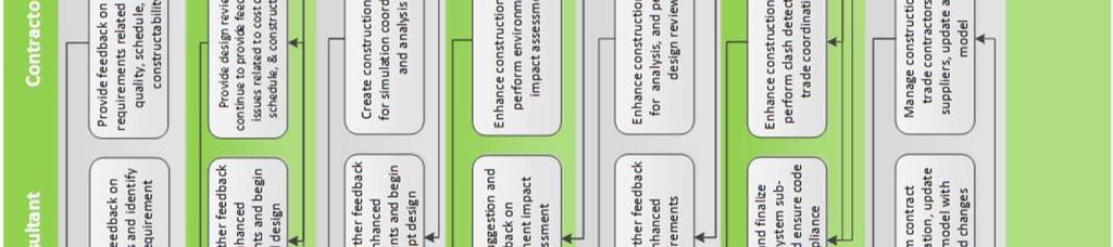
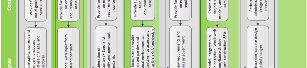
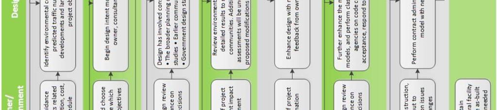
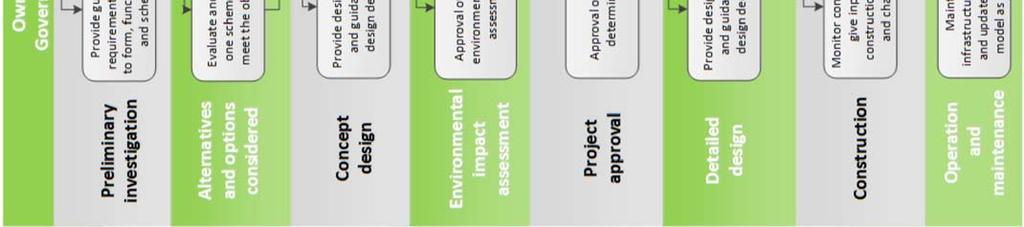
47 Example: Cross disciplinary model design in a road project 47


48 6 BIM relevant issues 6.1 Different BIM models Ideally, a construc on project would u lise a single BIM model used by designers, contractors, subcontractors and fabricators for all purposes. Each party could access the model at will, adding content that all others could immediately u lise. The reality is that for many years there will rarely be a single BIM model. The architect may have its design model, each engineer may have an analysis model for its discipline, the contractor may have a construc on simula on model and the fabricator its shop drawing or fabrica on model. Interoperability the sharing of informa on between these different models is cri cal to the collabora ve use of BIM, by assuring that each model consistently represents the same building. However, current technologies, and levels of BIM adop on, do not yet allow seamless coordina on between different BIM models. The use of mul ple models undermines the collabora ve use of BIM and prevents project par es from reaping the full benefits of BIM's capabili es. 6.2 Duplication Some firms may not be able to afford BIM and therefore tradi onal drawings will s ll have to be produced to manage the downward supply chain. It is also likely that smaller contractors will not have access to the digital BIM model onsite. Further, most authori es require tradi onal drawings for planning and building regula on approval. This causes duplica on and creates the poten al for ambiguity. If, for example, the contractual documents are in 2D but the project is designed in a BIM model which will take precedence? 48

49 6.3 Ownership In most projects, ownership of the BIM model is likely to be retained by the owner of the building. However, ownership of the data contained within the BIM model itself is a separate issue. Such data is likely to be wide ranging, and contribu ons will come from a variety of different par cipants. For example, there is likely to be design data, cost data, design processes, tables, databases and graphical informa on. Different laws will govern each of these rights. Enhanced regard to intellectual property provisions is especially important since the BIM model will not only show the results of patented processes and designs, the BIM will actually know the building codes, algorithms and applicable engineering principles. It is this informa on which the system applies to enable the model of the building to be manipulated and updated. Therefore design par cipants will be required to depart much more intellectual property on a BIM project than they are tradi onally used to. The terms of any assignment or licensing of intellectual property rights will therefore be of great concern to all design par cipants. Increased integra on and collabora on also means that there will be complex layers of intellectual property, provided by different design par cipants, which will be difficult to iden fy and reverse engineer. 6.4 Designer's liability exposure In a collabora ve BIM model many par es contribute to the design. Crucial details embedded in the design may be provided not by design professionals, but by specialty subcontractors or consultants. In addi on, BIM so ware is designed to react to changes in the model, by modifying elements of the design affected by a change. These circumstances increase the poten al liability exposure of design professionals who use BIM collabora vely and risk assuming overall model responsibility. 6.5 Professional terms of engagement Terms of engagement for all of the project team will need to be considered and dra ed to reflect the collabora ve nature of BIM and to ensure that responsibili es, du es and services are aligned. Communica on and methods of working will need to be outlined to enable those who are not in a direct contractual rela onship to work together in order to deliver the project in the integrated and collabora ve spirit required by BIM. Provisions on the input of data, limita on of liability and defining the role of any BIM model manager will also be crucial. 49
50 6.6 Risk profile The risk profile for construc on projects and project par cipants will change with use of a BIM model and a collabora ve, integrated approach. Measures will need to be taken to mi gate any increased areas of risk. This may require insurance, indemni es, changes to contracts and/or changes to policies and procedures. A balance will need to be struck between the need for fluid collabora on between par es on the one hand and the need to precisely define responsibility to manage the changed risk profiles on the other. 6.7 Mindset and approach BIM will completely change the way that designers approach the design process. The level of informa on contained within a BIM model requires collabora on between different par cipants at an early stage to establish the ini al framework and incorporate the level of detail required. More hours will be spent during the design and less in produc on. 6.8 Information technology BIM places increased reliance upon informa on technology. With this reliance comes the need for specific precau ons such as careful control of access rights and recording of audit trails. Technical support facili es, firewall limita ons, bandwidth limits, corrup on of data and compa bility issues are amongst the other concerns that need to be considered. The BIM model will be the core of the project and just one error in it can be very costly. Unlike the tradi onal approach, with plans that can be checked against one another, BIM plans are generated from the model and reflect the same data. This may allow small miscalcula ons, which can later lead to big problems that are difficult to spot. 6.9 Cost BIM models will require significant investment from those across the industry. There will be the direct cost of the so ware and hardware but also indirect costs such as training and obtaining suitable bandwidth to handle BIM data exchange. Given the level of investment necessary, the industry will take a cost benefit analysis to decide on adop on Owner Owners are likely to pay for the opera on and management of the BIM, for example, appoin ng an informa on or BIM model manager. However, the owner stands to benefit most financially from BIM usage with both construc on and opera onal savings. 50
.")


51 6.11 Designers Designers will have to spend significant amounts on purchasing so ware, licences, hardware and training staff. There will also be costs incurred from obtaining insurance (with poten ally high premiums given the collabora ve nature of BIM and increased risk of collec ve design). However, designers will benefit from advanced design features, such as clash deten on and value engineering tools. BIM also has a proven track record as a marke ng tool, which provides a clear commercial advantage in any bid process Contractors In a collabora ve BIM model many par es contribute to the design. Crucial details embedded in the design may be provided not by design professionals, but by specialty subcontractors or consultants. In addi on, BIM so ware is designed to react to changes in the model, by modifying elements of the design affected by a change. These circumstances increase the poten al liability exposure of design professionals who use BIM collabora vely and risk assuming overall model responsibly Level of detail Contractors are likely to want more detail included within the model so that clashes, delays and extensions of me will be avoided during construc on. However, with more detail added during the design phase, design costs will increase and the model will become more difficult to manage and operate. Determining the balance of detail, and how much reliance can be placed upon it, will therefore be a crucial issue to be nego ated between all project par cipants. 51


52 6.14 Contractual implications Historically most contracts are bipar te agreements. BIM has the poten al to substan ally alter the rela onships between par es and blend their roles and responsibility. Risks will need to be allocated ra onally; based on the benefits a party will be receiving from BIM, the ability of the party to control the risks, and the ability to absorb risks through insurance or some other means. As par es journey along the path to fully integrated BIM, bilateral contracts, with BIM addendums or protocols, may become unsuitable and collabora ve mul party contracts could poten ally become more appropriate. Payment mechanisms may also need to be changed to reflect the fact that BIM projects will become front loaded. Pain / gain mechanisms for collabora ng par cipants may also be favoured. The contract will also have to define the status of the BIM model and deal with post handover ma ers such as lifecycle management and data capture Insurance / bond markets Few insurance companies currently offer BIM related products. The rarity of BIM projects to date means that uncertain es remain about its benefits and risks. Insurers are likely to increasingly offer BIM insurance policies but un l it is clear what risks are involved premiums are likely to be high. Uncertainty is also likely to impact upon the bond market un l BIM becomes more commonplace. 52


53 7 Case Studies 53


54 7.1 Case Study Upgrade of Great Eastern Highway, Western Australia Project Background This case study describes the Great Eastern Highway (GEH) upgrade, which was delivered by the City East Alliance. The alliance partners were Main Roads WA, Leighton Contractors and GHD as the designer. This is a major access route between the Perth Domes c Airport and the Graham Farmer Freeway Major Stakeholders Main Roads WA Project (client), City East Alliance (MRWA, GHD, Leighton Contractors and NRW), Swan River Trust, Aboriginal Heritage, and European Heritage Project Description The upgrade consisted of expanding 4.2km of the highway from four to six lanes between Kooyong Road and the Tonkin Highway. It also included the construc on of a central median along the length of the upgraded sec on, upgrading major intersec ons to allow for turning movements, bus lanes, onroad cycling facili es and a con nuous pedestrian path. The project aims to ease conges on along the highway by increasing its capacity by 70%, from 50,000 to 85,000 vehicles a day. It will also improve access to the airport and surrounding areas, improve safety for local residents and other users of the highway, and deliver be er facili es for pedestrians and cyclists. The upgrade also included two variable message sign boards, CCTV cameras at each of the major signalised intersec ons and a fibre backbone running the length of the median. These systems will be used by Main Roads WA Traffic Opera ons Centre to help manage traffic conges on. 54

 Addi onally,")
55 7.1.4 BIM Tools AutoCAD, AutoCAD Civil 3D, Navisworks, 12d and MX BIM Technical Analysis (Pros) BIM 3D, 4D and 5D modellings were adopted in the virtual design and construc on of the project. In addi on, other BIM uses were also applied in the project such as: Constructability Reviews Traffic Impact Simula ons 3D Coordina on Engineering Analysis Clash Deten on Product Master Data Field Survey BIM Technical Analysis (Cons) The scope of project ended a er construc on and the maintenance was handled by another stakeholder. However, some areas of BIM uses could be improved and developed in the future during the construc on stage, such as : Field Design Changes Mobile Progress Claiming Site Logis cs (JIT) Addi onally, there is a very strong level of interest to adopt other BIM uses during opera on and maintenance of the project, such as: Road Management Maintenance of Traffic Geospa al Issue Tracking Equipment Machine Control Virtual Project Scheduling Work Zone Safety Planning Virtual Work Planning Virtual Cost Repor ng Visual Progress Repor ng Quality Issue Tracking and Repor ng Product Inspec on and Tes ng. 55
 shows the project can be viewed on screen and acted as the single point of truth during the project s construc on.")


56 7.1.7 Process and Benefits The screen shot of the Web Viewer below (Fig. 13) shows the project can be viewed on screen and acted as the single point of truth during the project s construc on. The Viewer is available to the public over the web to view the current and planned works and be er understand what will be occurring in their neighbourhood as this project has impacted hundreds of land holders and business. Fig. 13 Web based Interface The benefits in terms of accurate and current visualisa on for Stakeholder Consulta on are substan al. The project team have access via tablets and ipads to an enhanced Version containing addi onal layers of informa on. It has been synchronised on a monthly basis with the 3D Navisworks model and updated u lising the GIS and Navisworks Data (Fig 14 below). Fig. 14 Different level of Details in BIM From the quality aspects, the construc on engineers were aware of where they should not dig and the designer could physically see the space and obstruc ons to design around. Fig. 15 illustrates the accurate informa on in the model compared to the as built construc on. 56


57 Fig. 15 Comparison of as built versus as planned Process Challenges A few challenges were encountered in the project. These were: project. They were required to be relocated The limited project delivery meframe required the construc on of the new road before all u li es could be relocated. As such, cri cal construc on ac vi es such as earthworks cut and fill, retaining wall construc on and street ligh ng installa on had to occur in and around live services There were dense u lity corridors, which were containing over 80km of exis ng cabling, pipe and conduit within the 4km Maintaining access to all land owners and businesses for the length of the project High ini al investment and start up cost was a significant concern to the management team Loca on of exis ng u li es and buried infrastructure Conclusion The project was completed successfully in terms of cost, me and quality of works by applying numerous BIM uses in the project. Some areas of BIM uses were highlighted for future use, par cularly during the construc on and opera on stages. Furthermore, it is worth no ng that the construc on cost on Great Eastern Highway for u lity reloca ons alone was about $8 million per kilometre, with reduc ons from the ini al es mates of about $2 million per kilometre a ributable to efficiencies iden fied in the model. The project has involved a total of million man hours with 0 lost me injury (LTIFR =0). The project has achieved a na onal HSE Award for the Leighton Group. Overall the project ran $7 million under the targeted budget and 3 months ahead of the targeted comple on date, of which the total saving contributed to by the model was $24 million or equivalent to 14% of the total project cost of $175 million. 57
58 7.2 Case Study Moreton Bay Rail Project, Queensland Project Summary The Queensland Transport and Main Roads State Planning Program is based on analysis of current and future integrated passenger transport op ons. Investment decisions must take into account the challenges of distance in order to deliver quality transport networks for a growing popula on. Use of the Regional Queensland Passenger Transport Network Plan assists with the iden fica on of appropriate network services for designated regions. The Moreton Bay region of Queensland is the third largest local government area in Australia and is also one of the fastest growing areas in Australia. Popula on growth is expected to con nue over the next 15 years which will cause a significant transporta on problem if the use of private cars grows at the same pace. Known as the Moreton Bay Rail (MBR), work began in 2013 on an integrated public transport corridor for the region with vehicle, cycle and pedestrian access. The corridor includes a 12.6km doubletrack rail line to provide a safe and reliable transport network. Currently over 80% of Moreton Bay residents travel to work in a private vehicle. It is expected that nearly 6,000 people will use the Moreton Bay train daily. Because MBR will significantly improve public transport in the area, it will provide an incen ve for people to make the switch to public transport. Current driving me is one hour from Kippa Ring to the CBD in Brisbane. While rail service will be upgraded, an addi onal effect is to reduce conges on on the road network for journeys that can t be made using public transport. In addi on the rail corridor provides a proven method to reduce carbon emissions; every full train equates to removing 600 cars from the road network. The MBR project is funded in part by the Na on Building Program of the Australian Government. The Queensland Government and Moreton Bay Regional Council are co funding the $1.47billion project to bring to frui on a visionary project that began through land acquisi on in the 1980s. Finalisa on of alignment and sta on sites concluded with the design development and crea on of the TrackStar Alliance in 2013 to deliver the project. TrackStar Alliance is an integrated infrastructure delivery business that harnesses the skills of four business partners with Queensland Transport and Main Roads; Hassell, Thiess, Aurecon and AECOM. Each of the private sector partners provides specific skills for this complex project: Contractor: Thiess Architects & Urban Designers: Hassell Technical Services: Aurecon Engineers: AECOM 58

 to Anzac Avenue in Kippa Ring. h ps:// www.moretonbay.qld.go v.")
59 7.2.2 Project Overview Location The Moreton Bay Rail (MBR) project involves construc on of a new 12.6km dual heavy track passenger rail line between Lawnton and Kippa Ring that includes six new railway sta ons. The integrated transport passenger rail corridor is located approximately 23 kilometres north of the Brisbane CBD within the local government area of Moreton Bay Regional Council. The corridor extends eastward from Petrie railway sta on (27.5 km by rail from Central Sta on, Brisbane) to Anzac Avenue in Kippa Ring. h ps:// v.au/uploadedfiles/ common/projects/ moreton bay rail link/ MBRL Map.pdf Key Features Rail corridor The completed Moreton Bay Rail link will be 12.6km of dual heavy track and structures. Sta ons The six new sta ons: Kallangur, Murrumba Downs, Mango Hill, Mango Hill East (previously called Kinsellas Road), Rothwell and Kippa Ring. All sta ons will provide full passenger services: 175m long side pla orms, walkways, cket offices, wai ng facili es, park and ride facili es and bus/train interchanges. Road and rail bridges MBR construc on includes 22 major bridge structures. In some loca ons, such as the Bruce Highway and Brays Road in Murrumba Downs, a rail bridge will be built over the exis ng road. At Kinsellas Road East a new road bridge has been built over the rail line. Cycling and walking (paths and facili es) MBR will provide an opportunity to upgrade user shared pedestrian and cycling links within the Moreton Bay region specifically related to new rail sta on access. 59
, Queensland Government ($300million) and Moreton Bay Regional Council ($105million).")

60 Moving 371,000 cubic metres of materials from the Petrie sta on site. These materials were re used at other loca ons along the rail corridor to build up the rail embankment. Cost The $1.47billion required for the project is provided jointly by the Australian Government ($742million), Queensland Government ($300million) and Moreton Bay Regional Council ($105million). The Queensland Government, through Queensland Transport and Main Roads, is delivering the project on behalf of the three funding partners. The Queensland Government has also contributed land valued at $120million to the project. Duration 2011: Develop detailed design, procurement for construc on and acquisi on of remaining proper es : Preconstruc on ac vi es and construc on 2016: Finalise construc on and commence rail services (weather permi ng) Design, Management and BIM During the last 20 years different IT companies have invested in so ware to obtain integrated environments for effec ve collabora on between architects, engineers and contactors. Development of these tools is based on the premise that collabora on between all project par cipants through ITC will enhance construc on process and increase work efficiency. This focus has encouraged modelbased (3D) design solu ons including objectoriented BIM environments. Designers for all phases of construc on projects use a range of so ware with specific func ons. These occupa on specific so ware preferences, as well as the organisa onal cycle of ITC upgrades, are major drivers for the global effort to provide a unified means of informa on exchange within each construc on project. Currently, integra ng 2D with approaches to 3D models is driving so ware development and project collabora on. 60
61 Table 3: Examples of the differences between the software used by the civil engineers at QTMR (string based) and the architects at Hassell (object based). Potential Use Integration Type of Process Type of Object Responsibility Tool 2D 3D BIM 2D 3D BIM FM Road/Rail Geometric Modelling Planning & Design Systems (String Based Design) Roundabout Civil Engineer Roadside objects including: walls, embankments, and service poles. Civil Engineer ARNDTA: QTMR Numerical Design Tool Main Roads 12d Customisation Clash Detection Interoperability 2D drawings Export via IFC to Navisworks Also forms QTMR BIM AutoCAD D drawings AutoCAD Map D drawings Main Roads Auto- 2D drawings Manual drafting Concepts Computer Aided Drafting (Object based Design) Rail stations Architect SketchUp Revit Visualisation 2-way with Revit, multiple iterations 2D drawings Accepts IFC for clash detection (worked better than Navisworks) Import into Navisworks Navisworks Import from Revit & IFC No export 61


62 Hassell 3D model of the Rothwell Sta on and Landscape for concept communica on As the client and eventual owner of the MBR all documents for the project should ul mately be available to Queensland Transport and Main Roads. Their customised BIM system is the 12d product. A significant number of construc on design and implementa on so ware tools have been researched and developed specifically for QTMR. Because projects have standard requirements such as road signage or ligh ng, all contractors are required to use the QTMR so ware for some parts of a project to ensure that documenta on is compa ble with their customised 12d system. Hassell use SketchUp and Rhino/3D Max for early phases of design. Aurecon have been using Navisworks for suppor ng BIM enabled design since AECOM uses AutoCAD 3D and all these partners have BIM modelling exper se with Revit. The MBR project design has two dis nc ve components as indicated in the accompanying table on the previous page. The first relates to the buildings and architectural elements that use object based BIM solu ons as described above. However, these object based models do not fit easily into the 12d string based modelling pla orm preferred by QTMR. The second project component relates to geometric elements including railway embankment alignments, the access roads, bridges, landscaping and the pedestrian walkways. In this domain, string based modelling solu ons, such as 12d are considered essen al because working with object based BIM solu ons is painstakingly inefficient. For instance, Alignment strings in 12d provide independent horizontal and ver cal geometry and are created and edited interac vely on plan and sec on views. Integra on of models generated from the two different approaches does take place within Navisworks via IFC export or direct export. This process has proven to be challenging (in terms of me and skills availability), but the MBR project team are effec vely using IFC object data in the Navisworks so ware for project interoperability. However, a major shortcoming remains the lack of two way processing once the models are in Navisworks. Station design is an essential ingredient in making public transport attractive to users and the community and getting the design for each station right is a key priority for the Moreton Bay Rail project team. 62


 with a 3D model is a valuable communica on tool.")
63 Benefits of BIM Easy to communicate a concept using a 3D object based model Iden fica on of incompa ble fixed 3D objects (clash detec on) in a working model is more effec ve for project progress Integra on of required design elements modelled in QTMR 2D so ware The variety of processes and products that are required in the construc on of the MBR means that problems will arise and solu ons need to be found. Building informa on modelling (BIM) is a solu on beneficial during the design stages. Revit and AutoCad, as authoring tools, create 3D models that are great problem solvers for clash detec on. This type of modelling means being able to see three dimensional walls, floors, windows and columns which aids detailing and especially design changes. Because building objects have been the focus of much of the BIM development during the last 15 years, architectural skills in BIM are the most advanced. The object based model design process flow for MBR is: Conceptual model in SketchUp Design development in Revit Developing model returns to SketchUp for visualisa on clash detec on) within Navisworks Providing project consultants (project managers, es mators, engineers, contractors) with a 3D model is a valuable communica on tool. The value of clash detec on analysis at an early stage assists with the evolu on of co ordinated project documenta on. An important feature of the MBR transport corridor is the six new sta ons. Each sta on is strategically located to connect the rail corridor to their wider community with the aim of providing evidence of the benefits of public transport. Each of the six sta ons will have a unique design to set it within an urban growth precinct. BIM is used by Hassell to design the sta ons and integrate them into the road, rail, cycle and pedestrian systems. At the same me efficiencies were obtained by standardising elements of each of the sta ons such as pla orm design, exterior sta on overhangs, and ramps to parking areas. A con nuing itera ve process to integrate changes into an acceptable developed model Developed 3D model analysed (e.g. 63
 for the project components that use models generated with string based so ware.")

64 A major shortcoming of Navisworks 3D modelling is the lack of two way processing once the models are in Navisworks. This makes working with object based BIM solu ons risky (due to possible loss of data) for the project components that use models generated with string based so ware. The object based models also do not fit easily into the 12d string based modelling pla orm preferred by QTMR. providers, focused on compe ve advantage, aim to be ahead of the pack with the latest IT solu ons. These differences of purpose and organisa onal construc on management systems are converging with increasing use of increasingly effec ve 3D modelled construc on solu ons. As the client QTMR has the need to provide safe public transport systems based on research led standards that are embedded in their opera ng and management systems. Private Informa on for this case study was obtained from: h p:// projects/moreton Bay Rail.aspx#projectplan. 64


 and the Ministry for Culture and Heritage (MCH).")
65 7.3 Case Study Memorial Park Underpass, New Zealand Project Summary The Na onal War Memorial in Wellington, New Zealand commemorates the more than 300,000 New Zealanders who have served their country and the 30,000 who died in this effort. The Carillon tower was the first sec on of the Na onal War Memorial that opened in It commanded a dominant posi on overlooking the city and was easily visible from most areas of the capital. However urban growth has diminished its iconic posi on. To regain pride of place, a Memorial Precinct to mark the centenary of the First World War is currently under construc on. It includes the Carillion, the Hall of Memories, the Tomb of the Unknown Warrior and a new Park and Ceremonial Plaza. Precinct construc on requires pu ng a sec on of State Highway One (Buckle Street between Tasman, Tory and Taranaki Streets) underground with the Memorial Precinct on the top. The development is collabora ve between New Zealand Transport Agency (NZTA) and the Ministry for Culture and Heritage (MCH). Announcement of the project coincided with passage of legisla on allowing NZTA to accelerate construc on of the Underpass to allow the necessary me for the Ministry for Culture and Heritage to complete the Park for services on 25 April 2015, Anzac Day. The Memorial Park Underpass Project scope is outlined in four well defined phases: Phase one site prepara on for the tunnel Phase two dig the trench Phase three construct the tunnel Phase four build the park on top of the tunnel It was es mated that development of the Park would cost NZ$12 million. Wellington City Council agreed to contribute $2.11 million towards that the cost. The balance of the funds for the Park development is the responsibility of the Ministry of Culture and Heritage. The NZTA ini ally earmarked $80 million for the transport works. 65


66 The Australian and New Zealand Army Corps (ANZAC) formed in 1916 (troops from the First Australian Imperial Force and 1st New Zealand Expedi onary Force) fought in Gallipoli. This major ba le is commemorated in both countries on 25 April, ANZAC DAY. The countries con nue to share memorials and services. The Australian contribu on of AU$5 million is for a dedicated Australian Memorial to be placed on the Ceremonial Plaza. Design and Construc on for the project is by The Memorial Park Alliance that includes both government agencies, NZTA and MCH and four private providers: Downer, HEB Construc on, Tonkin & Taylor and URS. The Memorial Park Alliance deliverables are the three lane underpass for NZTA and the Memorial Park on top of the underpass for MCH. However three major constraints place pressure on project delivery: An 18 month deadline, ANZAC day 25 April 2015 for WWI commemora on ceremonies Works are in the CBD of Wellington, New Zealand, a major earthquake zone Significant heritage in the construc on site, over and above the War Memorials Project Overview The Na onal War Memorial Park and Underpass Project will result in an iconic interna onal War Memorial in the city of Wellington, the capital of New Zealand. Location The underpass is a reinforced concrete structure approximately 180m long. The structure will allow the 3 lanes of State Highway 1 to be placed underground from Sussex St to Taranaki St, a main traffic route in the CBD of Wellington. Construc on of the tunnel creates the needed ground level space to develop the Na onal War Memorial Park especially an enlarged Ceremonial Plaza that will be built above the underpass. At the same me the underpass is considered part of the Memorial Precinct. 66 Urban Design conceptual model of Memorial Park

 Construc on of the tunnel involves two components: basic road design and build for construc on of a basic box (slab, walls, roof) using tradi onal construc on methods; earthquake")
67 Key Features Surrounding roadworks Diversion of Buckle Street, re design for entry and exit to tunnel, necessary temporary traffic, cycle and pedestrian travel arrangements. Underground services Up grading and reloca ng underground city services including storm water for water table stability. Trench Demoli on of current roadways. Massive earth works: digging a 180m trench and hauling soil to other city loca ons. Construc on and placement of temporary and permanent stabilisa on walls and piles. Tunnel (underpass) Construc on of the tunnel involves two components: basic road design and build for construc on of a basic box (slab, walls, roof) using tradi onal construc on methods; earthquake proofing. Park Re design and re surface park area; terracing; plan ng trees & shrubs; adding rock features & sculptures including Australian s ck men (on the roof of the underpass); res ng place for Crèche. Heritage Buckle street archaeology, dealing with buried treasure; moving, renova on, earthquake proofing Home of Compassion Crèche built in Preserva on of 100 year old brick Wellington City sewer and Mount Cook Police Sta on and Barracks built in Engineering sec on of tunnel and piles 67


68 Cost The New Zealand Transport Agency (NZTA) originally earmarked $80m for the undergrounding of Buckle Street. However, the ght me frame for comple on and the inner city loca on constraints has meant that costs have increased as deadlines were met, while dealing with unforeseen problems. layer of weathered greywacke rock. A er tes ng a number of op ons, the choice was to hammer rather than vibrate the piles into the ground a costly op on requiring two very large cranes. The September 2014 es mate is in excess of $120m. For example, in the Autumn of 2013 the steel sheet piles that were to be used for the trench retaining wall near the Mount Cook Police Barracks (built in 1893), hit a Duration The New Zealand Parliament passed the Na onal War Memorial Park (Pukeahu) Empowering Act 2012 to assist NZTA make the vision of a Na onal War Memorial Precinct a reality inside a ght meframe of 18 months. Phase 1. Site Prepara on: August 2012 January 2013 Designing and planning for construc on of the tunnel and the road diversion. The first opera on on site was to divert a sec on of State Highway 1 (Buckle Street) to a temporary posi on enabling work on the underpass to begin. The major part of the diversion was to remove, update or stabilise the necessary city services that were located underground where the trench was to be dug. Examples of services: underground stormwater, water main, sewage, gas, electricity and telecommunica ons pipes. In addi on, 6.5km of new pipes were required (including new valves and steel pipe connected to the 100 year old water main under Tory Street) to maintain water table stability. 68


 were embedded 15 metres into the ground.")
69 Phase 2. Dig the Trench: February 2013 September 2013 Construc on of the trench was in fact site prepara on for the underpass. Mass haul: To make a hole 300 metres long, 18 metres wide and at its deepest point 12 metres deep required moving dirt 32,281 cubic metres of soil (for use in suburban development). This amount of mass haul equated to 3,586 truck and trailer loads, all moving through busy CBD streets. The dimensions of the hole created sufficient space for both temporary and permanent retaining walls. Temporary trench retaining walls: The walls were necessary to create the construc on site for the tunnel. Temporary kingposts and mber walls protected the ground and the workers in the trench. The wall was made up of 285 kingposts reaching 15 metres into the ground plus 14,381 mber posts slo ed between the kingposts. Permanent retaining walls: A 90m long permanent steel sheet pile retaining wall was needed in front of the Mount Cook Police Barracks and Tasman Gardens Apartments. These interlocking steel sheet piles (225) were embedded 15 metres into the ground. This protects the founda ons of these heritage buildings that are close to the tunnel. The importance of the wall is to prevent loss of the water table because of the addi on of a large structure at the bo om of the hill. Ground anchors: Earth quake zones require specialised building methods. To ensure stability of the permanent retaining wall required 558 anchors (each 13 metres long) to be installed sideways into the ground. They are ed into both the kingpost walls and sheet pile walls for added strength. Working on the trench 69

70 Australian Memorial The Australian Memorial was designed by Australian architectural firm Tonkin Zulaikha Greer. It features 15 columns made from rugged red sandstone as symbolic of the 'Red Centre' of Australia. The columns will be surrounded by Australian eucalyptus trees, a typical Australian landscape. centre) in its final res ng place. The Crèche was built in 1914 for Mother Suzanne Aubert and has been recently placed on the New Zealand Historic Places Trust Register as the first purpose built crèche in the country. Re design and re surfacing of the memorial area includes: terracing and plan ng trees & shrubs; addi on of rock features & sculptures including the Australian s ck men; loca ng the Home of Compassion Crèche (a child care BIM Capability and Capacity View of underground services during Park construc on (October 2014) The Project Management team has the responsibility of ensuring comple on of the scope of the project as defined by the clients New Zealand Transit Agency, the New Zealand Ministry of Culture and Heritage, Wellington City Council, and the Australian Office of War Memorials. During the last 20 years, different IT companies have invested in so ware development to enable effec ve collabora on between architects, engineers and contractors through an integrated modelling process. Development of these tools is based on the premise that collabora on between all project par cipants through ICT will enhance the construc on process and increase work efficiency. Pla orm and so ware developers have played a vital role in crea ng the evolving BIM environment based on the concept of 3D interoperable modelling. Integra ng 3D modelling capability and capacity is the necessary founda on for comple ng the complex construc on projects of the 21 st century. In order to meet their obliga ons, a team of designers for specific phases and specific processes used a range of so ware for dedicated project components. To complete the scope of the project, within the site and me constraints, the Memorial Park Alliance project team u lised 3D modelling for the design and management of some project components. This report focuses on the BIM applica on to this brown field project, specifically the applica on for underground services. 70

 funnel through the construc on site.")


71 Underground Services (water, telecommunica ons, gas and electricity) Benefits of BIM To fit together a complex integra on of infrastructure and services within extremely ght loca on constraints To solve the complexity of the geographic and physical constraints of exis ng and new services To provide visualisa on of the design resolu on The geography of the city of Wellington means that all services including electricity are placed underground in the CBD. Because the CBD is on the harbour, many services (especially storm water) funnel through the construc on site. These factors place a major constraint on the project services work: services cannot be interrupted because they link to a variety of suburbs, necessita ng con nuous business and residen al use. Thus, the complexity of the task for the Underground Services team: to relocate, preserve, up grade or install new services. Tonkin & Taylor contributed their BIM exper se in Underground Services design and management to the Alliance. Their capability includes the possession of knowledge and skills to integrate differing types of 3D modelling so ware. over non gravity systems. Throughout the project the Underground Services model is expected to be constantly changing. Changes result from a rigorous quality control of both the model and the site. The model was designed with AutoCAD Civil3D. This so ware supports con nuous design changes, genera ng documenta on and working collabora vely. Civil3D models are able to integrate infrastructure data from 12d and MX and provide detailed informa on for construc on workers onsite. The most important feature of the 3D visualisa on is for design resolu on of the mul ple layers of services and visualisa on of the limita ons of space. Reloca ng old underground services before digging the trench The first step for the Underground Services team was to ensure a complete model of current services as the AS IS 3D model for all phases of the project. To do this they dug test pits to locate the mul ple services. The data from these sites became the founda on for their AS IS model. The AS IS model provides important decision making informa on such as ensuring loca ng gravity system 71

 func onality.")
72 An example of a cri cal design resolu on was to fit the tunnel between the fragile 100 year old horse shoe shaped brick and mortar sewer and the other services which were located over this structure. Services for stormwater and telecommunica ons had to remain under the tunnel roof. 100 year old sewer under Tory Street, Wellington, New Zealand The effec veness of the con nually changing 3D model was because the Taylor & Tokin Underground Services team had both experience using BIM enabled so ware, as well a sufficient number of successful experiences in solving construc on problems using the 3D design resolu on (commonly called clash detec on) func onality. Indeed an important aspect of their success is based on understanding the common limita ons of both 2D and 3D so ware modelling and design detail processes. New valve to connect with the 100 year old sewer Challenges of Enabling BIM Public road and rail infrastructure project so ware interoperability The Memorial Park Underpass project has been designed and managed by 60 designers, construc on managers and support staff. The construc on site constraints were embedded in a number of local community requirements: con nued use of the local primary school; minimising disrup on of Wellington airport traffic; minimising inconvenience for residents close to the construc on site; as well as con nual adapta on of local CBD traffic routes. All of these constraints required a significant amount of flexibility to deal with unknown problems. The capacity to solve these problems, especially within the 18 month project comple on deadline was dependent on ITC for design resolu on. BIM technologies have been presented as a solu on to all problems within the construc on industry. However, challenges remain. BIM has many defini ons (depending on occupa on and so ware claims) making transfer of 3D models on complex construc on projects risky. While buildings are modelled in object based so ware, transport infrastructure design construc on models use string based so ware. 72


73 Currently 12d is the standard modelling system used by Australian and New Zealand publicly funded transport authori es. Many transport infrastructure projects involve alignments to the curvature of earth s surface (especially over long distances). Therefore it makes sense to use 3D modelling so ware that provides visualisa on of geographic contours. visualisa on for modelling the replacement, removal and reloca on of the underground services (water, gas, telecommunica ons, electrical) on this complex inner city iconic heritage project. However, integra ng their model into the string based models of other components of the infrastructure project was always too difficult. The Underground Services team was able to create and use object based Anzac Day, 25 April 1932: 50,000 people stand in silence for the dedica on of the Carillon on Mount Cook the first of the Na onal War Memorial buildings. Source: Alexander Turnbull Library; Ref: 1/ G; Photo: Sydney Charles Smith Informa on for this case study was obtained from: h p:// park/index.html?r=1 Addi onal informa on was provided by members of the Memorial Park Alliance. 73
74 7.4 Case Study The Design of Perth s Light Rail Network, Project Summary Western Australia Metro Area Express, or MAX, is Perth s proposed 22 km light rail network that will run from Mirrabooka in the north to the CBD, before spli ng into two branches to Victoria Park Transfer Sta on in the east (via the Causeway) and to QEII Medical Centre in the west (via West Perth). This visionary project will introduce a new era of public transport in Perth, suppor ng the city s transforma on by providing a frequent, high capacity service in the inner north and central west and eastern suburbs of Perth. Essen ally a modern tram system using electric rail cars, the new light rail system is quiet and efficient and will be built on exis ng streets but largely separated from general traffic. The project is a catalyst for city change, being coordinated with land use planning with the inten on of s mula ng revitalisa on and new developments along the proposed alignment. Due to cri cal State budget pressures, the State Government has deferred the MAX Light Rail project for three years, which will see overall comple on of the project by late The MAX Light Rail project is a transforma onal project, and the State Government is commi ed to delivering the project in full. The revised meframe will see a call for tenders in early 2018, construc on commencing in 2019, with first services running by late BIM has been used in several ways on the MAX Light Rail project but mainly in the design stage of the project at the moment Major Stakeholders The Integrated Services Team (IST) established for the project included AECOM, as part of the Joint Venture and the Western Australia Department of Transport Project Description The IST func oned in a collabora ve and innova ve way to successfully deliver the Business Case including the following project disciplines; preliminary design (including systems), traffic network opera ons modelling, environmental approvals and sustainability, land use planning and stakeholder and community management Project Delivery Method The proposed project delivery method is Design Bid Build. The State Government has placed the project on hold. 74

75 75

76 7.4.5 BIM Tools and Uses Infrastructure So ware 12d model Provided the pla orm for the produc on of the exis ng feature survey and the proposed road design model, including pla orms and retaining walls and the drainage assessment. Autodesk AutoCAD Civil 3D Provided the pla orm for the produc on of the exis ng in ground and above ground service model. Bentley Rail Track Provided the pla orm for the produc on of the proposed rail design model. GIS So ware Esri Provided the pla orm for the produc on of mapping all of exis ng heritage, exis ng environmental, building, exis ng services, and proposed design. repor ng tool. Traffic So ware: LinSig Provided the pla orm for the Intersec on traffic analysis. Traffic So ware: SIDRA 6 Provided the pla orm for the isolated intersec ons analysis. Traffic So ware: STEM Provided the pla orm for the overall traffic Analysis and future traffic volume modelling. Traffic So ware: Commuter micro simula on Provided the pla orm for the overall traffic volume Analysis and future traffic volume modelling. Clashes Detec on / MTO / 4d Sequencing using Autodesk Navisworks Provided the pla orm for the coordina on of all models, review tools, clashes and cost BIM Technical Analysis (Pros) BIM uses were adopted only at the design stage of the project, such as: Land Use and Transporta on Planning Public Informa on and Communica on Constructability Reviews Traffic Impact Simula ons Rule based Model Valida on Clash Deten on Quan ty Take off GIS tracking 3D Coordina on Engineering Analysis 76
77 7.4.7 BIM Model Development and Process The details of the model could not clearly be defined by the LOD Specifica on as the nature of the project is Civil infrastructure. Nevertheless, the LOD Specifica on sec on G. Building Site works could be used as a base for clarifying the details of the model. It could be projected that most elements modelled were at the average level of LOD 200. For elements that fell out of this parameter would be categorised under sec on G fundamental LOD defini ons were applied. The DoT or PTA is the owner of the model, the Intellectual property and the method of informa on management in crea ng the model. Yet, the poli cal sensi veness of the project was observed in the project, which all employees were required to be bound to a cabinet confiden al agreement. There were some structured policies that only allowed approved users to access the informa on on the server and project folders. The GIS web viewer had a user login with addi onal security to limit only defined IP address access, allowing only access within predefined loca ons. The model was also audited regularly through an internal process to comply with the defined quality systems BIM Collaboration and Workflow The proposed 22km light rail network had a magnitude of exis ng informa on. Fig. 16 shows the overall BIM workflow. The exis ng informa on could be categorised into two main data sets, namely, (a) physical data on the exis ng condi ons, and (b) spa al data on the flows of exis ng vehicle and human traffic condi ons. The physical exis ng informa on were derived from exis ng records and survey. The 22km nework was surveyed using a tradi onal method of feature survey and a laser scan method. Both survey methods provided the informa on for the exis ng condi ons required in the model development. It would iden fy areas or elements as posing risks to the project and to be communicated clearly for future risk mi ga on. The exis ng survey informa on data set was provided and synchronised in Infrastructure So ware 12d model. The survey informa on was exchanged with other so ware pla orms via Landxml. Landxml provided the common pla orm to exchange simple (non volumetric) informa on between pla orms. 77


78 Fig. 16 LRT BIM Workflow The point cloud informa on data set was provided in Leica LAS format. The point cloud data was processed using Autodesk Recap to refine and index the point informa on into the federated model and broken into key areas which required surface /volumetric model informa on The exis ng u li es informa on data set was obtained from mul ple asset and government agencies. It included the GIS asset records and spa al mapping systems. A.S.5488: Classifica on of subsurface u lity informa on SUI was applied to the exis ng u lity informa on to provide a uniform data structure. The processed informa on with the schema from AS5488 was stored in the Ersi Shape GIS data base. Bentley Subsurface u li es engineering so ware was adopted for crea ng and maintaining the data form SUE. The data would be in the shape file format and to be displayed in the project GIS view. Landxml was also used to categorise and provide the physical/spa al/ visual data. 78


; and produc on of civil/structural backgrounds.")


79 7.4.9 Conclusion BIM has been used in several ways on the proposed MAX Light Rail project, including building intelligent databases of key project components and systems; overlaying of exis ng services, rail, road, electrical system, 22km of point cloud laser scanning and civil/structural elements to iden fy and eliminate conflicts (clash detec on); and produc on of civil/structural backgrounds. Virtual clash detec on eliminates field construc on changes that are iden fied as costly and provide challenges to the project schedule and overall budget. Two dimensional drawings were extracted from the BIM model, which was developed with all of these factors in mind, for use in the business case. 79


80 7.5 Case Study Auckland City Rail Link, New Zealand Project Summary The City Rail Link (CRL) will extend Auckland s passenger rail system past Britomart to connect to the exis ng regional rail network at Mt Eden. Britomart will become a through sta on with new sta ons near Aotea Square and Karangahape Road, and a redeveloped sta on at Mount Eden. The current phase is to undertake preliminary design for use in procurement and detailed design of an Enabling Works package. The CRL will use twin 3.4km long tunnels up to 33 metres below the city centre streets. It is es mated it will take five and a half years to build at a cost of NZ$2.5 billion when inflated to 2024 prices Major Stakeholders Table 4 shows the major stakeholders in the project. Table 4: Major stakeholders Stakeholder Name Auckland City Council Auckland Transport Aurecon Aurecon Jasmax/Grimshaw Mo McDonald Role Funder Client Principal Technical Advisor Principal Consultant Rail Systems, Structure, Civil, Tunnelling, U li es, Alignment, Survey Architecture Building Structures and Services 80
 and Karangahape Road (33m), will be developed and")


81 7.5.3 Project Description Two new underground sta ons at Aotea (11m depth) and Karangahape Road (33m), will be developed and Mount Eden Sta on will be redeveloped as illustrated in Fig. 17. It will involve cut and cover construc on along Albert Street and at Eden Terrace. The majority of the construc on will be using a tunnel boring machine (TBM), which is 7.5 metres in diameter. It will excavate about 1 million cubic meters of spoil. Eighty eight subterranean proper es will be affected and benefited by the tunnels. Fig. 17 Design of the Project Project Delivery Method The project was a Reference Design Project, where Aurecon was engaged as the Principal Technical Advisor. Future engagements are expected to be Design Build with Contractor based design teams. 81
82 7.5.5 BIM Tools and Uses At the design stage, six so ware packages were used. Table 5 shows the details for the so ware. Table 5: BIM tools BIM Package Version Build/Service Pack File Format Revit _2115(x64)/.RVT Update Release 2 Civil 3D 3D.DWG AutoCAD.DWG Bentley MX SS DGN 12d VERSION 10 K.12DA Navisworks Simulate NWD, NWC, NWF BIM Technical Analysis (Pros) BIM uses were adopted only at the design stage of the project, such as: Public Informa on and Communica on Constructability Reviews Traffic Impact Simula ons 3D Coordina on Engineering Analysis Clash Detec on Quan ty Take off 82

83 7.5.7 BIM Technical Analysis (Cons) Public Informa on and Communica on Constructability Reviews Traffic Impact Simula ons Engineering Analysis Clash Detec on Quan ty Take off 3D Coordina on BIM Model Development and Process The aim is to see BIM used as the primary drawing produc on environment and not as a retrospec ve tool, so that the func onality of BIM can be used to assist the design coordina on and op misa on. This will involve the establishment and execu on of collabora ve processes using 3D modelling tools, and the exchange and coordina on of digital models to achieve the following objec ves: Significantly reduce clashes between the design intent of different systems (for example, hydraulic services and structural elements) to establish geometric presence and to pass the following benefits to the design and construc on team: Foster confidence in the design intent Shorten construc on me compared with tradi onal construc on processes Minimise re work and varia ons during and construc on phases Enhance project quality and workers safety on site All drawings which are relevant to defining the project in terms of its physical envelope and spa al coordina on will be produced in a 3D CAD format with Building Informa on Modelling (BIM) capability. This includes sta on and tunnel layouts, sta on and tunnel building services, major equipment layouts, major sta on and tunnel components, etc. Drawings which are not relevant to this spa al aspect need not be developed to this standard but where relevant shall be capable of being cross referenced or input as schedules to the overall BIM model. These excluded drawings may comprise system architecture and schema cs, reinforcement drawings, schedules, explanatory notes, etc. Overall, IP and ownership remain with the consultants put with an implied license used by the client. The LOD for the Reference Design Phase will be minimum LOD
84 7.5.9 BIM Roles and Responsibilities Table 6 shows the BIM roles and responsibili es in the project. Table 6: Roles and Responsibili es Defined Role BIM Manager Responsibility in Business Management Process development Coordinate BIM use on project, determine schedule of use, sharing ac vi es, quality control, modelling responsibili es and documenta on in business management BIM Responsibility Oversight, Management, Execu on and Model Exchange Lead BIM Coordinator Implemen ng BIM Manager instruc ons Assist BIM Manager with Reference Design Team. Represen ng BIM Manager. Architectural Design Execu on formulate with BIM Team Manager. Map BIM use for architectural design. Modelling and Review, Model Exchange. Structural Team Engineering formulate with BIM Manager. Map BIM use for structural simula on and Modelling and Review, Model Exchange. documenta on. MEP Team Engineering Formulate with BIM Manager. Map BIM use for simula on and documenta on Modelling and Review, Model Exchange. Alignment Team Support. Provide data in the specified exchange format Data development and integra on Civil Team Support. Provide data in the specified exchange format Data development and integra on U li es Team Support. Provide data in the specified exchange format Data development and integra on BIM Collaboration and Workflow Coordina on mee ngs were held weekly with model managers coordina ng their respec ve areas and maintaining an issues or coordina on register that was tracked weekly with percentage completes, un l they were closed out completely. Fig. 18 illustrates the workflow of the design stage. Tuesday Thursday Fig. 18 BIM Workflow Problems with Model Week 1 Architects Issue Models Consultants Review Coordina on Mee ng Consultants Implement Week 2 Consultants Issue Models Architect Reviews Coordina on Mee ng Architects Implement Problems with Model 84


85 Conclusion This is a large project, which will last for five and a half years and be built at a cost of $2.5 billion. The consultants were engaged with very li le defini on of what was required of BIM for the project. The project has developed an interest into BIM uses in Public Informa on and Communica on, and Constructability Reviews, which two methods could be improved further in the design stage. 85
86 Appendix A Existing BIM Guidelines Country Organisa on BIM guidelines & standards Year Descrip on/objec ve Australia Australian and New Zealand Revit Standards NATSPEC Australia Mechanical Contractors' Associa on Australian and New Zealand Revit Standards NATSPEC Na onal BIM Guide BIM MEP AUS Prac ce Establish minimum compliance requirements for Revit content shared or sold throughout Australia and New Zealand. Document Revit content crea on best prac ses. Establish a more extensive collec on of shared parameters. Establish a list of object subcategories. Develop discipline specific requirements for Revit content. To assist clients, consultants and stakeholders to clarify their BIM requirements for projects in a na onally consistent manner. Address the following barriers that are currently preven ng the effec ve take up and use of BIM within Australia: Significant me and cost burdens involved in customising BIM modelling so ware to suit Australian design and construc on requirements. Lack of industry standards around BIM MEP documenta on. Poor considera on of the requirements for IPD. Limited BIM Project Management and file management exper se within the industry." Coopera ve Research Centre for Construc on Innova on Massachuse s Ins tute of Technology Department of Facili es Na onal Guidelines and Case Studies for Digital Modelling MIT CAD & BIM Guidelines To assist in and promote the adop on of BIM technologies in the Australian building and construc on industry, and try to avoid the uncertainty and disparate approaches that created inefficiencies with the implementa on of 2D CAD over the past three decades. These guidelines are issued to promote the development of electronic drawings and models suitable for use in the MIT Department of Facili es CAD and BIM environment. USA Georgia Tech Facili es Management Indiana University Architect's Office and Engineering Services Georgia Tech BIM Requirements & Guidelines for Architects, Engineers and Contractors BIM Guidelines & Standards for Architects, Engineers, and Contractors 2011 This document will allow all stakeholders to weigh the importance of each requirement on a per project basis. Through this collabora ve effort, a final project based set of requirements and corresponding BIM Execu on Plan will be issued based on what level of BIM proficiency necessary for a given project Standards for AEC. University of Washington Capital Projects Office A achment G University of Washington CAD and BIM Standards 2012 Standards for A/E project drawings. This includes CAD and BIM drawing standards, PDF requirements, and the schedule of documents submi als for Owner s compliance review. The A/E may request a compliance review at any me during the Project. 86
87 University of Southern California Facili es Management Services Los Angeles Community College District BIM Guidelines 2012 BIM Standard 2011 Guidelines for design bid build contracts. This document defines the Design and Construc on scope of work and deliverables for using BIM on new USC construc on projects, major renova ons and other projects as required by USC, based on a Design Bid Build form of Contract. Standards for design build projects. The LACCD BIM Standards for Design Build Projects have been developed to define a process and establish requirements, procedures and protocol for the u lisa on of BIM in the various stages of our design build projects. San Diego Community College District BIM Standards for Architects, Engineers & Contractors 2012 Standards for Architects, Engineers & Contractors The principle objec ve of incorpora ng BIM is to improve the quality of the design solu ons and op mise the exchange of informa on between par es The Pennsylvania State University College of the Desert, California BIM Planning Guide for Facility Owners 2012 BIM GUIDE 2011 Guide for facility owners. The Guide is wri en for facility owners who operate and maintain facili es, it can also provide value to those owners who procure facili es as well as other non owner organisa ons wishing to adopt BIM. Using Building Informa on Modelling for the design, construc on, and management of all its future projects. This guide will cover the overall process of developing a BIM project workflow and the basic understanding of College of the Desert s standard. USA Na onal Ins tute of Building Science buildingsmart alliance Na onal BIM Standard 2012 NBIMS establishes standard defini ons for building informa on exchanges to support cri cal business contexts using standard seman cs and ontologies to be implemented in so ware United States General Services Administra on Na onal 3D 4D BIM Program 2007 A guide intended for GSA associates and consultants engaging in BIM prac ces for the design of new construc on and major modernisa on projects for GSA American Ins tute of Architects E BIM Protocol 2008 This exhibit establishes the protocols, expected levels of development, and authorised uses of Building Informa on Models on this project and assigns specific responsibility for the development of each Model Element to a defined Level of Development at each Project phase. Where a provision in this Exhibit conflicts with a provision in the Agreement into which this Exhibit is incorporated, the provision in this Exhibit will prevail. Associated General Contractors of America The Contractor's Guide to BIM 2009 to generally introduce the subject and provide an outline of the how to for ge ng started United States Air Force Centre for Engineering and the Environment Capital Investment Management ATTACHMENT F BIM Requirement 2012 Requirement for design build/firm fixed price contract 87
88 United States Army Corps of Engineers City of San Antonio Capital Improvements Management Services New York City Department of Design + Construc on Roadmap for Life Cycle BIM BIM Development Criteria and Standards for Design & Construc on Projects BIM Guidelines 2012 The scope of this plan is to focus on the implementa on of BIM in the U.S. Army Corps of Engineer's civil works and military construc on business processes, including the process for working with the USACE Architectural Engineering Construc on industry partners and so ware vendors Standards for Design & Construc on Project developed to define a process and establish requirements, procedures, and protocol for the u lisa on of BIM in the various stages of CoSA s design and construc on building projects elements and systems to use as a tool to more efficiently manage, maintain, and renovate the facility for the life cycle of the building The BIM guide considers the end use of the model for mul ple client agencies, allowing qualified and authorized client agency representa ves to review the ways in which the BIM may facilitate their ongoing building opera on and maintenance protocols, and tailor their agency requirement and standards to leverage the enhanced capabili es provide by BIM for building O&M. New York School Construc on Authority BIM Guidelines and Standards for Architects and Engineers 2012 Guidelines and Standards for Architects and Engineers Use BIM and related so ware products as a tool, which would, amongst other things, assist in the development of coordinated Contract Documents for Capacity construc on Projects USA US Veterans Affairs The Port Authority of NY & NJ Engineering Department VA BIM guide 2010 EAD (E/A Design Division) BIM Standard Manual 2012 This guidance shall apply to design and construc on by the architects, engineers, other consultants, and contractors hired for those projects by VA. The Port Authority of NY & NJ BIM Standard Manual describes the processes and procedures required for the prepara on and submission of BIM Models for Port Authority of NY & NJ projects. State of Ohio Facili es Construc on Commission BIM Protocol 2012 Establish a common methodology for communica ng owner s expecta ons for the level of detail and types of data contained in a building informa on model. Establish minimum building informa on modelling expecta ons that reflect current industry capabili es while incorpora ng processes that provide immediate value to owners. Encourage further industry adop on of BIM to allow owners to receive increased benefit from the technology State of Texas, Texas Facili es Commission Professional Service Provider Guidelines and Standards 2010 Guidelines and Standards for Architectural and Engineering This document applies to all TFC projects contracted on or a er the Edit Date indicated in the header above. State of Wisconsin Department of Administra on, Division of State DSF BIM Guidelines & Standards for ARCHITECTS and 2009 Guidelines & Standards for ARCHITECTS and ENGINEERS Georgia State Financing and Investment GSFIC BIM Guide Series 01: 2013 The purpose of this guide is to aid Architects and Engineers (A/Es) 88 in their Building Informa on Modelling (BIM) efforts related to design and construc on of GSFIC managed projects. This release
89 Denmark Erhvervsstyrelsen (Na onal Agency for Enterprise and Construc on) Det Digitale Byggeri (Digital Construc on) 2007 A guide made of 4 components: 3D CAD Manual, 3D Working Method, Project Agreement and Layer and Object Structures Spain Generalitat Valenciana (Valencia Regional Government) FIDE Spanish buildingsmart Finland Yleiset etomallivaa mukset 2012 The guidelines mainly focuses on architecture and engineer design. Finland Senaa Kiinteistot (aka Senate Proper es) Senate Proper es: BIM Requirements 2007 General opera onal procedures in BIM projects and detailed general requirements of BIM models focuses on the design phase Norway Boligprodusentene BoligBIM 2011 Statsbygg Statsbygg BIM Manual 2012 Intended to be a prac cal aid for those who perform the project planning for residen al dwellings. A full scale IFC test documen ng experiences gained on a collabora ve project Netherlands Rijksgebouwendienst (Ministry of the Interior and Kingdom Rela ons) Rgd BIM Standard 2012 A BIM Framework consis ng of seventeen orthogonal dimensions that describe in general the Building Informa on Modelling world cons tu ng a "Way of Thinking about BIM AEC (UK) BIM Standard for AEC industry in UK 2011 It is aimed at providing a base star ng point for a unified BIM standard that can easily be adopted as is or developed and adapted for implementa on within projects that have specific requirements for the structuring of their BIM data. This document intends to provide pla orm independent guidelines for BIM for designers. AEC (UK) AEC (UK )BIM Protocol 2012 It focuses primarily on adapta on of those standards for prac cal and efficient applica on of BIM, par cularly at the design stages of a project United Kingdom Construc on Industry Council Best Prac ce Guide for Professional Indemnity Insurance when using BIM and, Outline Scope of Services 2013 The aim of this best prac ce guide is to support the construc on industry s take up of Level 2 Building Informa on Modelling, by summarising the key areas of risk which Professional Indemnity ( PI ) insurers associate with level 2 BIM and what you can do about those risks as a prudent insured. Specialist Engineering First Steps to Contractors BIM Academy at the University of Northumbria. Na onal Specialist Contractors Council BIM Competence: A Guide for Specialist Contractors The purpose of this guidance document is to acquaint firms with the steps they need to take to become comfortable using Level 2 BIM that is, developing and sharing projectrelated data in a 3D format with other par es.
 at different stages of a project.")
90 Singapore Building and Construc on Authority Singapore BIM Guide 2012 It is a reference guide that outlines the roles and responsibili es of project members when using Building Informa on Modelling (BIM) at different stages of a project. It is used as a reference guide for the development of a BIM Execu on Plan, which will be agreed between the Employer and project members, for the successful implementa on of a BIM project. CORENET e submission System CORENET BIM e submission Guidelines 2010 Architectural, structural and MEP guidelines were published Hong Kong The Hong Kong Ins tute of Building Informa on Modelling BIM Project Specifica on 2011 This BIM Standard is intended to be used to define the scope of work for a BIM process, the responsibili es of the project par cipants and the deliverables from the BIM Process for the overall benefit of the project and the owner. 90
91 Appendix B Existing BIM Tools Tool Vendor Capabili es Revit Autodesk 1. Including Revit Architecture, Revit Structure and Revit MEP; 2. Parametric components: Use intelligent building components to improve design accuracy; 3. Bidirec onal associa vity: Any change in your design is automa cally reflected throughout your model; 4. Work sharing: Mul ple users can simultaneously work on the same intelligent building model; 5. Construc on modelling: Improve insight into constructability of building elements. AECOsim Bentley 1. Including Architectural Design, Structural Engineering, Mechanical Engineering and Electrical Engineering; 2. Interdisciplinary modelling environment to integrate design and documenta on workflows, eliminate barriers between disciplines, and shorten learning curves; 3. Immersive interac on to create and interact with 3D models, 2D designs, as well as innova ve hyper modelling to integrate and access all available project informa on; 4. Trusted deliverables produc on to generate precise drawings and documenta on, informa onrich 3D PDFs, and 3D plots; 5. Performance simula on to evaluate and explore designs through lifelike rendering and anima on, genera ve design, and built in clash detec on; 6. Comprehensive breadth and depth to integrate engineering geometry and data, including point clouds, from an unmatched range of CAD and BIM so ware and engineering formats like IFC and DWG ArchiCAD Graphiso 1. Priority Based Connec ons; 2. Industry first Background Processing; 3. Extended IFC Model View Defini ons; 4. Open Interface to External BIM Component Providers; 5. Integrated Design, Visualisa on and Analysis Workflow Tekla Structure Trimble 1. For Concrete Contractors: Model, plan and pour concrete; 2. For Steel Fabricators: Manage detailing, fabrica on and erec on of all steel structures; 3. For Precast Fabricators: Op mise the en re precast workflow from bidding to delivery; 4. For Electricity U li es: Manage electricity networks and perform mul ple distribu on process; 5. For Rebar Fabricators: Manage prefabrica on of rebar and reduce total cost and me. SketchUp Pro Trimble 1. Start by drawing lines and shapes, push and pull surfaces to turn them into 3D forms; 2. Changes to your model are reflected automa cally in Layout; 3. Having the world s biggest repository of free 3D models; 4. Massive plugins provide extra features such as sustainable analysis. Digital Project Gehry Technologies 1. Including Designer, Manager and Extensions; 2. Designer: Genera ve surfaces design, Parametric 3D surfaces, Free style surface modelling (NURBS), Design to fabrica on, Revision tracking and part comparison, and Advanced solids modelling; 3. Manager: Real me sec oning, Measure object dimensions, Quan ty take offs, Access volume measurements, and Project team collabora on; 4. Extensions: Import Primavera ac vi es, MEP/Systems rou ng, 3D models for curved shapes, Advanced parametric control, and STL and STEP integra on. 91
92 Rhino Rhinoceros 1. Edi ng complex models is faster and easier with Direct sub object manipula on and Thin wall shelling ; 2. Easier to create 2D drawings and illustra ons for every discipline in every nota on system and visual style used around the world; 3. Rhino models can be accurate enough for and accessible to all the processes (e.g. fabrica on, manufacturing, or construc on processes) involved in a design becoming a reality; 4. Robust mesh import, export, crea on, and edi ng tools; Ca a Dassault 1. 3D Design : Industrial design, Class A, Reverse Engineering; 2. Mechanical Engineering: Op mising end to end design to manufacturing process; 3. Electrical & Fluid Systems Design: Managing product complexity; 4. System Engineering: Bringing products to life; 5. Experience Modelling: Providing clear dashboards, powerful analysis capabili es, and flexible searching. E3D AVEVA 1. Design solu on: Mul discipline 3D plant design, Intui ve 3D graphics, User friendly interface, Local Customiza on; 2. Reduce business risk: Mul discipline 3D plant design, Built in quality and compliance; 3. Integra on: Built in quality and compliance, Integrated 3D, engineering and schema c data; 4. High Performance: Integrated 3D, engineering and schema c data, High performance in large networks. PDMS AVEVA 1. A fully interac ve, color shaded 3D plant design environment, Hundreds of designers can work concurrently on a project ; 2. Designers progressively create a highly intelligent 3D design by selec ng and posi oning parametric components from an extensive catalogue; 3. Clash checking and configurable integrity checking rules ; 4. A configurable Status Management func on provides visual highligh ng and clear repor ng of design maturity status of PDMS objects; 5. Highly configurable, automa c genera on of a wide range of reports and drawings direct from the PDMS database ; 6. AVEVA PDMS is highly configurable and includes both a powerful programmable macro language (PML) and a.net API to customize the system and automate tasks. SmartPlant Enterprise Intergraph 1. 3D Modelling & Visualisa on : Providing an integrated design environment for plant construc on to save project me and increase produc on efficiency; 2. Engineering & Schema cs : Designed to drive plant op misa on, the rule driven environment prevents engineering errors for increasing data quality and consistency across tasks; 3. Informa on Management : maximizes efficiency for industrial and manufacturing plant maintenance and provides plant opera on solu ons; 4. Procurement, Fabrica on & Construc on : materials specifica on and change management through procurement and tracking to inventories, forecast, and material issuing. Intergraph lowers labour costs throughout engineering, procurement, and plant construc on; 5. The SmartPlant Enterprise family includes 27 products for the specific project purpose. 92
93 12D Model 12D 1. 12d Model is a powerful terrain modelling, surveying and civil engineering so ware package. 2. It allows quick and high quality produc on in a wide variety of projects including: Road and Highways, Ports and Dredging, Land Development, Airport Infrastructure Rail, Mining Infrastructure, Drainage, Sewer and U li es Surveying, Oil and Gas, Construc on Rivers, Dams and Hydrology Environmental 3. Using 12d Model's screen menus and fast interac ve graphics, the user effortlessly moves through a design. 4. With 12d Model's powerful design capabili es, difficult surveying and civil design tasks can be easily visualised and completed d Model includes a powerful programming language, which allows users to build their own op ons, from the extensive 12d Model programming library d Model has been specifically designed for easy use. It is ideal for use at all stages of projects, and is par cularly useful for large route selec on and corridor studies. 93
94 Existing 4D Simulation Tools Navisworks ConstructSim Vendor Autodesk Bentley Capabili es 1. Simulate 4D construc on schedules and logis cs; 2. Generate object oriented anima on; 3. Develop compelling 3D anima ons and imagery. 1. Comprehend the full complexity of modern construc on projects during ini al planning through the Virtual Construc on Model; 2. Improved constructability analysis and advanced planning and coordina on between engineering office and site field office; 3. Design out unsafe construc on prac ces; 4. Reduce me to create work packages while increasing accuracy; 5. Ability to match available labour to work packages; 6. Support Agile/Lean/WFP construc on methods; 7. Plan ahead to reduce construc on bo lenecks; 8. Reduce rework and out of sequence work; 9. Streamline turnover and commissioning planning. Synchro Synchro 1. Enable full round trip data synchroniza on (Import, Export, Synchronize To and From) to facilitate work flows for both upstream and downstream delivery processes; 2. 4D spa al coordina on for sta c and dynamic analysis and conflict resolu on; 3. Deliver tradi onal project scheduling, repor ng, custom 4D anima on, advanced AVI produc on; 4. Provide EVA (earned value analysis) and cost loaded schedule for including variable cost analysis for decision support and for planned and actual cost analysis; 5. Database module enables advanced systems integra on, reusable project and component libraries, and support for the ever increasing data in the BIM model to enterprise data management envisioned by the industry. Vico Trimble 1. Loca ons are used to perform loca on based quan ty takeoff which is the input for loca on based schedule planning; 2. Adop ng flow line scheduling to op mise the construc on schedule; 3. On site produc on control: Measuring work put in place by loca on and comparing actuals to planned helps Supers see poten al conflicts far in advance; 4. 4D BIM scheduling movies makes it easy for audiences (Owners, trades, teams) to see how the building will come together. DELMIA Dassault 1. Plan, with comprehensive 3D process and resource planning tools to create and op mise build to order and lean produc on manufacturing systems; 2. Simulate, with tools to virtually define and op mise manufacturing assets concurrently with manufacturing planning; 3. Operate an accurate virtual produc on system to track real me produc on ac vi es, perform schedule changes, launch new programs and introduce model changeovers, and schedule maintenance opera ons. NET Player AVEVA 1. Easily understood display of project status and construc on sequence via the 3D model for monitoring cri cal tasks; 2. Simula on and review of construc on sequences in 4D; 3. Playback controls enable the user to start, stop, loop and step through the anima on; 4. Rrapid compila on of produc on or construc on progress and status reports. 94
95 Existing 5D Simulation Tools Vendor Capabilities Navisworks Autodesk 1. Simulate 5D construction schedules and logistics; 2. Model-based quantity takeoff. itwo RIB 1. Combine traditional construction planning and trail-blazing 5D planning in one software suite; 2. Resource control through all project phases with end-to-end visual support; 3. Construction Process Integration heralds a new quality in the planning and building process; 4. Making important information transparent and complex contexts manageable. Vico Trimble 1. Location-based construction-caliber quantity take-off; 2. Project stakeholders can examine budget levers, the items which greatly influence a project's ability to stay on track and run powerful comparisons. CostX Exactal 1. Support 5D BIM using information from the model live-linked to user-defined rate libraries and workbooks- all within the one program; 2. A networked environment allows instantaneous information sharing with others working on the server; 3. Import of a multitude of drawing files and external rate information, and exports to a variety of formats, taking interoperability to a new level; 4. Unique revision tool identifies changes and automatically updates quantities; 5. Use in-built templates to import model data or easily create Model Maps to customize your BIM take-off. Innovaya Innovaya 1. Automatic Quantity Extraction and Estimation; 2. Intelligent Assembly/Item Take-off; 4. Completely Embracing MC2 and Timberline Estimating; 5. Intelligent Change Management; 6. Support for Effective Team Communication. 95
96 References 1. Australian and New Zealand Revit Standard, Australian and New Zealand Revit Standard Commitee: Australia. Available from: h p:// 2. NATSPEC Na onal BIM Guide, Construc on Informa on Systems Limited ABN : Australia. Available from: h ps:// bim.natspec.org/documents/natspecna onal bim guide 3. BIM MEPAUS Prac ce, Mechanical Contractors' Associa on: Australia. Available from: h p:// ini a ve/wp content/uploads/ sites/4/2016/04/bma ducted fan coil unitspecifica on pdf 4. Na onal Guidelines and Case Studies for Digital Modelling, Coopera ve Research Centre for Construc on Innova on: Australia. Available from: h p:// oninnova on.info/images/pdfs/ BIM_Guidelines_Book_191109_lores.pdf 5. MIT CAD & BIM Guidelines, MIT Campus Planning, Engineering, and Construc on: USA. Available from: h p://web.mit.edu/ facili es/maps/mit_cad_bim_guidelines.pdf 6. Georgia Tech BIM Requirements & Guidelines for Architects, Engineers and Contractors, Georgia Tech Facili es Management: USA. Available from: h p:// es.gatech.edu/files/ DC/2011_0815_GT_BIM_Requirements_v1.0. pdf 7. BIM Guidelines & Standards for Architects, Engineers, and Contractors, Indiana University Architect's Office and Engineering Services: USA. Available from: h p:// 20BIM%20Guidelines%20and% 20Standards.pdf 8. A achment G University of Washington CAD and BIM Standards, University of Washington Capital Projects Office: USA. Available from: h ps://cpd.uw.edu/cpo/sites/default/files/ file/cpo forms/consultants/a achment% 20G%20 %20%20UW%20CAD%20Standards% 20and%20Compliance%20BIM%20REV% _0.pdf 9. BIM Guidelines, University of Southern California Facili es Management Services: USA. Available from: h p://facili es.usc.edu/ uploads/documents/cas/ BIMGuidelines_VS1_6_2012.pdf 10. BIM Standard, Los Angeles Community College District: USA. Available from: h p:// bidders/ standards guidelines/quick search results? type=guidelines&category=6 11. BIM Standards for Architects, Engineers & Contractors, San Diego Community College District: USA. Available from: h p://propsn.sdccd.edu/cr/forms/sdccd%20 % 20Building%20Design%20Standards/02.% 20BIM%20Standards/SDCCD%20BIM% 20Standards%20Version%202.pdf 96


97 References 12. BIM Planning Guide for Facility Owners, The Pennsylvania State University: USA. Available from: h p://bim.psu.edu/resources/owner/ bim_planning_guide_for_facility_ownersversion_2.0.pdf 13. BIM GUIDE, College of the Desert: USA. Available from: h p://codbond.eispro.com/ uploads/ %20College%20of% 20the%20Desert%20BIM%20Guide.pdf 14. Na onal BIM Standard, Na onal Ins tute of Building Science USA. Available from: h ps:// onalbimstandard.org/ 15. Na onal 3D 4D BIM Program, United States General Services Administra on USA. Available from: h ps:// category/ E BIM Protocol, American Ins tute of Architects USA. Available from: h p:// cm /10290_contract_e202_cont RACT_ATTACHMENT _ PDF 17. The Contractor's Guide to BIM, Associated General Contractors of America: USA. Available from: h p:// thesis/por olios/2008/tjs288/research/ AGC_GuideToBIM.pdf 18. ATTACHMENT F BIM Requirement, United States Air Force Center for Engineering and the Environment Capital Investment Management USA. 19. Roadmap for Life Cycle BIM, United States Army Corps of Engineers USA. Available from: h p://codebim.com/wp content/ uploads/2013/06/erdc SR 12 2.pdf 20. BIM guide, Veterans Affairs: USA. Available from: h p:// l/bim/ BIMguide/downloads/VA BIM Guide.pdf 21. BIM Guidelines, Department of Design&Construc on: New York, USA. Available from: h p:// ddc/downloads/pdf/ DDC_BIM_Guidelines.pdf 22. BIM Guidelines and Standards for Architects and Engineers, New York City School Construc on Authority: USA. Available from: h p:// Guidelines BIM Development Criteria and Standards for Design & Construc on Projects Capital Improvements Management Services San Antonio, USA. Available from: h ps:// webapps.sanantonio.gov/rfplis ngs/ uploads% 5CRFQ_1223_ pdf 24. EAD (E/A Design Division) BIM Standard Manual, The Port Authority of NY & NJ Engineering Department: USA. Available from: h ps:// es/pdf/engineering consultantsead bim standard manua september 2012.pdf 25. BIM Protocol, State of Ohio Facili es Construc on Commission USA. Available from: h p://das.ohio.gov/portals/0/ DASDivisions/GeneralServices/SAO/pdf/SAO BIMProtocol.pdf 97
98 26. Professional Service Provider Guidelines and Standards, Texas Facili es Commission: Texas, USA. Available from: h p:// www. c.state.tx.us/divisions/facili es/prog/ construct/formsindex/01%20 %202012%20A E%20GUIDELINES.pdf 27. BIM Guidelines & Standards for ARCHITECTS and ENGINEERS Department of Administra on, Division of State Facili es: Wisconsin, USA. Available from: p:// doa p1380.wi.gov/master_spec/bim% 20Guidelines%20&%20Standards/BIM% 20Guidelines%20and%20Standards%20for% 20AE%20% %20Final%20DRAFT% pdf 28. BIM Guide, Georgia State Financing and Investment Commission: Georgia, USA. Available from: h ps://gsfic.georgia.gov/ sites/gsfic.georgia.gov/files/related_files/ document/gsfic%20bim%20guide%205.pdf 29. Det Digitale Byggeri (Digital Construc on), Erhvervsstyrelsen (Na onal Agency for Enterprise and Construc on): Denmark. Available from: h p:// fileadmin/templates/h /dokumenter/ ar kler/det_digitale_byggeri.pdf 30. VRG Formato Intercambio Datos Edificación (Building Data Exchange Format), Generalitat Valenciana (Valencia Regional Government): Spain. Available from: h p:// ycalidad en la edificacion/relacion dedocumentos reconocidos#drd Yleiset etomallivaa mukset 2012, buildingsmart Finland: Finland. Available from: h ps://buildingsmart.fi/wp content/ uploads/2016/11/ YTV2012_Taydentava_liite_TATE_Prosessiohj e.pdf 32. Senate Proper es: BIM Requirements, Senaa Kiinteistot (Senate Proper es): Finland. Available from: h ps:// /senateproper es 33. BoligBIM (BIM Manual), Boligprodusentene (Norwegian Home Builders Associa on): Norway. Available from: h p:// boligprodusentene.no/ge ile.php/ Dokumenter/BIM manual%202.0% 20Boligprodusentene.pdf 34. Statsbygg BIM Manual, Statsbygg: Norway. Available from: h p:// Files/publikasjoner/manualer/StatsbyggBIMmanual ver1 2 1eng pdf 35. Rgd BIM Standard, Rijksgebouwendienst (Ministry of the Interior and Kingdom Rela ons): The Netherlands. Available from: h ps:// documents/publica on/2014/07/08/rgd bimstandard v1.0.1 en v1.0_2 36. BIM Standard for AEC industry in UK, AEC (UK) commi ee: UK. Available from: h ps:// aecuk.wordpress.com/documents/ 37. AEC (UK) BIM Protocol: UK. Available from: h ps://aecuk.wordpress.com/documents/ 38. Best Prac ce Guide for Professional Indemnity Insurance when using BIM, Construc on Industry Council UK. Available from: h p://cic.org.uk/publica ons/ 39. First Steps to BIM Competence: A Guide for Specialist Contractors, Specialist Engineering Contractors' Group and BIM Academy at the University of Northumbria: UK. Available from: h ps:// media/1533/sec group bim updated 2014.pdf 40. Singapore BIM Guide, Building and Construc on Authority: Singapore. Available from: h ps:// media/586132/singapore BIM Guide_V2.pdf 41. CORENET e submission System, Construc on and Real Estate NETwork: Singapore. Available from: h ps:// general/corenet e submission system.aspx 98
99 42. BIM Project Specifica on, The Hong Kong Ins tute of Building Informa on Modelling: Hong Kong. Available from: h p:// content/ uploads/2011/08/hkibim_specifica on Rev3 0.pdf 43. Na onal Building Informa on Model Standard, Na onal Ins tute of Building Sciences: Washington, DC, USA. Available from: h ps:// page=standards 44. Building Informa on Modelling: A Framework for Collabora on. Construc on Law., 28: p buildingsmart, (2008) Interna onal. Model Industry Founda on Classes (IFC). Available from: h p:// tech.org/ specifica ons/ifc overview 46. NBIMS 2007, Available from: h p:// Markku Kiviniemi, Kris ina Sulankivi, Kalle Kähkönen, Tarja Mäkelä & Maija Leena Merivirta (2011), BIM based Safety Management and Communica on for Building Construc on, VTT RESEARCH NOTES BIM Project Execu on Planning Guide Version 2.0 (2010), Available from: H p:// Gerhard Gröger, Thomas H. Kolbe, Claus Nagel, Karl Heinz Häfele (2012), OGC City Geography Markup Language (CityGML) Encoding Standard (version 2.0.0), Open Geospa al Consor um, Available from: h p:// 50. Building Informa on Modelling, accessed: 23/08/2014. Available from: h ps:// law.com/en/topics/projects construc on/ projects and procurement/buildinginforma on modelling/ 99

100 Contact Professor Xiangyu Wang n.edu.au Project Leader Sustainable Built Environment Na onal Research Centre Cur n Director Australasian Joint Research Centre for Building Informa on Modelling Cur n University Kent Street Bentley WA 6102 GPO Box U1987 Perth WA 6845 Copyright informa on This publica on is copyright. This publica on may be reproduced provided appropriate acknowledgement is made to the authors, publisher and Australian Sustainable Built Environment Na onal Research Centre (SBEnrc). Printed April
Op mised inventory and produc on processes
 Inventory represents one of the largest expenses for many small and midsize businesses. Balancing accurate inventory management with cost-effec ve produc on is crucial for delivering on promise and keeping
A Small business guide on SaaS tool
 A Small business guide on SaaS tool ProcessManufacturingSoftware Introduc on In current mes, technology changes in the blink of an eye, leaving a las ng impact on the world of business. The organiza ons
Essen al so ware for managing your fleet
 ipad FleetWave CORE Essen al so ware for managing your fleet AWARDS2017 FLEET MANAGEMENT ISO/IEC 27001 BUREAU VERITAS Certification 1 Out of the box fleet management so ware With a compe ve entry-level
Principles for Credible and Effec ve Sustainability Standards Systems. ISEAL Credibility Principles
 Principles for Credible and Effec ve Sustainability Standards Systems ISEAL Credibility Principles June 2013 ISEAL Credibility Principles Introduc on Voluntary sustainability standards systems are market-based
ZTEso boosts China Mobile s IoT business growth and development
 ZTEso boosts China Mobile s IoT business growth and development ZTEso boosts China Mobile s IoT business growth and development Background & Challenges Voice and messaging revenues for Communica on Service
Multi-lingual Interface. Compliance
 Multi-lingual Interface All CAREDATA products can be customised to local language requirements with a choice of language options including English, French, Spanish, Arabic, Bhasa and many others. Compliance
Design Review Board Submi al Guidelines
 Design Review Board Submi al Guidelines The Design Review Board (DRB) is most effec ve when project design materials are prepared and presented to the DRB. Graphic material is generally preferred. Any
QUADRAM INSTITUTE BIOSCIENCE CAREER PATHWAYS
 QUADRAM INSTITUTE BIOSCIENCE CAREER PATHWAYS INTRODUCTION Quadram Ins tute Bioscience (QIB) is at the forefront of a new interface between food science, gut biology and health. It develops solu ons to
Transforming Enterprise Data Management Opera ons for a Global Asset Management firm
 Transforming Enterprise Data Management Opera ons for a Global Asset Management firm Hexaware provides consul ng and BAU EDM support for a Global Asset Management firm About the client Our client is a
Types of Design Professionals Caitlyn Trepess
 SMALL BUSINESS RESOURCES Types of Design Professionals Caitlyn Trepess The size (physical and construc on cost), complexity, scope, and loca on of a project will dictate which types of design professionals
Chapter 9: Congestion Management Process CHARLOTTE COUNTY PUNTA GORDA MPO 2035 LONG RANGE TRANSPORTATION PLAN
 Chapter 9: Congestion Management Process CHARLOTTE COUNTY PUNTA GORDA MPO 2035 LONG RANGE TRANSPORTATION PLAN CHARLOTTE COUNTY PUNTA GORDA MPO 2035 LONG RANGE TRANSPORTATION PLAN Conges on Management
Invoice Data Capture Software
 Invoice Data Capture Software A Buyers Guide For Finance Directors Produced By Clean Accounts An e-docs UK Brand Executive Summary New technology is driving organisa ons forward, improving sales, manufacturing
Capability Statement
 Capability Statement Hitech BioReactors Ltd, Spode House, 346 New Street, Biddulph Moor, Stoke-on-Trent, Staffordshire ST8 7NQ United Kingdom http://hitechinternatinal.co.uk/ Email: info@hitechinternational.co.uk,
The County of San Bernardino invites candidates for the position of: Project Director, Consortium IV
 The County of San Bernardino invites candidates for the position of: Project Director, Consortium IV Consor um IV The Mission of Consor um IV: Is to provide a client-based, fully integrated, on-line, user
SYDNEY S URBAN SERVICES LAND
 SYDNEY S URBAN SERVICES LAND ESTABLISHING A BASELINE PROVISION July 2017 Final report This publication was prepared for the Greater Sydney Commission for the purpose of regional and district planning.
Cross-Channel Marketing. Bringing brands and customers closer together
 Cross-Channel Marketing Bringing brands and customers closer together Your customers see a brand not a channel Today s customers are dynamic, empowered, and hyperconnected. They rely on a variety of devices,
Three Benefits of Digital Transformation for Transportation Management Services
 White Paper Three Benefits of Digital Transformation for Transportation Management Services by Abishek Bhat and Anuradha M O V E R C O M I N G L I M I T S Logis c complexi es and service-level expecta
The MEDxConnect Solu on. Mee ng the Challenges of Healthcare Virtualiza on
 The MEDxConnect Solu on Mee ng the Challenges of Healthcare Virtualiza on Meeting the Challenges of Healthcare Virtualization An innovative healthcare IT platform developed through a collaboration of Compressus
Governor s Council on Workforce Investment STRATEGIC PLAN
 Governor s Council on Workforce Investment 2018-2022 STRATEGIC PLAN Council on Workforce Investment 2018-2022 Strategic Plan Governor Sco Walker Room 115 East Wisconsin State Capitol Madison, WI 53703
Difference between Warehouse Management System (WMS) and Enterprise Resource Planning (ERP) System
 and Enterprise Resource Planning (ERP) System") Difference between Warehouse Management System (WMS) and Enterprise Resource Planning (ERP) System ProcessManufacturingSoftware Introduc on The terms Enterprise Resource Planning (ERP) and Warehouse Management
Difference between Warehouse Management System (WMS) and Enterprise Resource Planning (ERP) System ProcessManufacturingSoftware Introduc on The terms Enterprise Resource Planning (ERP) and Warehouse Management
8 ways ERP solutions extend the chemical industry's reach
 8 ways ERP solutions extend the chemical industry's reach ProcessManufacturingSoftware Introduc on The chemical manufacturing industry is one of the major contributors to the world economy, and while the
10 Key Digitization Benefits for
 ASSET MANAGEMENT 10 Key Digitization Benefits for Asset Management So, what is asset management? As per the ISO 55000 standards, Asset Management is co-ordinated ac vity t o r e a l i s e v a l u e f r
Aim of this Consulta on Event
 We are pleased to welcome you to view and comment on the proposal for the construc on of a New Energy Plant (NEP) to be located back from the corner of Inchyra Road and Bo ness Road Grangemouth, on the
Agile projects in a non-agile environment: What is your experience?
 Agile projects in a non-agile environment: What is your Date July 23, 2014 Author(s) The Agile Research Network Laura Plonka, Helen Sharp, Leonor Barroca and Dina Salah (The Open University, UK) Peggy
BIG DATA ANALYTICS WORKSHOP FOR MANAGERS March, Endorsed by
 BIG DATA ANALYTICS WORKSHOP FOR MANAGERS 10-12 March, 2019 Endorsed by BIG DATA ANALYTICS WORKSHOP FOR MANAGERS topics include: INTRODUCTION VISION & STRATEGY ARCHITECTURE & DATA APPLICATION DATA SCIENCE
White Paper. Forecasting s New Paradigm Improve accuracy and give be er guidance by involving all stakeholders in the process.
 May 2009 White Paper Forecasting s New Paradigm Improve accuracy and give be er guidance by involving all stakeholders in the process. Beagle Research Group, LLC 264 Greenbrook Drive Stoughton, MA 02072
Registra on Welcome Address and Opening Remarks. Is The USPTO Promo ng Innova on, Economic Growth And Global Compe veness?
 Sunday November 7th 11:00-1:30 1:30-1:45 Registra on Welcome Address and Opening Remarks 1:45-2:30 Is The USPTO Promo ng Innova on, Economic Growth And Global Compe veness? - Is the USPTO making it easier
QUALITY BY DESIGN IN PHARMACEUTICAL DEVELOPMENT. piramalpharmasolu ons.com
 QUALITY BY DESIGN IN PHARMACEUTICAL DEVELOPMENT piramalpharmasolu ons.com 02 INTRODUCTION Quality by design (QbD) is a systema c approach to product development that begins with predefined objec ves and
Diploma in procurement and supply Unit content guide
 Diploma in procurement and supply Unit content guide CIPS Group Easton House, Easton on the Hill, Stamford, Lincolnshire, PE9 3NZ, UK T +44 (0)1780 756777 F +44 (0)1780 751610 E info@cips.org CIPS Africa
Limi ng Heights for Nonstructural Standard and EQ Wall Studs
 TECH NOTE Publication 1, Version 1 March 2018 Limi ng Heights for Nonstructural Standard and EQ Wall Studs SUMMARY: This Technical Note addresses cold-formed steel studs in nonstructural interior wall
Modular Buildings Are Our Business
 COMPANY PROFILE Modular Buildings Are Our Business NT Link is conveniently based in the Northern Territory. We provide our clients, in all kind of industries a diverse and comprehensive range of essen
Harvest Cleaning Services LIMITED Ensuring Tidiness Up To Your Doorstep!
 COMPANY PROFILE Harvest Cleaning Services LIMITED Synopsis We excel in providing cleaning and hygiene solu ons for commercial and residen al spaces as well as Factories and Learning Ins tu ons. The scope
The History of CDW s begreen Program
 Our Commitment to the Environment 2018 1 The History of CDW s begreen Program CDW recognizes the need for responsible environmental management and conserva on of resources and has demonstrated its commitment
The History of CDW s begreen Program
 Our Commitment to the Environment 2019 1 The History of CDW s begreen Program CDW recognizes the need for responsible environmental management and conserva on of resources and has demonstrated its commitment
Certificate in procurement and supply opera ons Unit content guide
 Certificate in procurement and supply opera ons Unit content guide CIPS Group Easton House, Easton on the Hill, Stamford, Lincolnshire, PE9 3NZ, UK T +44 (0)1780 756777 F +44 (0)1780 751610 E info@cips.org
Kingdom of Swaziland. Ministry of Health. In-Service Training Guidelines
 Kingdom of Swaziland Ministry of Health In-Service Training Guidelines November 2015 PUBLICATION NOTICE A publica on of the Human Resources Unit, Ministry of Health. Any enquiries regarding this publica
CAPABILITY STATEMENT. s a f e t y q u a l i t y e n v i r o n m e n t
 CAPABILITY STATEMENT s a f e t y q u a l i t y e n v i r o n m e n t 1 3 0 0 1 2 3 6 4 7 / w w w. s a f e t y z o n e. n e t. a u Consultation Services O v e r v i e w SafetyZone consultancy service delivers
Demand & Supply Management: The next generation of forecasting
 Demand & Supply Management: The next generation of forecasting Thought Piece 2018 Incorporating Forecasting in Demand & Supply Planning Accuracy in forecas ng has the greatest impact on an organiza on
Embedded versus Marginal Cost of Service Studies
 T R P Melissa Whited (Synapse), with contribu ons from Paul Chernick (Resource Insight) and Jim Lazar (RAP) July 2017 In order to con nue to operate, a u lity must have an opportunity to recover its prudently
COMPANY PROFILE YEARS O F E XC E L L E N C E W I T H P R I D E. Committed to uphold integrity in the running of our Business C E L E B R AT I N G
 COMPANY PROFILE 2017 C E L E B R AT I N G YEARS O F E XC E L L E N C E W I T H P R I D E Committed to uphold integrity in the running of our Business THEWO ENGINEERING COMPANY PROFILE 2017 INDEX THEWO
MAKING DIGITAL TRANSFORMATION HAPPEN:
 MAKING DIGITAL TRANSFORMATION HAPPEN: BREAKING SILOS REQUIRES CULTURAL, BUDGETARY AND PORTFOLIO Stuart Williams stuart.williams@tbri.com Overview To achieve digital transforma on, enterprises and the so
Making Sochi Winter Olympics a Success for Social Media
 Making Sochi Winter Olympics a Success for Social Media Background Brief The Winter Olympics is one of the biggest spor ng events in the world, a rac ng the a en on across the globe. For a period of about
Ansoff Matrix. Source: adapted from Ansoff, 1957
 CIPS_Ansoff_Inn_Diff_Matrix_Poster_AW_v3_Layout 1 05/02/2016 12:10 Page 1 Ansoff Matrix Exis ng Markets PROTECT/BUILD PRODUCT DEVELOPMENT New Markets MARKET DEVELOPMENT DIVERSIFICATION Exis ng Products
Guide to the Occupa onal Health and Safety Act. Information for Workers
 Guide to the Occupa onal Health and Safety Act Information for Workers This guide provides practical information about the Occupational Health and Safety Act (OHS Act). A key part of a safe workplace is
Syracuse University Faculty Mentoring in a Networked World. Sec on 6: Social Network Theory and Mentoring
 Syracuse University Faculty Mentoring in a Networked World Sec on 6: Social Network Theory and Mentoring The complete version of the toolkit, each sec on and individual forms are available to download
STORMWATER & FLOOD MANAGEMENT MODEL. storm
 STORMWATER & FLOOD MANAGEMENT MODEL storm WHAT CAN xpstorm MODEL? Stormwater Management: Stormwater Master Plan Design Major/Minor or Dual Drainage Systems Watershed Master Plans 1D/2D Urban Flooding Deten
n this guide you can find enrollment instruc ons, as well as ps and tricks for establishing a great rela onship with your mentor.
 Mentee Guide ACOEP Mentor Program If you have any ques ons or concerns, contact Jaclyn Ronovsky, Member Services Assistant 312.445.5702 JRonovsky@acoep.org www.acoep.org Y our development as a physician
CIVIL ENGINEERING BENEFITS OF BIM. Helping Civil Engineers do more with BIM
 CIVIL ENGINEERING BENEFITS OF BIM Helping Civil Engineers do more with BIM CIVIL ENGINEERING BENEFITS OF BIM WHAT S INSIDE: 1 BENEFITS Keep constructability top-of-mind Improve project margins Make better
Executive Summary Regional Development Capacity Report
 Executive Summary Regional Development Capacity Report June 2012 2643 Gateway Drive State College, PA 16801 814-231-3050 www.crcog.net/planning EXECUTIVE SUMMARY The 2012 Regional Development Capacity
How do we know which benefits are statutory?
 1 Can help my business expand internationally? You can expand your business globally by plugging into the GPS eco-system. We help our clients expand globally to 150+ countries and are backed by a mix of
FIVE WAYS YOUR MOVE TO A BIM WORKFLOW PAYS OFF
 ARCHITECTURE & BUILDING ENGINEERING AEC COLLECTION EBOOK FIVE WAYS YOUR MOVE TO A BIM WORKFLOW PAYS OFF Get started > 01 02 03 04 05 DELIVER HIGHER- QUALITY WORK OPERATE MORE EFFICIENTLY EXPAND YOUR BILLABLE
A Framework to Increase SharePoint Adoption within your Organization
 White Paper A Framework to Increase SharePoint Adoption within your Organization by Abishek Bhat O V E R C O M I N G L I M I T S Microso SharePoint provides a vast number of capabili es that empower business
Making sure your policies are followed and your care plans are up-to-date, ensuring that everything is recorded properly and all within budget.
 WELCOME Thank you for your interest in our products These days, running a care home successfully could be compared to comple ng a complex jigsaw puzzle on a daily basis. Looking a er your residents, managing
P R O S T O D O C E L U CO K D odek E O s e F tyki ETHICS
 PROSTO DO CELU CODE OFetyki ETHICS Kodeks Vision PEKAES s vision is the crea on of a strong and modern logis cs and intermodal group offering the highest quality comprehensive logis cs services, which responds
YMCA YOUTH EMPOWERMENT IN ACTION
 E M O C WEL TO E G N A H C YMCA YOUTH EMPOWERMENT IN ACTION DEAR FRIEND, Welcome to change is the road map towards waking up the sleeping giant that is the YMCA as a collec ve coordinated body. In this
Project Portfolio Management Assessment
 Portfolio Management Assessment This report was prepared by Info-Tech Research Group for:, CIO March, 0 Por?olio Management Assessment Overall Score PPM Perceived Success These s express your percep-ons
CREDENTIALS
 CREDENTIALS WHO WE ARE Sheesh was born from the idea to create a unique and dis nc ve approach in offering our clients the quality and service required to make a no ceable difference. Having experience
Railston Interiors Brochure FACILITY SERVICES
 Railston Interiors Brochure FACILITY SERVICES We have presence in Sydney, Melbourne and Brisbane. HQ in Sydney. SYDNEY, AUSTRALIA SGB Facility Services 1/19 Underwood Avenue Botany NSW 2019 t. 1300 55
Fabricated Assembly Analysis
 Fabricated Assembly Analysis The DFM Concurrent Cos ng so ware can be used to evaluate various strategies for the design of a manufactured item. Frequently, one design strategy might involve breaking the
Wakelee Elementary School
 Wakelee Elementary School 2 Execu ve Summary Building Informa on This sec on contains the execu ve summary, which provides an overview of the building and summarizes the survey results. Graphs are included
Cost Saving Ÿ Customer Mo va on Ÿ Company Loyalty & Engagement Ÿ Supplier Benefits Ÿ Regulatory Requirements Ÿ Risk Management
 A eco smart conference or event incorporates environmental considera ons to minimize its nega ve impact of the environment. Such examples on minimizing environmental considera ons include: Reduc on of
INFRASTRUCTURE. For discussion of the town s roadways please refer to the transporta on sec on of this appendix and Chapter 7 Transporta on.
 INFRASTRUCTURE Exis ng Town Infrastructure Sandisfield currently owns five major buildings and facili es including its main administra ve building located at the Town Hall Annex on Route 57. All wastewater
Is Your Organiza on Ready to Explore Unconscious Bias?
 Cook Ross Inc. 2014 1 Introduction Unconscious bias. Implicit bias. Unconscious preferences. Blind spots. Whatever we call it, in the worlds of diversity, leadership development, and talent management,
Addressing Climate Change
 Addressing Climate Change Developing and Applying the GHGProof Model in the Fraser Valley Regional District Fraser Valley Regional District Addressing Climate Change: Developing and Applying the GHGProof
Syracuse University Faculty Mentoring in a Networked World. Section 1: Developmental Networks - A shared model and language for mentoring
 Syracuse University Faculty Mentoring in a Networked World Section 1: Developmental Networks - A shared model and language for mentoring The complete version of the toolkit, each section and individual
Advanced certificate in procurement and supply operations Unit content guide
 Advanced certificate in procurement and supply operations Unit content guide CIPS Group Easton House, Easton on the Hill, Stamford, Lincolnshire, PE9 3NZ, UK T +44 (0)1780 756777 F +44 (0)1780 751610 E
Design Consultation: Non Technical Summary Triple Quest Micro Scale Gold Standard PoA Hydraid BioSand Water Filter Programme Central America
 Design Consultation: Non Technical Summary Triple Quest Micro Scale Gold Standard PoA Hydraid BioSand Water Filter Programme Central America DESIGN CONSULTATION 1. Introduction to Micro Scale PoA 2.C/ME
BILL FOR YOUR SERVICES WITH SKYBILL UTILITY BILLING SOLUTION
 BILL FOR YOUR SERVICES WITH SOLUTION www.skybill.eu PHONE: +371 26 363 696 E-MAIL: info@skybill.eu ADDRESS: Your complete U lity Business in the Cloud with global Skybill U lity Billing solu on www.skybill.eu.
TruckVue Unloading Systems
 M A S rev. 01/2013 TruckVue Unloading Systems Direc ve 17 compliant 0-100% water cut Custody transfer approved Can measure wide variety of fluids No product sampling required 20+ years of experience Low
LUXURY INTERIOR SOLUTION. by LEAFLAT TECNOLOGY
 LUXURY INTERIOR SOLUTION by LEAFLAT TECNOLOGY FB INNOTECH S.r.l was came about through the combined professional skills of its founders: Fabio Barle a and Gioacchino Barle a. CEO FABIO BARLETTA During
GEOTECHNICAL, HYDROTECHNICAL AND ENVIRONMENTAL SERVICES
 Pipeline Services GEOTECHNICAL, HYDROTECHNICAL AND ENVIRONMENTAL SERVICES ABOUT US Klohn Crippen Berger Ltd. (KCB) is a leading engineering, geoscience and environmental consul ng firm with its head office
SUPERIOR RESULTS THROUGH UNRIVALLED HOSPITALITY INTELLIGENCE. EVERYWHERE.
 40+ OFFICES ACROSS FIVE CONTINENTS 60,000+ ASSIGNMENTS WHERE WE ADDED VALUE 6,000+ MARKETS HAVE BEEN ANALYZED 350+ INDUSTRY SPECIALISTS HELP YOU MAKE INFORMED BUSINESS DECISIONS SUPERIOR RESULTS THROUGH
REGION VI CHAPTER REGIONAL CONFERENCE
 proudly presents 2018 REGION VI CHAPTER REGIONAL CONFERENCE Des Moines Marrio Downtown Hotel Des Moines, Iowa May 3 May 5, 2018 CONFERENCE SCHEDULE CONFERENCE SCHEDULE CONFERENCE SCHEDULE WELCOME PARTY
Quality Improvement Division Na onal HR. QPSD GL Larraine Gilligan, Quality Improvement Division, Co. Tipperary, Ireland.
 Guidance Guidance on the Implementa on of the Health and Safety Authority Competent Authority Exemp on 03/2016 on the Carriage of Uncleaned Reusable Invasive Medical Devices by Road Reader Informa on Directorate:
INTERACTIVE DIGITAL SIGNAGE U-KIOSK SERIES
 INTERACTIVE DIGITAL SIGNAGE U-KIOSK SERIES About U-Kiosks Usability Technical specificca ons Our Services Why U-Kiosks About U-Kiosks Unique Services Pvt. Ltd. is one of the leading solu on providers for
UN Global Compact. Communica on on progress 2015
 UN Global Compact Communica on on progress 2015 03 04 Commitment from our CEO About us in brief Scope of the report 05 08 People Planet 10 11 Profit About UN Global Compact COMMITMENT FROM OUR CEO Møbeltransport
ROLLRESEARCH INTERNATIONAL. Your partner in roll grinding
 ROLLRESEARCH INTERNATIONAL Your partner in roll grinding In search of the perfect roll RollResearch is your dedicated and reliable partner for guaranteed roll performance. In the paper and metal industries,
40 years of engineering ATOM
 40 years of engineering ATOM ABOUT US The company Container d.o.o. con nues a tradi on of more than 40 years of the produc on of special containers. With many years of experiences on engineering, development
A Biodiversity Conservation Strategy for the Okanagan Region SUMMARY
 A Biodiversity Conservation Strategy for the Okanagan Region SUMMARY Okanagan Collaborative Conservation Program South Okanagan Similkameen Conservation Program Copyright 2014 Okanagan Collabora ve Conserva
Eco-Logical Free Bridge Area Congestion Relief Project Alternatives Summary
 Eco-Logical Free Bridge Area Congestion Relief Project Alternatives Summary Thomas Jefferson Planning District Commission 401 E. Water Street Charlottesville, VA 22902 (434)979-7310 www.tjpdc.org 1 Index
Evalua ng a Job Offer
 As you move through your career you will probably have opportuni es to take new jobs and possibly relocate to a different part of the country. These opportuni es can have a significant impact on your lifestyle
An -Bribery and An -Corrup on Policy
 An -Bribery and An -Corrup on Policy All ADT Africa Ltd employees and associated persons are required to: Comply with the na onal an -bribery and an -corrup on legisla on currently in force Act honestly,
The Effects of Comparative 4D Models on Schedule Development and Controls. Abstract
 The Effects of Comparative 4D Models on Schedule Development and Controls Kevin Coyne, P.E. Managing Engineer, Exponent, Inc. Abstract In this paper the argument is made that the use of comparative 4D
LOGO. PGI Pulse. Your Company. Appears Here. Performance Gap Indicator - Follow Up Analysis. Performance Gap Indicator Results. Report For: Sample
 PGI Pulse TM Performance Gap Indicator Results Performance Gap Indicator - Follow Up Analysis Survey Period: 1/2/17-1/17/217 1/26/217-11/2/217 Report For: Sample Total Responses Received: 1,352 2 Start
LOGO. PGI Diagnostic. Your Company. Appears Here. Performance Gap Indicator - Initial Analysis. Performance Gap Indicator Results. Report For: Sample
 PGI Diagnostic TM Performance Gap Indicator Results Performance Gap Indicator - Initial Analysis Survey Period: 1/2/17-1/17/217 1/26/217-11/2/217 Report For: Sample Total Responses Received: 1,352 2 Start
The System of Environmental-Economic Accoun ng (SEEA) Experimental Ecosystem Accoun ng
 Experimental Ecosystem Accoun ng") The System of Environmental-Economic Accoun ng (SEEA) Experimental Ecosystem Accoun ng 1 Introduc on support informa on needs and research agendas of academic ins tu ons, non-governmental organiza ons,
The System of Environmental-Economic Accoun ng (SEEA) Experimental Ecosystem Accoun ng 1 Introduc on support informa on needs and research agendas of academic ins tu ons, non-governmental organiza ons,
 February 2017 Homes, schools, and neighborhoods influence community health in fundamental ways. In these places are opportuni es to influence and improve health, by ensuring that everyone has access to
Monterey County Local Agency Management Program (LAMP) for Onsite Wastewater Treatment Systems FREQUENTLY ASKED QUESTIONS
 for Onsite Wastewater Treatment Systems FREQUENTLY ASKED QUESTIONS") Monterey County Local Agency Management Program (LAMP) for Onsite Wastewater Treatment Systems FREQUENTLY ASKED QUESTIONS Where can I learn more about the Monterey County LAMP? The Environmental Health
Monterey County Local Agency Management Program (LAMP) for Onsite Wastewater Treatment Systems FREQUENTLY ASKED QUESTIONS Where can I learn more about the Monterey County LAMP? The Environmental Health
HOPS International, LLC World Class Leadership & Organizational Development
 HOPS International, LLC World Class Leadership & Organizational Development Endorsed Service Provider of Employers Association Forum, Inc. Employers Association Forum, Inc. 640 E. State Road 434, Suite
NORTH WHATCOM FIRE AND RESCUE STRATEGIC PLAN FY
 NORTH WHATCOM FIRE AND RESCUE STRATEGIC PLAN FY 2016 2021 I am very pleased to present the North Whatcom Fire and Rescue Strategic Plan for 2016-2021. The Strategic Plan is a key founda onal document that
FISCAL YEAR 2017 Annual Report
 FISCAL YEAR 2017 Annual Report FISCAL YEAR 2017 ANNUAL REPORT Director s Message... 2 Department Descrip on. 3 Enterprise Funds & Facili es.. 5 Customer & Business Support... 7 Drought & Water Quality
Introduction. Ivan Glasenberg Chief Execu ve Officer. Values. Code of Conduct (Code) Corporate policies and standards
 Corporate policies and standards") CODE OF CONDUCT CODE OF CONDUCT The Prodeco Group consists of: CI Prodeco SA, which owns the Calenturitas mine and the coal railing opera on; Carbones de la Jagua SA, Consorcio Minero Unido SA and Carbones
CODE OF CONDUCT CODE OF CONDUCT The Prodeco Group consists of: CI Prodeco SA, which owns the Calenturitas mine and the coal railing opera on; Carbones de la Jagua SA, Consorcio Minero Unido SA and Carbones
Maitland Mills MAITLAND MILLS BUSINESS CONCEPT
 Maitland Mills G O R R I E & B R U S S E L S, O N TA R I O MAITLAND MILLS CONTENTS: Purpose of Maitland Mills: 3 The Proposed Maitland Mills Trust: 3 Organiza on: 3 Vision: 3 Strategic Aims: 4 Professional
SURREY FA RECRUITMENT PACK
 SURREY FA RECRUITMENT PACK Chief Execu ve Officer March 2019 @surreyfa SurreyFA.com This is a fantastic opportunity to lead one of the most prestigious County FAs in the country. 2 ABOUT SURREY FA Surrey
Who s JDW Consul-ng. JDW Consul-ng believes Technology is the driver to enhance a Company s compe--veness, lower costs and increase its bomom line
 Who s JDW Consul-ng JDW Consul-ng was founded in 1999 with the desire to provide leading edge Informa-on Technology and Business Consul-ng services while maintaining the highest standards of quality and
MUNICIPALITY OF ANCONA Adap ng to climate change: planning process
 MUNICIPALITY OF ANCONA Adap ng to climate change: planning process The municipality of Ancona is leading the project Adap ng to climate change in me, which aims at increasing the resilience of natural
EVALUATION OF RESEARCH IN ENERGETICS IN ESTONIA
 Evalua on Report 4/2014 EVALUATION OF RESEARCH IN ENERGETICS IN ESTONIA 2008 2012 Evalua on panel: Ulrich S mming, chairman of the panel Wojciech Budzianowski Brian Norton George Tsatsaronis Esa Vakkilainen