Request for Proposal ADDENDUM TO THE RFP
|
|
|
- Irma Elliott
- 6 years ago
- Views:
Transcription

1 STATE OF ALASKA DEPARTMENT OF ADMINISTRATION DIVISION OF GENERAL SERVICES FACILITIES SECTION Request for Proposal ADDENDUM TO THE RFP Project Name: Building Remodel Nome State Office Building Project Number: ADDENDUM #: 5 CURRENT SUBMITTAL DEADLINE DATE and TIME: May 3, 2013 PREVIOUS ADDENDUM #: 4 PREVIOUS SUBMITTAL DEADLINE DATE and TIME: May 3, :00 p.m. Local time 2:00 p.m. Local time ISSUED BY: Statewide Facilities Physical Address: Department of Administration Division of General Services 550 West 7th Avenue, Suite 1970 Anchorage, Alaska Mailing Address: Department of Administration Division of General Services 550 West 7th Avenue, Suite 1970 Anchorage, Alaska DATE ADDENDUM ISSUED: April 12, 2013 The following items of the Request for Proposal are modified as herein indicated. All other items remain the same. PROJECT CLARIFICATIONS AND QUESTIONS Item No.1: Regarding the street address of the Nome State Office Building, Delete all references in Contract Documents to Street address is 240 Front Street Nome Alaska Replace with Street address is 103 Front Street, Nome Alaska. Item No.2: The Addition of a New Fire Sprinkler System, if done, will be as an add-alternate. Item No.3: Add the following language to Part C - Evaluation Criteria; Item 4 Proposed Project Staff; No. 13 Elevator Consultant. Item No.4: Page 8 of the WJE Report was omitted in original posting, attached as Attachment No. 1 is page 8 of the report. Item No.5: Add the following to Proposed Statement of Services; Article B4 Supplemental Provisions: B4.3 Provide a survey of the current conditions of existing elevator and recommendations if any for the need to modernize the Elevator Equipment, Fixtures and Appearance. If a modernization is elected to be done it will be done so as an addalternate. Item No.6: Add the following to Proposed Statement of Services; Article B4 Supplemental Provisions: B4.4 Voice and Data Requirements Attached as Attachment No.2 are the Building Standards for Voice and Data Requirements to be used. RFP# ADDENDUM # 5 Request for Proposal Page 1 of 2
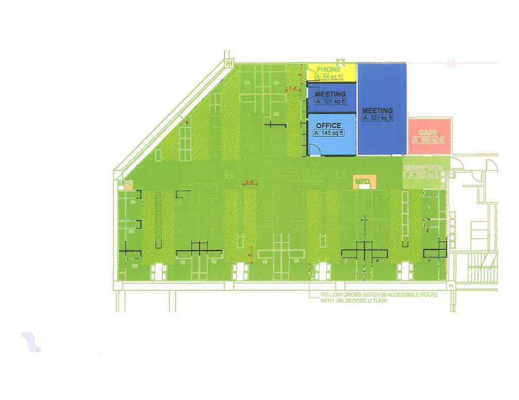
2 Item No.7: Add the following to Proposed Statement of Services; Article B4 Supplemental Provisions: B4.5 Space Planning- The Contracting Agency will provide a conceptual space plan design plan depicting what the Contracting Agency wants to see regarding their recent adoption of the Universal Space Planning Standards, to help facilitate the Contractors requirements under Sec. B2.0.4 Space Planning. Attached as Attachment No.3 is a diagram of a recent space plan converting the space to the new Universal Space Standards. The plan is for reference purposes only to illustrate the conceptual level of space planning drawings currently being completed by the Contracting Agency s space planner. ItemNo.8: Add the following to the Project Narrative as an additional item to the scope of work will be Protection Against Flood Damage To mitigate and/or reduce future flooding and or deterioration to the building from floods review Nome Ordinances and NCO (c)(2)(B). The Nome State Office Building can be flood-proofed as contemplated by NCO (c)(2)(B). Flood proofing two of the three feet would be required under the ordinance and is included in the renovation HMS cost estimate, the cost to extend this flood-proofing a final third foot would be inconsequential. Potential Scope would be as follows: Move all critical mechanical and electrical equipment from crawlspace to roof top, this includes air-handlers and ductwork. This avoids future damage as well as mitigates against air quality issues resulting from water related issues such as mold. Provide sump pump in crawlspace to mitigate potential leakage. Leveraging mechanical means to augment natural drainage. Waterproof existing foundation and walls to 3 above existing first floor. This includes heavy duty door seals and thresholds to slow water infiltration. Waterproof coat existing steel columns that are in close proximity to grade. This is in conjunction with repairs to corrosion issues. Upgrade existing framed walls facing the sea and portions of end walls with concrete walls to mitigate storm debris impact damage. Add metal storm shutters at first floor windows for use during storms. Attached as Attachment No.4, for your reference, is Nome City Ordinance Chapter Flood Plain Regulations. NOTED ATTACHMENTS FOLLOW END OF ADDENDUM No. 5 By: Dan Reynolds Dan Reynolds, Facilities Contracting Officer Total number of pages contained within this Addendum: 19 RFP# ADDENDUM # 5 Request for Proposal Page 2 of 2


3
4 VOICE AND DATA REQUIREMENTS, Telecommunications Distribution System (TDS) PART 1, GENERAL DESCRIPTION AND GENERAL SPECIFICATIONS A. The intent of this Specification is to place in working order a complete, fully tested and documented Telecommunication Distribution System consisting of wall or free standing equipment racks or cabinets, telecom rooms (where applicable), a Category 5e horizontal cable sub-system, cable pathways, and an optical fiber cable backbone subsystem (where applicable) complying with the Codes and Standards referenced herein. The TDS shall include (but not be limited to) provision of all raceways, sleeves, boxes, gutters, shelves, enclosures, shelf and enclosure supports, backboards, equipment racks, line and low voltage wire and cable, patch cords, pull ropes (in unused conduits), terminal modules, panels, outlets, jacks, splices, connections, cable management, labeling, testing and all other material, equipment, and labor required to make the systems fully operational. B. Local access to Fiber Optic Metropolitan Area Networks: For any site to be considered, the offered space shall have direct connectivity to the carrier s fiber connected network at the facilities point of demarcation. The Offeror must include any cost that may be associated with this requirement in the price offer section (6.2) of the RFP. COORDINATION A. The layout and installation of the systems specified herein shall be coordinated such that all special requirements for telecommunications systems shall be provided and incorporated into the project. The systems to be coordinated shall include (but are not limited to) electrical raceway, optical fiber backbones (where applicable) grounding, fire rated assembly, lighting, power distribution, control and instrumentation, and labeling of cables, terminations, outlets, jacks, etc. CODES AND STANDARDS A. Where a Nationally Recognized Testing Laboratory (NRTL) listing or classification exists for a product and the product is suitable for the purpose specified and indicated, the product shall bear the appropriate marking indicating the listing or classification. B. Where a UL Standard is in effect, equipment shall: 1. Meet that Standard. 2. Bear the UL Label. REFERENCE CODES AND STANDARDS A. The publications listed below form a part of this specification to the extent referenced. The publications are referred to in the text by basic designation only, latest edition. The reference codes and standards are minimum requirements. Reference ANSI/IEEE C2 ANSI/NFPA 70 Title/Revision National Electrical Safety Code National Electrical Code ANSI/TIA/EIA-568-B.1 Commercial Building Telecommunication Cabling Standard Part 1: General Requirements ANSI/TIA/EIA-568-B.2 Commercial Building Telecommunication Cabling Standard Part 2: Balanced Twisted-Pair Cabling Standards ANSI/TIA/EIA-568-B.2-1 Commercial Building Telecommunication Cabling Standard Part 2: Addendum 1: Transmission Performance Specifications for 4-Pair 100Ohm category 6 cabling, 2002 ANSI/TIA-568-B ANSI/TIA/EIA-569-A ANSI/TIA/EIA-606-A Transmission Performance Specifications for 4-Pair 100 Ohm Augmented Category 6 Cabling Commercial Building Standards for Telecommunications Pathways and Spaces Administration Standard for Commercial Telecommunications Infrastructure VOICE AND DATA REQUIREMENTS, Telecommunications Distribution System (TDS) Page 1 of 11
5 Reference ANSI/TIA/EIA-607 BICSI Title/Revision Commercial Building Grounding and Bonding Requirements for Telecommunications Telecommunications Distribution Methods Manual IEEE LAN Standards: 802.3; 802.4; 802.5; UL 1449 Transient Voltage Surge Protection OPERATING CONDITIONS A. Telecom Rooms shall support electronic equipment designed for office environments and shall maintain continuous operation of such equipment under ambient environment conditions of between 64 degrees F and 75 degrees F. Relative humidity shall be maintained between 30% and 55%, non-condensing. Cooling and humidification/de-humidification to maintain such an environment shall be provided in each Telecom Room. Cooling and humidification/de-humidification to maintain such an environment shall be provided in each Telecom Room, all cooling and humidification/de-humidification equipment required for this room shall not be installed directly above the equipment rack. QUALITY ASSURANCE A. Perform all Work in accordance with all regulatory rules and regulations as well as references in this specification. B. Perform all Testing in accordance with ANSI/TIA/EIA-568-B specifications. QUALIFICATIONS A. The telecommunications work specified in this Section is acknowledged to require special skills mastered by education, experience, or both. In an effort to provide a minimum level of quality in products and installation, telecommunications work described in this Section shall be performed by specialty telecommunications contractors. B. Installation Certification: 1. The installation shall be performed by a certified installer of the cabling system, pre-qualified by the Manufacturer for the purpose of offering the Extended System Warranty as required in this Section. C. Contractor Experience: 1. Specialty subcontractors performing telecommunications work shall have a minimum of three years experience in the construction, testing, and servicing of systems of the type and magnitude specified herein. REGULATORY REQUIREMENTS A. Work shall conform to the requirements of NFPA 70 and all local amendments. B. Work shall conform to the requirements of all Federal, State and Local Electrical and Telecommunications Regulations. Extended WARRANTY A. To provide a minimum level of quality in products and installations, the Telecommunication Distribution System shall be provided with a manufacturer backed warranty that shall extend from the date of Project Completion to the longer of twenty (20) years or the length of the Extended Warranty offered by the manufacturer of the system. B. The Extended Warranty shall be extended to the Lessor via the manufacturer through a single point of contact and shall be fully backed by the manufacturer. The Extended Product Warranty and System Assurance Warranty for the Telecommunication Distribution System shall consist of the following: 1. Extended Product Warranty - The Extended Product Warranty shall ensure against product defects, that all approved cabling components exceed the specifications of ANSI/TIA/EIA 568-B and ISO/IEC IS B, exceed the attenuation and NEXT requirements of ISO/IEC IS B for cabling links/channels, and that the installation will exceed the loss and bandwidth requirements of ISO/IEC IS B for links/channels. The warranty shall apply to all passive Telecommunication Distribution System (TDS) components. 2. System Assurance - The System Assurance shall cover the failure of the wiring system to support any existing application, as well as additional application(s) introduced in the future by recognized standards or user forums that use the ANSI/TIA/EIA 568-B or ISO/IEC IS B component and link/channel specifications for cabling. 3. All communications system components shall be rated for end-to-end system Category 5e or greater performance levels on all pair combinations and warranted to support any existing or future applications which are designed to operate over a VOICE AND DATA REQUIREMENTS, Telecommunications Distribution System (TDS) Page 2 of 11
6 100 MHz horizontal channel (as defined in ANSI/TIA/EIA 568-B.2.1). Performance shall be guaranteed under the Extended Warranty at 100 meters (328 feet): C. Warranty programs approved as meeting the specified warranty are listed below. 1. Commscope Systimax Program. 2. Panduit Pan-Net Performance Guarantee 3. Siemon Cabling System Premium 5e Warranty. 4. ADC TrueNet Warranty Program. 5. Ortronics Applications Assurance and Extended Warranty Program MANUFACTURERS' RECOMMENDATIONS A. Installation procedures shall be in accordance with the recommendations of the manufacturer of the material being installed. A copy of the recommendations shall be kept at the job site. TERMINOLOGY A. TDS shall refer to the Telecommunication Distribution System cabling and hardware infrastructure internal and external to a building or buildings used to transmit voice, video and data, etc. B. "Stations" shall refer to individual telephone or computers, or remote peripherals of those systems (e.g., printers, facsimile machines, modems, etc. C. "Outlets" shall refer to the group of receptacles or jacks at the location where the stations connect. D. "Jacks" or "Ports" shall refer to the individual receptacles where phones, computers, etc. connect. E. "Station Cables" shall refer to the horizontal cables connecting patch panels or terminal blocks in the Telecommunications Rooms to the stations. F. Pathways shall refer to conduits, sleeves, cable-trays, distribution rings, etc., which are employed to route backbone and stations cables between equipment rooms, telecommunications rooms, stations, outlets, etc. G. Backbone Cables, "Riser Cables" or "Tie Cables" shall refer to copper cables 25-pair or more and optical fiber cables 2- strand or more, connecting main cross-connect facilities, intermediate cross-connect facilities and telecommunications rooms. These cables may include riser cables between floors. H. Equipment Rooms (ER) or "Communication Equipment Rooms" (CER) shall refer to a special-purpose room that provides space and maintains a suitable operating environment for large communications and/or computer equipment. Main rooms may also be referred to as an MDF. I. Telecommunications Rooms (TR)" shall refer to a floor-serving facility for housing telecommunications equipment, cable terminations and cross-connect wiring. This is the point at which station cables terminate. It may also be referred to as an IDF. J. "Terminal Blocks" shall refer to multiple punch down cable terminations. K. Patch Panels shall refer to rack or frame mounted multiple punch down cable terminations with RJ-45 style, 8P8C jacks on the face for plug and play cross connect capability. L. Cable Management shall refer to rings, troughs, gutters etc., mounted in conjunction with telecommunications distribution equipment and terminal blocks, for the orderly routing of cables, patch cords, etc. M. LEC shall refer to the Local Exchange Carrier providing telephone service to the facility. TELECOM RACK, CABINET, and DEDICATED ROOMS A. Telecom cabinets, racks, single, and multiple telecom rooms shall be provided per the following: Size of Lease Space Cabinet/Rack/Telecom Room Configuration Wall mounted equipment cabinet with two dedicated 20A, 120V power circuits < 625 ft ft 2 1,000 ft 2 1,001 ft 2-3,000 ft 2 3,001 ft 2-8,000 ft 2 > 8,000 ft 2 Provide one wall mounted cabinet per Part 2 N/A N/A N/A N/A VOICE AND DATA REQUIREMENTS, Telecommunications Distribution System (TDS) Page 3 of 11
7 Cabinet/Rack/Telecom Room Configuration Wall mounted equipment cabinet with three dedicated 20A, 120V power circuits Single Telecom Room (8 x 10 minimum) with a free standing equipment rack and six dedicated 20A, 120V power circuits Single Telecom Room (9 x 11 minimum) with a free standing equipment rack and six dedicated 20A, 120V power circuits Multiple Telecom Rooms (each 9 x 11 minimum) each with a free standing equipment rack and six dedicated 20A, 120V power circuits Notes 1. N/A Not Applicable Size of Lease Space < 625 ft ft 2 1,000 ft 2 1,001 ft 2-3,000 ft 2 3,001 ft 2-8,000 ft 2 > 8,000 ft 2 N/A Provide one wall mounted cabinet per Part 2 N/A N/A Provide one free standing rack per Part 2 N/A N/A N/A N/A N/ N/A N/A N/A Provide one free standing rack per Part 2 N/A N/A N/A N/A Provide one telecom room for each 8,000 ft 2 each with one free standing rack per Part 2 2. For multiple telecom rooms, provide a 12 strand singlemode backbone fiber optic cable between a main telecom room and each additional telecom room. 3. For multiple telecom rooms, provide a 25 pair backbone riser cable between a main telecom room and each additional telecom room. 4. Where Telecom Rooms are shared, provide equipment cabinets in lieu of racks. PART 2, PRODUCTS GENERAL A. Some specific requirements in Part 2 of this Specification may not be applicable to all Leases. Refer to Part 1 of this Specification to determine specific requirements based upon size of lease space. B. Materials shall be as specified, first quality, manufacturer s current production. C. Copper cabling, connecting hardware, and related hardware shall be Commscope hardware with Commscope cable as required under the Commscope Systimax Warranty to establish standards for quality and performance. Listed manufacturers meeting all the system quality, performance and warranty requirements of this specification are also acceptable. Any other manufacturer s products must be approved by the State. 1. Approved alternate connecting hardware products manufacturers are: a. Panduit b. ADC c. Siemon d. Ortronics 2. Approved alternate cabling products manufacturers are: a. Panduit b. ADC VOICE AND DATA REQUIREMENTS, Telecommunications Distribution System (TDS) Page 4 of 11 N/A
8 c. Belden D. Fiber optic cabling, connecting hardware, and related hardware in this section shall be Commscope hardware with Commscope cable as required under the Commscope Systimax Warranty to establish standards for quality and performance. Listed manufacturers meeting all the system quality, performance and warranty requirements of this specification are also acceptable. Any other manufacture s products must be approved by the State. 1. Approved alternate connecting hardware products manufacturers are: a. Corning Cable Systems 2. Approved alternate cabling products manufacturers are: a. Corning Cable Systems E. Products shall provide the standard of performance required under paragraph 1.1 and the Special Warranty above. TELECOM ROOMS A. Telecom Rooms shall be placed in a location that provides secure access from a common area and that minimizes the lengths of horizontal cabling so as not to exceed 90 meters in accordance with applicable Standards. Telecom Room doors shall swing outwards except where prohibited by Code and be key lockable. Telecom Room sizes and power requirements shall be based upon the size of the Lease Space as outlined in Part 1 of these Specifications: B. Termination Backboards shall be provided in Telecom Rooms consisting of the following: 1. Material: Type AC fire retardant plywood. Mount the plywood with the A side exposed. 2. Size: 3/4 inch to cover all walls. 3. Finish: Flat latex, intumescent fire retardant paint, Flame Control Coatings No , or equal. Paint plywood on all sides and edges including the back of the termination board prior to mounting on walls. C. Flooring in Telecom Rooms shall consist of the following: 1. For new buildings an anti-static tile floor shall be provided. For remodels when the floor is bare slab, paint it with antistatic paint and seal with anti-static sealant to hold down dust. 2. Material: Static Dissipative, Vinyl Composition Tile equal to Armstrong SDT. 3. Provide grounding connection to each static dissipative flooring system in two locations, in accordance with manufacturer s instructions. SEISMIC BRACING A. Freestanding equipment racks shall be seismically braced in accordance with requirements of the IBC. Seismic bracing shall consist of rigid supports. Cables, wires, chains or other non-rigid materials shall not be used for seismic support. Provide approved fixed equipment anchorage assemblies as published by the manufacturer. FREE-STANDING EQUIPMENT RACKS A. Where required by these Specifications, provide full height 19-inch wide NEMA standard open rack frame with the following features. 1. Vertical cable management channels with front mounted cable management rings and top mounted cable trough. 2. Releasable hook and loop cable support straps. 3. Rack assembly shall fit within 24 inches wide by 16.5 inches floor area. 4. Material and Finish: Steel with black powder-coat painted finish. 5. Electrically isolated inch by 1 inch by 60 inches chassis ground bus bar on the right rear side of the rack, bonded to the chassis with #6 braided by 6 inches long bonding jumpers. WALL MOUNTED EQUIPMENT CABINETS A. Where required by these Specifications, provide 19 inch wide,14 inch deep NEMA standard open-frame, fixed, wall mounted equipment rack with the following features: Rack Unit (RU - 1 3/4 inch) mounting spaces. 2. Laser cut steel, with black anodized finish. 3. Vertical mounted cable management brackets for vertical cables VOICE AND DATA REQUIREMENTS, Telecommunications Distribution System (TDS) Page 5 of 11
9 4. Material and Finish: Steel with black powder-coat painted finish. 5. Electrically isolated 3/16 inch by 3/4 inch by 18-5/16 inches ground busbar on the top rear side of the rack. Mount ground busbar on 1 inch insulating bushed standoffs. 6. Lockable front door. FREE-STANDING EQUIPMENT CABINETS A. Where required by these Specifications, provide full height 19 inch wide 30 inch deep NEMA standard enclosures with the following features: 1. Interior vertical cable management channels with front mounted cable management rings. 2. Releasable hook and loop cable support straps. 3. Top, bottom, front, rear, and side panels. 4. Top panel shall have provisions for two openings for optional 4 inch standard fans. 5. Top mounted 4-inch cooling fans. 6. Rack assembly shall fit within 24 inches by 36 inches floor area. 7. Material and Finish: Steel with black powder-coat painted finish. 8. Electrically isolated inch by 1 inch by 60 inches chassis ground bus bar on the right rear side of the rack, bonded to the chassis with #6 braided by 6 inches long bonding jumpers. 9. Lockable front and rear doors. CABLE MANAGEMENT A. In Telecom Rooms, provide backboard mounted cable management to arrange cables and wires in a neat and workmanlike manner. 1. Distribution rings installed in telecom rooms shall be D ring type. No bridle rings are permitted. 2. Distribution rings shall be sized according the number and size of cables to be supported plus 25% spare capacity. B. In wall and floor mounted, equipment racks and cabinets, provide rack mounted cable management to arrange cables in a neat and workmanlike manner. Provide vertical and horizontal rack mounted cable management per the following: 1. Vertical trough-type cable management for use with standard 7 foot equipment rack shall be minimum 4 inches deep. 2. Horizontal trough-type cable management shall be 3-1/2 inch wide with horizontal and vertical routing rings, with 2 inches by 1.5 inch cutouts for through cable routing. IDC TERMINAL MODULES A. Hardware shall be rated for ANSI/TIA/EIA 568-B Category 5e ratings and installed in accordance with ANSI/TIA/EIA 568-B guidelines. Blocks shall be color coded and documented in accordance with ANSI/TIA/EIA 606-A. Blocks shall be identified using clear label holders and labels. Blocks shall be UL Listed. B. Terminal Modules shall be of the Insulation Displacement (IDC) and shall support the system Category of the permanent channel hardware installed. C. Where required, building entrance protection terminals shall be provided by the LEC. HORIZONTAL CABLE PATCH PANELS A. Patch Panels: Modular jack panels shall be provided in either 24 (1 Rack Unit) or 48 (2 Rack Units) port configurations. Modular jack panel installations shall contain a retaining trough between every panel. Modular Jack Panels shall be wired for T568A configuration. Patch panels shall have the following characteristics: 1. The terminations shall meet or exceed performance defined by ANSI/TIA/EIA-568-B.2, for Category 5e component, link, and channel performance. 2. UL Listed. 3. Comply with FCC Part Manufactured by an ISO 9001 Certified Manufacturer. VOICE AND DATA REQUIREMENTS, Telecommunications Distribution System (TDS) Page 6 of 11
10 HORIZONTAL CABLE INFORMATION OUTLETS/JACKS A. Outlet Requirements: 1. Single gang outlet information outlets shall be arranged in a quad-plex jack arrangement. 2. Provide outlet faceplates with both top and bottom labeling positions. 3. Provided blank module inserts for all unused module locations. 4. Provide full set of color coded snap-in icons for workstation outlets for use by the Lessor to mark jacks for analog and digital telephones, two unique classes of data, etc. Store icons in clear plastic bags in each IDF/MDF. B. Communication Jack Requirements: Communications jacks shall consist of multi-position 8-pin modular (8P8C) jacks, utilizing the T568A termination style. Jacks shall have the following characteristics: 1. Jacks shall be manufactured by the same manufacturer as the modular patch panels. 2. The jacks shall meet or exceed performance defined by ANSI/TIA/EIA-568-B.2, for Category 5e component, link, and channel performance. 3. UL Listed 4. Comply with FCC Part Manufactured by an ISO 9001 Certified Manufacturer. HORIZONTAL CABLE PATCH CORDS A. Provide factory assembled Category 5e Modular Patch Cords for each assigned port on the patch panel. Cords shall conform to the requirements of ANSI/TIA/EIA 568-B Commercial Building Telecommunications Cabling Standard, Horizontal Cabling Section, and be part of the UL LAN Certification and Follow-up Program. Cords shall be equipped with an 8 pin modular connector on each end and the minimum length patch cord shall be provided in each instance, to make an orderly, manageable connection between the patch panels or equipment being cross-connected. B. Patch cords shall be round, and consist of 24-AWG copper, stranded conductors, tightly twisted into individual pairs. C. Patch cords shall be manufactured by the manufacturer of the patch panels and jacks and meet or exceed the Channel performance defined by ANSI/TIA/EIA-568-B. HORIZONTAL CABLES A. General: 1. Horizontal cables shall be rated for Category 5e performance and shall be extended between the station location and its associated TR and shall consist of 4 pair, 24 gauge, UTP, and shall be terminated on the 8 pin modular jacks provided at each outlet. The 4 pair UTP cable shall be UL Listed Type CMP for use in plenum spaces in accordance with Article 800 of the NEC. 2. Provide cables with four FEP insulated conductor pairs (4/0 configuration). 3. Cables shall meet or exceed Category 5e performance specifications for the Channel as defined by ANSI/TIA/EIA-568- B UL or ETL Verified for Category 5e Electrical Performance. 5. UL Listed for Fire Safety. 6. Manufactured by an ISO 9001 Certified Manufacturer. SINGLE-MODE FIBER OPTIC CABLE A. Where back bone fiber optic cables are required due to multiple telecom rooms per Part 1 of this Specification, provide single-mode (SM) fiber optic cable between the telecom rooms. The single-mode fiber optic cable shall be 8.3 μm (typical) step-index optical glass with nominal 125 μm core/cladding diameter. The optical fiber shall comply with ANSI/TIA/EIA-492CAAA. Single-mode fiber for indoor applications shall be of the tight buffered design. B. Single-mode fiber shall meet the following specifications: 1. Maximum Attenuation: 1.0/ /1550 nm. 2. Maximum Distance for Running 1 GbE: nm. C. Fibers shall be color coded to facilitate individual fiber identification. Fibers shall have protective coating to ensure color retention, minimize micro-bending losses and improve handling. The coating shall be mechanically strippable. VOICE AND DATA REQUIREMENTS, Telecommunications Distribution System (TDS) Page 7 of 11
11 FIBER OPTIC CABLE PATCH CORDS A. Where back bone fiber optic cables are required due to multiple telecom rooms per Part 1 of this Specification, provide fiber optic cable patch cords from same manufacturer as that providing fiber optic cabling. These fibers shall be constructed from glass of the same grade as that used to construct the backbone and horizontal cables. B. Single-mode Patch Cord Specifications: 1. The fiber patch cord shall consist of buffered, step-index fiber with an 8.3 micron core (typical) and a 125 micron cladding. The fiber coating shall be covered by Aramid yarn and a flame retardant jacket. 2. Provide two-strand riser rated zipcord style cords for all duplex patch through and equipment connection applications. Provide single strand cords for single equipment connections. 3. Provide patch cords factory terminated with connectors in the type specified herein in the quantity and length(s) required to make an orderly, manageable connection between all patch panels and equipment being crossconnected. FIBER OPTIC CABLE PATCH PANELS A. Provide low density termination and administration points (patch panels) for the fiber cables in the telecommunications rooms where backbone fiber optic cable is required due to multiple telecom rooms per Part 1 of this Specification. The termination and administration points (patch panel) shall meet the following requirements: 1. Stackable and able to fit within a 19-inch rack frame with six adapter panel positions per two unit (3.5 inch) frame. 2. Hinged translucent door on the front side of the connector panels 3. Factory installed lock kit for hinged front panel furnished with two keys for each front panel. 4. Room and provisions to provide fiber identification. 5. Pre-punched and pre-loaded adapter panels with fiber adaptors of the types specified herein, recessed a minimum of 2.5 inches from the front of the shelf for patch cable management. 6. Fully front and rear accessible. The unit shall slide out to allow top access. 7. Protection features for the connectorized fiber to prevent mechanical stress, macro-bending losses at the connection point, and tampering with the circuits. 8. Protection for fiber patching or splicing. 9. Jumper routing bend limiters. FIBER OPTIC CABLE CONNECTORS A. Provide field installable single-mode (SM) connectors to terminate fiber optic cables from cable-to-cable, cable-toequipment or equipment-to-equipment, and to make jumpers where backbone fiber optic cable is required due to multiple telecom rooms per Part 1 of this Specification. B. The connectors shall be capable of mounting on either 0.9 mm buffered fiber or on 3.0 mm cordage and utilize a PC polishing on the tip to provide high yield during installation. All connectors shall have ceramic ferrules, meet EIA and IEC standards for repeatability and have a locking feature to the coupler and assure non-optical disconnect. C. Provide type LC connectors, unless otherwise noted. These connectors shall meet the following criteria: 1. LC Connector Specifications: a. Typical Insertion Loss: 0.10 Db. b. Return Loss: better than -26 db MM, -55 db SM. c. Temp. Stability: -40ºC to 75ºC BACKBONE RISER CABLES A. Unshielded multi-pair copper cables shall be used as the vertical riser cables where required due to multiple telecom rooms per Part 1 of this Specification. The cable shall support voice, data and building service applications. The bending radius and pulling strength requirements of all backbone cables shall be observed during handling and installation. The multi-pair copper cables shall be in non-plenum form and placed in conduit as required. B. The non-shielded non-plenum cable shall consist of 24-AWG solid-copper conductors insulated with color coded PVC. The cable shall be available in 25, 50, 75 and 100 pair as required. The multi-pair cable shall be UL Verified to ANSI/TIA/EIA 568-B for Category 3 performance levels and have the following characteristics: VOICE AND DATA REQUIREMENTS, Telecommunications Distribution System (TDS) Page 8 of 11
12 1. UL Listed for Fire Safety. 2. Manufactured by an ISO 9001 Certified Manufacturer. LABELING A. Provide machine printed labels for all patch panels, cables, outlets, etc., in accordance with ANSI/TIA/EIA-606-A. B. Labeling and color coding identification shall conform to TIA/EIA-606-A for a Class 1 Administrative System where only a wall mounted Equipment Cabinet or a single Telecom Room is required (due to size of the Lease Space per Part 1).. C. Labeling and color coding identification shall conform to TIA/EIA-606-A for a Class 2 Administrative System where a Main Telecom Room and additional Telecom Room(s) are required (due to size of the Lease Space per Part 1). UNSPECIFIED EQUIPMENT AND MATERIAL A. Any item of equipment or material not specifically addressed in this document and required to provide a complete and functional TDS installation shall be provided in a level of quality consistent with other specified items. PART 3 EXECUTION GENERAL A. Wiring shall be neatly tied or laced in cabinets and terminated on terminal strips provided for the purpose. B. Outlet/Jacks shall be identified with machine printed labels. Hand lettered labels shall not be used. C. Labels and color-coded inserts for each jack at patch panels and wall outlet shall be in accordance with TIA/EIA-606-A. D. Installation of lighting, ventilation and all other systems in the telecom rooms shall be coordinated with other trades and systems to avoid interferences. E. In each TR, IC, MDF, IDF and equipment room a minimum 22 inches by 34 inch CAD drawing indicating an appropriate floor plan and a telecommunication one-line (where applicable) shall be provided. The floor plan shall indicate telecommunication outlets with the appropriate outlet designation indicated on the plan. Mount drawing beneath a sheet of 1/8 inch clear Plexiglas on wall. Provide marking pens attached with Velcro to facilitate marking when moves, adds, or changes occur. Plexiglass and floor plan shall be mounted in such a way as to allow easy and rapid updates to the underlying floor plan. Include all copper and optical fiber systems (where applicable) on this drawing. CODES AND PERMITS A. Work shall be performed with the necessary permits, etc. and by obtaining serving utility and governmental approvals where required. B. Coordinate work with the serving utility. C. Raceway fill requirements for communications systems shall be in accordance with ANSI/TIA/EIA-569-A and BICSI. D. NEC bending radius of all communications ducts, raceways, cabletrays, etc., shall be not less than the installed cable manufacturer's recommendations, and the applicable ANSI and BICSI Standards. E. Communications work shall be in complete accordance with the following: 1. National Electrical Code (NEC), latest legally enacted edition. 2. Regulations of the State Fire Marshall. 3. National Fire Protection Association (NFPA) Codes. 4. State, county and local codes and ordinances. LAYOUT A. Maximum height for terminal blocks and patch panels shall be 6 feet-6 inches, minimum height shall be 1 feet-6 inches. Cables shall be racked and supported in a workmanlike fashion. Work shall be labeled according to ANSI/TIA/EIA 606-A, and color coded according to BICSI Standards. The following guidelines shall apply governing the layout of terminations. 1. Horizontal cables from a common outlet shall terminate sequentially (in groups) on the same patch panel. 2. Pairs from each cable shall be terminated sequentially from left to right, top to bottom starting with the lowest assigned number at the upper left hand corner of the frame. VOICE AND DATA REQUIREMENTS, Telecommunications Distribution System (TDS) Page 9 of 11
13 3. Trunk or riser cables shall terminate on dedicated terminal blocks, separate from but adjacent to horizontal terminal blocks. Cross-connect or patch cords longer than 18 feet shall be avoided. Install stress relief hardware where needed. B. Up to date "As-built" record drawings detailing the layout of all equipment racks and cabinets, telephone, data and trunk terminations, including a typed listing of cables/rooms served by each terminal block and patch panel shall be provided to the Lessor by the installer. CABLE INSTALLATION A. Cable pathways and supports shall be sized for 40% fill ratios. B. Follow cable manufacturer s specification regarding handling methods, retaining/support methods, bending radius and maximum pulling tension limitations. C. Telecommunication cables shall not be installed in the same raceway as power cables. D. Cables shall be installed in a neat and orderly manner and shall not cross or interlace other cables except at breakout points. E. Cables in vertical trays shall be individually retained with straps at a maximum of 6 feet on center. F. Tie wraps shall not deform the cable insulation when tightened. G. Cables shall be routed to minimize EMI and RFI interference. Cable shall be routed according to the following table. Spacings are minimum for all Category 3 and higher cable. Minimum Separation Of Telecommunications Pathways From 480 Volt Or Less Power Lines Condition <2 kva 2-5 kva >5 kva Unshielded power lines or electrical equipment in proximity to telecommunications open or nonmetal pathways. Unshielded power lines or electrical equipment in proximity to telecommunications grounded metal conduit pathways Power lines enclosed in a grounded metal conduit (or equivalent shielding) in proximity to a telecommunications grounded metal conduit pathway Power lines enclosed in a grounded metal conduit (or equivalent shielding) in proximity to telecommunications open or nonmetal pathways. Mechanical ductwork, metal floors and other metallic planes to telecommunications open or nonmetal pathways. Mechanical ductwork, metal floors and other metallic planes to telecommunications open or grounded metal conduit pathways. 5 in 12 in 24 in 2.5 in 6 in 12 in N/A 3 in 6 in 2.5 in 6 in 12 in Fluorescent or HID lighting fixtures 5 in 5 in 5 in 2 in 0 in DISTRIBUTION RINGS AND CABLE SUPPORTS A. J-hooks shall be mounted on appropriate mounting hardware suitable for the specific application. Mount securely to the building structure. Maximum support spacing shall be 4 feet on center. B. The layout of cableways and pathways shall be coordinated with other trades. CROSS-CONNECTIONS A. Cross-Connections at and/or between all terminal hardware shall be provided to form a complete and functioning system. B. Patch Cords shall be used to make all Cross-Connections. VOICE AND DATA REQUIREMENTS, Telecommunications Distribution System (TDS) Page 10 of 11
14 INTERCONNECTIONS A. Interconnections at terminal hardware shall be provided to form a complete and functioning system. EQUIPMENT RACKS A. Equipment racks shall be seismically braced by securely bolting to the structural floor supplemented with additional braces as required for the Seismic Zone. 1. Mount ground bars on insulating bushed standoffs. 2. Electrically separate open and enclosed racks with insulating washers and nonconductive screws. TERMINATIONS A. Wire twist shall be maintained to within 0.25 inch of the termination. COMPLETION AND TESTING A. Telecommunications System test reports shall be submitted to and approved by the Contracting Agency. The test reports shall certify that the Telecommunications Distribution System is complete, passes test criteria, is fully operational, and that all work has been witnessed as specified. B. Final Inspection Tests: 1. Link testing of all copper cabling shall be performed. Complete, end to end test results shall be submitted to the Contracting Agency. a. Category 5e cable runs shall be tested for conformance to the specifications of EIA/TIA 568-B.2, Category 5e. Testing shall be done with a ANSI/TIA/EIA 568-B ETL verified Level II-E test set. 1). Test shall include all requirements of ANSI/TIA/EIA 568-B. 2). Any cables not meeting the requirements of the standard shall be brought into compliance at no additional charge. 2. Where backbone fiber optic cable is required due to multiple telecom rooms per Part 1 of this Specification, Perform inplace testing of all installed, terminated fibers in accordance with TIA/EIA OFSTP-7 methods. Document and submit all test results in accordance with the Specifications. a. Single-mode Testing: 1). Perform optical power loss measurements in accordance with TIA/EIA Standard OFSTP-7 using method A.3. 2). Method A.3: Using an Optical Loss Test Set (OLTS) with hard-copy and disk/cd output capability to test each installed single-mode permanent link fiber from both directions at 1310 and 1550 nm. 3). Cables not meeting the requirements of the standard shall be brought into compliance at no additional charge. VOICE AND DATA REQUIREMENTS, Telecommunications Distribution System (TDS) Page 11 of 11


15
16 11/26/12 Print Prev iew Sections: Platting board Platting regulations Consultation Appeal. Chapter PLATTING AUTHORITY Platting board. The planning commission shall assume all jurisdiction and authority as the Nome platting board. (Ord. O (part), 1994) Platting regulations. The platting board shall recommend to the city council regulations for real estate subdividing within the city, including but not limited to regulations controlling all physical aspects of the subdivision, regulations controlling the form of plat documentation, and regulations establishing procedures for the approval, modification, correction or disapproval of plats submitted for filing. The planning commission shall publish notice of and hold at least one hearing on the proposed regulations before submitting its recommendations to the city council and the city council shall publish notice of and hold at least one hearing on the proposed regulations before enactment by resolution. The planning board may require by regulation the submission of a preliminary or sketch subdivision plat during the platting procedure. (Ord. O (part), 1994) Consultation. During the process of reviewing a proposed subdivision, the platting board shall consult with and obtain recommendations from the city manager and any administrative staff personnel possessing specialized expertise regarding the specific issue for decision. (Ord. O (part), 1994) Appeal. Any person aggrieved by a decision of the platting board regarding a proposed filing of a subdivision plat may appeal to the board of adjustment in accordance with the procedures set forth in Chapter NCO. (Ord. O , 2009: Ord. O (part), 1994) Sections: Chapter FLOODPLAIN REGULATIONS Statement of purpose Lands to which this chapter applies Basis for establishing the areas of special flood hazard Applications Floodplain coordinator. 1/15
17 11/26/12 Print Prev iew Protection against flood damage Standards for residential and nonresidential construction Implementation Disclaimer of liability Abrogation and greater restrictions Interpretation Definitions Variance procedures Statement of purpose. It is the purpose of this chapter to promote the public health, safety, and general welfare, and to attempt to minimize public and private losses due to flood conditions in specific areas, by provisions designed: (a) To protect human life and health; (b) To attempt to minimize expenditure of public money and costly flood control projects; (c) To attempt to minimize the need for rescue and relief efforts associated with flooding and generally undertaken at the expense of the general public; (d) To attempt to minimize prolonged business interruptions; (e) To attempt to minimize damage to public facilities and utilities such as water and gas mains, electric, telephone and sewer lines, streets, and bridges located in areas of special flood hazard; (f) To help maintain a stable tax base by providing for the sound use and development of areas of special flood hazard so as to minimize future flood blight areas; (g) To ensure that potential buyers are notified that property is in an area of special flood hazard; and (h) To ensure that those who occupy the areas of special flood hazard assume responsibility for their actions. (Ord. O A 2 (part), 2010) Lands to which this chapter applies. This chapter shall apply to all areas of special flood hazard. (Ord. O A 2 (part), 2010) Basis for establishing the areas of special flood hazard. A scientific and engineering report entitled The Flood Insurance Study for the City of Nome, Alaska, dated May 3, 2010, and any revisions thereto, with accompanying flood insurance rate maps (FIRMs), and any revisions thereto, are hereby adopted by reference as the official Flood Insurance Study for the city of Nome and as the basis for regulation of development under this chapter. The flood insurance study is on file at Nome City Hall. (Ord. O A 2 (part), 2010) Applications. (a) Application for a building, remodeling, or moving permit for each structure within flood hazard areas shall be accompanied by the required fee. The application for a building, 2/15
18 11/26/12 Print Prev iew remodeling or moving permit within flood hazard areas shall be made on a form furnished by and returned to the building official. (b) The information furnished in the application shall include, but is not limited to: (1) The name and address of the owner of the tract; (2) A legal description of the tract; (3) Statement of the following elevations: (A) The ground elevation after site preparation; (B) Projected first-floor elevation; (C) The basement floor elevation, if applicable; (D) Base flood elevation data if the application is for a proposed subdivision or other development of more than fifty lots or larger than five acres; (4) If the structure is located in a flood hazard area, information that demonstrates that the structure will be adequately protected against flood damage and that the structure or site preparation will not adversely affect flood elevations or velocities. The required protective measures are set forth in NCO Section (c) The information furnished in the application may include plans in duplicate drawn to scale showing the nature, location, dimensions, and elevations of the area in question; existing or proposed structures, fill, storage of materials, drainage facilities, and the location of the foregoing. If plans are included they shall contain the following information: (1) Elevation in relation to mean sea level of the lowest floor (including basement) of all structures; (2) Elevation in relation to mean sea level to which any structure has been floodproofed; (3) Certification by a registered professional engineer or architect that the floodproofing methods for any nonresidential structure meet the floodproofing criteria in NCO Section (d)(2); and (4) Description of the extent to which a watercourse will be altered or relocated as a result of proposed development. (Ord. O A 2 (part), 2010: Ord , 2001; Ord. O (part), 1994) Floodplain coordinator. (a) The city manager or her designee shall be the floodplain coordinator. The floodplain coordinator is authorized to administer and implement this chapter including granting or denying development permit applications. (b) Duties of the floodplain coordinator shall include, but not be limited to: (1) Review all development permits to determine that the permit requirements of this 3/15
19 chapter have been satisfied. (2) Review all development permits to determine that all necessary permits have been obtained from those federal, state, or local governmental agencies from which prior approval is required. (3) Review all development permits to determine if the proposed development is located in the floodway. If located in the floodway, determine if the encroachment provisions of NCO Section are met. (4) Review subdivision proposals and other development, including manufactured home parks or subdivisions, to determine whether such proposals will be reasonably safe from flooding. If a subdivision or other development proposal is in an area of shallow flooding, determine if: (A) Such proposals minimize flood damage. (B) Public utilities and facilities are proposed to be constructed so as to minimize flood damage. (C) Adequate drainage is provided. (5) Where elevation data is not available either through the flood insurance study, FIRM, or from another authoritative source, review applications for building permits to determine if the proposed construction will be reasonably safe from flooding. (6) Where BFE data are utilized in Zone A, obtain and maintain records of the lowest floor and floodproofing elevations for new and substantially improved construction. (7) When base flood elevation data has not been provided (A and V Zones) in accordance with NCO Section , Basis for establishing the areas of special flood hazard, obtain, review, and reasonably use any base flood elevation and floodway data available from a federal, state or other source, in order to administer NCO Section (8) Where base flood elevation data is provided through the flood insurance study, FIRM, or required as in this section, obtain and record the actual elevation (in relation to mean sea level) of the lowest floor (including basement) of all new or substantially improved structures, and record whether the structure contains a basement. (9) For all new or substantially improved floodproofed structures where base flood elevation data is provided through the flood insurance study, FIRM, or as required in this section: (A) Verify and record the actual elevation (in relation to mean sea level); (B) Maintain any required floodproofing certifications; (C) Maintain for public inspection all records pertaining to the administration of this chapter.
Communications Page 1 of 9
 Page 1 of 9 Last Update: April 23 rd, 2014 Introduction Design In the design of Telecommunications systems in Purdue facilities, the overall consideration should be to understand and treat telecom as a
PHYSICAL FACILITIES Consultant s Handbook Division 27 COMMUNICATIONS 0000 COMMUNICATIONS
 1 Introduction 1.1 In the design of Telecommunications systems in Purdue facilities, the overall consideration should be to understand and treat telecom as a utility. It should be assumed that all new
The University of Texas at Austin September 30, 2011
 SECTION 27 05 26 GROUNDING AND BONDING FOR COMMUNICATIONS PART 1 - GENERAL 1.1 SUMMARY A. This section governs the products and execution requirements relating to furnishing and installing grounding and
SECTION LOW-VOLTAGE ELECTRICAL POWER CONDUCTORS AND CABLES (24 Volt AC/DC or Less)
") SECTION 260523 LOW-VOLTAGE ELECTRICAL POWER CONDUCTORS AND CABLES (24 Volt AC/DC or Less) PART 1 - GENERAL 1.1 SUMMARY A. Related Documents: 1. Drawings and general provisions of the Subcontract apply
SECTION 260523 LOW-VOLTAGE ELECTRICAL POWER CONDUCTORS AND CABLES (24 Volt AC/DC or Less) PART 1 - GENERAL 1.1 SUMMARY A. Related Documents: 1. Drawings and general provisions of the Subcontract apply
Telecommunication Spaces
 Telecommunication Spaces October 19, 2016 Page 1 Revision History Telecommunication Spaces Standard Effective Date Email Version Contact Phone OIT-TS strevena@csustan.edu 1.0 Stan Trevena 209.667.3137
This product specification is written according to the Construction Specifications Institute MasterFormat, 2014 Update.
 Kaf-Tech Product Specification This product specification is written according to the Construction Specifications Institute MasterFormat, 2014 Update. SECTION 260519 METAL CLAD CABLE - MC-PLUS Neutral
SECTION (Master Template Final-05) ELECTRICAL BOXES. A. Provide boxes for electrical equipment and wiring devices as follows:
 ELECTRICAL BOXES. A. Provide boxes for electrical equipment and wiring devices as follows:") SECTION 16130 (Master Template Final-05) ELECTRICAL BOXES PART 1 GENERAL 1.01 SECTION INCLUDES A. Provide boxes for electrical equipment and wiring devices as follows: 1. Wall and ceiling outlet boxes.
SECTION 16130 (Master Template Final-05) ELECTRICAL BOXES PART 1 GENERAL 1.01 SECTION INCLUDES A. Provide boxes for electrical equipment and wiring devices as follows: 1. Wall and ceiling outlet boxes.
BUSWAY LOW VOLTAGE (POW-R-WAY III) SECTION SECTION 16466
 SECTION SECTION 16466") BUSWAY LOW VOLTAGE (POW-R-WAY III) PART 1 GENERAL 1.01 1.02 SCOPE The Contractor shall furnish and install the busway system including all necessary fittings, hangers and accessories as specified herein
BUSWAY LOW VOLTAGE (POW-R-WAY III) PART 1 GENERAL 1.01 1.02 SCOPE The Contractor shall furnish and install the busway system including all necessary fittings, hangers and accessories as specified herein
NORTHWESTERN UNIVERSITY PROJECT NAME JOB # ISSUED: 03/29/2017
 SECTION 26 0526 - GROUNDING AND BONDING FOR ELECTRICAL SYSTEMS PART 1 - GENERAL 1.1 RELATED DOCUMENTS A. Drawings and general provisions of the Contract, including General and Supplementary Conditions
Addendum 1.0. For Lagrange Library Specification 1.0. Technology Consultants Fort Wayne, Indiana
 Addendum 1.0 For Lagrange Library Specification 1.0 Technology Consultants Fort Wayne, Indiana TECHNICAL SPECIFICATIONS FOR TELECOMMUNICATION DISTRIBUTION FACILITIES AND INSTALLATION PROCEDURES For Lagrange
UNDERGROUND SERVICES SECONDARY
 Reference UNDERGROUND SERVICES SECONDARY Underground services secondary... U- 1 General requirements for underground service... U- 2 Name of parts for underground service... U- 3 Conduit layouts... U-
A. Product Data shall be provided for each type of product indicated.
 32 31 13 CHAIN LINK FENCES AND GATES SECTION 1 GENERAL 1.1 SUMMARY This Section includes the following: 1. Chain Link Fences 2. Gates for Chain Link Fences. See electrical specifications for electrical
CONSOLIDATED EDISON COMPANY OF NEW YORK, INC Van Dam Street Long Island City, NY ELECTRIC METER SHOP DEPARTMENT
 CONSOLIDATED EDISON COMPANY OF NEW YORK, INC. 48-05 Van Dam Street Long Island City, NY 11101 ELECTRIC METER SHOP DEPARTMENT METER ENGINEERING SPECIFICATION MES-350 REVISION 3 June 2016 EFFECTIVE DATE
Specification Lightning Protection Systems
 Specification Lightning Protection Systems General: Summary A) This Section specifies the lightning protection system for the building(s) or structure(s). This system provides safety for the building and
PCC Structured Cabling Standards
 PCC Structured Cabling Standards VERSION 2.0 07DEC16 Presented by: Portland Community College Information Technology Infrastructure Services Page 1 of 67 PCC Structured Cabling Standards 5 Purpose 5 CONTRACTOR
THOMAS JEFFERSON UNIVERSITY HOSPITAL STANDARD OPERATING PROCEDURE FOR THE BUILD OUT OF TELECOMMUNICATIONS ROOMS AND ASSOCIATED SPACES
 THOMAS JEFFERSON UNIVERSITY HOSPITAL STANDARD OPERATING PROCEDURE FOR THE BUILD OUT OF TELECOMMUNICATIONS ROOMS AND ASSOCIATED SPACES PREPARED BYBALA CONSULTING ENGINEERS, INC FOR THOMAS JEFFERSON UNIVERSITY
OKLAHOMA STATE UNIVERSITY - BUILDING DESIGN STANDARDS
 Page 1 PART 1 - GENERAL 1.01 Intent of Document The information included in this section is intended to identify the SPECIFIC ITEMS required by Oklahoma State University (OSU) in the design and construction
SECTION GROUNDING AND BONDING
 SECTION 16060 PART 1 GENERAL 1.01 DESCRIPTION A. Section includes requirements for an electrical grounding system, including electrodes, grounding rods, connectors, insulators, equipment grounding and
City and County of San Francisco CONTRACT No A SFO - Data Center, Building 60 SECTION CABLE TRAYS FOR COMMUNICATIONS SYSTEMS
 SECTION 27 05 36 CABLE TRAYS FOR COMMUNICATIONS SYSTEMS PART 1 - GENERAL 1.1 SCOPE OF WORK A. Cable Trays for Communications Cabling 1. Cable Trays 2. Cable Runways 3. Basket Tray B. Cable Tray Support
SECTION HANGERS AND SUPPORTS FOR ELECTRICAL SYSTEMS
 SECTION 26 05 29 HANGERS AND SUPPORTS FOR ELECTRICAL SYSTEMS PART 1 GENERAL 1.1 DESCRIPTION A. Scope: 1. CONTRACTOR shall provide all labor, materials, equipment, and incidentals as shown, specified, and
UNIVERSITY OF CHICAGO
 UNIVERSITY OF CHICAGO Information Technology Services - ITS TELECOMMUNICATIONS STRUCTURED CABLING GUIDELINES AND SPECIFICATIONS INFRASTRUCTURE SERVICES May 2015 1 Contents 1 Introduction... 4 2.0 Planning
2008 NEC Guide Lines for Home Owner Doing Electrical Work on their Property
 2008 NEC Guide Lines for Home Owner Doing Electrical Work on their Property A brief summary of the most used code references for residential wiring State of Idaho Division of Building Safety Electrical
Electric Service Standards
 V: 1 of 6 A. Padmounted Requirements Complete requirements are contained in FPL specifications given to Customers for individual projects. Typical pad mounted transformer requirements include, but are
Shur-Shot X-Proof Hydrogen Fluoride Alarm Operations Manual
 Shur-Shot X-Proof Hydrogen Fluoride Alarm Operations Manual P/N 1000006053 Rev E $7%$QDO\WLFV// //& 733 Dairy Rd. Parkton, Md. 21120 www.atbanalytics.com (410) 733-6365 Table of Contents Chapter 1: Getting
SECTION ACOUSTICAL PANEL CEILINGS
 SECTION 095113 ACOUSTICAL PANEL CEILINGS PART 1 - GENERAL 1.1 RELATED DOCUMENTS A. Drawings and General Provisions of the Contract, including General and Supplementary Conditions and Division 01 Specification
Telecommunications Cabling System Technical Specification
 1.0 INTRODUCTION Telecommunications Cabling System Technical Specification 1.1 PURPOSE The intent of this document is to provide a standard specification that will be used for all University of Northern
SECTION 16496A MTS MANUAL TRANSFER SWITCH (MANUAL CONTROL ONLY) Note to Spec Writer: { } Denotes EATON Feature reference number
 Note to Spec Writer: { } Denotes EATON Feature reference number") MTS MANUAL TRANSFER SWITCH (MANUAL CONTROL ONLY) Note to Spec Writer: { } Denotes EATON Feature reference number PART 1 GENERAL 01 02 03 04 SCOPE Furnish and install Manual Transfer Switches (MTS) and
MTS MANUAL TRANSFER SWITCH (MANUAL CONTROL ONLY) Note to Spec Writer: { } Denotes EATON Feature reference number PART 1 GENERAL 01 02 03 04 SCOPE Furnish and install Manual Transfer Switches (MTS) and
UNLV Campus Wiring Specification September 15, 2016
 UNLV Campus Wiring Specification September 15, 2016 1. Part I - General... 4 1.0. Purpose... 4 1.1. Contractor Qualifications... 4 1.2. Applicable Regulations... 5 A. Related Documents... 5 1.3. Submittal...
B. Insulated Conductors: Stranded copper wire, green or green with yellow stripe insulation, insulated for 600 V, and complying with UL 83.
 SECTION 270526 - GROUNDING AND BONDING FOR COMMUNICATIONS SYSTEMS PART 1 - GENERAL 1.1 SUMMARY A. Section Includes: 1. Grounding conductors. 2. Grounding connectors. 3. Grounding busbars. 4. Grounding
B. Provide a complete conduit system with associated couplings, connectors, and fittings.
 SECTION 26 05 33 PART 1 - GENERAL 1.01 WORK INCLUDED A. Comply with the provisions of Sections 260500. B. Provide a complete conduit system with associated couplings, connectors, and fittings. 1.02 RELATED
PATHWAYS FOR COMMUNICATIONS SYSTEMS
 270528 PATHWAYS FOR PART 1 GENERAL 1.1 WORK INCLUDED A. Provide all labor, materials, and equipment for the complete installation of work called for in the Contract Documents. 1.2 SCOPE OF WORK A. This
SECTION PATHWAYS FOR COMMUNICATIONS SYSTEMS
 SECTION 270528 PATHWAYS FOR COMMUNICATIONS SYSTEMS PART 1 - GENERAL 1.1 SUMMARY A. Section Includes: 1. Communications equipment coordination and installation. 2. Sleeves for pathways and cables. 3. Raceway
SECTION PRE-ENGINEERED MEMBRANE STRUCTURE
 SECTION 13125 PART 1 - GENERAL 1.1 SUMMARY A. Section includes the design, engineering, fabrication and erection of a frame-supported, tensilemembrane structure complete with entrance and exit doors and
RESIDENTIAL BUILDING PERMIT PROCEDURES
 RESIDENTIAL BUILDING PERMIT PROCEDURES Community Development Dept. 9220 Bonita Beach Road, Ste. 111 Bonita Springs, FL 34135 (239) 444-6150 permitting@cityofbonitaspringscd.org THREE (3) SETS OF PLANS
SECTION CHAIN-LINK FENCES AND GATES 02821/1
 SECTION 02821 - CHAIN-LINK FENCES AND GATES 02821/1 PART 1 - GENERAL 1.1 SUMMARY A. This Section includes the following: 1. Chain-Link Fences: 2. Gates: horizontal slide or swing. 3. Fences installed where
LOW VOLTAGE INSTALLATION SPECIFICATIONS AND STANDARDS. All equipment shall be mounted with Phillips screws, unless otherwise specified.
 LOW VOLTAGE INSTALLATION SPECIFICATIONS AND STANDARDS DEFINITIONS 1. A rack is defined as a sideless, bottomless, topless open-rammed support structure for equipment. A rack may be mounted to a wall, ceiling,
GUIDELINES. SPECIFICATION COMMUNICATIONS CABINETS AND EQUIPMENT ROOMS (Rev TAB)
") PART 1 GENERAL 1.01 SUMMARY SPECIFICATION 271100 COMMUNICATIONS CABINETS AND EQUIPMENT ROOMS (Rev 06-25-2015- TAB) A. This section includes the specifications for constructing and building out of Telecommunications
PART 1 GENERAL 1.01 SUMMARY SPECIFICATION 271100 COMMUNICATIONS CABINETS AND EQUIPMENT ROOMS (Rev 06-25-2015- TAB) A. This section includes the specifications for constructing and building out of Telecommunications
INSTALLATION INSTRUCTIONS FOR ELECTRICAL CONTRACTORS
 INSTALLATION INSTRUCTIONS FOR ELECTRICAL CONTRACTORS Rev. 1.5 1.10.13 Toll free (800) 288-6000 or www.hubbell-wiring.com P a g e 0 IMPORTANT SAFETY INSTRUCTIONS SAVE THESE INSTRUCTIONS WARNING- When using
Document No Issue Date: May 15, 2012
 Professional Engineer Authenticated TELUS Residential Service Conduit Requirements For Stand-Alone Homes and Duplexes in Fibre Only Communities Beginning in January 2010 TELUS began designing new subdivisions
A. Submit the following in addition to the standard requirements.
 SECTION [13120] OMNIFLEX 300 MODULAR WALL SYSTEM SECTION 1 GENERAL 1.01 SECTION INCLUDES A. This Section specifies all requirements necessary to furnish and install a complete modular wall system including,
CITY OF CAMDENTON OFFICE OF THE BUILDING OFFICIAL Commercial Building & Architectural Review Permit Application
 CITY OF CAMDENTON OFFICE OF THE BUILDING OFFICIAL Commercial Building & Architectural Review Permit Application DATE: / / PERMIT # REQUEST FOR: NEW BUILDING ADDITION REMODEL PLUMBING ONLY ELECTRIC ONLY
A. This Section includes acoustical panel ceilings installed with exposed suspension systems.
 SECTION 09511 ACOUSTICAL PANEL CEILINGS PART 1 - GENERAL 1.01 RELATED DOCUMENTS A. Drawings and general provisions of Contract, including General and Supplementary Conditions and Division 1 Specification
A/E Design Deliverable Checklist
 A/E Design Deliverable Checklist Design deliverables for the Design Development phase shall include all items listed in the Design Development column as well as those all items listed in the Schematic
SECTION RADIATION SHIELDING ENCLOSURE Low Intensity Radiation Protection
 SECTION 13090 RADIATION SHIELDING ENCLOSURE Low Intensity Radiation Protection Prepared by: 90 Dayton Avenue, Unit 4B, Suite 13 Passaic, NJ 07055 (973) 574-9077 13090-1 LOW INTENSITY RADIATION PROTECTION
SECTION CRL50 AND CRL51 HEAVY GLASS TOP HUNG SLIDING DOOR SYSTEMS
 SECTION 08 32 20 CRL50 AND CRL51 HEAVY GLASS TOP HUNG SLIDING DOOR SYSTEMS Page 1 of 6 USE THIS SECTION WHEN SPECIFYING OVERHEAD SUPPORTED GLASS PANEL PARTITIONS. SECTION INCLUDES OVERHEAD TRACK ASSEMBLY,
NORTHWESTERN UNIVERSITY PROJECT NAME JOB # ISSUED: 03/29/2017
 SECTION 12 2113 - LOUVER BLINDS PART 1 - GENERAL 1.1 RELATED DOCUMENTS A. Drawings and general provisions of the Contract, including General and Supplementary Conditions and Division 01 Specification Sections,
The Canadian Electrical Code (Saskatchewan Amendments) Regulations, 1999
 Regulations, 1999") CANADIAN ELECTRICAL CODE 1 The Canadian Electrical Code (Saskatchewan Amendments) Regulations, 1999 Repealed by Chapter E-6.3 Reg 8 (effective June 24, 2003). Formerly Chapter E-6.3 Reg 6 (effective March
CANADIAN ELECTRICAL CODE 1 The Canadian Electrical Code (Saskatchewan Amendments) Regulations, 1999 Repealed by Chapter E-6.3 Reg 8 (effective June 24, 2003). Formerly Chapter E-6.3 Reg 6 (effective March
SECTION CLIMBING WALLS
 SECTION 13120-1 PART 1 - GENERAL 1.1 SUMMARY A. This section includes the following: 1. Custom Climbing Wall. B. Related Sections 1. Section Structural Steel 2. Section Rough Carpentry 3. Finishes 1.2
Series - 1
 SECTION 08360 SECTIONAL OVERHEAD DOORS 521 SERIES ALUMINUM SECTIONAL OVERHEAD DOORS Display hidden notes to specifier by using Tools / Options / View / Hidden Text. On newer versions of Microsoft Word
PORT OF SAN FRANCISCO ELECTRICAL CODE. Based on the 2016 California Electrical Code
 2016 PORT OF SAN FRANCISCO ELECTRICAL CODE Based on the 2016 California Electrical Code The complete 2016 Port of San Francisco Electrical Code adopts and amends the 2013 edition of the California Electrical
MODERNFOLD GWS 100SR-G MOVEABLE GLASS WALLS
 MODERNFOLD GWS 100SR-G MOVEABLE GLASS WALLS Ideal for applications requiring space division, visibility and security Used in bank lobbies, offices, conference areas, interior storefronts and arena skyboxes
Section 2: Underground
 Section 2: Underground GENERAL INSTALLATION REQUIREMENTS FOR UNDERGROUND FACILITIES Underground electric service and meter location will be established by NHEC upon site visit. In some instances the type,
RSU 14 - WINDHAM RAYMOND SCHOOL DISTRICT OFFICE OF THE ASSISTANT SUPERINTENDENT
 RSU 14 - WINDHAM RAYMOND SCHOOL DISTRICT OFFICE OF THE ASSISTANT SUPERINTENDENT 228 Windham Center Road, Windham, ME 04062 Telephone (207) 892-1800 FAX (207) 892-1805 INSTRUCTIONS, SPECIFICATIONS, AND
DOWNTOWN UNDERGROUND NETWORK SECONDARY SERVICES GUIDELINES
 Guidelines effective March 5, 2007 NES is committed to providing safe, reliable electric service at a reasonable price for all of our customers. These guidelines offer direction for activities relating
Louis Armstrong New Orleans International Airport NOAB Project # North Terminal Development Program Phase 1
 Louis Armstrong New Orleans International Airport NOAB Project # 8910-01233 PART 1 - GENERAL SECTION 07 71 29 - MANUFACTURED ROOF EXPANSION JOINTS 1.1 RELATED DOCUMENTS A. Drawings and general provisions
University of Florida Telecommunication Standards April 2005
 University of Florida Telecommunication Standards April 2005 This document is designed to assist certified designers such as Professional Engineers and RCDD s in the preparation of telecommunications documents
SECTION SECTIONAL OVERHEAD DOORS 522 SERIES ALUMINUM SECTIONAL OVERHEAD DOORS. Display hidden notes to specifier. (Don't know how?
 SECTION 08360 SECTIONAL OVERHEAD DOORS 522 SERIES ALUMINUM SECTIONAL OVERHEAD DOORS Display hidden notes to specifier. (Don't know how? Click Here) PART 1 GENERAL 1.1 SECTION INCLUDES A. Glazed Aluminum
WIRING METHODS CHAPTER 38
 CHAPTER 38 WIRING METHODS SECTION E3801 GENERAL REQUIREMENTS E3801.1 Scope. This chapter covers the wiring methods for services, feeders and branch circuits for electrical power and distribution. E3801.2
CRITERIA FOR TESTING IMPACT & NON IMPACT RESISTANT BUILDING ENVELOPE COMPONENTS USING UNIFORM STATIC AIR PRESSURE
 TESTING APPLICATION STANDARD (TAS) 202-94 CRITERIA FOR TESTING IMPACT & NON IMPACT RESISTANT BUILDING ENVELOPE COMPONENTS USING UNIFORM STATIC AIR PRESSURE 1. Scope 1.1 This protocol covers procedures
SECTION INSULATED WIRE AND CABLE
 SECTION 16120 INSULATED WIRE AND CABLE PART 1 GENERAL 1.01 DESCRIPTION A. This section covers the contract item Insulated Wire and Cable, which includes the following items with accessories, and appurtenances:
Low-profile, 11U high cabinets hold networking equipment, servers, and phone equipment.
 RM140A-R3 RM140A-M-R3 RM145A-R3 RM145A-M-R3 Small Office/Home Office (SOHO) Cabinets Low-profile, 11U high cabinets hold networking equipment, servers, and phone equipment. Fit under most desktops in the
STANDARDS SECTION (16650) COMMUNICATIONS (TEL-DATA-VIDEO) ELECTRICAL SYSTEM (Rev. Jun 2011)
 COMMUNICATIONS (TEL-DATA-VIDEO) ELECTRICAL SYSTEM (Rev. Jun 2011)") STANDARDS SECTION 260000 (16650) COMMUNICATIONS (TEL-DATA-VIDEO) ELECTRICAL SYSTEM (Rev. Jun 2011) PART 1 GENERAL 1.00 DESCRIPTION A. Furnish and install a complete Communications (Telephone/Data/Video)
STANDARDS SECTION 260000 (16650) COMMUNICATIONS (TEL-DATA-VIDEO) ELECTRICAL SYSTEM (Rev. Jun 2011) PART 1 GENERAL 1.00 DESCRIPTION A. Furnish and install a complete Communications (Telephone/Data/Video)
SECTION BASIC ELECTRICAL MATERIALS AND METHODS
 SECTION 26 05 05 BASIC ELECTRICAL MATERIALS PART 1 - GENERAL 1.1 SUMMARY A. Section includes the limited scope construction materials and methods for application with electrical installations as follows:
1. Cast-in-place concrete is specified in Section
 SECTION 03 38 00 PART 1 - GENERAL 1.01 DESCRIPTION A. This Section describes the requirements for furnishing and installing post-tensioned slabs, jacks, jacking and anchors at Parking Structure, and record
COMMUNITY DEVELOPMENT
 COMMUNITY DEVELOPMENT PERMITTING PROCEDURE FOR NEW SINGLE FAMILY & DUPLEX RESIDENCES, ADDITIONS, ALTERATIONS, SHEDS, UTILITY BUILDINGS, GAZEBOS, POLE- BARNS & DETACHED GARAGES (eff. 3/15/2012) Plans that
Welcome to Douglas County PUD
 Welcome to Douglas County PUD We are committed to providing the best possible utility services at the lowest possible cost consistent with sound business principles. To better serve you, please fill out
CITY OF CEDAR FALLS DEPARTMENT OF DEVELOPMENTAL SERVICES INSPECTION SERVICES DIVISION PHONE Residential Accessory Structures
 CITY OF CEDAR FALLS DEPARTMENT OF DEVELOPMENTAL SERVICES INSPECTION SERVICES DIVISION PHONE - 268-5161 Residential Accessory Structures This information has been compiled for the benefit of any person
PASSAIC COUNTY TECHNICAL INSTITUTE CCA 1422 NEW S.T.E.M. BUILDING 2017
 SECTION 10505 - METAL STUDENT LOCKERS PART 1 - GENERAL 1.01 SCOPE OF WORK A. Drawings and general provisions of the Contract, including General and Supplementary Conditions and Division 1 Specification
Temporary Wiring Practices And Guidelines For NECA. National Electrical Contractors Association Omaha, Nebraska
 Temporary Wiring Practices And Guidelines For NECA National Electrical Contractors Association Omaha, Nebraska Table of Contents I. Planning II. Lighting and Power III. Maintenance IV. Inspections V. Routing
You Can Help the Environment with Green Building Technology
 Office Spaces Classrooms Casinos Call Centers You Can Help the Environment with Green Building Technology Office Space 2010 Total Quality Logistics 100,000 sq. ft. ASM Quick-Loc ESW Intelligent Office
FORM HEADWALL. FORM HEADWALL (floating) (floating) Installation Manual
 (floating) Installation Manual") FORM HEADWALL (floating) Installation Manual FORM HEADWALL (floating) OVERVIEW The Form is a UL-listed configurable headwall system. This system includes multiple horizontal equipment channels integrated
FORM HEADWALL (floating) Installation Manual FORM HEADWALL (floating) OVERVIEW The Form is a UL-listed configurable headwall system. This system includes multiple horizontal equipment channels integrated
ITEM L-119 AIRPORT OBSTRUCTION LIGHTS DESCRIPTION
 SECTION 74 AIRPORT OBSTRUCTION LIGHTS (FAA L-119) 74-1 GENERAL The Contractor shall perform all work required by the plans and specifications for construction of obstruction lights in accordance with the
Tate Access Floors, Inc. All Steel 1000 Access Floor Panel 600 mm Bolted Stringer Understructure System
 Tate Access Floors, Inc. All Steel 1000 Access Floor Panel 600 mm Bolted Stringer Understructure System SECTION 10270 PART 1 - GENERAL 1.1 Section Includes A. Work of this section includes, but is not
Fiber Optic Panels. 1 st Edition
 Fiber Optic Panels 1 st Edition Introduction Cable management is an essential consideration in any successful fiber communications network. The FMT series fiber optic panel enables termination, termination/splicing,
Title: YALE OFFICE OF FACILITIES PROCEDURE MANUAL Chapter: 01 - Yale Design Standard Division: Electrical Standards
 Date Description of Change Pages / Sections Modified ID 6/15/16 Updated format, division title, and removed references to other sections. - mgl44 A. Summary This section contains design criteria for the
UNIFIED FACILITIES GUIDE SPECIFICATIONS
 USACE / NAVFAC / AFCEC / NASA UFGS-27 05 29.00 10 (August 2011) --------------------------------- Preparing Activity: USACE New UNIFIED FACILITIES GUIDE SPECIFICATIONS References are in agreement with
DIVISION 11 - EQUIPMENT FOOD SERVICE EQUIPMENT LABORATORY FUME HOODS. A. Design Considerations
 DIVISION 11 - EQUIPMENT 11400 FOOD SERVICE EQUIPMENT A. Design Considerations 1. The A/E shall use the services of a food service equipment specialist in preparation of kitchen areas and other food preparation
(Condensed from National Electric Code)
") WIRING, SPECIFICATIONS, INSPECTION, AND METER INSTALLATION PROCEDURES FOR RESIDENTIAL CUSTOMERS SERVED BY SOUTHWEST ARKANSAS ELECTRIC COOPERATIVE CORPORATION Effective April 1, 1974 Revised February 3,
WIRING, SPECIFICATIONS, INSPECTION, AND METER INSTALLATION PROCEDURES FOR RESIDENTIAL CUSTOMERS SERVED BY SOUTHWEST ARKANSAS ELECTRIC COOPERATIVE CORPORATION Effective April 1, 1974 Revised February 3,
Section ARMORED MEDIUM VOLTAGE CABLES SHIELDED 3 CONDUCTOR POWER CABLE - INTERLOCKED ARMOR
 PART 1 - GENERAL Section 26 05 15 SHIELDED 3 CONDUCTOR POWER CABLE - INTERLOCKED ARMOR 1.1 Cable shall be 15 kv, shielded, three conductor with ground, stranded copper, with continuously welded and corrugated
SECTION RADIO FREQUENCY SHIELDING ENCLOSURE RF Welded System
 SECTION 13096 RADIO FREQUENCY SHIELDING ENCLOSURE RF Welded System Prepared by: 90 Dayton Avenue, Unit 4B, Suite 13 Passaic, NJ 07055 (973) 574-9077 13096-1 RF WELDED SYSTEM PART 1 GENERAL 1.1 SECTION
Permit Requirements: Building Codes: The City of Clanton has adopted the following codes which are enforced by the Building Department:
 Permit Requirements: Any owner, authorized agent, or contractor who desires to construct, enlarge, alter, repair, move, demolish, or change the occupancy of a building or structure, or to erect, install,
Underground Residential Distribution (Specifications for Installation) PES March 2008 Spec 11
 PES March 2008 Spec 11") Underground Residential Distribution (Specifications for Installation) PES March 2008 Spec 11 Underground Residential Distribution (URD) Index General Discussion... 1-2 Description... 3-7 Drawings (Available
Underground Residential Distribution (Specifications for Installation) PES March 2008 Spec 11 Underground Residential Distribution (URD) Index General Discussion... 1-2 Description... 3-7 Drawings (Available
GUIDE SPECIFICATION EXETER SECURITY SHIELD SECURITY WINDOW BARRIER SYSTEM
 1 GUIDE SPECIFICATION EXETER SECURITY SHIELD SECURITY WINDOW BARRIER SYSTEM 1.01 WORK INCLUDED PART 1: GENERAL A. Provide for all labor, equipment, materials and services to furnish and install SECURITY
BUILDING CODES & DESIGN CRITERIA
 BUILDING CODES & DESIGN CRITERIA Adopted Building Codes: 2006 International Building Code (IBC) 2006 International Residential Code (IRC) 2006 International Mechanical Code (IMC) 2006 International Plumbing
Pre-installation checklist. 3. Project manager has read specifications, and specs to be on-site during work.
 Pre-installation checklist 1. Contractor qualifications verified. 2. Project manager is Belden/CDT installer certified. 3. Project manager has read specifications, and specs to be on-site during work.
DIVISION 27 SPECIFICATIONS TABLE OF CONTENTS
 DIVISION 27 SPECIFICATIONS TABLE OF CONTENTS SECTION 271100 TELECOMMUNICATION ROOMS SECTION 271113 EQUIPMENT ROOMS AND SERVICE ENTRANCES SECTION 270528 INTERIOR COMMUNICATION PATHWAYS SECTION 270543 EXTERIOR
Revision 1 RAM ELEVATORS. Elevator Electrical Planning Guide. RAM Manufacturing Ltd
 RAM ELEVATORS Elevator Electrical Planning Guide This guide is intended for people with an understanding of electricity. If you are not, please consult a licensed electrician as errors in application of
PIP PCEPA003 Process Analyzer System Field Installation Guidelines
 January 2016 Process Control PIP PCEPA003 Process Analyzer System Field Installation Guidelines PURPOSE AND USE OF PROCESS INDUSTRY PRACTICES In an effort to minimize the cost of process industry facilities,
Questar ThermWise Duct Technical Specifications
 Questar ThermWise Duct Technical Specifications 1. Introduction and Scope: This document sets forth the specifications for duct sealing and duct insulation in accordance to Questar ThermWise Weatherization
4CS12 4CS-1/2 4X1-7/8D Handybox. Features. Dimensions and Weight. Long Description. Catalog Number
 3804 South Street 75964-7263, TX Nacogdoches Phone: 936-569-7941 Fax: 936-560-4685 AllenWatson@elliottelectric.com 4CS12 4CS-1/2 4X1-7/8D Handybox Appleton/Oz Gedney Catalog Number 4CS12 Manufacturer Appleton/Oz
P a c k a g i n g s o l u t i o n s f o r e l e c t r o n i c s
 Packaging Solutions For Electronics! P a c k a g i n g s o l u t i o n s f o r e l e c t r o n i c s ANOTHER ELECTRONICS SYSTEM TO PACKAGE? FACT: YOU CAN work with just ONE VENDOR EQUIPTO ELECTRONICS CAN:
Contact Clark Public Utilities Construction Services department at (360) to initiate a request for service.
 to initiate a request for service.") CHAPTER3 Clark Public Utilities Commercial Electric Service Handbook Commercial Underground Services Preparing for the installation The following checklist will assist in preparing a project for the installation
CHAPTER3 Clark Public Utilities Commercial Electric Service Handbook Commercial Underground Services Preparing for the installation The following checklist will assist in preparing a project for the installation
A. This section includes specifications for the installation of backbone and riser media infrastructure.
 SECTION 271300 BACKBONE AND RISER MEDIA INFRASTRUCTURE ( SJS) PART 1 GENERAL 1.01 SUMMARY A. Provide a Structured Cabling System (SCS) for the purpose of supporting voice, data and video communications
B. Accept materials on site in original factory packaging, labeled with manufacturer s identification.
 SECTION 26 05 02 - BASIC ELECTRICAL REQUIREMENTS PART 1 - GENERAL 1.1 SUMMARY A. Work Included: Furnish all labor, material, services and skilled supervision necessary for the construction, erection, installation,
REQUIREMENTS FOR SUBSTANTIALLY DAMAGED AND SUBSTANTIALLY IMPROVED STRUCTURES
 REQUIREMENTS FOR SUBSTANTIALLY DAMAGED AND SUBSTANTIALLY IMPROVED STRUCTURES If your home or business incurred damage, the engineering department, in conjunction with the Flood Mitigation Officer, will
COOK COUNTY STRUCTURED WIRING SYSTEM SPECIFICATION AND PLANNING GUIDE
 COOK COUNTY STRUCTURED WIRING SYSTEM SPECIFICATION AND PLANNING GUIDE 1.0 CODES AND STANDARDS Materials and installation shall comply with codes, laws and ordinances of Federal, State, and local governing
Large Basic Service. This Section applies to members requiring new. Introduction. Service Types
 Large Basic Service Introduction This Section applies to members requiring new Large Basic electric service installations, greater than 400 amps single phase and greater than 50kW three phase. This Section
Residential Sewer Backup Prevention Program
 City of Wheaton Residential Sewer Backup Prevention Program Please Note: The City reserves the right to modify the policies, procedures and rules of this program or discontinue the program in its entirety
Power Zone Center. Your solution for power distribution and control systems
 Power Zone Center Your solution for power distribution and control systems The Strength of One Powerful When you need to install a new power distribution center in your facility, you need it done in fastest
B. Provide liquid-filled secondary substation transformers as indicated on drawings.
 SECTION 26 12 13 PART 1 - GENERAL 1.01 WORK INCLUDED A. Comply with the provisions of Sections 26 05 00. B. Provide liquid-filled secondary substation transformers as indicated on drawings. 1.02 RELATED