CONTRACT DOCUMENTS 2018 AERATION OF WWTP EFFLUENT CITY OF DURAND 215 WEST CLINTON STREET DURAND, MI JULY 2018 PREPARED BY:
|
|
|
- Emil Dean
- 5 years ago
- Views:
Transcription

1 CONTRACT DOCUMENTS 2018 AERATION OF WWTP EFFLUENT CITY OF DURAND 215 WEST CLINTON STREET DURAND, MI JULY 2018 PREPARED BY: 555 S. SAGINAW STREET SUITE 201 DUR F FLINT, MI 48502
2 Table of Contents SECTION PAGE NO. DIVISION 00 PROCUREMENT AND CONTRACTING REQUIREMENTS List of Drawings Advertisement for Bids Instructions to Bidders Proposal Bid Bond Form Legal Status of Bidder Notice of Award Agreement Notice to Proceed Performance Bond Labor and Material Payment Bond Engineer's Certificate for Payment Contractor s Application for Payment Payment Schedule Change Order Form Certificate of Substantial Completion Form Sworn Statement General Conditions Supplementary Conditions DIVISION 01 GENERAL REQUIREMENTS Summary of Work Unit Prices Project Meetings Submittal Procedures Reference Standards Quality Control Temporary Facilities and Controls Temporary Soil Erosion and Sedimentation Control Product Requirements Construction Layout Closeout Procedures Site Construction Performance Requirements TOC 1 DUR F
3 Table of Contents SECTION PAGE NO. DIVISION 03 CONCRETE Concrete Forming Concrete Accessories Concrete Reinforcing Cast In Place Concrete Precast Structural Pretensioned Concrete DIVISION 04 MASONRY Mortaring and Grouting DIVISION 07 THERMAL AND MOISTURE PROTECTION Dampproofing and Waterproofing DIVISION 13 SPECIAL CONSTRUCTION Pre Engineered Timber Building DIVISION 31 EARTHWORK Grading Structural Excavation and Backfill Dewatering Trenching and Backfilling DIVISION 32 EXTERIOR IMPROVEMENTS Seeding DIVISION 33 UTILITIES Sewer Utility Flow Control Sanitary Utility Sewerage Piping Sanitary Utility Force Mains EXHIBITS Part 41 Permit WesTech Cascade Aeration Unit Product Data Sheet TOC 2 DUR F
4 Division 00 Procurement and Contracting Requirements
5 Section List of Drawing Sheets Part 1 General 1.01 Description A. The Plans bearing the general title of 2018 AERATION OF WWTP EFFLUENT and dated JULY 2018 included with and form a part of the Contract Documents for this Project List of Plans SHEET NUMBER TITLE 1.0 Cover Sheet 2.0 Legend 3.0 General Notes and Details 4.0 Plan and Profile Sheet Part 2 Part 3 Products (Not Used) Execution (Not Used) End of Section DUR F
6 Section Advertisement for Bids 2018 AERATION OF WWTP EFFLUENT DURAND, MICHIGAN Sealed Bids will be received by the City of Durand (Owner) at 215 West Clinton Street, Durand, Michigan until 2:00 p.m., Local Time, on Thursday, July 26, 2018, at which time and place said Bids will be opened and publicly read aloud for the following work: Installation of a WesTech Cascade Aeration Unit procured by Owner in a 9-foot diameter manhole to be furnished and installed by Contractor adjacent to an existing 16-inch ductile iron force main. Work will also include Contractor furnishing and installing a bypass from the existing force main to the cascade aeration unit, including but not limited to 12-inch ductile iron pipe, gate valves, bends and fittings necessary to pipe to and from the aeration unit. Additionally, Contractor shall furnish and install a 12-foot by 12-foot truss barn to be set on top of a poured 15-foot by 15-foot reinforced concrete pad that will surround the manhole. Contract Documents are on file with: City of Durand, 215 West Clinton Street, Durand, Michigan Tri-City Builders, 334 South Water Street, Saginaw, MI McGraw-Hill Dodge, 401 Hall Street SW, Suite 431, Grand Rapids, MI Construction Assoc. of Michigan, Woodward Ave., P.O. Box 3204, Bloomfield Hills, MI Builders Exchange of Grand Rapids, 678 Front Avenue NW, Suite 330, Grand Rapids, MI Wade Trim, Inc., 555 South Saginaw Street, Suite 201, Flint, MI or Official copies of the Contract Documents, for bidding purposes, may be obtained at the office(s) of Wade Trim Inc., 555 South Saginaw Street, Suite 201, Flint, Michigan 48502, starting on Monday, July 9, 2018, upon making a payment of Twenty-Five Dollars ($25.00) if picked up or Thirty-Five Dollars ($35.00) if mailed, none of which will be refunded. Each Proposal shall be accompanied by a certified check, cashier s check, money order, or bid bond, in the amount of at least five (5) percent of the amount bid, drawn payable to the City of Durand, as security for the proper execution of the Agreement. The City of Durand reserves the right to accept or reject any or all bids and to waive any informality in any bids should it consider same to be in its best interest. Bids may not be withdrawn for the period of sixty (60) days after date of receiving bids. Inquiries shall be directed to Tiffany Harrison, PE, at Phone: , Fax: , or tharrison@wadetrim.com. Wade Trim, Inc. City of Durand 555 South Saginaw Street 215 West Clinton Street Suite 201 Durand, MI Flint, MI DUR F
7 Section Instructions to Bidders Part 1 General 1.01 Defined Terms A. Terms used in these Instructions to Bidders have the meanings assigned to them in the General Conditions Scope of Work 1. The term "Bidder" means one who submits a Bid directly to OWNER as distinct from a subbidder who submits a Bid to a Bidder. 2. The term "Successful Bidder" means the lowest, qualified, responsible Bidder to whom OWNER makes an award. 3. The terms "OWNER" and "ENGINEER" are defined in the Supplementary Instructions to Bidders. A. The scope and location of Work are set forth in Section , Summary of Work Bidders Qualifications A. No Bid will be considered from any Bidder unless known to be skilled and regularly engaged in work of a character similar to that covered by the Contract Documents. In order to aid the OWNER in determining the responsibility of any Bidder, the Bidder, within 48 hours after being requested in writing by the OWNER to do so, shall furnish evidence, satisfactory to the OWNER, of the Bidder's experience and familiarity with Work of the character specified, and his financial ability to properly prosecute the proposed Work to completion within the specified time. The evidence requested may include, but shall not be limited to, the following: 1. The address and description of the Bidder's plant or permanent place of business. 2. The Bidder's performance records for all Work awarded to, or started by him within the past three years. 3. An itemized list of the Bidder's equipment available for use on the proposed Contract. 4. The Bidder's financial statement, including statement of ownership of equipment necessary to be used in executing Work under Contract. 5. Evidence that the Bidder is authorized to do business in the state in which the project is located, in case of a corporation organized under the laws of any other state; and, 6. Such additional information as will satisfy the OWNER that the Bidder is adequately prepared to fulfill the Contract Examination of Contract Documents and Site A. It is the responsibility of each Bidder before submitting a Bid, to: 1. examine the Contract Documents thoroughly, DUR F
8 2. visit the site to familiarize himself with local conditions that may in any manner affect cost, progress or performance of the Work, 3. consider federal, state, and local Laws and Regulations that may affect cost, progress, performance, or furnishing of the Work; and 4. study and carefully correlate Bidder's knowledge and observations with the Contract Documents and such other related data; and 5. promptly notify ENGINEER in writing of all conflicts, errors, ambiguities or discrepancies which Bidder has discovered in or between Contract Documents and such related documents. B. Reference is made to the Supplementary Conditions for the identification of those reports of investigations and tests of subsurface and latent physical conditions at the site or otherwise affecting cost, progress or performance of the Work which have been relied upon by ENGINEER in preparing the Contract Documents. 1. If such reports are not included as appendices to the Contract Documents, OWNER will make copies available to any Bidder requesting them. These reports are included for reference only and are not guaranteed as to accuracy or completeness, nor are they part of the Contract Documents. 2. The Bidder may rely upon the general accuracy of the technical data contained in such reports but not upon other data, interpretations, opinions or information contained in such reports or otherwise relating to the subsurface conditions at the site, nor upon the completeness thereof for bidding or construction purposes. 3. Before submitting his Bid each Bidder will, at his own expense, make such additional investigations and tests as the Bidder may deem necessary to determine his Bid for performance of the Work in accordance with the time, price and other terms and conditions of the Contract Documents. C. On request OWNER will provide each Bidder access to the site to conduct such investigations and tests as each Bidder deems necessary for submission of his Bid. Bidder shall fill all holes and clean up and restore the site to its former conditions upon completion of such investigations and tests. D. The lands upon which the Work is to be performed, rights-of-way for access thereto and other lands designated for use by CONTRACTOR in performing the Work are identified in Section , Summary of Work, or on the Plans. E. The locations of utilities as shown on the Plans are taken from sources believed to be reliable. Neither the OWNER nor the ENGINEER will be responsible for any omissions of, or variations from, the indicated location of existing utilities which may be encountered in the Work. F. The submission of a Bid will constitute an incontrovertible representation by the Bidder that he has complied with every requirement of this Article 1.04, that without exception the Bid is based upon performing and furnishing the Work required by the Contract Documents and applying the specific means, methods, techniques, sequences or procedures of construction (if any) that may be shown, indicated or required by the Contract Documents, that Bidder has given ENGINEER written notice of all conflicts, errors, ambiguities and discrepancies that Bidder has discovered in Contract Documents and the resolution by ENGINEER is acceptable to Bidder, and that the Contract Documents are sufficient in scope and detail to indicate and convey understanding of all terms and conditions for performing and furnishing the Work, and that the time stated in the Proposal is sufficient to complete the project DUR F
9 1.05 Interpretations and Addenda A. Should any prospective bidder find discrepancies in, or omissions from the Plans, Specifications or other parts of the Contract Documents, he may submit a written request to the ENGINEER for an interpretation thereof. The person submitting the request will be held responsible for its prompt delivery at least seven (7) days prior to the date for opening of Bids. Questions received less than seven (7) days prior to the date for opening of bids will not be answered. Any interpretation of inquiry will be made by Addendum duly issued to all prospective bidders. B. Any change in or addition to the Contract Documents deemed necessary by the OWNER shall be made in the form of an Addendum issued to all prospective bidders who have taken out Contract Documents and all such Addenda shall become a part of the Contract Documents as though same were incorporated into same originally. Oral explanations and information do not constitute official notification and are not binding Bid Security A. Bid Security shall be made payable to OWNER, in an amount of five (5) percent of the Bidder's maximum Bid price and in a form as indicated in the Advertisement. Bid Bonds, if indicated as acceptable in the Advertisement, shall be issued on the form included in the Contract Documents by a Surety meeting the requirements of paragraph 5.01 of the General Conditions. B. The Bid Security of the Successful Bidder will be retained until such Bidder has executed the Agreement and furnished the required Contract Security, whereupon it will be returned; if the successful Bidder fails to execute and deliver the Agreement and furnish the required Contract Security within fifteen (15) days of the Notice of Award, OWNER may annul the Notice of Award and the Bid Security of that Bidder will be forfeited. The Bid Security of any Bidder whom OWNER believes to have a reasonable chance of receiving the award may be retained by OWNER until the earliest of the seventh day after the "Effective Date of Agreement" (which term is defined in the General Conditions) or the expiration of the hold period on the Bids. Bid Security of other Bidders will be returned within 14 days of the Bid opening, unless indicated otherwise in the Advertisement Contract Time A. The number of days within which, or the date by which, the Work is to be Substantially Completed, if applicable, and also completed and ready for final payment (the Contract Time) are set forth in the Proposal and will be included in the Agreement Substitute and Or-Equal Items A. The Contract, if awarded, will be on the basis of materials and equipment described in the Plans or specified in the Specifications without consideration of possible substitute or orequal items. Whenever it is indicated in the Plans or specified in the Specifications that a substitute or an or-equal item of material or equipment may be furnished or used by CONTRACTOR if acceptable to ENGINEER, application for such acceptance will not be considered by ENGINEER until after the Effective Date of Agreement. In addition, in no case shall ENGINEER s denial of CONTRACTOR s application give rise to any claim for additional cost, it being understood by CONTRACTOR that acceptance of substitute or an or equal item of material is at the sole discretion of ENGINEER DUR F
10 1.09 Receipt and Form of Bid A. Bids shall be submitted at the time and place indicated in the Advertisement for Bids and shall be included in an opaque sealed envelope, marked with the Project title and name and address of the Bidder and accompanied by the Bid Security and other required documents. If the Bid is sent through the mail or other delivery system, the sealed envelope shall be enclosed in a separate envelope with the notation "BID ENCLOSED" on the face thereof. Any Bid received after the scheduled time and place indicated in the Advertisement for Bids shall be returned unopened. 1. OWNER invites bids on the Proposal and other form(s) attached hereto. Bids will be received at the time and place indicated in the Advertisement and thereupon will be publicly opened and read. An abstract of the amounts of the base bids and any major alternates will be made available after the opening of Bids. 2. OWNER may consider as informal any Bid on which there is an alteration of, or departure from the Proposal Form attached hereto. 3. The complete set of Contract Documents must be used in preparing Bids: neither OWNER nor ENGINEER assumes any responsibility for errors or misinterpretations resulting from the use of incomplete sets of Contract Documents. In order to verify the completeness of the set of Contract Documents the Bidder used in preparing his Bid, the OWNER may require the Bidder to submit the set of Contract Documents he used in preparing his Bid. The Bidder shall submit his Bid on the separate Proposal form included in these Contract Documents. 4. The Proposal shall be legibly prepared, with ink or typewriter, on the form included in these Contract Documents. All blank spaces in the proposal forms must be correctly filled in where indicated for each and every item for which a quantity is given. Proposals will be compared on basis of lump sum items, if any, and on product of the quantities of items listed at the respective unit prices bid. 5. Erasures or other changes in the Bids must be explained or noted over the signature of the Bidder. 6. Names must be typed or printed below the signature. 7. The quantities as shown in the Proposal are approximate only and will be used as a basis of comparison of Bids, and award of Contracts. Payment will be made on basis of actual quantities of Work performed in accordance with the Contract Documents. The Unit Prices bid, shall include such amounts as the Bidder deems proper for overhead, profit, taxes, General Conditions and such other incidentals as noted in the Contact Documents. 8. The Bid shall contain an acknowledgment of receipt of all Addenda, the numbers of which shall be filled in on the Proposal Form. 9. The Legal Status of Bidder Form contained in the Contract Documents must be submitted with each Proposal and must clearly state the legal position of a Bidder. In the case of a corporation, the home address, name and title of all officers must be given. In the case of a partnership, show names and home addresses of all partners. If an individual, so state. Any individual bid not signed by the individual must have attached, thereto, a power of attorney evidencing authority to sign. 10. Other documents to be attached to the Proposal and made a condition thereof are identified in the Proposal. The same individual signing the Proposal shall sign these other documents DUR F
11 1.10 Modifications and Withdrawal of Bids A. Bids may be modified or withdrawn by an appropriate document duly executed (in the manner that a Bid must be executed) and delivered to the place where Bids are to be submitted at any time prior to the opening of Bids. If, within 24 hours after Bids are opened, any Bidder files a duly signed written notice with OWNER and promptly thereafter demonstrates to the reasonable satisfaction of OWNER that there was a material and substantial mistake in the preparation of his Bid, that Bidder may withdraw his Bid and the Bid Security will be returned. Thereafter, at the sole option of OWNER, that Bidder will be disqualified from further Bidding on the Work to be provided under the Contract Documents Award of Contract A. OWNER reserves the right to reject any and all Bids for any reason, to waive any and all informalities not involving price, time, or changes in the Work and to negotiate contract terms with the Successful Bidder, and the right to disregard all nonconforming, nonresponsive, unbalanced, or conditional Bids. Discrepancies between words and figures will be resolved in favor of words. Discrepancies in the multiplication of units of work and unit prices, will be resolved in favor of unit price. Discrepancies between the indicated sum of any column of figures and the correct sum thereof will be resolved in favor of the correct sum. B. Subject to the approval of OWNER, the Contract will be awarded to the lowest responsive and responsible Bidder. Responsibility of Bidder will be determined on basis of past performance and Work of similar character, equipment and labor available to do the Work and financial status. The Contract shall be considered to have been awarded after the approval of the OWNER has been duly obtained and a formal Notice of Award duly served on the successful Bidder by OWNER. The Contract shall not be binding upon the OWNER until the Agreement has been duly executed by the Bidder and the duly authorized officials of the OWNER. C. If the Contract is to be awarded, OWNER will give the successful Bidder a Notice of Award within sixty (60) days after the day of the Bid opening, unless such other time is specified in the Advertisement for Bids Signing of Agreement A. Within fifteen (15) days after OWNER gives a Notice of Award to the successful Bidder, the CONTRACTOR shall sign and deliver the specified number of counterparts of the Agreement to OWNER with all other Contract Documents attached. Within ten (10) days thereafter, OWNER will deliver two (2) fully signed counterparts to CONTRACTOR. ENGINEER will identify, date or correct those portions of the Contract Documents not fully signed, dated or executed by OWNER and CONTRACTOR and such identification, dating or correction shall be binding on all parties. Part 2 Part 3 Products (Not Used) Execution (Not Used) End of Section DUR F
12 City of Durand 215 West Clinton Street Durand, MI Ladies and Gentlemen: Section Proposal Re: 2018 Aeration of WWTP Effluent The undersigned Bidder proposes and agrees, if this Proposal is accepted, to enter into an Agreement with the City of Durand in the form included in the Contract Documents to complete all Work as specified or indicated in the Contract Documents for the Contract Price and within the Contract Time indicated in this Bid and in accordance with the Contract Documents. In submitting this Proposal, Bidder represents, as more fully set forth in the Agreement, that; a) Bidder has examined copies of all Contract Documents which he understands and accepts as sufficient for the purpose, including any and all Addenda officially issued, the receipt of which is hereby acknowledged. Addendum No. Date of Release Signature b) Bidder has examined the surface and subsurface conditions where the Work is to be performed, the legal requirements and local conditions affecting cost, progress, furnishing or performance of the Work and has made such independent investigations as Bidder deems necessary. c) This Bid is genuine and not made in the interest of or on behalf of any undisclosed person, firm or corporation and is not submitted in conformity with any Agreement or rules of any group, association, organization or corporation; Bidder has not directly or indirectly induced or solicited any other Bidder to submit a false or sham Bid; Bidder has not solicited or induced any person, firm or a corporation to refrain from bidding; and Bidder has not sought by collusion to obtain for himself any advantage over any other Bidder or over OWNER. The Bidder agrees to complete the Work, in accordance with the Contract Documents, for the following Contract Price: Item Description Quantity Unit Unit Price Amount 1. Mobilization 1 LSUM $ $ 2. Soil Erosion and Sedimentation Control 1 LSUM $ $ 3. WesTech Cascade Aeration Unit, Installation 1 EACH $ $ 4. Cast In Place Concrete Pad, 15 x15 1 EACH $ $ 5. Pre Engineered Timber Building, 12 x 12 1 EACH $ $ 6. Ductile Iron Pipe, 12, Class 50 1 LSUM $ $ 7. Precast Concrete Manhole, 9 1 EACH $ $ 8. Gate Valve & Valve Box, 12 2 EACH $ $ 9. Gate Valve with Valve Box, 16 1 EACH $ $ 10. Restoration 1 LSUM $ $ Not for Bidding Purposes TOTAL BASE CONTRACT PRICE $ (Items 1 through 10) (numeric) (In Words) DUR F
13 The undersigned, as Bidder, hereby certifies that he or a qualified designated person in his employ has examined the Contract Documents provided by the OWNER for bidding purposes. Further, the undersigned certifies that he or his qualified employee has reviewed the Bidder s proposed construction methods and finds them compatible with the conditions and from the information provided for Bidding. The undersigned, as Bidder, shall complete the Work under any job circumstances or field conditions present and/or ascertainable prior to bidding. In addition, he shall also complete the Work under whatever conditions he may create by his own sequence of construction, construction methods, or other conditions he may create, at no additional cost to the OWNER. The undersigned, as Bidder, declares that he has familiarized himself with the location of the proposed Work and the conditions under which it must be constructed. Also, that he has carefully examined the Plans, the Specifications, and the Contract Documents, which he understands and accepts as sufficient for the purpose and agrees that he will Contract with the OWNER to furnish all labor, material, tools, and equipment necessary to do all Work specified and prescribed for the completion of the Project. The undersigned agrees, if awarded Contract, to sign the Agreement and submit satisfactory bonds and certificates of insurance coverage and other evidence of insurance required by the Contract Documents within fifteen (15) days after the date of OWNER'S Notice of Award. The undersigned agrees that time is of the essence and, if awarded Contract, that the Work will be substantially completed within twenty (20) calendar days, and completed within thirty (30) calendar days, after issuance of the Notice to Proceed. Liquidated damages, as specified in the General Conditions, Supplementary Conditions and Agreement, shall also apply to the above Substantial Completion date. Engineering and inspection costs incurred after the above final completion date shall be paid by the CONTRACTOR to the OWNER as specified in the Conditions of the Contract and Agreement. Proposals may not be withdrawn for a period of sixty (60) days after bid opening. The following documents are attached to and made a condition of this Proposal: a) Required Bid security in the form checked below: Certified Check Cashier's Check Money Order Bid Bond b) Legal Status of Bidder. c) Bidder's Name: By: Address: Phone No.: Not for Bidding Purposes Fax No.: DUR F
14 Section Bid Bond Form KNOW ALL MEN BY THESE PRESENTS, that we, the undersigned, as Principal, hereinafter called the Principal, and a corporation duly organized under the laws of the State of, and duly authorized to transact business in the state of Michigan, as Surety, hereinafter called the Surety, are held and firmly bound unto the City of Durand, hereinafter called the OWNER, in the sum of Dollars ($ ) for the payment of which sum well and truly to be made, the said Principal and the said Surety, bind ourselves, our heirs, executors, administrators, successors and assigns, jointly and severally, firmly by these presents. WHEREAS, the Principal has submitted a Bid for NOW, THEREFORE, if the OWNER shall accept the Bid of the Principal and the Principal shall enter into a Contract with the OWNER in accordance with the terms of such Bid, and give such Bond or Bonds as may be specified in the Contract Documents with good and sufficient surety for the faithful performance of such Contract and for the prompt payment of labor and material furnished in the prosecution thereof, or in the event of the failure of the Principal to enter such Contract and give such Bond or Bonds, if the Principal shall pay to the OWNER the difference not-to-exceed the penalty hereof between the amount specified in said Bid and such larger amount for which the OWNER may in good faith contract with another party to perform the Work covered by said Bid, then this obligation shall be null and void, otherwise to remain in full force and effect. Signed and Sealed this day of, 20. (Witness) (Principal) (Title) (Witness) (Surety) (Title) Not for Bidding Purposes DUR F
15 Section Legal Status of Bidder This Proposal is submitted in the name of: (Print) The undersigned hereby designates below his business address to which all notices, directions or other communications may be served or mailed: Street City State Zip Code The undersigned hereby declares that he has legal status checked below: SOLE PROPRIETOR SOLE PROPPRIETOR DOING BUSINESS UNDER AN ASSUMED NAME CO-PARTNERSHIP The Assumed Name of the Co-Partnership is registered in the County of, Michigan CORPORATION INCORPORATED UNDER THE LAWS OF THE STATE OF. The Corporation is authorized to conduct business in the State of Michigan not now authorized to conduct business in the State of Michigan possess all required licenses for the work being bid limited liability corporation The name, titles, and home addresses of all persons who are officers or partners in the organization are as follows: NAME AND TITLE Signed this day of, HOME ADDRESS Not for Bidding Purposes By (Signature) Printed Name of Signer Title DUR F
16 Section Notice of Award To: Date:, 20 Attention: Project: 2018 Aeration of WWTP Effluent Ladies and Gentlemen: Pursuant to the provisions of Article 1.11 of the Instructions to Bidders, you are hereby notified that the City of Durand (OWNER) during a Meeting held on,, 20, has directed the acceptance of your Bid for the above-referenced Project in the amount of $ ( ). This project shall consist of installation of a WesTech Cascade Aeration Unit procured by OWNER in a 9-foot diameter manhole to be furnished and installed by CONTRACTOR adjacent to an existing 16-inch ductile iron force main. Work will also include CONTRACTOR furnishing and installing a bypass from the existing force main to the cascade aeration unit, including but not limited to 12-inch ductile iron pipe, gate valves, bends and fittings necessary to pipe to and from the aeration unit. Additionally, CONTRACTOR shall furnish and install a 12-foot by 12-foot truss barn to be set on top of a poured 15-foot by 15-foot reinforced concrete pad that will surround the manhole, as delineated in your Bid submitted to the City of Durand on. Please comply with the following conditions within fifteen (15) days of the date of this Notice of Award; that is by,, Deliver to ENGINEER five (5) fully executed counterparts of the Agreement including all the Contract Documents. 2. Deliver with the executed Agreement the Contract Security (Bonds), on the form included in the Contract Documents, as specified in the General Conditions (Article 5). 3. Deliver with the executed Agreement the Insurance Certificates (and other evidence of insurance) as specified in the General Conditions (Article 5). 4. Please do not date Agreement and Contract Security (Bonds), as these will be dated by the OWNER when executed by him. It is important to comply with these conditions and time limits as failure to comply with these conditions within the time specified will entitle OWNER to consider your bid abandoned, to annul this Notice of Award and to declare your Bid Security forfeited. Within ten (10) days after you comply with those conditions, OWNER will return to you two (2) fully signed counterparts of the Agreement with the Contract Documents attached. In accordance with paragraph 2.05 of the General Conditions, please submit to the ENGINEER the required schedules prior to the scheduling of a Pre-Construction Meeting. Copy to ENGINEER: Wade Trim, Inc. 555 South Saginaw Street, Suite 201 Flint, MI By: (OWNER) (Authorized Signature) DUR F
17 Section Agreement This Agreement, made and entered into this day of in the year 20 by and between the City of Durand hereinafter called OWNER, and hereinafter called CONTRACTOR, in consideration of the mutual covenants hereinafter sent forth, agree as follows: ARTICLE 1. WORK CONTRACTOR shall complete all Work as specified or indicated in the Contract Documents. The Work is generally described as follows: Installation of a WesTech Cascade Aeration Unit procured by Owner in a 9 foot diameter manhole to be furnished and installed by Contractor adjacent to an existing 16 inch ductile iron force main. Work will also include Contractor furnishing and installing a bypass from the existing force main to the cascade aeration unit, including but not limited to 12 inch ductile iron pipe, gate valves, bends and fittings necessary to pipe to and from the aeration unit. Additionally, Contractor shall furnish and install a 12 foot by 12 foot truss barn to be set on top of a poured 15 foot by 15 foot reinforced concrete pad that will surround the manhole. ARTICLE 2. CONTRACT TIME 2.1 The Work will be substantially completed within twenty (20) calendar days, after issuance of the Notice to Proceed, and completed within thirty (30) calendar days after issuance of the Notice to Proceed and ready for final payment in accordance with paragraph of the General Conditions. 2.2 Engineering and inspection costs incurred after the specified final completion date shall be paid by CONTRACTOR to OWNER prior to final payment authorization. Charges shall be made at such times and in such amounts as ENGINEER shall invoice OWNER, provided however said charges shall be in accordance with ENGINEER's current rate schedule at the time the costs are incurred. The costs of ENGINEER incurred after the specified final completion date shall be deducted from the CONTRACTOR's progress payments. 2.3 Liquidated Damages. OWNER and CONTRACTOR recognize that time is of the essence of this Agreement and that OWNER will suffer financial loss if the Work is not Substantially Complete within the time specified in Article 2.1 above, plus any extensions thereof allowed in accordance with Article 12 of the General Conditions. They also recognize the delays, expense and difficulties involved in proving in a legal or arbitration proceeding the actual loss suffered by OWNER if the Work is not Substantially Complete on time. Accordingly, instead of requiring any such proof, OWNER and CONTRACTOR agree that as liquidated damages for delay (but not as penalty) CONTRACTOR shall pay Five Hundred Dollars ($500.00) to OWNER for each day that expires after the time specified in Article 2.1 for Substantial Completion until the Work is Substantially Complete. Liquidated damages charged shall be deducted from the CONTRACTOR's progress payment. ARTICLE 3. CONTRACT PRICE 3.1 OWNER shall pay CONTRACTOR as provided in the attached Proposal for performance of the Work in accordance with the Contract Documents. ARTICLE 4. PAYMENT PROCEDURES Progress payments and retainage under this Contract are governed by the provisions of PA 1980, No. 524 (MCLA et seq.). That Act is incorporated herein by reference and made a part of this Contract DUR F
18 Without excluding any provisions of the Act from this Contract, but in order to comply therewith and summarize certain provisions, the following shall apply: 4.1 The person representing CONTRACTOR who will submit written requests for progress payments shall be: 4.2 The person representing OWNER to whom requests for progress payments are to be submitted shall be: 4.3 CONTRACTOR's representative, listed above, shall submit Applications for Payment on the form provided in the Contract Documents in accordance with Article 14 of the General Conditions. Applications for Payment will be processed as provided in the General Conditions. ARTICLE 5. CONTRACTOR'S REPRESENTATIONS In order to induce OWNER to enter into this Agreement, CONTRACTOR makes the following representations: 5.1 CONTRACTOR has considered the nature and extent of the Contract Documents, Work, locality, and all local conditions and federal, state and local laws, and regulations that may affect cost, progress, performance, or furnishing of the Work. 5.2 CONTRACTOR has studied carefully all reports of investigations and tests of subsurface and latent physical conditions at the site or otherwise affecting cost, progress or performance of the Work which were relied upon in the preparation of the Plans and Specifications and which have been identified in the Supplementary Conditions. 5.3 CONTRACTOR has made or caused to be made examinations, investigations and tests and studies of such reports and related data in addition to those referred to in Article 5.2 as he deems necessary for the performance of the Work at the Contract Price, within the Contract Time and in accordance with the other terms and conditions of the Contract Documents; and no additional examinations, investigations, tests, reports or similar data are or will be required by CONTRACTOR for such purposes. 5.4 CONTRACTOR has correlated the results of all such observations, examinations, investigations, tests, reports and data with the terms and conditions of the Contract Documents. 5.5 CONTRACTOR has given ENGINEER written notice of all conflicts, errors or discrepancies that he has discovered in the Contract documents and the written resolution thereof by ENGINEER is acceptable to CONTRACTOR. ARTICLE 6. CONTRACT DOCUMENTS The Contract Documents which comprise the entire Contract between OWNER and CONTRACTOR are attached to this Agreement, made a part hereof and consists of the following: 6.1 Procurement Requirements (including Advertisement for Bids, Instructions to Bidders, Supplementary Instructions to Bidders, Proposal, Legal Status of Bidder, and other documents listed in the Table of Contents thereof). 6.2 This Agreement 6.3 Performance and other Bonds 6.4 Notice of Award DUR F
19 6.5 Notice to Proceed (if issued) 6.6 Conditions of the Contract (including General Conditions and Supplementary Conditions, if any) 6.7 Specifications contained within Division 01 through 49 of the Contract Documents dated JULY Plans consisting of sheets dated JULY 2018 and numbered Sheet 1 through Sheet 4 inclusive with each sheet bearing the following general title: 2018 AERATION OF WWTP EFFLUENT 6.9 Addenda numbers to, inclusive 6.10 Documentation submitted by CONTRACTOR prior to Notice of Award 6.11 Any Modification, including Change Orders, duly delivered after execution of Agreement. ARTICLE 7. MISCELLANEOUS 7.1 Terms used in this Agreement which are defined in Article 1 of the General Conditions shall have the meanings indicated in the General Conditions. 7.2 No assignment by a party hereto of any rights under or interests in the Contract Documents will be binding on any other party without the written consent of the party sought to be bound; and specifically but without limitation, monies that may become due and monies that are due may not be assigned without such consent (except to the extent that the effect of this restriction may be limited by law), and unless specifically stated to the contrary in any written consent to an assignment no assignment will release or discharge the assignor from any duty or responsibility under the Contract Documents. 7.3 OWNER and CONTRACTOR each binds himself, his partners, successors, assigns and legal representatives to the other party hereto, his partners, successors, assigns and legal representatives in respect to all covenants, agreements and obligations contained in the Contract Documents. 7.4 Any provision or part of the Contract Documents held to be void or unenforceable under any Law or Regulation shall be deemed stricken, and all remaining provisions shall continue to be valid and binding upon OWNER and CONTRACTOR, who agree that the Contract Documents shall be reformed to replace such stricken provision or part thereof with a valid and enforceable provision that comes as close as possible to expressing the intention of the stricken provision DUR F
20 IN WITNESS WHEREOF, the parties hereto have signed this Agreement in five (5) counterparts. Two (2) counterparts each have been delivered to OWNER and CONTRACTOR, one (1) counterpart has been delivered to the ENGINEER. All portions of the Contract Documents have been signed or identified by OWNER and CONTRACTOR. This Agreement will be effective on,, 20. OWNER By Attest Address for giving notices CONTRACTOR By Attest Address for giving notices License No. Agent for service of process: DUR F
21 Section Notice to Proceed To: Date:, 20 Attention: Project: Gentlemen: 2018 Aeration of WWTP Effluent Please note that the Contract Time under the above Contract will commence to run on,, 20. Within ten (10) days of this date you are to start performing the Work. The Work will be substantially completed within twenty (20) calendar days, after issuance of the Notice to Proceed, and completed within thirty (30) calendar days after issuance of the Notice to Proceed and ready for final payment in accordance with paragraph of the General Conditions. In accordance with paragraph 2.05 of the General Conditions, please submit to ENGINEER the required schedules prior to the scheduling of a Pre-Construction Meeting. Also, in accordance with paragraph 2.05 of the General Conditions, please request a Pre-Construction Meeting from ENGINEER prior to delivery of any materials or start of any construction. A minimum of three (3) full working days notice is required to set up the Pre-Construction Meeting. Also, please notify ENGINEER three (3) full working days in advance of any staking requirements or other activity on the Project. Work at the site must be started by,, 20. Copy to ENGINEER: Wade Trim, Inc. 555 South Saginaw Street, Suite 201 Flint, MI By: (Authorized Signature) (OWNER) DUR F
22 Section Performance Bond Bond No. KNOW ALL MEN BY THESE PRESENTS, That we,, a corporation organized and existing under the laws of the State of, and duly authorized to transact business in the State of Michigan, hereinafter called the Principal, and, a corporation organized and existing under the laws of the State of, and duly authorized to transact business in the State of Michigan, as Surety, hereinafter called Surety, are held and firmly bound unto, as Obligee, and hereinafter called Obligee, in the just and full sum of ($ ) Dollars lawful money of the United States of America, to be paid to the said Obligee, to which payment well and truly to be made, we bind ourselves, our heirs, administrators, executors, successors and assigns, jointly and severally, firmly by these presents. THE CONDITIONS OF THIS OBLIGATION is such that, WHEREAS, the above Principal has entered into a contract with the said Obligee, dated the day of,, for. Herein referred to and made a part hereof as fully and to the same extent as if the same were entirely written herein, and WHEREAS, it was one of the conditions of the award of the said Obligee, pursuant to which said contract was entered into, that these presents should be executed. AND THE SAID SURETY, for value received, hereby stipulates and agrees that no change, extension of time, or any other forbearance, alteration or addition to the terms of the contract or to the work to be performed thereunder or the Contract Documents accompanying the same shall in anywise affect its obligations on this bond, and it does hereby waive notice of any such change, extension of time, or any other forbearance, alteration or addition to the terms of the contract or to the Work or to the Contract Documents. NOW, THEREFORE, if the above Principal shall in all respects comply with the terms and conditions of said contract, and his (their or its) obligations thereunder, including the Contract Documents therein referred to and made a part thereof, and such alteration as may be made in such contract or Contract Documents, as herein or therein provided for, then this obligation shall be void; otherwise, this bond and obligation shall be and remain in full force and effect DUR F
23 Signed and sealed this day of. Signed, sealed and delivered in the presence of: Witness for CONTRACTOR (Principal) (Title) By Witness for Surety (Surety) (Title) Attorney-In-Fact (Seal) By Address Address of Surety City Zip Code City Zip Code Telephone Telephone DUR F
24 Section Labor and Material Payment Bond Bond No. KNOW ALL MEN BY THESE PRESENTS, That we,, a corporation organized and existing under the laws of the State of, and duly authorized to transact business in the State of Michigan, hereinafter called the Principal, and, a corporation organized and existing under the laws of the State of, and duly authorized to transact business in the State of Michigan, as Surety, hereinafter called Surety, are held and firmly bound unto, as Obligee, and hereinafter called Obligee, in the just and full sum of ($ ) Dollars, lawful money of the United States of America, to be paid to the said Obligee, to which payment well and truly to be made, we bind ourselves, our heirs, administrators, executors, successors and assigns, jointly and severally, firmly by these presents. THE CONDITIONS OF THIS OBLIGATION is such that, WHEREAS, the above Principal has entered into a contract with the said Obligee, dated the day of,, for, which contract is herein referred to and made a part hereof as fully and to the same extent as if the same were entirely written herein, and WHEREAS, it was one of the conditions of the award of the said Obligee, pursuant to which said contract was entered into, that these presents should be executed. AND WHEREAS, this Bond is given in compliance with and subject to the provisions of Act No. 213 of the Public Acts of Michigan for the year 1963, as amended, including all notices, time limitation provisions and other requirements set forth therein, which are incorporated herein by reference. AND THE SAID SURETY, for value received, hereby stipulates and agrees that no change, extension of time, or any other forbearance, alteration or addition to the terms of the contract or to the Work to be performed thereunder or the Contract Documents accompanying the same shall in anywise affect its obligations on this bond, and it does hereby waive notice of any such change, extension of time, or any other forbearance, alteration or addition to the terms of the contract or to the Work or to the Contract Documents. NOW, THEREFORE, the condition of this obligation is such that if all claimants as defined in Act No. 213 of the Public Acts of Michigan for the year 1963, as amended, are timely paid for all labor and material used or reasonably required for use in the performance of the contract, then this obligation shall be void; otherwise, it shall remain in full force and effect DUR F
25 Signed and sealed this day of. Signed, sealed and delivered in the presence of: Witness for CONTRACTOR (Principal) (Title) By Witness for Surety (Surety) (Title) Attorney-In-Fact (Seal) By Address Address of Surety City Zip Code City Zip Code Telephone Telephone DUR F
26 Section Engineer's Certificate for Payment Job Number: Certificate Number: Date: OWNER: CONTRACTOR: Project: Contract Date: Completion Date: Substantial Completion Date : Extended To: Extended To: Original Contract Price Adjustments to Quantities Extras Total Change Orders Amended Contract Price Less Total Net Due Balance on Contract Total Earned To Date Retention Deductions Total Withheld Total Net Due Less Previous Certificates Total Balance Due this Certificate ENGINEER'S CERTIFICATE FOR PAYMENT In accordance with the Contract Documents, based on the data comprising the above application, the ENGINEER to the best of his knowledge, information, and belief and subject to the limitations stated in the Contract Documents certifies to the OWNER that: (1) Work has progressed to the point indicated, (2) that the quality of the Work is in accordance with the Contract Documents, and (3) the CONTRACTOR is entitled to payment of the Total Balance Due This Certificate. Certified Recommended ENGINEER Date Date DUR F
27 Section Contractor's Application for Payment Job No. Application No. Date OWNER: CONTRACTOR: Project: Period of this Application for Payment and Declaration to Contract Dated CONTRACTOR S CERTIFICATION Total Earned to Date $ Less Total Earned to Date $ Previous Certificate No. Total Earned This Application $ The undersigned CONTRACTOR certifies that to the best of his knowledge, information, and belief the Work covered by this Application for Payment has been completed in accordance with the Contract Documents, that all amounts have been paid by him for Work for which previous Certificates for Payment were issued and payments received from the OWNER, and that current payment shows herein is now due. CONTRACTOR S DECLARATION I hereby declare that I have not, during the period covered by this Application, performed any work, furnished any material, sustained any loss, damage, or delay for any reason, including soil conditions encountered or created, or otherwise done anything for which I shall ask, demand, sue for, or claim compensation from the OWNER, or its agents, and the ENGINEER, or its agents, in addition to the regular items set forth in the Contract as dated above executed between myself and the OWNER, and in the Change Orders for Work issued by the OWNER in writing as provided thereunder, except as I hereby make claim for additional compensation and/or extension of time, as set forth on the itemized statement attached hereto. By: Title: (CONTRACTOR) By: Title: (CONTRACTOR) DUR F
28 Section Payment Schedule Job No. Application No. Date Project: Period: Item of Work Unit Original Estimated Quantity Unit Price Period Quantity Period Amount Total Quantity to Date Total Amount to Date DUR F
29 Section Change Order Form Project: Contractor: Date Project No. This Change Order, when approved, will constitute authority for [Change in Plans] [Extra Work] as indicated below: Description of Work and Reason Unit Est. Quant. Unit Price Amount of Increase Amount of Decrease Recommend changes and extras, up to and including this Totals: recommendation, are equal to a net [increase] [decrease] of of the Contract Price. Net Decrease: Do Not Pay From This Document Approved: By: Accepted: Approved By: DUR F
30 Section Certificate of Substantial Completion Project: Owner: Contractor: Contract Date: Date of Issuance: Project or Designated Portion Shall Include: Project No.: The Work performed under this Contract has been reviewed and found to be Substantially Complete. The date of Substantial Completion of the Project or portion thereof designated above is hereby established as which is also the date of commencement of applicable warranties required by the Contract Documents except as stated below. DEFINITION OF DATE OF SUBSTANTIAL COMPLETION The date of Substantial Completion of the Work or designated portion thereof, is the date certified by ENGINEER when construction is sufficiently complete, in accordance with the Contract Documents, so OWNER can occupy or utilize the Work or designated portion thereof for the use for which it is intended, as expressed in the Contract Documents. A list of items to be completed or corrected, prepared by ENGINEER is attached hereto. The failure to include any items on such list does not alter the responsibility of CONTRACTOR to complete all Work in accordance with the Contract Documents. The date of commencement of warranties for items on the attached list will be the date of final payment unless otherwise agreed to in writing. The responsibilities of OWNER and CONTRACTOR for security, maintenance, heat, utilities, damage to the Work, and insurance shall be as follows: (Note: OWNER s and CONTRACTOR s legal and insurance counsel should determine and review insurance requirements and coverage; CONTRACTOR shall secure consent of surety company, if any.) OWNER shall have forty-five (45) days after receipt of this certificate during which he may make written objection to ENGINEER and CONTRACTOR as to any provisions of the certificate or attached list. Such objection may be cause for this Certificate of Substantial Completion to be null and void. Wade Trim, Inc. Engineer Authorized Representative Date DUR F
31 STATE OF MICHIGAN COUNTY OF } Section Sworn Statement being duly sworn, deposes and says: That is the (CONTRACTOR) (Subcontractor) for an improvement to the following described real property situated in County, Michigan described as follows: (Insert Legal Description of Property) That the following is a statement of each Subcontractor and Supplier and laborer, for which the payment of wages or fringe benefits and withholdings is due but unpaid, with whom the (CONTRACTOR) (Subcontractor) has (contracted) (subcontracted) for performance under the contract with OWNER or lessee thereof, and that the amounts due to the persons as of the date hereof are correctly and fully set forth opposite their names, as follows: Name of Subcontractor, Supplier, or Laborer Type of Improvement Furnished Total Contract Price Amount Already Paid Amount Currently Owing Balance to Complete (optional) Amount of Laborer Wages Due but Unpaid Amount of Laborer Fringe Benefits and Withholdings Due But Unpaid TOTALS: (Some columns are not applicable to all persons listed) DUR F
32 (CONTINUED) That the CONTRACTOR has not procured material from, or subcontracted with, any person other than those set forth on the reverse side and owes no money for the improvement other than the sums set forth on the reverse side. Deponent further says that he or she makes the foregoing statement as the (CONTRACTOR) (Subcontractor) or as of the (CONTRACTOR) (Subcontractor) for the purpose of representing to the OWNER or lessee of the described on the reverse side premises and his or her agents that the property described on the reverse side is free from claims of construction liens, or the possibility of construction liens, except as specifically set forth on the reverse side and except for claims of construction liens by laborers which may be provided pursuant to section 109 of the construction lien act, Act No. 497 of the Public Acts of 1980, as amended, being section of the Michigan Compiled Laws. WARNING TO OWNER: AN OWNER OR LESSEE OF THE PROPERTY DESCRIBED ON THE REVERSE SIDE MAY NOT RELY ON THIS SWORN STATEMENT TO AVOID THE CLAIM OF A SUBCONTRACTOR, SUPPLIER, OR LABORER WHO HAS PROVIDED A NOTICE OF FURNISHING OR A LABORER WHO MAY PROVIDE A NOTICE OF FURNISHING PURSUANT TO SECTION 109 OF THE CONSTRUCTION LIEN ACT TO THE DESIGNEE OR TO THE OWNER OR LESSEE IF THE DESIGNEE IS NOT NAMED OR HAS DIED. (Deponent) WARNING TO DEPONENT: A PERSON, WHO WITH INTENT TO DEFRAUD, GIVES A FALSE SWORN STATEMENT IS SUBJECT TO CRIMINAL PENALTIES AS PROVIDED IN SECTION 110 OF THE CONSTRUCTION LIEN ACT, ACT NO. 497 OF THE PUBLIC ACTS OF 1980, AS AMENDED, BEING SECTION OF THE MICHIGAN COMPILED LAWS. Subscribed and sworn to before me this day of, 20. My Commission Expires INSTRUCTIONS Notary Public County, Michigan 1. A Sworn Statement in the preceding form must be provided before any CONTRACTOR or Subcontractor can file a Complaint, Cross-Claim, or Counter-Claim to enforce a construction lien. 2. An OWNER or lessee may withhold payment to a CONTRACTOR or Subcontractor who has not provided a Sworn Statement. An OWNER or lessee may withhold from a CONTRACTOR or Subcontractor who has provided a Sworn Statement the amount sufficient to pay all sums shown on the statement as owing Subcontractors, Suppliers, and laborers, or the amount shown to be due to lien claimants who have provided Notices of Furnishing pursuant to the Construction Lien Act of An OWNER or lessee may rely on a Sworn Statement to avoid a lien claim unless the lien claimant has provided the OWNER or lessee with a Notice of Furnishing pursuant to the Construction Lien Act of If the contract provides for payments by the OWNER to the general contractor, if any, in the normal course of construction, but the OWNER elects to pay lien claimants directly, the first time the OWNER elects to make payment directly to a lien claimant he or she shall provide at least 5 business days notice to the general contractor of the intention to make direct payment. Subsequent direct disbursements to lien claimants need not be preceded by the 5-day notice provided in this section unless the OWNER first returns to the practice of paying all sums to the general contractor DUR F
33 Section General Conditions Article 1 Definitions... 1 Article 2 Preliminary Matters... 6 Article 3 Contract Documents Intent and Reuse... 7 Article 4 Availability of Lands; Subsurface & Physical Conditions; Reference Points... 9 Article 5 Bonds and Insurance Article 6 CONTRACTOR's Responsibilities Article 7 Work by Others Article 8 OWNER's Responsibilities Article 9 ENGINEER's Status During Construction Article 10 Changes in the Work; Claims Article 11 Cost of the Work; Allowances; Unit Price Work Article 12 Change of Contract Price; Change of the Contract Times Article 13 Tests and Inspection; Correction, Removal or Acceptance of Defective Work Article 14 Payments to CONTRACTOR and Completion Article 15 Suspension of Work and Termination Article 16 Miscellaneous Article 1 Definitions 1.01 Defined Terms Wherever used in these General Conditions or in the other Contract Documents, the following terms have the meanings indicated which are applicable to both the singular and plural thereof: Addenda - Written or graphic instruments issued prior to the opening of Bids which clarify, correct or change the Contract Documents. Agreement - The written Agreement between OWNER and CONTRACTOR covering the Work to be performed; other Contract Documents are attached to the Agreement and made a part thereof as provided therein. Application and Certificate for Payment - The form included in the Contract Documents which is to be used by CONTRACTOR in requesting progress or final payment and which is to be accompanied by such supporting documentation as is required by the Contract Documents. Asbestos - Any material that contains more than one percent asbestos and is friable or is releasing asbestos fibers into the air above current action levels established by the United States Occupational Safety and Health Administration or Michigan Occupational and Health Act. Bid - The offer or proposal of the bidder submitted on the prescribed form setting forth the prices for the Work to be performed. Bidding Requirements - The Advertisement for Bids, Instructions to Bidders, Supplemental Instructions to Bidders, Proposal, Legal Status of Bidder, Bid Bond, and any other documents identified in the Proposal, to be submitted with the Bid. Bonds - Bid, Performance and Payment bonds and other instruments of security DUR F
34 Change Order - A written order to the CONTRACTOR signed by the OWNER and the ENGINEER, issued after execution of the Contract, authorizing a change in the Work or an adjustment in the Contract Price or the Contract Time. The Contract Price and Contract Time may be changed only by Change Order. A Change Order signed by the CONTRACTOR indicates his agreement therewith, including the adjustment in the Contract Price or Contract Time. Construction Change Requisition - A written directive issued by the ENGINEER which clarifies or interprets the Contract Documents or requests a change in the Work and may initiate a Work Order and/or Change Order. In no circumstances shall a Construction Change Requisition be construed as an order to proceed with the Work. Contract Documents - The Bidding Requirements, Agreement, Performance and other Bonds, Notice of Award, Notice to Proceed, Contract Forms, Conditions of the Contract, Specifications, Plans, Addenda, Documentation submitted by CONTRACTOR prior to Notice of Award and any Written Amendments, including Change Orders, Work Orders or Construction Change Requisitions duly delivered after execution of Agreement. Contract Price - The monies or other considerations payable by OWNER to CONTRACTOR for completion of acceptable Work in accordance with the Contract Documents as stated in the Agreement. Contract Time - The number of days or the date stated in the Agreement: (i) to achieve Substantial Completion, and (ii) to complete the Work so that it is ready for final payment as evidenced by ENGINEER s written recommendation of final payment in accordance with Article 14 subparagraph 11. CONTRACTOR - The person, firm or corporation with whom OWNER has entered into the Agreement. Day - A calendar day of 24 hours measured from midnight to the next midnight. Defective - An adjective which when modifying the word Work refers to Work that is unsatisfactory, faulty or deficient, in that it does not conform to the Contract Documents or does not meet the requirements of any inspection, reference standard, test or approval referred to in the Contract Documents, or has been damaged prior to ENGINEER's recommendation of final payment. Drawings - That part of the Contract Documents prepared or approved by ENGINEER which graphically shows the scope, extent, and character of the Work to be performed by CONTRACTOR. Shop Drawings and other Contractor submittals are not Drawings as so defined. Effective Date of Agreement - The date indicated in the Agreement on which it becomes effective, but if no such date is indicated it means the date on which the Agreement is signed and delivered by the last of the two parties to sign and deliver. ENGINEER - The person, firm, or corporation identified in the Supplemental Instructions to Bidders. For this project, the Engineer is Wade Trim, Inc., 555 South Saginaw Street, Suite 201, Flint, Michigan 48502, or his duly authorized representative. Field Order - A written order issued by ENGINEER which clarifies or interprets the Contract Documents or orders minor changes in the Work in accordance with Article 9 subparagraph 4 and 5 but which does not involve a change in the Contract Price or the Contract Time DUR F
35 General Requirements - Specification Sections in Division 1 of the Specifications. Laws and Regulations; Laws or Regulations - Any and all applicable laws, rules, regulations, ordinances, codes and orders of any and all governmental bodies, agencies, authorities and courts having jurisdiction. Milestone - A principal event specified in the Contract Documents relating to an intermediate completion date or time prior to Substantial Completion of the Work. Notice of Award - The written notice by OWNER to the apparent successful Bidder stating that, upon compliance by the apparent successful Bidder with the conditions precedent enumerated therein, within the time specified, OWNER will sign and deliver the Agreement. Notice to Proceed - A written notice given by OWNER to CONTRACTOR (with a copy to ENGINEER) fixing the date on which the Contract Time will commence to run and on which CONTRACTOR shall start to perform his obligation under the Contract Documents. OWNER - The public body or authority, public agency as defined by Act 254 of PA 1980 (MCLA et seq.), corporation, limited liability company, association, partnership, or individual with whom CONTRACTOR has entered into the Agreement and for whom the Work is to be provided and as identified in the Supplemental Instructions to Bidders. For this project, the Owner is the City of Durand, a Municipal Corporation, and being a party of the first part of this Contract. Partial Utilization - Use by OWNER of a substantially completed part of the Work for the purpose for which it is intended (or a related purpose) prior to Substantial Completion of all the Work. Plans - The Drawings which show the extent, character and Scope of the Work to be furnished and performed by CONTRACTOR and which have been prepared or approved by the ENGINEER or OWNER. Project - The total construction of which the Work to be provided under the Contract Documents may be the whole or a part as indicated elsewhere in the Contract Documents. Project Manual - The volume assembled for the Project which includes: Part I - Bidding Requirements, Part II - Contract Forms, Part III - Conditions of the Contract and Part IV - Specifications. Proposal - The offer or bid of the Bidder submitted on the prescribed form setting forth the prices for the Work to be performed. Radioactive Material - Source, special nuclear, or byproduct material as defined by the Atomic Energy Act of 1954 as amended. Resident Project Representative - The authorized representative of ENGINEER who may be assigned to the site or any part thereof. Samples - Physical examples of materials, equipment, or workmanship that are representative of some portion of the Work and which establish the standards by which such portion of the Work will be judged. Shop Drawings - All drawings, diagrams, illustrations, schedules and other data or information required by the Contract Documents which are specifically prepared or assembled by or for CONTRACTOR and submitted by CONTRACTOR to illustrate material or equipment for some portion of the Work DUR F
36 Specifications - Part IV of the Contract Documents which consist of written technical descriptions of materials, equipment, construction systems, standards and workmanship as applied to the Work and certain administrative details applicable thereto. Project Specifications are those portions of Part IV of the Contract Documents which have been prepared specifically for this Project and which are identified by the job number in the lower right-hand corner of each page and are in single column format. Standard Specifications are all other portions of Part IV of the Contract Documents and which are in double column format. Standard Specification Section Revisions - Section of the Specifications which amends or supplements the Standard Specification Sections. Subcontractor - An individual, firm or corporation having a direct contract with CONTRACTOR or with any other Subcontractor for the performance of a part of the Work at the site. Substantial Completion - The Work (or a specified part thereof) has progressed to the point where, in the opinion of ENGINEER as evidenced by his definitive Certificate of Substantial Completion, it is sufficiently complete, in accordance with the Contract Documents, so that the Work (or specified part) can be utilized for the purposes for which it was intended; or if no such certificate is issued, when the Work is complete and ready for final payment as evidenced by ENGINEER s written recommendation of final payment in accordance with Article 14 subparagraph 11. The terms "substantially complete" and "substantially completed" as applied to all or part of the Work refer to Substantial Completion thereof. Supplemental General Conditions - The part of the Contract Documents which amends or supplements these General Conditions. Supplemental Instructions to Bidders - The part of the Contract Documents which amends or supplements the Instructions to Bidders. Supplier - A manufacturer, fabricator, supplier, distributor, material man, or vendor having a direct contract with CONTRACTOR, or with any Subcontractor, or with OWNER, to furnish materials or equipment to be incorporated in the Work by CONTRACTOR or any Subcontractor. Underground Facilities - All pipelines, conduits, ducts, cables, wires, manholes, vaults, tanks, tunnels or other such facilities or attachments, and any encasements containing such facilities which have been installed underground to furnish any of the following services or materials: electricity, gases, steam, liquid petroleum products, telephone or other communications, cable television, sewage and drainage removal, traffic or other control systems or water. Unit Price Work - Work to be paid for on the basis of unit prices. Work - The entire completed construction or the various separately identifiable parts thereof required to be furnished under the Contract Documents. Work includes and is the result of performing or furnishing labor and furnishing and incorporating materials and equipment into the construction, and performing or furnishing services and furnishing documents, all as required by the Contract Documents DUR F
37 1.02 Terminology Work Order - A written directive to CONTRACTOR, issued on or after the Effective Date of the Agreement and signed by OWNER and recommended by ENGINEER, ordering an addition, deletion or revision in the Work, or responding to differing or unforeseen physical conditions under which the Work is to be performed as provided in Article 4 subparagraph 3 or to emergencies under Article 6 subparagraph 18. A Work Order will not change the Contract Price or Contract Time but is evidence that the parties expect that the change directed or documented by a Work Order will be incorporated in a subsequently issued Change Order following negotiations by the parties as to its effect, if any, on the Contract Price or Contract Time as provided in Article 10 subparagraph 1. Written Amendment - (a) A written amendment of the Contract Documents signed by OWNER and CONTRACTOR (b) a Change Order, or (c) a Field Order. A Written Amendment may only be issued after the effective date of the Agreement and normally deals with nonengineering or non-technical rather than strictly construction related aspects of the Contract Documents. The following words, terms, or phrases are not defined but, when used in the Contract Documents, have the following meaning: Whenever in the Contract Documents the terms as ordered, as directed, as required, as allowed, as approved or terms of like effect or import are used, or the adjectives reasonable, suitable, acceptable, proper or satisfactory or adjectives of like effect or import are used to describe a requirement, direction, review or judgment of ENGINEER as to the Work, it is intended that such requirement, direction, review or judgment will be solely to evaluate, in general, the completed Work for compliance with the technical requirements of and information in the Contract Documents and conformance with the design concept of the completed Project as a functioning whole as shown or indicated in the Contract Documents (unless there is a specific statement indicating otherwise). The use of any such term or adjective shall not be effective to assign to ENGINEER any duty or authority to supervise or direct the furnishing or performance of the Work or any duty or authority to undertake responsibility contrary to the provisions of Article 9 subparagraph 10 or any other provision of the Contract Documents. The word furnish, when used in connection with services, materials, or equipment, shall mean to supply and deliver said services, materials, or equipment to the Site (or some other specified location) ready for use or installation and in usable or operable condition. The word install, when used in connection with services, materials, or equipment, shall mean to put into use or place in final position said services, materials, or equipment complete and ready for intended use. The words perform or provide, when used in connection with services, materials, or equipment, shall mean to furnish and install said services, materials, or equipment complete and ready for intended use. When furnish, install, perform, or provide is not used in connection with services, materials, or equipment in a context clearly requiring an obligation of Contractor, provide is implied. Unless stated otherwise in the Contract Documents, words or phrases which have a well-known technical or construction industry or trade meaning are used in the Contract Documents in accordance with such recognized meaning DUR F
38 Article 2 Preliminary Matters 2.01 Delivery of Bonds and Insurance When CONTRACTOR delivers the executed Agreements to OWNER, CONTRACTOR shall also deliver to OWNER such Bonds and Insurance Certificates and other evidence of Insurance requested as CONTRACTOR may be required to furnish in accordance with Article Copies of Documents OWNER shall furnish to CONTRACTOR up to five (5) copies of the Contract Documents as are reasonably necessary for the execution of the Work. Additional copies will be furnished, upon request, at the cost of reproduction Commencement of Contract Time; Notice to Proceed Time is of the essence in the performance of the Work. The Contract Time will commence to run on the 30th day after the effective date of the Agreement, or, if a Notice to Proceed is given, on the day indicated in the Notice to Proceed. A Notice to Proceed may be given at any time within thirty days after the effective date of the Agreement. In no event will the Contract Time commence to run later than the thirtieth day after the effective date of the Agreement. All time limits stated in the Contract Documents are of the essence of the Agreement Starting the Project CONTRACTOR shall start to perform the Work within ten (10) days of when the Contract Time commences to run, but no Work shall be done at the site prior to the date on which the Contract Time commences to run. CONTRACTOR shall notify the ENGINEER at least three (3) working days in advance of the time he intends to start Work Preconstruction Meeting Prior to the delivery of materials or the start of any construction, CONTRACTOR shall request a Preconstruction Meeting from the ENGINEER. A minimum of three (3) full working days' notice shall be required. Prior to the scheduling of the Preconstruction Meeting, CONTRACTOR shall submit to ENGINEER for review: A. A preliminary progress schedule indicating the starting and completion dates of the various stages of the Work, including any Milestones specified in the Contract Documents; B. A preliminary schedule of Shop Drawing and Sample submittals which will list each required submittal and the times for submitting, reviewing and processing such submittal; C. An estimated monthly payment schedule, and a preliminary schedule of values for all of the Work. The Preconstruction Meeting will be held for review and acceptance of the schedules, to establish procedures for handling Shop Drawings and other submittals, for processing Applications for Payment, and to establish a working understanding among the parties as to the Work DUR F
39 Article 3 Contract Documents Intent and Reuse 3.01 Intent The Contract Documents comprise the entire Contract between OWNER and CONTRACTOR concerning the Work and supersede all prior representations and/or negotiations. They may be altered only by a Written Amendment. The Contract Documents are complementary; what is called for by one is as binding as if called for by all. The Contract Documents will be governed by the Laws and Regulations of the place of the Project Reference to Standards and Specifications of Technical Societies Reference to standards, specifications, manuals or codes of any technical society, organization or association, or to the Laws or Regulations of any governmental authority, whether such reference be specific or by implication, shall mean the latest standard, specification, manual, or Laws or Regulations in effect at the time of opening of Bids or, on the effective date of the Agreement if there were no Bids, except as may be otherwise specifically stated in the Contract Documents. It is the intent of the Contract Documents to describe a functionally complete project (or part thereof) to be constructed in accordance with the Contract Documents. Any Work, materials, or equipment that may reasonably be inferred from the Contract Documents or from prevailing custom or trade usage as being required to produce the intended result shall be furnished and performed whether or not it is specifically called for. When words or phrases which have a well-known technical or construction industry or trade meaning are used to describe Work, materials or equipment, such words or phrases shall be interpreted in accordance with that meaning. Clarifications and interpretations shall be issued by ENGINEER as provided in Article 9 subparagraph 4. No provision of any standard, specification, manual, code or instruction shall be effective to change the duties and responsibilities of OWNER, CONTRACTOR or ENGINEER, or any of their subcontractors, consultants, agents, or employees from those set forth in the Contract Documents, nor shall it be effective to assign to OWNER, ENGINEER or any of ENGINEER s Consultants, agents or employees, any duty or authority to supervise or direct the furnishing or performance of the Work or any duty or authority to undertake responsibility inconsistent with the provisions of Article 9 subparagraph 10 or any other provision of the Contract Documents Reporting and Resolving Discrepancies Before undertaking each part of the Work, CONTRACTOR shall carefully study and compare the Contract Documents and check and verify pertinent figures therein and all applicable field measurements. CONTRACTOR shall promptly report in writing to ENGINEER any conflict, error, ambiguity, or discrepancy which CONTRACTOR may discover and shall obtain a written interpretation or clarification from ENGINEER before proceeding with any Work affected thereby. If, during the performance of the Work, CONTRACTOR discovers any conflict, error, ambiguity or discrepancy within the Contract Documents or between the Contract Documents and any provision of any Law or Regulation applicable to the performance of the Work or of any standard, specification, manual or code, or of any instruction of any Supplier, CONTRACTOR shall report it to ENGINEER in writing at once, and, CONTRACTOR shall not proceed with the Work affected thereby (except in an emergency as authorized by Article 6. Subparagraph 8). However, CONTRACTOR shall not be liable to OWNER or ENGINEER for failure to report any such conflict, error, ambiguity or discrepancy unless CONTRACTOR knew or reasonably should have known thereof DUR F
40 Except as otherwise specifically stated in the Contract Documents or as may be provided by amendment or supplement issued by one of the methods indicated in Article 3 subparagraph 5, the provisions of the Contract Documents shall take precedence in resolving any conflict, error, ambiguity or discrepancy between the provisions of the Contract Documents and; (i) (ii) the provisions of any standard, specification, manual, code or instruction (whether or not specifically incorporated by reference in the Contract Documents); or the provisions of any Laws or Regulations applicable to the performance of the Work (unless such an interpretation of the provisions of the Contract Documents would result in violation of such Law or Regulation) Order of Precedence In resolving conflicts, errors or discrepancies between Plans and Specifications: (i) (ii) (iii) Figured dimensions shall govern over scaled dimensions; Plans shall govern over Standard Specifications; and Project Specifications shall govern over Standard Specifications and Plans Amending and Supplementing Contract Documents The Contract Documents may be amended to provide for additions, deletions and revisions in the Work or to modify the terms and conditions thereof in one or more of the following ways: (i) Formal Written Amendment, (ii) Change Order (pursuant to Article 10 subparagraph 3), or (iii) Work Order (pursuant to Article 10 subparagraph 1) In addition, the requirements of the Contract Documents may be supplemented, and minor variations and deviations in the Work may be authorized, in one or more of the following ways: (i) Field Order (pursuant to Article 9 subparagraph 5), (ii) ENGINEER s review of a Shop Drawing or Sample (pursuant to Article 6 subparagraph 21), (iii) ENGINEER s Written interpretation or clarification (pursuant to Article 9 subparagraph 4) Reuse of Documents Neither CONTRACTOR nor any Subcontractor, manufacturer, fabricator, Supplier, distributor, or other person or organization performing or furnishing any of the Work under a direct or indirect contract with OWNER (i) (ii) shall have or acquire any title to or ownership rights in any of the Plans, Specifications, or other documents (or copies of any thereof) prepared by or bearing the seal of ENGINEER or ENGINEER s Consultant, and they shall not reuse any of such Plans, Specification, other documents or copies on extensions of the Project or any other project without written consent of OWNER and ENGINEER and specific written verification or adaptation by ENGINEER Electronic Data Copies of data furnished by OWNER or ENGINEER to CONTRACTOR or CONTRACTOR to OWNER or ENGINEER that may be relied upon are limited to the printed copies (also known as hard copies) DUR F
41 Files in electronic media format of text, data, graphics, or other types are furnished only for the convenience of the receiving party. Any conclusion or information obtained or derived from such electronic files will be at the user s sole risk. If there is a discrepancy between the electronic files and the hard copies, the hard copies govern. Because data stored in electronic media format can deteriorate or be modified inadvertently or otherwise without authorization of the data s creator, the party receiving electronic files agrees that it will perform acceptance tests or procedures within 60 days, after which the receiving party shall be deemed to have accepted the data thus transferred. Any errors detected within the 60-day acceptance period will be corrected by the transferring party. When transferring documents in electronic media format, the transferring party makes no representations as to long term compatibility, usability, or readability of documents resulting from the use of software application packages, operating systems, or computer hardware differing from those used by the data s creator. Article 4 Availability of Lands; Subsurface & Physical Conditions; Reference Points 4.01 Availability of Lands OWNER shall furnish, as indicated in the Contract Documents and not later than the established Work Starting Date, the lands upon which the Work is to be performed, rights-of-way and easements for access thereto, and such other lands which are designated for the use of CONTRACTOR. OWNER shall identify any encumbrances or restrictions not of general application but specifically related to use of lands so furnished with which CONTRACTOR will have to comply in performing the Work. Easements for permanent structures or permanent changes in existing facilities will be obtained and paid for by OWNER, unless otherwise provided in the Contract Documents. CONTRACTOR shall provide for all additional lands and access thereto that may be required for temporary construction facilities or storage of materials and equipment unless otherwise provided in the Contract Documents Physical Conditions - Investigations and Reports Reference is made to the Supplemental General Conditions for identification of those reports of investigations and tests of subsurface and latent physical conditions at the site or otherwise affecting cost, progress or performance of the Work which have been relied upon in preparation of the Contract Documents. Such reports are not guaranteed as to accuracy or completeness and are not part of the Contract Documents. The locations of utilities or other physical conditions relating to existing surface or subsurface structures at or contiguous to the site as shown on the Plans are taken from drawings from sources believed to be reliable. Neither the OWNER nor the ENGINEER will be responsible for any omissions of, or variations from, the indicated location of existing utilities which may be encountered in the Work. (i) (ii) CONTRACTOR may rely upon the general accuracy of the technical data contained in such reports and drawings, but such reports and drawings are not Contract Documents. Except for such reliance on such technical data, CONTRACTOR may not rely upon or make any claim against OWNER, ENGINEER or any of ENGINEER s Consultants with respect to: the completeness of such reports and drawings for CONTRACTOR s purposes, including, but not limited to, any aspects of the means, methods, techniques, sequences and procedures of construction to be employed by CONTRACTOR and safety precautions and programs incident thereto, or Other data, interpretations, opinions and information contained in such reports or shown or indicated in such drawings, or DUR F
42 (iii) Any CONTRACTOR interpretation of or conclusion drawn from any technical data or any such data, interpretations, opinions or information. The cost of all the following will be included in the Contract Price and CONTRACTOR shall have full responsibility for: (i) (ii) (iii) Reviewing and checking all such information and data, Locating all Underground Facilities during construction, Coordination of the Work with the owners of such Underground Facilities, and (iv) Safety and protection of all such Underground Facilities as provided in Article 6 subparagraph 15 and repairing any damage thereto resulting from the Work Unforeseen Physical Conditions If CONTRACTOR discovers one or both of the following physical conditions of surface or subsurface at the Project or improvement site, before disturbing the physical condition, the CONTRACTOR shall promptly notify OWNER and ENGINEER of the physical condition in writing: (i) (ii) A subsurface or a latent physical condition at the site differing materially from those indicated in the Contract Documents, or An unknown physical condition at the site of an unusual nature differing materially from those ordinarily encountered and generally recognized as inherent in work of the character provided for the improvement project. Upon receiving notice thereof, OWNER, through ENGINEER, shall promptly investigate the physical condition. If OWNER, through ENGINEER, determines that the physical conditions do materially differ and will cause an increase or decrease in cost or additional time needed to perform the contract, such determination shall be made in writing and an equitable adjustment shall be made and the Contract Documents modified in writing accordingly. CONTRACTOR shall not be entitled to claim for additional costs or time because of a physical condition unless CONTRACTOR has complied with the notice requirements of this provision. CONTRACTOR shall not be entitled to claim an adjustment under the Contract Documents after CONTRACTOR has received final payment under the contract Reference Points OWNER shall provide engineering surveys for construction to establish property corners, monuments, bench marks and similar reference points which in his judgment are necessary to enable CONTRACTOR to proceed with the Work. CONTRACTOR shall be responsible for the preservation of established reference points and shall make no changes or relocations without the prior written approval of OWNER. CONTRACTOR shall report to ENGINEER whenever any reference point is lost or destroyed or requires relocation because of necessary changes in grades or locations. Reference points destroyed by negligence of CONTRACTOR will be replaced by OWNER at the expense of CONTRACTOR. Construction Staking will be furnished by OWNER as provided in Division 01 of the Specifications Asbestos, PCBs, Petroleum, Hazardous Waste or Radioactive Material OWNER shall be responsible for any Asbestos, PCBs, Petroleum, Hazardous Waste or Radioactive Material uncovered or revealed at the site which was not shown or indicated in Plans or Specifications or identified in the Contract Documents to be within the scope of the Work and which may present a substantial danger to persons or property exposed thereto in connection with the Work at the site DUR F
43 OWNER shall not be responsible for any such materials brought to the site by CONTRACTOR, Subcontractor, Suppliers or anyone else for whom CONTRACTOR is responsible. Upon discovering any such material, CONTRACTOR shall immediately: (i) (ii) Stop all Work in connection with such hazardous condition and in any area affected thereby (except in emergency as required by Article 6 subparagraph 18), and Notify OWNER and ENGINEER (and thereafter confirm such notice in writing). OWNER shall promptly consult with ENGINEER concerning the necessity for OWNER to retain a qualified expert to evaluate such hazardous condition or take corrective action, if any. CONTRACTOR shall not be required to resume Work in connection with such hazardous condition or in any such affected area until after OWNER has obtained any required permits related thereto and delivered to CONTRACTOR special written notice: (i) (ii) Specifying that such condition and any affected area is or has been rendered safe for the resumption of Work, or Specifying any special conditions under which such Work may be resumed safely. If OWNER and CONTRACTOR cannot agree as to entitlement to or the amount or extent of an adjustment, if any, in Contract Price or Contract Terms as a result of such Work stoppage or such special conditions under which Work is agreed by CONTRACTOR to be resumed, either party may make a claim therefor as provided in Article 10 subparagraph 5. If after receipt of such special written notice CONTRACTOR does not agree to resume such Work based on a reasonable belief it is unsafe, or does not agree to resume such Work under such special conditions, then OWNER may order such portion of the Work that is in connection with such hazardous condition or in such affected area to be deleted from the Work. If OWNER and CONTRACTOR cannot agree as to entitlement to or the amount or extent of an adjustment, if any, in Contract Price or Contract Time as a result of deleting such portion of the Work, then either party may make a claim therefor as provided in Article 10 subparagraph 5. OWNER may have such deleted portion of the Work performed by OWNER's own forces or others in accordance with Article 7. To the fullest extent permitted by Laws and Regulations, OWNER shall indemnify and hold harmless CONTRACTOR, Subcontractors, ENGINEER, ENGINEER's Consultants and the officers, directors, employees, agents, other consultants and subcontractors of each and any of them from and against all claims, costs, losses, damages and expenses arising out of or resulting from such hazardous condition per this Article 4 subparagraph 5, provided that: (i) (ii) Any such claim, cost, loss or damage is attributable to bodily injury, sickness, disease or death, or to injury to or destruction of tangible property (other than the Work itself), including the loss of use resulting therefrom, and Nothing in this Article 4 subparagraph 5shall obligate OWNER to indemnify any person or entity from and against the consequences of that person's or entity's own negligence. The provisions of Article 4 subparagraph 3 are not intended to apply to Asbestos, PCBs, Petroleum, Hazardous Waste or Radioactive Material uncovered or revealed at the site DUR F
44 Article 5 Bonds and Insurance 5.01 Performance and Other Bonds CONTRACTOR shall furnish performance and payment Bonds, on the form included in the Contract Documents, each in an amount at least equal to the Contract Price as security for the faithful performance and payment of all of CONTRACTOR's obligations under the Contract Documents. These Bonds shall remain in effect at least until one (1) year after the date when final payment becomes due, except as otherwise provided by Laws and Regulations or as specified in the Bond. CONTRACTOR shall also furnish such other Bonds as are required by the Supplemental General Conditions. All Bonds shall be in the forms prescribed by the Contract Documents and be executed by such Sureties as: (i) (ii) are licensed to conduct business in the state where the Project is located, and are named in the current list of "Companies Holding Certificates of Authority as Acceptable Sureties on Federal Bonds and as Acceptable Reinsuring Companies" as published in Circular 570 (amended) by the U.S. Department of Treasury, Financial Management Service, Surety Bond Branch. All Bonds signed by an agent must be accompanied by a certified copy of such agent s authority to act. If the Surety on any Bond furnished by CONTRACTOR is declared as bankrupt or becomes insolvent or its right to do business is terminated in any state where any part of the Project is located or it ceases to meet the requirements of clauses (i) and (ii) of paragraph 5.01, CONTRACTOR shall within five (5) days thereafter substitute another Bond and Surety, both of which shall be acceptable to OWNER Licensed Insurers and Sureties All Bonds and insurance required by the Contract Documents to be purchased and maintained by OWNER or CONTRACTOR shall be obtained from surety or insurance companies that are duly licensed or authorized in the jurisdiction in which the Project is located to issue Bonds or insurance policies for the limits and coverages so required Insurance The CONTRACTOR shall purchase and maintain during the term of the project such insurance as will protect him, the OWNER(s) and the ENGINEER(s) from claims arising out of the Work described in this Contract and performed by the CONTRACTOR, Subcontractor(s) or Sub-subcontractor(s) consisting of: A. Workers' Compensation Insurance including Employer's Liability to cover employee injuries or disease compensable under the Workers' Compensation Statutes of the states in which Work is conducted under this Contract; disability benefit laws, if any; or Federal compensation acts such as U.S. Longshoremen or Harbor Workers', Maritime Employment, or Railroad Compensation Act(s), if applicable. Self-insurance plans approved by the regulatory authorities in the state in which Work on this Project is performed are acceptable. B. An occurrence form Commercial General Liability policy to cover bodily injury to persons other than employees and for damage to tangible property, including loss of use thereof, plus appropriate endorsements to protect OWNER, and ENGINEER against claims, demands, and lawsuits from employees of the CONTRACTOR and Subcontractors, including the following exposures: DUR F
45 (a) (b) (c) (d) (e) (f) (g) (h) All premises and operations. Explosion, collapse and underground damage. CONTRACTOR's Protective coverage for independent contractors or Subcontractors employed by him. Broad form blanket, contractual liability for the obligation assumed in the Indemnification or Hold Harmless agreement found in the General Conditions or Supplementary General Conditions of this Contract. The usual Personal Injury Liability endorsement with no exclusions pertaining to employment. Products and Completed Operations coverage. This coverage shall extend through the Contract guarantee period. Broad form property damage. Cross liability endorsement. C. A Comprehensive Automobile Liability policy to cover bodily injury and property damage arising out of the ownership, maintenance or use of any motor vehicle, including owned, nonowned and hired vehicles. The Comprehensive General Liability and the Comprehensive Auto Liability shall be written by the same insurance carrier, though not necessarily in one policy. D. CONTRACTOR shall purchase for OWNER an OWNER's Protective Liability policy to protect OWNER, ENGINEER, their consultants, agents, employees and such public corporations in whose jurisdiction the Work is located for their liability for Work performed by CONTRACTOR, the Subcontractor(s) or the Sub-subcontractor(s) under this Contract. E. When a limit of liability is identified in the Supplemental General Conditions, CONTRACTOR shall purchase a Builder's Risk-Installation Floater in a form acceptable to OWNER covering property of the Project for the full cost of replacement as of the time of any loss which shall include, as named insureds, (a) (b) (c) (d) CONTRACTOR, all Subcontractors, all Sub-subcontractors, OWNER and ENGINEER(s) or Architect(s), as their respective interests may prove to be at the time of loss, covering insurable property which is the subject of this Contract, whether in place, stored at the job site, stored elsewhere, or in transit at the risk of the insured(s). Coverage shall be effected on an "All Risk" form including, but not limited to, the perils of fire, wind, vandalism, collapse, theft, flood and earthquake, with removal of passive design error exclusion. Except as may otherwise be required by OWNER, CONTRACTOR may arrange for such deductibles as he deems to be within his ability to self-assume, but he will be held solely responsible for the amount of such deductible and for any co-insurance penalties. Any insured loss shall be adjusted with OWNER and CONTRACTOR and paid to OWNER and CONTRACTOR as Trustee for the other insureds DUR F
46 F. Umbrella or Excess Liability: 1. CONTRACTOR is granted the option of arranging coverage under a single policy for the full limit required or by a combination of underlying policies with the balance provided by an Excess or Umbrella Liability policy equal to the total limit(s) requested. Umbrella or Excess policy wording shall be at least as broad as the primary or underlying policy(ies) and shall apply both to the CONTRACTOR's General Liability and to his Automobile Liability Insurance and shall be written on an occurrence basis. G. Railroad Protective Liability: 5.04 Limits of Liability 1. Where any of the Work is within a railroad right-of-way or where a limit of liability is identified in the Supplemental General Conditions, CONTRACTOR will provide coverage in the name of each railroad company having jurisdiction over rights-of-way across which Work under the Contract is to be performed. The form of policy and the limits of liability shall be determined by the railroad company(ies) involved. See the Supplemental General Conditions for limits and coverage requested. The required limits of liability for insurance coverages required in Article 5 subparagraph 3 shall be not less than those specified in the Supplemental General Conditions Notice of Cancellation or Intent Not to Renew Policies will be endorsed to provide that at least 30 days written notice shall be given to OWNER and to ENGINEER of cancellation, intent not to renew, or material modification of the coverage Evidence of Coverage Prior to commencement of the Work, CONTRACTOR shall furnish to OWNER and ENGINEER, Certificates of Insurance in force on the OWNER's Form of Certificate provided in the Contract Documents. Other forms of Certificate are acceptable only if: (i) (ii) they include all of the items prescribed in OWNER's Form of Certificate, including agreement to cancellation provisions outlined in Article 5 subparagraph 5 above and they have approval of OWNER and ENGINEER. Prior to the commencement of the Work, CONTRACTOR shall furnish to OWNER complete "originally signed" copies of OWNER's Protective Liability Policy. The number of copies shall be the same as the number of counterparts of the Agreement. OWNER reserves the right to request complete copies of other policies if deemed necessary to ascertain details of coverage not provided by the certificates. Such policy copies shall be "Originally Signed Copies," and so designated Qualification of Insurers A. In order to determine financial strength and reputation of insurance carriers, all companies providing the coverages required shall be licensed or approved by the Insurance Bureau of the state in which the Project is located and shall have a financial rating not lower than XI and a policyholder's service rating no lower than B+ as listed in A.M. Best's Key Rating Guide, current edition. Companies with ratings lower than B+:XI will be acceptable only upon written consent of OWNER DUR F
47 5.08 Damage Claims - Acknowledgment and Reports CONTRACTOR shall furnish to OWNER an acknowledgment receipt from the insurance carrier for each damage claim against the Project. The receipt shall include the insurance carrier s assigned claim number. Upon request, CONTRACTOR or his insurance carrier shall also furnish to OWNER a status report on all damage claims. This report shall include inspections made, the disposition of claims, and what action has been taken towards settlement of each claim. Failure of CONTRACTOR to comply with this paragraph may result in the amount of such damage claims being withheld from CONTRACTOR s monthly pay estimate. Such withholding shall be reimbursed in the monthly pay estimate following compliance with this paragraph Cost of Insurance The unit cost of the insurance herein specified will not be a specific bid item, but the cost of such insurance will be included by CONTRACTOR in the various unit prices bid Waiver of Rights OWNER and CONTRACTOR intend that all policies purchased in accordance with Article 5 subparagraph 3 will protect OWNER, CONTRACTOR, Subcontractors, ENGINEER, ENGINEER s Consultants and all other persons or entities identified in the Supplemental General Conditions to be listed as insureds or additional insureds in such policies and will provide primary coverage for all losses and damages caused by the perils covered thereby. All such policies shall contain provisions to the effect that in the event of payment of any loss or damage the insurers will have no rights of recovery against any of the insureds or additional insureds thereunder. OWNER and CONTRACTOR waive all rights against each other and their respective officers, directors, employees and agents for all losses and damages caused by, arising out of or resulting from any of the perils covered by such policies and any other property insurance applicable to the Work; and in addition, waive all such rights against Subcontractors, ENGINEER, ENGINEER s Consultants and any other persons or entities identified in the Supplemental General Conditions to be listed as insureds or additional insureds under such policies for loss and damages so caused. None of the above waivers shall extend to the rights that any party making such waiver may have to the proceeds of insurance held by OWNER as trustee or otherwise payable under any policy so issued Receipt and Application of Insurance Proceeds Any insured loss under the policies of insurance required Article 5 subparagraph 3.E will be adjusted with OWNER and made payable to OWNER as fiduciary for the insureds, as their interests may appear, subject to the requirements of any applicable mortgage clause. If no other special agreement is reached the damaged Work shall be repaired or replaced, the monies so received applied on account thereof, and the Work and the cost thereof covered by an appropriate Change Order or Written Amendment. OWNER as fiduciary shall have power to adjust and settle any loss under the policies required by Article 5 subparagraph 3.E with the insurers unless one of the parties in interest shall object in writing within fifteen days after the occurrence of loss to OWNER s exercise of this power. If such objection be made, OWNER as fiduciary shall make settlement with the insurers in accordance with such agreement as the parties in interest may reach. If no such agreement among the parties in interest is reached, OWNER as fiduciary shall adjust and settle the loss with the insurers DUR F
48 Article 6 CONTRACTOR's Responsibilities 6.01 Supervision and Superintendence CONTRACTOR shall supervise and direct the Work competently and efficiently, devoting such attention thereto and applying such skills and expertise as may be necessary to perform the Work in accordance with the Contract Documents. CONTRACTOR shall be solely responsible for the means, methods, techniques, sequences and procedures of construction. CONTRACTOR shall be responsible to see that the finished Work complies accurately with the Contract Documents. CONTRACTOR shall keep on the Work at all times during its progress a competent superintendent, who shall not be replaced without written notice to OWNER and ENGINEER except under extraordinary circumstances. Any superintendent or foreman who neglects to have Work done in accordance with the Plans and Specifications shall be removed from the Project. The superintendent will be CONTRACTOR's representative at the site and shall have authority to act on behalf of CONTRACTOR. All communications given to the superintendent shall be as binding as if given to CONTRACTOR Labor and Working Hours CONTRACTOR shall provide competent, suitably qualified personnel in their various duties. CONTRACTOR shall at all times maintain good discipline and order at the site. Except as otherwise required for the safety or protection of persons, the Work, property at the site or adjacent thereto, and except as otherwise indicated in the Contract Documents, all Work at the site shall be performed during regular working hours (7:00 a.m. to 7:00 p.m.), and CONTRACTOR will not permit the performance of Work on Sunday or any legal holiday without OWNER's written consent given after prior written notice to ENGINEER Services, Materials and Equipment Unless otherwise specified in Section , Summary of Work, CONTRACTOR shall furnish and assume full responsibility for all services, materials, equipment, labor, transportation, construction equipment and machinery, tools, appliances, fuel, power, light, heat, telephone, water, sanitary facilities, temporary facilities and all other facilities and incidentals necessary for the furnishing, performance, testing, start-up and completion of the Work. All materials and equipment shall be of good quality and new, except as otherwise provided in the Contract Documents. All warranties and guarantees specifically called for by the Contract Documents shall expressly run to the benefit of OWNER. If required by ENGINEER, CONTRACTOR shall furnish satisfactory evidence, (including reports of required tests) as to the kind and quality of materials and equipment to be incorporated in the Work. CONTRACTOR shall not use material in the Work until the necessary sampling and testing has been performed. All materials which do not meet the requirements of the Specifications at the time they are to be used will be rejected, and unless otherwise permitted by ENGINEER, shall be plainly marked and removed immediately from the Work. All materials and equipment shall be applied, installed, connected, erected, used, cleaned and conditioned in accordance with the instructions of the applicable manufacturer, fabricator, supplier or distributor, except as otherwise provided in the Contract Documents Substitutes and Or-Equals Whenever an item of materials or equipment is specified or described in the Contract Documents for installation in the Work by using the name of a proprietary item or the name of a particular manufacturer, fabricator, supplier or distributor, the specification or description is intended to establish the type, function and quality required. Unless the specification or description contains or is followed by words indicating that no like, equivalent or or-equal item or no substitution is permitted, other items of material or equipment or materials or equipment of other manufacturers, DUR F
49 fabricators, suppliers or distributors may be accepted by ENGINEER under the following circumstances: A. Or-Equal : If in ENGINEER s sole discretion an item of material or equipment proposed by CONTRACTOR is functionally equal to that named and sufficiently similar so that no change in related Work will be required, it may be considered by ENGINEER as an or-equal item, in which case review and approval of the proposed item may, in ENGINEER s sole discretion, be accomplished without compliance with some or all of the requirements for acceptance of proposed substitute items. B. Substitute Items: If in ENGINEER s sole discretion an item of material or equipment proposed by CONTRACTOR does not qualify as an or-equal item under Article 6 subparagraph 4.A, it will be considered a proposed substitute item. CONTRACTOR shall submit sufficient information as provided below to allow ENGINEER to determine that the item of material or equipment proposed is essentially equivalent to that named and an acceptable substitute therefor. The procedure for review by ENGINEER will include the following, as supplemented in the General Requirements, and as Engineer may decide is appropriate under the circumstances. Requests for review of substitute items of material and equipment will not be accepted by ENGINEER from anyone other than CONTRACTOR. If CONTRACTOR wishes to furnish or use a substitute item of material or equipment CONTRACTOR shall make written application to ENGINEER on the Substitution Request Form provided for acceptance thereof, certifying that the proposed substitute will perform adequately the functions and achieve the results called for by the general design, be similar in substance to that specified and be suited to the same use and capable of performing the same function as that specified. The application will state the extent, if any, to which the evaluation and acceptance of the proposed substitute will prejudice CONTRACTOR s achievement of Substantial Completion on time, whether or not acceptance of the proposed substitute for use in the Work will require a change in the Contract Documents (or in the provisions of any other direct contract with OWNER for work on the Project) to adapt the design to the proposed substitute, and whether or not incorporation or use of the substitute in connection with the Work is subject to payment of any license fee or royalty. All variations of the proposed substitute from that specified shall be identified in the application and available maintenance, repair and replacement service shall be indicated. The application shall also contain an itemized estimate of all costs or credits that will result directly or indirectly from acceptance of such substitute, including costs of redesign and claims of other contractors affected by the resulting change, all of which shall be considered by ENGINEER in evaluating the proposed substitute. ENGINEER may require CONTRACTOR to furnish additional data about the proposed substitute. All data to be provided by CONTRACTOR in support of any proposed or-equal or substitute item will be at CONTRACTOR s expense. ENGINEER will be the sole judge of acceptability, and no or-equal or substitute shall be ordered, installed or utilized without ENGINEER's prior written acceptance. OWNER may require CONTRACTOR to furnish at CONTRACTOR's expense a special performance guarantee or other surety with respect to any or-equal or substitute. ENGINEER will record time required by ENGINEER and ENGINEER's consultants in evaluating substitutions proposed by CONTRACTOR and in making changes in the Contract Documents occasioned thereby. Whether or not ENGINEER accepts a proposed substitute, CONTRACTOR shall reimburse OWNER for the charges of ENGINEER and ENGINEER's consultants for evaluating any proposed substitute and in making any changes in the Contract Documents DUR F
50 6.05 Concerning Subcontractors CONTRACTOR shall not employ any Subcontractor, Supplier or other person or organizations, including those who are to furnish the principal items of materials or equipment, whether initially or as a substitute, against whom OWNER or ENGINEER may have reasonable objection. CONTRACTOR shall furnish ENGINEER a complete list of any Subcontractor, Supplier or other person or organization furnishing principal items of material or equipment within four (4) days of request. Failure to object to any Subcontractor, Supplier, other person or organization by OWNER or ENGINEER shall not constitute a waiver of any right of OWNER or ENGINEER to reject defective Work. If OWNER or ENGINEER after due investigation has reasonable objection to any Subcontractor, Supplier, other person or organization proposed by CONTRACTOR after the Notice of Award, CONTRACTOR shall submit an acceptable substitute and the Contract Price shall be increased or decreased by the difference in cost occasioned by such substitution, and an appropriate Change Order shall be issued. CONTRACTOR shall not be required to employ any Subcontractor, Supplier, other person or organization against whom CONTRACTOR has reasonable objection. CONTRACTOR shall not award Work to Subcontractor(s), in excess of 50% of the Contract Price, without prior written approval of the OWNER. CONTRACTOR shall be fully responsible for all acts and omissions of his Subcontractors, Suppliers and of persons and organizations performing or furnishing any of the Work under a direct or indirect contract with CONTRACTOR just as CONTRACTOR is responsible for CONTRACTOR s own acts and omissions. Nothing in the Contract Documents shall create for the benefit of any such Subcontractor, Supplier of other person or organization any contractual relationship between OWNER or ENGINEER and any such Subcontractor, Supplier or other person or organization, nor shall it create any obligation on the part of OWNER or ENGINEER to pay or to see to the payment of any moneys due any Subcontractor, Supplier or other person or organization. OWNER or ENGINEER may furnish to any Subcontractor, Supplier or other person or organization, to the extent practicable, evidence of amounts paid to CONTRACTOR on account of specific Work done. CONTRACTOR shall be solely responsible for scheduling and coordinating the Work of Subcontractors, Suppliers and other persons and organizations performing or furnishing any of the Work under a direct or indirect contract with CONTRACTOR. CONTRACTOR shall require all Subcontractors, Suppliers and such other persons and organizations performing or furnishing any of the Work to communicate with the ENGINEER through CONTRACTOR. If the amount of the subcontract or the nature of the Work to be performed thereunder warrants, OWNER may require the Subcontractor to furnish, for the benefit of CONTRACTOR, Bonds in an amount proportioned to the amount of his subcontract, and for the same purpose and under the same specifications as those of the general contract. The Surety on the general contract shall not be eligible to furnish such Subcontract Bonds. All Work performed for CONTRACTOR by a Subcontractor or Supplier will be pursuant to an appropriate agreement between CONTRACTOR and the Subcontractor or Supplier which specifically binds the Subcontractor or Supplier to the applicable terms and conditions of the Contract Documents for the benefit of OWNER and ENGINEER. Whenever any such agreement is with a Subcontractor or Supplier who is listed as and additional insured on the property insurance provided in Article 5 subparagraph 3.E, the agreement between the CONTRACTOR and the Subcontractor or Supplier will contain provisions whereby the Subcontractor or Supplier waives all rights against OWNER, CONTRACTOR, ENGINEER, ENGINEER s Consultants and all other additional insureds for all losses and damages caused by, arising out of or resulting from any of the perils covered by such policies and any other property insurance applicable to the Work. If the insurers on any such policies require separate waiver forms to be signed by any Subcontractor or Supplier, CONTRACTOR will obtain the same. CONTRACTOR shall file a true copy of such agreement with the OWNER DUR F
51 6.06 Patent Fees and Royalties CONTRACTOR shall pay all license fees and royalties and assume all costs incident to the use in the performance of the Work or the incorporation in the Work of any invention, design, process, product or device which is the subject of patent rights or copyrights held by others. If a particular invention, design, process, product or device is specified in the Contract Documents for use in the performance of the Work and if to the actual knowledge of OWNER or ENGINEER its use is subject to patent rights or copyrights calling for the payment of any license fee or royalty to others, the existence of such rights shall be disclosed by OWNER in Contract Documents. To the fullest extent permitted by Laws and Regulations, CONTRACTOR shall indemnify and hold harmless OWNER and ENGINEER and anyone directly or indirectly employed by either of them from and against all claims, costs, losses, damages and expenses arising out of or resulting from any infringement of patent rights or copyrights incident to the use in the performance of the Work or resulting from the incorporation in the Work of any invention, design, process, product or device not specified in the Contract Documents, and shall defend all such claims in connection with any alleged infringement of such rights Permits and Licenses CONTRACTOR shall obtain and pay for all construction permits and licenses. OWNER shall assist CONTRACTOR, when necessary, in obtaining such permits and licenses. CONTRACTOR shall pay all governmental charges, permit, review, and inspection fees necessary for the prosecution of the Work, which are applicable at the time of opening of Bids, or, if there are no Bids, on the Effective Date of the Agreement. CONTRACTOR shall pay all charges of utility owners for connections to the Work Laws and Regulations 6.09 Taxes CONTRACTOR shall give all notices and comply with all laws, ordinances, rules, and regulations applicable to furnishing and performance of the Work. Neither OWNER nor ENGINEER shall be responsible for monitoring CONTRACTOR s compliance with any Laws, ordinances, rules, and Regulations. If CONTRACTOR performs any Work that is contrary to such laws, ordinances, rules and regulations, CONTRACTOR shall bear all claims, costs, losses, damages and expenses caused by, arising out of, or resulting therefrom. However, it shall not be CONTRACTOR's primary responsibility to make certain that the Specifications and Plans are in accordance with such laws, ordinances, rules, and regulations, but this shall not relieve CONTRACTOR of CONTRACTOR s obligations under Article 3 subparagraph 3. CONTRACTOR shall pay all sales, consumer, use and other similar taxes required to be paid by CONTRACTOR in accordance with Laws and Regulations of the place of the Project which are applicable during the performance of the Work Use of Premises CONTRACTOR shall confine construction equipment, the storage of materials and equipment and the operations of workers to the Project site and land and areas identified in and permitted by the Contract Documents and other land and areas permitted by Laws and Regulations, rights-of-way, permits and easements, and shall not unreasonably encumber the premises with construction equipment or other materials or equipment. CONTRACTOR shall assume full responsibility for any damage to any such land or area or to the owner or occupant thereof or of any adjacent land or areas resulting from the performance of the Work. Should any claim be made by any such owner or occupant because of the performance of the Work, CONTRACTOR shall promptly settle with any such DUR F
52 other party by negotiation or otherwise resolve the claim by arbitration or other dispute resolution proceeding or at law. CONTRACTOR s continuing obligations under Article 6 subparagraph 24 shall be applicable to any claim hereunder Removal of Debris and Cleaning During the progress of the Work, CONTRACTOR shall keep the premises free from accumulations of waste materials, rubbish and other debris resulting from the Work. At the completion of the Work CONTRACTOR shall remove all waste materials, rubbish and debris from and about the premises as well as all tools, appliances, construction equipment and machinery, and surplus materials, and shall leave the site clean and ready for occupancy by OWNER at Substantial Completion of the Work. CONTRACTOR shall restore to their original condition all property not designated for alteration by the Contract Documents. If the CONTRACTOR shall fail to keep the above noted areas cleaned of dust or debris resulting from his operations, he shall be so notified in writing by the ENGINEER. If within 24 hours after receipt of such notice the CONTRACTOR shall fail to clean such areas satisfactorily, the OWNER may have such other agency as he shall designate, perform the work and all costs of such cleaning shall be paid for by the CONTRACTOR Loading Structures CONTRACTOR shall not load nor permit any part of any structure to be loaded in any manner that will endanger the structure, nor shall CONTRACTOR subject any part of the Work or adjacent property to stresses or pressures that will endanger it Protection of Utilities When it is possible for construction operations to endanger any public or private utility, conduit, or structure, the CONTRACTOR shall notify the utility owner of this possibility, and safeguard and support such utilities, conduits, or structures. Where it is the policy of any utility owner to make its own repairs to damaged conduit or other structures, the CONTRACTOR shall cooperate to the fullest extent with the utility, and he shall see that his operations interfere as little as possible with these operations, and the CONTRACTOR shall assume the cost of any charge against the OWNER therefor. In cases where existing sewers, drains, gas, electric, telephone, cable TV and water service connections are encountered, the CONTRACTOR shall perform his operations in such a manner that service will be uninterrupted, and the cost thereof shall be at the CONTRACTOR's expense, unless otherwise provided Record Documents CONTRACTOR shall maintain in a safe place at the site one (1) record copy of all Specifications, Plans, Addenda, Written Amendments, Change Orders, Work Orders, Construction Change Requisitions, and Field Orders, in good order and annotated to show all changes made during construction. These record documents together with all Samples and all Shop Drawings shall be available to ENGINEER for examination and shall be delivered to ENGINEER for OWNER upon completion of the Work Safety and Protection CONTRACTOR shall be responsible for initiating, maintaining and supervising all safety precautions and programs in connection with the Work. CONTRACTOR shall take all necessary precautions for the safety of, and shall provide the necessary protection to prevent damage, injury or loss to: (1) persons on the Work site or who may be affected by the Work. (2) the Work and materials or equipment to be incorporated therein, whether in storage on or off the site, and DUR F
53 (3) other property at the site or adjacent thereto, including trees, shrubs, lawns, walks, pavements, roadways, structures, utilities and Underground Facilities not designated for removal, relocation or replacement in the course of construction. CONTRACTOR shall comply with all applicable Laws and Regulations and orders of any public body having jurisdiction for the safety of persons or property or to protect them from damage, injury or loss; and shall erect and maintain all necessary safeguards for such safety and protection. CONTRACTOR shall notify owners of adjacent property and of Underground Facilities and utility owners when prosecution of the Work may affect them. CONTRACTOR shall restore, at his own expense, any public or private property damaged or injured in consequence of any act or omission on his part, or on the part of his employees or agents, to a condition equal or better than that existing before such injury or damage was done. If CONTRACTOR neglects to restore or make good such damages or injury OWNER may upon 48 hours' notice, proceed to restore or make good such damage or injury and to order the cost thereof deducted from any monies that are due or may become due CONTRACTOR for this Work. CONTRACTOR's duties and responsibilities for the safety and protection of the Work shall continue until such time as all the Work is completed and ENGINEER has issued a notice to OWNER and CONTRACTOR in accordance with Article 14 subparagraph 11 that the Work is Acceptable Safety Representative CONTRACTOR shall be responsible to designate for itself and its employees, and its subcontractors a qualified and experienced safety representative at the site whose duties and responsibilities shall be the prevention of accidents and the maintaining and supervising of safety precautions and programs Hazard Communication Program CONTRACTOR shall be responsible for coordinating any exchange of material safety data sheets or other hazard communication information required to be made available to or exchanged between or among employers at the site in accordance with applicable Laws or Regulations Emergencies In emergencies affecting the safety or protection of persons or the Work or property at the site or adjacent thereto, CONTRACTOR, without special instruction or authorization from OWNER or ENGINEER, is obligated to act to prevent threatened damage, injury or loss. CONTRACTOR shall give ENGINEER prompt written notice if CONTRACTOR believes that any significant changes in the Work or variations from the Contract Documents have been caused thereby. If ENGINEER determines that a change in the Contract Documents is required because of the action taken by CONTRACTOR in response to such an emergency, a Work Order or Change Order will be issued to document the consequences of such action Shop Drawings and Samples CONTRACTOR shall submit Shop Drawings required by the Contract Documents to ENGINEER for review, in accordance with an accepted schedule. All submittals will be identified as ENGINEER may require and in the number of copies specified in the General Requirements. The data shown on the Shop Drawings will be complete with respect to quantities, dimensions, specified performance and design criteria, materials and similar data to show ENGINEER the materials and equipment CONTRACTOR proposes to provide and to enable ENGINEER to review the information for the limited purposes required by Article 6 subparagraph DUR F
54 CONTRACTOR shall also submit all samples required by the Contract Documents to ENGINEER for review in accordance with an accepted schedule. Each Sample will be identified clearly as to material, Supplier, pertinent data such as catalog numbers, the use for which intended, and other data as ENGINEER may require to enable ENGINEER to review the submittal for the limited purposes required by Article 6 subparagraph 21. The number of each sample to be submitted will be as specified in the Specifications Submittal Procedures Before submitting each Shop Drawing or Sample, CONTRACTOR shall have determined and verified: (i) (ii) (iii) all field measurements, quantities, dimension, specified performance criteria, installation requirements, manufacturer s recommendations, material, catalog numbers and similar information with respect thereto, all materials with respect to intended use, fabrication, shipping, handling, storage, assembly and installation pertaining to the performance of the Work, and all information relative to CONTRACTOR s sole responsibilities in respect of means, methods, techniques, sequences and procedures of construction and safety precautions and programs incident thereto. CONTRACTOR shall have reviewed and coordinated each Shop Drawing or Sample with other Shop Drawings and Samples and with the requirements of the Work and the Contract Documents. Each submittal will bear a stamp or specific written indication that CONTRACTOR has satisfied CONTRACTOR s obligations under the Contract Documents with respect to review and approval of that submittal. At the time of each submission, CONTRACTOR shall in writing call ENGINEER's attention to any deviations that the Shop Drawings or samples may have from the requirements of the Contract Documents. This notice shall be both a written communication separate from the Shop Drawings or Sample Submittal; and, in addition, by a specific notation made on each Shop Drawing or Sample submitted to ENGINEER for review and approval of each such variation ENGINEER s Review ENGINEER will review Shop Drawings and Samples in accordance with the schedule of Shop Drawing and Sample submittals accepted by ENGINEER as required by Article 2 subparagraph 5. ENGINEER's review shall be only for conformance with the design concept of the Project and for compliance with the information given in the Contract Documents and shall not extend to means, methods, sequences, techniques or procedures of construction or to safety precautions or programs incident thereto. The review of a separate item as such will not indicate review of the assembly in which the item functions. CONTRACTOR shall make any corrections required by ENGINEER and shall return the required number of corrected copies of Shop Drawings and resubmit new samples for review. CONTRACTOR shall direct specific attention in writing to revisions other than the corrections called for by ENGINEER on previous submittals. ENGINEER s costs for review of any Shop Drawing after the same Shop Drawing has been rejected twice or more shall be paid for by the CONTRACTOR. CONTRACTOR's stamp of approval on any Shop Drawing or sample shall constitute a representation to OWNER and ENGINEER that CONTRACTOR has either determined and verified all quantities, dimensions, field construction criteria, manufacturer s recommendations, materials, catalog numbers, and similar data or assumes full responsibility for doing so, and that CONTRACTOR has reviewed or coordinated each Shop Drawing or sample with the requirements of the Work and the Contract Documents DUR F
55 ENGINEER's review of Shop Drawings or samples shall not relieve CONTRACTOR from responsibility for any variations from the Contract Documents unless CONTRACTOR has in writing called ENGINEER's attention to such variation at the time of submission and ENGINEER has given written concurrence to the specific variation, nor shall any concurrence by ENGINEER relieve CONTRACTOR from responsibility for errors or omissions in the Shop Drawings. ENGINEER s review shall not relieve CONTRACTOR from responsibility for complying with the requirements of Article 6 subparagraph 20. Where a Shop Drawing or sample is required by the Contract Documents or the schedule of Shop Drawings and Sample submissions accepted by ENGINEER per Article 2 subparagraph 5, no related Work shall be commenced until the submittal has been reviewed by the ENGINEER Continuing the Work CONTRACTOR shall carry on the Work and adhere to the progress schedule during all disputes or disagreements with OWNER. No Work shall be delayed or postponed pending resolution of any disputes or disagreements, except as CONTRACTOR and OWNER may otherwise agree in writing CONTRACTOR s General Warranty and Guarantee CONTRACTOR warrants and guarantees to OWNER, ENGINEER, and ENGINEER s Consultants that all work will be in accordance with the Contract Documents and will not be defective. CONTRACTOR s warranty and guarantee excludes defects or damage caused by: (i) (ii) abuse, modification, or improper maintenance or operation by persons other than CONTRACTOR, Subcontractors, Suppliers, or their employees, agents, or representatives, or any person or entity for whom CONTRACTOR is responsible; or normal wear and tear under normal usage. CONTRACTOR s obligation to perform and complete the Work in accordance with the Contract Documents shall be absolute. None of the following will constitute an acceptance of Work that is not in accordance with the Contract Documents or a release of CONTRACTOR s obligation to perform the Work in accordance with the Contract Documents: (i) (ii) (iii) (iv) (v) (vi) (vii) (viii) observations by ENGINEER; recommendation of any progress or final payment by ENGINEER; the issuance of a certificate of Substantial Completion or any payment by OWNER to CONTRACTOR under the Contract Documents; use or occupancy of any part of the Work by OWNER; any acceptance by OWNER or failure to do so; any review and approval of a Shop Drawing or Sample submittal or the issuance of a notice of acceptability by ENGINEER per Article 14 subparagraph 11; any inspection, test or approval by others; or any correction of defective Work by OWNER DUR F
56 6.24 Indemnification CONTRACTOR shall indemnify, defend, and save harmless the OWNER, and the ENGINEER, their consultants, agents, officers, directors and employees (the Indemnified Parties ), from and against all claims, costs, losses, damages and expenses by reason of any liability asserted or imposed upon any one or more of the Indemnified Parties for damages because of bodily injury, including death at any time resulting therefrom, sustained by any person or persons, or on account of damage to property, including loss of use thereof, arising out of or in consequence of the performance of this Work, whether such injuries to persons or damage to property are due, or claimed to be due, to the negligence of CONTRACTOR, his Subcontractors, or any one or more of the Indemnified Parties, except this indemnification shall not extend to any Indemnified Party if such injury or damage shall be occasioned by the sole negligence of such Indemnified Party. In any and all claims against OWNER or ENGINEER or any of their respective consultants, agents, officers, directors or employees by any employee (or the survivor or personal representative of such employee) of CONTRACTOR, any Subcontractor, any Supplier, any person or organization directly or indirectly employed by any of them to perform or furnish any of the Work, or anyone for whose acts any of them may be liable, the indemnification obligation under Article 6 subparagraph 24 shall not be limited in any way by any limitation on the amount or type of damages, compensation or benefits payable by or for CONTRACTOR or any such Subcontractor, Supplier or other person or organization under worker s compensation acts, disability benefit acts, or other employee benefit acts. All representations, indemnifications, warranties and guarantees made in, required by or given in accordance with the Contract Documents, as well as all continuing obligations indicated in the Contract Documents, will survive final payment, completion and acceptance of the Work and termination or completion of the Agreement. Article 7 Work by Others 7.01 Related Work at Site OWNER may perform additional Work related to the Project by himself, or have additional Work performed by a utility owner, or let other direct contracts therefor which shall contain General Conditions similar to these. If any part of CONTRACTOR's Work depends for proper execution or results upon the work of any such other contractor or utility owner, CONTRACTOR shall inspect and promptly report to ENGINEER in writing any latent or apparent defects or deficiencies in such work that render it unsuitable for such proper execution and results. CONTRACTOR's failure to so report shall constitute an acceptance of the other work as fit and proper for integration with CONTRACTOR's Work except for latent or non-apparent defects and deficiencies in the other work. CONTRACTOR shall afford each contractor who is party to such a direct contract, and each utility owner, (and OWNER, if OWNER is performing the additional work with OWNER s employees), proper and safe access to the site and a reasonable opportunity for the introduction and storage of materials and equipment and the execution of such other work and shall properly connect and coordinate the Work with theirs. Unless otherwise provided in the Contract Documents, CONTRACTOR shall do all cutting, fitting and patching of his Work that may be required to make its several parts come together properly and integrate with such other work. CONTRACTOR shall not endanger any work of others by cutting, excavating or otherwise altering their work and will only cut or alter their work with the written consent of ENGINEER and the others whose work will be affected DUR F
57 If the performance of additional work by other contractors or utility owner or OWNER was not noted in the Contract Documents, written notice thereof shall be given to CONTRACTOR prior to starting any such additional work. If CONTRACTOR believes that the performance of such additional work by OWNER or others involves additional expense to CONTRACTOR or requires an extension of the Contract Time, CONTRACTOR may make a claim therefor as provided in Article 10 subparagraph 5. Claims for delay or inconveniences due to operations of such other parties for work noted in the Contract Documents will not be allowed. Article 8 OWNER's Responsibilities 8.01 Communication to CONTRACTOR Except as otherwise provided in these General Conditions, OWNER shall issue all communications to CONTRACTOR through ENGINEER Replacement of ENGINEER In case of termination of the employment of ENGINEER, OWNER shall appoint an engineer against whom CONTRACTOR makes no reasonable objection, whose status under the Contract Documents shall be that of the former ENGINEER Furnishing Data OWNER shall furnish the data required of OWNER under the Contract Documents promptly Pay When Due OWNER shall make payments to CONTRACTOR promptly after they are due as provided in Article 14 subparagraphs 4 and Lands and Easements; Reports and Tests OWNER's duties in respect to providing lands and easements and providing engineering surveys to establish reference points are set forth in Article 4 subparagraphs 1 and 4. Article 4 subparagraph 2 refers to OWNER's identifying and making available to CONTRACTOR copies of reports of investigations and tests of subsurface and latent physical conditions at the site Insurance OWNER's responsibilities in respect of purchasing and maintaining insurance are set forth below: (1) The OWNER shall assume responsibility for such boiler and machinery insurance as may be required or considered to be necessary by the OWNER in the course of construction, testing or after completion. (2) The OWNER shall assume responsibility for such insurance as will protect the OWNER against any loss of use of the OWNER's property due to those perils insured pursuant to Article 8 subparagraph 6(1) Change Orders In connection with OWNER's rights to request changes in the Work in accordance with Article 10, OWNER (especially in certain instances as provided in Article 10 subparagraph 3) is obligated to execute Change Orders DUR F
58 8.08 Inspections, Tests, and Approvals OWNER'S responsibility in respect to certain inspections, tests and approvals is set forth in Article 13 subparagraph Limitation on OWNER s Responsibility OWNER shall not supervise, direct or have control or authority over, nor be responsible for, CONTRACTOR s means, methods, techniques, sequences or procedures of construction, or the safety precautions and programs incident thereto, or for any failure of CONTRACTOR to comply with Laws and Regulations applicable to the furnishing or performance of the Work. OWNER will not be responsible for CONTRACTOR s failure to perform or furnish the Work in accordance with the Contract Documents Undisclosed Hazardous Materials OWNER s responsibility in respect of undisclosed Asbestos, PCB s, Petroleum, Hazardous Waste or Radioactive Materials uncovered or revealed at the site is set forth in Article 4 subparagraph 5. Article 9 ENGINEER's Status During Construction 9.01 OWNER's Representative ENGINEER will be OWNER's representative during the construction period. The duties and responsibilities and the limitations of authority of ENGINEER as OWNER'S representative during construction shall be as set forth in the Contract Documents Visits to Site ENGINEER may make visits to the site at intervals appropriate to the various stages of construction to observe the progress and quality of the executed Work and to determine solely for the benefit of the OWNER, in general, if the Work is proceeding in accordance with the Contract Documents. It will not be the responsibility of the ENGINEER to make exhaustive or continuous on-site inspections to check the quality or quantity of the Work Resident Project Representative If OWNER and ENGINEER agree, ENGINEER will furnish a Resident Project Representative to assist ENGINEER in providing more continuous observation of the Work. A Resident Project Representative will act as directed by and under the supervision of ENGINEER and will confer with ENGINEER regarding his actions. Resident Project Representative's dealings in matters pertaining to the on-site Work shall in general be only with ENGINEER and CONTRACTOR, and dealings with Subcontractors shall only be through or with the full knowledge of CONTRACTOR. The Resident Project Representative's duties and responsibilities include: (1) Schedules: Review the progress schedule, schedule of Shop Drawing submissions and schedule of values prepared by CONTRACTOR. (2) Conferences: Arrange a schedule of progress meetings and other job conferences as required in consultation with ENGINEER and notify those expected to attend in advance DUR F
59 (3) Liaison: Serve as ENGINEER's liaison with CONTRACTOR, working principally through CONTRACTOR's superintendent and assist him in understanding the intent of the technical aspects of the Contract Documents. Assist ENGINEER in serving as OWNER's liaison with CONTRACTOR when CONTRACTOR's operations affect OWNER's on-site operations. (4) Shop Drawings and Samples: Advise ENGINEER and CONTRACTOR or its superintendent immediately of the commencement of any Work requiring a Shop Drawing or Sample submission if the submission was identified on the schedule and has not been reviewed by ENGINEER. (5) Review of Work, Rejection of Defective Work, Inspections, and Tests: a. Conduct on-site observations of the Work and report to ENGINEER whenever he believes that technical aspects of any executed Work is unsatisfactory, faulty or defective or does not meet the requirements of any inspections, tests or approval required to be made or has been damaged prior to final payment; and advise ENGINEER when he believes that any partially completed portion of the Work should be corrected or rejected or should be uncovered for observation, or requires special testing, inspection or approval. b. Observe, record and report to ENGINEER appropriate details relative to test procedures and startups. c. Accompany visiting inspectors representing public or other agencies having jurisdiction over the Project, record the outcome of these inspections and report to ENGINEER. (6) Modifications: Consider CONTRACTOR's suggestions for modifications in Plans or Specifications and report them with recommendations to ENGINEER. (7) Reports: Prepare periodic reports as required of progress of the Work and CONTRACTOR's compliance with the approved progress schedule and schedule of Shop Drawing submissions. (8) Completion: Verify that all items on final list of items requiring completion or correction have been completed or corrected and make recommendations to ENGINEER concerning acceptance. (9) Exceptions: Resident Project Representative: a. Shall not authorize any deviation from the Contract Documents or approve any substitute materials or equipment. b. Shall not approve or accept any portion of the completed Work DUR F
60 c. Shall not undertake any of the responsibilities of CONTRACTOR, Subcontractors or CONTRACTOR's superintendent, or expedite the Work. d. Shall not advise on or issue directions relative to any aspect of the means, methods, techniques, sequences or procedures of construction unless such is specifically called for in the Contract Documents. e. Shall not advise on or issue directions as to safety precautions and programs in connection with the Work. f. Shall not advise on or issue directions regarding CONTRACTOR s failure to comply with Laws and Regulations applicable to the furnishing or performance of the Work Clarifications and Interpretations ENGINEER will issue with reasonable promptness such written clarifications or interpretations of the Contract Documents as ENGINEER may determine necessary, which shall be consistent with or reasonably inferable from the overall intent of the Contract Documents Authorized Variations in Work - Field Order ENGINEER may authorize minor adjustments in the Work to avoid obstructions or interferences which do not involve an adjustment in the Contract Price or the Contract Time, and which are consistent with the overall intent of the Contract Documents. These may be accomplished by a Field Order and shall be binding on OWNER, and also on CONTRACTOR who shall perform the change promptly. If OWNER or CONTRACTOR believes that a Field Order justifies an adjustment in the Contract Price or Contract Times, or both, and the parties are unable to agree on entitlement to or on the amount or extent, if any, of any such adjustment, a claim may be made therefore as provided in Article 10 subparagraph Rejecting Defective Work ENGINEER will have authority to disapprove or reject completed portions of the Work which ENGINEER believes to be defective and will also have authority to require special inspection or testing of the Work as provided in Article 13 subparagraph 4, whether or not the Work is fabricated, installed or completed Shop Drawings, Change Orders, and Payments ENGINEER's responsibility for Shop Drawings and samples are set forth in Article 6 subparagraphs 19 through 21, inclusive. ENGINEER's responsibilities as to Change Orders are set forth in Articles 10, 11, and 12. ENGINEER's responsibilities in respect of Applications for Payment are set forth in Article Determinations for Unit Price Work ENGINEER will determine the actual quantities and classifications of Unit Price Work performed by CONTRACTOR. ENGINEER will review with CONTRACTOR the ENGINEER s preliminary determinations on such matters before rendering a written decision thereon (by recommendation of an Application for Payment or otherwise). ENGINEER s written decision thereon will be final and binding (except as modified by ENGINEER to reflect changed factual conditions or more accurate data) upon OWNER and CONTRACTOR, subject to the provisions of Article 10 subparagraph DUR F
61 9.09 Decisions on Disagreements, Claims ENGINEER will be the initial interpreter of the requirements of the Contract Documents and judge of the acceptability of the Work performed thereunder. Claims, disputes and other matters relating to the acceptability of the Work, or the interpretation of the requirements of the Contract Documents pertaining to the execution and progress of the Work, shall be referred initially to ENGINEER in writing with a request for a formal decision in accordance with this paragraph. ENGINEER will, with reasonable promptness, render a written decision on the issue referred. If OWNER or CONTRACTOR believe that any such decision entitles them to an adjustment in the Contract Price or Contract Times or both, a Claim may be made under Article 10 subparagraph 5. Date of ENGINEER s decision shall be the date of the event giving rise to the issues referenced for the purposes of Article 10 subparagraph 5. ENGINEER s written decision on the issue referred will be final and binding on OWNER and CONTRACTOR, subject to the provisions of Article 10 subparagraph 5. In this capacity ENGINEER will not show partiality to OWNER or CONTRACTOR and will not be liable in connection with any interpretation or decision rendered in good faith in such capacity. Provisions of Article 9 subparagraph 10 will govern ENGINEER's liability to CONTRACTOR under this paragraph Limitations on Engineer's Responsibilities Neither ENGINEER's authority to act under this Article 9 or elsewhere in the Contract Documents nor any decision made by ENGINEER in good faith either to exercise or not exercise such authority shall give rise to any duty or responsibility of ENGINEER to CONTRACTOR, any Subcontractor, any manufacturer, fabricator, Supplier, distributor, or any other person or to any surety for or employee or agent of any of them. ENGINEER will not supervise, direct, control or have authority over or be responsible for CONTRACTOR's means, methods, techniques, sequences or procedures of construction, or the safety precautions and programs incident thereto, or for any failure of CONTRACTOR to comply with Laws and Regulations applicable to the furnishing or performance of the Work. ENGINEER will not be responsible for CONTRACTOR's failure to perform the Work in accordance with the Contract Documents. These limitations on authority and responsibility shall also apply to ENGINEER s Consultant s, Resident Project Representative and assistants. ENGINEER will not be responsible for the acts or omissions of CONTRACTOR or of any Subcontractors, Suppliers, or of the agents or employees of any CONTRACTOR, Subcontractor, Supplier or of any other persons at the site or otherwise performing any of the Work. ENGINEER will not be responsible to CONTRACTOR, Subcontractors, or Suppliers, or to their agents or employees for injuries, damages, claims, losses, or expenses (including attorney's fees) of whatsoever kind resulting from or caused by any act or omission of ENGINEER in preparation for, arising from, relating to or concerning the Project. Such acts or omissions include, but are not limited to, ENGINEER's negligence, tortuous conduct, errors, omissions, strict liability, breach of contract, or breach of warranty. ENGINEER makes no representations to CONTRACTOR, Subcontractors, Suppliers, or their agents or employees regarding or respecting any work performed by ENGINEER in preparation for, arising from, relating to or concerning the Project. Neither CONTRACTOR, its agents or employees, nor any Subcontractors or Suppliers or their agents or employees, are intended beneficiaries of ENGINEER's agreement with OWNER, nor are such parties intended beneficiaries of ENGINEER's duties or responsibilities arising therefrom. ENGINEER disclaims all duties to CONTRACTOR, Subcontractors, Suppliers or their agents or employees arising from, relating to or concerning ENGINEER's involvement in the Project. OWNER and CONTRACTOR further agree to notify CONTRACTOR s, Subcontractors or Suppliers of this disclaimer of ENGINEER's liability and require them to abide by this disclaimer DUR F
62 Article 10 Changes in the Work; Claims Authorized Changes in the Work Without invalidating the Agreement and without notice to any surety, OWNER may at any time or from time to time, order additions, deletions or revisions in the Work. These additions, deletions or revisions will be authorized by a Written Amendment, Change Order, or a Work Order. Upon receipt of any such document, CONTRACTOR shall proceed with the Work involved. All such Work shall be executed under the applicable conditions of the Contract Documents (except as otherwise specifically provided). If OWNER and CONTRACTOR are unable to agree as to the extent, if any, of an adjustment in the Contract Price or an adjustment of the Contract Time that should be allowed as a result of a Work Order, a claim may be made as provided in Article 10 subparagraph Unauthorized Changes in the Work Additional Work performed without authorization will not entitle CONTRACTOR to an increase in the Contract Price or an extension of the Contract Time, except in the case of an emergency as provided in Article 6 subparagraph 18 and except for uncovering Work as provided in Article 13 subparagraph Execution of Change Orders Changes in the Work which are required by OWNER, or emergencies, or because of uncovering Work found not to be defective, or as provided in Article 10 subparagraph 1, Article 11 subparagraphs 2 and 3, Article 13 subparagraphs 8 and 9, or because of any other claim for a change in the Contract Time or the Contract Price which are agreed to by the parties shall be accomplished by means of a Change Order recommended by the ENGINEER and duly executed by the OWNER and CONTRACTOR Notification to Surety If notice of any change affecting the general scope of the Work or change in the Contract Price is required by the provisions of any Bond to be given to the Surety, it shall be CONTRACTOR's responsibility to so notify the Surety, and the amount of each applicable Bond shall be adjusted accordingly. CONTRACTOR shall furnish proof of such adjustment to OWNER Claims The rendering of a decision by ENGINEER with respect to any claim, dispute or other matter, except any which have been waived by the making or acceptance of final payment as provided in Article 14 subparagraph 13, will be a condition precedent to any exercise by OWNER or CONTRACTOR of such rights or remedies as either may otherwise have under the Contract Documents or at law in respect of any such claim, dispute or other matter. Any claim, dispute, or other matter by CONTRACTOR shall additionally be subject to the provisions set forth in Article 9 subparagraph 10. Written notice of each such claim, dispute and other matter shall be delivered by the claimant to ENGINEER and the other party to the Agreement within 15 days of the occurrence of the event giving rise thereto. The responsibility to substantiate a Claim shall rest with the party making the Claim. Notice of the amount or extent of the Claim, with written supporting data will be submitted to ENGINEER and the other party within 45 days of such occurrence unless ENGINEER allows an additional period of time to ascertain more accurate data. A Claim for an adjustment in Contract Price shall be prepared in accordance with the provisions of Article 12 subparagraph 1. A Claim for an adjustment in Contract Time shall be prepared in accordance with the provisions of Article 12 subparagraph 2. Each Claim shall be accompanied by claimant's written statement that the adjustment claimed is the entire adjustment to which the claimant believes it is entitled as a result of said event. The opposing party shall submit any response to ENGINEER and the claimant within 30 days after receipt of the claimant s last submittal (unless ENGINEER allows additional time) DUR F
63 ENGINEER will review each Claim and, within 30 days after receipt of the last submittal of the claimant or the last submittal of the opposing party, if any, take one of the following actions in writing: 1. deny the Claim in whole or in part, 2. approve the Claim, or 3. notify the parties that the ENGINEER is unable to resolve the Claim if, in the ENGINEER s sole discretion, it would be inappropriate for the ENGINEER to do so. For purposes of further resolution of the Claim, such notice shall be deemed a denial. In the event that ENGINEER does not take action on a Claim within said 30 days, the Claim shall be deemed denied. ENGINEER s action under Article 10 subparagraph 5 will be final and binding upon OWNER and CONTRACTOR. No Claim for an adjustment in Contract Price or Contract Times will be valid if not submitted in accordance with this Article 10 subparagraph 5. Article 11 Cost of the Work; Allowances; Unit Price Work Cost of the Work The term Cost of the Work means the sum of all costs necessarily incurred and paid by CONTRACTOR in the proper performance of the Work. When the value of any Work covered by a Change Order or when a Claim for an adjustment in Contract Price is determined on the basis of Cost of the Work, the costs to be reimbursed to CONTRACTOR will be only those additional or incremental costs required because of the change in the Work or because of the event giving rise to the Claim. Except as otherwise may be agreed to in writing by OWNER, such costs shall be in amounts no higher than those prevailing in the locality of the Project, shall include only the following items and shall not include any of the costs itemized in Article 11 subparagraph 1.B: 1. Payroll costs for employees in the direct employ of CONTRACTOR in the performance of the Work. Such employees shall include, without limitation, superintendents, foremen, and other personnel employed full time at the Site. Payroll costs for employees not employed full time on the Work shall be apportioned on the basis of their time spent on the Work. Payroll costs shall include, but not be limited to, salaries and wages plus the cost of fringe benefits, which shall include social security contributions, unemployment, excise and payroll taxes, workers' or workmen's compensation, health and retirement benefits, bonuses, sick leave, vacation and holiday pay applicable thereto. 2. Cost of all materials and equipment furnished and incorporated in the Work, including costs of transportation and storage thereof, and manufacturers' field services required in connection therewith. 3. Payments made by CONTRACTOR to the Subcontractors for Work performed by Subcontractors. If required by OWNER, CONTRACTOR shall obtain competitive bids from Subcontractors acceptable to OWNER and CONTRACTOR and shall deliver such bids to OWNER who will then determine, with the advice of ENGINEER, which bids if any, will be accepted. 4. Costs of special consultants including, but not limited to, engineers, architects, testing laboratories, surveyors, lawyers and accountants employed for services specifically related to the Work DUR F
64 5. Supplemental costs including the following: (a) (b) (c) The proportion of necessary transportation, travel and subsistence expenses of CONTRACTOR's employees incurred in discharge of duties connected with the Work. Cost, including transportation and maintenance, of all materials, supplies, equipment, machinery, appliances, office and temporary facilities at the site, and hand tools not owned by the workmen, which are consumed in the performance of the Work, and cost less market value of such items used but not consumed which remain the property of CONTRACTOR. Rentals of all construction equipment and machinery and the parts thereof whether rented from CONTRACTOR or others. The rental of any such equipment, machinery or parts shall cease when the use thereof is no longer necessary for the Work. The rental rate established for each piece of CONTRACTOR owned equipment, including appurtenances and attachments to equipment, used will be determined by use of the Rental Rate Blue Book for Construction Equipment, Volume 1, 2, or 3, as applicable; the edition which is current at the time the Work was started will apply. The established rental rate will be equal to the "Monthly" rate divided by 176; modified by the rate adjustment factor and the applicable map adjustment factor, plus the "Estimated Operating Costs per Hour." For equipment not listed in the Rental Rate Blue Book, Volume 1, 2, or 3, the rental rate will be determined by using the rate listed for a similar piece of equipment or by proportioning a rate listed so that the capacity, size, horsepower, and age are properly considered. For equipment for which there are no comparables in the Rental Rate Blue Book, Volume 1, 2, or 3, the monthly rate shall be reasonable, but not more than 5 percent of the current list price, or invoice, of the equipment. The base hourly rate shall then be determined by dividing the monthly rate by 176 to which sum 20 percent will be added. The 20 percent includes adjustments and operating costs. (d) (e) (f) Sales, consumer use or similar taxes related to the Work, and for which CONTRACTOR is liable, imposed by any governmental authority. Deposits lost for causes other than negligence of CONTRACTOR, any Subcontractor or anyone directly or indirectly employed by any of them or for whose acts any of them may be liable, and royalty payments and fees for permits and licenses. Losses and damages (and related expenses) to the Work, not compensated by insurance or otherwise, sustained by CONTRACTOR in connection with the performance and furnishing of the Work (except losses and damages within the deductible amounts of property insurance established by OWNER in accordance with Article 5 subparagraph 3), provided such losses and damages have resulted from causes other than the negligence, other tortuous conduct or breach of contract of CONTRACTOR, any Subcontractor, Supplier or anyone directly or indirectly employed by any of them or for whose acts any of them may be liable. Such losses shall include settlements made with the written consent and approval of OWNER. No such losses, damages, and expenses shall be included in the Cost of the Work for the purpose of determining CONTRACTOR's Fee. If, however, any such loss or damage requires reconstruction and CONTRACTOR is placed in charge thereof, CONTRACTOR shall be paid for services a fee proportionate to that stated in Article 12 subparagraph 1.A DUR F
65 (g) (h) (i) The cost of utilities, fuel, and sanitary facilities at the site. Minor expenses such as telegrams, long distance telephone calls, telephone service at the site, expressage, and similar petty cash items in connection with the Work. Cost of premiums for additional bonds and insurance required because of changes in the Work and premiums for property insurance coverage within the limits of the deductible amounts established by OWNER in accordance with Article 5 subparagraph 3. B. The term Cost of the Work shall not include any of the following: 1. Payroll costs and other compensation of CONTRACTOR's officers, executives, principals, general managers, safety managers, engineers, architects, estimators, attorneys, auditors, accountants, purchasing and contracting agents, expediters, timekeepers, clerks and other personnel employed by CONTRACTOR, whether at the site or in his principal or a branch office for general administration of the Work. 2. Expenses of CONTRACTOR's principal and branch offices other than CONTRACTOR's office at the site. 3. Any part of CONTRACTOR's capital expenses, including interest on CONTRACTOR's capital employed for the Work and charges against CONTRACTOR for delinquent payments. 4. Cost of premiums for all Bonds and for all insurance whether or not CONTRACTOR is required by the Contract Documents to purchase and maintain the same except for additional Bonds and insurance required because of changes in the Work. 5. Costs due to the negligence of CONTRACTOR, any Subcontractor, or anyone directly or indirectly employed by any of them or for whose acts any of them may be liable, including, but not limited to, the correction of defective Work, disposal of materials or equipment wrongly supplied and making good any damage to property. 6. Other overhead or general expense costs of any kind and the costs of any item not specifically and expressly included in Article 11 subparagraph 1.A. C. When the value of any Work covered by a Change Order or when a Claim for an adjustment in Contract Price is determined on the basis of Cost of the Work, CONTRACTOR s fee shall be determined as set forth in Article 12 subparagraph 1.A. D. Whenever the Cost of the Work for any purpose is to be determined pursuant to Article 11 subparagraphs 1.A and 1.B, CONTRACTOR will establish and maintain records thereof in accordance with generally accepted accounting practices and submit in a form acceptable to ENGINEER an itemized cost breakdown together with supporting data Cash Allowances A. It is understood that CONTRACTOR has included in the Contract Price all allowances so named in the Contract Documents and shall cause the Work so covered to be done by such Subcontractors or Suppliers and for such sums within the limit of the allowances as may be acceptable to ENGINEER. CONTRACTOR agrees that: 1. The allowances include the cost to CONTRACTOR (less any applicable trade discounts) of materials and equipment required by the allowances to be delivered at the site, and all applicable taxes; and, DUR F
66 2. CONTRACTOR's costs for unloading and handling on the site, labor, installation costs, overhead, profit, and other expenses contemplated for the allowances have been included in the Contract Price and not in the allowances. No demand for additional payment on account of any of the foregoing will be valid. Prior to final payment, an appropriate Change Order will be issued as recommended by ENGINEER to reflect actual amounts due CONTRACTOR on account of Work covered by allowances and the Contract Price shall be correspondingly adjusted Unit Price Work Where the Contract Documents provide that all or part of the Work is to be Unit Price Work, initially the Contract Price will be deemed to include for all Unit Price Work an amount equal to the sum of the unit price for each separately identified item of Unit Price Work times the estimated quantity of each item as indicated in the Proposal. The estimated quantities of items of Unit Price Work are not guaranteed and are solely for the purpose of comparison of Bids and determining an initial Contract Price. Determinations of the actual quantities and classifications of Unit Price Work performed by CONTRACTOR will be made by ENGINEER subject to the provisions of Article 9 subparagraph 8. Each unit price will be deemed to include an amount considered by CONTRACTOR to be adequate to cover CONTRACTOR s overhead and profit for each separately identified item. OWNER or CONTRACTOR may make a Claim for an adjustment in the Contract Price in accordance with Article 10 subparagraph 5 if: Where the quantity of a major item of Work that is covered by a unit price differs by more than 25% from the quantity of such Work indicated in the Contract Documents, an adjustment in unit price shall be considered and if appropriate, a Change Order will be issued. A major item of Work is defined as any item whose total cost, determined by multiplying the original proposal quantity and the Contract Unit Price, is equal to or greater than 5 percent of the original total Contract Price. Article 12 Change of Contract Price; Change of the Contract Times Change of Contract Price The Contract Price may only be changed by a Change Order. Any claim for an adjustment in the Contract Price shall be based on written notice by the party making the claim, to the ENGINEER and the other party to the Agreement in accordance with the provisions of Article 10 subparagraph 5. Where a Change Order diminishes the quantity of Work to be done, this shall not constitute a basis for a claim for damages or anticipated profits on the Work that may be dispensed with. The value of any Work covered by a Change Order or of any claim for an increase or decrease in the Contract Price shall be determined in one of the following ways: (1) Where the Work involved is covered by unit prices contained in the Contract Documents, by application of unit prices to the quantities of the items involved subject to the provisions of Article 11 subparagraph 1.B. (2) By a supplemental schedule of prices contained in the CONTRACTOR's original bid and incorporated in the Contract. (3) By mutual acceptance of a lump sum or unit price proposal from the CONTRACTOR DUR F
67 (4) If none of the above methods is agreed upon, the value shall be determined on the basis of the Cost of the Work and a percentage for overhead and profit. Cost of the Work shall be determined as provided in Article 11 subparagraphs 1.A and 1.B. The CONTRACTOR's fee shall be determined as provided in Article 12 subparagraph 1.A A CONTRACTOR's Fee The CONTRACTOR's Fee allowed to CONTRACTOR for overhead and profit shall be determined as follows: (1) A mutually acceptable fixed fee; or if none can be agreed upon, (2) a fee based on the following percentages of the various portions of the Cost of the Work: (a) (b) (c) (d) (e) for costs incurred under Article 11 subparagraphs 1.A.1 and 1.A.2, the CONTRACTOR's Fee shall be 15%; for costs incurred under Article 11 subparagraph 1.A.3, the CONTRACTOR's Fee shall be five (5) percent; and if a Subcontract is on the basis of the Cost of the Work plus a fee, the maximum allowable to all Subcontractor(s) in total as a fee for overhead and profit shall be 15%; and, no fee shall be payable on the basis of costs itemized under Article 11 subparagraphs 1.A.4, 1.A.5, and 1.B. The amount of credit to be allowed by CONTRACTOR to OWNER for any change which results in a net decrease in cost will be the amount of the actual net decrease plus a deduction in CONTRACTOR's Fee by an amount equal to ten (10) percent of the net decrease; and, when both additions and credits are involved in any one change, the adjustment in CONTRACTOR's Fee shall be computed on the basis of the net change in accordance with Article 12 subparagraphs 1.A.2.a through 1.A.2.d, inclusive Change of Contract Time Delays The Contract Time may only be changed by a Change Order. Any claim for an adjustment in the Contract Time shall be based on written notice submitted by the claimant and delivered to the ENGINEER and the other party to the Agreement in accordance with the provisions of Article 10 subparagraph 5. Any adjustment of the Contract Times covered by a Change Order or any Claim for an adjustment in the Contract Times will be determined in accordance with the provisions of this Article 12. Where the CONTRACTOR is prevented from completing any part of the Work within the Contract Time due to delay beyond the control of CONTRACTOR, the Contract Time will be extended in an amount equal to time lost due to delays beyond the control of CONTRACTOR if a claim is made therefor as provided in Article 12 subparagraph 1. Such delays shall include, but not be limited to, acts or neglect by OWNER or others performing work as contemplated by Article 7, or to fires, floods, epidemics, abnormal weather conditions, or acts of God. Delays attributable to and within the control of a Subcontractor or Supplier shall be deemed to be delays within the control of CONTRACTOR DUR F
68 Where CONTRACTOR is prevented from completing any part of the Work within the Contract Time due to any delay beyond the control of both OWNER and CONTRACTOR, an extension of the Contract Time in an amount equal to the time lost due to such delay shall be CONTRACTOR s sole and exclusive remedy for such delay. OWNER, ENGINEER and the related entities of each of them shall not be liable to CONTRACTOR for any claims, costs, losses, damages or expenses sustained by CONTRACTOR on or in connection with any other project or anticipated project. CONTRACTOR shall not be entitled to an adjustment in Contract Price or Contract Times for delays within the control of CONTRACTOR. All time limits stated in the Contract Documents are of the essence of the Agreement. Article 13 Tests and Inspection; Correction, Removal or Acceptance of Defective Work Notice of Defects A. Prompt notice of all defective work of which OWNER or ENGINEER have actual knowledge shall be given to CONTRACTOR. All defective Work, whether or not in place, may be rejected, corrected or accepted as provided in this Article Access to Work OWNER, ENGINEER and ENGINEER's representatives, other representatives of OWNER, testing agencies and governmental agencies with jurisdictional interests will have access to the Work at reasonable times for their observation, inspection and testing. CONTRACTOR shall provide proper and safe conditions for such access and advise them of CONTRACTOR s site safety procedures and programs so that they may comply therewith as applicable Tests and Inspections CONTRACTOR shall give ENGINEER timely notice of readiness of the Work for all required inspections, tests or approvals, and shall cooperate with inspection and testing personnel to facilitate required inspections or tests. If any Law and Regulation, code, or order of any public body having jurisdiction requires any Work or part thereof to specifically be inspected, tested or approved, CONTRACTOR shall assume full responsibility therefor, pay all costs in connection therewith and furnish ENGINEER the required certificates of inspection, testing or approval. CONTRACTOR shall also be responsible for and shall pay all costs in connection with any inspection or testing required in connection with OWNER's or ENGINEER's acceptance of a manufacturer, fabricator, Supplier or distributor of materials or equipment proposed to be incorporated in the Work, or of materials or equipment submitted for approval prior to CONTRACTOR's purchase thereof for incorporation in the Work. The cost of all other inspections, tests and approvals required by the Contract Documents shall be paid by OWNER unless otherwise specified. All inspections, tests or approvals other than those required by law, ordinance, rule, regulation, code or order of any public body having jurisdiction shall be performed by organizations acceptable to OWNER and CONTRACTOR or by ENGINEER if so specified DUR F
69 Cost of materials to be used in inspection and transportation costs shall be paid for by the CONTRACTOR. Neither observations by ENGINEER nor inspections, tests or approvals by others shall relieve CONTRACTOR from his obligations to perform the Work in accordance with the Contract Documents Uncovering Work If any Work that is to be tested, inspected or approved is covered without written concurrence of ENGINEER, or contrary to the written request of ENGINEER, it shall, if requested by ENGINEER, be uncovered for ENGINEER's observation. Such uncovering shall be at CONTRACTOR's expense unless CONTRACTOR has given ENGINEER timely written notice of his intention to cover such Work and ENGINEER has not acted with reasonable promptness in response to such notice. If ENGINEER considers it necessary or advisable that covered Work be observed by ENGINEER or inspected or tested by others, CONTRACTOR, at ENGINEER's request, shall uncover, expose or otherwise make available for observation, inspection or testing as ENGINEER may require, that portion of the Work in question, furnishing all necessary labor, material, and equipment. Except as otherwise specified in Article 13 subparagraph 4, the cost of Work shall be paid for as follows: (i) (ii) If it is found that such Work is defective, CONTRACTOR shall bear all the expenses of such uncovering, exposure, observation, inspection and testing, and of satisfactory reconstruction, (including, but not limited to, fees and charges of engineers, architects, attorneys, and other professionals) and an appropriate deductive Change Order shall be issued. If the parties are unable to agree as to the amount or extent of any change in Contract Price or Contract Time, OWNER may make a claim as provided in Article 10 subparagraph 5. If, however, such Work is not found to be defective, CONTRACTOR shall be allowed an increase in the Contract Price or an extension of the Contract Time or both, directly attributable to such uncovering, exposure, observation, inspection, testing, and reconstruction. If the parties are unable to agree as to the amount or extent of any change in Contract Price or Contract Time, CONTRACTOR may make a claim as provided in Article 10 subparagraph Owner May Stop the Work If the Work is defective, or CONTRACTOR fails to supply sufficient skilled workers or suitable materials or equipment, or fails to furnish or perform the Work in such a way that the completed Work will conform to the Contract Documents, OWNER may order CONTRACTOR to stop the Work, or any portion thereof, until the cause for such order has been eliminated; however, this right of OWNER to stop the Work shall not give rise to any duty on the part of OWNER to exercise this right for the benefit of CONTRACTOR, any Subcontractor, Supplier, any other individual or entity, or any surety for, or employee or agent of any of them Correction or Removal of Defective Work If required by ENGINEER, CONTRACTOR shall promptly either correct all defective Work, whether or not fabricated, installed or completed, or if the Work has been rejected by ENGINEER, remove it from the site and replace it with non-defective Work. CONTRACTOR shall pay all claims, costs, losses, damages and expenses caused by or resulting from such correction or removal (including, but not limited to all costs of repair or replacement of work of others) DUR F
70 13.07 One Year Guarantee Period If within one (1) year after the date of Substantial Completion (or such longer period of time as may be prescribed by Laws or Regulations or by the terms of any applicable special guarantee required by the Contract Documents) or by any specific provision of the Contract Documents, any Work is found to be defective, CONTRACTOR shall promptly, without cost to OWNER and in accordance with OWNER's written instructions: (i) (ii) (iii) (iv) repair defective land or areas; or correct such defective Work, or, if the defective Work has been rejected by OWNER, remove it from the site and replace it with Work that is not defective, and satisfactorily correct or repair or remove and replace any damage to other Work or the work of others or other land or areas resulting therefrom. If CONTRACTOR does not promptly comply with the terms of such instructions, or in an emergency where delay would cause serious risk of loss or damage, OWNER may have the defective Work corrected or the rejected Work removed and replaced, and all claims, costs, losses, damages and expenses caused by or resulting from such removal and replacement (including but not limited to all costs of repair or replacement or work of others) shall be paid by CONTRACTOR. Repair or replacements made under the guarantee shall bear an additional one (1) year guarantee dated from the acceptance of repair or replacement Acceptance of Defective Work If, instead of requiring correction or removal and replacement of defective Work, OWNER (and, prior to ENGINEER'S recommendation of final payment, also ENGINEER) prefers to accept it, OWNER may do so. CONTRACTOR shall pay all claims, costs, losses, damages and expenses attributable to OWNER s evaluation of and determination to accept such defective Work (such costs to be approved by ENGINEER as to reasonableness). In such case, if acceptance occurs prior to ENGINEER'S recommendation of final payment, a Change Order shall be issued incorporating the necessary revisions in the Contract Documents with respect to the Work; and OWNER shall be entitled to an appropriate reduction in the Contract Price. If the acceptance occurs after such recommendation, an appropriate amount shall be paid by CONTRACTOR to OWNER Owner May Correct Defective Work If CONTRACTOR fails within a reasonable time after written notice from ENGINEER to correct defective Work or to remove and replace rejected Work as required by ENGINEER in accordance with Article 13 subparagraph 6, or if CONTRACTOR fails to perform the Work in accordance with the Contract Documents (including any requirements of the progress schedule), OWNER may, after 48 hours' written notice to CONTRACTOR and his Surety without prejudice to any other remedy he may have, correct and remedy any such deficiency. In exercising his rights under this Article OWNER shall proceed expeditiously. To the extent necessary to complete corrective and remedial action, OWNER may exclude CONTRACTOR from all or part of the site, take possession of all or part of the Work, and suspend CONTRACTOR's services related thereto, take possession of CONTRACTOR's tools, appliances, construction equipment and machinery at the site and incorporate in the Work all materials and equipment stored at the site or for which OWNER has paid CONTRACTOR but which are stored elsewhere. CONTRACTOR shall allow OWNER, OWNER's representatives, agents and employees such access to the site as may be necessary to enable OWNER to exercise his rights under this paragraph DUR F
71 All claims, costs, losses, damages and expenses incurred or sustained by OWNER in exercising such rights shall be charged against CONTRACTOR and a Change Order shall be issued incorporating the necessary revisions in the Contract Documents with respect to the Work; and OWNER shall be entitled to an appropriate reduction in the Contract Price. Such claims, costs, losses, damages and expenses will include but not be limited to all costs of repair or replacement of work of others destroyed or damaged by correction, removal or replacement of CONTRACTOR s defective Work. CONTRACTOR shall not be allowed an extension of the Contract Time because of any delay in performance of the Work attributable to the exercise by OWNER of OWNER's rights hereunder. Article 14 Payments to CONTRACTOR and Completion Schedules At least ten (10) days prior to submitting the first Application for a progress payment, CONTRACTOR shall submit to ENGINEER a final schedule of Shop Drawing submission and where applicable a schedule of values of the Work. These schedules shall be satisfactory in form and substance to ENGINEER. The schedule of values shall include quantities and unit prices aggregating the Contract Price and shall subdivide the Work into component parts. Each unit cost so established shall include its proportionate share of the CONTRACTOR's general operating charges such as profit, overhead, supervision, insurance, bond premiums, interest, equipment cost, depreciation and rental, contingencies, expendable tools, equipment and supplies. The total cost of the items and quantities the CONTRACTOR lists in the schedule of values shall equal the total Contract Price established in the Proposal. The schedule of values shall include a complete set of detailed work sheets on bid take off and bid summary covering estimated general conditions expense (field overhead), general overhead, profit mark ups and revisions leading to the final bid amount. When the schedule of values is approved by the ENGINEER, it shall become part of the Agreement and shall be used as the basis for CONTRACTOR progress payments, and to establish unit prices at which extra work may be authorized or deducted from the original Agreement. Progress Payments based upon Unit Price Work will be based upon the number of units completed Application for Progress Payment At least ten (10) days before each progress payment falls due (but not more often than once a month), CONTRACTOR shall submit to ENGINEER for review an Application for Payment, Contractor's Declaration, Payment Schedule, and updated Progress Schedules indicating the anticipated completion dates of the various stages of the Work and estimated payments during the next three (3) months. The Contractor's Application for Payment and Contractor's Declaration shall be filled out on the forms provided in the Contract Documents and signed by CONTRACTOR covering the Work completed as of the date of the Application and accompanied by such supporting documentation as is required by the Contract Documents and also as ENGINEER may reasonably require. The Payment Schedule shall be on the form provided in the Contract Documents or in a format acceptable to the ENGINEER. On the second and all subsequent payments, partial waivers of lien and a sworn statement shall also be required for all Work completed and paid for on previous certificates DUR F
72 If payment is requested on the basis of materials and equipment not incorporated in the Work but delivered and suitably stored at the site or at another location agreed to in writing, the Application for Payment shall also be accompanied by such data, satisfactory to OWNER, as will establish OWNER's title to the material and equipment and protect OWNER's interest therein, including applicable insurance. A receipted vendor's invoice showing the quantities of materials and the amounts paid will be required. Retainage with respect to progress payments will be in accordance with Article 14 subparagraph 3, and it will be retained until after completion of the entire Work and its final acceptance. When the amount to be retained is reduced to less than ten (10) percent, the CONTRACTOR shall file with the OWNER the written consent of the Surety to such reduction and shall furnish an affidavit that all his indebtedness by reason of the Contract has been paid Retainage On Contracts with a dollar value of $30,000 and greater or on Contracts that provide for more than three (3) progress payments, progress payments and retainage shall be governed by the provisions of PA 1980, No. 524 (MCLA et seq.). That Act is incorporated herein by reference and made a part of this Contract. Without excluding any provisions of the Act from this Contract, but in order to comply therewith and summarize certain provisions, unless otherwise determined by the public agency or its representative, when that portion of the Act applies, retainage shall be ten (10) percent of the dollar value of all Work in place until Work is 50% in place, as certified by the ENGINEER. After the Work is 50% in place, no additional retainage shall be withheld unless the OWNER determines that the CONTRACTOR is not making satisfactory progress, or for other specific cause relating to the CONTRACTOR'S performance. If such a determination is made, additional retentions may be withheld, up to ten (10) percent of the dollar value of Work more than 50% in place, as determined by the ENGINEER. In the event a dispute arises relative to progress payments or retentions, the provisions of Section 4 of Act 524 PA 1980 shall apply, and the public agency/owner shall designate an agent to resolve any such dispute, pursuant to the provisions of said Act. When the above retainage provisions do not apply, retainage shall be ten (10) percent, or such part as the OWNER deems necessary Review of Applications for Progress Payment ENGINEER will, within ten (10) days after receipt of each Contractor's Application for Payment, Contractor's Declaration and Payment Schedule, either indicate in writing a recommendation of payment and present an Engineer's Certificate for Payment to the OWNER, or may return the Application to CONTRACTOR indicating in writing ENGINEER's reasons for refusing to recommend payment. In the latter case, CONTRACTOR may make the necessary corrections and resubmit the Application. ENGINEER's recommendation of any payment requested in an Application for Payment will constitute a representation by ENGINEER to OWNER, based on ENGINEER's review of the Contractor s Application for Payment and Certificate for Payment and the accompanying data and schedules, that to the best of ENGINEER's knowledge, information and belief; (i) (ii) the Work has progressed to the point indicated; the quality of the Work is in accordance with the Contract Documents subject to an evaluation of the Work as a functioning Project upon Substantial Completion, to the results of any subsequent tests called for in the Contract Documents and any qualifications stated in the recommendation; and DUR F
73 (iii) that CONTRACTOR is entitled to payment of the amount recommended. However, by recommending any such payment ENGINEER will not thereby be deemed to have represented that: (i) (ii) exhaustive or continuous on-site inspections have been made to check the quality or the quantity of the Work beyond the responsibilities specifically assigned to ENGINEER in the Contract Documents or that there may not be other matters or issues between the parties that might entitle CONTRACTOR to be paid additionally by OWNER or entitle OWNER to withhold payment to CONTRACTOR. Neither ENGINEER's review of CONTRACTOR s Work for the purpose of recommending payments nor ENGINEER s recommendation of any payment, including final payment, will impose responsibility on ENGINEER: (i) (ii) (iii) (iv) (v) (vi) to supervise, direct or control the Work, or for the means, methods, techniques, sequences, or procedures of construction, or the safety precautions and programs incident thereto, or for the failure of CONTRACTOR to comply with Laws and Regulations applicable to the furnishing or performance of Work, or for any failure of CONTRACTOR to perform or furnish Work in accordance with the Contract Documents or to make any examination to ascertain how or for what purposes CONTRACTOR has used the moneys paid on account of the Contract Price, or to determine that title to any Work, materials, or equipment has passed to OWNER free and clear of liens. A. ENGINEER may refuse to recommend the whole or any part of any payment if, in his opinion, it would be incorrect to make such representations as stated above to OWNER. ENGINEER may also refuse to recommend any such payment, or, because of subsequently discovered evidence or the results of subsequent inspections or tests, nullify any such payment previously recommended to such extent as may be necessary in ENGINEER's opinion to protect OWNER from loss because: (1) the Work is defective, or completed Work has been damaged requiring correction or replacement; (2) the Contract Price has been reduced because of Change Orders (3) OWNER has been required to correct defective Work or complete the Work in accordance with Article 13 subparagraph 9; (4) ENGINEER has actual knowledge of the occurrence of any of the events enumerated in Article 15 subparagraph DUR F
74 14.05 Payment Becomes Due Thirty (30) days after presentation of the Application for Payment to OWNER with ENGINEER s recommendation, the amount recommended will (subject to the provisions of Article 14 subparagraph 5.A) become due, (or only if OWNER is a public agency, within 15 days after OWNER receives the funds which are to be provided by a department or agency of the federal or state government, whichever is later) and when due will be paid by OWNER to CONTRACTOR. A. OWNER may refuse to make payment of the full amount recommended by ENGINEER because: (a) (b) (c) (d) claims have been made against OWNER on account of CONTRACTOR s performance or furnishing of the Work; Liens have been filed in connection with the Work, except where CONTRACTOR has delivered a specific bond satisfactory to OWNER to secure the satisfaction and discharge of such Liens; there are other items entitling OWNER to a set-off against the amount recommended; or OWNER has actual knowledge of the occurrence of any of the events enumerated in Article14 subparagraphs 4.A.1 through 4.A.3. If OWNER refuses to make payment of the full amount recommended by ENGINEER, OWNER will give CONTRACTOR immediate written notice (with a copy to ENGINEER) stating the reasons for such action and promptly pay CONTRACTOR any amount remaining after deduction of the amount so withheld. OWNER shall promptly pay CONTRACTOR the amount so withheld, or any adjustment thereto agreed to by OWNER and CONTRACTOR, when CONTRACTOR corrects to OWNER s satisfaction the reasons for such action. If it is subsequently determined that OWNER s refusal of payment was not justified, the amount wrongfully withheld shall be treated as an amount due as determined by Article 14 subparagraph Contractor's Warranty of Title CONTRACTOR warrants and guarantees that title to all Work, materials and equipment covered by any Application for Payment, whether incorporated in the Project or not, will pass to OWNER at the time of payment free and clear of all liens, claims, security interests and encumbrances (hereafter in these General Conditions referred to as "Liens") Substantial Completion When CONTRACTOR considers the entire Work ready for its intended use CONTRACTOR shall, in writing to OWNER and ENGINEER, certify that the entire Work is substantially complete and request that ENGINEER issue a certificate of Substantial Completion. Within a reasonable time thereafter, OWNER, CONTRACTOR, and ENGINEER shall make an inspection of the Work to determine the status of completion. If ENGINEER does not consider the Work substantially complete, ENGINEER will notify CONTRACTOR in writing giving his reasons therefor. If ENGINEER considers the Work substantially complete, ENGINEER will prepare and deliver to OWNER a certificate of Substantial Completion which shall fix the date of Substantial Completion. There shall be attached to the certificate a list of items to be completed or corrected before final payment DUR F
75 OWNER shall have forty-five (45) days after receipt of the certificate during which he may make written objection to ENGINEER and CONTRACTOR as to any provisions of the certificate or attached list. Such objection will be cause for the certificate of Substantial Completion to be null and void. As a part of delivery of the certificate of Substantial Completion ENGINEER will deliver to OWNER and CONTRACTOR a written recommendation as to division of responsibilities pending final payment between OWNER and CONTRACTOR with respect to security, operation, safety, maintenance, heat, utilities and insurance. OWNER shall have the right to exclude CONTRACTOR from the Work after the date of Substantial Completion, but OWNER shall allow CONTRACTOR reasonable access to complete or correct items on the list of items to be completed Partial Utilization Use by OWNER of completed portions of the Work may be accomplished prior to Substantial Completion of all the Work subject to the following: (1) OWNER at any time may request CONTRACTOR in writing to permit OWNER to use any part of the Work which OWNER believes to be substantially complete and which may be so used without significant interference with construction of the other parts of the Work. If CONTRACTOR agrees, CONTRACTOR will certify to OWNER and ENGINEER that said part of the Work is substantially complete and request ENGINEER to issue a certificate of Substantial Completion for that part of the Work. Within a reasonable time thereafter OWNER, CONTRACTOR and ENGINEER shall make an inspection of that part of the Work to determine its status of completion. (a) (b) If ENGINEER does not consider that part of the Work to be substantially complete, ENGINEER will notify OWNER and CONTRACTOR in writing giving his reasons therefor. If ENGINEER considers that part of the Work to be substantially complete, ENGINEER will execute and deliver to OWNER and CONTRACTOR a certificate to that effect, fixing the date of Substantial Completion for that part of the Work, attaching thereto a punch list of items to be completed or corrected before final payment. Prior to issuing a certificate of Substantial Completion for that part of the Work, ENGINEER will deliver to OWNER and CONTRACTOR a written recommendation as to the division of responsibilities pending final payment between OWNER and CONTRACTOR with respect to security, operation, safety, maintenance, utilities and insurance for that part of the Work, which shall become binding upon OWNER and CONTRACTOR at the time of issuing the definitive certificate of Substantial Completion for that part of the Work unless OWNER and CONTRACTOR shall have otherwise agreed in writing and so informed ENGINEER. OWNER shall have the right to exclude CONTRACTOR from any part of the Work which ENGINEER has so certified to be substantially complete, but OWNER shall allow CONTRACTOR reasonable access to complete or correct items on the punch list. (2) In lieu of the issuance of a certificate of Substantial Completion as to part of the Work, OWNER may take over operation of a facility constituting part of the Work whether or not it is Substantially Complete if such facility is functionally and separately usable; provided that prior to any such takeover, OWNER and CONTRACTOR have agreed as to the division of responsibilities between OWNER and CONTRACTOR for security, operation, safety, maintenance, correction period, heat, utilities and insurance with respect to such facility DUR F
76 14.09 Final Inspection Upon written notice from CONTRACTOR that the Work is complete, ENGINEER will make a final inspection with OWNER and CONTRACTOR and will notify CONTRACTOR in writing of all particulars in which this inspection reveals that the Work is incomplete or defective. CONTRACTOR shall immediately take such measures as are necessary to complete such Work or remedy such deficiencies Final Application for Payment After CONTRACTOR has completed all such corrections to the satisfaction of ENGINEER and delivered all maintenance and operating instructions, schedules, guarantees, Bonds, certificates of inspection, marked up record documents and other documents-all as required by the Contract Documents, and after ENGINEER has indicated that the Work is acceptable, subject to the provisions of Article 14 subparagraph 13, CONTRACTOR may make application for final payment following the procedure for progress payments. The final Application for Payment shall be accompanied by all documentation called for in the Contract Documents and such other data and schedules as ENGINEER may reasonably require, consent of surety, if any, to final payment, together with complete and legally effective releases or waivers, satisfactory to OWNER, of all Liens arising out of or filed in connection with the Work. In lieu of the releases or waivers of Lien, and as approved by OWNER, CONTRACTOR may furnish receipts or releases in full; an affidavit of CONTRACTOR that the releases and receipts include all labor, services, material and equipment for which a Lien could be filed, and that all payrolls, material and equipment bills, and other indebtedness connected with the Work for which OWNER or his property might in any way be responsible, have been paid or otherwise satisfied. If any Subcontractor, manufacturer, fabricator, supplier or distributor fails to furnish a release or receipt in full, CONTRACTOR may furnish a Bond or other collateral satisfactory to OWNER to indemnify OWNER against any Lien Final Payment and Acceptance If, on the basis of ENGINEER's observation of the Work during construction and final inspection, and ENGINEER's review of the final Application for Payment and accompanying documentation-all as required by the Contract Documents, ENGINEER is satisfied that the Work has been completed and CONTRACTOR has fulfilled all of his obligations under the Contract Documents, ENGINEER will, within ten (10) days after receipt of the final Application for Payment, indicate in writing ENGINEER s recommendation of payment and present the Application to OWNER for payment. At that time ENGINEER will give written notice to OWNER and CONTRACTOR that the Work is acceptable subject to the provisions of Article 14 subparagraph 13. Otherwise, ENGINEER will return the Application to CONTRACTOR, indicating in writing the reasons for refusing to recommend final payment, in which case CONTRACTOR shall make the necessary corrections and resubmit the Application. If the Application and accompanying documentation are appropriate as to form and substance, OWNER shall, within 45 days after receipt thereof pay CONTRACTOR the amount recommended by ENGINEER. If the OWNER rejects the Application, he shall do so in writing stating the appropriate sections of the Contract Documents upon which the rejection is based. The CONTRACTOR may take the necessary remedial actions and resubmit the Application DUR F
77 14.12 Final Completion Delayed If, through no fault of CONTRACTOR, final completion of the Work is significantly delayed and if ENGINEER so confirms, OWNER shall, upon receipt of CONTRACTOR's final Application for Payment and recommendation of ENGINEER, and without terminating the Agreement, make payment of the balance due for that portion of the Work fully completed and accepted. If the remaining balance to be held by OWNER for Work not fully completed or corrected is less than the retainage stipulated in the Agreement, and if Bonds have been furnished as required in Article 5 subparagraph 1, the written consent of the Surety to the payment of the balance due for that portion of the Work fully completed and accepted shall be submitted by CONTRACTOR to ENGINEER with the Application for such payment. Such payment shall be made under the terms and conditions governing final payment, except that it shall not constitute a waiver of claims Waiver of Claims The making and acceptance of final payment shall constitute: (1) a waiver of all claims by OWNER against CONTRACTOR, except claims arising from unsettled Liens, from defective Work appearing after final inspection pursuant to Article 14 subparagraph 9 or from failure to comply with the Contract Documents or the terms of any special guarantees specified therein; however, it shall not constitute a waiver by OWNER of any rights in respect of CONTRACTOR's continuing obligations under the Contract Documents; and, (2) a waiver of all claims by CONTRACTOR against OWNER other than those previously made in writing and still unsettled Late Payments All monies not paid when due hereunder, except monies involving Federal and/or State Loans or Grants or other sources which are delinquent because of no fault of the OWNER, shall bear interest at the maximum rate allowed by law at the place of the Project. Article 15 Suspension of Work and Termination OWNER May Suspend Work OWNER may, at any time and without cause, suspend the Work or any portion thereof for a period as he may deem necessary by notice in writing to CONTRACTOR and ENGINEER. If it should become necessary to stop work for an indefinite period, the CONTRACTOR shall store all materials in such manner that they will not become an obstruction, nor become damaged in any way, and he shall take every precaution to prevent damage or deterioration of the Work performed; provide suitable drainage by opening ditches and drains, and erect temporary structures where necessary. CONTRACTOR may request an increase in the Contract Price or an extension of the Contract Time, or both, directly attributable to any suspension if he makes a claim therefor as provided in Article 10 subparagraph OWNER May Terminate for Cause Upon the occurrence of any one or more of the following events: (1) if CONTRACTOR commences a voluntary case under any chapter of the Bankruptcy Code (Title 11, United States Code), as now or hereafter in effect, or if CONTRACTOR takes any equivalent or similar action by filing a petition or otherwise under any other federal or state law in effect at such time relating; DUR F
78 (2) If a petition is filed against CONTRACTOR under any chapter of the Bankruptcy Code as now or hereinafter in effect at the time of filing, or if a petition is filed seeking any such equivalent or similar relief against CONTRACTOR under any other federal or state law in effect at the time relating to bankruptcy or insolvency; (3) if CONTRACTOR makes a general assignment for the benefit of creditors; (4) if a trustee, receiver, custodian or agent of CONTRACTOR is appointed under applicable law or under contract, whose appointment or authority to take charge of property of CONTRACTOR is for the purpose of enforcing a Lien against such property or for the purpose of general administration of such property for the benefit of CONTRACTOR's creditors; (5) if CONTRACTOR admits in writing an inability to pay its debts generally as they become due; (6) if CONTRACTOR persistently fails to perform the Work in accordance with the Contract Documents (including, but not limited to, failure to supply sufficient skilled workers or suitable materials or equipment or failure to adhere to the progress schedule established under Article 2 subparagraph 5 as revised from time to time); (7) if CONTRACTOR disregards Laws and Regulations of any public body having jurisdiction; (8) if CONTRACTOR disregards the authority of ENGINEER; or, (9) if CONTRACTOR otherwise violates in any substantial way any provisions of the Contract Documents; OWNER may, after giving CONTRACTOR (and the surety, if there be one) seven (7) days' written notice and to the extent permitted by Laws and Regulations, terminate the services of CONTRACTOR, exclude CONTRACTOR from the site and take possession of the Work and of all CONTRACTOR's tools, appliances, construction equipment, and machinery at the site and use the same to the full extent they could be used by CONTRACTOR (without liability to CONTRACTOR for trespass or conversion), incorporate in the Work all materials and equipment stored at the site or for which OWNER has paid CONTRACTOR but which are stored elsewhere, and finish the Work as OWNER may deem expedient. In such case, CONTRACTOR shall not be entitled to receive any further payment until the Work is finished. If the unpaid balance of the Contract Price exceeds all claims, costs, losses, damages and expenses sustained by OWNER arising out of or resulting from completing the Work such excess will be paid to CONTRACTOR. If such claims, costs, losses, damages and expenses exceed such unpaid balance, CONTRACTOR shall pay the difference to OWNER. Such claims, costs, losses, damages and expenses incurred by OWNER will be reviewed as to reasonableness by ENGINEER and when so approved, incorporated in a Change Order, but when exercising any rights or remedies under this paragraph, OWNER shall not be required to obtain the lowest price for the Work Performed. Where CONTRACTOR's services have been so terminated by OWNER, the termination shall not affect any rights or remedies of OWNER against CONTRACTOR or its Surety then existing or which may thereafter accrue. Any retention or payment of monies due CONTRACTOR by OWNER will not release CONTRACTOR from liability Termination for Convenience Upon seven (7) days' written notice to CONTRACTOR and ENGINEER, OWNER may, without cause and without prejudice to any other right or remedy, elect to terminate the Agreement. In such case, CONTRACTOR shall be paid (without duplication of any items): (2) for completed and acceptable Work executed in accordance with the Contract Documents prior to the effective date of termination, including fair and reasonable sums for overhead and profit on such Work; DUR F
79 (3) for expenses sustained prior to the effective date of termination in performing services and furnishing labor, materials or equipment as required by the Contract Documents in connection with uncompleted Work, plus fair and reasonable sums for overhead and profit on such expenses (4) for all claims, costs, losses, damages and expenses incurred in settlement of terminated contracts with Subcontractors, Suppliers and others; and (5) for reasonable expenses directly attributable to termination. CONTRACTOR shall not be paid on account of loss of anticipated profits or revenue or other economic loss arising out of or resulting from such termination CONTRACTOR May Stop Work or Terminate If ENGINEER has failed to act on an Application for Payment or OWNER has failed to pay CONTRACTOR any sum finally determined to be due in accordance with the time limits specified in Article 14 subparagraph 4, CONTRACTOR may upon seven (7) days notice to OWNER and ENGINEER, stop the Work until payment of all amounts then due. If through no act or fault of CONTRACTOR, the Work is suspended for a period of more than 90 days by OWNER or under an order of court or other public authority, then CONTRACTOR may, upon seven (7) days written notice to OWNER and ENGINEER, and provided OWNER or ENGINEER do not remedy such suspension or failure within that time, terminate the Agreement and recover from OWNER payment on the same terms as provided in Article 15 subparagraph 3. The provisions of this paragraph shall not relieve CONTRACTOR of his obligations under Article 6 subparagraph 22 to carry on the Work in accordance with the progress schedule and without delay during disputes and disagreements with OWNER. Article 16 Miscellaneous Giving Notice Whenever any provision of the Contract Documents requires the giving of written notice it shall be deemed to have been validly given if delivered in person to the individual or to a member of the firm or to an officer of the corporation for whom it is intended, or if delivered at, or sent by registered or certified mail postage prepaid to, the last business address known to the giver of the notice Computation of Time When any period of time is referred to in the Contract Documents by days, it shall be computed to exclude the first and include the last day of such period. If the last day of any such period falls on a Saturday or Sunday or on a day made a legal holiday by the law of the applicable jurisdiction, such day shall be omitted from the computation General Should OWNER or CONTRACTOR suffer injury or damage to his person or property because of any error, omission or act of the other party or of any of the other party's employees or agents or others for whose acts the other party is legally liable, claim shall be made in writing to the other party within a reasonable time of the first observance of such injury or damage. The provisions of this Article 16 subparagraph 3shall not be construed as a substitute for or a waiver of the provisions of any applicable statute of limitations or repose DUR F
80 The duties and obligations imposed by these General Conditions and the rights and remedies available hereunder to the parties hereto are in addition to, and shall not be construed in any way as a limitation of, any rights and remedies available to any or all of them which are otherwise imposed or available by Law or Regulation, by special warranty or guarantee or by other provisions of the Contract Documents. The provisions of this paragraph shall be as effective as if repeated specifically in the Contract Documents in connection with each particular duty, obligation, right and remedy to which they apply. All representations, warranties and guarantees made in the Contract Documents shall survive final payment and termination or completion of this Agreement Professional Fees and Court Costs Included Whenever reference is made to claims, costs, losses, damages and expenses, it shall include in each case, but not be limited to, all fees and charges of engineers, architects, attorneys and other professionals and all court or arbitration or other dispute resolution costs Nondiscrimination of Employment The CONTRACTOR shall covenant not to discriminate against any employee or applicant for employment, to be employed in the performance of this Contract, with respect to his hire, tenure, terms, conditions or privileges of employment, or any matter directly, or indirectly related to employment, because of his race, color, sex, age, religion, national origin or ancestry, height, weight, or marital status, or any other classification protected by law, and to require a similar covenant on the part of any Subcontractor employed in the performance of the Contract Post Completion Date Engineering and Inspection Costs All engineering and inspection costs incurred after the specified completion date shall be paid by the CONTRACTOR to the OWNER prior to final payment authorization. However, the CONTRACTOR shall not be charged with any post completion date engineering and inspection costs when the delay in completion of the Work is due to the following and the CONTRACTOR has promptly given written notice of such delay to the OWNER or ENGINEER; (1) to any preference, priority or allocation order duly issued by the OWNER; (2) to unforeseeable causes beyond the control and without the fault or negligence of the CONTRACTOR, including but not restricted to, acts of God, or of the public enemy, acts of the OWNER, acts of another contractor in the performance of a Contract with the OWNER, fires, floods, epidemics, quarantine restrictions, strikes, freight embargoes, and abnormal and unforeseeable weather; and, (3) to any delays of subcontractors occasioned by any of the causes specified in Items 1 and 2 of this Article. Charges after the specified completion date shall be made at such times and in such amounts as the ENGINEER shall invoice the OWNER, provided, however said charges shall be in accordance with the ENGINEER's current rate schedule at the time the costs are incurred. The engineering and inspection costs so incurred shall be deducted from the CONTRACTOR's progress payments. End of Section DUR F
81 Section Supplementary Conditions These Supplementary Conditions amend or supplement Section , General Conditions, as indicated below. All provisions which are not amended or supplemented by this section remain in full force and effect. The terms used in these Supplementary Conditions have the meanings assigned to them in the General Conditions. SGC-1.01 Defined Terms Delete the definition for Substantial Completion in paragraph 1.01 of the General Conditions, and insert the following in its place: Substantial Completion The Work has progressed to the point where, in the opinion of the ENGINEER as evidenced by his definitive Certificate of Substantial Completion, it is sufficiently complete in accordance with the Contract Documents such that all installation and earthwork activities are finished. The terms Substantially Complete and Substantially Completed as applied to any Work refer to Substantial Completion thereof. SGC-4.02 Physical Conditions - Investigations and Reports Add a new paragraph immediately after the first paragraph of paragraphs 4.02 of the General Conditions, which is to read as follows: In the preparation of Plans and Specifications, ENGINEER has relied upon the following reports and tests of subsurface and latent physical conditions at the site or otherwise affecting cost, progress or performance of the Work: Copies of the following reports and/or tests are attached as Exhibits: Part 41 Permit WesTech Cascade Aeration Unit Product Data Sheet Copies of the following reports and/or tests may be examined at ENGINEER s office with an appointment during regular business hours: Not applicable SGC-5.03.D Additional Insured Add the following language at the end of Article 5.03.D. of the General Conditions: The name insured on OWNER's and CONTRACTOR's Protective Policy shall be: City of Durand Additional named insured on OWNER's and CONTRACTOR's Protective Policy shall include: 1. Wade Trim, Inc. 2. Village of Vernon DUR F
82 SGC-5.04 Insurance Limits of Liability The required limits of liability for insurance coverages requested in Section 5.03 shall be not less than the following: SGC-5.04.A Worker s Compensation Coverage A Compensation Statutory Coverage B Employer s Liability Each Accident $ 100,000 Disease Policy Limit $ 100,000 Disease Each Employee $ 100,000 SGC-5.04.B Comprehensive General Liability General Aggregate $1,000,000 Products Com/Ops Aggregate $1,000,000 Personal and Advertising Injury $ 500,000 Each Occurrence $ 500,000 Fire Damage (any one fire) $ 50,000 Medical Expense (any one person) $ 5,000 SGC-5.04.C Comprehensive Automobile Liability Bodily Injury $ 500,000 Property Damage $ 200,000 or combined single limit $1,000,000 SGC-5.04.D OWNER s Protective Coverage shall be Occurrence Form General Aggregate $1,000,000 Each Occurrence $1,000,000 SGC-5.04.E Builder s Risk-Installation Floater Cost to Replace at Time of Loss SGC-5.04.F. Umbrella or Excess Liability $2,000,000 SGC-5.04.G. Railroad Protective Liability Railroad Coverage Each Occurrence $2,000,000 Aggregate $2,000,000 SGC-17 Liquidated Damages Liquidated damages, if applicable, are referenced in the Proposal and Agreement. The requirements for liquidated damages should be included herein. Article 17 Liquidated Damages If CONTRACTOR shall fail to Substantially Complete the Work within the Contract Time, or extension of time granted by OWNER, then CONTRACTOR will pay to OWNER the amount for liquidated damages as specified in the Agreement for each calendar day that CONTRACTOR shall be in default after the time stipulated in the Contract Documents. The liquidated damages charged shall be deducted from CONTRACTOR's progress payments. CONTRACTOR shall not be charged with liquidated damages or any excess cost when the delay in Substantial Completion of the Work is due to the following and CONTRACTOR has given written notice of such delay within seven (7) calendar days to OWNER or ENGINEER: DUR F
83 A. To any preference, priority or allocation order duly issued by the OWNER. B. To unforeseeable causes beyond the control and without the fault or negligence of the CONTRACTOR, including but not restricted to, acts of God, or of the public enemy, acts of the OWNER, acts of another CONTRACTOR in the performance of a Contract with the OWNER, fires, floods, epidemics, quarantine restrictions, strikes, freight embargoes, and abnormal and unforeseeable weather; and C. To any delays of subcontractors occasioned by any of the causes specified in Items A and B of this article. End of Section DUR F
84 Division 01 General Requirements
85 Section Summary of Work Part 1 General 1.01 Work Covered By Contract Documents A. This Project includes the installation of a WesTech Cascade Aeration Unit procured by OWNER in a 9-foot diameter manhole to be furnished and installed by CONTRACTOR adjacent to an existing 16-inch ductile iron force main. Work will also include CONTRACTOR furnishing and installing a bypass from the existing force main to the cascade aeration unit, including but not limited to 12-inch ductile iron pipe, gate valves, bends and fittings necessary to pipe to and from the aeration unit. Additionally, CONTRACTOR shall furnish and install a 12-foot by 12-foot truss barn to be set on top of a poured 15-foot by 15-foot reinforced concrete pad that will surround the manhole Work by Others A. There is no other work in the Project area, known to OWNER, which would affect this Contract Right-of-Way Jurisdiction/Permits A. Local roads are under the jurisdiction of the Shiawassee County Road Commission. B. The Holly Drain and Shiawassee River are under the jurisdiction of Shiawassee County Drain Commission. C. Soil erosion and sedimentation control is under the jurisdiction of the Shiawassee County Health Department. D. CONTRACTOR shall secure any permits required by the agency having jurisdiction, shall abide by all rules and regulations of each, and shall pay all costs in connection with the permits. CONTRACTOR shall pay for all permit and inspection fees as the agencies may charge to insure compliance with their requirements Coordination A. A shutoff notice shall be delivered by CONTRACTOR to all affected residences and businesses a minimum of two days before any water main is shut off for construction. B. Whenever an existing gate valve must be opened or closed, the Village of Vernon shall be notified. Valves shall be opened or closed only by the Village of Vernon DPW. C. While both existing and new fire hydrants are in place, CONTRACTOR shall clearly mark those hydrants not in service and notify the Village of Vernon Fire Department of hydrants not in service. D. It shall be the responsibility of CONTRACTOR to coordinate his operations and those of his subcontractors in such a manner so as to avoid interference and delays in the areas of common construction activities DUR F
86 1.05 CONTRACTOR s Use of Premises A. CONTRACTOR shall maintain his construction operations within the presently existing road rights-of-way and easements throughout the Project area. In the event that CONTRACTOR deems it necessary or advisable to operate beyond the limits of the existing rights-of-way or easements, he shall be responsible for making special written agreements with the property owners and shall furnish such copies of agreement to OWNER Audio/Video Route Survey A. An audio/video route survey, as specified in Section , Submittal Procedures, shall be required for this Project. Complete coverage shall include any areas used for access, stockpiling, staging or other construction activities. B. The audio/video route survey shall be in DVD or USB format. CONTRACTOR shall submit a minimum of two (2) copies. Part 2 Part 3 Products (Not Used) Execution (Not Used) End of Section DUR F
87 Section Unit Prices Part 1 General 1.01 Scope A. This Section describes the method of measurement and basis of payment for all items of Work included in the Contract and specified in the Proposal. CONTRACTOR shall provide labor, material, tools, equipment and services required to complete the Work specified herein and indicated on the Plans. B. OWNER WILL MAKE NO ALLOWANCES FOR ITEMS NOT INCLUDED IN THE PROPOSAL Items of the Proposal Item 1 Mobilization will be paid for at the Contract Unit Price on a Lump Sum basis. Price paid shall be payment in full for labor, material, and equipment necessary for preparatory work and operations, including, but not limited to, those necessary for the movement of personnel, equipment, supplies, and incidentals to the project site; for the establishment of CONTRACTOR's field offices, and other facilities necessary to undertake the work on the project; and for other work and operations which must be performed, or for expenses incurred, prior to beginning work on the various contract items on the project site. It shall also include preconstruction costs, including insurance and bonds, exclusive of bidding costs, which are necessary direct costs to the project and are of a general nature rather than directly attributable to other pay items under the contract. Payment for mobilization will be based upon the following schedule: Partial Payment Schedule Percentage of Original Contract Amount Earned Percentage of Bid Price for Mobilization Allowed Item 2 Soil Erosion and Sedimentation Control will be paid for at the Contract Unit Price on a Lump Sum basis. Price paid shall be payment in full for labor, material, and equipment required for furnishing, installing, and maintaining erosion control devices as shown on the plans or as determined by ENGINEER and shall include, but is not limited to, furnishing, installing, and maintaining, geotextile silt fence, straw bales, sediment traps, filter bags, dewatering controls, establishing permanent erosion control, removal of devices, and other items necessary to complete the job, whether specifically mentioned or implied. Item 3 WesTech Cascade Aeration Unit, Installation will be paid for at the Contract Unit Price per Each. Price paid shall be payment in full for labor, material, and equipment necessary for the installation of the unit as shown on the plans and shall be in accordance with the manufacturer s recommended installation instructions. Other items necessary to complete the job, whether specifically mentioned or implied, will be considered incidental to the unit price. Cascade aeration unit has been purchased by OWNER and will be available for CONTRACTOR to pick up from the Wastewater Treatment Plant located at 4910 S. Durand Road, Durand, MI DUR F
88 Item 4 Cast In Place Concrete Pad of the size and thickness indicated will be paid at the Contract Unit Price per Each. Price paid shall be payment in full for labor, material, and equipment necessary for furnishing and placing cast in place concrete structure and shall include, but is not limited to, excavation, sheeting, shoring and bracing, dewatering, furnishing and installing reinforcement, water stops, embedded items, forming, placing, jointing, finishing, texturing and curing the concrete, admixtures, protection of existing improvements, protection against rain and cold weather, furnishing, placing and compacting granular backfill; barricading, restoration, and other items necessary to complete the job, whether specifically mentioned or implied. Item 5 Pre Engineered Timber Building of the type and size indicated will be paid for at the Contract Unit Price per Each. Price paid shall be payment in full for labor, material, and equipment necessary for a single story, 12 feet wide by 12 feet long, single span, rigid frame type pre engineered timber building as shown on the plans, including but not limited to the frame, walls, roof, roofing, door with lock, vents and louvers, anchors, and other items necessary to complete the job, whether specifically mentioned or implied. Item 6 Ductile Iron Pipe of the type, diameter and depth indicated in open cut will be paid for at the Contract Unit Price on a Lump Sum basis. Price paid shall be payment in full for labor, material, and equipment necessary for sanitary sewer pipe in open cut trench and shall include, but is not limited to, excavation, sheeting, shoring and bracing, dewatering, construction, protection of existing improvements, sand backfill, sand, stone or concrete pipe bedding, as set forth on the Plans or Specifications, wye and tee branches, placing and removing of stoppers and bulkheads, final inspection which includes cleaning, closed circuit television inspection and testing, stubs in manholes, connections to manholes and sewers, barricading, restoration, and other items necessary to complete the job, whether specifically mentioned or implied. Item 7 Precast Concrete Manhole of the type and diameter indicated will be paid for at the Contract Unit Price per Each. Price paid shall be payment in full for labor, material, and equipment necessary for a complete manhole, and shall include, but is not limited to, frame and cover, adjusting rings, cone section, bottom section, flexible joint connections, excavation, sheeting, shoring and bracing, dewatering, sand backfill and other items necessary to complete the job, whether specifically mentioned or implied. Item 8 9 Gate Valve & Valve Box will be paid for at the Contract Unit Price per Each. Price paid shall be payment in full for labor, material, and equipment necessary for furnishing and installing valve and valve box, and shall include, but is not limited to, valve box, necessary excavation, sheeting and bracing, shoring, dewatering, connection to water main, backfilling, restraints, disposal of excess excavated material, thrust blocks, restoration, cleanup, and all other items necessary to complete the job, whether specifically mentioned or implied. Valves and valve boxes will be measured as units installed. Item 10 Restoration with a minimum of 4 inches of topsoil, seed, and mulch will be paid for at the Contract Unit Price per Lump Sum. Price paid shall be payment in full for labor, material, and equipment necessary to restore all areas disturbed by CONTRACTOR s operation, including, but not limited to, subgrade preparation, filling, shaping, grading, plowing, disking, raking, disposing of unsuitable material and excess material, furnishing fill and topsoil, placing topsoil, seed, fertilizers, and mulch, rolling, tamping, mowing, maintenance and care, gravel lined ditch, and all items necessary to complete the job, whether specifically mentioned or implied DUR F
89 Part 2 Part 3 Products (Not Used) Execution (Not Used) End of Section DUR F
90 Section Project Meetings Part 1 General 1.01 Preconstruction Meeting A. Prior to the delivery of materials or the start of any construction, CONTRACTOR shall request a Preconstruction Meeting from ENGINEER. A minimum three (3) working days' notification to meeting participants shall be required. B. Schedule: 1. ENGINEER will establish the meeting place, time and date, distribute agenda, notify participants, and administer the meeting. CONTRACTOR shall notify major Subcontractors. C. Attendance: 1. OWNER 2. ENGINEER 3. CONTRACTOR 4. Major Subcontractors 5. Utility Companies 6. Safety Representatives 7. Governmental Agencies D. Agenda: 1. Distribution by CONTRACTOR and discussion, review and acceptance of: a. List of names and telephone numbers for superintendent, foreman and other key personnel. b. List of major Subcontractors and Suppliers. c. Projected construction preliminary progress schedules. d. Preliminary schedule of Shop Drawings and Sample submittals. e. Estimated monthly payment schedule and schedule of values 2. Critical Work sequencing. 3. Major equipment deliveries and priorities. 4. Project coordination. 5. Responsibilities of OWNER, ENGINEER, CONTRACTOR and other agencies. 6. Procedures and processing of: a. Field decisions. b. Proposal requests. c. Submittals. d. Change Orders. e. Applications for Payment DUR F
91 7. Adequacy of distribution of Contract Documents. 8. Procedures for maintaining Record Documents. 9. Use of premises. 10. Construction facilities, controls and construction aids. 11. Temporary utilities. 12. Safety and first aid procedures. 13. Security procedures. 14. Housekeeping procedures. 15. Testing E. Minutes: 1.02 Progress Meetings 1. ENGINEER will prepare and distribute copies to participants within seven (7) days of meeting. Participants shall report corrections and comments within ten (10) days of receipt of minutes. A. Periodic Progress Meetings will be held as required by the progress of the Work. B. Schedule: 1. ENGINEER will establish the meeting place, time and date, distribute agenda, notify participants and administer the meeting. CONTRACTOR shall notify major Subcontractors. C. Attendance: 1. OWNER 2. ENGINEER 3. CONTRACTOR 4. Subcontractor as appropriate to the agenda. 5. Suppliers as appropriate to the agenda. 6. Others D. Agenda: 1. Review minutes of previous meeting. 2. Review of work progress since previous meeting. 3. Review field observations, problems, conflicts. 4. Review problems which impede Construction Schedules. 5. Review of off site fabrication, delivery schedules. 6. Review corrective measures and procedures to regain projected schedule. 7. Review revisions to Construction Schedules. 8. Review plan progress, schedule, during succeeding Work period. 9. Review coordination of schedules. 10. Review submittal schedules; expedite as required. 11. Review maintenance of quality standards. 12. Review proposed changes for: a. Effect on Construction Schedule and on completion date. b. Effect on other Contracts of the Project. 13. Other business DUR F
92 E. Minutes: 1. ENGINEER will prepare and distribute copies to participants and OWNER within seven (7) days of meeting for review at the next meeting. Part 2 Part 3 Products (Not Used) Execution (Not Used) End of Section DUR F
93 Section Submittal Procedures Part 1 General 1.01 General Requirements A. CONTRACTOR shall submit Shop Drawings, product data, and Samples, as required by the individual Specification Sections, to ENGINEER for review in accordance with the provisions of General Conditions Progress Schedules A. CONTRACTOR shall submit one (1) electronic copy in PDF format of Progress Schedules indicating the starting and completion dates of the various stages of the Work and estimated payments to ENGINEER. 1. Proposed Progress Schedules shall be submitted to ENGINEER prior to the Pre- Construction Meeting. 2. CONTRACTOR shall distribute hard copies of the Progress Schedules during the Pre- Construction Meeting for discussion. 3. Progress Schedules shall be updated by CONTRACTOR and submitted electronically (in PDF format) to ENGINEER, as a part of applications for progress payments, through completion of the Work. Failure to update progress schedule may be the basis for rejection of applications for progress payments Shop Drawing Schedule A. CONTRACTOR shall submit one (1) electronic copy in PDF format of the Shop Drawing Schedule indicating the individual items and submission dates to ENGINEER Schedule of Values 1. A preliminary Shop Drawing Schedule in accordance with the requirements in the General Conditions shall be submitted by CONTRACTOR prior to the Pre- Construction Meeting. 2. CONTRACTOR shall distribute hard copies of the Shop Drawing Schedule during the Pre-Construction Meeting for discussion. 3. A final electronic copy of the Shop Drawing Schedule (in PDF format) shall be submitted by CONTRACTOR at least ten (10) days prior to submitting the first Application for a Payment. A. CONTRACTOR, if applicable, shall submit one (1) electronic copy in PDF format Schedule of Values of the Work to ENGINEER. 1. A preliminary Schedule of Values shall be submitted by CONTRACTOR prior to the Pre-Construction Meeting. 2. CONTRACTOR shall distribute hard copies of the Schedule of Values during the Pre- Construction Meeting for discussion DUR F
94 1.05 Staking Schedule 3. A final Schedule of Values (in PDF format), prepared in accordance with the General Conditions and presented in sufficient detail to serve as the basis for payments during construction, shall be submitted to ENGINEER for approval at least ten (10) days prior to submitting the first Application for Payment. A. CONTRACTOR shall submit one (1) electronic copy in PDF format of the Staking Schedule, in accordance with the Construction Layout specification section prior to the Start of Construction. 1. The Staking Schedule should be updated as outlined in the specifications and submitted by the CONTRACTOR to ENGINEER through completion of the Work Applications for Payment A. CONTRACTOR shall submit one (1) electronic copy in PDF format Applications for Payment to ENGINEER in accordance with the provisions of Article 14 of the General Conditions. B. Applications for Payment shall be made on forms provided by or approved by ENGINEER. 1. Sample CONTRACTOR's Application/Declaration, Payment Schedule and ENGINEER's Certificate forms for this purpose are included in the Contract Documents and can be obtained in digital format from ENGINEER. C. Copies of these forms, with Project specific information completed by ENGINEER, will be given to CONTRACTOR at the preconstruction meeting or, if applicable, after approval of the final Schedule of Values. D. CONTRACTOR shall submit a completed Payment Schedule with an executed Contractor's Application for Payment and Contractor's Declaration to ENGINEER not more often than once per month. E. ENGINEER will certify payments with the use of Engineer's Certificate for Payment Shop Drawings A. Shop Drawings shall be presented in a clear and thorough manner. Details shall be identified by reference to Plan Sheet Number and Detail, and Specification Section Number and Page Number Product Data A. Product data shall be presented in a clear and thorough manner identified the same as the Shop Drawings. Included with the information shall be performance characteristics and capacities depicting dimensions and clearances required. B. Manufacturer's standard schematic drawings and diagrams shall be modified to delete information which is not applicable to the Work. Manufacturer's standard information shall be supplemented to provide information specifically applicable to the Work Samples A. Samples shall be of sufficient size and quantity to clearly illustrate functional characteristics of the product with integrally related parts and attachment devices depicting full range of color, texture and pattern DUR F
95 1.10 Submission Requirements A. CONTRACTOR shall make submittals in accordance with the approved schedule, and in such sequence as to cause no delay in the Work or in the work of any other Contractor. No damages will be awarded or extension of time granted due to the Shop Drawing and product data review process. B. CONTRACTOR shall submit an entire package of Shop Drawings and product data information for major items of Work so that ENGINEER can review the package as a unit. C. CONTRACTOR shall submit one (1) electronic copy in PDF format of Shop Drawings and product data information containing the following information at a minimum: 1. Field dimensions, clearly identified as such. 2. Relation to adjacent or critical features of the Work or materials. 3. Applicable standards, such as ASTM or Federal Specification Numbers. 4. Identification of deviations from Contract Documents. 5. Identification of revisions on resubmittals. 6. CONTRACTOR's stamp indicating as a minimum the Project Title, Date of Submission, Date of Previous Submission, and Specification Section number. D. CONTRACTOR s stamp shall be initialed or signed, certifying CONTRACTOR s review and approval of submittal per the General Conditions, verification of products, field measurements, field construction criteria, and coordination of the information within the submittal with requirements of the Work and of Contract Documents. E. ENGINEER shall affix a stamp and initials or signature and indicate confirmation or requirements for resubmittal. ENGINEER shall return to CONTRACTOR one (1) electronic copy of the Shop Drawing and product data information (in PDF format) for distribution or for resubmission Resubmission Requirements A. CONTRACTOR shall make all corrections or changes in the submittals required by ENGINEER and resubmit. CONTRACTOR shall indicate any changes which have been made other than those requested by ENGINEER Specification Section Requirements A. Miscellaneous schedules, field reports, test reports, affidavits, certificates, permits, agreements and other items identified in the Specification Sections, or as requested by ENGINEER shall be submitted to ENGINEER in duplicate. B. As a minimum, these submittals should be identified with the Project title, date of submission, and Specification section reference Manufacturer's Operation and Maintenance Data A. CONTRACTOR shall submit one (1) electronic copy in PDF format of all operation and maintenance data required per the various Specification Sections DUR F
96 1. Prior to 50% completion of the Project, CONTRACTOR shall have submitted one (1) acceptable copy to ENGINEER for review. B. Final copies of the operation and maintenance data shall be bound in a suitable number of 3-inch or 4-inch, 3-ring hard cover binders. Permanently imprinted on the cover shall be the words "Manufacturer's Operation and Maintenance Data", Project title, location of the Project, and the date. A table of contents shall be provided in the front of each binder to list the various sections in the manual. C. The information to be provided in each section of the manual, for each piece of equipment and project component shall include, but not be limited to, detailed equipment drawings; sections cut through all of the major equipment and subassemblies; installation and operational procedures; complete wiring and piping schematics; lubrication materials and procedures; maintenance procedures; and parts lists complete enough to permit identification of parts by nomenclature, manufacturer s part number and use. D. At the front of each section a maintenance schedule shall be provided for each piece of equipment in the section. 1. The schedule shall display the daily, weekly, monthly, semi-annual, annual or fraction thereof, lubrication and preventative maintenance required in order to meet warranty conditions and the manufacturer's recommendations for optimum performance and life of the unit. 2. A common schedule format is to be developed and used for all of the sections. Photocopies or reproductions of the manufacturer's literature will not be accepted Audio/Video Route Survey A. When required in the Summary of Work, Section , or the Proposal, CONTRACTOR shall furnish ENGINEER with an "Audio/Video Route Survey" record of the existing conditions prior to the start of construction. CONTRACTOR must enlist the services of a firm having a minimum of one (1) year experience in audio/video recording of construction projects. B. Prior to beginning the audio/video recording, CONTRACTOR shall review with ENGINEER the Project requirements to ensure that the audio/video is adequate for its intended purpose. OWNER shall have the authority to designate areas for which coverage may be added or omitted. The audio/video recording shall be done prior to placement of materials or equipment on the construction area and furnished one (1) week prior to the preconstruction meeting. C. Format: 1. Audio/Video route survey shall be submitted in the format(s) as specified in Section , Summary of Work. (1) Audio/video route survey submission shall be on USB media (2) Format: USB Video (3) Video Encoding: Highest available bit rate (6-9 Megabit), 60 fields per second interlaced video DUR F
97 (4) Audio Encoding: Uncompressed stereo wave or stereo Dolby Digital (256 kilobit or better) (5) Aspect Ratio: 4x3 (720x480 pixels) (6) No Macrovision or other copy protection encoding. No region code or region code 1. D. Complete coverage shall include all surface features located within the public right-of-way, easement areas and adjacent private properties up to building line when such properties lie within the zone of influence of construction and will be supported by appropriate audio description made simultaneously with video coverage. Such coverage shall include, but not be limited to, all existing driveways, sidewalks, curbs, ditches, roadways, landscaping, trees, culvert, headwalls, retaining walls, and buildings located within such zone of influence. Video coverage shall be clear enough to identify cracks, depressions, holes and other defects in existing surfaces. E. Houses and buildings shall be identified visually by house number, when visible, in such a manner that structures of the proposed system can be located by reference. In all instances, however, location shall be identified by audio or visual means at intervals not-to-exceed 100 linear feet (30 m) in the general direction of travel. F. When conventional wheeled vehicles are used, the distance from the camera lens to the ground shall be not less than 12 feet (3.5 m) to ensure proper perspective. The rate of speed in the general direction of travel of the conveyance used during recording shall not exceed 30 feet/minute (10 m/min). Panning rates and zoom-in, zoom-out rates shall be controlled sufficiently such that stop action during play-back will produce clarity of detail of the object viewed. G. Video recordings must, by electronic means, display continuously and simultaneously generated transparent digital information to include the date and time of recording, as well as the corresponding engineering stationing numbers as shown on the Plans. 1. The date information will contain the month, day, and year. For example, mm/dd/yy, and be placed directly below the time information. 2. The time information shall consist of hours, minutes, and seconds, separated by colons. For example, hh:mm:ss. H. This transparent information will appear on the extreme upper left hand third of the screen. The engineering stationing numbers must be continuous, accurate and correspond to the Project stationing and must include the standard engineering symbols. For example, Station This transparent information must appear in the lower half of the viewing screen. I. Recording shall be done during times of good visibility. No recording shall be done during periods of visible precipitation, or when more than ten (10) percent of the ground area is covered with snow or standing water, unless otherwise authorized by OWNER. J. In some instances audio/video coverage may not be suitable for recording necessary details. In such instances, the OWNER may specify still photographs to provide coverage. One (1) color print of each such photograph shall be provided in 8" x 10" size. A suitable description of location of photograph shall be attached permanently to each print. K. Any portion of the Audio/Video Route Survey of insufficient quality as determined by ENGINEER shall be redone by CONTRACTOR at no additional cost to OWNER DUR F
98 L. Each USB shall be properly identified as to Project, location, time, and date in a manner acceptable to OWNER. Part 2 Part 3 Products (Not Used) Execution (Not Used) End of Section DUR F
99 Section Reference Standards Part 1 General 1.01 Work Covered by Contract Documents A. The Michigan Department of Transportation (MDOT) 2012 Standard Specifications for Construction are hereby incorporated into this Contract by reference and apply to the Work specified herein. 1. Sections of the MDOT 2012 Standard Specifications for Construction are applicable, unless noted otherwise in this proposal or special provision. 2. Pay items are MDOT pay items covered by the MDOT 2012 Standard Specifications for Construction or special provision. Part 2 Part 3 Products (Not Used) Execution (Not Used) End of Section DUR F
100 Section Quality Control Part 1 General 1.01 General Requirements A. Sampling of materials will be made by ENGINEER in accordance with the methods designated by the Specifications. CONTRACTOR shall furnish such facilities as ENGINEER may require for collecting, storing, and forwarding samples to the Laboratory. CONTRACTOR in all cases shall furnish the required samples to OWNER without charge Tests of Materials A. Materials in the Work shall meet the requirements of the Contract Documents. B. Tests of materials will be made as specified herein. ENGINEER shall have access to materials intended for use in the Work as well as to the plants where such materials are produced. Plant inspection may be made if the quantities are sufficient to warrant such inspection and if it is to the best interest of OWNER. In any case materials may be either inspected or tested when received on the Project. C. Materials shall not be used until approval has been received from ENGINEER. Approval of materials at the producing plant does not constitute a waiver of ENGINEER's right for re-examination at the Project site. D. Standards for testing materials, unless otherwise specified, shall be as established by the American Society for Testing and Materials (ASTM). Tests of materials will be made in accordance with the methods described or designated in the Specifications. E. Sampling and testing of materials not specifically mentioned shall be done by generally accepted methods, unless otherwise specified by ENGINEER Certification of Materials A. At the request of ENGINEER, CONTRACTOR shall provide ENGINEER with certification that the various materials to be used conform to the standards referred to in the Contract Documents Source Quality Control A. Testing identified in the Specifications as Source Quality Control, which is required to establish quality of materials, equipment or fabricated items, shall be paid for by CONTRACTOR. Part 2 Part 3 Products (Not Used) Execution (Not Used) End of Section DUR F
101 Section Temporary Facilities and Controls Part 1 General 1.01 Site Access and Parking A. CONTRACTOR shall locate roads, drives, walks and parking facilities to provide uninterrupted access to construction offices, mobilization, Work, storage areas, and other areas required for execution of the Contract. Access drives and parking areas shall be hard surfaced unless otherwise approved by ENGINEER. B. CONTRACTOR shall maintain driveways a minimum of 15 feet (5 m) wide between and around combustible materials in storage and mobilization areas. C. CONTRACTOR shall maintain traffic areas as free as possible of excavated materials, construction equipment, products, snow, ice, and debris. D. CONTRACTOR shall not utilize existing parking facilities for construction personnel or for CONTRACTOR's vehicles or equipment, unless written permission from owner of parking facility is obtained Trucking Route and Public Road Maintenance A. Prior to the start of construction, CONTRACTOR shall submit for review a schedule and list indicating the streets and roads within the municipality that his equipment will use off the Project site. B. CONTRACTOR shall comply with all safety requirements, weight restrictions and speed limits. C. Gravel and dirt roads or streets used shall be maintained by grading, placing dust palliatives and maintenance gravel in sufficient quantities to eliminate dust and maintain traffic. D. Paved streets shall be maintained in a reasonable state of cleanliness and CONTRACTOR shall remove accumulations of debris, dirt or mud caused by his operations. Removal shall be done in such a manner as to prevent the release of dust. This shall be done at least every day at the close of each day's operation or additionally when requested by ENGINEER. E. Roads or streets damaged by CONTRACTOR s operations, shall be repaired or removed and replaced to satisfactions of the agency having jurisdiction at no additional cost to the Project. F. In order to insure adequate street maintenance and restoration as outlined above, CONTRACTOR may be required to deposit with the Agency having jurisdiction a cash Road Protection Bond. 1. This Bond, if required, will be held in escrow until final release is given by the Agency having jurisdiction. In the event CONTRACTOR fails or neglects to maintain or restore the streets to the satisfaction of the Agency having jurisdiction, the Agency having jurisdiction shall have the required maintenance or restoration work done and the cost incurred shall be deducted from the Road Protection Bond. 2. At the completion of the Project, the Agency having jurisdiction shall return the Road Protection Bond less any monies expended by the Agency having jurisdiction and shall render to CONTRACTOR an accounting of all monies so expended DUR F
102 G. CONTRACTOR shall not store any equipment, supplies, construction material or excess excavated material on any roads or streets unless otherwise approved by ENGINEER Emergency Access A. CONTRACTOR shall provide emergency access to property in the vicinity of the construction for police vehicles, fire equipment, ambulances or other emergency vehicles to protect life, health and property. Any areas damaged by emergency vehicles shall be restored by CONTRACTOR at no additional cost to OWNER Private or Public Roads, Sidewalks, and Parking Areas A. Where public roads, driveways, parking areas and sidewalks are encountered throughout the community, CONTRACTOR shall maintain those portions affected by the construction operations in a passable condition until such time as final restoration of these improvements can be made as specified. 1. If, in the opinion of ENGINEER, the public safety is in danger or the necessity exists for maintaining traffic, ENGINEER may direct that backfilling be completed immediately. 2. In the event that the necessary backfill material and equipment are not available when direction is given for immediate backfill, the trench shall be backfilled with native material to provide for the necessary maintenance of traffic and safety; however, the native material shall be removed within 48 hours and the trench properly backfilled as specified. B. Where private roads are encountered throughout the community, CONTRACTOR shall maintain those portions affected by its construction operations in a passable condition. These roads shall be maintained by the use of 21A road maintenance gravel, stone or slag Road Closing 1. In the event the original subbase has been destroyed, CONTRACTOR shall furnish and install 1-inch to 2-inch (25 to 50 mm) aggregate to stabilize the existing subbase. 2. Upon completion of the construction activities, CONTRACTOR shall shape and regrade these roads leaving them in a condition as good as or better then original, and adequate for normal travel. A. No street, road or section thereof shall be closed to through traffic unless otherwise provided for on the Plans, Specifications, or authorized by the agency with jurisdiction over the roads. Prior to closing a street, road, or section thereof, CONTRACTOR shall provide ENGINEER with a copy of a detour plan approved by the agency having jurisdiction over the roads. B. In the event roads or streets are to be closed, CONTRACTOR shall notify the local fire department, police department, local road authority, ambulance and emergency services, Department of Public Works, public transit authority and public school system daily as to what streets will be partly blocked or closed, the length of time the streets will be blocked or closed and when the streets will be reopened to traffic. CONTRACTOR shall designate one responsible employee to carry out the requirements of this condition. C. During the time that the road is closed, CONTRACTOR shall make provision for trash, leaf, and rubbish pickup DUR F
103 1.06 Maintaining Traffic A. CONTRACTOR shall provide access for local traffic to property along the Project by means of temporary roads, drives, culverts or other means approved by ENGINEER. CONTRACTOR shall grade, add surfacing materials, and dust palliatives to such temporary roads and drives as necessary for the proper maintenance of traffic. B. Where the shoulder is used to maintain traffic, the shoulder shall be graded, surfaced, treated for dust, constructed, or reconstructed, as specified herein or as shown on the Plans. 1. If the construction work is suspended due to weather conditions, winter shut down or for any other reason, sufficient labor, materials and equipment shall be ready for immediate use at all times for the proper maintenance of traffic. 2. Surfacing materials and dust palliatives shall be applied at such times and locations and in such amounts as necessary to safely maintain traffic and as determined by ENGINEER. C. Where shoulders are low, high, soft or rough, adequate provisions shall be taken to inform and protect the traveling public by means such as construction warning signs, barricades, lighted devices, etc. Such shoulder hazards shall be eliminated as soon as practicable. D. CONTRACTOR shall furnish, erect and maintain all signs, barricades, lights, and traffic regulators, in accordance with the requirements of the current "Michigan Manual of Uniform Traffic Control Devices." Furnish flagmen and watchmen as are necessary to maintain and safeguard traffic along the entire Project Existing Signs 1. Failure to comply with these requirements may be cause for the OWNER to issue a stop Work Order, which shall remain in effect until all necessary devices are in place and operational. 2. The issuance of a stop Work Order shall not be reason for granting additional compensation or an extension to the Contract Time. 3. Furnishing, installing, and maintaining traffic control devices shall be incidental to the Project unless otherwise provided for in the Proposal. A. No stop sign, traffic control or warning device or sign shall be taken down until the agency having jurisdiction over the roads has been notified and arrangements for the immediate reinstallation has been made. B. CONTRACTOR shall provide temporary signs, traffic control devices, warning devices, or watchmen continuously from the time the item is removed until it is reinstalled. C. Signs removed shall be replaced with signs meeting requirements of the agency having jurisdiction over the roads Temporary Electricity and Lighting A. CONTRACTOR shall be responsible for and pay all costs for the installation and removal of circuit and branch wiring, with area distribution boxes located so that power and lighting is available throughout the construction by the use of construction-type power cords and shall pay all costs of electrical power used DUR F
104 B. Electrical wiring and distribution shall conform to the National Electrical Code as adopted by the State of Michigan Telephone A. CONTRACTOR is required by MIOSHA regulations to provide telephone service for contacting emergency services. Such emergency telephone service shall also be available for the use of OWNER and ENGINEER whether or not a field office is required for the Project. Emergency phone numbers are required to be posted per MIOSHA regulations. B. CONTRACTOR shall pay all costs for installation, maintenance and removal, and service charges for local calls to provide service for his construction site office as well as for ENGINEER's field office. Toll charges for calls relating to Project business shall be at CONTRACTOR'S expense Use of Water A. CONTRACTOR shall acquire any and all permits, post any bonds and pay all fees required by the local agency having jurisdiction prior to using any hydrant or any other source of water. CONTRACTOR shall reimburse the local community for water consumed during course of the Project at the current rate as set by the agency having jurisdiction Sanitary Provisions A. CONTRACTOR shall be responsible for installation, maintenance and removal of temporary sanitary facilities per MIOSHA regulations for use of construction personnel including OWNER and ENGINEER. All rules and regulations of the State and local health officials shall be observed, with precautions taken to avoid creating unsanitary conditions Potable Water A. CONTRACTOR shall furnish a supply of potable water per MIOSHA requirements, available for use of construction personnel including OWNER and ENGINEER Medical Services and First Aid A. CONTRACTOR shall furnish first aid supplies and a person trained in first aid with a valid first aid certificate, per MIOSHA requirements, available for use of construction personnel including OWNER and ENGINEER. CONTRACTOR shall also furnish a communication system for contacting emergency services. Telephone numbers of the physician, hospital, or emergency services shall be conspicuously posted at the job site Bus Stops and Shelters A. Prior to the start of any construction, CONTRACTOR shall notify the transit authority that has any bus stops within the area of the Work. Removal, relocation and/or replacement of signs and/or benches shall be the responsibility of CONTRACTOR in accordance with any requirements of the transit authority. Cost shall be incidental to the Project Bypass Pumping A. CONTRACTOR shall maintain flow in existing sewers at all times by pumping, bypassing, or fluming as necessary. 1. During wet weather events, the flow in the sewer will rise rapidly and may become surcharged DUR F
105 2. CONTRACTOR shall maintain flow in such a manner as the existing flow can be adequately transported including wet weather flow. 3. CONTRACTOR shall furnish, install, operate, and maintain temporary pumping facilities to service the upstream area including piping, temporary channels, pumps, sumps, controls, temporary plugs, and bulkheads. B. For sanitary sewerage, bypass piping shall be PVC Schedule 80, ABS truss pipe, or equivalent with solvent welded joints, or HDPE with butt fused joints. 1. Flexible hoses of whatever types are not acceptable. 2. Bypassed flow shall be discharged to a sanitary sewer of acceptable size to handle the bypassed and existing flows. 3. CONTRACTOR shall plan his operation such that there will be no backups, leaks, or discharges of pollutants. C. CONTRACTOR shall also furnish and have available onsite, redundant pumping facilities in case of any failure of the pumping system including pumps, piping, electrical, connections, etc. 1. Redundant pumping facilities also include having a backup power generator in case the primary power source fails. 2. CONTRACTOR shall provide an adequate labor force to oversee the by-pass pumping including providing labor to maintain 24 hour per day operation and emergency backup service. D. Costs for pumping and bypassing flow shall be included in the unit price bid for other items of Work unless otherwise specified in the Proposal. E. CONTRACTOR shall submit a by-pass pumping/diversion scheme to ENGINEER for approval not less than 15 days prior to any anticipated bypass pumping/diversion. Bypass plan shall include pumping capacity and expected flow rates. Part 2 Products 2.01 Barricades, Arrow Boards, Temporary Pavement Markings, and Temporary Signs A. Barricades, Arrow Boards, Temporary Pavement Markings, Temporary Signs, and other traffic control devices shall be in accordance with the current edition of the MDOT Standard Specifications for Construction, and the current edition of the Michigan Manual of Uniform Traffic Control Devices. Part 3 Execution (Not Used) End of Section DUR F
106 Section Temporary Erosion and Sediment Control Part 1 General 1.01 Scope of Work A. This Section includes furnishing, installing, maintaining, and removing at project completion, Soil Erosion and Sedimentation Control devices. Devices include silt fence, straw bales, turbidity barriers, temporary gravel construction entrance/exits, inlet filters, ditch sediment traps, etc Related Work Specified Elsewhere A. Section : Unit Prices B. Section : Site Construction Performance Requirements C. Section : Grading D. Section : Dewatering E. Section : Trenching and Backfilling F. Section : Seeding G. Section : Sanitary Utility Sewerage Piping H. Section : Sanitary Utility Force Mains 1.03 Reference Standards A. ASTM American Society for Testing and Materials 1.04 Requirements of Regulatory Agencies A. CONTRACTOR, at his expense, shall secure all permits, and post all bonds or deposits required to comply with the "Soil Erosion and Sedimentation Control," requirements, being Part 91 of PA 451 of 1994 as amended and the National Pollution Discharge Elimination System (NPDES) Rules for storm water discharges from construction activity. B. Comply with requirements of the agency having jurisdiction. OWNER may withhold payment to CONTRACTOR equivalent to any fines resulting from non-compliance with applicable regulations Performance Requirements A. Employ Best Management Practices as defined by standard EPA 832-R B. Put preventative measures in place as soon as possible after disturbance of surface cover and before precipitation occurs. C. Control increased storm water runoff due to disturbance of surface cover due to construction activities for this Project. D. Minimize wind, water, and vehicular erosion of soil on project site due to construction activities for this Project DUR F
107 E. Prevent runoff into storm and sanitary sewer systems, including open drainage channels, in excess of actual capacity or amount allowed by authorities having jurisdiction, whichever is less. Anticipate runoff volume due to the most extreme short term and 24-hour rainfall event that might occur in 10 years. F. Prevent erosion of soil and deposition of sediment on other properties caused by water leaving the project site due to construction activities for this Project. Prevent windblown soil from leaving the project site. Comply with fugitive dust ordinances of agencies having jurisdiction. Prevent tracking or flowing of mud and sediment onto public or private roads, sidewalks or pavements outside of the site. G. Prevent sedimentation of waterways on or off the project site, including rivers, streams, lakes, ponds, open drainage ditches, storm sewers, and sanitary sewers. If sedimentation occurs, install or correct preventative measures immediately at no cost to OWNER. Comply with requirements of agencies having jurisdiction. H. Maintain temporary preventative measures until permanent measures have been established. Remove temporary measures when permanent measures have been established. I. If erosion or sedimentation occurs due to non-compliance with these requirements, remove deposited sediment or restore eroded areas at no cost to OWNER Submittals A. Submit schedule of Soil Erosion and Sedimentation Control activities to agency having jurisdiction. Include events (with days and/or dates of the various activities) for review and approval prior to obtaining a permit. B. CONTRACTOR must provide evidence of Storm Water Operator license. Part 2 Products 2.01 Silt Fence A. Polypropylene geotextile fabric, resistant to common soil chemicals, mildew, and insects; non-biodegradable; in longest lengths possible; meeting the following requirements: 1. Average Opening Size: 30 U.S. Std. Sieve 600 µm), maximum; ASTM D Permittivity: 0.05 sec -1, minimum; ASTM D Ultraviolet Resistance: Retaining at least 70% of tensile strength; ASTM D4355 after 500 hours exposure. 4. Tensile Strength: 100 lb-f (445 N) minimum, in cross-machine direction; 124 lbf (551 N) minimum in machine direction; ASTM D Elongation: 15 to 30%; ASTM D Tear Strength: 55 lb-f (244 N) minimum; ASTM D4533. B. Posts shall be 2 by 2-inch (50 mm x 50 mm) cross section hardwood stakes, minimum 3-feet (1.0 m) long DUR F
108 2.02 Turbidity Barrier A. Geotextile fabric curtain suspended from flotation devices at the water surface and held in a vertical position by a ballast chain in the lower hem. Turbidity barrier curtain shall meet the following minimum requirements unless otherwise specified on the plans. 1. Consist of vinyl laminate on 1000 denier polyester fabric weighing 18 ounce per square yard (610 g/m 2 ) minimum. 2. Tensile strength of fabric shall be 220 lbs (100 kg) minimum. 3. Edges of fabric to be reinforced with minimum 5/8-inch (16 mm) diameter polypropylene rope. 4. Ballast chain minimum 5/16-inch (8 mm) galvanized steel. 5. Buoyancy blocks providing buoyancy of 18lbs/l.f (27 kg/m). 6. Length of curtain (water depth) 5-feet (1.5 m) Dewatering Discharge Filter Bag A. UV-stabilized, non-woven geotextile bag to filter sediment from water prior to discharging. Geotextile fabric shall meet the following minimum average roll requirements: 1. Tensile Strength: 180 lb-f (200 N) minimum; ASTM D Elongation: 50 percent minimum; ASTM D CBR Puncture Strength: 300 lb-f minimum; ASTM D Trapezoidal Tear: 70 lb-f (310 N) minimum; ASTM D Flow Rate: 80 gal/min/sf. (54 l/s/m 2 ) Minimum; ASTM D Permittivity: 1.4 sec -1 minimum; ASTM D Apparent Opening Size: 80 U.S. Std. Sieve maximum; ASTM D UV-Stability: 70% retained strength; ASTM D4355 after 500 hours Erosion Control Blankets A. Machine produced blanket with a consistent thickness of evenly distributed straw or coconut fiber as specified. Unless otherwise specified on the Plans, the erosion control blanket shall have the following minimum properties: 1. Double net 100% straw blanket. 2. Top and bottom photodegradable polypropylene netting, 1.64 lbs./1,000 sft. (0.8 kg/ m 2 ) approximate weight % agricultural straw 0.5 lbs/sy (.27 kg/m 2 ). 4. Stitch spacing: 1.5 inches (40 mm) on centers. B. Pegs shall be 6-inch (150 mm) long, hardwood pegs DUR F
109 2.05 Bonded Fiber Matrix A. Bonded fiber matrix (BFM) shall consist of long strand, residual, softwood fibers joined together by a high-strength, non-toxic adhesive. BFM shall be 100% biodegradable, and be non-toxic to fish, wildlife, and humans. Upon drying the matrix shall form a high strength, porous and erosion resistant mat that shall not inhibit the germination and growth of plants. BFM shall retain its form despite re-wetting. B. Bonded fiber matrix shall consist of: 1. Seed and Fertilizer per Section , Seeding. 2. Wood Fiber Mulch: Thermo-mechanically defibrated long, softwood fibers manufactured from select northern softwood wood chips. 3. Polyacrylamide Binder: Site specific, fully biodegradable, polyacrylamides (PAM s) binders, with cross-linking long organic jute fibers C. Materials shall be mixed at the rate of 80 lbs/acre (90 kg/ha) of PAM binder and 2500 lbs/acre (2800 kg/ha) of wood fiber mulch Inlet Filter Fabric A. Filter fabric shall be constructed of 100% continuous polyester needle-punched nonwoven engineering fabric. Filter fabric shall be fabricated to provide a direct fit with the drainage structure cover. Filter fabric shall have the following minimum physical properties. 1. Tensile Strength: 80 lb-f (.355 kn) minimum; ASTM D Elongation: 50 percent minimum; ASTM D CBR Puncture Strength: 300 lb-f minimum; ASTM D Trapezoidal Tear: 70 lb-f (310 N) minimum; ASTM D Flow Rate: 80 gal/min/sf. (54 l/s/m 2 ) Minimum; ASTM D Permittivity: 1.4 sec -1 minimum; ASTM D Apparent Opening Size: 100 U.S. Std. Sieve (150 µm) maximum; ASTM D UV-Stability: 70% retained strength; ASTM D4355 after 500 hours Acceptable Manufacturers A. Acceptable manufacturers include the following: 1. Turbidity Barrier: Tough Guy Type II by Aer-flo Canvas Products, Inc. 2. Wood Fiber Mulch: EcoFibre by Canfor Corporation. 3. Polyacrylamide Binder: HydroTurboNet by Straw Net, Inc. Part 3 Execution 3.01 Examination A. Examine site and identify existing features that contribute to erosion resistance; maintain such existing features to the greatest extent possible DUR F
110 B. Except in areas to be cleared, do not remove, cut, deface, injure or destroy trees or shrubs without ENGINEER s approval. Protect existing trees or shrubs that are to remain and which may be injured, bruised, defaced, or otherwise damaged by construction operations, with suitable fences or other means as approved by ENGINEER Preparation A. Review the drawings and Soil Erosion and Sedimentation Control (SESC) plan. B. Revise SESC plan as necessary to address potential pollution from site identified after issuance of the SESC plan at no additional cost to Owner. C. Conduct storm water pre-construction meeting with Site Contractor, all grounddisturbing Subcontractors, site Engineer of record or someone from their office familiar with the site and SESC plan, and state or local agency personnel in accordance with requirements of the special conditions. D. Schedule work so that the soil surfaces are left exposed for the minimum amount of time. Place permanent soil and sedimentation control measures as soon as practical General A. Do not discharge excavation ground water to the sanitary sewer, storm sewer, or to rivers, streams, etc. without authorization from the agency having jurisdiction. Construction site runoff will be prevented from entering any storm drain, river, stream, etc. directly by the use of silt fences or other suitable methods. CONTRACTOR shall provide erosion protection of surrounding soils. B. Sedimentation control devices shall be installed prior to CONTRACTOR beginning Work. Soil erosion and sedimentation control devices shall be maintained in an effective functioning condition at all times during the course of the Work. C. Immediately bring earthwork to final grade and protect sideslopes and backslopes from erosion. Plan and conduct earthwork to minimize duration of exposure of unprotected soils Installation - General A. Install silt fences, ditch sediment traps, check dams, inlet filters, temporary gravel construction entrance/exits, turbidity barriers, erosion control blankets and other soil erosion control devices in accordance with the drawings and Storm Water Pollution Prevention Plan, or as may be dictated by site conditions in order to maintain the intent of the specifications and permits. B. Deficiencies or changes on the drawings or SESC plan shall be corrected or implemented as site conditions change. Changes during construction shall be noted in the SESC plan and posted on the drawings. C. OWNER has authority to limit surface area of erodible earth material exposed by clearing and grubbing, excavation, borrow and embankment operations and to direct CONTRACTOR to provide immediate permanent or temporary pollution control measures DUR F
111 D. Remove temporary control devices after permanent measure are established. Remove and replace temporary control devices if they become ineffective at no additional cost to OWNER. E. CONTRACTOR shall incorporate permanent erosion control features, paving, permanent slope stabilization, and vegetation into project at earliest practical time to minimize need for temporary controls. F. CONTRACTOR shall permanently seed and mulch cut slopes as excavation proceeds to extent considered desirable and practical Dust Control A. Keep dust down at all times, including during non-working periods. Sprinkle or treat, with dust suppressants, the soil at the site, haul roads, and other areas disturbed by operations. Dry power brooming is not permitted Installation of Erosion Control Blankets A. Erosion control blankets shall be pegged at the pattern and rate as recommended by the manufacturer, however, at a minimum, blankets shall be pegged at the rate of 1.75 pegs per square yard (2pegs/m 2 ) of blanket, unless otherwise indicated on the plans Application of Bonded Fiber Matrix A. The slope shall be prepared and graded prior to application of bonded fiber matrix (BFM). Mixture of wood fiber mulch and polyacrylamide binder shall be blended, with the appropriate amount of seed and fertilizer per Section , Seeding, according to manufacturer s recommendations. B. BFM shall be hydraulically applied to the soil as a viscous mixture, crating a continuous, three-dimensional blanket that adheres to the soil surface. BFM shall be mixed and applied at the rate as specified in Article 2.06 unless otherwise indicated on the Plans. C. The resulting coverage must be at least 1/8 inch (3 mm) thick over the entire surface area. BFM shall be applied in two applications from alternate directions to eliminate shadowing, and shall be applied when no rain is expected for 12 hours Dewatering Discharge A. Should it be necessary for CONTRACTOR to do any dewatering during the course of construction, CONTRACTOR shall filter all discharge through a discharge filter bag or other sediment control device that will filter all discharge water. B. No dewatering discharge shall be allowed to flow unfiltered from the construction site Maintenance A. Maintain temporary erosion and sedimentation control systems as dictated by site conditions, indicated in the construction documents, or as directed by governing authorities or OWNER to control sediment until final stabilization. B. CONTRACTOR shall respond to maintenance or additional work ordered by OWNER or governing authorities immediately, but in no case, within not more than 48 hours if required at no additional cost to OWNER DUR F
112 3.10 Inspection A. General: 1. CONTRACTOR is responsible to obtain and/or serve as the Certified Operator. 2. Weekly inspections are to be conducted by CONTRACTOR as a minimum, and after every rainfall event. A copy of the inspection report shall be submitted to the agency having jurisdiction, as well as OWNER and ENGINEER. 3. Inspections shall be performed by a person familiar with the site, the nature of the major construction activities, and qualified to evaluate both overall system performance and individual component performance. 4. Inspector must either be someone empowered to implement BMPs in order to increase effectiveness to an acceptable level or someone with the authority to cause such things to happen. 5. Inspector must be certified as a Storm Water Professional through the MDEQ storm water training program. Additionally, the inspector shall be properly authorized in accordance with the applicable General Permit to conduct the certified site storm water inspections. B. Inspection Frequency Reduction: 1. Inspection frequency may be reduced under the following conditions: a. No active onsite construction activities. b. Temporary cover has been provided across the entire site and no BMPs remain. Situation: waiting for grass to grow, but grass is dormant. c. Ground is frozen and/or snow covered. 2. Weekly Storm Water Meeting: a. A weekly storm water meeting will be held by CONTRACTOR with those involved in ground-disturbing activities to review the requirements of the permits, the SESC plan, and address any problems that have arisen in implementing the SESC plan or maintaining the BMPs. b. CONTRACTOR shall maintain a log of weekly meetings and document the issues addressed in the meetings on site. 3. Agency Storm Water Inspections: a. A log of inspections by federal, state, or local storm water or other environmental agencies shall be kept in CONTRACTOR s SESC plan. b. The log form should include the date and time of visit and whether a report was issued or will be issued as a result of the inspection. c. Any reports issued will be sent to ENGINEER within 24 hours DUR F
113 3.11 Project Completion A. Remove temporary soil erosion and sedimentation control devices as soon as permanent measures have been established. End of Section DUR F
114 Section Product Requirements Part 1 General 1.01 Transportation and Handling A. CONTRACTOR shall provide for expeditious transportation and delivery of materials and equipment to the Project site in an undamaged condition and on a schedule to avoid delay of the Work. Materials and equipment shall be delivered in original containers or packaging with identifying labels intact and legible. B. CONTRACTOR shall provide equipment and personnel at the site to unload and handle materials and equipment in a manner to avoid damage. Materials and equipment shall be handled only at designated lifting points by methods to prevent bending or overstressing Storage and Protection A. CONTRACTOR shall store materials and equipment immediately on delivery, and protect it until installed in the Work. B. Products subject to damage by elements shall be stored in weather-tight enclosures with temperature and humidity ranges as required by manufacturer's instructions. C. Loose granular materials shall be stored on solid surfaces to prevent mixing with foreign matter. D. The place of storage shall be located so as to minimize interference with traffic and to provide easy access for inspection. No material shall be stored closer than five (5) feet (1.5 m) to the edge of a pavement or traveled way open to the public. E. Materials that have been stored shall be subject to retest and shall meet the requirements of their respective specifications at the time they are to be used in the Work. F. CONTRACTOR shall provide protection of stored or installed materials and equipment as necessary to prevent damage from traffic and subsequent operations Manufacturer's Instructions A. When the Contract Documents require that installation of Work shall comply with manufacturer's instructions, CONTRACTOR shall obtain and distribute copies of such instructions to parties involved in the installation including two (2) copies to ENGINEER. B. CONTRACTOR shall handle, install, connect, clean, condition and adjust products in strict accord with such instructions and in conformity with specified requirements. Should Project conditions or specified requirements conflict with manufacturer's instructions, consult with ENGINEER for further instructions Products List A. Within four (4) days of request, CONTRACTOR shall submit a complete list of major products proposed to be used, with the name of the manufacturer and the installing subcontractor, if applicable, to ENGINEER DUR F
115 1.05 Contractor's Product Options A. For products specified only by reference standard, CONTRACTOR shall select any product meeting that standard. B. For products specified by naming several products or manufacturer's CONTRACTOR shall select any one of the products or manufacturers named, which complies with the specifications. C. For products specified by naming one or more products or manufacturers and "or equal," CONTRACTOR must submit a Substitution Request Form for any product or manufacturer not specifically named, in accordance with the General Conditions. D. For products specified by naming only one product and manufacturer, there is no option Equipment Startup and Testing A. CONTRACTOR shall perform a comprehensive startup and demonstration of equipment performance and compliance with the design requirements. When there is more than one mode of operation, the equipment shall be operated in every mode to verify proper operation. B. When equipment is to operate in conjunction with other equipment as a system, each piece of equipment shall be operated both by itself and automatically as a system to verify its proper operation. C. CONTRACTOR is to provide to ENGINEER, in advance of startup, a schedule and listing of startup and testing procedures for review by ENGINEER. Checklists and diagrams may be required to ensure adequate startup and testing. ENGINEER may recommend changes to the startup procedure as necessary. D. Equipment is to be inspected prior to operation for debris or other obstructions. Equipment is to be properly lubricated and calibrated prior to operation. CONTRACTOR shall make all adjustments necessary to assure correct operation. When required, equipment installation and operation is to be witnessed and checked by manufacturer. E. When required, CONTRACTOR shall train OWNER s operation and maintenance personnel in the proper operation and maintenance of each piece of equipment and the system as a whole. F. Equipment startup is to be witnessed by OWNER and ENGINEER. Part 2 Part 3 Products (Not Used) Execution (Not Used) End of Section DUR F
116 Section Construction Layout Part 1 General 1.01 Responsibility for Staking A. OWNER will set stakes and markers showing the locations on the surface of various parts of the Work as outlined herein. Additional stakes shall be provided at the expense of CONTRACTOR. B. CONTRACTOR shall furnish such labor and assistance as OWNER may require in setting the same. C. It shall be the responsibility of CONTRACTOR to transfer surface line and grade to the bottom of any tunnel or to the bottom of any other subsurface operations where ordinary surface line and grade is not feasible. D. CONTRACTOR shall utilize lasers, or surveying instruments run by qualified competent personnel to control the construction installation Work. If the method being used by CONTRACTOR fails to give proper alignment and grade control to the Work, OWNER shall be empowered to order the CONTRACTOR to use such other method(s) as will provide adequate control. E. ENGINEER may require CONTRACTOR, at CONTRACTOR's expense, to provide such masts, scaffolds, batter-boards, straightedges, templates, or other devices as may be necessary to facilitate laying out, observing and constructing the Work Staking Schedule A. CONTRACTOR shall submit a completed staking schedule on the form provided by ENGINEER showing the order in which CONTRACTOR proposes to conduct the construction operation prior to the preconstruction meeting. The schedule shall be submitted to ENGINEER a minimum of three (3) working days prior to the start of construction. B. During construction CONTRACTOR shall to the extent possible, limit unnecessary staking requests and coordinate his construction schedule to provide for the efficient and effective use of the survey crew and eliminate excessive survey crew trips to the site Line and Grade A. CONTRACTOR shall request, three (3) working days in advance, from ENGINEER additional line and grade stakes as CONTRACTOR may reasonably protect and preserve. Such request by CONTRACTOR shall be on a staking request form Relocation and Re-Establishment A. Construction Stakes: 1. Where change of location of stakes has been requested by CONTRACTOR, or where CONTRACTOR fails to properly preserve construction survey stakes, such resetting or relocations of stakes shall be done by ENGINEER and paid for by CONTRACTOR on the basis of time and materials for such restaking DUR F
117 B. Survey Control Points: 1. CONTRACTOR shall bear all expense involved in re-establishing and/or resetting any survey control point, land survey point or monument lost or disturbed during his construction operation. Such Work shall be done under the direct supervision of a licensed land surveyor. Such survey control points shall be marked and flagged by ENGINEER prior to construction Staking Pipelines Laid to Grade A. One (1) staking: Line and grade points at each structure and at not less than 100-foot (30 m) intervals, with benchmarks at maximum 1/4 mile (400 m) intervals Staking Pipelines Not Laid to Grade A. One (1) staking: Line points at each structure with 100-foot (30 m) intermediate line points Staking Buildings and Structures A. One (1) staking: Two (2) intersecting base lines and a minimum of two benchmarks on the site. B. Two (2) benchmarks each side of watercourse to be provided for bridges. Part 2 Part 3 Products (Not Used) Execution (Not Used) End of Section DUR F
118 Section Closeout Procedures Part 1 General 1.01 Cleaning A. CONTRACTOR shall perform periodic cleaning to keep the Work, the site and adjacent properties free from accumulations of waste materials, rubbish and wind-blown debris, resulting from construction operations. B. Waste material, debris and rubbish shall be periodically removed from the site and disposed of at legal disposal areas away from the site. C. Prior to OWNER acceptance CONTRACTOR shall conduct an inspection of sight-exposed interior and exterior surfaces, and all Work areas, to verify that the entire Work is clean. D. CONTRACTOR shall broom clean exterior paved surfaces and rake clean other exterior surfaces of the site Project Record Documents A. CONTRACTOR shall deliver one (1) copy of all Specifications, Plans, Addenda, Shop Drawings and Samples, annotated to show all changes made during the construction process, to ENGINEER upon completion of the Work. Submittal of the record documents shall be made with a transmittal letter containing: 1. Date 2. Project Title and Number 3. CONTRACTOR's Name and Address 4. Title and Number of each Record Document 5. Certification that each Document as submitted is complete and accurate 6. Documents shall be submitted in good order and in a legible condition Operation and Maintenance Data A. Prior to final inspection or acceptance, CONTRACTOR shall fully instruct OWNER's designated operating and maintenance personnel in the operation, adjustment and maintenance of all products, equipment and systems specified. B. Operation and maintenance data required by the individual Specification sections and the manufacturer's operation and maintenance data required in Section , Submittal Procedures, shall constitute the basis of such instruction Start Up A. CONTRACTOR shall coordinate efforts between OWNER, ENGINEER, any equipment manufacturers, subcontractors and governing agencies in the start up of applicable portions of the Work Substantial Completion A. Certification that the Work is substantially complete shall be in accordance with the General Conditions DUR F
119 1.06 Final Payment and Acceptance A. The final inspection, final application for payment and acceptance shall be in accordance with the General Conditions. Part 2 Part 3 Products (Not Used) Execution (Not Used) End of Section DUR F
120 Section Site Construction Performance Requirements Part 1 General 1.01 Scope of Work A. This Section includes general performance requirements for earthwork complete with, reimbursement for crop damage, removal and disposal of structures and obstructions, protection of existing sewers, tiles and mains; protection of existing building and improvements, protection of trees and other types of vegetation, protection of utility lines, requirements for pavement replacement, restoration of driveways and parking areas, restoration of sidewalks, restoration of lawns and disturbed areas, transportation, and disposal of excess excavation Related Work Specified Elsewhere A. Section : Temporary Erosion and Sediment Control B. Section : Grading C. Section : Dewatering D. Section : Structural Excavation and Backfill E. Section : Trenching and Backfilling F. Section : Seeding 1.03 Reference Standards A. Unless otherwise specified, the Work for this Section shall conform to the applicable portions of the following Standard Specifications: 1. MDOT - Michigan Department of Transportation Standard Specifications for Construction, latest edition Requirements of Regulatory Agencies A. CONTRACTOR shall comply with Section , Temporary Erosion and Sediment Control. CONTRACTOR, at his expense, shall secure all permits, and post all bonds or deposits required to comply with the "Soil Erosion and Sedimentation Control," requirements, being Part 91 of PA 451 of 1994 as amended. B. CONTRACTOR shall comply with all requirements of the National Pollutant Discharge Elimination System (NPDES) Storm Water Program for Construction Activities, Part 31 of PA 451 of 1994 as amended. C. CONTRACTOR shall provide, maintain and remove such temporary and/or permanent soil erosion and sedimentation control measures as specified on the Plans or as determined by ENGINEER. 1. Measures shall prevent surface runoff from carrying excavated materials into the waterways, to reduce erosion of the slopes, and to prevent silting in of waterways downstream of the Work. 2. Measures should include provisions to reduce erosion by the wind of all areas stripped of vegetation, including material stockpiles DUR F
121 1.05 Submittals A. Written permission for the use of all disposal and borrow sites shall be obtained and copies shall be furnished to ENGINEER Protection of Plant Life A. Trees, shrubs, and other types of vegetation not within the limits of the Work or not designated on the Plans or by ENGINEER to be removed, shall be carefully protected from damage or injury during the various construction operations. B. Any tree, shrub or other type of vegetation not designated to be removed but which is damaged by CONTRACTOR's operation shall be repaired or replaced by CONTRACTOR, at his expense, as determined by ENGINEER Protection of Existing Structures and Improvements A. existing culverts, sewers, drainage structures, manholes, water gate wells, hydrants, water mains, utility poles, overhead lines, underground conduits, underground cables, pavement, or other types of improvements within the construction limits, not designated on the Plans to be removed, shall be carefully protected from damage during the construction operations. B. Existing structure or improvement not designated to be removed, but which is damaged by CONTRACTOR's operations shall be repaired or replaced by the CONTRACTOR, to the satisfaction of the owner, at his expense. C. Deposits of dirt or debris in sewers, culverts, tiles, drainage structures, manholes, gate wells, etc. caused by CONTRACTOR shall be cleaned out at the CONTRACTOR s expense Maintaining Drainage A. Existing open drains, field and roadway ditches, drainage tile, sewers, enclosed drains, natural and artificial watercourses, surface drainage or any other types of drainage within the limits of the Work shall be maintained and free to discharge during construction. B. Drainage facility not designated to be abandoned, but which is damaged, or any drainage interrupted by the CONTRACTOR's operation shall be immediately repaired, replaced, or cleared by the CONTRACTOR. C. Costs incurred shall be incidental to the excavating, backfilling and compacting or grading operations. Part 2 Products 2.01 Granular Material A. Bank run sand meeting the requirements of MDOT, Granular Material Class II Aggregate for Shoulders, Parking Areas, Driveways or Roads A. Crushed Limestone, Natural Aggregate or Slag and meeting the requirements of MDOT Section DUR F
122 Part 3 Execution 3.01 Dewatering A. The area within the vicinity of the new Work shall be dewatered prior to commencing any construction activities. The depth of the dewatering shall be sufficient to allow the Work area to remain in a dry condition during the various construction operations. B. Costs incurred for furnishing, installing, maintaining and removing the dewatering equipment shall be at CONTRACTOR's expense. C. Refer to Section , Dewatering, for additional requirements General A. The various construction operations shall be restricted to the existing right-of-way or the areas indicated on the Plans. If CONTRACTOR requires additional area, CONTRACTOR shall furnish the ENGINEER with written permission obtained from the property owner for any part of the operations he conducts outside of the right-of-way or limits indicated Existing Improvements A. CONTRACTOR shall expose existing sewers and structures to which the new Work is to be connected and notify ENGINEER of same. ENGINEER will verify the vertical and horizontal locations of the existing system and shall inform CONTRACTOR as to the necessary adjustments required to align the new Work with the existing system Existing Utilities A. When existing utilities are shown on the Plans, their locations are approximate only, as secured in the field investigation and/or from available public records. CONTRACTOR, prior to the start of construction, shall contact Miss Dig and the public agency or utility having jurisdiction to request the verification of all utilities within the construction area. B. When existing utility lines, structures or utility poles are encountered during the performance of the Work, CONTRACTOR, at his expense, shall perform his operations in such a manner that the service will be uninterrupted. C. CONTRACTOR shall expose all existing utility lines prior to any excavation operation, to determine any conflict with the proposed improvement. CONTRACTOR shall be responsible for any relocation required as a result of any conflict of existing utilities shown on the plans, with the proposed improvement. D. Should it become necessary to move any utility structure, line or pole shown on the Plans or otherwise found necessary to be moved, CONTRACTOR shall make all arrangements with OWNER of the utility for the moving. costs incurred for such moving shall be at CONTRACTOR's expense unless indicated otherwise. However, before disturbing a utility line, structure or pole, CONTRACTOR shall furnish ENGINEER with satisfactory evidence, in writing, that proper arrangements have been made with the owner of the utility Utility Poles A. CONTRACTOR shall be responsible for any removal or relocation required as a result of any conflict of existing utility poles (including street light poles, guy poles, telephone poles, etc.) with proposed improvements DUR F
123 B. CONTRACTOR shall make all arrangements for removing or relocating utility poles with the owner of the utility pole. C. Prior to disturbing any utility pole, CONTRACTOR shall provide ENGINEER with written evidence that proper arrangements have been made with the owner of the utility pole. D. When required by the Work, CONTRACTOR shall temporarily support poles in the vicinity of the Work at no additional cost to OWNER. Support shall be in accordance with and to the satisfaction of the utility company Existing Sewers, Tile, and Mains A. Existing sanitary sewers, storm sewers, drain tile, septic tank bed tiles, water mains or building services or leads, that are encountered during the performance of the Work that require relocation or are damaged, shall be restored with new materials equal in quality and type to the materials encountered. B. New material shall be installed as specified in the Contract Documents and per the requirements of the local agencies. Bedding and backfill material, unless otherwise specified, shall be an approved Class II granular material, compacted to 98% of its maximum unit weight. C. Seepage bed tile and water mains shall be replaced in accordance with the requirement of the agency having jurisdiction. D. Relocation or protection of existing sewers, tiles, tile field, water mains or building services and leads shall be at CONTRACTOR's expense, unless otherwise indicated in the Contract Documents Existing Structures A. Existing surface and subsurface structures may be shown on the Plans, in locations considered most probable from information secured in the field investigation or from available public records. B. Neither the correctness nor completeness of such information is guaranteed or implied. C. Structures shall be protected, preserved or restored by CONTRACTOR, to the satisfaction of the structure owner, at no additional cost to the Project Existing Buildings A. Existing buildings or structures may be encountered throughout the Project within limits of the presently established right-of-way or easement. Good construction methods and procedures shall be employed by CONTRACTOR, at his expense, to protect the structures. B. When it becomes necessary for CONTRACTOR to move one of these buildings or structures in order to proceed with construction, CONTRACTOR, at his expense, shall exercise all due care in moving the building or structure to prevent undue damage. C. Prior to moving an existing building or structure, CONTRACTOR shall furnish ENGINEER with satisfactory evidence, in writing, that proper arrangements have been made with the owner. D. Unless otherwise specified in the Contract Documents, the length of the move shall be maintained to a minimum which will allow for construction of the improvement DUR F
124 3.09 Removal of Sewers and Culverts A. Unless otherwise specified in the Contract Documents, CONTRACTOR, at his expense, shall remove any abandoned culvert, pipe, sewer, structure or part of a structure which is to be replaced or rendered useless by the new construction. B. When a sewer or culvert is removed at a structure, ONTRACTOR shall install a masonry bulkhead in the structure. C. Removal of a culvert or sewer also includes the removal and disposal of end treatments or headwalls Removal of Structures A. Removal of existing structures shall consist of removing and salvaging the existing frame and cover. The ends of the existing pipe shall be plugged and braced. The complete structure shall be removed entirely and disposed of. The excavation shall be backfilled with sand and compacted to 98% of its maximum unit weight. Maximum unit weight shall be determined by ASTM D698, Method B. B. If a structure is to be removed from a system that is to remain in service, a bypass system, approved by ENGINEER, shall be installed and maintained by the CONTRACTOR, during the rebuilding period Abandoning Structures A. Structure shall be broken down to at least 30 inches (750 mm) below the subgrade. B. Pipes connected to the structure shall be plugged with a brick, masonry or concrete bulkhead approved by ENGINEER. C. Structure shall be backfilled with flowable fill to 1-foot (300 mm) above the pipes and the remainder of the structure backfilled with sand-cement mixture at a 10 to 1 ratio to subgrade elevation or to 1-foot (300 mm) below finished grade. D. The remainder of the excavation shall be backfilled with a granular material, compacted to 98% of its unit weight, and shall meet with the approval of ENGINEER. E. Maximum unit weight shall be determined by ASTM D698, Method B Salvaged Material 3.13 Trees A. Salvaged materials shall become the property of CONTRACTOR unless otherwise specified in the Contract Documents, and shall be disposed of by CONTRACTOR, at his expense. A. Trees excepting those specified on the Plans to be removed, shall be effectively protected by CONTRACTOR during his construction operations. 1. If in the opinion of ENGINEER, the methods of protection employed by CONTRACTOR are not adequate, CONTRACTOR shall carry on his operation by tunneling, or by other approved means, which will not cause undue damage to the trees DUR F
125 B. The requirements for tree tunneling are as follows: 1. Depth of Cover: a. Tunnels shall be placed at a minimum depth of 30 inches (0.75 m), measured from the ground surface to the top of the tunnel. 2. Length of Tunnel: a. Tunnel length in feet (meters) shall be in direct proportion to diameter of tree in inches (millimeters) for trees eight (8) inches (200 mm) or larger in diameter. One (1) foot of tunnel shall be constructed for each inch of tree diameter whenever the trench or any portion thereof approaches the tree trunk a distance in feet equal to one-half the tree diameter in inches. b. Example: A tree 12 inches in diameter shall require a 12-foot tunnel whenever the trench or any portion thereof approaches within six (6) feet of said tree. 3. Measurements: a. Trees under 8 inches in diameter will require the same length of tunnel as 8-inch trees. Measurements of tree diameters shall be taken four (4) feet above the ground surface. C. Where the Plans indicate areas allowing the cutting of minor trees, care should be used to keep damage to adjacent trees to an absolute minimum. Where these areas are specifically indicated on the Plan, they are to be cleared and all trunks and branches shall be disposed of by CONTRACTOR. Debris shall not be bulldozed on to adjacent private property. D. Trees damaged by the construction operation shall be repaired so not to inhibit growth or replaced at the expense of CONTRACTOR. Repair or replacement shall be contingent upon agreement between the damaged tree owner and CONTRACTOR. In any event, limbs, branches and roots damaged by CONTRACTOR shall be properly pruned to the satisfaction of ENGINEER. E. Costs incurred for protection of trees, including tunneling, repair and replacement, if necessary, shall be at CONTRACTOR's expense Remove and Replace Tree A. Tree removal and replacement may be accomplished in two ways: 1. CONTRACTOR may completely remove and dispose of the existing trees, and after the new improvement has been completed, tested, accepted and rough grading has been completed, CONTRACTOR shall plant new trees, in approximately the same location as the existing trees, of size and species per the following (existing trees to be replaced with like specie): a. Acer Rubrum October Glory Red Maple, 2 ½-inch B&B (min) b. Malus Centzam Centzam Crabapple, 2-inch B&B (min) c. Crataegus Phaenaopyrum Washington Hawthorn, 8-foot B&B (min) d. Pinus Nigra Austrian Pine, 6-foot B&B (min) e. Picea Pungens Colorado Spruce, 5-foot B&B (min) f. Quercus Rubra Red Oak, 2 ½-inch B&B (min) DUR F
126 3.15 Fences 3.16 Holes g. Pyrus Calleryana Redspire Pear, 2-inch B&B (min) 2. CONTRACTOR may remove and preserve the existing trees. a. The trees shall be properly cared for and maintained in a healthy condition. b. After the new improvement has been installed, tested, accepted and rough grading completed, the trees shall be replanted in approximately the same location. Any trees damaged, destroyed or which die, shall be replaced at no additional cost. B. Trees, whether replanted or planted new, shall be guaranteed for a period of two years from the date of substantial completion. A. Fences shall be removed and replaced or shall be removed as indicated on the Plans. If any of the existing material is damaged or destroyed, CONTRACTOR shall replace the material at his expense. B. Where fencing is encountered during construction, and its removal was not called for on the Plans, it shall be replaced or restored, at CONTRACTOR's expense, to a condition comparable to that prior to construction. C. After the fence removal or relocation operations are complete, all surplus material shall be removed and disposed of by CONTRACTOR, at his expense, unless otherwise called for in the Contract Documents. D. Any holes or voids resulting from the fence removal operation shall be backfilled with a suitable material, approved by ENGINEER. E. Where fences are encountered that are being used to confine livestock or to provide security, the fence shall be immediately replaced following construction. During construction, CONTRACTOR, at his expense, shall provide, install and maintain a temporary fence, meeting the approval of ENGINEER. A. Earth removed during any phase of the excavation or removal operations, resulting in a hole or void, shall be replaced by backfilling to the proposed subgrade with a suitable granular material. Material shall be placed by the controlled density method or other effective means having the approval of ENGINEER and shall be compacted to 95% of maximum unit weight. B. Furnishing, placing and compacting of the backfill material shall be at CONTRACTOR's expense Restoration in Right-of-Way and Yard Areas A. Right-of-way and yard areas not paved or aggregate surfaced shall be restored in accordance with the type and location specified herein unless indicated otherwise on the Plans. Disturbed areas may be shaped by "Machine Grading" or another method approved by ENGINEER to achieve the cross section, line and grade shown on the Plans. Areas where slopes are 1 on 4 or flatter shall be restored with topsoil, seed and mulch. Slopes steeper than 1 on 4 shall be restored with sod. B. Excess material from the restoration operation shall be disposed of by CONTRACTOR at his expense DUR F
127 C. Disturbed areas shall be graded to receive either topsoil and seed or topsoil and sod. Topsoil, seed, sod, fertilizer and mulch shall conform to the requirements specified on the Plans and in Section , Seeding, or Section , Sodding. D. CONTRACTOR, at his expense, shall furnish, place, and compact any additional fill, meeting the approval of ENGINEER, needed to restore the disturbed areas to the cross sections called for on the Plans or as determined by ENGINEER Restoration of Aggregate Surfaces A. Shoulders: 1. Shoulder shall be regarded as the area between the edge of pavement and the ditch, or the area within 10 feet of the pavement, whichever is the lesser. 2. Backfilling of trenches in the shoulder area shall be carried to within 5 inches of the existing surface as specified under Trench A" or Trench "B." The remaining depth shall be backfilled with a minimum of 5 inches of compacted 22A or 23A aggregate with calcium chloride applied, at the rate of 6 pounds per Ton of aggregate. 3. CONTRACTOR, at his expense, shall furnish, place and compact all materials necessary to complete the backfilling and restoration operation within the shoulder area. B. Driveways and Parking Areas: 1. Aggregate driveway areas shall be regarded as the area from the right-of-way line to the edge of the traveled roadway and shall include the shoulder area. 2. Backfilling of trenches crossing aggregate surfaced driveways and parking areas shall be carried to the bottom of the proposed base course as specified under Trench B. The remaining depth shall be backfilled with a minimum of 6 inches of compacted 22A or 23A aggregate, with calcium chloride applied at the rate of 6 pounds per Ton of aggregate. 3. Aggregate surfaced areas beyond the limits of the actual excavation which are disturbed, as determined by ENGINEER, by such operations as temporary storage of materials or passage of equipment, shall be resurfaced, at CONTRACTOR's expense. a. Upper 3 inches of disturbed areas shall be removed as necessary to allow the final elevation of the resurfacing course to be at the elevation of the drive or parking area which existed prior to excavation. b. Disturbed area shall be resurfaced with a minimum of 3 inches of compacted 22A or 23A aggregate, with calcium chloride applied at the rate of 6 pounds per Ton of aggregate 4. CONTRACTOR, at his expense, shall furnish, place, and compact all materials necessary to complete the backfilling and restoration operations within the driveway and parking area DUR F
128 C. Roads and Streets: 1. Backfilling of trenches crossing aggregate surfaced roads or streets shall be carried to within 12 inches of the existing surface as specified under Trench "B." The remaining depth shall be backfilled with two 6-inch layers of compacted 22A or 23A aggregate, with calcium chloride applied at the rate of 6 pounds per Ton of aggregate. 2. CONTRACTOR, at his expense, shall furnish, place, and compact all materials necessary to complete the backfilling and restoration operations within the roadway or street area. 3. Also, any settlement of the aggregate surface shall be restored by placing additional aggregate, up to the original grade, and shall be done at the CONTRACTOR's expense. D. Compaction: 1. Compaction of all aggregate shall be performed by a pneumatic-tired roller or a vibratory compactor until the material forms a stable surface Restoration of Paved Surfaces A. CONTRACTOR, at his expense, shall provide the materials necessary to complete the backfilling and restoration operations, which shall include furnishing, compacting, forming, placing, rolling, floating, jointing, finishing, curing and providing protection against elements. B. Restoration of any roadways that are partially damaged shall include a minimum replacement of one (1), full width lane of roadway. The length of replacement shall be at least equal to the width. C. Concrete: 1. Backfilling of trenches crossing concrete driveways, sidewalks, roads, streets or parking areas shall be carried to the bottom of the proposed pavement as specified under Trench "B" 2. Unless otherwise specified on the Plans or as determined by ENGINEER, the concrete removed shall be replaced with 3,500 psi concrete of the thickness removed and shall include reinforcing equal to the existing, if the existing pavement was reinforced. a. The construction of concrete pavements shall be in accordance with Section , Concrete Paving. 3. Restoration of sidewalks shall also include the construction of sidewalk ramps at the intersection of the curb and shall conform to the current rules and regulations of Act 8, Michigan PA 1973, as amended and to Section , Sidewalks and Driveways, and unless otherwise indicated in the Proposal, shall be considered incidental to the Project. D. Bituminous: 1. Backfilling of trenches crossing bituminous driveways, sidewalks, roads, streets or parking areas shall be carried to the bottom of the base course as specified under Trench "B." DUR F
129 2. Bituminous pavement or bituminous surface course with an aggregate base shall be replaced in accordance with Section , Bituminous Paving. 3. Bituminous surfaced areas beyond the limits of the actual excavation which are disturbed by such operations, as temporary storage of materials or passage of equipment, shall be resurfaced with an approved bituminous mixture the same thickness as removed, but in no case less than 2 inches in thickness. Replacement material shall extend to smooth-cut edges, shall be uniform in direction and shall be at an elevation which provides a uniform surface between the undisturbed abutting surfaces. 4. Restoration of any bituminous chip seal shoulders that are damaged or partially damaged, as determined by ENGINEER, shall include complete replacement full width and length (extending a minimum of 25 linear feet beyond the damaged area both ways). Existing bituminous chip seal shoulders shall be brought to proper grade with compacted 22A or 23A aggregate and resurfaced with a double chip seal per Section , Bituminous Paving Soil Erosion and Sedimentation Control A. CONTRACTOR shall comply with the requirements of Section , Temporary Erosion and Sediment Control. Prior to commencing any type of earthwork, CONTRACTOR shall obtain a Soil Erosion and Sedimentation Control permit from the local enforcing Agency. B. CONTRACTOR, at his expense, shall obtain all approvals, secure all permits and post all bonds and deposits required to comply with the Soil Erosion and Sedimentation Control Act, Part 91 of PA 451 of 1994, as amended, and those of the enforcing agency. C. CONTRACTOR shall provide ENGINEER with a copy of the soil erosion permit issued by the local enforcing agency for the Project, prior to commencing any type of earthwork on the Project Excess Excavation A. Excess excavation shall be defined as all surplus earth material realized from the construction that is free of brush, roots, stumps, broken concrete, pipe, debris, and other extraneous material. B. CONTRACTOR, when requested by OWNER, shall transport all excess excavation to a site(s) designated by OWNER. 1. Excess excavation shall be graded by CONTRACTOR to provide positive surface drainage of the site(s). 2. Grading shall be done such that adjacent properties are not damaged or affected. The grading shall include removal of all surface irregularities to provide a smooth surface (± 0.25 foot). C. When the excess excavation has not been requested by e OWNER, CONTRACTOR shall remove and properly dispose of the material at no additional cost to OWNER. D. Proper disposal of all excess excavation, including transportation, grading, and protection of adjacent properties shall be considered as a final cleanup item. No additional payment will be made for this item DUR F
130 E. Brush, roots, stumps, broken concrete, pipe, debris, and other extraneous material from the construction shall become the property of CONTRACTOR, and shall be disposed of per all applicable Laws, rules or regulations. Removal and disposal of this material shall be considered as part of final cleanup. No additional payment will be made for this item. F. OWNER approval of the final site(s) condition in writing will be required prior to final payment authorization. End of Section DUR F
131 Division 03 Concrete
132 Section Concrete Forming Part 1 General 1.01 Scope of Work A. This Section includes formwork for cast-in-place concrete, complete with furnishing, preparation, installation, coating, protection, adjustment, removal and accessories Related Work Specified Elsewhere A. Section : Concrete Accessories B. Section : Concrete Reinforcing C. Section : Cast-In-Place Concrete D. Section : Structural Excavation and Backfill 1.03 Design Standards A. Formwork shall be designed for the loads, lateral pressure, and allowable stresses outlined in "Recommended Practice for Concrete Formwork" ACI 347 and for design considerations, wind loads, allowable stresses and other applicable requirements of the local building code. Design and construction of the formwork shall be the responsibility of CONTRACTOR. B. Formwork shall be true in every respect to produce hardened concrete to the required shape, size, grade and alignment as indicated on the Plan, and of sufficient strength, bracing and rigidity to maintain their position and shape under the loads and operations incidental to placing and curing the concrete, as well as other forces resulting from the movement of the forms. C. Forms shall be mortar-tight at the time concrete is placed in them and shall be so constructed that the surfaces of the finished concrete will be reasonably free from ridges, fins, offsets, or similar defects. A D. Adequate and suitable means for removing the forms without injury to the surfaces or edges of the finished concrete shall be provided Allowable Tolerances A. Formwork shall be constructed such that the hardened surfaces shall conform to the tolerance limits of ACI 347, except as modified below: 1. Variation from plumb in lines and surfaces of piers, walls, or columns: a. In any ten (10) feet (3 m) of length: 1/4 inch (5 mm) b. Maximum for entire length: 1-inch (25 mm) 2. Variation from the level or from the grades: a. In any ten (10) feet (3 m) of length: 1/4 inch (5 mm) b. Maximum for entire length: 3/4 inch (20 mm) 3. Variation of distance between walls, columns and beams: a. In any ten (10) feet (3 m) of distance: 1/4 inch (5 mm) b. Maximum for entire distance: 1-inch (25 mm) DUR F
133 1.05 Reference Standards 4. Variation of the linear lines from established position as indicated on the Plans: a. In any 20 feet (6 m) of length: 1/2 inch (10 mm) b. Maximum for entire length: 1-inch (25 mm) 5. Variation in sizes and locations of sleeves, floor openings, and wall openings: a. Minus: 1/4 inch (5 mm) b. Plus: 1/2 inch (10 mm) 6. Variation in cross-sectional dimensions of columns and beams and thickness of slabs and walls: a. Minus: 1/4 inch (5 mm) b. Plus: 1/2 inch (10 mm) 7. Variations of footing dimensions from plan dimensions: a. Minus: 1/2 inch (10 mm) b. Plus: 2 inches (50 mm) 8. Thickness ± 5%, up to maximum of 1 inch (25 mm) A. ACI - American Concrete Institute B. ASTM - ASTM International 1.06 Submittals A. Submit manufacturer's literature for form coating. B. Submit formwork layout plans, design data and procedures if requested by ENGINEER Storage and Handling A. Store and handle form coating to prevent contamination of coating in accordance with manufacturer's recommendations Sequencing A. Sequence installation of formwork with the Work of Section , Concrete Reinforcing; Section , Concrete Accessories; and Section , Cast-In-Place Concrete. Part 2 Products 2.01 Form Materials A. Use lumber that is straight, uniform width and thickness, free from knots, offsets, holes, dents, warpage and other surface defects. B. Use plywood product of standard psi, waterproof, resin-bonded, exterior-type Douglas Fir, face adjacent to concrete shall be Grade B or better. C. Metal forms to be smooth metal plate free of surface irregularities DUR F
134 D. Chamfer Strips: Use clear white pine, surface against concrete planed, 1-inch (25 mm) bevel width or cant strip Form Coating A. Use nonstaining form oil or other mineral oil which will neither discolor nor otherwise injuriously affect the concrete Form Ties A. Use permanently embedded body type with removable end cones on outer ends, permanently embedded portion 1-inch (25 mm) back from concrete face Forms - General 2.05 Layout A. Use forms that conform to ACI 347. Fabricate with facing materials that produce the specified tolerance requirements of Article 1.04 of this Section; produce true surfaces, sharp corners and true lines; and are free of offsets, ridges, bulging, waves and concave or convex areas. A. Use regular and uniform pattern; long dimension of panels vertical; joints horizontal, vertical and aligned; form ties uniformly spaced and aligned in horizontal and vertical rows. Part 3 Execution 3.01 Preparation A. Forms shall not be reused if there is any evidence of surface wear and tear or defects which would impair the quality of the surface. Surfaces of forms and embedded materials shall be cleaned of any mortar from previous concreting and of all other foreign material or water before coating is placed in them. B. Forms shall be coated in accordance with manufacturer's recommendations before the form or reinforcement is placed in final position. Surplus coating on form surfaces, or any coating on reinforcing steel and construction joints shall be removed before placing concrete Installation of Forms A. Forms shall be sufficiently tight to prevent loss of mortar from the concrete, set true to the lines and elevations indicated on the Plans, tied and braced to remain true during and after concrete placement within tolerances of Article 1.04 of this Section. ENGINEER may at any time condemn any section or sections of forms found deficient in any respect, and such form shall be promptly removed and replaced. B. No wooden spreaders shall be allowed to remain in the concrete. No metal shall be within 1-inch (25 mm) of any surface. C. Place chamfer strips in forms to bevel all corners, edges, joints and other structural elements exposed to view, including use of dummy chamfer and false joints to provide neat and uniform appearance. Exposed corners and edges shall have 3/4" x 3/4" - 45 chamfers (20 mm x 20 mm x 45 degree), unless otherwise indicated on the Plan. D. Provide temporary openings at the base of wall forms and at the other points when necessary to facilitate cleaning and inspection immediately before depositing concrete DUR F
135 E. Secure in position wedges used for final alignment and items to be embedded in concrete. F. Forms for keyways shall be prepared in advance of pouring concrete. Keyway forms in slab edges and vertical wall joints shall be rigidly secured in place before the concrete is poured. Forms for keyways for horizontal joints in walls may be placed at the conclusion of the pour, but proper provision shall be made for obtaining and holding the full depth and form of the keyway Adjustment of Forms A. Positive means of adjustment should be provided to permit realignment or readjustment of shores if excessive settlement occurs. B. A pair of wedges may be used at the top or bottom of shores, but not at both ends, to facilitate vertical adjustment, to correct uneven settlements, or to facilitate dismantling of the formwork. C. Screw jacks for pipe shores or scaffold-type shoring may be used at both top and bottom so long as they are secured by the shore or scaffold leg against loosening or falling out, to avoid lateral deflections. D. During and after concreting, but before initial set of the concrete, the elevations, camber, and plumbness of formwork systems shall be checked, using telltale devices. Appropriate adjustments shall be promptly made where necessary. If, during construction, any weakness develops and the formwork shows any undue settlement or distortion, the Work shall be stopped, the affected construction removed if permanently damaged, and the formwork strengthened Removal of Forms A. Forms, wedges or shoring shall not be removed or disturbed until the concrete has attained sufficient strength to safely support superimposed dead, temporary construction, and live loads. B. When forms or shoring are removed, there shall be no excessive deflection or distortion of the concrete. C. Forms shall be removed in an orderly fashion; with care to avoid surface gouging, corner or edge breakage, or other damage or injury to the concrete surface or physical property; and without impact or shock, to permit the concrete to carry its share of the loads gradually and uniformly. D. Form removal shall not impair the safety and serviceability of the structure or concrete members. E. Forms and shoring in the formwork used to support the weight of concrete in beams, slabs, and other structural members shall remain in place a minimum of 14 days or until the concrete has reached a minimum of 75% of the design compressive strength. Cylinder strength shall be based on test specimens cured in the field, as described in ASTM C31, under conditions which are not more favorable than the most unfavorable conditions for the portions of the concrete which the test specimens represent and shall be determined in accordance with Section , Cast In Place Concrete. F. Formwork for columns, walls and other vertical members shall remain in place a minimum of five (5) days or until the concrete has attained a minimum of 75% of its design strength. Where such formwork also supports the formwork of beams and slabs, the removal times of the latter shall govern. Face and edge forms shall be removed as soon as practicable and DUR F
136 permitted by ENGINEER in order to facilitate effective repair of voids or broken corners before the surface has dried. G. Forms and shoring in the formwork shall not be removed without the approval of ENGINEER. Minimum in-place times are for ordinary conditions and represent cumulative number of days, not necessarily consecutive, after the concrete was placed, during which the temperature of the air surrounding the concrete is above 50 F (10 C). The times may be increased or decreased as directed by ENGINEER, dependent on air temperatures, cement type, concrete additives or other conditions of the Work in accordance with ACI Reshoring A. When removing forms before structural members are strong enough to carry dead load and/or construction loads, reshores shall be installed to assure safe distribution of loading. Reshoring operations shall be planned in advance and shall be subject to ENGINEER's review. B. During reshoring, no construction loads shall be permitted on the new construction. C. Reshores shall be placed as soon as practicable after form removal, but in no case later than the end of the working day on which form removal occurs and shall remain in place until the concrete has acquired the required strength. End of Section DUR F
137 Section Concrete Accessories Part 1 General 1.01 Scope of Work A. This Section includes joint fillers, joint sealants, waterstops, and miscellaneous embedded items in concrete Related Work Specified Elsewhere A. Section : Concrete Forming B. Section : Concrete Reinforcing C. Section : Cast-In-Place Concrete 1.03 Reference Standards A. ASTM - American Society for Testing Materials B. CRD - U.S. Army Corps of Engineers Handbook for Concrete and Cement Specifications 1.04 Submittals A. Submit certified manufacturer's affidavits for expansion joint filler, joint sealant and waterstops to verify compliance with the applicable Specifications. B. Submit a schedule of concrete pouring and indicate locations of proposed construction and expansion joints. This schedule is subject to approval of ENGINEER Environmental Requirements A. Environmental requirements relative to temperature for placing joint sealants are specified in article 3.04 of this Section Sequencing A. CONTRACTOR shall sequence installation of miscellaneous embedded items with the Work of Section Concrete Forming; Section , Concrete Reinforcing; and Section Cast-In-Place Concrete. Part 2 Products 2.01 Joint Filler A. Preformed Expansion Joint Filler for Concrete (Bituminous Type) ASTM D994. B. Preformed Expansion Joint Fillers for Concrete Paving and Structural Construction (Nonextruding and Resilient Bituminous Types) ASTM D1751. C. Preformed Sponge Rubber and Cork Expansion Joint Fillers for Concrete Paving and Structural Concrete ASTM D DUR F
138 2.02 Joint Sealer A. Joint Sealants, Hot-Poured, For Concrete and Asphalt Pavements ASTM D6690 Type II. B. Joint Sealants, Hot-Poured, Elastomeric Type, for Portland Cement Concrete Pavements ASTM D Waterstops A. PVC waterstops shall conform to CRD-C572 polyvinyl chloride (PVC) or CRD-C513 styrene-butadiene rubber (SBR). Flat ribbed type shall be used in joints in walls and slabs where shown on the plans. Center bulb type shall be used in expansion joints. B. Bentonite waterstops shall be a compound of 75% high swelling sodium bentonite and 25% butyl rubber. Bentonite waterstops require an adhesive as recommended by the manufacturer to adhere the waterstop to the substrate. C. Hydrophilic rubber waterstop shall be a combination of chloroprene rubber and chloroprene rubber modified to impart hydrophilic properties. The waterstop shall have a delay coating to inhibit initial expansion due to moisture present in fresh concrete. Hydrophilic rubber waterstops require an adhesive as recommended by the manufacturer to adhere the waterstop to the substrate Concrete Anchors A. General: 1. Select type and size to achieve required loading capacity using information provided by manufacturer. If required type is not indicated, select type appropriate to conditions and item being fastened. 2. Maintain critical edge distance and spacing per manufacturer s recommendations for all anchors. Provide tamper proof hardware when called for on the plans. B. Adhesive Anchors: 1. Combination capsule adhesive and insert system; chisel pointed threaded rod with hex nut/washer, reinforcing bar, or internally threaded insert, installed into predrilled anchor hole using rotary hammer drill, crushing glass capsule containing two part epoxy acrylate resin (vinyl ester) with quartz aggregate and hardening agent, forming adhesive mortar. 2. Threaded rod: ASTM A 193 Grade B7, ASTM A 194 Grade 2H or ASTM A 563 Grade DH nuts, and ASTM F 436 washers; plated in accordance with ASTM B 633, SC1, with Type II yellow chromate treatment or Type 304 stainless steel when specified on the plans. 3. Threaded Insert: Carbon steel tubular insert, internally threaded, plated in accordance with ASTM B 633, SC1. C. Wedge Type Anchors: 1. One-piece body with expansion mechanism installed in pre-drilled hole using matching tolerance bit DUR F
139 2. Carbon steel anchor body, washers, nuts and wedges, plated in accordance with ASTM B 633, SC1, Type III or Type 304 stainless steel anchor body, washers, nuts and wedges when so indicated on plans. Part 3 Execution 3.01 Contractor's Verification A. Inspect the locations and surfaces to receive joint filler, joint sealer, waterstops, or miscellaneous embedded items and correct defects or conflicts which will affect the proper performance of the item to be placed Preparation A. Accessories to be embedded into concrete shall have contact surfaces free of dirt, curing compound, protrusions of hardened concrete or any other foreign material which would affect bond with concrete. B. Prime surfaces in accordance with manufacturer's recommendations Installation of Joint Fillers A. Details, including materials and methods of installation of joint fillers shall be as indicated on the Plans and as approved by ENGINEER Installation of Joint Sealants A. Joints shall not be sealed when the sealant, air or concrete temperature is less than 40 Fahrenheit (4 Celsius). Bond breaker and backup material shall be installed where required as indicated on the Plans or manufacturer's recommendations Installation of Waterstops A. Waterstops shall be of maximum practicable length to minimize joints. B. Waterstops shall be positioned as indicated on the Plans in a manner to permanently retain flexibility. C. Splice in length or at intersections shall be performed by heat sealing and in accordance with manufacturer's recommendations. D. Reform splices with a remolding iron with ribs or corrugations to match the pattern of the waterstop. When cooled and bent by hand in as sharp as an angle as possible, the splice shall show no sign of separation. E. Provide support and protection of the waterstops during the progress of the work. Any waterstop punctured or damaged shall be replaced or repaired at CONTRACTOR's expense. Concrete shall be thoroughly consolidated in the vicinity of the waterstop. Suitable guards shall be provided to protect exposed projecting edges and ends of partially embedded waterstops from damage when concrete placement has been discontinued Concrete Anchors A. Do not begin installation until substrates have been properly prepared. Do not proceed with installation if substrate preparation is unsatisfactory DUR F
140 B. Clean surfaces thoroughly prior to installation. Prepare surfaces using the methods recommended by the manufacturer for achieving the best result for the substrate under the project conditions. C. Install in accordance with manufacturer's instructions and recommendations and as required by applicable code. Anchor applied items neatly, with item mounted plumb and level unless otherwise indicated. D. ENGINEER reserves the right to require the anchor manufacturer's representative to demonstrate proper installation procedures for post-installed anchors and to observe CONTRACTOR's installation procedures, at no extra cost to OWNER. ENGINEER reserves the right to require pullout or shear tests to determine adequacy of anchors, at no extra cost to OWNER Miscellaneous Embedded Items End of Section A. All sleeves, inserts, anchor bolts, and other embedded items required for adjoining Work or for its support shall be placed prior to concreting. B. Embedded items shall be positioned accurately and supported against displacement. Voids in sleeves, inserts, and anchor slots shall be filled temporarily with readily removable material to prevent the entry of concrete into the voids DUR F
141 Section Concrete Reinforcing Part 1 General 1.01 Scope of Work A. This Section includes the furnishing, fabrication, placement and care of material used as concrete reinforcement Related Work Specified Elsewhere A. Section : Concrete Forming: B. Section : Concrete Accessories C. Section : Cast-In-Place Concrete 1.03 Reference Specifications A. Latest or current ACI Standards and Code Requirements for "Concrete and Reinforced Concrete" shall govern all concrete Work except where otherwise specified herein. Copies of standards can be obtained from the American Concrete Institute Testing Agency A. Testing agencies shall meet the requirements of Recommended Practice for Inspection and Testing Agencies for Concrete, Steel and Bituminous Materials as Used in Construction, ASTM E Allowable Tolerances A. Fabrication: 1. Sheared length: ± 1-inch (25 mm). 2. Depth of truss bars: +0, -1/2 inch (+0,-10 mm). 3. Stirrups, ties, and spirals: ± 1/2 inch (±10 mm) 4. All other bends: ± 1-inch (±25 mm). B. Placement: 1. Concrete cover to form surfaces: ± 1/4 inch (±5 mm). 2. Minimum spacing between bars: -1/4 inch (-5 mm). 3. Top bars in slabs and beams: a. Members eight (8) inches (200 mm) deep or less: ± 1/4 inch (5 mm). b. Members more than eight (8) inches (200 mm) but not over two (2) feet (600 mm) deep: ± 1/2 inch (±10 mm). c. Members more than two (2) feet (600 mm) deep: ± 1-inch (±25 mm). 4. Crosswise of members: Spaced evenly within two (2) inches (50 mm) of stated separation. 5. Lengthwise of members: ± 2 inches (±50 mm) DUR F
142 1.06 Source Quality Control 6. Maximum bar movement to avoid interference with other reinforcing steel, conduits, or embedded items: 1-bar diameter, with approval from ENGINEER. A. Reinforcing steel shall be subject to inspection at the source of supply, fabricator, or after delivery to the Project Site at the discretion of ENGINEER. B. CONTRACTOR may be required to furnish additional test of reinforcing steel for each 100 tons (90 metric ton) or fraction thereof. Testing for bend, pull, elongation and weight to assure compliance with Specifications shall be in accordance with ASTM A Reference Standards A. ACI - American Concrete Institute B. ASTM - ASTM International C. CRSI - Concrete Reinforcing Steel Institute 1.08 Submittals A. CONTRACTOR shall submit Shop Drawings indicating the size and dimensions for fabrication and placing of reinforcing steel, including bar schedules, stirrup spacing, and diameter of bend bars. Bar supports type and grade shall be indicated. B. CONTRACTOR shall submit test certificates of the manufacturer's laboratory, identifying chemical and physical analysis of each load of reinforcing steel delivered. C. CONTRACTOR shall submit test certificates of a qualified independent testing agency evaluation of the mechanical splice devices to assure compliance with ACI Delivery, Storage, and Handling A. Deliver reinforcement to Project site in bundles tagged and marked in accordance with "Manual of Standard Practice" of the CRSI. B. Reinforcing steel shall be stored above ground on platforms or other supports, in an orderly manner to facilitate inspection and checking, and be protected from physical injuries or contamination Sequencing A. CONTRACTOR shall coordinate placement of the reinforcing in a manner which will not prevent the proper and timely completion of dependent construction phases. Part 2 Products 2.01 Reinforcing Bars A. Reinforcement shall be of the grade and type as specified herein unless otherwise indicated on the Plans or Shop Drawing. B. Bars: 1. Deformed and Plain Billet-Steel Bars: ASTM A615, Grade Rail-Steel Deformed and Plain Bars: ASTM A616-96a, Grade DUR F
143 C. Mats: 2.02 Welded Wire Fabric 3. Axle-Steel Deformed and Plain Bars: ASTM A617-96a, Grade Low Alloy Steel Deformed Bars: ASTM A Fabricated steel bar or rod mats of the clipped type shall conform to ASTM A184. A. Welded wire fabric shall be in flat mats only. B. Plain: 1. Conform to ASTM A185, 6 x 6 w2.9 x w2.9 unless otherwise indicated on the Plans. C. Deformed: 2.03 Tie Wire A. Plain: 1. Conform to ASTM A496, 6 x 6 w2.9 x w2.9 unless otherwise indicated on the Plans. 1. Conform to Cold Drawn Steel Wire for Concrete Reinforcement, ASTM A82, 16-gage minimum size. B. Deformed: 2.04 Bar Supports 1. Conform to Deformed Steel Wire for Concrete Reinforcement, ASTM A496, size D-4 minimum. A. Metal bar supports shall be fabricated from cold-drawn steel wire in accordance with current CRSI Standards. B. Stainless steel supports shall be of Type 1, with stainless steel wire conforming to ASTM A493 attached to the tips of the support so the nonstainless wire will lie no closer than 1/4 inch (5 mm) from the form surface. C. Plastic coated supports shall be of Type 1, with plastic coating of polyethylene conforming to ASTM D1248 on the legs and tips. D. Precast concrete brick supports shall conform to ASTM C55, Type 1, Grade N Fabrication A. Bars shall be bent cold to the shapes and dimensions as indicated on the Plans, or as required by the current "Manual of Standard Practice" of the CRSI. B. Steel shall not be bent or straightened in a manner that will injure the material. Bars with kinks or improper bends shall not be used DUR F
144 C. The diameter of bend measured on the inside of the bar for standard hooks, other than stirrups and tie hooks, shall not be less than the values of the following table. Bar Size Minimum Diameters of Bend Minimum Diameter #3 through #8(#10M-#25M) 6 bar diameters #9,#10, and #11(#29M-#36M) 8 bar diameters #14 and #18(#43M-#57M) 10 bar diameters D. Bends for stirrups and ties with number 5 (#16M) bar and smaller shall not be less than four bar diameters. For bars larger than No. 5 (#16M), shall be according to the Minimum Diameter of Bend table above. E. Bends for stirrups and ties for welded wire fabric shall not be less than 4-bar diameters for deformed wire larger than D-6 and 2-bar diameters for all other wires. Bends with inside diameter of less than 8-bar diameters shall not be less than 4-bar diameters from nearest welded intersection. Part 3 Execution 3.01 Contractor's Verification A. CONTRACTOR shall examine the areas in which the reinforcing steel is to be placed to assure proper lines and levels Preparation A. Remove dirt, grease, oil, loose mill scale, excessive rust, and foreign matter that will reduce bond with concrete or splicing method. B. The ends of bars to be butt spliced shall be cut square and smooth Installation - General A. Reinforcing shall be placed as indicated on the approved Shop Drawings, within allowable tolerances. Bar supports, as indicated on approved Shop Drawings, or in Specifications, shall be used for proper separation and support of reinforcing steel Minimum Spacing A. Unless otherwise indicated on the Plans, the minimum spacing of bars shall be the following: B. Footings and other principal structural members in which the concrete is deposited against the ground shall have 3 inches (75 mm) of concrete between the bar and the ground contact surface. C. Concrete surfaces which, after removal of the forms, are to be exposed to the weather or in contact with the ground or liquids, shall be protected with 2 inches (50 mm) of concrete. D. The concrete protective covering for any reinforcement at surfaces not exposed directly to the ground, liquids or weather shall be 3/4 inch (20 mm) for slabs and walls and 1-1/2 inches (40 mm) for beams and girders DUR F
145 E. Column spirals or ties shall be protected everywhere by a covering of concrete cast monolithically with the core and shall be at least 1-1/2 inches (40 mm). F. Concrete protection for reinforcement shall in all cases be at least equal to the diameter of bars, except for concrete slabs as noted above. G. The minimum center to center distance between parallel bars shall be 2-1/2 times the diameter of the bars. In no case shall the clear spacing between bars be less than one inch (25 mm) nor less than 1-1/3 times the maximum size of the coarse aggregate. The maximum center to center distance in parallel bars shall be 18 inches (450 mm). Where reinforcement in beams and girders is placed in two (2) or more layers, the clear distance between layers shall be not less than 1-inch (25 mm), and the bars in the upper layers shall be placed directly above those in the bottom layer. H. Welded wire fabric designated as load-carrying reinforcement shall be overlapped wherever successive mats are continuous in such a way that the overlap measured between outermost cross wires of each fabric sheet is not less than the spacing of the cross wires plus 2 inches (50 mm). It shall be supported as required for reinforcing bars Splicing A. Splices shall be avoided at points of maximum stress. Splicing of bars shall be in accordance with ACI 318. B. Splicing of bars shall be done by overlapping in accordance with ACI Detailing Manual SP-66, and securely laced with wire unless indicated otherwise on the Plans or approved Shop Drawing. C. Lap adjoining wire mesh by no less than one (1) full mesh and lace securely with wire. Offset end laps in adjacent widths to prevent continuous splice. D. Welded wire fabric reinforcement shall be overlapped wherever successive mats are continuous in such a way that the overlap measured between outermost cross wires of each fabric sheet is not less than one full mesh spacing plus 2 inches (50 mm). The fabric shall extend across supporting beams and walls and to within 4 inches (100 mm) of concrete edges. It may extend through contraction joints where alternate wires are field cut. It shall be adequately supported during placing of concrete to insure its proper position in the slab either by the methods of Article 3.06 of this Section or by laying the fabric on a layer of the fresh concrete of the correct depth before placing the upper layer of the slab. E. Vertical bars in columns shall be offset at least 1-bar diameter at lapped splices. To insure proper placement, templates shall be furnished for all column dowels. F. Bars of size 14, 18 or larger (#43M #57M or larger), where size 11 (#36M) bars are butt spliced to larger sizes and/or when approved by the ENGINEER shall be welded in accordance with ACI 301 by full penetration butt welds. Adequate jigs and clamps or other devices shall be provided by the CONTRACTOR to support, align and hold the longitudinal centerline of the bars in a straight line. G. Bars larger than size eleven (#36M) may be butt spliced by mechanical devices approved by ENGINEER, in accordance with ACI 318. Splices shall be made using manufacturer's standard jigs, clamps, ignition devices and other required accessories to support, align and hold the longitudinal centerline of the bars in a straight line DUR F
146 3.06 Securing Reinforcement A. Reinforcement shall be securely laced with wire to supports or reinforcing to prevent displacement during the concrete placement, as required by the current "Manual of Standard Practice" of the CRSI Field Quality Control A. ENGINEER shall inspect the reinforcing steel after it has been installed, and the reinforcing steel placement shall be approved by ENGINEER prior to placement of concrete. B. CONTRACTOR shall avoid displacement of the reinforcing steel during concrete placement. End of Section DUR F
147 Section Cast-in-Place Concrete Part 1 General 1.01 Scope of Work A. This Section includes all monolithic cast-in-place concrete work complete with materials, mixes, installation and testing Related Work Specified Elsewhere A. Section : Unit Prices B. Section : Concrete Forming C. Section : Concrete Accessories D. Section : Concrete Reinforcing E. Section ; Mortaring and Grouting F. Section : Structural Steel Framing G. Section : Metal Fabrications H. Section : Dampproofing and Waterproofing I. Section : Dewatering 1.03 Reference Standards A. Unless otherwise specified, the Work of this Section shall conform to the applicable portions of the following Standard Specifications: 1. ACI - American Concrete Institute 2. ASTM - ASTM International 3. MDOT - Michigan Department of Transportation, Standard Specifications for Construction, latest edition 1.04 Reference Specifications A. The latest or current ACI Standards and Code Requirements for "Concrete and Reinforced Concrete" shall govern all concrete Work except where otherwise specified herein Testing Agency A. Inspections and tests required by this Section shall be performed by organizations acceptable to ENGINEER Allowable Tolerances A. See Section , Concrete Forming, for the allowable tolerances for concrete surfaces Design Criteria A. Mixes shall be designed and tested for each size and gradation of aggregates and for each consistency intended for use. Design quantities and test results of each mix shall be submitted for review DUR F
148 B. Necessary construction joints are shown on the Plans. Modification of location or placement of construction joints not indicated on the Plans shall be subject to approval of ENGINEER. In general, they shall be located within the middle one-third of the span of slabs, beams, and girders unless a beam intersects a girder at this point, in which case the joint in the girder shall be offset a distance equal to twice the width of the beam. C. Joints in walls and columns shall be at the underside of floors, slabs, beams, or girders and at the tops of footings or floor slabs. Beams, girders, brackets, column capitals, haunches, and drop panels shall be placed at the same time as slabs. Joints shall be perpendicular to the main reinforcement. D. Expansion joint locations and details shall be as shown on the Plans. In no case shall any fixed metal be continuous through an expansion joint. E. Keyways shall be provided in all joints where required to provide for either shear or watertightness. Unless otherwise required, the width of keys shall be at least one-third the thickness of the section at that point and their depth at least one-third their width Source Quality Control A. Furnish tests of cement and aggregates. Material sampling shall conform to the following ASTM Standards: 1. Cement C Aggregates D75 B. Testing shall be in accordance with applicable ASTM Standards to assure compliance with Specifications. C. Make tests for the following quantities, or fraction thereof: 1. Cement 550 tons (500 metric ton) 2. Fine Aggregate 2,000 Tons (1800 metric ton) 3. Coarse Aggregate 2,000 Tons (1800 metric ton) D. Use same brand cement for any given structure produced by a single mill unless otherwise provided by authorization of ENGINEER Submittals A. Submit Shop Drawings showing the location of joints. Included shall be a schedule of the concrete pouring. The location of joints and pouring schedule shall be subject to approval by ENGINEER. B. CONTRACTOR shall submit test reports for cement and aggregates to assure compliance with the Specifications. C. Concrete mixture designs and test data shall be submitted for review by ENGINEER with a written request for approval. No concrete shall be placed until CONTRACTOR has received such approval in writing. Each mixture report shall include: 1. Slump on which design is based. 2. Total gallons of water per cubic yard (l/m 3 ). 3. Brand, type, composition, and quantity of cement. 4. Brand, type, composition, and quantity of pozzolan or other mineral admixtures DUR F
149 5. Brand, type, composition, and quantity of ground granulated blast furnace slag. 6. Specific gravity and gradation of each aggregate. 7. Ratio of fine to total aggregates. 8. Weight (surface dry) of each aggregate, lbs./c.y. (kg/m 3 ). 9. Brand, type, ASTM, active chemical ingredients, and quantity of each admixture. 10. Air content. 11. Compressive strength based on 7-day and 28-day compression tests. 12. Time of initial set. D. Submit manufacturer's literature of abrasive wear resistant floor finish and of chemical curing compound for review by ENGINEER. E. Submit a sample concrete delivery ticket for review by ENGINEER. F. Submit tickets collected at the site of concrete placement accompanying each load of concrete. A printout system for producing these tickets in connection with automatic batching will be permitted. 1. Each ticket shall be serially numbered, show the charging time, quantity and grade of concrete, location of delivery and the signatures of inspectors at the plant and site. Transit mixed concrete tickets shall also include revolution counter reading at charging and mixing completion. G. Submit reports of the sampling and testing of slump, air content and strength performed. H. Submit reports of nondestructive, core and/or liquid retention testing required for acceptance of concrete in place Material Storage and Handling A. Materials shall be stored and handled in accordance with ACI 304 and as specified below. B. When permission is given to store cement in the open, a floor at least six (6) inches (150 mm) above the ground and a waterproof covering shall be provided and so placed as to insure runoff in case of rain. C. Cement sacks shall be thoroughly shaken when emptying sacks into the batch. Cement salvaged by CONTRACTOR by cleaning sacks mechanically or otherwise, or from discarded sacks of cement, shall not be used in the Work. The use of a fractional sack of cement will not be permitted unless the fractional part is measured by weight. At the time of its use in the Work, the cement shall be free from lumps. D. No aggregates which have become intermixed prior to proportioning shall be used. Sufficient aggregate shall be available at the site to preclude the possibility of damaging delays while placing the concrete. E. Cars used for shipping aggregates shall be clean and in good repair. The use of straw, marsh, hay or other similar materials for closing cracks or holes in cars will not be tolerated. F. Pozzolans and other cementitious materials shall be stored and handled in the manner of cement. G. Store and handle curing compound in a manner to prevent contamination DUR F
150 1.11 Environmental Requirements A. Environmental requirements shall be in accordance with ACI 305 for hot weather concreting, and ACI 306 for cold weather concreting. Specific temperature requirements are contained in Article 2.10 of this Section for mixing and Article 3.13 of this Section for placing. Part 2 Products 2.01 Materials - General A. Materials shall meet the requirements of ACI 301, ACI 318, and MDOT Specification, Division 9. B. Concrete materials shall be tested and inspected as the Work progresses. The review and/or check-test of the proposed materials, securing of production samples of materials at plant stockpiles and/or review of the manufacturer's reports for compliance will be performed at no cost to CONTRACTOR. C. Testing and inspection required due to substitution or change of materials requested by CONTRACTOR shall be at CONTRACTOR's expense Cement A. Cement shall be the type as indicated on the Plans or as specified. B. Type I and IA, conforming to ASTM C150, air-entraining Portland cement when special properties are not specified. C. Type III and IIIA, conforming to ASTM C150, air-entraining Portland cement for use when high-early strength is specified. D. Type IS and IS-A, conforming to ASTM C595, air-entraining Portland blast-furnace slag cement for use in general concrete construction. E. Type IP and IP-A, conforming to ASTM C595, air-entraining Portland-Pozzolan cement for use in general construction. The addition of suffix (MS) signifies that moderate sulfate resistance is specified. The addition of suffix (MH) signifies that moderate heat of hydration is specified Aggregates A. Washing will be required to eliminate the dust, clay, or silt coating. Aggregates which have been washed shall not be used sooner than 24 hours after washing, unless approved by the ENGINEER. B. Coarse aggregate shall be gravel or crushed rock, conforming to MDOT Section Class 17A for members eight (8) inches (200 mm) or less in thickness and Class 6AA for other construction. C. Gravel shall consist of hard, clean, durable particles of rock or pebbles and shall be free from lumps of clay. D. Crushed rock shall consist of angular fragments of crushed hard heads or boulders or crushed igneous rock free from weathered rock and of uniform quality DUR F
151 E. Sieve and screen analyses determination of clay, silt, and dust content and percentages of objectionable particles will be based on dry weights and conform to MDOT Section , Table 902-1, "Grading Requirements for Coarse Aggregates, Dense-Graded Aggregates, and Open Graded Aggregates" and Table 902-2, "Physical Requirements for Coarse Aggregate, Dense Graded Aggregates and Open Graded Aggregates." F. Fine aggregate shall be sand size 2NS, MDOT, Section G. Fine aggregates shall consist of sharp sand which shall be composed of clean, hard, durable grains and shall be free from lumps of clay and organic deleterious substances. H. Fine aggregates shall conform to MDOT Section and Table 902-4, "Grading Requirements for Fine Aggregates." 2.04 Admixtures A. Admixtures shall be used to achieve concrete as indicated on the Plans or specified herein. Calcium chloride shall not be used. 1. Air-entraining, conforming to ASTM C Pozzolan and Fly Ash, conforming to ASTM C618, Class C or F. 3. Water reducing, conforming to ASTM C Retarder, conforming to ASTM C Plasticizer, conforming to ASTM C Ground granulated blast furnace slag conforming to ASTM C989, grade 100. B. Abrasive wear resistant floor finish shall be packaged, dry combination of Portland cement, graded Quartz aggregate and dispersing agents formulated to produce an abrasive and wear resistant monolithic surface Joint Filler 2.06 Water A. See Section , Concrete Accessories. A. Water shall be free from oil, acid, alkali, organic matter, and any other deleterious substances. Water approved by the Local Board of Health may be used without testing. Water from other sources shall be tested before using Curing Compound 2.08 Mixes A. Shall be adequate to prevent checking, cracking and loss of moisture, conforming to ASTM C309. A. Concrete shall consist of a mixture of air-entraining Portland cement, coarse and fine aggregate, and water with admixtures if required. Admixtures shall not be used without ENGINEER's review. The mixture, combined in proportions, shall meet the requirements of MDOT, Specification Section 701, and ACI B. Concrete shall be classified and proportioned on the basis of minimum compressive strength at 28 days when cured in a moist room at a temperature within the range of 65 to 75 F (18 to 24 C). The desired strength of the concrete shall be shown on either the Plans or in the Specifications DUR F
152 Concrete Grade C. Table 1 shows for each grade of concrete the minimum compressive strength, cement content, and the modulus of rupture. Concrete shall be 3,500 psi, Grade 3.5, unless otherwise shown on the plans AA Coarse Aggregate 4.0 6AA or 17A 3.5 6AA or 17A Type of Cement I, IA, IS, IS-A I, IA, IS, IS-A IS, IS-A, IP, IP-A Table 1 - Concrete Mixtures Min Cement Content lbs/yd 3 Sacks/yd 3 kg/m 3 Min. Comprehensive Strength at 28 Days (PSI/MPa) Min. Modulus of Rupture at 28 Days (PSI/MPa) % Air ,500 / / ,000 / / ,500 / / Notes: 1. Maximum water cement ration shall be Structural concrete for walls and slabs shall be placed with a slump of four (4) inches (100 mm) maximum. 3. Ground granulated blast furnace slag (GGBFS) may be substituted for cement on a pound for pound basis from a minimum of 25% up to a maximum of 40% GGBFS and 60% cement 4. Fly ash may be substituted for cement on a pound for pound basis up to a maximum of 15% fly ash and 85% cement D. Aggregates shall be proportioned by weight, except for small structures and for incidental Work requiring less than 10 cubic yards (7 m 3 ) of concrete, in which case they may be proportioned by volume when approved by ENGINEER. E. Cement in bulk, when permitted, shall be proportioned by weight. F. When proportioned by volume, the amount of each aggregate required for a single batch shall be measured separately and accurately. Shovel methods of measuring will not be permitted. The unit of volumetric measurement shall be 1 cubic foot or 1 cubic meter. G. When proportioned by weight, the amount of each aggregate required for a single batch shall be weighed in a separate container. The equipment for weighing shall be of an approved type, and of such accuracy that there shall not be an error of more than 1 percent in any one batch Batching Admixtures A. The batching of admixtures to achieve and maintain production of the mix design of concrete shall be in accordance with ACI 212. B. If the air content is found to be less or greater than the specified amount, CONTRACTOR shall immediately discontinue Work and correct the air content. C. Decreasing the air content may be accomplished by blending air-entraining Portland cement with Portland cement, manufactured at the same mill, in a ratio which will reduce the air content to a value within the specified limits, this blending shall be reviewed by ENGINEER. D. Increasing the air content may be accomplished by adding to each batch a sufficient amount of air-entraining admixture to bring the air content up to the designed amount DUR F
153 E. Pozzolan and ground granulated blast furnace slag shall be proportioned based on the mix design approved by ENGINEER per Article 1.09 of this Section to produce watertight concrete. F. Water Reducer can be used to reduce the water requirement of concrete to obtain consistency of slump, modify workability, increase strength or any other approved use Temperature Limits of Mixture A. The temperature of the cement, at the time of delivery to the mixer, shall not exceed 165 degrees F (74 C). It may be required that it be stored at CONTRACTOR's expense until cooled to that temperature. B. The temperature limits of aggregates and water entering the mixer shall be as follows: Limits of Temperature Component Minimum Maximum Water 75 F (24 C) 140 F (60 C) Fine Aggregate 65 F (18 C) 140 F (60 C) Coarse Aggregate 65 F (18 C) 110 F (43 C) Concrete (resulting) 60 F (15 C) 90 F (32 C) 2.11 Mixers and Mixing A. General: 1. Concrete mixing operations shall be in accordance with ACI 304 and MDOT, Section 701, and shall be subject to random inspection during the progress of the Work at no charge to CONTRACTOR. B. Central Mixed Concrete: 1. Mixers shall be capable of quickly and completely discharging without segregation or loss. 2. Efficiency of the mixers shall be maintained at all times through repair or replacement of worn parts when necessary. 3. Mixers shall be provided with readily adjustable, automatic devices which will measure the cement and water within one (1) percent and admixtures within three (3) percent. 4. Drum of the mixer shall be kept free from hardened concrete and shall be completely emptied before recharging. 5. Retempering or remixing concrete that has partially set will not be permitted. 6. Mixer shall be cleaned thoroughly each time when out of operation for more than 1/2 hour. 7. Recommended mixing time is a minimum time of one (1) minute for one (1) cubic yard (or cubic meter), with an additional 15 seconds for each additional cubic yard (or cubic meter) DUR F
154 8. Concrete shall be delivered to the site in clean, tight truck bodies designed for this purpose and painted with paraffin if necessary for easy dumping. Concrete at the point of delivery shall have the proper consistency and shall be free from segregation. Mechanical agitators in the truck bodies will be required if the period of time from the mixing plant to the point of dumping exceeds 30 minutes. 9. No concrete shall be dumped if the elapsed time from the mixing plant to the point of dumping exceeds 60 minutes. C. Transit Mixed Concrete: 1. Transit-mix concrete shall be in accordance with ASTM C94. If transit-mix concrete is used, it shall meet all the foregoing requirements specified for central mixed concrete and, in addition, the following: a. Batched materials shall be properly proportioned and in a dry state. The proper amount of water shall be added to the mixer on the trucks, and no additional water shall be added. No admixtures or accelerators shall be added except as herein noted, without the approval of ENGINEER. b. Trucks shall not be loaded beyond their rated capacity and shall have mixing drums cleaned of all set-up materials at frequent intervals while in use. Trucks with leaking water valves shall not be used. c. Recommended mixing speed should be no less than 12 revolutions per minute, with a minimum of 90 revolutions or until the mix is satisfactory. d. Mixing shall be continuous after water is added to the mix in the drum, but no concrete shall be placed in the forms more than 90 minutes after water is added to the mix. e. Truck-mixed concrete shall be delivered to the site of the Work and discharged from the mixer within the maximum period of 1-1/2 hours from the first introduction of water to the mix. Concrete which remains in the mixer after this period and any concrete which appears too stiff to be properly workable or which appears to have begun to take its initial set shall be rejected and removed from the site of the Work. D. OWNER may employ an independent testing laboratory to provide a qualified inspector to be present at the plant where batching of concrete occurs. The inspector shall verify the compliance of the mix with the Specifications and shall sign a form indicating the quantity of concrete and the concrete mixture of each load Change of Mixture A. If CONTRACTOR requests a change or substitution of approved batch proportioning, mixing, or delivery operations additional testing and/or inspection shall be at CONTRACTOR's expense DUR F
155 2.13 Acceptable Manufacturers A. Acceptable manufacturers of abrasive wear resistant floor finish include: Master Builders Company "Mastercon Aggregate," Sonneborn Building Products "Harcol," or equal. Part 3 Execution 3.01 Verification of Formwork, Reinforcing, and Subgrades A. CONTRACTOR shall inspect formwork, reinforcement and subgrades to confirm compliance with the related Work specified elsewhere Embedded Items A. CONTRACTOR shall verify the location, from certified vendor or applicable engineering drawings, of all embedded items including anchor bolts, wall sleeves, wall casting, railing post sleeves and miscellaneous pipes and conduits and shall install the items accurately at the locations determined Building in Other Work A. CONTRACTOR shall make all necessary provisions in concrete Work for other Work installed by this or other contractors, and build in all required steel beams, frames, curbs, expansion joints, inserts, hangers, pipes, floor drains, pipe trench covers and frames, anchors, sleeves, floor ducts, fiber and steel conduit, pipe hanger sockets, and all other Work furnished by either this or other contractors. B. CONTRACTOR shall build in all anchors, ties, etc., specified under brick and other Work, in faces of concrete Work which are to be faced with masonry, and any other Work shown or noted to be built into concrete. In addition, CONTRACTOR shall provide all openings and holes in concrete Work as shown or as needed to accommodate other Work Special Concrete A. CONTRACTOR shall verify the use and/or locations of watertight concrete and/or high-early strength concrete Preparation A. CONTRACTOR shall notify ENGINEER two (2) working days prior to placement of concrete. B. Before depositing new concrete on or against existing concrete the existing concrete shall be roughened, thoroughly cleaned of foreign matter and laitance and saturated with water. The cleaned and saturated surface of the hardened concrete, including vertical and inclined surfaces, shall be coated with a bonding agent or slushed with a minimum 2-inch (50 mm) thick coating of concrete without coarse aggregate grout against which the new concrete shall be placed before the mixture has attained its initial set. C. Before concrete is placed in any unit, the forms and the placing and fixing of all steel and incidental items shall be complete, and the forms, steel and adjacent concrete shall be thoroughly cleaned and wetted down DUR F
156 D. Where indicated on the Plans, CONTRACTOR shall bridge the subgrade with at least 2,000 psi (13.8 MPa), 3-inch (75 mm) thick lean concrete before placing the reinforcement. This shall be at no extra cost. E. No concrete shall be deposited in any unit until the area has been completely dewatered in accordance with Section , Dewatering, and not until after CONTRACTOR has made satisfactory provisions to eliminate all possibility of water entering or flowing through the concrete while it is being poured or is taking its set. No concrete shall be placed under or on water Conveying 3.07 Placing A. Concrete handling equipment shall be of such a nature and shall be so located that the concrete after leaving the mixer will reach its destination with a minimum lapse of time, with no segregation, and loss of slump. Use of drop chutes, except at or in the forms, is prohibited. B. Interior hopper slope of concrete buckets shall be not less than 60 degrees from the horizontal, the minimum dimension of the clear gate opening shall be at least 5 times the nominal maximum size aggregate and the area of the gate opening shall be not less than 2 square feet (0.2 m 2 ). 1. Maximum dimension shall not be greater than twice the minimum dimension. 2. Bucket gates shall be essentially grout tight when closed and may be manually, pneumatically or hydraulically operated except for buckets larger than 2 cubic yards (1.5 m 3 ) shall not be manually operated. 3. Design of the bucket shall provide means for positive regulation of the amount and rate of deposit of concrete in each dumping position. C. Belt conveyors shall be designed and operated to assure a uniform flow of concrete from mixer to final place of deposit without segregation of ingredients or loss of mortar and shall be provided with positive means for preventing segregation of the concrete at the transfer points and the point of placing. D. Concrete may be conveyed by positive displacement pump when authorized by ENGINEER. Pumping equipment shall be piston or squeeze pressure type. Pipeline shall be rigid steel pipe or heavy duty flexible rubber hose. Inside diameter of the pipe shall be at least 3 times the nominal maximum size coarse aggregate in the concrete mixture to be pumped. Maximum size coarse aggregate shall not be reduced to accommodate the pumps. E. Distance to be pumped shall not exceed limits recommended by the pump manufacturer. Concrete shall be supplied to the pump continuously. When pumping is completed, concrete remaining in the pipeline shall be ejected without contamination of concrete in place. After each operation, equipment shall be thoroughly cleaned, and flushing water shall be wasted outside of the forms. A. Concrete shall be so deposited as to maintain the top surface level, unless otherwise shown on the Plans, and also as to avoid any appreciable flow in the mass DUR F
157 B. Where placing operations involve dropping the concrete more than 3feet (1 m) in the forms, it shall be deposited through sheet metal or other approved spouts or pipes. These spouts or pipes shall have suitable receiving hoppers at the upper ends, and the lower ends shall be kept within 6 inches (150 mm) of the newly placed concrete so as to prevent segregation and avoid spattering the reinforcing steel with mortar. Under no circumstances shall concrete that has partly hardened be deposited in the Work. C. Each layer of concrete shall be plastic when covered with the following layer and the forms shall be filled at a rate of vertical rise of not less than 2 feet (600 mm) per hour. Concrete vibrators shall penetrate the initial layer when placing the following layer. Vertical construction joints shall be provided as necessary to comply with these requirements. D. Concrete shall be placed and compacted in wall or column forms before any reinforcing steel is placed in the system to be supported by such walls or columns. The portion of any wall or column placed monolithically with a floor or roof slab shall not exceed 6 feet (1.8 m) of vertical height. Concrete in walls or columns shall set at least 2 hours before concrete is placed in the structural systems to be supported by such walls or columns. E. Concrete shall be set when top finished. Laitance, debris, and surplus water shall be removed from concrete surfaces at tops of forms by screeding, scraping, or other effective means. Wherever the top of a wall will be exposed to weathering, the forms shall be overfilled and after the concrete has settled, the excess shall be screeded off. F. No concrete shall be placed in contact with frozen ground. Time between charging and placement of concrete shall not exceed 1-1/2 hours. G. Concrete shall be compacted by continuous vibrating, tamping, spading or slicing. Care shall be taken to eliminate all voids and to provide full bond on reinforcing steel and embedded fixtures. Mechanical vibration shall be employed. Concrete shall be compacted and thoroughly worked with suitable tools combined with the use of vibrators applied internally and providing a frequency not less than 7,000 revolutions per minute. All such vibrating, including the methods and equipment, shall be subject to the review of ENGINEER. H. The time of vibrating in any area shall only be sufficient to get efficient compaction, but shall in no case be carried to the point where there is segregation of the fine and coarse materials of the mix. There shall be an absolute minimum of direct vibration of the steel or forms during the process of vibrating. Vibrators shall be inserted and withdrawn from the concrete at numerous locations, from 18 to 30 inches (450 to 750 mm) apart, but shall not be used to transport concrete within the forms. CONTRACTOR shall have a standby vibrator on the job site during all concrete pouring operations Finishing Unformed Surfaces A. The unformed surfaces of all concrete shall be screeded and given an initial float finish followed by steel troweling. B. Screeding shall provide a concrete surface conforming to the proper elevation and contour with all aggregates completely embedded in mortar. All screeded surfaces shall be free of surface irregularities with a height or depth in excess of 1/4 inch (5 mm) as measured from a 10-foot (3 m) straightedge DUR F
158 C. Screeded surfaces shall be given an initial float finish as soon as the concrete has stiffened sufficiently for proper working. Any piece of coarse aggregate which is disturbed by the float or which causes a surface irregularity shall be removed and replaced with mortar. Initial floating shall produce a surface of uniform texture and appearance with no unnecessary working of the surface. Floating shall be performed with hand floats or suitable mechanical compactor floats. D. Troweling shall be performed after the second floating when the surface has hardened sufficiently to prevent an excess of fines being drawn to the surface. Troweling shall produce a dense, smooth, uniform surface free from blemishes and trowel marks. The top surface of driveways, and sidewalks shall be given a broomed finish after troweling. E. Unless specified to be beveled, exposed edges of floated or troweled surfaces shall be edged with a tool having 1/4 inch (5 mm) corner radius Finishing Formed Surfaces 3.10 Floors A. After removal of forms, the finishing of all concrete surfaces shall be started as soon as its condition will permit. B. Grind all seams, fins or projections flush with the concrete surface. C. Fill and point all honeycomb, tie holes and voids. D. Dampen the surface with water and apply a cement and silica sand slurry to the entire surface to fill small defects and air voids. E. Remove excess slurry from concrete. Surfaces to be finished shall receive an application of dry Portland cement which shall be rubbed into the slightly dampened surface with a suitable cloth. F. After pointing and removal of projections as specified herein, exposed surfaces of concrete, including walls, columns, beams, pilasters and the undersides of slabs, shall be given a rubbed surface finish. A. Concrete floor finish shall be applied to all building floors not receiving further floor finish. At these locations, the concrete shall be brought to the proper elevation and screeded. The surface shall be given two (2) steel trowelings when the concrete has set sufficiently to finish smoothly. Floors shall be sloped uniformly toward floor drains at a slope of 1/8 inch per foot (10 mm per meter). B. Concrete finish on steps and loading platforms shall be wood troweled to true and uniform surface and then steel troweled. The surface shall then be slightly roughened with a broom or by dragging burlap across the surface. C. Concrete floors shall be finished with an abrasive resistant floor finish in the areas noted on the finish schedule on the Plans. Premixed floor hardener shall be applied to the surface of the freshly floated concrete floor, in strict accordance with the manufacturer's directions. Color to be selected by OWNER DUR F
159 3.11 Expansion Joints A. Comply with the requirements of Section , Concrete Accessories. Expansion joints shall have removable polystyrene joint caps secured to the top thereof and shall be accurately positioned and secured against displacement to clean, smooth concrete surfaces. B. Joint caps shall be of the size required to install filler strips at the desired level below the finished concrete surface and to form the groove for the joint sealant to the size shown on the Plans. C. Joint caps shall not be removed until after the concrete curing period Concrete Curing A. Concrete shall be cured for a period not less than 7 consecutive days. CONTRACTOR shall have adequate equipment and curing material on the job site before concrete placement begins, and it shall be adequate to prevent checking and cracking and loss of moisture from all the surfaces of the concrete. Concrete shall be protected from rain, flowing water, wind and the direct rays of the sun. Openings in concrete shall be sealed to prevent drying of the concrete during the curing period. B. Curing compounds shall not be used on surfaces to which additional concrete or other material are to be bonded. C. Curing compounds when used shall be applied in strict accordance with the manufacturer's recommendations. D. Concrete cured with water shall be kept wet by covering with ponded water or fog spraying to keep all surfaces continuously wet. E. Horizontal construction joints and finished surfaces cured with sand shall be covered a minimum thickness of 1-inch (25 mm), uniformly, and kept saturated during the curing period. F. Burlap used for curing shall be treated to resist rot and fire and free of sizing or any substances that are injurious to Portland cement or cause discoloration. Strips shall be lapped by half widths. The burlap shall be saturated with water after placement and during the curing period. G. Straw or hay shall be in a layer no less than 6 inches (150 mm) thick and held in place by screens, wire or other means to prevent dispersion by the wind. Care shall be observed to avoid discoloration of the concrete surface from the vegetable fibers and for the flammability of the material. The straw shall be saturated with water after placement and during the curing period Environmental Conditions A. General: 1. CONTRACTOR shall provide cold or hot weather protection in accordance with ACI and as specified herein. There shall be no additional cost for hot or cold weather protection of the concrete DUR F
160 B. Cold Weather Protection: 1. When placing concrete in cold weather, CONTRACTOR shall plan and prosecute his Work in a manner which shall assure results free from damage through freezing, contraction, and loss of concrete strength. 2. No concrete shall be poured when the surrounding temperature is below 40 Fahrenheit (4 Celsius), unless the aggregates and water are properly heated. Concrete which has been poured at higher temperatures but has not attained a strength equal to 75% of the required strength of the class of concrete involved, shall be housed and protected in accordance with the provisions of this Section whenever the surrounding temperature falls below 40 Fahrenheit (4 Celsius). 3. Application of heat to the materials shall be made in a manner which will keep these materials clean and free from injurious substances. 4. Aggregates may be heated only by steam coils or steam jets, except in the case of small quantities of concrete when other methods may be approved by the ENGINEER. A sufficient quantity of properly heated aggregates shall be on hand prior to starting the pouring of any unit. 5. Concrete shall be properly housed with canvas, burlap, or other windproof material in such a manner that any necessary removal of the forms or finishing of the concrete can proceed without undue damage to the concrete from the elements. 6. Heating of the housing shall be done in a manner which will maintain a temperature between 50 and 70 Fahrenheit (10 and 20 Celsius), at all times for at least 5 days after the pour is complete and 12 hours before the pour begins. 7. Supplemental heating units shall have exhaust vented to the exterior and shall not cause deleterious reactions or deposits to occur to concrete. C. Hot Weather Protection: 3.14 Addition of Water 1. Concrete deposited in hot weather shall not have a placing temperature that will cause difficulty from loss of slump, flash set, or cold joints. Concrete temperature shall be less than 90 Fahrenheit (32 Celsius). 2. In hot weather, suitable precautions shall be taken to avoid drying of the concrete prior to finishing operations. Use of windbreaks, sunshades, fog sprays, or other devices shall be provided. A. To increase workability, adding water to the mix shall be limited to a one time addition of 1 gallon of water per cubic yard of concrete (5 liters per cubic meter) and mixed with a minimum of 30 revolutions at a rate of 12 to 15 revolutions per minute. Addition of water shall be within the slump requirements DUR F
161 3.15 Concrete Delivery Ticket A. A ticket system shall be used for recording the transportation of concrete from the batching plant to point of delivery. This ticket shall be issued to the truck operator at the point of loading and given to ENGINEER upon delivery. Ticket shall as a minimum indicate the time of mixer charging, quantity of concrete, type of mixture including amount of cement, and the plant where the concrete was batched Concrete Delivery Rejection A. Concrete not permitted for inclusion in the Work by ENGINEER shall be removed from the site. Rejection of concrete will be determined through concrete testing and elapsed time from mixer charging to delivery Concrete Testing at Placement A. General: 1. Tests shall be made of fresh concrete for each 50 cubic yards (40 m 3 ), or whenever consistency appears to vary. Sampling and testing of slump, air content and strength will be performed at no cost to CONTRACTOR. 2. Composite samples shall be secured in accordance with the Method of Sampling Fresh Concrete, ASTM C172. B. Slump Test: 1. Slump Test shall be in accordance with ASTM C143. CONTRACTOR shall use the least slump possible consistent with workability for proper placing of the various classifications of concrete. 2. A tolerance of up to 1-inch (25 mm) above the indicated maximum slump shall be allowed for individual batches provided the average for all batches or the most recent 10 batches tested, whichever is fewer, does not exceed the maximum limit. C. Air Content: 1. Air content of normal weight concrete will be determined in accordance with Method of Test for Air Content of Freshly Mixed Concrete by the Pressure Method, ASTM C231. D. Compressive Strength: 1. A set of cylinders for compressive strength tests will consist of four cylinders per each set. 2. Molding and curing specimens from each set shall be in accordance with Method of Making and Curing Concrete Test Specimens in the Field, ASTM C31. Any deviations from the requirements of this Standard shall be recorded in the test report. 3. Testing specimens will be in accordance with Method of Test for Compressive Strength of Cylindrical Concrete Specimens, ASTM C39. One (1) specimen shall be tested at 7 days for information and 2 shall be tested at 28 days for acceptance DUR F
162 a. The acceptance test results shall be the average of the strengths of the 2 specimens tested at 28 days. If 1 specimen in a test manifests evidence of improper sampling, molding or testing, it shall be discarded and the strength of the remaining cylinder shall be considered the test result. 4. The strength level of the concrete will be considered satisfactory so long as the averages of all 28 day strength test results equal or exceed the specified 28-day strength and no individual strength test result falls below the specified 28-day strength by more than 500 psi (3.4 MPa). 5. If the strength test is not acceptable, further testing shall be performed to qualify the concrete Testing of Concrete in Place A. Additional testing of materials or concrete occasioned by their failure by test or inspection to meet specification requirements shall be at the expense of CONTRACTOR. B. Testing by impact hammer, sonoscope, or other nondestructive device may be permitted by ENGINEER to determine relative strengths at various locations in the structure as an aid in evaluating concrete strength in place or for selecting areas to be cored. Such tests, unless properly calibrated and correlated with other test data, shall not be used as a basis for acceptance or rejection. C. When required by ENGINEER, cores at least two (2) inches (50 mm) in diameter shall be obtained and tested in accordance with Methods of Obtaining and Testing Drilled Cores and Sawed Beams of Concrete, ASTM C42. D. If the concrete in the structure will be dry under service conditions, the cores shall be air dried (temperature 60 to 80 Fahrenheit (15-25 Celsius), relative humidity less than 60%) for 7 days before test and shall be tested dry. E. If the concrete in the structure will be more than superficially wet under service conditions, the cores shall be tested after moisture conditioning in accordance with ASTM C42. F. At least 3 representative cores shall be taken from each member or area of concrete in place that is considered potentially deficient. The location of cores shall be determined by ENGINEER so as to least impair the strength of the structure. If, before testing, one or more of the cores shows evidence of having been damaged subsequent to or during removal from the structure, it shall be replaced. G. Concrete in the area represented by a core test will be considered adequate if the average strength of the cores is equal to at least 85% of and if no single core is less than 75% of the specified 28-day strength. H. Core holes shall be filled by low slump concrete or mortar Retention Testing A. Tanks or structures designed to hold or retain water, wastewater or other liquids shall be retention tested. B. To test a tank or structure for leakage, CONTRACTOR shall clean, disinfect (if required) and fill the tank or structure with water to its maximum level DUR F
163 C. The water shall be allowed to remain 24 hours with all associated valves and appurtenances tightly closed. D. During this 24-hour period, the water level as measured by a hook gage shall show no measurable loss. E. If this test fails, CONTRACTOR shall dewater the tank or structure, make such repairs as necessary to achieve a watertight tank or structure, clean, disinfect (if required), and retest. F. Tests and repairs shall be repeated until the tank or structure is accepted by ENGINEER Defective Concrete A. If, in the opinion of ENGINEER, the defects in the concrete are of such a nature as to warrant condemnation, that portion of the pour may be ordered replaced in its entirety and CONTRACTOR shall promptly replace same without additional compensation. B. Defective concrete shall be repaired by cutting out the defective area and placing new concrete which shall be formed with keys, dovetails or anchors to attach it securely in place. End of Section DUR F
164 Section Precast Structural Pretensioned Concrete Part 1 General 1.01 Scope of Work A. This Section includes precast and precast prestressed structural concrete as indicated on the Plans complete with product design, manufacture, transportation, erection, and other related items such as anchorage, bearing pads, storage and protection Related Work Specified Elsewhere A. Section : Unit Prices B. Section : Mortaring and Grouting 1.03 Reference Standards A. Unless otherwise specified, the Work for this Section shall conform to the applicable portions of the following Standard Specifications: 1.04 Qualifications 1. AASHTO - American Association of State Highway and Transportation Officials 2. ACI - American Concrete Institute 3. AWS - American Welding Society 4. ASTM - American Society for Testing and Materials 5. PCI - Prestressed Concrete Institute A. Manufacturer shall be a company specializing in providing precast and/or precast prestressed concrete products and services normally associated with the industry for at least five (5) years. 1. When requested by ENGINEER, submit written evidence to show experience, qualifications and adequacy of plant capability and facilities for performance of Contract requirements. B. Erector shall be regularly engaged for at least five (5) years in the erection of precast structural concrete similar to the requirements of this Project. C. Welders shall have qualified within the past year in accordance with AWS D Design Criteria A. Submit design calculations by a registered professional engineer, registered in the state where the Work is located, experienced in precast, prestressed concrete design. B. Use in the design, applicable codes, ACI 318, or AASHTO Standard Specifications for Highway Bridges. C. Include in the design loads: all dead and live loads as indicated on the Plans, initial handling and erection stresses, and all other loads specified for members where they are applicable. D. Watertight Precast reinforced concrete structures shall be designed in accordance with ASTM C890, for A-16 (HS20) loading and installation conditions DUR F
165 1.06 Reference Specifications A. Local codes plus the following Specifications, standards and codes are a part of these Specifications: 1.07 Allowable Tolerances 1. ACI Building Code Requirements for Reinforced Concrete. 2. AWS D1.1 - Structural Welding Code. 3. AWS D1.4 - Reinforcing Steel Welding Code. 4. AASHTO Standard Specifications for Highway Bridges. A. Design deviations may be permitted only after ENGINEER's review of the manufacturer's proposed design supported by complete design calculations and drawings. B. Provide an installation equivalent to the basic intent of the Work without incurring additional cost to OWNER. C. Length: ± 1/8 inch per 10 feet (1 mm per meter), ± ¼-inch (5 mm) maximum D. Cross sectional dimensions: 1. Less than 24 inches (600 mm): ± 1/4 inch, (5 mm) to 36 inches (600 to 900 mm): ± 3/8 inch (9 mm) 3. Over 36 inches (900 mm): ± ½ inch (10 mm) E. Thickness: ± 1/4 inch (5 mm) F. Position of anchors and inserts: ± ½ inch (10 mm) of centerline location shown on the Plans. G. Horizontal alignment or sweep: ¼-inch (5 mm) total or 1/8 inch per 10-foot length (1 mm per meter), whichever is greater. Maximum of ½ inch (10 mm) gap between two (2) adjacent members due to sweep. H. End squareness: 3/8-inch (9 mm) maximum I. Blockouts: ± ½ inch (10 mm) off centerline locations shown on the Plans. J. Out of square: 1/8 inch per six (6) feet (5 mm per 3 m) measured on the diagonal. K. Warpage, after installation: 1/8 inch per 6-foot (5 mm per 3 m) length, or 3/8 inch (9 mm), whichever is greater. L. Vertical alignment: 1. Bottom edges of members from line established at lower face: ± 1/4 inch (5 mm). 2. Bottom surface from straight line between supports: 1/240 of clear span Source Quality Control A. Comply generally with applicable provisions of Prestressed Concrete Institute MNL-116, Manual for Quality Control for Plants and Production of Precast, Prestressed Concrete Products DUR F
166 1.09 Submittals A. CONTRACTOR shall submit design calculations of products not completed and/or indicated on the Plans in accordance with the provisions of Article 1.05 of this Section. B. Submit erection or production drawings showing: 1. Drawings/ elevations locating and defining material furnished by manufacturer. 2. Sections/details showing connections, cast-in items and relation to the structure. 3. Description of loose, cast-in and field hardware. 4. Field installed anchor location drawings. 5. Erection sequences and handling requirements. 6. Elevation view of each member. 7. Sections/details to indicate quantities and position of steel, anchors, inserts, etc. 8. Lifting and erection inserts. 9. Dimensions and finishes. 10. Prestress for strand and concrete strengths. 11. Estimated cambers. 12. Method of transportation. C. Submit test certificates identifying chemical and physical analysis of materials used for fabrication and physical analysis of the precast product Delivery and Handling A. Perform transportation, site handling, and erection with acceptable equipment, methods, and by qualified personnel Storage A. Store all units off ground. B. Place stored units so that identification marks are easily discernible. C. Separate stacked members by battens across full width of each bearing point. D. Stack so that lifting devices are accessible and undamaged. E. Do not use upper member of stacked tier as storage area for shorter member or heavy equipment Site Access A. Provide suitable access to the building and firm level bearing for the hauling and erection equipment to operate under its own power. Part 2 Products 2.01 Portland Cement A. Shall be Type I or Type III: ASTM C Aggregates A. Lightweight aggregates for concrete: ASTM C DUR F
167 B. Fine and coarse aggregate, other than lightweight aggregate: ASTM C Admixtures 2.04 Water A. Air-entraining admixtures: ASTM C260. B. Water reducing, retarding, accelerating admixtures: ASTM C494. A. Potable or free from foreign materials in amounts harmful to concrete and embedded steel Reinforcing Steel 2.06 Grout A. Reinforcing bars and wire fabric: Per Section , Concrete Reinforcing. B. Strand Wire or low relaxation strands: Grade 270K, conforming to uncoated 7-wire stress-relieved strand for prestressed concrete: ASTM A416. A. Grout: Per Section , Mortaring and Grouting and complying with the following: 2.07 Bearing Pads 1. Cement Grout: One (1) part Portland cement, 2-1/2 parts sand, sufficient water for placement and hydration. 2. Non-shrink Grout: Premixed, packaged nonstaining, nonshrink grout. A. Use bearing pads of the type recommended by the manufacturer where indicated on the plans Welded Studs A. Shall be in accordance with AWS D Caulking A. Shall be a non-staining 1-part polymer acrylic base sealant Concrete Mixes A. Precast, Prestressed: B. Precast: 1. Mixture and mixing of concrete shall be in accordance with ACI 304. The mixture shall produce concrete with the 28-day compressive strength no less than 5,000 psi (34.4 MPa). The strength at initial prestress or form release shall be no less than 3,500 psi (24 MPa). Use of calcium chloride, chloride ions or other salts is not permitted. 1. Shall be the same requirements of precast, prestressed, except the mixture shall produce concrete with the 28-day compressive strength no less than 4,000 psi (27.5 MPa) DUR F
168 2.11 Fabrication and Manufacture A. Fabrication and manufacture of precast and/or prestressed products shall comply with the PCI Manual of Practice, and as specified herein. B. Provide for those openings ten (10) inches (250 mm) round or square or larger as shown on the Plans. Other openings may be located and field drilled or cut after the precast prestressed products have been erected. Openings shall be approved by ENGINEER before drilling or cutting. No tension reinforcement shall be cut. C. Patching will be acceptable providing the structural adequacy of the product and the appearance are not impaired. D. Manufacturer shall cast in structural inserts, bolts and plates as detailed or required by the Plans or shop drawings. E. No imperfections, honeycomb, or other defects shall be permitted. Provide smooth and dense surfaces, free of voids and projections. F. Strands shall be recessed 1-inch (25 mm) and holes grouted. The ends of the member shall receive a smooth finish. G. Fabricate precast reinforced concrete structures in accordance with ASTM C913, to the dimensions indicated on the plans, and the specified design criteria Acceptable Manufacturers A. Precast concrete decks shall be as manufactured by Price Brothers Company; Concrete Components, Inc.; Precast/ Schokbeton; or equal. B. Precast concrete steps shall be as manufactured by Unit Step Company; Michigan Precast Concrete; or equal. Part 3 Execution 3.01 Contractor's Verification A. Examine the substrates and conditions under which the precast concrete is to be installed and notify CONTRACTOR in writing of conditions detrimental to the proper and timely completion of the Work. Do not proceed with the Work until unsatisfactory conditions have been corrected Preparation A. Providing true, level bearing surfaces on all field placed bearing walls and other field placed supporting members. B. Place and accurately align anchor bolts, plates or dowels in column footings, grade beams and other field placed supporting members. C. Shoring required for composite beams and slabs shall conform to all applicable building codes DUR F
169 3.03 Installation - General A. Installation of precast prestressed concrete shall be performed by the manufacturer or a competent erector subcontracted by CONTRACTOR. Members shall be lifted by means of suitable lifting devices at points provided by the manufacturer. Temporary shoring and bracing, if necessary, shall comply with manufacturer's recommendations Alignment A. Members shall be properly aligned and leveled as required by the Shop Drawings. Variations between adjacent members shall be reasonably leveled out by jacking, loading, or any other feasible method as recommended by the manufacturer and acceptable to ENGINEER Field Welding A. Field welding is to be done by qualified welders using equipment and materials compatible to the base material Grouting and Caulking A. After installation of precast units are complete, joints shall be grouted and/or caulked as indicated on the Plans or determined by ENGINEER. Joints shall be completely filled with grout. Any grout which seeps through joints shall be removed and surfaces cleaned before the grout hardens. B. Caulking shall be used at all underside joints between members and along bearing walls or beams. Concurrently with the caulking and grouting operation, any chipped or damaged sections or areas adjacent to openings or otherwise imperfect surfaces shall be carefully patched to match the precast surface Attachments A. Subject to the approval of ENGINEER, precast prestressed products may be drilled or shot, provided no contact is made with the prestressing steel Field Quality Control A. Final inspection and acceptance of erected precast and precast prestressed concrete shall be made by ENGINEER to verify conformance with Plans and Specifications Schedules A. Precast product quantity, location, surface finish and dimensions shall be as indicated on the Plans. End of Section DUR F
170 Division 04 Masonry
171 Section Mortaring and Grouting Part 1 General 1.01 Scope of Work A. This Section includes the preparation and installation of mortar and grout used for bond or primer coats, laying and grouting masonry units, filling the inside annular space of pipe joints, general patching, grout for riprap and flagstone slope protection, joints in precast structural members, spaces under leveling plates and equipment bases, supporting structures, grouting dowels and anchor bolts Definitions A. Mortar is a plastic mixture of cementitious materials, admixtures where specified, fine aggregate and water. Grout is a mixture of sand, water, and fine aggregate mixed to a fluid consistency Reference Standards A. ACI - American Concrete Institute B. ANSI - American National Standards Institute C. ASTM - American Society for Testing and Materials D. MDOT - Michigan Department of Transportation, Standard Specifications for Construction, latest edition 1.04 Reference Specifications A. Latest or current ACI Standards, and the Specifications for Masonry Structures," ACI-530.1, shall govern mortar and grout work except where otherwise specified herein Submittals A. Manufacturer's literature shall be submitted for premixed materials Product Delivery, Storage, and Handling A. Materials shall be stored and handled as recommended in ACI 304. B. When cement is stored in the open, a floor at least six (6) inches (150 mm) above the ground and a waterproof covering shall be provided and so placed as to insure runoff in case of rain. At the time of its use the cement shall be free from lumps. Cement sacks shall be thoroughly shaken when emptying sacks into the batch. Cement salvaged by CONTRACTOR by cleaning sacks mechanically or otherwise, or from discarded sacks of cement shall not be used. C. Aggregates are to be furnished, stocked and handled so that uniformity of grading will be obtained at the time of batching. The area on which stockpiles are to be built shall be thoroughly cleaned of all foreign materials and shall be firm, reasonably level, and well drained. No aggregates which have become intermixed prior to proportioning shall be used DUR F
172 D. The premixed mortar or grout shall be stored and handled in strict accordance with the manufacturer's recommendations Job Conditions A. Environmental requirements relative to temperature for mixing and placing mortar or grout shall be in accordance with Articles 2.08 and 3.08 of this Section. Part 2 Products 2.01 Premixed Mortar or Grout A. Premixed mortar or grout shall be a complete packaged mixture to which water is to be added at the job site. Mortar and grout shall be nonshrink, nonstaining Cement A. The type of cement to be used shall be as indicated on the Plans or as specified below: 2.03 Aggregate 1. Portland cement: Types I, IA or III: ASTM C Masonry cement: Type N, S, or M: ASTM C Mortar: Type M or S: ASTM C Hydrated lime: Type S: ASTM C207. A. Fine aggregate: Type 2MS, per MDOT Section Admixtures 2.05 Water 2.06 Mixes A. Integral waterproofing compounds, accelerators, retarders or other admixtures not definitely mentioned in the Specifications shall not be used in mortar or grout without the approval of the ENGINEER. Use no admixtures containing calcium chloride. A. Water shall be free from oil, acid, alkali, organic matter, and any other deleterious substances. Water approved by the State Board of Health may be used without testing. Water from other sources shall be tested before using. A. General: 1. Water shall be added to premixed mortar or grout in strict accordance with manufacturer's recommendations to prepare a stiff or plastic mix, depending on workability needed for application. 2. For job mixed mortar or grout, a mixture of cement, aggregate, water and admixtures, if required, shall be combined in proportions meeting the requirements of MDOT Section 702 to produce mortar or grout for the use indicated on the Plans and as specified herein DUR F
173 3. For job mixed mortar and grout the cement and aggregate shall be proportioned by weight for cubic yard (or cubic meter) batches or by volume for small batches. Shovel method of volume measuring will not be permitted. When materials are measured by volume, water shall be added in amounts necessary for the consistency required for the Work. B. Standard Mortar and Grout: MDOT Designation General Use R-1 (Grout) Bond or Primer Coat R-2 (Mortar) Laying masonry units, caulking pipe joints, general patching R-3 (Mortar) Filler between slope protection and riprap C. Non-shrinking Mortar and Grout: 1. Unless otherwise indicated on the Plans or Specifications, the cement shall be Portland Type I. The materials shall be proportioned by weight, with water added in amounts to obtain necessary consistency required for the Work. MDOT Designation Type H-1 Type H-2 General Use Joints in precast structural members Spaces under leveling plates, supporting structures, grouting dowels, anchor bolts 2.07 Mixing A. Minimum mixing time shall be five (5) minutes. Consistency of mortar shall be adjusted to provide the best workability. If the mortar begins to stiffen from evaporation or absorption of a part of the mixing water, the mortar shall be retempered by adding water and remixing. Consistency of the grout shall be such that at the time of placement, it will completely fill all spaces intended to receive grout Mix Temperature A. The temperature of the mix shall be between 40 degrees and 120 degrees Fahrenheit (4 degrees to 49 degrees Celsius) Acceptable Manufacturers A. Acceptable manufacturers of premixed, nonshrink, nonmetallic grout include: Sonneborn "Sonogrout"; L and M Construction Chemicals "Duragrout"; Master Builders "Masterflow 713"; Five Star Products Five Star Grout, or equal. Part 3 Execution 3.01 Contractor's Verification A. CONTRACTOR shall verify the elevation of structural member or equipment bases to be grouted, and/or location of anchoring devices as indicated on the Plans or approved Shop Drawings DUR F
174 3.02 Preparation A. Surfaces to receive mortar or grout shall be prepared as follows, unless otherwise specified: 1. Remove laitance down to sound concrete. 2. Surface shall be properly wet cured, being free of chemical curing compound, oil, grease, dirt and loose particles. 3. Clean bolt and/or tie holes, anchor bolts and underside of bearing plates. 4. Saturate concrete including holes prior to grouting. B. When a premixed mortar or grout is used, preparation of surfaces shall be in strict accordance with manufacturer's recommendations Installation - General A. All mortar and grout shall be used within 2-1/2 hours of initial mixing. No mortar or grout shall be used after it has begun to set. B. Premixed mortar or grout shall be used in strict accordance with the manufacturer's recommendations Installation of Masonry Units A. Mortar joints to bond brick or block shall be no less than 3/8 inch (9 mm) and no greater than 1/2 inch (10 mm) thick. Surface of the joint shall be struck to be flush with the masonry units Surface Finishing Applications A. Non-shrink mortar shall be thoroughly compacted into all voids, holes, honeycombs, or other defects in the finish surface of concrete. Mortar shall be flush with the surrounding concrete and matching in color and texture Grouting Anchoring Devices A. Non-shrink, non-staining mortar or grout shall be placed in the hole provided, then the anchoring device or dowel shall be set into the grout filled hole. Surface shall be flush with the surrounding concrete. No pressures or loads shall be applied to the anchoring device until the mortar or grout has attained its ultimate strength Grouting Plates and Structural Members A. Thoroughly fill the area between the foundation and plate or member with nonshrink, nonmetallic grout. If required, immediately set shims and align plate or member as required. After the grout has set hard remove forms or shims and finish with a capping mortar Cold Weather Work A. General: DUR F
175 1. No masonry units, mortar or grout Work shall be placed in contact with frozen surfaces. No mortar or grout Work shall be performed when the mean air temperature is below 40 degrees Fahrenheit (4 degrees Celsius) unless the materials are heated and/or CONTRACTOR provides adequate protection of the Work. Work shall be protected against freezing for no less than 48 hours after placement. 2. Application of heat to the materials shall be made in a manner which will keep these materials clean and free from injurious substances. B. Air Temperature 40 degrees to 32 degrees Fahrenheit (4 to 0 degrees Celsius): 1. Sand or mixing water shall be heated to produce mortar temperatures between 40 degrees and 120 degrees Fahrenheit (4 to 49 degrees Celsius). Heating of either of the ingredients shall be to a minimum 70 degrees and maximum 160 degrees Fahrenheit (21 to 71 degrees Celsius). Ideal mortar temperature should be 70 degrees to 80 degrees Fahrenheit (21 to 27 degrees Celsius). C. Air Temperature 32 degrees to 25 degrees Fahrenheit (0 to -4 degrees Celsius): 1. Sand and mixing water shall be heated to produce mortar temperatures between 40 degrees and 120 degrees Fahrenheit (4 to 49 degrees Celsius). Maintain temperatures of mortar on boards above freezing. Heat sand and water to a minimum 70 degrees and maximum 160 degrees Fahrenheit (21 to 71 degrees Celsius). D. Air Temperature 25 degrees to 20 degrees Fahrenheit (-4 to -7 degrees Celsius): 1. Sand and mixing water shall be heated to produce mortar temperatures between 40 degrees and 120 degrees Fahrenheit (4 to 49 degrees Celsius). Maintain mortar temperatures on boards above freezing. Salamanders or other sources of heat shall be used on both sides of interior bearing walls under construction and on the inside of all exterior walls. Windbreaks shall be employed when wind is in excess of 15 mph (24 kph). E. Air Temperature 20 degrees Fahrenheit (-7 degrees Celsius) and Below: 1. Sand and mixing water shall be heated to provide mortar temperatures between 40 degrees and 120 degrees Fahrenheit (4 to 49 degrees Celsius). Enclosure and auxiliary heat shall be provided to maintain air temperature above 32 degrees Fahrenheit (0 degrees Celsius). Temperature of units when laid shall be not less than 20 degrees Fahrenheit (-7 degrees Celsius). End of Section DUR F
176 Division 07 Thermal and Moisture Protection
177 Section Dampproofing and Waterproofing Part 1 General 1.01 Scope of Work A. This Section includes furnishing and applying thermal and moisture protection for the surfaces of structures constructed under this Contract, as indicated on the plans, including perimeter insulation, vapor barriers and damp proofing Submittals A. Submit manufacturer's literature of proposed products for review by ENGINEER in accordance with Section Product Delivery, Storage, and Handling A. Unload and store in accordance with manufacturer's recommendations Environmental Requirements A. The temperature of the ambient air, surface and material during installation shall be in accordance with the manufacturer's recommendations. Part 2 Products 2.01 Perimeter Insulation A. Use multi-cellular board of extruded polystyrene or polyurethane foam of thickness shown on the Plans; minimum compressive strength of 18 psi (125 kpa); maximum water vapor transmission of 1.1 per inch; conforming to Federal Specification HH-I- 524B, Type 11, Class B Vapor Barrier A. Use a 6-mi1 (150 pm), polyethylene film Damp Proofing A. Use bituminous base for below grade surfaces and colorless, transparent nonstaining silicone compound for above grade surfaces Crystalline Waterproofing A. A cementitious crystalline type waterproofing material consisting or portland cement, silica sand and chemicals which chemically controls and permanently fixes non-soluble crystalline growth throughout the capillary voids of the concrete Acceptable Manufacturers A. Perimeter Insulation: Dow "Styrofoam"; United States Gypsum Company "Formula R; or ENGINEER approved equal. B. Vapor Barrier: Polyamerica "Visqueen"; "Durethene"; or ENGINEER approved equal DUR F
178 C. Crystalline Waterproofing: Xypex Concentrate or ENGINEER approved equal. Part 3 Execution 3.01 Preparation A. Subgrade surfaces shall be smooth, free from voids, and sharp projections, and shall be to the lines and grades indicated on the Plans before vapor barrier, perimeter insulation, damp proofing, or waterproofing is installed. B. Prior to damp proofing or waterproofing, fill and finish flush with Portland cement mortar any cracks, holes, cavities or other surface defects. C. Clean surfaces of all dirt, dust, scale, laitance, curing compounds, oil, grease or other foreign material. Surfaces shall be dry and structurally sound. Apply grout coat of mortar to portions of brick and block surfaces to be backfilled against Installation of Perimeter Insulation A. Provide on foundation walls or under slabs as indicated on the Plans. Install and attach to walls as recommended by the manufacturer Installation of Vapor Barrier A. Provide under all floor slabs on subgrade as indicated on the Plans. B. Use widest practical, seamless width. Use 6-inch (150 mm) minimum laps with top lap placed in direction of concrete placement. C. Use extreme care in placing concrete reinforcement so as to not disturb or damage vapor barrier. D. Do not penetrate with stakes, concrete reinforcement or supports. Seal openings with tape in accordance with manufacturer's recommendations prior to concrete placement Installation of Damp Proofing A. Provide on the wet, exposed or backfilled side of all walls or slabs with wet, exposed-toweather or backfill on one side and dry on the other side as indicated on the Plans. B. On backfilled surfaces use two (2) coats each applied at a rate of not less than 1-gallon per 100 square feet (4 L/10 m 2 ) in accordance with manufacturer's recommendations. Use care to not permit material to get on any exposed surfaces. Remove such spillage or misapplication immediately. Allow material to thoroughly dry between coats and after final application. C. On exposed surfaces use two (2) coats each applied at a rate of not less than 1-gallon per 200 square feet (2 L/10 m 2 ) in accordance with manufacturer's recommendations. Do not stain or discolor surfaces or allow runs or waves in applied material Installation of Crystalline Waterproofing A. Crystalline waterproofing shall be applied to green concrete or existing concrete which has been thoroughly saturated with clean water. Surfaces to be treated shall be moistened prior to application as required to insure proper migration of chemicals into the capillary voids in the concrete DUR F
179 B. Waterproofing material shall be mixed by volume with clean water which is free from salt or other deleterious materials. Waterproofing material shall be mixed in accordance with manufacturer's instructions. C. After repairs, patching and sealing has been done in accordance with manufacturers requirements, the concrete surfaces shall have a slurry of crystalline waterproofing applied in two coats at a rate of 1.5 lbs/syd per coat (8 kg/10 m 2 ). D. Curing shall begin as soon as the waterproofing material has set up. Treated surfaces shall be fog sprayed three times a day for a three day period, or may be covered with damp burlap for three days. E. Crystalline Waterproofing may also be applied by mixing an approved admixture into the fresh concrete, according to the manufacturer's directions, at the time of placing concrete. End of Section DUR F
180 Division 13 Special Construction
181 Section Pre-Engineered Timber Building Part 1 General 1.01 Summary A. Section Includes: A single-story, 12 feet wide by 12 feet long, single-span, rigid-frame-type pre-engineered timber building. The building size shall be, with a nominal eave height of 10 feet and a 6/12 pitch (minimum). 1. Exterior walls are covered with wall panels attached to framing members using screws. Endwalls are not expandable. 2. Roof System: ½-inch plywood, felt paper, 3-tab shingles and roofing nails 3. Floor: Concrete slab 4. Door: One steel entry door with lock 5. Manufacturer's standard building components and accessories may be used, provided components, accessories, and complete structure conform to design indicated and specified requirements. B. Related Documents: Drawings and general provisions of the Contract, including General and Supplementary Conditions System Performance Requirements A. Engineer, design, fabricate, and erect the pre-engineered wood building system to withstand loads from winds, gravity, structural movement, including movement thermally induced, and to resist in-service use conditions that the building will experience, including exposure to the weather, without failure B. 1. Design each member to withstand stresses resulting from combinations of loads that produce the maximum allowable stresses in that member as prescribed in the Michigan Building Code. C. Design Loads: Building shall be designed for the following applied loads: 1. Vertical Live Loads: a. Primary frame and roof structures shall be designed for a live load of 20 pounds per square foot uniformly distributed over the horizontal projection of the roof. b. Roof covering shall be capable of supporting a 300-pound concentrated load applied over a 1-foot square area. This concentrated load would be applied at midspan of maximum panel span. c. The structural system shall be designed to support a 5 pound per square foot collateral load over the horizontal projection of the roof DUR F
182 2. Wind Loads: Building components shall be designed to resist wind loads in accordance with the 2012 Michigan Building Code based off the parameters below. Roof panels and attachments in completed assembly shall be eligible for a UL Class 90 listing. a. Basic Wind Speed: 90 miles per hour b. Importance Factor: 1.0 c. Wind Exposure Category: C d. Topographic Factor: Snow Loads: Building shall be designed to resist snow loads in accordance to the 2012 Michigan Building Code based off the parameters below. a. Ground Snow Load: 25 pounds per square foot b. Exposure Factor: 1.0 c. Thermal Factor: 1.1 d. Importance Factor for Snow: Seismic Loads: Building shall be designed to resist seismic loads in accordance to the 2012 Michigan Building Code based off the parameters below. a. Mapped Spectral Response Acceleration at Short Periods, S s: 0.091g b. Mapped Spectral Response Acceleration at Period of 1 Second, S 1: 0.046g c. Design Spectral Response Acceleration at Short Periods, S DS: 0.097g d. Design Spectral Response Acceleration at Period of 1 Second, S D1: 0.073f e. Site Class: D f. Seismic Importance Factor: 1.0 D. Roof Membrane: Shall be designed and installed to allow for the forces of thermal expansion and contraction without detrimental effect to the roof panel, through an ambient air temperature differential of plus or minus 100 degrees F from the temperature at which the roof was installed, and for an exterior ambient temperature of 100 degrees F from the temperature of the interior of the building. The completed roof assembly shall be capable of withstanding a 6-inch head of water for 72 hours. E. Structural Framing and Roof and Siding Panels: Design primary and secondary structural members and exterior covering materials for applicable loads and combinations of loads in accordance with the local Building Codes Submittals A. Shop Drawings: Submit Shop Drawings covering the items included under this Section. Shop Drawing submittals shall include: 1. Product data consisting of building system manufacturer's product information for building components and accessories. 2. Shop Drawings for wood building structural framing system, roofing, and other wood building system components and accessories that are not fully detailed or dimensioned in manufacturer's product data. 3. Structural Framing: Submit complete erection Drawings prepared by or under the supervision of a Professional Engineer legally authorized to practice in the jurisdiction where the Project is located. Include details showing fabrication and assembly of the wood building system. Show sidewall, endwall, and roof framing; include transverse cross-sections and bracing details DUR F
183 4. Roofing and Siding Panels: Submit layouts of panels on walls and roofs, details of edge conditions, joints, corner, profiles, supports, anchorages, trim, flashings, closures, and special details. 5. Building Accessory Components: Submit details of building accessory components to clearly indicate methods of installation including the following: a. Personnel Doors: Submit elevations and details of each type of door and frame, including anchors and reinforcement; show location and installation requirement for finish hardware. Submit schedule of doors and frames; include complete hardware schedule. B. Submit Samples for initial selection purposes in form of manufacturer's color charts or chips showing full range of colors, textures, and patterns available. C. Quality Assurance Submittals: 1. Installer certificates signed by wood building manufacturer written certification certifying that the Installer complies with requirements included under the Quality Assurance Article. D. Warrantes covering the items included under this Section Quality Assurance A. Manufacturer's Qualifications: Provide pre-engineered buildings manufactured by a firm experienced in manufacturing buildings systems that are similar to those indicated for this Project and have a record of successful in-service performance. B. Design Criteria: The Drawings indicate size, profiles, and dimensional requirements of the pre-engineered wood building and are based on the specific type and model indicated. Wood building systems having equal characteristics by other manufacturers may be considered provided that deviations in dimensions and profiles are minor and do not change the design concept or intended performance as judged by ENGINEER. The burden of proof of equality is on CONTRACTOR Delivery, Storage, And Handling A. Deliver prefabricated components, sheets, panels, and other manufactured items so they will not be damaged or deformed. Package for protection against transportation damage. B. Handling: Exercise care in unloading, storing, and erecting to prevent bending, warping, twisting, and surface damage. C. Stack materials on platforms or pallets, covered with tarpaulins or other suitable weathertight ventilated covering. Store wood wall and roof panels so that water accumulations will drain freely. Do not store panels in contact with other materials that might cause staining, denting, or other surface damage Warranty A. Roofing and Siding Panel Finish Warranty: Furnish roofing and siding panel manufacturer's written warranty DUR F
184 1. Warranty period for shingles shall be a minimum of 25 years after date of Substantial Completion. Part 2 Products 2.01 Manufacturers A. Subject to compliance with specified requirements, manufacturers offering products which may be incorporated in Work include: 2.02 Materials 1. Building Systems: a. JELD-WEN b. Steves & Sons c. GAF d. Grip-Rite e. PrimeSource f. TIEDOWN g. Warrior Roofing h. ENGINEER-approved equal A. Materials Include: 1. Bolts for Structural Framing: Comply with ASTM A 307 or ASTM A 325 as necessary for design loads and connection details. 2. Steel Entry Door: 1-3/4 in. door is pre-assembled in a fully weather-stripped jamb. Door shall be assembled with 3 nickel hinges and adjustable mill finish sill. Door and jamb are to be primed. Double 2-3/8 in. bore for easy lockset and deadbolt installation. Prehung 4-9/16 in. primed frame for easy installation with 4 in. wall construction. Door shall be outswing. Requires rough opening of 38 in. x 82 in., actual unit size 4-9/16 in. x 37-1/2 in. x 80-1/4 in. 10-year manufacturer warranty. 3. Felt Paper: 30-pound, ASTM D-4869 Type II 4. Shingles: Asphalt, 3-Tab Shingles, black. 25-years ltd transferable warranty. Class A fire rating & 60 mph wind warranty. ASTM 110 MPH and 150 MPH wind tests (under controlled laboratory conditions). Meets fire rating UL class A, listed to ANSI/UL Textured Siding: Plywood Siding Panel T IN OC (Common: 19/32 in. x 4 ft. x 8 ft.; Actual: inch). Shiplapped 8 ft. edges. 6. Shingle Nails: #11 x 1-1/4 inch. Electro-Galvanized Steel Roofing Nails. Conform to ASTM F1667 requirements. 7. Screws: #10, 305 or 316 stainless steel. Screws heads shall be flush and caulked. Screws shall be 1-5/8 inch for siding. Screws for gable vent boards shall be (actual) board thickness plus 1-1/4 inch, mimimum. 8. Anchors: Hot dip galvanized A36 steel anchor bolts to ASTM A153, through the bottom plate and lift blocks, into the concrete slab and firmly secured to one or more wall studs in such a manner as to prevent the barn from moving horizontally off the concrete slab DUR F
185 Minimum 1-inch diameter x 8-inches long and two per each side of the barn, spaced evenly each side. 9. Paint and Coating Materials: Comply with performance requirements of the Federal specifications indicated. Unless specifically indicated otherwise, compliance with compositional requirements of Federal specifications indicated is not required. 10. Plywood: 15/32-inch x 4 feet 3-Ply RTD Sheathing 11. Standard Lumber: #2 or better, dimensional lumber 12. Pressure Treated Lumber: #2 or better, AWPA (American Wood Protection Association) Standards and Third Party Approved by SPIB (Southern Pine Inspection Bureau) 2.03 Structural Framing A. Wall studs and bottom plates shall be pressured treated lumber. B. Wind Bracing: Provide adjustable wind bracing using threaded steel rods; comply with ASTM A 36 or ASTM A 572, Grade D. Bracing shall adequately and securely secure the barn to the concrete pad. C. Field Painting: Metal to be field painted 1. Touch up shop applied prime coats wherever damaged or bare, where required by other sections of these Specifications. Clean and touch up with the same type shop primer. 2. Two coats over primer, with total dry film thickness not less than 7.0 mils. a. First Coat and second coat: Interior enamel undercoat (FS TT-E-543) 1) Tnemec: Series 1029 Enduratone 2) Carboline: Carbocoat ) Sherwin-Williams: Industrial Enamel B54 Series 4) PPG Industrial Semi-Gloss Enamel D. Field Painting: Wood to be field painted 1. Unless otherwise directed by OWNER or ENGINEER, exterior wood surfaces shall be primed and finished with two coats of brown paint. Pressure treated materials are excluded. Where the painting or staining of exterior wood is involved, the work of this contract shall also include the two (2) preparation descriptions stated below. The replacement of all split, delaminated, rotted or otherwise deteriorated wood siding and trim, including soffits, fascias, battens and window and door trim shall be at no additional cost to OWNER. a. All loose or bulging siding and trim, including soffits, fascias, battens and window and door trim shall be refastened to provide a firm flat surface. Nails shall be allowed for shingles but fasteners otherwise shall be steel screws. b. Screws for refastening of siding shall be spaced a maximum of 6 inches o.c. at edges and 8 inches on center at intermediate stud intervals DUR F
186 3. Shade of paint is to be the manufacturer s standard color that best matches the existing barn onsite. Painting and finishing products for use in the work shall be the standard best or top brands produced for each particular kind of material required herein. The products shall also comply with the applicable federal specifications and shall be equal to the product of one of the following manufacturers: a. Amsterdam Mercury b. Benjamin Moore Pittsburgh c. Dutch Boy Pratt and Lambert d. Glidden Behr e. Sherwin Williams Part 3 Execution 3.01 Acceptable Installers B. Installer Qualifications: Engage an experienced Installer to erect the pre-engineered wood building who has minimum 5 years experience specialized in the erection and installation of types of wood buildings systems similar to that required for this Project; and who is certified in writing by the wood building system manufacturer as qualified for erection of manufacturer's products, if required Erection A. Framing: Erect framing true to line, level, plumb, rigid, and secure. Level baseplates to a true, even plane with full bearing to supporting structures Roofing and Siding A. Apply panels and associated items for neat and weathertight enclosure. Avoid "panel creep" or application not true to line. Protect factory finishes from damage. B. Metal Doors and Frames: Install doors and frames straight, plumb, and level. Securely anchor frames to building structure. Adjust hardware for proper operation. C. Clean panels in accordance with manufacturer's instructions. D. Cleaning and Touch-Up: Clean component surfaces of matter that could preclude paint bond. Touch-up abrasions, marks, skips, or other defects to shop-primed surfaces with same type material as shop primer. End of Section DUR F
187 Division 31 Earthwork
188 Section Grading Part 1 General 1.01 Scope of Work A. This Section includes site grading as indicated on the Plans, complete with removing and salvaging topsoil, rough grading, finish grading, adjusting structures, and reconstructing structures Related Work Specified Elsewhere A. Section : Unit Prices B. Section : Temporary Erosion and Sediment Control C. Section : Site Construction Performance Requirements D. Section : Clearing and Grubbing E. Section : Structural Excavation and Backfill F. Section : Seeding 1.03 Soil Erosion and Sedimentation Control A. CONTRACTOR, at his expense, shall provide, maintain and remove such temporary and/or permanent soil erosion and sedimentation control measures as specified on the Plans or as determined by ENGINEER. B. Measures shall prevent surface runoff from carrying excavated materials into the waterways, to reduce erosion of the slopes, and to prevent silting in of waterways downstream of the Work. C. Measures should include provisions to reduce erosion by the wind of all areas stripped of vegetation, including material stockpiles. D. Comply with requirements of Section , Temporary Erosion and Sediment Control. Part 2 Part 3 Products (Not Used) Execution 3.01 Site Grading A. Sites shall be graded as specified on the Plans or as determined by ENGINEER. CONTRACTOR shall carry out the grading operation to prevent standing water and soil saturation detrimental to structures and improvements. B. Provisions shall be made to preserve and protect trees and other vegetation specified on the Plans or determined by ENGINEER as not to be removed Removing and Salvaging Topsoil A. Topsoil encountered along the route of the construction shall be pushed back and preserved for use in restoration following completion of the construction. B. Topsoil must remain on each given parcel and lot throughout the Project including the existing road right-of-way adjoining the parcel or lot where it existed DUR F
189 C. Removal of topsoil from the Project or movement of topsoil from one portion of the Project for use in another portion of the Project will not be allowed. D. If there is insufficient working area, the topsoil may be removed, stockpiled and later replaced on the original lot or parcel. CONTRACTOR shall furnish ENGINEER with written permission obtained from the property owner of the property on which the topsoil is to be stockpiled, prior to commencing the stockpiling operation. E. Topsoil shall be salvaged in an amount equivalent to the quantity required by the Plans. Topsoil salvaged in excess of that required by the Plans or as required by ENGINEER will be disposed of by CONTRACTOR at his expense. F. Before removing topsoil, all vegetation shall be reduced to a height of approximately four inches (100 mm) and all such vegetation and all brush, stones, rocks, and any other objectionable litter or foreign material shall be removed and disposed of before the ground is broken for topsoil removal. G. Equipment and methods of operations shall be such as to avoid the lifting of the subsoil. If soil or weather conditions are unsuitable, CONTRACTOR shall cease stripping until stripping can resumed in a suitable manner. H. Topsoil shall be removed within the grading limits for cuts and shall be removed to a width and depth specified on the Plans or as determined by ENGINEER. I. Topsoil shall be stockpiled within the limits of construction in areas designated on the Plans, or in areas out of the way of construction as determined by CONTRACTOR. Stockpiles shall be located and shaped so as to avoid diversion of storm water runoff, either in or out of the limits of construction, towards buildings, creation of standing water or interference of controlled irrigation. CONTRACTOR shall not place topsoil around trunks and root areas of trees to be preserved. J. Topsoil shall be kept separate from other excavated materials that are to be used for embankment and shall be completely removed from any designated area prior to the beginning of regular excavation or placing embankment in the area. K. Topsoil stockpiles shall be located as near the original location as possible and no payment will be made for overhaul. L. After the completion of construction, the topsoil shall be screened through a 5/8-inch maximum size mesh screen, spread, graded, raked and prepared for seeding or sodding Existing Sand Onsite A. In those instances where the construction takes place within private easements, the sand shall not be removed from each parcel or lot. Sand encountered in existing road right-of-way may be used for construction purposes throughout the Project providing it meets the requirements for the material it is intended to be used for. B. Removal of sand from the Project will not be allowed, except for the volume displaced by the new construction. C. If there is insufficient working area, the sand may be removed, stockpiled and replaced on the original lot or parcel. CONTRACTOR shall furnish ENGINEER with written permission obtained from the property owner of the property on which the sand is to be stockpiled, prior to commencing the stockpiling operations DUR F
190 3.04 Rough Grading A. Site shall be graded as necessary to comply with the Plans or as determined by ENGINEER. The subgrade shall be roughly established by cut or fill, approximately parallel to proposed finished grades and to elevations which allow for thickness of topsoil and installation of site or roadway improvements. B. In fill areas all debris shall be removed from the area to be filled. Material detrimental to site improvement shall be removed from the site and acceptably disposed of as specified in Section Site Construction Performance Requirements. C. Original ground shall be scarified and benched or otherwise treated to provide adequate bond and to prevent slippage of fill. D. Fill material shall be free of debris or other detrimental material and shall have a moisture content within 2 percent of optimum moisture when placed. All fill shall be compacted to a density not less than 95% of the maximum unit weight and placed in layers no less than nine inches (230 mm) and no greater than 15 inches (380 mm). The maximum unit weight shall be determined by ASTM D698, Method B. E. If possible fills or embankments shall be constructed when the ground is frost-free and there is favorable weather. However, if winter grading is necessary, all ice and snow shall be removed from the surface of the ground before the fill or embankment is placed. No frozen material will be allowed in the fill area or in the embankment being constructed. Any frozen material on a partially completed fill shall be removed before placing any more fill. Frozen material shall be stockpiled outside the grading limits until thawed. Thawed material from the stockpiled frozen material may be used in the fill and embankment areas Finish Grading A. General: 1. Subgrade shall be smoothed parallel to proposed finished grades and elevations specified on the Plans. The subgrade shall be scarified to assure bond with the topsoil prior to spreading of the topsoil. 2. Topsoil shall be spread uniformly to provide a smooth, even surface at a finish grade specified on the Plans or acceptable to ENGINEER. After spreading, the topsoil shall be compacted lightly as necessary to minimize settlement. Final grades shall not vary more than one-tenth of a foot (30 mm) from the elevations indicated on the Plans. 3. Finished grading shall be done when the ground is frost-free and weather is favorable. B. Adjust Structures: 1. Structures to be adjusted shall be as called for on the Plans or as indicated by ENGINEER. 2. Adjustment of structures shall apply where the elevation of the casting is either raised 12 inches (300 mm) or less, or lowered six (6) inches (150 mm) or less. C. For Rehabilitation/Resurfacing Projects: 1. For structures in existing pavement, the pavement shall be sawcut a minimum of 5- foot by 5-foot unless otherwise shown on the plans DUR F
191 2. For structures in concrete pavement, the structure shall be adjusted, backfilled and compacted as noted below. 3. Six inches of aggregate base course, unless otherwise noted on the plans, shall be placed below the proposed concrete pavement. 4. In areas of new concrete pavement, the concrete pavement around the structure shall be poured integral with the rest of the pavement. 5. For resurfacing projects, expansion or epoxy anchored hook bolts shall be placed 18- inches on center around the edges of the existing concrete pavement, unless otherwise shown on the plans. 6. Concrete pavement, minimum 8-inches thick, shall be replaced around the structure to the grade of the adjoining concrete pavement. 7. For structures in bituminous pavement, the pavement shall not be sawcut until after the bituminous base or leveling courses have been completed. 8. Structure shall be adjusted, backfilled and compacted as noted below. 9. Six inches of aggregate base course, unless otherwise noted on the plans, shall be placed below the proposed pavement. 10. A minimum of 8-inches of concrete pavement, unless otherwise noted on the plans, shall be placed to the elevation of the adjoining bituminous base or leveling courses. 11. The bituminous wearing course around the structure shall be placed integral with the wearing course on the remainder of the project. D. For Bituminous Reconstruction or New Construction Projects: 1. Frame and cover on all new and existing structures shall be removed and the structure plated prior to placing the bituminous base or leveling courses. 2. Bituminous base and leveling courses shall be placed over the plated structures. 3. Prior to placing the bituminous wearing course, the bituminous base and leveling courses shall be sawcut a minimum of 5-foot by 5-foot unless otherwise shown on the plans. 4. Structure shall be adjusted, backfilled and compacted as noted below. 5. Six inches of aggregate base course, unless otherwise noted on the plans, shall be placed below the proposed pavement. 6. A minimum of 8-inches of concrete pavement, unless otherwise noted on the plans, shall be placed to the elevation of the adjoining bituminous base course. 7. Bituminous wearing course around the structure shall be placed integral with the wearing course on the remainder of the project DUR F
192 8. Sawcutting, removal and replacement of concrete and bituminous pavement, and aggregate base course, shall be incidental to the adjusting the structure unless otherwise noted in the Contract Documents. 9. Existing frame and cover shall be carefully removed and stored, and shall be reinstalled on the same structure, unless a new frame and cover are called for on the Plans. 10. Brick courses or concrete adjustment rings shall be removed or installed as necessary to adjust the structure's frame and cover to the proper elevation. 11. Brick or concrete adjustment rings shall be set in mortar or installed as shown on the Plans and as determined by ENGINEER. 12. Outside surface of the new brick or block structures shall receive a masonry plaster coat, a minimum of 1/2 inch (10 mm) thick. 13. Structure shall be properly backfilled with Class II granular material, compacted in place, and meeting the approval of ENGINEER. 14. Flow in the entire system shall be maintained, at CONTRACTOR's expense, while performing any part of the Work. Also, the structure shall be cleaned and all unsuitable material shall be disposed of at CONTRACTOR's expense Reconstruct Structures A. General: 1. Structures to be reconstructed shall be as called for on the Plans or as determined by ENGINEER. 2. Reconstruction of structures shall apply where the elevation of the casting must be raised in excess of 12 inches (300 mm), lowered in excess of six (6) inches (150 mm), or to rebuild portions of the existing structure which are deteriorated. B. For Rehabilitation/Resurfacing Projects: 1. For structures in existing pavement, the pavement shall be sawcut a minimum of 5- foot by 5-foot unless otherwise shown on the plans. 2. For structures in concrete pavement, the structure shall be reconstructed, backfilled and compacted as noted below. 3. Six inches of aggregate base course, unless otherwise noted on the plans, shall be placed below the proposed concrete pavement. 4. In areas of new concrete pavement, the concrete pavement around the structure shall be poured integral with the rest of the pavement. 5. For resurfacing projects, expansion or epoxy anchored hook bolts shall be placed 18- inches on center around the edges of the existing concrete pavement, unless otherwise shown on the plans. 6. Concrete pavement, minimum 8-inches thick, shall be replaced around the structure to the grade of the adjoining concrete pavement DUR F
193 7. For structures in bituminous pavement, the pavement shall not be sawcut until after the bituminous base or leveling courses have been completed. 8. Structure shall be reconstructed, backfilled and compacted as noted below. 9. Six inches of aggregate base course, unless otherwise noted on the plans, shall be placed below the proposed pavement. 10. A minimum of 8-inches of concrete pavement, unless otherwise noted on the plans, shall be placed to the elevation of the adjoining bituminous base or leveling courses. 11. Bituminous wearing course around the structure shall be placed integral with the wearing course on the remainder of the project. C. For Bituminous Reconstruction or New Construction Projects: 1. Frame and cover on new and existing structures shall be removed and the structure plated prior to placing the bituminous base or leveling courses. 2. Bituminous base and leveling courses shall be placed over the plated structures. 3. Prior to placing the bituminous wearing course, the bituminous base and leveling courses shall be sawcut a minimum of 5-foot by 5-foot unless otherwise shown on the plans. 4. Structure shall be reconstructed, backfilled and compacted as noted below. Six inches of aggregate base course, unless otherwise noted on the plans, shall be placed below the proposed pavement. 5. A minimum of 8-inches of concrete pavement, unless otherwise noted on the plans, shall be placed to the elevation of the adjoining bituminous base course. 6. Bituminous wearing course around the structure shall be placed integral with the wearing course on the remainder of the project. 7. Sawcutting, removal and replacement of concrete and bituminous pavement, and aggregate base course, shall be incidental to the reconstructing the structure unless otherwise noted in the Contract Documents. 8. Existing frame and cover shall be carefully removed and stored, and shall be reinstalled on the same structure unless a new frame and cover are called for on the Plans. 9. Existing corbel entrance sections or precast concrete chimney type entrance shall be removed along with any additional brick courses or precast concrete sections necessary to achieve the amount of reconstruction called for on the Plans or as determined by ENGINEER. 10. The necessary brick work and precast concrete sections shall be installed to meet the design grade. 11. Manhole steps shall be furnished and shall be installed, as necessary, so that maximum spacing is 24-inches (600 mm) DUR F
194 12. Brick or concrete adjustment rings shall be set in mortar or installed as shown on the Plans and as determined by ENGINEER. 13. Outside surface of the new brick or block structures shall receive a masonry plaster coat, a minimum of 1/2 (10 mm) inch thick. 14. Structure shall be properly backfilled with Class II granular material, compacted in place, and meeting the approval of ENGINEER. 15. Flow in the entire system shall be maintained, at CONTRACTOR's expense, while performing any part of the Work. 16. Structure shall be cleaned and all unsuitable material shall be disposed of at CONTRACTOR's expense. End of Section DUR F
195 Section Structural Excavation and Backfill Part 1 General 1.01 Scope of Work A. This Section includes excavation for structures, removal and disposal of excavated materials, backfilling, backfill materials and compaction Related Work Specified Elsewhere A. Section : Temporary Erosion and Sediment Control B. Section : Site Construction Performance Requirements C. Section : Grading D. Section : Dewatering E. Section : Seeding F. Section : Sanitary Utility Sewerage Piping G. Section : Sanitary Utility Force Mains 1.03 Reference Standards A. Unless otherwise specified, the Work for this Section shall conform to the applicable portions of the following Standard Specifications: 1.04 Submittals 1. ASTM - ASTM International 2. AASHTO - American Association of State Highways and Transportation Officials 3. MDOT - Michigan Department of Transportation, Standard Specifications for Construction, latest edition A. Testing laboratory shall provide ENGINEER with two (2) certified copies of the test results of the compaction of the backfill. The testing for compaction and the certification of the test results shall be performed by a testing laboratory approved by ENGINEER Soil Erosion and Sedimentation Control A. CONTRACTOR shall provide, maintain and remove such temporary and/or permanent soil erosion and sedimentation control measures as specified on the Plans or as determined by ENGINEER. B. Measures shall prevent surface runoff from carrying excavated materials into the waterways, to reduce erosion of the slopes, and to prevent silting in of waterways downstream of the Work. C. Measures should include provisions to reduce erosion by the wind of areas stripped of vegetation, including material stockpiles. D. Comply with requirements of Section , Temporary Erosion and Sediment Control DUR F
196 Part 2 Products 2.01 Granular Materials A. Granular material gradation shall conform to the grading requirements for granular material, Classes I and II, as specified in MDOT, Section 902. Granular material shall be natural bank run sand Coarse Aggregate A. Coarse aggregate gradation shall conform to coarse aggregate, 6A, as specified in MDOT, Section 902. Part 3 Execution 3.01 Dewatering A. Area within the vicinity of the new Work shall be dewatered in accordance with Section , Dewatering prior to the excavation operation. B. Depth of the dewatering shall be sufficient to allow the excavation to remain in a dry condition during the construction of the structure, including the excavating, backfilling and compacting operations Sheeting, Shoring, and Bracing A. CONTRACTOR shall furnish, place and maintain at all times such sheeting, shoring, and bracing of the excavated area as may be required for safety of the workmen and for protection of the new Work or adjacent structures, including pavement, curbs, sidewalks, pipelines and conduits next to, or crossing the excavated area, and for the protection and safety of pedestrian and vehicular traffic. B. CONTRACTOR shall be responsible for the complete design of all sheeting, shoring and bracing Work. C. The design shall be appropriate for the soil conditions, shall be of such strength, quality, dimension and spacing as to prevent caving or loss of ground or squeezing within the neat lines of the excavation, and shall effectively restrain movement of the adjacent soil. D. Prior to installing the sheeting, shoring or bracing, CONTRACTOR shall submit Plans for this Work to ENGINEER for informational purposes only. E. Sheeting, shoring, and bracing, and excavation shall conform to current federal or state regulations for safety. F. Where indicated on the Plans and where necessary in the Work, install and leave sheeting, shoring, and bracing in place. No extra compensation shall be paid to CONTRACTOR for sheeting, shoring or bracing left in place unless otherwise indicated in the Proposal. G. Supports for pipes, conduits, etc., crossing the excavated area shall conform to the requirements of the owners of such facilities and if necessary, shall be left in place. H. Furnishing, placing, maintaining and removing of sheeting, shoring, and bracing materials shall be at CONTRACTOR's expense unless otherwise indicated in the Proposal DUR F
197 I. CONTRACTOR shall not remove the sheeting, shoring or bracing until the structure has obtained sufficient strength to support the external loads. J. Sheeting, shoring and bracing material shall not come in contact with the structure, but shall be installed so that no concentrated loads or horizontal thrusts are transmitted to the structure Cofferdams A. A cofferdam shall consist of the maintenance, installation and removal of a substantially watertight enclosure or a well-point system or similar system, which will permit construction of the substructure, above seal or subfooting, in the dry and without damage to the Work. Alternate methods, where used in lieu of cofferdams, will be permitted by authorization only. Such authorization will be considered only after receipt of a permit from all federal, local or State agencies with jurisdiction for the alternate method. B. Stream diversion and earth dikes, where used in lieu of cofferdams or a well-point system will be permitted by authorization only. Such authorization will be considered only after receipt of a permit from all federal, local or State agencies with jurisdiction for such construction. C. Interior dimensions of cofferdams shall be such as to give sufficient clearance for the construction of forms and the inspection of their exteriors, and to permit dewatering outside of the forms. D. Cofferdams, caissons or cribs which are tilted or moved laterally during the process of sinking shall be righted or enlarged so as to provide the necessary clearance. E. Cofferdams shall not be braced to substructure forms. They shall be constructed so as to protect the Work in place against damage from high water and to prevent injury to the foundation by erosion. No timber bracing shall extend into or remain in the finished concrete. F. Cofferdams shall be removed in such a manner as not to disturb or mar the finished concrete. When called for on the Plans or where necessary in the Work, cofferdam sheeting shall be left in place. G. Furnishing, construction, maintenance and removal of the cofferdams including pumping shall be at CONTRACTOR's expense. If CONTRACTOR elects to use a well-point system or similar system, he shall be responsible for any claims for damages resulting therefrom Excavation A. Excavation shall include the site clearing and grubbing, the excavating and disposing of materials encountered, the supporting and protecting of structures and/or utilities encountered above and below the ground surface, and the removal of water from the construction site. B. Excavation shall also include the removal of existing structures, as shown on the Plans or as determined by ENGINEER. C. Rock excavation, if applicable, shall be performed as a part of the excavation in accordance with specifications contained elsewhere. D. CONTRACTOR shall keep the limits of his excavation operations within a reasonable close conformity with the location and grade, of each structure DUR F
198 3.05 Backfill E. Excavated materials shall be temporarily stored in a manner that will not cause damage to trees, shrubs, fences, improvements, utilities, private property or traffic. The excavated materials shall not be placed at such locations that will endanger the banks of the excavation by imposing loads thereon. F. Excavation shall be of sufficient size to allow for the construction of the new Work, the placing and compacting of the backfill and for the dewatering operation. G. When concrete is to bear on or against an excavated surface other than rock, special care shall be taken not to disturb the surface. The final removal of the foundation material to grade shall not be made until just prior to the placing of the concrete. H. Concrete shall not be placed until the depth of the excavation has been checked and the suitability of foundation material has been reviewed by ENGINEER. I. Excavated material, determined by ENGINEER as suitable for backfill may be used. All excess materials shall be disposed by CONTRACTOR, at his expense, as specified in Section , Site Construction Performance Requirements. J. Elevations for the bottom of footings shall be subject to such changes as are necessary to insure a satisfactory foundation. Any changes required shall be reviewed by ENGINEER prior to making the change. K. Surface of all rock or other hard material upon which concrete is to be placed shall be free of all loose fragments, cleaned and cut to a firm surface. The surface shall be level, stepped or serrated, as shown on the Plans. L. Unsound material underlying proposed structures shall be removed and replaced with granular material approved by ENGINEER, in layers not exceeding six (6) inches (150 mm) in depth. Each layer shall be compacted to 95% of maximum unit weight unless indicated otherwise on the Plans, or within these specifications. A. Backfill material shall be placed only after the new Work and backfill material have been inspected by ENGINEER. B. Backfill shall not be placed against any portion of the new Work until the required curing, surface finishing and waterproofing of such portions have been completed. Backfill which will place an unequalized horizontal loading on the new Work shall not be placed until the concrete has attained at least 70% of its design strength. To equalize horizontal loadings, the required backfill around the new Work shall be placed on opposite sides at the same time. C. Granular material shall be used for backfilling within three (3) feet (1 m) of manholes, chambers, valve wells, valve boxes, other pipeline structures, footings, piers, abutments, columns, walls, foundations, etc., unless otherwise indicated in the Contract Documents. D. Spaces excavated and not occupied by the new Work or by the specified backfill material, shall be backfilled with suitable material from the excavation. E. After the backfill has been placed and compacted to the flow line elevation of any weep holes indicated on the Plans, the back end of each weep hole shall be covered with not less than two (2) cubic feet (0.5 m 3 ) of coarse aggregate. F. Large stones, boulders, broken rocks, concrete, and masonry shall not be used in the backfill DUR F
199 G. Backfill shall be carried up to the surface of the adjacent ground or to the elevation of the proposed earth grade, and its top surface shall be neatly graded. Fills around all new Work shall be trimmed to the lines shown on the Plans or as directed by ENGINEER Compacting Backfill A. Backfill behind and around the new Work shall be placed in layers, not more than nine (9) inches in depth, and shall be compacted to not less than 95% of the maximum unit weight. B. Areas where the density does not affect the construction, as determined by ENGINEER, shall be compacted to not less than 90% of maximum unit weight. C. Backfill material shall be placed as specified in MDOT, Section B, except for the following modifications. Backfill material shall have a moisture content not greater than three (3) percent above optimum, at the time of compaction. If the material contains an excess of moisture, it shall be dried to the required moisture content before being installed. D. Each layer of material containing the required amount of moisture shall be compacted to not less than 95% of the maximum unit weight, unless otherwise specified on the Plans or authorized by ENGINEER, before the succeeding layer is started. E. Compaction of the backfill will not be paid for separately, but shall be considered incidental to the Work of backfilling and shall include all the Work of manipulating the soil to obtain the specified densities. No additional compensation will be allowed for any delay required to obtain the specified moisture content or the specified density Cleanup 3.08 Testing A. Immediately following the placing and compacting of the backfill, the excess material shall be removed and disposed of by CONTRACTOR, at his expense, as specified in Section , Site Construction Performance Requirements. B. Construction area shall be graded and left in a neat, workmanlike condition. C. At a seasonally correct time, the disturbed area shall be raked, having topsoil placed thereon, fertilized and restored per the requirements of Section , Seeding, or Section , Sodding. A. During the course of the Work, ENGINEER may require testing for compaction or density of the backfill. The taking of samples and the testing required shall be performed by a testing laboratory approved by ENGINEER. The cost for testing and sampling shall be at the expense of OWNER. B. Testing laboratory shall furnish ENGINEER with two (2) certified copies of the results of all tests. Testing procedures shall conform to current MDOT, Standards for Construction. C. Maximum unit weight, when used as a measure of compaction or density of soils, shall be understood to mean the maximum unit weight per cubic foot or per cubic meter as determined by ASTM D1557, Method A, for granular materials conforming to MDOT, Class I, and Method D, for granular materials and all other soils DUR F
200 3.09 Defective Work A. Any portion of the backfill which is deficient in the specified density shall be corrected by the methods meeting the approval of ENGINEER. Extra testing or sampling required because of apparent deficiencies shall be at CONTRACTOR's expense. End of Section DUR F
201 Section Dewatering Part 1 General 1.01 Scope of Work A. This Section includes all dewatering work complete with design of dewatering systems, construction and operation of dewatering systems, abandonment of dewatering systems, protection of personnel and structures, environmental protection and restoration Related Work Specified Elsewhere A. Section : Unit Prices B. Section : Temporary Erosion and Sediment Control C. Section : Site Construction Performance Requirements D. Section : Structural Excavation and Backfill E. Section : Trenching and Backfilling 1.03 Design of Dewatering Construction A. Geotechnical Investigations made in relation to this Project are provided as reference documents. Interpretation of data and reports, performing additional investigations, and obtaining additional data for construction purposes is the responsibility of CONTRACTOR. B. CONTRACTOR shall be responsible for the complete design of structures and methods proposed for dewatering the project site, including the implementation of materials, tools and equipment proposed for use in the Work. Temporary wiring associated with the dewatering shall comply with applicable portions of the National Electrical Code. C. Provide monitoring wells as necessary to determine the groundwater levels along the alignment and shaft locations Soil Erosion and Sedimentation Control A. Dewatering systems design and construction shall conform to the provisions of Part 91 Soil Erosion and Sedimentation Control, of Act 451 Natural Resources and Environmental Protection Act PA 451 of 1994; and Section , Temporary Erosion and Sediment Control. Where applicable, CONTRACTOR shall obtain and pay for permits and inspections for dewatering construction in accordance with the provisions of PA 451, State of Michigan, 1994, and local government agencies having jurisdiction. No additional claim for compensation shall be allowed because of CONTRACTOR's failure to obtain or pay for such permits and inspections. B. CONTRACTOR, at his expense, shall provide, maintain and remove such temporary and/or permanent soil erosion and sedimentation control measures as specified on the Plans or as determined by ENGINEER. The measures shall prevent surface runoff from carrying excavated materials into the waterways, to reduce erosion of the slopes, and to prevent silting in of waterways downstream of the Work. Also, the measures should include provisions to reduce erosion by the wind of areas stripped of vegetation, including material stockpiles DUR F
202 1.05 Federal, State, and Local Regulations A. Dewatering operations shall conform to the requirements of all federal, state, and local agencies having jurisdiction. B. Dewatering water discharged to streams, drains or sewers may require permits from federal, state or local agencies having jurisdiction. CONTRACTOR shall comply with all water quality requirements prior to discharging dewatering water. CONTRACTOR shall be responsible for testing and treatment required to meet water quality requirements prior to discharge. No discharges to sanitary sewers will be allowed without prior approval of local agencies with jurisdiction for the sanitary sewers Protection A. Take steps necessary, during the Work of this Section, to protect surrounding property and adjacent buildings, private water supplies, roads, drains, sewers, structures and appurtenances. Adequate measures shall be taken to protect such property and construction from the effects of the dewatering operations Submittals A. Submit detailed plans indicating proposed type and location of dewatering wells, type and location of collection/conveyance piping, and point of disposal of pumped water. Do not begin any dewatering work until submittals and supporting data have been reviewed by ENGINEER. B. Dewatering system shall be designed by a professional with a minimum of seven years documented experience in the installation and design of dewatering systems. Submittal shall be signed and sealed by a registered professional engineer, stating that the proposed dewatering method is adequate to perform the required tasks. Part 2 Part 3 Products (Not Used) Execution 3.01 General A. Provide electrical power from local utility. Provide stand-by power and any other required auxiliary dewatering equipment to assure continuous dewatering capability. Dewatering, where required, shall be continuous. Dewatering will not be stopped during work stoppage without approval of ENGINEER. Coordinate construction operations to minimize duration and extent of dewatering required. B. Dewatering wells are to use properly designed filters to prevent the migration of soil fines into the well Monitoring and Control A. During dewatering operations, monitor ground water level with piezometers to ensure the design or specified groundwater elevation is maintained. Install monitoring wells with screens below the excavation level as required. Install wells at minimum 200-foot intervals located between dewatering wells. Provide access to monitoring wells by ENGINEER DUR F
203 B. Modify dewatering operation if geotechnical instrumentation or survey measurements indicate movement of structures, sheeting or embankments, or inability to lower groundwater as specified. C. Inspect wells and lines on a daily basis to ensure integrity and watertightness. Keep fittings and connections watertight to ensure release of sulfide to atmosphere from groundwater does not occur Existing Drainage Conditions A. Prior to beginning any work, verify in the field the location, type and capacity of existing drainage facilities and conditions which will affect the Work of this Section. No allowances shall be made for conditions found during the progress of the dewatering operations because of CONTRACTOR'S failure to verify such conditions Existing Structures and Utilities A. CONTRACTOR shall make field verification of all existing structures and utilities at the site of the Work which are scheduled to remain and which may be affected by the Work of this Section. CONTRACTOR shall be responsible for any damage to existing structures and/or utilities caused because of his Work and shall repair such damage at his expense to the satisfaction of ENGINEER or utility owner Drainage of Excavations A. CONTRACTOR shall maintain all finished excavation Work free of water during the preparation of the subgrade and until the completion of the Work. No ground or surface water shall be discharged into existing sanitary sewer. No unit of Work shall be constructed under water except as otherwise determined by ENGINEER. Provide and maintain adequate dewatering equipment to remove and dispose of surface or groundwater entering excavations, trenches or other parts of the Work. Each excavation shall be kept dry during subgrade preparation and continually thereafter until the construction is complete. B. Excavations which extend down to or below the static groundwater elevation shall be dewatered by lowering and maintaining the groundwater level beneath such excavations a distance of not less than 12 inches (300 mm) below the bottom of the excavation. Drainage system methods shall not cause damage to wells or adjacent property. Outlet drainage piping and conduit shall be kept clean and free from sediment. CONTRACTOR shall be held responsible for the condition of all existing pipes, conduits and structures which he may use for drainage Dewatering Sumps and Pump Wells 3.07 Drilling A. Sumps and pump wells used as a part of the dewatering system shall be strongly sheathed and braced to protect the construction while in use. Tops of well casings must be covered to prevent animals and debris from entering and shall be 2 to 3 feet (0.6 to 0.9 m) above ground. Sumps and wells, when abandoned, shall be backfilled and compacted to the satisfaction of ENGINEER. A. Methods used in drilling wells associated with dewatering systems shall be the responsibility of CONTRACTOR and shall be acceptable to ENGINEER DUR F
204 B. Drilling methods shall insure proper placement of well materials and shall not involve displacement of earth formations. C. Drilling shall be done with first class equipment of proper type and in good condition, acceptable to ENGINEER Pumping A. Equipment for pumping and pumping methods associated with dewatering systems shall be the responsibility of the CONTRACTOR and shall be acceptable to ENGINEER. CONTRACTOR shall construct or furnish adequate discharge piping to conduct and dispose of the water so as to prevent damage to existing structures or property. Pumping equipment shall be first class, acceptable to ENGINEER, of proper type and size for the Work and in good condition. Provide anchors and supports for pumping equipment Filling and Grading A. Upon completion of dewatering Work for the Project, abandon and/or fill holes, trenches, ditches and other earth excavations created by the Work of this Section and not scheduled to remain. Do filling, backfilling and grading to restore excavations and earth banks to the lines and levels indicated on the Plans and as determined by ENGINEER. Earth fills shall be compacted to a density equal to that of the surrounding undisturbed earth. End of Section DUR F
205 Section Trenching and Backfilling Part 1 General 1.01 Scope of Work A. This Section includes open trench construction for utility installation, complete with trenching, sheeting, bracing, bedding, bedding materials, backfilling, backfill materials, and compaction Related Work Specified Elsewhere A. Section : Temporary Erosion and Sediment Control B. Section : Site Construction Performance Requirements C. Section : Grading D. Section : Structural Excavation and Backfill E. Section : Sanitary Utility Sewerage Piping F. Section : Sanitary Utility Force Mains 1.03 Reference Standards A. Unless otherwise specified, the Work for this Section shall conform to the applicable portions of the following Standard Specifications: 1.04 Test Reports 1. ASTM - ASTM International 2. AASHTO - American Association of State Highways and Transportation Officials 3. MDOT - Michigan Department of Transportation, Standard Specifications for Construction, latest edition A. Testing laboratory shall provide ENGINEER with two (2) certified copies of the test results of the compaction of the backfill. B. Testing for compaction and the certification of the test results shall be performed by a testing laboratory approved by ENGINEER Mix Design A. Submit mix designs for any concrete or flowable fill mixtures to be used on the Project. Include certified test results for seven day and 28 day strengths, together with any technical information for admixtures Soil Erosion and Sedimentation Control A. CONTRACTOR, at his expense, shall provide, maintain and remove such temporary and/or permanent soil erosion and sedimentation control measures as specified on the Plans or as determined by ENGINEER. B. Measures shall prevent surface runoff from carrying excavated materials into the drain, to reduce erosion of the slopes, and to prevent silting in of drain downstream of the Work DUR F
206 C. Measures should include provisions to reduce erosions by the wind of all areas stripped of vegetation, including material stockpiles. D. Comply with requirements of Section , Temporary Erosion and Sediment Control. Part 2 Products 2.01 Class II Granular Materials A. Class II granular material gradation shall conform to the grading requirements for granular material Class II, as specified in MDOT, Section 902 except as follows. Class II granular material shall be natural bank run sand with a maximum size of 1½-inches (38 mm) Crushed Stone Bedding A. Crushed, angular, natural stone material, meeting the requirements of MDOT 21AA. Crushed concrete and slag are not allowed Concrete A. Concrete shall conform to MDOT, Section 701, use grade S3; 3,000 psi (21 MPa) strength; Type I-A cement; 5.5 sacks cement per cubic yard (307 kg/m 3 ); 6A coarse aggregate; 2NS fine aggregate; 6.5% ± 1.5% air content; 3-inch (75 mm) maximum slump; no admixtures without ENGINEER's review Flowable Fill for Backfilling A. Materials: 1. Fly Ash: Fly Ash shall have a maximum loss on ignition of 12% and meet the other requirements of ASTM C618 (Class F). 2. Water: Water shall meet the requirements of ASTM C Cement: ASTM C150 or C595, Type I or IA. B. Mixture (Strength psi, ( kpa)): 1. Fly Ash: 2000 lbs/c.y. (1190 kg/m 3 ) min 2. Cement: 70 lbs/c.y. (40 kg/m 3 ) min 3. Water: Sufficient water to produce desired flowability, 700 lbs/c.y. (415kg/m 3 ) ± C. Temperature of the flowable fill mix as manufactured and delivered shall be at least 50 degrees Fahrenheit (10 degrees Celsius). Flowable fill can be mixed by pugmill, central concrete mixer, ready mix truck, turbine mixer, or other acceptable equipment or method. Part 3 Execution 3.01 Dewatering A. Area within the vicinity of the trenching operation shall be dewatered in accordance with Section , Dewatering prior to the trenching operation DUR F
207 B. Depth of the dewatering shall be sufficient to allow the trench excavating operation including backfilling and compacting to proceed in a dry condition Trench Excavation A. Open cut trench excavation shall include the site clearing and grubbing, the excavating of all materials encountered, the supporting and protecting of all structures and/or utilities encountered above and below the ground surface, and the removal of water from the construction site. B. Trenching operation shall commence at the downstream or outlet end of the new Work and proceed upstream, unless otherwise specified on the Plans or directed by ENGINEER. C. Trench shall be excavated in reasonably close conformity with the lines and grades specified on the Plans or as established by ENGINEER. D. Excavated materials shall be temporarily stored along the trench in a manner that will not cause damage to trees, shrubs, fences, improvements, utilities, private property, public property or traffic. The excavated materials shall not be placed at such locations that will endanger the trench banks by imposing loads thereon. E. Trench shall be of sufficient width to provide adequate working space to permit the installation of the pipe and the compaction of the bedding material under and around the pipe. However, for rigid pipe, the width of the trench from below the pipe bedding to 12 inches (300 mm) above the top of the pipe shall not exceed the following dimensions: Diameter of Pipe 6-inch thru 12-inch pipe (150 thru 300 mm) 15-inch thru 36-inch pipe (375 thru 900 mm) 42-inch thru 60-inch pipe (1050 thru 1500mm) over 60-inch pipe (1500mm) Width of Trench 30 inches wide (750 mm) outside diameter plus 16 inches (400 mm) outside diameter plus 20 inches (500mm) outside diameter plus 24 inches (600 mm) F. Support the additional load of the backfill when the maximum trench width as specified for rigid pipe is exceeded, CONTRACTOR shall install, at his expense, concrete encasement which shall completely surround the pipe and shall have a minimum thickness at any point of 1/4 of the outside diameter of the pipe or four (4) inches (100mm), whichever is greater, or at his expense, install another type bedding, approved by ENGINEER. Concrete encasement shall consist of 3,000 psi (21 MPa) strength concrete. G. For flexible pipe, the minimum width shall be not less than the greater of either the pipe outside diameter plus 16 in. (400 mm) or the pipe outside diameter times 1.25, plus 12 in. (300 mm). Maximum trench width for flexible pipe shall not exceed the minimum width by more than 6-inches. H. To support the additional load of the backfill when the maximum trench width as specified for flexible or semi-rigid pipe is exceeded, CONTRACTOR shall install, at his expense, crushed stone pipe bedding to the full width between undisturbed trench walls or at least 2.5 pipe diameters on each side of the pipe. I. When through, CONTRACTOR's construction procedure or because of unsuitable existing ground conditions, it becomes impossible to maintain alignment and grade properly, CONTRACTOR, at his expense, shall excavate below the normal trench bottom grade and shall fill the void with a large size aggregate or 3,000 psi (21 MPa) concrete as approved by DUR F
208 ENGINEER to ensure that the pipe when laid in the proper bedding will maintain correct alignment and proper grade. J. Trench excavations, including those for shafts and structures, shall be adequately braced and/or sheeted where necessary to prevent caving or squeezing of the soil Sheeting, Shoring, and Bracing A. CONTRACTOR shall furnish, place and maintain at all times such sheeting, shoring, and bracing of the trench and/or shaft as may be required for safety of the workmen and for protection of the new Work or adjacent structures, including pavement, curbs, sidewalks, pipe lines, conduits next to or crossing the trench, and the protection and safety of pedestrian and vehicular traffic. B. CONTRACTOR shall be responsible for the complete design of all sheeting, shoring and bracing Work. The design shall be appropriate for the soil conditions, shall be of such strength, quality, dimension and spacing as to prevent caving or loss of ground or squeezing within the neat lines of the excavation, and shall effectively restrain movement of the adjacent soil. Prior to installing the sheeting, shoring or bracing, CONTRACTOR shall submit Plans for this Work to ENGINEER for informational purposes only. C. Sheeting, shoring, bracing, and excavation shall conform to the current federal or state regulations for safety. D. Where indicated on the Plans and where necessary in the Work, install and leave sheeting, shoring, and bracing in place. No extra compensation shall be paid to CONTRACTOR for sheeting, shoring or bracing left in place. E. Supports for pipes, conduits, etc., crossing the trench shall conform to the requirements of the owners of such facilities, and if necessary, shall be left in place. F. The furnishing, placing, bracing, maintaining, and removing of sheeting, shoring, and trenching materials shall be at CONTRACTOR's expense. CONTRACTOR shall not remove the trench sheeting, shoring and bracing unless the pipe has been properly bedded, and the trench backfilled to sufficiently support the external loads. Also the sheeting, shoring, and bracing material shall not come in contact with the pipe, but shall be installed so that no concentrated loads or horizontal thrusts are transmitted to the pipe Pipe Bedding A. Install and compact in six inch layers. Particular care shall be taken to assure filling and tamping all spaces under, around, and above the top of the pipe. Work in and around pipe by hand to provide uniform support. B. Rigid Pipe Bedding: 1. Rigid pipe bedding shall conform to ASTM C12, except as noted. a. Class R-A: (1) Pipe shall be bedded in crushed stone bedding material placed on the trench bottom. Bedding shall have a minimum thickness beneath the pipe of four (4) inches (100 mm) or 1/4 of the outside diameter of the pipe, whichever is greater, and shall extend up the DUR F
209 b. Class R-B: sides of the pipe to the horizontal centerline. The top half of the pipe shall be covered with a monolithic plain concrete arch having a thickness of at least four (4) inches (100 mm) or 1/4 of the inside diameter of the pipe, whichever is greater, at the pipe crown and a minimum width equal to the outside diameter of the pipe plus eight (8) inches (200 mm) or 1-1/4 of the diameter of the pipe, whichever is greater. (1) Pipe shall be bedded in crushed stone bedding material placed on the trench bottom. Bedding shall have a minimum thickness beneath the pipe of four inches (100 mm) or 1/8 of the outside diameter of the pipe, whichever is greater, and shall extend up the sides of the pipe to the horizontal centerline. Backfill from pipe horizontal centerline to a level not less than 12 inches (300 mm) above the top of the pipe shall be Class II granular material. This material shall be placed in 6-inch (150 mm) layers with each layer thoroughly compacted by mechanical means with the finished compacted material a minimum of 12 inches (300 mm) above the top of pipe. c. Class R-C: C. Flexible Pipe Bedding: (1) Pipe shall be bedded in Class II granular material, placed on the trench bottom. Bedding shall have a minimum thickness beneath the pipe of four (4) inches (100 mm) or 1/8 of the outside diameter of the pipe, whichever is greater, and the bedding shall extend to a level not less than 12 inches (300 mm) above the top of the pipe. This material shall be placed in 6-inch (150 mm) layers with each layer thoroughly compacted by mechanical means with the finished compacted material a minimum of 12 inches (300 mm) above the top of pipe. 1. Flexible pipe bedding shall conform to ASTM D2321, except as noted. Continuous and uniform bedding shall be provided in the trench for all buried pipe. a. Class F-I: (1) Pipe shall be bedded in crushed stone bedding material placed on the trench bottom. Bedding shall have a minimum thickness beneath the pipe of four (4) inches (100 mm), and shall extend up the sides of the pipe until the top of pipe is covered by a minimum thickness of 12 inches (300 mm). (2) Where allowable trench widths are exceeded, Class F-I bedding shall be used to the full width between undisturbed trench walls. Concrete cradle bedding shall not be used. b. Class F-II: DUR F
210 3.05 Backfilling Trenches (1) Pipe shall be bedded in crushed stone bedding material placed on the trench bottom. Bedding shall have a minimum thickness beneath the pipe of four (4) inches (100 mm), or 1/8 of the outside diameter of the pipe, whichever is greater, and shall extend up the sides of the pipe to the horizontal centerline. Backfill from pipe horizontal centerline to a level not less than 12 inches (300 mm) above the top of the pipe shall be Class II granular material. This material shall be placed in 6-inch (150 mm) layers with each layer thoroughly compacted by mechanical means with the finished compacted material a minimum of 12 inches (300 mm) above the top of pipe. (2) Where allowable trench widths are exceeded, Class F-I bedding shall be used to the full width between undisturbed trench walls. Concrete cradle bedding shall not be used. c. Class F-III: (1) Pipe shall be bedded in Class II granular material, placed on the trench bottom. Bedding shall have a minimum thickness beneath the pipe of four (4) inches (100 mm) or 1/8 of the outside diameter of the pipe, whichever is greater, and the bedding shall extend to a level not less than 12 inches (300 mm) above the top of the pipe. This material shall be placed in 6-inch (150 mm) layers with each layer thoroughly compacted by mechanical means with the finished compacted material a minimum of 12 inches (300 mm) above the top of the pipe. (2) Where allowable trench widths are exceeded, Class F-I bedding shall be used to the full width between undisturbed trench walls. Concrete cradle bedding shall not be used. A. Backfill material shall be placed on sections of bedded pipes only after such pipe bedding and backfill materials have been approved by ENGINEER. B. Trench backfilling shall follow the pipe laying as closely as possible. However, at no time shall the pipe laying in any trench precede backfilling of that trench by more than 100 feet (30 m), unless otherwise directed by ENGINEER. C. Backfilling shall not be done in freezing weather except by permission of ENGINEER. Frozen materials shall not be used in trench backfilling. D. Following trench backfill specifications are for use in that portion of the trench beyond the scope of the pipe bedding requirements which normally stops at a point 12 inches (300 mm) above the top of pipe. 1. Backfill material to be placed above pipe bedding shall be free of cinders, ashes, refuse, boulders, roots, stumps, trees, timbers, brush, debris, or other extraneous materials which in the opinion of ENGINEER, are unsuitable. 2. Rocks or stones having a dimension larger than six (6) inches (150 mm) shall not be placed within three (3) feet (1 m) of the top of the pipe DUR F
211 3. Large stones may be placed in the remainder of the trench backfill only if well separated and arranged so that no interference with backfill settlement will result. E. The type and method of backfilling is dependent on its location and function and shall conform to the following requirements: 1. Trench "A": a. All other trenches shall be backfilled with suitable excavated material placed in uniform layers that can be adequately compacted and tested from the surface of that layer. Each layer shall be thoroughly compacted by approved mechanical methods to a density equivalent to the undisturbed adjacent soil or 90% of its maximum unit weight which ever is less. 2. Trench "B": a. Trenches under road surfaces, pavement, curb, driveway, sidewalk and where the trench edge is within three (3) feet (1m) of the pavement and as noted on the plans shall be backfilled with natural bank run sand meeting the requirements of Class II granular material, unless otherwise indicated on the Plans. The material shall be placed in uniform layers that can be adequately compacted and tested from the surface of that layer and shall be compacted to 95% of the materials maximum unit weight. Trenches under pavement to be constructed in the near future, as noted or shown on the Plans, shall be backfilled with natural bank run sand, meeting the requirements of Class II granular material, unless otherwise indicated on the Plans, as herein provided. b. Where a pipe is installed under an existing or proposed utility, the backfill between the two shall be natural bank run sand meeting the requirements of Class II granular material, unless otherwise indicated on the Plans, constructed as herein specified. F. Unless otherwise specified on the Plans or as directed by ENGINEER, the trench backfill shall be carried to the adjacent existing ground. G. Where any backfill or bedding as shown on the plans or specified is to be flowable fill, care shall be used to avoid displacing any pipes or structures due to fluid pressure. Pipes in backfill areas may need to be secured to avoid the bouyancy effect Compacting Trench "B" Backfill A. Trench "B" backfill shall be compacted to 95% of the maximum unit weight, unless otherwise specified on the Plans or authorized by ENGINEER. B. Compaction of the backfill will not be paid for separately, but shall be considered incidental to the Work of backfilling and shall include all the Work of manipulating the soil, to obtain the specified densities. No additional compensation will be allowed for any delay required to obtain the specified moisture content or the specified density Cleanup A. Immediately following the placing and compacting of the backfill, the excess material shall be removed and disposed of by CONTRACTOR, at his expense, as specified in Section , Site Construction Performance Requirements. The construction area shall be leveled and left in a neat workmanlike condition DUR F
212 B. At a seasonally correct time, approved by ENGINEER, the disturbed area shall be raked, having topsoil placed thereon, fertilized and seeded per the requirements of Section , Seeding, or sodded in accordance with Section , Sodding Field Testing A. During the course of the Work, ENGINEER may require testing for compaction or density of the backfill. Taking of samples and the testing required shall be performed by a testing laboratory suitable to OWNER and approved by ENGINEER. The cost for testing and sampling shall be at the expense of OWNER. B. Maximum unit weight, when used as a measure of compaction or density of soils, shall be understood to mean the maximum unit weight per cubic foot or per cubic meter as determined by ASTM D1557, Method D Defective Work A. Any portion of the trench backfill which is deficient in the specified density shall be corrected by methods meeting the approval of ENGINEER. B. Any extra testing or sampling required because of deficiencies shall be at CONTRACTOR's expense. End of Section DUR F
213 Division 32 Exterior Improvements
214 Section Seeding Part 1 General 1.01 Scope of Work A. This Section includes seeding complete with earth bed preparation, providing and placing topsoil, preparation and fertilizing topsoil, sowing of seed for lawns and other ground cover, protection of seeded areas, watering of seeded areas, mowing of seeded areas, protection and cleanup Related Work Specified Elsewhere A. Section : Unit Prices B. Section : Site Construction Preparation Requirements C. Section : Grading 1.03 Requirements of Regulatory Agencies A. Comply with the applicable requirements of the Michigan Department of Agriculture, Pesticide and Plant Pest Management Division, Michigan Seed Law, Act 329, PA of 1965, as amended. B. Comply with the applicable requirements of the Proceedings of the Association of Official Seed Analysts, Rules for Testing Seeds. C. Chemical fertilizer shall be supplied in suitable bags with the net weight of the contents and guaranteed analysis shown on the container. Bulk shipments shall be accompanied by an analysis and net weight certification of the shipment. Custom mixed fertilizers shall be accompanied by a certification of the weight of each commercial fertilizer used in the mixture and a guaranteed analysis of each shipment expressed in percentages of total Nitrogen (N), total available Phosphoric Acid (P2O5) and total available Potash (K2O) included Source Quality Control A. A seed mixture proposed for use in the Work shall have been tested for purity and germination by the Seed Producer within nine (9) months of sowing Reference Standards A. ASTM - American Society for Testing and Materials B. MDOT - Michigan Department of Transportation, Standard Specifications for Construction, latest edition 1.06 Submittals A. Submit Seed Producers Certification that seed meets the requirements of these Specifications and conform to the State of Michigan Seed Act referenced above under Article 1.03 of this Section DUR F
215 B. Where required, submit test reports for all seed proposed for use in the Work to ENGINEER, showing results of purity and germination tests, compliance with regulatory agencies, dates and location of tests Product Delivery, Storage, and Handling A. Material shall be delivered to the Project site in their original, unopened containers. Containers shall be clearly marked showing, name of manufacturer, brand name, trade name or generic name of material, warranty of analysis, net weight of contents and date of packaging, where applicable. B. Seed shall be delivered to the site in durable bags, tagged or labeled to show date of tests, warranty of purity and germination analysis, name, lot number and net weight of contents. C. Commercial fertilizers shall be delivered to the site of the Work in the original unopened bags. Bags shall not exceed 100 pounds (45 kg) net weight each and shall be clearly marked with guaranteed analysis in a conspicuous location on each bag. D. Material shall be stored at the Project site, under shelter, off the ground and shall be protected from damage by moisture, temperature, exposure to elements, vandalism or other action which might otherwise impair their use. E. Materials proposed for use in the Work shall be handled in a manner that will protect the material and the personnel involved in the Work. Handle seed in a manner which will protect the mixture from contamination or deterioration Environmental Requirements A. Seeding is limited to the periods between April 20 and June 1, August 10 to October 1 and after November 20 for as long as weather permits preparation of the seed bed without irrigation and/or mulch. With the use of irrigation and/or mulch, seeding can be done from April 20 thru October 1 inclusively. B. Comply with the limitations placed on the use of certain soil protection materials because of prevailing temperatures as described in this Section. C. Comply with the limitation placed on seeding applications because of wind velocity as described in this Section Protection A. Provide suitably approved warning signs and barricades for protection of seeded areas from pedestrian or vehicular traffic. Protect all newly seeded areas during the progress of the Work and until completion of the turf establishment period. B. Protect all adjacent construction from topsoil spills and perform such cleanup of affected surfaces before it becomes compacted by traffic Final Acceptance A. CONTRACTOR shall establish a dense cover of seeded grass on disturbed areas. B. These areas shall be maintained until final acceptance of the Work by ENGINEER DUR F
216 C. ENGINEER will inspect the turf to ensure the grass seed is well established, weed free, in a growing and vigorous condition. D. Areas that do not meet the approval of ENGINEER shall be re-seeded at CONTRACTOR s expense. Part 2 Products 2.01 Seed A. Seed and seeding mixtures shall be certified, mature, clean, dry, new crop seed products suitable for the specified applications and having the percentages of purity, germination and proportions, by weight, indicated in Table 1. Table 1 - Seeding Mixtures Seeds Mixture Proportions (%) Kind Purity Germination TDS TUF TGM THM Kentucky Blue Grass 98% 80% Perennial Rye Grass 96% 85% Hard Fescue 97% 85% Creeping Red Fescue 97% 85% Fults Salt Grass 98% 85%* 10 Symbol for Turf Seed Mixture Table 2 Soil Types and Location of Seeding Soil Type General Location Rate of Seeding lbs/ac (kg/ha) TDS Dry Sandy to Sand Loam Rural or Urban 250 (280) TUF All Types Freeway, Blvds, Streets 250 (280) TGM Medium to Heavy All 250 (280) THM Loamy to Heavy Home and Business Turf 250 (280) B. The specific mixture to be used shall be for the type of soil on the Project and the location of the seeding unless otherwise indicated on the Plans or as designated by ENGINEER. C. Hydroseeding shall consist of a blend of seed, fertilizer and hydromulch Mulching Material A. Straw: 1. Small grain straw or grass or marsh hay acceptable to ENGINEER. B. Wood Excelsior: 1. Green wood fibers, baled or blanket of type and manufacture acceptable to ENGINEER. 2. Wood excelsior shall be made of green timber fiber baled so that the bales weigh 80 to 90 pounds at the time of manufacture DUR F
217 C. Netting: 3. Wood excelsior blankets shall be made of a uniform web of interlocking fibers with a backing of fabric netting on one (1) side only. The fabric net shall have a mesh size not exceeding 1-1/2" x 3" (40 mm x 75 mm) and shall be a woven of either cotton cord, twisted paper cord or a synthetic, biodegradable fiber. Blankets shall be produced in the form of a tightly compressed roll 36 inches ± 1-inch (900m m ± 25 mm) wide and approximately 120 feet (36 m) long. Blanket shall have a fiber net on the outside of the fiber mat. Blanket roll weight, when manufactured, shall average 85 pounds (38 kg) ± 10%. Each roll shall have separator sheets of 40-pound Kraft paper placed at the beginning and at the end of each roll to facilitate unrolling and handling at the job site. The Kraft paper sheet at the end of each roll shall also form a wrapper for the roll. 1. Twisted Kraft paper or synthetic fiber, biodegradable woven mesh net material suitable for the application and acceptable to ENGINEER. 2. The net shall consist of a biodegradable mesh with openings not to exceed 1-1/2" x 3" (40 x 75 mm) 3. The net shall be furnished in widths of not less than 35 inches (900 mm). D. Proprietary Mulch Material: 1. Biodegradable natural and/or synthetic materials suitably fabricated and acceptable to ENGINEER Mulch Anchoring Material A. Emulsified Asphalt: 1. ASTM D977, Rapid Setting (R.S. 1 or 2), Medium Setting (M.S. 2 or 2h) or Slow Setting (S.S. 1). B. Mulch Anchoring Tool: 1. Suitable unit having a series of flat, notched discs for punching and anchoring mulch in soil, or a regular farm disc weighted and set nearly straight as a substitute. C. Latex Base Adhesive: 1. Latex base adhesive mixed with water at a ratio of 25 gallon of water to 1 gallon adhesive with 25 pounds of recycled newsprint as a tracer (14 L of adhesive with 0.35 kl of water with 28 kg of newsprint). D. Recycled Newsprint: 1. Mix 7 pounds of newsprint with 7 gallons of water (60 kg of newsprint with 1000 L of water). E. Guar Gum: 1. Mix 1 pound of dry adhesive with 26.5 gallons of water with 5 pounds of recycled newsprint as a tracer (55 kg adhesive / L water / 280 kg newsprint) DUR F
218 2.04 Fertilizer A. Fertilizer shall be a standard commercial grade fertilizer, conforming to state regulations, of the type recommended for grasses. The fertilizer shall contain slow release nitrogen amounting to 75% of the nitrogen available. Fertilizer shall be uniform in composition, free flowing and suitable for application with method selected. Fertilizer for hydraulic seeding shall be soluble or ground to a fineness that will permit complete suspension of all insoluble particles in the slurry Agricultural Liming Materials 2.06 Water 2.07 Staples 2.08 Topsoil A. Burnt lime (quick lime), hydrated lime, limestone (calcite and dolomite), marble shells and by-products shall conform to the requirements of ASTM C602. A. Free of matter harmful to plant growth. A. Wire staples for holding mulching materials in place shall be not less than six (6) inches (150 mm) long No. 11 (U.S. Steel Gage) steel wire or longer. A. Topsoil shall be fertile, friable, sandy clay loam without admixture of subsoil. Topsoil is to be free of glass, stones greater than one (1) inch (25 mm) in any dimension, weeds, undesirable grasses and other extraneous materials. Topsoil shall have the following range of values: 1. Soil ph 5.0 to Soluble Salts 500 ppm max 3. Organic Content 5 to 30 % 4. Silt Content 35% to 50% 5. Clay Content 5% to 10% 6. Deleterious Material* 5% max *rock, gravel, stone, sticks, roots, sod, etc. B. Compost may be mixed with topsoil to obtain the desired content. Topsoil is to be final screened thru a 5/8-inch (15 mm) maximum mesh screen prior to delivery to the Project site. ENGINEER shall review source and final screen results prior to release of topsoil. CONTRACTOR shall submit a certified analysis of the topsoil from each source to ENGINEER. Topsoil shall be placed in 3-inch (75 mm) minimum thickness throughout, or as specified in the plans or Specifications. C. CONTRACTOR shall obtain his own topsoil borrow pit source and shall obtain all necessary permits and agreements for the use of such borrow pits at his own expense Improved Topsoil A. Improved topsoil shall consist of a mixture of 2/3 topsoil and 1/3 compost. Compost shall be mature/stabilized, humus-like material derived from the aerobic decomposition of yard waste (i.e., grass clippings and leaves) or other materials as designated compostable as defined in P.A. 641 as amended and shall be in compliance with all federal and state law DUR F
219 B. The improved topsoil mixture shall have a dark brown or black color, be capable of supporting plant growth without ongoing addition of fertilizers or other soil amendments and shall not have objectionable odor. The mixture shall be free of glass, plastic, metal, and other contaminants, as well as viable weed seeds and other plant parts capable of reproducing. The mixture shall be such that no visible water or dust is produced when handling it. C. The manufacturer of the compost shall maintain annually on file with the Michigan Department of Agriculture, Pesticide and Plant Pest Management Division, test data and a statement to show that the following criteria are being met by the compost provided for the project. D. The composition of the compost shall be within the following range of values: 1. Quality Parameter Range of Value 2. Soil ph 6 to Soluble Salts 2 to 5 mmho/cm 4. Carbon/Nitrogen Ratio 13 to 20 parts C to 1 part N 5. Inerts < 1% 6. Organic Matter 35 to 55 % 7. Nitrogen 1 to 2 % 8. Phosphorus 0.2 to 0.8 % 9. Potassium 0.5 to 1.5 % 10. Unit Weight 535 to 775 Kg/m3 11. Moisture Content 40 to 50 % 12. Particle Size < 20 mm maximum 13. Water Holding Capacity > 100% 14. Heavy Metals None E. Maturity/Stabilization: An acceptable test that can demonstrate Maturity/Stability. F. Temperature: The compost material must have undergone the procedure to significantly reduce the pathogen level as referenced in EPA 40 CFR, Part 257 Regulations, Federal Register Vol. 58, No. 32, dated 2/19/93; Rules and Regulations. The temperature must be maintained at 40 C for 5 days with a temperature exceeding 55 C for at least 4 hours. G. Pathogens and Trace Elements: Shall meet the requirements of EPA 40 CFR; Part 503 Regulations, Federal Register Vol. 58, No. 32, dated 2/19/93; Rules and Regulations. H. To comply with the annual filing requirements with the Michigan Department of Agriculture, Pesticide and Plant Management Division, the supplier of the compost shall certify that the compost meets Michigan P.A. 641 as amended and EPA 40 CFR, Part 257 and 503 Regulations, Federal Register Vol. 58, No. 32; dated 2/19/93; Rules and Regulations. I. A data sheet shall accompany the certification. J. The data sheet shall show the following: 1. Standard compost total nutrient test results, including N, P, K, Ca, Mg, Mn, Cu, Fe total carbon, ph, as provided by an acceptable testing laboratory 2. Organic content 3. Inert contamination 4. Soluble salts DUR F
220 5. Carbon/Nitrogen ratio 6. Proof of maturity/stability acceptable to the Michigan Department of Agriculture K. The certification and data sheets shall be mailed annually to the Michigan Department of Agriculture, Agriculture Environment Coordinator. The date shall be included on which the compost test results were mailed to the Michigan Department of Agriculture. Part 3 Execution 3.01 Preparation of Subgrade A. Complete all fine grading within the areas to be covered with topsoil necessary to bring the surface of the proposed subgrade to the elevations indicated on the Plans and parallel to the proposed finished grade. The surface of the subgrade immediately prior to being covered with topsoil shall be raked or otherwise loosened to a minimum depth of two (2) inches (50 mm) to facilitate making a bond between the subsoil and the topsoil Preparation of Soil A. After the areas to be seeded have been brought to the required grade and properly trimmed and cleaned up, the existing soil shall be brought to a friable condition by harrowing or otherwise loosening and mixing to a depth of at least four (4) inches (100 mm). Lumps and clods shall be thoroughly broken. When the area to be seeded has been prepared and covered with a layer of topsoil as specified under Article 3.01 of this section, this operation will not be required Preparation of Mulch Material A. When seed is to be sown through mulch which has been in place for a period of more than two (2) weeks or which is being held in place by a surface-applied coating of asphalt emulsion or other adhesive, the mulched area shall be prepared for seeding by discing, a spike-toothed harrow, or by other means acceptable to ENGINEER Placing and Spreading Topsoil A. Topsoil shall be placed and spread over the area designated on the Plans, or as determined by ENGINEER, to a depth of four (4) inches, ± 1-inch (100 mm ± 25 mm) or to such depth as specified on the plans. B. In all cases, topsoil shall be placed to a depth sufficiently greater than that shown on the Plans or specified so that, after natural settlement or rolling, the completed Work will conform to the lines, grades and elevations shown on the Plans. C. Spreading of topsoil shall be completed in such a manner that seeding as specified can proceed without additional moving of topsoil. Topsoil furnished and placed shall be considered incidental to seeding unless otherwise specified in the Proposal. D. After topsoil is spread, all large earth lumps, rocks, roots, debris, or other foreign matter shall be raked and removed from the topsoiled area and legally disposed of by CONTRACTOR DUR F
221 3.05 Fertilizing A. Chemical fertilizer shall be applied on the prepared soil surfaces at a minimum rate of 1/3 ton per acre (666 lbs/ac.) (750 kg/ha) of fertilizer, or such other rate of another fertilizer mixture that yield 240 lbs/acre (270 kg/ha) of nutrient. Dry fertilizers shall be thoroughly disced, harrowed or raked into the soil to a minimum depth of not less than 1-inch (25 mm). Where hydraulic seeders are used for sowing seed, one half the recommended rate of fertilizer may be spread in combination with such sowing with the balance incorporated into the soil prior to seeding. In all other cases, fertilizer shall be incorporated into the soil before any seeding is started Seeding A. Seed of the kind required shall be sown at the rate as specified in Table 2. Seed shall be sown in the presence of an inspector by mechanical spreader, hydraulic seeder or broadcasting. The broadcasting method shall be used for sowing seed only in areas inaccessible to mechanical spreading equipment. Seeding during winds above 15 miles per hour (25 km/hr) shall not be permitted. B. Prior to placing seed materials, water topsoil to a depth of four (4) inches (100 mm) at least 48 hours prior to seeding operations to obtain a loose friable seed bed. Time and depth of watering operations shall be varied at the direction of ENGINEER for varying conditions at the site of the Work. C. Broadcasting methods for sowing seed materials shall be accomplished by spreading one-half of the specified amount of seed in one direction and then broadcasting the remaining one-half of the seed at right angles to the first seeding pattern using the same broadcast method. Rate of broadcast shall be as specified herein or per the written recommendations of the Producer of the seed material used. Roll seeded area with roller weighing a maximum of 150 pounds/foot (225 kg/m) of width. D. Hydroseeding shall be performed using suitably acceptable hydraulic seeding equipment and a homogeneous slurry solution of water, seed, fertilizer and suitable mulch material as approved by ENGINEER. Seed slurry mixture shall be distributed uniformly at a rate approved by ENGINEER for the seed materials, fertilizer and/or mulch materials used to suit the seed application rate. Seed application rate shall be 300 lbs/acre (340 kg/ha) Mulching A. Mulching shall consist of placing a mulch material on areas that have been or are to be seeded. Mulch shall be placed in a loose enough condition so as to allow penetration of sunlight and circulation of air, but thick enough to shade the ground, reduce rate of water evaporation and prevent or reduce erosion by wind or water. Mulch shall be secured with suitably acceptable anchoring material. B. For surfaces and slopes on which power equipment can be operated, satisfactory mulching materials include the following: C. Small grain wheat straw or grass hay applied at 1-1/2 to two (2) tons per acre (3.5 to 4.5 metric ton/ha) with disc packer, asphalt or netting tie-down. D. Wood chips applied at six (6) to nine (9) tons per acre (13.5 to 20.0 metric tons/ha) DUR F
222 E. Asphalt emulsion alone at 600 to 1,200 gallons per acre (5.5 to 11. kl/ha). (This application is suitable for limited periods of time and where trampling by either people or animals will not occur.) F. For surfaces and slopes where power equipment cannot be operated, satisfactory mulching materials include the following: G. Straw or grass hay applied at 1-1/2 to two (2) tons per acre (3.5 to 4.5 metric tons/ha), anchored with asphalt or netting tie-down. H. Asphalt emulsion alone at 600 to 1,200 gallons per acre (5.5 to 11.0 kl/ha). (Limited to areas where tracking is not a problem.) I. Commercially available erosion control netting of jute, paper or biodegradable synthetics. J. Continuous filament fiberglass at 1,000 pounds per acre (1100 kg/ha) anchored with 150 gallons (1400 l/ha) of asphalt emulsion. K. Anchor straw or hay mulch by the methods as specified herein. L. Wood chips will not need anchoring when used on workable slopes. M. Commercially manufactured netting and/or fiberglass materials shall be anchored in accordance with the manufacturer's printed instructions for the material used. N. Punch and anchor mulch material into soil using mulch anchoring tool. Soil must be moist, free of stones and loose enough to permit disc penetration to a depth of three (3) inches (75 mm). O. Blow on liquid or emulsified asphalt materials with the straw or hay mulch or spray or sprinkle asphalt tie-down materials immediately after mulch is spread. P. Apply emulsified asphalt at 0.04 gallons per square yard 0.2 l/m 2 ). Do not apply emulsified asphalt during freezing weather since it contains approximately 50 percent water. Apply liquid (cut back) asphalt at approximately 0.10 gallons per square yard (0.45 l/m 2 ). Liquid asphalt may be applied during freezing weather since it is cut back with kerosene Conversion from Soil Protection to Permanent Vegetation A. Following straw or hay mulching, grass seeding can be made in early spring by broadcasting seed directly into the mulch. Fertilizer or lime, where needed, should be incorporated into the soil before mulching. B. Asphalt emulsion alone can be readily incorporated into the soil by ordinary tillage before seeding. C. Wood chip mulch may be removed before seeding or incorporated deeply into the soil. If wood chips are incorporated into the soil, the addition of extra nitrogen fertilizer to the soil will be required to provide nitrogen in the new seeding. D. Fiberglass mulch shall be removed before seeding because of its permanence. Care shall be taken to prevent fiberglass filaments left in place from becoming entwined or wound around shafts of power mowers or other power equipment DUR F
223 E. Acceptable proprietary netting and erosion control materials shall be disposed of in accordance with the manufacturer's printed instructions for the material used prior to any seeding operations Turf Establishment A. Seeded areas shall be watered whenever excessive drying is evident during the period set for establishment. Watering shall be done in a manner that will prevent erosion due to the application of excessive quantities and the watering equipment shall be of a type that will prevent damage to the cultivated surfaces. CONTRACTOR shall be responsible for the proper care of the seeded areas until final acceptance of the entire Work covered by the Contract. B. The seeded areas shall be mowed with mowing equipment acceptable to ENGINEER to a height of two (2) inches (50 mm) whenever the average height of grass establishment reaches four (4) inches (100 mm). When the amount of cut grass is heavy, cut grass shall be removed to prevent destruction of the underlying grass. If weeds or other undesirable vegetation threaten to smother the planted species, such vegetation shall be mowed, or in the case of rank growths, shall be uprooted, raked and legally disposed of from the area. C. Reseed and mulch areas larger than four (4) square inches (25 cm 2 ) not having a dense, uniform, vigorous stand of grass acceptable to ENGINEER. D. The establishment period shall extend for a period from the time of seeding until the seeded area has a uniform stand of grass acceptable to ENGINEER. The minimum period shall be 30 days. E. If after sixty (60) days from the initial seeding a dense, uniform, vigorous stand of grass has not been established by CONTRACTOR, OWNER may reseed the defective areas and all costs will be deducted from CONTRACTOR s payments. End of Section DUR F
224 Division 33 Utilities
225 Section Sewer Utility Flow Control Part 1 General 1.01 Scope of Work A. CONTRACTOR shall provide materials, labor, equipment, and services necessary to control of sanitary sewer flow during internal television (TV) inspection and sewer cleaning operations. 1. Limited sewage flow is acceptable for TV inspection Related Work Specified Elsewhere A. Section : Summary of Work B. Section : Sanitary Utility Sewerage Piping C. Section : Sanitary Utility Force Mains 1.03 Submittals A. CONTRACTOR shall submit shop drawings and complete design data showing methods and equipment to be utilized in sewer bypassing and dewatering. Include the following information: 1. Indicate location of temporary plugs and bypass discharge lines on Drawings. 2. Capacities of pumps, prime movers, and standby equipment. 3. Standby power source. 4. Traffic control plan. Part 2 Products 2.01 Materials and Equipment A. Provide temporary pumps, conduits, and other equipment to bypass sewer flow. 1. Equip engines with mufflers and/or enclose to keep noise level less than 50 decibels, or 10 decibels above ambient noise levels when measured at building closest to noise source. 2. Provide pumps and bypass lines of adequate capacity and size to handle flows. B. Maintain sufficient equipment and materials on site to ensure continuous and successful operation of bypass and dewatering systems. 1. Keep standby pumps fueled and operational at all times. 2. Maintain on site sufficient number of valves, tees, elbows, connections, tools, sewer plugs, piping, and other parts or system hardware to ensure immediate repair or modification of any part of system as necessary. C. Provide piping, joints and accessories designed to withstand at least twice the maximum system pressure, or 50 pounds per square inch (psi), whichever is greater DUR F
226 Part 3 Execution 3.01 Protection A. In areas where flows are bypassed, discharge bypass flow to sanitary sewer approved by ENGINEER. No bypassing to ground surface, receiving waters, storm drains, or bypassing which results in groundwater contamination or potential health hazards shall be permitted. B. In the event sewage accidentally drains into drainage system or street, immediately stop overflow, notify OWNER and ENGINEER immediately, and take necessary action to clean up and disinfect spillage to satisfaction of OWNER Application 1. If sewage is spilled onto public or private property, wash down, clean up, and disinfect spillage to satisfaction of OWNER. 2. Immediately report overflows to OWNER. A. Plugging or Blocking: Insert sewer line plug into line upstream of section being worked. Design plug so that all or any portion of sewage can be released. 1. If sewer flow control is required for TV inspection, reduce flow to comply with requirements specified in Section , Television Inspection of Sewer Pipelines. 2. After cleaning, inspection, or rehabilitation work has been completed, restore flow to normal. B. Pumping and Bypassing: When pumping and bypassing is required, provide pumps, conduits, and other equipment to divert flow of sewage around manhole section in which work is to be performed Cleaning 1. Bypass system shall have sufficient capacity to handle existing flow plus additional flow that may occur during peak flow periods or from precipitation. 2. Construct bypass system of material to prevent leakage during pumping operation. A. Keep premises free from accumulations of waste materials, rubbish, and other debris resulting from Work. B. Remove waste materials, rubbish, and debris from and about premises. C. Remove tools, construction equipment and machinery, and surplus materials. D. Restore to original condition portions of site not designated for alterations by Contract Documents. E. When bypass pumping operations are complete, drain piping into sanitary sewer prior to disassembly. End of Section DUR F
227 Section Sanitary Utility Sewerage Piping Part 1 General 1.01 Scope of Work A. This Section includes sanitary sewer Work indicated on the Plans complete with pipe, joints, structures, pipe bedding, installation, television inspection, and testing Related Work Specified Elsewhere A. Section : Unit Prices B. Section : Mortaring and Grouting C. Section : Structural Excavation and Backfill: D. Section : Dewatering E. Section : Trenching and Backfilling F. Section : Tunneling and Mining 1.03 Requirements of Regulatory Agencies A. Testing shall conform to the applicable requirements of State and local authorities having jurisdiction, and shall include such tests as: deflection, air, exfiltration and infiltration Reference Standards A. Unless otherwise specified, the Work for this Section shall conform to the applicable portions of the following Standard Specifications: 1. ANSI - American National Standard Institute 2. ASTM - American Society for Testing and Materials 3. MDOT - Michigan Department of Transportation, Standard Specifications for Construction, latest edition 4. NCPI - National Clay Pipe Institute 1.05 Source Quality Control A. Laboratory test not less than 1 percent, with a minimum of 3 pieces, each size, material and class of gravity pipe required in the Work Tolerances A. The actual grade of the invert of the sewer shall not deviate from plan grade by more than 0.1 feet/100 feet (0.03 m/30 m), and not more than 0.2 ft. (60 mm) in total for a sewer run from manhole to manhole. B. Alignment of sewer shall be within 0.2 feet/100 feet (0.06 m/30 m) and within 0.5 feet (150 mm) in total for a sewer run from manhole to manhole Submittals A. Submit independent grade checks in accordance with Article 3.06 of this section DUR F
228 B. Submit manufacturer's data for pipe bulkheading devices in accordance with Article 3.13 of this Section. C. A complete field report of the location of wyes, risers and building leads shall be submitted to ENGINEER at the end of each sewer section of the Project or on the last day of each week, whichever occurs first. 1. Complete field report shall include witnessing by CONTRACTOR of the ends of building leads placed. Witnessing shall consist of recording 3 horizontal distances to the nearest foot (0.3 m) with the lines of measurement at minimum angles of 45 degrees with respect to one another. Witnessing shall also include recording of the depth to nearest 1/2 foot (0.1 m) from the invert at the end of the lead to the finish ground above the end of the lead. 2. No payment will be made for un-witnessed installation or for improperly witnessed installations. D. As part of the television inspection, a wye location report shall be submitted to ENGINEER. The report shall contain the precise location of each wye, notes, photographs, and other pertinent information. E. Submit copies of the laboratory test reports required per Article 1.05 of this Section to ENGINEER. F. Shop Drawings shall be provided of all manhole tees Storage of Materials A. Piping material shall not be stacked higher than 4 feet (1.2 m). Suitable racks, chairs, and other supports shall be provided to protect preformed pipe mating surfaces from damage. Store bottom tiers off the ground, alternate tiers and chock tier ends. B. Joint and sealing materials used in the sanitary sewer system shall be protected from sunlight and stored in cool and clean place until ready for installation Handling of Material A. Load and unload piping using suitably approved hoists, skids, etc. Piping shall not be dropped, bumped or allowed to impact against itself. Damaged piping not be used by CONTRACTOR. B. Lifting devices shall be suited to the Work and shall protect surfaces from damage. Part 2 Products 2.01 General A. It is the intent of the Articles in Part 2 of this specification section to specify in detail the various types of sewer pipe, joints, manholes, etc. which have been indicated throughout the Plans and specifications. These Articles shall not be construed as allowing any alternate type of material to that which is indicated on the Plans or elsewhere in the specifications DUR F
229 2.02 Clay Pipe Systems A. Pipe shall conform to ASTM C700, extra strength vitrified clay pipe. B. Joints for clay pipe shall meet the requirements of ASTM C425. Joints for house leads shall be limited to approved compression type joints with the sealing element bonded to the bearing surfaces. C. Only lubricant as supplied by the pipe manufacturer shall be used on the bell and spigot in making up joints and the joints shall be coupled in accordance with the pipe manufacturer's requirements. D. Wyes and tees shall be manufactured to the same standards as the pipe. Wye and tee fittings shall be furnished with the spurs securely fastened by the manufacturer to the barrel of the pipe. There shall be no projection on the inner surface of the pipe Precast Concrete Pipe Systems A. Non-reinforced Concrete Pipe: 1. Pipe shall conform to ASTM C14 Class III nonreinforced concrete sewer pipe. 2. See Article 2.03.C for requirements for joints. B. Reinforced Precast Concrete Pipe System: 1. Pipe shall be ASTM C inch (250 mm) diameter pipe shall have steel and concrete as specified for 12-inch (300 mm) diameter pipe, ASTM C76, Class II through Class V, Wall B or Wall C, circular reinforced. 2. Twelve (12) -inch through 30-inch diameter (300 mm through 750 mm) pipes shall be ASTM C76, Class II through V, Wall B or Wall C, circular reinforced. 3. Thirty-six (36) -inch through 108-inch (900 mm through 2700 mm) diameter pipes shall be ASTM C76, Class I through V, Wall B or Wall C, circular or elliptical reinforced. 4. When elliptical reinforcement is used, the following method of indexing the steel and the pipe barrel shall be used: 5. A dummy lift pin form shall be set in the outer pipe wall form projecting into the pipe wall a minimum 1-3/4 inches (45 mm) and a maximum of 2-1/4 inches (55 mm). An additional spacer chair shall be welded to the elliptical steel cage at the proper location so as to engage the dummy lift pin form during the pipe casting operation. 6. It is the intent of the spacer chair and dummy lift pin arrangement to provide a means of assuring the final position of the elliptical steel cage within the barrel of the pipe and, for providing a means of indexing the pipe in the field to assure proper placement of the pipe. 7. Prior to shipment of the pipe, they shall be striped along the inside top with a minimum 1-inch (25 mm) wide indelible marker so that final inspection of the pipe orientation can be made following completion of the installation DUR F
230 8. For pipe 114 inches (2850 mm) or larger in diameter, the design information in accordance with Section 6 of ASTM C76, shall be submitted to ENGINEER for approval, prior to fabrication. The design of pipes shall meet the D-load requirements for the class of pipe indicated on the Plans. C. Joints for Concrete Pipe: 1. Premium joints for concrete pipe shall be ASTM C443 limited as follows: Section 6.1 of C443, "Physical Requirements for Gaskets," shall be replaced with Section 6.9 of C361, "Rubber Gaskets." Also, Section 5 of C443 shall be limited to a modified grooved tongue to receive an "O" ring rubber gasket. 2. For concrete pipe sizes 10-inch to 24-inch (250 mm to 600 mm), the modified grooved tongue and bell ends of the pipe shall be made smooth and shall not have over a 3-1/2-degree slope formed to fit the rubber gasket to tolerances as determined by the manufacturer. Pipe tongue shall not be out of round by more than ± 1/16 inch (1 mm). 3. For pipe sizes 27 inches to 108 inches (675 mm to 2700 mm), the modified groove and bell ends of the pipe shall be smooth and shall not have over a 2-degree slope, formed to fit the rubber gasket to tolerances as determined by the manufacturer. 4. For pipe sizes 36 inches (900 mm) and larger, the tongue shall be reinforced with an amount of circular steel equivalent in area to the inner steel cage specified for the pipe barrel and the bell shall be reinforced with an amount of circular steel equivalent in area to the outer steel cage specified for the pipe barrel. 5. For pipe sizes under 36 inches (900 mm) in diameter, including C14-XM5 extra strength, the bell or tongue shall be reinforced. Where the reinforcing steel for the tongue, barrel and bell is not continuous, the steel shall be lapped a minimum of two (2) inches (50 mm). 6. Only lubricant, as supplied by the pipe manufacturer, shall be used on the groove and on the tongue in making up joints, and the joints shall be coupled in accordance with the pipe manufacturer's requirements. 7. Joints in concrete pipe 36 inches (900 mm) in diameter and larger shall have the inside annular space filled with cement mortar and troweled flush. Mortar shall consist of 1-part Portland Cement and two (2) parts of plaster sand. Mortar for inside joints shall be mixed with only enough water for dry packing. D. Wyes and Tees: 1. Wyes and tees shall be manufactured to the same standards as the pipe. Spurs shall be of the same size and type as the house lead/riser pipe. Wye and tee fittings shall be furnished with the spurs securely fastened by the manufacturer to the barrel of the pipe. There shall be no projection on the inner surface of the pipe DUR F
231 2.04 ABS Pipe A. Acrylonitrile-Butadiene-Styrene (ABS) Truss pipe shall be constructed in accordance with ASTM D2680. Pipe shall be of a double wall construction, braced with a truss-type structure with all three (3) formed in one (1) extrusion. Truss voids shall be filled with lightweight concrete to provide additional compressive strength and bracing. B. Solid wall pipe shall conform to ASTM D2751, SDR C. Joints for Acrylonitrile-Butadiene-Styrene (ABS) composite pipe shall be ASTM D2680, Type S.C., a solvent-cemented joint in which pipe solvent cements into a coupling socket to form the joint closure. Installation of the solvent cement shall be in strict accord with the manufacturer's recommendations. D. Wyes and tees shall be manufactured to the same standard as the pipe. Spurs shall be of the same size and type as the house lead/riser pipe. Wye and tee fittings shall be furnished with the spurs securely fastened by the manufacturer to the barrel of the pipe. There shall be no projection on the inner surface of the pipe PVC Truss Pipe A. Polyvinyl Chloride (PVC) truss pipe shall be ASTM D2680. The pipe shall be of a double wall construction, braced with a truss-type structure with all three (3) formed in one (1) extrusion. The truss voids are filled with lightweight concrete to provide additional compressive strength and bracing. B. Joints for Polyvinyl Chloride (PVC) pipe shall be elastomeric gasketed conforming to ASTM D3212, push on type joint. C. Wyes or tees shall be a molded wye or tee fitting per ASTM D2680, with gasketed joints on each end suitable for directly inserting in the mainline pipe. Wye and tee fittings shall be furnished with the spurs securely fastened by the manufacturer to the barrel of the pipe. There shall be no projection on the inner surface of the pipe. Branch connection fitting shall be a gasketed joint suitable for the house lead pipe specified. Saddle connections are not allowed PVC Solid Wall Pipe A. PVC Solid Wall Pipe in sizes 6-inch through 15-inch (150 mm through 375 mm) shall be ASTM D3034, SDR 35, and in sizes 18-inch through 27-inch (450 mm through 675 mm) shall be ASTM F679 SDR35, polyvinyl chloride pipe (PVC). B. Joints for polyvinyl chloride pipe (PVC) shall be ASTM D3212, push-on type. A joint in which an elastomeric ring gasket is compressed in the annular space between a bell end or socket and a spigot end of pipe. C. Wyes or tees shall be a molded wye or tee fitting per ASTM D2680, with gasketed joints on each end suitable for directly inserting in the mainline pipe. Wye and tee fittings shall be furnished with the spurs securely fastened by the manufacturer to the barrel of the pipe. There shall be no projection on the inner surface of the pipe. Branch connection fitting shall be a gasketed joint suitable for the house lead pipe specified. Saddle connections are not allowed DUR F
232 2.07 Dual Wall Corrugated PVC Pipe Smooth Interior A. Pipe shall be a single extrusion of PVC with a smooth interior and corrugated outer walls. Corrugated outer profile shall be annular and seamless. B. Pipe and fittings shall be in accordance with ASTM F949. Joints shall be bell and spigot type with an elastomeric gasket meeting the requirements of ASTM F477 and be suitable for sanitary sewer service and the testing requirements of this section. C. Wyes or tees shall be a molded wye or tee fitting per ASTM F949, with gasketed joints on each end suitable for directly inserting in the mainline pipe. Branch connection fitting shall be a gasketed joint suitable for the house lead pipe specified. Saddle connections are not allowed. D. Connections to manholes that utilize a rubber boot (Kor-N-Seal) shall be accomplished by sealing the rubber boot to a rubber gasket installed on the outside of the pipe with the stainless-steel band and clamp assemblies on the outside of the rubber boot. For sizes 21- inch and larger use two stainless band assemblies (with two screw clamp assemblies per band assembly) on the outside of the rubber boot, with the screw clamps staggered around the pipe so that the take-up pressure is equalized. E. Connections to manholes with an A-Lok type connection shall use a manhole sleeve designed for connection to an A-Lok assembly with the recommended A-Lok ring number. F. Acceptable manufacturers of Dual wall corrugated PVC pipe include Contech A2000, Uponor ETI Ultra-Corr or ENGINEER approved equal Structures A. General: 1. Material for sanitary sewer structures shall conform to the requirements as indicated on the plans and as specified below. Precast concrete structures are required except when constructing a structure over an existing sewer may require limited use of concrete block or brick as approved by ENGINEER. B. Concrete Brick: 1. Concrete brick shall be ASTM C55, Grade S-II, solid units of nominal 3-inch (75 mm) thickness. C. Concrete Block: 1. Block shall conform to ASTM C139, Portland cement conforming to ASTM C150, Type II. Blocks shall be solid curved blocks with the inside and outside surfaces parallel and curved to the required radii. The blocks shall have a groove or other approved type of joint at the ends. D. Precast Concrete: 1. Precast concrete manhole, flat top slabs, risers, cone, transition sections and bottom sections shall conform to ASTM C478, and shall be circular with circular reinforcement. For depths greater than 32-feet, manhole shall be designed for DUR F
233 the earth loading at the design depth of bury with a factor of safety of 1.5. Base slab shall be 8 inches (200 mm) thick for depths up to 25 feet (7.5 m) and 12 inches (300 mm) thick for depths greater than 25 feet (7.5 m). 2. Transition sections, reducers and flat top slabs shall be designed for the earth loading at the design depth of bury with a factor of safety of Precast doghouse sections shall be used for connections to existing sewer 15 inches (375 mm) and smaller on straight through runs for a depth up to 20 feet (6 m) and on right angle runs, with a maximum of four cutouts for depths up to 12 feet (3.5 m). a. Openings in precast doghouse sections shall be cast in the pipe before curing and no breaking or chipping of sections will be allowed after the manhole section has cured. b. The size of the opening shall be cast as indicated on the Plans. 4. Precast bottom sections shall be cast with the bottom end flat to provide bearing of the full wall thickness. Openings for sewer pipe shall be cast in the manhole and the bottom section by the manufacturer. 5. Six (6) -inch through 24-inch (150 mm through 600 mm) connections to manholes shall use a mechanically compressible flexible joint, as indicated on the Plans. 6. Twenty-seven (27) -inch (675 mm) and larger connections to manholes shall be grouted, as indicated on the Plans. 7. Riser sections of a manhole shall have modified grooved tongue joints with "O" ring gaskets or a tongue and groove joint with a Butyl Rubber based gasket type sealant meeting the requirements of AASHTO M-198 and having a nominal size of 1-inch (25 mm). 8. Eccentric cone sections of a manhole shall have modified grooved tongue joints with "O" ring gaskets and be provided with 4-stud inserts cast in the top. The top shall have a smooth finished surface. 9. Concrete grade rings shall have smooth finished top and bottom surfaces. Grade rings shall be provided with "O" ring gaskets. 10. Precast manhole tees will be allowed on straight through runs with no angle at the manhole and where stubs or openings in manhole are above the tee section. 11. Precast concrete manhole tee units shall conform to ASTM C76, Class IV and shall be circular with circular reinforcement. Precast tees must be a monolithic pour with wire cage inspection prior to concrete placement. Joints for tee shall be the same as the joints on the sanitary sewer. E. Manhole Steps: 1. Cast iron manhole steps shall conform to ASTM A48, Class 30, gray iron with a minimum cross section dimension of 1-inch (25 mm) in any direction DUR F
234 2. Steel reinforced plastic manhole steps shall be of suitably approved co-polymer polypropylene conforming to ASTM D4101, PP0344B33534Z02 with 1/2 inch (12 mm) minimum diameter deformed reinforcing bar conforming to ASTM A615, Grade 60 and shall be in accordance with ASTM C Manhole steps shall be of the types and sizes indicated on the Plans and shall comply with applicable Michigan Occupational Safety and Health Standards (MIOSHA). F. Manhole Frames and Covers: 2.09 Steel Pipe 1. Manhole frames and covers shall conform to ASTM A48, Class 30, gray iron and shall be of the types and sizes as indicated on the Plans. Castings shall be neatly made and free from cracks, cold sheets, holes and other defects. Surfaces of casting shall be ground to assure proper fit and to prevent rocking. 2. For manholes, use a bolted waterproof frame with a pressure tight cover. Bolted down frame and cover shall be installed as indicated on the Plans. A. Pipe shall conform to ASTM A53, black and hot-dipped galvanized welded and seamless pipe of standard weight Bolt, Studs, Nuts A. Bolt, studs, and nuts shall conform to the following ASTM Standards: B. Cadmium Plating: ASTM B766, Grade N.S. C. Zinc Coating: ASTM A153 or B663, Type G.S Concrete A. In accordance with MDOT Section 701, use Grade S2; 3,500 psi (24 MPa) strength; Type IA cement; 6.0 sacks cement per cubic yard (355 kg/m 3 ); 6A coarse aggregate; 2NS fine aggregate; 6.5% ± 1.5% air content; 3-inch (75 mm) maximum slump; no admixtures without ENGINEER's approval Concrete Reinforcement A. In accordance with MDOT Section 905, use ASTM A615, Grade 60 for bars and ASTM A185 for welded wire fabric Flowable Fill A. Flowable Fill for Filling abandoned Sanitary Sewers: 1. Materials: a. Cement: Cement shall conform to ASTM C150 or ASTM C595 b. Fly Ash: Fly ash shall have a maximum loss on ignition of 12 percent and meeting the other requirements of ASTM C618 (Class F) c. Water: The water shall meet the requirements of ASTM C DUR F
235 2. Mixture (Strength 50 to 100 psi) (345 to 690 kpa): a. Fly Ash (Class F): 2,000 lbs/cyd (1185 kg/m 3 ) (minimum) b. Cement: 100 lbs/cyd (60 kg/m 3 ) (minimum) c. Water: Sufficient water to produce the desired flowability (approximately 700 lbs/cyd) (415 kg/m 3 ) B. Temperature of the flowable fill mixture as manufactured and delivered shall be at least 50 Fahrenheit (10 Celsius). C. Flowable fill can be mixed by pugmill, central concrete mixer, ready mix truck, turbine mixer, or other acceptable equipment or method. D. CONTRACTOR shall submit a history of the mix design for seven day and 28 day strengths, together with any other technical information. The design mix shall also be included as part of CONTRACTOR s submittals for project. Part 3 Execution 3.01 Verification of Excavation and Bedding A. Prior to the installation of sanitary sewer piping, structures, or materials, examine trenches and other excavations for the proper grades, lines, levels and clearances required to receive the new Work. Ascertain that excavation bottoms, compacted subgrades and piping bedding are adequate to receive the sanitary sewer materials to be installed. Correct defects and deficiencies before proceeding with the Work Existing Sanitary Sewers A. CONTRACTOR shall expose the existing sanitary sewer and structures to which the new Work is to be connected and notify ENGINEER of same. ENGINEER will verify the vertical and horizontal locations of the existing system and shall inform CONTRACTOR as to the necessary adjustments required to align the new sanitary sewer work with the existing system. B. Connecting to an existing manhole requires removing the existing flow channel and constructing a new flow channel as necessary. C. When connecting a new sewer to an existing sewer or a new building lead to an existing building lead, where the pipe joints are not compatible, use a Fernco rubber adapter. When connecting clay to clay, concrete to concrete or plastic to plastic, use stainless steel shear ring type couplers Verification of Pipe Class and Joints A. Prior to the installation of any sanitary sewer piping, ascertain that the class of pipe, joint material and bedding are as specified herein and as indicated on the Plans Preparation of Pipe Ends A. Outside surface of the spigot end and the inside surface of the bell end shall be cleaned and free of foreign material, other than sealant recommended by the manufacturer, prior to installation DUR F
236 3.05 Examination of Material A. Pipe, frames, covers, accessories, and appurtenances shall be examined carefully for damage and other defects immediately before installation. Defective or damaged material shall be rejected and removed from the Project by CONTRACTOR Installation - General A. Each section of pipe, when placed to grade and line, shall have firm bearing on the trench bedding throughout its length. B. Pipe shall be laid to the line and grade called for on the Plans. Each pipe as laid shall be checked by CONTRACTOR with line and grade pole or laser system to insure proper result is obtained. When employing a laser system, CONTRACTOR shall have an alternate and independent means of checking the line and grade. CONTRACTOR shall check line and grade every 100-feet minimum. The finished work shall be straight and shall be sighted through between manholes. C. Construction shall begin at the outlet end and proceed upstream with spigot ends pointing in direction of flow. Bell holes shall be excavated so that the full length of the barrel will bear uniformly on the bedding. D. Mechanical means shall be used for pulling home all pipe where manual means will not result in pushing and holding the pipe home. Mechanical means shall consist of a cable placed inside of the pipe with a suitable winch, jack, or come along for pulling the pipe home and holding the pipe in position. E. After laying of pipe, care shall be taken so as not to disturb its line and grade. Any pipe found off grade or out of line shall be re-laid. F. Cutting of pipe shall be done with approved tools and by approved methods suitable for the pipe material. Pipe cutting methods that produce a smooth, square-cut end without damage to the pipe and that minimize airborne particles shall be employed. Pipe cutting shall be performed using the recommendations of the manufacturer of the type of pipe materials being cut and according to the best trade practices. When cutting of pipe or fittings, care shall be taken to prevent damage to the lining and the exterior surface. Damage to either shall be cause for rejection of complete section. G. During the preparation of the pipe bedding and until the trench has been satisfactorily backfilled, the trench shall be kept free of water and sewage. A dewatering system, in accordance with Section , Dewatering, shall be provided and maintained by CONTRACTOR. The dewatering system shall remain in operation until the trench is backfilled. H. Backfill shall be as indicated on the Plans and as specified in Section , Trenching and Backfilling Pipe Laying A. Rigid Pipe: 1. Installation of rigid pipe shall conform to ASTM C12. All pipe shall be jointed by means of a resilient gasket. The resilient gasket shall be lubricated and installed to form a watertight joint between the bell and spigot of the pipe. The bell of the pipe in place shall be cleaned and properly lubricated prior to the installation of DUR F
237 the next pipe spigot. The pipe shall be centered in the bell or groove. After the spigot is well entered into the bell and the gasket is fully compressed and brought to final shape, check the gasket for proper position around the full circumference of the joint. Complete installation by pushing the pipe tightly together to form a smooth and continuous invert. 2. Circular concrete pipe with elliptical reinforcement shall be installed with the lift holes on the top of the pipe. The manufacturer's marks designating the top and bottom of the pipe shall not be more than five (5) degrees from the vertical plane through the longitudinal axis of the pipe. After the pipe is installed, the lift holes shall be sealed with suitable concrete plugs and grouted. 3. When adapters are required to properly connect the new pipe to an existing pipe of other materials or manufacture, the nominal inside diameter of adapters shall be the same size as the nominal pipe diameter to which it is to be connected. B. Flexible Pipe: 1. Installation of flexible pipe shall conform to ASTM D Except as otherwise specified herein, installation of ABS and PVC piping shall be made in complete accordance with the published installation guide of the pipe manufacturer. 3. Joints for ABS pipe shall be made by first applying a coat of primer to the inside of the socket and to the outside of the spigot end of the pipe. a. Without delay, apply a coating of cement to the same surfaces in sufficient quantity that when the spigot is fully inserted into the socket, a bead of excess cement will form around the complete circumference of the outside junction of the spigot and socket. b. Remove the excess cement and allow the assembly to cure 24 hours. 4. Joints for PVC pipe shall be made by using a lubricant immediately before joining. a. Apply lubricant on the bell and spigot, coating the entire circumference of the bell and spigot bevel plus 1-inch (25 mm) behind the taper. Insert lubricated spigot into the bell, and using normal force insert spigot until insertion stripe mark is flush with the bell entrance. 5. When jointing ABS or PVC pipe, rotate the pipe when inserting it approximately 1/4 to 1/2 turns. 6. Taps to previously installed ABS and PVC pipes, where in-line fittings are not provided, shall be made with chemically welded saddle fittings unless otherwise indicated on the Plans. a. Holes for saddle connections shall be by mechanical hole cutters, or by keyhole saw or saber saw. b. Holes for saddles shall be laid out with a template and shall be deburred and beveled to provide a smooth hole shaped to conform precisely to the fitting DUR F
238 c. After the cemented saddle has been fixed to the pipe surface, quickly install band clamps each side of the saddle and tighten Pipe Bedding A. After the bottom of trench has been excavated the pipe bedding material will be installed in accordance with Section , Trenching and Backfilling. The pipe shall then be installed strictly in accordance with the manufacturer's recommendations. After the pipe is laid, the bedding shall be continued above the pipe as specified in Section , Trenching and Backfilling. Particular care shall be taken to assure filling and tamping all spaces under, around and above the top of the pipe. B. A continuous and uniform bedding as specified in Section , Trenching and Backfilling, shall be provided in the trench for all buried pipe Manhole Structures A. General: 1. Construct sanitary sewer manhole and other sanitary structures to the grades, lines and levels indicated on the Plans, or as specified herein. a. Structures shall be precast concrete, complete with concrete bases, reinforcing, frames, covers, and adjustment rings, as shown and as required for a complete installation. b. Sanitary manholes as called for on the Plans shall carry a stub opening as specified herein. c. Wye openings in manholes are prohibited unless indicated on Plans. d. Sanitary sewer structures shall conform to the type of material and dimensions indicated on the Plans. 2. Manholes shall be completed and ready for final inspection either before 600 feet (180 m) of additional sewer construction is completed or within one (1) week after the manhole is constructed, whichever comes first. B. Block Structures: 1. Sanitary manholes may only be constructed with block where specifically shown on the plans or where approved by ENGINEER. The first course of concrete block shall be placed on the prepared base in a full bed of mortar. Mortar joints shall be full and closed in all courses. Courses shall be level throughout. Stagger joints in adjoining courses by one-half the length of the block as nearly as practicable. Joints shall be uniform in thickness throughout the structure. Strike all joints and properly point to provide true, smooth surfaces. 2. Prior to applying plaster coat, block shall be thoroughly wetted with water and the surface allowed to dry sufficiently to effect proper bonding. 3. Construct as detailed on the Plans DUR F
239 4. Where precast doghouse sections cannot be used, the manhole shall be brick or block to eight (8) inches (200 mm) above top of highest pipe. Above that point manholes shall be precast concrete as shown on the plans. 5. Cement mortar plaster coat shall be applied to the exterior surfaces of all brick and/or concrete block sections of all manholes. Plaster coat shall be 1/2 inch (10 mm) thick. 6. Provide and install all cast iron covers, frames, adjusting rings, and anchors to the elevation indicated on the Plans, or as specified herein. Castings shall be set on 1-inch (25 mm) diameter rubber "O" ring gasket, resting on adjustment rings. The casting shall be anchored to the precast concrete cone section as indicated on the Plans. 7. Steps are to be installed at the plant by the manufacturer of precast units. Field install steps in other than precast structures of the types and in the locations indicated on the Plans. 8. Pipe, 6-inch through 24-inch (150 mm through 600 mm) diameters, shall be connected to manholes using an approved mechanically compressible flexible joint as indicated on the Plans. The pipe shall be properly supported with compacted pipe bedding material from undisturbed ground so that any settlement will not disturb the connection. 9. Pipe, 27-inch through 42-inch (675 mm through 1050 mm) diameters, or pipe in brick or block manholes, shall be connected to manholes using a grouted joint as indicated on the Plans. The pipe shall be properly supported with 3,500 psi (24 MPa) concrete from undisturbed ground so that any settlement will not disturb the connection. 10. The joint for existing pipe, 6 inches (150mm) in diameter and larger, over which the sanitary manhole will be constructed, shall be a grouted joint as indicated on the Plans. 11. Pipe, 48 inches (1200 mm) in diameter or larger, shall be installed as an integral part of the manhole which shall be constructed of 3,500 psi (24 MPa) concrete placed in one continuous pour to 1-foot (300 mm) above the top of pipe as indicated on the Plans. 12. Concrete flow channels shall be constructed in each manhole, as indicated on the Plans. For manholes with outlet pipe diameter of 24 inches (600 mm) or less, construct concrete flow channel straight through a manhole to conform as closely as possible in shape, and slope to that of the connecting sewers. The channel walls shall be formed or shaped to the full height of the crown of the outlet sewer in such a manner to not obstruct maintenance, inspection or flow in the sewers. The concrete flow channel shall be constructed with a 3/4 inch to 1-1/4-inch (20 mm to 30 mm) gap provided at the pipe ends to maintain joint flexibility. 13. For manholes with outlet pipe diameters from 27 inches to 42 inches (675 mm to 1050 mm) or for manholes constructed over existing sewers to 42 inches (1050 mm) in diameter, the channel shall be constructed by filling around the pipe to the spring line and splitting the pipe at the spring line and removing the top half after the manhole is constructed DUR F
240 3.10 Sanitary Sewer Stub Opening A. Stub openings shall be at least 2 pipe lengths, with a minimum length of 10 feet (3 m) (unless otherwise indicated on the Plan), and the first joint located approximately 18 inches (450 mm) from the outside manhole wall. The end of the stub shall have a manufactured bell, which shall be plugged with a watertight manufacturer plug that is blocked to prevent movement Vent Assembly A. Provide materials and construct vent assemblies where indicated on the Plans. Install piping, fittings, joints, vents, etc., as detailed. Vent assemblies shall be installed on undisturbed earth and provided with restraints as indicated on the Plans, and as required for a complete installation. Vent assemblies shall be connected to manholes as indicated on the Plans Drop Connection Assembly A. Provide materials and construct drop connection assembly where indicated on the Plans. Install piping, fittings, joints, etc., as detailed. B. Tapping of existing manholes for drop connections shall be made by drilling holes through the wall of the manhole at 4-inch (100 mm) centers along the periphery of the opening, to create a plane of weakness joint, before breaking out section. Non-shrink grout shall be used to seal the opening and a 3,500 psi (24 MPa) concrete collar 12 inches (300 mm) thick shall be poured around the pipe. Drop connections to existing or new manholes shall be made as indicated on the Plans Bulkheads 3.14 Wyes A. A solid masonry or approved water and airtight bulkhead shall be placed at each point of beginning and at each stub that is constructed or as indicated on the Plans. B. At the completion of construction and testing, the bulkheads shall be removed, unless otherwise indicated on the Plans or as directed by ENGINEER. A. One 6-inch (150 mm) wye or tee branch shall be provided for each lot or parcel 100 feet (30 m) or less in width that is served by the sewer or every hundred feet (30 m) for lots or parcels in excess of 100 feet (30 m) in width that is served by the sewer, unless otherwise indicated on the Plans or specified. B. In all cases, unless otherwise indicated, wyes shall be placed as near as practical to the lower 1/3 point of vacant lots or parcels to be served, and it shall be the responsibility of CONTRACTOR to see that the wyes are so placed. Wyes to developed lots or parcels shall be placed at the location nearest the existing sanitary service lead. C. If CONTRACTOR fails to place any wyes as herein outlined he shall return to the site and place additional wyes, in an approved manner, at his expense. D. If a concrete pipe with an inset opening is being used, a compression type joint shall be cast into bell end of the opening. Wye openings shall be closed with a 6-inch (150 mm) stopper, as recommended by the manufacturer, to make a watertight closure DUR F
241 3.15 Risers A. Risers shall be installed where the sewer is more than 12 feet (3.5 m) below the established grade or future grade, and carried to between nine (9) and ten (10) feet (2.5 m to 3.0 m) of the established grade or future grade, as indicated on the Plans. Six (6) inch (150 mm) pipe with approved compression type joints, shall be installed in the manner indicated on the Plans. B. Riser openings shall be closed with a stopper, as recommended by the manufacturer, to make a watertight closure Building Leads A. Building leads shall be 6-inch (150 mm) diameter pipe and shall be laid on a uniform slope of 1/8 inch per foot (10 millimeters per meter) unless greater slope will provide depth considered adequate by NGINEER. B. Building leads shall be provided to within 1-foot (300 mm) of property line for all lots or parcels on both sides of the street, unless otherwise indicated on the Plans. If in an easement, the lead shall be provided to within 1-foot (300 mm) of the easement line. C. Building lead depth, four-(4) feet (1.2 m) horizontal from property line or permanent easement line, shall be between eight (8) and nine (9) feet (2.5 m to 3.0 m). From this point, a 45-degree bend shall be placed and a short length of pipe such that the end depth will be between five (5) and six (6) feet (1.5 m to 1.8 m). D. Building leads under or within five (5) feet (1.5 m) of concrete or asphalt pavements shall be installed by boring or tunneling. E. Each building lead shall be closed with a stopper, as recommended by the manufacturer, to make a watertight closure Wye, Riser or Building Lead Marker A. Unless otherwise indicated in the Plans or Specifications, prior to the backfilling of a wye, riser or building lead, a 2" x 2" (50 mm x 50 mm) (minimum cross section) wooden marker shall be placed from a point immediately in front of the service connection to 1-foot (0.3 m) below the finish ground surface. Do not rest the marker on any portion of the service connection or stopper Abandoning Sanitary Sewer with Flowable Fill A. Install a bulkhead in each end of the sanitary sewer to be abandoned leaving a small opening in the very top of each bulkhead B. Install a minimum 2-inch (50 mm) diameter stand pipe in the top of the bulkhead of the sanitary sewer to be abandoned. The stand pipe should be installed such that it can be removed after use and the hole sealed. C. Install a minimum 2-inch (50 mm) air release pipe in the bulkhead in the opposite end of the sanitary sewer from the stand pipe. The air release pipe should bend up to a 90 degree angle with the end of the pipe being a minimum of six inches (150 mm) above the top of the sanitary sewer DUR F
242 D. Using the stand pipe, pump flowable fill into the sanitary sewer to be abandoned. The flowable fill shall be pumped into the sanitary sewer until free water flows from the air release pipe at the opposite end. 1. Continue filling the sanitary sewer until the material released at the air release pipe is representative of the flowable fill being introduced at the fill end of the sanitary sewer. E. Remove the stand pipe and air release pipe and plug the hole in both bulkheads Abandon Existing Manholes A. Manholes on the existing sanitary sewer shall be abandoned and the structures shall be removed in accordance with the following: 3.20 Field Quality Control 1. Removal of existing structures shall consist of removing and salvaging the existing frame and cover. 2. Ends of the existing sanitary sewer shall be bulkheaded. Masonry shall be broken down to an elevation at least 30-inches (750 mm) below the proposed subgrade or finished grade. 3. Abandoned structure shall be backfilled with flowable fill to 1-foot (0.3 m) above the pipes and the remainder of the structure with sand-cement mixture at a 10 to 1 ratio to subgrade elevation. A. General: 1. After pipe, structures, and leads have been laid, constructed and backfilled, the system shall be final inspected and tested. Inspection and testing shall consist of the following parts: first inspection, television inspection and testing. 2. The first inspection shall be completed and all repairs made in ample time so that the television inspection of the underground portion of the system, can be completed within 4 weeks of the completion of the construction. Television inspection shall be considered completed when the necessary construction repairs have been made and the installation re-televised when required, and the system is acceptable for the testing phase. When re-television is necessary, an additional 2 weeks will be allowed for completion. Testing of the system shall immediately follow the television inspection and shall be completed within a 2-week period. 3. Failure to maintain a schedule in compliance with this specification will automatically cause the stoppage of other work at the particular site in question until such time as the final inspection of the completed underground portion of the system has progressed to within acceptable limits. B. First Inspection: 1. CONTRACTOR shall have the underground portion of the sewer system ready for the first inspection within 2 weeks after the completion of each 2,000-foot (600 m) section of sewer installed DUR F
243 2. The first inspection shall consist of a visible and audible check of the sewers and manholes to ascertain that the manhole steps have been placed, lift holes jointed, the channeling of the manhole bottoms completed, visible or audible leaks stopped, pipe has been placed straight and true to the proper grades and elevation, the required adjusting rings and frame and cover properly installed, trenches and structures backfilled in a workmanlike manner and that the system has been thoroughly cleaned. 3. The first inspection shall be considered completed when all the repairs have been made and the system is ready for television inspection. C. Television Inspection: 1. CONTRACTOR shall provide for television inspection of the various sanitary sewer lines installed under this Contract. 2. CONTRACTOR shall arrange for, engage and pay all expenses involved for the services of a competent company to perform this television inspection. 3. The television inspection shall be observed by representatives of OWNER, ENGINEER, and CONTRACTOR. Any television viewing performed in the absence of ENGINEER will not be considered as a part of the final inspection. 4. The inspection shall involve the visual observation by closed-circuit television of all sanitary sewer, eight (8) inches (200 mm) in diameter to 30 inches (750 mm) in diameter inclusive, installed as a part of this Contract. 5. The inspection shall be performed at a maximum rate of speed of 30-feet per minute, which will allow examination of all points of infiltration, cracked or crushed pipe, defective joints, misalignment in line or grade, location of all wye openings and any defects or items of poor workmanship which may appear. Prior to television inspection, CONTRACTOR shall run water down the line to show any dips or high spots in the line. Water shall be run continuously during television inspection if necessary to determine changes in grade in the line. 6. Items which, in the opinion of ENGINEER, require repair shall be precisely located and photographed along with a detailed statement of the condition. 7. CONTRACTOR shall take immediate action to repair all such defects including excessive infiltration at any specific location, even though the infiltration limits as herein specified have not been exceeded for the entire length of sewer being inspected. Following completion of the repair, OWNER or ENGINEER, at their discretion, may require a second television inspection of any repaired areas. CONTRACTOR shall arrange for and pay all costs involved in performing this re-inspection. 8. As a part of the television inspection, the precise location of each wye shall be noted in relation to the downstream manhole. a. These locations shall be entered on the Wye Location Sheet as supplied by ENGINEER and verified by comparison with the locations as established at the time of construction DUR F
244 b. Discrepancies in location between the field location record and the television inspection record shall be reconciled and the proper location of the wye determined as a part of the television inspection. c. Two (2) copies of all notes, photographs, wye locations and other pertinent information shall be made as a part of the television inspection. (1) One set of this information shall be turned over to the representative of ENGINEER upon the completion of the inspection of each line. (2) The second copy of the information shall be held by the television inspection company until completion of the project, at which time it shall be neatly assembled and turned over to ENGINEER as a complete, comprehensive report on the television inspection of the project. 9. Television inspection shall be recorded and shall be submitted in the format(s) as specified by ENGINEER. a. USB Storage: (1) Audio/video route survey submission shall be on USB meeting the following specifications: (a) (b) (c) (d) (e) (f) Media: DVD-R or DVD+R, 4.7GB, single layer Format: USB Video Video Encoding: Highest available bit rate (6-9 Megabit), 60 fields per second interlaced video Audio Encoding: Uncompressed stereo wave or stereo Dolby Digital (256 kilobit or better) Aspect Ratio: 4x3 (720x480 pixels) No Macrovision or other copy protection encoding. No region code or region code Television inspection shall be considered completed when the necessary construction repairs have been made and the installation retelevised when required, and the system is acceptable for the testing phase. D. Testing: 1. CONTRACTOR shall provide the necessary supervision, labor, tools, equipment and the materials necessary for the tests which shall be conducted in the presence of ENGINEER. ENGINEER shall be notified two (2) working days in advance of all testing. The following tests shall be performed and approved prior to placing any system in service: a. Leakage tests shall be conducted on all new sewer lines and existing lines which have not been previously approved DUR F
245 c. Sewers shall be subjected to air, exfiltration or infiltration tests, or a combination of same, prior to acceptance. (1) Sewers over 24-inch (600 mm) diameter shall be subjected to infiltration tests. (2) Sewers of 24-inch (600 mm) diameter or smaller, where the groundwater level above the top of the sewer is over 7 feet (2m), shall be subjected to infiltration tests. (3) Sewers of 24-inch (600 mm) diameter or less, where the groundwater level above the top of the sewer is 7 feet (2 m) or less, shall be subjected to air tests or exfiltration tests. 2. Exfiltration/Infiltration Test: a. Exfiltration and Infiltration testing will be performed in accordance with ASTM C1091 except as specified herein. If an exfiltration test is performed, the maximum exfiltration rate shall be the same as the permitted from infiltration. For the purposes of exfiltration testing, the internal water level shall be equal to the external water level plus 7feet (2 m) as measured from the top of pipe, and the elevation must be at least as high as the highest house service. b. Maximum allowable infiltration shall not exceed 100 gallons per inch of diameter per mile of pipe between manholes per 24 hours (18.5 L/mm diameter/km length/24 hours) for any section of the system and shall include the infiltration from all manholes and other appurtenances. 3. Air Test: a. The procedure for air testing of sewers shall be in accordance with ASTM C828 for Vitrified Clay Pipe, ASTM C924 for Concrete Pipe, and ASTM F1417 for Plastic Pipe except as follows: b. House leads shall be properly plugged and blocked to withstand the air pressure. The sewer line shall be tested in increments between manholes. The line shall be cleaned and plugged at each manhole. Such plugs shall be designed to hold against the test pressure and shall provide an airtight seal. One (1) of the plugs shall have an orifice through which air can be introduced into the sewer. An air supply line shall be connected to the orifice. The air supply line shall be fitted with suitable control valves and a pressure gauge for continually measuring the air pressure in the sewer. The pressure gauge shall have a minimum diameter of 3-1/2 inches (90 mm) and range of 0-10 psig (0 to 70 kpa). The gauge shall have minimum divisions of 0.10 psig (0.5 kpa) and an accuracy of ± 0.04 psig (0.2 kpa). c. The sewer shall be pressurized to an initial test pressure of 4.0 psig (27.5 kpa) greater than the greatest back pressure caused by groundwater over the top of the sewer pipe. At least 2 minutes shall be allowed for the air pressure to stabilize. If necessary, air shall be added to the sewer to maintain a pressure within 1.0 psig (7 kpa) of the initial test pressure DUR F
246 d. After the stabilization period, the air supply control valve shall be closed so that no more air will enter the sewer. The sewer air pressure shall be noted and timing for the test begun. The test shall not begin if the air pressure is not within 1.0 psig (7 kpa) of the initial test pressure. e. The time required for the air pressure to decrease 1.0 psig (7 kpa) during the Test shall not be less than the time calculated from Table 1 and the Appendices of the applicable ASTM standard as noted above. f. Manholes on sewers to be subjected to air tests shall be equipped with a 1/2 inch (10 mm) diameter galvanized capped pipe nipple extending through the manhole wall, three (3) inches (75 mm) into the manhole and at an elevation equal to the top of the sewer pipe. Prior to the air test, the groundwater elevation shall be determined by blowing air through the pipe nipple to clear it and then connecting a clear plastic tube to the pipe nipple. The tube shall be suspended vertically in the manhole and the groundwater elevation determined by observing the water level in the tube. The air test pressure shall be adjusted to compensate for the maximum groundwater level above the top of the sewer pipe to be tested. After all tests are performed and the sewer is ready for final acceptance, the pipe nipple shall be removed and the hole in the manhole wall shall be plugged with hydraulic cement. 4. If a sewer fails to pass any of the previously described tests, CONTRACTOR shall determine the location of the leaks, repair them and retest the sewer. The tests shall be repeated until satisfactory results are obtained Deflection Test for Plastic Pipe A. Plastic pipe shall be tested for deflection, but no sooner than 30 days following the backfilling of the pipe. 1. Maximum allowable deflection (reduction in vertical inside diameter) shall 5 percent. 2. Locations with excessive deflection shall be excavated and repaired by re-bedding and/or replacement of the pipe. 3. Optional devices for testing include a deflectometer, calibrated television or photography, or a properly sized "go, no-go" mandrel or sewer ball. Mandrel shall have a minimum of 9 legs. End of Section DUR F
247 Section Sanitary Utility Force Mains Part 1 General 1.01 Scope of Work A. This Section includes underground force main work complete with piping, valves, force main manholes, fittings, thrust blocks, retainers, plugs and accessories required for installation as indicated on the Plans and specified herein. This Section also includes hydrostatic testing of completed portions of new force main Related Work Specified Elsewhere A. Section : Unit Prices B. Section : Structural Excavation and Backfill C. Section : Dewatering D. Section : Trenching and Backfilling E. Section : Tunneling and Mining F. Section : Mortaring and Grouting 1.03 Reference Standards A. Unless otherwise specified, the Work of this Section shall conform to the applicable portions of the following Standard Specifications: 1.04 Submittals 1. ANSI - American National Standards Institute 2. ASTM - ASTM International 3. AWWA - American Water Works Association 4. MDOT - Michigan Department of Transportation, Standard Specifications for Construction, latest addition A. Tabulated Laying Schedule: 1. Tabulated Laying Schedule, showing stationing, deflection, elevation, slope and description of pieces (i.e., pipe size and material; fitting type, size and material; valve type and size, etc.) shall be submitted to ENGINEER. Pipe manufacture shall not be started until the laying schedule has been reviewed by ENGINEER. B. Product Data: 1. Submit catalog data showing pipe sizes, and manufacturing standards, as well as design calculations for internal pressure, vacuum and external load conditions, for both non-restrained and restrained joints. C. Quality Assurance Materials: 1. Quality assurance test procedures, test reports for pipes, specials and fittings shall be submitted to ENGINEER DUR F
248 D. Affidavits: 1.02 Closeout Submittals 1. Affidavits of compliance with the Contract Documents shall be submitted to ENGINEER and shall include the following, where applicable: a. Pipes, specials and fittings (AWWA C200). b. Cement-mortar protective lining (AWWA C205 and AWWA C602). c. Tape coating for the exterior (AWWA C214 and AWWA C209). d. Shrink wrap for exterior (AWWA C216). e. Paint system for the exterior (AWWA C210, C218 or C222). f. Manufacturer's standard repair procedures. g. Manufacturer's written quality control procedures. h. Manufacturer's Installation Instructions: Indicate special installation requirements. i. Manufacturer's Certificate: Certify that Products meet or exceed specified requirements. 2. Affidavits for items a through e shall be signed by an authorized professional. A. The following shall be submitted in accordance with Section , Closeout Procedures: 1.05 Delivery of Materials 1. Manufacturer's field reports. 2. Project record documents: a. Accurately record actual locations of piping mains, valves, connections, and invert elevations. b. Identify and describe unexpected variations to subsoil conditions or discovery of uncharted utilities. 3. Provide a final record laying schedule. 4. Submit certified copies of hydrostatic test results of completed force main sections as specified in Article A. For pre-stressed concrete pipe provide 2 percent of pipe lengths to be delivered as short pieces with 10 feet (3 m) or less. These short pieces shall be in addition to those required under the tabulated laying schedule DUR F
249 1.06 Storage of Materials A. Pipe shall be stored in a manner to minimize infiltration of dirt, debris, and other extraneous materials. B. Piping materials shall not be stacked higher than 4 feet (1.2 m). Suitable racks, chairs, and other supports shall be provided to protect performed pipe mating surfaces from damage. Store bottom tiers off the ground, alternate tiers, and chock tier ends. C. Joint and sealing materials subject to ultraviolet or ozone attack and used in the force main system shall be protected from the sunlight, atmosphere and weather, and stored in suitable enclosures until ready for installation Handling of Materials A. Load and unload piping using suitable hoists and skidding. Piping shall not be dropped, bumped or allowed to impact against itself. Damaged piping shall not be used by CONTRACTOR. B. Lifting devices shall be suited to the Work and shall protect surfaces from damage Environmental Requirements A. Cast iron or ductile iron pipe joints shall comply with the requirements due to outside ambient air temperatures specified under Article 3.05 of this Section. Part 2 Products 2.01 General A. It is the intent of the Articles in Part 2 of this specification section is to specify in detail the various types of pipe, joints, and fittings which have been indicated throughout the Plans and Specifications. These Articles shall not be construed as allowing any alternate type of material to that which is indicated on the Plans or elsewhere in the Specifications Ductile Iron Pipe A. Ductile iron pipe shall be ANSI/AWWA C151/A21.51, with double thickness cement mortar lining inside and 1-mil (25 µm) minimum thickness asphaltic coating outside. Pipe shall have a minimum wall thickness class for the pipe nominal inside diameter as indicated on the Plans. B. Mechanical joints for ductile iron pipe shall be compression gasket type, conforming to ANSI/AWWA C111/A21.11 except that slots with the same width as the diameter of the bolt holes in mechanical joints shall not be allowed in the bell flange. C. Push-on joints for ductile iron pipe shall be compression gasket type conforming to ANSI A21.11 with spigot of pipe marked to visually determine when the spigot is fully seated in the bell of the adjoining section. D. Fittings and plugs shall be ductile iron, mechanical joint, pressure rating of 350 psi (2.4 MPa), conforming to ANSI/AWWA C153/A21.53, and ANSI/AWWA C111/A21.11, with double thickness cement mortar lining and coal tar enamel coating on the outside of fittings DUR F
250 E. Nuts and bolts shall be high strength low-alloy steel conforming to ANSI/AWWA C111/A F. Flexible ball and retainer type joints shall be ball and retainer type, boltless, locking, and capable of being deflected up to 15 degrees. G. Flange joints shall have full face neoprene gaskets, 1/8-inch-thick and conform to ANSI B16.1. Carbon steel bolts shall conform to ASTM A449 with nuts conforming to ASTM A563 Grade B. Stainless steel bolts and nuts shall conform to ASTM A320. Bolt head and nuts shall be hex. Piping connection bolts and nuts used on this Project including piping in the wet areas shall be cadmium plated. Flange joints shall not be buried. H. Cement mortar lining for cast iron and ductile iron piping shall conform to the requirements of ANSI/AWWA C104/A21.4 of the thicknesses specified and shall be permanently set prior to the application of additional pipe coating Prestressed Concrete Pipe Systems A. Concrete pipe shall be prestressed concrete, embedded cylinder type, 175 psi plus load design pressure conforming to AWWA C301. Seal coat in accordance with ANSI/AWWA C104/A21.4 as applicable. B. Joints for concrete pipe shall be push-on, steel ring, gasket type conforming to AWWA C300 or AWWA C301. C. Fittings shall be AWWA C300, Type A, concrete or mortar lined with reinforced concrete or mortar exterior covering. AWWA C300, Type B, cut and welded steel plate mortar coated on interior and exterior. D. Seal coat concrete pipe with bitumastic concrete penetrant conforming to ANSI/AWWA C104/A21.4. Apply after pipe has cured Polyvinyl Chloride (PVC) Piping Systems A. Rigid polyvinyl chloride bell and spigot type pressure pipe and couplings conforming to ASTM D2241, SDR 21, pressure class 200, unless indicated otherwise in the Contract Documents. Spigot end of pipe shall be marked to visually determine when the spigot is fully seated in the bell of the adjoining pipe. B. Joints for PVC pipe shall be Push-on, elastomeric gasket type, conforming to ASTM D3139. C. PVC fittings shall only be allowed when called for on the plans. When allowed, PVC fittings shall be SDR-21, conforming to ASTM D2241, D3139 and F477. D. Fittings for PVC pipe, unless specified otherwise, shall be Class 250 psi, manufactured of ductile iron, grade in accordance with ASTM A536. Fittings shall have mechanical joints with gaskets meeting ASTM F477. Fittings shall have radii of curvatures conforming to ANSI/AWWA C153/A21.53 and shall be cement lined in accordance with AWWA C104. E. Gaskets for PVC pipe shall be elastomeric seal type conforming to ASTM F477. F. Pipe joint lubricant shall be manufacturers standard nontoxic DUR F
251 2.05 Subaqueous Pipe A. Pipe shall be ductile iron, ANSI/AWWA C151/A21.51, with double thickness cement mortar lining and 1-mil (25 µm) thickness minimum of coal tar enamel inside and outside. Pipe shall have a minimum wall thickness class for the pipe nominal inside diameter as indicated on the Plans. B. Bell assembly shall conform to ANSI/AWWA C153/A21.53, threaded onto pipe in accordance with ANSI B2.1.Spigot shall have raised bead cast with the pipe and machined to form shoulder. C. Joint shall be made by a retaining ring and gasket assembly compressed between an outer ring and the shouldered spigot. Steel retaining rings shall seat the gasket inside the spherical bell and provide a positive stop for the spigot. Gasket shall be a high quality molded rubber and duck tipped. Tee head bolts and hexagonal nuts shall be stainless steel Restrained Joints A. Where the plans or specifications call for restrained joints they shall be per the following. B. Restrained joints for ductile iron pipe and fittings shall be designed for a working pressure of 350 psi (2.4 MPa). Joints shall be capable of being deflected after assembly. Restraints shall be by a positive axial lock between the bell interior surface and a retainer weldment on the spigot end of the pipe. C. Restrained joints for PVC force main pipe shall be designed for a working pressure of 200 psi (1.4 MPa). Where the restrained portion of the pipe is connected to fittings, restraint shall be provided across the joint by a clamping ring and anchored to the fitting with T- head bolts or stainless-steel rods. Restraining devices for PVC water main pipe shall incorporate clamping rings with serrations on the inside surface to provide positive restraint on the outside surface of the pipe and shall provide full support around the circumference of the pipe to maintain roundness Polyethylene Encasement A. Polyethylene material for encasement shall be either 4 mil high density, cross-laminated polyethylene film or 8 mil linear low-density polyethylene film per ANSI/AWWA C105/A Gate Valves A. Provide iron body, resilient seated, solid wedge type gate valves with non-rising stems and O-ring seals in accordance with AWWA C509. B. Furnish buried valves with mechanical joint ends, stainless steel hardware, and 2 square operating nut. Where the force main is buried at a depth where the normal valve operating nut will be at a depth greater than 5-1/2 feet, a valve extension stem with operating nut shall be provided and mechanically attached to the valve to provide an operating nut at the 5-1/2-foot depth. C. Valves shall open counterclockwise. D. Gate valves shall be as manufactured by East Jordan, or equal DUR F
252 2.09 Eccentric Plug Valves A. Valve body shall be full ported, cast iron and comply with AWWA C504. Inlet and outlet connections shall be compatible with the pipe joints used. B. Body seats shall be synthetic rubber reinforced by a nickel alloy conforming to ASTM B127. Seats shall be adequately reinforced and secured to the body to prevent the seat from becoming inflated by the pressure from behind. C. Bearings shall be replaceable sleeve-type with one set being thrust resistant to hold the plug securely in the center of the seat. Self-lubricated bearings shall have proven record of durable service. D. Shaft seals shall conform to AWWA C504 and C Air Release Valve A. Air Release valves shall have an ASTM A126 Class B cast iron body and cover with a threaded inlet connection of the size shown on the plans or listed in the schedule and a 1/2-inch NPT outlet connection. Valve body shall have a 2-inch NPT plugged port near the base to facilitate cleanout of large solids as well as a 1/2-inch NPT connection near the top and 1-inch NPT port near the bottom to permit the installation of flushing attachments. B. Valves shall have an 18-8 stainless steel float and a replaceable seat of Buna-N or other suitable material. Internal linkage mechanism shall be 18-8 stainless steel, plastic or bronze is not acceptable. Linkage mechanism shall be capable of being removed from the cover without disassembly of the mechanism. Valves shall have 3/16-inch diameter stainless steel orifice for working pressures up to 150 PSI. C. Provide flushing attachments to include 1/2-inch flushing valve, 1-inch blowoff valve, 5 feet of rubber hose and quick disconnect couplings. D. Valve shall automatically exhaust accumulated air from a fluid system while the system is pressurized and operational Combination Sewage Air Release and Vacuum Valves A. Wastewater combination air valves shall be constructed of cast iron body and cover, stainless steel plug, guide shaft, bushings and float, Buna-N seat. B. Valves shall be automatic float operated valve designed to releases air, gas or vapor during filling of a force main and close upon liquid entry, and allow air to re-enter when draining or under a negative pressure. C. Valve shall also release accumulated air from a force main while the system is in operation and under pressure. Valves shall have working pressure of 150 psi (1000kPa). D. CONTRACTOR shall provide a backwash system to be included with the valves consisting of an inlet shut-off valve, blow-off valve, clear water inlet valve and rubber supply hose with quick disconnect couplings DUR F
253 2.12 Concrete Brick A. Concrete brick shall be ASTM C55, Grade S-II, solid units of nominal 3-inch (75 mm) thickness Concrete Block A. ASTM C139, Type II, shape and scored as detailed and as approved Precast Concrete Units A. Precast concrete units, flat top slabs, riser, cone, transition sections and bottom sections shall conform to ASTM C478, and shall be circular with circular reinforcement. For depths greater than 32-feet, the manhole shall be designed for the earth loading at the design depth of bury with a factor of safety of 1.5. Base slab shall be eight (8) inches (200 mm) thick for depths up to 25 feet (7.5 m) and 12 inches (300 mm) thick for depths greater than 25 feet (7.5 m). B. Transition sections, reducers and flat top slabs shall be designed for the earth loading at the design depth of bury with a factor of safety of 1.5. C. Precast bottom sections shall be cast with the bottom end flat to provide bearing of the full wall thickness. Openings for sewer pipe shall be cast in the manhole and the bottom section by the manufacturer. D. Riser sections of a manhole shall have modified grooved tongue joints with "O" ring gaskets. E. Eccentric cone sections of a manhole shall have modified grooved tongue joints with "O" ring gaskets and be provided with 4-stud inserts cast in the top. The top shall have a smooth finished surface. F. Concrete grade rings shall have smooth finished top and bottom surfaces. Grade rings shall be provided with "O" ring gaskets Manhole Steps A. Cast iron manhole steps shall be ASTM A48, Class 35, with a minimum cross section dimension of 1-inch (25 mm) in any direction. B. Steel Reinforced plastic manhole steps shall be suitably approved co-polymer polypropylene conforming to ASTM D4101, PP0344B33534Z02 with 1/2 inch (12 mm) minimum diameter deformed reinforcing bar conforming to ASTM A615, Grade 60 and shall be in accordance with ASTM C478. C. Manhole steps shall be of types and sizes indicated on the Plans and shall comply with applicable state and federal occupational and safety standards Covers and Frames A. Structure frame and covers shall be of the types and sizes as detailed on the Plans. Covers shall be Class 30, ASTM A48 gray iron castings. The castings shall be neatly made and free from cracks, cold sheets, holes and other defects. Surfaces of castings shall be ground to assure proper fit and to prevent rocking DUR F
254 2.17 Valve Boxes A. Three-piece, 5-1/4-inch (135 mm) diameter, screw type, gray iron castings conforming to ASTM A48, Class 20 with adjustable length. Lids shall have "Sanitary Force Main" plainly cast in tops Concrete A. In accordance with MDOT Section 701, use Grade S2; 3,500 psi (24 MPa) strength; Type IA cement; 6.0 sacks cement per cubic yard (355 kg/m 3 ); 6A coarse aggregate; 2NS fine aggregate; 5% ±1% air content; 3-inch (75 mm) maximum slump; no admixtures without the ENGINEER's approval Concrete Reinforcement A. In accordance with MDOT Section 905, use ASTM A615, Grade 60 for bars and ASTM A185 for welded wire fabric Restraints, Clamps, Rods, and Ties A. Cast iron or stainless steel as recommended by pipe manufacturer. Bolts, nuts, clamps, rods, ties and fittings shall be bronze alloy or corrosion protected steel Tracer Wire A. Copper clad steel wire with 30 mil High Density Polyethylene (HDPE) insulation. Concentric copper cladding metallurgically bonded to a steel core through a continuous solid cladding process. B. Copper cladding to measure 3% minimum of the overall wire diameter. Wire to be 12 AWG, in. diameter, inch nominal copper thickness, ohms nominal resistance per 1,000 feet, 675 pounds breaking strength. C. Wire to be Copperweld or equal Acceptable Manufacturers A. PVC Pipe Transition Gland or Gasket: Acceptable manufacturers include Mueller, Tyler, or equal. B. Combination Air Valves: Acceptable manufacturers include Apco, Val-matic, or equal. C. Valve Boxes: Acceptable manufacturers include Clow "F-2450," or equal. D. Restrained Joints: Acceptable manufacturers for restrained joints for ductile iron pipe include Griffin Pipe Products Company, Snap-Lok or Bolt-Lok ; American Cast Iron Pipe Company, Lok-Ring or Lok-Fast ; United States Pipe and Foundry Company, TR Flex ; Ebaa Iron Megalug or ENGINEER approved equal. 1. Manufactured in accordance with ANSI/AWWA C A tightly adherent, corrosion resistant coating shall be used on all exposed metal components of the restrained joint system DUR F
255 a. Wedges, actuating hardware or other exposed threaded components shall be coated with a minimum of two (2) coats of fluoropolymer epoxy coating that has been heat cured. b. Primary restraint castings shall be coated with a polyester coating, electrostatically applied and fusion bonded. c. Bolts, nuts, and washers shall be manufactured of low-allow steel conforming with the material characteristics listed in ANSI/AWWA C11 and shall have a minimum of two (2) coats of fluoropolymer epoxy coating that has been heat cured. E. Fittings for IPS/PVC Pipe: Harco manufactured by the Harrington Corporation. Part 3 Execution 3.01 Contractor's Verification A. Prior to the installation of any force main piping or materials, examine all trenches and other excavations for the proper grades, lines, levels and clearances required to receive the new Work. Ascertain that excavation bottoms, compacted subgrades and pipe bedding are adequate to receive force main materials to be installed. Correct defects and deficiencies before proceeding with the Work Preparation of Pipe Ends A. Remove all lumps, blisters and excess coatings from the socket and plain ends of pipe. Wire brush and wipe clean the outside surfaces of plain ends and the inside surfaces of socket ends before installation. Pipe or fitting which has acquired a coating of mud or other adhesive foreign material shall be scrubbed clean Examination of Materials A. Pipe fittings, accessories, and appurtenances shall be examined carefully for damage and other defects immediately before installation. Defective or damaged materials shall be rejected and removed from the Project by CONTRACTOR Installation - General A. Foreign matter shall be prevented from entering the pipe while it is being placed in the trench. During and after laying operations, no debris, clothing or other materials shall be placed in the pipe. Plug pipe ends when construction stops overnight or for extended periods. B. Each section of pipe, when placed to grade and line, shall have firm bearing on the trench bedding throughout its length between bell holes. C. Cutting of pipe shall be done with approved tools and by approved methods suitable for the pipe material. Pipe cutting methods that produce a smooth, square-cut end without damage to the pipe and that minimize airborne particles, shall be employed. Pipe cutting shall be performed using the recommendations of the manufacturer of the pipe materials being cut and according to the best trade practices. D. When cutting pipe or fittings, care shall be taken to prevent damage to linings and coatings. Damage to linings shall be cause for rejection of the complete Section. Damage to exterior coatings shall be corrected to original Specifications DUR F
256 E. Where pipe using a resilient gasket to affect the seal is cut, the cut pipe end shall be tapered at a 30-degree angle with the centerline of the pipe, and ground smooth, on the outside end to remove any sharp edges or burrs which might damage the gasket. F. Provide restrained joints meeting this specification and as recommended by the manufacturer. Connection shall be made in accordance with manufacturer's recommendations. G. After the bottom of trench has been excavated, the pipe bedding material will be installed in accordance with Section , Trenching and Backfilling. Pipe shall then be installed strictly in accordance with the manufacturer's recommendations. H. After the pipe is laid, the bedding shall be continued above the pipe as specified in Section , Trenching and Backfilling. Particular care shall be taken to assure filling and tamping spaces under, around and above the top of the pipe. I. A continuous and uniform bedding as specified in Section , Trenching and Backfilling, shall be provided in the trench for all buried pipe. J. Unless otherwise specified, pipe shall be laid with bell ends facing in the direction of laying. After a length of pipe is placed in the trench, the spigot shall be centered in the bell end of the adjacent pipe section, the pipe shoved into position and brought to true alignment and secured. Adequate support shall be provided for all force main pipe. K. Backfill shall be as indicated on the Plans and as specified in Section , Trenching and Backfilling. L. Fittings, plugs, adapters, and horizontal and vertical blocking shall be installed by CONTRACTOR as shown on the Plans; and the cost of the same shall be included in the unit price per lineal foot of force main Installation of Ductile Iron Pipe A. Push on joints shall be made by means of a compression type push-on resilient gasket. Gasket shall be pre-lubricated before installation using a lubricant recommended by the pipe manufacturer. Seated joint shall be identified by the visible mark on the spigot of the installed pipe section. B. When the temperature is above 60 degrees Fahrenheit (15 degrees Celsius), the spigot end of each pipe lead shall be forced tightly on the bell of the proceeding pipe. When the temperature is below 60 degrees Fahrenheit (15 degrees Celsius), the pipe shall be laid with the spigot end 1/16-inch (1 mm) from the face of the bell for expansion. C. Mechanical joints shall be made with bolts, molded resilient gasket and cast iron follower gland. Nuts shall be screwed up finger tight before using a wrench. The gland and rubber gasket shall be brought up evenly at all points around the bell flange and then torqued per the manufacturers recommendations. D. Exposed portions of bolts shall be covered with mastic. E. Flexible joint pipe shall be assembled, handled and installed in accordance with the printed recommendations which accompanies the pipe and is provided by the manufacturer of the piping materials being installed. Methods of handling and installation shall be acceptable to ENGINEER DUR F
257 3.06 Installation of Concrete Pipe A. Concrete pipe and fittings shall be jointed by means of a resilient gasket and steel spigot ring. Resilient gasket shall be lubricated and installed to form a watertight joint between the bell and spigot of the pipe. B. Pipe shall be laid in accordance with the accepted tabulated laying schedule and the Plans. C. Short lengths of pipe (ten (10) feet or less) (3 m) specified under Article 1.05 of this Section shall be installed and evenly distributed along the line of the Work, if required. D. Bell of the pipe in place shall be cleaned and properly lubricated and pipe section installed. After the spigot is well entered into the bell and the gasket is fully compressed and brought to final shape, prior to driving the pipe home, check each gasket for proper position around the full circumference of the joint and complete installation. E. Provide cloth bands wired around each joint outside diameter and grout with Portland cement mortar grout. Completely fill the annular recess between the adjoining bell and spigot pipe ends. Annular spaces between pipe ends on the inside of joints of pipe 24 inches (600 mm) or more in diameter shall be filled with Portland cement mortar grout Installation of Polyvinyl Chloride Pipe A. Polyvinyl chloride pipe shall be laid with gasketed joints in complete accordance with the pipe manufacturers published instructions. Joints shall be sufficiently lubricated using the pipe manufacturers recommended lubricant. B. Gaskets for pipe joints shall be inserted with the painted edge facing the end of the bell. Each length of pipe shall be pushed home individually. Pipe shall be positioned so that the reference mark on the spigot end is in line with the bell end. C. When called for on the plans or in the specifications, tracer wire is to be installed along with the force main. Tracer wire is to be continuous from end to end and terminate at each structure in such a way and with a sufficient length of wire to allow for easy connection to utility tracing equipment. Wire shall be continuity tested after installation. Any wire which fails the continuity test shall be replaced Subaqueous Pipe A. Provide sections of pipe with joints for subaqueous trench installation as indicated on the Plans. Sections of pipe shall be assembled, bedded and backfilled before connecting to land lines. Sections shall be assembled on shore, then dragged or floated into position for installation. Joints of pipe lengths and connections to land lines shall be in accordance with manufacturer's recommendations Installation of Restrained Joints A. Restrained joints shall be provided where indicated on the plans. Joints shall be assembled in strict accordance with manufacturer s directions. Joints shall be fully extended after assembly DUR F
258 3.10 Polyethylene Encasement A. Where called for on the plans, ductile iron fittings and pipe shall be encased in a polyethylene film tube. Polyethylene film tube shall be installed in accordance with ANSI/AWWA C105/A21.5, Method A. Method A consists of cutting the polyethylene tube two feet (600 mm) longer than the pipe to provide an overlap at the joints. Cost of the polyethylene encasement shall be incidental to the water main Anchors and Thrust Blocks 3.12 Valves A. Anchors, encasements and restraints shall be provided at the locations and dimensions as indicated on the Plans. Anchoring, encasement and restraint methods shall be as detailed. Bearings shall be as shown. Anchors, encasements and restraints shall rest on firm, stable, compacted bedding and shall be provided for standard and special fittings. A. Valves shall be installed to the grade, lines, levels and locations indicated on the Plans. B. Valve connections shall be as specified for the piping materials used. Valves shall be set with the stem plumb on permanent, firm foundations as indicated on the Plans. C. Where required, valves shall be supported with special supports as indicated on the Plans and as approved by ENGINEER. Valves shall be installed so as not to receive support from the connecting pipe. In no case shall valve installation be used to bring misaligned pipe into alignment. D. Provide all materials and install air release and vacuum release valve assemblies at locations indicated on the Plans. Include all valves, reducers, connections and other fittings necessary for installation. Fittings and joint materials shall be compatible to the force main piping material Valve Boxes A. Install valve boxes to the grade, lines, levels and locations indicated on the Plans. Valve boxes shall not transmit shock or stress to the valve and shall be set plumb with covers centered over operating nuts and flush with the indicated surface elevations. Valve boxes that shift or fill during backfilling shall be uncovered and reset Structures A. Construct structures to the grades, lines and levels indicated on the Plans and as specified. Structures shall be complete with concrete bases, reinforcing, frames, covers, adjustment rings, etc., as shown and as required for a complete installation. Construction of structures shall conform to the type of construction and dimensions indicated on the Plans and as described below. 1. Brick Structures: a. Prior to laying, all brick shall be thoroughly wetted and the surfaces allowed to dry only sufficiently to prevent slippage on the mortar. b. Broken or chipped brick shall not be used on the faces of the structures DUR F
259 c. Brick shall be laid in neat, even consecutive courses with full and close mortar joints. (1) Courses shall be level throughout, except as shown or otherwise required. (2) Stagger joints in adjoining courses by one-half a brick as nearly as practicable. (3) At least 1 course in every 7 shall be stretcher courses with intervening courses laid as headers. (4) Length of brick closure pieces shall be not less than the width of 1 whole brick and, wherever practicable, closures as headers, shall be made from whole brick. d. Unless otherwise indicated, joints shall be not more than 1/2 inch (10 mm) thick and shall be of a uniform thickness throughout the structure. Joints shall be provided as indicated on the Plans. (1) Exposed surfaces shall be true and smooth. (2) Rake all joints to receive plaster coat. e. Prior to applying plaster coat, brick shall be thoroughly wetted with water and the surface allowed to dry sufficiently to effect proper bonding. 2. Block Structures: a. Construct concrete block structures in the locations and according to the details on the Plans. (1) The first course of concrete blocks shall be places on the prepared base or footings in a full bed of mortar. (2) Mortar joints shall be full and close in all courses. (3) Courses shall be level throughout. (4) Stagger joints in adjoining courses by one-half the length of the block as nearly as practicable. b. Joints shall be uniform in thickness throughout the structures. Strike joints and properly point to provide true, smooth surfaces. 3. Precast Structures: a. Construct precast concrete structures as detailed on the Plans. Provide mortar joints struck smooth. Provide 2 to 4 courses of 3-inch (75 mm) brick at top of structure for future adjustment. b. Cement mortar plaster coat shall be applied to the exterior surfaces of all brick or block force main structures indicated on the Plans. Plaster coat shall be 1/2 inch (10 mm) thick and shall be applied to the outer surfaces of the structures DUR F
260 3.15 Hydrostatic Testing c. Provide and install to the elevations shown all cast iron covers, frames, adjusting rings, anchors, etc., indicated on the Plans and as required. Castings shall be set in a full bed of cement mortar 1/2-inch (10 mm) thick minimum. Mortar joints shall be struck smooth. d. Install steps on 16-inch (400 mm) centers (minimum) for structures of types and in locations indicated on the Plans. e. Pipe placed in structures for inlet or outlet connections shall extend through the walls and beyond the outside wall surfaces a sufficient distance to allow for complete connections. Openings between pipes and walls shall be sealed with a full bed of cement mortar. Pipe shall be supported by concrete supports. A. After the pipe has been laid and backfilled, the pipe shall be hydrostatically tested for leakage. B. CONTRACTOR shall furnish the pump, pipe connection, blow-off valves and all other necessary apparatus including gages and meters and personnel necessary for conducting the test. C. Before applying the test pressure, all air shall be expelled from the pipe. If necessary, threaded taps shall be made at the points of higher elevation and then closed with brass plugs. D. Faulty pipe fittings, valves or other accessories which permit leaks during testing shall be replaced by CONTRACTOR with sound material and the test shall be repeated until specified requirements are met. E. When practicable, tests shall be made on sections between valves, or sections not exceeding 2,000 feet (610 m) in length. Dead ends, bends and other fittings shall have a firm foundation and be securely blocked against the trench walls before testing or completing the backfill as specified. F. Full test pressure shall be held for no less than one (1) hour or longer as necessary to permit thorough examination of all exposed joints in the section of main being tested. Test pressure shall be maintained at 150 psi (1000 kpa) for force mains. G. Leakage shall be measured by the quantity of water pumped into the pipe to maintain test pressure during test period. Leaks shall be located and repaired until the test meets the the minimum requirements stated herein. Maximum permissible leakage of force main shall not exceed the following: Force Main Diameter Allowable Leakage inches (mm) gallons/1,000 feet/hour (liters/0.5 km/hour) 4 (100) or less 0.5 (3.0) 6 (150) 0.75 (4.5) 8 (200) 1.00 (6.0) 10 (250) 1.25 (8.0) 12 (300) 1.50 (9.0) 14 (350) 1.75 (11.0) 16 (400) 2.00 (12.5) 18 (450) 2.25 (14.0) DUR F
261 3.16 Water for Testing Force Main Diameter Allowable Leakage inches (mm) gallons/1,000 feet/hour (liters/0.5 km/hour) 20 (500) 2.50 (15.5) 22 (550) 2.75 (17.0) 24 (600) 3.00 (18.5) A. Water for testing shall be obtained from a water source approved by ENGINEER. CONTRACTOR shall provide all water required at his own expense and shall make necessary arrangements with the authority which controls the source of water system and shall be governed in his use of water by all rules and regulations imposed thereon by said authority. B. CONTRACTOR shall provide and remove temporary connections between the source water system and the mains constructed under this Contract. C. Temporary connections shall meet the approval of ENGINEER, the authority controlling the source water system and authorities having jurisdiction. D. Water for testing shall be removed from the force main by pumping to waste. Water discharge shall be controlled adequately to protect any surface water resource or adjacent property from potential environmental damage or from creation of hazard to traffic Flushing Force Main A. Should the force main flows not meet design requirements, CONTRACTOR shall flush the force main at no additional cost to OWNER. 1. Flushing shall be done using the poly-pig method of flushing and CONTRACTOR shall furnish foam poly-pig swabs to be used. 2. Prior to pigging and flushing, the force main must be charged with water. 3. CONTRACTOR shall insert poly-pig swab in the end of the new main nearest the pump station (or where shown on the Plans). 4. The swab shall be passed through the new main using water pressure. 5. The swab shall be recovered at the end of the main or cleanout. End of Section DUR F
262 Exhibits

263
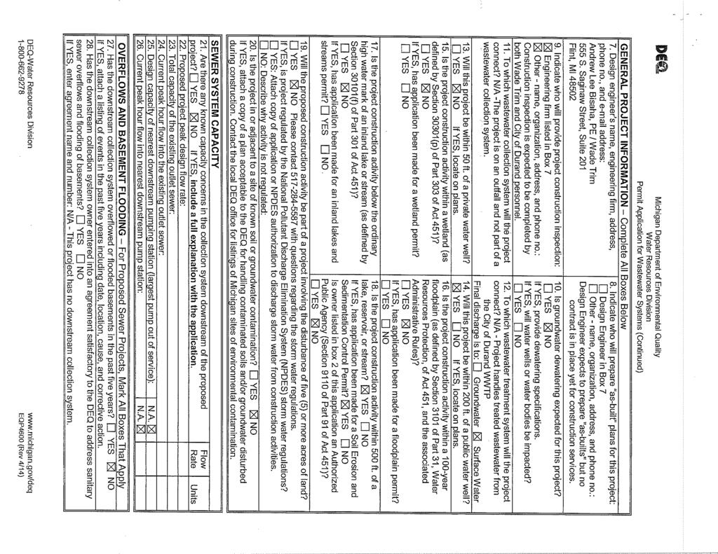
264
265

266 Item A Aluminum Cascade Aerator We are proposing an Aluminum Cascade Aerator system for this project. This system is designed as follows: Design Criteria Flow Rate to System 700 gpm max, 420 gpm average Number of Aerators 1 Design Flow per Aerator 800 gpm Size of Aerator 5 ft diameter x 5 ft 6 in high Inlet/Outlet Pipe Size 12 in Shipping Weight 230 pounds Operating Weight 1520 pounds Technical Description Cascade Aerators are a low-cost way of oxidizing iron and increasing dissolved oxygen. Water fed up to the top of the unit and free-falls through the aerator. Natural air draft sweeps by the falling water to increase the oxygen content while it is splashing down the unit. Dissolved solids such as iron are transformed to their oxidized states, enabling them to be removed by downstream equipment. In addition, some unwanted dissolved gases (e.g. carbon dioxide, hydrogen sulfide, VOC) are removed to reduce chemical requirements, stabilize ph, or eliminate objectionable tastes and odors. Key Features and Benefits No moving parts makes economical to operate and maintenance free. Aluminum construction eliminates painting and is corrosion resistant for simplified maintenance. Light weight for ease of installation. The following budget pricing includes: Round aluminum aerator of seven pass cascade design with three catch bowls and deflector plates. Flanged center inlet pipe with overflow baffle. All factory assembled. Aluminum collector pan. Freight to the job site. This proposal has been reviewed and is approved for issue by Michael Stotzer on October 16, Proposal No
CITY OF DE PERE PROJECT VOYAGEUR PARK PLAYGROUND BID DATE: FEBRUARY 1, 1:00 PM
 CITY OF DE PERE PROJECT 18-12 VOYAGEUR PARK PLAYGROUND BID DATE: FEBRUARY 1, 2018 @ 1:00 PM Bid documents, including plans and specifications, are available for download at www.questcdn.com. The QuestCDN
IMPROVEMENTS TO THE MUNICIPAL ELECTRIC SYSTEM OF THE CITY OF PIQUA, OHIO
 IMPROVEMENTS TO THE MUNICIPAL ELECTRIC SYSTEM OF THE CITY OF PIQUA, OHIO PROJECT MANUAL FOR CONTRACT NO. 016-00781-01 GAS TURBINE GENERATOR NO. 9 ROOF REPLACEMENT PROJECT FEBRUARY 2018 1001 Madison Avenue
CITY OF DE PERE PROJECT HVAC MAINTENANCE RE-BID BID DATE: MAY 5, 1:00 PM
 CITY OF DE PERE PROJECT 16-10 HVAC MAINTENANCE RE-BID BID DATE: MAY 5, 2016 @ 1:00 PM Bid documents, including plans and specifications, are available for download at www.questcdn.com. The QuestCDN website
Bidding Conditions. March 22, (Project# 0192) at the. Fresno Chaffee Zoo. Project : Warthog Exhibit. Located at. 894 West Belmont Avenue
 at the. Fresno Chaffee Zoo. Project : Warthog Exhibit. Located at. 894 West Belmont Avenue") Bidding Conditions March 22, 2018 (Project# 0192) at the Fresno Chaffee Zoo Project : Warthog Exhibit Located at 894 West Belmont Avenue Fresno, CA 93728 Page 1 of 8 DEFINITIONS Addendum - A document issued
Bidding Conditions March 22, 2018 (Project# 0192) at the Fresno Chaffee Zoo Project : Warthog Exhibit Located at 894 West Belmont Avenue Fresno, CA 93728 Page 1 of 8 DEFINITIONS Addendum - A document issued
SPECIFICATIONS FOR SIDEWALK REPLACEMENT PROGRAM
 SPECIFICATIONS FOR SIDEWALK REPLACEMENT PROGRAM CITY OF GALENA 101 GREEN STREET GALENA, IL 61036 MAY 2016 Project must be completed between 5 th and 30 th September 2016 CONTENTS Page # ADVERTISEMENT FOR
Bidding Conditions Attachment C
 Bidding Conditions Attachment C REV Date: November 9, 2018 Project Name (Permit Nos. xxx) at the Fresno Chaffee Zoo Project No. xxxx Located at 894 West Belmont Avenue Fresno, CA 93728 Page 1 of 8 DEFINITIONS
Specifications. For. Shermco Project Panora Substation Construction. Panora Municipal Electric Panora, Iowa. April 21, 2017 BID ISSUE
 Specifications For Shermco Project 91000154 Panora Substation Construction Panora Municipal Electric Panora, Iowa April 21, 2017 BID ISSUE Prepared Under Direction of: Michael Thorson Shermco Industries
DEAN + TYLER + BURNS ARCHITECTURE
 DEAN + TYLER + BURNS ARCHITECTURE May 17, 2017 Community Safe Room for the City Springville 580 Indian Crest Drive Indian Springs, AL 35124 tel.: 205.427.7890 email: m@rchitecture-e.com ADDENDUM NO. 3
TABLE OF CONTENTS. INVITATION TO BID thru INSTRUCTIONS TO BIDDERS thru
 TABLE OF CONTENTS PAGE INVITATION TO BID...00050-1 thru 00050-2 INSTRUCTIONS TO BIDDERS...00200-1 thru 00200-9 BID FORM...00400-1 thru 00400-8 Attachments: Bid Bond (EJCDC Form C-430)...00400.A-1 thru
NORTH BAY VILLAGE, FLORIDA INVITATION TO BID BID NO. NBV
 NORTH BAY VILLAGE, FLORIDA INVITATION TO BID FOR WATERMETERREPLACEMENT PROGRAM BID NO. NBV 2017-001 SEALED PROPOSALS WILL BE RECEIVED BY THE VILLAGE CLERK, 1666 KENNEDY CAUSEWAY,SUITE 300, NORTH BAY VILLAGE,
PROJECT MANUAL for Phantom Canyon Tunnel Repair Project. Location On Fremont County Road miles North of Intersection US Highway 50 with FCR 67
 August 28, 2018 PROJECT MANUAL for Phantom Canyon Tunnel Repair Project Location On Fremont County Road 67 7.5 miles North of Intersection US Highway 50 with FCR 67 Fremont County, Colorado OWNER: Fremont
DOCUMENT BID FORM. Village of Middle Point
 DOCUMENT 00300 BID FORM PROJECT IDENTIFICATION: Water Treatment Plant Replacement Village of Middle Point THIS BID IS SUBMITTED TO: Village of Middle Point 103 N. Adams Street Middle Point, OH 45863-0191
Mabton Canal Improvement Project MP Reservoir
 100% Submittal Mabton Canal Improvement Project MP 12.48 Reservoir Specifications Prepared By Sunnyside Valley Irrigation District 120 South 11th Street Sunnyside, WA 98944 June 2010 BIDDING REQUIREMENTS
SECTION BID FORM JACKSON AVENUE / 15TH STREET WATER MAIN REPLACEMENT
 ARTICLE 1 BID RECIPIENT 1.01 This Bid is submitted to: SECTION 00410 BID FORM JACKSON AVENUE / 15TH STREET WATER MAIN REPLACEMENT WESTERN VIRGINIA WATER AUTHORITY ATTN: Earl Smith Engineering Services
The Home Depot U.S.A., Inc. Instructions to Bidders
 The Home Depot U.S.A., Inc. Instructions to Bidders Home Depot Page 1 of 5 Article 1 Definitions 1.1 Bidding Documents include the Bidding Requirements and the proposed Contract Documents. The Bidding
CITY OF FLINT, MICHIGAN
 CITY OF FLINT, MICHIGAN DEPARTMENT OF PURCHASES & SUPPLIES PROJECT MANUAL FOR 2018 PHASE V HYDROVAC EXPLORATION Proposal No. 18-570 JANUARY 24, 2018 THIS PAGE INTENTIONALLY LEFT BLANK CITY OF FLINT Department
SECTION BID FORM LICK RUN INTERCEPTOR REHABILITATION
 SECTION 00410 BID FORM LICK RUN INTERCEPTOR REHABILITATION ARTICLE 1 BID RECIPIENT 1.01 This Bid is submitted to: WESTERN VIRGINIA WATER AUTHORITY ATTN: Earl Smith, P.E. Engineering Services Third Floor,
CITY OF DE PERE PROJECT CIPP SEWER LINING BID DATE: JANUARY 31, 1:00 PM
 CITY OF DE PERE PROJECT 19-03 CIPP SEWER LINING BID DATE: JANUARY 31, 2019 @ 1:00 PM Bid documents, including plans and specifications, are available for download at www.questcdn.com. The QuestCDN website
SECTION BID FORM. Construction of Water Mains: Jonestown, PA. Market Street Project No. W-1-19
 SECTION 00410 BID FORM Construction of Water Mains: Jonestown, PA. Market Street Project No. W-1-19 THIS BID IS SUBMITTED TO: CITY OF LEBANON AUTHORITY 2311 Ridgeview Road Lebanon, Pennsylvania 17042 1.01
DAG Architects, Inc. July South Walton Fire District Fleet Maintenance/Logistics Building & Training Tower
 DOCUMENT 001153 - REQUEST FOR QUALIFICATIONS 1.1 PURPOSE, LAWS, AND REGULATIONS A. The purpose of the Prequalification Procedure described in this Document is to provide Owner with a mechanism to evaluate
ADDENDUM NO. 1 FOR CITY OF CUMMING 900-HP RAW WATER INTAKE PUMP. ADDENDUM DATE: February 10, BID DATE: February 15, 2017, 11:30 a.m.
 ADDENDUM NO. 1 FOR CITY OF CUMMING 900-HP RAW WATER INTAKE PUMP ADDENDUM DATE: February 10, 2017 BID DATE: February 15, 2017, 11:30 a.m. This ADDENDUM is issued to institute the included changes and/or
Project Manual for East Bay Charter Township Phosphate Injection
 Project Manual for East Bay Charter Township Phosphate Injection East Bay Charter Township Grand Traverse County, Michigan January 21, 2019 Prepared by: Wade Trim, Inc. 10850 East Traverse Highway, Suite
00900 ADDENDUM #1. All Document Holders of Record. Date: February 16, Bayfield Waterline Replacement Project
 00900 ADDENDUM #1 Issued to: All Document Holders of Record Date: February 16, 2016 Project: Bayfield Waterline Replacement Project This Addendum forms a part of the Contract described above. The original
CITY OF MARSHALL, MINNESOTA
 Office of the Director of Public Works/City Engineer 344 West Main Street Marshall, MN 56258 507-537-6773 Fax: 507-537-6830 CITY OF MARSHALL, MINNESOTA SPECIFICATION AND BIDDING DOCUMENTS FOR REMOVAL OF
BID Addenda No. Date Issued Addenda No. Date Issued
 BID - 004113 BID TO: THE CITY AND BOROUGH OF JUNEAU 1. The undersigned Bidder proposes and agrees, if this Bid is accepted, to enter into an Agreement with the OWNER in the form included in the Contract
SECTION BID FORM. Garfield Street Drainage Improvements
 SECTION 00410 BID FORM Garfield Street Drainage Improvements ARTICLE 1 - BID RECIPIENT 1.01 This Bid is submitted to: City of Lindsborg, Kansas City Clerk s Office 101 S. Main Street Lindsborg, KS 67456
BID ADVERTISEMENT MARANACOOK LAKE OUTLET DAM MODIFICATIONS TOWNS OF READFIELD AND WINTHROP, MAINE
 BID ADVERTISEMENT MARANACOOK LAKE OUTLET DAM MODIFICATIONS TOWNS OF READFIELD AND WINTHROP, MAINE The Towns of Readfield and Winthrop, acting by and through the Maranacook Lake Outlet Dam Committee, are
THIRD STREET WATER MAIN REPLACEMENT PROJECT
 MARINA COAST WATER DISTRICT THIRD STREET WATER MAIN REPLACEMENT PROJECT CIP NO. OW-0240 June 2015 00010-1 Third Street Water Main Replacement Project CIP No. OW-0240 Document 00050 Marina Coast Water
BIDDING INFORMATION FOR HOLLY HILL ADMINISTRATION COMPLEX RENOVATION AND ADDITION. for the COUNTY OF ORANGEBURG. Project Number: FY
 BIDDING INFORMATION FOR HOLLY HILL ADMINISTRATION COMPLEX RENOVATION AND ADDITION for the COUNTY OF ORANGEBURG Project Number: FY13-1206 October 18, 2012 1180 Columbia Avenue Suite 201 29063 (803) 781-1451
ADDENDUM NUMBER ONE (1) December 6, The following Addendum shall be incorporated into the Contract Documents for the above referenced project.
 December 6, The following Addendum shall be incorporated into the Contract Documents for the above referenced project.") TO: ALL HOLDERS OF CONTRACT DOCUMENTS FOR: City of Carlsbad, New Mexico Sanitary Sewer Interceptor 118 Upgrades Phase I Wade M. Chacon P.E. HDR Project Manager/Engineer Bid # 2016-32 ADDENDUM NUMBER ONE
TO: ALL HOLDERS OF CONTRACT DOCUMENTS FOR: City of Carlsbad, New Mexico Sanitary Sewer Interceptor 118 Upgrades Phase I Wade M. Chacon P.E. HDR Project Manager/Engineer Bid # 2016-32 ADDENDUM NUMBER ONE
REVISED BID FORM. To Procurement Services, Room 1104, 900 East Broad Street, Richmond, Virginia:
 REVISED BID FORM SEALED BIDS WILL BE RECEIVED at the Department of Procurement Services, City Hall, 900 E. Broad Street, Rm. 1104, Richmond, Virginia 23219, UNTIL BUT NOT LATER THAN 2:30 P.M. ON February
Black Creek Consolidated Drain (Dirkes Drain)
") Black Creek Consolidated Drain (Dirkes Drain) CONTRACT SPECIFICATIONS ISSUED FOR BID Prepared For: Muskegon County Drain Commissioner Prepared By: Project No. 14-111 May 2016 Table of Contents Division
Black Creek Consolidated Drain (Dirkes Drain) CONTRACT SPECIFICATIONS ISSUED FOR BID Prepared For: Muskegon County Drain Commissioner Prepared By: Project No. 14-111 May 2016 Table of Contents Division
I. CHANGES TO THE SPECIFICATIONS REISSUED WITH THIS ADDENDUM
 I. CHANGES TO THE SPECIFICATIONS REISSUED WITH THIS ADDENDUM A. Delete the following pages and substitute the new pages which are attached and made a part of this Addendum. Changes to existing contract
NOTICE TO BIDDERS FOR
 CITY OF SAN LEANDRO STATE OF CALIFORNIA ENGINEERING AND TRANSPORTATION DEPARTMENT NOTICE TO BIDDERS FOR MONARCH BAY DRIVE BRIDGE REPAIR PROJECT NO. 12-144-38-324 BID NO. 12-13.013 1. BID OPENING: The bidder
INSTRUCTIONS TO BIDDERS
 INSTRUCTIONS TO BIDDERS CONTENTS I. Bid Documents II. Ethical Business Practices III. Contractor Qualifications IV. Performance and Quality Standards V. Bid Evaluation VI. Contract Award VII. Work Operations
BID FORM This Bid is submitted to: City of Glasgow 126 East Public Square Glasgow, KY 42141
 BID FORM PROJECT DESCRIPTION Ellis Avenue Stream Improvements City of Glasgow, KY PROJECT NUMBER GRW Project No.: 4339 ARTICLE 1 BID RECIPIENT 1.01 This Bid is submitted to: City of Glasgow 126 East Public
WASTEWATER TREATMENT PLANT MICROTURBINES AND DIGESTER GAS CONDITIONING SKID EQUIPMENT
 MARIN COUNTY, CALIFORNIA CONTRACT DOCUMENTS FOR WASTEWATER TREATMENT PLANT MICROTURBINES AND DIGESTER GAS CONDITIONING SKID EQUIPMENT JOB NO. 14600-04 February 2015 DISTRICT BOARD Rabi Elias President
CONTRACT DOCUMENTS AND BID FORM. FPL Remediation and Redevelopment PROJECT IDENTIFICATION:
 CONTRACT DOCUMENTS AND BID FORM PROJECT IDENTIFICATION: THIS BID IS SUBMITTED TO: MANDATORY PRE-BID CONFERENCE: FPL Remediation and Redevelopment City of Biddeford c/o Brian Phinney Environmental Codes
City of Ketchum and Sun Valley Water and Sewer District
 City of Ketchum and Sun Valley Water and Sewer District CITY OF KETCHUM AND SUN VALLEY, ID Headworks Improvements - Screen and Washer/Compactor Procurement Issued for Bid February 2018 HDR Project No.
HURLEY DECENTRALIZED WASTEWATER TREATMENT PLANT REHABILITATION
 HURLEY DECENTRALIZED WASTEWATER TREATMENT PLANT REHABILITATION Project Manual prepared for JACKSON COUNTY UTILITY AUTHORITY PREPARED BY: COMPTON ENGINEERING, INC. 1706 CONVENT AVE. PASCAGOULA, MISSISSIPPI
BIDDING DOCUMENTS KRULL DITCH/PARK AVENUE CULVERT REPLACEMENT PROJECT WHEELER, INDIANA
 BIDDING DOCUMENTS FOR THE KRULL DITCH/PARK AVENUE CULVERT REPLACEMENT PROJECT IN WHEELER, INDIANA SEPTEMBER 8, 2017 PREPARED BY: PORTER CO. DEPT. OF DEVELOPMENT & STORM WATER MANAGEMENT 155 INDIANA AVE.,
SECTION BID FORM
 Attachment 1 Contract 13 Addendum 3 ARTICLE 1 BID RECIPIENT 1.01 This Bid is submitted to: SECTION 00300 BID FORM CITY OF CAPE CORAL NORTH 2 UTILITIES EXTENSION PROJECT CONTRACT 13 City of Cape Coral,
PROJECT MANUAL VILLAGE OF ADDISON STREETSCAPE IMPROVEMENTS. Contract 1 GENERAL CONSTRUCTION
 PROJECT MANUAL VILLAGE OF ADDISON STREETSCAPE IMPROVEMENTS Contract 1 GENERAL CONSTRUCTION Prepared for: VILLAGE OF ADDISON 35 TUSCARORA STREET ADDISON, NY 14801 Prepared by: LARSON DESIGN GROUP 1 West
Powell Substation Control Panels Replacement Project
 PAGE UTILITY ENTERPRISES 640 Haul Road Page, Arizona 86040 Powell Substation Control Panels Replacement Project Volume I - Bidding Documents Bid #206 Bidder s Name and Address May 2016 Intermountain Consumer
OCONEE COUNTY PROCUREMENT OFFICE 415 S. PINE STREET, ROOM 100 WALHALLA, SC Robyn M. Courtright, CPPO, Procurement Director
 OCONEE COUNTY PROCUREMENT OFFICE 415 S. PINE STREET, ROOM 100 WALHALLA, SC 29691 Robyn M. Courtright, CPPO, Procurement Director Tronda Spearman, CPPB, Assistant Procurement Director Telephone: 864-638-4141
Lincoln Charter Township Berrien County, Michigan GLENLORD BEACH PARK IMPROVEMENTS 2019
 Berrien County, Michigan GLENLORD BEACH PARK IMPROVEMENTS 2019 December, 2018 TABLE OF CONTENTS Section Description Pages FRONT END DOCUMENTS DIVISION 1 GENERAL 00015 - List of Drawings... 1 00100 - Bid
Sunnycrest Manor Roosevelt Street Dubuque, IA Sunnycrest Manor Kitchen Ventilation MEP Engineers Project #1735
 Sunnycrest Manor 2375 Roosevelt Street Dubuque, IA 52001 Sunnycrest Manor Kitchen Ventilation MEP Engineers Project #1735 Sunnycrest Manor Kitchen Ventilation SUNNYCREST MANOR KITCHEN VENTILATION 2375
Main Building Auditorium
 Main Building Auditorium Theatre and Lighting Upgrade Moberly Area Community College 101 College Avenue Moberly, Missouri This document contains all necessary instructions and specifications to perform
CONTRACT DOCUMENTS AND TECHNICAL SPECIFICATIONS FOR
 CONTRACT DOCUMENTS AND TECHNICAL SPECIFICATIONS FOR PARKVIEW / LANTRIP RETAINING WALL REPLACEMENT Project Number KIL001C ISSUED FOR BID Submission Deadline: Tuesday, December 19 th, 2017 at 2 p.m. Submit
PROJECT MANUAL FOR: CP AGRICULTURAL ENGINEERING RAIN TOWER REPAIRS CP HULSTON HALL STAIR TOWER REPAIRS
 ADDENDUM #01 DATE: MAY 6, 2016 Page 1 of 2 TO CONTRACT DOCUMENTS ENTITLED: PROJECT MANUAL FOR: CP151322 AGRICULTURAL ENGINEERING RAIN TOWER REPAIRS CP160372 HULSTON HALL STAIR TOWER REPAIRS AT UNIVERSITY
A D D E N D U M. REPLACE: Project Summary with attached revised Project Summary. 1 Specification Section Project Summary
 A D D E N D U M 1 TO All Plan Holders ISSUE DATE 20 January 2017 PROJECT # 15-028 REGARDING Switchgear Replacement NARRATIVE PAGES 1 15-02812 KVa Switchgear Replacement Project SPECIFICATION PAGES 10 DRAWING
This Addendum is directed to all prime Contract Bidders, and all others to whom Drawings and Specifications have been issued by the Architect.
 North Campus Entrance and related work Wallace State Community College ADDENDUM 3 PART 1 - GENERAL Project: North Campus Entrance and related work [B.C. # 2016259] Owner: Wallace State Community College
August 19, Addendum No. 2 Roosevelt Hall Interior Renovation Brooklyn College Project No.: BY
 The City University Of New York August 19, 2010 Addendum No. 2 Roosevelt Hall Interior Renovation Brooklyn College Project No.: BY600-006 This Addendum is for the purpose of conveying the below Documents
ADVERTISEMENT TO BID PARTIAL
 ADVERTISEMENT TO BID The City of Elkton will receive separate, sealed Bids for their East Main Street Lift Station Generator Pad Addition Project until 10:30 a.m. local time, Tuesday, January 8, 2019 at
Addendum No. 1 Issue Date: March 29, 2016
 Addendum No. 1 Issue Date: Project: Bonson and Short Street Reconstruction Contract: #1-16 Owner: City of Platteville, Wisconsin Engineer: Delta 3 Engineering, Inc. Daniel J. Dreessens, P.E. 875 South
Oxford & Area Trails Association River Philip Bridge Construction, Oxford, N.S Project No.: OATA003 SECTION 1.0 INSTRUCTION TO BIDDERS
 1.1 INSTRUCTION TO BIDDERS Oxford & Area Trails Association River Philip Bridge Construction, Project No.: OATA003 INSTRUCTIONS TO BIDDERS August 7, 2015 SECTION 1.0 INSTRUCTION TO BIDDERS 1.2 TENDER DOCUMENTS
Richmond Heights, MO. Prepared for: City of Richmond Heights Chris Boyd, P.E., Public Works Director 7997 Elinor Ave. Richmond Heights, MO 63117
 PROJECT MANUAL 2016 CONCRETE SLAB REPLACEMENT PROGRAM Richmond Heights, MO Prepared for: City of Richmond Heights Chris Boyd, P.E., Public Works Director 7997 Elinor Ave. Richmond Heights, MO 63117 Prepared
Bidders Name: DOCUMENT 330 BID FORM
 Bidders Name: DOCUMENT 330 BID FORM TO: The City of Topeka, Kansas Contracts & Procurement Division 215 S.E. 7th St., Room 60 Topeka, Kansas 66603 Project No. and Description: 1. The undersigned Bidder
THE CITY OF LAKE FOREST
 THE CITY OF LAKE FOREST SPECIFICATIONS FOR Barrell Memorial Gate Restoration Project at the Lake Forest Cemetery January 4, 2019 TABLE OF CONTENTS SECTION 00030... 4 ADVERTISEMENT FOR BIDS... 4 SECTION
SPECIFICATIONS & CONTRACT DOCUMENTS Sanitary Sewer Manhole Replacement and Bypass Contract 2013 FOR. The Town of Tyrone
 SPECIFICATIONS & CONTRACT DOCUMENTS Sanitary Sewer Manhole Replacement and Bypass Contract 2013 FOR The Town of Tyrone March 2013 Map of Approximate Vicinity Where Sewer Manhole Replacement and By Pass
JUDD STREET LIFT STATION DEWATERING CONTRACT
 JUDD STREET LIFT STATION DEWATERING CONTRACT MONTCALM COUNTY, MICHIGAN MAY 23, 2018 CITY OF GREENVILLE JOB NO. 401-590-975.281 PREPARED BY: CITY OF GREENVILLE ENGINEERING DEPARTMENT 411 S. LAFAYETTE GREENVILLE,
ELECTRONIC COPY NOT FOR BIDDING PURPOSES ALL BIDDERS SHALL BE ON THE OFFICIAL BIDDER'S LIST
 SECTION 00000 TABLE OF CONTENTS CITY OF PICAYUNE ROOF REHABILITATION FOR PICAYUNE POLICE DEPARTMENT PICAYUNE, MS DIVISION 0 - BIDDING AND CONTRACT REQUIREMENTS 00001... Advertisement for Bids 00100...
MULLER LANE EAST BROCKLISS SLOUGH BRIDGE SEWER FORCE MAIN RELOCATION
 CONTRACT DOCUMENTS and CONSTRUCTION SPECIFICATIONS for MULLER LANE EAST BROCKLISS SLOUGH BRIDGE SEWER FORCE MAIN RELOCATION DOUGLAS COUNTY SEWER IMPROVEMENT DISTRICT NO. 1 ZEPHYR COVE, NEVADA Rob Hopkins,
Middle School Sewer Main Improvements Project Contract Documents & Specifications
 Middle School Sewer Main Improvements Project Contract Documents & Specifications For: Prepared By: Hardin County Water District No. 1 1400 Rogersville Road Radcliff, KY. 40160 Phone: 270-351-3222 FAX:
SECTION CONTRACT DOCUMENTS TABLE OF CONTENTS
 SECTION 00020 CONTRACT DOCUMENTS TABLE OF CONTENTS PAGE(S) BIDDING REQUIREMENTS, CONTRACT FORMS, AND CONDITIONS OF THE CONTRACT SECTION PAGE(S) PART 1 - BIDDING REQUIREMENTS 00010 Title Page... 00001-1
DEMOLITION BID. BID OPENING November 20, 2018, 8:00pm. Village of Germantown 306 Prairie St. Germantown, IL 62245
 DEMOLITION BID BID OPENING November 20, 2018, 8:00pm Village of Germantown 306 Prairie St. Germantown, IL 62245 Important Bids will not be reviewed without the following information fully completed and
I INVITATION TO BID City of Fort Morgan Water Distribution Department Waterline Isolation Project
 I INVITATION TO BID Water Distribution Department The Water Distribution Department is accepting sealed bids for a until 2:45 p.m. (our clock) on March 8, 2018 at City Hall located at 110 Main Street,
Both envelopes must have the following information in the lower left hand corner:
 SECTION 001116 INVITATION TO BID The City of Morgantown is requesting a bid for masonry restoration for the City Hall Building in Morgantown, WV. The Project is for building envelope rehabilitation including
CONTRACT DOCUMENTS MARION COUNTY BOARD OF SUPERVISORS REPAIR AND RE-ROOF OF EXISTING CAFETERIA AND INDUSTRIAL BUILDING MARION COUNTY BUSINESSPLEX
 CONTRACT DOCUMENTS MARION COUNTY BOARD OF SUPERVISORS REPAIR AND RE-ROOF OF EXISTING CAFETERIA AND INDUSTRIAL BUILDING MARION COUNTY BUSINESSPLEX MARION COUNTY, MS MARCH 2019 1574 HWY. 98 EAST COLUMBIA,
GYMNASIUM RENOVATION WASHINGTON HIGH SCHOOL
 PROJECT MANUAL FOR CONSTRUCTION OF GYMNASIUM RENOVATION WASHINGTON HIGH SCHOOL WASHINGTON COMMUNITY SCHOOLS Washington, Indiana PROJECT MANUAL FOR CONSTRUCTION OF GYMNASIUM RENOVATION WASHINGTON HIGH SCHOOL
Standard Specifications and Details for Street and Utility Construction
 Standard Specifications and Details for Street and Utility Construction 2013 Edition City of Sheridan 55 Grinnell Plaza PO Box 848 Sheridan, WY 82801 (307) 674-6483 TABLE OF CONTENTS TABLE OF CONTENTS
Attached please find the revised Plan Sheet C3 Proposed Conditions Plan.
 ADDENDUM NO. 1 124002-4A RE: FROM: TO: Depot Street Drainage Improvements Charlestown, New Hampshire DuBois & King, Inc. P.O. Box 339 Randolph, Vermont 05060 (802) 728-3376 Prospective Bidders DATE: June
BOILER PLANT UPGRADES. PROJECT MANUAL PEI Project No. 1109
 City of Portsmouth PORTSMOUTH CITY HALL 1 Junkins Avenue Portsmouth, NH 03801 BOILER PLANT UPGRADES PROJECT MANUAL PEI Project No. 1109 May 2013 PO Box 4774 Portsmouth, NH 03802 Portsmouth City Hall May
City of Eagle Point 2017 Paving Instruction to Bidders
 City of Eagle Point 2017 Paving Instruction to Bidders Issued: August 2, 2017 Closing Date and Time: Wednesday August 16, 2016 at 2:00 pm Project Summary The City of Eagle Point is requesting bids for
CITY OF HOLLYWOOD CONTRACT DOCUMENTS AND SPECIFICATIONS FOR INFLOW/INFILTRATION (I/I) PROGRAM - MANHOLE REPAIRS AUGUST 2016.
 PROGRAM - MANHOLE REPAIRS AUGUST 2016.") PROJECT CITY OF HOLLYWOOD CONTRACT DOCUMENTS AND SPECIFICATIONS FOR INFLOW/INFILTRATION (I/I) PROGRAM - MANHOLE REPAIRS AUGUST 2016 Prepared by: ENGINEERING AND CONSTRUCTION SERVICES DIVISION 1621 N 14
PROJECT CITY OF HOLLYWOOD CONTRACT DOCUMENTS AND SPECIFICATIONS FOR INFLOW/INFILTRATION (I/I) PROGRAM - MANHOLE REPAIRS AUGUST 2016 Prepared by: ENGINEERING AND CONSTRUCTION SERVICES DIVISION 1621 N 14
BID PROPOSAL FOR TOWN OF HIGHLAND PARK, TEXAS FOR 2014 WATER MAIN AND SEWER MAIN REPLACEMENT IN EASEMENTS
 BID PROPOSAL FOR TOWN OF HIGHLAND PARK, TEXAS FOR 2014 WATER MAIN AND SEWER MAIN REPLACEMENT IN EASEMENTS (Easement 6 & 11, 4200 block of Versailles Avenue and Belclaire Avenue and the 4300 block of Westway
PUBLIC SAFETY BUILDING BUILDING DEMOLITION
 Contract No. BE19-117 File No. 2003 SECTION 00005 - TABLE OF CONTENTS DIVISION 0 - BIDDING AND CONTRACT REQUIREMENTS, CONTRACT FORMS, AND CONDITIONS OF THE CONTRACT BIDDING and CONTRACT REQUIREMENTS No.
CITY OF AZUSA. Azusa Gateway Improvements (CIP #66111B)
") CITY OF AZUSA Azusa Gateway Improvements (CIP #66111B) CONTRACT DOCUMENTS TABLE OF CONTENTS Page No. NOTICE INVITING BIDS... 1 INSTRUCTIONS TO BIDDERS... 3 BID FORM... 10 BID SCHEDULE... 10 CONTRACTOR
CITY OF AZUSA Azusa Gateway Improvements (CIP #66111B) CONTRACT DOCUMENTS TABLE OF CONTENTS Page No. NOTICE INVITING BIDS... 1 INSTRUCTIONS TO BIDDERS... 3 BID FORM... 10 BID SCHEDULE... 10 CONTRACTOR
REQUEST FOR PROPOSALS AND STATEMENT OF QUALIFICATIONS IMPACT FEE STUDY
 REQUEST FOR PROPOSALS AND STATEMENT OF QUALIFICATIONS IMPACT FEE STUDY June 1, 2018 The City of Rhome is now accepting sealed Request for Proposals and Statement of Qualifications (RFQ) for New Water &
DOCUMENT BID PROPOSAL
 DOCUMENT 00 41 13 BID PROPOSAL TO: SAN JOSE / EVERGREEN COMMUNITY COLLEGE DISTRICT, a California Community College District, acting by and through its Board of Trustees ("the District"). FROM: (Name of
A new Proposal Form is being issued with this Addendum, the following is an explanation of the changes, disregard originally issued form.
 Courtyards Phase ADDENDUM NO. 1 May 2, 2016 PROJECT: Courtyards at the Oaks Phase 2 Paving & Incidental Drainage Improvements BID DATE: Tuesday, May 3, 2016, at 2:00 PM City Hall, City of Derby 611 Mulberry
CITY OF PANAMA CITY BEACH WWTF INFLUENT SCREENS REPLACEMENT April 14, 2017
 CITY OF PANAMA CITY BEACH WWTF INFLUENT SCREENS REPLACEMENT April 14, 2017 ADDENDUM NO. 1 (This Form Must Be Signed and Submitted With Bid Form) Addendum No. 1 addresses the following issues: QUESTIONS
CITY OF LAKE FOREST PARK EXTERIOR PAINTING OF CITY HALL BUILDING. Bid Document. Specifications, Proposal and Contract Documents
 CITY OF LAKE FOREST PARK EXTERIOR PAINTING OF CITY HALL BUILDING Bid Document Specifications, Proposal and Contract Documents July 2013 CITY OF LAKE FOREST PARK Exterior Painting of City Hall Building
CONSTRUCTION DOCUMENTS FOR THREE TRENCH DRAIN MODIFICATIONS. City of Des Peres Manchester Road Des Peres, Missouri 63131
 CONSTRUCTION DOCUMENTS FOR THREE TRENCH DRAIN MODIFICATIONS City of Des Peres 12325 Manchester Road Des Peres, Missouri 63131 Prepared by City Engineer January 2011 1 CONSTRUCTION DOCUMENTS I. Bid Announcement
SPECIFICATIONS PROPOSAL AND CONTRACT DOCUMENTS
 SPECIFICATIONS PROPOSAL AND CONTRACT DOCUMENTS WASTEWATER TREATMENT PLANT RENOVATION Prepared for: WATER WORKS AND SEWER BOARD OF THE CITY OF GENEVA JULY, 2018 Prepared by: Andalusia, Alabama TABLE OF
Highlands Housing Authority
 Highlands Housing Authority 215 Shore Drive, Highlands, New Jersey 07732 TELEPHONE: (732) 872-2022 FAX: (732) 291-8743 REQUEST FOR PROPOSALS for CONCRETE SIDEWALK REPAIRS at JENNIE PARKER MANOR HIGHLANDS,
IMMEDIATE RESPONSE REQUESTED
 DATE: June 1, 2018 IMMEDIATE RESPONSE REQUESTED ADDENDUM NO. 3 Project No. 833450 Owner: City of Dexter Project: 2018 Wastewater Treatment Plant Improvements ADDENDUM ACKNOWLEDGMENT Upon receipt of this
Request for Proposal Internet Access Columbus Urban League
 Request for Proposal Internet Access Columbus Urban League 1 REQUEST FOR PROPOSAL Internet Access Columbus Urban League The Columbus Urban League invites vendors to submit proposals in accordance with
Aurora Public Schools. Modular Placement at Crawford Elementary & CDC Laredo. Project Manual
 Aurora Public Schools Modular Placement at Crawford Elementary & CDC Laredo Project Manual Bid Number 2447-13 April 30, 2013 Table of Contents Section Document Title 00020 00100 Invitation to Bid Instructions
City of Eagle Point South Shasta Pedestrian Bridge Instruction to Bidders
 City of Eagle Point South Shasta Pedestrian Bridge Instruction to Bidders Issued: November 15, 2017 Closing Date and Time: January 16, 2018, at 2:00 pm Project Summary The City of Eagle Point is requesting
CENTENNIAL HALL FLOOR RENOVATION
 Contract No. BE17-156 File No. 1935 ENGINEERING DEPARTMENT SECTION 00005 - TABLE OF CONTENTS DIVISION 0 - BIDDING AND CONTRACT REQUIREMENTS, CONTRACT FORMS, AND CONDITIONS OF THE CONTRACT BIDDING and CONTRACT
PUBLIC WORKS DEPARTMENT
 PUBLIC WORKS DEPARTMENT BID FORMS FOR 2013-14 CURB, GUTTER AND SIDEWALK REPAIR AND CURB-RAMP INSTALLATION PW 13-28 PLEASE USE BLACK INK WHEN YOU PREPARE THESE FORMS DO NOT DETACH ANY OF THIS MATERIAL THIS
MEMORANDUM. Taylor Schoel with Walter Schoel Engineering. DATE: August 29, Addendum 1 - Green Drive Culvert Replacement.
 MEMORANDUM TO: FROM: Bidders Taylor Schoel with Walter Schoel Engineering DATE: August 29, 2013 SUBJECT: Addendum 1 - Green Drive Culvert Replacement The following is part of Addendum 1 and should be included
Powell Substation 21.6kV Switching Modification Project
 PAGE UTILITY ENTERPRISES 640 Haul Road Page, Arizona 86040 Powell Substation 21.6kV Switching Modification Project Volume I - Bidding Documents Bid #207 Bidder s Name and Address October 2016 Intermountain
Powell Substation Transformer T2 Replacement Project
 PAGE UTILITY ENTERPRISES 640 Haul Road Page, Arizona 86040 Powell Substation Transformer T2 Replacement Project Volume I - Bidding Documents Bid #226 Bidder s Name and Address July 2018 Intermountain Consumer
STANDARD CONTRACT DOCUMENTS. and TECHNICAL SPECIFICATIONS. for. Ultraviolet Disinfection Replacement. Northfield, Minnesota
 STANDARD CONTRACT DOCUMENTS and TECHNICAL SPECIFICATIONS for Ultraviolet Disinfection Replacement Northfield, Minnesota 2016 City Project #WSTR2016-J07 Bolton & Menk Project #M23.112089 ENGINEERING STANDARD
 extrudesection 00301 BID FORM PROJECT IDENTIFICATION: CONSTRUCTION OF PROPOSED DRAINAGE IMPROVEMENTS THIS BID IS SUBMITTED TO: THE CITY OF FREDERICKSBURG, TEXAS, herein after referred to as OWNER. 1. Enter
PW # 2-18 TENDER FOR SUPPLY & APPLY CRUSHED GRANITE
 Tender Number: PW #2-18 Sealed Tenders will be clearly marked and received by: Corporation of the Township of Ryerson 28 Midlothian Road Burk s Falls, Ontario P0A 1C0 (705) 382-3232 Closing Date: THURSDAY
BOILER REPLACEMENT AT SCHOOL OF ENGINEERING FOR ALABAMA A&M UNIVERSITY. Normal, Alabama
 BOILER REPLACEMENT AT SCHOOL OF ENGINEERING FOR ALABAMA A&M UNIVERSITY Normal, Alabama MIMS ENGINEERING, INC., 112B Southside Square, Huntsville, AL 35801 May 2, 2018 BOILER REPLACEMENT AT SCHOOL OF ENGINEERING
Refer to Section Proposal Form/All Trades (issued) a. Revised Alternate No. 2 b. Added Alternate No. 3
 a. Revised Alternate No. 2 b. Added Alternate No. 3") WAKELY ASSOCIATES, INC. ADDENDUM NO. ONE ARCHITECTS 30500 Van Dyke Avenue Suite 209 Warren, Michigan 48093 NEW LED LIGHTING Page 1 of 1 (write up only) January 23, 2018 ADDENDUM NO. ONE to the plans and
WAKELY ASSOCIATES, INC. ADDENDUM NO. ONE ARCHITECTS 30500 Van Dyke Avenue Suite 209 Warren, Michigan 48093 NEW LED LIGHTING Page 1 of 1 (write up only) January 23, 2018 ADDENDUM NO. ONE to the plans and