Run-on and Run-off Control System Plan
|
|
|
- Carmella Stanley
- 5 years ago
- Views:
Transcription
1 Run-on and Run-off Control System Plan For Compliance with the Coal Combustion Residuals Rule (40 CFR ) Pawnee Station CCR Landfill Public Service Company of Colorado Denver, Colorado October 17, 2016 PREPARED FOR PAWNEE STATION Morgan County Road 24, Brush, Colorado 80723
2 PSCo Run-on and Run-off Control System Plan Pawnee Station CCR Landfill Table of Contents 1.0 Introduction Facility Description Regulatory Requirements Run-on / Run-off Controls for CCR Landfill Description of CCR Landfill and Drainage Area Description of Existing Run-on / Run-off Controls Run-on Controls Run-off Controls Surface Water Run-off Model Rainfall Data Weighted Curve Number Time of Concentration Evaporation Pond Evaluation of Existing Run-on / Run-off Controls Improvements to Existing Run-on / Run-off Controls Professional Engineer Certification... 7 List of Tables Table 1. Rainfall Data... 3 Table 2. Summary of North Area Breakdown... 5 Table 3. Summary of South Area Breakdown... 5 List of Figures Figure 1. Pawnee Power Station Facility Location Map... 2 Figure 2. Stormwater Drainage Map... 4 List of Appendices Appendix A Appendix B Appendix C HEC-HMS Model Results NOAA Rainfall Data Soil Conservation District Soil Report i
3 PSCo Run-on and Run-off Control System Plan Pawnee Station CCR Landfill Table of Abbreviations and Acronyms Abbreviation CCR CFR cfs CN EPA HEC-HMS HSG Landfill NAIP NOAA PSCo RCRA SCS Definition Coal Combustion Residuals Code of Federal Regulations cubic feet per second Curve Number Environmental Protection Agency Hydrologic Engineering Center Hydrologic Modeling System Hydrologic Soil Group Pawnee Landfill National Agricultural Imagery Program National Oceanic and Atmospheric Administration Public Service Company of Colorado Resource Conservation and Recovery Act Soil Conservation Service TR-20 Technical Release 20 TR-55 Technical Release 55 ii
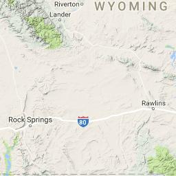
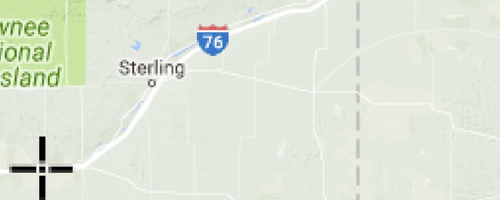
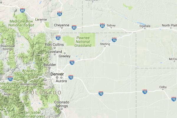
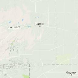
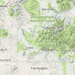
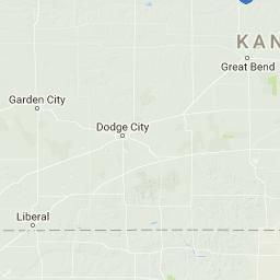
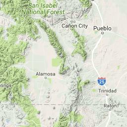
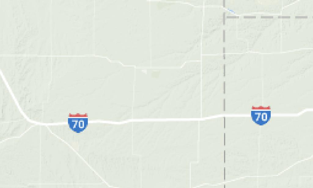
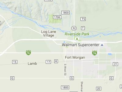
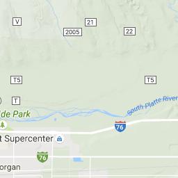
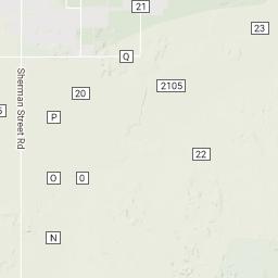
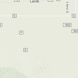
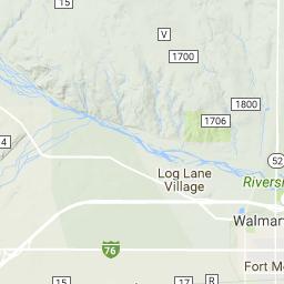
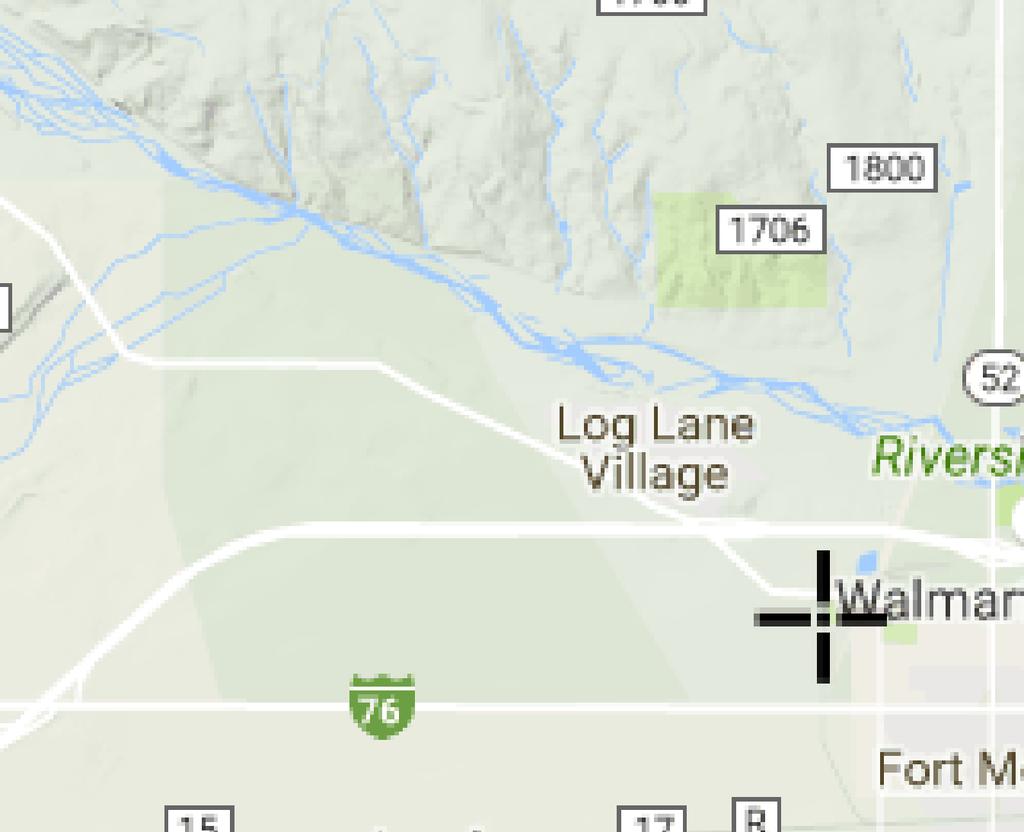
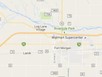
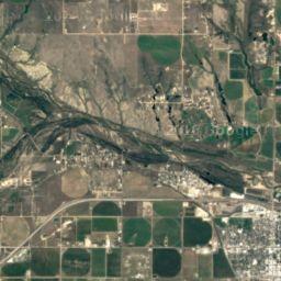
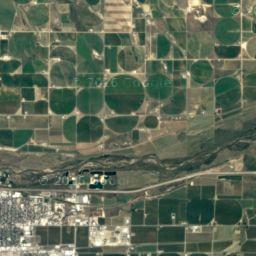
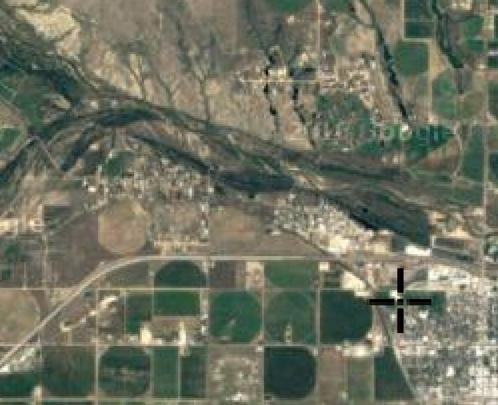
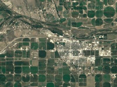
4 PSCo Run-on and Run-off Control System Plan Pawnee Station CCR Landfill 1.0 Introduction On April 17, 2015, the U.S. Environmental Protection Agency (EPA) published regulations under Subtitle D of the Resource Conservation and Recovery Act (RCRA) meant to control the safe disposal of coal combustion residuals (CCR) generated by coal fired electric utilities. The rule defines a set of requirements for the disposal and handling of CCRs within CCR units (defined as either landfills or surface impoundments). The requirements include preparation of a Run-on and Run-off Control System Plan for all existing and new CCR landfills. This Run-on and Run-off Control System Plan was prepared for the CCR landfill at the Pawnee Station operated by Public Service Company of Colorado (PSCo), an Xcel Energy Company. It was prepared in accordance with the requirements of 40 Code of Federal Regulations (CFR) The regulation requires that an initial Run-on and Run-off Control System Plan be prepared no later than October 17, Facility Description The Pawnee Station landfill is located at the Pawnee Station Power Plant at Morgan County Road 24, Brush, Colorado, approximately one-half mile southwest of the main power plant building. Pawnee Station is approximately four miles southwest of Brush, Colorado. Figure 1 provides a Site Location Map. The landfill began operating in 1981 and has been in use ever since. The footprint of the landfill was excavated for borrow soils for the original construction of the power plant, such that the base elevation is below the surrounding grade. The total area of the original excavation is approximately 48 acres. The northern portion is the CCR landfill, which includes an evaporation pond and an earthen dike separating the CCR landfill from the southern portion of the excavated footprint. The southern portion was historically used for disposal of lime sludge generated from the treatment of raw water for use in the plant. Approximately 150,000 tons of fly ash and 20,000 tons of bottom ash are generated annually and disposed at the landfill. An evaporation pond is located on the southern end of the CCR landfill. The pond is lined with a geosynthetic clay liner. Stormwater falling on the CCR landfill flows to the evaporation pond. Stormwater falling on the southern lime sludge landfill is directed north to the earthen dike. The dike is designed as a porous dike and is intended to pass water from the lime sludge landfill to the evaporation pond. 1.2 Regulatory Requirements 40 CFR requires that an owner or operator of an existing or new CCR landfill, or any lateral expansion of a CCR landfill, design, construct, operate, and maintain: 1) a run-on control system to prevent flow onto the active portion of the CCR unit during the peak discharge from a 24-hour, 25-year storm; 2) a run-off control system from the active portion of the CCR unit to collect and control at least the water volume resulting from a 24-hour, 25-year storm; and 3) a run-off control system designed to handle run-off so that it does not cause a discharge of pollutants to waters of the United States that is in violation of the requirements of the National Pollutant Discharge Elimination System (NPDES) under Section 402 of the Clean Water Act. 1

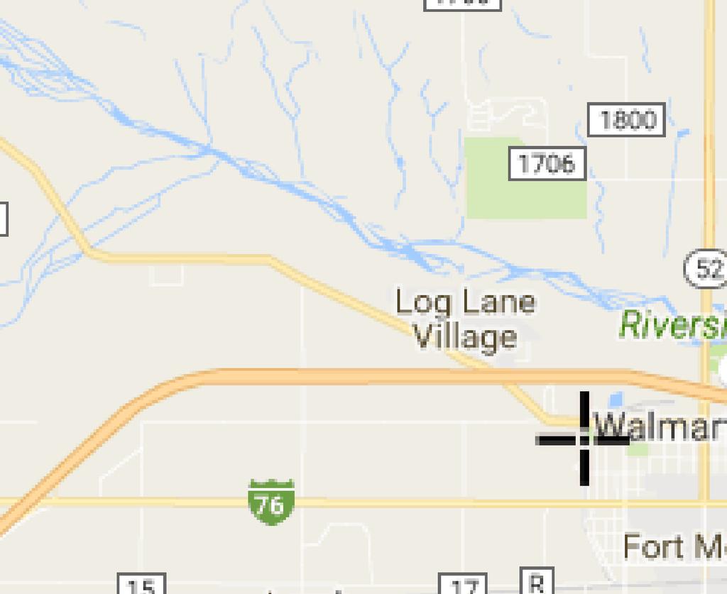
5 PSCo Run-on and Run-off Control System Plan Pawnee Station CCR Landfill Figure 1. Pawnee Power Station Facility Location Map 2
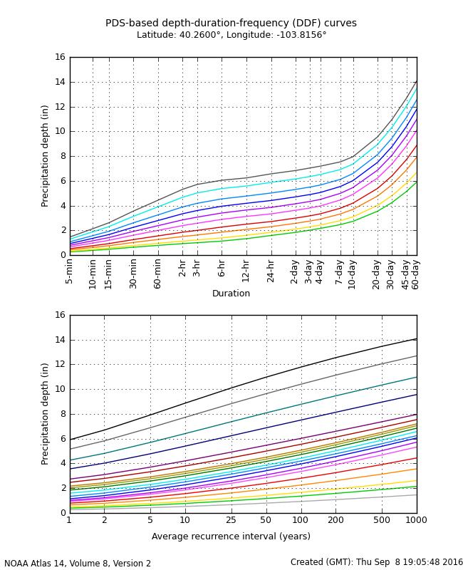
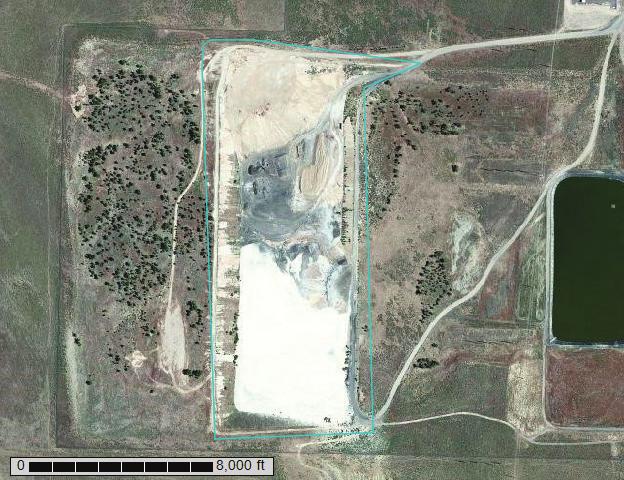
6 PSCo Run-on and Run-off Control System Plan Pawnee Station CCR Landfill 2.0 Run-on / Run-off Controls for CCR Landfill A hydrologic and hydraulic analysis was completed for the active portion of the CCR landfill unit in accordance with 40 CFR Per the active portion means that part of the CCR unit that has received or is receiving CCR or non-ccr waste and that has not completed closure in accordance with The evaluation included preparation of a surface water run-off model using Hydrologic Engineering Center Hydrologic Modeling System (HEC- HMS) developed by the United States Army Corps of Engineers. This modeling system was used to determine whether existing run-on and run-off control systems meet the required criteria for controlling run-on and run-off from the 24-hour, 25-year storm event. The evaluation was completed using the best available information at the time and was based on a photometric topographical survey from December 12, 2014 with portions updated August 13, Description of CCR Landfill and Drainage Area Based on the survey data, the landfill active area is approximately acres. The evaporation pond is approximately 3.3 acres in size. The porous dike separating the CCR landfill from the lime sludge landfill is approximately 1.7 acres. The active landfill area and delineated drainage basin is shown on Figure Description of Existing Run-on / Run-off Controls Run-on Controls The CCR landfill is bounded on the east and west sides by a perimeter berm, natural topography on the northern end and the earthen dike on the southern end to limit stormwater run-on/run-off to the landfill Run-off Controls An evaporation pond is located on the southern end of the CCR landfill. The landfill is graded to direct stormwater to the evaporation pond. 2.3 Surface Water Run-off Model A surface water run-off model was prepared using HEC HMS version 4.2, which utilizes parameters developed following the Soil Conservation Service (SCS) Technical Release 55 (TR- 55) for computing curve numbers and times of concentration in order to generate runoff hydrographs. The model is included as Appendix A. A detailed discussion of the information input into the model is provided below Rainfall Data Rainfall data was taken from the National Oceanic and Atmospheric Administration (NOAA) Precipitation Frequency Data Server. Rainfall data input into the model included the 2-year and 25-year, 24 hour storm events. The 24-hour precipitation amounts are summarized in Table 1, and the information from the NOAA Precipitation Frequency Data Server is included as Appendix B. Table 1. Rainfall Data 24 Hour Rainfall Event Precipitation (inches) 2- year year

7 PSCo Run-on and Run-off Control System Plan Pawnee Station CCR Landfill Figure 2. Stormwater Drainage Map 4
8 PSCo Run-on and Run-off Control System Plan Pawnee Station CCR Landfill The Frequency Storm rainfall distribution method was utilized within the HEC-HMS model. Precipitation depths for the 5-minute, 15-minutes, 1-hour, 2-hour, 3-hour, 6-hour, and 12-hour frequencies were input into the model along with the 24-hour amounts used to develop the hydrograph Weighted Curve Number The weighted curve number (CN) is determined according to a hydrologic soil group (HSG) and ground cover for a delineated drainage basin. The active portion of the landfill was delineated into two drainage basins (refer to Figure 2). To compute the weighted CN, the Soil Conservation District Web Soil Survey map was consulted to identify the hydrologic soil groups for the native soils where ash was not present. According to the web soil map, the native soils consist of Valent sand, 3 to 9 percent slopes (VcD). This soil type is in HSG A. A soil report for the native soils is included in Appendix C. A summary of the breakdown used to calculate the weighted CN is provided in Table 2 and Table 3. Table 2. Summary of North Area Breakdown Cover Type HSG Area (Acres) Curve Number Fallow, Bare Soil A Open Water A Pasture, <50% Cover A Weighted CN 76 Table 3. Summary of South Area Breakdown Cover Type HSG Area (Acres) Curve Number Fallow, Bare Soil A Open Water A Pasture, <50% Cover A Weighted CN Time of Concentration The time of concentration is defined as the time required for runoff to travel from the most hydrologically distant point of a sub-catchment to the point of collection. It is determined by summing the travel time for consecutive flow segments along the sub-catchment s hydraulic path. The path for the time of concentration used to compute surface water runoff from the active landfill area is shown on Figure Evaporation Pond The evaporation pond was modeled as a detention basin with no outlet. The volume lost due to evaporation during the modeled storm event was assumed to be negligible. An elevation-area relationship was developed for the pond using 1-foot contours generated from a photometric topographical survey from December 12, 2014 with portions updated August 13, The initial pond elevation was assumed to be 4,315.3 based on 2015 NAIP aerial imagery for Morgan County, Colorado. 5
9 PSCo Run-on and Run-off Control System Plan Pawnee Station CCR Landfill 2.4 Evaluation of Existing Run-on / Run-off Controls To comply with 40 Part , the existing contact pond must be sufficient size to collect and control runoff resulting from the 25 year, 24-hour storm event. The model was run to evaluate whether the evaporation pond was sufficient size to contain the design storm event. Based on the model results, the existing evaporation pond is sufficiently sized to prevent discharge of surface water run-off from the landfill during the 25 year, 24-hour storm event. Based on the model and calculations performed, a total volume of approximately 71,260 ft 3 of stormwater will be generated from the CCR landfill. This will raise the level of the evaporation pond approximately 1.3 feet. A total volume of approximately 162,780 ft 3 of stormwater will be generated from the lime sludge landfill. To model the worst case scenario, it was assumed that storm water from the lime sludge landfill would transfer instantaneously through the porous dike to the evaporation pond. This inflow would increase the water level in the evaporation pond an additional 2.7 feet. On the date of the survey, the elevation of the water in the evaporation pond was feet. Modeling the worst case scenario, a 25 year, 24-hour storm event will raise the elevation of the pond approximately 4.0 feet to an elevation of feet. The elevation of the porous dike is approximately feet, and the low point elevation along the eastern berm is approximately feet and occurs at the far northeast corner. Based on the model, there is sufficient freeboard to contain the desired storm event. 2.5 Improvements to Existing Run-on / Run-off Controls Based on the available information and the model results, the existing run-on and run-off controls in place for the active portion of the Pawnee CCR landfill meet the requirements of 40 CFR Part There are no improvements proposed for the existing run-on and run-off control systems for the active portion of the CCR landfill. 6

10 PSCo Run-on and Run-off Control System Plan Pawnee Station CCR Landfill 3.0 Professional Engineer Certification Pawnee Station CCR Unit 2016 Initial Run-on and Run-off Controls for CCR Landfills Compliance with the Federal Coal Combustion Residuals Rule The undersigned Registered Professional Engineer is familiar with the requirements of Part 257 of Title 40 of the Code of Federal Regulations (40 CFR Part 257) and has visited and examined the facility, or has supervised examination of the facility by appropriately qualified personnel. The undersigned Registered Professional Engineer attests that this Run-on and Run-off Controls System Plan has been prepared in accordance with good engineering practice, including consideration of applicable industry standards and the requirements of 40 CFR Part 257. This Plan is valid only to the extent that the facility owner or operator maintains existing run-on and run-off controls described in this Plan to prevent flow onto the active portion and prevent surface discharges of CCR in solution or suspension. SIGNATURE: Christopher M. Koehler, PE Colorado PE DATE: October 14,
11 PSCo Run-on and Run-off Control System Plan Pawnee Station CCR Landfill APPENDIX A HEC-HMS MODEL RESULTS
12 Job No Calc No SCS UNIT HYDROGRAPH METHOD - HYDROLOGIC SUMMARY Project Xcel Energy Pawnee Power Station - Morgan County, CO Computed JF System Hydrologic Analysis - HEC-HMS Date 9/14/2016 Component Computations Reviewed RV Task Hydrologic Summary Table Date 9/15/2016 EXISTING CONDITIONS DRAINAGE TOTAL TOTAL WEIGHTED TIME LAG Q Q Q AREA JUNCTION POINT AREA AREA CURVE OF CONC. TIME 2 YR 25 YR 100 YR ID (AC) (SQ MI) NUMBER (MIN) (MIN) (CFS) (CFS) (CFS) DA-North Evaporation Pond North of Dike DA-South Evaporation Pond South of Dike REMARKS Notes: 1. SCS Unit Hydrograph Method used for runoff calculations with HEC-HMS v Land use data was developed by HDR using NAIP 2015 Aerial Imagery for Morgan County, CO. 3. Soils data (Sept. 2015) downloaded from NRCS Web Soil Survey. 4. Time of concentration computed following the NRCS TR-55 Method for sheet, shallow concentrated, & channel flow. 5. Rainfall data per NOAA Atlas 14, Volume 8, Version 2 for Fort Morgan, CO (Station ID: ).
13 Job No Calc No CURVE NUMBER CALCULATIONS - EXISTING CONDITIONS Project Xcel Energy Pawnee Power Station Computed JF System Hydrologic Analysis - HEC-HMS Date 9/14/2016 Component Computations Reviewed RV Task Curve Number Summary Table Date 9/15/2016 Existing Conditions Area ID Land Use Classification Area (acres) Percent Area Soil Group Condition II Curve Number CN* Percent Area DA-North Fallow, Bare Soil % A Open Water % A Pasture, <50% Cover % A Total: Weighted CN = 76 DA-South Fallow, Bare Soil % A Open Water % A Pasture, <50% Cover % A Total: Weighted CN = 78 Note: Soils data was taken from USDA-NRCS Web Soil Survey; the data is dated Sept Land use data was developed by HDR using NAIP 2015 Aerial Imagery for Morgan County, CO Curve Number data developed from USDA-NRCS TR-55 (1986) - Table 2-2
14 Job No Calc No TIME OF CONCENTRATION CALCULATIONS SUMMARY Project Xcel Energy Pawnee Power Station - Morgan County, CO Computed JF System Hydrologic Analysis - HEC-HMS Date 9/14/2016 Component Computations Reviewed RV Task Time of Concentration Calculations Date 9/15/2016 Drainage Area ID TIME OF CONCENTRATION (Tc) CALCULATIONS Overland/Sheet Flow P 2= 1.85 Shallow Concentrated Channelized L sh (ft) S sh (ft/ft) T sh (min) Surface L sc (ft) S sc (ft/ft) T sc (min) V (fps) L T ch (min) n 0l Total T c DA-North Fallow Unpaved #DIV/0! DA-South Short grass prairie Unpaved #DIV/0! (min)* Tlag (min) Notes / Assumptions


15 MORGAN COUNTY RAINFALL DATA Depth-Duration-Frequency Relationship County: Morgan Source: NOAA Online Precip Data: NOAA Atlas 14, Volume 8, Version 2 HEC-HMS INPUT 2-yr 25-yr 100-yr Prob 50 percent 4 percent 1 percent Int Duration 5 min 5 min 5 min Storm dur 1 day 1 day 1 day Int Position 50% 50% 50% Storm Area Depths inches inches inches 5 min min hr hr hr hr hr day
: 24-hour, 100-year storm")

16 Xcel Energy: Pawnee Power Station Morgan County, Colorado HEC-HMS 4.2 Output Evaporation Pond (DA-North): 24-hour, 100-year storm event NOAA Atlas 14 precipitation frequencies Pond-North Elev-Area Relationship *Assume initial pond elevation at Page 1
: 24-hour, 25-year storm event NOAA Atlas 14 precipitation frequencies Pond-North Elev-Area")
17 Xcel Energy: Pawnee Power Station Morgan County, Colorado HEC-HMS 4.2 Output Evaporation Pond (DA-North): 24-hour, 25-year storm event NOAA Atlas 14 precipitation frequencies Pond-North Elev-Area Relationship *Assume initial pond elevation at Page 2
: 24-hour, 100-year storm event NOAA Atlas 14 precipitation frequencies Pond-South Elev-Area")
18 Xcel Energy: Pawnee Power Station Morgan County, Colorado HEC-HMS 4.2 Output Lime Slurry Pond (DA-South): 24-hour, 100-year storm event NOAA Atlas 14 precipitation frequencies Pond-South Elev-Area Relationship *Assume initial pond elevation at Page 3
19 Xcel Energy: Pawnee Power Station Morgan County, Colorado HEC-HMS 4.2 Output Lime Slurry Pond (DA-South): 24-hour, 25-year storm event NOAA Atlas 14 precipitation frequencies Pond-South Elev-Area Relationship *Assume initial pond elevation at Page 4
20 PSCo Run-on and Run-off Control System Plan Pawnee Station CCR Landfill APPENDIX B NOAA RAINFALL DATA


21
22

23
24
25 PSCo Run-on and Run-off Control System Plan Pawnee Station CCR Landfill APPENDIX C SOIL CONSERVATION DISTRICT SOIL REPORT


26
27
28
29
30
31
32
HHW 0DS SURMHFWLRQ :HE 0HUFDWRU &RUQHU FRRUGLQDWHV :*6 (GJH WLFV 870 =RQH 1 :*6 : :")
33 : : &XVWRP 6RLO 5HVRXUFH 5HSRUW 6RLO 0DS DS 6FDOH LI SULQWHG RQ $ SRUWUDLW [ VKHHW 1 0HWHUV )HHW 0DS SURMHFWLRQ :HE 0HUFDWRU &RUQHU FRRUGLQDWHV :*6 (GJH WLFV 870 =RQH 1 :*6 : : 1
34
35
36
37
38
39
40
RUN-ON AND RUN-OFF CONTROL PLAN 40 C.F.R. PART PLANT DANIEL NORTH ASH MANAGEMENT UNIT MISSISSIPPI POWER COMPANY
 RUN-ON AND RUN-OFF CONTROL PLAN 40 C.F.R. PART 257.81 PLANT DANIEL NORTH ASH MANAGEMENT UNIT MISSISSIPPI POWER COMPANY EPA s Disposal of Coal Combustion Residuals from Electric Utilities Final Rule (40
INITIAL RUN-ON AND RUN-OFF CONTROL PLAN 40 C.F.R. PART 257
 INITIAL RUN-ON AND RUN-OFF CONTROL PLAN 40 C.F.R. PART 257.81 PLANT BOWEN PRIVATE INDUSTRY SOLID WASTE DISPOSAL FACILITY (ASH LANDFILL) GEORGIA POWER COMPANY EPA s Disposal of Coal Combustion Residuals
INFLOW DESIGN FLOOD CONTROL SYSTEM PLAN 40 C.F.R. PART PLANT YATES ASH POND B (AP-B ) GEORGIA POWER COMPANY
 GEORGIA POWER COMPANY") INFLOW DESIGN FLOOD CONTROL SYSTEM PLAN 40 C.F.R. PART 257.82 PLANT YATES ASH POND B (AP-B ) GEORGIA POWER COMPANY EPA s Disposal of Coal Combustion Residuals from Electric Utilities Final Rule (40 C.F.R.
INFLOW DESIGN FLOOD CONTROL SYSTEM PLAN 40 C.F.R. PART 257.82 PLANT YATES ASH POND B (AP-B ) GEORGIA POWER COMPANY EPA s Disposal of Coal Combustion Residuals from Electric Utilities Final Rule (40 C.F.R.
INFLOW DESIGN FLOOD CONTROL SYSTEM PLAN 40 C.F.R. Part PLANT MCINTOSH ASH POND 1 GEORGIA POWER COMPANY
 INFLOW DESIGN FLOOD CONTROL SYSTEM PLAN 40 C.F.R. Part 257.82 PLANT MCINTOSH ASH POND 1 GEORGIA POWER COMPANY EPA s Disposal of Coal Combustion Residuals from Electric Utilities Final Rule (40 C.F.R. Part
INFLOW DESIGN FLOOD CONTROL SYSTEM PLAN 40 C.F.R. PART PLANT DANIEL ASH POND B MISSISSIPPI POWER COMPANY
 INFLOW DESIGN FLOOD CONTROL SYSTEM PLAN 40 C.F.R. PART 257.82 PLANT DANIEL ASH POND B MISSISSIPPI POWER COMPANY EPA s Disposal of Coal Combustion Residuals from Electric Utilities Final Rule (40 C.F.R.
INFLOW DESIGN FLOOD CONTROL SYSTEM PLAN 40 C.F.R. PART PLANT YATES ASH POND 3 (AP-3) GEORGIA POWER COMPANY
 GEORGIA POWER COMPANY") INFLOW DESIGN FLOOD CONTROL SYSTEM PLAN 40 C.F.R. PART 257.82 PLANT YATES ASH POND 3 (AP-3) GEORGIA POWER COMPANY EPA s Disposal of Coal Combustion Residuals from Electric Utilities Final Rule (40 C.F.R.
INFLOW DESIGN FLOOD CONTROL SYSTEM PLAN 40 C.F.R. PART 257.82 PLANT YATES ASH POND 3 (AP-3) GEORGIA POWER COMPANY EPA s Disposal of Coal Combustion Residuals from Electric Utilities Final Rule (40 C.F.R.
INFLOW DESIGN FLOOD CONTROL SYSTEM PLAN PLANT GREENE COUNTY ASH POND ALABMA POWER COMPANY
 INFLOW DESIGN FLOOD CONTROL SYSTEM PLAN PLANT GREENE COUNTY ASH POND ALABMA POWER COMPANY Section 257.82 of EPA s regulations requires the owner or operator of an existing or new CCR surface impoundment
INFLOW DESIGN FLOOD CONTROL SYSTEM PLAN 40 C.F.R. PART PLANT BOWEN ASH POND 1 (AP-1) GEORGIA POWER COMPANY
 GEORGIA POWER COMPANY") INFLOW DESIGN FLOOD CONTROL SYSTEM PLAN 40 C.F.R. PART 257.82 PLANT BOWEN ASH POND 1 (AP-1) GEORGIA POWER COMPANY EPA s Disposal of Coal Combustion Residuals from Electric Utilities Final Rule (40 C.F.R.
INFLOW DESIGN FLOOD CONTROL SYSTEM PLAN 40 C.F.R. PART 257.82 PLANT BOWEN ASH POND 1 (AP-1) GEORGIA POWER COMPANY EPA s Disposal of Coal Combustion Residuals from Electric Utilities Final Rule (40 C.F.R.
Inflow Design Flood Control System Plan
 Inflow Design Flood Control System Plan For Compliance with the Coal Combustion Residuals Rule (40 CFR Part 257) Valmont Station - CCR Surface Impoundments Public Service Company of Colorado Denver, Colorado
INITIAL RUN-ON AND RUN-OFF CONTROL PLAN 40 C.F.R. PART 257
 INITIAL RUN-ON AND RUN-OFF CONTROL PLAN 40 C.F.R. PART 257.81 HUFFAKER ROAD (PLANT HAMMOND) PRIVATE INDUSTRIAL LANDFILL (HUFFAKER ROAD LANDFILL) GEORGIA POWER COMPANY EPA s Disposal of Coal Combustion
INFLOW DESIGN FLOOD CONTROL SYSTEM PLAN PLANT BARRY ASH POND ALABAMA POWER COMPANY
 INFLOW DESIGN FLOOD CONTROL SYSTEM PLAN PLANT BARRY ASH POND ALABAMA POWER COMPANY Section 257.82 of EPA s regulations requires the owner or operator of an existing or new CCR surface impoundment or any
INITIAL INFLOW DESIGN FLOOD CONTROL SYSTEM PLAN PLANT MCMANUS ASH POND A (AP-1) 40 CFR
 40 CFR") INITIAL INFLOW DESIGN FLOOD CONTROL SYSTEM PLAN PLANT MCMANUS ASH POND A (AP-1) 40 CFR 257.82 EPA s Disposal of Coal Combustion Residuals from Electric Utilities Final Rule (40 C.F.R. Part 257 and Part
INITIAL INFLOW DESIGN FLOOD CONTROL SYSTEM PLAN PLANT MCMANUS ASH POND A (AP-1) 40 CFR 257.82 EPA s Disposal of Coal Combustion Residuals from Electric Utilities Final Rule (40 C.F.R. Part 257 and Part
INFLOW DESIGN FLOOD CONTROL SYSTEM PLAN PLANT GASTON GYPSUM POND ALABAMA POWER COMPANY
 INFLOW DESIGN FLOOD CONTROL SYSTEM PLAN PLANT GASTON GYPSUM POND ALABAMA POWER COMPANY Section 257.82 of EPA s regulations requires the owner or operator of an existing or new CCR surface impoundment or
Run-on and Run-off Control System Plan
 Run-on and Run-off Control System Plan CCR Temporary Storage Pad Lewis and Clark Station Prepared for Montana-Dakota Utilities Co. October 2016 Paul T. Swenson 2016.10.13 18:30:03-05'00' 234 West Century
Inflow Design Flood Control System Plan
 Inflow Design Flood Control System Plan For Compliance with the Coal Combustion Residuals Rule (40 CFR Part 257) Cherokee Station - CCR Surface Impoundments Public Service Company of Colorado Denver, Colorado
Inflow Design Flood Control System Plan
 Inflow Design Flood Control System Plan Scrubber Ponds Lewis and Clark Station Prepared for Montana-Dakota Utilities Co. October 2016 Paul T. Swenson 2016.10.14 17:54:29-05'00' 234 West Century Avenue
ENVIRONMENTAL ENGINEERING LAND SURVEYING
 ENVIRONMENTAL ENGINEERING LAND SURVEYING Inflow Design Flood Control System Plan Scrubber Solids Pond No. 3 Sherburne County Generating Plant Introduction This report presents documentation and certification
Technical Memorandum
 Tucson Office 3031 West Ina Road Tucson, AZ 85741 Tel 520.297.7723 Fax 520.297.7724 www.tetratech.com Technical Memorandum To: Kathy Arnold From: Greg Hemmen, P.E. Company: Rosemont Copper Company Date:
Inflow Design Flood Control System Plan
 Inflow Design Flood Control System Plan Scrubber Ponds Lewis & Clark Station Prepared for Montana-Dakota Utilities Co. November 2018 234 West Century Avenue Bismarck, ND 58503 701.255.5460 www.barr.com
ENVIRONMENTAL ENGINEERING LAND SURVEYING
 ENVIRONMENTAL ENGINEERING LAND SURVEYING Inflow Design Flood Control System Plan Bottom Ash Pond Sherburne County Generating Plant Introduction This report presents documentation and certification of the
WELSH POWER PLANT ASH LANDFILL. Run-on and Run-off Control System Plan
 WELSH POWER PLANT ASH LANDFILL Run-on and Run-off Control System Plan SEPTEMBER 27, 2016 PREPARED BY: MTG TEXAS FIRM REGISTRATION NUMBER: 354 MTG PROJECT NUMBER: 167003 WELSH POWER PLANT - ASH LANDFILL
CHOLLA POWER PLANT BOTTOM ASH POND INFLOW DESIGN FLOOD CONTROL SYSTEM PLAN CH_Inflowflood_003_
 CHOLLA POWER PLANT BOTTOM ASH POND INFLOW DESIGN FLOOD CONTROL SYSTEM PLAN CH_Inflowflood_003_20161017 This Inflow Design Flood Control System Plan (Plan) document has been prepared specifically for the
North Omaha Ash Landfill Run-on and Run-off Control System Plan
 North Omaha Ash Landfill Run-on and Run-off Control System Plan Omaha Public Power District North Omaha Station Omaha, Nebraska October 17, 216 OPPD North Omaha Ash Landfill Run-On and Run-Off Control
Inflow Design Flood Control System Plan for Louisa Generating Station CCR Impoundment. MidAmerican Energy Company
 Control System Plan for Louisa Generating Station CCR Impoundment MidAmerican Energy Company October 10, 2016 Control System Plan for Louisa Generating Station CCR Impoundment Prepared for MidAmerican
Run-on and Run-off Control System Plan
 Run-on and Run-off Control System Plan J.H. CAMPBELL GENERATING FACILITY DRY ASH LANDFILL RUN-ON AND RUN-OFF CONTROL SYSTEM PLAN West Olive, Michigan Pursuant to 4 CFR 257.81 Submitted To: Consumers Energy
Written Closure Plan. Comanche Station - Active CCR Landfill Public Service Company of Colorado Denver Colorado. October 17, 2016
 Written Closure Plan Comanche Station - Active CCR Landfill Public Service Company of Colorado Denver Colorado October 17, 2016 Table of Contents 1.0 General Information... 1 2.0 Description of Closure
NC2 Ash Disposal Area Run-on and Run-off Control System Plan
 NC2 Ash Disposal Area Run-on and Run-off Control System Plan Omaha Public Power District Nebraska City Station Nebraska City, Nebraska October 17, 2016 OPPD NC2 Ash Disposal Area Run-On and Run-Off Control
INFLOW DESIGN FLOOD CONTROL SYSTEM PLAN. Bremo Power Station CCR Surface Impoundment: North Ash Pond INFLOW DESIGN FLOOD
 INFLOW DESIGN FLOOD CONTROL SYSTEM PLAN INFLOW DESIGN FLOOD CONTROL SYSTEM PLAN Bremo Power Station CCR Surface Impoundment: North Ash Pond Submitted To: Bremo Power Station 1038 Bremo Bluff Road Bremo
Inflow Design Flood Control System Plan Plant McDonough-Atkinson Ash Pond 3 (AP-3) and Ash Pond 4 (AP-4)
 and Ash Pond 4 (AP-4)") Inflow Design Flood Control System Plan Plant McDonough-Atkinson Ash Pond 3 (AP-3) and Ash Pond 4 (AP-4) Prepared for: Georgia Power Company Prepared by: Golder Associates Inc. 3730 Chamblee Tucker Road
Inflow Design Flood Control System Plan Plant McDonough-Atkinson Ash Pond 3 (AP-3) and Ash Pond 4 (AP-4) Prepared for: Georgia Power Company Prepared by: Golder Associates Inc. 3730 Chamblee Tucker Road
Stantec Consulting Services Inc Lebanon Road, Cincinnati, OH 45241
 Stantec Consulting Services Inc. 11687 Lebanon Road, Cincinnati, OH 45241 File: 175534017 Revision 0 Ohio Valley Electric Corporation 3932 U.S. Route 23 P.O. Box 468 Piketon, Ohio 45661 RE: Run-on and
Report. Inflow Design Flood Control System Plan Belle River Power Plant East China, Michigan. DTE Energy Company One Energy Plaza, Detroit, MI
 Report Inflow Design Flood Control System Plan Belle River Power Plant East China, Michigan DTE Energy Company One Energy Plaza, Detroit, MI October 14, 2016 NTH Project No. 62-160047-04 NTH Consultants,
Table of Contents. List of Appendices. October 2016 i
 October 2016 i 1663066 Table of Contents 1.0 INTRODUCTION... 1 2.0 REGULATORY REQUIREMENTS... 1 3.0 DESIGN METHODOLOGY... 1 3.1 Design Storm... 1 3.2 Rainfall Abstractions... 1 3.3 Routing Methodology...
PEARCE CREEK CONFINED DISPOSAL AREA MODIFICATION
 US Army Corps of Engineers Philadelphia District PEARCE CREEK CONFINED DISPOSAL AREA MODIFICATION CECIL COUNTY MARYLAND STORMWATER MANAGEMENT PLAN NARRATIVE INITIAL SUBMISSION JUNE 2014 1 PEARCE CREEK
Run-On and Run-Off Control System Plan Neal North Energy Center Monofill
 Run-On and Run-Off Control System Plan Neal North Energy Center Monofill MidAmerican Energy Company, Neal North Energy Center Coal Combustion Residual Rule Compliance October 10, 2016 Run-On and Run-Off
D. B. Wilson Station CCR Landfill
 D. B. Wilson Station CCR Landfill Disposal of Coal Combustion Residuals (CCR) from Electric Utilities Final Rule Run-on and Run-off Control System Plan October 11, 2016 Revised September 19, 2017 Prepared
Green Station CCR Surface Impoundment
 Green Station CCR Surface Impoundment Disposal of Coal Combustion Residuals (CCR) from Electric Utilities Final Rule Hydrologic and Hydraulic Capacity Assessment and Initial Inflow Design Flood Control
APPENDIX IV. APPROVED METHODS FOR QUANTIFYING HYDROLOGIC CONDITIONS OF CONCERN (NORTH ORANGE COUNTY)
") APPENDIX IV. APPROVED METHODS FOR QUANTIFYING HYDROLOGIC CONDITIONS OF CONCERN (NORTH ORANGE COUNTY) Hydromodification design criteria for the North Orange County permit area are based on the 2- yr, 24-hr
APPENDIX IV. APPROVED METHODS FOR QUANTIFYING HYDROLOGIC CONDITIONS OF CONCERN (NORTH ORANGE COUNTY) Hydromodification design criteria for the North Orange County permit area are based on the 2- yr, 24-hr
APPENDIX III Hydrologic and Hydraulic Evaluations
 APPENDI III Hydrologic and Hydraulic Evaluations Hydrologic and Hydraulic Analysis Related to Compliance Requirements South Fly Ash Pond, Boiler Slag Pond and Clearwater Pond Kyger Creek Power Plant, Gallia
2017 Annual Inspection Report
 2017 Annual Inspection Report for Compliance with the Coal Combustion Residuals Rule (40 CFR Part 257) Hayden Station 13125 U.S. Highway 40 Hayden, Colorado 81638 January 18, 2018 Table of Contents Certification...
Modeling Infiltration BMPs
 Modeling Infiltration BMPs CAHILL ASSOCIATES Environmental Consultants West Chester, PA (610) 696-4150 www.thcahill.com Design Goals for Calculations 1. Mitigate Peak Rates 2-Year to 100-Year 2. No Volume
Hydrologic Study Report for Single Lot Detention Basin Analysis
 Hydrologic Study Report for Single Lot Detention Basin Analysis Prepared for: City of Vista, California August 18, 2006 Tory R. Walker, R.C.E. 45005 President W.O. 116-01 01/23/2007 Table of Contents Page
Stormwater Review Part 2. Rainfall and Runoff. Tom Seybert, PE and Andy Bennett, PE. Pennsylvania Surveyors Conference 2019
 Stormwater Review Part 2 Rainfall and Runoff Tom Seybert, PE and Andy Bennett, PE Pennsylvania Surveyors Conference 2019 1 Topics Covered 1. Rainfall characteristics and sources 2. Watershed characteristics
Written Post-Closure Plan. Pawnee Station - Active CCR Landfill Public Service Company of Colorado Denver Colorado
 Written Post-Closure Plan Pawnee Station - Active CCR Landfill Public Service Company of Colorado Denver Colorado October 17, 2016. Table of Contents 1.0 General Information... 1 2.0 Monitoring and Maintenance
Closure Plan Ash Disposal Area PGE Boardman Power Plant
 FIRST ISSUE REVISION 0 Closure Plan Ash Disposal Area PGE Boardman Power Plant Prepared for Portland General Electric September 2015 2020 SW 4th Avenue, Suite 300 Portland, Oregon 97201 This document was
Module 3: Rainfall and Hydrology for Construction Site Erosion Control
 Module 3: Rainfall and Hydrology for Construction Site Erosion Control Robert Pitt Department of Civil, Construction, and Environmental Engineering University of Alabama Tuscaloosa, AL Rainfall and Hydrology
RUN-ON AND RUN-OFF CONTROL SYSTEM PLAN
 RUN-ON AND RUN-OFF CONTROL SYSTEM PLAN FOR THE: SOUTHWESTERN ELECTRIC POWER COMPANY FLINT CREEK POWER PLANT LANDFILL CLASS 3N LANDFILL PERMIT 0273-S3N-R2 PREPARED FOR: SOUTHWESTERN ELECTRIC POWER COMPANY
APPENDIX K OPERATIONS AND FINAL COVER SURFACE WATER MANAGEMENT SYSTEM DESIGN
 ONONDAGA LAKE SEDIMENT CONSOLIDATION AREA CIVIL & GEOTECHNICAL FINAL DESIGN APPENDIX K OPERATIONS AND FINAL COVER SURFACE WATER MANAGEMENT SYSTEM DESIGN PARSONS P:\Honeywell -SYR\44483 - Lake Detail Design\9
CCR RULE 40CFR LOCATION RESTRICTIONS CRITERIA CERTIFICATION REPORT ASH DISPOSAL FACILITY COMANCHE STATION PUEBLO, COLORADO
 CCR RULE 40CFR 257.60 64 LOCATION RESTRICTIONS CRITERIA CERTIFICATION REPORT ASH DISPOSAL FACILITY COMANCHE STATION PUEBLO, COLORADO Prepared For: Public Service Company of Colorado (PSCo) Prepared by:
Report. Inflow Design Flood Control System Plan St. Clair Power Plant St. Clair, Michigan. DTE Energy Company One Energy Plaza, Detroit, MI
 Report Inflow Design Flood Control System Plan St. Clair Power Plant St. Clair, Michigan DTE Energy Company One Energy Plaza, Detroit, MI October 14, 2016 NTH Project No. 62-160047-04 NTH Consultants,
WinTR-55 Small Watershed Hydrology
 WinTR-55 Small Watershed Hydrology Modeling Single Sub-area Watersheds (Part 2) We ve looked at the minimum data entry requirements and how we can enter curve numbers and times of concentration directly
CCR Rule Operating Criteria Closure Plan
 CCR Rule Operating Criteria 257.102 Closure Plan FGD Pond 2 Jim Bridger Plant Point of Rocks, Wyoming PREPARED FOR PacifiCorp 1407 West North Temple Salt Lake City, UT 84116 (801) 521-0376 Fax (801) 220-4748
CCR Certification: Initial Inflow Design Flood Control System Plan for the
 Submitted to Southern Indiana Gas & Electric Company dba Vectren Power Supply, Inc. (SIGECO) One Vectren Square Evansville, IN 4778 Submitted by AECOM 94 Amberglen Boulevard Austin, Texas 78729 October
Technical Memorandum
 Tucson Office 3031 West Ina Road Tucson, AZ 85741 Tel 520.297.7723 Fax 520.297.7724 www.tetratech.com Technical Memorandum To: Kathy Arnold From: Gregory Hemmen Company: Rosemont Copper Company Date: August
DRAINAGE STUDY. 645 Beard Creek Trail Lot 8, Cordillera Valley Club Filing No. 4 Eagle County, Colorado. November 4, Project No.
 DRAINAGE STUDY 645 Beard Creek Trail Lot 8, Cordillera Valley Club Filing No. 4 Eagle County, Colorado November 4, 2014 Project No. 14-2953 Prepared for Mr. Robert Myers Caribbean Group P.O. Box N 1968
2017 ANNUAL ENGINEERING INSPECTION REPORT ENTERGY INDEPENDENCE PLANT CLASS 3N LANDFILL PERMIT NO S3N-R2 AFIN:
 217 ANNUAL ENGINEERING INSPECTION REPORT ENTERGY INDEPENDENCE PLANT CLASS 3N LANDFILL PERMIT NO. 2-S3N-R2 AFIN: 32-42 JANUARY 17, 218 217 Landfill Inspection Report Entergy Independence Plant Class 3N
INITIAL RUN-ON AND RUN-OFF CONTROL SYSTEM PLAN Sibley CCR Landfill Sibley Generating Station East Johnson Rd Sibley, Missouri
 INITIAL RUN-ON AND RUN-OFF CONTROL SYSTEM PLAN Sibley CCR Landfill Sibley Generating Station 33200 East Johnson Rd Sibley, Missouri KCP&L Greater Missouri Operations Company October 17, 2016 TABLE OF CONTENTS
INITIAL HAZARD POTENTIAL CLASSIFICATION ASSESSMENT REPORT
 INITIAL HAZARD POTENTIAL CLASSIFICATION ASSESSMENT REPORT Lower AQC Impoundment Kansas City Power & Light Company La Cygne Generating Station File No. 27216294.00 Prepared by: SCS ENGINEERS 7311 West 130th
HAZARD POTENTIAL CLASSIFICATION REPORT
 HAZARD POTENTIAL CLASSIFICATION REPORT PONDS 1 & 2, JR WHITING PLANT ERIE, MICHIGAN OCTOBER 13, 2016 PREPARED FOR: CONSUMERS ENERGY COMPANY TABLE OF CONTENTS SECTION: PAGE NO.: Certification... i 1.0 Introduction...
HISTORY OF CONSTRUCTION
 HISTORY OF CONSTRUCTION CFR 257.73(c)(1) Primary Bottom Ash Pond Welsh Plant Pittsburg, Texas October, 2016 (Corrected) Prepared for: AEP/SWEPCO - Welsh Plant Pittsburg, Texas Prepared by: American Electric
Written Closure Plan. Valmont Station - Boulder, Colorado Active CCR Landfill Public Service of Colorado (PSCo) Denver, Colorado
 Denver, Colorado") Written Closure Plan Valmont Station - Boulder, Colorado Active CCR Landfill Public Service of Colorado (PSCo) Denver, Colorado October 17, 2016 Amended February 27, 2017 Table of Contents 1.0 General
Written Closure Plan Valmont Station - Boulder, Colorado Active CCR Landfill Public Service of Colorado (PSCo) Denver, Colorado October 17, 2016 Amended February 27, 2017 Table of Contents 1.0 General
2018 Annual Inspection Report
 2018 Annual Inspection Report for Compliance with the Coal Combustion Residuals Rule (40 CFR Part 257) Valmont Station 1800 North 63 rd Street Boulder, Colorado 80301 January 18, 2019 Table of Contents
Application for a Dam Permit Ash Basin No. 1
 Application for a Dam Permit Ash Basin No. 1 for the Sunbury Generating Station Shamokin Dam, Pennsylvania submitted to Commonwealth of Pennsylvania Department of Environmental Protection Bureau of Waterways
CHELTENHAM TOWNSHIP Chapter 290: WATERSHED STORMWATER MANAGEMENT Article IV: Stormwater Management
 CHELTENHAM TOWNSHIP Chapter 290: WATERSHED STORMWATER MANAGEMENT Article IV: Stormwater Management Online ECode Available on Cheltenham Township Website at: http://ecode360.com/14477578 For all regulated
MVP 17.3 WATER BAR END TREATMENT SIZING AND DETAILS 1/22/18
 MVP 17.3 WATER BAR END TREATMENT SIZING AND DETAILS 1/22/18 The purpose of this detail is to document the methodology developed to size the length of the water bar end treatments to ensure flow leaving
Coal Combustion Residuals Inflow Design Flood Control System Plan
 gaiconsultants.com I transforming ideas into reality., Coal Combustion Residuals Inflow Design Flood Control System Plan Virginia Electric and Power Company Possum Point Power Station Surface Impoundment
ATTACHMENT 6 WATER QUALITY SWALE DESIGN ADDENDUM
 ATTACHMENT 6 WATER QUALITY SWALE DESIGN ADDENDUM 12 October 2010 Project No. 073-81694.0022 Mr. Robert R. Monok Project Manager Energy Fuels Resource Corporation 44 Union Boulevard, Suite 600 Lakewood,
HISTORY OF CONSTRUCTION 40 CFR (c)(1)(i) (xii) PLANT HAMMOND ASH POND (AP 2) GEEORGIA POWER COMPANY
(1)(i) (xii) PLANT HAMMOND ASH POND (AP 2) GEEORGIA POWER COMPANY") HISTORY OF CONSTRUCTION 40 CFR 257.73(c)(1)(i) (xii) PLANT HAMMOND ASH POND (AP 2) GEEORGIA POWER COMPANY (i) Site Name and Ownership Information: Site Name: Plant Hammond Site Location: Site Address:
HISTORY OF CONSTRUCTION 40 CFR 257.73(c)(1)(i) (xii) PLANT HAMMOND ASH POND (AP 2) GEEORGIA POWER COMPANY (i) Site Name and Ownership Information: Site Name: Plant Hammond Site Location: Site Address:
ANNUAL LANDFILL INSPECTION REPORT. Sunflower Electric Power Corporation Holcomb Station Unit # Holcomb Lane / P.O. Box 430 Holcomb, KS 67851
 ANNUAL LANDFILL INSPECTION REPORT Sunflower Electric Power Corporation Holcomb Station Unit #1 2440 Holcomb Lane / P.O. Box 430 Holcomb, KS 67851 January 18, 2016 Table of Contents List of Appendices...
ALLIANT ENERGY WISCONSIN POWER AND LIGHT COLUMBIA ENERGY CENTER CCR SURFACE IMPOUNDMENT ANNUAL INSPECTION REPORT. January 15, 2016
 ALLIANT ENERGY WISCONSIN POWER AND LIGHT COLUMBIA ENERGY CENTER CCR SURFACE IMPOUNDMENT ANNUAL INSPECTION REPORT January 15, 2016 EXECUTIVE SUMMARY This annual inspection report has been prepared in accordance
D.E. KARN GENERATING FACILITY BOTTOM ASH POND HAZARD POTENTIAL CLASSIFICATION ASSESSMENT REPORT. Assessment Report. Pursuant to 40 CFR 257.
 Hazard Potential Classification Assessment Report D.E. KARN GENERATING FACILITY BOTTOM ASH POND HAZARD POTENTIAL CLASSIFICATION ASSESSMENT REPORT Essexville, Michigan Pursuant to 40 CFR 257.73 Submitted
0.0. Pervious CN = 40. (Unconnected impervious) (Total impervious) Total impervious area (percent) Composite CN
 (Total impervious) Total impervious area (percent) Composite CN") Figure 2-3 Composite CN with connected impervious area. 100 Composite CN 90 80 70 60 Pervious CN = 90 80 70 60 50 40 50 40 0 10 20 30 40 50 60 70 80 90 100 Connected impervious area (percent) Figure 2-4
Figure 2-3 Composite CN with connected impervious area. 100 Composite CN 90 80 70 60 Pervious CN = 90 80 70 60 50 40 50 40 0 10 20 30 40 50 60 70 80 90 100 Connected impervious area (percent) Figure 2-4
Appendix C.1. Design Example 1 Shallow Wetland (W-1)
") Appendix C.1 Design Example 1 Shallow Wetland (W-1) Design Example 1 Shallow Wetland (W-1) The following example demonstrates the process for the design of a shallow wetland (W-1) BMP. Site Specific Data
Appendix C.1 Design Example 1 Shallow Wetland (W-1) Design Example 1 Shallow Wetland (W-1) The following example demonstrates the process for the design of a shallow wetland (W-1) BMP. Site Specific Data
Environmental Design Group
 SEDIMENT CONTROL DURING CONSTRUCTION, STORMWATER MANAGEMENT AND POST CONSTRUCTION BMP REPORT for Hudson Salt Storage and Bus Garage 5810 Hudson Drive HUDSON, OHIO SUMMIT COUNTY Prepared by Environmental
ASH FILTER PONDS INFLOW DESIGN FLOOD CONTROL SYSTEM INITIAL PLAN
 CCR RULE COMPLIANCE ASH FILTER PONDS INFLOW DESIGN FLOOD CONTROL SYSTEM INITIAL PLAN Prepared for: GenOn Northeast Management Company Keystone Generating Station Shelocta, Pennsylvania Prepared by: CB&I
DRAINAGE STUDY. 645 Beard Creek Trail Lot 8, Cordillera Valley Club Filing No. 1 Eagle County, Colorado. November 25, Project No.
 DRAINAGE STUDY 645 Beard Creek Trail Lot 8, Cordillera Valley Club Filing No. 1 Eagle County, Colorado November 25, 2014 Project No. 14-2953 Prepared for Mr. Robert Myers Caribbean Group P.O. Box N 1968
LIST OF TABLES... ii LIST OF FIGURES... iii LIST OF APPENDICES... iv. Section 1 - Introduction Purpose of Study... 1
 Preliminary Hydrologic Analysis for Alberhill Villages April 2015 TABLE OF CONTENTS Section Name Page Number LIST OF TABLES... ii LIST OF FIGURES... iii LIST OF APPENDICES... iv Section 1 - Introduction...
NEW CASTLE CONSERVATION DISTRICT. through. (Name of Municipality) PLAN REVIEW APPLICATION DRAINAGE, STORMWATER MANAGEMENT, EROSION & SEDIMENT CONTROL
 PLAN REVIEW APPLICATION DRAINAGE, STORMWATER MANAGEMENT, EROSION & SEDIMENT CONTROL") NEW CASTLE CONSERVATION DISTRICT through (Name of Municipality) PLAN REVIEW APPLICATION DRAINAGE, STORMWATER MANAGEMENT, EROSION & SEDIMENT CONTROL Office use only: Received by Municipality: Received by
NEW CASTLE CONSERVATION DISTRICT through (Name of Municipality) PLAN REVIEW APPLICATION DRAINAGE, STORMWATER MANAGEMENT, EROSION & SEDIMENT CONTROL Office use only: Received by Municipality: Received by
Drainage Analysis. Appendix E
 Drainage Analysis Appendix E The existing and proposed storm drainage systems have been modeled with Bentley CivilStorm V8 computer modeling software. The peak stormwater discharge was determined for
Liner Design Criteria Report Jeffrey Energy Center Inactive Bottom Ash Pond
 Liner Design Criteria Report Jeffrey Energy Center Inactive Bottom Ash Pond Prepared for: Westar Energy Jeffrey Energy Center St. Marys, Kansas Prepared by: APTIM Environmental & Infrastructure, Inc. A
Initial Inflow Design Flood Control System Plan
 Initial Inflow Design Flood Control System Plan Brunner Island Ash Basin No. 6 Prepared for: Brunner Island, LLC October 11, 2016 This page intentionally left blank. Initial Inflow Design Flood Control
2015 ANNUAL ENGINEERING INSPECTION REPORT ENTERGY INDEPENDENCE PLANT CLASS 3N LANDFILL PERMIT NO S3N-R2 AFIN:
 2015 ANNUAL ENGINEERING INSPECTION REPORT ENTERGY INDEPENDENCE PLANT CLASS 3N LANDFILL PERMIT NO. 0200-S3N-R2 AFIN: 32-00042 JANUARY 15, 2016 ENTERGY INDEPENDENCE PLANT CLASS 3N LANDFILL 2015 ANNUAL ENGINEERING
Jim Bridger Power Plant
 2015 Coal Combustion Residuals Annual Inspection Jim Bridger Power Plant Industrial Landfill Prepared for PacifiCorp Energy North Temple Office 1407 West North Temple Salt Lake City, Utah 84116 Final December
Engineering Hydrology Class 3
 Engineering Hydrology Class 3 Topics and Goals: I.Develop s (estimate precipitation) II.Develop simple constant intensity design storm III.Develop SCS design storm Ocean s Why do we want to derive the?
Inflow Design Flood Control System Plan
 Inflow Design Flood Control System Plan BAILLY GENERATING STATION CCR SURFACE IMPOUNDMENT INFLOW DESIGN FLOOD CONTROL SYSTEM PLAN Chesterton, Indiana Pursuant to 40 CFR 257.82 Submitted To: Northern Indiana
Inflow Design Flood Control System Plan
 Inflow Design Flood Control System Plan B.C. COBB GENERATING FACILITY BOTTOM ASH POND INFLOW DESIGN FLOOD CONTROL SYSTEM PLAN Muskegon, Michigan Pursuant to 40 CFR 257.82 Submitted To: Consumers Energy
FAST WATER / SLOW WATER AN EVALUATION OF ESTIMATING TIME FOR STORMWATER RUNOFF
 FAST WATER / SLOW WATER AN EVALUATION OF ESTIMATING TIME FOR STORMWATER RUNOFF Factors Affecting Stormwater Runoff: Rainfall intensity % Impervious surfaces Watershed size Slope Soil type, soil compaction
CHOLLA POWER PLANT FLY ASH POND INFLOW DESIGN FLOOD CONTROL SYSTEM PLAN CH_InflowFlood_002_
 CHOLLA POWER PLANT FLY ASH POND INFLOW DESIGN FLOOD CONTROL SYSTEM PLAN CH_InflowFlood_002_20161017 This Inflow Design Flood Control System Plan (Plan) document has been prepared specifically for the Fly
2015 LANDFILL INSPECTION REPORT CARDINAL PLANT BRILLIANT, OHIO
 2015 LANDFILL INSPECTION REPORT GERS-15-021 CARDINAL PLANT BRILLIANT, OHIO PREPARED BY GEOTECHNICAL ENGINEERING AEP SERVICE CORPORATION 1 RIVERSIDE PLAZA COLUMBUS, OHIO Cardinal Plant Landfill Inspection
Figure 1: Overview of all AutoCAD generated cross-sections.
 RocScience Slope Stability Modeling Software RocScience s Slide is a program that was used to evaluate Odell Dam slope stability conditions. Slide is a 2D limit equilibrium slope stability program that
INITIAL RUN-ON / RUN-OFF CONTROL SYSTEM PLAN ASH LANDFILL AREA SPRINGERVILLE GENERATING STATION SPRINGERVILLE, ARIZONA
 INITIAL RUN-ON / RUN-OFF CONTROL SYSTEM PLAN ASH LANDFILL AREA SPRINGERVILLE GENERATING STATION SPRINGERVILLE, ARIZONA Prepared for Tucson Electric Power Company October 14, 2016 Prepared by AMTECH Associates,
2017 Annual Inspection Report
 2017 Annual Inspection Report for Compliance with the Coal Combustion Residuals Rule (40 CFR Part 257) Valmont Station 1800 North 63 rd Street Boulder, Colorado 80301 January 18, 2018 Table of Contents
Mr. Michael Malone CPS Energy 145 Navarro Street San Antonio, Texas Project No
 Environmental Resources Management January 13, 2017 Mr. Michael Malone 145 Navarro Street San Antonio, Texas 78205 Project No. 0352436 CityCentre Four 840 West Sam Houston Parkway North, Suite 600 Houston,
Initial Inflow Design Flood Control System Plan Holding Pond
 Submitted to: Submitted by: Marquette Board of Light and Power AECOM Shiras Steam Plant Marquette, Michigan Marquette, Michigan Project No. 60445171 October 2016 Initial Inflow Design Flood Control System
STORMWATER RUN-ON AND RUN-OFF CONTROL PLAN ENTERGY ARKANSAS, INC. WHITE BLUFF PLANT CLASS 3N CCR LANDFILL
 STORMWATER RUN-ON AND RUN-OFF CONTROL PLAN ENTERGY ARKANSAS, INC. WHITE BLUFF PLANT CLASS 3N CCR LANDFILL PERMIT NO. 199-S3N-R3 AFIN: 3-11 OCTOBER 13, 216 STORMWATER RUN-ON AND RUN-OFF CONTROL PLAN ENTERGY
Chapter 6. Hydrology. 6.0 Introduction. 6.1 Design Rainfall
 6.0 Introduction This chapter summarizes methodology for determining rainfall and runoff information for the design of stormwater management facilities in the City. The methodology is based on the procedures
Appendix B. Storm Drain System Data
 MENIFEE VALLEY CAMPUS MASTER PLAN FINAL EIR MT. SAN JACINTO COMMUNITY COLLEGE DISTRICT Appendix Appendix B. Storm Drain System Data June 2017 MENIFEE VALLEY CAMPUS MASTER PLAN FINAL EIR MT. SAN JACINTO
IMPROVED MODELING OF THE GREAT PEE DEE RIVER: DOCUMENTATION IN SUPPORT OF FEMA APPEAL. Horry County, South Carolina
 IMPROVED MODELING OF THE GREAT PEE DEE RIVER: DOCUMENTATION IN SUPPORT OF FEMA APPEAL Horry County, South Carolina July 15, 2016 CONTENTS 1 Introduction... 2 2 Hydrology... 3 3 HEC-RAS Model... 7 3.1 Cross
DRAINAGE PLAN OF NAU S EASTBURN EDUCATION AND GAMMAGE BUILDINGS FINAL PROPOSAL
 MAY 10, 2016 DRAINAGE PLAN OF NAU S EASTBURN EDUCATION AND GAMMAGE BUILDINGS FINAL PROPOSAL Connor Klein, Jiangnan Yi, Yuzhi Zhang, Yi Yang NORTHERN ARIZONA UNIVERSITY NAU Water Buffalo Engineering Table
DRAINAGE REPORT. Project Name: PG&E Gas Operations Technical Training Center Winters, CA. Date: February 4, Prepared by: BKF Engineers
 DRAINAGE REPORT Project Name: PG&E Gas Operations Technical Training Center Winters, CA Date: February 4, 2015 Prepared by: BKF Engineers Client: Pacific Gas & Electric Company This report has been prepared
HYDROLOGY CHECKLIST FOR LAND DISTURBANCE PERMITS
 HYDROLOGY CHECKLIST FOR LAND DISTURBANCE PERMITS Project Name: Project Number: Reviewed By: Date: Telephone: Email: Address all items marked with an X Minimum Submittal Requirements 1. Conceptual Review