Table Of Contents Models HES-20, HES-30 & HES-40
|
|
|
- Alaina Stone
- 6 years ago
- Views:
Transcription


1
2

3
4
5 HES Series Service Manual TABLE OF CONTENTS i Table Of Contents Models HES-20, HES-30 & HES-40 Page No. 1. INTRODUCTION A Brief History of Our Company Vogt Energy-Saving Tube-Ice Machines Preview Important Safety Notice Special precautions to be observed when charging refrigeration systems Safety Symbols & What They Mean RECEIPT OF YOUR TUBE-ICE MACHINE Inspection Safety Valves Machine Room Storage HOW YOUR TUBE-ICE MACHINE WORKS Principle of Operation Air Cooled Piping Diagram, FIGURE Water Cooled Piping Diagram, FIGURE Piping Schematic Nomenclature How Ice Is Stored Bin Control Sensor Installation, FIGURE Storing Ice Ice Bin Capacity When Ice Bin Thermostats Are Not Used Single Ice Dual Ice Crushed Ice Preferred ELECTRICAL CONTROLS & THEIR FUNCTIONS Control Panel, FIGURE 4-1A Control Panel with Hoffman Enclosure, FIGURE 4-1B Control Panel Part Numbers, TABLE Description of Control Panel Parts Wiring and Electrical Connections, FIGURE Electrical Specifications, TABLE /24/11
6 ii TABLE OF CONTENT HE S Series Service Manual Page No. 4. ELECTRICAL CONTROLS & THEIR FUNCTIONS (Cont.) PLC Features & Functions PLC Display, FIGURE PLC Inputs & Outputs, TABLE PLC Start-Up Mode PLC Stand-By Mode PLC Freeze Mode PLC Harvest Mode PLC Partial Pump-Down Mode PLC Partial Pump-Down Time, TABLE PLC Total Pump-Down Mode PLC Clean Mode PLC Fault Mode PLC Fault Codes, TABLE Copeland Performance Alert Copeland Performance Alert wiring, FIGURE Copeland Performance Alert Codes & Lockout Configuration, TABLE Machine Fault Startup Sequence, FIGURE Fault Indicator / Selector Switch Location, FIGURE Dual Ice Machine (200V/ V) Wiring Schematic, FIGURE Single Ice Machine (200V/ V) Wiring Schematic, FIGURE Single Ice Machine (Dual voltage -50hz) Wiring Schematic, FIGURE Single Ice Machine (400V/460V) Wiring Schematic, FIGURE Air Cooled Condenser Wiring Schematic (Single Fan 50/50 Split), FIGURE Air Cooled Condenser Wiring Schematic (Single Fan 50/25/25 Split), FIGURE Air Cooled Condenser Wiring Schematic (Dual Fan 50/50 Split), FIGURE MAINTENANCE Ice-making Section Cleaning Procedure Sanitizing Procedure Water Distributors, FIGURE Water Distributors, Freezer Cover, Gasket Part #'s, TABLE Water Tank Drip Pan Water Cooled Condensers Draining the Condenser Chemical Cleaning the Condenser /24/11
7 HES Series Service Manual TABLE OF CONTENTS iii Page No. 5. MAINTENANCE (Cont.) Mechanical Cleaning the Condenser Part I Part II Replacement Gaskets, TABLE Air-Cooled Condenser Cleaning Compressor Oil Cutter Gear Reducer Oil Preventive Maintenance Daily Checklist Note To Manager or Owner Preventive Maintenance Program TROUBLESHOOTING Machine Faults PLC Fault Codes, TABLE Machine Fault Indicator Light, FIGURE Machine Fault Startup Sequence, FIGURE PLC, FIGURE PLC Inputs and Outputs, TABLE Machine Will Not Run Checking PLC Low Ice Capacity Fault # 1, High/Low Pressure during Freeze Fault # 2, High/Low Pressure during Harvest Fault # 3, High/Low Pressure during Partial Pumpdown Fault # 4, High/Low Pressure during Total Pumpdown Fault # 5, Short Cycle Fault Fault # 6, Long Cycle Fault Fault # 7, Pump Motor Overload Fault Fault # 8, Cutter Motor Overload Fault SERVICE OPERATIONS Machine Component Layout (Front View), FIGURE 7-1A Machine Component Layout (Side View), FIGURE 7-1B Machine Component Layout (Rear View - WC), FIGURE 7-1C Machine Component Layout (Rear View - AC), FIGURE 7-1D Adjustable Blowdown (For Clearer Ice) /24/11
8 iv TABLE OF CONTENT HE S Series Service Manual Page No. 7. SERVICE OPERATIONS (Cont.) Automatic Blowdown (Harvest Cycle), FIGURE Float Valve (Make-Up Water), FIGURE Circulating Water Pump, FIGURE Circulating Water Pump Replacement Parts, TABLE Water Distributors, TABLE Freezer Cover, Gasket, FIGURE Water Tank Cutter-Water Tank Assembly, FIGURE Cutter Gear Reducer Gear Reducer Replacement Cutter Bearing Cutter and Gear Drive Ice Discharge Arrangement, FIGURE Cutter-Water Tank Parts, FIGURE Cutter Drive Parts, FIGURE Cutter Parts, FIGURE Thermal Expansion Valve, FIGURE TXV Part #'s, TABLE Checking Superheat Recommended Superheat Setting, TABLE Expansion Valve Adjustment Procedure & Installation Solenoid Valves, FIGURE Solenoid Valves Parts, TABLE Freezer Pressure Switches Freezer Pressure Switch (Allen-Bradley), FIGURE High/Low Pressure Switch, FIGURE Head Pressure Air-Cooled Units Condenser Fan Switch, FIGURE Air Cooled Condenser Cleaning Cold Weather Kit Replacement Parts, TABLE Air Cooled Condenser Data, TABLE Condenser Dimensions, FIGURE Condenser Wiring, FIGURE Water Cooled Units Water Regulating Valve, FIGURE /26/11
9 HES Series Service Manual TABLE OF CONTENTS v Page No. 7. SERVICE OPERATIONS (Cont.) Water Regulating Valve Part #'s, TABLE Water Cooled Condenser Service Compressor Crankcase Heater, TABLE Compressor Motor Rotation Scroll Compressor, FIGURE Compressor Info, TABLE Compressor Suction Rota-lock Valve, FIGURE 7-20, TABLE Compressor Discharge Rota-lock Valve, FIGURE 7-21, TABLE Short Circuit Protection, FIGURE Control Circuit Protection Motor Short Circuit Protection Motor Over Current Protection Overload Heater Pack Settings, TABLE Motor Overloads, FIGURE Ice Bin Control, FIGURE Programming Electronic Bin Thermostat Bin Thermostat Mounting Location, FIGURE Electronic Bin Thermostat Error Messages Thawing Timer, FIGURE Thawing Timer Selector Switch, FIGURE Pumping Down Freezer Pumping Down Entire System Removal of Refrigerant From the Machine Refrigerant Leaks Non-Condensable Gases Compressor Motor Burnout Cylinder Ice to Crushed Ice Conversion Cylinder to Crushed, Terminal Block jumper Locations, FIGURE Recommended Freezer Pressure Setting, TABLE Freezer Pressure Switch, FIGURE Recommended Ice Weights/Cycle, TABLE Single to Dual Ice Conversion Defrost Pressure Switch (DPS), FIGURE Defrost Pressure Switch Wiring, FIGURE Oil Separator, FIGURE /24/11
10 vi TABLE OF CONTENT HE S Series Service Manual Page No. 8. MODEL NUMBER STRUCTURE FOR HES MACHINES TABLES AND CHARTS Ice Capacity TABLE Normal Operating Vitals, TABLE Temperature-Pressure Chart, TABLE English-Metric Conversion, TABLE Constants, TABLE TECHNICAL SERVICE BULLETINS INDEX /24/11
11
12
13
14 5/24/11 Blank page

15
16
17
18
19
20
21
22 5/24/11 Blank page
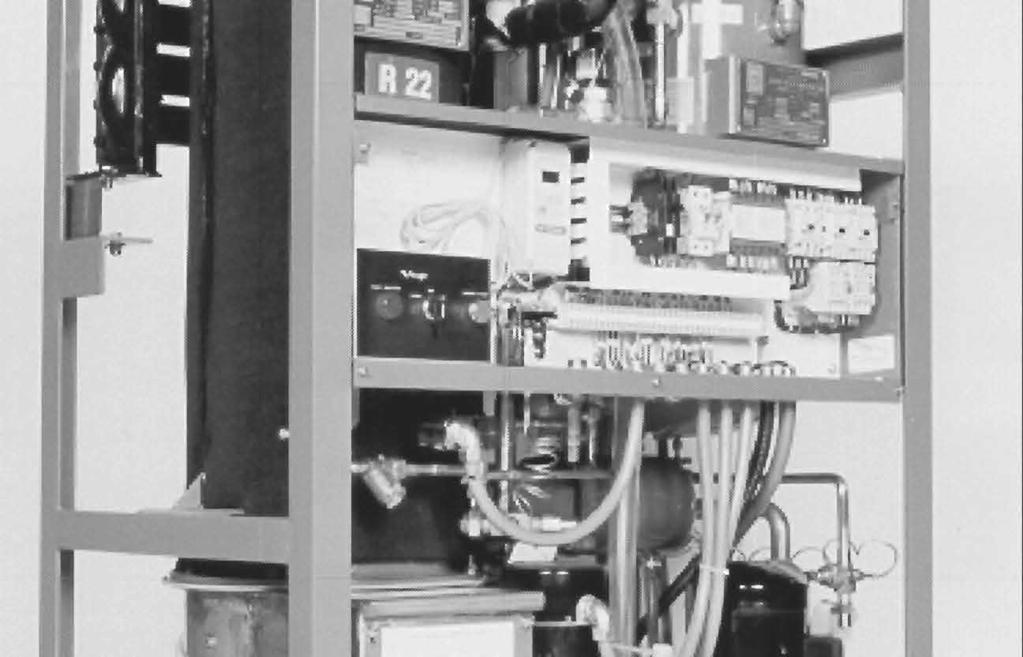
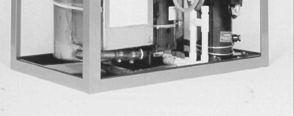
23 HES Series Service Manual 4-1 ELECTRICAL CONTROLS & THEIR FUNCTIONS 4. Electrical Controls & Their Functions FIGURE 4-1A Control Panel (Cover Removed) Note: Machines manufactured after May 1999 will use Allen-Bradley controls FIGURE 4-1B Control Panel with Hoffman Enclosure (Door Open) 5/24/11
24 4-2 HES Series Service Manual ELECTRICAL CONTROLS & THEIR FUNCTIONS Vogt Part # Reference Cutler-Hammer Allen-Bradley Description BC1 12A2117G09 SAME CRUSHED ICE BIN CONTROL (DUAL ICE ONLY) BC2 12A2117G09 SAME CYLINDER ICE BIN CONTROL C 12A7516E10 12A7516E26 COMPRESSOR CONTACTOR 12A7518E15 12A7518E30 COMPRESSOR AUX CONTACT CB1 12A7515E18 SAME PUMP / CUTTER MOTOR CIRCUIT BREAKER (10 AMP) CB2 12A7515E19 SAME * CONDENSER FAN MOTOR CIRCUIT BREAKER (15 AMP) CB3 & CB4 12A7515E20 (QTY 2) 12A7515E21 CONTROL CIRCUIT BREAKER (3 AMP) CPA N/A 12A7700P02 COPELAND PERFORMANCE ALERT CU 12A7530E11 12A7516E23 CUTTER MOTOR STARTER / CONTACTOR 12A7508H A7538E01 CUTTER OVERLOAD HEATERS ( A) / OL RELAY (2-7 A) FPS1 12A2117E04 SAME FREEZER PRESSURE SWITCH (DUAL ICE ONLY) FPS2 12A2117E04 SAME FREEZER PRESSURE SWITCH FU1-FU3 N/A 12A7504E13 CONDENSER FAN MOTOR FUSES, 6A, 600V (400/460V MACH) FU10 & FU20 N/A 12A7504E14 CONTROL CIRCUIT FUSES, 7A, 600V (400/460V MACH) P 12A7530E11 12A7516E23 PUMP MOTOR STARTER / CONTACTOR 12A7508H A7538E01 PUMP OVERLOAD HEATERS ( AMPS) / OL RELAY (2-7 A) PB1 12A7500E45 12A7500E56 12A7500E75 HARVEST / START BUTTON CONTACT BLOCK (FOR ALLEN-BRADLEY ONLY) PLF N/A 12A7537S06 POWER LINE FILTER (CE MACHINES ONLY) PLC SAME 12A7536M01 PROGRAMMABLE CONTROLLER R 12A7517E18 12A7517E27 REVERSING RELAY (DUAL ICE ONLY) SS 12A7500E43 SAME 5 POSITION SELECTOR SWITCH (DUAL ICE) 12A7500E44 12A7500E61 12A7500E73 3 POSITION SELECTOR (SINGLE ICE) CONTACT BLOCK (FOR ALLEN-BRADLEY ONLY) TB N / A N / A TERMINAL BLOCK TEST N / A N / A TEST BLOCK (ON CUTLER-HAMMER - FACTORY USE ONLY) 1LT 12A7500E46 12A7500E65 FAULT INDICATOR LIGHT *Note: AIR COOLED ONLY TABLE 4-1 Control Panel Parts List 5/24/11
25 HES Series Service Manual 4-3 ELECTRICAL CONTROLS & THEIR FUNCTIONS Description of Control Panel Parts. *BC1 and BC2. Bin Controls. Ice bin thermostats for automatically stopping and starting the machine based on the ice level in the storage bin. BC1 (Crushed Ice). BC2 (Cylinder Ice). C. Compressor Motor Contactor. Provides power to the compressor motor. Energized during freezing and thawing. Normally closed contact provides power to the compressor crankcase heater when the machine is off. CB1. Pump / Cutter Motor Circuit Breaker (10 amps). Two pole magnetic circuit breaker used for short circuit protection in the cutter or pump motor circuit. If breaker trips, power is removed from control circuit, shutting machine down. CB2. Condenser Fan Motor Circuit Breaker (15 amps). Two-pole thermal magnetic circuit breaker used for short circuit protection in the condenser motor circuit. If breaker trips, power is removed from condenser only. Machine will eventually shut off on high discharge pressure. CB3 and CB4. Control Circuit Breaker (3 Amps). Current limiting thermal magnetic circuit breaker used as overload and short circuit protection for crankcase heater, PLC outputs and other control circuit components. CPA. Copeland PerformanceAlert. Device that monitors compressor current, phase and temperature and shuts off machine if a problem is detected. CU. Cutter Motor Starter. Cutler-Hammer: A three phase motor starter with adjustable bimetallic heater packs, wired for use with single-phase motor. Cutter Motor Overload (heater packs) Class 10 overloads rated Amps set at cutter motors FLA rating. Pull "Reset" button to test overload. Allen-Bradley: Motor starter made of 3-pole contactor and solid-state overload relay, wired for use with single-phase motor. Overload - Class 10 rated 2-7 Amps set at cutter motors FLA rating. Press "TEST" button to test overload. Can be configured to reset automatically ( A ) or manually ( M ). PLC controlled machines will have the overload reset in the automatic position. When an overload condition occurs, an auxiliary contact signals the PLC of a problem and shuts the machine off (PLC input light # 5 will be off when overload is tripped). Will automatically reset after an overloads cool. See Section 7, Motor Over Current Protection for details. *FPS1 and FPS2. Freezer Pressure Switches. For regulating the ice thickness by sensing the freezer pressure and initiating the thaw period. FPS1 (Crushed Ice). FPS2 (Cylinder Ice). FU10 & FU20. Transformer Primary Protection Fuses - 400/460V machines only. (7A, 600V, time delay fuses). Fuses used for transformer primary protection along with control circuit upstream of CB3/CB4. FU1, FU2 & FU3. Condenser Fan motor Fuses - 400/460V machines only. (6A, 600V, Time delay fuses). Fused used for short circuit protection in the condenser motor circuit. If fuse(s) blows, power is removed from condenser only. Machine will eventually shut off on high discharge pressure. 5/24/11
26 4-4 HES Series Service Manual ELECTRICAL CONTROLS & THEIR FUNCTIONS P. Pump Motor Starter. Cutler-Hammer: A three phase motor starter with adjustable bimetallic heater packs, wired for use on single phase. Pump Motor Overload (heater packs) Class 10 overloads rated Amps set at pump motors FLA rating. Pull "Reset" button to test overload. Allen-Bradley: Motor starter made of 3-pole contactor and solid-state overload relay, wired for use with single-phase motor. Overload - Class 10 rated 2-7 Amps set at pump motors FLA rating. Press "TEST" button to test overload. Can be configured to reset automatically ( A ) or manually ( M ). PLC controlled machines will have the overload reset in the automatic position. When an overload condition occurs, an auxiliary contact signals the PLC of a problem and shuts the machine off (PLC input light # 5 will be off when overload is tripped). Will automatically reset after an overloads cool. See Section 7, Motor Over Current Protection for details. PB1. Start/ Harvest button. For starting the machine in the ice-making mode. Momentary contact or initiating a harvest cycle if the machine is in the freeze mode. Can be used to bypass the built in 120 minute start-up mode delays as well as terminate a harvest cycle. PLC. Programmable Logic Controller. For monitoring, sequencing, and controlling various functions of the Tube-Ice operation. Also has a built in thaw timer for controlling the time of the thawing period. Thawing time is adjustable from 1 1/2 to 5 minutes. PLF. Power Line Filter. Used on CE approved machines only. Used to reduce amount of noise on incoming power lines. *R. Reversing Relay. Switches machine to crush ice by making or breaking various circuits concerning crushed ice production. Energized during crushed ice production only. SS. Selector Switch. Dual Ice machines Five positions switch for the purpose of selecting form five different machine modes. Clean / crushed / cylinder / Both (cyl & crushed) / off. Single Ice machines Three position switch for the purpose of selecting from three different machine modes, clean / Ice / off. 1LT. Fault indicator light (24VDC light) flashes a designated number of times. A non-auto restart fault occurs or a auto-restart fault occurs three consecutive times. *Note: Components used in dual ice type machines only. 5/24/11
27 HES Series Service Manual 4-5 Wiring And Electrical Connection. ELECTRICAL CONTROLS & THEIR FUNCTIONS Refer to TABLE 4-1 below to properly size wiring connections. A fused disconnect must be provided near the Tube-Ice machine. Connect 3-phase power to terminals L1, L2, L3 for operation of the Tube-Ice machine and its controls. If one leg of the 3 phase power is higher or lower ( Wild ), then it should be connected to terminal #L2. Connect the Ground wire to the Ground terminal provided. On dual voltage, 50 Hz machines, the 220V single phase should be connected to terminals L4 and L5. Note: When initially starting the machine, the scroll compressor must be phased properly. If the compressor is run backwards for an extended period of time, the compressor may be damaged. See Section 7, Compressor Motor Rotation for details. Air-cooled condenser should be wired to terminals 20,21,22 and 23 (see FIGURES 4-9, 4-10). 460V air cooled condensers should be wired to terminals B1, B2, B3, 22 & 23. FIGURE 4-2 Terminal Block Connections Standard Voltages: Water Cooled Air Cooled Model Voltage F.L.A. Min. Ampacity Max. Fuse F.L.A. Min. Ampacity Max. Fuse HES20 208/230, 3p, 60 hz , 3p, 60 hz , 3p, 50 hz , 3p, 50 hz HES30 HES40 208/230, 3p, 60 hz , 3p, 60 hz , 3p, 50 hz , 3p, 50 hz /230, 3p, 60 hz , 3p, 60 hz , 3p, 50 hz , 3p, 50 hz TABLE 4-2 Electrical Specifications 5/24/11
28 4-6 HES Series Service Manual ELECTRICAL CONTROLS & THEIR FUNCTIONS Electrical Specifications PLC (Programmable Logic Controller) Sequence Of Controller & Machine Operation NOTE: Part #12A7536M01. PLC must be pre-programmed for specific model. FIGURE 4-3 PLC Display (Fxo shown above) PLC Inputs PLC Outputs # Description # Description 0 Cylinder Ice Indicator 0 Machine Fault Indicator Light 1 Crushed Ice Indicator 1 "A" valve 2 Freezer Pressure Switch 2 Compressor 3 Start / Manual Harvest 3 Reversing Relay (Dual Ice only) 4 Clean Switch 4 Water Pump 5 Pump / Cutter Overload ( off when tripped) 5 Cutter / "D" valve / Suction Stop 6 High / Low Pressure safety ( off when tripped) 7 N/A TABLE 4-3 PLC Inputs & Outputs Explanation. The HES-Series Tube-Ice machine is controlled by a PLC (Programmable Logic Controller). The PLC controls the sequence of events and monitors the ice machine functions. The operational sequences of the HES-Series Tube-Ice machine can be described best as a series of eight different modes. Each mode identifies and defines a sequence of events that occur while in that mode and thereby cause it to move to the next mode. Only one mode is active at a time. Start-Up Mode. The start-up mode is a function, which prevents the premature automatic starting of the machine at the time of installation, after a power interruption, or after a safety trip. Its normal time period is two hours. The start-up mode may be bypassed at any time by pressing the Harvest/Start button to immediately advance to the standby mode.! CAUTION! If the power has been turned off to the machine, make sure the compressor crankcase is warm And there is no liquid refrigerant in with the oil before restarting the unit.! CAUTION! 5/24/11
29 HES Series Service Manual 4-7 ELECTRICAL CONTROLS & THEIR FUNCTIONS Standby Mode. The standby mode is a decision-making mode. It monitors the position of all the various switches in the control circuit and at the proper time decides which mode to advance to next. Freeze Mode (Freeze Cycle). The freeze mode is active during the normal ice making cycle. During this time, the circulating water pump and compressor are running and the A (liquid feed) solenoid valve and X solenoid valve compressor discharge (AC units only) is open. Harvest Mode (Thaw Cycle). The harvest mode is normally initiated at the termination of the freeze mode. At this time, the circulating water pump stops and the A (liquid feed) solenoid valve closes. After seven seconds, the D (thaw gas) solenoid valve opens, the SS (suction stop) solenoid valve closes, the cutter motor starts and the thaw timer is activated. The harvest mode is terminated by the thaw (harvest) timer at which time the machine will begin another freeze cycle. The harvest mode can also be terminated manually by pushing in the Harvest/Start button. NOTE: If the Selector Switch switch is in the Off position or the bin control is satisfied the machine will advance to the partial pumpdown mode before shutting off (standby mode). Partial Pumpdown Mode. The partial pumpdown mode precedes the normal off or standby mode. Its purpose is to transfer a portion of the liquid from the suction accumulator and freezer into the receiver prior to shutdown of the machine (standby mode). This will discourage any migration of liquid refrigerant to the compressor during the off or standby mode. It is also intended to prevent any liquid refrigerant slugging to the compressor when the machine restarts in a freeze mode. When partial pumpdown is initiated, the A (liquid feed) solenoid valve is closed and the water pump and compressor run for a set time. After this set time the compressor stops and the machine is in the standby mode. Model HES-20 HES-30 HES-40 Time 7 minutes 5 minutes 3 minutes TABLE 4-4 Partial Pumpdown Time NOTE: The PLC uses the cylinder ice pressure switch (FPS2) as a partial pumpdown safety. Do not remove this pressure switch from the machine. Total Pumpdown Mode. The function of the total pumpdown mode is to transfer all of the liquid refrigerant from the freezer (evaporator) into the receiver. Total pumpdown is initiated as the first phase of and prior to entering the Clean mode. Its main purpose is to clear the freezer of liquid refrigerant and prevent possible refrigerant migration to the compressor while running the Clean cycle. It can also be used to check the units total refrigerant charge, isolate the refrigerant in the receiver while making repairs, or prepare the machine for disconnecting and moving. To restart the machine after a total pumpdown, put the Selector Switch switch in the Ice position and press the Harvest/Start button. At this time the A (liquid feed) solenoid valve will open for two minutes, allowing refrigerant to feed into the freezer before the machine starts into a freeze cycle. 5/24/11
30 4-8 HES Series Service Manual 5/24/11 ELECTRICAL CONTROLS & THEIR FUNCTIONS Clean Mode. The Clean mode is considered to be maintenance or servicing function of the machine. During this mode only the water pump will run. The first phase of the Clean mode is a total pumpdown.! CAUTION! Do not attempt to bypass the total pumpdown phase of the Clean mode. If a clean cycle is performed without first completing a total pumpdown, the warm water being circulated through the freezer tubes can force refrigerant to migrate to the suction accumulator and compressor which can cause compressor damage when returning to the freeze mode.! CAUTION! After the total pumpdown, the water pump can be stopped by simply moving the Selector Switch from the Clean to the Off position. To restart the water pump, move the Selector Switch back to the Clean position and press the Harvest/Start button. (Note: If the freezer and compressor suction pressure have come up enough to open the freezer pressure switch FPS2 and close low pressure safety switch 4PS, the compressor will come on and pump down the freezer again.) Ice machine cleaning solution can be circulated though the tubes to accomplish the cleaning procedure. If the water pump is left to run in the clean mode for more than two hours, the PLC will shut the machine off. The clean mode can be resumed by pushing the Harvest/Start button. NOTE: Running in Clean mode for extended period of time can cause excessive pressure to build up in the freezer. At the termination of the clean mode, the machine can be returned to ice making mode by putting the Selector Switch in the Ice position and pressing the Harvest/Start button.. At this time the A (liquid feed) solenoid valve will open for two minutes, allowing refrigerant to feed into the freezer before the machine starts into a freeze cycle. Fault Mode. The HES Series ( S for Smart) is equipped with a PLC (programmable logic controller) that controls all aspects of the operation. One of the functions of the PLC is to shut down the machine when a problem arises and send a signal to the fault indicator light located on the far-left side of the electrical panel. The red light is visible through the opening in the front casing and will blink when a problem has caused the machine to shut down (See FIGURE 4-2). NOTE: The Fault Light will flash the designated number of times ONLY if the fault is a not a autorestart fault or a auto-restart fault that has occurred three consecutive times. For your reference, TABLE-4-3 contains a list of fault codes. # Description Restart Off Delay 1 High / Low Press - Freeze No N/A 2 High / Low Press - Harvest No N/A 3 High / Low Press - Partial Pumpdown No N/A 4 High / Low Press - Total Pumpdown No N/A 5 Short Cycle Yes 2 hrs 6 Long Cycle No N/A 7 Pump Motor Overload Yes 30 min 8 Cutter Motor Overload Yes 30 min N/A Power Failure Yes 2 hrs NOTE: The machine may be off on a fault and not flashing an error code if the fault is an auto-restart fault and it is not the third consecutive occurrence of this fault. TABLE 4-5 PLC Fault Codes
31 HES Series Service Manual 4-9 ELECTRICAL CONTROLS & THEIR FUNCTIONS Copeland Performance Alert (CPA). This device is used to monitor the compressor discharge temperature, compressor current and phase, as well as control voltage to the compressor contactor. If a problem is detected, the compressor will shut off. The fault light on the CPA will flash a certain number of times to indicate the fault that occurred. See table below. NOTE: When this occurs, the ice machine will continue to run but the compressor will not be on. The ice machine will eventually shut off on a Long Cycle Fault. Some faults, referred to as lockout faults, will require cycling power to the Performance Alert to reset. This can be done by switching CB1 to the off position for 5 seconds, then back on. NOTE: If ice machine has a High/Low pressure fault, the Performance Alert can detect low control voltage at the compressor contactor and flash 9 times. This will clear when the machine is re-start. FIGURE 4-4 Copeland Performance Alert Wiring Alert Codes System Conditions Description 1 High Discharge Temperature Discharge Temperature above set point (default 230 Deg F) adjustable 170 to Lock Rotor 4 Consecutive Compressor trips after run time of 1 to 15 seconds indicating compressor won't start 6 Missing Phase Demand signal is present but current is missing in one phase 7 Reverse Phase (Scroll only) Demand signal is present but current is not detected in the correct sequence 8 Welded Contactor No demand signal but current has been detected in one or both phases 9 Low Voltage Control voltage dips below 85V for 110V or 170V for 220V 11 DLT Sensor Failure Discharge Temperature Sensor short or open circuit Note: Faults 1, 4, 6, 7, 9 will shut off compressor with a off time of 20 minutes (adjustable from 10 to 40 minutes). If fault 1, 4, 6 or 7 occurs ("LOCKOUT"), fault must be manually reset by cycling power to the Performance Alert. Lockout Configuration Code Minimum Maximum Default 1 High Discharge Temp Locked Rotor Missing Phase Reverse Phase TABLE 4-6 Copeland Performance Alert Codes 5/24/11
32 4-10 HES Series Service Manual ELECTRICAL CONTROLS & THEIR FUNCTIONS 1 Flash - High / Low Pressure Fault during Freeze 2 Flashes - High / Low Pressure Fault during Harvest Press Harvest / Start Button twice to restart machine 2 Minute Freeze Harvest Mode Freeze Mode 3 Flashes - High / Low Pressure Fault during Partial Pumpdown 4 Flashes - High / Low Pressure Fault during Total Pumpdown 5 Flashes - Short Cycle Faults (3 Consecutive) 6 Flashes - Long Cycle Fault 7 Flashes - Water Pump Motor Overload Fault (3 Consecutive) Press Harvest / Start Button twice to restart machine Run water pump for 30 Minutes 8 Flashes - Cutter Motor Overload Fault (3 Consecutive) 2 Minute Harvest Freeze Freeze Mode Mode Note: While in the Fault Mode, if Harvest / Start Button is pressed twice and the machine does not start, one of the following is true: * Bin control is not calling for ice or Selector switch is in the off position (PLC input lights 0 & 1 are off ) * The high / low pressure switch is tripped (PLC input light 6 is off ) * The Cutter or Pump overload is tripped (PLC input light 5 is off ) FIGURE 4-5 Machine Fault Startup Sequence FIGURE 4-6 Fault Indicator / Selector Switch Location 5/24/11
33 HES Series Service Manual 4-11 ELECTRICAL CONTROLS & THEIR FUNCTIONS NOTE: USE COPPER CONDUCTORS RATED 60 C OR HIGHER Machines w/copeland Performance Alert * Standard on machines manufactured after January /24/11 FIGURE 4-7 Dual Ice Type
34 4-12 HES Series Service Manual ELECTRICAL CONTROLS & THEIR FUNCTIONS NOTE: USE COPPER CONDUCTORS RATED 60 C OR HIGHER Machines w/copeland Performance Alert * Standard on machines manufactured after January 2010 FIGURE 4-8 Single Ice Type 5/24/11
35 HES Series Service Manual 4-13 ELECTRICAL CONTROLS & THEIR FUNCTIONS NOTE: USE COPPER CONDUCTORS RATED 60 C OR HIGHER Machines w/copeland Performance Alert * Standard on machines manufactured after January /24/11 FIGURE 4-9 Single Ice (Dual Voltage) 50 HZ, 400V compressor, 200V controls
36 4-14 HES Series Service Manual ELECTRICAL CONTROLS & THEIR FUNCTIONS NOTE: USE COPPER CONDUCTORS RATED 60 C OR HIGHER 5/24/11 FIGURE 4-10 Single Ice (400V / 460V) Machines w/copeland Performance Alert * Standard on machines manufactured after January 2010
37 HES Series Service Manual 4-15 Wiring Connections to Air-Cooled Condenser. ELECTRICAL CONTROLS & THEIR FUNCTIONS FIGURE 4-11 Wiring For BOHN DVT005 with Cold Weather Valve and Single Fan, 50/50 Condenser Split 5/24/11
38 4-16 HES Series Service Manual ELECTRICAL CONTROLS & THEIR FUNCTIONS FIGURE 4-12 Wiring For BOHN DVT008 with Cold Weather Valve and Single Fan, 50/25/25 Condenser Split 5/24/11
39 HES Series Service Manual 4-17 ELECTRICAL CONTROLS & THEIR FUNCTIONS FIGURE 4-13 Wiring For BOHN DVT012 /DVT016 with Cold Weather Valve and Two Fan, 50/50 Condenser Split 5/24/11
40 5/24/11 Blank page
41
42
43
44
45
46
47
48
49
50
51

52
53
54
55
56
57
58
59
60
61
62
63
64
65
66
67
68
69
70
71
72
73
74
75
76 7-16 SERVICE OPERATIONS HES Series Service Manual High/Low Pressure Safety Switch. The high-low pressure switch (4PS) (FIGURE 7-14) is a twopole dual function switch. Located in the machine outside the control panel, it protects the machine from possible damage due to abnormal pressure during operation.! CAUTION! When this switch causes the machine to stop, the cause should be identified and corrected before resuming normal operation. See Fault Identity, Section 6, Table 6-2.! CAUTION! The LOW pressure cut-in should be set at 40 psig (R-22), 50 psig (R-404A) and the cutout set at 20 psig (R-22), 30 psig (R-404A). After tripping at the cutout setting, the switch will reset automatically when the pressure rises to the cut-in setting. The HIGH-pressure cutout should be set at 300 psig (R-22) & 350 psig (R-404A). After tripping, reset the switch manually. Note: After a high-pressure trip, the discharge pressure must drop 50 psig before the switch can be reset. DIFFERENTIAL ADJUSTING SCREW (CCW RAISES SETTING) RANGE ADJUSTING SCREW (CW RAISES SETTING) HIGH PRESSURE ADJUSTMENT SCREW (DIFFERENTIAL FACTORY SET AT 55 PSIG) Vogt Part #: 12A2117D02 FIGURE 7-14 High /Low Pressure Safety Switch NOTE: High-low pressure switch contains both high and low voltage circuits. Line numbers 12 and X6 supply a low voltage signal to the PLC. Line numbers Y2 and 18-supply power to the compressor contactor coil. If it becomes necessary to install a new high/low pressure switch, the following procedure is recommended for its adjustment: Turn the adjusting screws clockwise to raise the pressure setting. Turn counter-clockwise to lower the setting. Adjust the switch to the indicated pressure settings and test with an accurate gage to be sure the switch functions properly before installation. 5/26/11
77 HES Series Service Manual SERVICE OPERATIONS 7-17 Head Pressure. The head pressure should be maintained at degf condensing during the freeze cycle. The compressor discharge pressure can be checked at the test connection on the highlow pressure switch. CUT IN ADJUSTING SCREW (CW LOWERS SETTING) CUT IN ADJUSTING SCREW (CW RAISES SETTING) Vogt Part #: 12A2117F08 FIGURE 7-15 Condenser Fan Switch Air-Cooled Units. The condenser fan switch (FIGURE 7-15) (CPS) has a two-pole switch that is used to regulate the head pressure. This is an adjustable pressure switch located on the right-hand side of the machine directly controls the operation of the condenser fan motor(s). The switch is set to cycle the fan motor(s) On at 210 psig (R-22), 250 psi (R-404A) and Off at 190 psig (R-22), 230 psi (R-404A). NOTE: Older HE and R12 machines used a single pole fan switch and a fan contactor to control the fan motor (s). The HE S-series machine no longer uses a fan contactor. Cleaning Air-Cooled Condenser. Visual inspection will indicate if dirt is accumulating and clogging the fin face of the condenser. A vacuum cleaner, compressor air or a brush may be used to remove an accumulation of dirt from the fin section of the condenser. Solenoid Valve Thermostats Condenser Description Valve Valve Rebuild Kit Replacement Coil Fan Solenoid DVT005 5/8 N.O. 12A4200A A4199V42 12A2105C04 Penn A19 Penn A319 DVT008 7/8 N.O. 12A4200A A4199V44 12A2105C04 DVT012 DVT /8 N.O. 12A4200A A4200A A4199V45 12A4199V55 12A2105C04 12A2105C25 Note: Sporlan Solenoid Valves Sporlan Solenoid valve OE34S290 (12A4200A0902) discontinued in Aug 2006 TABLE 7-6 Cold Weather Kit Replacement Parts 5/26/11
78 7-18 SERVICE OPERATIONS HES Series Service Manual Ice Machine Model HE20 HE30 HE40 DVT005 DVT008 DVT012 Recommended Condenser (DVT008) (DVT012) (DVT016) Note: For continuous operation at ambient above 90 F, use larger condenser shown in parenthesis Total Heat Rejection: (15 F TD) BTU/hr at 60 Hz. BTU/hr at 50 Hz. 35,700 32,800 58,800 54, , ,100 Fans: Number HP, Each Total, CFM 1 1/3 (1/2) 5,050 (6,450) 1 (2) 1/2 6,450 (12,400) 2 1/2 12,400 (12,900) Full Load Amps: Weight, lbs.: Condenser dimensions, inches: Recommended Line Sizes, OD: Connections at Condenser: 1 ph., 208/230V, 60 Hz 3 ph., 208/230V, 60 Hz 3 ph., 460V, 60 Hz 1 ph., 200/220V, 50 Hz 3 ph., 200/220V, 50 Hz 3 ph., 400V, 50 Hz Net Shipping Operating (maximum flooded) A (Width) B (Length) C (Height) D (Leg centerline) E (Leg centerline) F (Clearance below) Liquid (All lengths and orientations) Discharge Gas Vertical Up, All lengths Horizontal Or Down, < 75 ft. Horizontal Or Down, > 75 ft. Liquid (ODC) Discharge Gas (ODC) 3.4 (3.9) N/A 1.3 (1.3) 3.4 (3.9) N/A 1.3 (1.3) 180 (260) 320 (390) 195 (285) (49.75 ) 30 (40 ) (40 ) /2 5/8 5/8 7/8 5/8 (7/8 ) 7/8 (1 1/8 ) 3.9 (7.8) N/A 1.3 (2.6) 3.9 (7.8) N/A 1.3 (2.6) 260 (470) 390 (520) 285 (500) (69.75 ) 40 (60 ) (60 ) /8 7/8 7/8 1-1/8 7/8 1 1/8 7.8 (7.8) N/A 2.6 (2.6) 7.8 (7.8) N/A 2.6 (2.6) 470 (530) 520 (680) 500 (560) /8 1-1/8 1-1/8 1-3/8 7/8 1-1/8 (1-3/8 ) Connections at Machine: Liquid & Discharge Gas (ODC) 1-1/8 1-1/8 1-1/8 TABLE 7-7 Air-Cooled Condenser Data 5/26/11 FIGURE 7-16 Condenser Dimensions
79 HES Series Service Manual 7-19 SERVICE OPERATIONS FIGURE 7-17 Wiring For BOHN DVT012 /DVT016 with Cold Weather Valve and Two Fan, 50/50 Condenser Split Water-Cooled Units. A water-regulating valve (FIGURE 7-18) located in the condenser water inlet line is used to control the water flow through the condenser. This valve should be adjusted to maintain a head pressure of psig. Increasing the water flow lowers the head pressure and decreasing the water flow raises the head pressure. FIGURE 7-18 Water Regulating Valve Machine Size Vogt Part # HES-20 & HES-30 3/4 12A4200E0605 HES A4200E0802 * HES-20 & HES30 1/2 12A4200E0402 * HES A4200E0801 TABLE 7-8 Water Regulating Valves Note: * High water pressure regulating valves (above 90 psig) 5/26/11
80 7-20 SERVICE OPERATIONS HES Series Service Manual Water Cooled Condenser Service. High head pressure due to fouled condenser. Eliminate other possible causes: Non-condensables Faulty gauge Refrigerant restriction Water regulating valve High inlet water temperature Insufficient water supply Example Liquid return (RCVR) Psig = 200 = 102 F (SAT) Water outlet temperature = 95 F Difference = 7 F If difference is more than 10 F, cleaning is indicated. For cleaning procedure see, Water Cooled Condenser Cleaning, Section 5. Compressor Crankcase Heater. When electrical power is supplied to terminals L1, L2 & L3 of the control panel, the crankcase heater is energized when the compressor is not operating. The purpose of the crankcase heater is to keep the compressor warm to prevent the migration of refrigerant to the compressor while the compressor is not running. Machine Size Vogt Part # HES-20/HES-30/HES watts (at 230V) 12A 7509E13 TABLE 7-9 Compressor Crankcase Heaters! CAUTION! In case of a power interruption, or crankcase heater failure, be sure the compressor crankcase is warm prior to restarting the machine manually! CAUTION! Compressor Motor Rotation. Scroll compressors must be phased properly at startup. Connect pressure gages to the high and low side of the compressor at the High / Low Pressure safety switch. Start machine by putting "Selector Switch" in the "Ice" position and pressing "Start / Harvest" button. The compressor discharge pressure should start to rise as the suction pressure drops. Within 30 seconds, the discharge pressure should be approximately psig. If the discharge pressure does not rise, and the suction pressure does not drop, the compressor is running backwards. Shut machine off power to the machine at the main disconnect and reverse wires labeled L1 and L3 in the compressor's electrical junction box. 5/26/11
81
82
83
84
85

86
87
88
89
90
91
92
93
94 5/24/11 Blank page
95
96 5/24/11 Blank page
97
98 9-2 TABLES & CHARTS HES Series Service Manual TEMPERATURE - PRESSURE CHART FOR COMMON REFRIGERANTS DegF R-12 R-22 R-502 R-134a MP-39 R-404a R-402a DegF R-12 R-22 R-502 R-134a MP-39 R-404a R-402a TABLE 9-3 All pressures are in lbs/in 2 gage (psig). 5/25/11
99
100 5/24/11 Blank page
101
102 5/24/11 Blank page
103 HES Series Service Manual 11-1 INDEX 11. Index A Accumulator , 3-3, 7-2 Adapter Plate , 7-11 Adjustable blowdown Automatic blowdown Air-cooled condenser data Air-cooled condenser: Cold weather kit parts Data Dimensions Wiring , 7-19 Allen Bradley Pressure Switch (FPS) Assembly Drwgs , 7-2 Auto-restart Fault "A" Valve (#20) , 3-3, 7-1, 7-14 B Bearing, Cutter , 7-11 Bill of Lading Bin, Ice Storage Bin, Thermostat Adjustments Bin, Thermostat (Dual Ice type) Bin, Thermostat Installation Bin, Thermostat (Single Ice type) Blowdown, Adjustable Blowdown, Automatic Burnout, Compressor C Capacity, Calculating Capacity, Ice Table Checklist, Daily Checklist, Preventive Maintenance Check Valve , 3-3 Chemical Cleaning Chute Assembly , 7-8, 7-9 Circuit Breaker, Cutter/Pump , 4-2, 7-24 Circuit Breaker, Control Circuit , 4-2, 7-24 Circulating Water Pump Motor , 7-6 Cleaning Procedure Clean Mode Clean/Off/ Ice Selector Switch , 7-27 Compressor , 3-3, 7-1, 7-2, 7-21 Compressor Burnout Compressor, Contactor , 4-2 Compressor Crankcase Heater Compressor Lubrication , 7-21 Compressor, Motor Burnout Compressor, Motor Contactor , 4-2 Compressor, Motor Overload Protection Condenser , 3-3, 7-17, 7-18 Condenser, Air-cooled Cleaning Condenser, Air-cooled Heat Rejection Condenser Fan Switch Condenser, Pressure Switch (CPS) Condenser, Water Cooled Maintenance - 5-6, 5-7, 7-20 Control, Panel Control, Panel Parts , 4-2 Controller (PLC) , 4-5 Crankcase Heater Crushed Ice Preferred Cutter, Assembly , 7-9, 7-10, 7-11 Cutter, Bearing , 7-8, 7-9, 7-11 Cutter, Bearing Support , 7-9, 7-11 Cutter, Disc Assembly , 7-11 Cutter, Drive Parts Cutter, Gear Reducer , 7-7, 7-9, 7-10 Cutter, Motor , 7-9 Cutter, Over Current Protection Cutter, Short Circuit Protection Cutter, Parts , 7-11 Cutter, Water Tank Parts Cylinder to Crushed Conversion D "D" Valve (Thawing Gas #18) , 3-3, 7-14 Daily Checklist Discharge, Rota-lock , 7-13 Divider, Bin Defrost Pressure Switch (DPS) Draining Condenser Drip pan, maintenance Drive gear , 7-10 E Electrical Connection Electrical, Controls Electrical, Wiring Diagrams , 4-12, 4-13, 4-14 Energy Saving Expansion Valve , 7-13 F Fault Identity Fault Indicator Light Fault Mode Fault Startup Sequence FIGURE 3-1 (Air Cooled Piping Diagram) FIGURE 3-2 (Water Cooled Piping Diagram) FIGURE 3-3 (Bin Sensor Installation) FIGURE 4-1A & 4-1B (Control Panel) FIGURE 4-2 (Wiring & Electrical Connections) FIGURE 4-3 (PLC Display) FIGURE 4-4 (Copeland PerformanceAlert Wiring) FIGURE 4-5 (Fault Startup Sequence) FIGURE 4-6 (Fault Indicator Location) FIGURE 4-7 (Dual Ice, 200/ V Wiring) FIGURE 4-8 (Single Ice, 200/ V Wiring) FIGURE 4-9 (Dual Voltage, 200/400V, Wiring) /24/11
104 11-2 HES Series Service Manual INDEX FIGURE 4-10 (Single Ice, 400/460V, Wiring) FIGURE 4-11 (AC Condenser Wiring - Single Fan) FIGURE 4-12 (AC Condenser Wiring - Single Fan) FIGURE 4-13 (AC Condenser Wiring - Dual Fan) FIGURE 5-1 (Water Dist s, Replacement Gasket) FIGURE 5-2 (Scroll Compressor) FIGURE 6-1 (Machine Fault Indicator Light) FIGURE 6-2 (Fault Startup Sequence) FIGURE 6-3 (PLC) FIGURE 7-1A (Machine Layout - Front View) FIGURE 7-1B (Machine Layout - Side View) FIGURE 7-1C (Machine Layout - Rear View - WC) FIGURE 7-1D (Machine Layout - Rear View - AC) FIGURE 7-2 (Automatic Blowdown - Harvest) FIGURE 7-3 (Float Valve - Makeup Water) FIGURE 7-4 (Circulating Water Pump) FIGURE 7-5 (Freezer Cover Gasket) FIGURE 7-6 (Cutter-Water Tank Assembly) FIGURE 7-7 (Ice Discharge Arrangement) FIGURE 7-8 (Cutter-Water Tank Parts) FIGURE 7-9 (Cutter Drive Parts) FIGURE 7-10 (Cutter Parts) FIGURE 7-11 (Thermal Expansion Valve) FIGURE 7-12 (Solenoid Valve) FIGURE 7-13 (Freezer Pressure Switch) FIGURE 7-14 (High/Low Pressure Switch) FIGURE 7-15 (Condenser Fan Switch) FIGURE 7-16 (Condenser Dimensions) FIGURE 7-17 (Condenser Wiring) FIGURE 7-18 (Water Regulating Valve) FIGURE 7-19 (Scroll Compressor) FIGURE 7-20 (Suction Rota-lock Valve) FIGURE 7-21 (Discharge Rota-lock Valve) FIGURE 7-22 (Short Circuit Protection) FIGURE 7-23 (Motor Overloads) FIGURE 7-24 (Ice Bin Control) FIGURE 7-25 (Bin Thermostat Mounting) FIGURE 7-26 (Thawing Timer) FIGURE 7-27 (Selector Switch) FIGURE 7-28 (Cyl to Cru Terminal Block Jumper) FIGURE 7-29 (Freezer Pressure Switch) Filter/Drier , 3-3, 7-1, 7-2 Float Valve (water) Freeze Mode Freezer , 3-3, 7-1, 7-2 Freezer, Press. Switches (FPS1 & 2) , 7-31 G Gear Reducer , 7-9, 7-10 H Harvest Mode HE Model Structure Head Pressure Heater, Crankcase High-low Pressure Switch History, Tube-Ice Hub, Cutter Drive Gear I Ice Capacity Table Ice Bin Capacity Ice Bin Thermostat , 3-5 Ice, Chute Assembly , 7-7, 7-8 Ice, Deflector Door , 7-9, 7-11 Ice, Discharge , 7-8 Ice, Discharge Chute , 7-9 Ice, Selector Switch , 4-2, 7-28 Ice, Storage Important Safety Notice Index Inspection, First Arrival Introduction J, K L Leak Detector, Halogen Low Pressure Safety Switch Lubrication, Compressor Lubrication, Cutter Gear Reducer M Machine Room Make-Up Water Maintenance Maintenance Program , 5-10 Major Fault Manual Harvest / Start Push Button , 4-2 Mechanical Cleaning (WC Cond ) Metric Conversion Model Number Structure Moisture N NEMA Nomenclature, Piping Schematic Non-Condensable Gases Normal Operating Vitals Note To Manager Number Structure, HE O Oil Separator Operation Vitals Overload, Cutter & Pump P Partial Pumpdown Mode Performance Alert (Copeland) Performance Alert Wiring Pin, Stainless Steel , 7-11 Piping Schematic, Air-cooled Piping Schematic, Water cooled Piping Schematic, Nomenclature PLC Display , 4-6 5/24/11
105 HES-Series Service Manual 11-3 INDEX PLC Explanation PLC Inputs & Outputs PLC Modes , 4-7, 4-8 Power Connection Preventive Maintenance , 5-10 Principle of Operation Programmable Controller (PLC) , 4-2, 4-6 Pump, Starter , 4-2 Pumpdown, Partial Pumpdown, Total Pump Overload , 4-4, 7-25 Q R R-404A Receipt of Machine Receiver ,3-3, 7-1, 7-2 Regulating Valve, Water Refrigerant, Charge Refrigerant, Leaks Refrigerant, Removal Reversing Relay , 4-4 Rota-lock Valve, Discharge Rota-lock Valve, Suction S Safety, Codes Safety, Symbols Safety, Valves , 7-1 Sanitizing Procedure Selector Switch (SS) , 4-4, 7-28 Servicing Operations Shipping Papers Single Ice Type Single to Dual Ice Conversion Solenoid Valves Special Precautions Stand-by Mode Start / Harvest Push Button (PB1) , 4-4 Start-Up Mode Start-Up Report Front Pg. Storage Strainer , 3-3, 7-1 Sump Area, Water Tank Superheat Switch Plate T Table 4-1 (Control Panel Parts List) Table 4-2 (Electrical Specifications) Table 4-3 (PLC Inputs & Outputs) Table 4-4 (PLC Partial Pumpdown Time) Table 4-5 (PLC Fault Codes) Table 4-6 (Performance Alert Codes) Table 5-1 (Freezer Cover, Gasket, Distributors) Table 5-2 (Condenser Replacement Gaskets) Table 6-1 (PLC Fault Codes) Table 6-2 (PLC Inputs and Outputs) Table 7-1 (Water Pump Replacement Parts) Table 7-2 (Water Distributors) Table 7-3 (TXV Part #'s) Table 7-4 (Superheat Settings) Table 7-5 (Solenoid Valve Parts) Table 7-6 (Kramer Cold Weather Kit Parts) Table 7-7 (Air Cooled Condenser Data) Table 7-8 (Water Regulating Valves) Table 7-9 (Compressor Crankcase Heaters) Table 7-10 (Compressor Info) Table 7-11 (Suction Rota-lock Valve) Table 7-12 (Discharge Rota-lock Valve) Table 7-13 (Overload Heater Pack Settings) Table 7-14 (Freezer Pressure Settings) Table 7-15 (Ice Weights / Cycle) Table 9-1 (Ice Capacity) Table 9-2 (Normal Operating Vitals) Table 9-3 (Temperature-Pressure Chart) Table 9-4 (English-Metric Conversion) Table 9-5 (Constants) Technical Service Bulletin(Water Quality) Temperature-Pressure Chart Thawing, Chamber , 3-3 Thawing, Mode Thawing, Timer Thermostat, Adjustments Thermostat, Bin Installation Timer, Thawing Total Pumpdown Mode Troubleshooting U V Vitals, Operation W Warranty (Basic Product) Rear Pg. Warranty Registration Front Pg. Water Conditioning Water Cooled Condenser , 3-3, 7-20 Water Distributor , 7-5 Water Pump , 3-3, 7-1, 7-4, 7-6 Water Regulating Valve Water Quality Water Tank , 3-3, 7-8, 7-9 Water Tank, Cover , 7-9 Water Tank, Maintenance Water Tank, Parts , 7-9 Wiring and Electrical Connection Wiring Schematic, (Dual Ice) Wiring Schematic, (Single Ice) Wiring Schematic, (Single Ice Dual Voltage) Wiring Schematic, (Single Ice, 400/460V) X "X" Valve ( #53 ) , 3-3, 7-14 Y, Z 5/24/11
106

107
Air Cooled Condensing Units - Technical Catalog. Featuring Bitzer TM Compressors 404A and 507 Refrigerants
 N SERIES Air Cooled Condensing Units - Technical Catalog Featuring Bitzer TM s 404A and 507 Refrigerants 4492 Hunt St - Pryor, OK 74361-918.825.7222 - Fax 800.264.5329 - www.century-refrigeration.com Standard
Air Cooled Condensing Units - Technical Catalog. Featuring Copeland TM Compressors 404A and 507 Refrigerants
 N SERIES Air Cooled Condensing Units - Technical Catalog Featuring Copeland TM s 0A and 507 Refrigerants 9 Hunt St - Pryor, OK 736-98.85.7 - Fax 800.6.539 - www.century-refrigeration.com Standard Features
EFFICIENT 13 SEER 3 PHASE AIR CONDITIONER ENVIRONMENTALLY SOUND R 410A REFRIGERANT. Nominal Btu/hr. Min. Circuit Ampacity 18.
 ENVIRONMENTALLY SOUND REFRIGERANT H4A3 Product Specifications EFFICIENT 13 SEER 3 PHASE AIR CONDITIONER ENVIRONMENTALLY SOUND R 410A REFRIGERANT 3 THRU 5 TONS SPLIT SYSTEM 208 / 230 Volt, 3 phase, 60 Hz
B. System Design and Performance Requirements
 15625 Water Chillers This document provides design standards only, and is not intended for use, in whole or in part, as a specification. Do not copy this information verbatim in specifications or in notes
PSP Series Water Purification Systems
 Operations and Maintenance Manual for PSP Series Water Purification Systems PSP-1000 PSP-1600 PSP-2700 Rev. 2 / 08/26/14 Compact Design, Self-Contained Water Processing Unit for Point-Of-Use or Point-Of-Entry
AMCOT COOLING TOWER CORPORATION LRC-H & LRC-LNS CROSS FLOW COOLING TOWER OPERATIONS AND MAINTAINENCE MANUAL
 AMCOT COOLING TOWER CORPORATION LRC-H & LRC-LNS CROSS FLOW COOLING TOWER 1. Preface OPERATIONS AND MAINTAINENCE MANUAL 1-800-444-8693 Operation and Maintenance Manual For Amcot LRC-H Cooling Tower & LRC-LNS
START-UP CHECKLIST. Date: Job Name: Customer Name: Address: City: State: Zip: Model Number: Serial Number: Qualified Start-up Technician:
 START-UP INSTRUCTION SERIES 20 J**YC/YD 90000 To 300000 BTU S SPLIT SYSTEM CONDENSING UNITS 7.5 To 25 TON START-UP CHECKLIST Date: _ Job Name: Customer Name: Address: City: State: Zip: Model Number: Serial
Series Sump and Sewage Systems
 Series 000 Sump and Sewage Systems file no: 0. date: may 17, 13 supersedes: 0. date: march 29, 13 Series 000 Sump Series 0 & 2 Armstrong offers a complete range of high performance, easily maintained Column
SECTION AUTOMATIC TRANSFER SWITCH
 SECTION 26 36 23 AUTOMATIC TRANSFER SWITCH PART 1: GENERAL 1.01 SCOPE A. Furnish all labor, materials, equipment and appurtenances, install and test electrically operated, automatic transfer switch (ATS)
Installation Instructions
 Installation Instructions AquaSnap 010-055 Chilled Water Storage Tank 50/60 Hz Part No: -900---001; -900---009; -900---010 CONTENTS INTRODUCTION.................................. 1 SAFETY CONSIDERATIONS......................
SUPERSTEAM USG LINE UNFIRED STEAM GENERATOR. Humidification. Sterilization. Pharmaceutical
 SUPERSTEAM USG LINE UNFIRED STEAM GENERATOR. Humidification. Sterilization. Pharmaceutical Basic USG Package Includes: ASME Code Constructed and National Board Registered Vessel Fiberglass Insulation 20
INSTALLATION MANUAL AND OPERATING INSTRUCTIONS
 INSTALLATION MANUAL AND OPERATING INSTRUCTIONS MD41-( ) Series GPS ANNUNCIATION CONTROL UNIT FOR ALLIED SIGNAL KLN 900 MD41-1924 14vdc Horizontal Mount MD41-1934 14vdc Vertical Mount (shown on page 11)
Imperial Series. Model IMP-425/525/625/825/1000AP IMD-425/525/625/825/1000AP IMP-1025/1200/1500/2000AP IMD-1025/1200/1500/2000AP
 Service Manual Imperial Series Model IMP-425/525/625/825/1000AP IMD-425/525/625/825/1000AP IMP-1025/1200/1500/2000AP IMD-1025/1200/1500/2000AP Contents of Service Manual 1. Safety Precautions ------------------------------------------------------------------
Fiberglass Cooling Towers
 Fiberglass Cooling Towers Available in sizes from 100 to 240 tons. FC Series 700 Fiberglass Cooling Tower Available in sizes from 170 to 240 tons. No other fiberglass cooling tower comes with as many high-quality
AIR CONDTIONERS XC16. ELITE Series R-410A - Two-Stage Compressor - SilentComfort Technology
 AIR CONDTIONERS XC16 ELITE Series R-410A - Two-Stage Compressor - SilentComfort Technology E N G I N E E R I N G D ATA Bulletin 210465 October 2009 Supersedes March 2009 SEER up to 17.20 2 to 5 Tons Cooling
INSTALLATION MANUAL AND OPERATING INSTRUCTIONS
 INSTALLATION MANUAL AND OPERATING INSTRUCTIONS MD41-( ) Series GPS ANNUNCIATION CONTROL UNIT FOR NORTHSTAR M3 GPS APPROACH MD41-828 28vdc Horizontal Mount MD41-838 28vdc Vertical Mount (shown on page 13)
REVERSE OSMOSIS SYSTEM INSTALLATION, OPERATION, AND MAINTENANCE MAUAL
 REVERSE OSMOSIS SYSTEM INSTALLATION, OPERATION, AND MAINTENANCE MAUAL Table of Contents REVERSE OSMOSIS SYSTEM...1 1. INTRODUCTION...1 2. SYSTEM INFORMATION...1 3. INSTALLATION...2 4. FEED WATER SPECIFICATIONS...3
Quick-Start Operating Guide Document No Process Gas Cooler Copyright 2010 Terra Universal Inc. All rights reserved. Revised October 2010
 Document No. 1800-56 Copyright 2010 Terra Universal Inc. All rights reserved. Revised October 2010 Terra Universal, Inc. TerraUniversal.com 800 S. Raymond Ave. Fullerton, CA 92831 TEL: (714) 578-6000 FAX:
4DHP MULTI-ZONE PRODUCT SPECIFICATIONS OUTDOOR UNITS INDOOR UNITS 4DHP MULTI-ZONE DWM WALL MOUNTED CEILING CASSETTE DUCTED UNIT
 DHP MULTI-ZONE PRODUCT SPECIFICATIONS UP TO SEER UP TO DUCTLESS HEAT PUMP SYSTEMS UNITS FORM NO. DHPMULTI-00 (0/07) DHP MULTI-ZONE 8K / 0K / 6K / 8K Mid Efficiency (- SEER) Matches with all indoor units
ASPT Series. Multi-Position, Multi-Speed, ECM-Based Air Handler with Internal TXV 1½ to 5 Tons. Contents. Product Features
 Series Multi-Position, Multi-Speed, ECM-Based Air Handler with Internal TXV ½ to Tons Contents Air Handler Nomenclature... Heater Kit Nomenclature... Product Specifications... Dimensions... Airflow Data...
AS950 ALL-WEATHER REFRIGERATED SAMPLER
 AS950 ALL-WEATHER REFRIGERATED SAMPLER Applications Wastewater Collection systems Industrial pretreatment Environmental monitoring Stormwater Sampling has never been this easy. Hach's AS950 sampler controller
SECTION SLUDGE HOLDING TANK DECANTER PUMP
 PART 1 GENERAL 1.01 SCOPE OF WORK A. The Contractor shall furnish and install all materials, labor and equipment to put into service the Sludge Holding Tank Decanter Pumping System in accordance with the
INSTALLATION INSTRUCTIONS
 INSTALLATION INSTRUCTIONS 2190 Dagenais Blvd.West Laval (Quebec) Canada H7L 5X9 Tel. : 514.337.4415 Fax : 514.337.4029 info@burcam.com see us at www.burcam.com VERSION Z MODELS 300500 SUMP PUMPS Your pump
TGG, TBG, TEG, TUG, 3.9 TBS, Gene-Link series
 Absorption Chillers TGG, TBG, TEG, TUG, 3.9 TBS, Gene-Link series Stable Chilled Water Outlet Temperature PID control is applied to maintain constant chilled water outlet temperature. When the cooling
PROflex* 60 Hz Reverse Osmosis Machines from 50 to 360 gpm
 Fact Sheet PROflex* 60 Hz Reverse Osmosis Machines from 50 to 60 gpm Flexible Design PROflex has 0 base configurations using 8 to 7 elements that allows user to choose various pumps and membrane element
RDI Systems. Scroll Series Refrigeration System. Air Cooled Indoor/Outdoor Scroll Condensing Units 3/4 thru 6 Hp Models
 RDI Systems Scroll Series Refrigeration System Air Cooled Indoor/Outdoor Scroll Condensing Units 3/4 thru 6 Hp Models PC Refrigeration Systems The RDI PC Refrigeration system includes an RDI condensing
Product Data. 38AUZ Air Cooled Condensing Unit Puronr (R---410A) Refrigerant 6to12.5NominalTons FEATURES/BENEFITS. Factory-installed options (FIOPs)
 Refrigerant 6to12.5NominalTons FEATURES/BENEFITS. Factory-installed options (FIOPs)") 38AUZ Air Cooled Condensing Unit Puronr (R---410A) Refrigerant 6to12.5NominalTons Product Data Carrier s air-cooled air conditioning split systems: S provide a logical solution for commercial needs S have
38AUZ Air Cooled Condensing Unit Puronr (R---410A) Refrigerant 6to12.5NominalTons Product Data Carrier s air-cooled air conditioning split systems: S provide a logical solution for commercial needs S have
SECTION PACKAGE BOOSTER PUMP STATIONS
 SECTION 331223 PACKAGE BOOSTER PUMP STATIONS Scope: The Contractor shall install a pump station at two locations to be determined by the Owner. These pump stations shall be designed to deliver flow to
R.O water vending machine (USER MANUAL)
") R.O water vending machine (USER MANUAL) (ATTENTION) Before the installation and operation of the system, check the manual carefully for the best system condition, CONTENTS 1. PRODUCT APPEARANCE & SPECIFICATION
R.O water vending machine (USER MANUAL) (ATTENTION) Before the installation and operation of the system, check the manual carefully for the best system condition, CONTENTS 1. PRODUCT APPEARANCE & SPECIFICATION
Gerber M Series Site Requirements
 Gerber M Series Site Requirements Preparing for the arrival of your new machine. P rior to the arrival of your Gerber M Series Cutting System there are certain things you can prepare to facilitate a quick
INSTALLATION MANUAL AND OPERATING INSTRUCTIONS
 INSTALLATION MANUAL AND OPERATING INSTRUCTIONS MD41-( ) Series GPS ANNUNCIATION CONTROL UNIT FOR II MORROW APOLLO 2001TSO / 2001GPS / 2101/ GX50 / GX60 MD41-728 28vdc Horizontal Mount MD41-738 28vdc Vertical
SECTION ROTARY SCREW WATER CHILLERS
 PART 1 - GENERAL 1.1 RELATED DOCUMENTS A. Drawings and general provisions of the Contract, including General and Supplementary Conditions and Specification Sections, apply to this Section. B. Related Sections:
MODELS PH PH PH
 WWW.BURCAM.COM 2190 Boul. Dagenais West TEL: 514.337.4415 LAVAL (QUEBEC) FAX: 514.337.4029 CANADA H7L 5X9 info@burcam.com Your pump has been carefully packaged at the factory to prevent damage during shipping.
MV Product Specifications
 MODULAR VARIABLE SPEED BLOWER CABINET 2, 3, 4, and 5 TONS FEATURES Variable Speed modular blower Supports two-stage outdoor units Dehumidification Speed: 80% Airflow Efficient low continuous fan selection:
AVPTC. Multi-Position, Variable-Speed, ECM-Based Air Handler with Internal TXV ComfortNet Compatible 1½ to 5 Tons. Contents.
 Multi-Position, Variable-Speed, ECM-Based Air Handler with Internal TXV ComfortNet Compatible 1½ to 5 Tons Contents Air Handler Nomenclature... 2 Heater Kit Nomenclature... 2 Product Specifications...
1. Vertical reciprocating conveyor, Hydraulic straddle VRC.
 PART 1: GENERAL 1.01 Section Includes: 1. Vertical reciprocating conveyor, Hydraulic straddle VRC. a. Machine, controller, platform, structural steel hoist frame. b. Wire mesh enclosure and gates. Related
INSTALLATION MANUAL AND OPERATING INSTRUCTIONS
 INSTALLATION MANUAL AND OPERATING INSTRUCTIONS MD41-( ) Series GPS Annunciation Control Unit for GARMIN GPS 400/500, GNC 420 and GNS 430/530 Series Navigation Management System MFG. P/N: MD41-1408A 28VDC
SECTION COOLING TOWER
 PART 1 GENERAL 1.1 SECTION INCLUDES A. Mechanical induced draft Cooling Tower B. Controls C. Ladder and handrails 1.2 REFERENCES SECTION 23 65 00 COOLING TOWER A. ANSI/AFBMA 9 - Load Rating and Fatigue
TF20 Tray Feeder. Instruction Manual. for JEDEC and IEC Standard Trays
 for JEDEC and IEC Standard Trays Instruction Manual 096-0243-003 Data I/O assumes no liability for errors, or for any incidental, consequential, indirect, or special damages, including, without limitation,
VPL-3200B Residential Vertical Platform Lift Technical Specifications
 Page 1 of 5 VPL-3200B Residential Vertical Platform Lift Technical Specifications MODEL NUMBER: VPL-3200B Series: Models VPL-3210B, VPL-3212B and VPL-3214B (DC-powered units) U.S. F.D.A. CLASSIFICATION:
CFFWA-20-1-U Chilled/Hot Water Universal Mount Fan Coil 2-Pipe Heat / Cool Fan Coil 60,000 BTUH
 CFFWA-20-1-U Chilled/Hot Water Universal Mount Fan Coil 2-Pipe Heat / Cool Fan Coil 60,000 BTUH Rev. 1.3 HVAC Guide Specifications Chilled and Hot Water Universal Mount Fan Coil 2-Pipe Nominal Size: 60,000
Product Data. 38AUZ / 38AUD 60 Hz Air Cooled Condensing Unit Puronr (R---410A) Refrigerant 6to20NominalTons FEATURES / BENEFITS
 Refrigerant 6to20NominalTons FEATURES / BENEFITS") Z / D 60 Hz Air Cooled Condensing Unit Puronr (R---410A) Refrigerant 6to20NominalTons Product Data FEATURES / BENEFITS Z07-14 shown C09227 the environmentally sound refrigerant Carrier s air-cooled air
Z / D 60 Hz Air Cooled Condensing Unit Puronr (R---410A) Refrigerant 6to20NominalTons Product Data FEATURES / BENEFITS Z07-14 shown C09227 the environmentally sound refrigerant Carrier s air-cooled air
INSTALLATION MANUAL AND OPERATING INSTRUCTIONS
 INSTALLATION MANUAL AND OPERATING INSTRUCTIONS MD41-( ) Series GPS Annunciation Control Unit for Garmin GNS 430/530 VHF Communication and Navigation Management System MD41-1469 28vdc Horizontal Mount MD41-1479
Product Specifications
 Product Specifications MODULAR ELECTRIC FURNACE 2, 3,4,and5TONS FEATURES S Modular Blower Cabinet, Air Conditioning or Heat Pump ready S Upflow, horizontal right or left applications S Downflow requires
FOUR FOLD DOORS-WITH SINGLE OVERHEAD MTD OPERATOR
 FOUR FOLD DOORS-WITH SINGLE OVERHEAD MTD OPERATOR Section 083713- Four Fold Doors- With Single Overhead Mounted Operator Part 1-General 1.1 Related Document: A. Drawing and general provisions of contract,
Large University Central Chiller Plant Design Considerations
 Carrier Engineering Newsletter Volume 5, Issue 3 Large University Central Chiller Plant Design Considerations Large campus chilled water plants have unique constraints and need careful evaluation for successful
INDUSTRIAL FILTRATION EQUIPMENT LWS Filter Series
 INDUSTRIAL FILTRATION EQUIPMENT LWS Filter Series (Single, Twin, Triple or Quadruple Demand Systems) 1 P age filtration equipment can be engineered to solve complex commercial and industrial water treatment
AQUAROBIC MINI-PLANT TM
 AQUAROBIC MINI-PLANT TM Process Description The Mini-Plant TM is a Sequential Batch Reactor (SBR) system, controlled by a factory set programmer that regulates aeration, settling, and pump functions. The
Chiller Optimiser Technical Specification
 Chiller Optimiser Technical Specification 1. System Description The Chiller Optimiser Millennium Series is a self contained solid state dedicated microprocessor system. It has been specifically designed
EPS 7000 and EPS 8000
 EPS 7000 and EPS 8000 Single and Parallel Operation 09/2015 www.schneider-electric.com Legal Information The Schneider Electric brand and any registered trademarks of Schneider Electric Industries SAS
DVPTC. Multi-Position, Variable-Speed, ECM-Based Air Handler with Internal TXV ComfortNet Compatible 2 to 5 Tons
 DVPTC Multi-Position, Variable-Speed, ECM-Based Air Handler with Internal TXV ComfortNet Compatible 2 to 5 Tons Contents Air Handler Nomenclature...2 Heater Kit Nomenclature...2 Product Specifications...3
INSTALLATION MANUAL AND OPERATING INSTRUCTIONS
 INSTALLATION MANUAL AND OPERATING INSTRUCTIONS MD41-( ) Series GPS Annunciation Control Unit for Garmin GNS/GTN Systems. MD41-1470 28vdc Horizontal Mount Mid-Continent Instruments and Avionics Manual Number
Maintenance Bypass Breaker Cabinet Series Configuration 5. Installation and Operation Manual
 Maintenance Bypass Breaker Cabinet 90881 Series Configuration 5 Installation and Operation Manual 03/13/2012 2 755-00084-C5 R03 Copyright 2012 C&C Power, Inc. All rights reserved. C&C Power, Inc. 395 Mission
SECTION ACTIVE VEHICLE BARRIERS
 SECTION 34 71 13.19 ACTIVE VEHICLE BARRIERS PART 1 GENERAL 1.1 REFERENCES The publications listed below form a part of this specification to the extent referenced. The publications are referred to within
BLOWER COILS. 1½ THRU 5 TONS SPLIT SYSTEM EBP / EBX / EBXX Series FEATURES EBP MODEL FEATURES EBX/EBXXMODELFEATURES
 BLOWER COILS 1½ THRU 5 TONS SPLIT SYSTEM EBP / EBX / EBXX Series FEATURES Representative photo only, some models may vary in appearance. Grooved copper tubing Lanced sine--wave aluminum fin Fully wettable
Attachment 1: RAE Corporation Technical Specification
 Attachment 1: RAE Corporation Technical Specification RAE Corporation Phone: 918-825-7222, ext. 105 Steve Corbin Quote# XXXX Qty Customer Tag Technical Systems Model Number 1 ACC-4 10A0-162-S General Scope
300828TWP INSTALLATION INSTRUCTIONS MODEL SUBMERSIBLE SUMP PUMP
 www.burcam.com 2190 Dagenais Blvd. West TEL : 514.337.4415 LAVAL (QUEBEC) FAX : 514.337.4029 CANADA H7L 5X9 info@burcam.com Your pump has been carefully packaged at the factory to prevent damage during
Installation and Operation Manual
 Installation and Operation Manual Maintenance Bypass Panel Model: SU2030KMBP Tripp Lite follows a policy of continuous improvement. Product specifications are subject to change without notice. 1111 West
PROJECT TITLE PROJECT NO.: CONTRACT TITLE UNIVERSITY OF CALIFORNIA, DAVIS CITY, CALIFORNIA
 PRE-START-UP/START-UP CHECKLIST CHILLED WATER SYSTEM NOTE: University s Representative must be notified and scheduled to witness test prior to any start up of equipment. A. Chilled Water Pumps 1. Submittal
Shutdown and Cooldown of SEE-THRU Nuclear Power Plant for Student Performance. MP-SEE-THRU-02 Rev. 004
 Student Operating Procedure Millstone Station Shutdown and Cooldown of SEE-THRU Nuclear Power Plant for Student Performance Approval Date: 10/4/2007 Effective Date: 10/4/2007 TABLE OF CONTENTS 1. PURPOSE...3
BLOWER COILS COMMERCIAL
 BLOWER COILS COMMERCIAL 2 THRU 5 TONS SPLIT SYSTEM EBP / EBX / EBXX Series FEATURES Representative photo only, some models may vary in appearance. Listed By Underwriters Laboratories Grooved copper tubing
MHWW-09-H-1 Chilled/Hot Water Hi-Wall Fan Coil. Heat / Cool Fan Coil 9,000 BTUH. Rev. 1.3
 MHWW-09-H-1 Chilled/Hot Water Hi-Wall Fan Coil Heat / Cool Fan Coil 9,000 BTUH Rev. 1.3 HVAC Guide Specifications Chilled and Hot Water Hi-Wall Fan Coil 2-Pipe Nominal Size: 9,000 BTUH Multiaqua Model
Global Water Instrumentation, Inc.
 Global Water Instrumentation, Inc. 151 Graham Road P. O. Box 9010 College Station, TX 77842-9010 T: 800-876-1172 Int l: (979) 690-5560, F: (979) 690-0440 E-mail : globalw@globalw.com WS750 Sampler 01-457
AK SERIES (50Hz) ROOM AIR CONDITIONER AKY9FBSSW AKY9UBSSW. Models :
 ROOM AIR CONDITIONER AKY9FBSSW AKY9UBSSW. Models :") ROOM AIR CONDITIONER AK SERIES (50Hz) Models : AKY9FBSSW AKY9UBSSW CONTENTS SPECIFICATIONS.......................... CIRCUIT DIAGRAM........................ MICROCOMPUTER CONTROL CIRCUIT...... DISASSEMBLY
ROOM AIR CONDITIONER AK SERIES (50Hz) Models : AKY9FBSSW AKY9UBSSW CONTENTS SPECIFICATIONS.......................... CIRCUIT DIAGRAM........................ MICROCOMPUTER CONTROL CIRCUIT...... DISASSEMBLY
UFL Micro Biogas CHPs
 UFL Micro Biogas CHPs The UFL Micro Biogas CHPs are based on the highly durable Petter industrial diesel engine. Low cost replacement parts are available worldwide. This range of micro biogas CHPs has
Operations Manual. For Research Use Only. PH: EM: WEB:
 Operations Manual For Research Use Only PH: 908-769-5555 EM: info@benchmarkscientific.com WEB: www.benchmarkscientific.com Thank you for choosing the BioClave Benchtop Sterilizer. Prior to operating this
SPIRIT. Water purifier. Complete User Manual
 SPIRIT Water purifier Complete User Manual Document No 822901692 Revision BB1522 Bluewater 2015 Contents INTRODUCTION...03 About this manual...03 Limited warranty...03 Environment information...03 Disposal...03
RT8725. Single-Phase BLDC Fan Driver IC. Features. General Description. Applications
 RT8725 Single-Phase BLDC Fan Driver IC General Description The RT8725 is a single-phase driver IC for fan motors. Rotation speed is controlled by input signal. The RT8725 provides several protection features
SECTION 16496A MTS MANUAL TRANSFER SWITCH (MANUAL CONTROL ONLY) Note to Spec Writer: { } Denotes EATON Feature reference number
 Note to Spec Writer: { } Denotes EATON Feature reference number") MTS MANUAL TRANSFER SWITCH (MANUAL CONTROL ONLY) Note to Spec Writer: { } Denotes EATON Feature reference number PART 1 GENERAL 01 02 03 04 SCOPE Furnish and install Manual Transfer Switches (MTS) and
MTS MANUAL TRANSFER SWITCH (MANUAL CONTROL ONLY) Note to Spec Writer: { } Denotes EATON Feature reference number PART 1 GENERAL 01 02 03 04 SCOPE Furnish and install Manual Transfer Switches (MTS) and
AUTOMATIC BALING PRESS MODEL: HRB-CENTURION 200HP; 13/9
 Harris Equipment PROPOSAL SPECIFICATION: 20061122-121313 AUTOMATIC BALING PRESS MODEL: HRB-CENTURION 200HP; 13/9 GENERAL LAYOUT DRAWING: APPLICATION: 3A-13873 (LH/RH); 3A-13874 (LH/LH) 3A-13875 (RH/LH);
MERIGAUGE MODEL 3900 OPERATING INSTRUCTIONS
 99 Washington Street Melrose, MA 02176 Phone 781-665-1400 Toll Free 1-800-517-8431 Visit us at www.testequipmentdepot.com MERIGAUGE MODEL 3900 OPERATING INSTRUCTIONS Meriam Instrument s MERIGAUGE Model
TECHNICAL SPECIFICATIONS DIVISION 16 - ELECTRICAL SECTION DETAIL SPECIFICATIONS FOR ELECTRICAL INSTALLATION
 PART 1 - GENERAL 1.01 SCOPE The work covered by this section shall include furnishing and/or installation of all electrical and instrumentation equipment and necessary wiring systems required to provide
Global Water Instrumentation, Inc.
 Global Water Instrumentation, Inc. 151 Graham Road P. O. Box 9010 College Station, TX 77842-9010 T: 800-876-1172 Int l: (979) 690-5560, F: (979) 690-0440 E-mail : globalw@globalw.com WS700 Sampler 01-455
TM Series Cooling Tower Specification
 1.0 Cooling Tower TM Series Cooling Tower Specification 1.1 General: Furnish and install factory-assembled, induced draft, counterflow cooling tower(s) with vertical air discharge conforming in all aspects
120 Series Refrigeration Systems
 120 Series Refrigeration Systems RDI Systems Air Cooled Indoor/Outdoor Condensing Units Hermetic / Scroll / Semi-Hermetic ½ thru 6 Hp s PC Refrigeration Systems The RDI PC Refrigeration system includes
B. ASHRAE 1991 HVAC Applications Handbook: Chapter 34--Testing, Adjusting and Balancing.
 PART 1 GENERAL 1.1 RELATED DOCUMENTS SECTION 230593 TESTING, ADJUSTING, AND BALANCING A. Drawings and general provisions of Contract, including General and Supplementary Conditions and Division 1 Specification
Table of Contents. Installation 2-10 Leveler legs... 2 Controller... 4 Dip-switch Configurations. 5 Wire Harness Installation.. 7
 Table of Contents Installation 2-10 Leveler legs... 2 Controller... 4 Dip-switch Configurations. 5 Wire Harness Installation.. 7 Operation 11-14 Program HOME Position... 12 Program/Reprogram AUTO Level
2. Water Pressure Booster Systems. 3. Duplex Pedestal Type Sump Pumps.
 PART 1: GENERAL 1.01 Purpose: A. The design guidelines contained herein includes the requirements for pumps utilized for plumbing systems at Texas State University. It is the intention of this document
HYDRAULIC DOCK LEVELER OWNERS MANUAL
 HYDRAULIC DOCK LEVELER OWNERS MANUAL 1 HYDRAULIC DOCK LEVELER OWNERS MANUAL 2 TABLE OF CONTENTS Table Of Contents.. Page 2 Koke Hydraulic Leveler Model Information... Page 3 Hydraulic Dock Leveler Installation
NEC 2017 Code Changes Chapter 1 - General
 NEC 2017 Code Changes Chapter 1 - General Changes from the 2014 code are highlighted in yellow. ARTICLE 110 - Requirements for Electrical Installations Part I. General 110.1 Scope. This article covers
An Integrated Solution for Commercial AC Chillers Using Variable Speed Scroll Compressors
 Purdue University Purdue e-pubs International Refrigeration and Air Conditioning Conference School of Mechanical Engineering 2016 An Integrated Solution for Commercial AC Chillers Using Variable Speed
PDM16 & PDM32 User Manual
 MoTeC PDM16 & PDM32 User Manual Contents Introduction... 3 Operation... 4 Configuration...4 PDM Manager Software...4 PC Connection...4 Configuration Concepts...4 Conditions...7 Switch Inputs...7 CAN Inputs...8
SECTION HEAT TRACING FOR PLUMBING PIPING
 SECTION 22 05 33 HEAT TRACING FOR PLUMBING PIPING PART 1 - GENERAL 1.1 DESCRIPTION SPEC WRITER NOTES: 1. Delete between //----// if not applicable to project. Also delete any other item or paragraph not
Precision Automatic Vacuum Control (PAVC+)
") USER GUIDE UGE105-1216 www.conairgroup.com Precision Automatic Vacuum Control (PAVC+) Corporate Office: 724.584.5500 l Instant Access 24/7 (Parts and Service): 800.458.1960 l Parts and Service: 814.437.6861
USER GUIDE UGE105-1216 www.conairgroup.com Precision Automatic Vacuum Control (PAVC+) Corporate Office: 724.584.5500 l Instant Access 24/7 (Parts and Service): 800.458.1960 l Parts and Service: 814.437.6861
High Temperature Vacuum Tube Furnace GSL Operational Manual
 High Temperature Vacuum Tube Furnace GSL-1100 Operational Manual MTI Corporation 860 South 19 th Street, Richmond, CA 94804, USA Tel: 510-525-3070 Fax: 510-525-4705 E-mail: info@mtixtl.com Web site: www.mtixtl.com
Instruction Manual HT 24 BM-D2400 Homogenizer
 Instruction Manual HT 24 BM-D2400 Homogenizer Foreword Thank you for purchasing a HT 24 Homogenizer. This manual contains instructions for the proper operation and care of this instrument. Please read
REVERSE OSMOSIS SYSTEM Wall Mount (Hinged) Design
 Design") REVERSE OSMOSIS SYSTEM Wall Mount (Hinged) Design INSTALLATION, OPERATION, AND MAINTENANCE MAUAL Table of Contents REVERSE OSMOSIS SYSTEM...1 1. INTRODUCTION...1 2. SYSTEM INFORMATION...1 3. INSTALLATION...2
REVERSE OSMOSIS SYSTEM Wall Mount (Hinged) Design INSTALLATION, OPERATION, AND MAINTENANCE MAUAL Table of Contents REVERSE OSMOSIS SYSTEM...1 1. INTRODUCTION...1 2. SYSTEM INFORMATION...1 3. INSTALLATION...2
Bulk Bag Unloader Installation, Operation and Maintenance Manual
 Web-Tech Australia Pty Ltd Bulk Bag Unloader Installation, Operation and Maintenance Manual Web-Tech Australia Pty Ltd Manufacturers & Suppliers of Weighing, Level & Batching Equipment 11 Electronics Street
TECHNICAL SUPPORT MANUAL Duct Free Split Systems - DFS4(A/H)
") TECHNICAL SUPPORT MANUAL Duct Free Split Systems - DFS4(A/H) DFF4(A/H) - indoor and DFC4(A/H) -outdoor DANGER, WARNING, CAUTION, and NOTE The signal words DANGER, WARNING, CAU- TION, and NOTE are used
TECHNICAL SUPPORT MANUAL Duct Free Split Systems - DFS4(A/H) DFF4(A/H) - indoor and DFC4(A/H) -outdoor DANGER, WARNING, CAUTION, and NOTE The signal words DANGER, WARNING, CAU- TION, and NOTE are used
Installation, Operation & Maintenance Manual
 Original Instructions Installation, Operation & Maintenance Manual Sentry IC Indexing Cabinet Automatic Sampling Accessories S-AS-IOM-00462-2 11-17 Do not install, maintain, or operate this equipment without
User Manual. Network Pro Series Tower and Rack-Mount Convertible UPS. Table of Contents 1000/1500/2200/3000
 Table of Contents Network Pro Series Tower and Rack-Mount Convertible UPS User Manual 1 Introduction ------------------------------------------------------------------------------------2 2 IMPORTANT SAFETY
Vertical Baler: V63OCC
 RIALS EFROM GLOBALLY SOURCED MAT 10 Vertical Baler: V63OCC 115 Degree Swing 58 1473mm September 2017 Revision 82 2083mm One of our most popular machines, this 60 Vertical Downstroke Baler is ideally suited
SABRE P MODEL PD603 PROCESS METER Instruction Manual
 SABRE P MODEL PD603 PROCESS METER 0-20, 4-20 ma, 0-5, 1-5, 0-10, ±10 V Inputs Type 4X, NEMA 4X, IP65 Front Shallow Depth Case 3.6" Behind Panel 4 Digit Display, 0.56" (14 mm) High, Red LEDs Easy Front
Shur-Shot X-Proof Hydrogen Fluoride Alarm Operations Manual
 Shur-Shot X-Proof Hydrogen Fluoride Alarm Operations Manual P/N 1000006053 Rev E $7%$QDO\WLFV// //& 733 Dairy Rd. Parkton, Md. 21120 www.atbanalytics.com (410) 733-6365 Table of Contents Chapter 1: Getting
LUBRICATION PUMP Z2 CENTRAL LUBRICATION
 LUBRICATION PUMP APPLICATION Lubrication pumps are used as a source of pressure lubricant in the circuits of two-line central lubrication systems. Pumps can be used for lubrication of high number of lubricated
2/2 % ) Direct Acting Subminiature Solenoid Valves. 1/8" and 1/4" NPT. Features. Construction. Electrical
 Direct Acting Subminiature Solenoid Valves. 1/8 and 1/4 NPT. Features. Construction. Electrical") ANSI Accredited Program PRODUCT CERTIFICATION 4 Direct Acting Subminiature Solenoid Valves /8" and /4" NPT / 856 -WAY Features -way normally closed operation Compact design Brass and 6 stainless steel
ANSI Accredited Program PRODUCT CERTIFICATION 4 Direct Acting Subminiature Solenoid Valves /8" and /4" NPT / 856 -WAY Features -way normally closed operation Compact design Brass and 6 stainless steel
DIVISION MEDIUM VOLTAGE VAULT DESIGN Contents MEDIUM VOLTAGE VAULT DESIGN... 2 DIVISION LIST OF FIGURES...
 DIVISION 13 00 60 - MEDIUM VOLTAGE VAULT DESIGN Contents 13 00 60 - MEDIUM VOLTAGE VAULT DESIGN... 2 DIVISION 13 00 60 LIST OF FIGURES... 6 13 00 60 - MEDIUM VOLTAGE VAULT DESIGN 1. General Requirements
Thermoelectric Coolers. All Models INSTRUCTION MANUAL. Rev. G 2016 Pentair Equipment Protection P/N
 Thermoelectric Coolers All Models INSTRUCTION MANUAL Rev. G 2016 Pentair Equipment Protection P/N 89072602 89072603 TABLE OF CONTENTS RECEIVING THE THERMOELECTRIC COOLER...3 HANDLING & TESTING THE THERMOELECTRIC
Lubricated Rotary Screw Air Compressors. Constant Speed Drives and Variable Speed Drives kw hp
 Lubricated Rotary Screw Air Compressors Constant Speed Drives and Variable Speed Drives 18 30 kw 25 40 hp About Sullair For more than 50 years, Sullair has been on the leading edge of compressed air solutions.
XSTi Standby UPS. 400VA, 600VA, 800VA Models. User & Installation Manual
 XSTi Standby UPS 400VA, 600VA, 800VA Models User & Installation Manual www.xpcc.com 2015. All rights reserved. (Rev 12/14/15) Table of Contents Package Contents... 3 Product Introduction... 3 Product Overview...