Заказ инструмента: 8 (343) UTTING TOOLS. Stellram Cutting Tools HIGH PERFORMANCE MILLING SOLUTIONS
|
|
|
- Jordan Collins
- 5 years ago
- Views:
Transcription


1 UTTING TOOLS Stellram Cutting Tools HIGH PERFORMANCE MILLING SOLUTIONS


2 Patented Breakthroughs for Difficult to Machine Materials: Cut Faster. Cut Longer. Cut More Profitably. These Kennametal Milling Systems are specifically designed and manufactured for machining high performance, difficult-to-machine materials. This capability was developed after years of advanced R&D in materials science and machining Titanium and Titanium Alloys, Nickel Alloys and Superalloys, Stainless and Specialty Alloys, and Hard Materials. The result: These proven Best in Class machining solutions presented in this brochure. Our strategy is to bring game changing cutting tool solutions that deliver industry leading metal removal rates. Higher metal removal rates mean you increase capacity, make more profit and deliver in shorter lead times. Stellram high performance cutting tools are known for cutting titanium like butter and have found wide application in the aerospace, defense, power generation, oil and gas, medical, transportation and construction and mining industries. C
3 Page Application Guide... 2 Patented X-Grade Insert Technology Patented High Feed Milling Introduction VXP06 Series VXD Series VXE16 Series VX Speeds, Technical & Case Histories Geometries & Grades The 77 Family Introduction VR08 Series VRD20 Series VR Series Tungsten Shank Geometries & Grades Chevron Long Edge Milling Introduction VS Series Geometries & Grades Ball Nose Contour Mills Introduction Series Case Histories Geometries & Grades Tungsten Shanks Profile Pocket Milling: Aluminium Introduction VZ16 Series Case Histories Geometries & Grades High Speed Aluminium Cutters Introduction Geometries & Grades VZD14 Series Metalcutting Safety


4 Application Guide Application Guide Chamfer Contour Copy / 3D Face Full Ø Plunge Helical Interpolation Helical Interpolation with Bore Hole Plunge Pocket Ramp Shoulder/ Profile Shoulder/ Profile/Slot Slot/ Shoulder Spiral/ Circular T-Slot Trochoidal Patented X-Grade Insert Technology 3-TIMES THE METAL REMOVAL RATE Titanium and Nickel Based Alloys are some of the toughest machining jobs on earth. And it is a rare element, a member of the platinum family, called Ruthenium, that is one of the key ingredients used in our patented X-Grade Technology cutting tools. We combine Ruthenium with Cobalt to form an exclusive binder that cements our engineered carbide formulas in the making of these inserts. X-Grade Inserts provide unmatched performance in cutting difficult to machine materials. 2

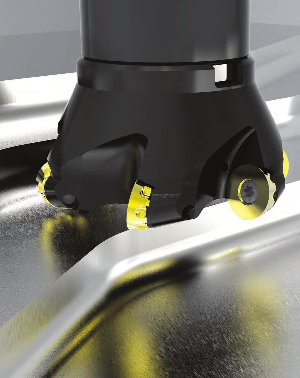
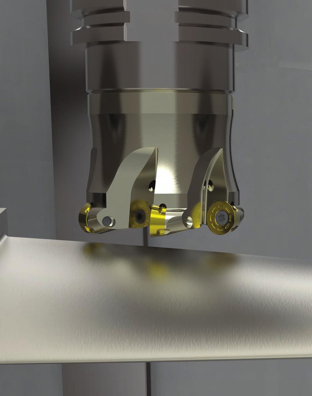
5 7792 High Feed Milling Patented Cutter Designs Patented Insert Designs Patented Grades To remove the highest volume of metal in the shortest possible time 3


6 7792 Patented High Feed Milling 7792: Increase Metal Removal Rate up to 90% or More! Modular 16mm 32mm Cutting diameters from 16mm to 160mm Modular, Weldon, Cylindrical and Shell Mill cutter configurations Modular Tungsten Extensions maintain stability in deep pocket applications All inserts feature 4 cutting edges Weldon 25mm 32mm The Patented 7792 Insert Cylindrical 16mm 32mm The unique 7792 insert design provides outstanding operational security and performance, with enhanced metal removal capability. Shell 40mm 160mm Maximize tool life, versatility and performance Face, Pocket, Shoulder, Profile, Helical Interpolate, Ramp, Copy and Mill Turn with one tool 6 grades for materials from Aluminium to Superalloys 4 insert sizes available Depth of cut from 0,90mm to 3,50mm Coarse, medium and fine pitch cutters available for all machining conditions. 4

7 7792 Patented High Feed Milling How High Feed Cutters Work The patented design of High Feed Cutters and Inserts combine to drive the cutting forces axially into the spindle. This allows even less rigid machines to outperform newer machines with conventional cutters by taking high feed, shallow cuts. 5 times the feed rate of conventional face mills High feed, shallow cuts Dramatically reduced cycle times Reduced vibration Better quality parts in less than half the time Twice the tool life or more Hard Case: The Ti Alpha Barrier The Alpha Casing, which forms during the cooling of the Titanium billet and varies in thickness and hardness, creates nearly impossible machining conditions. The previous most cost effective solution was to chemically remove it with acid. An aerospace customer was using our X-Grade inserts with our top performing button cutter on several titanium applications. This was our benchmark to test the Here s how the 7792VXD12 with X-500 Grade inserts performed on a Ti 6-4 Alpha Case 24% less energy consumed 120% increase in material removal rate Nearly 3 times the tool life The 7792 eliminated the need for highly toxic, dangerous chemicals and made effective Alpha Case machining a production reality. 5
8 7792VXP06 High Feed Milling Cutter d 1 L I 1 D Cylindrical Shank Product Dimensions (mm) Spares Item Description D L/H l 1 d 1 ap max 7792VXP06 Cylindrical Shank VXP06CA016Z2R , FP2506T TP7 1, VXP06CA020Z3R , FP2506T TP7 1, VXP06CA025Z4R , FP2507T TP7 1, VXP06CA032Z5R , FP2507T TP7 1,00 No. of Teeth Screw Tightening Nm M d 1 L D Modular Head Product Dimensions (mm) Spares Item Description D L/H M d 1 ap max 7792VXP06 Modular Head - Medium and Fine Pitch VXP06SA016Z2R M8 8,50 0, FP2506T TP7 1, VXP06SA020Z2R M10 10,50 0, FP2506T TP7 1, VXP06SA020Z3R M10 10,50 0, FP2506T TP7 1, VXP06SA025Z3R M12 12,50 0, FP2507T TP7 1, VXP06SA025Z4R M12 12,50 0, FP2507T TP7 1, VXP06SA032Z5R M16 17,00 0, FP2507T TP7 1,00 No. of Teeth Note: For cylindrical shank extensions in high density alloy with through coolant refer to page 45. Screw Tightening Nm 7792VXP06 Technical Information (mm) Product Item Description Facing Pitch Ramping Angle A B Dimensions Helical Hole min. - max. ap max Helical / Linear ae max Plunging Max RPM VXP06CA016Z2R140 7, ,60 3, VXP06CA020Z3R154 11, ,60 3, VXP06CA025Z4R154 16, ,60 3, VXP06CA032Z5R190 23, ,60 3, VXP06SA016Z2R25 7, ,60 3, VXP06SA020Z2R35 11, ,60 3, VXP06SA020Z3R35 11, ,60 3, VXP06SA025Z3R35 16, ,60 3, VXP06SA025Z4R35 16, ,60 3, VXP06SA032Z5R43 23, ,60 3, Helical Interpolation Flat Facing Pitch Ramp angle A uses one outside cutting edge only. Plunging Ramp angle B uses two cutting edges (one outside and one inside edge). A B Depth of Cut (ap) a p A = max ramp angle utilising full face contact B = max ramp angle utilising full contact + internal corner radius 6
9 7792VXP06 Milling Inserts & Recommended Feeds d XPLT06-D41 l Product Application & Material Dimensions (mm) Facing Slotting Plunging Item Description Grade Depth of Cut (mm) d (IC) l s r h m min ap max. 0,90 ap max. 0,90 ae max. 3, XPLT060308ER-D41 X400 7,00 7,00 3,18 0,80 0, XPLT060308ER-D41 X500 7,00 7,00 3,18 0,80 0, XPLT060308ER-D41 SP6519 7,00 7,00 3,18 0,80 0, XPLT060308ER-D41 SC6525 7,00 7,00 3,18 0,80 0,04 Machining Choice: 1 st Choice 2 nd Choice 3 rd Choice Material Guide Key descriptions found on page 19. r s 7792VXP06 Feeds f z (mm/tooth) Geometry Grade Operation Unalloyed Alloyed Stainless Stainless Refractory PH Gray Iron Spheroidal- Ductile Iron Malleable Iron Aluminium & Alloys <16% Si 116 HBN Aluminium & Silicon >16% Si 92 HBN HTA Iron Based Alloys HTA Cobalt Based Alloys HTA Nickel Based Alloys HTA Titanium Based Alloys Hard >1400 N/mm 2 >415 HBN Chilled Cast Iron >1400 N/mm 2 >400 HBN Min. - Max. Min. - Max. Min. - Max. Min. - Max. Min. - Max. Min. - Max. Min. - Max. Min. - Max. Min. - Max. Min. - Max. Min. - Max. Min. - Max. Min. - Max. Min. - Max. Min. - Max. ER-D41 X400 Facing 0,20-1,10 0,20-0, ,20-0,60 0,20-0,60 ER-D41 X400 Slotting 0,20-0,90 0,20-0, ,20-0,50 0,20-0,50 ER-D41 X400 Plunging 0,04-0,30 0,04-0, ,04-0,08 0,04-0,08 ER-D41 X500 Facing - - 0,15-1,00 0,15-0, ,15-0,50 0,15-0,50 0,15-0,50 0,15-0, ER-D41 X500 Slotting - - 0,15-0,80 0,15-0, ,10-0,40 0,10-0,40 0,10-0,40 0,10-0, ER-D41 X500 Plunging - - 0,04-0,20 0,04-0, ,04-0,06 0,04-0,06 0,04-0,06 0,04-0, ER-D41 SP6519 Facing 0,20-1,00 0,20-0,80 0,15-0,90 0,15-0,80 0,20-1,20 0,20-1,00 0,20-0,90 0,20-0,70-0,15-0,50 0,15-0,50 0,15-0,50 0,15-0, ER-D41 SP6519 Slotting 0,20-0,80 0,20-0,75 0,15-0,80 0,15-0,70 0,20-1,00 0,20-0,90 0,20-0,80 0,20-0,70-0,10-0,40 0,10-0,40 0,10-0,40 0,10-0, ER-D41 SP6519 Plunging 0,04-0,25 0,04-0,18 0,04-0,20 0,04-0,14 0,04-0,25 0,04-0,20 0,04-0,18 0,04-0,25-0,04-0,06 0,04-0,06 0,04-0,06 0,04-0, ER-D41 SC6525 Facing 0,20-0,95 0,20-0, ,20-1,20 0,20-1, ER-D41 SC6525 Slotting 0,20-0,78 0,20-0, ,20-1,00 0,20-0, ER-D41 SC6525 Plunging 0,04-0,23 0,04-0, ,04-0,25 0,04-0, Note: HTA = High Temperature Alloys Note: Speed recommendations can be found on page 14. 7
10 7792VXD09 High Feed Milling Cutter d 1 L I 1 D Weldon Shank d 1 L Product Dimensions (mm) Spares Item Description D L/H l 1 d 1 ap max 7792VXD09 Weldon Shank VXD09WA025Z2R , F3508T T15 2, VXD09WA032Z3R , F3510T T15 2, VXD09 Cylindrical Shank VXD09CA025Z2R , F3510T T15 2, VXD09CA032Z3R , F3510T T15 2, VXD09 Shell Mill Fixation - Coarse, Medium and Fine Pitch VXD09-A040Z3R , F3510T T15 2, VXD09-A040Z4R , F3510T T15 2, VXD09-A040Z5R , F3510T T15 2, VXD09-A050Z5R , F3510T T15 2, VXD09-A050Z6R , F3510T T15 2,10 No. of Teeth Screw Tightening Nm I 1 H D Cylindrical Shank d 1 Product Dimensions (mm) Spares Item Description D L/H M d 1 ap max 7792VXD09 Modular Head VXD09SA025Z2R M12 12,50 1, F3508T T15 2, VXD09SA032Z3R M16 17,00 1, F3510T T15 2,10 No. of Teeth Note: For cylindrical shank extensions in high density alloy with through coolant refer to page 45. Screw Tightening Nm D Shell Mill Fixation M d 1 L D Modular Head 7792VXD09 Technical Information (mm) Product Item Description Facing Pitch Ramping Angle A B Dimensions Helical Hole min. - max. ap max Helical / Linear ae max Plunging Max RPM VXD09WA025Z2R 11, ,00 6, VXD09WA032Z3R 18, ,00 6, VXD09CA025Z2R50 11, ,00 6, VXD09CA032Z3R70 18, ,00 6, VXD09-A040Z3R 26, ,00 6, VXD09-A040Z4R 26, ,00 6, VXD09-A040Z5R 26, ,00 6, VXD09-A050Z5R 36, ,00 6, VXD09-A050Z6R 36, ,00 6, VXD09SA025Z2R35 11, ,00 6, VXD09SA032Z3R43 18, ,00 6, Helical Interpolation Flat Facing Pitch Ramp angle A uses one outside cutting edge only. Plunging Ramp angle B uses two cutting edges (one outside and one inside edge). A B Depth of Cut (ap) a p A = max ramp angle utilising full face contact B = max ramp angle utilising full contact + internal corner radius 8
 ap max. 1,50 ap max. 1,50 ae max.")
11 7792VXD09 Milling Inserts & Recommended Feeds d XDLW09-D XDLT09-D41 XDLT09-D721 XDLT09-D411 l Product Application & Material Dimensions (mm) Item Description Grade Facing Slotting Plunging Depth of Cut (mm) ap max. 1,50 ap max. 1,50 ae max. 6,00 d (IC) l s r h m min XDLW090408SR-D X400 9,52 9,52 4,76 0,80 0, XDLW090408SR-D X500 9,52 9,52 4,76 0,80 0, XDLW090408SR-D SC3025 9,52 9,52 4,76 0,80 0, XDLT090408ER-D41 X500 9,52 9,52 4,76 0,80 0, XDLT090408ER-D41 SP6519 9,52 9,52 4,76 0,80 0, XDLT090408ER-D41 SC6525 9,52 9,52 4,76 0,80 0, XDLT090408ER-D721 GH2 9,52 9,52 4,76 0,80 0, XDLT090412ER-D411 X500 9,52 9,52 4,76 1,20 0, XDLT090412ER-D411 SP6519 9,52 9,52 4,76 1,20 0,05 Machining Choice: 1 st Choice 2 nd Choice 3 rd Choice Material Guide Key descriptions found on page 19. XDLW090408SR-D X500 should be used for Alloyed and Stainless with heavy scale. XDLT090412ER-D411 is a more positive geometry than the -D-41 with a larger radius which increases performance during smaller radial engagements or where chipping may occur when using the -D-41 geometry. XDLT090412ER-D411 uses less power than the -D-41 geometry. r s 7792VXD09 Feeds f z (mm/tooth) Geometry Grade Operation Unalloyed Alloyed Stainless Stainless Refractory PH Gray Iron Spheroidal- Ductile Iron Malleable Iron Aluminium & Alloys <16% Si 116 HBN Aluminium & Silicon >16% Si 92 HBN HTA Iron Based Alloys HTA Cobalt Based Alloys HTA Nickel Based Alloys HTA Titanium Based Alloys Hard >1400 N/mm 2 >415 HBN Chilled Cast Iron >1400 N/mm 2 >400 HBN Min. - Max. Min. - Max. Min. - Max. Min. - Max. Min. - Max. Min. - Max. Min. - Max. Min. - Max. Min. - Max. Min. - Max. Min. - Max. Min. - Max. Min. - Max. Min. - Max. Min. - Max. SR-D X400 Facing 0,30-2,00 0,30-1, ,30-1,00 0,30-1,00 SR-D X400 Slotting 0,30-1,50 0,30-1, ,30-0,60 0,30-0,80 SR-D X400 Plunging 0,10-0,25 0,10-0, ,10-0,12 0,10-0,12 SR-D X500 Facing - 0,30-1,90 0,30-1,20 0,30-1, SR-D X500 Slotting - 0,30-1,40 0,30-0,90 0,30-0, SR-D X500 Plunging - 0,10-0,22 0,10-0,20 0,10-0, SR-D SC3025 Facing ,30-2,00 0,30-1,80 0,30-1, SR-D SC3025 Slotting ,30-1,70 0,30-1,50 0,30-1, SR-D SC3025 Plunging ,10-0,25 0,10-0,22 0,10-0, ER-D41 X500 Facing - - 0,20-1,00 0,20-0, ,20-0,60 0,20-0,60 0,20-0,60 0,20-0, ER-D41 X500 Slotting - - 0,20-0,80 0,15-0, ,10-0,50 0,10-0,50 0,10-0,50 0,10-0, ER-D41 X500 Plunging - - 0,10-0,16 0,08-0, ,05-0,08 0,05-0,08 0,05-0,08 0,05-0, ER-D41 SP6519 Facing 0,30-1,50 0,30-1,30 0,20-1,00 0,20-0,60 0,30-1,50 0,30-1, ,20-0,60 0,20-0,60 0,20-0,60 0,20-0, ER-D41 SP6519 Slotting 0,30-1,30 0,30-1,00 0,20-0,80 0,15-0,50 0,30-1,30 0,30-1, ,10-0,50 0,10-0,50 0,10-0,50 0,10-0, ER-D41 SP6519 Plunging 0,10-0,20 0,10-0,16 0,10-0,16 0,05-0,08 0,10-0,20 0,10-0, ,05-0,08 0,05-0,08 0,05-0,08 0,05-0, ER-D41 SC6525 Facing 0,30-1,45 0,30-1, ,30-1,50 0,30-1, ER-D41 SC6525 Slotting 0,30-1,25 0,30-1, ,30-1,30 0,30-1, ER-D41 SC6525 Plunging 0,10-0,18 0,10-0, ,10-0,20 0,10-0, ER-D721 GH2 Facing ,30-1,50 0,30-1, ER-D721 GH2 Slotting ,30-1,30 0,30-1, ER-D721 GH2 Plunging ,10-0,20 0,10-0, ER-D411 X500 Facing - - 0,20-1,00 0,20-0, ,20-0,60 0,20-0,60 0,20-0,60 0,20-0, ER-D411 X500 Slotting - - 0,20-0,80 0,15-0, ,10-0,50 0,10-0,50 0,10-0,50 0,10-0, ER-D411 X500 Plunging - - 0,10-0,16 0,08-0, ,05-0,08 0,05-0,08 0,05-0,08 0,05-0, ER-D411 SP6519 Facing 0,30-1,50 0,30-1,30 0,20-1,00 0,20-0,60 0,30-1,50 0,30-1, ,20-0,60 0,20-0,60 0,20-0,60 0,20-0, ER-D411 SP6519 Slotting 0,30-1,30 0,30-1,00 0,20-0,80 0,15-0,50 0,30-1,30 0,30-1, ,10-0,50 0,10-0,50 0,10-0,50 0,10-0, ER-D411 SP6519 Plunging 0,10-0,20 0,10-0,16 0,10-0,16 0,05-0,08 0,10-0,20 0,10-0, ,05-0,08 0,05-0,08 0,05-0,08 0,05-0, Note: HTA = High Temperature Alloys Note: Speed recommendations can be found on page 14. 9
12 7792VXD12 High Feed Milling Cutter d 1 H L I 1 D Cylindrical Shank d 1 D Shell Mill Fixation Product Dimensions (mm) Spares Item Description D L/H l 1 d 1 ap max 7792VXD12 Cylindrical Shank VXD12CA032Z2R , D4010T T15 3, VXD12 Shell Mill Fixation - Coarse, Medium and Fine Pitch VXD12-A052Z3R , D4012T T15 3, VXD12-A052Z4R , D4012T T15 3, VXD12-A052Z5R , D4010T T15 3, VXD12-A063Z4R , D4012T T15 3, VXD12-A063Z5R , D4012T T15 3, VXD12-A066Z4R , D4012T T15 3, VXD12-A066Z5R , D4012T T15 3, VXD12-A080Z5R , D4012T T15 3, VXD12-A080Z8R , D4012T T15 3, VXD12-A100Z6R , D4012T T15 3, VXD12-A100Z9R , D4012T T15 3, VXD12-A125Z8R , D4012T T15 3, VXD12-A125Z11R , D4012T T15 3, VXD12-160Z07R D4012T T15 3,10 No. of Teeth Screw Tightening Nm M L d 1 D Product Dimensions (mm) Spares Item Description D L/H M d 1 ap max 7792VXD12 Modular Head VXD12SA032Z2R M16 17,00 2, D4010T T15 3,10 No. of Teeth Note: For cylindrical shank extensions in high density alloy with through coolant refer to page 45. Screw Tightening Nm Modular Head Depth of Cut (ap) a p 7792VXD12 Technical Information (mm) Product Item Description Facing Pitch Ramping Angle A B Dimensions Helical Hole min. - max. ap max Helical / Linear ae max Plunging Max RPM VXD12CA032Z2R70 10, ,80 9, VXD12-A052Z3R 33, ,80 9, VXD12-A052Z4R 33, ,80 9, VXD12-A052Z5R 33, ,80 9, VXD12-A063Z4R 44, ,80 9, VXD12-A063Z5R 44, ,80 9, VXD12-A066Z4R 47, ,80 9, VXD12-A066Z5R 47, ,80 9, VXD12-A080Z5R 61, ,80 9, VXD12-A080Z8R 61, ,80 9, VXD12-A100Z6R 81, ,80 9, VXD12-A100Z9R 81, ,80 9, VXD12-A125Z8R 106, ,80 9, VXD12-A125Z11R 106, ,80 9, VXD12-160Z07R 141, ,80 9, VXD12SA032Z2R43 10, ,80 9, Helical Interpolation Flat Facing Pitch Ramp angle A uses one outside cutting edge only. Plunging Ramp angle B uses two cutting edges (one outside and one inside edge). A = max ramp angle utilizing full face contact B = max ramp angle utilizing full contact + internal corner radius A B 10
13 7792VXD12 Milling Inserts & Recommended Feeds d XDLW12-D XDLT12-D41 XDLT12-D721 XDLT12-D411 l Product Application & Material Dimensions (mm) Item Description Grade Facing Slotting Plunging Depth of Cut (mm) ap max. 2,50 ap max. 2,00 ae max. 9, XDLW120508SR-D X400 12,70 12,70 5,56 0,80 0, XDLW120508SR-D X500 12,70 12,70 5,56 0,80 0, XDLW120508SR-D SC ,70 12,70 5,56 0,80 0, XDLT120508ER-D41 X500 12,70 12,70 5,56 0,80 0, XDLT120508ER-D41 SP ,70 12,70 5,56 0,80 0, XDLT120508ER-D41 SC ,70 12,70 5,56 0,80 0, XDLT120508ER-D721 GH2 12,70 12,70 5,56 0,80 0, XDLT120512ER-D411 X500 12,70 12,70 5,56 1,20 0, XDLT120512ER-D411 SP ,70 12,70 5,56 1,20 0,05 Machining Choice: 1 st Choice 2 nd Choice 3 rd Choice Material Guide Key descriptions found on page 19. XDLW120508SR-D X500 should be used for Alloyed and Stainless with heavy scale. 7792VXD12 Feeds f z (mm/tooth) d (IC) l s r h m min XDLT120512ER-D411 is a more positive geometry than the -D41 with a larger radius which increases performance during smaller radial engagements or where chipping may occur when using the -D41 geometry. XDLT120512ER-D411 uses less power than the -D41 geometry. r s Geometry Grade Operation Unalloyed Alloyed Stainless Stainless Refractory PH Gray Iron Spheroidal- Ductile Iron Malleable Iron Aluminium & Alloys <16% Si 116 HBN Aluminium & Silicon >16% Si 92 HBN HTA Iron Based Alloys HTA Cobalt Based Alloys HTA Nickel Based Alloys HTA Titanium Based Alloys Hard >1400 N/mm 2 >415 HBN Chilled Cast Iron >1400 N/mm 2 >400 HBN Min. - Max. Min. - Max. Min. - Max. Min. - Max. Min. - Max. Min. - Max. Min. - Max. Min. - Max. Min. - Max. Min. - Max. Min. - Max. Min. - Max. Min. - Max. Min. - Max. Min. - Max. SR-D X400 Facing 0,30-2,70 0,30-2, ,30-1,20 0,30-1,50 SR-D X400 Slotting 0,30-2,50 0,30-2, ,30-0,80 0,30-1,00 SR-D X400 Plunging 0,10-0,30 0,10-0, ,10-0,13 0,10-0,15 SR-D X500 Facing - 0,30-2,50 0,20-1,70 0,20-1, SR-D X500 Slotting - 0,30-2,40 0,20-1,50 0,20-1, SR-D X500 Plunging - 0,10-0,24 0,10-0,25 0,10-0, SR-D SC3025 Facing ,30-3,00 0,30-2,80 0,30-2, SR-D SC3025 Slotting ,30-2,50 0,30-2,30 0,30-2, SR-D SC3025 Plunging ,10-0,30 0,10-0,28 0,10-0, ER-D41 X500 Facing - - 0,20-1,40 0,20-0, ,20-0,85 0,20-0,85 0,20-0,85 0,20-1, ER-D41 X500 Slotting - - 0,20-1,10 0,20-0, ,10-0,70 0,10-0,70 0,10-0,70 0,10-0, ER-D41 X500 Plunging - - 0,10-0,20 0,08-0, ,05-0,10 0,05-0,10 0,05-0,10 0,05-0, ER-D41 SP6519 Facing 0,30-2,50 0,30-2,00 0,20-1,20 0,20-0,75 0,30-2,50 0,30-2, ,20-0,85 0,20-0,85 0,20-0,85 0,20-1, ER-D41 SP6519 Slotting 0,30-2,00 0,30-1,60 0,20-1,00 0,15-0,60 0,30-2,00 0,30-1, ,10-0,70 0,10-0,70 0,10-0,70 0,10-0, ER-D41 SP6519 Plunging 0,10-0,22 0,10-0,18 0,10-0,18 0,05-0,10 0,10-0,22 0,10-0, ,05-0,10 0,05-0,10 0,05-0,10 0,05-0, ER-D41 SC6525 Facing 0,30-2,40 0,30-2, ,30-2,50 0,30-2, ER-D41 SC6525 Slotting 0,30-1,90 0,30-1, ,30-2,00 0,30-1, ER-D41 SC6525 Plunging 0,10-0,20 0,10-0, ,10-0,22 0,10-0, ER-D721 GH2 Facing ,30-1,50 0,30-1, ER-D721 GH2 Slotting ,30-1,50 0,30-1, ER-D721 GH2 Plunging ,10-0,40 0,10-0, ER-D411 X500 Facing - - 0,20-1,40 0,20-0, ,20-0,85 0,20-0,85 0,20-0,85 0,20-1, ER-D411 X500 Slotting - - 0,20-1,10 0,20-0, ,10-0,70 0,10-0,70 0,10-0,70 0,10-0, ER-D411 X500 Plunging - - 0,10-0,20 0,08-0, ,05-0,10 0,05-0,10 0,05-0,10 0,05-0, ER-D411 SP6519 Facing 0,30-2,50 0,30-2,30 0,20-1,20 0,20-0,75 0,30-2,50 0,30-2, ,20-0,85 0,20-0,85 0,20-0,85 0,20-1, ER-D411 SP6519 Slotting 0,30-2,00 0,30-1,80 0,20-1,00 0,15-0,60 0,30-2,00 0,30-1, ,10-0,70 0,10-0,70 0,10-0,70 0,10-0, ER-D411 SP6519 Plunging 0,10-0,22 0,10-0,18 0,10-0,18 0,05-0,10 0,10-0,22 0,10-0, ,05-0,10 0,05-0,10 0,05-0,10 0,05-0, Note: HTA = High Temperature Alloys Note: Speed recommendations can be found on page
14 7792VXE16 High Feed Milling Cutter d 1 H L I 1 D Cylindrical Shank d 1 Product Dimensions (mm) Spares Item Description D L/H l 1 d 1 ap max 7792VXE16 Cylindrcal Shank VXE16CA040Z2R , DP5013T TP20 6, VXE16CA050Z3R , DP5013T TP20 6, VXE16 Shell Mill Fixation VXE16-A063Z5R , DP5013T TP20 6, VXE16-A080Z6R , DP5013T TP20 6, VXE16-A100Z8R , DP5013T TP20 6, VXE16-A125Z10R , DP5013T TP20 6, VXE16-160Z , DP5013T TP20 6,10 No. of Teeth Screw Tightening Nm D Shell Mill Fixation 7792VXE16 Technical Information (mm) Product Item Description Facing Pitch Ramping Angle A B Dimensions Helical Hole min. - max. ap max Helical / Linear ae max Plunging Max RPM VXE16CA040Z2R102 16, VXE16CA050Z3R102 25, VXE16-A063Z5R 37, , VXE16-A080Z6R 54, , VXE16-A100Z8R 74, , VXE16-A125Z10R 99, , VXE16-160Z12 134, , Helical Interpolation Flat Facing Pitch Ramp angle A uses one outside cutting edge only. Plunging Ramp angle B uses two cutting edges (one outside and one inside edge). A B Depth of Cut (ap) a p A = max ramp angle utilising full face contact B = max ramp angle utilising full contact + internal corner radius 12
15 7792VXE16 Milling Inserts & Recommended Feeds d XELW16-D XELT16-D41 l Product Application & Material Dimensions (mm) Facing Slotting Plunging Item Description Grade Depth of Cut (mm) d (IC) l s r h m min ap max. 3,50 ap max. 3,00 ae max.13, XELW160512SR-D X400 16,80 16,80 5,56 1,20 0, XELW160512SR-D SC ,80 16,80 5,56 1,20 0, XELT160512ER-D41 X500 16,80 16,80 5,56 1,20 0, XELT160512ER-D41 SP ,80 16,80 5,56 1,20 0, XELT160512ER-D41 SC ,80 16,80 5,56 1,20 0,12 Machining Choice: 1 st Choice 2 nd Choice 3 rd Choice Material Guide Key descriptions found on page 19. r s 7792VXE16 Feeds f z (mm/tooth) Geometry Grade Operation Unalloyed Alloyed Stainless Stainless Refractory PH Gray Iron Spheroidal- Ductile Iron Malleable Iron Aluminium & Alloys <16% Si 116 HBN Aluminium & Silicon >16% Si 92 HBN HTA Iron Based Alloys HTA Cobalt Based Alloys HTA Nickel Based Alloys HTA Titanium Based Alloys Hard >1400 N/mm 2 >415 HBN Chilled Cast Iron >1400 N/mm 2 >400 HBN Min. - Max. Min. - Max. Min. - Max. Min. - Max. Min. - Max. Min. - Max. Min. - Max. Min. - Max. Min. - Max. Min. - Max. Min. - Max. Min. - Max. Min. - Max. Min. - Max. Min. - Max. SR-D X400 Facing 0,30-2,00 0,30-1, ,30-0,80 0,30-1,00 SR-D X400 Slotting 0,30-1,70 0,30-1, ,30-0,50 0,30-0,60 SR-D X400 Plunging 0,10-0,27 0,10-0, ,10-0,10 0,10-0,12 SR-D SC3025 Facing ,30-2,00 0,30-1,80 0,30-1, SR-D SC3025 Slotting ,30-1,50 0,30-1,30 0,30-1, SR-D SC3025 Plunging ,10-0,20 0,10-0,18 0,10-0, ER-D41 X500 Facing - - 0,20-1,00 0,20-0, ,20-0,60 0,20-0,60 0,20-0,60 0,20-0, ER-D41 X500 Slotting - - 0,20-0,80 0,20-0, ,10-0,40 0,10-0,40 0,10-0,40 0,10-0, ER-D41 X500 Plunging - - 0,12-0,16 0,07-0, ,05-0,10 0,05-0,10 0,05-0,10 0,05-0, ER-D41 SP6519 Facing 0,30-1,50 0,30-1,30 0,20-1,00 0,20-0,50 0,30-1,50 0,30-1, ,20-0,60 0,20-0,60 0,20-0,60 0,20-0, ER-D41 SP6519 Slotting 0,30-1,30 0,30-1,20 0,20-0,80 0,20-0,45 0,30-1,20 0,30-1, ,10-0,40 0,10-0,40 0,10-0,40 0,10-0, ER-D41 SP6519 Plunging 0,10-0,23 0,10-0,20 0,12-0,16 0,07-0,12 0,10-0,20 0,10-0, ,05-0,10 0,05-0,10 0,05-0,10 0,05-0, ER-D41 SC6525 Facing 0,30-1,40 0,30-1, ,30-1,50 0,30-1, ER-D41 SC6525 Slotting 0,30-1,20 0,30-1, ,30-1,20 0,30-1, ER-D41 SC6525 Plunging 0,10-0,20 0,10-0, ,10-0,20 0,10-0, Note: HTA = High Temperature Alloys Note: Speed recommendations can be found on page
16 7792VX Recommended Speeds Speed v c (m/min) 7792VX Series Coolant Recommendation Recommended Possible -- + PVD X Grade CVD X Grade Wear Resistance Speed min. - max. PVD Standard Uncoated Micrograin CVD Standard CVD Standard ISO P M K Materials Unalloyed Alloyed Stainless PH Stainless Cast Iron Rm and Hardness <600 N/mm 2 <180 HBN <950 N/mm 2 <280 HBN N/mm HBN N/mm HBN N/mm HBN Austenitic + Ferritic 300 series Martensitic 400 series Refractory P.H. Grey GG-Ft Spheroidal-Ductile GGG-FGS Malleable GTS - MN/MP X400 X500 SP6519 GH2 SC6525 SC N Aluminium & Alloys Aluminium & Alloys < 16% Si 116 HBN Aluminium + Silicon > 16% Si 92 HBN Iron Based S High Temperature Alloys Cobalt Based Nickel Based Titanium Based H Hard Materials Hard >1400 N/mm 2 >415 HBN Chilled Cast Iron >1400 N/mm 2 > 400 HBN

17 7792VX Technical Information Plunging Tool Scallop Height The scallop height is calculated in relation to the step over. Stepover The maximum radial engagement is directly in relation to insert cutting edge length. Insert Workpiece a e (Maximum) The cutting edge should not be in contact with the material face after machining to maintain the cutting edge quality. For insert type: XP 06 the ae, max is 3mm. For insert type: XD 09 the ae, max is 6mm. For insert type: XD 12 the ae, max is 9mm. For insert type: XE 16 the ae, max is 13mm. Plunging Information (mm) tool definition-scallop height and step over Diameter Insert size a e max Scallop height Tool definition (mm) 7792VXP VXD VXD VXE Step over (mm) 0,25 3,97 4,44 4,97 5,63 4,97 5,63 6,30 7,05 5,63 7,19 7,92 8,11 8,93 9,99 11,17 12,64 7,92 8,93 9,99 11,17 12,64 0,50 5,57 6,24 7,00 7,94 7,00 7,94 8,89 9,95 7,94 10,15 11,18 11,44 12,61 14,11 15,78 17,86 11,18 12,61 14,11 15,78 17,86 0,75 6,76 7,60 8,53 9,68 8,53 9,68 10,85 12,16 9,68 12,40 13,67 13,99 15,42 17,26 19,31 21,86 13,67 15,42 17,26 19,31 21,86 1,00 7,75 8,72 9,80 11,14 9,80 11,14 12,49 14,00 11,14 14,28 15,75 16,12 17,78 19,90 22,27 25,22 15,75 17,78 19,90 22,27 25,22 2,00 10,58 12,00 13,56 15,49 13,56 15,49 17,44 19,60 15,49 20,00 22,09 22,63 24,98 28,00 31,37 35,55 22,09 24,98 28,00 31,37 35,55 3,00 12,49 14,28 16,25 18,65 16,25 18,65 21,07 23,75 18,65 24,25 26,83 27,49 30,40 34,12 38,26 43,41 26,83 30,40 34,12 38,26 43,41 4,00 18,33 21,17 24,00 27,13 21,17 27,71 30,72 31,50 34,87 39,19 44,00 49,96 30,72 34,87 39,19 44,00 49,96 5,00 20,00 23,24 26,46 30,00 23,24 30,66 34,06 34,93 38,73 43,59 48,99 55,68 34,06 38,73 43,59 48,99 55,68 6,00 21,35 24,98 28,57 32,49 24,98 33,23 36,99 37,95 42,14 47,50 53,44 60,79 36,99 42,14 47,50 53,44 60,79 7,00 26,46 35,50 39,60 40,64 45,21 51,03 57,48 65,45 39,60 45,21 51,03 57,48 65,45 8,00 27,71 37,52 41,95 43,08 48,00 54,26 61,19 69,74 41,95 48,00 54,26 61,19 69,74 9,00 28,77 39,34 44,09 45,30 50,56 57,24 64,62 73,73 44,09 50,56 57,24 64,62 73,73 10,00 46,04 52,92 60,00 67,82 77,46 11,00 47,83 55,10 62,58 70,82 80,97 12,00 49,48 57,13 64,99 73,65 84,29 13,00 50,99 59,03 67,26 76,32 87,43 Max. flat surface (mm) Insert size Cutter dia. Pitch 16 7, , , , , , , , , , , , , , , , , , , , ,50 Helical Interpolation Flat Facing Pitch Helical interpolation capacity for 7792VX (mm) Insert Size Cutter dia. Hole min. Hole max


 irrespective of position in cavity.")
18 7792VX Technical Information The advantages of face milling and producing cavities with Stellram s high feed face mill are numerous. The unique design of the insert, approach angle and the cutter body ensure the cutting forces are predominantly directed in the axial direction. The example shown with a round insert tool shows complex forces which result in high levels of vibration and damage to the cutting edge. 7792VX Cutting forces predominantly axial Relationship between cutting edge and work piece is at its most stable. Results in high feed rates and consistent tool life. Round Insert Tools Tangential forces act around the radius Leads to vibration and damage of the cutting edge Leads to reduced feed and lower productivity The 7792VX machines with a constant volume of chip throughout all aspects of producing cavities and produces a side wall that is close to profile. Round insert tools have increasing chip volume through the process. 7792VX Constant cutting section (chip volume) irrespective of position in cavity. Producing a close to profile side wall. Near-square side walls possible. Centre clearance Round insert Greater surface contact. Increased chip section for side wall machining. Vibration in corners. Side wall Undulating side wall cusps. 16

19 7792VX Technical Information CNC Program - Corner Radius Definition The use of common CAD / CAM systems requires a round insert dimension to be known for cavity machining. This is available with 7792VX cutters as shown to the right and in the reference table. Programming Data (mm) Insert size (mm) Radius R L 06 0,80 1,37 0, ,80 2,01 0,73 1,20 2,27 0,67 For finish pass applications: R L 0,80 2,50 1, ,20 2,73 0, ,20 4,18 1,46 Wiper Facet for finishing use max. feed 0,80mm/Revolution Calculation of the average chip thickness in relation with the D.O.C. (Axial) Formula: Programme Feed Rate (f z ) f z = h m x d a p h m = Average chip thickness Formula: Average Chip Thickness (h m ) a p = Depth of cut f z = Feed per tooth h m = f z x a p d = Insert diameter 45mm d Theoretical Diameter for all high feed insert sizes = 45mm Calculation of the average chip thickness in relation with the a e (Radial Engagement) if a e is less than 50% of Dia. Formula: Programme Feed Rate (f z ) f z = h m x d a e h m = Average chip thickness a e = Radial engagement f z = Feed per tooth d = Cutter diameter Formula: Average Chip Thickness (h m ) h a m = f z x e d 17


 Insert Grade: X500 Cycle time: 1 hour 20 minutes 75% Reduction in")
 Insert Grade: X500 Process: Mill turning Workpiece rotates on")
20 7792 Case Histories 7792 Case Histories Material: 4140 steel HBN Industry: Die/Mold Job: 17 holes 51,59mm diameter, 67,74mm deep Cycle time: 4.5 hours 7792 Solution: Cutter: Modular 7792VXD09 (25mm Cutter) Extension: Anti-vibration, heavy-alloy Modular Shank Insert Grade: X400 Process: High Feed Helical Interpolation Cycle time: 1 minute 45 seconds per hole Total Cycle time: 30 minutes 90% Reduction in Cycle Time Material: 6-4 Titanium Job: Machine pockets in aerospace component Cycle time: 5.5 hours 7792 Solution: Cutter: 7792VXD12 (160mm Cutter) Insert Grade: X500 Cycle time: 1 hour 20 minutes 75% Reduction in Cycle Time Material: 6-4 Titanium Job: Turn a 1463mm diameter by 340mm deep ring Industry: Aerospace Turning Cycle time: 4 hours 35 minutes 7792 Solution: Cutter: 7792VXE16 (125mm Cutter) Insert Grade: X500 Process: Mill turning Workpiece rotates on B axis at 0,26 RPM Spiral milling feed rate of 60mm per revolution Cycle time: 2 hours 24 minutes Spiral Milling Cuts Cycle Time 48% 18
21 7792 Patented High Feed Milling High Feed Geometries -D P P K H Fully ground with flat top and variable hone. Hardened Materials up to 480HBN. -D41 M M S Positive geometry that reduces power consumption. -D411 M M S Positive geometry with larger corner radius (1,2mm) reduces cutting energy and provides better edge protection during lower radial engagement applications. -D721 N Positive, periphery ground, polished top rake face and sharp edge allows a freer cutting action and reduces built-up edge. Material Guide Key to Recommended Inserts Material Designation P Unalloyed s P Alloyed s M Stainless s M PH Stainless K Cast Irons N Aluminum & Alloys S High Temp. Alloys H Hard Materials 19


22 High Feed Grades High Feed Grades GH2 N Uncoated Micrograin Tough and able to handle high pressure, vibration and shock. X400 P P H Coating Type: PVD, TiAlN Designed for high metal removal rates and interrupted cuts. X500 M S Coating Type: CVD, TiN-TiC-TiN High level of shock resistance; operates at low to medium cutting speeds; high metal removal rates. SC3025 K Coating Type: CVD, TiN - TiCN - Al 2 O 3 Multi-layer CVD coating offers wear and abrasion resistance. SC6525 P P K Coating Type: CVD, TiN-TiCN-Al 2 O 3 High Performance Machining at elevated surface speeds. SP6519 M Coating Type: PVD, TiAlN Super nano coating is extremely hard for unmatched performance and virtually eliminates residual stress. Material Guide Key to Recommended Inserts Material Designation P Unalloyed s P Alloyed s M Stainless s M PH Stainless K Cast Irons N Aluminum & Alloys S High Temp. Alloys H Hard Materials 20

23 Patented Cutter Designs Patented Insert Designs Patented Grades The 77 Family Excellent for roughing, semi-finishing and finishing of high-performance materials 21

 This collection of cutters shows the dynamics of Kennametal")


24 77 Family Заказ инструмента: 8 (343) sales@sverla-ekb.ru The 77 Family Modular 16mm 40mm Weldon 25mm Three Families of Cutters are Featured: 7700VR08 small diameter standard button cutters (Cylindrical, Weldon and Modular: 16mm to 32mm) 7710VRD20 Anti-Rotation Shell Mill cutters (63mm to 160mm) 7713VR10 and 12 Patented Anti-Rotation Cutters (Cylindrical, Modular and Shell: 20mm to 80mm) This collection of cutters shows the dynamics of Kennametal technology taking the conventional to the highest level to machine the toughest high performance alloys. Cylindrical 16mm 32mm Shell 40mm 160mm Continuous Cutting Under the Toughest Conditions Cutter diameters from 16mm to 160mm Maximum number of teeth for heavy feed operations Medium and close pitch cutters available Round button insert for maximum strength 8mm to 20mm insert diameters Low cutting forces Flute design maximizes chip evacuation Satin Silver coating extends cutter body life (only 7713VR series) Modular tools feature an Anti-Vibration Tungsten Extension with Through Coolant 22


25 77 Family VRD / VR Anti-Rotation Technology High Flute Design Maximum Chip Evacuation The High Flute Indexing Cutter The 7710 and 7713 series cutters feature a unique patented pocket system that locks the inserts into position to prevent inserts from moving during heavy machining. Through Coolant and unique flow through pocket design maximise chip evacuation and increase tool life Through Tool Coolant 7713 Patented series cutter bodies are armored with Satin Silver plating to protect body integrity in milling high performance materials. Maximum Tool Life Heavy Cut Geometries The Positive Indexing Round Insert The Anti-Rotation insert features four, five or eight locking positions which mate with the pocket of the cutter body. Positive positioning of the insert throughout the heaviest cuts Maximum indexes to optimize tool life and reduce tooling costs Locking Positions 23
26 7700VR08 Copy Milling Cutter d 1 L I 1 D Da* Weldon Shank d 1 Product Dimensions (mm) Spares Item Description Da* D L/H l 1 d 1 ap max 7700VR08 Weldon Shank VR08WA025R070-M F3006T T9 1, VR08WA025R124-M F3006T T9 1, VR08 Cylindrical Shank - Medium and Fine Pitch VR08CA020Z3R F3006T T9 1, VR08CA025Z3R F3006T T9 1, VR08CA025Z4R F3006T T9 1, VR08CA032Z4R F3006T T9 1, VR08CA032Z5R F3006T T9 1,40 D = Effective Diameter (Axis) from insert centreline to centreline. Da* = Outside Diameter No. of teeth Screw Tightening Nm L I 1 D Da* Cylindrical Shank Product Dimensions (mm) Spares Item Description Da* D L/H M d 1 ap max 7700VR08 Modular Head - Medium and Fine Pitch VR08SA016Z2R M F3006T T9 1, VR08SA020Z3R M F3006T T9 1, VR08SA025Z3R M F3006T T9 1, VR08SA025Z4R M F3006T T9 1, VR08SA032Z5R M F3006T T9 1,40 D = Effective Diameter (Axis) from insert centreline to centreline. Da* = Outside Diameter No. of teeth Note: For Cylindrical Shank extensions in high density alloy with through coolant refer to page 45. Screw Tightening Nm M d 1 L 7700VR08 Technical Information (mm) Product Dimensions D Da* Modular Head a p Item Description Facing Pitch Ramping Angle Helical Hole min. - max. ap max Helical / Max RPM Linear VR08WA025R070-M , VR08WA025R124-M , VR08CA020Z3R , VR08CA025Z3R , VR08CA025Z4R , VR08CA032Z4R , VR08CA032Z5R , VR08SA016Z2R , VR08SA020Z3R , VR08SA025Z3R , VR08SA025Z4R , VR08SA032Z5R , Ramping Flat Facing Pitch Helical Interpolation Depth of Cut (ap) 24
 a p max a p min - max a p min - max - 0.")

27 7700VR08 Milling Inserts & Recommended Feeds RPEX RPMT08-41 RPHT Product Application & Material Dimensions (mm) Roughing Semi-Finishing Finishing d s Item Description Grade Depth of Cut (mm) a p max a p min - max a p min - max - 0.,80-1,50 0,10-0, RPEX0803M3F-701 SP4019-8,00-3,18 4,00 0, RPEX0803M3F-701 GH1-8,00-3,18 4,00 0, RPEX0803M3E-701 X ,00-3,18 4,00 0, RPEX0803M3E-701 SP ,00-3,18 4,00 0, RPMT0803M3E-41 X500-8,00-3,18 4,00 0, RPMT0803M3E-41 SP6519-8,00-3,18 4,00 0, RPMT0803M3E-41 MP91M - 8,00-3,18 4,00 0, RPHT0803M3E-422 X500-8,00-3,18 4,00 0, RPHT0803M3E-422 SP6519-8,00-3,18 4,00 0,03 Machining Choice: 1 st Choice 2 nd Choice 3 rd Choice Material Guide Key descriptions found on page 46. d (IC) l s r hm min 7700VR08 Feeds f z (mm/tooth) Geometry Grade Operation Unalloyed Alloyed Stainless Stainless Refractory PH Gray Iron Spheroidal- Ductile Iron Malleable Iron Aluminium & Alloys <16% Si 116 HBN Aluminium & Silicon >16% Si 92 HBN HTA Iron Based Alloys HTA Cobalt Based Alloys HTA Nickel Based Alloys HTA Titanium Based Alloys Hard >1400 N/mm 2 >415 HBN Chilled Cast Iron >1400 N/mm 2 >400 HBN Min. - Max. Min. - Max. Min. - Max. Min. - Max. Min. - Max. Min. - Max. Min. - Max. Min. - Max. Min. - Max. Min. - Max. Min. - Max. Min. - Max. Min. - Max. Min. - Max. Min. - Max. F-701 SP4019 Contouring ,02-0,08 0,02-0,06 0,02-0,06 0,02-0,06 0,02-0,07 0,02-0, F-701 GH1 Contouring ,02-0,08 0,02-0, E-701 X500 Contouring ,02-0,06 0,02-0,06 0,02-0,07 0,02-0, E-701 SP6519 Contouring - - 0,02-0,10 0,02-0, ,02-0,06 0,02-0,06 0,02-0,07 0,02-0, E-41 X500 Contouring - - 0,03-0,12 0,03-0, E-41 SP6519 Contouring 0,03-0,14 0,03-0,12 0,03-0,12 0,03-0,10 0,03-0,14 0,03-0,14 0,03-0, E-41 MP91M Contouring 0,03-0, ,03-0,13 0,03-0,13 0,03-0, E-422 X500 Contouring - 0,03-0,12 0,03-0,14 0,03-0, ,03-0,08 0,03-0,08 0,03-0,09 0,03-0, E-422 SP6519 Contouring 0,03-0,14 0,03-0,12 0,03-0,14 0,03-0,11 0,03-0,14 0,03-0,14 0,03-0, ,03-0,08 0,03-0,08 0,03-0,09 0,03-0, Note: HTA = High Temperature Alloys Note: Speed recommendations can be found on page
28 7700VR Recommended Speeds Speed v c (m/min) 7700VR Series -- Wear Resistance + Coolant Recommendation Recommended Possible CVD X Grade PVD X Grade PVD Standard Speed min. - max. Uncoated Micrograin PVD Standard CVD Standard Uncoated Micrograin ISO Materials Rm and Hardness X500 X700 SP6519 GH2 SP4019 MP91M GH1 P M Unalloyed Alloyed Stainless PH Stainless <600 N/mm 2 <180 HBN <950 N/mm 2 <280 HBN N/mm HBN N/mm HBN N/mm HBN Austenitic + Ferritic 300 series Martensitic 400 series Refractory P.H K N Cast Iron Aluminium & Alloys Grey GG-Ft Spheroidal-Ductile GGG-FGS Malleable GTS - MN/MP Aluminium & Alloys < 16% Si 116 HBN Aluminium + Silicon > 16% Si 92 HBN Iron Based S High Temperature Alloys Cobalt Based Nickel Based Titanium Based H Hard Materials Hard >1400 N/mm 2 >415 HBN Chilled Cast Iron >1400 N/mm 2 > 400 HBN 26
29 7700VR Technical Information 7700VR Technical Information Working Diameter: D w = D x r 2 - (r -a p ) 2 r D 2 D w a p where: D w = Working Diameter D 2 = Diameter of cutter insert centre to centre r = Insert radius = Axial Depth of Cut a p 7710VR Technical Information where: f z = Feed per tooth h m = Average chip thickness r = Insert radius a e = Radial Depth of Cut a p = Axial Depth of Cut Formula to find programmed feed rate based on radial engagement and axial depth of cut. f z = r 2 -( r - a e ) 2 x r Formula to calculate the average chip thickness hm in relation with radial engagement and depth of cut. h m r 2 -( r - a p ) 2 r h m = f z x r 2 - ( r - a e ) 2 r x r 2 - ( r - a p ) 2 r Simplified formulas to evaluate hm and fz based on radial engagement or depth of cut. Calculation of the average chip thickness in relation with the D.O.C. (Axial) Formula: Programme Feed Rate (f z ) f z = h m x d a p h m = Average chip thickness a p = Depth of cut f z = Feed per tooth d = Insert diameter Formula: Average Chip Thickness (h m ) a h m = f z x p d Calculation of the average chip thickness in relation with the a e (Radial Engagement) if a e is less than 50% of Dia. Formula: Programme Feed Rate (f z ) f z = h m x d a e h m = Average chip thickness a e = Radial engagement f z = Feed per tooth d = Cutter diameter Formula: Average Chip Thickness (h m ) h m = f z x a e d 27
30 7700VR Technical Information With round inserts, the thickness of the chip varies depending on the axial depth of cut (ap) and is related to the size of the cutting edge-preparation. For best tool life it is important to maintain the proper chip thickness as shown below. 7700VR08 Inserts RP Inserts Geometry F-701 E-701 E-41 E-422 Insert Size Dimensions (mm) ap Axial hm min. hm max. fz min. fz max. d.o.c. 8,00 0,25 0,02 0,05 0,11 0,28 8,00 0,50 0,02 0,05 0,08 0,20 8,00 0,75 0,02 0,05 0,07 0,16 8,00 1,00 0,02 0,05 0,06 0,14 8,00 1,25 0,02 0,05 0,05 0,13 8,00 1,50 0,02 0,05 0,05 0,12 8,00 0,25 0,02 0,05 0,11 0,28 8,00 0,50 0,02 0,05 0,08 0,20 8,00 0,75 0,02 0,05 0,07 0,16 8,00 1,00 0,02 0,05 0,06 0,14 8,00 1,25 0,02 0,05 0,05 0,13 8,00 1,50 0,02 0,05 0,05 0,12 8,00 0,25 0,03 0,06 0,17 0,34 8,00 0,50 0,03 0,06 0,12 0,24 8,00 0,75 0,03 0,06 0,10 0,20 8,00 1,00 0,03 0,06 0,08 0,17 8,00 1,25 0,03 0,06 0,08 0,15 8,00 1,50 0,03 0,06 0,07 0,14 8,00 0,25 0,03 0,07 0,17 0,40 8,00 0,50 0,03 0,07 0,12 0,28 8,00 0,75 0,03 0,07 0,10 0,23 8,00 1,00 0,03 0,07 0,08 0,20 8,00 1,25 0,03 0,07 0,08 0,18 8,00 1,50 0,03 0,07 0,07 0,16 28
31 29

32 7710VRD20 Copy / Contour Milling Cutter d 1 H D D a * Shell Mill Fixation Product Dimensions (mm) Spares Item Description D a * D Effective Cutting Diameter H l1 d1 7710VRD20 Shell Mill Fixation VRD20-A063Z4R VRD20-A080Z5R VRD20-A100Z6R VRD20-A125Z7R VRD20-160Z08R D = Effective Diameter (Axis) from Insert centreline to centreline Da* = Outside Diameter ap max No. of Teeth Screw Tightening Nm D6014T T20 10, VRD20 Technical Information (mm) Product Dimensions a p Item Description Facing Pitch Ramping Angle Helical Hole min. - max. ap max Helical / Linear Max RPM VRD20-A063Z4R , VRD20-A080Z5R , VRD20-A100Z6R , VRD20-A125Z7R , VRD20-160Z08R , Ramping Flat Helical Interpolation Facing Pitch D D a* Depth of Cut (ap) 30
 ap max ap min. - max.")


33 7710VRD20 Milling Inserts & Recommended Feeds RDHT20-42-X8 RDHW20-E-X8 RDHW20-S-X8 RDHW20-25-X8 Product Application & Material Dimensions (mm) Roughing Semi-Finishing Finishing d s Item Description Grade Depth of Cut (mm) ap max ap min. - max. ap min. - max. 10,0* 1,0-3,0 0,2-1, RDHT2006M0E-42-X8 X500-20,00-6,35 10,00 0, RDHT2006M0E-42-X8 SP ,00-6,35 10,00 0, RDHW2006M0E-X8 X ,00-6,35 10,00 0, RDHW2006M0S-X8 X , RDHW2006M0S-X8 SP , RDHW2006M0S-25-X8 X ,00-6,35 10,00 0, RDHW2006M0S-25-X8 SP ,00-6,35 10,00 0,25 Machining Choice: 1 st Choice 2 nd Choice 3 rd Choice Material Guide Key descriptions found on page 46. * Max. recommended ap = 7,5mm (depending on the application) d (IC) l s r hm min INSERT APPLICATION NOTES: RDHW2006MOE-X8 X500 should be your first choice for medium roughing application when machining Titanium without heavy scale. RDHW2006M0S-X8 SP6519 should be used when machining Stainless with heavy scale. RDHW2006M0S-X8 X500 should be used when machining High Temperature Alloys with heavy scale. RDHT2006M0E-42-X8 should be used when the machine tool has low power available and when the conditions are stable. RDHW2006M0S-25-X8 should be used for heavy duty applications. 7710VRD20 Feeds f z (mm/tooth) Geometry Grade Operation Unalloyed Alloyed Stainless Stainless Refractory PH Gray Iron Spheroidal- Ductile Iron Malleable Iron Aluminium & Alloys <16% Si 116 HBN Aluminium & Silicon >16% Si 92 HBN HTA Iron Based Alloys HTA Cobalt Based Alloys HTA Nickel Based Alloys HTA Titanium Based Alloys Hard >1400 N/mm 2 >415 HBN Chilled Cast Iron >1400 N/mm 2 >400 HBN Min. - Max. Min. - Max. Min. - Max. Min. - Max. Min. - Max. Min. - Max. Min. - Max. Min. - Max. Min. - Max. Min. - Max. Min. - Max. Min. - Max. Min. - Max. Min. - Max. Min. - Max. E-42-X8 X500 Facing - - 0,15-0,35 0,15-0, ,12-0,25 0,12-0,25 0,12-0,25 0,12-0, E-42-X8 SP6519 Facing - - 0,15-0,35 0,15-0, ,12-0,25 0,12-0,25 0,12-0,25 0,12-0, E-X8 X500 Facing 0,20-0,30 0,18-0,28 0,20-0,40 0,20-0,30 0,20-0,35 0,20-0,35 0,20-0, ,20-0,28 0,20-0,28 0,20-0,28 0,20-0, S-X8 X500 Facing 0,25-0,45 0,25-0,35 0,25-0,45 0,25-0,32 0,25-0,45 0,25-0,45 0,25-0, ,25-0,32 0,25-0,32 0,25-0,32 0,25-0, S-X8 SP6519 Facing 0,25-0,45 0,25-0, ,25-0,45 0,25-0,45 0,25-0, S-25-X8 X500 Facing 0,35-0,60 0,35-0, ,35-0,60 0,35-0,55 0,35-0, S-25-X8 SP6519 Facing 0,35-0,55 0,35-0, ,35-0,55 0,35-0,50 0,35-0, Note: HTA = High Temperature Alloys Note: Speed recommendations can be found on page
34 7710VRD20 Recommended Speeds Speed v c (m/min) 7710VRD20 Series Coolant Recommendation Recommended Possible -- + CVD X Grade Wear Resistance Speed min. - max. PVD Standard ISO P M Grey GG-Ft K Cast Iron Spheroidal-Ductile GGG-FGS N Materials Unalloyed Alloyed Stainless PH Stainless Aluminium & Alloys Rm and Hardness <600 N/mm 2 <180 HBN <950 N/mm 2 <280 HBN N/mm HBN N/mm HBN N/mm HBN Austenitic + Ferritic 300 series Martensitic 400 series Refractory P.H. Malleable GTS - MN/MP Aluminium & Alloys < 16% Si 116 HBN Aluminium + Silicon > 16% Si 92 HBN X SP Iron Based S High Temperature Alloys Cobalt Based Nickel Based Titanium Based H Hard Materials Hard >1400 N/mm 2 >415 HBN Chilled Cast Iron >1400 N/mm 2 > 400 HBN 32
35 7710VRD20 Technical Information 7710VRD20 Technical Information Working Diameter: Formula to evaluate the correct working diameter based on axial depth of cut (ap). r a p D w = D x r 2 - (r -a p ) 2 D 2 D w where: Dw = Working Diameter D 2 = Diameter of cutter insert centre to centre r = Insert radius a p = Axial Depth of Cut 7710VRD20 Technical Information where: f z = Feed per tooth h m = Average chip thickness r = Insert radius a e = Radial Depth of Cut a p = Axial Depth of Cut Formula to find programmed feed rate based on radial engagement and axial depth of cut. f z = r 2 - ( r - a e ) 2 Formula to calculate the average chip thickness hm in relation with radial engagement and depth of cut. r x h m r 2 -( r - a ) 2 p r h m = f z x r 2 - ( r - a e ) 2 r x r 2 -( r - a ) 2 p r 33
36 7710VRD20 Technical Information Simplified formulas to evaluate hm and fz based on axial depth of cut (ap) or radial engagement (ae). Calculation of the average chip thickness in relation with the D.O.C. (Axial) Formula: Programme Feed Rate (f z ) f z = h m x d a p h m = Average chip thickness a p = Depth of cut f z = Feed per tooth d = Insert diameter Formula: Average Chip Thickness (h m ) h m = f z x a p d Calculation of the average chip thickness in relation with the ae (Radial Engagement) if ae is less than 50% of dia. Formula: Programme Feed Rate (f z ) f z = h m x d a e h m = Average chip thickness a e = Radial engagement f z = Feed per tooth d = Cutter diameter Formula: Average Chip Thickness (h m ) h a m = f z x e d With round inserts, the thickness of the chip varies depending on the axial depth of cut (ap) and is related to the size of the cutting edgepreparation. For best tool life it is important to maintain the proper chip thickness as shown below. This chart calculates in relation with axial depth of cut (ap) only and not radial cut (ae). RD insert Insert RDHT2006M0E-42-X8 RDHW2006M0E-X8 RDHW2006M0S-X8 RDHW2006M0S-25-X8 Insert size (mm) ap d.o.c. (mm) hm (mm) fz (mm/z) min. max. min. max. 20,00 1,00 0,08 0,18 0,36 0,80 20,00 2,00 0,08 0,18 0,25 0,57 20,00 3,00 0,08 0,18 0,21 0,46 20,00 4,00 0,08 0,18 0,18 0,40 20,00 5,00 0,08 0,18 0,16 0,36 20,00 6,00 0,08 0,18 0,15 0,33 20,00 8,00 0,08 0,18 0,13 0,28 20,00 10,00 0,08 0,18 0,11 0,25 20,00 1,00 0,10 0,20 0,45 0,89 20,00 2,00 0,10 0,20 0,32 0,63 20,00 3,00 0,10 0,20 0,26 0,52 20,00 4,00 0,10 0,20 0,22 0,45 20,00 5,00 0,10 0,20 0,20 0,40 20,00 6,00 0,10 0,20 0,18 0,37 20,00 8,00 0,10 0,20 0,16 0,32 20,00 10,00 0,10 0,20 0,14 0,28 20,00 2,00 0,15 0,25 0,47 0,79 20,00 3,00 0,15 0,25 0,39 0,65 20,00 4,00 0,15 0,25 0,34 0,56 20,00 5,00 0,15 0,25 0,30 0,50 20,00 6,00 0,15 0,25 0,27 0,46 20,00 8,00 0,15 0,25 0,24 0,40 20,00 10,00 0,15 0,25 0,21 0,35 20,00 4,00 0,25 0,30 0,56 0,67 20,00 5,00 0,25 0,30 0,50 0,60 20,00 6,00 0,25 0,30 0,46 0,55 20,00 8,00 0,25 0,30 0,40 0,47 20,00 10,00 0,25 0,30 0,35 0,42 34
 Component: Heat Exchanger Pump Housing Industry: Power Generation - Nuclear Insert Grade: X500 RPM: 105 Cutting")


37 77 Family Case Histories 77 Family Case Histories 7710 Case History Material: 600 Series High Temperature Alloy Cutter: 7710VRD20 (100mm Cutter) Component: Heat Exchanger Pump Housing Industry: Power Generation - Nuclear Insert Grade: X500 RPM: 105 Cutting Speed Vc: 33,5 m/min Feed per Tooth fz: 0,323mm Feed Rate: 203 mm/min Depth of Cut ap: 6,35mm 60% Reduction in Cycle Time 150% Productivity Increase 60% Reduction in Tooling Costs Zero Failures Zero Defects Finishing Operation Eliminated 7713 Case History Material: Stainless 300 Series Cutter: 7713VR12 (63mm Cutter) Component: Turbine Blade Industry: Power Generation Insert Grade: SP6519 RPM: 909 Cutting Speed Vc: 180 m/min Feed per Tooth fz: 0,3mm Feed Rate: 1,636 m/min Depth of Cut ap: 2,2mm 80% Increase in Tool Life! 35
38 7713VR10 Copy / Contour Milling Cutter d 1 L I 1 D* D a * Cylindrical Shank d 1 H D D a* Shell Mill Fixation M d 1 L D D a * Modular Head Product Dimensions (mm) Spares Item Description Da* 7713VR10 Cylindrical Shank - Medium and Fine Pitch VR10CA020Z2R D4007T TB15 3, VR10CA025Z3R D4007T TB15 3, VR10CA032Z3R D4008T TB15 3, VR10CA032Z4R D4008T TB15 3, VR10 Shell Mill Fixation - Medium and Fine Pitch VR10-A040Z05R D4008T TB15 3, VR10-A042Z06R D4006T TB15 3, VR10-A050Z06R D4008T TB15 3, VR10-A050Z07R D4008T TB15 3, VR10-A063Z08R D4008T TB15 3,10 D = Effective Diameter (Axis) from Insert centreline to centreline Da* = Outside Diameter Product Dimensions (mm) Spares Item Description Da* 7713VR10 Modular Head - Medium and Fine Pitch VR10SA020Z2R M D4007T TB15 3, VR10SA025Z2R M D4007T TB15 3, VR10SA025Z3R M D4007T TB15 3, VR10SA032Z3R M D4008T TB15 3, VR10SA032Z4R M D4008T TB15 3, VR10SA035Z5R M D4007T TB15 3,10 D = Effective Diameter (Axis) from Insert centreline to centreline Da* = Outside Diameter D Effective Diameter D Effective Diameter L/H l 1 d 1 ap max L M d 1 ap max No. of Teeth No. of Teeth Note: For cylindrical shank extensions in high density alloy with through coolant refer to page 45. The 7713VR10 series with anti-rotation pocket ensures a precise number of indexes per insert. This unique patented pocket design prevents the inserts from rotating in the pocket during heavy feed machining and unstable conditions. Screw Tightening Nm Screw Tightening Nm a p 7713VR10 Technical Information (mm) Product Item Description Facing Pitch Ramping Angle Dimensions Helical Hole min. - max. ap max Helical / Linear Max RPM VR10CA020Z2R , VR10CA025Z3R , VR10CA032Z3R , VR10CA032Z4R , VR10-A040Z05R , VR10-A042Z06R , VR10-A050Z06R , VR10-A050Z07R , VR10-A063Z08R , VR10SA020Z2R , VR10SA025Z2R , VR10SA025Z3R , VR10SA032Z3R , VR10SA032Z4R , VR10SA035Z5R , Ramping Flat Facing Pitch Helical Interpolation Depth of Cut (ap) 36
 ap max ap min. - max.")


 l s r hm min RPMW10T3MOT-X4 X500 is recommended for materials with heavy scale. *Max.")

39 7713VR10 Milling Inserts & Recommended Feeds RPEX RPHT RPMT10-41 RPHT RPHT10-T RPMW10-T Product Application & Material Dimensions (mm) Roughing Semi-Finishing Finishing d s Item Description Grade Depth of Cut (mm) ap max ap min. - max. ap min. - max. 5,00* 1,00-2,0 0,20-1, RPEX10T3M0F-701-X4 SP ,00-3,97 5,00 0, RPEX10T3M0F-701-X4 GH1 10,00-3,97 5,00 0, RPEX10T3M0E-701-X4 SP ,00-3,97 5,00 0, RPHT10T3M0E-421-X4 X ,00-3,97 5,00 0, RPHT10T3M0E-421-X4 X ,00-3,97 5,00 0, RPMT10T3M0E-41-X4 X ,00-3,97 5,00 0, RPMT10T3M0E-41-X4 SP ,00-3,97 5,00 0, RPMT10T3M0E-41-X4 MP91M - 10,00-3,97 5,00 0, RPHT10T3M0E422-X4 X500 10,00-3,97 5,00 0, RPHT10T3M0E-422-X4 X700 10,00-3,97 5,00 0, RPHT10T3M0E-422-X4 SP ,00-3,97 5,00 0, RPHT10T3M0T-X4 X500-10,00-3,97 5,00 0, RPHT10T3M0T-X4 SP ,00-3,97 5,00 0, RPMW10T3M0T-X4 X500-10,00-3,97 5,00 0,13 Machining Choice: 1 st Choice 2 nd Choice 3 rd Choice Material Guide Key descriptions found on page 46. d (IC) l s r hm min RPMW10T3MOT-X4 X500 is recommended for materials with heavy scale. *Max. recommended ap = 2,5mm (depending on the application) 7713VR10 Feeds f z (mm/tooth) Geometry Grade Operation Unalloyed Alloyed Stainless Stainless Refractory PH Gray Iron Spheroidal- Ductile Iron Malleable Iron Aluminium & Alloys <16% Si 116 HBN Aluminium & Silicon >16% Si 92 HBN HTA Iron Based Alloys HTA Cobalt Based Alloys HTA Nickel Based Alloys HTA Titanium Based Alloys Hard >1400 N/mm 2 >415 HBN Chilled Cast Iron >1400 N/mm 2 >400 HBN Min. - Max. Min. - Max. Min. - Max. Min. - Max. Min. - Max. Min. - Max. Min. - Max. Min. - Max. Min. - Max. Min. - Max. Min. - Max. Min. - Max. Min. - Max. Min. - Max. Min. - Max. F-701-X4 SP4019 Contouring ,02-0,10 0,02-0,08 0,02-0,07 0,02-0,07 0,03-0,08 0,03-0, F-701-X4 GH1 Contouring ,02-0,10 0,02-0, E-701-X4 SP6519 Contouring ,02-0,07 0,02-0,07 0,03-0,08 0,03-0, E-421-X4 X500 Contouring ,04-0,08 0,04-0,08 0,04-0,09 0,04-0, E-421-X4 X700 Contouring ,04-0,08 0,04-0,08 0,04-0,09 0,04-0, E-41-X4 X500 Contouring - - 0,04-0, E-41-X4 SP6519 Contouring 0,04-0,18 0,04-0,16 0,04-0,18-0,04-0,18 0,04-0,18 0,04-0, E-41-X4 MP91M Contouring 0,04-0,18 0,04-0, ,04-0,16 0,04-0,16 0,04-0, E-422-X4 X500 Contouring - - 0,06-0,30 0,06-0, ,06-0,14 0,06-0,14 0,06-0,16 0,06-0, E-422-X4 X700 Contouring - - 0,06-0,28 0,06-0, ,06-0,12 0,06-0,12 0,06-0,14 0,06-0, E-422-X4 SP6519 Contouring 0,06-0,30 0,06-0,25 0,06-0,28 0,03-0,22 0,06-0,25 0,06-0,25 0,06-0, ,06-0,12 0,06-0,12 0,06-0,14 0,06-0, T-X4 X500 Contouring 0,08-0,33 0,08-0, T-X4 SP6519 Contouring 0,08-0,32 0,08-0, ,08-0,30 0,08-0,30 0,08-0, T-X4 X500 Contouring 0,13-0,35 0,13-0,33 0,13-0,35 0,13-0, ,13-0,18 0,13-0,18 0,13-0,20 0,13-0, Note: HTA = High Temperature Alloys Speed recommendations can be found on page
40 7713VR12 Contour Milling Cutter d 1 H L I 1 Product Dimensions (mm) Spares Item Description Da* 7713VR12 Cylindrcal Shank D Effective Diameter L/H l 1 d 1 ap max D VR12CA025Z2R D4008T T15 3,10 D a* VR12CA032Z3R D4008T T15 3,10 Cylindrical Shank 7713VR12 Shell Mill Fixation - Medium and Fine Pitch VR12-A040Z04R D4010T T15 3, VR12-A040Z05R D4010T T15 3,10 d VR12-A050Z05R D4010T T15 3, VR12-A050Z06R D4010T T15 3, VR12-A052Z05R D4010T T15 3, VR12-A052Z06R D4010T T15 3, VR12-A063Z06R D4010T T15 3, VR12-A063Z07R D4010T T15 3, VR12-A066Z06R D4010T T15 3, VR12-A066Z07R D4010T T15 3, VR12-A080Z08R D4010T T15 3,10 D D = Effective Diameter (Axis) from Insert centreline to centreline D a* Da* = Outside Diameter No. of Teeth Screw Tightening Nm Shell Mill Fixation M d 1 L D D a* Modular Head Depth of Cut (ap) a p 7713VR12 Modular Head - Medium and Fine Pitch VR12SA025Z2R M12 12, D4008T T15 3, VR12SA032Z3R M16 17, D4008T T15 3, VR12SA040Z4R M16 17, D4008T T15 3, VR12SA040Z5R M16 17, D4008T T15 3,10 D = Effective Diameter (Axis) from Insert centreline to centreline 7713VR12 Technical Information (mm) Product Dimensions (mm) Spares Item Description Da* Da* = Outside Diameter Product Item Description Facing Pitch D Effective Diameter Ramping Angle L M d 1 ap max Dimensions Helical Hole min. - max. No. of Teeth Note: For cylindrical shank extensions in high density alloy with through coolant refer to page 45. The 7713VR12 series with anti-rotation pocket ensures a precise number of indexes per insert. This unique patented pocket design prevents the inserts from rotating in the pocket during heavy feed machining and unstable conditions. ap max Helical / Linear Max RPM VR12CA025Z2R , VR12CA032Z3R , VR12-A040Z04R , VR12-A040Z05R , VR12-A050Z05R , VR12-A050Z06R , VR12-A052Z05R , VR12-A052Z06R , VR12-A063Z06R , VR12-A063Z07R , VR12-A066Z06R , VR12-A066Z07R , VR12-A080Z08R , VR12SA025Z2R , VR12SA032Z3R , VR12SA040Z4R , VR12SA040Z5R , Ramping Flat Facing Pitch Screw Tightening Nm Helical Interpolation 38
 ap max ap min. - max.")
 l s r hm min 029284 RPEX1204M0F-701-X4 GH1 12,00 4,76 6,00 0,02 029282 RPEX1204M0E-701-X4 X500 - - 12,00-4,76")


41 7713VR12 Milling Inserts RPEX RPHT RPMT12-41 RPHT RPHT12-T RPMW12-T Product Application & Material Dimensions (mm) Roughing Semi-Finishing Finishing d s Item Description Grade Depth of Cut (mm) ap max ap min. - max. ap min. - max. 6,00* 1,00-2,50 0,20-1,00 d (IC) l s r hm min RPEX1204M0F-701-X4 GH1 12,00 4,76 6,00 0, RPEX1204M0E-701-X4 X ,00-4,76 6,00 0, RPHT1204M0E-421-X4 X500-12,00-4,76 6,00 0, RPHT1204M0E-421-X4 X ,00-4,76 6,00 0, RPMT1204M0E-41-X4 X500-12,00-4,76 6,00 0, RPMT1204M0E-41-X4 SP ,00-4,76 6,00 0, RPMT1204M0E-41-X4 MP91M - 12,00-4,76 6,00 0, RPHT1204M0E-442-X4 X500-12,00-4,76 6,00 0, RPHT1204M0E-442-X4 X700 12,00-4,76 6,00 0, RPHT1204M0E-442-X4 SP ,00-4,76 6,00 0, RPHT1204M0T-X4 X ,00-4,76 6,00 0, RPHT1204M0T-X4 X ,00-4,76 6,00 0, RPHT1204M0T-X4 SP ,00-4,76 6,0 0, RPMW1204M0T-X4 X ,00-4,76 6,00 0, RPMW1204M0T-X4 SP ,00-4,76 6,00 0, RPMW1204M0T-X4 MP91M - 12,00-4,76 6,00 0,13 Machining Choice: 1 st Choice 2 nd Choice 3 rd Choice Material Guide Key descriptions found on page 46. RPMW1204M0T-X4 should be used for materials with heavy scale * Max. recommended ap = 3,5mm (depending on the application) Note: Feed recommendations can be found on page 40. Speed recommendations can be found on page
42 7713VR12 Recommended Feeds 7713VR12 Feeds f z (mm/tooth) Geometry Grade Operation Unalloyed Alloyed Stainless Stainless Refractory PH Gray Iron Spheroidal- Ductile Iron Malleable Iron Aluminium & Alloys <16% Si 116 HBN Aluminium & Silicon >16% Si 92 HBN HTA Iron Based Alloys HTA Cobalt Based Alloys HTA Nickel Based Alloys HTA Titanium Based Alloys Hard >1400 N/mm 2 >415 HBN Chilled Cast Iron >1400 N/mm 2 >400 HBN F-701-X4 GH1 Contouring ,03-0,12 0,03-0, E-701-X4 X500 Contouring ,03-0,08 0,03-0,08 0,03-0,10 0,03-0, E-421-X4 X500 Contouring ,04-0,20 0,04-0,20 0,04-0,22 0,04-0, E-421-X4 X700 Contouring - - 0,05-0,25 0,04-0, ,04-0,20 0,04-0,20 0,04-0,21 0,04-0, E-41-X4 X500 Contouring - 0,05-0,22 0,05-0, E-41-X4 SP6519 Contouring 0,05-0,25 0,05-0, ,05-0,25 0,05-0,25 0,05-0, E-41-X4 MP91M Contouring 0,05-0,25 0,05-0, ,05-0,25 0,05-0,25 0,05-0, E-442-X4 X500 Contouring - - 0,06-0,40 0,06-0, ,06-0,24 0,06-0,24 0,06-0,24 0,06-0, E-442-X4 X700 Contouring - - 0,06-0,38 0,06-0, ,06-0,23 0,06-0,23 0,06-0,23 0,06-0, E-442-X4 SP6519 Contouring 0,06-0,45 0,06-0,38 0,06-0,38 0,06-0,31 0,06-0,40 0,06-0,40 0,06-0, ,06-0,23 0,06-0,23 0,06-0,23 0,06-0, RPHT- T-X4 RPHT- T-X4 RPHT- T-X4 X500 Contouring - 0,15-0, X700 Contouring ,15-0, SP6519 Contouring 0,15-0,45 0,15-0, ,15-0,45 0,15-0,45 0,15-0, RPMW- T-X4 X500 Contouring - - 0,13-0,35 0,13-0, ,13-0,25 0,13-0,25 0,13-0,27 0,13-0, RPMW- T-X4 SP6519 Contouring 0,13-0,45 0,13-0, ,13-0,45 0,13-0,45 0,13-0, RPMW- T-X4 MP91M Contouring 0,13-0, ,13-0,42 0,13-0,42 0,13-0, ,09-0,15 0,09-0,15 Note: HTA = High Temperature Alloys Min. - Max. Min. - Max. Min. - Max. Min. - Max. Min. - Max. Min. - Max. Min. - Max. Min. - Max. Min. - Max. Min. - Max. Min. - Max. Min. - Max. Min. - Max. Min. - Max. Min. - Max. Speed recommendations can be found on page
43 7713VR Recommended Speeds Speed v c (m/min) 7713VR Series Coolant Recommendation Recommended Possible -- + CVD X Grade PVD X Grade Wear Resistance Speed min. - max. PVD Standard PVD Standard CVD Standard Uncoated Micrograin ISO Materials Rm and Hardness X500 X700 SP6519 SP4019 MP91M GH1 P M Unalloyed Alloyed Stainless PH Stainless <600 N/mm 2 <180 HBN <950 N/mm 2 <280 HBN N/mm HBN N/mm HBN N/mm HBN Austenitic + Ferritic 300 series Martensitic 400 series Refractory P.H K Cast Iron Grey GG-Ft Spheroidal-Ductile GGG-FGS Malleable GTS - MN/MP N Aluminium & Alloys Aluminium & Alloys < 16% Si 116 HBN Aluminium + Silicon > 16% Si 92 HBN Iron Based S High Temperature Alloys Cobalt Based Nickel Based Titanium Based H Hard Materials Hard >1400 N/mm 2 >415 HBN Chilled Cast Iron >1400 N/mm 2 > 400 HBN
44 7713VR Technical Information 7713VR Technical Information Working Diameter: Formula to evaluate the correct working diameter based on axial depth of cut (a p ). r a p D w = D x r 2 - (r -a p) 2 D2 D w where: D w = Working Diameter D 2 = Diameter of cutter insert centre to centre r = Insert radius a p = Axial Depth of Cut 7713VR Technical Information where: f z = Feed per tooth h m = Average chip thickness r = Insert radius a e = Radial Depth of Cut a p = Axial Depth of Cut Formula to find programmed feed rate based on radial engagement and axial depth of cut. f z = r 2 - ( r - a e ) 2 Formula to calculate the average chip thickness hm in relation with radial engagement and depth of cut. r x h m r 2 -( r - a ) 2 p r h m = f z x r 2 - ( r - a e ) 2 r x r 2 -( r - a ) 2 p r Simplified formulas to evaluate hm and fz based on axial depth of cut or radial engagement. Calculation of the average chip thickness in relation with the D.O.C. (Axial) Formula: Programme Feed Rate (f z ) f z = h m x d a p h m = Average chip thickness a p = Depth of cut f z = Feed per tooth d = Insert diameter Formula: Average Chip Thickness (h m ) h a m = f z x p d Calculation of the average chip thickness in relation with the a e (Radial Engagement) if a e is less than 50% of Dia. Formula: Programme Feed Rate (f z ) f z = h m x d a e h m = Average chip thickness a e = Radial engagement f z = Feed per tooth d = Cutter diameter Formula: Average Chip Thickness (h m ) h m = f z x a e d 42
45 7713VR10 Technical Information With round inserts, the thickness of the chip varies depending on the axial depth of cut and is related to the size of the cutting edge preparation. For best tool-life it is important to maintain the proper chip thickness as shown below. Inserts RP..10T3.. Inserts Geometry F-701-X4 E-701-X4 E-421-X4 E-41-X4 E-422-X4 RPHT-T-X4 RPMW-T-X4 Insert Size ap Axial d.o.c. Dimensions (mm) hm min. hm max. 10,00 0,25 0,02 0,08 0,13 0,51 10,00 0,50 0,02 0,08 0,09 0,36 10,00 0,75 0,02 0,08 0,07 0,29 10,00 1,00 0,02 0,08 0,06 0,25 10,00 1,25 0,02 0,08 0,06 0,23 10,00 1,50 0,02 0,08 0,05 0,21 10,00 2,00 0,02 0,08 0,04 0,18 10,00 2,50 0,02 0,08 0,04 0,16 10,00 0,25 0,03 0,09 0,19 0,57 10,00 0,50 0,03 0,09 0,13 0,40 10,00 0,75 0,03 0,09 0,11 0,33 10,00 1,00 0,03 0,09 0,09 0,28 10,00 1,25 0,03 0,09 0,08 0,25 10,00 1,50 0,03 0,09 0,08 0,23 10,00 2,00 0,03 0,09 0,07 0,20 10,00 2,50 0,03 0,09 0,06 0,18 10,00 0,25 0,04 0,10 0,25 0,63 10,00 0,50 0,04 0,10 0,18 0,45 10,00 0,75 0,04 0,10 0,15 0,37 10,00 1,00 0,04 0,10 0,13 0,32 10,00 1,25 0,04 0,10 0,11 0,28 10,00 1,50 0,04 0,10 0,10 0,26 10,00 2,00 0,04 0,10 0,09 0,22 10,00 2,50 0,04 0,10 0,08 0,20 10,00 0,25 0,04 0,12 0,25 0,76 10,00 0,50 0,04 0,12 0,18 0,54 10,00 0,75 0,04 0,12 0,15 0,44 10,00 1,00 0,04 0,12 0,13 0,38 10,00 1,25 0,04 0,12 0,11 0,34 10,00 1,50 0,04 0,12 0,10 0,31 10,00 2,00 0,04 0,12 0,09 0,27 10,00 2,50 0,04 0,12 0,08 0,24 10,00 0,25 0,04 0,16 0,25 1,01 10,00 0,50 0,04 0,16 0,18 0,72 10,00 0,75 0,04 0,16 0,15 0,58 10,00 1,00 0,04 0,16 0,13 0,51 10,00 1,25 0,04 0,16 0,11 0,45 10,00 1,50 0,04 0,16 0,10 0,41 10,00 2,00 0,04 0,16 0,09 0,36 10,00 2,50 0,04 0,16 0,08 0,32 10,00 0,25 0,08 0,18 0,51 1,14 10,00 0,50 0,08 0,18 0,36 0,80 10,00 0,75 0,08 0,18 0,29 0,66 10,00 1,00 0,08 0,18 0,25 0,57 10,00 1,25 0,08 0,18 0,23 0,51 10,00 1,50 0,08 0,18 0,21 0,46 10,00 2,00 0,08 0,18 0,18 0,40 10,00 2,50 0,08 0,18 0,16 0,36 10,00 0,25 0,13 0,19 0,82 1,20 10,00 0,50 0,13 0,19 0,58 0,85 10,00 0,75 0,13 0,19 0,47 0,69 10,00 1,00 0,13 0,19 0,41 0,60 10,00 1,25 0,13 0,19 0,37 0,54 10,00 1,50 0,13 0,19 0,34 0,49 10,00 2,00 0,13 0,19 0,29 0,42 10,00 2,50 0,13 0,19 0,26 0,38 fz min. fz max. 43
46 7713VR12 Technical Information With round inserts, the thickness of the chip varies depending on the axial depth of cut and is related to the size of the cutting edge preparation. For best tool-life it is important to maintain the proper chip thickness as shown below. Inserts RP Inserts Geometry F-701-X4 E-701-X4 E-421-X4 E-41-X4 E-442-X4 RPHT-T-X4 RPMW-T-X4 Dimensions (mm) Insert ap hm hm fz fz Size Axial d.o.c. min. max. min. max. 12,00 0,25 0,02 0,11 0,14 0,76 12,00 0,50 0,02 0,11 0,10 0,54 12,00 1,00 0,02 0,11 0,07 0,38 12,00 1,50 0,02 0,11 0,06 0,31 12,00 2,00 0,02 0,11 0,05 0,27 12,00 2,50 0,02 0,11 0,04 0,24 12,00 3,00 0,02 0,11 0,04 0,22 12,00 3,50 0,02 0,11 0,04 0,20 12,00 0,25 0,03 0,12 0,21 0,83 12,00 0,50 0,03 0,12 0,15 0,59 12,00 1,00 0,03 0,12 0,10 0,42 12,00 1,50 0,03 0,12 0,08 0,34 12,00 2,00 0,03 0,12 0,07 0,29 12,00 2,50 0,03 0,12 0,07 0,26 12,00 3,00 0,03 0,12 0,06 0,24 12,00 3,50 0,03 0,12 0,06 0,22 12,00 0,25 0,04 0,14 0,28 0,97 12,00 0,50 0,04 0,14 0,20 0,69 12,00 1,00 0,04 0,14 0,14 0,48 12,00 1,50 0,04 0,14 0,11 0,40 12,00 2,00 0,04 0,14 0,10 0,34 12,00 2,50 0,04 0,14 0,09 0,31 12,00 3,00 0,04 0,14 0,08 0,28 12,00 3,50 0,04 0,14 0,07 0,26 12,00 0,25 0,05 0,16 0,35 1,11 12,00 0,50 0,05 0,16 0,24 0,78 12,00 1,00 0,05 0,16 0,00 0,55 12,00 1,50 0,05 0,16 0,14 0,45 12,00 2,00 0,05 0,16 0,12 0,39 12,00 2,50 0,05 0,16 0,11 0,35 12,00 3,00 0,05 0,16 0,10 0,32 12,00 3,50 0,05 0,16 0,09 0,30 12,00 0,25 0,06 0,20 0,42 1,39 12,00 0,50 0,06 0,20 0,29 0,98 12,00 1,00 0,06 0,20 0,21 0,69 12,00 1,50 0,06 0,20 0,17 0,57 12,00 2,00 0,06 0,20 0,15 0,49 12,00 2,50 0,06 0,20 0,13 0,44 12,00 3,00 0,06 0,20 0,12 0,40 12,00 3,50 0,06 0,20 0,11 0,37 12,00 0,25 0,10 0,21 0,69 1,45 12,00 0,50 0,10 0,21 0,49 1,03 12,00 1,00 0,10 0,21 0,35 0,73 12,00 1,50 0,10 0,21 0,28 0,59 12,00 2,00 0,10 0,21 0,24 0,51 12,00 2,50 0,10 0,21 0,22 0,46 12,00 3,00 0,10 0,21 0,20 0,42 12,00 3,50 0,10 0,21 0,19 0,39 12,00 0,25 0,13 0,22 0,90 1,52 12,00 0,50 0,13 0,22 0,64 1,08 12,00 1,00 0,13 0,22 0, ,00 1,50 0,13 0,22 0, ,00 2,00 0,13 0,22 0, ,00 2,50 0,13 0,22 0, ,00 3,00 0,13 0,22 0, ,00 3,50 0,13 0,22 0,
47 Cylindrical Shank Extensions for Modular Heads Anti-Vibration Tungsten Alloy with Through Coolant D 2 Product Dimensions (mm) Item Description L L 1 D 2 D D 1 M L L 1 D 1 D Shank Extension M-13-M8-CA ,50 M M-13-M8-CA ,50 M M-13-M8-CA ,50 M M-13-M8-CA ,50 M M-18-M10-CA ,50 M M-18-M10-CA ,50 M M-18-M10-CA ,50 M M-18-M10-CA ,50 M M-21-M12-CA ,50 M M-21-M12-CA ,50 M M-21-M12-CA ,50 M M-21-M12-CA ,50 M M-21-M12-CA ,50 M M-29-M16-CA ,00 M M-29-M16-CA ,00 M M-29-M16-CA ,00 M M-29-M16-CA ,00 M16 Note: Order example with cylindrical shank: M-13-M8-CA Cylindrical shank extensions can be used with all modular heads found in several product family series within this catalogue. These extensions have the industry standard of metric threads. Technical Advice M Modular adapter 13 Diameter in front of the modular shank (D) M8 Metric Thread (M) CA16 Cylindrical shank diameter 16mm with through coolant 90 Total length of the body 45
48 77 Family Geometries 77 Family Geometries P P K This geometry is specifically designed for heavy roughing applications and is the first choice for s and Cast Iron. P P M M K S This positive geometry features an 11º chip angle and an E edge preparation for roughing and semi finishing applications in difficult to machine materials. K P P M M K S This general purpose utility geometry has a positive cutting action and reinforced cutting edge for medium roughing and semi-finishing applications. This NEW positive roughing and semi-finishing geometry features an 11º chip angle and an E edge preparation to minimize the pressure from chip formation. M M This general purpose roughing and semi-finishing geometry features a positive rake and T-land to create a strong cutting edge designed to withstand high cutting forces and interrupted cuts. M M N This precision ground extreme high positive geometry is especially suitable for finishing a wide range of materials at low feed rates and delivers excellent performance when machining thin-walled components. S -421 M M This high positive geometry features high accuracy periphery grinding for precise control of the cutting edge. For semi-finishing and finishing applications. S Tool VR VRD VR VR12 Material Guide Key to Recommended Inserts Material Designation P Unalloyed s P Alloyed s M Stainless s M PH Stainless K Cast Irons N Aluminum & Alloys S High Temp. Alloys H Hard Materials 46


49 77 Family Grades 77 Family Grades Tool GH1 MP91M SP4019 SP6519 X500 X VR VRD VR VR12 GH1 N Uncoated, Micrograin This micrograin grade works well with or without coolant with low cutting pressure at high speeds due to sharp cutting edge. MP91M K Coating Type: CVD, TiN-MT-TiCN-Al2O3 With its aluminium oxide coating, this grade is recommended every time wear characteristics are more important than toughness. SP6519 Coating Type: PVD, TiAlN X500 P P M M K S This grade features a combination of a tough substrate with a new generation of TiAlN super nano coating, making it virtually free of residual stress and extremely hard for unmatched performance. P P M M S Coating Type: CVD, TiN-TiC-TiN, X-Grade Technology High level of shock resistance; operates at low to medium cutting speeds; high metal removal rates while retaining a secure cutting edge. SP4019 Coating Type: PVD, TiAlN Micrograin This hard grade is designed for light roughing and finishing operations with lower chip sections. X700 S M M S Coating Type: PVD, TiAlN, X-Grade Technology This combination of a highly durable TiAIN PVD coating and specially developed carbide substrate delivers excellent tool life during long contact times of the cutting edge. Material Guide Key to Recommended Inserts Material Designation P Unalloyed s P Alloyed s M Stainless s M PH Stainless K Cast Irons N Aluminum & Alloys S High Temp. Alloys H Hard Materials 47
50 48

51 5230 Chevron Long Edge Milling Setting New Standards of Productivity Unique insert alignment reduces cutting forces Each insert has its own coolant jet for maximum chip evacuation Continuous engagement for maximum material removal 49


52 5230 Chevron Long Edge Milling The 5230VS Series: Cut Machining Time by up to 50% or More Shell 50mm 100mm 90 degree roughing High Metal Removal Rates High Stability and Rigidity Square inserts, 4 cutting edges Three grades, four geometries Shell and Cylindrical construction Standard and long series available Cutting diameters from 50mm to 100mm Insert sizes 9,52mm and 12,70mm Depth of cut from 51mm to 133mm 5230 Case Histories Material: Titanium Cutter: 5230VS12 (63mm Cutter) Component: Landing Gear Industry: Aerospace Insert Grade: X500 RPM: 150 Cutting Speed Vc: 29,7 m/min Feed per Tooth fz: 0,1 mm/min Feed Rate: 60 mm/min Depth of Cut ap: 50mm Increased Metal Removal Rate by 300%! Material: Titanium 6-4 Cutter: 5230VS12 (80mm Cutter) Component: Bulkhead Industry: Aerospace Insert Grade: X500 RPM: 275 Cutting Speed Vc: 69,0 m/min Feed per Tooth fz: 0,1 mm/min Feed Rate: 148 mm/min Depth of Cut ap: 60mm Incredible Metal Removal Rate of 43 in 3 / min. 50


53 5230 Chevron Long Edge Milling Engineered from the Inside Out Axial Engagement is the Key The advanced Chevron Design ensures that one cutting point is always in contact with the material during entrance and exit. This provides optimum harmonic stability, reducing power consumption and maximizing tool life. Short bolt design opens center for a coolant reservoir Single line contact no two inserts are contacting the work piece on the same axial plane to reduce vibration and maximize feed rates Full, effective flute for maximum chip flow Threaded coolant ports allow selective blocking to adjust pressure and volume Coolant reservoir for more even distribution Each insert has its own coolant jet for optimum chip evacuation Non-wiper pockets generate the 90 corner. The same inserts can be utilized in all pockets Coolant plug Wiper pockets provide a much better face surface finish Insert positioning provides smooth progressive penetration and cutting action for extended tool life. 51

54 5230VS09 Chevron Long Edge Milling Cutter (Porcupine) d 1 H a p max Product Dimensions (mm) Spares Item Description D L/H l1 d1 ap max ap max No. of Slotting* flutes 5230VS09 Shell Mill Fixation VS09-A050Z4R F3508T T15 2, VS09-A050Z4R F3508T T15 2,10 * Note: Please do not surpass the recommended max. ap for slotting. No. of inserts Screw Tightening Nm D Shell Mills are supplied with inserts screws, coolant control screws, steel coolant plug, nord-lock washer and mounting screw. Shell Mill Fixation 5230VS09 Spare Parts Coolant Control Screw Cutter Screwdriver Coolant Plug Screw Screw Qty. Description 5230VS09-A050Z4R SB F3006T T9 5230VS09-A050Z4R SB-3621 Coolant Plug tightening Nm VS09 Torque Values and Spare Parts Cutter 5230VS09-A050Z4R VS09-A050Z4R80 Nord Lock Washer Mounting Bolt **Torque Values in Nm Description Description Normal Condition Excessive Condition NLW M ISO x 30mm SHCS ** Torque values for mounting bolts. Excessive condition is when long reach extensions are required or when cutting parameters are elevated to extreme parameters. 5230VS09 Technical Information (mm) Product Item Description Facing Pitch Ramping Angle Dimensions Helical Hole min. - max. ap max Helical / Linear Max RPM VS09-A050Z4R VS09-A050Z4R Flat Facing Pitch 52


55 5230VS09 Milling Inserts d r SDHT SDHT SDMT09-41 SDMW09-TN Product Application & Material Dimensions (mm) Roughing Semi-Finishing Finishing l s Item Description Grade Depth of Cut (mm) ap max* or ap max. and ap min. - max. ae max.* ae max. 15% D** d (IC) l s r hm min SDHT09T308EN-422 X500-9,52 9,52 3,97 0,80 0, SDHT09T308EN-422 SP6519-9,52 9,52 3,97 0,80 0, SDHT09T308EN-423 X ,52 9,52 3,97 0,80 0, SDHT09T308EN-423 SP6519-9,52 9,52 3,97 0,80 0, SDMT09T308EN-41 X500-9,52 9,52 3,97 0,80 0, SDMT09T308EN-41 SP6519-9,52 9,52 3,97 0,80 0, SDMT09T308EN-41 MP91M - 9,52 9,52 3,97 0,80 0, SDMW09T308TN X ,52 9,52 3,97 0,80 0, SDMW09T308TN SP ,52 9,52 3,97 0,80 0, SDMW09T308TN MP91M - - 9,52 9,52 3,97 0,80 0,15 Machining Choice: 1 st Choice 2 nd Choice 3 rd Choice Material Guide Key descriptions found on page 63. * Note: Please do not surpass the recommended max. a p for slotting as shown on the steel body page 52. * Note: a p max. for profiling is only possible when a e < 75% of the Diameter. ** Note: For semi finishing, axial engagement a p for slotting and radial engagement ae for profiling should be max. 15% of the Diameter. SDHT09T308EN-423 to be used in unstable conditions. Note: Feed recommendations can be found on page 54. Speed recommendations can be found on page
56 5230VS09 Recommended Feeds 5230VS09 Feeds f z (mm/flute) Geometry Grade Operation Unalloyed Alloyed Stainless Stainless Refractory PH Gray Iron Spheroidal- Ductile Iron Malleable Iron Aluminium & Alloys <16% Si 116 HBN Aluminium & Silicon >16% Si 92 HBN HTA Iron Based Alloys HTA Cobalt Based Alloys HTA Nickel Based Alloys HTA Titanium Based Alloys Hard >1400 N/mm 2 >415 HBN Chilled Cast Iron >1400 N/mm 2 >400 HBN Min. - Max. Min. - Max. Min. - Max. Min. - Max. Min. - Max. Min. - Max. Min. - Max. Min. - Max. Min. - Max. Min. - Max. Min. - Max. Min. - Max. Min. - Max. Min. - Max. Min. - Max. EN-422 X500 Shoulder/ Profiling Slotting - - 0,05-0,13 0,05-0, ,05-0,08 0,05-0,08 0,05-0,10 0,05-0, ,04-0,11 0,04-0, ,05-0,07 0,05-0,07 0,05-0,08 0,05-0, EN-422 SP6519 Shoulder/ Profiling Slotting - - 0,05-0,12 0,05-0, ,05-0,08 0,05-0,08 0,05-0,10 0,05-0, ,04-0,10 0,04-0, ,05-0,07 0,05-0,07 0,05-0,08 0,05-0, EN-423 X500 Shoulder/ Profiling Slotting ,05-0, ,05-0,08 0,05-0,08 0,05-0,10 0,05-0, ,05-0, ,05-0,07 0,05-0,07 0,05-0,08 0,05-0, EN-423 SP6519 Shoulder/ Profiling Slotting - - 0,05-0,13 0,05-0, ,05-0,08 0,05-0,08 0,05-0,10 0,05-0, ,04-0,10 0,04-0, ,05-0,07 0,05-0,07 0,05-0,08 0,05-0, EN-41 X500 Shoulder/ Profiling Slotting 0,05-0,15 0,05-0,14 0,05-0,13-0,05-0,15 0,05-0,15 0,05-0, ,05-0,12 0,05-0,11 0,05-0,11-0,05-0,12 0,05-0,12 0,05-0, EN-41 SP6519 Shoulder/ Profiling Slotting 0,05-0,15 0,05-0, ,05-0,15 0,05-0,15 0,05-0, ,05-0,12 0,05-0, ,05-0,12 0,05-0,12 0,05-0, EN-41 MP91M Shoulder/ Profiling Slotting 0,05-0,13 0,05-0, ,05-0,15 0,05-0,15 0,05-0, ,05-0,11 0,05-0, ,05-0,12 0,05-0,12 0,05-0, TN X500 Shoulder/ Profiling Slotting 0,15-0,18 0,15-0, TN SP6519 Shoulder/ Profiling Slotting 0,15-0,18 0,15-0, TN MP91M Shoulder/ Profiling Slotting ,15-0,18 0,15-0,18 0,15-0, Note: HTA = High Temperature Alloys Note: Above feed rates are calculated on centreline. Speed recommendations can be found on page
57 5230VS09 Recommended Speeds Speed v c (m/min) 5230VS Series Coolant Recommendation Recommended Possible -- + CVD X Grade Wear Resistance Speed min. - max. PVD Standard CVD Standard ISO Materials Rm and Hardness X500 SP6519 MP91M P M K Unalloyed Alloyed Stainless PH Stainless Cast Iron <600 N/mm 2 <180 HBN <950 N/mm 2 <280 HBN N/mm HBN N/mm HBN N/mm HBN Austenitic + Ferritic 300 series Martensitic 400 series Refractory P.H. Grey GG-Ft Spheroidal-Ductile GGG-FGS Malleable GTS - MN/MP N Aluminium & Alloys Aluminium & Alloys < 16% Si 116 HBN Aluminium + Silicon > 16% Si 92 HBN Iron Based S High Temperature Alloys Cobalt Based Nickel Based Titanium Based H Hard Materials Hard >1400 N/mm 2 >415 HBN Chilled Cast Iron >1400 N/mm 2 > 400 HBN 55

58 5230VS12 Chevron Long Edge Milling Cutter (Porcupine) d 1 H D Shell Mill Fixation a p max Product Dimensions (mm) Spares Item Description D L/H l1 d1 ap max ap max No. of Slotting* flutes 5230VS12 Shell Mill Fixation VS12-A063Z4R F4011T T20 3, VS12-A063Z4R F4011T T20 3, VS12-A080Z5R F4011T T20 3, VS12-A080Z5R F4011T T20 3, VS12-A100Z6R F4011T T20 3, VS12-A100Z6R F4011T T20 3,10 * Note: Please do not surpass the recommended max. ap for slotting. No. of inserts Screw Tightening Nm Shell Mills are supplied with inserts screws, coolant control screws, steel coolant plug, nord-lock washer and mounting screw. 5230VS12 Spare Parts Cutter Coolant control screw Screwdriver Coolant Plug Screw Screw Qty. Description 5230VS12-A063Z4R SB VS12-A063Z4R SB VS12-A080Z5R SB F3006T T9 5230VS12-A080Z5R SB VS12-A100Z6R SB VS12-A100Z6R SB-3234 Coolant Plug tightening Nm VS12 Torque Values and Spare Parts Cutter 5230VS12-A063Z4R VS12-A063Z4R VS12-A080Z5R VS12-A080Z5R VS12-A100Z6R VS12-A100Z6R133 Nord Lock Washer Mounting Bolt **Torque Values in Nm Description Description Normal Condition Excessive Condition NLW M ISO x 30mm SHCS NLW-12SP M16-2 ISO x 40mm SHCS NLW-16SP M ISO x 50mm SHCS ** Torque values for mounting bolts. Excessive condition is when long reach extensions are required or when cutting parameters are elevated to extreme parameters. 5230VS12 Technical Information (mm) Product Item Description Facing Pitch Ramping Angle Dimensions Helical Hole min. - max. ap max Helical / Linear Max RPM VS12-A063Z4R VS12-A063Z4R VS12-A080Z5R VS12-A080Z5R VS12-A100Z6R VS12-A100Z6R Flat Facing Pitch 56


59 5230VS12 Milling Inserts d r SDHT SDHT SDMT12-41 SDMW12 Product Application & Material Dimensions (mm) Roughing Semi-Finishing Finishing l s Item Description Grade Depth of Cut (mm) ap max* or ap max. and ap min. - max. ae max.* ae max. 15% D** d (IC) l s r hm min SDHT120412EN-422 X500-12,70 12,70 4,76 1,20 0, SDHT120412EN-422 SP ,70 12,70 4,76 1,20 0, SDHT120412EN-423 X ,70 12,70 4,76 1,20 0, SDHT120412EN-423 SP ,70 12,70 4,76 1,20 0, SDMT120412EN-41 X500-12,70 12,70 4,76 1,20 0, SDMT120412EN-41 SP ,70 12,70 4,76 1,20 0, SDMT120412EN-41 MP91M - 12,70 12,70 4,76 1,20 0, SDMW120412TN X ,70 12,70 4,76 1,20 0, SDMW120412TN SP ,70 12,70 4,76 1,20 0, SDMW120412TN MP91M ,70 12,70 4,76 1,20 0,15 Machining Choice: 1 st Choice 2 nd Choice 3 rd Choice Material Guide Key descriptions found on page 63. * Note: Please do not surpass the recommended max. a p for slotting as shown on the steel body page 56. * Note: a p max. for profiling is only possible when a e < 75% of the Diameter. ** Note: For semi finishing, axial engagement a p for slotting and radial engagement ae for profiling should be max. 15% of the Diameter. SDHT120412EN-423 to be used in unstable conditions. Note: Feed recommendations can be found on page 58. Speed recommendations can be found on page
60 5230VS12 Recommended Feeds 5230VS12 Feeds f z (mm/flute) Geometry Grade Operation Unalloyed Alloyed Stainless Stainless Refractory PH Gray Iron Spheroidal- Ductile Iron Malleable Iron Aluminium & Alloys <16% Si 116 HBN Aluminium & Silicon >16% Si 92 HBN HTA Iron Based Alloys HTA Cobalt Based Alloys HTA Nickel Based Alloys HTA Titanium Based Alloys Hard >1400 N/mm 2 >415 HBN Chilled Cast Iron >1400 N/mm 2 >400 HBN Min. - Max. Min. - Max. Min. - Max. Min. - Max. Min. - Max. Min. - Max. Min. - Max. Min. - Max. Min. - Max. Min. - Max. Min. - Max. Min. - Max. Min. - Max. Min. - Max. Min. - Max. EN-422 X500 Shoulder/ Profiling Slotting - - 0,05-0,15 0,05-0, ,05-0,10 0,05-0,10 0,05-0,11 0,05-0, ,05-0,12 0,05-0, ,05-0,09 0,05-0,09 0,05-0,09 0,05-0, EN-422 SP6519 Shoulder/ Profiling Slotting - - 0,05-0,15 0,05-0, ,05-0,10 0,05-0,10 0,05-0,11 0,05-0, ,05-0,12 0,05-0, ,05-0,09 0,05-0,09 0,05-0,09 0,05-0, EN-423 X500 Shoulder/ Profiling Slotting ,05-0, ,05-0,10 0,05-0,10 0,05-0,11 0,05-0, ,05-0, ,05-0,09 0,05-0,09 0,05-0,09 0,05-0, EN-423 SP6519 Shoulder/ Profiling Slotting - - 0,05-0,15 0,05-0, ,05-0,10 0,05-0,10 0,05-0,11 0,05-0, ,05-0,12 0,05-0, ,05-0,09 0,05-0,09 0,05-0,09 0,05-0, EN-41 X500 Shoulder/ Profiling Slotting 0,05-0,17 0,05-0,16 0,05-0,15-0,05-0,17 0,05-0,17 0,05-0, ,05-0,14 0,05-0,13 0,05-0,12-0,05-0,14 0,05-0,14 0,05-0, EN-41 SP6519 Shoulder/ Profiling Slotting 0,05-0,17 0,05-0, ,05-0,17 0,05-0,17 0,05-0, ,05-0,14 0,05-0, ,05-0,14 0,05-0,14 0,05-0, EN-41 MP91M Shoulder/ Profiling Slotting 0,05-0,17 0,05-0, ,05-0,17 0,05-0,17 0,05-0, ,05-0,14 0,05-0, ,05-0,14 0,05-0,14 0,05-0, TN X500 Shoulder/ Profiling Slotting 0,15-0,20 0,15-0, TN SP6519 Shoulder/ Profiling Slotting 0,15-0,20 0,15-0, TN MP91M Shoulder/ Profiling Slotting ,15-0,20 0,15-0,20 0,15-0, Note: HTA = High Temperature Alloys Note: Above feed rates are calculated on centreline. Speed recommendations can be found on page
61 5230VS12 Recommended Speeds Speed v c (m/min) 5230VS Series Coolant Recommendation Recommended Possible -- + CVD X Grade Wear Resistance Speed min. - max. PVD Standard CVD Standard ISO Materials Rm and Hardness X500 SP6519 MP91M P M K Unalloyed Alloyed Stainless PH Stainless Cast Iron <600 N/mm 2 <180 HBN <950 N/mm 2 <280 HBN N/mm HBN N/mm HBN N/mm HBN Austenitic + Ferritic 300 series Martensitic 400 series Refractory P.H. Grey GG-Ft Spheroidal-Ductile GGG-FGS Malleable GTS - MN/MP N Aluminium & Alloys Aluminium & Alloys < 16% Si 116 HBN Aluminium + Silicon > 16% Si 92 HBN Iron Based S High Temperature Alloys Cobalt Based Nickel Based Titanium Based H Hard Materials Hard >1400 N/mm 2 >415 HBN Chilled Cast Iron >1400 N/mm 2 > 400 HBN 59
 f z = h m x d a e h m = Average chip thickness a e = Radial engagement f z = Feed per tooth d = Cutter diameter Formula: Average Chip Thickness (h m ) h m = f z x")
 a Factor e % a e (mm) Factor 5 2,50 2,30 5 3,15 2,30 5 4,00 2,30 5 5,00 2,30 10 5,00 1,66 10 6,30 1,66 10 8,00 1,66 10 10,00 1,66 15 7,5 1,40 15 9,45 1,40 15 12,00 1,40 15 15,00 1,40 20 10,00")
 = 10% of the cutter diameter.")


62 5230VS Series Technical Information Calculation of the average chip thickness in relation with the ae (Radial Engagement) if ae is less than 50% of dia. Formula: Programme Feed Rate (f z ) f z = h m x d a e h m = Average chip thickness a e = Radial engagement f z = Feed per tooth d = Cutter diameter Formula: Average Chip Thickness (h m ) h m = f z x a e d h m Correction Coefficient Chart Cutter Ø 50mm Cutter Ø 63mm Cutter Ø 80mm Cutter Ø 100mm Coefficient Coefficient Coefficient Coefficient a e % a e (mm) a Factor e % a e (mm) a Factor e % a e (mm) a Factor e % a e (mm) Factor 5 2,50 2,30 5 3,15 2,30 5 4,00 2,30 5 5,00 2, ,00 1, ,30 1, ,00 1, ,00 1, ,5 1, ,45 1, ,00 1, ,00 1, ,00 1, ,60 1, ,00 1, ,00 1, ,50 1, ,75 1, ,00 1, ,00 1, ,50 1, ,05 1, ,00 1, ,00 1, ,00-50,00 1, ,50-63,00 1, ,00-80,00 1, ,00-100,00 1,00 Example: A 50mm diameter cutter using 5,00mm radial engagement (a e ) = 10% of the cutter diameter. At 10%, your coefficient is 1,66 (see above table); therefore you must multiply your feed rate by 1,66 for correcting the feed for profiling. The chart above shows the multiplication factor for the feed rate based on the percentage of the radial engagement of the cutter diameter. Wiper pockets are identified with a W engraved on the face of the body. The 5230VS cutter series is designed with wiper pockets which provide a much better face surface finish. The non-wiper pockets generate the 90 corner. The same inserts can be utilised in all pockets. 0.6 Pockets setting difference between wiper and nonwiper inserts. Note: The true cutter diameter is measured at the non-wiper pockets. 0,15 0,13 Non wiper pocket positions are set back & square to axis to give a true 90 degree approach. Wiper pocket positions are in front and angled to allow facing. Cutter Diameter (mm) No. of Wiper Inserts


 2.")
 Detail 1. 3.")

63 5230VS Series Technical Information 5230VS09 and VS12 Fitting Instructions for Shell Mill Cutters NOTE: All Shell Mill 5230VS09 and VS12 Chevron Porcupine Cutters are supplied assembled with mounting bolt, nord lock washer and steel coolant plug. Please follow the instructions below to disassemble the cutter, attach the cutter to a shell mill adapter and reassemble coolant plug. It is very important to use the proper torque when reassembling the cutter with the mounting bolt, nord lock washer and coolant plug. Example of cutter: 5230VS12-A063Z4R94 assembly COOLANT PLUG SB-3230 NORD LOCK WASHER NLW-.375 CUTTER BODY 5230VS12-A063Z4R94 Close Serrations Open Serrations MOUNTING SCREW M ISO 30MM SHCS REFIT COOLANT PLUG ENSURING NORD LOCK WASHER IS PRESENT AND ASSEMBLE AS THIS PICTURE WITH GREASE. 1. Remove coolant plug. (Note: Ensure the nord lock washer is retained to the bottom of the coolant plug.) 2. Fit the cutter body to the shell mill adapter and secure using the mounting bolt supplied with the cutter. Note: The mounting bolt must be properly torqued to the specified torque setting shown in the above chart in (page 62) Detail Refit coolant plug ensuring nord lock washer is present and in the proper location on the bottom of the coolant plug. A small amount of grease can be used to hold the nord lock washer in place. 4. Tighten coolant plug with specified torque setting shown in the above chart in (page 62) Detail Note: If axial depth of cut (a p ) is less then maximum a p of the cutter, then F3006T coolant control screws supplied separately can be used to block coolant holes forcing more coolant to the front of the cutter. If these screws are used, please secure with loctite or similar product. 61

64 5230VS Technical Information Torque values for mounting bolts Excessive condition is when long reach extensions are required or when cutting parameters are elevated to extreme parameters. 5230VS09 Detail 1 Detail 2 Cutter 5230VS09-A050Z4R VS09-A050Z4R80 Mounting Bolt Description M ISO x 30mm SHCS **Torque Values in Nm for Mounting Bolt Normal Condition Excessive Condition Coolant Plug Description SB-3413 SB-3621 Coolant Plug tightening Nm VS12 Detail 1 Detail 2 Cutter 5230VS12-A063Z4R VS12-A063Z4R VS12-A080Z5R VS12-A080Z5R VS12-A100Z6R VS12-A100Z6R133 Mounting Bolt Description M ISO x 30mm SHCS M16-2 ISO x 40mm SHCS M ISO x 50mm SHCS **Torque Values in Nm for Mounting Bolt Normal Condition Excessive Condition Coolant Plug Description SB-3229 SB-3230 SB-3231 SB-3232 SB-3233 SB-3234 Coolant Plug tightening Nm Hex Keys M12 = Hex Key Size 10 M16 = Hex Key Size 14 M20 = Hex Key Size 17 62

65 5230 Geometries & Grades 5230 Geometries 5230 Grades -41 P P K This general purpose utility geometry has a positive cutting action and reinforced cutting edge for medium roughing and semi-finishing applications M M M This positive geometry features an 11º chip angle and an E edge preparation for roughing and semifinishing applications in difficult to machine materials. X500 Coating Type: CVD, TiN-TiC-TiN, X-Grade Technology S High level of shock resistance; operates at the low to medium cutting speeds; high metal removal rates while retaining a secure cutting edge. MP91M Coating Type: CVD, TiN-MT-TiCN-Al2O3 K With its Aluminium Oxide coating, this grade is recommended every time wear characteristics are more important than toughness. S -423 P S A strong positive geometry featuring a smaller primary angle and a small controlled hone to reduce cutting pressures, followed by a higher secondary angle to allow free cutting of the chip without rubbing on the insert rake face. Chip flow compresses the chip for easy evacuation. -TN P K This geometry is a flat top design with a strong T-land edge preparation for preventing chipping in unstable conditions. It has a smaller edge preparation which reduces machine power consumption. SP6519 Coating Type: PVD, TiAlN P P M M S This grade features a combination of a tough substrate with a new generation of TiAlN super nano coating, making it virtually free of residual stress and extremely hard for unmatched performance. Material Guide Key to Recommended Inserts Material Designation P Unalloyed s P Alloyed s M Stainless s M PH Stainless K Cast Irons N Aluminum & Alloys S High Temp. Alloys H Hard Materials 63
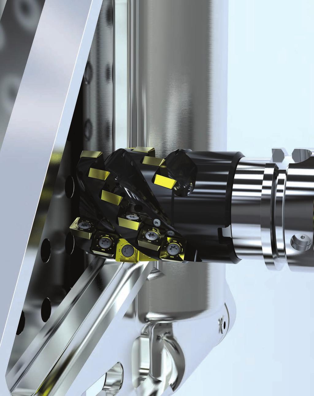
66 64

67 5505 Ball Nose Contour Milling Contour Milling of Mild s to High Temperature Superalloys 65


68 5505 Ball Nose Contour Mills 5505VX State of the Art Ball Nose Cutters Weldon 20mm 50mm Reinforced design for heavy machining High volume of chip cutting Excellent chip control and evacuation Cylindrical 16mm 32mm 5505VX Ball Nose Cutters are ideal for roughing and semi-finishing of profiles and complex contours in, Alloyed, Stainless, High Temperature Alloys and Cast Iron. One grade, one geometry does it all Helical insert design and rigid fixation for increased speeds and feeds Double edge insert is indexable for reduced inventory Slotting to full radius Modular 16mm 32mm Case History Material: Stainless 403 Cutter: 5505VX (25mm Cutter) Component: Turbine Blade Industry: Power Generation Insert Grade: SP6519 RPM: 2293 Cutting Speed Vc: 183 m/min Feed per Tooth fz: 0,28mm Feed Rate: 1285 mm/min Depth of cut ap: 3,18mm 40% Increase in Productivity 66


69 5505 Ball Nose Contour Mills 5505VX Heavy Duty Ball Nose Cutters Modular system absorbs vibrations under high length/diameter ratio Helical insert design for increased speeds & feeds Axial retention screw for added security One insert geometry for all materials Periphery ground insert generates a perfect radius size from the top to the center without facet during slotting Strong thick inserts ideal for medium to heavy roughing Indexable double edge insert 67


70 5505VX Ball Nose Milling Cutter d 1 L I 1 D Weldon Shank d 1 L Product Dimensions (mm) Spares Item Description D L/H l 1 d 1 ap max 5505VX Weldon Shank VX20WA020R FP3007T TP8 1, VX25WA025R D4010T T15 3, VX25WA025R D4010T T15 3, VX32WA032R D5013T T20 6, VX32WA032R D5013T T20 6, VX40WA040R D6014T T20 10, VX40WA040R D6014T T20 10, VX50WA050R F8017S KH , VX50WA050R F8017S KH , VX Cylindrical Shank VX16CA20/016R FP3006T TP8 1, VX20CA25/020R FP3007T TP8 1, VX25CA025R D4010T T15 3, VX25CA32/025R D4010T T15 3, VX32CA032R D5013T T20 6,00 No. of Teeth Screw Tightening Nm I 1 D Cylindrical Shank L d 1 M Product Dimensions (mm) Spares Item Description D L/H M d 1 ap max 5505VX Modular Head VX16SA016R M FP3006T TP8 1, VX20SA020R M FP3007T TP8 1, VX25SA025R M D4010T T15 3, VX32SA032R M D5013T T20 6,00 No. of Teeth Note: For cylindrical shank extensions in high density alloy with through coolant refer to page 74. Screw Tightening Nm D Modular Head Note: Do not remove the radial screw; this is a fixed location for the insert see page 72. a p Depth of Cut (ap) 68
71 5505VX Ball Nose Milling Cutter 5505VX Technical Information (mm) Product Item Description Facing Pitch Ramping Angle Dimensions Helical Hole min. - max. ap max Helical / Linear Max RPM VX20WA020R VX25WA025R VX25WA025R VX32WA032R VX32WA032R VX40WA040R VX40WA040R VX50WA050R VX50WA050R VX16CA20/016R VX20CA25/020R VX25CA025R VX25CA32/025R VX32CA032R VX16SA016R VX20SA020R VX25SA025R VX32SA032R Ramping 69
 l s r hm min 030737 XPNT16/160308.R-F SP6519-7,40 17,40 3,18 8,00 0,04 030743 XPNT20/20T306.R-F SP6519-9,00 20,85 3,97 10,00 0,04 030746 XPNT25/250408.")
72 5505VX Milling Inserts & Recommended Feeds XPNT-F Product Application & Material Dimensions (mm) Item Description Grade Roughing Semi-Finishing Finishing Depth of Cut (mm) ap max.* ae / ap max. ae / ap max. 10% of the cutter diameter - d (IC) l s r hm min XPNT16/ R-F SP6519-7,40 17,40 3,18 8,00 0, XPNT20/20T306.R-F SP6519-9,00 20,85 3,97 10,00 0, XPNT25/ R-F SP ,00 26,00 4,76 12,50 0, XPNT32/ R-F SP ,10 33,40 6,35 16,00 0, XPNT40/40T716.R-F SP ,00 41,84 7,95 20,00 0, XPNT50/50T716.R-F SP ,25 52,86 7,95 25,00 0,04 Machining Choice: 1 st Choice 2 nd Choice 3 rd Choice Material Guide Key descriptions found on page 73. * Note: ap max. is dependent on several insert sizes, see steel cutter page 84 for ap max. 5505VX Feeds f z (mm/tooth) Tool Diameter Geometry Grade Operation Unalloyed Alloyed Stainless Stainless Refractory PH Gray Iron Spheroidal- Ductile Iron Malleable Iron Aluminium & Alloys <16% Si 116 HBN Aluminium & Silicon >16% Si 92 HBN HTA Iron Based Alloys HTA Cobalt Based Alloys HTA Nickel Based Alloys HTA Titanium Based Alloys Hard >1400 N/mm 2 >415 HBN Chilled Cast Iron >1400 N/mm 2 >400 HBN Min. - Max. Min. - Max. Min. - Max. Min. - Max. Min. - Max. Min. - Max. Min. - Max. Min. - Max. Min. - Max. Min. - Max. Min. - Max. Min. - Max. Min. - Max. Min. - Max. Min. - Max. 16 R-F SP6519 Contouring 0,06-0,15 0,06-0,13 0,04-0,11 0,04-0,10 0,06-0,15 0,06-0,15 0,06-0, ,04-0,08 0,04-0,08 0,04-0,08 0,04-0, R-F SP6519 Contouring 0,06-0,17 0,06-0,15 0,04-0,13 0,04-0,12 0,06-0,17 0,06-0,17 0,06-0, ,04-0,10 0,04-0,10 0,04-0,10 0,04-0, R-F SP6519 Contouring 0,06-0,20 0,06-0,18 0,04-0,16 0,04-0,15 0,06-0,20 0,06-0,20 0,06-0, ,04-0,13 0,04-0,13 0,04-0,13 0,04-0, R-F SP6519 Contouring 0,06-0,22 0,06-0,20 0,04-0,18 0,04-0,17 0,06-0,22 0,06-0,22 0,06-0, ,04-0,15 0,04-0,15 0,04-0,15 0,04-0, R-F SP6519 Contouring 0,06-0,24 0,06-0,22 0,04-0,20 0,04-0,19 0,06-0,24 0,06-0,24 0,06-0, ,04-0,17 0,04-0,17 0,04-0,17 0,04-0, R-F SP6519 Contouring 0,06-0,27 0,06-0,25 0,04-0,23 0,04-0,22 0,06-0,27 0,06-0,27 0,06-0, ,04-0,20 0,04-0,20 0,04-0,20 0,04-0, Note: HTA = High Temperature Alloys Speed recommendations can be found on page
73 5505VX Recommended Speeds Speed v c (m/min) 5505VX Series Coolant Recommendation Recommended Possible Speed min. - max. PVD Standard ISO P M Grey GG-Ft K Cast Iron Spheroidal-Ductile GGG-FGS N Materials Unalloyed Alloyed Stainless PH Stainless Aluminium & Alloys Rm and Hardness <600 N/mm 2 <180 HBN <950 N/mm 2 <280 HBN N/mm HBN N/mm HBN N/mm HBN Austenitic + Ferritic 300 series Martensitic 400 series Refractory P.H. Malleable GTS - MN/MP Aluminium & Alloys < 16% Si 116 HBN Aluminium + Silicon > 16% Si 92 HBN SP Iron Based S High Temperature Alloys Cobalt Based Nickel Based Titanium Based H Hard Materials Hard >1400 N/mm 2 >415 HBN Chilled Cast Iron >1400 N/mm 2 > 400 HBN 71

 2 r 2 - r - a p r Please do not try to remove this screw.")
74 5505VX Technical Information 5505VX Technical Information Working Diameter: D e = 2 x r 2 - (r -a p ) 2 r De a p where: D e = Working Diameter r = Cutter radius a p = Axial Depth of Cut 5505VX Technical Information where: f z = Feed per tooth h m = Average chip thickness r = Insert radius a e = Radial Depth of Cut a p = Axial Depth of Cut Average chip thickness: h m h m = f z x ( ) 2 r 2 - r - a e r To find programmed feedrate: f z x ( ) 2 r 2 - r - a p r f z = ( ) 2 x r 2 - r - a e r h m ( ) 2 r 2 - r - a p r Please do not try to remove this screw. This screw is glued into the body to keep the inserts in the correct position. 72


75 5505 Ball Nose Contour Mills Case History Material: Titanium 6-4 Component: Valve Body Industry: Oil & Gas Cutter: 5505VX (25mm Cutter) Insert Grade: SP6519 RPM: 1469 Cutting Speed Vc: 115 m/min Feed per Tooth fz: 0,135mm Feed Rate: 395,3 mm/min Depth of cut ap: 1,5mm Helical Interpolation Doubled Productivity Ball Nose Geometry -F P P M M K S This geometry is a roughing ball nose fully ground insert for roughing and semi-finishing of all materials except Aluminium. This geometry is designed with chip grooves for better chip control. Ball Nose Grade SP6519 P P M M K S Coating Type: PVD, TiAlN The combination of a tough substrate with a new generation of TiAlN super nano coating, makes this new PVD coating virtually free of residual stress and extremely hard for unmatched performance. Primarily used in Stainless, High Temperature Alloys & Titanium with stable conditions. Also can be used in, Alloys and Cast Irons. Material Guide Key to Recommended Inserts Material Designation P Unalloyed s P Alloyed s M Stainless s M PH Stainless K Cast Irons N Aluminum & Alloys S High Temp. Alloys H Hard Materials 73

76 Cylindrical Shank Extensions for Modular Heads Anti-Vibration Tungsten Alloy with Through Coolant D 2 Product Dimensions (mm) Item Description L L 1 D 2 D D 1 M L L 1 D 1 D Shank Extension M-13-M8-CA ,50 M M-13-M8-CA ,50 M M-13-M8-CA ,50 M M-13-M8-CA ,50 M M-18-M10-CA ,50 M M-18-M10-CA ,50 M M-18-M10-CA ,50 M M-18-M10-CA ,50 M M-21-M12-CA ,50 M M-21-M12-CA ,50 M M-21-M12-CA ,50 M M-21-M12-CA ,50 M M-21-M12-CA ,50 M M-29-M16-CA ,00 M M-29-M16-CA ,00 M M-29-M16-CA ,00 M M-29-M16-CA ,00 M16 Note: Order example with cylindrical shank: M-13-M8-CA Cylindrical shank extensions can be used with all modular heads found in several product family series within this catalogue. These extensions have the industry standard of metric threads. Technical Advice M Modular adapter 13 Diameter in front of the modular shank (D) M8 Metric Thread (M) CA16 Cylindrical shank diameter 16mm with through coolant 90 Total length of the body 74

77 5720 Patented Profile Pocket Milling: Aluminium Taking extreme high speed aluminium machining to the highest level 75


78 5720 Profile Pocket Milling: Aluminium 5720 Patented Series High Speed Aluminium Cutters 5720 Up to RPM Cylindrical 25mm 32mm Shell 40mm 80mm Extreme Metal Removal to fit your application Especially designed for machining pockets and profiles on Aluminium and Aluminium Alloys The 5720 is designed, manufactured and tested in accordance with EN ISO 15641:2001 to ensure maximum stability in high speed applications Each features internal coolant allowing better chip evacuation and higher feed rates The pockets are reinforced to allow for heavy feeding and safe ramping during machining Excellent tools for thin-walled machining HSK specials available upon request Cylindrical Shank and special HSK Integral Shanks are balanced to RPM for diameters up to 50mm. Diameters larger than 50mm are balanced to RPM inserts: 12 different radii are available, each with the same cutting depth capacity of 16mm Modular 25mm 32mm 76

79 5720 Profile Pocket Milling: Aluminium 5720 Patented Series Extreme High Speed Aluminium Cutters Cylindrical Shank designed and balanced to G6.3 at RPM Capable of operating up to RPM Flute engineered for maximum chip evacuation Excellent tool for thinwalled machining Internal coolant for maximum chip evacuation Inserts with different radii are held without losing any gauge height of the cutter length 12 different insert radii are available, each with a 16mm cutting depth 77


80 5720VZ16 Profiling / Pocketing Milling Cutters d 1 H L I 1 D Cylindrical Shank d 1 Product Dimensions (mm) Spares Item Description D L/H l1 d1 ap max 5720VZ16 Cylindrical Shank - Coarse and Medium Pitch VZ16CA025Z2R Facet to 6, DP5009A TP20 6, VZ16CA032Z2R Facet to 6, DP5009A TP20 6, VZ16CA032Z3R Facet to 6, DP5009A TP20 6, VZ16 Shell Mill Fixation - Coarse and Medium Pitch VZ16-A040Z03R Facet to 6, DP5009A TP20 6, VZ16-A050Z03R Facet to 6, DP5009A TP20 6, VZ16-A050Z04R Facet to 6, DP5009A TP20 6, VZ16-A063Z05R Facet to 6, DP5009A TP20 6, VZ16-A063Z04R Facet to 6, DP5009A TP20 6, VZ16-A080Z04R Facet to 6, DP5009A TP20 6, VZ16-A080Z05R Facet to 6, DP5009A TP20 6,00 No. of Teeth Insert radius range * It is important to change the screw each time the insert is changed to ensure the highest security. A dynamometric key and the right torque value are important. See above for the correct torque information. Screw Tightening Nm* D Shell Mill Fixation d 1 M Product Dimensions (mm) Spares Item Description D L/H M d1 ap max 5720VZ16 Modular Head - Coarse and Medium Pitch VZ16SA025Z2R M12 12, Facet to 6, DP5009A TP20 6, VZ16SA032Z2R M Facet to 6, DP5009A TP20 6, VZ16SA032Z3R M Facet to 6, DP5009A TP20 6,00 No. of Teeth Insert radius range Screw Tightening Nm* L * It is important to change the screw each time the insert is changed to ensure the highest security. A dynamometric key and the right torque value are important. See above for the correct torque information. Note: For cylindrical shank extensions in high density alloy with through coolant refer to page 74. D Modular Head a p Depth of Cut (ap) 78
81 5720VZ16 Profiling / Pocketing Milling Cutters 5720VZ Technical Information (mm) Product Item Description Facing Pitch Ramping Angle Dimensions Helical Hole min. - max. ap max Helical / Linear Max RPM VZ16CA025Z2R * 29,5 48,0 4, VZ16CA032Z2R * 43,5 62,0 4, VZ16CA032Z3R * 43,5 62,0 4, VZ16-A040Z3R * 59,5 78,0 4, VZ16-A050Z03R * 79,5 98,0 4, VZ16-A050Z4R * 79,5 98,0 4, VZ16-A063Z05R * 105,5 124,0 4, VZ16-A063Z4R * 105,5 124,0 4, VZ16-A080Z04R * 139,5 158,0 4, VZ16-A080Z05R * 139,5 158,0 4, VZ16SA025Z2R * 29,5 48,0 4, VZ16SA032Z2R * 43,5 62,0 4, VZ16SA032Z3R * 43,5 62,0 4, * Max. ramping angle for insert is calculated with facet Ramping Flat Facing Pitch Helical Interpolation Find the different ramping angles for all available insert radii on technical information page 81. Radial depth of cut 0,20mm up to full cutter diameter. These tools have been designed, manufactured and tested in accordance with EN ISO standard 15641:2001. These tools are stocked without an electronic chip. Note: If using a insert with radius, then the facing pitch for the 5702VZ cutter is equal to the cutting diameter (D) minus 2 x chosen radius. Cylindrical Shanks or Special HSK Integral Shanks are designed and balanced to G6.3 at 30,000 RPM for diameters 50mm and below. Diameters larger then 50mm are balanced to G6.3 at 24,000 rpm. Cylindrical Shank tools mounted in a shrink fit holder or any other mill chuck holder + inserts + screws must be re-inspected for balance as an assembly by the end user when at or exceeding 8,000 rpm. End user must balance the assembly to a G6.3 value minimum. Shell Mills and Modular Heads are not balanced. These tools must be re-inspected for balance as an assembly, cutter + adapter + inserts + screws by the end user when at or exceeding 8,000 rpm. End user must balance the assembly to a G6.3 value minimum. Additional Balancing and Torque values can be found in the technical section pages

82 5720VZ16 Milling Inserts, Recommended Feeds & Speeds ZDET l Product Application & Material Dimensions (mm) Roughing Semi-Finishing Finishing d r s Item Description Grade Depth of Cut (mm) ap max. ap min. - max. ap min. - max. 16* 1,00-5,00 0,20-1,00 d (IC) l s r hm min ZDET16M5PDFR-721 GH1 11,30 22,92 5,00 Facet 0, ZDET16M504FR-721 GH1 11,30 22,92 5,00 0,40 0, ZDET16M508FR-721 GH1 11,30 22,92 5,00 0,80 0, ZDET16M512FR-721 GH1 11,30 22,92 5,00 1,20 0, ZDET16M516FR-721 GH1 11,30 22,92 5,00 1,60 0, ZDET16M520FR-721 GH1 11,30 22,92 5,00 2,00 0, ZDET16M525FR-721 GH1 11,30 22,92 5,00 2,50 0, ZDET16M530FR-721 GH1 11,30 22,92 5,00 3,00 0, ZDET16M532FR-721 GH1 11,30 22,92 5,00 3,20 0, ZDET16M540FR-721 GH1 11,30 22,92 5,00 4,00 0, ZDET16M550FR-721 GH1 11,30 22,92 5,00 5,00 0, ZDET16M560FR-721 GH1 11,30 22,92 5,00 6,00 0,02 Machining Choice: 1 st Choice 2 nd Choice 3 rd Choice Material Guide Key descriptions found on page 84. * Max. possible ap of 16mm and ae the full diameter (depending on the application). * For Slotting applications with 5720VZ16 series please see recommendations for maximum ap on page VZ Feeds f z (mm/tooth) Speed v c (m/min) Size Geometry Grade Operation Aluminium & Alloys <16% Si 116 HBN Min. - Max. Aluminium & Silicon >16% Si 92 HBN Min. - Max. 14mm FR-721 GH1 Profile/ Pocketing 0,02-0,25 0,02-0, VZ Series Coolant Recommendation Recommended Possible K10-K20/C3 - C2 ISO / ANSI Speed min. - max. Uncoated Micrograin ISO Materials Rm and Hardness GH1 N Aluminium & Alloys Aluminium & Alloys < 16% Si 116 HBN Aluminium + Silicon > 16% Si 92 HBN
83 5720VZ16 Technical Information Calculation of the average chip thickness in relation with the a e (Radial Engagement) if a e is less than 50% of Dia. Formula: Programme Feed Rate (f z ) f z = h m x d a e h m = Average chip thickness a e = Radial engagement f z = Feed per tooth d = Cutter diameter Formula: Average Chip Thickness (h m ) h a m = f z x e d 5720VZ16 Ramp Angle Insert ZDET16M5 FR-721 (Radius mm) Cutter Dia. (mm) PDFR to R1,20 R1,60 R2,00 R2,50 R3,00 R3,20 R4,00 R5,00 R6,00 25, , , , , Possible Max. a p Slotting Chart for maxium a p when slotting with 5720VZ16 series Diameter (mm) No. of Inserts a p max (mm) , , , , , , , , , ,00 Possible Metal Removal Calculated with RPM Cutter dia. Z Qcm 3 /min ap max in connection with: The cutter diameter, rigidity of the cutter, rigidity of the machine and the size of the flute. The chart above shows total metal removal capacity (based on 24,000 RPM) by cutter diameter and number of teeth. The maximum RPM is engraved on all cutter bodies. 81
84 5702VZD & 5720VZ Technical Information Machinability by Materials (Aluminium) Alloy Group Al Al-Cu min - H D A ~0.20 Si+Fe1.0max min - H14 90 D A ~ remaining - T3 310 A A ~ ~ ~ ~ remaining - T6 430 B A ~ ~ ~ ~ remaining - T4 390 B A ~ ~ ~ remaining - T4 465 B A ~ ~ remaining Ni1.7~2.3 T B B ~ ~ ~ remaining - A A , ,25 Cooking utensils. Al-Mn ~ ~ remaining - H D B ,2 Chemical equipment. Al-Si ~ ~ ~ remaining Ni0.5~1.3 T6 379 B D Pistons ,18 Al-Mg Al-Mg-Si Al-Zn Alloy Designation CHEMICAL COMPOSITION LIMITS (WT%) Cu Si Fe Mn Mg Zn Cr Ti Pb Bi Al Others ~ ~ remaining - H C A ~ ~ ~ remaining - H C A ~ ~ ~ remaining - H C A ~ ~ ~ remaining - H C A ~ ~ ~ ~ remaining - T6 300 C B ~ ~ remaining - T5 200 C B ~ ~ ~ ~ remaining - T6 379 C C ~ ~ ~ remaining - T6 C C ~ ~ ~ ~ remaining - T9 400 B B ~ ~ ~ remaining - T6 310 D C ~ ~ remaining - T6 241 C B ~ ~ ~ ~ remaining - O B A ~ ~ remaining Zr0.05~0.25 T5 400 B A ~ ~ ~ remaining Zr0.08~0.15 T B A ~ ~ ~ ~ remaining - T6 570 B A ~ ~ ~ ~ remaining - T6 600 B A ~ ~ ~ ~ remaining - T B A H34 H32 H116 Typical tremper Rm (Mpa) Machinability Chip formation Machinability Typical Applications Chemical equipment Sheet metal work Coiled tube Screw machine products. Tuck frame. Aircraft structure. Jet engine impellers. Aircraft engine cylinder heads. Architectural. Cable Sheeting. Welded pressure vessels. Hydraulic tubes. Transportation equipment. Heavy duty structure. Furniture. Architectural. Heavy duty welded structure. Pipeline. Heat Sink. v c m/min f z mm/z min. - max. max , ,2 High strength structure ,25 Aircraft structure. Bat. Machinability A EXCELLENT B GOOD-TO-EXCELLENT C GOOD D NOT GOOD V c = π x D x n / 1000 m/min = mm x RPM D: Tool diameter, N: RPM, V c : Cutting speed, π = Choose a cutting speed in the range of values, compatible with the cutter max rotation capacity (engraved on the body) and your spindle stability. 82
85 5702VZD & 5720VZ Technical Information Recommendations for High Speed Machining at 8,000 rpm or above. Check spindle condition: Runout Balancing Clamping of the attachment in traction Marking and cleanliness Check that the tool is suitable for the required use. Inserts must be locked positively in the pocket and secured using the torx screw provided. The screw must be torqued to the correct value as indicated in our charts on the steel product page 78. For security use a new screw each time. Check the balancing of the assembled tool cutter body, inserts and attachment. Before start up, note the maximum RPM engraved on the tool or in our technical documents. The maximum RPM is linked to a precise balancing value. Ensure that the field of application of the tool shown in our technical documents and technological parameters is observed: The Cutter Nomenclature Code: Example: 5702VZD14CA020R = Stellram Product Family V = Screw fixation Z = Insert shape (parallelogram) D = ISO insert clearance (D = 15 ) 14 = Insert edge length (mm) C = Plain straight shank (No flats) A = Through the tool coolant 020 = Cutting diameter (mm) R = Right hand tool 58 = Reach of tool in mm -2 = Maximum value of the insert radius in 1/10mm increments This tool must only be used for the following applications: Face milling, shoulder milling, slotting and pocketing. Cylindrical shanks & HSK shanks (special): 5702VZD14 and 5720VZ16 are designed and balanced to G6.3 at 30,000 rpm for diameters 50mm and below. Diameters larger then 50mm are balanced to G6.3 at 24,000 rpm. Cylindrical shank tools mounted in a shrink fit holder or any other mill chuck holder + inserts + screws must be re-inspected for balance by the end user when exceeding 8,000 rpm. End user must balance the assembly to a G6.3 value minimum. a e (mm) a p (mm) f z (mm/tooth) n (rpm) width of cut, lateral engagement (radial) Axial depth of cut Feed per tooth RPM Shell Mills and Modular Heads: 5720VZ16 Shell Mills and Modular Heads are not balanced. These tools must be re-inspected for balance as an assembly, cutter + adapter + inserts + screws by the end user when at or exceeding 8,000 rpm. End user must balance the assembly to a G6.3 value minimum. Stellram cannot accept responsibility for misuse of this product: Non observance of the above instructions Machine without casing Incorrect clamping of workpieces No safety device on the machine Any misuse or incorrect clamping Balancing requires removing some material by drilling or milling operations. To avoid making modular heads weaker, limit these operations by avoiding high rpm. For each new modular head added to the same extension, re-balance the assembly. For each new Shell Mill installed on the same toolholder, re-balance the assembly. The optimum rotation must be determined by condition of the spindle. The spindle must be rigid to run at these higher RPMs. Under no circumstances must any attempt be made to repair this tool. The only permitted maintenance is the indexing or replacement of the inserts. Use a new screw for each insert replacement. When assembling the cutter to a shrink fit holder, the maximum protrusion can not exceed 10% of the reach of tool. Tighten the Modular Head to the Extension, with lubricant, apply the torque value of: Thread sizes (mm) Torque Values Nm M6 10 M8 30 M10 50 M12 80 M Tighten the bolt between the shell mill and tool holder, with lubricant apply the torque value of: Thread sizes (mm) Cutter Bore Size (mm) Torque Values Nm M M M M M M


86 5702VZD & 5720VZ Technical Information 5720 Case History Material: Aluminium 2024 Cutter: 5720VZ (32mm Cutter) Component: Seat Support Industry Segment: Aerospace Insert Grade: GH1 Spindle Speed: 17,491 RPM Cutting Speed Vc: 1758 m/min Feed per Tooth fz: 0,25mm Feed rate: 8745 mm/min Depth of Cut: 2,5mm Result: 400% Increase in Productivity 5720 High Speed Geometry -721 N This extreme high positive geometry is highly suitable for machining Aluminium Alloys, Copper and Brass. This geometry is periphery ground with a pressed, polished top rake face reducing built up edge. Especially qualified when machining thin-walled components. High Speed Grade GH1 N Uncoated, Micrograin This micrograin grade is designed for use on Aluminium Alloys, Copper, Brass and Kevlar etc. The grade GH1 works well with or without coolant with low cutting pressure at high speeds due to sharp cutting edge. Material Guide Key to Recommended Inserts Material Designation P Unalloyed s P Alloyed s M Stainless s M PH Stainless K Cast Irons N Aluminum & Alloys S High Temp. Alloys H Hard Materials 84

87 5702 High Speed Aluminium Cutters Outstanding performance in a 20mm cutter 85
88 5702 High Speed Aluminium Cutter 5702 Series High Speed Aluminium Cutters 5702 Up to RPM Cylindrical 20mm Extreme Metal Removal to fit your application Especially designed for machining pockets and profiles on Aluminium and Aluminium Alloys Desiged, manufactured and tested in accordance with EN ISO 15641:2001 to ensure maximum stability in high speed applications Through-tool coolant allowing better chip evacuation and higher feed rates Pockets are reinforced to allow for heavy feeding and safe ramping during machining Excellent tools for thin-walled machining HSK specials available upon request 12mm depth of cut 5 radii available -701 fully ground geometry ideal for high speed Aluminium milling Balanced to RPM 5702 Case History Material: Aluminium Alloy 7175 Component: Airframe Industry Segment: Aerospace Tool: 5702VZD (20mm Cutter) Insert Grade: GH2 Cutting Speed Vc: 754 m/min Spindle Speed: RPM Feed per Tooth fz: 0,25mm Feedrate: 6000 mm/min Precision inserts provide excellent results in thin-wall machining applications while yielding superior surface finishes 86


89 5702 High Speed Aluminium Cutter 5702 Precision High Speed Aluminium Cutter Cylindrical Shank designed and balanced to G6.3 at RPM Flute engineered for maximum chip evacuation Excellent tool for thin-walled machining Capable of operating up to RPM Fully ground uncoated micrograin inserts can be run wet or dry 5 different insert radii are available, each with a 12mm cutting depth 5702 Geometry -701 N This extreme high positive geometry is highly suitable for machining Aluminium Alloys, Copper and Brass. The -701 geometry is precision ground and gives excellent performance when machining thin-walled components Grade GH1 N Uncoated, Micrograin This micrograin grade is designed for use on Aluminium Alloys, Copper, Brass and Kevlar, etc. The grade GH1 works well with or without coolant with low cutting pressure at high speeds due to sharp cutting edge. Material Guide Key to Recommended Inserts Material Designation P Unalloyed s P Alloyed s M Stainless s M PH Stainless K Cast Irons N Aluminum & Alloys S High Temp. Alloys H Hard Materials 87
Kennametal Inc Technology Way Latrobe, PA USA. Tel: (United States and Canada)
") C WORLD HEADQUARTERS Kennametal Inc. 1600 Technology Way Latrobe, PA 15650 USA Tel: 800.446.7738 (United States and Canada) E-mail: ftmill.service@kennametal.com EUROPEAN HEADQUARTERS Kennametal Europe
C WORLD HEADQUARTERS Kennametal Inc. 1600 Technology Way Latrobe, PA 15650 USA Tel: 800.446.7738 (United States and Canada) E-mail: ftmill.service@kennametal.com EUROPEAN HEADQUARTERS Kennametal Europe
UTTING TOOLS. Stellram Cutting Tools NEW HIGH FEED 7793VX012 DOUBLE SIDED INSERT MILLING CUTTER SYSTEM
 UTTING TOOLS Stellram Cutting Tools NEW HIGH FEED 7793VX012 DOUBLE SIDED INSERT MILLING CUTTER SYSTEM 7793 VXO12 Features & Benefits Silver satin plated surface & Improved heat treatment Improved body
5315VA Series. Long Edge Milling Cutter
 5315VA Series Long Edge Milling Cutter Profiling / Slotting LONG EDGE MILLING CUTTER The 5315VA family is the long edge cutter version of our versatile 7690VA shoulder milling series. This 5315VA series
5230VS Series. Chevron Long Edge Milling Cutter (Porcupine)
") 5230VS Series Chevron Long Edge Milling (Porcupine) Shoulder / Profiling / Slotting HIGH PERFORMANCE LONG EDGE MILLING CUTTERS The Stellram 5230VS09 and VS12 Series is perfectly quali ed for pro ling and
5230VS Series Chevron Long Edge Milling (Porcupine) Shoulder / Profiling / Slotting HIGH PERFORMANCE LONG EDGE MILLING CUTTERS The Stellram 5230VS09 and VS12 Series is perfectly quali ed for pro ling and
UTTING TOOLS. Stellram Cutting Tools. 7713VR Round Insert Milling Cutter with Indexation. Inch.
 UTTING TOOLS Stellram Cutting Tools 7713VR Round Insert Milling Cutter with Indexation Inch 7713VR Series Copy / Contour Milling Cutter ROUN INSERT MILLING CUTTER WITH INEXATION The 7713VR is our newest
7700VR Series Copy Milling Cutter
 7700VR Series Copy Milling Cutter Facing Copy / 3 Ramping Spiral / Circular Helical Interpolation Helical Interpolation with Bore Hole Pocketing ROUN INSERT MIING CUTTERS WITHOUT INEXATION The 7700VR series
7220VM Series. Disk Mill Cartridge Cutters
 Series Disk Mill Cutters Slotting / Shoulder DISK MILL CARTRIDGE CUTTERS 7220VM Disk Mill Cutter series with adjustable cartridges are designed for machining deep slots or side shoulder milling operations.
milling products For Power Generation and Aerospace Applications
 Turbine Blade achining Cutting Tool Systems Solutions for Difficult-To-achine aterials milling products For Power Generation and Aerospace Applications 1 Solutions For Difficult-To-achine aterials Stellram
80_0VA90-_R-16 Series
 Series Cartrige Shouler Milling Cutter Facing Slotting 90 CARTRIDGE SHOULDER MILLING ASSEMBLIES Applications: 80_0VA90 cutter series are assemble with cartriges for AP..16 milling inserts for face an shouler
Efficient Machining Solutions in Titanium Alloys. David J Wills
 Efficient Machining Solutions in Titanium Alloys David J Wills Acknowledgement The following presentation is a result of collaboration of ATI s metallurgists, scientists and engineers in providing an effective
TURNING. Stellram Cutting Tool Products
 TURNING Stellram Cutting Tool Products ATIstellram.com ATImetals.com Turning Machining Solutions for Mission Critical Metallics Increase productivity and reduce tooling costs in today s most challenging
The Art and Science of Milling Titanium.
 Tom Hofmann Global Product Manager - Milling ATI Stellram The Art and Science of Milling Titanium. ATI Stellram, a business unit of ATI Engineered Products, and an Allegheny Technologies company. Increasingly
Expansion of the HELIDO 690 LINE with Tools Carrying 10 mm Edged Inserts
 MILLING JANUARY Page 1 / 8 Expansion of the HELIDO 690 LINE with Tools Carrying 10 mm Edged Inserts JANUARY Page 2 / 8 Highlights Milling cutters carrying a double-sided triangular insert with six 10 mm
Applications. Plunging - Z Axis Milling* 3D / Copy Milling* Facing. Slotting / Shoulder Milling. Spiral / Circular. Ramping
 All TyCarb HF tools can easily be converted from High Feed to Degree Square Shoulder Simply switch insert styles from XDMT / XDMW to SDMT Less cost and inventory to manage Applications 3D / Copy Milling*
The best of both worlds
 The best of both worlds CoroMill 210 the ultimate roughing cutter for modern machining techniques Use CoroMill 210 for plunge milling to mill away large volumes of metal or for high feed milling of flat
All TyCarb HF tools can easily be converted from High Feed to 90 Degree Square Shoulder Simply switch insert styles from
 All TyCarb HF tools can easily be converted from High Feed to Degree Square Shoulder Simply switch insert styles from XDMT / XDMW to SDMT Less cost and inventory to manage Applications D / Copy Milling*
SQUARE T4-08 & T4-12
 SQUARE T4-08 & T4-12 SQUARE T4-08 & T4-12 DEFINITION Square T4 Definition Definition of Square T4-08/T4-12 Square = Square shoulder cutter T4 = Tangentially mounted inserts with 4 edges/insert 08/12 =
MFH Micro. Micro Dia. Cutter for High Feed Machining. Low Resistance and Durable Against Chatter for Highly Efficient Machining
 Micro Diameter High Feed Mills Micro Dia. Cutter for High Feed Machining Low Resistance and Durable Against Chatter for Highly Efficient Machining Shortens Rough Machining Times Replaces Solid End Mills
DHC. Differential Helix Cutter
 DHC Differential Helix Cutter Universal Short and Long End Mills for the Highest Productivity in Roughing and Finishing Applications (Standard & with Corner Radius) 2 x d 1 x d DHC (Differential Helix
RD-SAF Face milling and profiling cutter with positive round inserts
 RD-SAF Cutter program, RD 2, RD 6, RD 20 ødm (CM) m l 2 ødm m B ød c ød c Morse taper Arbor mounting D c D 3 Max. dm m l 2 l 3 B F Z Nb of inserts Coolant channels Morse taper RD-2/032-03-CM3-080 20.00
The new force in machining.
 Product handbook Milling _ SILVER, BLACK, STRONG The new force in machining. Yesterday, it was machining. Today, it s tigering. Cutting tool materials with the Tiger tec technology brand are setting the
Jongen UNI-MILL VHC milling cutter
 Jongen Werkzeugtechnik Jongen UNI-MILL VHC milling cutter Trochoidal milling at the highest level Jongen UNI-MILL VHC milling cutter Static and dynamic "trochoidal milling" is a combination of circular
SQUARE 6 SQUARE SHOULDER MILLING GETS EVEN SMALLER
 SQUARE 6 SQUARE SHOULDER MILLING GETS EVEN SMALLER SQUARE 6 PRODUCTIVITY WI COMPETITIVE EDGES This latest square-shoulder innovation is a result of our commitment to you, and a desire to engineer tooling
4 Flute All Purpose. duramill.com. for steels, stainless steels and high-temp alloys. roughing, slotting, pocketing & ramping applications
 4 Flute All Purpose for steels, stainless steels and high-temp alloys roughing, slotting, pocketing & ramping applications duramill.com 2 4 Flute AP The new WhisperKut GEN2 4 Flute AP has been engineered
TURBINE BLADE MACHINING
 TURBINE BLADE MACHINING ATI Stellram tooling systems for all your tooling requirements. Turbine Blade Machining ATI Stellram s tooling systems are designed and manufactured for machining high performance
Jongen Werkzeugtechnik GmbH
 STEP MILLING Type B22 Jongen Werkzeugtechnik GmbH Siemensring 11 D-47877 Willich Germany Phone: 0049 2154 9285 2900 Fax: 0049 2154 9285 9 2900 www.jongen.de Email: export@jongen.de THE TOOL Especially
Technical information / Clamping system Wedge clamping This classic positive insert clamping system allows the use of all models presenting this geome
 Technical information Applications Code key M.02 M.03 M.03 M.04 Cutting data M.06 Tooling rilling & boring CANELA M.01 Technical information / Clamping system Wedge clamping This classic positive insert
NPA. New Small Diameter Fast Feed Tools Carrying Inserts with Four Cutting Edges. New Product Announcement INCH MARCH 2018.
 NPA New Product Announcement New Small Diameter Fast Feed Tools Carrying Inserts with Four Cutting Edges Page 1 / 7 Page 2 / 7 Highlights ISCAR is introducing new small diameter Fast Feed tools carrying
Small but Powerful Positive Insert with Dovetail Design
 1/9 Small but Powerful Positive Insert with ovetail esign 2/9 Small but Powerful Positive Insert with ovetail esign TaeguTec is proud to introduce a brand new product line to its popular CHASEMI family.
MaxiMill HFC 'Feed matters', rapid milling
 MaxiMill HFC 'Feed matters', rapid milling EN CERATIZIT - secrets of success Secrets of success CERATIZIT is your partner for exceptional hard material solutions. Hard materials and tools from CERATIZIT
TOOLS NEWS B055E Update. Multi-functional Indexable Cutter APX3000/4000. A new generation of high performance cutters.
 TOOLS NEWS 2014.01 Update B055E Multi-functional Indexable Cutter APX3000/4000 A new generation of high performance cutters. Multi-functional milling Cutter APX3000/4000 Multi functional The APX is highly
POW R PATH enduro STREAKERS POW R FEED OMEGA-6 INCONEX
 Power. Precision. Performance. POW R PATH enduro STREAKERS POW R FEED OMEGA-6 INCONEX M E T A L M O R P H O S I S THE NEW FRONTIER OF ADVANCED END MILLS M E T A L M O R P H O S I S THE NEW FRONTIER OF
Power Generation Materials Require New Approaches In Machining
 Power Generation Materials Require New Approaches In Machining Machining the alloys used in today s power generation applications present major challenges to manufacturers. New materials and new design
A New Positive Multi Corners Milling Line
 1/9 A New Positive ulti Corners illing Line 2/9 With the increasing popularity of small machining centers, TaeguTec is pleased to launch a new single-sided line of positive seven corners insert that generates
MaxiMill HFC 'Feed matters', rapid milling
 MaxiMill HFC 'Feed matters', rapid milling CERATIZIT - secrets of success Secrets of success CERATIZIT is your partner for exceptional hard material solutions. Hard materials and tools from CERATIZIT -
Jongen Werkzeugtechnik. Working depth. Drilling by JONGEN. 3 x D. BP 04 to 12
 Jongen Werkzeugtechnik Working depth 3 x D Drilling by JONGEN BP 04 to 12 THE TOOL New at Jongen: universally applicable high-performance drill for use on lathes and milling centers. It offers the highest
INCH. Revised. ADKT 1505R8T-FF a Combination of and
 Page 1/7 MAY 2007 Revised ADKT 1505R8T-FF a Combination of and ISCAR is expanding the application range of the HELIMILL tools by a new 15 mm insert with a FEEDMILL configuration. The new ADKT 1505R8T-FF
New XEVT Line for Excellence in Aluminum Machining
 1/14 New XEVT ine for Excellence in Aluminum Machining 2/14 To ensure excellence in aluminum machining across all industries, TaeguTec s CHASEAU line now comes in two new offerings: the XEVT 16 which is
TAKE IT ON WITH TITANOX
 YU-TP8 BEST VALUE IN THE WORLD OF CUTTING TOOLS FOR TITANIUM, STAINLESS STEEL AND ALLOY STEELS : TOUGH MATERIALS? TAKE IT ON WITH TITANOX INDUSTRY-LEADING SOLID CARBIDE END MILLS HIGH-PERFORMANCE MACHINING
MaxiMill HFC 'Feed matters', rapid milling
 MaxiMill HFC 'Feed matters', rapid milling CERATIZIT - secrets of success Secrets of success CERATIZIT is your partner for exceptional hard material solutions. Hard materials and tools from CERATIZIT -
TOOL NEWS B055A Update. Multi-functional Indexable Cutter APX3000/4000. Holder Expansion. A new generation of high performance cutters.
 TOOL NEWS 2015.11 Update Multi-functional Indexable Cutter APX3000/4000 B055A Holder Expansion A new generation of high performance cutters. Multi-functional Indexable Cutter APX3000/4000 Multi functional
Price/1. Price/1. Price/1. 1/ 8 3/ 8 1 1/ 2 1/ 8 10g -4580K / 4 3/ 4 2 1/ 2 1/ 4 30g -4660K / / 2 3/ 8 60g -4740K 291.
 2 Flute For optimum performance and maximum swarf removal when plunging, slotting and routing in most materials including brass, aluminium, non-ferrous and other soft materials. Manufactured to USCTi Standards.
For Gear, Spline & Rack Manufacturing
 For Gear, Spline & Rack Manufacturing METR Advanced Technologies for Gear, Spline and Rack Manufacturing See it in action The VARDEX Gear Milling Concept Advanced milling tools with multi-flute indexable
High-Performance Solid Carbide End Mills Hard Materials
 High-Performance Solid Carbide Hard Materials..................................A39 A50 Series 7S05 Lists 7S05 7S15 7S25 Vision Plus..........................A40 Series 7S5F Vision Plus...........................A41
Made in Germany. SELECTION Milling 2017 valid until Economical Tools for Milling
 Made in Germany SELECTIO Milling 2017 valid unti8.02.2018 Economical Tools for Milling EMUGE-FRAKE Industry Solutions Economical high performance cutting tools for the demanding industries of today and
WINTER / SPRING. Special Offers for Turning, Milling, and Drilling Products. VALID THROUGH June 30 th, CA5-SERIES Turning Inserts 9
 2015 WINTER / SPRING P R O M O P A C K Special Offers for Turning, Milling, and Drilling Products F E A T U R I N G Turning s 9 MFH-RAPTOR High Feed Mills 10-11 M-FOUR (MEW) 90 Milling Cutters 12-13 45
Carbide Modular Shrink System
 Carbide Modular Shrink System Millstar s Carbide Modular Shrink System offers versatility, strength and accuracy. The carbide shank offers strength and rigidity and the shrink tolerances offer better accuracy
Milling tools made by JONGEN! C10 FP 124. Face Milling
 Milling tools made by JONGEN! Face Milling C10 FP 124 THE TOOL Especially efficient face milling cutter for the roughing and finishing machining Axial depth of cut max. 5 mm, with 8 effective cutting edges
High Performance Catalog
 High Performance Catalog www.sgstool.com As a technological leader, SGS Tool Company is committed to provide you with leading-edge, high-performance products. We address the complexities of High-Speed
Solid Carbide Taps.
 Solid Carbide Taps www.vergnano.com VERGNANO CARBIDE TAPS The use of carbide tools has increased significantly in the last few years. Nowadays turning, drilling and milling operations are done, for the
MaxiMill the 90 shoulder and slot milling system
 MaxiMill 211 - the 90 shoulder and slot milling system CERATIZIT - the parent companies Headquarters and parent company in MAMER / Luxembourg Parent company in REUTTE / Austria Hard material matters -
WINTER / SPRING. Special Offers for Turning, Milling, and Drilling Products. VALID THROUGH June 30 th, CA5-SERIES Turning Inserts 9
 2015 WINTER / SPRING P R O M O P A C K Special Offers for Turning, Milling, and Drilling Products MFH-RAPTOR M-FOUR (MEW) F E A T U R I N G Turning s 9 MFH-RAPTOR High Feed Mills 10-11 M-FOUR (MEW) 90
NEW HIGH FEED MILLING CUTTER. No. 143 E / version 2 HIGH FEED MILLING CUTTER 15G1F/5G_F
 NEW HIGH FEED MILLING CUTTER 15G1F/5G_F HIGH FEED MILLING CUTTER Very smooth cutting insert geometry -edged inserts different insert geometries in 6 different carbide grades Available as shell-type and
PERFORMANCE! PRODUCTIVITY! ECONOMY!
 Cutter Style: DG5P (High Density) DG6P (Low Density) 1DG1P Insert Series: UNEU1307R-M UNEU1307R-MM UNEU1307R-MR Grades: IN2505 IN2504 IN2530 IN2035 IN7035 Applications: Die & Mold Aerospace General Purpose
для размещения заказа - VG-Cut Deep Grooving, Threading and Parting Off METRIC
 Deep Grooving, Threading and Parting Off METIC Deep Grooving, Threading and Parting Off Complete ange of Solutions for External Turning Applications VAGUS Ltd., the leading supplier of premium thread turning
SUMMARY TECHNICAL INSTRUCTIONS. Technical Information. Geometries and feed rates. Cutting data. Carbide grades for grooving and parting off
 SUMMARY TECHNICAL INSTRUCTIONS Technical Information Grooving / Side turning Face grooving Profiling Threading Parting off Page 2-5 6 7 8-9 10-11 Geometries and feed rates Cutting data Inserts type 217
NEW HIGH FEED MILLING CUTTER HIGH FEED MILLING CUTTER 15G1F/5G_F
 NEW HIGH FEED MILLING CUTTER 15G1F/5G_F HIGH FEED MILLING CUTTER Very smooth cutting insert geometry -edged inserts 2 different insert geometries in 3 different carbide grades Available as shell-type and
For Gear, Spline & Rack Manufacturing
 For Gear, Spline & Rack Manufacturing METR Advanced Technologies for Gear, Spline and Rack Manufacturing See it in action The VARDEX Gear Milling Concept Advanced milling tools with multi-flute indexable
Ferritic/martensitic cast steel. Stainless steel Austenitic
 Machining Data for Threading ISO Material Condition Tensile Strength [N/mm ] Hardness HB Material < 0. %C Annealed 0 1 1 No. Non-alloy steel and cast steel, free cutting steel >= 0. %C Annealed 0 190
DOUBLE OCTOMILL ECONOMICAL FACE MILLING FAMILY FOR LARGE AND SMALL MACHINES
 DOUBLE OCTOMILL ECONOMICAL FACE MILLING FAMILY FOR LARGE AND SMALL MACHINES DOUBLE OCTOMILL BOOST YOUR PRODU TWO SIZES Are now available to meet a wide variety of face milling challenges. The Double Octo
3F Turning Geometry. Product Offering
 F Turning Geometry The new F geometry is a semifinishing and finishing geometry that is ideal for machining high accuracy components with thin wall sections such as turbine discs and fan discs found in
Keeping the Customer First. Tungaloy Catalogue TE0707-E2. Cutting Tools.
 Keeping the Customer First Tungaloy Catalogue TE0707-E2 2007 Cutting Tools www.tungaloy-eu.com Selection Guides List of... 410 Selection Guides... 412 Specifications Solid Carbide s For High Speed Deep
SOLID END MILLS CATALOGUE & TECHNICAL GUIDE 2015
 SOLID END MILLS CATALOGUE & TECHNICAL GUIDE 2015 Contents General Index...2 Product introduction and technical information...3-19 Universal Product information and cutting data...20-135 P K M N H S TS/P
For Gear, Spline & Rack Manufacturing
 For Gear, Spline & Rack Manufacturing INC Advanced Technologies for Gear, Spline and Rack Manufacturing See it in action The VARDEX Gear Milling Concept Advanced milling tools with multi-flute indexable
Product Expansion! ARNO FTA-milling system. Class leading technology - New. Face milling tool for cost reduction!
 NEW www.arno.de FTA effective face milling! Face milling cutter for extreme conditions and high performance. High-Tech coating and accurate insert location Product Expansion! for excellent results. Class
SGS: Experts in Mold & Die.
 SGS: Experts in Mold & Die. SGS has the tools you need when it comes to high efficiency, high accuracy machining of hardened mold & die materials. Mold & die work requires tools that can handle difficult
HIGH PERFORMANCE PRODUCT
 HIGH PERFORMANCE PRODUCT SYNCHRO TAPS (HSS-PM) High Speed, High Precision for CNC Machining Synchro Tap has an optimized short thread length and high thread reliefs. We guarantee you shorter cycle time,
DRILLING. Program overview Grade table Grade description...506
 502 / TABLE OF CONTENTS Program overview...504 Grade table...505 Grade description...506 Spade drills...gy-saf...507 Indexable drills...silver-drill...517 FY-SAF... 527 General information...drilling formulas...532
Solid End Milling. Solid End Milling Introduction... K2 K17. High-Performance Solid Carbide End Mills... L1 L150
 Solid End Milling Solid End Milling Introduction... K2 K17... L1 L150 General Purpose Solid Carbide End Mills... M1 M43 K1 Solid Carbide End Mills How to Choose the Correct End Mill End Mills Z = number
PRIMARY GRADES TURNING TURNING / INSERTS / INTRODUCTION TO CARBIDE INSERTS
 / ISERTS / ITRODUCTIO TO CARBIDE ISERTS PRIMARY GRADES group PVD Coated grades Carbide CVD Ceramics CB PCD Uncoated grades Carbide Cermet P M K S H P01 P05 P10 P15 P20 P25 P30 P35 P40 P45 P50 M01 M05 M15
Nexus Cutting Tools. Accurate. Simplify. Nexus ShrinkMILL and Face Mills. Innovative. Solutions that are innovative, accurate, and simple.
 Nexus Cutting Tools Solutions that are innovative, accurate, and simple. Minimize T.I.R. Maximize rigidity Increase tool life Lamina High-Performance Eliminate insert guesswork Minimize set up time Maximize
PRECISION CUTTING TOOLS,INC
 CARBIDE DRILLS CARBIDE ENDMILLS COBALT ENDMILLS PRECISION CUTTING TOOLS,INC POWDER METAL ENDMILLS MACHINING Titanium MACHINING stainless StEEls For many years, Titanium has been the most commonly used
Countersink Section 2018 Master Catalog
 Countersink Section 2018 Master Catalog For more than 95 years, M.A. Ford has been at the cutting edge of tooling design and manufacturing and has developed an enviable global reputation for performance
/ 2019 full product line
 www.tungaloyamerica.com 2018 / 2019 full product line Coated CVD Coated PVD Ceramic Cermet CBN (T-CBN) PCD (T-DIA) Uncoated Cemented Carbide TurnLine Insert External Toolholder Internal Toolholder Miniature
Description Series Page. Turning. Grades for holemaking 256 IN1030, IN2505, IN6505. Replaceable tip drill shanks 258
 Turning Description Series Page IN1030, IN2505, IN6505 Grades for holemaking 256 Replaceable tip drill shanks 258 Drill/chamfer combo solution for inch & metric tap sizes 274 Indexable drill 276 CHAMFERING
Introduction. Inserts. Tools. Technical information. Contents D18 D20 D30
 Contents D1 Introduction D2 Grade overview Grade description Chip grooves System characteristics for Classic Application for Classic D2 D3 D8 D10 D13 System characteristics for 900 Application for 900
Indexable Milling Products
 Indexable illing roducts Our latest etalcutting Innovations are designed to deliver higher productivity, longer tool life, and increased application versatility. FACE ILL ee ection O for more details.
NPA. New Gear Milling Solutions. New Product Announcement. Page 1 / 8
 NPA New Product Announcement Page 1 / 8 New Gear Milling Solutions Page 2 / 8 Highlights ISCAR introduces new solutions for gear milling based on solid carbide milling heads and cutters carrying tangentially
Carbide Tip Coolant Fed Drills
 KOOLTWIST, KOOLCARB, KOOLDEX Carbide Tip Coolant Fed Drills KOOLTWIST HIGH PERFORMANCE High performance, helical point, stub length. For alloy steels, tool steels, free machining stainless steels, Style
Cost reduction through Performance. SHARK-CUT + SHARK-CUT Rebore. Introducing Shark-Cut Rebore Tools and Inserts for boring
 Introducing SharkCut Rebore Tools and Inserts for boring www.arno.de Due to the unique positioning and insert geometry excellent hole quality is achieved also for deeper holes. Easy handling and efficient
WJX. Series. Improved Sharpness and Stability to Achieve High Efficiency Machining TOOL NEWS. Double-sided Insert Type High Feed Radius Milling Cutter
 TOOL NEWS B235G Double-sided Insert Type High Feed Radius Milling Cutter WJX Series New Product Improved Sharpness and Stability to Achieve High Efficiency Machining WJX Series High feed radius milling
Countersinks. Smooth cutting, perfect chamfering - Counterbores - Cross Hole - Single Flute - Three Flute
 Countersinks Countersinks Smooth cutting, perfect chamfering - Counterbores - Cross Hole - Single Flute - Three Flute smooth cutting perfect chamfering countersinks Product Code: C108 This new generation
MAXIMILL MILLING SYSTEM ENGINEERED SIMPLICITY. 8 Cutting Edges. More milling. More parts. More profits.
 MAXIMILL 491 MILLING SYSTEM ENGINEERED SIMPLICITY 8 Cutting Edges. More milling. More parts. More profits. www.ceratizit.com 22 We work hard to make things easy. It takes a lot of engineering and know-how
TOOLMAKER SOLUTIONS Custom-Made Inserts Blanks
 Non-ISO carbide insert blanks for threading, parting, grooving, drilling, reaming and milling applications TOOLMAKER SOLUTIONS Custom-Made Inserts Blanks HYPERION CUSTOM-MADE INSERT BLANKS Hyperion manufacturers
new tools NEW PRODUCTS NEW CUTTING TOOLS FOR DRILLING AND MILLING
 new tools NEW PRODUCTS 2017-2018 3 NEW CUTTING TOOLS FOR DRILLING AND MILLING cool tools NEW SOLUTIONS FOR STAINLESS STEELS AND SUPER ALLOYS Small dimensions are our speciality and difficult-to-machine
END MILLS ROUGHING DRILLING RAMPING SLOTTING FINISHING. Now with corner radius!
 END MILLS Now with corner radius! ROUGHING DRILLING RAMPING SLOTTING FINISHING Shank HA/HB Solid carbide 4-fluted 36 /38 helix Face geometry for drilling and ramping nano-si -coating Cutting edge preparation
Application Products. High Performance Taps Thread Mills Carbide & PM End Mills
 2018 Application Products High Performance Taps Thread Mills Carbide & PM End Mills We have made it our mission to invest in the resources, technology, and people that enable us to provide these qualilty
THREAD SMART THREAD MILLING SOLUTIONS
 THREAD SMART THREAD MILLING SOLUTIONS EVEN IN DIFFICULT TO MACHINE MATERIALS Thread milling is a versatile and cost-effective tooling solution, especially if you re machining a variety of parts, threads
5 flute Trochoidal end mills with variable helix
 BASIC LINE+ 5 flute Trochoidal end mills with variable helix The SCT 5 flute Trochoidal end mills combine a few unique characteristics to make them ideally suited for machining different types of steel
The most demanding Industries Applications Materials demand DATA FLUTE. Shouldn t you?
 The most demanding Industries Applications Materials demand DATA FLUTE. Shouldn t you? American Made American Owned A LITTLE HISTORY Data Flute s heritage stretches back to its humble beginnings as a specialty
YE-VP16 HIGH PERFORMANCE CARBIDE END MILLS FOR STEEL, CAST IRON, STAINLESS STEEL. - 4 Flute Ball Nose - 6 Flute square & CorNer radius SERIES
 YE-VP6 HIGH PERFORMANCE CARBIDE END MILLS FOR STEEL, CAST IRON, STAINLESS STEEL SERIES - 4 Flute Ball Nose - 6 Flute square & CorNer radius Leading Through Innovation The for Stainless Steels, Mild Steels,
HSS-E PM. Al- TiZrN TiAlN TiN Al- TiCN ~DIN 376 ~DIN 371 ~DIN 371/376 DIN 357 DIN 5157 DIN EN WN. Produktiv HX. Intensiv N-X.
 THREAG TOOLS ISO-CODES M K N S H Steel, high-alloyed steel Stainless steel Grey cast iron, spheroidal and malleable cast iron Aluminium and other non-ferrous metals Special-, super- and Ti-alloys Hardened
CATALOGUE MILLS & DRILLS 2017 CARBIDE END MILLS 2 TEETH OR201, OR202 3 CARBIDE END MILLS 3 TEETH OR301 4 CARBIDE END MILLS 4 TEETH OR401, OR402 5
 Mills Drills CATALOGUE MILLS & DRILLS 2017 CONTENTS CARBIDE END MILLS 2 TEETH OR201, OR202 3 CARBIDE END MILLS 3 TEETH OR301 4 CARBIDE END MILLS 4 TEETH OR401, OR402 5 CARBIDE END MILLS 4 TEETH WITH DOUBLE
POW R PATH enduro STREAKERS POW R FEED OMEGA-6 INCONEX trucore
 Power. Precision. Performance. M E T A L M O R P H O S I S POW R PATH enduro STREAKERS POW R FEED OMEGA-6 INCONEX trucore THE NEW FRONTIER OF ADVANCED END MILLS 1 2 M E T A L M O R P H O S I S THE NEW
TMSD. Thread Mill for Deep Holes INCH
 TMSD Thread Mill for Deep Holes INCH 2012 1 TMSD Thread Mill for Deep Holes A multiflute, highproductivity, and economical solution for milling threads in deep holes Weldon Shank Carbide Cylindrical Shank
TECHNICAL INFORMATION
 TECNICAL INFORMATION Feed rates and time calculation It is simple and easy to calculate your speed and feeds using ORN S CT program. We recommend that you calculate the cutting data with this program as
New Large Diameter Drilling Solution with a Quick Change Tip and Indexable Inserts
 Diameters (All with Inch Shanks) Inch: 1.032" - 1.781" (every 1/32") Metric: 26.0mm - 45.0mm (every 1mm) Bodies Inch Weldon Shanks Metric Shanks Available Upon Request Length/Diameter Ratio 5xD Tip Geometry
Chip Thinning Operating Parameters
 Chip Thinning Operating Parameters CHIP THINNING (SLOTTING) CUTTER DIAMETER.0.0.03.04.05.06.08 0..5 0. 0.3 0.4 0.6 0.8 3 4 5 6 7 8 0 5 30 30 5 5.05.06.08.. 0 0 8 6 8 6 4 4 0 9 8 7 6 5 4 3 DEPTH OF CUT.4.6.8..5.3.4.5.6.7.8.9.95.0.0.0.03.04.05.06.08
High Feed Milling Cutters Very smooth cutting geometry 4-edged indexable inserts Ideal for machinability groups M and S and high alloyed tool steels
 High Feed Milling Cutters Very smooth cutting geometry 4-edged indexable inserts Ideal for machinability groups M and S and high alloyed tool steels 3-2014 NO. 11-I FR INDUSTRIE DES MOULES ET MATRICES
4JER 4JER. For Superalloy Machining. High Efficiency and Stable Machining for Heat Resistant Alloys such as Inconel.
 Solid End Mill For Superalloy Machining High Efficiency and Stable Machining for Heat Resistant Alloys such as Inconel Resistant to Breakage and Capable of Stable and Trochoidal Machining Long Tool Life