Following the November 2009 flood event Galway County Council and the OPW have been working together on the Ballinasloe flooding situation.
|
|
|
- Shannon Barton
- 6 years ago
- Views:
Transcription

1 Derrymullan, Ballinasloe Flood Defence Wall, Report October 2011 Following the November 2009 flood event Galway County Council and the OPW have been working together on the Ballinasloe flooding situation. The OPW are looking at the broader River Suck and Shannon flooding under the EU Floods Directive. Galway County Council identified a number of schemes that could progress as advanced works that could be delivered in a shorter time frame. One such scheme was the Derrymullan Flood defence Wall. The Derrymullan area of Ballinasloe is a primarily residential area of housing constructed in the 70 s and 80 s. It is on the banks of the River Suck and north of the railway station. This area has been flooded on a number of incidents during the late 1990 s and early The OPW National Flood Map Hazard Mapping ( has a number of reports with details of these flood events. The area was very badly affected again during the November 2009 flood event with a very significant number of houses flooded. This area was a priority for Galway
2 County Council & Ballinasloe Town Council as houses in this are flooded during a 1:10 to 1:15 flood event. As the likelihood of repeated flooding the following winter was high, it was critical that this project be fast tracked to construction so as to protect our Community, its residences and its Water and Sanitary systems from a repeat of the catastrophe of Nov A study commissioned by Flood Alleviation Ballinasloe and carried out by Hydro Environmental Ltd confirmed that the river hydrology of the suck at this location would result in extensive flooding to an extensive residential area during a 1 in 10 year flood event. Due to the location of the Derrymullan Area and the return period for flood events, channel maintenance or improvement works would not provide appropriate protection to these properties. The only solution to providing flood protection was by the construction of a flood defence structure. Galway County Council appointed Atkins as consultants to assist with the Contract Documentation and Administration. Outline design was delivered in June 2010 and Part VIII planning was passed at the Town Council Meeting in July The project was brought through pre-qualification of contractors, ground investigation tendering and SI works, finalisation of the detailed design and preparation of the fixed priced tender documentation. The project went out to tender in September 2010 and works commenced in November 2010, less than one year after the Nov 09 flood event. Works were carried out over the 2010/2011 winter and are now complete with the exception of final snagging. The flood protection scheme involved the construction of a total length of approximately 1.19km of flood defence structure (reinforced concrete walls and embankments) to surround a residential area of approximately 12ha. This flood wall now protects 130 houses, 4 commercial units and a community facility in Ashfield Drive, Willow Park and an Doire Beg, and the R358 road from flooding. A stream that flows through the area now has penstock controls at the upstream and downstream end so that the residential area can be closed off from the rivers and streams at the time of floods. A bypass drain was constructed around the area with a new culvert under the regional road. Finally, surface water and foul services are now controlled by sluice valves so that they can be shut-off to isolate the area and pumping chambers have been constructed to facilitate over-pumping. It was initially intended to construct a RC Wall. However, due to very poor ground conditions a suitable bearing stratum could not be found at a reasonable depth. A sheet piled wall was then constructed, with the sheet piles embedded into the rock at a depth of up to 13m. This prevents seepage under a wall. The wall was then finished with a reinforce cap and facade as can be seen on the photos. A longitudinal drain was constructed on the residential side of the wall with pumping chambers so that any leakage can be pumped out during a severe flood event. At the northern end where flood water was not as deep, embankments were constructed. This involved the removal of up to 1m of the existing topsoil and subsoil and the construction of an earth embankment using imported low permeability clay material.
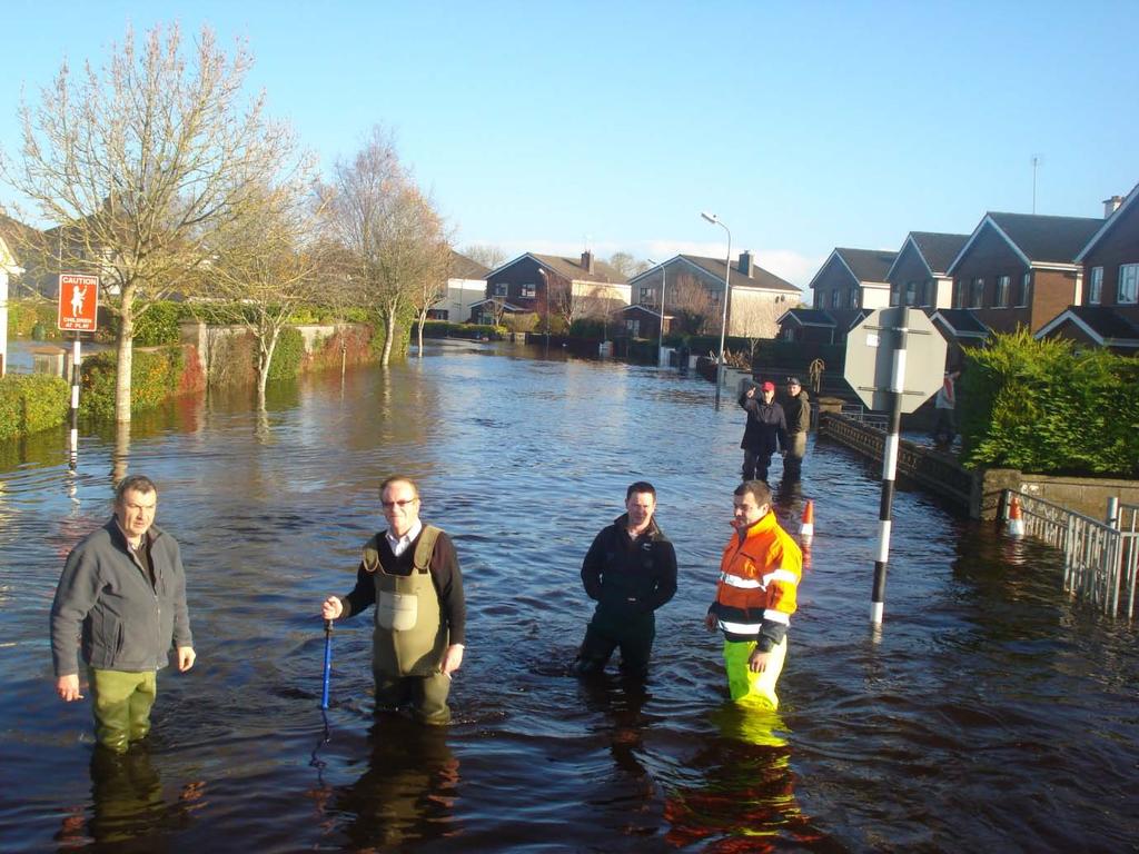
3 The level of the flood defences has been provided by referencing previous flood studies and flood levels recorded during the flooding of November 2009 which has been estimated at greater than a 1 in 800 year flood event. The max flood level recorded during the Nov 09 flood event was 39.33m OD. To allow for climate change and safety factor the flood defences include a freeboard of 300mm at hard installations (e.g. structural walls/piles) and a free board of 500mm at earth embankment. The wall detail has been constructed to a top level of m OD and the bund to a level of 39.85m OD. This gives protection during a 1 in 200 year flood event with adequate free board. The construction of the flood wall impacted on a substantial number of properties. The land owners have been very accommodating. Two of the primary land owners have dedicated the land free of charge to Galway County Council for the construction of the wall. They have also fully cooperated with the contractor in the construction of the wall and no payment what so every has been paid to any land owner. As outlined above, due to the flood sensitivity of this area if was crucial that this project be fast tracked to construction before a repeat flood event. If works were not carried out before the following winter Ballinasloe Town Council, Galway County Council and the OPW would have been in a difficult situation and open to severe criticism. During the construction of the wall a flood event occurred in February 2011, as shown in the photos below. Was it not for the flood wall in place a number of properties at the lowest end of Ashfield drive would have been flooded. This emphases the importance of this project going ahead. I am sure that this flood defence will provide savings into the future in preventing flooding. The residents in this area are also unable to get house insurance on their property but with the flood defence in place the insurance companies may be able to that that into account in their assessment. Uinsinn Finn C.Eng, B.Eng, MBA Senior Executive Engineer South Division, Galway County Council


4 Flooding Nov 09
5


6 DERRYMULLAN FLOOD DEFENCE WALL Area prior to construction Progress January 2011


7 Progress 8th March 2011 Photo of South East Wall, sheet piles in place and concrete capping under construction Photo of South West Wall, sheet piles in place with full faced concrete capping & cladding (gap shown will be narrowed and flood gates provided)


8 Photo of North East Bund, drain is culverted and headwall and bund under construction in foreground Flood gates in place


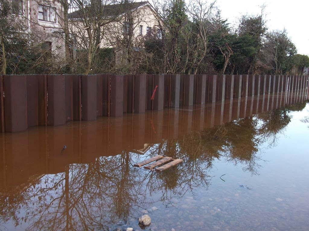
9 February Flooding during construction Penstock on culvert stream
10
11 Ordnance Survey Ireland Licence No. AR Ordnance Survey Ireland and Government of Ireland EXISTING DITCH TO BE CULVERTED WITH 900Ø PIPE SEE DRAWING C501 CULVERT No. 1 FOR LONGITUDINAL SECTION & RCD 005 FOR DETAILS. 1.1M HIGH BUND TOP OF BUND AOD MIN 900Ø HEADWALL TO NRA RCD\500\20, RCD\07 & RCD\13 IL mm Ø HEADWALL TO RCD 017, RCD\07 & 1.6M HIGH BUND RCD\13 TO CONTINUE AROUND BACK OF HEADWALL. TOP OF BUND 39.85M AOD MIN IL 37.9 IL = Ø HEADWALL TO RCD\500\20 RCD\13 IL LINE OF 400 DIAMETER RISING MAIN IL=1.2m EXISTING V-DITCH TO RE-ALIGNED AND BACK FILLED WHERE REQUIRED AND SCOUR PROTECTION PROVIDED AT BEND 6022 CH CH CH CL IL CH OVER PUMP CHAMBER TO NRA RCD/500/3 TYPE C900 CL 38.5 IL 37.9 AT CONNECTION TO 900 CULVERT CH CH EXISTING DITCH TO BE CULVERTED WITH 900mm PIPE. SEE DRAWING C501 CULVERT FOR LONGITUDINAL SECTION. INCLUDE PEA GRAVEL AND GEOTEXTILE SURROUND AS DRAINAGE LAYER AS DIRECTED BY EMPLOYERS REPRESENTATIVE CH CH MH CONNECTION TO EXISTING 1200 DIAMETER STORM DRAIN. CL IL EXISTING MANHOLE PROPOSED 900Ø CULVER TO TIE INTO CULVERT CROSSING UNDER ROAD. FINAL TERMINATION POINT OF FLOOD PROTECTION TO BE AGREED WITH ENGINEER SEE DRAWING IN 100 CL IL CH CH IN 300 CL IL EXISTING DITCH TO BE CULVERTED WITH 600Ø CONCRETE PIPE HEADWALL TO NRA RCD\500\20 & RCD\07 HEADWALL TO NRA RCD\500\20 & RCD\07 CH DISCHARGE INTO EXISTING DRAIN IL = EXISTING DITCH TO BE CLEARED EXISTING DRAIN IL = CH BUND TO BE 1:10 AND GATE REPLACED WITH SIMILAR RCD/300/9 TYPE 2 EXISTING SAPLINGS TO BE REMOVED CH PROPOSED POST & WIRE FENCE TO NRA/RCD/300/1 TYPE2 CH 1 IN 300 TO NRA RCD 500/1 EXISTING 12' FIELD GATE TO BE REPLACED WITH GALVANISED FIELD GATE TO NRA/RCD/300/9 TYPE2 1:10 SLOPE BUND FOR ACCESS BUND TO CONTINUE AROUND BACK OF HEADWALL RODDING EYE TO BE INSTALLED AT HIGH POINT OF CH 525 CL IL M HIGH BUND ACROSS FIELD AND ALONG HEDGE LINE TOP OF BUND 1 IN 100 TO NRA RCD 500/1 CL IL CL IL CH CL IL CH CH CH CH CH M HIGH BUND TOP OF BUND 39.85M AOD MIN CL IL M HIGH BUND WALL TOP OF BUND 39.85M AOD MIN EXISTING GATE AND FENCE TO BE RETAINED BUND MATERIAL TO OVERLAP WITH SHEET PILE WALL FOR 1.5M 1.7M HIGH BUND INSIDE FIELD BOUNDARY. TOP OF BUND 39.85M AOD MIN. RETAIN EXISTING TREES AND FENCE 2No. 550 x 550 x 1200mm MASS CONCRETE HEADWALLS TO 150mm AGE OUTLET DO NOT SCALE A1 INSTALL 900mm Ø CULVERT AND HEAD WALL TO NRA/RCD\500\20, RCD\07 & RCD\13.TOP OF HEADWALL 39.65M AOD IL M HIGH BUND TO RETURN AT FRONT OF WALL FOR 1.5M 1.4M HIGH SHEET PILE WALL TOP OF WALL AOD MIN RODDING EYE AT CH 182 CL IL M HIGH SHEET PILE WALL TOP OF WALL 39.65M AOD MIN 1.2M HIGH SHEET PILE WALL TOP OF WALL 39.65M AOD MIN INSTALL 225mm Ø HEAD WALL IN WALL HEADWALL TO NRA RCD\500\20, RCD\07 & RCD\13 PROPOSED V-DITCH TO RCD001 CH CH m OVER PUMP CHAMBER ON BACK OF HEADWALL NRA RCD/500/3 TYPE C1500 IL CH ACCESS CHAMBER NRA RCD/500/3 TYPE C900 CL IL M HIGH SHEET PILE WALL EXISTING DITCH REGRADED WHERE NECCESARY 1.8M HIGH SHEET PILE WALL OPC4 CH CL IL M HIGH SHEET PILE WALL INSIDE DITCH TOP OF WALL 39.85M AOD MIN CH m CH EXISTING LAND DRAINAGE PIPES TO BE SURVEYED AND REPLACED IF NECCESSARY BY 900mm Ø CULVERT FROM PROPOSED HEAD WALL TO EXISTING CULVERT ROAD CROSSING. RODDING EYE AT CH 176 CL IL DITCH TO BE BACKFILLED IN ACCORDANCE WITH RCD/004 NEW 150Ø TO BE PROVIDED AT 1: M HIGH SHEET PILE WALL INSIDE DITCH TOP OF WALL 39.85M AOD MIN CH DITCH TO BE BACKFILLED IN ACCORDANCE WITH RCD/004 NEW TO BE PROVIDED DITCH TO BE BACKFILLED IN ACCORDANCE WITH RCD/004 NEW 150Ø TO BE PROVIDED CH GROUND TO BE EXCAVATED TO 1.2m BELOW GROUND LEVEL & BACKFILLED WITH COHESIVE GENERAL FILL UNDER BUND. CL IL CL IL CH CH CH CH CH CH CH CH CH CH BUND TO TIE INTO RETURN OF SHEET PILE WALL AND OVERLAP WITH WALL FOR 1.5M 1.8M HIGH SHEET PILE WALL 1.8M HIGH SHEET PILE WALL. 1.8M HIGH SHEET PILE WALL REMOVE EXISTING FENCE ACROSS OPEN CHANNEL AND REPLACE WITH 3.3M HIGH HEAD WALL TO CULVERT MIN HEIGHT 39.85M AOD MIN. SEE DETAIL 1. IL M HIGH BUND INSIDE FIELD BOUNDARY TOP OF BUND 39.85M AOD MIN. RETAIN EXISTING TREES AND FENCE 1.0M HIGH BUND INSIDE FIELD BOUNDARY TOP OF BUND 39.85M AOD MIN. 1 IN 300 TO NRA RCD\500\1 TYPE I ACCESS CHAMBER TO NRA RCD/500/3 TYPE C900 CL IL LINE OF TEMPORARY FENCING TO BE PROVIDED IN S.P.A. IN ACCORDANCE WITH ENVIRONMENTAL REQUIREMENTS. FENCING TO NRA/RCD/300/4 1 DETAIL Scale: 1: M HIGH SHEET PILE WALL RODDING EYE TO BE INSTALLED AT HIGH POINT OF S CH 370 CL IL m CH CH CH CH CH M HIGH SHEET PILE WALL 2.0M HIGH SHEET PILE WALL MH01 1.4M HIGH SHEET PILE 1 IN 300 TO NRA RCD 1 IN 300 TO NRA RCD 500/1 2.0M HIGH SHEET PILE WALL OPC1 EXISTING DITCH REGRADED WHERE NECCESARY 1.4M HIGH SHEET PILE WALL 2.0m OUTSIDE TEMPORARY HEN HOUSES. 1.4M HIGH SHEET PILE WALL EXISTING SHEDS CH CH EXISTING ACCESS CH CH CL 37.9 IL 36.4 EXISTING DITCH TO BE PARTIALLY BACK FILLED TO RCD/004 PROPOSED V-DITCH TO RCD001 PROPOSED V-DITCH CONNECTION TO EXISTING V-DITCH 1.2M HIGH SHEET PILE WALL CH 470 CL IL PROPOSED 4.0M WIDE x 1.5M HIGH 'FLOOD CONTROL' OR SIMILAR HINGED FLOOD GATE. SEE SPECIFICATION FOR DETAILS REMOVABLE CORNER SOCKET POST, HINGES, SEALS ETC. TO MANUFACTURES DETAILS. GATES TO BE LOCKABLE IN OPEN AND CLOSED POSITIONS CH CH 1 IN 300 TO NRA RCD 500/1 EXISTING TIMBER POST & RAIL FENCE TO BE REMOVED AND REPLACED ON COMPLETION OF FLOOD WALL CH CH ESB MINI PILLAR TO BE TEMPORALLY RELOCATED DURING CONSTRUCTION IF REQUIRED. ALL TO BE AGREED WITH THE ESB CH CH M HIGH SHEET PILE WALL TOP OF WALL 39.65M AOD MIN TO BE KEPT 3m FROM HEDGE ROW BUND TO TIE INTO RETURN OF SHEET PILE WALL AND OVERLAP WITH WALL FOR 1.5M TOP OF BUND 39.85m TELECOMS CABINET TO BE TEMPORALLY RELOCATED DURING CONSTRUCTION OF WALL IF REQUIRED. ALL TO BE AGREED WITH THE ESB OVER PUMP CHAMBER TO NRA RCD/500/3 TYPE C900 CL IL CH m HIGH CLAY BUND PILE WALL TO TIE IN WITH EXISTING STONE BRIDGE WALLS BUND TO TIE INTO RETURN OF SHEET PILE WALL AND OVERLAP WITH WALL FOR 1.5M TO DISCHARGE INTO STREAM, TO BE CONCRETE ENCASED. CL IL m HIGH BUND WALL TO TIE INTO EXISTING RAILWAY ABUTMENT WALL. TOP OF BUND 39.85M AOD MIN. NOTES :- These notes apply except where noted otherwise on the drawings or in the Specification GENERAL NOTES :- 1. DO NOT SCALE. Use only figured dimensions. Atkins House Airside Business Park, Swords, Co. Dublin Tel (+353) Fax (+353) Unit 2B 2200 Cork Airport Business Park Cork Tel (+353) Fax (+353) nd Floor Technology House Parkmore Technology Park Galway Tel (+353) Fax (+353) Drawing Title PROPOSED FLOOD PROTECTION WALL - WALL PLAN 2. All dimensions are in millimetres unless stated otherwise. 3. Levels shown to Malin Head Datum unless stated otherwise. 4. Coordinates are to National Grid unless stated otherwise Millimetres 100 Rev Description By Date Chk'd Auth Project BALLINASLOE FLOOD PROTECTION Original Scale 1:1000 Job No Drawn WMcG Date MAY 2010 Unique Drg No. C101 Checked Authorised Status BH BMcK Revision
12
(b) Discuss in brief shaft spillway with neat sketches. Marks 04. OR Q (2) Explain in brief USBR stilling basin. Marks 08
 Discuss in brief shaft spillway with neat sketches. Marks 04. OR Q (2) Explain in brief USBR stilling basin. Marks 08") (b) Discuss in brief shaft spillway with neat sketches. Marks 04 OR Q (2) Explain in brief USBR stilling basin. Marks 08 Stilling Basins The basins are usually provided with special appurtenances including
(b) Discuss in brief shaft spillway with neat sketches. Marks 04 OR Q (2) Explain in brief USBR stilling basin. Marks 08 Stilling Basins The basins are usually provided with special appurtenances including
Created by Simpo PDF Creator Pro (unregistered version) Asst.Prof.Dr. Jaafar S. Maatooq
 Asst.Prof.Dr. Jaafar S. Maatooq") Lect.No.9 2 nd Semester Barrages, Regulators, Dams 1 of 15 In order to harness the water potential of a river optimally, it is necessary to construct two types of hydraulic structures, as shown in Figure
Lect.No.9 2 nd Semester Barrages, Regulators, Dams 1 of 15 In order to harness the water potential of a river optimally, it is necessary to construct two types of hydraulic structures, as shown in Figure
Sewer Audit - Design Checklist Gravity sewers, sewage pumping stations and pressure sewers
 Question Relevant Clauses Design checked? Do the drawings show an appropriate revision history, and is 1.1 the design complete, checked and effectively ready for construction? 1.2 Has the whole catchment
Temporary Watercourse Crossing: Culverts
 Temporary Watercourse Crossing: Culverts DRAINAGE CONTROL TECHNIQUE Low Gradient Velocity Control Short Term Steep Gradient Channel Lining Medium-Long Term Outlet Control Soil Treatment Permanent Symbol
Contact the Jurisdictional Engineer for materials allowed by each jurisdiction.
 Design Manual Chapter 3 - Sanitary Sewers 3C - Facility Design 3C-1 Facility Design A. Capacity of Pipe Pipe sizes 15 inches and smaller should carry the peak flow at a depth of no more than 0.67 of the
Flood Hazard Assessment Report Falls Gulch, Larimer County, Colorado January 16, 2013
 United States Department of Agriculture Natural Resources Conservation Service Denver Federal Center Building 56, Room 2604 P.O. Box 25426 Denver, CO 80225 720-544-2818-OFFICE alton.albin@co.usda.gov Flood
NRA TB 13 Revised Road Drainage Standards
 NRA TB 13 Revised Road Drainage Standards GE-TBU-01026 March 2015 General Technical TRANSPORT INFRASTRUCTURE IRELAND (TII) PUBLICATIONS About TII Transport Infrastructure Ireland (TII) is responsible for
Special Provision No. 405F03 March 2005
 PIPE SUBDRAINS - Item No. VIDEO CAMERA INSPECTION Item No. Special Provision No. 405F03 March 2005 OPSS 405, February 1990, Construction Specification for Pipe Subdrains is deleted in its entirety and
Description Unit Quantity Rate Kshs. Amount Kshs.
 BILL No.1 40m3 MASONRY STORAGE TANK No. Description Unit Quantity Rate Kshs. Amount Kshs. 1 SETTING OUT AND EARTH WORKS 1.1 General site clearance and setting out 1.2 Excavate over site 200mm to remove
Unique ID: (from PFRA database) Location: Clonfert, Co. Galway. Stage 1: Desktop Review
 Location: Clonfert, Co. Galway. Stage 1: Desktop Review") Location: Clonfert, Co. Galway Unique ID: 252906 (from PFRA database) Initial OPW Designation APSR AFRR IRR Co-ordinates Easting: 197134 Northing: 221731 River / Catchment / Sub-catchment Un-named minor
Location: Clonfert, Co. Galway Unique ID: 252906 (from PFRA database) Initial OPW Designation APSR AFRR IRR Co-ordinates Easting: 197134 Northing: 221731 River / Catchment / Sub-catchment Un-named minor
Storm Drain Inlet Protection
 Categories EC Erosion Control SE Sediment Control TC Tracking Control WE Wind Erosion Control Non-Stormwater NS Management Control Waste Management and WM Materials Pollution Control Legend: Primary Category
Redi Rock Specification and Installation Manual
 Redi Rock Specification and Installation Manual 1.0 General Scope This Specification covers the Design, Materials and Installation of Redi Rock modular block Retaining and Freestanding Wall systems as
GUIDELINES FOR INSTALLATION OF ON-SITE SEWAGE SYSTEMS
 UTAH COUNTY HEALTH DEPARTMENT Div. of Environmental Health 151 South University Avenue, Provo 84601 (801) 851-7525 FAX 851-7521 GUIDELINES FOR INSTALLATION OF ON-SITE SEWAGE SYSTEMS This is intended to
SPECIFICATION FOR PIPE CULVERT CONSTRUCTION
 SPECIFICATION FOR PIPE CULVERT CONSTRUCTION 1. SCOPE Pipe culverts shall be constructed in accordance with this specification and in conformity with the lines, levels and cross-sections shown on the drawings.
Anchorplex retaining wall construction guide. Building. Anchorplex. Retaining Wall Systems
 Anchorplex retaining wall construction guide Building Anchorplex Retaining Wall Systems Table of Contents and ow to Use This Guide table of contents ow to Use This Guide. 2 About the Anchorplex System.
CONSTRUCTION SURVEY. Construction survey includes personnel, equipment, and supplies required for, but not limited to, the following:
 CONSTRUCTION SURVEY PART 1 - GENERAL 1.01 SECTION INCLUDES Construction survey includes personnel, equipment, and supplies required for, but not limited to, the following: A. Construction Survey: 1. Project
DESIGN AND CONSTRUCTION OF DERRY ROAD AND CANADIAN NATIONAL RAIL GRADE SEPARATION
 DESIGN AND CONSTRUCTION OF DERRY ROAD AND CANADIAN NATIONAL RAIL GRADE SEPARATION Vireak Hinh, P.Eng. R.V. Anderson Associates Ltd., Toronto, Canada Jennifer Trimble Region of Halton, Oakville, Canada
SECTION 6 STORMWATER AND LAND DRAINAGE
 SECTION 6 STORMWATER AND LAND DRAINAGE Final Version, Approved September 2003 Section 6 and Land Drainage Contents 6.1 PERFORMANCE STANDARDS... 2 6.1.1 General... 2 6.2 MEANS OF COMPLIANCE... 3 6.2.1 General...
UTILITY NOTES GENERAL CONSTRUCTION NOTES PAVING AND GRADING NOTES: TREE PROTECTION NOTES
 GENERAL CONSTRUCTION NOTES PAVING AND GRADING NOTES: UTILITY NOTES PROPOSED LEGEND 66.50 66.50 GROUND SPOT ELEVATION GROUND SPOT ELEVATION (MATCH EXISTING GRADE) MATCH EXISTING GRADE MITERED END SECTION
Attachment 12 Stage 1 Flood Risk Assessment (IE RP-0001)
") IE0311133-22-RP-0001, Issue A 17/10/2013 Attachment 12 Stage 1 Flood Risk Assessment (IE0311133-30-RP-0001) IE0311133-22-RP-0001_A_02.DOC Flood Risk Assessment Celebrating 40 Years in Business Jazz Pharmaceuticals
IE0311133-22-RP-0001, Issue A 17/10/2013 Attachment 12 Stage 1 Flood Risk Assessment (IE0311133-30-RP-0001) IE0311133-22-RP-0001_A_02.DOC Flood Risk Assessment Celebrating 40 Years in Business Jazz Pharmaceuticals
DRAINAGE & DESIGN OF DRAINAGE SYSTEM
 Drainage on Highways DRAINAGE & DESIGN OF DRAINAGE SYSTEM P. R.D. Fernando Chartered Engineer B.Sc.(Hons), M.Eng. C.Eng., MIE(SL) Drainage Requirement of Highway Drainage System Introduction Drainage means
Alberta Bridge Inventory STANDARD BRIDGE & CULVERT COMPONENTS. Standard Bridges. Typical Bridge Components. In Alberta there are about 13,300 bridges.
 STANDARD BRIDGE & CULVERT COMPONENTS Alberta Bridge Inventory In Alberta there are about 13,300 bridges. Types of bridges in Alberta: Standard bridges 3521 (26%) Bridge size culverts 8348 (63%) Major bridges
B. Subsurface data is available from the Owner. Contractor is urged to carefully analyze the site conditions.
 SECTION 31 23 33 - TRENCHING, BACKFILLING AND COMPACTION PART 1 - GENERAL 1.1 SCOPE A. This Section specifies the requirements for excavating and backfilling for storm sewer, sanitary sewer, water distribution
AUGUST 2017 HASTINGS. retaining walls installation guide
 AUGUST 2017 HASTINGS retaining walls installation guide RETAINING WALL INSTALLATION GUIDE RETAINING WALL information Austral Masonry retaining wall blocks are an ideal choice for retaining walls in gardens,
Welded Mesh Gabions and Mattresses River Protection Design Guide Anping County Zhuoda Hardware Mesh Co.,Ltd. Wire Mesh Industrial Zone, Anping
 Welded Mesh Gabions and Mattresses River Protection Design Guide Anping County Zhuoda Hardware Mesh Co.,Ltd. Wire Mesh Industrial Zone, Anping County, Hebei, P. R. China. Tel : 0086-318-7752001 7531068
SEGMENTAL BLOCK RETAINING WALLS. Comply with Division 1 - General Provisions and Covenants, as well as the following:
 SEGMENTAL BLOCK RETAINING WALLS PART 1 - GENERAL 1.01 SECTION INCLUDES Segmental Block Retaining Walls 1.02 DESCRIPTION OF WORK Constructing segmental block retaining walls. 1.03 SUBMITTALS Comply with
Index. Composition and Order of Plan Set. Utility Plan... 5
 City of Des Plaines Public Works and Engineering Department Revised-October 5, 2012 Index Composition and Order of Plan Set Title Page Number Cover Sheet... 1 Requirements for Site Development... 2 Grading
K_`j `e]fidxk`fe `j Yifl^_k kf pfl Yp Fncj?Xcc <em`ifed\ekxc nfib`e^ `e gxike\ij_`g n`k_ BcXi^\jk\i gif[lzkj% '/+, *., (/'(
![K_`j `e]fidxk`fe `j Yifl^_k kf pfl Yp Fncj?Xcc <em`ifed\ekxc nfib`e^ `e gxike\ij_`g n`k_ BcXi^\jk\i gif[lzkj% '/+, *., (/'(](/thumbs/72/66326248.jpg "K_`j `e]fidxk`fe `j Yifl^_k kf pfl Yp Fncj?Xcc <em`ifed\ekxc nfib`e^ `e gxike\ij_`g n`k_ BcXi^\jk\i gif[lzkj% '/+, *., (/'(") Excellent Treatment PD0064, Issue 1 INSTALLATION INSTRUCTIONS FOR N3 to N5 NITRIFICATION BIODISCS Introduction PD0064, Issue 1 Klargester BioDiscs are manufactured in Glass Fibre Reinforced Polyester (GRP).
Excellent Treatment PD0064, Issue 1 INSTALLATION INSTRUCTIONS FOR N3 to N5 NITRIFICATION BIODISCS Introduction PD0064, Issue 1 Klargester BioDiscs are manufactured in Glass Fibre Reinforced Polyester (GRP).
MECHANICALLY STABILIZED EARTH (MSE) WALL SYSTEMS
 WALL SYSTEMS") DRAINAGE SOLUTIONS SINCE 1908 MECHANICALLY STABILIZED EARTH (MSE) WALL SYSTEMS PERMANENT AND TEMPORARY ENGINEERED WALL SOLUTIONS ECONOMICAL DURABLE VERSATILE ARMTEC.COM MSE RETAINING WALLS Armtec Mechanically
DRAINAGE SOLUTIONS SINCE 1908 MECHANICALLY STABILIZED EARTH (MSE) WALL SYSTEMS PERMANENT AND TEMPORARY ENGINEERED WALL SOLUTIONS ECONOMICAL DURABLE VERSATILE ARMTEC.COM MSE RETAINING WALLS Armtec Mechanically
Water Control Structures Selected Design Guidelines Alberta Environment Page 17-1
 Alberta Transportation Water Control Structures Selected Design Guidelines Alberta Environment Page 17-1 17.0 MAIN CANAL CONVEYANCE STRUCTURES 17.1 General Conveyance structures typically employed on main
Highway Drainage 1- Storm Frequency and Runoff 1.1- Runoff Determination
 Highway Drainage Proper drainage is a very important consideration in design of a highway. Inadequate drainage facilities can lead to premature deterioration of the highway and the development of adverse
Lyon Creek Cedar Way Stormwater Detention Dam Operation and Maintenance Manual
 Lyon Creek Cedar Way Stormwater Detention Dam Operation and Maintenance Manual Prepared by: Mike Shaw Stormwater Program Manager City of Mountlake Terrace January 2010 Section I General Information This
SECTION EXCAVATION AND EMBANKMENT. B. Subbase Grading A samples for gradation analysis.
 PART 1 GENERAL 1.1 DESCRIPTION A. The WORK under this Section includes providing all labor, materials, tools and equipment necessary for excavation and embankment construction to the lines, grades and
1. All underground utilities under railroad tracks shall be encased in a larger pipe or conduit called the casing pipe.
 MTS Jack and Bore Design Criteria Note: For the purposes of this Design Criteria and subsequent Construction Notes, the term Jack and Bore is used generically to refer to a number of trenchless construction
10.1 INTRODUCTION 10.1 DRAINAGE
 CHAPTER 10 DRAINAGE 10.1 INTRODUCTION The drainage system manages both surface and subsurface water coming off the road surface and from the surrounding countryside. The purpose of the system is to ensure
4701 Piccadilly Place South - Creek Realignment Hydrology and Hydraulic Design 2016 Update for Revision 2 Drawing
 30 Gostick Place North Vancouver, BC V7M 3G3 604.980.6011 www.nhcweb.com NHC Ref. No. 30000457 2016 September 16 Dr. Sukhi Muker 1785 Bellevue Avenue West Vancouver, BC V7V 1A8 Via email: sukhi@drsukhi.com
SECTION TRENCHING & BACKFILLING
 SECTION 02225 - TRENCHING & BACKFILLING 1.0 GENERAL 1.1 Work included in this Section includes trenching and backfilling for underground pipelines and related structures only. 1.2 Reference Specifications
GRADING & DRAINAGE PERMIT SOIL EROSION AND SEDIMENTATION CONTROL PERMIT PROGRAM OVERVIEW
 GRADING & DRAINAGE PERMIT SOIL EROSION AND SEDIMENTATION CONTROL PERMIT PROGRAM OVERVIEW Chapter 8 Building and Building Regulations, Article XIII Grading and Drainage and Article XV Soil Erosion and Sedimentation
SECTION 3 DRAINAGE. 3-1 General. 3-2 Drainage Ordinances and Legal Requirements
 SECTION 3 DRAINAGE 3-1 General All Drainage plans for proposed development shall be prepared by a Professional Engineer registered in Virginia, except as noted below. Further, their seal and signature
INDEX FOR SPECIFICATIONS FOR REMOVING CULVERTS AND PLACING CULVERTS SCOPE... 1
 March 2002 No. 400 INDEX FOR SPECIFICATIONS FOR REMOVING CULVERTS AND PLACING CULVERTS 400. 1 SCOPE... 1 400. 2 REMOVING CULVERTS AND TIMBER STRUCTURES 2.1 Concrete and Metal Pipe Culverts... 1 2.2 Structural
Ponds. Pond A water impoundment made by excavating a pit, or constructing a dam or an embankment.
 POND SITE SELECTION AND CONSTRUCTION Uses, Planning, & Design David Krietemeyer Area Engineer USDA-NRCS June 20, 2008 Uses Considerations for Location of Commonly Used Terms Pond A water impoundment made
SECTION 820 PUMP STATION DEMOLITION AND SITE RESTORATION
 820-1 SCOPE OF WORK: SECTION 820 PUMP STATION DEMOLITION AND SITE RESTORATION a. Furnish all labor, materials, equipment, and incidentals required for demolition and/or removal and disposal of existing
LANDSCAPE RETAINING WALLS
 SUDAS Standard Specifications Division 9 - Site Work and Landscaping Section 9070 - Landscape Retaining Walls LANDSCAPE RETAINING WALLS PART - GENERAL.0 SECTION INCLUDES A. Modular Block Retaining Walls
Houston Community College 3200 Main Parking Garage November 15, 2010 Houston Community College
 SECTION 323113 - CHAIN LINK FENCES AND GATES PART 1 - GENERAL 1.1 RELATED DOCUMENTS A. Drawings and general provisions of the Contract, including General and Supplementary Conditions and Division 01 Specification
MOA Project # Golden View Drive Intersection & Safety Upgrades
 Appropriate transitions can include extending the insulation beyond the roadway improvements, reducing the insulation thickness, or angling the insulation downward. Use of a frost tolerant section, an
SECTION FACILITY SANITARY SEWERS
 SECTION 22 13 13 FACILITY SANITARY SEWERS PART 1 - GENERAL 1.1 RELATED DOCUMENTS A. Drawings and general provisions of the Contract, including General and Supplementary Conditions and Division 01 Specification
Electrical Work. NOV Embankments Over Swamps and Compressible Soils
 GENERAL & CONSTRUCTION S OPS GENERAL CONDITIONS OF CONTRACT NOV 2006 100 OPS General Conditions of Contract DIVISION 1 - GENERAL S 106 Electrical Work 120 180 The Use of Explosives General Specification
CHECK THE LOWER RIGHT CORNER OF EACH DETAIL FOR THE LATEST REVISION.
 Standard Drawings Index NOTE: The specifications for materials and workmanship shall conform to the latest edition or the "Standard Specifications for Public Works Construction" published by the North
CHECKLIST FOR STREETS, INLETS, AND STORM SEWER DESIGN
 CHECKLIST FOR STREETS, INLETS, I. STREET CLASSIFICATION AND DESIGN CRITERIA A. Determine drainage classification for the roadway section using Table 7-1 or Table 7-2. B. Determine the allowable flow depth
SECTION A1 EXCAVATION AND BACKFILL GENERAL
 SECTION A1 EXCAVATION AND BACKFILL GENERAL The work under this section shall include all excavation to such width and depth as shown on the drawings, specified herein, or ordered by the Engineer. Such
Appendix 4. Bills of Quantities
 Appendix 4. Bills of Quantities 201 A4.1 Deep trench latrines Partitions of local materials 1m apart Timber foot rests and floor plates Lightweight timber frame Excavated soil (used for back-fill) Plastic
ARCHITECTURAL DRAWINGS
 PROJECT DETAILS Implementation Partner: Project title: Grant No.: KIS062 Content : ARCHITECTURAL DRAWINGS SHEET NO. REHABILITATION OF GRANT NO.: - KIS062 COVER SHEET INDEX SHEET CONTENTS 01 02 03 04 05
Stormwater Local Design Manual For Houston County, Georgia
 Stormwater Local Design Manual For Houston County, Georgia Adopted November 15, 2005 TABLE OF CONTENTS 1. FORWARD... 1 2. GENERAL LEVEL OF SERVICE STANDARDS... 2 2.1. DETENTION REQUIREMENTS... 2 2.1.1.
Irrigation Rehabilitation Program Design and Construction Standards
 Irrigation Rehabilitation Program Design and Construction Standards Prepared by the IRP Standards Review Committee For Alberta Agriculture and Rural Development, Irrigation Secretariat April 26, 2010 Adopted
SPECIFICATIONS FOR PRECAST MODULAR BLOCK RETAINING WALL SYSTEM (revised 5/8/7)
") Page 1 of 7 STONE STRONG SYSTEMS SPECIFICATIONS FOR PRECAST MODULAR BLOCK RETAINING WALL SYSTEM (revised 5/8/7) PART 1: GENERAL 1.01 Description A. Work includes furnishing and installing precast modular
Page 1 of 7 STONE STRONG SYSTEMS SPECIFICATIONS FOR PRECAST MODULAR BLOCK RETAINING WALL SYSTEM (revised 5/8/7) PART 1: GENERAL 1.01 Description A. Work includes furnishing and installing precast modular
Sanitary Sewer Extensions, Lift Stations, and Force Mains Engineering Report Form. I. General Information. 1. Name of Facility:
 Oklahoma Department of Environmental Quality Water Quality Division Phone: 405-702-8100 Construction Permitting Section 707 N. Robinson, OKC, OK 73102-6010 P.O. Box 1677, OKC, OK 73101-1677 Sanitary Sewer
SPECIAL CONDITIONS FOR PIPE JACKING (PJ) October, 2006
 October, 2006") Michigan Department Of Transportation 3703C (11/06) 1 Materials 1.1 Pipe SPECIAL CONDITIONS FOR PIPE JACKING (PJ) October, 2006 Page 1 of 5 The type of pipe used for the pipe jacking method shall be capable
Michigan Department Of Transportation 3703C (11/06) 1 Materials 1.1 Pipe SPECIAL CONDITIONS FOR PIPE JACKING (PJ) October, 2006 Page 1 of 5 The type of pipe used for the pipe jacking method shall be capable
Modular Sediment Barriers (Instream)
") Modular Sediment Barriers (Instream) INSTREAM PRACTICES Flow Control No Channel Flow Dry Channels Erosion Control Low Channel Flows Shallow Water Sediment Control High Channel Flows Deep Water Symbol Photo
Modular Sediment Barriers (Instream) INSTREAM PRACTICES Flow Control No Channel Flow Dry Channels Erosion Control Low Channel Flows Shallow Water Sediment Control High Channel Flows Deep Water Symbol Photo
STREAM STABILIZATION PLAN
 DISTRICT COUNTY ROUTE SECTION SHEET 6- PHILADELPHIA 47 14B 1 OF 2 NOTES: REVISION NUMBER REVISIONS DATE BY 1. REFER TO EROSION AND SEDIMENT POLLUTION CONTROL PLANS FOR LOCATION OF TEMPORARY CONSTRUCTION
Iarnród Éireann/Irish Rail Risk Management and Scour Protection Works on Masonry Arches and Piers
 Iarnród Éireann/Irish Rail Risk Management and Scour Protection Works on Masonry Arches and Piers Assessment & Maintenance of Masonry Arch Bridges Engineers Ireland 29 th January 2016 Stephen Bateson BSc
DESIGN STANDARDS. Division 02 Existing Conditions- Site Work. General
 DESIGN STANDARDS Division 02 Existing Conditions- Site Work General I. This Division includes: A. Demolition B. Clearing and Grubbing C. Excavation, Backfill and Compaction D. Pavement Base E. Paving and
DIVISION 31 EARTHWORK 2006 Edition, Published January 1, 2006; Division Revision Date: January 31, 2012
 2006 Edition, Published January 1, 2006; Division Revision Date: January 31, 2012 PART FIVE DOCUMENTS FOR SITE AND INFRASTRUCTURE 31 00 00. EARTHWORK 31 10 00. SITE CLEARING.1 STRUCTURE REMOVAL: Include
DAM INSPECTION CHECKLIST Department of Environmental Protection Bureau of Waterways Engineering Division of Dam Safety
 DAM INSPECTION CHECKLIST Department of Environmental Protection Bureau of Waterways Engineering Division of Dam Safety NAME OF DAM: Milltown Dam DEPDAMNO.: 15-146 LOCATION: Municipality: East Goshen Township
THE ABATEMENT PLAN. beneficial abatement plan. For the purpose of defining the pollution potential of surface waters
 THE ABATEMENT PLAN GENERAL PLAN Preventing surface waters from entering deep mine workings apparently offers the most beneficial abatement plan. For the purpose of defining the pollution potential of surface
Grade separated interchange at the intersection of U.S. Hwy 17 Bypass and Farrow Parkway
 Grade separated interchange at the intersection of U.S. Hwy 17 Bypass and Farrow Parkway Jeff Sizemore, P.E. Geotechnical Design Support Engineer SCDOT Ed Tavera, P.E. Principal Geotechnical Engineer Geoengineers
B421-2 PIPE CULVERTS OPSS 421
 B421-2 OPSS 421 421.1 GENERAL Pipe culverts are installations designed to provide for the conveyance of surface water, pedestrians or livestock using preformed or pre-cast pipe sections, circular or non-circular
REROUTING DRAINAGE SYSTEMS
 MINNESOTA WETLAND RESTORATION GUIDE REROUTING DRAINAGE SYSTEMS TECHNICAL GUIDANCE DOCUMENT Document No.: WRG 4A-4 Publication Date: 10/14/2015 Table of Contents Introduction Application Design Considerations
Med (3) Locator Information/GPS GPS shows 16 ft accuracy Lat: Impact Rating
 Locator Information/GPS GPS shows 16 ft accuracy Lat: Impact Rating") (FERC 1927) Erosion Control Plan Site Remediation/ Assessment Form Site # Med (3) LM2-25 Priority Ranking Locator Information/GPS GPS shows 16 ft accuracy Lat: Long: Impact Rating 5 Start Project Development:
(FERC 1927) Erosion Control Plan Site Remediation/ Assessment Form Site # Med (3) LM2-25 Priority Ranking Locator Information/GPS GPS shows 16 ft accuracy Lat: Long: Impact Rating 5 Start Project Development:
SECTION 1100 GRADING 1102 MATERIALS AND DEFINITIONS.
 SECTION 1100 GRADING 1101 SCOPE. This section covers the performance of all work required for grading the project in coordination with all previous work performed at the locations shown on the contract
SPECIFICATIONS FOR STREET CONSTRUCTION WITHIN THE TOWN OF PLAINVILLE
 SPECIFICATIONS FOR STREET CONSTRUCTION WITHIN THE TOWN OF PLAINVILLE BE IT ORDAINED by the Town Council of the Town of Plainville: SECTION 1. SUBDIVISIONS. All subdivisions hereinafter developed within
Irrigation System. BWCDD Zanjero Training 2/13/2008
 Irrigation System BWCDD Zanjero Training Session #7 2/13/2008 Irrigation System The (main) intake structure t directs water from the source of supply, such as a reservoir or a river, into the irrigation
Report on Archaeological Testing of Luas Line A1 Belgard to Saggart, Co.Dublin.
 Project code: RPLT08 Client: Railway Procurement Agency Date: October, 2008. Report on Archaeological Testing of Luas Line A1 Belgard to Saggart, Co.Dublin. Director: Liam Hackett. Author : Liam Hackett.
CONSTRUCTION PLAN REVIEW CHECKLIST FOR PRIVATE DEVELOPMENT
 ADDITION NAME: City of Grapevine, Texas CONSTRUCTION PLAN REVIEW CHECKLIST FOR PRIVATE DEVELOPMENT Updated April 16, 2018 Public Works Department Engineering Division 200 South Main Street Grapevine, Texas
Coleraine to Derry~Londonderry ROUTE UPGRADE WORKS
 Coleraine to Derry~Londonderry ROUTE UPGRADE WORKS Alan Cudlipp CEng FICE FPWI Technical Director - Professional Head of Track Engineering, Mott MacDonald Contents Introduction and project summary Background
Attachment D-1: Civil/Structural Scope of Work
 Attachment D-1: Civil/Structural Scope of Work Project: Location: Targa Sound Renewable Fuels Project Tacoma, WA Prepared by: NORWEST ENGINEERING Consulting Engineers 4110 N.E. 122 nd Avenue, Portland,
MODEL Stormwater Local Design Manual. City of Centerville
 MODEL Stormwater Local Design Manual City of Centerville Adopted December 6, 2005 TABLE OF CONTENTS 1. FORWARD... 1 2. GENERAL LEVEL OF SERVICE STANDARDS... 1 2.1. DETENTION REQUIREMENTS... 1 2.1.1. Discharge
2014 WORKSHOP Field Trip 3
 2014 WORKSHOP Field Trip 3 This trip visits a RoaDrain geosynthetic drainage material demo, GRS-IBS bridge project, and a completed project from 2011. Site 1 - Laurel Run Road: Recently completed project
SECTION 11: REGULATORY FLOODWAYS
 SECTION 11: REGULATORY FLOODWAYS Contents 11.1. The Floodway... 11-2 11.1.1. The floodway concept... 11-2 11.1.2. Floodway map... 11-2 11.1.3. Floodway permitting... 11-3 11.1.4. Changing the floodway...
PART 3 - STANDARDS FOR SEWERAGE FACILITIES DESIGN OF STORM SEWERS
 PART 3 - STANDARDS FOR SEWERAGE FACILITIES 3.3 - DESIGN OF STORM SEWERS 3.301 Design of Storm Sewers A. General Information B. Investigations and Surveys C. Special Projects 3.302 Design Criteria for Storm
Mr. Michael Malone CPS Energy 145 Navarro Street San Antonio, Texas Project No
 Environmental Resources Management January 13, 2017 Mr. Michael Malone 145 Navarro Street San Antonio, Texas 78205 Project No. 0352436 CityCentre Four 840 West Sam Houston Parkway North, Suite 600 Houston,
SPECIFICATION FOR REINFORCED SOIL WALL
 SPECIFICATION FOR REINFORCED SOIL WALL 1.0 EXTENT OF WORK The work shall consist of Reinforced Soil walls built in accordance with this specification and in conformity with the lines, levels and details
A101 S001 1 SUB-BASEMENT 3/16" = 1'-0" SHEET (906) PH (906) FX 2 S101 NEW CONCRETE WALLS TO FORM WAVE TANK 3' - 0" 5' - 5"
 PH (906) FX 2 S101 NEW CONCRETE WALLS TO FORM WAVE TANK 3' - 0 5' - 5") 5' - 5" 3' - 0" 2 S0 NEW CONCRETE WALLS TO FORM WAVE TANK 7 SHEET NOTES (906) 487-2303 PH (906) 487-329 FX 9/22/207 :34:03 AM FILE: \\nas2.dcs.it.mtu.edu\sas_homes\desktop\meem wave tank.rvt 7 2' - 4"
5' - 5" 3' - 0" 2 S0 NEW CONCRETE WALLS TO FORM WAVE TANK 7 SHEET NOTES (906) 487-2303 PH (906) 487-329 FX 9/22/207 :34:03 AM FILE: \\nas2.dcs.it.mtu.edu\sas_homes\desktop\meem wave tank.rvt 7 2' - 4"
TES Industrial Development SW ¼ SEC Lacombe County Outline Plan
 TES Industrial Development Lacombe County Outline Plan 112849297 June 2012 am v:\1128\active\112849297\07_reports_studies\rpt_tes_20120508.doc i Table of Contents 1.0 INTRODUCTION... 1 1.1 PURPOSE... 1
PROPOSED STOCK PILE YARD PHASE 1 SITE: MYRA FALLS MINE
 SITE NOT TO SCALE 635-8-STOCKPILEPHGA- 00 SHEET: OF DRAWING INDEX: SHEET 2 OF 0 - NOTES SHEET 3 OF 0 - PLAN VIEW :000 SHEET 4 OF 0 - PLAN VIEW :000 WITH REFERENCE SHEET 5 OF 0 - PLAN VIEW :500 SHEET 6
REGULATING POO Public and Private Waste Disposal in the Floodplain.
 REGULATING POO Public and Private Waste Disposal in the Floodplain. Mike Prough, Jersey County Code Administrator Paul Osman, Illinois Office of Water Resources The Local Ordinance Regulates: Construction
LOCATION AND DESIGN DIVISION
 VIRGINIA DEPARTMENT OF TRANSPORTATION LOCATION AND DESIGN DIVISION INSTRUCTIONAL AND INFORMATIONAL MEMORANDUM GENERAL SUBJECT: CULVERT DESIGN SPECIFIC SUBJECT: COUNTERSINKING AND LOW FLOW CONSIDERATIONS
TYPICAL INSTALLATION INSTRUCTIONS
 TYPICAL INSTALLATION INSTRUCTIONS Environment One Grinder Pump Feature Identification 1. Grinder Pump Basin High density polyethylene (HDPE) 2. Accessway Cover Painted Steel 3. Electrical Quick Disconnect
Open Trench Construction Plan Review The open trench construction plan review involves the following general investigative elements:
 TNC Fisher Slough Final Design and Permitting Subject: Inverted Siphon Construction Feasibility To: From: Jenny Baker (TNC) Dave Olson (DD3) Brian Olson (DD17) Bob Boudinot Skagit County David Cline (Tetra
Perfect Manhole Installation Manual May 2012 Rev 8 Perfect Manhole System Precast concrete manholes with load bearing elastomeric joints
 Perfect Manhole System Precast concrete manholes with load bearing elastomeric joints Installation Manual 1 1 Introduction This manual gives guidance on how to install the CPM Group Perfect manhole system
Stormwater Attenuation Systems Sustainable Drainage Solutions for Domestic & Commercial Applications
 Environmental Stormwater Attenuation Systems Sustainable Drainage Solutions for Domestic & Commercial Applications Sustainable, Reliable, Affordable Stormwater Attenuation Systems Sustainable Drainage
Uniclass L151:P7113 EPIC A41:X724. CI/SfB (17.1) Hn6. Plastic Piling
 Hn6. Plastic Piling") Uniclass L151:P7113 EPIC A41:X724 CI/SfB (17.1) Hn6 Plastic Piling Introduction HL Plastics began manufacturing Plastic Piling in 1994 in Derbyshire and has consistently and constantly increased its share
Uniclass L151:P7113 EPIC A41:X724 CI/SfB (17.1) Hn6 Plastic Piling Introduction HL Plastics began manufacturing Plastic Piling in 1994 in Derbyshire and has consistently and constantly increased its share
PALMERSTON NORTH CITY PALMERSTON NORTH STORMWATER DRAINAGE BYLAW. Administration Manual
 PALMERSTON NORTH CITY PALMERSTON NORTH STORMWATER DRAINAGE BYLAW 2015 Administration Manual 1 Contents Part One Introduction... 4 Part Two Standard Conditions For Stormwater Connections... 5 Appendix 1
Office of Public Works
 Office of Public Works Arterial Drainage Maintenance An Environmental Approach Richard Dooley, Engineer Gr. 1, Galway, Ireland. Acknowledgements Thanks to Nathy Gilligan, Environment Section OPW, John
Box Culverts. Easy to install, suitable for very shallow or deep fill, ideal for use in a wide variety of civil engineering applications.
 Box Culverts Box Culverts Easy to install, suitable for very shallow or deep fill, ideal for use in a wide variety of civil engineering applications. 2 3 System Overview Forterra is one of the largest
Chapter 11 Culverts and Bridges
 Chapter 11 Culverts and Bridges Contents 1.0 Introduction... 1 2.0 General Design... 1 2.1 Design Criteria... 1 2.2 Design Flows... 1 2.3 Permitting and Regulations... 1 2.4 Aesthetics and Safety... 2
Flood Risk Assessment. Reach Community Solar Farm
 Flood Risk Assessment Reach Community Solar Farm Andy Rankin 4 th February 2014 Introduction 1.1 Reach is a village of approximately 100 households on the edge of the Fens. We intend to construct a small
TOWN OF ROTTERDAM RESIDENTIAL BUILDING PERMIT APPLICATION Ext. 395 Needed to Obtain Permit:
 TOWN OF ROTTERDAM RESIDENTIAL BUILDING PERMIT APPLICATION 355-7575 Ext. 395 Needed to Obtain Permit: 1. Building Permit Application, and/or residential plumbing permit application, as applicable, to be
TxDOT Houston District Permit Requirements (Information contained herein is subject to change)
") Houston District Permit Requirements (Information contained herein is subject to change) Access Driveway for Commercial / Industrial Developments; or Street Tie-In / Drainage-Only 1) Complete the three
Houston District Permit Requirements (Information contained herein is subject to change) Access Driveway for Commercial / Industrial Developments; or Street Tie-In / Drainage-Only 1) Complete the three