METHOD STATEMENT. MVV O&M, South West Devon Waste Partnership & Kier Construction Limited. Document No: CMS/ C1005 /001 FOR
|
|
|
- Brian Sims
- 5 years ago
- Views:
Transcription
1 METHOD STATEMENT, South West Devon Waste Partnership & Kier Construction Limited Document No: CMS/ C1005 /001 FOR Installation and Testing of Test Piles DOCUMENT HISTORY DATE ISSUE COMMENTS ORIGINATOR CHECKED BY 18/07/11 1 First Issue JD 04/08/11 2 Second issue JD 11/08/11 3 Final following client comments JD APPROVED BY 11/08/2011 Page 1 of 25
2 CONTENTS ITEM DESCRIPTION PAGE NUMBER 1. Scope 3 2. Introduction 3 3. Construction Sequence 7 4. Quality Safety 13 Appendix 1 Timetable for pile installation, testing and evaluation 15 Appendix 2 Rig Specification and Photographs 17 Appendix 3 Noise Contours 21 11/08/2011 Page 2 of 25
3 1. Scope This document describes the procedures and method of work for the installation of a series of test piles to provide information to support potential development of land at North Yard, Devonport for future uses. This information will be useful for evaluating the development potential of this land for any purpose but particularly for the proposed Energy from Waste Combined Heat and Power (EfW CHP) facility. This document describes the health, safety, environmental and quality considerations associated with the works. The immediate surroundings consist of the watercourse known as Weston Mill Creek and the surrounding inter-tidal and terrestrial habitats including Blackies Wood. The purpose of the test piles is to achieve the following: To prove that the selected piling method is practical in the given ground conditions. To use the information gained from installation and testing of these piles in the design of any permanent piles. To mitigate design risk and design period. The results can be viewed as additional information to that already gained from the site investigation (SI) carried out during 2010 at this site. 2. Introduction The area of land covered by the proposed EfW CHP facility is shown on the plan overleaf. The existing ground is made up of crushed concrete, building rubble and other materials deposited over the past 20 years during the numerous construction projects in the dockyard. The foundations of the facility will require piles at different depths and to transmit varying magnitudes of load. As an example, the proposed bunker floor level is at 9m below plant datum and transmitting high loads into the underlying rock through rotary-bored reinforced concrete piles. The SI that was carried out in June and July 2010 has given sufficient borehole information for the preliminary pile design, but a series of test piles must be installed to gain the required confidence to finalise the design and piling method. The following page shows the locations of the boreholes and trial pits carried out during the SI in 2010, together with the proposed test pile locations. 11/08/2011 Page 3 of 25

4 11/08/2011 Page 4 of 25
5 Three test piles will be installed one each adjacent to the proposed locations of the waste bunker, the boiler house and flue gas area. The specified test piles are of the same size, expected depth and specification as for the preliminary design. The piles will take the form of 880mm diameter rotary-bored piles socketed in to the underlying slate rock to give the necessary loading requirements and design performance. A square arrangement of four reaction piles of similar design is required around each test pile with the test pile as the centre point. These reaction piles are required to exert the necessary test loads on the test pile in a controlled manner (in accordance with the Federation of Piling Specialists (FPS) Handbook on Pile Load Testing. The piles will then be tested and the results used as validation for the design of the permanent piles. The exact locations (as shown on the previous page) are selected to be outside the footprint of the proposed building because the test loads effectively test the piles to failure, so they cannot be reused as permanent piles. In addition, the locations of the permanent piles cannot be determined until the test results dictate the final pile arrangement, so the test piles must be outside of the footprint of the proposed buildings so they do not clash with permanent pile positions. The selected locations (5m outside the footprint of the building) are on the landward side (west) so as to minimise potential impact on the watercourse and to avoid the higher density of planned underground service ducts and pipes which will be on the creek-side (east). 11/08/2011 Page 5 of 25
 Bomb.")
6 As well as the carefully managed risks normally associated with this method of piling, another risk associated with the location is the possibility of unexploded ordnance (UXO) buried under the site as a result of World War II enemy bombing raids on Devonport. According to the Entec UK Ltd desktop study for unexploded ordnance, the most likely UXO to be found is the High Explosive (HE) Bomb. The photographs (right) show a magnetometer (a combined magnetometer and non-magnetic CPT cone) used for detection of buried UXO and the photo below it shows a World War II bomb having been made safe. There are a number of circumstances which carry a risk of detonation of a bomb: Direct impact onto the main body of the bomb fairly unlikely. Re-starting the mechanical clock timer in the bomb unlikely. Induction of a static charge to initiate an electric fuse unlikely. Friction impact causing initiation of electric fuse likely. However, none of the above risks are at a low enough level to be considered acceptable, so magnetic detection of bombs will be employed. If a bomb is detected, all further work in the vicinity will be stopped and the emergency services will be called by calling 2222 refer to Devonport Royal Dockyard Limited (DRDL) induction for procedure. The method is described in more detail in the following section. The proposed rotary boring methods produce comparatively low levels of vibration, even when boring through concrete or rock. This has the benefit of reducing the risk of detonation of any UXO that may be present. It is also one of the quietest forms of piling. The method is suitable for constructing piles in most strata: gravels, sands, silts, clays and soft rocks and in mixtures of strata and so is suitable for augering through the materials present in this location. 11/08/2011 Page 6 of 25
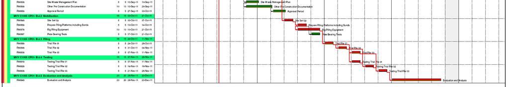
7 3. Construction Sequence 3.1. Introduction Installation and testing of the trail piles is expected to take approximately 8 weeks with a further 4 weeks for evaluation of the results. A Gantt chart showing the proposed construction sequence can be found in Appendix Site Set-up The site supervision team for the works will be experienced in their designated areas of responsibility. The team will ensure the work is competently supervised with respect to health and safety, environment and quality. Detailed risk assessments will be attached to this document for construction issue and should be monitored and updated during these works. A Site Clearance Certificate from the Ministry of Defence (MoD) is required before any work can commence. All personnel will have attended the mandatory Kier Construction site induction and will have been briefed on the contents of the risk assessments and method statement (RAMS), and Control of Substances Hazardous to Health (COSHH) assessments relevant to their operations. The construction site is currently surrounded by a secure 3m high fence to prevent unauthorised access. Owing to the presence of the watercourse known as Weston Mill Creek which runs into Weston Mill Lake along the eastern boundary of the site, special precautions must be taken to prevent pollution of that watercourse in accordance with the Environment Agency s Pollution Prevention Guidance (PPG) 5: Works and maintenance in or near water. These will include: A designated, bunded plant refuelling area situated well away from the stream. Use of biodegradable hydraulic fluid in the piling rig, test rig and any other machinery (e.g. excavator and dumper for piling platform preparation etc). All plant must be inspected daily for fluid leaks and must not be used until any leak is rectified. No plant, materials, labour or debris may be allowed to enter the water. Emergency spill kits must be made available and maintained at all times. A leak-proof skip for waste concrete and concrete wash-out is to be provided. 11/08/2011 Page 7 of 25
8 All site personnel will be briefed on the environmental emergency response procedure. A flow chart depicting the Kier Environmental Incident Response Procedure is show on the following page. In addition Kier Construction Limited (KCL) operates various permit-towork procedures and the following shall be implemented during these activities: Permit to Excavate; and Permit to Load. 11/08/2011 Page 8 of 25
9 3.3. Construction of piling mat Before any penetration of the ground surface, a survey of underground services will be carried out using the site clearance certificate information, Cable Avoidance Tool (CAT) and Ground-Penetrating Radar (GPR). Any services shall be clearly marked using wooden pegs, or other marks. However, it is not envisaged that there will be any underground services in these locations. The site is currently covered in mounds of demolition waste. A 360 o excavator and dumper will be used to create a piling mat at a suitable level and this will be compacted using a twin-drum vibrating roller. No imported material is required to construct the piling mat. These items of plant will be used to remove boring arisings from the pliing area and deposit elsewhere within the site boundary. These quantities will be small and will be levelled and compacted where appropriate. Where the concrete placement may displace groundwater to the surface, this water will be contained to prevent direct run-off into the stream and allowed to settle. The quantity of water displaced is not likely to be large and should disperse quickly. A bund shall be constructed around each set of piles and should consist of a 300mm high bund surrounding the area Piling The test piles shall be set out in positions shown on Drawing QC8223/10 above for the reasons described in Section 2.0. The reaction piles shall be set out in a square formation with the fifth pile in the centre being the test pile. All-hydraulic mast-based rigs will be used for the construction of the castin-situ piles. The rigs are fitted with a rotary boring unit which operates a Kelly-bar (used to transmit the torque from the motor to the boring tool which is fitted to the foot of the Kelly bar). This equipment has been selected because of its versatility in a wide variety of soils including the made-ground at this site location, the alluvial silts and the rock beneath. The rig will impart a vertical load on to the Kelly-bar to improve production in difficult strata and overcome buried obstacles such as reinforced concrete. As the test piling methods will be identical to those currently planned for the permanent piles (subject to validation of test results), the following environmental monitoring will be carried out during installation of test piles. Noise monitoring with respect to the most sensitive receptors i.e. residents on Talbot Gardens and Savage Road. Vibration As explained in previous pages, vibration levels are generally low, but are dependent upon the type of soil or rock. 11/08/2011 Page 9 of 25
 of 0.14 mm/s), they are not expected to cause a problem.")
 effect on buried services or other structures nearby.")
10 Studies of vibration case history data suggest that in general the vibration levels from large diameter rotary bored piling are low and even though they are above the threshold of human perception (Peak Particle Velocity (PPV) of 0.14 mm/s), they are not expected to cause a problem. The distance of more than 60m from the test piles to the nearest sensitive receptors (the flats on Talbot Gardens) means that the vibrations from rotary piling are predicted to be imperceptible by residents, and likewise are not predicted to have any adverse (i.e., potentially damaging) effect on buried services or other structures nearby. Ground gas The recent monitoring of ground gas at borehole BH01 will be supplemented by monitoring the drilling operation for disturbance and production of ground gases. Again, as found with the sequence of monitoring already carried out, it is not expected that significant concentrations or flows of ground gas will be encountered. The piles will be constructed from a platform at existing ground level. The piling rig will be set up in position over the pile centre positions as marked. Safety fencing for edge protection shall be erected around each pile position to prevent falls into the hole until the concrete is poured (e.g. when the auger is removed for the magnetometer). When the rig is set up over the pile position, the auger is screwed into the ground a short distance to loosen the soil at the head of the pile. A length of temporary casing is lowered into the open bore and then rotated into the ground. Additional lengths of casing are added and the spoil inside removed until the casing reaches the bedrock to seal off any unstable ground. The rock socket is then bored out below the casing to the required depth, which may be under water. On completion of the bore, the base is cleaned mechanically. The pile reinforcement cage is lowered to the correct level and restrained. The concrete is placed by a central tremmie pipe to the base of the bore and progressively raised in stages always maintaining a suitable head of concrete until the concrete has displaced all of the water in the bore. Pile concrete is left at ground level. The temporary outer casing is then withdrawn in sections and the concrete topped up as necessary. The photo (right) shows the type of rig proposed for the works. Further photographs and a specification can be found in Appendix 2. The risk of the presence of UXO will be monitored at regular intervals with the use of a Magnetometer (a combined magnetometer and non-magnetic CPT cone). The cone of a magnetometer probe for UXO detection will be 11/08/2011 Page 10 of 25
11 lowered into the augered hole at regular intervals while the magnetometer takes real time readings of the amplitude of the Earth s magnetic field. Buried ferrous items result in localised distortions of the magnetic field. These local disturbances are manifested as anomalies in the data that indicate buried metal objects such as tanks, drums, pipes or bombs. The caesium vapour magnetometer has a detection radius of 2.0m for detecting large items such as a 500 kg bomb. This gives drill-depth intervals of 2m at which times the auger will be removed and the probe lowered to the bottom of the hole for readings. Readings will be recorded. Concrete and reinforcement will be supplied to the test pile specification, not the working pile specification as the testing is required to validate the geotechnics, not the pile integrity. Test cubes should be cast at this stage. Depths Kelly bars can be of single or telescopic construction to reach the required depth. The geotechnical investigations carried out so far give expected depths in the region of 20 to 25m. Boring Tools Boring tools are available to cope with different strata. The range includes general purpose augers, rock augers, boring buckets and coring barrels amongst others. The piles are to be straight sided (i.e. not under-reamed) and 880mm diameter. In suitable strata it is possible to construct a dry bore; in waterbearing strata it is often necessary to progress the bore under flooded conditions, i.e. water, bentonite or polymer. Concrete The detailed pile design will determine the grade of concrete to be used. Concrete grades up to 40N/mm² are common, and higher grades can be used where necessary. Where the pile bore is dry, a hopper with a short tube is used to direct the concrete down the centre of the reinforcement. Under flooded conditions a full-length tremmie pipe is used. In both situations it may be practical to terminate the concrete at a low level so that the tested piles finish at a level below any road construction. It is not practical to remove piles after testing and they cannot be re-used as they are effectively tested to failure. Environmental Impacts and Proposed Mitigation Vibration levels depend very much upon the nature of the subsoils, the distance from structures etc and therefore there are no generic figures for individual rigs. However, vibration data collected from the many and various locations and situations for the proposed rig type gives confidence that vibration levels will be low. Dust levels will similarly be very site specific depending upon the soils being bored and the weather conditions. If necessary, the soils being bored will be damped down to reduce dust potential. On-going monitoring 11/08/2011 Page 11 of 25
12 will be carried out by site personnel on a regular basis to ensure no migration of dust. Noise output from the piling operations can be divided into three main activities: Handling crane under load Boring Shaking spoil off the auger Noise contours associated with these operations and interpretation of the contours are included in Appendix 3 at the end of this document. Noise monitoring of the actual operation will also be carried out. In accordance with Plymouth City Council s Code of Practice for the Control of Pollution and Noise from Demolition and Construction Sites, hours of work will be limited to: Monday Friday: 08:00 to 18:00 Saturday: 08:30 to 13:00 The noise limits within Appendix 2 of Plymouth City Council s Code of Practice will also be adhered to (see Appendix 3 for worst case predicted noise levels). Local residents will be informed of the nature of the work prior to it commencing Testing Before any testing can commence all arisings from augering and any other materials such as the earth bund and spilled concrete must be cleared away, the piling mat trimmed to a flat, level surface and re-compacted to suit testing requirements. Use of small sized graded granular fill (e.g. Type 1) may be necessary to achieve the required surface. The plant employed for this purpose will be a 360 o excavator and a wheeled dumper, both operated by suitably experienced and qualified personnel. Sufficient curing time must be allowed before testing may commence and test cubes crushed to verify concrete strength. The piling is intended for design development / validation and the magnitude of the test loads will be set at the Design Verification Load (DVL) which is the working load plus allowances for soil induced forces (such as skin friction) plus 1.5 times the specified working load (SWL). This equates to just over 2.5 times the working load. Load testing shall be carried out in accordance with the Institution of Civil Engineers (ICE) Specification for Piling and Embedded Retaining Walls. The test rig will be erected using a mobile crane and Mobile Elevated Work Platforms (MEWPs) for access. MEWP operators will be International Powered Access Federation (IPAF) qualified and all occupants of the MEWP basket must be attached to the basket via a full body harness and fixed- 11/08/2011 Page 12 of 25
13 length lanyard. The hydraulic cylinders shall be assembled with the pump operation position as far as reasonably practicable from the test rig. Photographs in Appendix 2 show a typical pile testing rig. Static load tests will be carried out for compression, tension and laterally, and the load applied using adjacent piles for application of the reaction loads. The arrangement of the reaction piles and the test load requirements mean that tension testing is carried out in the same procedure as compression load testing (i.e. on the reaction piles). The loads should be taken to failure so that maximum confidence in the test results can be gained. The deflections and loads will be monitored using load cells and these results will be analysed and interpreted for the purpose of validating/modifying the pile design Traffic During the first week of the proposed works, the plant, equipment and portacabins for office and welfare facilities will be brought to the site. This is likely to result in up to 7 one-way HGV movements (on any one day). On a typical day during piling there are likely to be approximately 5 oneway movements of HGVs (concrete lorries). There are likely to be approximately 12 construction workers on site during the works. Assuming a worst case, that no vehicle sharing takes place, this would amount to up to 12 one-way light vehicle movements per day. 4. Quality All project operations will be controlled by Kier s quality procedures, industry standards and project specific quality control plans as agreed and approved by MVV. Additional controls as required by the piling contractor and approved by Kier/MVV will be required. The quality control plans will define all project documents required including ITP s, all approvals, project hold points, records required, and verifying authorities. 5. Safety All personnel accessing the site will be subject to DRDL and KCL site rules and will wear Personal Protective Equipment (PPE) as required. In addition to the above, all operatives will wear appropriate PPE relevant to the tasks being carried out. These include mandatory long sleeves, long trousers, safety boots, task-specific gloves, safety helmet, and safety glasses. Other task-specific PPE may include disposable overalls, face protection, hearing protection, Wellington boots (for concreting) or full body safety harness where there is a risk of falls from height. 11/08/2011 Page 13 of 25
14 The following Safety Risk Assessments are relevant to the works and will be produced by competent persons and attached to the detailed Method Statement in accordance with the Construction Phase Plan: Initial site setup Manual Handling Piling Working at Height Slips, trips and falls Excavations Power tools and abrasive wheels Working near services (live, redundant and unknown) Working near mobile plant and plant movement COSHH Assessment for all hazardous products. Weil's Disease Lift Plans All personnel will be fully briefed on the safe method of work, via the use of a site specific induction and operation Specific Method And Risk Training (SMART) briefings, prior to the works being carried out. All lifting operations (e.g. lifting of pipes using an excavator equipped with an SLI) will be controlled by the lift supervisor and Suitably Qualified and Experienced Personnel (SQEP) banks-men. Static load testing involves the application of very high loads over an extended period of time. Therefore, when under load the rig is very hazardous and only experienced, specialised personnel should carry out and manage the process. Strict restrictions on access to the testing area will be applied. The site safety and environment will be continually monitored via weekly site inspections as well the continual monitoring as described in the above paragraphs. These inspections are carried out independently of the project management and are recorded. Inspection results will be made available upon request. The Health and Safety Plan will also be continually reviewed, the results recorded and changes implemented. 11/08/2011 Page 14 of 25
15 Appendix 1 Timetable for pile installation, testing and evaluation 11/08/2011 Page 15 of 25

16 11/08/2011 Page 16 of 25
17 Appendix 2 Rig Specification and Photographs 11/08/2011 Page 17 of 25

18 11/08/2011 Page 18 of 25


19 Photographs of a typical piling rig 11/08/2011 Page 19 of 25


20 Photographs of a typical pile testing rig 11/08/2011 Page 20 of 25
21 Appendix 3 Noise Contours 11/08/2011 Page 21 of 25
22 11/08/2011 Page 22 of 25
23 11/08/2011 Page 23 of 25
24 11/08/2011 Page 24 of 25
25 Interpretation of noise contours The following sound power levels for the equipment have been derived from the noise contours: Handling crane under load 99 db(a) Piling rig boring large diameter pile 115 db(a) The noise contours for "shaking spoil off the auger" are LAmax levels, and consequently no sound power levels have been derived. However, based on the contours, the maximum instantaneous levels due to this activity would be 16 db(a) above the steady levels for boring a large diameter pile. Noise levels to all surrounding receptors have been calculated, assuming the piling rig was operating continuously at the 3 test locations in turn. Noise levels to all receptors were at or below 70 db(a). The limit at surrounding sensitive receptors, according to Plymouth City Council Code of Practice for the Control of Pollution and Noise from Demolition and Construction Sites is 70 to 75 db LAeq over a 10 hour working day. Hence, the limit is not exceeded. In fact average noise levels over the day will be significantly less than those calculated as the piling rig will not operate continuously. The LAmax levels due to shaking spoil off auger will be at or below 86 db(a) at surrounding sensitive receptors. The Plymouth City Council limit at surrounding sensitive receptors for a 5 minute period is 86 db LAeq. Hence, this limit will not be exceeded. 11/08/2011 Page 25 of 25
METHOD STATEMENT. MVV O&M GmBH, South West Devon Waste Partnership & Kier Construction Limited. Document No: CMS/ E0788 /003 FOR
 METHOD STATEMENT, South West Devon Waste Partnership & Kier Construction Limited Document No: CMS/ E0788 /003 FOR Construction of Bull Point Access Road DOCUMENT HISTORY DATE ISSUE COMMENTS ORIGINATOR
Oweninny Wind Farm. Oweninny Environmental Impact Statement Appendix 5. Turbine Foundation Construction Method Statement
 Oweninny Wind Farm Oweninny Environmental Impact Statement Appendix 5 Turbine Foundation Construction Method Statement Copyright ESB International Limited, all rights reserved. Farm Contents 1 Introduction
Advantages / Disadvantages of Piling Methods. Continuous Flight Auger (CFA)
") Advantages / Disadvantages of Piling Methods In this Piling Advice Note we will explore the advantages and disadvantages of differing types of piling methods. Continuous Flight Auger (CFA) The pile is
Advantages / Disadvantages of Piling Methods In this Piling Advice Note we will explore the advantages and disadvantages of differing types of piling methods. Continuous Flight Auger (CFA) The pile is
National Occupational Standards for Piling Operations
 National Occupational Standards for Piling Operations Review 2015 As @ 120215 Version 2 Development Legend 1 st and 2 nd NWG - Red 3 rd NWG Green 4 th NWG - Blue 5 th NWG Red underlined 6 th NWG Green
Lesson 2 Substructure. Dr S.Sreenath BSc Engg, MSc Engg, MSc (ICM), MBA, PhD
, MBA, PhD") Lesson 2 Substructure Dr S.Sreenath BSc Engg, MSc Engg, MSc (ICM), MBA, PhD Outline Syllabus 1. Demolition 2. Site problems 3. Substructure 4. Basements 5. Structural Frames 6. Floors 7. External walls
Lesson 2 Substructure Dr S.Sreenath BSc Engg, MSc Engg, MSc (ICM), MBA, PhD Outline Syllabus 1. Demolition 2. Site problems 3. Substructure 4. Basements 5. Structural Frames 6. Floors 7. External walls
Misan University - College of Engineering Civil Engineering Department
 CHAPTER 2 Soil and Excavations Soil investigation including two phases: surface investigation and subsurface investigation Surface investigation involves making a preliminary judgment about the site s
Diaphragm wall Construction
 Diaphragm wall Construction Diaphragm wall is a continuous wall constructed in ground in to facilitate certain construction activities, such as: a) As a retaining wall b) As a cut-off provision to support
1. Introduction Selection of Pile Type Soil Report / Boreholes Obstructions Design and Installation of Piling Mat 3
 Contents 1. Introduction 3 2. Selection of Pile Type 3 3. Soil Report / Boreholes 3 4. Obstructions 3 5. Design and Installation of Piling Mat 3 6. Permit to Dig 4 7. Setting out 4 8. Water 5 9. Attendant
Bi-Directional Static Load Testing of Drilled Shafts
 Supplemental Technical Specification for Bi-Directional Static Load Testing of Drilled Shafts SCDOT Designation: SC-M-712 (9/15) September 2, 2015 1.0 GENERAL This work shall consist of furnishing all
Bi-Directional Static Load Testing of Drilled Shafts
 Supplemental Technical Specification for Bi-Directional Static Load Testing of Drilled Shafts SCDOT Designation: SC-M-712 (01/18) 1.0 GENERAL This work shall consist of furnishing all materials, equipment,
SAFE SYSTEMS FOR PILING OPERATIONS
 SAFE SYSTEMS FOR PILING OPERATIONS TYPE & METHOD OF CONSTRUCTION OF PILE BORED CAST-IN-SITU (BCIS) BCIS WITH CONVENTIONAL RIG BCIS WITH ROTARY RIG DRIVEN CAST-IN-SITU (DCIS) DCIS WITH CONVENTIONAL DP RIG
Drilled Shaft. Inspection. HQ Construction Office HQ Geotechnical Division
 Drilled Shaft Inspection HQ Construction Office HQ Geotechnical Division Drilled Shafts: What are Drilled Shafts Drilled Shaft Construction Challenges of Drilled Shaft Construction The WSDOT SHAFT Special
Technical Data Sheet NEC/GRAN/95:01
 Technical Data Sheet NEC/GRAN/95:01 Installation Guidance Notes Granular Surround Note : These guidance notes refer only to the installation of Granular surround underground tanks. These guidance notes
Rapid Axial Load Testing of Drilled Shafts
 Supplemental Technical Specification for Rapid Axial Load Testing of Drilled Shafts SCDOT Designation: SC-M-712 (9/15) September 4, 2015 1.0 GENERAL This work shall consist of performing a rapid axial
OUTLAW AUTOMATION INC. Safety Management System
 Preparation: Safety Mgr Authority: President Issuing Dept: Safety Page: Page 1 of 6 Purpose The purpose of this program is to provide employees general information for working on owner client or other
Oweninny Wind Farm. Oweninny Environmental Impact Statement Appendix 5B
 Oweninny Wind Farm Oweninny Environmental Impact Statement Appendix 5B Access Tracks, Hardstanding Areas, Electrical Compounds, Borrow Pit And Cable Laying Construction Method Statement Copyright ESB International
METHOD STATEMENT for INSTALLATION OF MICROPILE
 METHOD STATEMENT for INSTALLATION OF MICROPILE A. MATERIAL TO BE USED 1. Grout Grout shall be mixed from Ordinary Portland Cement and clean water free from harmful substances. Usage of other cement which
Walls generally range from 600 to 1500 mm thickness, in wide between 2000 and 3500 mm and can be excavated to depths of 60m or more.
 TECHNOLOGY Diaphragm walls Diaphragm walls are one of the most important technologies of special foundation engineering. A diaphragm wall is constructed using a trench excavated in ground and supported
Implementation of this Special Provision requires a complete understanding of the following documents:
 VIRGINIA DEPARTMENT OF TRANSPORTATION SPECIAL PROVISION FOR Quality Assurance/Quality Control (QA/QC) for the Construction of Deep Foundation Systems for Design-Build and PPTA Contracts November 10, 2009
Field Instruction. All Horizon Power workers who work in and around excavations.
 6.4 Excavation work and directional drilling Purpose This instruction provides the minimum requirements for: All Horizon Power workers who work in and around excavations. All Horizon Power workers who
SPECIFICATION FOR JET GROUTING
 SPECIFICATION FOR JET GROUTING 1.0 GENERAL The Specialist Contractor shall construct jet grout columns of nominal diameter and spacing as specified in the drawing(s) to the requirements of the Contract.
Multi-Institutional Academic Health Science & Research Center Evansville, IN
 SECTION 02370 AUGER CAST PILES PART 1 - GENERAL 1.1 SECTION INCLUDES: The work covered by these specifications consists of furnishing all labor, equipment and materials for the installation of auger cast
Level 2 NVQ Diploma in Piling Operations (Construction)
") Level 2 NVQ Diploma in Piling Operations (Construction) Qualification Specification ProQual 2016 Contents Introduction 3 Qualification profile 3 Qualification Structure 4 Pathway 1 Piling Rig Operator
Level 2 NVQ Diploma in Piling Operations (Construction) Qualification Specification ProQual 2016 Contents Introduction 3 Qualification profile 3 Qualification Structure 4 Pathway 1 Piling Rig Operator
C. Foundation stabilization for pipe and utility structures.
 PART 1 - GENERAL 1.1 SECTION INCLUDES A. Excavating, backfilling, and compacting for utilities, including pipe, structures, and appurtenances. B. Control of water in trenches. C. Foundation stabilization
1. All underground utilities under railroad tracks shall be encased in a larger pipe or conduit called the casing pipe.
 MTS Jack and Bore Design Criteria Note: For the purposes of this Design Criteria and subsequent Construction Notes, the term Jack and Bore is used generically to refer to a number of trenchless construction
PROJECT INFORMATION. 1.1 Site Location. October 4, Jerry Schwab/President 315 Aden Ave., Suite 26 Glendale, CA 91203
 October 4, 2017 Jerry Schwab/President 315 Aden Ave., Suite 26 Glendale, CA 91203 P: 888.900.3823 E: jscwab@schwabeng.com Re: Geotechnical Engineering Letter Report VAMC Bldg 202 Domiciliary C-D Entryway
Health Safety, & Environment
 GROUP SAFETY HEALTH AND ENVIRONMENT MANUAL R.G. Carter Construction Ltd Integrated Management System Section 7 Health Safety, & Environment Issue Manual No. Holders Name: Issue Date: GROUP HEALTH AND SAFETY
SECTION STEEL H PILES. A. Section includes steel H piles embedded into drilled concrete piers.
 SECTION 31 62 16 STEEL H PILES PART 1 - GENERAL 1.01 SCOPE OF WORK A. Section includes steel H piles embedded into drilled concrete piers. B. Furnish all labor, materials, equipment and incidentals required
SECTION XXXXX AGGREGATE PIERS PART 1 - GENERAL
 SECTION XXXXX AGGREGATE PIERS PART 1 - GENERAL 1.1 RELATED DOCUMENTS: Drawings and general provisions of the Contract, including General and Supplementary Conditions and other Division 00 and Division
PILING WORKS FOR PROPOSED NEW BUILDING OF IIT MADRAS RESEARCH PARK AT KANAGAM ROAD, TARAMANI, CHENNAI
 PILING WORKS FOR PROPOSED NEW BUILDING OF IIT MADRAS RESEARCH PARK AT KANAGAM ROAD, TARAMANI, CHENNAI- 600 113 PRE MID MEETING DATE OF MEETING:- 07-5-2013 DECISIONS MADE IN THE MEETING Note : These decisions
REQUIREMENTS FOR SERVICES UNDER THE RAILWAY CORRIDOR (NON-QR SERVICES)
") SYSTEMS AND CAPABILITY TECHNICAL REQUIREMENT NO: MCE-SR-16 ISSUE: Initial DATE: 14-10-2009 PAGE: 1 of 19 REQUIREMENTS FOR SERVICES UNDER THE RAILWAY CORRIDOR (NON-QR SERVICES) ISSUE DATE DESCRIPTION /
SYSTEMS AND CAPABILITY TECHNICAL REQUIREMENT NO: MCE-SR-16 ISSUE: Initial DATE: 14-10-2009 PAGE: 1 of 19 REQUIREMENTS FOR SERVICES UNDER THE RAILWAY CORRIDOR (NON-QR SERVICES) ISSUE DATE DESCRIPTION /
Installation Instructions for Circular Trench Pipes (DN300 DN1200) PD 46 rev D October 2013
 PD 46 rev D October 2013") Installation Instructions for Circular Trench Pipes (DN300 DN1200) October 2013 Page 1 of 7 1. Scope This document gives basic guidance on the installation of Stanton Bonna circular pipes incorporating
Installation Instructions for Circular Trench Pipes (DN300 DN1200) October 2013 Page 1 of 7 1. Scope This document gives basic guidance on the installation of Stanton Bonna circular pipes incorporating
SECTION / ENGINEERED AGGREGATE PIERS (SOIL REINFORCEMENT AND FOUNDATION SYSTEM)
") PART 1 GENERAL 1.01 WORK INCLUDED SECTION 02360 / 31 34 30.13 ENGINEERED AGGREGATE PIERS (SOIL REINFORCEMENT AND FOUNDATION SYSTEM) A. Provide all equipment, material, labor and supervision to design and
PART 1 GENERAL 1.01 WORK INCLUDED SECTION 02360 / 31 34 30.13 ENGINEERED AGGREGATE PIERS (SOIL REINFORCEMENT AND FOUNDATION SYSTEM) A. Provide all equipment, material, labor and supervision to design and
Stage 4 Geotechnical Investigations Information Sheet
 Stage 4 Geotechnical Investigations Information Sheet Geotechnical specialists will use a range of equipment to examine ground conditions by either excavating small shallow test pits of soil, using a mechanical
Construction, Demolition & Excavation Works Doc Reference: DoMN-WHSMS 3.14 Version Number: 2.2
 Purpose This procedure provides guidance to the Diocese of Maitland Newcastle (DoMN), principal contractors and other persons conducting a business or undertaking (PCBU) who commission or carry out construction,
Health & Safety Plan DEMOLITION WORKS: No 2 Substation
 DEMOLITION WORKS: No 2 Substation Revision History Revision Date Section Detail of Amendment By r3a 09/10/14 First Issue JH 17 October 2014 Page 2 Revision 4 Contents 1. Description of Project 1.1. Introduction
Construction Technology B (CON4313)
") 3 - Basement 1 Quick Revision 1.1 Problems arising from basement construction a. Excavation method. b. Surface and ground water control c. Lateral stability of basement excavation. d. Stability of adjoining
3 - Basement 1 Quick Revision 1.1 Problems arising from basement construction a. Excavation method. b. Surface and ground water control c. Lateral stability of basement excavation. d. Stability of adjoining
SCOPE OF WORK FOR PILING JOB
 SCOPE OF WORK FOR PILING JOB 1.0 PURPOSE This document defines the scope of works and specific requirements for the tank pad construction including pile foundation system for the proposed tanks at Wadala
SECTION DRILLED CONCRETE PIERS AND SHAFTS
 1 PART ONE - GENERAL 1.1 COORDINATION SECTION 02466 DRILLED CONCRETE PIERS AND SHAFTS A. The General, Supplementary, and Special Conditions of these specifications shall all be considered as a part of
Site Investigation MUHAMMAD AZRIL HEZMI
 Site Investigation MUHAMMAD AZRIL HEZMI Definition Essential part of the preliminary design workon any important structure in order to provide adequateand reliable geotechnical informationand site condition,
North End and South End Section Hauled Wastewater Receiving Facilities Page 1 Bid Opportunity No
 Hauled Wastewater Receiving Facilities Page 1 Part 1 General 1.1 SECTION INCLUDES.1 Materials and installation for sewage force mains. 1.2 RELATED SECTIONS.1 CW 2110 Watermains and all specifications referenced
This report assesses the outward noise and vibration impact of the proposed development on its surrounding environment.
 8. NOISE AND VIBRATION 8.1 Introduction This report has been prepared by AWN to form part of an EIAR for the proposed residential development at Wonderful Barn, Barnhall, Leixlip. The chapter assesses
204 - EXCAVATION AND BACKFILL FOR STRUCTURES SECTION 204 EXCAVATION AND BACKFILL FOR STRUCTURES
 SECTION 204 EXCAVATION AND BACKFILL FOR STRUCTURES 204.1 DESCRIPTION Excavate for the structures as shown in the Contract Documents. Unless specified otherwise, backfill the completed structures to the
Soil Improvement by Compaction Grouting
 CITY AND COUNTY OF DENVER ENGINEERING DIVISION Wastewater Capital Projects Management Standard Construction Specification 31-3223.12 Soil Improvement by Compaction Grouting Part 1 - General 1.01 Introduction
Lantz-Boggio Architects, P.C LBA Project No
 SECTION 313430- PART 1 GENERAL 1.1 WORK INCLUDED A. Provide all equipment, material, labor and supervision to design and install Engineered Aggregate Piers for the soil reinforcement. Design shall rely
SECTION TRENCHING, BACKFILLING, COMPACTION AND GENERAL GRADING
 PART 1 GENERAL SECTION 02221 TRENCHING, BACKFILLING, COMPACTION AND GENERAL GRADING 1.01 SECTION INCLUDES A. Excavation, dewatering and backfilling with compaction of trenches for pipes, conduits, channels
Excavations and Blind Penetrations into Walls & Floors
 Excavations and Blind Penetrations into Walls & Floors (Instructions for using JLab DIGGING, EXCAVATING, FLOOR/WALL PENETRATION PERMIT REQUEST) Permits are required on JLAB property for any penetrations
SUPPLEMENTAL TECHNICAL SPECIFICATION
 July 14, 2015 HIGH STRAIN DYNAMIC LOAD TESTING OF DRILLED SHAFTS 1.0 GENERAL This work shall consist of performing high-strain dynamic testing using a drop weight loading system on a test drilled shaft
Assalamualaikum & Good Morning (May All Of You Gain A Better Understanding)
") Assalamualaikum & Good Morning (May All Of You Gain A Better Understanding) Always Try To Do The Best In Your Life TYPES OF FOUNDATION TYPES OF FOUNDATION a) Shallow Foundation System i) Spread Foundation
Assalamualaikum & Good Morning (May All Of You Gain A Better Understanding) Always Try To Do The Best In Your Life TYPES OF FOUNDATION TYPES OF FOUNDATION a) Shallow Foundation System i) Spread Foundation
SEMINAR. Introduction to Continuous Flight Auger (CFA) piling Thursday 21/8/2013. Facilitator: Martin Larisch
 piling Thursday 21/8/2013. Facilitator: Martin Larisch") SEMINAR Introduction to Continuous Flight Auger (CFA) piling Thursday 21/8/2013 Facilitator: Martin Larisch 1 Brief History of Piling Contractors, its capabilities and market Introduction to CFA piling
SEMINAR Introduction to Continuous Flight Auger (CFA) piling Thursday 21/8/2013 Facilitator: Martin Larisch 1 Brief History of Piling Contractors, its capabilities and market Introduction to CFA piling
Abu Dhabi EHSMS Regulatory Framework (AD EHSMS RF)
") Abu Dhabi EHSMS Regulatory Framework (AD EHSMS RF) EHS Regulatory Instrument Code of Practice EHS RI - CoP 40.0 False Work (Formwork) Version 2.0 February 2012 ACKNOWLEDGEMENTS With gratitude Abu Dhabi
Abu Dhabi EHSMS Regulatory Framework (AD EHSMS RF) EHS Regulatory Instrument Code of Practice EHS RI - CoP 40.0 False Work (Formwork) Version 2.0 February 2012 ACKNOWLEDGEMENTS With gratitude Abu Dhabi
Level 2 NVQ Diploma in Piling Operations (Construction)
") Level 2 NVQ Diploma in Piling Operations (Construction) Qualification Specification ProQual 2016 Contents Introduction 3 Qualification profile 3 Qualification Structure 4 Pathway 1 Piling Rig Operator
Level 2 NVQ Diploma in Piling Operations (Construction) Qualification Specification ProQual 2016 Contents Introduction 3 Qualification profile 3 Qualification Structure 4 Pathway 1 Piling Rig Operator
B. Subsurface data is available from the Owner. Contractor is urged to carefully analyze the site conditions.
 SECTION 31 23 33 - TRENCHING, BACKFILLING AND COMPACTION PART 1 - GENERAL 1.1 SCOPE A. This Section specifies the requirements for excavating and backfilling for storm sewer, sanitary sewer, water distribution
SAFETY METHOD STATEMENT
 SAFETY METHOD STATEMENT OUR POLICY The safety of our employees and those of our clients is our main priority when carrying out any work on site. This method statement is designed to let you, the client
Construction Method Statement
 Construction Method Statement Planning Application Phase 17 October 2014 for 79-85 Monier Road London E3 2PS Penten Group Ltd 816 Garratt Lane London SW17 0LZ Tel: 020 8772 4040 Description Contents Page
A. Section includes temporary excavation support and protection systems.
 SECTION 31 50 00 - EXCAVATION SUPPORT AND PROTECTION PART 1 - GENERAL 1.1 RELATED DOCUMENTS A. Drawings and general provisions of the Contract, including General and Supplementary Conditions and Division
SECTION DRILLED CONCRETE PIERS AND SHAFTS
 SECTION 31 63 29 PART 1 - GENERAL 1.1 RELATED DOCUMENTS A. Drawings and general provisions of the Contract, including General and Supplementary Conditions and Division 01 Specification Sections, apply
FURTHER TECHNICAL INFORMATION IN RELATION TO THE OPERATIONS OF OUR GROUP
 A. TECHNICAL INFORMATION OF OUR FOUNDATION WORKS The major types of our foundation works (with illustrative diagram, where applicable) are set out below: 1. Bored piles 0.80m 3.5m pile shaft By Grabbing
Civil Engineering Construction I (CBE5031)
") Civil Engineering Construction I (CBE5031) Basement 1 1 Quick Revision 1.1 Problems arising from basement construction a) Excavation method. b) Surface and ground water control c) Lateral stability of
Civil Engineering Construction I (CBE5031) Basement 1 1 Quick Revision 1.1 Problems arising from basement construction a) Excavation method. b) Surface and ground water control c) Lateral stability of
The applicant has estimated a total of vehicle movements per day.
 INSPECTORS REPORT WASTE LICENCE REGISTER NUMBER 147-1 Ashgrove Plant Limited (trading as Ashgrove Recycling) Churchfield Industrial Estate, Cork Recommendation: That a Licence subject to condition be granted
DHANALAKSHMI COLLEGE OF ENGINEERING, CHENNAI DEPARTMENT OF CIVIL ENGINEERING 2 MARK QUESTIONS WITH ANSWERS CE FOUNDATION ENGINEERING UNIT 1
 DHANALAKSHMI COLLEGE OF ENGINEERING, CHENNAI DEPARTMENT OF CIVIL ENGINEERING 2 MARK QUESTIONS WITH ANSWERS CE6502 - FOUNDATION ENGINEERING Subject Code: CE6502 UNIT 1 1. What are the informations obtained
CONSTRUCTION SPECIFICATION FOR FOOTINGS AND PADS FOR ELECTRICAL EQUIPMENT
 ONTARIO PROVINCIAL STANDARD SPECIFICATION METRIC OPSS 616 NOVEMBER 2008 CONSTRUCTION SPECIFICATION FOR FOOTINGS AND PADS FOR ELECTRICAL EQUIPMENT TABLE OF CONTENTS 616.01 SCOPE 616.02 REFERENCES 616.03
GEOTECHNICAL INVESTIGATION PROPOSED OUTFALL LOCATION CITY OF MORGAN S POINT DRAINAGE HARRIS COUNTY, TEXAS REPORT NO
 GEOTECHNICAL INVESTIGATION PROPOSED OUTFALL LOCATION CITY OF MORGAN S POINT DRAINAGE HARRIS COUNTY, TEXAS REPORT NO. 1140198001 Reported to: SIRRUS ENGINEERS, INC. Houston, Texas Submitted by: GEOTEST
National Occupational Standards Development Pack for Sub-Structure Work Occupations (Construction)
") National Occupational Standards Development Pack for Sub-Structure Work Occupations (Construction) NOS WORK 2014 Full suite review (See Standard Template Update 2010 and 2011-13 for full details of generic
National Occupational Standards Development Pack for Sub-Structure Work Occupations (Construction) NOS WORK 2014 Full suite review (See Standard Template Update 2010 and 2011-13 for full details of generic
This specification supplements the requirements of the Occupational Health and Safety Act, and its Regulations.
 SPEC-1100 1/9 1.0 PURPOSE This specification describes the minimum requirements for general grading, excavation of earth, rock and solid slag, embankment construction, ditching, use of explosives, and
RISK ASSESSMENT SHEET
 Task Generic install telecoms equipment Assessment date 3rd October 2017 Location Various Review date 2nd October 2018 Number of staff at work Various Signature 1 Selected locations Works carried out during
SECTION TRENCHING
 SECTION 31 23 17 TRENCHING PART 1 GENERAL 1.1 SUMMARY A. Section Includes: 1. Excavating trenches for utilities and utility structures. 2. Bedding. 3. Backfilling and compacting to subgrade elevations.
* The use of these areas can vary from car park space, where little waterproofing is required through to store rooms or plant rooms where a high
 1 2 Demand for space in cities often makes it essential to use space below buildings. The concept of deep basement technology has been employed since the middle of last century, but is becoming more popular
Compaction and Jet Grouting
 Compaction and Jet Grouting Alan Ringen, PE Senior Vice President Breakthroughs in Tunneling Short Course August 16, 2017 Grouting Principles Geotechnical Grouting: The injection of pumpable fluid materials
Livezeni Coal Washing Plant, Hunedoara County, Design: ICPM Petrosani
 Public Disclosure Authorized Public Disclosure Authorized Public Disclosure Authorized Public Disclosure Authorized Livezeni Coal Washing Plant, Hunedoara County, Design: ICPM Petrosani DESCRIPTION OF
CONSTRUCTION SPECIFICATION FOR PIPELINE AND UTILITY INSTALLATION IN SOIL BY HORIZONTAL DIRECTIONAL DRILLING
 ONTARIO PROVINCIAL STANDARD SPECIFICATION METRIC OPSS 450 NOVEMBER 2002 CONSTRUCTION SPECIFICATION FOR PIPELINE AND UTILITY INSTALLATION IN SOIL BY HORIZONTAL DIRECTIONAL DRILLING TABLE OF CONTENTS 450.01
11 HYDROLOGY, HYDROGEOLOGY AND DRAINAGE
 11 HYDROLOGY, HYDROGEOLOGY AND DRAINAGE 11.1 introduction 11.1.1 The objective of this section and the statements presented is to assess the existing hydrological and hydrogeological conditions to understand
204 - EXCAVATION AND BACKFILL FOR STRUCTURES SECTION 204 EXCAVATION AND BACKFILL FOR STRUCTURES. Granular Backfill (Wingwalls) (Set Price)
 (Set Price)") SECTION 204 EXCAVATION AND BACKFILL FOR STRUCTURES 204.1 DESCRIPTION Excavate for the structures as shown in the Contract Documents. Unless specified otherwise, backfill the completed structures to the
SECTION 204 EXCAVATION AND BACKFILL FOR STRUCTURES 204.1 DESCRIPTION Excavate for the structures as shown in the Contract Documents. Unless specified otherwise, backfill the completed structures to the
PILING PART-VI CONSTRUCTION AND INSTALLATION OF RCC BORED CAST IN-SITU PILES
 Page 1 of 8 PILING PART-VI OF RCC BORED CAST IN-SITU PILES REV. NO. PRAPARED APPROVED DATE 00 Marina P Mishra COPYRIGHT AND CONFIDENTAL The information on this document is the property of BHARAT HEVY ELECTRICAL
DEMOLITION TRADE SPECIFICATION
 DEMOLITION TRADE SPECIFICATION GENERAL a) BDW Trading Limited Barratt Homes and David Wilson Homes are all trading names of BDW Trading Limited the Company. b) Site Condition The Contractor is to examine
REPORT OF GEOTECHNICAL EXPLORATION WEST MARJORY AVENUE TAMPA, FLORIDA
 REPORT OF GEOTECHNICAL EXPLORATION WEST MARJORY AVENUE TAMPA, FLORIDA AREHNA PROJECT NO. B-15-008 March 11, 2015 Prepared For: City of Tampa Stormwater Division 306 W. Jackson Street, 6N Tampa, Florida
LOSTOCK SUSTAINABLE ENERGY PLANT VARIATION OF CONSENT UNDER SECTION 36C OF THE ELECTRICITY ACT 1989
 DOCUMENT 8b LOSTOCK SUSTAINABLE ENERGY PLANT VARIATION OF CONSENT UNDER SECTION 36C OF THE ELECTRICITY ACT 1989 DIRECTION UNDER SECTION 90(2ZA) OF THE TOWN AND COUNTRY PLANNING ACT 1990 TO VARY THE CONDITIONS
VERIFICATION OF GEOTECHNICAL GROUTING- STRATEGIES AND PLANNING. Michael J. Byle, D.GE, F. ASCE
 VERIFICATION OF GEOTECHNICAL GROUTING- STRATEGIES AND PLANNING Michael J. Byle, D.GE, F. ASCE Verification of Geotechnical Grouting was published By the ASCE Committee on Grouting in 1995 It is still available
Selection of Proprietary Shoring Equipment
 CPA Safety Guidance Selection of Proprietary Shoring Equipment Introduction Every contractor involved with groundwork must ensure the safe support of trenches and excavations as part of their risk assessment.
Pipe Jacking/Microtunnelling. Dr. Mark Knight. Centre for Advancement of Trenchless Technologies (CATT) University of Waterloo.
 University of Waterloo.") Pipe Jacking/Microtunnelling Dr. Mark Knight Centre for Advancement of Trenchless Technologies (CATT) University of Waterloo 1 New Installations New Installations Non-Steering Methods Steering Methods
Pipe Jacking/Microtunnelling Dr. Mark Knight Centre for Advancement of Trenchless Technologies (CATT) University of Waterloo 1 New Installations New Installations Non-Steering Methods Steering Methods
CONSTRUCTION DUST AND NOISE MONITORING REPORT OFFICE DEVELOPMENT EXAMPLE LTD RP
 CONSTRUCTION DUST AND NOISE MONITORING REPORT OFFICE DEVELOPMENT EXAMPLE LTD RP01-19999 CONSTRUCTION DUST AND NOISE MONITORING REPORT PROJECT: OFFICE DEVELOPMENT CLIENT: EXAMPLE LTD CLIENT ADDRESS: EXAMPLE
ROTARY DRILLING TECHNIQUES LARGE DIAMETER
 INTRODUCTION This paper presents details about large diameter rotary drilling techniques typically employed in the civil engineering industry. These techniques have also been applied to the resources /
CONSTRUCTION SPECIFICATION FOR NOISE BARRIER SYSTEMS
 ONTARIO PROVINCIAL STANDARD SPECIFICATION METRIC OPSS 760 NOVEMBER 2014 CONSTRUCTION SPECIFICATION FOR NOISE BARRIER SYSTEMS TABLE OF CONTENTS 760.01 SCOPE 760.02 REFERENCES 760.03 DEFINITIONS 760.04 DESIGN
The Technical and Contractual Matters of Bored Piling Works. By Wallace Yeung Vibro (H.K.) Ltd.
 Ltd.") The Technical and Contractual Matters of Bored Piling Works By Wallace Yeung Vibro (H.K.) Ltd. What is large diameter bored pile? How to construct a large diameter bored pile? Its advantages and limitation
The Technical and Contractual Matters of Bored Piling Works By Wallace Yeung Vibro (H.K.) Ltd. What is large diameter bored pile? How to construct a large diameter bored pile? Its advantages and limitation
SECTION EARTHWORK; EXCAVATION, FILLING AND GRADING. A. Excavating soil and other material for surface improvements.
 SECTION 31 20 00 PART 1 - GENERAL 1.1 SECTION INCLUDES A. Excavating soil and other material for surface improvements. B. Excavating soil and other material for drainage basins. C. Placing fill. D. Compaction
ITEM 416 DRILLED SHAFT FOUNDATIONS Materials. All materials shall conform to the requirements of the pertinent items as follows:
 ITEM 416 DRILLED SHAFT FOUNDATIONS 416.1. Description. This Item shall govern for the construction of foundations consisting of reinforced concrete drilled shafts and/or nonreinforced concrete drilled
Underground Exhaust System
 Operation and Maintenance Manual Underground Exhaust MONOXIVENT - SOURCE CAPTURE SYSTEMS - info@ Oct. - 2015 Underground Duct Construction Standards 1. Dig trench depth to allow for minimum distance from
SECTION A1 EXCAVATION AND BACKFILL GENERAL
 SECTION A1 EXCAVATION AND BACKFILL GENERAL The work under this section shall include all excavation to such width and depth as shown on the drawings, specified herein, or ordered by the Engineer. Such
Excavation. Stages. Surprises
 Excavation Stages Layout the excavation Strip the topsoil within building lines - store separately Begin excavation Hit water - de-water Slope sides of excavation according to the angle of repose for the
UNDERGROUND UTILITY CONTRACTORS GENERAL TRADE KNOWLEDGE EXAMINATION CONTENT INFORMATION
 UNDERGROUND UTILITY CONTRACTORS GENERAL TRADE KNOWLEDGE EXAMINATION CONTENT INFORMATION Effective September 9, 2014 The General Trade Knowledge portion of the examination is administered daily in Computer
K.Construction Scotland LTD
 K.Construction Scotland LTD Leith, Edinburgh, EH6 5NA, Scotland, U.K Tel: 0131-554-0514 Email: contact@kconstructionltd.com Company Number: SC288209 VAT number: GB870618611, Method Statement For the Refurbishment
Electrical Conductivity & Hydraulic Profiling. The Combining of Two Subsurface Investigation Methods (With More to Come)
") Electrical Conductivity & Hydraulic Profiling The Combining of Two Subsurface Investigation Methods (With More to Come) How has field work been progressing? Split Spoon and Standard Penetration Testing
Electrical Conductivity & Hydraulic Profiling The Combining of Two Subsurface Investigation Methods (With More to Come) How has field work been progressing? Split Spoon and Standard Penetration Testing
DOORNVALLEI EXT 5 & 6
 DOORNVALLEI EXT 5 & 6 Proposed township establishment on portion 107 the farm Doornkloof 391 JR Sewer Pipe Crossings - Sesmylspruit Construction Method Statement April 2016 Revision 3 PREPARED FOR: PREPARED
Level 2 NVQ Diploma in Directional Drilling Operations (Construction)
") (Construction) Qualification Specification ProQual 2016 Contents Page Introduction 3 Qualification profile 3 Qualification Structure 4 Centre requirements 7 Support for candidates 7 Links to National Standards
(Construction) Qualification Specification ProQual 2016 Contents Page Introduction 3 Qualification profile 3 Qualification Structure 4 Centre requirements 7 Support for candidates 7 Links to National Standards
Level 2 NVQ Diploma in Construction Operations and Civil Engineering Services Construction Operations (Construction)
") Civil Engineering Services Construction Operations (Construction) Qualification Specification ProQual 2017 Contents Page Introduction 3 Qualification profile 4 Qualification structure 5 Centre requirements
Civil Engineering Services Construction Operations (Construction) Qualification Specification ProQual 2017 Contents Page Introduction 3 Qualification profile 4 Qualification structure 5 Centre requirements
CONSTRUCTION SPECIFICATION FOR PIPELINE AND UTILITY INSTALLATION IN SOIL BY HORIZONTAL DIRECTIONAL DRILLING
 ONTARIO PROVINCIAL STANDARD SPECIFICATION METRIC OPSS 450 NOVEMBER 2O12 CONSTRUCTION SPECIFICATION FOR PIPELINE AND UTILITY INSTALLATION IN SOIL BY HORIZONTAL DIRECTIONAL DRILLING TABLE OF CONTENTS 450.01
SECTION DUCTILE IRON PILES
 SECTION 31 66 13 DUCTILE IRON PILES PART 1 - GENERAL 1.1 GENERAL REQUIREMENTS A. Work of this Section, as shown or specified, shall be in accordance with the requirements of the Contract Documents. B.
7. Completing the Well s Structure
 7. Completing the Well s Structure 7. Completing the Well s Structure Chapter Table of Contents Chapter Table of Contents Chapter Description... 5 Regulatory Requirements Completing the Well s Structure...
DEFINITIONS. A shallow bored hole under the derrick substructure in which the kelly is temporarily stored during tripping operations.
 DEFINITIONS 1. Conductor Hole A large diameter hole bored to facilitate steel pipe. May be cemented in place to allow conventional oil and gas well drilling operations,and also allows fluid returns to