Report Issued: September 21, 2016 Revision 0
|
|
|
- Jessie Carpenter
- 5 years ago
- Views:
Transcription


1 ALLIANT ENERGY Wisconsin Power and Light Company Edgewater Generating Station CCR SURFACE IMPOUNDMENT SAFETY FACTOR ASSESSMENT Report Issued: September 21, 2016 Revision 0
2 EXECUTIVE SUMMARY This Safety Factor Assessment (Report) is prepared in accordance with the requirements of the United States Environmental Protection Agency (USEPA) published Final Rule for Hazardous and Solid Waste Management System Disposal of Coal Combustion Residual (CCR) from Electric Utilities (40 CFR Parts 257 and 261, also known as the CCR Rule) published on April 17, 2015 and effective October 19, This Report assesses the safety factors of each CCR unit at Edgewater Generating Station in Sheboygan, WI in accordance with (b) and (e) of the CCR Rule. For purposes of this Report, CCR unit refers to existing CCR surface impoundments. Primarily, this Report is focused on assessing if each CCR surface impoundment achieves the minimum safety factors, which include: Static factor of safety under long-term, maximum storage pool loading condition, Static factor of safety under the maximum surcharge pool loading condition, Seismic factor of safety; and, Post-Liquefaction factor of safety for embankments constructed of soils that have susceptibility to liquefaction. Wisconsin Power and Light Company Edgewater Generating Station Safety Factor Assessment September 21, 2016 i
3 Table of Contents 1 INTRODUCTION CCR Rule Applicability Safety Factor Assessment Applicability FACILITY DESCRIPTION EDG Slag Pond EDG North A-Pond EDG South A-Pond EDG B-Pond SAFETY FACTOR ASSESSMENT (e) Safety Factor Assessment Methods Soil Conditions in and under the impoundments Design water surface in impoundments maximum normal pool and maximum pool under design inflow storm Selection of Seismic Design Parameters and Description of Method Liquefaction Assessment Method and Parameters EDG Slag Pond Static Safety Factor Assessment Under Maximum Storage Pool Loading (e)(1)(i) Static Safety Factor Assessment Under Maximum Surcharge Pool Loading (e)(1)(ii) Seismic Safety Factor Assessment (e)(1)(iii) Liquefaction Safety Factor Assessment (e)(1)(iv) EDG North A-Pond Static Safety Factor Assessment Under Maximum Storage Pool Loading (e)(1)(i) Static Safety Factor Assessment Under Maximum Surcharge Pool Loading (e)(1)(ii) Seismic Safety Factor Assessment (e)(1)(iii) Liquefaction Safety Factor Assessment (e)(1)(iv) EDG South A-Pond Static Safety Factor Assessment Under Maximum Storage Pool Loading (e)(1)(i) Static Safety Factor Assessment Under Maximum Surcharge Pool Loading (e)(1)(ii) Seismic Safety Factor Assessment (e)(1)(iii) Liquefaction Safety Factor Assessment (e)(1)(iv) EDG B-Pond Static Safety Factor Assessment Under Maximum Storage Pool Loading (e)(1)(i) Static Safety Factor Assessment Under Maximum Surcharge Pool Loading (e)(1)(ii) Seismic Safety Factor Assessment (e)(1)(iii) Liquefaction Safety Factor Assessment (e)(1)(iv) Wisconsin Power and Light Company Edgewater Generating Station Safety Factor Assessment September 21, 2016 ii
4 4 RESULTS SUMMARY QUALIFIED PROFESSIONAL ENGINEER CERTIFICATION Figures Figure 1: Site Location Figure 2: Soil Boring and Cross-Section Locations Figure 3 Analysis Cross-Sections EDG B-Pond and EDG South A-Pond Figure 4 Analysis Cross-Sections EDG North A-Pond and EDG Slag Pond Figure 5 Cross-Sections at Borings R and Q (Deep borings showing silt layer) Appendix A: Soil Boring Logs Appendix B: Soil Strength Properties Appendix C Earthquake and Liquefaction Analysis Appendix D Slope Stability Analysis Appendices Wisconsin Power and Light Company Edgewater Generating Station Safety Factor Assessment September 21, 2016 iii
5 1 INTRODUCTION The owner or operator of the Coal Combustion Residual (CCR) unit must conduct an initial and periodic safety factor assessments to determine if each CCR surface impoundment achieves the minimum safety factors, which include: Static factor of safety under long-term, maximum storage pool loading condition, Static factor of safety under the maximum surcharge pool loading condition, Seismic factor of safety; and, Post-Liquefaction factor of safety for embankments constructed of soils that have susceptibility to liquefaction. This Report has been prepared in accordance with the requirements of (b) and (e) of the CCR Rule. 1.1 CCR Rule Applicability The CCR Rule requires a periodic safety factor assessment by a qualified professional engineer (PE) for existing CCR surface impoundments with a height of 5 feet or more and a storage volume of 20 acre-feet or more; or the existing CCR surface impoundment has a height of 20 feet or more. 1.2 Safety Factor Assessment Applicability The Edgewater Generating Station (EDG) in Sheboygan, WI (Figure 1) has four existing CCR surface impoundments, identified as follows: EDG Slag Pond EDG North A-Pond EDG South A-Pond EDG B-Pond Each of the identified existing CCR surface impoundments meet the requirements of (b)(1) and/or (b)(2), they are subject to the periodic safety factor assessment requirements of (e) of the CCR Rule. Wisconsin Power and Light Company Edgewater Generating Station Safety Factor Assessment September 21,
6 2 FACILITY DESCRIPTION EDG is located on the south edge of the City of Sheboygan, Wisconsin along the western shore of Lake Michigan in Sheboygan County, at 3739 Lakeshore Drive, Sheboygan, Wisconsin (Figure 1). EDG is a fossil-fueled electric generating station that initiated operations in EDG consists of two steam electric generating units (Unit 4 and Unit 5). A third steam electric generating unit (Unit 3) was removed from service in Sub-bituminous coal is the primary fuel used at EDG for producing steam. The burning of coal produces CCR byproducts. The CCR at EDG is categorized into five types: precipitator fly ash, slag, bottom ash, economizer ash, and scrubber byproducts. The Unit 4 precipitator fly ash is collected by Unit 4 s electrostatic precipitators and sent to an on-site storage silo located southwest of the generating plant. The precipitator fly ash is then transported off-site for either beneficial reuse or for disposal at the EDG I-43 CCR landfill. The Unit 5 precipitator fly ash is collected by Unit 5 s electrostatic precipitators and sent to a separate on-site storage silo located southwest of the generating plant. Unit 5 s precipitator fly ash is then transported off-site for beneficial reuse or for disposal at the EDG I-43 CCR landfill.. The slag at EDG is produced from Unit 4 and is sluiced from the generating plant to a surface impoundment identified as the EDG Slag Pond (Figure 2). The EDG Slag Pond is located southwest of the generating plant. Byproducts from the circulating dry scrubber (CDS) system are transported offsite for disposal at the EDG I-43 CCR Landfill. General Facility Information: Date of Initial Facility Operations: 1930 WPDES Permit Number: WI Latitude / Longitude: , Wisconsin Power and Light Company Edgewater Generating Station Safety Factor Assessment September 21,
7 Nameplate Ratings: Unit 1 (Retired) Unit 2 (Retired) Unit 3 (Retired) Unit 4351 MW Unit 5414 MW 2.1 EDG Slag Pond The EDG Slag Pond is located southwest of the generating plant and north of the EDG North A-Pond. The EDG Slag Pond receives influent flow from the generating plant via the Unit 4 boiler slag tanks. The water-slag slurry discharges into the southwest portion of the EDG Slag Pond. The slag is dredged out of the EDG Slag Pond and stockpiled in a containerized area adjacent to the existing CCR surface impoundment for dewatering. The slag is then screened to separate the coarsely graded material from the finely graded material prior to being transported off-site for beneficial reuse. The water in the EDG Slag Pond flows to the southwest where it gravity flows through a V-notch weir and through a four feet wide concrete structure into a 48-inch diameter corrugated metal pipe. The water from the EDG Slag Pond, which combines with flows from the EDG North A- Pond and EDG South A-Pond in the 48-inch diameter corrugated metal pipe, flows to the south into the northwest corner of the EDG B-Pond. The surface area of the EDG Slag Pond is approximately 2.2 acres and has an embankment height of approximately 12 feet from the crest to the toe of the downstream slope. The interior storage depth of the EDG Slag Pond is approximately 17 feet. The total volume of impounded CCR and water within the EDG Slag Pond is approximately 47,000 cubic yards. 2.2 EDG North A-Pond The EDG North A-Pond is located southwest of the generating plant and south of the EDG Slag Pond. Historically, the EDG North A-Pond has received influent flows from the surge tank. Water in the surge tank includes excess process water from the Unit 5 hydrobin, steam water treatment reject water, and water from the facility floor drains. Therefore, the EDG North A-Pond has likely received residual bottom ash from the Wisconsin Power and Light Company Edgewater Generating Station Safety Factor Assessment September 21,
8 hydrobin system, de minimis quantities of fly ash from routine maintenance operations, coal fines, and other materials from the plant floor drains. The water was pumped from the surge tank to the EDG North A-Pond via a 10-inch diameter steel pipe. The steel pipe, at a location northeast of the EDG North A-Pond, splits into two separate 10-inch diameter pipes. Each pipe then discharged into the northeast corner of both the EDG North A-Pond and EDG South A-Pond. Currently, EDG North A-Pond does not receive operational process discharges from the generating plant, although it still has the ability to be routed to the EDG North A-Pond. Previously, water within the EDG North A-Pond flowed to the west. The EDG North A- Pond discharge consists of an 18-inch diameter corrugated plastic pipe located in the southwest corner of the existing CCR surface impoundment. The water would flow through the corrugated plastic pipe to the west into a concrete sluice box. The water within the sluice box flows through a Parshall flume prior to discharging into a 48-inch diameter corrugated metal pipe, which also receives influent flow from the EDG Slag Pond and EDG South A-Pond, prior to gravity flowing to the south into the northwest corner of the EDG B-Pond. Presently, no water within the EDG North A-Pond discharges through the 18-inch diameter corrugated plastic pipe as the pipe has been plugged. The surface area of the EDG North A-Pond is approximately 2.2 acres and has an embankment height of approximately 18 feet from the crest to the toe of the downstream slope. The interior storage depth of the EDG Secondary Ash Pond is approximately 21 feet. The total volume of impounded CCR and water within the EDG North A-Pond is approximately 73,000 cubic yards. 2.3 EDG South A-Pond The EDG South A-Pond is located southwest of the generating plant and south of the EDG North A-Pond. As currently configured, the EDG South A-Pond receives influent flows from the surge tank. Water in the surge tank includes excess process water from the Unit 5 hydrobin, steam water treatment reject water, and water from the facility floor Wisconsin Power and Light Company Edgewater Generating Station Safety Factor Assessment September 21,
9 drains. Therefore, the EDG North A-Pond has likely received residual bottom ash from the hydrobin system, de minimis quantities of fly ash from routine maintenance operations, coal fines, and other materials from the plant floor drains. The water is pumped from the surge tank to the EDG South A-Pond via a 10-inch diameter steel pipe. The steel pipe, at a location northeast of the EDG North A-Pond, splits into two separate 10-inch diameter pipes. Each pipe then discharges into the northeast corner of both the EDG North A-Pond and EDG South A-Pond. Note, the EDG North A-Pond no longer receives operational process flows from the generating plant. The water within the EDG South A-Pond flows to the west. The EDG South A-Pond consists of an 18-inch diameter corrugated plastic pipe located in the northwest corner of the existing CCR surface impoundment. The water flows through the corrugated plastic pipe to the west into a concrete sluice box. The water within the sluice box flows through a Parshall flume prior to discharging into a 48-inch diameter corrugated metal pipe, which also receives influent flow from the EDG Slag Pond, prior to gravity flowing to the south into the northwest corner of the EDG B-Pond. The surface area of the EDG South A-Pond is approximately 2.2 acres and has an embankment height of approximately 18 feet from the crest to the toe of the downstream slope. The interior storage depth of the EDG South A-Pond is approximately 25 feet. The total volume of impounded CCR and water within the EDG South A-Pond is approximately 90,500 cubic yards. 2.4 EDG B-Pond The EDG B-Pond is located southwest of the generating plant and south of the EDG South A-Pond. The EDG B-Pond receives influent flow via a 48-inch diameter corrugated metal pipe from the EDG Slag Pond and EDG South A-Pond. Additionally, the EDG B-Pond receives storm water drainage from a part of the closed ash landfill west of the EDG B- Pond. The storm water from the closed ash landfill discharges into the west side of the EDG B-Pond via a small corrugated plastic pipe. Wisconsin Power and Light Company Edgewater Generating Station Safety Factor Assessment September 21,
10 The water in the EDG B-Pond flows to the east through an overflow weir wet well structure, Figure 2. The elevated weir prevents CCR that has settled in the EDG B-Pond from flowing out of the impoundment. The water gravity flows to the east through a 24- inch diameter corrugated metal pipe where it discharges into the west side of the EDG C-Pond. The water in the EDG C-Pond gravity flows to the east into the EDG F-Pond. The water in the EDG F-Pond flows through the facility s Wisconsin Pollution Discharge Elimination System (WPDES) Outfall 004 and discharges into Lake Michigan. As determined by WPL, process water discharging from the EDG B-Pond does not contain a significant quantity of CCR, and downstream impoundments contain only de minimis quantities of CCR. The water surface area of the EDG B-Pond is approximately 1.9 acres and has an embankment height of approximately 24 feet from the crest to the toe of the downstream slope in EDG C-Pond. The interior storage depth of the EDG B-Pond is approximately 15 feet. The total volume of impounded CCR and water within the EDG B-Pond is approximately 46,500 cubic yards. Wisconsin Power and Light Company Edgewater Generating Station Safety Factor Assessment September 21,
11 3 SAFETY FACTOR ASSESSMENT (e) This Report documents if each CCR surface impoundment achieves the minimum safety factors, which are identified on the table below. Safety Factor Assessment Minimum Safety Factor Static Safety Factor Under Maximum Storage Pool Loading 1.50 Static Safety Factor Under Maximum Surcharge Pool Loading 1.40 Seismic Safety Factor 1.00 Liquefaction Safety Factor Safety Factor Assessment Methods The safety factor assessment is completed with the two dimensional limit-equilibrium slope stability analyses program STABL5M (1996) 1. The program analyzes many potential failure circles or block slides by random generation of failure surfaces using the toe and crest search boundaries set for each analysis. The solution occurs by balancing the resisting forces along the failure plane due to the Mohr-Columb failure strength parameters of friction angle and cohesion. The gravity driving forces are divided by the resisting forces to produce a safety factor for the slope. The minimum of hundreds of searches is presented as the applicable safety factor. There are both total stress and effective stress friction angle and cohesion values for clay. For the total stress case clay has only cohesion. For effective stress clay has both cohesion and friction angle. When clay receives a load that is applied only briefly (i.e., earthquake or high water), it responds as a total stress soil. For long term loadings such as normal water elevation, the clay resistance to failure is based on effective stress parameters. Because effective stress clay parameters are not readily available from the soil testing and because the total stress parameters for compacted and over consolidated clay yield a 1 STABL User Manual by Ronald A. Siegal, Purdue University, June 4, 1975 and STABL5 The Spencer Method of Slices: Final Report by J. R. Carpenter, Purdue University, August 28, 1985 Wisconsin Power and Light Company Edgewater Generating Station Safety Factor Assessment September 21,
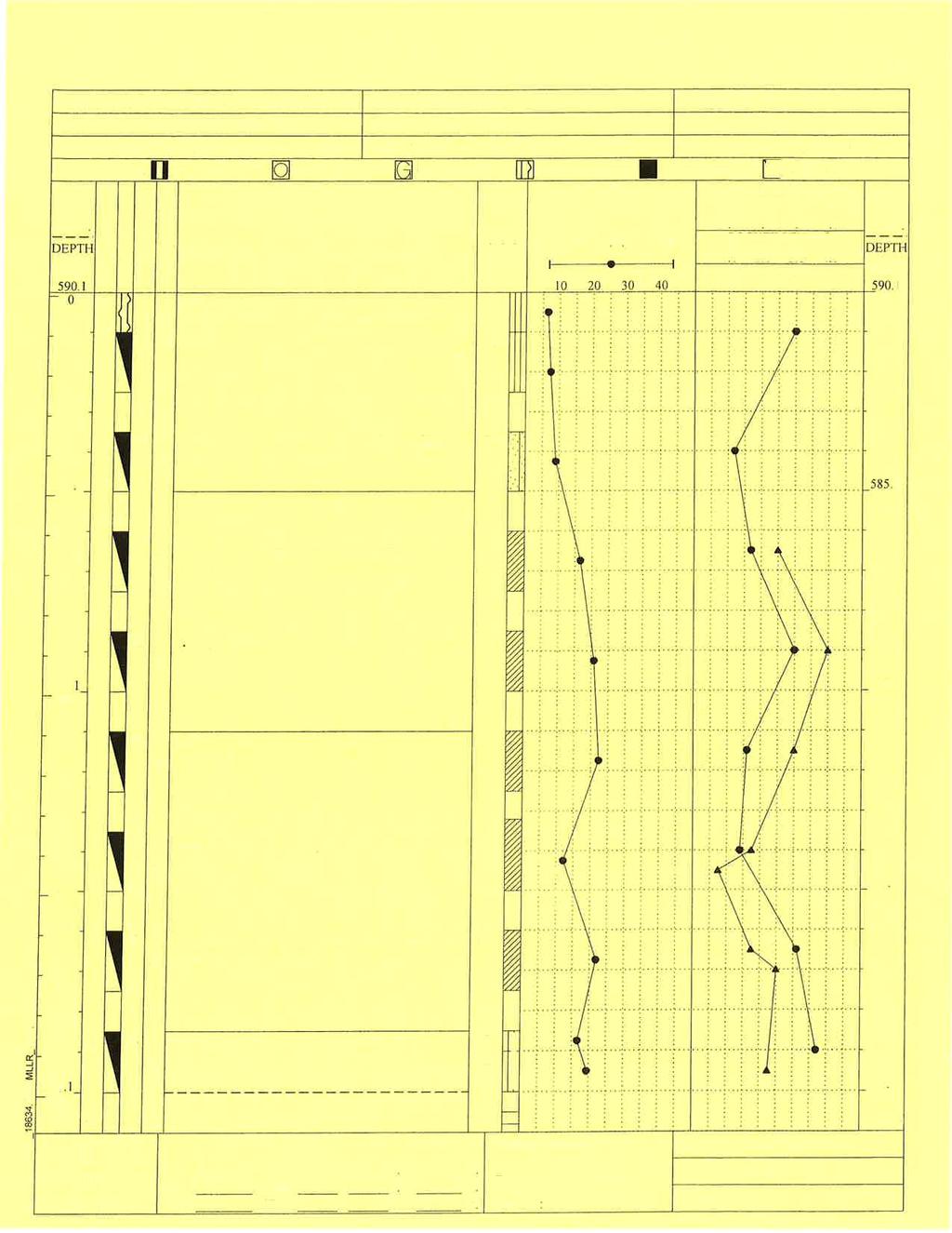
12 conservative answer for safety factor, the static analysis with normal operating water elevation is performed with the total stress parameters for the clay components in the embankments Soil Conditions in and under the impoundments In December of 2010, Miller Engineers and Scientists installed thirteen soil borings through the embankments of the EDG CCR impoundments. The locations of the borings and cross-sections of the embankments are shown on Figures 2 through 5. The topography of the embankments was also determined in late Since no substantial changes have occurred at the EDG CCR impoundments since 2010, the 2010 investigative results combined with the present impoundment operating conditions (normal water elevations) are used in the stability analysis. The soil boring logs, Appendix A, indicate that the embankments of the EDG CCR impoundments are constructed of very stiff to stiff compacted clay (CL). The embankment foundation is medium dense to very loose silt starting at elevation 586 feet and extending to a medium stiff clay at an elevation of 560 to 569 feet, Borings E, Q, and R in Appendix A. The borings on other cross-sections are not as deep but generally show the same subsurface layers with the exception of borings on the south incised slope of the impoundments which indicate the presence of CCR in the slope. The properties of the clay in the embankment and the deeper natural clays used in the stability assessment are based on the pocket penetrometer readings shown on the boring logs. The cohesion values range from 1,500 to 4,000 psf. The internal angle of friction for the medium dense to very loose silt layer under the embankment is selected based on Figure 3-7 Navfacs DM-7, Appendix B 2. The internal friction angle is 27 where the silt is very loose to 30 where the silt is medium dense. 2 Naval Facilities Engineering Command, Design Manual Soil Mechanics, Foundations, and Earth Structures, NAVFAC DM-7, March 1971 Wisconsin Power and Light Company Edgewater Generating Station Safety Factor Assessment September 21,
13 The upper layer of the embankment for the EDG South A-Pond is dense bottom ash a coarse grained soil and is assigned an internal angle of friction of 37. Loose saturated CCR behind the embankments is assigned an internal angle of friction of 27 the same as for the very loose silt foundation layer Design water surface in impoundments maximum normal pool and maximum pool under design inflow storm The EDG CCR impoundments each have specific functions in the handling of process water from the EDG Plant. The Slag Pond is the settling basin for the coarse slag from the Unit 4 boiler, EDG South A-Pond is the settling basin for various sumps and boiler feed water conditioning reject, and EDG B-Pond is the final settling basin for the fines that do not get deposited in the other impoundments. The total process water flow from the plant is 4.8 MGD. In addition each impoundment does accept a small watershed area from the slope to the south of the impoundments on the closed landfill site. The process water flows and the rainfall from a 1,000 year Type II SCS storm distribution are routed through the impoundments to create a maximum pool for each impoundment during the design storm. The normal operating flows in 2016 and the maximum storm pool are: CCR Pond Normal Pool Water Elevation (feet) Maximum Pool Elevation (feet) Embankment Crest Elevation (feet) EDG Slag pond EDG North A-Pond EDG South A-Pond EDG B-Pond Selection of Seismic Design Parameters and Description of Method The design earthquake ground acceleration is selected from the United States Geologic Survey (USGS) detailed seismic design maps based on the latitude and longitude of the EDG. The peak ground acceleration (PGA) value is selected for a 2% probability of exceedance in 50 years (2,500 year return period) as required by Since the site soils are clay with cohesion greater than 1,000 psf, excepting the silt layer, and extend to Wisconsin Power and Light Company Edgewater Generating Station Safety Factor Assessment September 21,
14 bedrock at 130 feet 3, the site class as defined in the 2009 International Building Code is Site Class D. For Site Class D the ground surface PGA for slope stability and liquefaction assessment is 0.05g, Appendix C Liquefaction Assessment Method and Parameters Certain soils may have zero effective stress (liquefaction) during an earthquake or from static shear of a saturated embankment slope. Soils that will liquefy include loose or very loose uniform fine sand or silt, and low plasticity clay (plastic index of less than 12). The liquefaction resistance of a soil is based on its strength and effective confining stress. The strength of the saturated silt is measured by the SPT results shown on the borings in Appendix A. Some of the site clay has plastic index less than 12 as shown on Figures 3 through 5. However the clay is stiff or very stiff and not subject to liquefaction. The test results for Boring E located on the north embankment of EDG B-Pond, Figure 2 at the highest embankment height and with the lowest silt strength measured indicate the silt is very loose (SPT blowcount less than 5 blows per foot). The simplified assessment of liquefaction procedure as first proposed by Seed and most recently updated and published by Idriss and Boulanger 4 is used to assess the potential for liquefaction of the silt. The procedure uses the strengths determined by the SPT test adjusted to normalize for overburden pressure and for fines content to determine the cyclic resistance ratio for the soil at earthquake magnitude 7.5 and at 1 atmosphere pressure. The cyclic resistance ratio is then adjusted for the actual earthquake magnitude of the design event which is 7.7 for a New Madrid Fault source earthquake 5. The cyclic stress ratio caused by the design surface PGA is then used to determine the actual cyclic 3 Ground water well records on file with the State of Wisconsin for area near EDG 4 Idriss I. M. and R. W. Boulanger, Soil Liquefaction During Earthquakes, EERI MNO-12, Elnashi et al, Impact of Earthquakes on the Central USA, FEMA Report 8-02, Mid-American Earthquake Center, 2002 Wisconsin Power and Light Company Edgewater Generating Station Safety Factor Assessment September 21,
15 stress ratio at 65% of maximum strain at depth in the soil profile. The cyclic resistance ratio is divided by the cyclic stress ratio to determine the factor of safety for liquefaction. The results for the soil profile of Boring E at the north end of the west embankment of the EDG B-Pond are shown in Appendix C. The results indicate the silt layer will not liquefy during the site design earthquake. 3.2 EDG Slag Pond The critical EDG Slag Pond cross-section analyzed for slope stability is cross-section P-P, Figure 2. The section is the north slope of the EDG Slag Pond and is more critical than the slightly higher East slope due to the proximity of the pond water surface to the crest of the slope. The cross-section is shown on Figure 4 and does not include the foundation soil below the recorded impoundment bottom. For analysis, the soil profile was extended using the results of the deeper borings Q and R, Figure 5, to include the loose silt and deeper medium stiff clay foundation soils Static Safety Factor Assessment Under Maximum Storage Pool Loading (e)(1)(i) The EDG Slag Pond receives 3.7 cubic feet per second of average process water flow from sluicing of bottom slag from Boiler 4. The process flow maintains a maximum average storage pool of feet in the impoundment. Analysis of both circular and block sliding surfaces, Appendix D, show a minimum factor of safety of 8.6 for the circular failure surface passing through the foundation soil Static Safety Factor Assessment Under Maximum Surcharge Pool Loading (e)(1)(ii) The EDG Slag Pond will contain the 1,000 year return period design storm through a combination of storage in the impoundment and discharge to the EDG B-Pond. The maximum surcharge pool elevation is at the peak of the storm. Analysis for both circular and block sliding surface, Appendix D, show a minimum factor of safety of 8.5 for the circular surface passing through the foundation soil. Wisconsin Power and Light Company Edgewater Generating Station Safety Factor Assessment September 21,
16 3.2.3 Seismic Safety Factor Assessment (e)(1)(iii) The EDG Slag Pond was assigned a pseudo-static earthquake coefficient equal to 0.05 g acceleration and a vertical downward component equal to 2 /3 of the horizontal component (0.03 g) as recommended by Newmark 6. Analysis for both a circular and block sliding surface, Appendix D, show a minimum factor of safety of 5.9 for the circular sliding surface through the foundation soil Liquefaction Safety Factor Assessment (e)(1)(iv) The EDG Slag Pond foundation soil (very loose to loose silt) is susceptible to liquefaction. An analysis of liquefaction potential, Section 3.1.4, shows that the design earthquake does not cause liquefaction and no post-liquefaction stability analysis is required. 3.3 EDG North A-Pond The critical EDG North A-Pond cross-section analyzed for slope stability is cross-section N-N, Figure 2. The section is the East slope of the EDG North A-Pond and is the only outside embankment slope for the impoundment. The cross-section is shown on Figure 4 and does not include the foundation soil below the recorded impoundment bottom. For analysis, the soil profile was extended using the results of the deeper borings Q and R, Figure 5, to include the loose silt and deeper medium stiff clay foundation soils Static Safety Factor Assessment Under Maximum Storage Pool Loading (e)(1)(i) The EDG North A-Pond is a zero-discharge pond that no longer receives process water flow. In addition, the outlet of the North A-Pond is blocked to prevent discharge of ponded water to EDG B-Pond. The normal water elevation in the impoundment due to exfiltration loss and evaporation is elevation 607 feet. Analysis of both circular and block sliding surfaces, Appendix D, show a minimum factor of safety of 3.7 for the circular failure surface passing through the foundation soil. 6 Newmark, N. M. and W. J. Hall, Earthquake Spectra and Design, EERI Monograph, Earthquake Engineering Research Institute, Berkeley, California, 1982 Wisconsin Power and Light Company Edgewater Generating Station Safety Factor Assessment September 21,
17 3.3.2 Static Safety Factor Assessment Under Maximum Surcharge Pool Loading (e)(1)(ii) The EDG North A-Pond will contain the 1,000 year return period design storm through storage in the impoundment without discharge. The maximum surcharge pool elevation is at the peak of the storm. Analysis for both circular and block sliding surface, Appendix D, show a minimum factor of safety of 3.6 for the circular surface passing through the foundation soil Seismic Safety Factor Assessment (e)(1)(iii) The EDG North A-Pond was assigned a pseudo-static earthquake coefficient equal to 0.05 g acceleration and a vertical downward component equal to 2 /3 of the horizontal component (0.03 g) as recommended by Newmark 7. Analysis for both a circular and block sliding surface, Appendix D, show a minimum factor of safety of 2.8 for the circular sliding surface through the foundation soil Liquefaction Safety Factor Assessment (e)(1)(iv) The EDG North A-Pond foundation soil (very loose to loose silt) is susceptible to liquefaction. An analysis of liquefaction potential, Section 3.1.4, shows that the design earthquake does not cause liquefaction and no post-liquefaction stability analysis is required. 3.4 EDG South A-Pond The critical EDG South A-Pond cross-section analyzed for slope stability is cross-section I-I, Figure 2. The section is the Southeast corner slope of the EDG South A-Pond and is more critical than Section R-R due to its overall height and the toe of the slope being in EDG C-Pond. The cross-section is shown on Figure 3 and does not include the complete depth of the foundation soil below the recorded impoundment bottom. For analysis, the soil profile was extended using the results of the deeper borings Q and R, Figure 5 to include the deeper medium stiff clay foundation soils below the loose silt. 7 Newmark, N. M. and W. J. Hall, Earthquake Spectra and Design, EERI Monograph, Earthquake Engineering Research Institute, Berkeley, California, 1982 Wisconsin Power and Light Company Edgewater Generating Station Safety Factor Assessment September 21,
18 3.4.1 Static Safety Factor Assessment Under Maximum Storage Pool Loading (e)(1)(i) The EDG South A-Pond receives 3.7 cubic feet per second of average process water flow from plant sumps and reject treatment water. The process flow maintains a maximum average storage pool of feet in the impoundment. Analysis of both circular and block sliding surfaces, Appendix D, show a minimum factor of safety of 2.3 for the circular failure surface passing through the foundation soil Static Safety Factor Assessment Under Maximum Surcharge Pool Loading (e)(1)(ii) The EDG South A-Pond will contain the 1,000 year return period design storm through a combination of storage in the impoundment and discharge to the EDG B-Pond. The maximum surcharge pool elevation is at the peak of the storm. Analysis for both circular and block sliding surface, Appendix D, show a minimum factor of safety of 2.3 for the circular surface passing through the foundation soil Seismic Safety Factor Assessment (e)(1)(iii) The EDG South A-Pond was assigned a pseudo-static earthquake coefficient equal to 0.05 g acceleration and a vertical downward component equal to 2 /3 of the horizontal component (0.03 g) as recommended by Newmark 8. Analysis for both a circular and block sliding surface, Appendix D, show a minimum factor of safety of 1.7 for the circular sliding surface through the foundation soil Liquefaction Safety Factor Assessment (e)(1)(iv) The EDG South A-Pond foundation soil (very loose to loose silt) is susceptible to liquefaction. An analysis of liquefaction potential, Section 3.1.4, shows that the design earthquake does not cause liquefaction and no post-liquefaction stability analysis is required. 8 Newmark, N. M. and W. J. Hall, Earthquake Spectra and Design, EERI Monograph, Earthquake Engineering Research Institute, Berkeley, California, 1982 Wisconsin Power and Light Company Edgewater Generating Station Safety Factor Assessment September 21,
19 3.5 EDG B-Pond The critical EDG B-Pond cross-section analyzed for slope stability is cross-section E-E, Figure 2. The section is the East slope of the EDG B-Pond and is more critical than Section Q-Q due to its overall height and the toe of the slope being in EDG C-Pond. The crosssection is shown on Figure 3. Since Boring E does not show a clay cohesion value for the clay below the loose silt layer, a value of 1,500 psf similar to Section I-I was assigned to the foundation clay Static Safety Factor Assessment Under Maximum Storage Pool Loading (e)(1)(i) The EDG B-Pond receives 7.4 cubic feet per second of average process water flow from EDG Slag Pond and South A-Pond. The process flow is controlled by an overflow weir and maintains a maximum average storage pool of feet in the impoundment. Analysis of both circular and block sliding surfaces, Appendix D, show a minimum factor of safety of 2.6 for the circular failure surface passing through the foundation soil Static Safety Factor Assessment Under Maximum Surcharge Pool Loading (e)(1)(ii) The EDG B-Pond will contain the 1000 year return period design storm through a combination of storage in the impoundment and discharge to the EDG C-Pond. The maximum surcharge pool elevation is at the peak of the storm. Analysis for both circular and block sliding surface, Appendix D, show a minimum factor of safety of 2.7 for the circular surface passing through the foundation soil Seismic Safety Factor Assessment (e)(1)(iii) The EDG B-Pond was assigned a pseudo-static earthquake coefficient equal to 0.05 g acceleration and a vertical downward component equal to 2 /3 of the horizontal component (0.03 g) as recommended by Newmark 9. Analysis for both a circular and 9 Newmark, N. M. and W. J. Hall, Earthquake Spectra and Design, EERI Monograph, Earthquake Engineering Research Institute, Berkeley, California, 1982 Wisconsin Power and Light Company Edgewater Generating Station Safety Factor Assessment September 21,
20 block sliding surface, Appendix D, show a minimum factor of safety of 2.0 for the circular sliding surface through the foundation soil Liquefaction Safety Factor Assessment (e)(1)(iv) The EDG B-Pond foundation soil (very loose to loose silt) is susceptible to liquefaction. An analysis of liquefaction potential, Section 3.1.4, shows that the design earthquake does not cause liquefaction and no post-liquefaction stability analysis is required. Wisconsin Power and Light Company Edgewater Generating Station Safety Factor Assessment September 21,
21 4 RESULTS SUMMARY The results of the safety factor assessment indicate that the EDG embankments meet the requirements of (e). The results are: Static Stability Normal Water Elevation Static Stability Flood Water Elevation Pseudo Static Earthquake with Normal Water Elevation Liquefaction Potential Post- Earthquake Static Stability Normal Water Elevation Required Safety Factor EDG Slag Pond no EDG North A-Pond no EDG South A-Pond no EDG B-Pond no Wisconsin Power and Light Company Edgewater Generating Station Safety Factor Assessment September 21,
22
23 FIGURES Alliant Energy Wisconsin Power and Light Company Edgewater Generating Station Sheboygan, WI Safety Factor Assessment Wisconsin Power and Light Company Edgewater Generating Station Safety Factor Assessment September 21, 2016


24 Historical Aerial Photo Approximate Property Boundary Site Location Edgewater Generating Station Wisconsin Power and Light Company Drawing Figure 1 Date 7/12/2016

25
26
27
28
 Plan Wisconsin Power and Light Company Edgewater Generating Station Safety Factor Assessment")
29 EXHIBIT APPENDIX A A Soil Boring Logs Alliant 40 CFR Energy Part 112 Cross Reference Wisconsin Power and Light Company Edgewater Generating Station Wisconsin Sheboygan, Power WI & Light Company Riverside Energy Center Safety Factor Assessment Spill Prevention, Control, and Countermeasure (SPCC) Plan Wisconsin Power and Light Company Edgewater Generating Station Safety Factor Assessment September 21, 2016


30

31

32


33


34


35

36


37


38


39

40

41


42

43


44
45 EXHIBIT APPENDIX A B Soil Strength Properties Alliant 40 CFR Energy Part 112 Cross Reference Wisconsin Power and Light Company Edgewater Generating Station Wisconsin Sheboygan, Power WI & Light Company Riverside Energy Center Safety Factor Assessment Spill Prevention, Control, and Countermeasure (SPCC) Plan Wisconsin Power and Light Company Edgewater Generating Station Safety Factor Assessment September 21, 2016

46
47 EXHIBIT APPENDIX A C Earthquake and Liquefaction Analysis Alliant 40 CFR Energy Part 112 Cross Reference Wisconsin Power and Light Company Edgewater Generating Station Wisconsin Sheboygan, Power WI & Light Company Riverside Energy Center Safety Factor Assessment Spill Prevention, Control, and Countermeasure (SPCC) Plan Wisconsin Power and Light Company Edgewater Generating Station Safety Factor Assessment September 21, 2016
48 6/1/2016 Design Maps Detailed Report Design Maps Detailed Report ASCE 7 10 Standard ( N, W) Site Class D Stiff Soil, Risk Category I/II/III Section Mapped Acceleration Parameters Note: Ground motion values provided below are for the direction of maximum horizontal spectral response acceleration. They have been converted from corresponding geometric mean ground motions computed by the USGS by applying factors of 1.1 (to obtain S S ) and 1.3 (to obtain S 1 ). Maps in the 2010 ASCE 7 Standard are provided for Site Class B. Adjustments for other Site Classes are made, as needed, in Section From Figure 22 1 [1] S S = g From Figure 22 2 [2] S 1 = g Section Site Class The authority having jurisdiction (not the USGS), site specific geotechnical data, and/or the default has classified the site as Site Class D, based on the site soil properties in accordance with Chapter 20. Table Site Classification Site Class v S N or N ch s u A. Hard Rock >5,000 ft/s N/A N/A B. Rock 2,500 to 5,000 ft/s N/A N/A C. Very dense soil and soft rock 1,200 to 2,500 ft/s >50 >2,000 psf D. Stiff Soil 600 to 1,200 ft/s 15 to 50 1,000 to 2,000 psf E. Soft clay soil <600 ft/s <15 <1,000 psf Any profile with more than 10 ft of soil having the characteristics: Plasticity index PI > 20, Moisture content w 40%, and Undrained shear strength s u < 500 psf F. Soils requiring site response See Section analysis in accordance with Section 21.1 For SI: 1ft/s = m/s 1lb/ft² = kn/m² earthquake.wr.usgs.gov/designmaps/us/report.php?template=minimal&latitude=43.707&longitude= &siteclass=3&riskcategory=0&edition=asc 1/6
49 6/1/2016 Design Maps Detailed Report Section Site Coefficients and Risk Targeted Maximum Considered Earthquake (MCE R ) Spectral Response Acceleration Parameters Table : Site Coefficient F a Site Class Mapped MCE R Spectral Response Acceleration Parameter at Short Period S S 0.25 S S = 0.50 S S = 0.75 S S = 1.00 S S 1.25 A B C D E F See Section of ASCE 7 Note: Use straight line interpolation for intermediate values of S S For Site Class = D and S S = g, F a = Table : Site Coefficient F v Site Class Mapped MCE R Spectral Response Acceleration Parameter at 1 s Period S S 1 = 0.20 S 1 = 0.30 S 1 = 0.40 S A B C D E F See Section of ASCE 7 Note: Use straight line interpolation for intermediate values of S 1 For Site Class = D and S 1 = g, F v = earthquake.wr.usgs.gov/designmaps/us/report.php?template=minimal&latitude=43.707&longitude= &siteclass=3&riskcategory=0&edition=asc 2/6
50 6/1/2016 Design Maps Detailed Report Equation (11.4 1): S MS = F a S S = x = g Equation (11.4 2): S M1 = F v S 1 = x = g Section Design Spectral Acceleration Parameters Equation (11.4 3): S DS = ⅔ S MS = ⅔ x = g Equation (11.4 4): S D1 = ⅔ S M1 = ⅔ x = g Section Design Response Spectrum From Figure [3] T L = 12 seconds Figure : Design Response Spectrum earthquake.wr.usgs.gov/designmaps/us/report.php?template=minimal&latitude=43.707&longitude= &siteclass=3&riskcategory=0&edition=asc 3/6
51 6/1/2016 Design Maps Detailed Report Section Risk Targeted Maximum Considered Earthquake (MCE R ) Response Spectrum The MCE R Response Spectrum is determined by multiplying the design response spectrum above by earthquake.wr.usgs.gov/designmaps/us/report.php?template=minimal&latitude=43.707&longitude= &siteclass=3&riskcategory=0&edition=asc 4/6
52 6/1/2016 Design Maps Detailed Report Section Additional Geotechnical Investigation Report Requirements for Seismic Design Categories D through F From Figure 22 7 [4] PGA = Equation (11.8 1): PGA M = F PGA PGA = x = 0.05 g Table : Site Coefficient F PGA Site Class Mapped MCE Geometric Mean Peak Ground Acceleration, PGA PGA 0.10 PGA = 0.20 PGA = 0.30 PGA = 0.40 PGA 0.50 A B C D E F See Section of ASCE 7 Note: Use straight line interpolation for intermediate values of PGA For Site Class = D and PGA = g, F PGA = Section Method 1 (from Chapter 21 Site Specific Ground Motion Procedures for Seismic Design) From Figure [5] C RS = From Figure [6] C R1 = earthquake.wr.usgs.gov/designmaps/us/report.php?template=minimal&latitude=43.707&longitude= &siteclass=3&riskcategory=0&edition=asc 5/6
53 6/1/2016 Design Maps Detailed Report Section 11.6 Seismic Design Category Table Seismic Design Category Based on Short Period Response Acceleration Parameter RISK CATEGORY VALUE OF S DS I or II III IV S DS < 0.167g A A A 0.167g S DS < 0.33g B B C 0.33g S DS < 0.50g C C D 0.50g S DS D D D For Risk Category = I and S DS = g, Seismic Design Category = A Table Seismic Design Category Based on 1 S Period Response Acceleration Parameter RISK CATEGORY VALUE OF S D1 I or II III IV S D1 < 0.067g A A A 0.067g S D1 < 0.133g B B C 0.133g S D1 < 0.20g C C D 0.20g S D1 D D D For Risk Category = I and S D1 = g, Seismic Design Category = A Note: When S 1 is greater than or equal to 0.75g, the Seismic Design Category is E for buildings in Risk Categories I, II, and III, and F for those in Risk Category IV, irrespective of the above. Seismic Design Category the more severe design category in accordance with Table or = A Note: See Section 11.6 for alternative approaches to calculating Seismic Design Category. References 1. Figure 22 1: 7_Figure_22 1.pdf 2. Figure 22 2: 7_Figure_22 2.pdf 3. Figure 22 12: 7_Figure_22 12.pdf 4. Figure 22 7: 7_Figure_22 7.pdf 5. Figure 22 17: 7_Figure_22 17.pdf 6. Figure 22 18: 7_Figure_22 18.pdf earthquake.wr.usgs.gov/designmaps/us/report.php?template=minimal&latitude=43.707&longitude= &siteclass=3&riskcategory=0&edition=asc 6/6
54 Input Parameters: Peak Ground Acceleration (g) = 0.05 Earthquake Magnitude, M = 7.7 Water Table Depth (ft) = 10 Average Soil Density above water table (lb/ft 3 ) = Average Soil Density below water table (lb/ft 3 ) = Borehole Diameter (mm) = 100 Rod Lengths assumed equal to depth plus 5.0 feet (for the above ground extension) Simplified Seed and Idriss Liquefaction Analysis SPT Based Analysis Edgewater Generating Station Interstate Electric Power Equations from "Soil Liquefaqction During Earthqakes" Idriss & Boulanger Soil Conditions at Boring E Figure 3 Edgewater Generating Station SPT # Depth (ft) Measured N Soil Type (USCS) Flag "Clay" "Unsaturated" Fines Content (%) Energy Ratio, ER (%) C e C b C r N 60 σ vc (lb/ft 2 ) σ vc ' (lb/ft 2 ) C n (N 1 ) 60 ΔN for fines content (N 1 ) 60-cs Stress Reduction Coeff, r d CSR MSF for sand k σ for sand CRR 7.5M & 1 atm CRR Factor of Safety CL Clay 75% n.a. n.a. n.a n.a. n.a. n.a CL Clay 75% n.a. n.a. n.a n.a. n.a. n.a CL Clay 75% n.a. n.a. n.a n.a. n.a. n.a CL Clay 75% n.a. n.a. n.a n.a. n.a. n.a CL Clay 75% n.a. n.a. n.a n.a. n.a. n.a CL Clay 75% n.a. n.a. n.a n.a. n.a. n.a CL Clay 75% n.a. n.a. n.a n.a. n.a. n.a CL Clay 75% n.a. n.a. n.a n.a. n.a. n.a ML 50 75% ML 50 75% ML 50 75% CL Clay 75% n.a. n.a. n.a n.a. n.a. n.a.
55 EXHIBIT APPENDIX A D Slope Stability Analysis Alliant 40 CFR Energy Part 112 Cross Reference Wisconsin Power and Light Company Edgewater Generating Station Wisconsin Sheboygan, Power WI & Light Company Riverside Energy Center Safety Factor Assessment Spill Prevention, Control, and Countermeasure (SPCC) Plan Wisconsin Power and Light Company Edgewater Generating Station Safety Factor Assessment September 21, 2016
56
57
58
59
60
61
62
63
64
65
66
67
68
69
70
71
72
73
74
75
76
77
78
79
Report Issued: September 19, 2016 Revision 0
 ALLIANT ENERGY Wisconsin Power and Light Company Columbia Energy Center CCR SURFACE IMPOUNDMENT SAFETY FACTOR ASSESSMENT Report Issued: September 19, 2016 Revision 0 EXECUTIVE SUMMARY This Safety Factor
ALLIANT ENERGY WISCONSIN POWER AND LIGHT COLUMBIA ENERGY CENTER CCR SURFACE IMPOUNDMENT ANNUAL INSPECTION REPORT. January 15, 2016
 ALLIANT ENERGY WISCONSIN POWER AND LIGHT COLUMBIA ENERGY CENTER CCR SURFACE IMPOUNDMENT ANNUAL INSPECTION REPORT January 15, 2016 EXECUTIVE SUMMARY This annual inspection report has been prepared in accordance
Initial Safety Factor Assessment, Ponds M5 and M7, Reid Gardner Generating Station
 TECHNICAL MEMORANDUM, Reid Gardner Generating Station PREPARED FOR: PREPARED BY: REVIEWED BY: NV Energy John Barker/CH2M Dean Harris/CH2M DATE: August 2, 26 CH2M PROJECT NUMBER: 659..5 APPROVED BY: Nathan
ALLIANT ENERGY WISCONSIN POWER AND LIGHT NELSON DEWEY GENERATING STATION CCR SURFACE IMPOUNDMENT ANNUAL INSPECTION REPORT.
 ALLIANT ENERGY WISCONSIN POWER AND LIGHT NELSON DEWEY GENERATING STATION CCR SURFACE IMPOUNDMENT ANNUAL INSPECTION REPORT January 15, 2016 EXECUTIVE SUMMARY This annual inspection report has been prepared
VIA . September 19, Mr. Jeffrey Maxted Alliant Energy Sr. Environmental Specialist 4902 North Biltmore Lane Madison, WI
 932 N. Wright Street, Suite 160, Naperville, IL 60563 Phone (877) 630-7428 www.hardhatinc.com VIA EMAIL September 19, 2016 Mr. Jeffrey Maxted Alliant Energy Sr. Environmental Specialist 4902 North Biltmore
Seismic Impact Zone Demonstration, Ponds M5 and M7, Reid Gardner Station
 TECHNICAL MEMORANDUM Seismic Impact Zone Demonstration, Ponds M5 and M7, Reid Gardner Station PREPARED FOR: COPY TO: PREPARED BY: REVIEWED BY: Michael Rojo/NV Energy Tony Garcia, CEM/NV Energy Mathew Johns,
INITIAL SAFETY FACTOR ASSESSMENT EXISTING CCR IMPOUNDMENTS CCR Rule Section (e)
") INITIAL SAFETY FACTOR ASSESSMENT EXISTING CCR IMPOUNDMENTS CCR Rule Section 257.73(e) ASBURY POWER PLANT 21133 Uphill Lane Asbury, Missouri 64832 October 17, 2016 EMPIRE DISTRICT ELECTRIC COMPANY Prepared
INITIAL SAFETY FACTOR ASSESSMENT EXISTING CCR IMPOUNDMENTS CCR Rule Section 257.73(e) ASBURY POWER PLANT 21133 Uphill Lane Asbury, Missouri 64832 October 17, 2016 EMPIRE DISTRICT ELECTRIC COMPANY Prepared
STRUCTURAL STABILITY ASSESSMENT
 STRUCTURAL STABILITY ASSESSMENT CFR 257.73(d) East and West Bottom Ash Pond Pirkey Plant Hallsville, Texas October, 2016 Prepared for: Southwest Electric Power Company (SWEPCO) - Pirkey Plant Hallsville,
INFLOW DESIGN FLOOD CONTROL SYSTEM PLAN PLANT GASTON GYPSUM POND ALABAMA POWER COMPANY
 INFLOW DESIGN FLOOD CONTROL SYSTEM PLAN PLANT GASTON GYPSUM POND ALABAMA POWER COMPANY Section 257.82 of EPA s regulations requires the owner or operator of an existing or new CCR surface impoundment or
INFLOW DESIGN FLOOD CONTROL SYSTEM PLAN 40 C.F.R. Part PLANT MCINTOSH ASH POND 1 GEORGIA POWER COMPANY
 INFLOW DESIGN FLOOD CONTROL SYSTEM PLAN 40 C.F.R. Part 257.82 PLANT MCINTOSH ASH POND 1 GEORGIA POWER COMPANY EPA s Disposal of Coal Combustion Residuals from Electric Utilities Final Rule (40 C.F.R. Part
ALLIANT ENERGY INTERSTATE POWER AND LIGHT OTTUMWA GENERATING STATION CCR SURFACE IMPOUNDMENT ANNUAL INSPECTION REPORT.
 ALLIANT ENERGY INTERSTATE POWER AND LIGHT OTTUMWA GENERATING STATION CCR SURFACE IMPOUNDMENT ANNUAL INSPECTION REPORT January 15, 2016 EXECUTIVE SUMMARY This annual inspection report has been prepared
VICINITY MAP AND SITE MAP. Page 1 of 9
 INTRODUCTION... 2 1. Background Information of West Bottom Ash Pond (BAP)... 2 1.1 Facility Location Description...2 1.2 Description of West BAP CCR Unit...2 1.2.1 Embankment Configuration...2 1.2.2 Construction
SAFETY FACTOR ASSESSMENT REPORT
 SAFETY FACTOR ASSESSMENT REPORT PONDS 1&2,JRWHITING PLANT ERIE,MICHIGAN OCTOBER 14, 2016 PREPARED FOR: CONSUMERS ENERGY COMPANY Safety Factor Assessment Report Ponds 1 and 2 JR Whiting Plant TABLE OF CONTENTS
Seismic Design & Retrofit of Bridges- Geotechnical Considerations
 Seismic Design & Retrofit of Bridges Part 4: Geotechnical Presented by Dr. Ken Fishman,P.E. McMahon & Mann Consulting Engineers, P.C. 1 MULTIDISCIPLINARY CENTER FOR EARTHQUAKE ENGINEERING RESEARCH MCEER
Coal Combustion Residuals Unit Factor of Safety Assessment
 Coal Combustion Residuals Unit Factor of Safety Assessment Virginia Electric and Power Company Chesterfield Power Station Upper (East) Pond Chesterfield County, Virginia GAI Project Number: C1500035.00
1. Introduction Site Information Site Characteristics Hydrogeologic Setting... 2
 Table of Contents 1. Introduction... 1 1.1 Site Information... 1 1.2 Site Characteristics... 1 1.3 Hydrogeologic Setting... 2 2. Closure Plan... 5 2.1 Closure Description... 5 2.2 Closure Timeframe...
Report Issued: July 26, 2017 Revision 1
 ALLIANT ENERGY Interstate Power and Light Company Burlington Generating Station CCR SURFACE IMPOUNDMENT INFLOW DESIGN FLOOD CONTROL PLAN Report Issued: July 26, 2017 Revision 1 EXECUTIVE SUMMARY This Inflow
Mr. Michael Malone CPS Energy 145 Navarro Street San Antonio, Texas Project No
 Environmental Resources Management January 13, 2017 Mr. Michael Malone 145 Navarro Street San Antonio, Texas 78205 Project No. 0352436 CityCentre Four 840 West Sam Houston Parkway North, Suite 600 Houston,
AMERICAN ELECTRIC POWER (SWEPCO)
") 2016 DAM & DIKE INSPECTION REPORT ASH PONDS GERS-16-163 WELSH POWER PLANT AMERICAN ELECTRIC POWER (SWEPCO) CASON, TEXAS NATIONAL INVENTORY NO. TX4357 PREPARED BY GEOTECHNICAL ENGINEERING AEP SERVICE CORPORATION
2016 DAM & DIKE INSPECTION REPORT ASH PONDS GERS-16-163 WELSH POWER PLANT AMERICAN ELECTRIC POWER (SWEPCO) CASON, TEXAS NATIONAL INVENTORY NO. TX4357 PREPARED BY GEOTECHNICAL ENGINEERING AEP SERVICE CORPORATION
Report of CCR Rule Stability Analyses AEP Clifty Creek Power Plant Boiler Slag Pond Dam and Landfill Runoff Collection Pond
 Report of CCR Rule Stability Analyses AEP Clifty Creek Power Plant Boiler Slag Pond Dam and Landfill Runoff Collection Pond Madison, Jefferson County, Indiana Prepared for: American Electric Power Columbus,
INITIAL RUN-ON AND RUN-OFF CONTROL PLAN 40 C.F.R. PART 257
 INITIAL RUN-ON AND RUN-OFF CONTROL PLAN 40 C.F.R. PART 257.81 HUFFAKER ROAD (PLANT HAMMOND) PRIVATE INDUSTRIAL LANDFILL (HUFFAKER ROAD LANDFILL) GEORGIA POWER COMPANY EPA s Disposal of Coal Combustion
LOCATION RESTRICTIONS SEISMIC IMPACT ZONES BASIN 6
 LOCATION RESTRICTIONS SEISMIC IMPACT ZONES BASIN 6 U.S. EPA Coal Combustion Residuals Rule Brunner Island Steam Electric Station East Manchester Township, York County, Pennsylvania PREPARED FOR: BRUNNER
HISTORY OF CONSTRUCTION 40 CFR (c)(1)(i)-(xii) PLANT MCDONOUGH ASH POND 1 (AP-1) GEORGIA POWER COMPANY
(1)(i)-(xii) PLANT MCDONOUGH ASH POND 1 (AP-1) GEORGIA POWER COMPANY") HISTORY OF CONSTRUCTION 40 CFR 257.73(c)(1)(i)-(xii) PLANT MCDONOUGH ASH POND 1 (AP-1) GEORGIA POWER COMPANY (i) Site Name and Ownership Information: Site Name: Site Location: Site Address: Owner: Address:
HISTORY OF CONSTRUCTION 40 CFR 257.73(c)(1)(i)-(xii) PLANT MCDONOUGH ASH POND 1 (AP-1) GEORGIA POWER COMPANY (i) Site Name and Ownership Information: Site Name: Site Location: Site Address: Owner: Address:
0 Issued for Information JAJ/ JCP/ JCP/
 Project/Plant: Plant McManus Title/Subject: Factor of Safety Assessment for CCR Rule Purpose/Objective: Analyze Factor of Safety of the Ash Pond Dike System or Equipment Tag Numbers: NA Contents Engineering
Inflow Design Flood Control System Plan
 Inflow Design Flood Control System Plan BAILLY GENERATING STATION CCR SURFACE IMPOUNDMENT INFLOW DESIGN FLOOD CONTROL SYSTEM PLAN Chesterton, Indiana Pursuant to 40 CFR 257.82 Submitted To: Northern Indiana
McElroy s Run Impoundment Structural Stability Assessment Report
 Allegheny Energy Supply Company, LLC A FirstEnergy Company Pleasants Power Station Pleasants County, West Virginia October 2016 Prepared for: Allegheny Energy Supply Company, LLC A FirstEnergy Company
2015 ANNUAL ENGINEERING INSPECTION REPORT ENTERGY INDEPENDENCE PLANT CLASS 3N LANDFILL PERMIT NO S3N-R2 AFIN:
 2015 ANNUAL ENGINEERING INSPECTION REPORT ENTERGY INDEPENDENCE PLANT CLASS 3N LANDFILL PERMIT NO. 0200-S3N-R2 AFIN: 32-00042 JANUARY 15, 2016 ENTERGY INDEPENDENCE PLANT CLASS 3N LANDFILL 2015 ANNUAL ENGINEERING
INFLOW DESIGN FLOOD CONTROL SYSTEM PLAN 40 C.F.R. PART PLANT YATES ASH POND B (AP-B ) GEORGIA POWER COMPANY
 GEORGIA POWER COMPANY") INFLOW DESIGN FLOOD CONTROL SYSTEM PLAN 40 C.F.R. PART 257.82 PLANT YATES ASH POND B (AP-B ) GEORGIA POWER COMPANY EPA s Disposal of Coal Combustion Residuals from Electric Utilities Final Rule (40 C.F.R.
INFLOW DESIGN FLOOD CONTROL SYSTEM PLAN 40 C.F.R. PART 257.82 PLANT YATES ASH POND B (AP-B ) GEORGIA POWER COMPANY EPA s Disposal of Coal Combustion Residuals from Electric Utilities Final Rule (40 C.F.R.
CCR Rule Operating Criteria Closure Plan
 CCR Rule Operating Criteria 257.102 Closure Plan FGD Pond 2 Jim Bridger Plant Point of Rocks, Wyoming PREPARED FOR PacifiCorp 1407 West North Temple Salt Lake City, UT 84116 (801) 521-0376 Fax (801) 220-4748
1. Regulation Requirements
 16644 est Bernardo Drive, Suite 301 San Diego, CA 92127 Phone: 858.674.6559 Fax: 858.674.6586 www.geosyntec.com STRUCTURAL STABILITY AND FACTOR OF SAFETY ASSESSMENT ASH POND 2 JOLIET 29 STATION OCTOBER
AMERICAN ELECTRIC POWER (SWEPCO)
") 2015 DAM & DIKE INSPECTION REPORT ASH PONDS GERS-15-034 WELSH POWER PLANT AMERICAN ELECTRIC POWER (SWEPCO) CASON, TEXAS NATIONAL INVENTORY NO. TX4357 PREPARED BY GEOTECHNICAL ENGINEERING AEP SERVICE CORPORATION
2015 DAM & DIKE INSPECTION REPORT ASH PONDS GERS-15-034 WELSH POWER PLANT AMERICAN ELECTRIC POWER (SWEPCO) CASON, TEXAS NATIONAL INVENTORY NO. TX4357 PREPARED BY GEOTECHNICAL ENGINEERING AEP SERVICE CORPORATION
Unit(s): Units Issued for Information RSG/ JAL/ JCP/
: Units Issued for Information RSG/ JAL/ JCP/") Engineering and Construction Services Calculation Calculation Number: TV-BA-APC387586-591-001 Project/Plant: Plant Barry Ash Pond Dikes Title/Subject: Factor of Safety Assessment for CCR Rule Purpose/Objective:
Engineering and Construction Services Calculation Calculation Number: TV-BA-APC387586-591-001 Project/Plant: Plant Barry Ash Pond Dikes Title/Subject: Factor of Safety Assessment for CCR Rule Purpose/Objective:
GEOTECHNICAL INVESTIGATION PROPOSED OUTFALL LOCATION CITY OF MORGAN S POINT DRAINAGE HARRIS COUNTY, TEXAS REPORT NO
 GEOTECHNICAL INVESTIGATION PROPOSED OUTFALL LOCATION CITY OF MORGAN S POINT DRAINAGE HARRIS COUNTY, TEXAS REPORT NO. 1140198001 Reported to: SIRRUS ENGINEERS, INC. Houston, Texas Submitted by: GEOTEST
INITIAL INFLOW DESIGN FLOOD CONTROL SYSTEM PLAN PLANT MCMANUS ASH POND A (AP-1) 40 CFR
 40 CFR") INITIAL INFLOW DESIGN FLOOD CONTROL SYSTEM PLAN PLANT MCMANUS ASH POND A (AP-1) 40 CFR 257.82 EPA s Disposal of Coal Combustion Residuals from Electric Utilities Final Rule (40 C.F.R. Part 257 and Part
INITIAL INFLOW DESIGN FLOOD CONTROL SYSTEM PLAN PLANT MCMANUS ASH POND A (AP-1) 40 CFR 257.82 EPA s Disposal of Coal Combustion Residuals from Electric Utilities Final Rule (40 C.F.R. Part 257 and Part
HISTORY OF CONSTRUCTION 40 CFR (c)(1)(i)-(xii) PLANT WANSLEY ASH POND (AP-1) GEORGIA POWER COMPANY. Carrollton, Georgia 30116
(1)(i)-(xii) PLANT WANSLEY ASH POND (AP-1) GEORGIA POWER COMPANY. Carrollton, Georgia 30116") (i) Site Name and Ownership Information: HISTORY OF CONSTRUCTION 40 CFR 257.73(c)(1)(i)-(xii) PLANT WANSLEY ASH POND (AP-1) GEORGIA POWER COMPANY Site Name: Site Location: Site Address: Owner: Owner Address:
(i) Site Name and Ownership Information: HISTORY OF CONSTRUCTION 40 CFR 257.73(c)(1)(i)-(xii) PLANT WANSLEY ASH POND (AP-1) GEORGIA POWER COMPANY Site Name: Site Location: Site Address: Owner: Owner Address:
2017 ANNUAL ENGINEERING INSPECTION REPORT ENTERGY INDEPENDENCE PLANT CLASS 3N LANDFILL PERMIT NO S3N-R2 AFIN:
 217 ANNUAL ENGINEERING INSPECTION REPORT ENTERGY INDEPENDENCE PLANT CLASS 3N LANDFILL PERMIT NO. 2-S3N-R2 AFIN: 32-42 JANUARY 17, 218 217 Landfill Inspection Report Entergy Independence Plant Class 3N
Coal Combustion Residuals Unit Structural Stability Assessment
 Coal Combustion Residuals Unit Structural Stability Assessment Virginia Electric and Power Company Chesterfield Power Station Upper (East) Pond Chesterfield County, Virginia GAI Project Number: C1500035.00
2015 ANNUAL ENGINEERING INSPECTION REPORT ENTERGY WHITE BLUFF PLANT CLASS 3N LANDFILL PERMIT NO S3N-R3 AFIN:
 2015 ANNUAL ENGINEERING INSPECTION REPORT ENTERGY WHITE BLUFF PLANT CLASS 3N LANDFILL PERMIT NO. 0199-S3N-R3 AFIN: 35-00110 JANUARY 15, 2016 ENTERGY WHITE BLUFF PLANT CLASS 3N LANDFILL 2015 ANNUAL ENGINEERING
ENVIRONMENTAL ENGINEERING LAND SURVEYING
 ENVIRONMENTAL ENGINEERING LAND SURVEYING Inflow Design Flood Control System Plan Scrubber Solids Pond No. 3 Sherburne County Generating Plant Introduction This report presents documentation and certification
INFLOW DESIGN FLOOD CONTROL SYSTEM PLAN PLANT BARRY ASH POND ALABAMA POWER COMPANY
 INFLOW DESIGN FLOOD CONTROL SYSTEM PLAN PLANT BARRY ASH POND ALABAMA POWER COMPANY Section 257.82 of EPA s regulations requires the owner or operator of an existing or new CCR surface impoundment or any
TABLE OF CONTENTS LEGAL NOTICE
 Surface Impoundments Page No. i TABLE OF CONTENTS 1. INTRODUCTION... 1 2. PROPOSED CCR IMPOUNDMENT CLOSURE PROCEDURE... 3 3. PROPOSED COVER SYSTEM... 4 4. ESTIMATED MAXIMUM INVENTORY OF CCR... 4 5. ESTIMATED
Revision Nalcor Doc. No. MFA-SN-CD-0000-GT-DC C1 Date Page SLI Doc. No EC Dec-2013 ii DESIGN CRITERIA - GEOTECHNICAL
 SLI Doc. No. 505573-3000-40EC-0003 01 5-Dec-2013 ii TABLE OF CONTENTS Page No. 1 INTRODUCTION... 1 2 CREST ELEVATIONS... 2 2.1 Cofferdams... 2 2.2 North Spur... 3 3 STABILITY ANALYSIS LOADING CASES AND
SAFETY FACTOR ASSESSMENT
 SAFETY FACTOR ASSESSMENT SAFETY FACTOR ASSESSMENT Bremo Power Station CCR Surface Impoundment: North Ash Pond Submitted To: Bremo Power Station 138 Bremo Bluff Road Bremo Bluff, VA 2322 Submitted By: 218
ENVIRONMENTAL ENGINEERING LAND SURVEYING
 ENVIRONMENTAL ENGINEERING LAND SURVEYING Inflow Design Flood Control System Plan Bottom Ash Pond Sherburne County Generating Plant Introduction This report presents documentation and certification of the
INFLOW DESIGN FLOOD CONTROL SYSTEM PLAN PLANT GREENE COUNTY ASH POND ALABMA POWER COMPANY
 INFLOW DESIGN FLOOD CONTROL SYSTEM PLAN PLANT GREENE COUNTY ASH POND ALABMA POWER COMPANY Section 257.82 of EPA s regulations requires the owner or operator of an existing or new CCR surface impoundment
STRUCTURAL STABILITY ASSESSMENT. Bremo Power Station CCR Surface Impoundment: North Ash Pond STRUCTURAL STABILITY ASSESSMENT
 STRUCTURAL STABILITY ASSESSMENT STRUCTURAL STABILITY ASSESSMENT Bremo Power Station CCR Surface Impoundment: North Ash Pond ~,Dominion Submitted To: Bremo Power Station 1038 Bremo Bluff Road Bremo Bluff,
0 Issued for Information RSG/ JAL/ JCP/
 Plant Scherer Ash Pond and Retention Pond Slope Stability Project/Plant: Plant Scherer Ash Pond and Retention Pond Title/Subject: Slope Stability Analyses of Ash Pond Dike Purpose/Objective: Analyze slope
INFLOW DESIGN FLOOD CONTROL SYSTEM PLAN 40 C.F.R. PART PLANT YATES ASH POND 3 (AP-3) GEORGIA POWER COMPANY
 GEORGIA POWER COMPANY") INFLOW DESIGN FLOOD CONTROL SYSTEM PLAN 40 C.F.R. PART 257.82 PLANT YATES ASH POND 3 (AP-3) GEORGIA POWER COMPANY EPA s Disposal of Coal Combustion Residuals from Electric Utilities Final Rule (40 C.F.R.
INFLOW DESIGN FLOOD CONTROL SYSTEM PLAN 40 C.F.R. PART 257.82 PLANT YATES ASH POND 3 (AP-3) GEORGIA POWER COMPANY EPA s Disposal of Coal Combustion Residuals from Electric Utilities Final Rule (40 C.F.R.
Fly Ash Reservoir II Dam Initial Safety Factor Assessment. Cardinal Power Plant Brilliant, Ohio S&ME Project No A
 Fly Ash Reservoir II Dam Initial Safety Factor Assessment Cardinal Power Plant Brilliant, Ohio S&ME Project No. 7217-15-006A Prepared for: American Electric Power 1 Riverside Plaza, 22 nd Floor Columbus,
CCR COMPLIANCE LINER CERTIFICATION FLY ASH AND BOTTOM ASH BASINS. Prepared for:
 CCR COMPLIANCE LINER CERTIFICATION FLY ASH AND BOTTOM ASH BASINS Prepared for: Louisiana Generating LLC, a subsidiary of NRG Big Cajun II 10431 Cajun II Road New Roads, LA 70760 Prepared by: CB&I Environmental
WELSH POWER PLANT ASH LANDFILL. Run-on and Run-off Control System Plan
 WELSH POWER PLANT ASH LANDFILL Run-on and Run-off Control System Plan SEPTEMBER 27, 2016 PREPARED BY: MTG TEXAS FIRM REGISTRATION NUMBER: 354 MTG PROJECT NUMBER: 167003 WELSH POWER PLANT - ASH LANDFILL
# of Pages Purpose of Calculation 1
 Project/Plant: Unit(s): Plant Wansley Ash Pond Units 1-2 Title/Subject: Slope Stability Analyses of Ash Pond Separator Dike Purpose/Objective: Analyze slope stability of Ash Pond Separator Dike System
Table of Contents 18.1 GENERAL Overview Responsibilities References
 Table of Contents Section Page 18.1 GENERAL... 18.1-1 18.1.1 Overview... 18.1-1 18.1.2 Responsibilities... 18.1-1 18.1.3 References... 18.1-2 18.2 MISCELLANEOUS FOUNDATION DESIGNS... 18.2-1 18.2.1 Buildings...
STRUCTURAL STABILITY ASSESSMENT
 STRUCTURAL STABILITY ASSESSMENT CFR 257.73(d) Pond 21, Pond 22, Pond 23 & WWSP Oklaunion Power Station Vernon, Texas October, 2016 Prepared for: Public Service Company of Oklahoma Prepared by: American
LANDFILL CLOSURE PLAN ENTERGY ARKANSAS, INC. INDEPENDENCE PLANT CLASS 3N CCR LANDFILL PERMIT NO S3N-R2 AFIN
 LANDFILL CLOSURE PLAN ENTERGY ARKANSAS, INC. INDEPENDENCE PLANT CLASS 3N CCR LANDFILL PERMIT NO. 0200-S3N-R2 AFIN 32-00042 OCTOBER 12, 2016 LANDFILL CLOSURE PLAN ENTERGY ARKANSAS, INC. INDEPENDENCE PLANT
Report. Inflow Design Flood Control System Plan Belle River Power Plant East China, Michigan. DTE Energy Company One Energy Plaza, Detroit, MI
 Report Inflow Design Flood Control System Plan Belle River Power Plant East China, Michigan DTE Energy Company One Energy Plaza, Detroit, MI October 14, 2016 NTH Project No. 62-160047-04 NTH Consultants,
2016 LANDFILL INSPECTION REPORT CARDINAL PLANT BRILLIANT, OHIO
 2016 LANDFILL INSPECTION REPORT GERS-16-004 CARDINAL PLANT BRILLIANT, OHIO PREPARED BY GEOTECHNICAL ENGINEERING AEP SERVICE CORPORATION 1 RIVERSIDE PLAZA COLUMBUS, OHIO Cardinal Plant Landfill Inspection
Coal Combustion Residuals Inflow Design Flood Control System Plan
 gaiconsultants.com I transforming ideas into reality., Coal Combustion Residuals Inflow Design Flood Control System Plan Virginia Electric and Power Company Possum Point Power Station Surface Impoundment
SESSION TU4C: The Steps Behind Building Resilience
 SESSION TU4C: The Steps Behind Building Resilience A 2020 NEHRP Effort: What Can You Expect on Major Changes on Seismic Provisions and US Seismic Value maps S.K. Ghosh, President, PhD, S.K. Ghosh Associates
HISTORY OF CONSTRUCTION 40 CFR (c)(1)(i)-(xii) PLANT MCDONOUGH ASH POND 2 (AP-2) GEORGIA POWER COMPANY
(1)(i)-(xii) PLANT MCDONOUGH ASH POND 2 (AP-2) GEORGIA POWER COMPANY") HISTORY OF CONSTRUCTION 40 CFR 257.73(c)(1)(i)-(xii) PLANT MCDONOUGH ASH POND 2 (AP-2) GEORGIA POWER COMPANY (i) Site Name and Ownership Information: Site Name: Site Location: Site Address: Owner: Address:
HISTORY OF CONSTRUCTION 40 CFR 257.73(c)(1)(i)-(xii) PLANT MCDONOUGH ASH POND 2 (AP-2) GEORGIA POWER COMPANY (i) Site Name and Ownership Information: Site Name: Site Location: Site Address: Owner: Address:
INITIAL HAZARD POTENTIAL CLASSIFICATION ASSESSMENT REPORT
 INITIAL HAZARD POTENTIAL CLASSIFICATION ASSESSMENT REPORT Lower AQC Impoundment Kansas City Power & Light Company La Cygne Generating Station File No. 27216294.00 Prepared by: SCS ENGINEERS 7311 West 130th
2017 Annual Landfill Inspection Report
 2017 Annual Landfill Inspection Report Ash Landfill Welsh Plant American Electric Power Service Corporation (SWEPCO) Cason, Texas November 17, 2017 Prepared for: SWEPCO. Prepared by: American Electric
NAUGHTON NORTH ASH POND SAFETY FACTOR ASSESSMENT
 NAUGHTON NORTH ASH POND SAFETY FACTOR ASSESSMENT Prepared for: PacifiCorp, Naughton Power Plant Project Manager: Chad Tomlinson Date: 01 September 2016 Document No.: NP-TR-016 Quality Assurance Statement
INFLOW DESIGN FLOOD CONTROL SYSTEM PLAN 40 C.F.R. PART PLANT BOWEN ASH POND 1 (AP-1) GEORGIA POWER COMPANY
 GEORGIA POWER COMPANY") INFLOW DESIGN FLOOD CONTROL SYSTEM PLAN 40 C.F.R. PART 257.82 PLANT BOWEN ASH POND 1 (AP-1) GEORGIA POWER COMPANY EPA s Disposal of Coal Combustion Residuals from Electric Utilities Final Rule (40 C.F.R.
INFLOW DESIGN FLOOD CONTROL SYSTEM PLAN 40 C.F.R. PART 257.82 PLANT BOWEN ASH POND 1 (AP-1) GEORGIA POWER COMPANY EPA s Disposal of Coal Combustion Residuals from Electric Utilities Final Rule (40 C.F.R.
SCDOT Geotechnical Manual Updates. Nicholas E. Harman, MS PE
 SCDOT Geotechnical Manual Updates Nicholas E. Harman, MS PE Background GDM version 1.0 introduced in August 2008 Chapters 1 to 12 Appendix A GDM version 1.1 introduced in June 2010 Chapters 13 to 26 Appendices
INITIAL RUN-ON AND RUN-OFF CONTROL PLAN 40 C.F.R. PART 257
 INITIAL RUN-ON AND RUN-OFF CONTROL PLAN 40 C.F.R. PART 257.81 PLANT BOWEN PRIVATE INDUSTRY SOLID WASTE DISPOSAL FACILITY (ASH LANDFILL) GEORGIA POWER COMPANY EPA s Disposal of Coal Combustion Residuals
Lansing Generating Station Project No Closure Plan for Existing CCR Revision: 1 TABLE OF CONTENTS
 Surface Impoundment Page No. i TABLE OF CONTENTS 1. INTRODUCTION... 1 2. PROPOSED CCR IMPOUNDMENT CLOSURE PROCEDURE... 2 3. PROPOSED COVER SYSTEM... 2 4. ESTIMATED MAXIMUM INVENTORY OF CCR... 3 5. ESTIMATED
APPENDIX III Hydrologic and Hydraulic Evaluations
 APPENDI III Hydrologic and Hydraulic Evaluations Hydrologic and Hydraulic Analysis Related to Compliance Requirements South Fly Ash Pond, Boiler Slag Pond and Clearwater Pond Kyger Creek Power Plant, Gallia
Watershed size and name: The drainage area is acres. The pond is located within the Ohio River watershed. (2016 Inflow Design Plan)
") A. B. Brown History of Construction 40 CFR 257.73 (c) (i.) (ii.) (iii.) Owner Name: Southern Indiana Gas and Electric Company dba Vectren Power Supply Owner Address: One Vectren Square, PO Box 209, Evansville,
A. B. Brown History of Construction 40 CFR 257.73 (c) (i.) (ii.) (iii.) Owner Name: Southern Indiana Gas and Electric Company dba Vectren Power Supply Owner Address: One Vectren Square, PO Box 209, Evansville,
Report. Inflow Design Flood Control System Plan St. Clair Power Plant St. Clair, Michigan. DTE Energy Company One Energy Plaza, Detroit, MI
 Report Inflow Design Flood Control System Plan St. Clair Power Plant St. Clair, Michigan DTE Energy Company One Energy Plaza, Detroit, MI October 14, 2016 NTH Project No. 62-160047-04 NTH Consultants,
Earth Mechanics, Inc. Geotechnical & Earthquake Engineering
 DATE: August 31, 2000 Earth Mechanics, Inc. Geotechnical & Earthquake Engineering TECHNICAL MEMORANDUM EMI PROJECT NO: 99-136 PREPARED FOR: COPIES: PREPARED BY: Tayfun Saglam / Parsons Brinckerhoff Juan
VISUAL SITE INSPECTION REPORT 2018
 VISUAL SITE INSPECTION REPORT 2018 SOUTHERN INDIANA GAS AND ELECTRIC A. B. BROWN GENERATING STATION TYPE III RESTRICTED WASTE LANDFILL WEST FRANKLIN, IN ATC PROJECT NO. 170LF00614 January 9, 2019 PREPARED
HISTORY OF CONSTRUCTION 40 CFR (c)(1)(i) (xii) PLANT HAMMOND ASH POND (AP 2) GEEORGIA POWER COMPANY
(1)(i) (xii) PLANT HAMMOND ASH POND (AP 2) GEEORGIA POWER COMPANY") HISTORY OF CONSTRUCTION 40 CFR 257.73(c)(1)(i) (xii) PLANT HAMMOND ASH POND (AP 2) GEEORGIA POWER COMPANY (i) Site Name and Ownership Information: Site Name: Plant Hammond Site Location: Site Address:
HISTORY OF CONSTRUCTION 40 CFR 257.73(c)(1)(i) (xii) PLANT HAMMOND ASH POND (AP 2) GEEORGIA POWER COMPANY (i) Site Name and Ownership Information: Site Name: Plant Hammond Site Location: Site Address:
CHOLLA POWER PLANT BOTTOM ASH POND INFLOW DESIGN FLOOD CONTROL SYSTEM PLAN CH_Inflowflood_003_
 CHOLLA POWER PLANT BOTTOM ASH POND INFLOW DESIGN FLOOD CONTROL SYSTEM PLAN CH_Inflowflood_003_20161017 This Inflow Design Flood Control System Plan (Plan) document has been prepared specifically for the
Analysis of a Road Embankment with Pond Ash in an Active Seismic Region
 Analysis of a Road Embankment with Pond Ash in an Active Seismic Region Balendra Mouli Marrapu & Ravi Sankar Jakka Indian Institute of Technology Roorkee, India (247667) SUMMARY: Huge quantities of ash
HAZARD POTENTIAL CLASSIFICATION REPORT
 HAZARD POTENTIAL CLASSIFICATION REPORT PONDS 1 & 2, JR WHITING PLANT ERIE, MICHIGAN OCTOBER 13, 2016 PREPARED FOR: CONSUMERS ENERGY COMPANY TABLE OF CONTENTS SECTION: PAGE NO.: Certification... i 1.0 Introduction...
February 6, TO: Hector J. Bordas Design Division. Attention Nicole Mi. FROM: Greg Kelley 6^-1 i Geotechnical and Materials Engineering Division
 February 6, 2018 TO: Hector J. Bordas Design Division Attention Nicole Mi FROM: Greg Kelley 6^-1 i Geotechnical and Materials Engineering Division GEOTECHNICAL INVESTIGATION GATES CANYON PARK REGIONAL
Tailings dam raise with reinforced walls
 Tailings dam raise with reinforced walls Jorge Alvarez Tiburcio Anddes Asociados S.A.C.,Peru ABSTRACT This paper presents the design of a tailings dam raise with reinforced walls lined with geomembrane,
2015 ANNUAL ENGINEERING INSPECTION REPORT PLUM POINT ENERGY STATION CLASS 3N LANDFILL PERMIT NO S3N AFIN:
 2015 ANNUAL ENGINEERING INSPECTION REPORT PLUM POINT ENERGY STATION CLASS 3N LANDFILL PERMIT NO. 0303-S3N AFIN: 47-00461 JANUARY 15, 2016 PLUM POINT ENERGY STATION CLASS 3N LANDFILL 2015 ANNUAL ENGINEERING
Inspection Report. Re: Keystone Ash Disposal Site Annual CCR Unit Inspection Report No. 1
 Inspection Report To: From: Mark Jacklin (NRG Keystone Generating Station) Jesse Varsho, P.E. Re: Keystone Ash Disposal Site Annual CCR Unit Inspection Report No. 1 Inspection Report January 12, 2016 INTRODUCTION
NIPSCO MICHIGAN CITY GENERATING STATION PRIMARY SETTLING POND NO. 2 (PRIMARY 2) STRUCTURAL STABILITY AND SAFETY FACTOR ASSESSMENT
 STRUCTURAL STABILITY AND SAFETY FACTOR ASSESSMENT") REPORT NIPSCO MICHIGAN CITY GENERATING STATION PRIMARY SETTLING POND NO. 2 (PRIMARY 2) STRUCTURAL STABILITY AND SAFETY FACTOR ASSESSMENT Michigan City, Indiana Pursuant to 40 CFR 257.73(d) & 257.73(e)
REPORT NIPSCO MICHIGAN CITY GENERATING STATION PRIMARY SETTLING POND NO. 2 (PRIMARY 2) STRUCTURAL STABILITY AND SAFETY FACTOR ASSESSMENT Michigan City, Indiana Pursuant to 40 CFR 257.73(d) & 257.73(e)
HISTORY OF CONSTRUCTION FOR EXISTING CCR SURFACE IMPOUNDMENT PLANT MCMANUS ASH POND A (AP-1) 40 CFR (c)(1)(i)-(xii)
 40 CFR (c)(1)(i)-(xii)") HISTORY OF CONSTRUCTION FOR EXISTING CCR SURFACE IMPOUNDMENT PLANT MCMANUS ASH POND A (AP-1) 40 CFR 257.73(c)(1)(i)-(xii) (i) Site Name and Ownership Information: Site Name: Site Location: Site Address:
HISTORY OF CONSTRUCTION FOR EXISTING CCR SURFACE IMPOUNDMENT PLANT MCMANUS ASH POND A (AP-1) 40 CFR 257.73(c)(1)(i)-(xii) (i) Site Name and Ownership Information: Site Name: Site Location: Site Address:
2016 ANNUAL INSPECTION REPORT W.H. Sammis Coal Plant South Pond Stratton, Ohio
 Prepared for: FirstEnergy Generation, LLC 76 South Main St Akron, Ohio 44308 2016 ANNUAL INSPECTION REPORT W.H. Sammis Coal Plant South Pond Stratton, Ohio Prepared by: 10211 Wincopin Circle, Floor 4 Columbia,
Application for a Dam Permit Ash Basin No. 1
 Application for a Dam Permit Ash Basin No. 1 for the Sunbury Generating Station Shamokin Dam, Pennsylvania submitted to Commonwealth of Pennsylvania Department of Environmental Protection Bureau of Waterways
Preview of LEAME Computer Software
 Appendix Preview of LEAME Computer Software Thus far, this book has focused on the fundamental principles and methods for analyzing slope stability using the limit equilibrium method. The computer software
ASH FILTER PONDS INFLOW DESIGN FLOOD CONTROL SYSTEM INITIAL PLAN
 CCR RULE COMPLIANCE ASH FILTER PONDS INFLOW DESIGN FLOOD CONTROL SYSTEM INITIAL PLAN Prepared for: GenOn Northeast Management Company Keystone Generating Station Shelocta, Pennsylvania Prepared by: CB&I
Via October Mr. William Neal, P.E. Technological Specialist DTE Electric Company One Energy Plaza Detroit, MI 48226
 17 October 2016 134 N. La Salle Street, Suite 300 Chicago, Illinois 60602 PH 312.658.0500 FAX 312.658.0576 www.geosyntec.com Via Email Mr. William Neal, P.E. Technological Specialist DTE Electric Company
Green Station CCR Surface Impoundment
 Green Station CCR Surface Impoundment Disposal of Coal Combustion Residuals (CCR) from Electric Utilities Final Rule Hydrologic and Hydraulic Capacity Assessment and Initial Inflow Design Flood Control
Seismically Rated Fans
 Fan Application FA/125-10 A technical bulletin for engineers, contractors and students in the air movement and control industry. Seismically Rated Fans When a project calls for seismically rated equipment,
Annual Landfill Inspection 2015
 Annual Landfill Inspection 25 Westar Jeffrey Energy Center St. Mary s, KS KDHE Landfill Permit Number 359 Prepared for: Westar Energy 88 S. Kansas Ave. P.O. Box 889 Topeka, KS 666 Prepared by: Blackstone
NIPSCO MICHIGAN CITY GENERATING STATION, MICHIGAN CITY, LA PORTE COUNTY, INDIANA PRIMARY 2 HISTORY OF CONSTRUCTION
 April 11, 2018 Project No. 1787453 Mr. Joseph E. Kutch Coal Combustion Residuals Program Manager Northern Indiana Public Service Company 2755 Raystone Drive Valparaiso, IN 46383 RE: NIPSCO MICHIGAN CITY
INFLOW DESIGN FLOOD CONTROL SYSTEM PLAN 40 C.F.R. PART PLANT DANIEL ASH POND B MISSISSIPPI POWER COMPANY
 INFLOW DESIGN FLOOD CONTROL SYSTEM PLAN 40 C.F.R. PART 257.82 PLANT DANIEL ASH POND B MISSISSIPPI POWER COMPANY EPA s Disposal of Coal Combustion Residuals from Electric Utilities Final Rule (40 C.F.R.
Ottumwa Generating Station Project No Closure Plan for Existing CCR Revision: 0 Surface Impoundments TABLE OF CONTENTS
 Surface Impoundments Page No. i TABLE OF CONTENTS 1. INTRODUCTION... 1 2. PROPOSED CCR IMPOUNDMENTS CLOSURE PROCEDURE... 3 3. PROPOSED COVER SYSTEM... 4 4. ESTIMATED MAXIMUM INVENTORY OF CCR... 4 5. ESTIMATED
2015 LANDFILL INSPECTION REPORT CARDINAL PLANT BRILLIANT, OHIO
 2015 LANDFILL INSPECTION REPORT GERS-15-021 CARDINAL PLANT BRILLIANT, OHIO PREPARED BY GEOTECHNICAL ENGINEERING AEP SERVICE CORPORATION 1 RIVERSIDE PLAZA COLUMBUS, OHIO Cardinal Plant Landfill Inspection
Geosynthetics Cost/Benefit Analysis for the Development of a Landfill Expansion Module in Monterey, California
 The First Pan American Geosynthetics Conference & Exhibition 2-5 March 2008, Cancun, Mexico Geosynthetics Cost/Benefit Analysis for the Development of a Landfill Expansion Module in Monterey, California
Run-on and Run-off Control System Plan
 Run-on and Run-off Control System Plan CCR Temporary Storage Pad Lewis and Clark Station Prepared for Montana-Dakota Utilities Co. October 2016 Paul T. Swenson 2016.10.13 18:30:03-05'00' 234 West Century
Ardaman & Associates, Inc. Geotechnical, Environmental and Materials Consultants
 SUBSURFACE SOIL EXPLORATION ANALYSIS AND RECOMMENDATIONS PROPOSED WEIRS AT STATIONS 130+00 AND 16+00 DRAINAGE IMPROVEMENTS TO THE FOUR CORNERS MSBU HENDRY COUNTY, FLORIDA Ardaman & Associates, Inc. Geotechnical,
TVA Colbert Fossil Facility Ash Disposal Pond 4
 2011 World of Coal Ash (WOCA) Conference May 9-12, 2011 in Denver, CO, USA http://www.flyash.info/ TVA Colbert Fossil Facility Ash Disposal Pond 4 Improving Operations While Preparing for Closure May 10,
Structural Considerations for In-Place Closure of CCR Impoundments
 2017 World of Coal Ash (WOCA) Conference in Lexington, KY - May 9-11, 2017 http://www.flyash.info/ Structural Considerations for In-Place Closure of CCR Impoundments Don Grahlherr, P.E. 1 and Christopher
2017 ANNUAL DAM AND DIKE INSPECTION REPORT
 2017 ANNUAL DAM AND DIKE INSPECTION REPORT ASH PONDS WELSH POWER PLANT CASON, TEXAS November, 2017 Prepared by: American Electric Power Service Corporation 1 Riverside Plaza Columbus, OH 43215 GERS-17-067