Jacobi, Toombs, and Lanz, Inc.
|
|
|
- Caren Horton
- 6 years ago
- Views:
Transcription
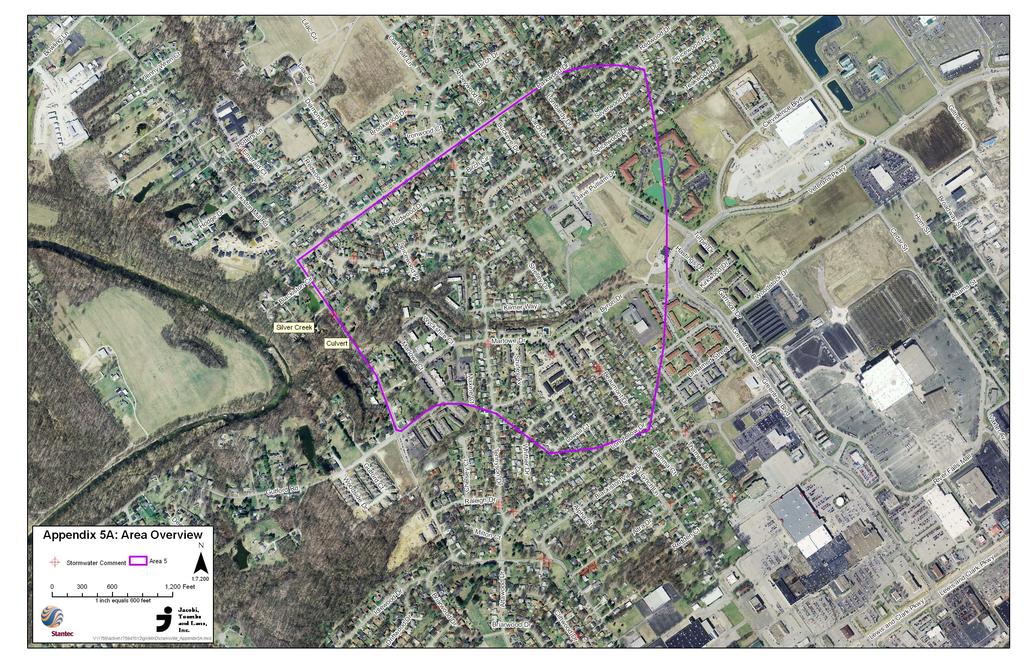
1 Area 5: Blackiston Mill Road at Dead Man's Hollow Flooding Assessment Jacobi, Toombs, and Lanz, Inc. This document summarizes an assessment of drainage and flooding concerns and provides recommendations for improving storm water management in Area 5 for the Town of Clarksville, Indiana. December 2008
2 AREA 5: BLACKISTON MILL ROAD AT DEADMAN S HOLLOW JTL Consulting Engineers Project Area Overview This report summarizes the project team s assessment and recommendations for Area 5, Blackiston Mill Road at Dead Man s Hollow, which has historically presented maintenance issues and flood hazards for the Town of Clarksville. The existing drainage conduit in this area suffered partial failure and has been slip-lined two times since its original construction. These activities have decreased the effective opening size from a 48-inch x 60-inch concrete box culvert (20.0 ft 2 cross-sectional area) to a 30-inch diameter PVC pipe (4.9 ft 2 cross-sectional area). During rainfall events of significant intensity, the existing 30-inch pipe under Blackiston Mill Road lacks the conveyance capacity to prevent backwater conditions upstream of the road embankment. At times, these high water surface elevations upstream of the structure have led to the overtopping of the roadway and presented public safety hazards and caused road closures. In addition, these conditions present significant challenges to the drainage and roadway maintenance activities of the Clarksville Street Department. The project team comprised of Stantec Consulting Services, Inc. (Stantec) and Jacobi, Toombs and Lanz, Inc. (JTL) conducted physical surveys and performed hydrologic and hydraulic assessments of the project area to determine the nature and extent of the problems and evaluate alternatives for improving drainage and reducing the risk of flooding at this location. Two solutions have been developed and are detailed in this report. These solutions include an in-kind replacement of the existing structure or a structure replacement with roadway improvements. The anticipated costs for improvements to this existing structure under Blackiston Mill Road are estimated to be 425,000. In addition, the anticipated cost for structure replacement and improvements to the roadway alignment is 685,000. E.1
3 AREA 5: BLACKISTON MILL ROAD AT DEADMAN S HOLLOW JTL Consulting Engineers Table of Contents PROJECT AREA OVERVIEW E INTRODUCTION BACKGROUND FLOODING PROBLEMS PROBLEM ASSESSMENT STUDY METHODOLOGY EXISTING CONDITIONS ANALYSIS PROPOSED SOLUTIONS ALTERNATIVE 1: BOX CULVERT ALTERNATIVE 2: BOX CULVERT WITH ROAD IMPROVEMENTS CONCLUSIONS i
4 AREA 5: BLACKISTON MILL ROAD AT DEADMAN S HOLLOW JTL Consulting Engineers 1.0 Introduction This report examines two conceptual alternatives to improve motorist safety and minimize maintenance requirements by reducing the flooding risk along Blackiston Mill Road at Dead Man s Hollow. The project team comprised of Stantec Consulting Services, Inc. (Stantec) and Jacobi, Toombs and Lanz, Inc. (JTL) conducted physical surveys and completed hydrologic and hydraulic assessments to identify the problems in the area and develop alternatives in the project area. Flooding problems in the area of Blackiston Mill Road at Dead Man s Hollow have increased in recent years because of the increased volume and intensity of stormwater runoff. This increased runoff is due to extensive developments in the watershed and degradation and partial failure of the existing structure under Blackiston Mill Road. 1.1 BACKGROUND The project area is located in the central and western portion of the Town of Clarksville, situated between the major intersections of Blackiston Mill Road with Gutford Road and Potters Lane. The existing outfall structure on Blackiston Mill Road is located approximately 600 feet east of Silver Creek. Silver Creek water surface elevations and backwater conditions were considered and incorporated into this design. The structure under Blackiston Mill Road is located in a steeply incised stream valley. The elevation difference from the centerline of the road to the invert of the current structure is approximately 24 feet. This project area is located in the Silver Creek Plum Run HUC14 watershed. According to the Natural Resources Conservation Service (NRCS), soils in this area are composed primarily of hydrologic soil group (HSG) C with some smaller areas containing HSG B. The majority of the area is composed of clayey stratum and silty loams which indicate poor soil infiltration capacity, which often leads to standing stormwater in poorly graded areas or regions with little drainage relief. Only very small regions contain soils which permit moderate infiltration abilities. The 451 acre watershed draining to this structure is composed primarily of residential properties in the lower subcatchments and heavy commercial properties located in the upper subcatchments. The watershed is relatively flat, ranging from 466 feet above sea level (FASL) to 474 FASL. The only area of significant elevation relief is immediately adjacent to the steeply incised ditch. Upstream of Blackiston Mill Road, the central open channel begins at the outlet of a 12-foot x 3-foot concrete box culvert that drains a heavy commercial area along Greentree Boulevard. The existing terrain creates a deep channel with steep slopes on both the upstream and downstream side of Blackiston Mill Road. The significant elevation difference between the channel bed and roadway surface results in a significant amount of storage upstream of the structure prior to flow overtopping the roadway. This causes high flow velocities through the culvert and scour downstream. 1.1
5 AREA 5: BLACKISTON MILL ROAD AT DEADMAN S HOLLOW JTL Consulting Engineers 2.0 Flooding Problems 2.1 PROBLEM ASSESSMENT The drainage structure at Dead Man s Hollow is believed to have originally been a 48-inch x 60- inch box culvert; however, due to structural deterioration, the existing structure was slip-lined with a 42-inch galvanized corrugated metal pipe. Due to further complications, the pipe was slip-lined again with a 30-inch, schedule 35 PVC pipe. These repairs have decreased the effective opening size from a 48-inch x 60-inch (20.0 ft 2 ) box culvert to a 30-inch PVC pipe (4.9 ft 2 ). During large rainfall events, the existing culvert cannot convey enough stormwater to prevent ponding along the upstream embankment of Blackiston Mill Road. Additionally, woody debris and trash accumulate at the structure opening and further reduce the flow capacity. This is a regular maintenance issue for the Clarksville Street Department. Additionally, this inadequate structure has regularly caused backups which overtop the roadway. When this overtopping occurs, it causes hazardous conditions for motorists, and requires immediate action by the Clarksville Street Department to close the roadway to traffic. During these events where overtopping occurs, erosion regularly takes place on the downstream side of the embankment. This also requires regular maintenance by the street department. High entrance and exit velocities occur at this structure due to the elevation of ponded water upstream of the structure. Erosion also occurs when stormwater overtops the roadway and flows down the steep embankment on the downstream side of the roadway. These two erosion problems require regular maintenance from the Clarksville Street Department. 3.0 Study Methodology Hydrologic (HEC-HMS) and hydraulic models (HEC-RAS) were developed to assess the drainage and flooding dynamics of Blackiston Mill Road at Dead Man s Hollow. Soil information from the Natural Resources Conservation Service (NRCS) and land use determined from aerial imagery were used to estimate runoff potential for the subwatersheds in the study area. Peak discharges for 24-hour storm events were estimated using the SCS method. Representative cross sections upstream and downstream of Blackiston Mill Road were surveyed by field crews, and used in the hydraulic model to compute peak water surface elevations. 3.2
6 AREA 5: BLACKISTON MILL ROAD AT DEADMAN S HOLLOW JTL Consulting Engineers 4.0 Existing Conditions Analysis A model representing the downstream portions of the watershed and Silver Creek was developed during this assessment. This model validated observations that the area downstream of Blackiston Mill Road is susceptible to backwater flooding from Silver Creek during a 100-year storm event. Consequently, the proposed improvements will only allow increased stormwater discharges underneath Blackiston Mill Road until the backwater conditions from the Silver Creek reach the same elevation as the proposed box culvert. Refer to Appendix 5A for a map of the watershed draining this area. 5.0 Proposed Solutions 5.1 ALTERNATIVE 1: BOX CULVERT Based upon the hydrologic and hydraulic (H & H) analysis, it was determined that an 8-foot x 10-foot box culvert would control the stormwater in a manner that would allow sufficient flow through the culvert while minimizing backwater conditions and controlling the rate of discharge to a sufficient degree to minimize the potential for downstream flooding. Refer to Appendix 5B for the HEC-HMS and Appendix 5C HEC-RAS results of this assessment. See Appendix 5D for the preliminary construction plan for this structure replacement. The estimated cost for the proposed 8 x10 box culvert is 425,000. A detailed breakdown of the engineer s estimate can be found in Appendix 5E. 5.2 ALTERNATIVE 2: BOX CULVERT WITH ROAD IMPROVEMENTS In addition to the proposed 8-foot x 10-foot box culvert recommended above, further improvements to the grade and alignment of Blackiston Mill Road could be implemented during the installation of the culvert to increase the height of the road and further minimize the potential for overtopping. This would further minimize road closures caused by backwater from Silver Creek. These modifications would also improve the traffic conditions and visibility through this portion of Blackiston Mill Road. The general layout and improved vertical roadway alignment can be found in Appendix 5D. The estimated cost of the proposed box culvert with additional road improvements is 685,000. An engineer s estimate of the proposed stormwater and roadway improvements can be found in Appendix 5F. 5.3
7 AREA 5: BLACKISTON MILL ROAD AT DEADMAN S HOLLOW JTL Consulting Engineers 6.0 Conclusions Blackiston Mill Road at Dead Man s Hollow has historically presented maintenance issues for the Clarksville Street Department and regular flood hazards for motorists. The existing drainage conduit in this area suffered partial failure and has been slip-lined two times since its original construction. These activities have decreased the effective opening of the structure to the point that its ability to sufficiently convey stormwater is no longer adequate, which results in high backwater developing. At times, these high water surface elevations upstream of the structure have led to the overtopping of the roadway and presented public safety hazards and caused road closures. The project team conducted physical surveys and developed hydrologic and hydraulic models to determine the nature and extent of the problems and evaluate alternatives for improving drainage and reducing the risk of flooding at this location. The anticipated costs for improvements to this existing structure under Blackiston Mill Road are estimated to be 425,000. In addition, the anticipated cost for structure replacement and improvements to the roadway alignment is 685,000. It is recommended that Alternative 2 is selected due to the increased roadway elevation. This increased elevation will not only further minimize flooding of Blackiston Mill at Deadman s Hollow, it will also serve to improve roadway geometry, reducing traffic safety hazards during both wet and dry weather. 6.4
8 Appendices
9 Appendix A
10
11 Appendix B
12 Simulation Run Area 5 Blackiston Mill - Existing Culvert Backwater Elevation Q Total (cfs) Min Ch El (ft) W.S. Elev (ft) Crit W.S. (ft) E.G. Elev (ft) Slope (ft/ft) Vel Chnl (ft/s) 24 Hour 1 Year Hour 2 Year Hour 5 Year Hour 10 Year Hour 25 Year Hour 50 Year Hour 100 Year Simulation Run Area 5 Blackiston Mill - Proposed Culvert Backwater Elevation Q Total (cfs) Min Ch El (ft) W.S. Elev (ft) Crit W.S. (ft) E.G. Elev (ft) Slope (ft/ft) Vel Chnl (ft/s) 24 Hour 1 Year Hour 2 Year Hour 5 Year Hour 10 Year Hour 25 Year Hour 50 Year Hour 100 Year
13 Culvert_Analysis Plan: Existing 4/3/2008 River Reach Legend WS 100 Year WS 50 Year WS 25 Year WS 10 Year WS 5 Year WS 2 Year WS 1 Year Ground 450 Elevation (ft) Main Channel Distance (ft)
14 Culvert_Analysis Plan: Proposed Culvert 4/3/2008 River Reach Legend WS 100 Year WS 50 Year WS 25 Year WS 10 Year WS 5 Year WS 2 Year WS 1 Year Ground 450 Elevation (ft) Main Channel Distance (ft)
15 Appendix C
16 Simulation Run Area 5 Blackiston Mill - Existing Conditions HEC-HMS Results Hydrologic Element Drainage Area (MI2) Peak Discharge (CFS) Time of Peak Volume (IN) 24 Hour 1 Year Subbasin Jan2008, 00: Hour 2 Year Subbasin Jan2008, 00: Hour 5 Year Subbasin Jan2008, 00: Hour 10 Year Subbasin Jan2008, 00: Hour 25 Year Subbasin Jan2008, 00: Hour 50 Year Subbasin Jan2008, 00: Hour 100 Year Subbasin Jan2008, 00:
17 Project: DeadMan Simulation Run: 24 Hour 1 Year Start of Run: 01Jan2008, 12:00 Basin Model: Basin 1 End of Run: 03Jan2008, 12:00 Meteorologic Model: 24Hr-1Yr Compute Time: 02Apr2008, 13:22:24 Control Specifications: Control 1 Volume Units: IN Hydrologic Element Drainage Area (MI2) Peak Discharge (CFS) Time of Peak Volume (IN) Subbasin Jan2008, 00:
18 Project: DeadMan Simulation Run: 24 Hour 2 Year Start of Run: 01Jan2008, 12:00 Basin Model: Basin 1 End of Run: 03Jan2008, 12:00 Meteorologic Model: 24Hr-2Yr Compute Time: 02Apr2008, 13:23:17 Control Specifications: Control 1 Volume Units: IN Hydrologic Element Drainage Area (MI2) Peak Discharge (CFS) Time of Peak Volume (IN) Subbasin Jan2008, 00:
19 Project: DeadMan Simulation Run: 24 Hour 5 Year Start of Run: 01Jan2008, 12:00 Basin Model: Basin 1 End of Run: 03Jan2008, 12:00 Meteorologic Model: 24Hr-5Yr Compute Time: 02Apr2008, 13:11:15 Control Specifications: Control 1 Volume Units: IN Hydrologic Element Drainage Area (MI2) Peak Discharge (CFS) Time of Peak Volume (IN) Subbasin Jan2008, 00:
20 Project: DeadMan Simulation Run: 24 Hour 10 Year Start of Run: 01Jan2008, 12:00 Basin Model: Basin 1 End of Run: 03Jan2008, 12:00 Meteorologic Model: 24Hr-10Yr Compute Time: 02Apr2008, 13:21:56 Control Specifications: Control 1 Volume Units: IN Hydrologic Element Drainage Area (MI2) Peak Discharge (CFS) Time of Peak Volume (IN) Subbasin Jan2008, 00:
21 Project: DeadMan Simulation Run: 24 Hour 25 Year Start of Run: 01Jan2008, 12:00 Basin Model: Basin 1 End of Run: 03Jan2008, 12:00 Meteorologic Model: 24Hr-25Yr Compute Time: 02Apr2008, 13:22:52 Control Specifications: Control 1 Volume Units: IN Hydrologic Element Drainage Area (MI2) Peak Discharge (CFS) Time of Peak Volume (IN) Subbasin Jan2008, 00:
22 Project: DeadMan Simulation Run: 24 Hour 50 Year Start of Run: 01Jan2008, 12:00 Basin Model: Basin 1 End of Run: 03Jan2008, 12:00 Meteorologic Model: 24Hr-50Yr Compute Time: 02Apr2008, 13:23:44 Control Specifications: Control 1 Volume Units: IN Hydrologic Element Drainage Area (MI2) Peak Discharge (CFS) Time of Peak Volume (IN) Subbasin Jan2008, 00:
23 Project: DeadMan Simulation Run: 24 Hour 100 Year Start of Run: 01Jan2008, 12:00 Basin Model: Basin 1 End of Run: 03Jan2008, 12:00 Meteorologic Model: 24Hr-100Yr Compute Time: 02Apr2008, 13:21:29 Control Specifications: Control 1 Volume Units: IN Hydrologic Element Drainage Area (MI2) Peak Discharge (CFS) Time of Peak Volume (IN) Subbasin Jan2008, 00:
24 Appendix D
25
26 Appendix E
27 Clarksville Stormwater Improvements BY HLH CHECKED JIL Area 5 Blackiston Mill Road Preliminary Cost Estimate - ALT #1 DATE 11/28/2008 JOB NO ITEM QUANTITY UNIT ENGINEER'S ESTIMATED UNIT COST EXTENSION Mobilization & Demobilization 1 LS 10, , Common Excavation 6800 CY , Borrow 8252 CY , HMA Surface, Type B 18 Ton , HMA Intermediate, Type B 36 Ton , HMA Base, Type B 53 Ton , Compacted Aggregate, No Ton , Clearing and Grubbing 1 LS 7, , Revetment Riprap 44 Ton , Seed and Straw Pavement Markings Guardrail, Remove Guardrail, W-beam 6'-3" spacing Traffic Maintenance Erosion Control Remove Existing Culvert SY LS LF LF LS LS LS , , , , , , , , , , , Construction Subtotal 334, % Contingency 33, % Engineering, Surveying, & Inspection 55, Total Estimated Construction Cost 422, USE 425,000
28 Appendix F
29 Clarksville Stormwater Improvements BY HLH CHECKED JIL Area 5 Blackiston Mill Road Preliminary Cost Estimate - ALT #2 DATE 11/28/2008 JOB NO ITEM QUANTITY UNIT ENGINEER'S ESTIMATED UNIT COST EXTENSION Mobilization & Demobilization 1 LS 10, , Common Excavation 6800 CY , Borrow CY , HMA Surface, Type B 106 Ton , HMA Intermediate, Type B 213 Ton , HMA Base, Type B 319 Ton , Compacted Aggregate, No Ton , Clearing and Grubbing 1 LS 10, , Demo Existing Road Surface 1660 SY , Modify Existing Lift Station 1 LS 10, , Revetment Riprap 44 Ton , Seed and Straw Pavement Markings Guardrail, Remove Guardrail, W-beam 6'-3" spacing Traffic Maintenance Erosion Control Remove Existing Culvert SY LS LF LF LS LS LS , , , , , , , , , , , Construction Subtotal 540, % Contingency 54, % Engineering, Surveying, & Inspection 89, Total Estimated Construction Cost 683, USE 685,000
30 Area 6: Adams Drive Drainage Assessment Jacobi, Toombs, and Lanz, Inc. This document summarizes an assessment of drainage and flooding concerns and provides recommendations for improving storm water management in Area 6 for the Town of Clarksville, Indiana. December 2008
INFLOW DESIGN FLOOD CONTROL SYSTEM PLAN 40 C.F.R. PART PLANT YATES ASH POND 3 (AP-3) GEORGIA POWER COMPANY
 GEORGIA POWER COMPANY") INFLOW DESIGN FLOOD CONTROL SYSTEM PLAN 40 C.F.R. PART 257.82 PLANT YATES ASH POND 3 (AP-3) GEORGIA POWER COMPANY EPA s Disposal of Coal Combustion Residuals from Electric Utilities Final Rule (40 C.F.R.
INFLOW DESIGN FLOOD CONTROL SYSTEM PLAN 40 C.F.R. PART 257.82 PLANT YATES ASH POND 3 (AP-3) GEORGIA POWER COMPANY EPA s Disposal of Coal Combustion Residuals from Electric Utilities Final Rule (40 C.F.R.
Standards for Soil Erosion and Sediment Control in New Jersey May 2012 STANDARD FOR SLOPE PROTECTION STRUCTURES. Definition
 STANDARD FOR SLOPE PROTECTION STRUCTURES Definition Structures to safely conduct surface runoff from the top of a slope to the bottom of the slope. Purpose The purpose of this practice is to convey storm
Old Mill School Stream Restoration
 Project Overview This conceptual plan restores and stabilizes two consecutive reaches of a highly incised and unstable stream and reconnects them with the floodplain. The restoration reaches are part of
INFLOW DESIGN FLOOD CONTROL SYSTEM PLAN 40 C.F.R. PART PLANT YATES ASH POND B (AP-B ) GEORGIA POWER COMPANY
 GEORGIA POWER COMPANY") INFLOW DESIGN FLOOD CONTROL SYSTEM PLAN 40 C.F.R. PART 257.82 PLANT YATES ASH POND B (AP-B ) GEORGIA POWER COMPANY EPA s Disposal of Coal Combustion Residuals from Electric Utilities Final Rule (40 C.F.R.
INFLOW DESIGN FLOOD CONTROL SYSTEM PLAN 40 C.F.R. PART 257.82 PLANT YATES ASH POND B (AP-B ) GEORGIA POWER COMPANY EPA s Disposal of Coal Combustion Residuals from Electric Utilities Final Rule (40 C.F.R.
INFLOW DESIGN FLOOD CONTROL SYSTEM PLAN PLANT BARRY ASH POND ALABAMA POWER COMPANY
 INFLOW DESIGN FLOOD CONTROL SYSTEM PLAN PLANT BARRY ASH POND ALABAMA POWER COMPANY Section 257.82 of EPA s regulations requires the owner or operator of an existing or new CCR surface impoundment or any
III. INVENTORY OF EXISTING FACILITIES
 III. INVENTORY OF EXISTING FACILITIES Within the Growth Management Boundary, the existing storm drainage facilities are largely associated with development that has historically occurred in the ten drainage
Highway Drainage 1- Storm Frequency and Runoff 1.1- Runoff Determination
 Highway Drainage Proper drainage is a very important consideration in design of a highway. Inadequate drainage facilities can lead to premature deterioration of the highway and the development of adverse
Lyon Creek Cedar Way Stormwater Detention Dam Operation and Maintenance Manual
 Lyon Creek Cedar Way Stormwater Detention Dam Operation and Maintenance Manual Prepared by: Mike Shaw Stormwater Program Manager City of Mountlake Terrace January 2010 Section I General Information This
Stormwater Local Design Manual For Houston County, Georgia
 Stormwater Local Design Manual For Houston County, Georgia Adopted November 15, 2005 TABLE OF CONTENTS 1. FORWARD... 1 2. GENERAL LEVEL OF SERVICE STANDARDS... 2 2.1. DETENTION REQUIREMENTS... 2 2.1.1.
E. STORMWATER MANAGEMENT
 E. STORMWATER MANAGEMENT 1. Existing Conditions The Project Site is located within the Lower Hudson Watershed. According to the New York State Department of Environmental Conservation (NYSDEC), Lower Hudson
Chapter 11 Culverts and Bridges
 Chapter 11 Culverts and Bridges Contents 1.0 Introduction... 1 2.0 General Design... 1 2.1 Design Criteria... 1 2.2 Design Flows... 1 2.3 Permitting and Regulations... 1 2.4 Aesthetics and Safety... 2
MODEL Stormwater Local Design Manual. City of Centerville
 MODEL Stormwater Local Design Manual City of Centerville Adopted December 6, 2005 TABLE OF CONTENTS 1. FORWARD... 1 2. GENERAL LEVEL OF SERVICE STANDARDS... 1 2.1. DETENTION REQUIREMENTS... 1 2.1.1. Discharge
SECTION 3 DRAINAGE. 3-1 General. 3-2 Drainage Ordinances and Legal Requirements
 SECTION 3 DRAINAGE 3-1 General All Drainage plans for proposed development shall be prepared by a Professional Engineer registered in Virginia, except as noted below. Further, their seal and signature
V. DRAINAGE IMPROVEMENTS
 V. DRAINAGE IMPROVEMENTS 5.1 Formulation of Drainage Improvements As indicated in Chapter 4, following the completion of the hydrologic analysis associated with future land use conditions, drainage improvements
INFLOW DESIGN FLOOD CONTROL SYSTEM PLAN 40 C.F.R. PART PLANT BOWEN ASH POND 1 (AP-1) GEORGIA POWER COMPANY
 GEORGIA POWER COMPANY") INFLOW DESIGN FLOOD CONTROL SYSTEM PLAN 40 C.F.R. PART 257.82 PLANT BOWEN ASH POND 1 (AP-1) GEORGIA POWER COMPANY EPA s Disposal of Coal Combustion Residuals from Electric Utilities Final Rule (40 C.F.R.
INFLOW DESIGN FLOOD CONTROL SYSTEM PLAN 40 C.F.R. PART 257.82 PLANT BOWEN ASH POND 1 (AP-1) GEORGIA POWER COMPANY EPA s Disposal of Coal Combustion Residuals from Electric Utilities Final Rule (40 C.F.R.
PART 3 - STANDARDS FOR SEWERAGE FACILITIES DESIGN OF STORM SEWERS
 PART 3 - STANDARDS FOR SEWERAGE FACILITIES 3.3 - DESIGN OF STORM SEWERS 3.301 Design of Storm Sewers A. General Information B. Investigations and Surveys C. Special Projects 3.302 Design Criteria for Storm
STORM WATER MANAGEMENT REPORT
 Silvercreek Junction STORM WATER MANAGEMENT REPORT Howitt Creek at the Silvercreek Parkway Site Guelph, Ontario August, 2008 TSH File 22304A-04 August 19, 2008 STORMWATER MANAGEMENT REPORT Howitt Creek
FINDINGS: Olsson used a three-step analysis strategy to develop a benefit cost ratio that would indicate the relative feasibility of this project.
 EXECUTIVE SUMMARY FINDINGS: Based on the results of this feasibility study, the Platte Republican Diversion Project would be cost-effective. With minimal improvements to the channel, and the existing bridge
Preliminary Drainage Analysis
 Preliminary Drainage Analysis Tanimura and Antle Employee Housing Town of Spreckels County of Monterey, California LIB150205 May 29, 2015 Prepared For: Tanimura and Antle Produce Prepared By: 9699 Blue
4.1 Browns Canal Introduction Sub-basin Information
 Section 4 Withlacoochee Basin 4.1 Browns Canal 4.1.1 Introduction The information presented in this sub-basin plan for Browns Canal is intended to provide the reader with information necessary to understand
APPENDIX G HYDRAULIC GRADE LINE
 Storm Drainage 13-G-1 APPENDIX G HYDRAULIC GRADE LINE 1.0 Introduction The hydraulic grade line is used to aid the designer in determining the acceptability of a proposed or evaluation of an existing storm
Temporary Watercourse Crossing: Culverts
 Temporary Watercourse Crossing: Culverts DRAINAGE CONTROL TECHNIQUE Low Gradient Velocity Control Short Term Steep Gradient Channel Lining Medium-Long Term Outlet Control Soil Treatment Permanent Symbol
Appendix G Preliminary Hydrology Study
 Appendix G Preliminary Hydrology Study Preliminary Hydrology Study VESTING TTM 72608 Long Beach, CA Prepared for: The Long Beach Project, LLC 888 San Clemente, Suite 100 New Port Beach, CA May 28, 2014
Chapter 8. Inlets. 8.0 Introduction. 8.1 General
 . Introduction This chapter provides criteria and design guides for evaluating and designing storm sewer inlets in the City of Centennial. The review of all planning submittals will be based on the criteria
10.0 Storm Sewer Systems
 October 2003 Chapter 10.0, Storm Sewer Systems Page 1 10.0 Storm Sewer Systems 10.1 Introduction A storm sewer system consists of a system of inlets, pipes, manholes, junctions, cleanouts, outlets, and
Appendix D - Evaluation of Interim Solutions
 Appendix D - Evaluation of Interim Solutions D.1 Introduction The implementation of long-term improvements is projected to take 5 to 8 years. To reduce the number of years of flooding impacts, the partner
DRAINAGE & DESIGN OF DRAINAGE SYSTEM
 Drainage on Highways DRAINAGE & DESIGN OF DRAINAGE SYSTEM P. R.D. Fernando Chartered Engineer B.Sc.(Hons), M.Eng. C.Eng., MIE(SL) Drainage Requirement of Highway Drainage System Introduction Drainage means
GRASS-LINED CHANNEL (acre) CODE 840
 CODE 840") NATURAL RESOURCES CONSERVATION SERVICE ILLINOIS URBAN MANUAL PRACTICE STANDARD GRASS-LINED CHANNEL (acre) CODE 840 (Source: NC Erosion and Sediment Control Field Manual) DEFINITION A natural or constructed
NATURAL RESOURCES CONSERVATION SERVICE ILLINOIS URBAN MANUAL PRACTICE STANDARD GRASS-LINED CHANNEL (acre) CODE 840 (Source: NC Erosion and Sediment Control Field Manual) DEFINITION A natural or constructed
Ponds. Pond A water impoundment made by excavating a pit, or constructing a dam or an embankment.
 POND SITE SELECTION AND CONSTRUCTION Uses, Planning, & Design David Krietemeyer Area Engineer USDA-NRCS June 20, 2008 Uses Considerations for Location of Commonly Used Terms Pond A water impoundment made
CITY UTILITIES DESIGN STANDARDS MANUAL
 CITY UTILITIES DESIGN STANDARDS MANUAL () September 2017 Page Chapter 1 Acronyms and Definitions 1.01 Purpose 1 1.02 Acronyms 1 1.03 Definitions 3 Chapter 2 Introduction 2.01 Purpose 1 2.02 Applicability
CHECKLIST FOR STREETS, INLETS, AND STORM SEWER DESIGN
 CHECKLIST FOR STREETS, INLETS, I. STREET CLASSIFICATION AND DESIGN CRITERIA A. Determine drainage classification for the roadway section using Table 7-1 or Table 7-2. B. Determine the allowable flow depth
APPENDIX C INLETS. The application and types of storm drainage inlets are presented in detail in this Appendix.
 Storm Drainage 13-C-1 APPENDIX C INLETS 1.0 Introduction The application and types of storm drainage inlets are presented in detail in this Appendix. 2.0 Inlet Locations Inlets are required at locations
Chapter 3 Dispersion BMPs
 Chapter 3 Dispersion BMPs 3.1 BMP L611 Concentrated Flow Dispersion 3.1.1 Purpose and Definition Dispersion of concentrated flows from driveways or other pavement through a vegetated pervious area attenuates
NEW CASTLE CONSERVATION DISTRICT. through. (Name of Municipality) PLAN REVIEW APPLICATION DRAINAGE, STORMWATER MANAGEMENT, EROSION & SEDIMENT CONTROL
 PLAN REVIEW APPLICATION DRAINAGE, STORMWATER MANAGEMENT, EROSION & SEDIMENT CONTROL") NEW CASTLE CONSERVATION DISTRICT through (Name of Municipality) PLAN REVIEW APPLICATION DRAINAGE, STORMWATER MANAGEMENT, EROSION & SEDIMENT CONTROL Office use only: Received by Municipality: Received by
NEW CASTLE CONSERVATION DISTRICT through (Name of Municipality) PLAN REVIEW APPLICATION DRAINAGE, STORMWATER MANAGEMENT, EROSION & SEDIMENT CONTROL Office use only: Received by Municipality: Received by
INFLOW DESIGN FLOOD CONTROL SYSTEM PLAN. Bremo Power Station CCR Surface Impoundment: North Ash Pond INFLOW DESIGN FLOOD
 INFLOW DESIGN FLOOD CONTROL SYSTEM PLAN INFLOW DESIGN FLOOD CONTROL SYSTEM PLAN Bremo Power Station CCR Surface Impoundment: North Ash Pond Submitted To: Bremo Power Station 1038 Bremo Bluff Road Bremo
COON CREEK WATERSHED DISTRICT PERMIT REVIEW. Spring Lake Park Schools Westwood Middle School st Avenue NE, Spring Lake Park, MN 55432
 PAN 16-112, Westwood Middle School, Page 1 of 6 COON CREEK WATERSHED DISTRICT PERMIT REVIEW MEETING DATE: August 22, 2016 AGENDA NUMBER: 10 FILE NUMBER: 16-112 ITEM: Westwood Middle School RECOMMENDATION:
ARTICLE V: STORMWATER MANAGEMENT AND DRAINAGE SYSTEMS
 ARTICLE V: STORMWATER MANAGEMENT AND DRAINAGE SYSTEMS Section 501: Purpose An adequate drainage system including necessary ditches, pipes, culverts, drains, inlets, bridges, detention ponds, etc. shall
Hydrologic Study Report for Single Lot Detention Basin Analysis
 Hydrologic Study Report for Single Lot Detention Basin Analysis Prepared for: City of Vista, California August 18, 2006 Tory R. Walker, R.C.E. 45005 President W.O. 116-01 01/23/2007 Table of Contents Page
Sediment Basin. Fe= (Depends on soil type)
") 3.9 Sediment Control Description: A sediment basin is an embankment with a controlled outlet that detains stormwater runoff, resulting in the settling of suspended sediment. The basin provides treatment
3.9 Sediment Control Description: A sediment basin is an embankment with a controlled outlet that detains stormwater runoff, resulting in the settling of suspended sediment. The basin provides treatment
Location Drainage Study
 Location Drainage Study PROJECT ROUTE: LIMITS: MUNICIPALITY/COUNTY: JOB NUMBER: IL 47 at Burlington Road 750ft NW to 750ft SE of IL 47(Burlington), & 1000ft S to 1000ft N of Burlington (IL47) Kane County
Chapter 7. Street Drainage. 7.0 Introduction. 7.1 Function of Streets in the Drainage System. 7.2 Street Classification
 7. Introduction This chapter summarizes methods to evaluate runoff conveyance in various street cross sections and curb types in the Town of Castle Rock and identifies acceptable upper limits of street
HYDROLOGIC-HYDRAULIC STUDY BAYAMON SOUTH COMMERCIAL CENTER BAYAMON, PUERTO RICO. Casiano Ancalle, P.E. August, 2006 I.
 HYDROLOGIC-HYDRAULIC STUDY BAYAMON SOUTH COMMERCIAL CENTER BAYAMON, PUERTO RICO Casiano Ancalle, P.E. August, 2006 I. INTRODUCTION A commercial development project named Bayamon South Commercial Center
Camp Creek: Tackling Erosion and Improving Water Quality in a Recreational Playground Mitchellville, Iowa
 Camp Creek: Tackling Erosion and Improving Water Quality in a Recreational Playground Mitchellville, Iowa Rachel Conrad, PE, CFM IAFSM March 10 th, 2016 Outline Project Background and Goals Modeling Results
PRELIMINARY DRAINAGE REPORT NEWCASTLE FIRE STATION OLD STATE HIGHWAY
 PRELIMINARY DRAINAGE REPORT FOR THE NEWCASTLE FIRE STATION OLD STATE HIGHWAY PREPARED FOR THE NEWCASTLE FIRE PROTECTION DISTRICT JULY 2014 BY ROSEVILLE DESIGN GROUP, INC. ROSEVILLE DESIGN GROUP, Inc Established
FIRM NAME DESIGNER: CHECKER: DATE: FPID #: DESCRIPTION: COUNTY: DRAINAGE DESIGN CHECKLIST. Designers Initials. Checkers Initials.
 I. Drainage Report A. Executive Summary - Brief Overview of Project Drainage Design B. Project Description 1. Existing Conditions 2. Proposed Project Conditions 3. Project Justification Narrative - Basin
Municipal Stormwater Ordinances Summary Table
 APPENDIX F Municipal Ordinances Summary Table Municipality Abington Bryn Athyn Borough Hatboro Borough Ordinance, SALDO Runoff equals pre post Erosion Sediment Control Water Quality Requirements Any which
BMP 6.4.4: Infiltration Trench
 BMP 6.4.4: Infiltration Trench An Infiltration Trench is a leaky pipe in a stone filled trench with a level bottom. An Infiltration Trench may be used as part of a larger storm sewer system, such as a
INFLOW DESIGN FLOOD CONTROL SYSTEM PLAN 40 C.F.R. PART PLANT DANIEL ASH POND B MISSISSIPPI POWER COMPANY
 INFLOW DESIGN FLOOD CONTROL SYSTEM PLAN 40 C.F.R. PART 257.82 PLANT DANIEL ASH POND B MISSISSIPPI POWER COMPANY EPA s Disposal of Coal Combustion Residuals from Electric Utilities Final Rule (40 C.F.R.
Chapter 4. Drainage Report and Construction Drawing Submittal Requirements
 4.0 Introduction The requirements presented in this section shall be used to aid the design engineer or applicant in the preparation of drainage reports, drainage studies, and construction drawings for
Chapter 6. Hydrology. 6.0 Introduction. 6.1 Design Rainfall
 6.0 Introduction This chapter summarizes methodology for determining rainfall and runoff information for the design of stormwater management facilities in the City. The methodology is based on the procedures
CHAPTER 12 BRIDGE DECK DRAINAGE SYSTEMS
 OFFICE OF STRUCTURES MANUAL FOR HYDROLOGIC AND HYDRAULIC DESIGN CHAPTER 12 BRIDGE DECK DRAINAGE SYSTEMS APRIL 2011 APRIL 2011 Page 1 Chapter Table of Contents 12.1 Policy... 12-3 12.1.1 Table 1... 12-3
MnDOT Flash Flood Vulnerability and Adaptation Assessment Pilot Project DISTRICT 1 SILVER CREEK CASE STUDY
 MnDOT Flash Flood Vulnerability and Adaptation Assessment Pilot Project DISTRICT 1 SILVER CREEK CASE STUDY NOVEMBER 2014 This document is part of a series of short reports based on the full Flash Flood
Cokato Lake (86-263) Wright County. Hydrologic Investigation
 Wright County. Hydrologic Investigation") Cokato Lake (86-263) Wright County Hydrologic Investigation April 14, 2005 Cokato Lake (86-263) Wright County Hydrologic Investigation April 14, 2005 Problem Statement In recent years, heavy rainfall has
Cokato Lake (86-263) Wright County Hydrologic Investigation April 14, 2005 Cokato Lake (86-263) Wright County Hydrologic Investigation April 14, 2005 Problem Statement In recent years, heavy rainfall has
CITY OF TROY DESIGN STANDARDS AND CONSTRUCTION SPECIFICATIONS
 CITY OF TROY DESIGN STANDARDS AND CONSTRUCTION SPECIFICATIONS PREPARED BY: F-7587 JANUARY 2010 TABLE OF CONTENTS SECTION 1 SECTION 2 SECTION 3 SECTION 4 SECTION 5 SECTION 6 APPENDIX ROADWAY DESIGN DRAINAGE
Project Drainage Report
 Design Manual Chapter 2 - Stormwater 2A - General Information 2A-4 Project Drainage Report A. Purpose The purpose of the project drainage report is to identify and propose specific solutions to stormwater
Hydrologic Calibration:
 Hydrologic Calibration: UPDATE OF EFFECTIVE HYDROLOGY FOR MARYS CREEK October 2010 Agenda Background Hydrologic model Calibrated rainfall Hydrologic calibration 100 year discharges, Existing Conditions
DRAFT. Jacob Torres, P.E.; Nick Fang, Ph.D., P.E.
 \ Memorandum SSPEED Center at Rice University Department of Civil & Environmental Engineering 6100 Main MS-317 Houston, Texas 77005-1827 sspeed.rice.edu tel: 713-348-4977 To Andy Yung, P.E. CFM; Lane Lease,
City of Saint John. Storm Drainage Design Criteria Manual
 Storm Drainage Design Criteria Manual March 7, 2016 LIST OF 2016 REVISIONS PAGES SECTION TITLE iii, iv, v, vi All Table of Contents 31-35 3 SUBMISSION REQUIREMENTS March 7, 2016 Page i DISCLAIMER The material
Master Plan of Storm Drainage for East Garden Grove Wintersburg Channel Tributary Area
 CITY OF ANAHEIM Master Plan of Storm Drainage for East Garden Grove Wintersburg Channel Tributary Area JANUARY 2006 VOLUME 1 Table of Contents VOLUME 1 1. Executive Summary... 1 1.1 General... 1 1.2
Hydrology Study. Ascension Heights Subdivision Ascension Drive at Bel Aire Road San Mateo, California (Unincorporated)
") Hydrology Study Ascension Heights Subdivision Ascension Drive at Bel Aire Road San Mateo, California (Unincorporated) Prepared for San Mateo Real Estate & Construction March 9, 21 Rev. 1 11-8-211 Rev.
Hydrology Study Ascension Heights Subdivision Ascension Drive at Bel Aire Road San Mateo, California (Unincorporated) Prepared for San Mateo Real Estate & Construction March 9, 21 Rev. 1 11-8-211 Rev.
December 7, Dr. Christine Pomeroy University of Utah Civil and Environmental Engineering MCE Salt Lake City, UT. Dear Dr.
 December 7, 2012 Dr. Christine Pomeroy University of Utah Civil and Environmental Engineering MCE 2042 Salt Lake City, UT 84112 Dear Dr. Pomeroy, The following document is the final report of the Red Butte
Stantec Consulting Services Inc Lebanon Road, Cincinnati, OH 45241
 Stantec Consulting Services Inc. 11687 Lebanon Road, Cincinnati, OH 45241 File: 175534017 Revision 0 Ohio Valley Electric Corporation 3932 U.S. Route 23 P.O. Box 468 Piketon, Ohio 45661 RE: Run-on and
SECTION STORM DRAINAGE DESIGN, GRADING, AND WATER QUALITY TECHNICAL CRITERIA TABLE OF CONTENTS PAGE 402 STORM DRAINAGE DESIGN CRITERIA 400-1
 CITY OF THORNTON Standards and Specifications Revised: October 2012 SECTION 400 - STORM DRAINAGE DESIGN, GRADING, AND WATER QUALITY TECHNICAL CRITERIA TABLE OF CONTENTS PAGE 401 GENERAL PROVISIONS 400-1
Considerations In Estimating Tailwater Elevations
 Considerations In Estimating Tailwater Elevations by Alphonse (Al) J. Stewart, P.E., President www.suncam.com Page 1 of 39 ************************************************************************ This
HYDROLOGIC-HYDRAULIC STUDY ISABELLA OCEAN RESIDENCES ISLA VERDE, CAROLINA, PR
 HYDROLOGIC-HYDRAULIC STUDY ISABELLA OCEAN RESIDENCES ISLA VERDE, CAROLINA, PR 1 INTRODUCTION 1.1 Project Description and Location Isabella Ocean Residences is a residential development to be constructed
Diversion Dikes. Fe=0.95
 2.2 Diversion Dike Erosion Control Description: A diversion dike is a compacted soil mound, which redirects runoff to a desired location. The dike is typically stabilized with natural grass for low velocities
STORM AND SURFACE WATER 4-1 GENERAL...4-1
 SECTION 4 STORM AND SURFACE WATER SECTION DESCRIPTION PAGE 4-1 GENERAL...4-1 4-2 STORM DRAINAGE CONVEYANCE SYSTEM DESIGN CRITERIA...4-1 4-2.1 Overview...4-1 4-2.2 Design Flow and Route Requirements...4-2
City of Katy Flood Protection Study (Meeting 3 of 3) October 23, 2017
 October 23, 2017") City of Katy Flood Protection Study (Meeting 3 of 3) October 23, 2017 Phasing of Meetings April Meeting May Meeting October Review of Tax Day Storm Event and Immediate Actions Taken By City Review of Coordination
City of Katy Flood Protection Study (Meeting 3 of 3) October 23, 2017 Phasing of Meetings April Meeting May Meeting October Review of Tax Day Storm Event and Immediate Actions Taken By City Review of Coordination
Gwinnett County Stormwater System Assessment Program
 Gwinnett County Stormwater System Assessment Program Jonathan Semerjian, PE Dept. of Water Resources Stormwater Management Sam Fleming, PE Dewberry Presentation Overview Project Background Drivers Enhanced
Stormwater Management Studies PDS Engineering Services Division ES Policy # 3-01
 Stormwater Management Studies PDS Engineering Services Division Revised Date: 2/28/08 INTRODUCTION The City of Overland Park requires submission of a stormwater management study as part of the development
Volume 2, Chapter 10 - Storage
 Volume 2, Chapter 10 - Storage Users Guidance: If a UDFCD Section number in this chapter is skipped: It was adopted as is; please refer to that Section in the corresponding UDFCD Manual, Volume, Chapter
CCR Certification: Initial Inflow Design Flood Control System Plan for the
 Submitted to Southern Indiana Gas & Electric Company dba Vectren Power Supply, Inc. (SIGECO) One Vectren Square Evansville, IN 4778 Submitted by AECOM 94 Amberglen Boulevard Austin, Texas 78729 October
HYDROLOGY REPORT HEACOCK & CACTUS CHANNELS MORENO VALLEY, CALIFORNIA NOVEMBER 2005 REVISED APRIL 2006 REVISED AUGUST 2006
 HYDROLOGY REPORT HEACOCK & CACTUS CHANNELS MORENO VALLEY, CALIFORNIA NOVEMBER 2005 REVISED APRIL 2006 REVISED AUGUST 2006 RIVERSIDE COUNTY FLOOD CONTROL AND WATER CONSERVATION DISTRICT TABLE OF CONTENTS
Supplemental Watershed Plan Agreement No. 10 for Neshaminy Creek Watershed Core Creek Dam (PA-620) Bucks County, Pennsylvania
 Bucks County, Pennsylvania") Supplemental Watershed Plan Agreement No. 10 for Neshaminy Creek Watershed Core Creek Dam (PA-620) Bucks County, Pennsylvania Project Authorization USDA's Small Watershed Program is carried out under the
Supplemental Watershed Plan Agreement No. 10 for Neshaminy Creek Watershed Core Creek Dam (PA-620) Bucks County, Pennsylvania Project Authorization USDA's Small Watershed Program is carried out under the
Inflow Design Flood Control System Plan
 Inflow Design Flood Control System Plan For Compliance with the Coal Combustion Residuals Rule (40 CFR Part 257) Cherokee Station - CCR Surface Impoundments Public Service Company of Colorado Denver, Colorado
ROLES AND RESPONSIBILITIES Small Pond Approval. SWM MD-378 Pond Checklist Training 10/17/07. Exemptions EMBANKMENT HEIGHT. Height of Dam Weir Wall
 SWM MD-378 Pond Checklist Training 10/17/07 Ken Wolfe Warren Johnson USDA, NRCS Frederick, Maryland ROLES AND RESPONSIBILITIES Small Pond Approval MDE, WMA, Dam Safety Division Authority (COMAR 26.17.04.03)
New Castle County, DE. Floodplain Regulations
 New Castle County, DE Floodplain Regulations John J. Gysling, PE CFM Department of Land Use New Castle County, DE February 26, 2009 Today s Presentation Floodplain Protection and Uses Terms and Definitions
SECTION 2 DESIGN CRITERIA
 SECTION 2 DESIGN CRITERIA 2.1 GENERAL The following criteria will be utilized by the District Engineer, and/or a consultant, in the review of development plans for recommending approval of the proposed
FLAGSTAFF FAMILY FOOD BANK FLOOD REMEDIATION PROJECT
 FLAGSTAFF FAMILY FOOD BANK FLOOD REMEDIATION PROJECT Final Design Report 5/12/2016 Erik Henricksen, Elena Smith, Garrett Ribas, Meshal Alotaibi Table of Contents Acknowledgments... 3 1.0 Project Description...
The City of North Las Vegas (CNLV) does not allow valley gutters to be constructed across streets with right-of-way widths of 80 feet or greater.
 does not allow valley gutters to be constructed across streets with right-of-way widths of 80 feet or greater.") Background The City of rth Las Vegas strives to provide the development community with adequate information to ensure the successful completion of any project in the City. To aid in the submittal of a
Background The City of rth Las Vegas strives to provide the development community with adequate information to ensure the successful completion of any project in the City. To aid in the submittal of a
TEMPORARY SEDIMENT TRAP CODE
 ILLINOIS URBAN MANUAL PRACTICE STANDARD TEMPORARY SEDIMENT TRAP CODE 960 Source: DEFINITION A small temporary stormwater storage structure designed to trap sediment. PURPOSE The purpose of this practice
4.8. Subsurface Infiltration
 4.8. Subsurface Infiltration Subsurface infiltration systems are designed to provide temporary below grade storage infiltration of stormwater as it infiltrates into the ground. Dry wells, infiltration
Pre-Treatment Bioretention Cells Bioswales IOWA STORMWATER MANAGEMENT MANUAL DECEMBER 16, 2015
 Pre-Treatment Bioretention Cells Bioswales IOWA STORMWATER MANAGEMENT MANUAL DECEMBER 16, 2015 Urban Runoff Background How we got here What Problem?? Provenance of the Problem Unified Sizing Criteria What
Summary of Detention Pond Calculation Canyon Estates American Canyon, California
 July 15, 2015 Bellecci & Associates, Inc Summary of Detention Pond Calculation Canyon Estates American Canyon, California 1. Methodology: Method: Unit Hydrograph Software: Bentley Pond Pack Version 8i
City Plaza Residential (TPM ) Preliminary Hydrology Report
 Preliminary Hydrology Report") Hydrology Study City Plaza Residential (TPM 2016-127) Preliminary Hydrology Report Orange, Orange County, California Prepared For: Greenlaw Partners 18301 Von Karman Avenue, Suite 250 Irvine, CA 92612
Hydrology Study City Plaza Residential (TPM 2016-127) Preliminary Hydrology Report Orange, Orange County, California Prepared For: Greenlaw Partners 18301 Von Karman Avenue, Suite 250 Irvine, CA 92612
Overview of NRCS (SCS) TR-20 By Dr. R.M. Ragan
 TR-20 By Dr. R.M. Ragan") Overview of NRCS (SCS) TR-20 By Dr. R.M. Ragan TR-20 is a computer program for the simulation of runoff occurring from a single storm event. The program develops flood hydrographs from runoff and routes
Overview of NRCS (SCS) TR-20 By Dr. R.M. Ragan TR-20 is a computer program for the simulation of runoff occurring from a single storm event. The program develops flood hydrographs from runoff and routes
Inflow Design Flood Control System Plan
 Inflow Design Flood Control System Plan For Compliance with the Coal Combustion Residuals Rule (40 CFR Part 257) Valmont Station - CCR Surface Impoundments Public Service Company of Colorado Denver, Colorado
Watershed size and name: The drainage area is acres. The pond is located within the Ohio River watershed. (2016 Inflow Design Plan)
") A. B. Brown History of Construction 40 CFR 257.73 (c) (i.) (ii.) (iii.) Owner Name: Southern Indiana Gas and Electric Company dba Vectren Power Supply Owner Address: One Vectren Square, PO Box 209, Evansville,
A. B. Brown History of Construction 40 CFR 257.73 (c) (i.) (ii.) (iii.) Owner Name: Southern Indiana Gas and Electric Company dba Vectren Power Supply Owner Address: One Vectren Square, PO Box 209, Evansville,
Article 20: Erosion Control and Stormwater Management
 Article 20: Erosion Control and Stormwater Management Section 360: Purpose, Scope of Authority, Performance Guarantee and Approvals A. Purpose. The purpose of this document is to set forth minimum requirements
Standards for Soil Erosion and Sediment Control in New Jersey May 2012 STANDARD FOR GRASSED WATERWAYS. Definition. Purpose
 STANDARD FOR GRASSED WATERWAYS Definition A natural or constructed watercourse shaped or graded in earth materials and stabilized with suitable vegetation for the safe conveyance of runoff water. Purpose
HYDROLOGY STUDY LA MIRADA BOULEVARD La Mirada, California
 HYDROLOGY STUDY 12000 LA MIRADA BOULEVARD La Mirada, California TTM 73119 Prepared for: The Olson Company 3010 Old Ranch Parkway, Suite 100 Seal Beach, CA 90740 Contact: Mr. Aaron Orenstein (562) 370-9531
Storm Drain Inlet Protection
 Categories EC Erosion Control SE Sediment Control TC Tracking Control WE Wind Erosion Control Non-Stormwater NS Management Control Waste Management and WM Materials Pollution Control Legend: Primary Category
STORM DRAINAGE DESIGN CRITERIA
 BWM Orig. 01/01/05 Revised 01/01/10 LUCAS COUNTY ENGINEERS OFFICE STORM DRAINAGE DESIGN CRITERIA Drainage The design of storm sewer systems will be based upon the Rational Method using the equation Q=CiA
Appendix J Hydrology and Hydraulics
 Appendix J Hydrology and Hydraulics Marsh Lake Dam Ecosystems Restoration Feasibility Study Hydraulics & Hydrology Appendix January 2011 Contents List of Figures iii List of Tables iii I. General 1 II.
North Umpqua Hydroelectric Project (FERC 1927) Erosion Control Plan Site Remediation/ Assessment Form
 Erosion Control Plan Site Remediation/ Assessment Form") (FERC 1927) Erosion Control Plan Site Remediation/ Assessment Form Site # CW2-3 Priority Ranking Med Locator Information/GPS Lat: Long: Impact Rating 3 Start Project Development: Clearwater 2 Risk Rating
(FERC 1927) Erosion Control Plan Site Remediation/ Assessment Form Site # CW2-3 Priority Ranking Med Locator Information/GPS Lat: Long: Impact Rating 3 Start Project Development: Clearwater 2 Risk Rating
Erosion & Sedimentation Control Policy
 Issue Date 10/22/2010 Page 1 of 8 Erosion & Sedimentation Control Policy Introduction: Soil erosion is the removal of soil by water, wind, ice or gravity and sediment deposition occurs when the rate of
Applying landforming to reclamation: A case study in Central Appalachia
 Applying landforming to reclamation: A case study in Central Appalachia Leslie Hopkinson, John Quaranta April 12, 2017 Department of Civil and Environmental Engineering West Virginia University WEST VIRGINIA
VALLEY MEADOWS PARK IMPROVEMENTS REPORT
 VALLEY MEADOWS PARK IMPROVEMENTS REPORT for The Borough of Carlisle CUMBERLAND COUNTY, PENNSYLVANIA Prepared by: FREDERICK, SEIBERT & ASSOCIATES, INC. www.fsa-md.com CIVIL ENGINEERS SURVEYORS LANDSCAPE
SUBSURFACE INFILTRATION SYSTEM DESCRIPTION. Alternative Names: Sump, Drywell, Infiltration Trench, Infiltration Galleries, Leach Fields
 4.1-d SUBSURFACE INFILTRATION SYSTEM Alternative Names: Sump, Drywell, Infiltration Trench, Infiltration Galleries, Leach Fields BMP DESIGN APPROACH Pollutant Source Control Hydrologic Source Control Stormwater
Appendix J: Storm Conveyance Design Parameters
 Appendix J: Storm Conveyance Design Parameters Drain Commissioner 39 February 2005 STORM DRAINAGE DESIGN CRITERIA A. STORM SEWERS 1. The required discharge capacity shall be determined by the Rational