Technical Guide DELTA -VENT SA
|
|
|
- Gladys Atkins
- 6 years ago
- Views:
Transcription


1 DELTA protects property. Saves energy. Creates comfort. Technical Guide DELTA -VENT SA Air Barrier Systems for Low- and Mid-rise Commercial and Residential Buildings January 2015 Edition
2 Cosella-Dörken Leading Through Technical Competence Cosella-Dörken Products, Inc. is a subsidiary of the Dörken Group that has over 100 years of experience in the construction industry. Developed from innovative ideas and manufactured on state-of-the-art production lines, the premium quality products for moisture management in building enclosures set standards for reliability, durability, and energy savings. Located in Beamsville, Ontario, Canada, Cosella-Dörken provides customized solutions and products of outstanding quality. Cosella-Dörken Products, Inc. is and always will be a trustworthy and highly respected partner for designers, architects, distributors and installers. Contents Introduction 3 What you will find in this guide 3 The Building Enclosure and Air Barrier Systems 5 A functional overview of the building enclosure 5 The Perfect Wall 6 Rain Penetration Control 6 Recommendations for rain penetration control 7 Window Installation 8 Air Control 9 The Air Barrier System (ABS) 9 Basic requirements for Air Barrier Systems 10 Recommendations for air control in all climate zones 11 Thermal Control 12 Thermal bridging 12 Condensation control 13 Recommendations for thermal control by climate zone 14 Vapor Control 16 Inward vapor drive 16 Where and when to use DELTA -VENT SA 16 Recommendations for interior vapor control by climate zone 18 Material Properties 20 DELTA -VENT SA and LEED Building Design and Construction 22 Installation Details 27 References and Resources 62 DELTA -iselect 63 DISCLAIMER: Substantial effort has been made to ensure that all data and information in this publication is accurate. Cosella-Dörken and Building Science Consulting Inc. cannot accept responsibility of any errors or oversights in the use of material or in the preparation of architectural or engineering plans. The design professional must recognize that no design guide can substitute for experienced engineering and professional judgment. This publication is intended for use by professional personnel competent to evaluate the significance and limitations of its contents and able to accept responsibility for the application of the material it contains. Users are encouraged to offer comments to Cosella-Dörken and to Building Science Consulting Inc. on the content and suggestions for improvement. Questions concerning the source and derivation of any material in the design guide should be directed to Cosella- Dörken and Building Science Consulting Inc. Prepared by: John Straube, Ph.D., P.Eng. (Primary Author) Alex Lukachko, M.Arch. Marcus Jablonka, Dipl. Ing., Dipl. Wirt. Ing. Peter Barrett, B.A. (Hons), M.B.A. Krzysztof Apriasz, C.Tech. 2

3 Introduction What you will find in this guide This Technical Guide covers the design and construction of complete air barrier systems using DELTA -VENT SA for low- and mid-rise commercial and residential buildings in continental North America. DELTA -VENT SA is a self-adhered water-resistive membrane and air barrier component. DELTA -VENT SA exceeds the most stringent requirements of the Air Barrier Association of America (ABAA D ), the National Air Barrier Association (NABA), and the National Building Code of Canada (NBC 2010) based on the results of ASTM E Standard Test Method for Determining Air Leakage of Air Barrier Assemblies. An air barrier system (air control layer) to control the flow of air is required in all building enclosure components that separate two different environments. All modern buildings in all climates require air barriers. They are a critical component for high performance enclosures. In many building types, the air barrier system also separates the conditioned air from different environmental zones within the building. Air barrier systems also define the location of the pressure boundary of the building enclosure. In multi-occupancy construction, the air barrier system is also almost always part of the fire barrier and smoke barrier and sound control of the inter-unit separations. In such assemblies, the air barrier system must also meet the specific fire resistance and sound resistance rating requirement for the given separation. An air barrier system is provided to control airflow across the enclosure. Airflow should be controlled for a number of reasons, including the following: 1. to ensure good indoor air quality (accidental paths of airflow rarely provide sufficient quality or quantity of air to guarantee indoor air quality, and flow paths through enclosure elements often contain pollutants such as mold spores, off-gassing, etc.), 2. to reduce inward airflow and its attendant comfort problems due to cold drafts, and increased humidity problems in hothumid climates, 3. to avoid condensation of water vapor as warm humid air flowing from the inside (in cold weather) or outside (in hot weather) contacts cold surfaces within the enclosure, 4. to reduce heat loss/gain, of which air leakage is an important component, particularly in well-insulated buildings, and 5. to reduce sound and odor transmission, which is typically dominated by small penetrations through the enclosure. This guide describes the use of DELTA -VENT SA and other DELTA products to meet these needs for high performance low- and midrise commercial and residential buildings. 3


4 In this Technical Guide, you will find a building science primer with recommendations by climate zone and a series of best practice enclosure detail drawings for low- and midrise commercial and residential buildings. Residential Application Risinger Homes, Austin, TX Commercial Application Whole Foods, Cherry Hill, NJ 4


5 The Building Enclosure and Air Barrier Systems A functional overview of the building enclosure The building enclosure is defined as the physical component of a building that separates the interior environment from the exterior environment: it is an environmental separator. In general, the physical function of environmental separation can be further grouped into three sub-categories: 1. Support, i.e., to support, resist, transfer and otherwise accommodate all structural loading imposed by the interior and exterior environments, by the enclosure, and by the building itself. Sometimes, the enclosure, or portions of it, can be an integral part of the building superstructure either by design or in actual performance. 2. Control, i.e., to control, block, regulate and/or moderate all the loadings due to the separation of the interior and exterior environments. This means the flow of mass (rain, air, water vapor, pollutants, etc.) and energy (heat, sound, fire, light, etc.). 3. Finish, i.e., to finish the surfaces at the interface of the enclosure with the interior and exterior environments. Each of the two interfaces must meet the relevant visual, aesthetic, durability and other performance requirements. For physical performance, the required enclosure control functions include resistance to: rain penetration, air flow, heat transfer, condensation, fire and smoke propagation, sound and light transmission (including view, solar heat, and daylight), insect infestation and particulate penetration, and human access. Because these functions are required everywhere, continuity of these control functions, especially at penetrations, connections and interfaces between materials, is critical to a high performance enclosure. The most important control function with respect to durability is rain control, followed by air control, thermal control, and vapor control. The level of fire and sound control required varies with code and owner requirements. This guide provides recommendations for commercial and residential wall construction encompassing rain control, air control, thermal control, and vapor control requirements. Air barrier continuity at penetrations 5
6 The Building Enclosure and Air Barrier Systems The Perfect Wall The support/control/finish components of a typical enclosure assembly are presented in a conceptually perfect sequence in Figure 1. water control layers, all of which are to the exterior of the building structure and interior finishes. Such a strategy works well in all climate zones, from Northern heating-dominated climates to hot and humid Southern climates. The concept diagram shows a drained and ventilated exterior finish layer (the cladding ) outside of the thermal, air, vapor, and Exterior Finish Water control layer Air control layer Thermal control layer Vapor control layer Structure Service Interior finish Figure 1: Diagram of the Perfect Wall showing ideal sequence of assembly layers (From John Straube, High Performance Enclosures, Building Science Press) By locating the thermal (heat flow) control layer (insulation) on the exterior of the structure and by locating the combined air, water, and vapor control layers between the structure and the insulation, the structure and control layers are protected from UV exposure, impact, and temperature extremes, thereby increasing the durability of the critical control layers. The idea of the perfect wall is intended to guide designers on the proper principles during concept design. The same approach can be extended to other enclosure elements such as roofs and foundations. It should be used to ensure continuity of the enclosure control layers when designing details describing the connection between enclosure components like control joints, window and mechanical penetrations. The details provided in this guide use this approach. DELTA -VENT SA is intended to be used as the primary water and air control layer in walls systems. Rain Penetration Control There are three recognized design stra tegies to control rain penetration within and through the enclosure: Storage, Drained Screen, or Perfect Barriers. In a Storage (or Mass) approach, it is assumed that water penetrates the outer surface of the wall and then is stored within the mass of the enclosure, eventually removed by drying to the inside or outside. The maximum quantity of rain that can be controlled is limited by the storage capacity available relative to drying conditions. Some examples of mass systems include adobe walls, thatched roofs, solid multi-wythe brick masonry, and singlewythe block masonry that is still employed for some modern buildings. Drained enclosures assume some rainwater will penetrate the outer surface (hence the cladding screens the rain) and therefore the assembly must be designed to remove this water by providing drainage (comprised of a capillary breaking drainage plane such as DELTA -VENT SA, a drainage gap, flashing, and weep hole/drain). Many cladding systems, such as brick veneer and stucco, leak, as do the joints between other cladding types, such as shakes, terra-cotta, small metal panels, or natural stone. For these cladding types, drainage is a practical and successful approach for rain penetration control. Ventilated rainscreen systems like DELTA -DRY are designed to provide for drainage and drying in wall assemblies that use these claddings. Perfect Barrier systems stop all water penetration at a single plane. Such perfect control required the advent of modern materials. Because it is difficult to build and maintain a perfect barrier with many materials, it is common to recommend the use of drained walls. However, some systems, usually factory built, provide wall elements that are practical perfect barriers. For example, architectural precast concrete can be considered watertight, as can glazing, and roof membranes. The joints between perfect barrier elements almost always should be drained joints in the form of two-stage sealant joints or similar. 6

7 Recommendations for rain penetration control The significance of rainwater management cannot be over-emphasized. Along with the structural support function, it is usually this functional requirement that defines an enclosure design approach. the world experience a significant amount of wind-driven rain, and those areas exposed to hurricanes can have extreme exposure conditions. While this type of climate demands good rain control strategies for enclosure walls, the rain deposited on walls can be significantly reduced by good design and siting. The climate and site play a large role in defining the amount of rain to which a building is exposed. The amount of annual rainfall is one factor in gauging the rain exposure for a wall assembly (see Figure 2). This is modified by other factors, including the coincidence of rainfall with wind events, the orientation of the building, and height of the building. Most parts of Figure 2: Annual Rainfall Map (From John Straube, High Performance Enclosures, Building Science Press. Based on information from the U.S. Department of Agriculture and Environment Canada) Drained screen wall recommendations Screened wall systems are inherently more forgiving than either mass or perfect barrier systems. Properly designed and built screened wall systems will provide economical and durable rain penetration control. Failures in screened systems tend to occur because drainage was not provided (either through a design or construction failure). The most reliable and widely applicable approach is to follow the mantra: Deflection, Drainage/Exclusion/ Storage, and Drying Proper siting of the building and the use of sloped hip roofs and generous overhangs deflect driving rain, even for tall buildings. Water on the surface of the wall is shed from and deflected around openings by surface features, drip edges, and protruding flashing. Water is removed from the base of the wall by sloping the grade, and siding is kept at least 8 (200 mm) above grade to protect it from splashes. Rainwater will penetrate the cladding at joints, laps and penetrations. This water should be removed by drainage on a drainage plane, such as DELTA -VENT SA, and through a drainage space and redirected to the exterior by the use of waterproof flashing with lap joints sealed and overlapped in shingle fashion. DELTA -VENT SA has a unique feature that makes a simple overlap reliably water- and air-tight. Each membrane sheet has an adhesive strip with a release liner on the exterior side of the top edge. When the sheet above is lapped over and adhered, this makes an adhesive-to-adhesive sealed lap, reducing the possibility of peeling and leakage at material laps. Water that remains within the drainage cavity will be absorbed into the cladding and may even penetrate into the structural sheathing or stud space. This water should be removed by drying to the exterior and/ or the interior by allowing diffusion drying and ventilating the space behind the cladding. Even for adhered cladding systems (such as stucco or manufactured stone veneer) and directly attached claddings (such as wood or fiber cement) a space for drainage and drying can be created with the DELTA -DRY structured membrane. Pressure equalized screened systems offer only marginal benefits in most situations. So long as drainage and capillary breaks are provided, the reduced water penetration that may (and in many cases may not) result from pressure equalization does not aid rain control failure will still be by a failure to drain. 7


8 The Building Enclosure and Air Barrier Systems Window Installation Perhaps the most common rainwater control failure occurs at window penetrations. Regardless of which rain penetration control strategy is used, window and door penetrations through a cavity wall should be drained. Sub-sill flashings (see Figure 3) of various types are widely available for this purpose. For drained systems, the flashing can drain into the drainage gap. Figure 3 shows sub-sill flashings for punched window openings in an opaque wall section. Larger openings, such as curtainwall, window wall, or storefront glazing systems should be treated in a similar way. Many unitized window systems come with drainage tracks or pans that are integrated into the window system. It should be noted that the purpose of these components is to drain the window unit not necessarily the window opening and rainwater penetration often occurs at the interface between the window frame system and the opening in the adjacent enclosure. Figure 4 shows DELTA -FAS CORNER components, which when used as part of the DELTA -VENT SA system, protect all four corners of the window rough opening. Self-adhered membrane Formable self-adhered membrane Liquid applied membrane Pre-formed flashing system Figure 3: Sub-sill flashing below all window and door openings is a critical component to ensure resistance to rain penetration. DELTA -FAS CORNER at corners of rough opening DELTA -VENT SA install on field of wall, cut and wrapped into rough opening DELTA - FLASHING sill membrane installed and edges sealed with DELTA -MULTI- BAND tape 8 Figure 4: DELTA -FAS CORNER sub-sill flashing system
9 Air Control There are three primary reasons why the control of air flow is important to building performance: 1. Moisture control water vapor in the air can condense within the enclosure and cause serious health, durability, and performance problems. 2. Energy savings air leaking out of a building must be replaced with additional air, usually outdoor air, which requires energy to condition it. Approximately 30% to 50% of space-conditioning energy consumption in many well-insulated buildings is due to air leakage through the building enclosure. Air movement within the enclosure, either through low-density insulation or in spaces around insulation, can reduce the effectiveness of thermal insulation and thus increase energy transfer across the enclosure. 3. Comfort and health cold drafts and dry winter air that result from excessive air leakage can directly affect human comfort. Convective looping of cold outdoor air around low-density insulation can cool the interior side of the enclosure, resulting in condensation which can cause biological growth. This, in turn, affects indoor air quality. Airborne sound transmission control requires good airflow control. Odors and gases from outside and adjoining buildings often annoy occupants or cause health problems. There are other circumstances that require the control of air flow, such as the control of smoke and fire spread through air spaces and building voids and shafts. However, these are precautions to deal with extreme events, not typical service conditions. The Air Barrier System (ABS) The primary plane of air flow control in a wall is generally called the air barrier. Because such a plane is, in practice, comprised of elements and joints, the term air barrier system (ABS) is preferred. In framed, low-rise residential buildings, the primary air barrier system is often located on the interior side of the exterior wall, comprised of either an inner layer of drywall (sealed around the perimeter and at all penetrations) or a sealed polyethylene sheet (see Figure 5, left). An interior air barrier approach must include all transitions at interior floor and wall intersections. However, an exterior air barrier system (Figure 5, right) is preferred because fewer penetrations need to be accommodated and it is more easily inspected. An exterior ABS can be constructed using outer layers of sheathing (such as gypsum, waferboard, fiberboard) with a fully-adhered membrane like DELTA -VENT SA. Since multiple materials and systems make up an ABS and these materials and systems must be installed to form a continuous system, all architectural sections should indicate which components are intended to be the air barrier. The plane of airtightness labeled by the designer or builder as the air barrier system may not in fact act as the ABS if that plane is not made continuous through all construction details. Interior Air Barrier Approach Interior connection to air barrier at ceiling/attic floor Exterior Air Barrier Approach Transition from outside to inside at vented attic; Low-slope roof all exterior connection Complex transition at floor and interior walls No interruption at floor and interior walls Connection to below-grade air barrier components Connection to below-grade air barrier components Figure 5: Interior (left) and Exterior (right) Air Barrier System Approach 9
10 The Building Enclosure and Air Barrier Systems Basic requirements for Air Barrier Systems Typically, several different materials, joints and assemblies are combined to provide an uninterrupted plane of primary airflow control. Regardless of how air control is achieved, the following five requirements must be met by the air barrier system: 1. Continuity This is the most important and most difficult requirement. Enclosures are 3-dimensional systems. ABS continuity must be ensured through doors, windows, penetrations, around corners, at floor lines, soffits, etc. 2. Strength If the ABS is, as designed, much less air permeable than the remainder of the enclosure assembly, then it must also be designed to transfer the full design wind load (e.g., the 1-in-30 year gust) to the structural system. Often, fastenings are critical, especially for flexible non-adhered membrane systems. 3. Durability The ABS must continue to perform for its service life. Therefore, the ease of repair and replacement, the imposed stresses and material resistance to movement, fatigue, temperature, UV exposure during construction, etc. must all be considered. 4. Stiffness The stiffness of the ABS (including fastening methods) must reduce or eliminate deflections to control air movement into the enclosure by pumping (the movement of the air barrier that pulls and pushes air into and out of enclosure cavities, see Figure 6). The ABS must also be stiff enough that deformations do not change the air permeance (e.g., by stretching holes around fasteners) and/ or distribute loads through unintentional load paths. 5. Impermeability Naturally, the ABS must be impermeable to air. Air barrier materials are commonly defined as materi als which pass less than 0.02 l/s/m Pa. Although this is an easy property to measure, it is not as important as might be thought. In practice, the ability to achieve other requirements (especially continuity) are more important to performance, and the air permeance of joints, cracks, and penetrations outweighs the air permeance of the solid materials that make up most of the area of the ABS. Hence, a component should have an air leakage rate of less than 0.2 l/s/m Pa, and the whole building system should leak less than 2.0 l/s/m Pa. Joints, penetrations, and transitions are the critical link in achieving airtightness. At penetrations and transitions, details must show how an uninterrupted, strong and airtight plane continues from the wall element to the adjoining curtainwall, roof, canopy, etc. while accommodating dimensional construction tolerances and in-service movements. Sealant, sheet metal, and membranes are common components in successful details. Negative pressure gust Positive pressure gust Air barrier balloons outwards air flows from interior into stud space Air barrier pressed tight to sheathing air flows out of stud space to interior Figure 6: Wind-induced pumping of mechanically attached air barrier 10

11 Recommendations for air control in all climate zones Testing of Air Barrier Systems Since whole building airtightness is specified as a performance target, airtightness testing is generally required to prove to the building owner and code officials that the contractors and the designer together have delivered a good, airtight building enclosure. It provides quantitative verification that the methods used were successful, much like crushing a concrete cylinder shows that the required concrete strength was achieved. Air barrier systems are tested by measuring air leakage through either a building s whole enclosure or through a representative section of the building enclosure (for example, using a construction mock-up of an enclosure section). Airtightness testing can also be used diagnostically in both residential and commercial construction. For new construction, a test should be done as early as possible in the construction process so that if the building fails, remedial work can be undertaken to find the cause and fix it. Air barrier systems construction on the exterior, like the DELTA -VENT SA System described in this guide, have the advantage that they can be tested, inspected, and have deficiencies corrected at an early stage in construction. Residential air barrier tests In residential construction, air leakage tests are often referred to as blower door tests because these tests are most commonly conducted using a piece of equipment called a blower door. A large fan or blower is used to extract air from or supply air to the building. A typical new low-rise residential building in Ontario will have an airtightness of around 2 ACH@50 Pa (two complete air volumes of the house will leak through the enclosure every hour when a uniform pressure difference of 50 Pascal is imposed) for single-detached construction, and up to 4 ACH@50 Pa for multi-unit buildings. Older homes often reported results of 8 or 12 ACH@50 Pa. As far back as the 1980 s, the R-2000 program required airtightness to be tested and be below 1.5 ACH@50 Pa. More recently, the German PassivHaus program has required airtightness of 0.6 ACH@50 Pa. In all cases, a building must be prepared for testing beforehand by blocking intentional openings such as HVAC intake and exhaust grills, kitchen and bathroom exhaust fans, relief dampers, etc. Commercial air barrier tests For larger buildings with a floor area of over 10,000 ft 2 (929m 2 ), an airtightness test usually requires numerous coordinated blower doors running at the same time or using the building s own HVAC system to pressurize or depressurize the building as needed. In all cases, a building must be prepared for testing beforehand by blocking intentional openings such as HVAC intake and exhaust grills, kitchen and bathroom exhaust fans, relief dampers, etc. The test equipment measures the airflow (how much air is moved into or out of the building) and the corresponding pressure difference acting across the building enclosure. For over 20 years, the National Research Council Canada has recommended that air leakage across the enclosure of commercial buildings be limited to a maximum of 2 l/s/m 2 at a pressure difference of 75 Pa. In the United States, the building industry has adopted the Canadian standard and converted it to imperial units: 0.4 cfm/ft 2 at 0.3 H 2 O. Both of these numbers are good targets for commercial building enclosures. In the United States, the General Services Administration requires that all new buildings meet these targets. For higher performance buildings, the U.S. Army Corps of Engineers has a target of 0.25 cfm/ft 2 at 0.3 H 2 O, which works out to about 1.3 l/s/m 2 at 75 Pa. Very high performance buildings sometimes use a target of under 1.0 l/s/m 2, but that is not always easy to reach without above average quality control. 11

12 The Building Enclosure and Air Barrier Systems Thermal Control As society demands that buildings consume less energy and generate less pollution, minimizing the flow of heat through the enclosure has become an increasingly important function. The control of heat flow is also important for the control of interior surface temperatures, hence ensuring human comfort and avoiding cold weather condensation. Controlling the temperature of various elements and layers within an enclosure assembly can be used to avoid condensation or enhance drying, both of which influence durability. R-value is commonly used to measure the thermal control of insulation products. However, this metric does not account for the impacts of thermal bridging, air leakage, installation quality, or thermal mass. It is this multitude of factors that, working together, deliver good thermal control. Thermal bridging Heat flow (heat loss or gain) is often greater at corners, window frames, parapets, intersections between different assemblies, etc. This is usually a result of requiring additional structural elements, which are frequently more thermally conductive than insulation material. When heat flows at a much higher rate through one part of an assembly than another, the term thermal bridge is used to reflect the fact that heat has bypassed the thermal insulation. Thermal bridges become important when: they cause cold spots within an assembly that might cause performance (e.g., surface condensation), durability or comfort problems they are either large enough or intense enough (highly conductive) that they affect the total heat loss through the enclosure Thermal bridging can severely compromise thermal control and comfort in some building types. Heat flow through steel stud walls and metal curtainwalls is dominated by heat flow through the metal components (see Figure 7). Failure to break these thermal bridges can reduce the R-value of the insulating components (the insulated glazing unit or batt insulation respectively) by 50 to 80 %. Filling the voids in concrete block masonry with insulation is not very effective: adding R-15 insulation to a 12 block will increase the R-value of the wall only by about R-2. For these reasons, continuous exterior insulation is recommended. Convective Loops Convective loops can form within highly air permeable cavity fill insulation and around insulation through small gaps - increasing heat loss. Insulating sheathing reduces the impact. It is recommended that lower air permeance fibrous or airtight foam insulation be used for framing cavity installations. Temperature ( o C) Plot of interior surface temperature along wall mid-height Siding Sheathing Batt & Framing Drywall Thermal bridging Thermal bridging heat flow Thermal bridging at corner Warm interior 23 o C (73 o F) Cold exterior -10 o C (14 o F) 12 Figure 7: Effective R-value of the framing/insulation layer in wood and steel framed walls (adapted from ASHRAE ; Table A9 2B) Figure 8: Thermal bridging can cause localized temperature depressions during cold weather, resulting in condensation, mold growth, and staining. (From John Straube, High Performance Enclosures, Building Science Press.)
13 Condensation control Air leaking outward through the enclosure in cold weather may come in contact with cold wall elements and can form condensation. This condensation can accumulate and result in moisture durability problems. When these elements are below the freezing point of water, the condensation can form as frost in cold weather and subsequently cause leaks when the frost thaws and liquid water drains down. It may also cause rot if the moisture does not dry quickly upon the return of warmer and sunnier weather. In walls with sufficient exterior insulation, the sheathing temperature is kept sufficiently warm that it is warmer than the temperature at which the interior air will allow water vapor to condense. Therefore, condensation due to air leakage cannot occur within the stud space. If an assembly is shown by calculation to be safe against air leakage condensation (using the ratio of exterior-tointerior insulation method described below), then diffusion condensation cannot occur, even if absolutely no vapor resistance is provided inside of the sheathing (i.e., no vapor barrier or other control layer), and even if the sheathing is a vapor barrier (such as foilfaced insulations). The interior conditions, specifically temperature and relative humidity, within a building during cold weather are critical variables in understanding the risk of condensation. These conditions must be known if predictions and calculations are to be made for the enclosure durability. Interior temperatures are often in the F / C range, but relative humidity levels, and thus air moisture content, can vary significantly. In most office, school, and retail occupancies, ventilation rates are high enough that the RH during winter months is in the range of 25 to 35%. In some residential occupancy, the interior moisture generation is higher and exterior air ventilation rate lower than commercial occupancies, and hence the RH will often be higher. In special occupancies, such as swimming pools, both the interior temperature and relative humidity levels will be higher (78 F/25 C and 60 % RH), resulting in very high absolute humidity levels. Indoor RH Dew point C F Toutdoor C F Table 1: Ratio of exterior-interior insulation to control air leakage condensation (from John Straube, High Performance Enclosures, Building Science Press; based on ASHRAE Standard ) As air temperature decreases, the maximum amount of water vapor that it can hold also decreases. As outdoor conditions become colder, mixing between infiltrating cold, dry outdoor air and the warm, humid interior air results in a drop in relative humidity. This effect provides some protection against condensation, as the coldest week of the year is likely to coincide with some of the lowest interior humidity levels, but it should not be depended upon. Table 1 provides the level of insulation (including the sheathing, airspace and cladding) that should be provided outside of a stud space filled with air permeable insulation (i.e., batt or blown fibrous insulation) to prevent cold-weather exfiltration condensation. Mild temperatures and dry interior air require less exterior insulation to control condensation, whereas a museum maintained at 50 % RH in Fairbanks, Alaska or Yellowknife, Northwest Territories should have essentially all of the insulation on the exterior. If the sheathing layers are very vapor permeable (e.g., EPS or stone wool over fiberboard or gypsum sheathing, and vapor permeable sheathing membranes) then concerns of vapor diffusion are lessened, if not eliminated. However, the increased outward drying potential only marginally decreases the risk from air leakage condensation. Air leakage condensation is an order of magnitude more serious than vapor diffusion. This demonstrates the importance of airflow control and proper use and levels of insulation. For important projects or situations in which the design team has little historical experience, investigation using widely available computer models such as WUFI Pro would be prudent. 13
14 The Building Enclosure and Air Barrier Systems Recommendations for thermal control by climate zone The effect of thermal bridging should be considered when selecting thermal resistance values for all enclosure elements. The term nominal R-value refers to the R-value rating of the insulation material and is typically stated on the packaging or in the accompanying product literature. Although the nominal R-value has been used in the past when specifying the thermal resistance of an enclosure assembly, this rating does not capture the effect of thermal bridging and, depending on the particulars of the installation, may overstate the actual thermal performance of the installed product. The term effective R-value refers to the thermal resistance of an enclosure (not just a material) when thermal bridging has been accounted for. Figure 7 above provides an example of the difference between nominal and effective R-values. The recommendations provided below are stated as effective R-values. Starting with the climate zone in which the project is located (see Figure 9), use Table 2 or Table 3 to find the recommended total R-value of the wall assembly. Recommendations for other enclosure elements are also provided. Zone 1 1A Very Hot-Humid with 5000 < CDD 10 C (9000 < CDD 50 F) 1B Dry with 5000 < CDD 10 C (9000 < CDD 50 F) Zone 2 2A Hot-Humid with 3500 < CDD 10 C 5000 (6300 < CDD 50 F 9000) 2B Dry with 3500 < CDD 10 C 5000 (6300 < CDD 50 F 9000) Zone 3 3A Warm-Humid with 2500 < CDD 10 C < 3500 (4500 < CDD 50 F 6300) 3B Dry with 2500 < CDD 10 C < 3500 (4500 < CDD 50 F 6300) 3C Warm-Marine with CDD 10 C 2500 AND HDD 18 C 2000 (CDD 50 F 4500 AND HDD 65 F 3600) Zone 4 4A Mixed-Humid with CDD 10 C 2500 AND HDD 18 C 3000 (CDD 50 F 4500 AND 3600 < HDD 65 F 5400) 4B Dry with CDD 10 C 2500 AND HDD 18 C 3000 (CDD 50 F 4500 AND 3600 < HDD 65 F 5400) 4C Mixed-Marine with 2000 < HDD 18 C 3000 (3600 < HDD 65 F 5400) Zone 5 5A Cool-Humid with 3000 < HDD 18 C 4000 (5400 < HDD 65 F 7200) 5B Dry with 3000 < HDD 18 C 4000 (5400 < HDD 65 F 7200) 5C Marine with 3000 < HDD 18 C 4000 (5400 < HDD 65 F 7200) Zone 6 6A Cold-Humid with 4000 < HDD 18 C 5000 (7200 < HDD 65 F 9000) 6B Dry with 4000 < HDD 18 C 5000 (7200 < HDD 65 F 9000) Zone 7 Very Cold with 5000 < HDD 18 C 7000 (9000 < HDD 65 F 12600) Zone 8 Subarctic with 7000 < HDD 18 C (12600 < HDD 65 F) HDD = Heating Degree Days, CDD = Cooling Degree Days Figure 9: North American Climate Zone Map (from John Straube, High Performance Enclosures, Building Science Press. based on ASHRAE Standard ) 14
15 Climate Zone Wall Vented Attic Compact Roof Basement Wall Exposed floor Slab edge Windows (U/SHGC) Sub-slab none yes none / < 0.25 none / < / < / < / / / Table 2: Effective R-value Recommendations by Climate Zone for High Performance Residential Construction, as per BSCI Climate Zone Wall Vented Attic Compact Roof Foundation Wall Exposed floor Slab edge Windows (U/SHGC) Sub-slab none 1.2 / < 0.25 none / < / < / < / < / < / / Table 3: Effective R-value Recommendations by Climate Zone for Steel-Framed, Commercial Construction, adapted from ASHRAE
16 The Building Enclosure and Air Barrier Systems Vapor Control Although most condensation problems occur because of air leakage, vapor diffusion can also occasionally cause damaging amounts of wetting. However, vapor diffusion is also an important drying mechanism, which may be an important part of a wall assembly design. Vapor diffusion is the movement of water vapor molecules through the microscopic openings of porous materials (glass, solid plastics, and metals are not porous; wood, gypsum, and concrete are). Vapor diffusion always flows from high to low vapor concentrations. Practically, this means vapor moves from the warm side to the cold side of an enclosure or material layer until equilibrium is reached. As the process is relatively slow, it usually requires weeks or months to move significant quantities of water vapor. Vapor permeance is used to describe the ease of vapor diffusion through a layer of material. The need for and class of a vapor control layer depends strongly on the enclosure design, the air and vapor permeance of the insulation layers, the interior conditions, and the exterior climate. The exterior climate is divided into zones from 1 to 8 based on heating degree days (HDD) (Figure 9). The zones are further sub-divided into different exterior humidity levels, indicated by appending the letters A to C (e.g., zone 6C). The class of vapor control required can be prescribed for many common wall or roof assemblies for interior conditions of normal residential, school, retail, and office occupancy. Normal interior conditions for these occupancies are assumed to be indoor temperatures of around 72 F (21 C) and indoor winter relative humidity of less than 40 % (less than 35 % in zones 7 and 8). Special analysis and unique enclosure details may be required for buildings with higher interior relative humidity. Inward Vapor Drive Inward vapor drive in building enclosures occurs when the cladding absorbs and stores rain water (e.g. masonry, stucco, etc.) and is heated by the exterior environment and solar radiation. This combination of water and heat energy in the cladding results in an elevated vapor pressure, driving the moisture into the enclosure. Inward vapor drive or solar-driven moisture is a design concern for buildings in Climate Zones 1 to 4 and for some enclosures with absorptive claddings in other climate zones. The amount of vapor diffusion is dependent on the vapor pressure gradient (i.e. the difference in vapor pressures between two points in the assembly), and the vapor permeance of the building materials. The most common moisture-related durability issue caused by inward moisture drive is moisture accumulation inside the gypsum wall board as a result of a low permeance coating such as vinyl wall paper, polyethylene sheet, or on the back of low permeance materials installed on the interior of the gypsum wall board (such as mirrors, cabinetry, whiteboards, etc.). This often results in the formation of mold, either on the drywall or the back of the wall covering, and, in the worst case, disintegration of the gypsum wall board. Inward vapor drives can be minimized by using non-absorptive claddings, ensuring a ventilated cavity/capillary break behind the cladding, or using a lower vapor permeance layer between the absorptive cladding and structure. DELTA -DRY can be used to create a ventilated space behind the cladding and provide a low vapor permeance layer to control solar-driven moisture. Where and when to use DELTA -VENT SA DELTA -VENT SA is a sheathing membrane that offers the air and water control benefits of traditional asphaltic peel-and-stick membranes while also providing the drying benefits from being vapor permeable (low vapor resistance). Vapor permeable sheathing membranes can be applied in all climate regions / zones and over a wide range of wall assemblies. In cold climates, vapor permeable sheathing membranes offer an advantage over vapor impermeable sheathing membranes because they allow for the use of a wider range of interior vapor control strategies. They also facilitate outward drying and promote durability over a wider range of applications than membranes that have low vapor permeance. Inward vapor drives must be considered whenever absorptive or reservoir claddings are used. Vapor permeable sheathing membranes can be employed in these assemblies; however, it is critical that a drained and ventilated space be provided on the inboard side of the absorptive cladding. This allows the back of the cladding to dry outward and reduces the inward vapor drive. Further considerations and guidance are provided in Table 4. 16
17 Consideration Options Examples Recommendations / Cautions Climate Zone All Zones 1-8 Recommendation: DELTA -VENT SA can be used in all climates. See climate specific guidance in the sections that follow. Cladding Type Non-absorptive metal panel, high density laminates, vinyl siding, etc. Recommendation: In all climates (Zones 1-8), recommend installation over a drained & ventilated space but can be installed over a drained & vented space. Absorptive fiber cement, brick, stucco, stone, tiles, terracotta, wood Caution: In all climates (Zones 1-8), do not direct apply absorptive claddings! Must be installed over a drained & ventilated space. Exterior Insulation None i.e. NO insulation outboard Recommendation: In all climates (Zones 1-8), Sheathing membrane must be detailed as the drainage plane. Vapor Permeable semi-rigid glass fiber, stone wool Recommendation: In all climates (Zones 1-8), Sheathing membrane must be detailed as a drainage plane regardless of any other drainage plane that may be provided outboard of the exterior insulation. Vapor Impermeable polyisocyanurate, XPS, 2 pcf ccspf, EPS Recommendation: In all climates (Zones 1-8), Sheathing membrane must be detailed as a drainage plane regardless of any other drainage plane that may be provided outboard of the exterior insulation. Cavity Insulation None i.e. ALL insulation outboard Recommendation: In all climates (Zones 1-8) there are no further recommendations. Note this application assumes that ALL of the required insulation is placed outboard of the sheathing membrane so sheathing temperature and moisture content are controlled. Vapor Permeable fiber glass, stone wool, cellulose, 0.5 pcf ocspf Recommendation: In all climates (Zones 1-8), any vapor permeable insulation can be used. Vapor Impermeable 2 pcf ccspf Caution: In warm climates (Zones 1-4), do not install vapor permeable sheathing membrane over a vapor impermeable cavity insulation, especially when using a moisture absorptive cladding. Recommendation: In cold climates (Zones 5-8), vapor permeable sheathing membrane can be installed over a vapor impermeable cavity insulation. Interior Vapor Control Vapor Permeable latex paint, kraft paper Recommendation: In hot climates (Zones 1-4) vapor permeable interior control layers can and should be used. See section below for interior vapor control specifics. Caution: In cold climates (Zones 5-8) the vapor permeance of interior control layers should be selected to moderate outward vapor diffusion. See section below for interior vapor control specifics. Vapor Impermeable vinyl wall coverings, polyethylene vapor retarder Caution: In hot climates (Zones 1-4), do not install vapor permeable sheathing membrane on a wall that employs a low permeance interior vapor control layer, especially when using a moisture absorptive cladding. See section below for interior vapor control specifics. Recommendation: In cold climates (Zones 5-8), vapor permeable sheathing membranes can be used on walls that employ a low permeance interior vapor control layer. See below for interior vapor control specifics. Table 4: Selection Guide for DELTA -VENT SA 17
18 The Building Enclosure and Air Barrier Systems Recommendations for interior vapor control by climate zone Different types of assemblies have different vapor control requirements. Although the requirements can be developed through engineering analysis, a simplified summary of recommendations, many from the US international building codes ( I codes), is presented below for the normal occupancies described above. Buildings with indoor relative humidity levels of over 40 % RH when the outdoor temperature is below 20 F (- 7 C) for prolonged periods of time require special analysis and often unique enclosure details to prevent moisture problems. Vapor control recommendations are divided into three categories: Assemblies with all or most (more than 75 % of the total) of the insulation value located outboard of the structure (framing or solid) Framed assemblies with some insulation value outside of the framing or structure Framed assemblies with all or most of the insulation inside of the sheathing and between the framing members 1 2 Assemblies with all or most (more than 75 % of the total) of the insulation value located outboard of the structure (framing or solid) This is the simplest and most robust wall to design with respect to vapor control. Such walls should ideally have all moisture sensitive components and materials located on the inside of the insulation. In this location, a Class I or II vapor control layer on the inside of all or most of the insulation value is acceptable and recommended if all outboard components are moisture tolerant (i.e. the Class I or II layer is located on the structural sheathing, with 75 % of the wall s insulation outboard of this layer). A Class III layer on the interface of a high permeance (more than 10 perms) insulation layer outboard of a moisture-sensitive structure should only be used if warm weather and inward vapor drive condensation are not an issue or are controlled by interior drying, ventilation of the cladding, or other means. This requires careful consideration of inward vapor drives (see the section on Inward Vapor Drives). Condensation during warm weather and condensation caused by vapor driven inward from wetted cladding heated by the sun (i.e., solar-driven moisture) will occur on the exterior of the vapor control layer. Hence, it is best detailed as a drainage plane water control layer. Framed assemblies with some insulation value outside of the framing or structure. It is desirable to design for drying, especially in warmer climate zones (particularly 4 and 5). The use of insulation on the exterior of the sheathing increases its temperature in cold weather, thereby relaxing the need to control cold-weather vapor diffusion. Exterior insulation made of mineral or glass fibers is highly vapor permeable. When semi-rigid fibrous insulation is combined with more vapor permeable sheathing and membrane layers, enclosures will behave differently than with less permeable sheathings/membranes. Less R-value of such products is needed to perform well than is required by the rules in this category. But note that thermal performance will be lower if less insulation is used. A Class III vapor control layer can be used instead of Class I or Class II in zones 4c, 5, 6, 7, or 8 where any of the criteria for the specific zone from the list below is met (see Table 6 below). These criteria may depend upon the climate zone and the ratio of the insulation value in the stud space to insulation value installed outboard of the sheathing. The insulation value in the stud space is often a function of whether 3.5, 5.5, 6 or 8 framing is filled with insulation. Batt insulation products, as long as they are well supported, DO NOT need to fill the whole stud space, and thereby reduce the required Class Permeance (US perms) Metric perms Description I Less than 0.1 Less than 6 Impermeable II 0.1 to Semi-Impermeable III 1 to Semi-permeable none Over 10 Over 600 Permeable 18 Table 5: Vapor control layer classification; tested as per ASTM E96 dry-cup (Method A)
19 insulation value of the exterior continuous insulation layer. Cavity insulations need to be in tight contact on five surfaces: the sixth surface can be open to the interior. A Class III vapor control layer may be used on the interior of framed walls in zone 4c and higher, if any of the following criteria are met: Zone 1-3 (e.g., Miami to Atlanta) No requirements Zone 4c (e.g., Vancouver, Seattle or Portland) Sheathing-to-cavity R-value ratio of > 0.20 Insulated sheathing with an R-value 2.5 on a 2x4 insulated framed wall Insulated sheathing with an R-value 3.75 on a 2x6 insulated framed wall Zone 5 (e.g. Chicago, Windsor, Boston) Sheathing-to-cavity R-value ratio of > 0.35 Insulated sheathing with an R-value 5 on a 2x4 insulated framed wall Insulated sheathing with an R-value 7.5 on a 2x6 insulated framed wall Zone 6 (e.g., Toronto, Ottawa, Helena, Montreal, Halifax, Minneapolis) Sheathing-to-cavity R-value ratio of > 0.50 Insulated sheathing with an R-value 7.5 on a 2x4 insulated framed wall Insulated sheathing with an R-value on a 2x6 insulated framed wall Zones 7 and 8 (e.g. Calgary, Edmonton, Whitehorse, Anchorage, Fairbanks) Sheathing-to-cavity R-value ratio of > 0.70 Insulated sheathing with an R-value 10 on a 2x4 insulated framed wall Insulated sheathing with an R-value 15 on a 2x6 insulated framed wall 3 Framed assemblies with all or most of the insulation inside of the sheathing and between the framing or structure (e.g., wood or steel stud) as vapor permeable (more than 10 perm) insulation (e.g., fiberglass, stone wool, cellulose, or open-cell foam) The goal of the vapor control design is to prevent vapor diffusing and condensing on either the cold sheathing in cold weather or the cold interior finish during warm weather. No vapor control layer is needed in climate zones 1, 2, 3, 4a or 4b. A Class I or Class II vapor control layer is required on the interior side of framed walls in zones 4c, 5, 6, 7, and 8, with the exceptions of basement walls, belowgrade portion of any wall, and wall construction that is not sensitive to moisture or freezing (e.g., concrete). Class I vapor control layers, including non-perforated vinyl wallpaper, reflective foil, glass, epoxy paint, white boards, melamine, etc. are not recommended and should be avoided on the interior of air-conditioned building occupancies in climates with humid summers in zones 1-6. The dividing line between dry (B) and moist (A) climate zones can be found in ASHRAE Enclosures clad with unvented water absorbent claddings (e.g., stucco, masonry, fiber cement, wood) are at especially high risk of summer condensation. A Class III vapor retarder can be used instead of a Class I or Class II when In zones 4c, or 5, vented cladding is used over sheathing with a perm rating of more than 1 US perm (wet-cup; ASTM E96, Method B), i.e., OSB, plywood, or exterior gypsum sheathing, OR In zone 6, vented cladding is used over high permeance (more than 10 perm) sheathings such as fiberboard and exterior gypsum. Vented claddings include vinyl siding, metal panels, terra cotta, wood or fiber cement siding over air gaps, and masonry veneers with clear airspaces and vent openings top and bottom. A clear gap of around 3/8 (10 mm) will generally provide sufficient airflow to allow for ventilation, but at least 1 (25 mm) should be specified for masonry walls. Table 6: Criteria for Use of a Class III Vapor Control Layer by Climate Zone (IRC-2009) 19
 and air barrier.")


 and of the National Building Code of Canada (NBC 2010)")

20 Material Properties The following tables summarize the relevant material properties for the DELTA products mentioned in this guide. DELTA -VENT SA Self-Adhered Water-resistive Barrier & Air Barrier Material DELTA -VENT SA is a 3-layer self-adhered water-resistive barrier (WRB) and air barrier. Its two outer layers are made of a high strength spun-bonded polypropylene (PP) fabric. They are thermally bonded to a highly vapor permeable, watertight polymeric middle layer. DELTA -VENT SA maintains high vapor permeability and has a full surface coating of a high tack adhesive for bonding to common substrates. It has a split release liner for ease of application. The matte gray color of DELTA -VENT SA prevents blinding glare during installation. Properties DELTA -VENT SA is vapor permeable, allowing moisture within the building enclosure to escape through the membrane via diffusion. Its permeability and air-tightness make it an ideal air and water-resistive barrier membrane for energy-efficient construction. DELTA -VENT SA not only passes, but also dramatically exceeds the most stringent requirements of the Air Barrier Association of America (ABAA) and of the National Building Code of Canada (NBC 2010) based on the results of ASTM E2357 Standard Test Method for Determining Air Leakage of Air Barrier Assemblies. Full adhesion maximizes air tightness and minimizes fastener penetrations. The product is watertight and protects the building enclosure from wind-driven rain. DELTA -VENT SA is very light-weight and tear-resistant. This membrane withstands the rigors of jobsites, as well as tough wind and weather. Its performance is unaffected by surfactants. DELTA - VENT SA far exceeds the water resistance of 60 minute Grade D building paper. Application DELTA -VENT SA is installed outboard of the sheathing prior to the application of the final cladding system. DELTA Accessories complement the WRB / Air Barrier installation. It may be adhered to concrete, masonry, OSB, plywood, or exterior grade drywall. Where required DELTA primers are available. Locked tight adhesive edge DELTA -VENT SA has a special edge running along the front side of one long edge. It has a release liner that, when removed, exposes a high tack adhesive. This adhesive bonds tightly and permanently with the next overlapping course of DELTA -VENT SA, creating a secure and very air and water-tight seal. The use of DELTA -MULTI-BAND is recommended for any other seams and overlaps to ensure fully air tight installations. DELTA products support sustainable and energy efficient building practices, including efforts toward achieving LEED certification (LEED for New Construction & Major Renovations, LEED for Core and Shell, LEED for Existing Buildings and LEED for Homes). For technical support, call our technical support team at DELTA4 ( ) extension 326, or visit inside inside inside outside outside outside 20
21 Technical Data Product name Color Material Adhesive coating DELTA -VENT SA gray 3-ply polypropylene membrane with vapor permeable adhesive coating Full surface coating with vapor permeable pressure-sensitive adhesive Water vapor transmission 214 g/m²/24 h ASTM E96-05, Proc. A (dry cup) 343 g/m²/24 h ASTM E96-05, Proc. B (wet cup) Vapor permeance 31 perms [grains/h/ft²/in Hg] ASTM E96-05, Proc. A (dry cup) 50 perms [grains/h/ft²/in Hg] ASTM E96-05, Proc. B (wet cup) Air leakage of air barrier assemblies < 0.2 L/(s m 2 75 Pa (0.04 cfm/ft 1.57 lb/ft 2 ) as per ABAA and NBC 2010 requirements ASTM Breaking strength Machine direction 71 lb ASTM D Cross direction 65.4 lb Elongation at break Machine direction 27.8 % ASTM D Cross direction 60.1 % 90 Peel adhesion Pass AAMA (ASTM D3330) Accellerated aging (U.V.) Pass AAMA Elevated temperature Pass (Level 3) AAMA (ASTM D3330) Thermal cycling Pass AAMA Adhesion after water immersion Pass AAMA Bent test Pass AC Nail sealability Pass ASTM D Water resistance hydrostatic pressure Pass (55 cm > 5 hours) AATCC Linear dimensional change at elevated temperature (185 F (85 C)) Machine direction -1.4% ASTM D Cross direction +0.1% Resistance to puncture 78.6 lbs (333.1N) ASTM E154-99(10) Low temperature flexibility Pass ASTM D Crack bridging ability Pass - 15 F (- 26 C) ASTM C Flame spread 14 ASTM E84-09 NFPA Class A; IBC Class A Smoke developed 47 ASTM E84-09 NFPA Class A; IBC Class A Air permeance Pass (< 0.02 l/(s 75 Pa) ASTM E2178 Application temperature Service temperature Minimum 40 F (5 C) - 40 F to F (- 40 C to + 80 C) W / Primer - 13 F to F (- 25 C to + 80 C) W/O Primer Roll weight approx. 40 lb (18 kg) Roll size 4 11 (1.5 m) x 115 (35 m) Maximum UV (sunlight) exposure DELTA Accessories No polymeric membrane should be exposed to UV (sunlight) for longer than 50 days. DELTA -MULTI-BAND, 2 x 82 (60 mm x 25 m), DELTA -FLEXX-BAND, 4 x 33 (100 mm x 10 m), DELTA -FLASHING, 4 x 75 (100 mm x 22.8 m), DELTA -FLASHING, 9 x 75 (230 mm x 22.8 m), DELTA -FAS CORNER, DELTA -THAN, 310 ml (10.9 lf oz) / cartridge or DOW CORNING 758, DELTA -ADHESIVE LVC, 4.72 gal. (17.9 L) / pail 21
22 DELTA -VENT SA and LEED Building Design and Construction The Leadership in Energy and Environmental Design program, commonly known as LEED, has design-based green rating systems that includes the building enclosure within their scope. Building Design and Construction standards are available for Homes, New Construction, and Multifamily Midrise. Other building type-specific standards are similar to New Construction in how they relate to DELTA -VENT SA. The standards similarly define green building features in terms of prerequisite and point earning requirements. When all prerequisites are fulfilled and a minimum number of points are achieved, a project can receive a certified silver, gold, or platinum rating. Also, it is important to note that the standards are evolving. New projects can pursue either LEED v2009 (or v2008 for Homes & Multifamily Midrise) or LEED v4 standards until 2015, when projects will be able to pursue only v4. This is an overview of how DELTA -VENT SA affects specific credit opportunities with these current LEED rating systems. Credits Points How DELTA -VENT SA Contributes to LEED Certification Minimum Energy Performance Optimize Energy Performance PR Up to 20 New Construction/Multifamily Midrise Option 1 Whole-building energy simulation Energy performance must be at least 10 % below baseline defined in ASHRAE and for LEED v2009/v2008 and LEED v4, respectively. Credits are earned for surpassing this minimum threshold. DELTA -VENT SA can be used to improve considerably building air tightness. To claim energy savings from air tightness, applicants must use the Exceptional Calculation Method defined in Appendix G2.5. See LEED Interpretation 5060, 5691 and 5495 for guidance. ASHRAE ( ) further requires that the entire building envelope shall be designed and constructed with a continuous air barrier. Using DELTA -VENT SA, designers will help to ensure that air leakage rates are below the maximum allowed. Option 2 Prescriptive compliance Projects must meet the prescriptive requirements of the ASHRAE Advanced Energy Design Guides (the 50 % savings required for LEED v4). These guides have similar air barrier requirements as ASHRAE under which DELTA -VENT SA can serve as an effective continuous air barrier. To achieve an additional point for building enclosure, Small to Medium Office Buildings and Large Hospitals must implement and document compliance with recommendations that include a continuous air barrier, for which DELTA -VENT SA is well suited. Homes Homes must meet minimum Energy Star performance requirements that include blower door performance thresholds. Houses using DELTA -VENT SA have been found to achieve exemplary air tightness performance. For projects following the Energy Star performance path, additional points are available for a more air tight house. 22
23 Credits Points How DELTA -VENT SA Contributes to LEED Certification In LEED v2008, up to 3 points can be achieved for meeting performance thresholds as given below. IECC Climate Zone ACH50 ACH50 ACH50 ACH50 1 pt pts pts Up to 2 points are available under LEED v4 as given below IECC Climate Zone ACH50 (cfm50/sf) ACH50 (cfm50/sf) ACH50 (cfm50/sf) ACH50 (cfm50/sf) 1 pt 4.25 (0.195) 3.5 (0.16) 2.75 (0.125) 2.0 (0.0925) 2 pts 3.0 (0.1375) 2.5 (0.115) 2.0 (0.0925) 1.5 (0.0675) Innovation in Design Enhanced Commissioning Environmental Tobacco Smoke Control Compartmentalization Enhanced Compartmentalization 1 2 PR PR 3 New Construction/Multifamily Midrise Using DELTA -VENT SA for air and moisture control is an effective part of meeting these building enclosure commissioning requirements. This can earn an innovation in design point in LEED v2009/v2008 as detailed in LEED Interpretation In LEED v4, an additional 2 points are available for including building enclosure with the scope of Enhanced Commissioning. New Construction/Multifamily Midrise For multi-unit residential buildings over 6 stories, the New Construction standard is used that provides the options of either having a complete no smoking policy or meeting unit compartmentalization requirements (given below), as part of the Environmental Tobacco Smoke Control prerequisite. This test captures interior separation between units and the exterior enclosure. Using DELTA -VENT SA will ensure minimum air leakage contribution of the exterior enclosure. For multi-residential buildings 4-6 stories, the Multifamily Midrise requires all projects meet unit Compartmentalization requirements, regardless of smoking policy. This standard also provides additional point(s) for exceeding suite air tightness thresholds in the Enhanced Compartmentalization credit. LEED v2009/v2008 LEED v4 Pts Minimum Pts Minimum Prerequisite PR 0.3 cfm50/sf PR 0.23 cfm50/sf Multifamily Midrise Credit cfm50/sf cfm50/sf 23
24 DELTA -VENT SA and LEED Building Design and Construction Credits Points How DELTA -VENT SA Contributes to LEED Certification Low Emitting Materials Adhesives and Sealants 1 New Construction/Multifamily Midrise To attain this credit in LEED v2009/v2008, all adhesives and sealants used in the building interior must comply with SCAQMD 1168 VOC content limits. The building interior is defined as being inside of the weatherproofing system. VOC content documentation does not need to be submitted for DELTA -VENT SA because it serves as the weatherproofing system. The requirements are less clear for primers used with DELTA -VENT SA. A definition of weather-proofing system isn t found in USGBC LEED literature. For example, one could consider an inner vapor barrier part of the weatherproofing system. Under this scenario the VOC content of primers used with DELTA -VENT SA would not need to be submitted. CaGBC ruled in CIR 910 that sealant, adhesives, and primers that are considered part of the air barrier system for the building can be excluded from this credit s requirement for LEED Canada Hence, in Canada, VOC documentation clearly does not need to be submitted for primers used with DELTA -VENT SA. Cosella-Dörken recommends DELTA -ADHESIVE LVC as a primer for DELTA -VENT SA. This product has a VOC content of 135 g/l which is well below SCAQMD 1168 s 250 g/l allowance for Sealant Primers Architectural Non-Porous. Just to be safe, the product s MSDS sheet can be downloaded as supporting documentation for LEED applications. In LEED v4, the building interior is more clearly defined as everything within the waterproofing membrane. The building exterior is defined as everything outside and inclusive of the primary and secondary weatherproofing system, such as waterproofing membranes and air- and water-resistive barrier materials. DELTA -VENT SA is typically the waterproofing and air barrier membrane, so VOC documentation clearly does not need to be submitted. Guidance has not been provided in LEED v4 on whether or not VOC content documentation for primers is required. LEED v4 also requires 90 % of building interior products to be tested in accordance with California Department of Public Health (CDPH) Standard Method v Cosella-Dörken is currently working to have DELTA -ADHESIVE LVC tested under this standard. 24
25 Credits Points How DELTA -VENT SA Contributes to LEED Certification Materials and Resources Building Product Disclosure and Optimization 3 New Construction/Multifamily Midrise/Homes Material contribution in LEED v2009 (v2008) are considered in terms of their portion of the building s material costs. DELTA -VENT SA has a low cost relative to other building materials and will not significantly contribute to achieving these credits. Hence, project teams do not need to include such documentation for the project. If pressed, use the following: Pre/Post Consumer Recycled Content 0 % Regional Content - Extraction 0 % (raw materials sources from variety of international sources) Regional Content - Manufacturing in Germany In LEED v4, up to 3 points can be achieved each for using at least 20 different products with an approved Environmental Product Declaration, Corporate Sustainability Reports, and/or Material Ingredient Reporting certifications. Cosella-Dörken is reviewing these certifications and DELTA products can contribute to the minimum of 20 products. LEED v4 has also introduced up to 5 points for building life-cycle impact reduction. Within the life cycle assessment calculation for new buildings, the service life of components must be considered. DELTA -VENT SA and the substrate material it protects can be expected to last beyond the 60 yr service life defined in the credit. Regional Priority Up to 4 New Construction/Multifamily Midrise/Homes These credits vary depending on project location. Use of DELTA -VENT SA will improve air tightness, which can contribute to the 40 % energy savings threshold, a common regional performance credit. PR Prerequisite requirement and hence, no points earned. 25


26 Typical blower door test at multi-story building Air barrier application in residential construction 26 Surface preparation
27 Installation Details The following details are included in this guide: The following drawings illustrate common construction details for commercial rain screen wall assemblies using the products and building science information provided in this guide. The drawings are not projectspecific and are meant to be modified by the project architect to include selected cladding, structural, and other construction materials. Each drawing, however, clearly labels assembly elements by function and a description of each detail is included. Field of Wall Light-weight Cladding Attachment System Heavy-weight Cladding Attachment System Mechanical Penetration Vertical Control Joint 34 Punched Window Opening Flanged Window Sill Detail Flanged Window Sill Detail (Rigid Insulation Alternate) Flanged Window Jamb Detail Flanged Window Head Detail Installation Sequence 44 Intersection Wall and Foundation with Exterior Insulation Wall and Parapet (Wood Frame) Wall and Parapet (Steel Frame) Wall and Balcony Cantilevered (Wood Frame) Wall and Balcony Supported Slab (Concrete Frame) 56 27
28 Installation Details 1. Field of Wall Light-weight Cladding Attachment System DELTA -VENT SA Building Science Notes 1. General a. Detail is applicable to light-weight cladding systems (see 7.b below) for low-, mid-, and high-rise construction. 2. Structure a. A cast-in-place concrete structure with light gauge metal stud frame and exterior gypsum board sheathing infill structure is illustrated in this detail. 3. Rain water control layer a. A drained-screen approach to rain water control (as illustrated) is recommended. b. The continuous, fully-adhered DELTA -VENT SA membrane applied to the exterior surface of the exterior sheathing is the primary rain water control layer in the wall assembly. Water penetrating the exterior cladding must be directed to the exterior by this layer. 4. Air control layer a. The continuous, fully-adhered DELTA -VENT SA membrane applied to the exterior surface of the exterior sheathing is the primary air control layer. The membrane is fully supported by the exterior sheathing and continuous through the detail illustrated. b. Critical air barrier details: I. Movement Joint: the joint below concrete slab must be constructed with a transition membrane to prevent tearing of the DELTA -VENT SA air barrier membrane as the structure moves. A backer rod is used to fill the joint and prevent the transition membrane from bonding at this location. 5. Thermal control layer a. Continuous exterior insulation is the primary thermal control layer. Insulation may also be included in the wall cavity but exterior insulation is preferred to address thermal bridging. b. The amount of insulation recommended varies by climate region (see Table 3). c. Convection-suppressing insulation is preferred for cavity insulation to control convection in framing cavity. 6. Vapor control layer a. Depending on climate and insulation materials, the primary vapor control layer may be located to the interior or exterior of the DELTA -VENT SA membrane. b. Design the assembly as a vapor open assembly, meaning that there is a single line of vapor control and that drying can occur towards the interior or towards the exterior from this line. Selection of vapor-open interior finishes should be considered. 7. Exterior cladding a. Light-weight metal panel cladding is illustrated. b. Material options for the exterior cladding include: I. Wood or wood panel II. Traditional stucco III. Exterior Insulation Finish System (EIFS) IV. Fiber cement siding or panels 8. Quality control considerations a. Inspect the lapping of membrane pieces to ensure that pieces are installed in shingle fashion. b. Confirm installation of DELTA -MULTI-BAND tape at vertical edges of DELTA -VENT SA membrane sheets. c. Ensure tight fit of continuous exterior insulation material at structural penetrations. 28

 Install clips over DELTA -VENT SA to minimize")


29 Light-weight cladding at tached with "clip and rail system to minimize thermal bridging through insulation DELTA -VENT SA fully adhered air and water-resistive barrier Continuous thermal insulation (XPS, EPS, PIC, semi-rigid MFI) Install clips over DELTA -VENT SA to minimize penetrations. Clips are installed over DELTA - FLEXX-BAND patch to seal around fasteners Deflection space between concrete structure and light gauge metal frame DELTA -VENT SA membrane wraps over transition membrane at deflection joint. Use backer rod to fill joint and debond membrane (allow movement). 29
30 Installation Details 2. Field of Wall Heavy-weight Cladding Attachment System DELTA -VENT SA Building Science Notes 1. General a. Detail is applicable to heavy-weight cladding systems (see 7.b below) for low-, mid-, and high-rise construction. 2. Structure a. A cast-in-place concrete structure with light gauge metal stud frame and exterior gypsum board sheathing infill structure is illustrated in this detail. 3. Rain water control layer a. A drained-screen approach to rain water control (as illustrated) is recommended. b. The continuous, fully-adhered DELTA -VENT SA membrane applied to the exterior surface of the exterior sheathing is the primary rain water control layer in the wall assembly. Water penetrating the exterior cladding must be directed to the exterior by this layer. 4. Air control layer a. The continuous, fully-adhered DELTA -VENT SA membrane applied to the exterior surface of the exterior sheathing is the primary air control layer. The membrane is fully supported by the exterior sheathing and continuous through the detail illustrated. b. Critical air barrier details: I. Movement Joint: the joint below concrete slab must be constructed with a transition membrane to prevent tearing of the DELTA -VENT SA air barrier membrane as the structure moves. A backer rod is used to fill the joint and prevent the transition membrane from bonding at this location. II. Structural Penetration: Knife edge or tube sections are welded to cast-in place plates at wide intervals (36 to 48 or 900 mm to 1200 mm o.c.) to support the heavy-weight cladding system on a continuous shelf angle. The DELTA -VENT SA membrane must be installed around these penetrations. Ensure that: 1. Cast-in plates are sized with min 2 (50 mm) on all sides of knife edge or tube section to allow for membrane adhesion. 2. Lower DELTA -VENT SA sheet must be notched at knife edge and adhered to plate. 3. Upper sheet must be notched at penetration and lapped over the lower sheet. 4. Seal around structural penetration with DELTA -THAN sealant. 5. Thermal control layer a. Continuous exterior insulation is the primary thermal control layer. Insulation may also be included in the wall cavity but exterior insulation is preferred to address thermal bridging. b. The amount of insulation recommended varies by climate region (see Table 3). c. Convection-suppressing insulation is preferred for cavity insulation to control convection in framing cavity. 6. Vapor control layer a. Depending on climate and insulation materials, the primary vapor control layer may be located to the interior or exterior of the DELTA -VENT SA membrane. b. Design the assembly as a vapor open assembly, meaning that there is a single line of vapor control and that drying can occur towards the interior or towards the exterior from this line. Selection of vapor-open interior finishes should be considered. 7. Exterior cladding a. Clay brick masonry veneer is illustrated. b. Material options for the exterior cladding include: I. Architectural precast panels II. Adhered veneer III. Drained and ventilated stucco 8. Quality control considerations a. Inspect the lapping of membrane pieces to ensure that pieces are installed in shingle fashion. b. Confirm installation of DELTA -MULTI-BAND tape at vertical edges of DELTA -VENT SA membrane sheets. c. Ensure tight fit of continuous exterior insulation material at structural penetrations. d. Ensure that the masonry veneer cavity is vented top and bottom and free of mortar droppings. 30
 Install brick ties")

 capped with DELTA -FLEXX-BAND over DELTA -VENT SA membrane Metal")
 DELTA -VENT SA membrane wraps")
.")
31 DELTA -VENT SA fully adhered air and water-resistive barrier Continuous thermal insulation (XPS, EPS, PIC, semi-rigid MFI) Install brick ties over DELTA - VENT SA to minimize penetrations. Brick ties are installed over DELTA -FLEXX-BAND patch to seal around fasteners Projecting metal drip edge Self-adhered through-wall flashing (TWF) capped with DELTA -FLEXX-BAND over DELTA -VENT SA membrane Metal shelf angle stood off structure with knife edge or tube section to accommodate insulation (see Detail 10) DELTA -VENT SA membrane wraps over transition membrane at deflection joint. Use backer rod to fill joint and debond membrane (allow movement). Deflection space between concrete structure and light gauge metal frame 31
32 Installation Details 3. Field of Wall Mechanical Penetration DELTA -VENT SA Building Science Notes 1. General a. Detail is applicable to light- and heavy-weight cladding systems (see 7.b below) for low-, mid-, and high-rise construction. 2. Structure a. A light gauge metal stud frame and exterior gypsum board sheathing infill structure is illustrated in this detail. A wood framed wall with structural sheathing is an alternate assembly. 3. Rain water control layer a. A drained-screen approach to rain water control (as illustrated) is recommended. b. The continuous, fully-adhered DELTA -VENT SA membrane applied to the exterior surface of the exterior sheathing is the primary rain water control layer in the wall assembly. Water penetrating the exterior cladding must be directed to the exterior by this layer. 4. Air control layer a. The continuous, fully-adhered DELTA -VENT SA membrane applied to the exterior surface of the exterior sheathing is the primary air control layer. The membrane is fully supported by the exterior sheathing and continuous through the detail illustrated. b. Critical air barrier details: I. Seal around penetration: there are two parts to the interface between the mechanical penetration and the field of the wall. Step 1. DELTA -FLEXX-BAND is used in two pieces to create an overlapping seal to the DELTA -VENT SA air barrier. Step 2. From the interior, DELTA -THAN sealant with backer rod is used to fill the joint between the penetration and the interior and exterior sheathing. 5. Thermal control layer a. Continuous exterior insulation is the primary thermal control layer. Insulation may also be included in the wall cavity but exterior insulation is preferred to address thermal bridging. b. The amount of insulation recommended varies by climate region (see Table 3). c. Convection-suppressing insulation is preferred for cavity insulation to control convection in framing cavity. 6. Vapor control layer a. Depending on climate and insulation materials, the primary vapor control layer may be located to the interior or exterior of the DELTA -VENT SA membrane. b. Design the assembly as a vapor open assembly, meaning that there is a single line of vapor control and that drying can occur towards the interior or towards the exterior from this line. Selection of vapor-open interior finishes should be considered. 7. Exterior cladding a. Light-weight metal panel is illustrated. b. Material options for the exterior cladding include: I. Architectural precast panels II. Exterior Insulation Finish System (EIFS) III. Masonry veneer 8. Quality control considerations a. Inspect the lapping of membrane pieces to ensure that pieces are installed in shingle fashion. b. Confirm installation of DELTA -MULTI-BAND tape at vertical edges of DELTA -VENT SA membrane sheets. c. Ensure tight fit of continuous exterior insulation material at mechanical penetrations. 32
 Cladding on Z-girt frame Gypsum board finish DELTA -FLEXX-BAND flashing installed in two pieces, bottom")
; nominal 1\" drainage gap Step 1 Step 2 Step 3 Cut opening in exterior sheathing, ensuring that the")

33 DELTA -VENT SA fully adhered air and water-resistive barrier Cavity insulation (fiberglass batt, cellulose, ocspf) and vapor control as required (see "Vapor Control") Cladding on Z-girt frame Gypsum board finish DELTA -FLEXX-BAND flashing installed in two pieces, bottom first and then top (illustrated below) Install DELTA -THAN sealant around penetration from interior Continuous thermal insulation (XPS, EPS, PIC or semi-rigid MFI); nominal 1" drainage gap Step 1 Step 2 Step 3 Cut opening in exterior sheathing, ensuring that the penetration fits with a small gap on all sides. Install DELTA -FLEXX-BAND below penetration, forming the material tightly to the penetration. Install a second piece of DELTA -FLEXX- BAND above, overlapping the lower flashing and sealing tightly. Apply DELTA -THAN sealant from interior. 33
34 Installation Details 4. Field of Wall Vertical Control Joint DELTA -VENT SA Building Science Notes 1. General a. Detail is applicable to light- and heavy-weight cladding systems (see 7.b below) for low-, mid-, and high-rise construction. 2. Structure a. A light gauge metal stud frame and exterior gypsum board sheathing infill structure is illustrated in this detail. 3. Rain water control layer a. A drained-screen approach to rain water control (as illustrated) is recommended. b. The continuous, fully-adhered DELTA -VENT SA membrane applied to the exterior surface of the exterior sheathing is the primary rain water control layer in the wall assembly. Water penetrating the exterior cladding must be directed to the exterior by this layer. 4. Air control layer a. The continuous, fully-adhered DELTA -VENT SA membrane applied to the exterior surface of the exterior sheathing is the primary air control layer. The membrane is fully supported by the exterior sheathing and continuous through the detail illustrated. b. Critical air barrier details: I. Movement Joint: the vertical joint in the steel frame wall must be bridged with a metal expansion joint to prevent tearing of the DELTA -VENT SA air barrier membrane as the structure moves. 6. Vapor control layer a. Depending on climate and insulation materials, the primary vapor control layer may be located to the interior or exterior of the DELTA -VENT SA membrane. b. Design the assembly as a vapor open assembly, meaning that there is a single line of vapor control and that drying can occur towards the interior or towards the exterior from this line. Selection of vapor-open interior finishes should be considered. 7. Exterior cladding a. Light-weight metal panel cladding is illustrated. b. Material options for the exterior cladding include: I. Architectural precast panels II. Exterior Insulation Finish System (EIFS) III. Masonry veneer 8. Quality control considerations a. Inspect the lapping of membrane pieces to ensure that pieces are installed in shingle fashion. b. Confirm installation of DELTA -MULTI-BAND tape at vertical edges of DELTA -VENT SA membrane sheets. c. Ensure alignment of breaks in each material layer. d. Ensure tight fit of continuous exterior insulation material at structural penetrations. 5. Thermal control layer a. Continuous exterior insulation is the primary thermal control layer. Insulation may also be included in the wall cavity but exterior insulation is preferred to address thermal bridging. b. The amount of insulation recommended varies by climate region (see Table 3). c. Convection-suppressing insulation is preferred for cavity insulation to control convection in framing cavity. 34
 and vapor control as required (see \"Vapor Control\") Maintain free space at")


35 Compressible joint filler to limit air flow Optional cavity insulation (fiberglass batt, cellulose, ocspf) and vapor control as required (see "Vapor Control") Maintain free space at exterior of expansion joint Install DELTA -VENT SA membrane fully adhered to lightgauge metal expansion joint, min. 3" overlap DELTA -VENT SA fully adhered air and water-resistive barrier Z-girt cladding support attached through insulation with non-continuous stand-off clips. Install clips over DELTA -VENT SA membrane Continuous thermal insulation (XPS, EPS, PIC, semi-rigid MFI) 35
36 Installation Details 5. Punched Window Opening Flanged Window Sill Detail DELTA -VENT SA Building Science Notes 1. General a. Detail is applicable to heavy-weight cladding systems (see 7.b below) using vapor permeable rigid insulation for low- and mid-rise construction. 2. Structure a. A wood stud frame and exterior OSB or plywood sheathing infill structure is illustrated in this detail. 3. Rain water control layer a. A drained-screen approach to rain water control (as illustrated) is recommended. b. The continuous, fully-adhered DELTA -VENT SA membrane applied to the exterior surface of the exterior sheathing is the primary rain water control layer in the wall assembly. Water penetrating the exterior cladding must be directed to the exterior by this layer. 4. Air control layer a. The continuous, fully-adhered DELTA -VENT SA membrane applied to the exterior surface of the exterior sheathing is the primary air control layer. The membrane is fully supported by the exterior sheathing and continuous through the detail illustrated. b. Critical air barrier details: I. Window to Wall Joint: the rough opening is wrapped with DELTA -VENT SA membrane prior to installation of the window unit. Use low-expansion spray foam or caulking with backer rod (depending on the size of the space between the window and the rough opening) to make the air barrier system continuous through this detail. II. Setting blocks and shims: When air sealing between the window frame and the rough opening, ensure that setting blocks under the window unit or shims at the jambs are effectively air sealed with low-expansion spray foam or caulking with backer rod. Best practice is to position the setting blocks or shims so that there is at least 3/4" (19 mm) of clear space between the block and the interior side edge of the window frame. 5. Thermal control layer a. Continuous exterior insulation is the primary thermal control layer. Insulation may also be included in the wall cavity but exterior insulation is preferred to address thermal bridging. b. The amount of insulation recommended varies by climate region (see Table 3). c. Convection-suppressing insulation is preferred for cavity insulation to control convection in framing cavity. 6. Vapor control layer a. Depending on climate and insulation materials, the primary vapor control layer may be located to the interior or exterior of the DELTA -VENT SA membrane. b. Design the assembly as a vapor open assembly, if applicable, meaning that there is a single line of vapor control and that drying can occur towards the interior or towards the exterior from this line. Selection of vapor-open interior finishes should be considered. 7. Exterior cladding a. Clay brick masonry veneer is illustrated. b. Material options for the exterior cladding include: I. Wood, fiber cement, vinyl or metal siding II. Exterior Insulation Finish System (EIFS) III. Light-weight metal panels 8. Quality control considerations a. Inspect the lapping of membrane pieces to ensure that pieces are installed in shingle fashion. b. Confirm installation of DELTA -MULTI-BAND tape at vertical edges of DELTA -VENT SA membrane sheets. c. Inspect the seal between the window and rough opening. Ensure that the cavity is well filled at jamb and head and the seal is continuous. d. Ensure tight fit of continuous exterior insulation material at structural penetrations. e. Ensure that the masonry veneer cavity is vented top and bottom and free of mortar droppings. 36


37 Low expansion spray foam or sealant connects DELTA -VENT SA air barrier to window. Do not seal full cavity to allow drainage from sill flashing DELTA -FLASHING sill flashing. Overlap vertical DELTA -VENT SA min 2" (50 mm) Back dam installed with framing; alternate install sloped sill Double-glazed vinyl, wood, or fiberglass framed window with nailing flange Sealant with backer rod Brick, stone, or concrete sill with drip edge Install brick ties over DELTA - VENT SA to minimize penetrations. Brick ties are installed over DELTA -FLEXX-BAND patch to seal around fasteners Continuous vapor permeable thermal insulation (EPS and semi-rigid MFI) Alternate air sealing detail: Use sealant and backer rod to seal between window frame and rough opening. No fasteners through lower window nailing flange to allow drainage from sill flashing DELTA -VENT SA fully adhered air and water-resistive barrier Cavity insulation (fiberglass batt, cellulose, ocspf) and vapor control as required (see "Vapor Control") 37
38 Installation Details 6. Punched Window Opening Flanged Window Sill Detail (Rigid Insulation Alternate) DELTA -VENT SA Building Science Notes 1. General a. Detail is applicable to heavy-weight cladding systems (see 7.b below) using rigid exterior insulation for low- and mid-rise construction. 2. Structure a. A wood stud frame and exterior OSB or plywood sheathing infill structure is illustrated in this detail. 3. Rain water control layer a. A drained-screen approach to rain water control (as illustrated) is recommended. b. The continuous, fully-adhered DELTA -VENT SA membrane applied to the exterior surface of the exterior sheathing is the primary rain water control layer in the wall assembly. Water penetrating the exterior cladding must be directed to the exterior by this layer. c. At the window, DELTA -FLASHING membrane over the sill flashing directs draining water over the front face of the rigid insulation. 4. Air control layer a. The continuous, fully-adhered DELTA -VENT SA membrane applied to the exterior surface of the exterior sheathing is the primary air control layer. The membrane is fully supported by the exterior sheathing and continuous through the detail illustrated. b. Critical air barrier details: I. Window to Wall Joint: the rough opening is wrapped with DELTA -VENT SA membrane prior to installation of the window unit. Use low-expansion spray foam or caulking with backer rod (depending on the size of the space between the window and the rough opening) to make the air barrier system continuous through this detail. II. Setting blocks and shims: When air sealing between the window frame and the rough opening, ensure that setting blocks under the window unit or shims at the jambs are effectively air sealed with low-expansion spray foam or caulking with backer rod. Best practice is to position the setting blocks or shims so that there is at least 3/4" (19 mm) of clear space between the block and the interior side edge of the window frame. 5. Thermal control layer a. Continuous exterior insulation is the primary thermal control layer. Insulation may also be included in the wall cavity but exterior insulation is preferred to address thermal bridging. b. The amount of insulation recommended varies by climate region (see Table 3). c. Convection-suppressing insulation is preferred for cavity insulation to control convection in framing cavity. 6. Vapor control layer a. Depending on climate and insulation materials, the primary vapor control layer may be located to the interior or exterior of the DELTA -VENT SA membrane. b. Design the assembly as a vapor open assembly, if applicable, meaning that there is a single line of vapor control and that drying can occur towards the interior or towards the exterior from this line. Selection of vapor-open interior finishes should be considered. 7. Exterior cladding a. Clay brick masonry veneer is illustrated. b. Material options for the exterior cladding include: I. Wood, fiber cement, vinyl or metal siding II. Exterior Insulation Finish System (EIFS) III. Light-weight metal panels 8. Quality control considerations a. Inspect the lapping of membrane pieces to ensure that pieces are installed in shingle fashion. b. Confirm installation of DELTA -MULTI-BAND tape at vertical edges of DELTA -VENT SA membrane sheets. c. Inspect the seal between the window and rough opening. Ensure that the cavity is well filled and the seal is continuous. d. Ensure tight fit of continuous exterior insulation material at structural penetrations. e. Ensure that the masonry veneer cavity is vented top and bottom and free of mortar droppings. 38


39 DELTA -FLASHING membrane extends over insulation to allow drainage from sill to front face of rigid insulation Low expansion spray foam or sealant connects DELTA -VENT SA air barrier to window. Do not seal full cavity to allow drainage from sill flashing DELTA -FLASHING sill flashing. Overlap vertical DELTA -VENT SA min 2" (50 mm) Double-glazed vinyl, wood, or fiberglass framed window with nailing flange. Installed with flange over rigid insulation Back dam installed with framing; alternate install sloped sill Sealant with backer rod Brick, stone, or concrete sill with drip edge Install brick ties over DELTA - VENT SA to minimize penetrations. Brick ties are installed over DELTA -FLEXX-BAND patch to seal around fasteners Continuous rigid thermal insulation (XPS or PIC) Alternate air sealing detail: Use sealant and backer rod to seal between window frame and rough opening. No fasteners through lower window nailing flange to allow drainage from sill flashing DELTA -VENT SA fully adhered air and water-resistive barrier Cavity insulation (fiberglass batt, cellulose, ocspf) and vapor control as required (see "Vapor Control") 39
40 Installation Details 7. Punched Window Opening Flanged Window Jamb Detail DELTA -VENT SA Building Science Notes 1. General a. Detail is applicable to heavy-weight cladding systems (see 7.b below) for low- and mid-rise construction. 2. Structure a. A wood stud frame and exterior OSB or plywood sheathing infill structure is illustrated in this detail. 3. Rain water control layer a. A drained-screen approach to rain water control (as illustrated) is recommended. b. The continuous, fully-adhered DELTA -VENT SA membrane applied to the exterior surface of the exterior sheathing is the primary rain water control layer in the wall assembly. Water penetrating the exterior cladding must be directed to the exterior by this layer. 4. Air control layer a. The continuous, fully-adhered DELTA -VENT SA membrane applied to the exterior surface of the exterior sheathing is the primary air control layer. The membrane is fully supported by the exterior sheathing and continuous through the detail illustrated. b. Critical air barrier details: I. Window to Wall Joint: the rough opening is wrapped with DELTA -VENT SA membrane prior to installation of the window unit. Use low-expansion spray foam or caulking with backer rod (depending on the size of the space between the window and the rough opening) to make the air barrier system continuous through this detail. II. Setting blocks and shims: When air sealing between the window frame and the rough opening, ensure that setting blocks under the window unit or shims at the jambs are effectively air sealed with low-expansion spray foam or caulking with backer rod. Best practice is to position the setting blocks or shims so that there is at least 3/4" (19 mm) of clear space between the block and the interior side edge of the window frame. 5. Thermal control layer a. Continuous exterior insulation is the primary thermal control layer. Insulation may also be included in the wall cavity but exterior insulation is preferred to address thermal bridging. b. The amount of insulation recommended varies by climate region (see Table 3). c. Convection-suppressing insulation is preferred for cavity insulation to control convection in framing cavity. 6. Vapor control layer a. Depending on climate and insulation materials, the primary vapor control layer may be located to the interior or exterior of the DELTA -VENT SA membrane. b. Design the assembly as a vapor open assembly, meaning that there is a single line of vapor control and that drying can occur towards the interior or towards the exterior from this line. Selection of vapor-open interior finishes should be considered. 7. Exterior cladding a. Clay brick masonry veneer is illustrated. b. Material options for the exterior cladding include: I. Wood, fiber cement, vinyl or metal siding II. Exterior Insulation Finish System (EIFS) III. Light-weight metal panels 8. Quality control considerations a. Inspect the lapping of membrane pieces to ensure that pieces are installed in shingle fashion. b. Confirm installation of DELTA -MULTI-BAND tape at vertical edges of DELTA -VENT SA membrane sheets. c. Inspect the seal between the window and rough opening. Ensure that the cavity is well filled. d. Ensure tight fit of continuous exterior insulation material at structural penetrations. e. Ensure that the masonry veneer cavity is vented top and bottom and free of mortar droppings. 40


41 Cavity insulation (fiberglass batt, cellulose, ocspf) and vapor control as required (see "Vapor Control") Low expansion spray foam, connects DELTA -VENT SA air barrier to window Double-glazed vinyl, wood, or fiberglass framed window with nailing flange Sealant behind nailing flange Rough opening wrapped with DELTA -VENT SA fully adhered air and water-resistive barrier Continuous vapor permeable thermal insulation (EPS or semirigid MFI) Window flange taped with DELTA -MULTI-BAND Alternate air sealing detail: Use sealant and backer rod to seal between window frame and rough opening. Sealant for rain penetration control and visual finish 41
42 Installation Details 8. Punched Window Opening Flanged Window Head Detail DELTA -VENT SA Building Science Notes 1. General a. Detail is applicable to heavy-weight cladding systems (see 7.b below) for low- and mid-rise construction. 2. Structure a. A wood stud frame and exterior OSB or plywood sheathing infill structure is illustrated in this detail. 3. Rain water control layer a. A drained-screen approach to rain water control (as illustrated) is recommended. b. The continuous, fully-adhered DELTA -VENT SA membrane applied to the exterior surface of the exterior sheathing is the primary rain water control layer in the wall assembly. Water penetrating the exterior cladding must be directed to the exterior by this layer. 4. Air control layer a. The continuous, fully-adhered DELTA -VENT SA membrane applied to the exterior surface of the exterior sheathing is the primary air control layer. The membrane is fully supported by the exterior sheathing and continuous through the detail illustrated. b. Critical air barrier details: I. Window to Wall Joint: the rough opening is wrapped with DELTA -VENT SA membrane prior to installation of the window unit. Use low-expansion spray foam or caulking with backer rod (depending on the size of the space between the window and the rough opening) to make the air barrier system continuous through this detail. II. Setting blocks and shims: When air sealing between the window frame and the rough opening, ensure that setting blocks under the window unit or shims at the jambs are effectively air sealed with low-expansion spray foam or caulking with backer rod. Best practice is to position the setting blocks or shims so that there is at least 3/4" (19 mm) of clear space between the block and the interior side edge of the window frame. 5. Thermal control layer a. Continuous exterior insulation is the primary thermal control layer. Insulation may also be included in the wall cavity but exterior insulation is preferred to address thermal bridging. b. The amount of insulation recommended varies by climate region (see Table 3). c. Convection-suppressing insulation is preferred for cavity insulation to control convection in framing cavity. 6. Vapor control layer a. Depending on climate and insulation materials, the primary vapor control layer may be located to the interior or exterior of the DELTA -VENT SA membrane. b. Design the assembly as a vapor open assembly, meaning that there is a single line of vapor control and that drying can occur towards the interior or towards the exterior from this line. Selection of vapor-open interior finishes should be considered. 7. Exterior cladding a. Clay brick masonry veneer is illustrated. b. Material options for the exterior cladding include: I. Wood, fiber cement, vinyl or metal siding II. Exterior Insulation Finish System (EIFS) III. Light-weight metal panels 8. Quality control considerations a. Inspect the lapping of membrane pieces to ensure that pieces are installed in shingle fashion. b. Confirm installation of DELTA -MULTI-BAND tape at vertical edges of DELTA -VENT SA membrane sheets. c. Inspect the seal between the window and rough opening. Ensure that the cavity is well filled and the seal is continuous. d. Ensure tight fit of continuous exterior insulation material at structural penetrations. e. Maintain angled insulation around through wall flashing (TWF) to ensure that no water gets caught in a depression in the TWF membrane. f. Ensure that the masonry veneer cavity is vented top and bottom and free of mortar droppings. 42


43 Continuous vapor permeable thermal insulation (EPS and semi-rigid MFI) Through-wall flashing capped with DELTA -MULTI-BAND tape over DELTA -VENT SA membrane Cavity insulation (fiberglass batt, cellulose, ocspf) and vapor control as required (see "Vapor Control") Rough opening wrapped with DELTA -VENT SA fullyadhered air and water barrier Sealant behind nailing flange Projecting metal drip edge over loose steel lintel Sealant and backer rod for rain penetration control and visual finish Double-glazed vinyl, wood, or fiberglass framed window with nailing flange Alternate air sealing detail: Use sealant and backer rod to seal between window frame and rough opening. Low expansion spray foam connects DELTA -VENT SA air barrier to window 43
 Installation Sequence; suitable for Climate")


44 Installation Details 9. Punched Window Opening (strip-in method) Installation Sequence; suitable for Climate Zones 2-5 For other window installation methods, please refer to DELTA -VENT SA Window Installation Guide. Step 1 Step 2 Wood frame with OSB or plywood sheathing. Prime sheathing with DELTA -ADHESIVE LVC before applying DELTA -FAS CORNER and DELTA -VENT SA. Install DELTA -FAS CORNER in lower corners of rough opening. Staple on vertical leg for temporary support. Step 3 Step 4 Install DELTA -VENT SA membrane below window with cut out minimum 8" (200 mm) above sill. Install DELTA -FLASHING membrane at sill. Overlap 2 (50 mm) onto vertical DELTA -VENT SA membrane below. 44
 onto face of wall at jamb, minimum 3 (75 mm) at head.")
 onto face of wall at head.")


45 Step 5 Step 6 Install DELTA -VENT SA membrane strip to wrap jamb. Lap 8 (200 mm) onto face of wall at jamb, minimum 3 (75 mm) at head. Install DELTA -VENT SA membrane at head of rough opening. Lap minimum 8 (200 mm) onto face of wall at head. Install DELTA -MULTI-BAND tape at overlapped edges of DELTA -VENT SA to ensure airtightness. Step 7 Step 8 Back-caulk window as per window manufacturer s instructions. Apply sealant at jambs and head. Do not apply to sill to allow drainage from sill pan. Alternatively, caulk can be applied to window nailing flange prior to installation. Use non-cellulosic setting blocks; recommend vinyl or PVC material. Install window plumb, level, and square as per manufacturer s instructions. Prime sheathing with DELTA -ADHESIVE LVC before applying DELTA -VENT SA. 45


46 Installation Details Step 9 Step 10 Install DELTA -VENT SA membrane overlapping window flange and extending minimum 3 (75 mm) above top flange. Tape DELTA -VENT SA to window flange at both jambs with DELTA -MULTI-BAND tape. Install DELTA -VENT SA membrane above head of window, overlapping window flange and lower membrane sheets. Step 11 Step 12 Install DELTA -MULTI-BAND tape at overlapped edges of DELTA -VENT SA to ensure airtightness. Install brick ties over DELTA -VENT SA to minimize penetrations. Brick ties are installed over DELTA -FLEXX-BAND patch to seal around fasteners. Install continuous exterior insulation to height of loose steel lintel. Install insulation tightly to window frame as per manufacturer s instructions. 46


47 Step 13 Step 14 Install brick veneer cladding and loose lintel to top of window opening. Install metal drip edge and through-wall flashing to face of DELTA -VENT SA. Terminate top edge of through-wall flashing with DELTA -MULTI-BAND flashing tape. Step 15 Step 16 Complete installation of exterior insulation. Complete brick veneer installation with open head joints for drainage / venting at 24 (600 mm) o.c. 47
48 Installation Details 10. Intersection Wall and Foundation with Exterior Insulation DELTA -VENT SA Building Science Notes 1. General a. Detail is applicable to heavy-weight cladding systems (see 7.b below) for low-, mid-, and high-rise construction. 2. Structure a. A cast-in-place concrete structure with light gauge metal stud frame and exterior gypsum board sheathing infill structure is illustrated in this detail. A wood framed wall with structural sheathing is an alternate assembly. 3. Rain water control layer a. A drained-screen approach to rain water control (as illustrated) is recommended. b. The continuous, fully-adhered DELTA -VENT SA membrane applied to the exterior surface of the exterior sheathing is the primary rain water control layer in the wall assembly. Water penetrating the exterior cladding must be directed to the exterior by this layer. c. Maintain minimum 6 (150 mm) separation to grade. d. Slope grade away from building and choose irregular surface finish material to minimize splash-back on base of wall. 4. Air control layer a. The continuous, fully-adhered DELTA -VENT SA membrane applied to the exterior surface of the exterior sheathing is the primary air control layer. The membrane is fully supported by the exterior sheathing and continuous through the detail illustrated. b. Critical air barrier details: I. Structural Penetration: Knife edge or tube sections are welded to cast-in plates at wide intervals (36 to 48 or 900 mm to 1200 mm o.c.) to support the continuous shelf angle. The DELTA -VENT SA membrane must be installed around these penetrations. Ensure that: 1. Cast-in plates are sized with min 2 (50 mm) on all sides of knife edge or tube section to allow for membrane adhesion. 2. Lower DELTA -VENT SA sheet must be notched at knife edge and adhered to plate. 3. Upper sheet must be notched at penetration and lapped over the lower sheet. 4. Seal around structural penetration with DELTA -THAN sealant. II. Connection to Below-grade Air Barrier. The concrete foundation structure is the below-grade air control layer. The DELTA -VENT SA membrane is fully adhered to the concrete foundation wall to maintain continuity. 5. Thermal control layer a. Continuous exterior insulation is the primary thermal control layer. Insulation may also be included in the wall cavity but exterior insulation is preferred to address thermal bridging. b. The amount of insulation recommended varies by climate region (see Table 3). c. Convection-suppressing insulation is preferred for cavity insulation to control convection in framing cavity. 6. Vapor control layer a. Depending on climate and insulation materials, the primary vapor control layer may be located to the interior or exterior of the DELTA -VENT SA membrane. b. Design the assembly as a vapor open assembly, meaning that there is a single line of vapor control and that drying can occur towards the interior or towards the exterior from this line. Selection of vapor-open interior finishes should be considered. 7. Exterior cladding a. Clay brick masonry veneer is illustrated. b. Material options for the exterior cladding include: I. Architectural precast panels II. Exterior Insulation Finish System (EIFS) III. Light-weight metal panels 8. Quality control considerations a. Inspect the lapping of membrane pieces to ensure that pieces are installed in shingle fashion. b. Confirm installation of DELTA -MULTI-BAND tape at vertical edges of DELTA -VENT SA membrane sheets. c. Ensure tight fit of continuous exterior insulation material at structural penetrations. d. Ensure that the masonry veneer cavity is vented top and bottom and free of mortar droppings. 48
; nominal 1\" drainage gap Self-adhered through-wall flashing capped with")


49 DELTA -VENT SA fully adhered air and water-resistive barrier Continuous thermal insulation (XPS, EPS, PIC, semi-rigid MFI); nominal 1" drainage gap Self-adhered through-wall flashing capped with DELTA - FLEXX-BAND over DELTA -VENT SA membrane Drain/vent opening at 24" (600 mm) o.c. Projecting metal drip edge over brick shelf angle Protection board or EIFS above grade. Install sealant below shelf angle Slope to drain min. 2% DELTA -DRAIN over perimeter insulation and DELTA -THENE waterproofing Cavity insulation (fiberglass batt, cellulose, ocspf) and vapor control as required (see "Vapor Control") Gypsum board finish Interior floor finish Cast-in-place concrete floor slab and foundation wall Cast-in plates sized with min 2" (50 mm) on all sides of knife edge or tube section for membrane adhesion at penetration. Lower DELTA -VENT SA sheet notched at knife edge. Upper sheet lapped over and notched at penetration. Seal joint with DELTA -THAN DELTA -DRAIN PROFILE overlapped by DELTA -VENT SA 49
50 Installation Details 11. Intersection Wall and Parapet (Wood Frame) DELTA -VENT SA Building Science Notes 1. General a. Detail is applicable to light- and heavy-weight cladding systems (see 7.b below) and low-slope roof systems for low- and mid-rise construction. 2. Structure a. A wood stud frame and exterior OSB or plywood sheathing structure is illustrated in this detail. 3. Rain water control layer a. A drained-screen approach to rain water control (as illustrated) is recommended. b. The continuous, fully-adhered DELTA -VENT SA membrane applied to the exterior surface of the exterior sheathing is the primary rain water control layer in the wall assembly. Water penetrating the exterior cladding must be directed to the exterior by this layer. c. The roof membrane extends up and over the parapet structure. 4. Air control layer a. The continuous, fully-adhered DELTA -VENT SA membrane applied to the exterior surface of the exterior sheathing is the primary air control layer. The membrane is fully supported by the exterior sheathing and continuous through the detail illustrated. b. Critical air barrier details: I. Roof to Wall Interface: the air control layer in the roof assembly is placed at the exterior, upper side of the roof deck to control air movement from the interior into the insulation layers and parapet structure. Continuity is ensured by making the connection to the wall before installation of the parapet. 5. Thermal control layer a. Continuous exterior insulation is the primary thermal control layer. Insulation may also be included in the wall cavity but exterior insulation is preferred to address thermal bridging. b. The amount of insulation recommended varies by climate region (see Table 3). c. Convection-suppressing insulation is preferred for cavity insulation to control convection in framing cavity. 6. Vapor control layer a. Depending on climate and insulation materials, the primary vapor control layer may be located to the interior or exterior of the DELTA -VENT SA membrane. b. Design the assembly as a vapor open assembly, meaning that there is a single line of vapor control and that drying can occur towards the interior or towards the exterior from this line. Selection of vapor-open interior finishes should be considered. 7. Exterior cladding a. Clay brick masonry veneer is illustrated. b. Material options for the exterior cladding include: I. Wood, fiber cement, vinyl or metal siding II. Exterior Insulation Finish System (EIFS) III. Light-weight metal panels 8. Quality control considerations a. Inspect the lapping of membrane pieces to ensure that pieces are installed in shingle fashion. b. Confirm installation of DELTA -MULTI-BAND tape at vertical edges of DELTA -VENT SA membrane sheets. c. Ensure tight fit of continuous exterior insulation material at structural penetrations. d. Ensure that the masonry veneer cavity is vented top and bottom and free of mortar droppings. 50
 o.c.")


51 Parapet cap flashing with drip edge Vent opening at 24" (600 mm) o.c. Continuous thermal insulation (XPS, EPS, PIC, semi-rigid MFI); nominal 1" drainage gap DELTA -VENT SA fully adhered air and water-resistive barrier Insulated parapet cap DELTA -VENT SA terminated at underside of parapet with fasteners or tape Fully adhered roof membrane wraps over parapet Cant Perimeter of roof insulation wrapped in air barrier to block airflow from roof to parapet Slope to drain min. 2% Min. two (2) layers of insulation; joints staggered horizontally in both directions Air control membrane at roof deck level isolates parapet and connects to DELTA -VENT SA membrane at wall Install brick ties over DELTA - VENT SA to minimize penetrations. Brick ties are installed over DELTA -FLEXX-BAND patch to seal around fasteners. ccspf in 1" (25 mm) or 2" (50 mm) thickness for thermal control at inside of roof edge 51
52 Installation Details 12. Intersection Wall and Parapet (Steel Frame) DELTA -VENT SA Building Science Notes 1. General a. Detail is applicable to heavy-weight cladding systems (see 7.b below) for low-, mid-, and high-rise construction. With minor modifications this detail can apply to CMU infill and parapet construction. 2. Structure a. A cast-in-place concrete roof structure with light gauge metal stud frame and exterior gypsum board sheathing infill wall is illustrated in this detail. The parapet is a light gauge metal stud frame. 3. Rain water control layer a. A drained-screen approach to rain water control (as illustrated) is recommended. b. The continuous, fully-adhered DELTA -VENT SA membrane applied to the exterior surface of the exterior sheathing is the primary rain water control layer in the wall assembly. Water penetrating the exterior cladding must be directed to the exterior by this layer. c. The roof membrane extends up and over the parapet structure. 4. Air control layer a. The continuous, fully-adhered DELTA -VENT SA membrane applied to the exterior surface of the exterior sheathing is the primary air control layer. The membrane is fully supported by the exterior sheathing and continuous through the detail illustrated. b. Critical air barrier details: I. Movement Joint: the joint below concrete slab must be constructed with a transition membrane to prevent tearing of the DELTA -VENT SA air barrier membrane as the structure moves. A backer rod is used to fill the joint and prevent the transition membrane from bonding at this location. II. Roof to Wall Interface: the air control layer in the roof assembly is placed at the exterior, upper side of the roof deck to control air movement from the interior into the insulation layers and parapet structure. Continuity is ensured by making the connection to the wall before installation of the parapet. 5. Thermal control layer a. Continuous exterior insulation on the wall and roof is the primary thermal control layer. Insulation may also be included in the wall cavity but exterior insulation is preferred to address thermal bridging. b. The amount of insulation recommended varies by climate region (see Table 3). c. Convection-suppressing insulation is preferred for cavity insulation to control convection in framing cavity. 6. Vapor control layer a. Depending on climate and insulation materials, the primary vapor control layer may be located to the interior or exterior of the DELTA -VENT SA membrane. b. Design the assembly as a vapor open assembly, meaning that there is a single line of vapor control and that drying can occur towards the interior or towards the exterior from this line. Selection of vapor-open interior finishes should be considered. 7. Exterior cladding a. Clay brick masonry veneer is illustrated. b. Material options for the exterior cladding include: I. Architectural precast panels II. Exterior Insulation Finish System (EIFS) III. Light-weight metal panels c. An exposed membrane roof is illustrated. d. With minor modifications the same detail may be used for a protected membrane roof. 8. Quality control considerations a. Inspect the lapping of membrane pieces to ensure that pieces are installed in shingle fashion. b. Confirm installation of DELTA -MULTI-BAND tape at vertical edges of DELTA -VENT SA membrane sheets. c. Ensure tight fit of continuous exterior insulation material at structural penetrations. d. Limit fasteners penetrating the roof membrane on any horizontal surface, including the parapet. e. Ensure that the masonry veneer cavity is vented top and bottom and free of mortar droppings. 52

; nominal 1\" drainage gap DELTA -VENT SA fully adhered air")
 Fully-adhered roof membrane wraps over parapet Cant")
 layers of insulation; joints staggered horizontally in both directions Air control membrane at roof deck level")
53 Insulated parapet cap Parapet cap flashing with drip edge Vent opening at 24" (600 mm) o.c. Continuous thermal insulation (XPS, EPS, PIC, semi-rigid MFI); nominal 1" drainage gap DELTA -VENT SA fully adhered air and water-resistive barrier DELTA -VENT SA wraps over DELTA -FLEXX-BAND wall transition membrane at deflection point. Use backer rod to fill joint and debond membrane (allow movement) Fully-adhered roof membrane wraps over parapet Cant Perimeter of roof insulation wrapped in air barrier to block airflow from roof to parapet Slope to drain min. 2% Min. two (2) layers of insulation; joints staggered horizontally in both directions Air control membrane at roof deck level isolates parapet and connects to DELTA -VENT SA membrane at wall Concrete roof structure Brick tie with insulation retention washer (if needed) installed over DELTA-VENT SA membrane. Brick ties are installed over DELTA-FLEXXBAND patch to seal around fasteners. Deflection space 53
54 Installation Details 13. Intersection Wall and Balcony Cantilevered (Wood Frame) DELTA -VENT SA Building Science Notes 1. General a. Detail is applicable to light- and heavy-weight cladding systems (see 7.b below) for low- and mid-rise construction. 2. Structure a. A wood stud frame and exterior OSB or plywood sheathing structure is illustrated in this detail. The balcony structure is cantilevered dimensional lumber or engineered wood I-joists. 3. Rain water control layer a. A drained-screen approach to rain water control (as illustrated) is recommended. b. The continuous, fully-adhered DELTA -VENT SA membrane applied to the exterior surface of the exterior sheathing is the primary rain water control layer in the wall assembly. Water penetrating the exterior cladding must be directed to the exterior by this layer. 4. Air control layer a. The continuous, fully-adhered DELTA -VENT SA membrane applied to the exterior surface of the exterior sheathing is the primary air control layer. The membrane is fully supported by the exterior sheathing and continuous through the detail illustrated. b. Critical air barrier details: I. Wall to Underside of Deck Termination: the DELTA - VENT SA membrane on the wall assembly is sealed to a 1x3 or equivalent block nailed to underside of cantilevered deck framing. Ensure a minimum of 2 horizontal area for adhesion of membrane. II. ccspf at Cantilevered Floor Joists: ccspf insulation is used to make the air barrier continuous from the 1x3 blocking (see detail (i) above) to the underside of the deck sheathing. Solid blocking is used between cantilevered floor joists to backup ccspf. Insulation depth to match thermal resistance requirements for wall assembly. III. Deck Sheathing to Wall: the air barrier is made continuous from the deck sheathing to the DELTA -VENT SA membrane on the wall assembly at the overlap of the fully adhered deck membrane at the DELTA -VENT SA membrane. Use a fully adhered transition membrane in this location if using a loose-laid deck membrane. 5. Thermal control layer a. Continuous exterior insulation is the primary thermal control layer. Insulation may also be included in the wall cavity but exterior insulation is preferred to address thermal bridging. b. The amount of insulation recommended varies by climate region (see Table 3). c. ccspf insulation is used in between cantilevered floor joists to maintain air barrier continuity. d. Convection-suppressing insulation is preferred for cavity insulation to control convection in framing cavity. 6. Vapor control layer a. Depending on climate and insulation materials, the primary vapor control layer may be located to the interior or exterior of the DELTA -VENT SA membrane. b. Design the assembly as a vapor open assembly, meaning that there is a single line of vapor control and that drying can occur towards the interior or towards the exterior from this line. Selection of vapor-open interior finishes should be considered. 7. Exterior cladding a. Clay brick masonry veneer (below deck) and a fiber cement panel system (above deck) is illustrated. b. Material options for the exterior cladding include: I. Wood, fiber cement, vinyl or metal siding II. Exterior Insulation Finish System (EIFS) III. Light-weight metal panels 8. Quality control considerations a. Inspect the lapping of membrane pieces to ensure that pieces are installed in shingle fashion. b. Confirm installation of DELTA -MULTI-BAND tape at vertical edges of DELTA -VENT SA membrane sheets. c. Ensure tight fit of continuous exterior insulation material at structural penetrations. d. Ensure that the masonry veneer cavity is vented top and bottom and free of mortar droppings. 54

 Exterior deck on 1.5\" (38 mm) sleepers sloped to drain 2.")
 o.c. DELTA -VENT SA adhered to 1x3 blocking.")

55 Continuous thermal insulation (XPS, EPS, PIC, semi-rigid MFI); nominal 1" drainage gap DELTA -VENT SA fully adhered air and water-resistive barrier DELTA -BUG SCREEN at base of ventilated cavity Deck membrane extends min. 8" (200 mm) up wall overlapped by DELTA -VENT SA Cavity insulation (fiberglass batt, cellulose, ocspf) and vapor control as required (see "Vapor Control") Exterior deck on 1.5" (38 mm) sleepers sloped to drain 2.0 pcf ccspf insulation to continue air barrier system through cantilevered framing Blocking between cantilevered framing Vent opening at 24" (600 mm) o.c. DELTA -VENT SA adhered to 1x3 blocking. Terminate DELTA - VENT SA with fastener or tape. Brick ties intalled over DELTA - VENT SA to minimize penetrations of the air and water-resistive barrier. Brick ties are installed over DELTA -FLEXX-BAND patch to seal around fasteners. 55
56 Installation Details 14. Intersection Wall and Balcony Supported Slab (Concrete Frame) DELTA -VENT SA Building Science Notes 1. General a. Detail is applicable to heavy-weight cladding systems (see 7.b below) for low-, mid-, and high-rise construction. 2. Structure a. A cast-in-place concrete structure with light gauge metal stud frame and exterior gypsum board sheathing infill structure is illustrated in this detail. 3. Rain water control layer a. A drained-screen approach to rain water control (as illustrated) is recommended. b. The continuous, fully-adhered DELTA -VENT SA membrane applied to the exterior surface of the exterior sheathing is the primary rain water control layer in the wall assembly. Water penetrating the exterior cladding must be directed to the exterior by this layer. c. If possible, create a step down to the balcony to reduce risk of water intrusion at the through wall flashing location. 4. Air control layer a. The continuous, fully-adhered DELTA -VENT SA membrane applied to the exterior surface of the exterior sheathing is the primary air control layer. The membrane is fully supported by the exterior sheathing and continuous through the detail illustrated. b. Critical air barrier details: I. Movement Joint: the joint below concrete slab must be constructed with a transition membrane to prevent tearing of the DELTA -VENT SA air barrier membrane as the structure moves. A backer rod is used to fill the joint and prevent the transition membrane from bonding at this location. II. Structural Penetration: Knife edge or tube sections are welded to cast-in plates at wide intervals (36 to 48 or 900 mm to 1200 mm o.c.) to support the precast concrete balcony on a continuous shelf angle. The DELTA -VENT SA membrane must be installed around these penetrations. Ensure that: 1. Cast-in plates are sized with min 2 (50 mm) on all sides of knife edge or tube section to allow for membrane adhesion. 2. Lower DELTA -VENT SA sheet must be notched at knife edge and adhered to plate. 3. Upper sheet must be notched at penetration and lapped over the lower sheet. 4. Seal around structural penetration with DELTA -THAN sealant. 5. Thermal control layer a. Continuous exterior insulation is the primary thermal control layer. Insulation may also be included in the wall cavity but exterior insulation is preferred to address thermal bridging. b. The amount of insulation recommended varies by climate region (see Table 3). c. Convection-suppressing insulation is preferred for cavity insulation to control convection in framing cavity. 6. Vapor control layer a. Depending on climate and insulation materials, the primary vapor control layer may be located to the interior or exterior of the DELTA -VENT SA membrane. b. Design the assembly as a vapor open assembly, meaning that there is a single line of vapor control and that drying can occur towards the interior or towards the exterior from this line. Selection of vapor-open interior finishes should be considered. 7. Exterior cladding a. Clay brick masonry veneer is illustrated. b. Material options for the exterior cladding include: I. Architectural precast panels II. Exterior Insulation Finish System (EIFS) III. Light-weight metal panels 8. Quality control considerations a. Inspect the lapping of membrane pieces to ensure that pieces are installed in shingle fashion. b. Confirm installation of DELTA -MULTI-BAND tape at vertical edges of DELTA -VENT SA membrane sheets. c. Ensure tight fit of continuous exterior insulation material at structural penetrations. d. Ensure that the masonry veneer cavity is vented top and bottom and free of mortar droppings. 56
 and vapor control as required (see \"Vapor Control\") Self-adhered through-wall flashing")
 o.c. DELTA -VENT SA membrane wraps over transition membrane at deflection joint.")
 on all sides of knife edge or tube section for membrane adhesion at penetration. Lower DELTA -VENT SA sheet notched at knife edge.")

57 DELTA -VENT SA fully adhered air and water-resistive barrier Continuous thermal insulation (XPS, EPS, PIC, semi-rigid MFI); nominal 1" drainage gap Cavity insulation (fiberglass batt, cellulose, ocspf) and vapor control as required (see "Vapor Control") Self-adhered through-wall flashing capped with DELTA - FLEXX-BAND over DELTA -VENT SA membrane Drain/vent opening at 24" (600 mm) o.c. Projecting metal drip flashing over upturned slab edge Precast concrete balcony Shelf angle supported on stand-offs attached to cast-in plates Vent opening at 24" (600 mm) o.c. DELTA -VENT SA membrane wraps over transition membrane at deflection joint. Use backer rod to fill joint and debond membrane (allow movement) Gypsum board finish Interior floor finish Cast-in plates sized with min 2" (50 mm) on all sides of knife edge or tube section for membrane adhesion at penetration. Lower DELTA -VENT SA sheet notched at knife edge. Upper sheet lapped over and notched at penetration. Seal joint with DELTA -THAN. Brick tie with insulation retention washer installed over DELTA -VENT SA membrane. Brick ties are installed over DELTA-FLEXX-BAND patch to seal around fasteners. 57
58 DELTA Accessories DELTA Air Barrier System Components Assuring an air-tight building enclosure Using DELTA -VENT SA to create an energyefficient and air-tight building is a great choice. Choosing premium DELTA Air Barrier System Components will help complete the job to meet the highest standards. The secret to ensuring the overall effectiveness of an air barrier system is in the details, such as sealing windows, doors and penetrations. Proper attention to details is critically important to achieve an air-tight assembly. All components must be interconnected to successfully resist air and water infiltration, and turn individual materials, components and assemblies into a complete Air Barrier System. DELTA -Accessories are exhaustively tested for compatibility. Together they assure superior performance in air-tight building enclosures. DELTA -FLASHING is a best-in-class selfadhering membrane used to flash around window and door openings. Cut in practical and convenient widths, it provides superior long-term protection against air and water leaks. DELTA -MULTI-BAND is a very tough and durable seam tape with an aggressive pure acrylic adhesive. It is suitable for use at end and side laps or other detail areas. It sticks tenaciously to DELTA -VENT SA as well as all other common construction substrates like OSB, plywood, metal, glass, etc. DELTA -FLEXX-BAND is a two-ply stretchable tape with a premium butyl rubber adhesive for use at penetrations such as service pipes, arched windows, window flanges, corners and joints. It is formed easily by hand into irregularly-shaped areas, forming a tight bond to wood, vinyl, metal and other common building materials. DELTA -FAS CORNER is a unique preformed corner for sealing windows and doors in airand water-tight construction. Both durable and UV resistant, it provides top performance in detailing energy-efficient enclosures. DELTA -FAS CORNER is easy to use and saves both time and labor during installation. DELTA -THAN is a permanently elastic adhesive and sealant made with a special rubber compound. It is ideal for sealing around penetrations, terminations, etc. DELTA -TILAXX is a high quality permanently elastic adhesive and sealant for durable air-tight bonding to all common construction surfaces where moderate movement of components is expected. DELTA -LIQUIXX is a revolutionary fluidapplied flashing membrane with low vapor permeability. It is ideal for completing the air barrier continuity around difficult configurations and complex details. It may also be used to seal window openings. DELTA -ADHESIVE LVC is a low solvent surface conditioner. It consolidates surface dust on dirty construction site substrates, assuring reliable long-term air-tight adhesion for DELTA -VENT SA. The comprehensive line of DELTA - Accessories by Cosella-Dörken delivers complete solutions for energy-efficient and durable building enclosures. 58
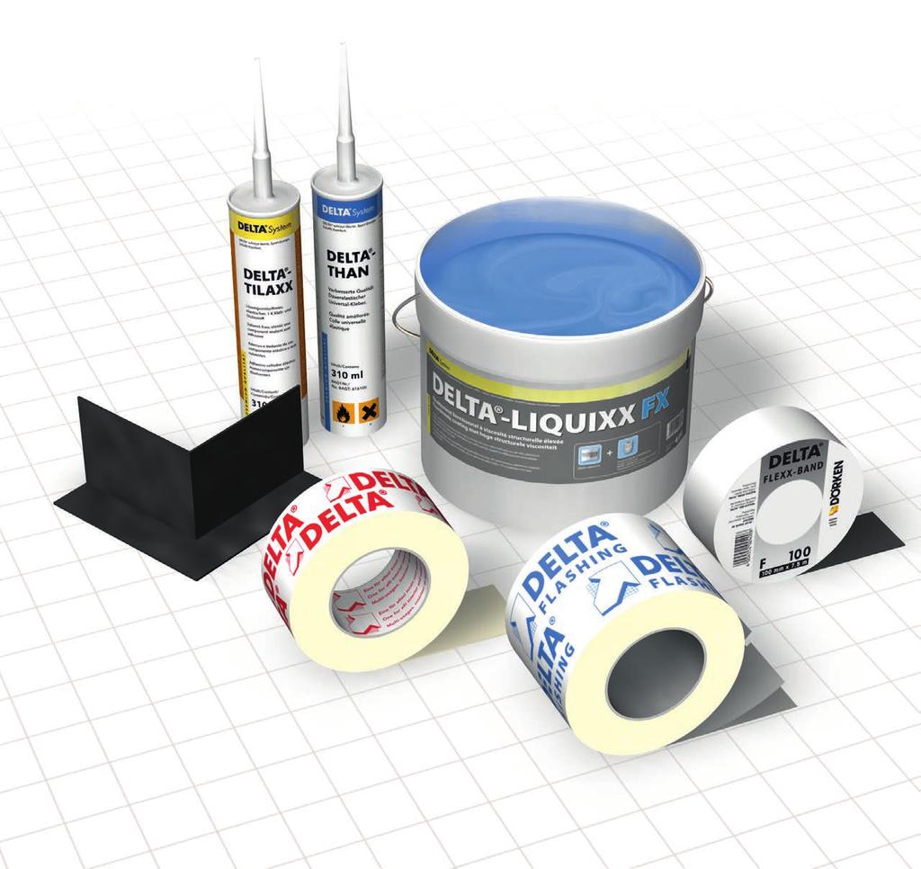
59 59


 Recommended storage: room temperature Surface temperature min. +41 F (+5 C) Recommended storage: room temperature Surface temperature min.")
 Temperature Range -40 F to +176 F (-40 C to +80 C) Size Width: 6\" (15.25 cm), 9\" (23 cm) Length: 75' (22.")
60 DELTA Air Barrier System Components DELTA -FLASHING DELTA -MULTI-BAND DELTA -FLEXX-BAND DELTA -FAS CORNER Premium self-adhesive flashing membrane with aggressive tack. Universal adhesive tape that sticks tenaciously and is highly resistant to aging. Stretchable butyl-rubber compound tape with special carrier membrane. Flexible pre-fabricated window corner. Permanently UV resistant. Recommended Use For flashing of window and door openings. Recommended Use For all DELTA membranes to seal laps and penetrations. Recommended Use Stretchable flashing for details and penetrations. Pre-stretch where required. Recommended Use Provides reliable air- and watertight window details. Surface temperature min. +41 F (+5 C) Recommended storage: room temperature Surface temperature min. +41 F (+5 C) Recommended storage: room temperature Surface temperature min. +41 F (+5 C) Recommended storage: room temperature Temperature Range -40 F to +176 F (-40 C to +80 C) Temperature Range -40 F to +176 F (-40 C to +80 C) Temperature Range -40 F to +176 F (-40 C to +80 C) Temperature Range -40 F to +176 F (-40 C to +80 C) Size Width: 6" (15.25 cm), 9" (23 cm) Length: 75' (22.85 m) Size Width: 2 3/8" (6 cm), 4" (10 cm) Length: 82' (25 m) Size Width: 4" (10 cm) Length: 33' (10 m) Measurements 7" x 7" x 4" (18 cm x 18 cm x 10 cm) 60


 Application Conditions Open time: 30 minutes at min. +41 F (+5 C) Application Conditions Open time: 3-4 hours at +70 F (+21 C) and 45 % RH Surface temperature Application conditions: min.")
61 DELTA -THAN DELTA -TILAXX DELTA -LIQUIXX DELTA -ADHESIVE LVC Permanently elastic special rubber compound sealant and adhesive. High quality permanently elastic adhesive and sealant that retains flexibility. Viscous, pure acrylic dispersion with enclosed fabric reinforcement. Low solvent surface conditioner. Recommended Use For sealing and adhering of DELTA membranes. Provides greater security in detail areas. Suitable for areas with minimal movement of components. Recommended Use For durable air-tight bonding to all common construction surfaces where moderate movement of components is expected. Suitable for sealing of openings around windows (installed with backer rod). Recommended Use For air-tight connection of complex details and air barrier continuity. Suitable for all common construction surfaces. Recommended Use Consolidates surface dust on dirty construction site substrates assuring reliable long-term air-tight adhesion. Compliant with OTC rules for industrial adhesives and sealants and California South Coast Rule Application Conditions Open time: 30 minutes at min. +41 F (+5 C) Application Conditions Open time: 30 minutes at min. +41 F (+5 C) Application Conditions Open time: 3-4 hours at +70 F (+21 C) and 45 % RH Surface temperature Application conditions: min. +25 F (-4 F) Recommended storage: min. 32 F (0 C) Application Rate Approx. 23' (7 linear m) per cartridge Application Rate Approx. 23' (7 linear m) per cartridge Application Rate Approx. 2.8 fl.oz/sqft (0.9 l/sqm) Application Rate Up to 250 sqft/gal (6.13 sqm/l) depending on porosity and texture of surface Temperature Range -22 F to +176 F (-30 C to +80 C) Temperature Range -22 F to +176 F (-30 C to +80 C) Temperature Range -22 F to +176 F (-30 C to +80 C) Temperature Range -40 F to +176 F (-40 C to +80 C) Size 10.5 fl.oz (310 ml) Size 10.5 fl.oz (310 ml) Size 0.66 gal/pail (2.5 l/pail) Size 4.5 gal (17 l) l 61
62 References and Resources For more information on DELTA -VENT SA, please visit: For more information on the design of air barrier systems for commercial and residential construction: Building Science Insight 001: The Perfect Wall Building Science Digest 011: Thermal Control in Buildings Building Science Digest 013: Rain Control in Buildings Building Science Digest 014: Air Flow Control in Buildings Building Science Digest 163: Controlling Cold-Weather Condensation Using Insulation Canadian Building Digest 23: Air Leakage in Buildings Building Science for Building Enclosures, John Straube, PhD, Eric Burnett, PhD, Building Science Press For general building science information: Canadian Building Science Digests

63 DELTA -iselect Software tool to select the optimum Water-resistive Barrier and Rainscreen DELTA protects property. Saves energy. Creates comfort. DELTA -iselect A selection tool for optimum Water-resistive Barrier and Rainscreen. Wall assemblies with various cladding types in different climates demand the proper selection of water-resistive barriers for optimal wall performance. This can be a daunting task for any designer, as there has been virtually no information available to substantiate the decision. DELTA -iselect, a WUFI-based software tool, makes this selection process simple. DELTA iselect analyzes the hygrothermal performance of various wall assemblies. It takes into account the effect of wall components and climatic conditions and the interaction with different water-resistive barriers on the overall wall performance. Based on complex algorithms, the selection tool helps the designer to simply and effortlessly choose the most suitable WRB for a particular wall configuration. Furthermore, DELTA -iselect provides a design recommendation for optimal wall performance. To get your copy of DELTA -iselect on a USB drive, contact us at technical@cosella-dorken.com. 63
Incorporating Insulating Sheathing into the Design of the Thermal and Moisture Management System of the Building Enclosure
 Incorporating Insulating Sheathing into the Design of the Thermal and Moisture Management System of the Building Enclosure Peter Baker, Building Science Corporation ABSTRACT With rising utility cost, concerns
Building Science Control Layer Glossary. Façade Visible exterior face of a building, usually vertical or nearly so, but imprecisely used.
 It is far more important than often appreciated to use precise, unambiguous, clear definitions when describing aspects of buildings, building enclosures, and building science performance. The following
Welcome to this continuing education seminar. This is the first of two parts of the High- Performance Building series.
 Welcome to this continuing education seminar. This is the first of two parts of the High- Performance Building series. 1 3 6 7 8 An enclosure s basic function is to separate the outside from the inside.
Boundaries and Barriers
 Overview of Presentation Boundaries and Barriers High Performance Enclosures Dr John F. Straube Dupont Young Professor School of Architecture & Dept of Civil Engineering University of Waterloo Ontario,
Foundations. Issue. Slab-On-Grade Liquid Water Control (See Figure 2-2) Goals. Guidance
 Goals. Guidance") www.epa.gov/iaq/moisture Foundations Issue Building foundations are vulnerable to moisture problems for a number of reasons, including: Water from rain and from plumbing leaks is drawn by gravity to foundations,
www.epa.gov/iaq/moisture Foundations Issue Building foundations are vulnerable to moisture problems for a number of reasons, including: Water from rain and from plumbing leaks is drawn by gravity to foundations,
How-to: Commissioning Design Reviews for the Building Envelope
 AABC Commissioning Group AIA Provider Number 50111116 How-to: Commissioning Design Reviews for the Building Envelope Course Number: CXENERGY1625 Stevan Vinci, BECxP, LEED AP, Morrison Hershfield Maurya
Thermal Control in Buildings by John Straube (updated )
") building science.com 2006 Building Science Press All rights of reproduction in any form reserved. Building Science Digest 011 Thermal Control in Buildings 2006-11-02 by John Straube (updated 2011-12-12)
building science.com 2006 Building Science Press All rights of reproduction in any form reserved. Building Science Digest 011 Thermal Control in Buildings 2006-11-02 by John Straube (updated 2011-12-12)
New Air and Vapor Barrier Technologies
 New Air and Vapor Barrier Technologies Dr John Straube Dupont Young Professor Associate Professor of Building Science Civil Engineering Dept and School of Architecture University of Waterloo Waterloo,
Thermal Control Layers: Insulation Materials and Systems
 Thermal Control Layers: Insulation Materials and Systems All materials and layers in a building assembly have some resistance to heat flow. However, materials with an R-value of about 2/inch or more (k-value
 Thermal Patterns Created By Moisture Accumulation Within Exterior Masonry Walls by A. Colantonio* and G. Desroches ** * Public Works And Government Services Canada, Ottawa, Canada ** Public Works And Government
2006 Building Science Press All rights of reproduction in any form reserved.
 building science.com 2006 Building Science Press All rights of reproduction in any form reserved. Building Science Digest 011 Thermal Control in Buildings 2006-11-07 by John Straube Abstract: Providing
3/24/2017. Kohta Ueno. Building Science of Walls. March 24, Background Rhode Island AIA Presentation 2
 Kohta Ueno Building Science of Walls March 24, 2017 Background 2017-03 Rhode Island AIA Presentation 2 1 Environmental Separator 2017-03 Rhode Island AIA Presentation 3 What Separation Roles? Water control
Vapour Diffusion for Residential Construction. Canada and Northern USA VAPOUR DIFFUSION FOR RESIDENTIAL CONSTRUCTION CANADA AND NORTHERN USA
 VAPOUR DIFFUSION FOR RESIDENTIAL CONSTRUCTION CANADA AND NORTHERN USA Vapour Diffusion for Residential Construction Canada and Northern USA Brookfield Homes, Niagara, Ontario VAPOUR DIFFUSION FOR RESIDENTIAL
Adhered Veneers and Inward Vapor Drives: Significance, Problems and
 Feature Adhered Veneers and Inward Vapor Drives: Significance, Problems and Solutions By Dr. John Straube, P.Eng., Chris Schumacher, Jonathan Smegal and Marcus Jablonka Adhered veneers, in which masonry
Welcome to this continuing education seminar. This is the first of three parts of the Building Enclosure Fundamentals series.
 Welcome to this continuing education seminar. This is the first of three parts of the Building Enclosure Fundamentals series. 1 3 6 7 8 The primary reasons to build airtight buildings are to avoid drafts
WeatherSmart Air Barrier Installation Guide
 WeatherSmart Air Barrier Installation Guide 1 The intent of this document is to provide a guide for the installation of WeatherSmart as both a Weather Resistive Barrier (W.R.B.) and an Air Barrier Material
Adhered Veneers and Inward Vapor Drives: Significance, Problems and
 Feature Adhered Veneers and Inward Vapor Drives: Significance, Problems and Solutions By Dr. John Straube, P.Eng., Chris Schumacher, Jonathan Smegal and Marcus Jablonka ADHERED VENEERS, IN WHICH MA- SONRY
INSTALLING WATER-RESISTIVE BARRIERS & FLASHING
 INSTALLING WATER-RESISTIVE BARRIERS & FLASHING IN A TWO-LAYER STUCCO APPLICATION Fortifiber Building Systems Group provides this guide to assist installers by demonstrating a two-layer installation of
Why Control Heat flow? How to Control Heat Flow? Thermal Performance. Modes of heat transfer: Thermal Control: Insulation & Thermal Bridges
 Fundamentals Insulation and Thermal Bridges June 13-14, 2012 Why Control Heat flow? Joseph Lstiburek, Ph.D., P.Eng John Straube, Ph.D., P.Eng 2012 Thermal Control: Insulation & Thermal Bridges 1. Occupant
8/14/2015. Course Description. Course Objectives AIR, WATER, AND MOISTURE MANAGEMENT IN LIGHT COMMERCIAL BUILDING ENVELOPES
 AIR, WATER, AND MOISTURE MANAGEMENT IN LIGHT COMMERCIAL BUILDING ENVELOPES Traditional and Next Generation Solutions New England Building Officials Education Association Conference October 5-7, 2015 Course
Vapor Barriers and Air Barriers
 Vapor Barriers and Air Barriers By: John Straube The single most common building science question I get from builders, engineers, code officials and architects is "Do I need a vapor barrier?". The queries
The Disclaimer located on the reverse side of the title page of the OAA Rain Penetration Practice Guide applies to each section of the Guide.
 Note: This document has been divided into several sections in order to suit the limitations of the website. The Disclaimer located on the reverse side of the title page of the OAA Rain Penetration Practice
New Approaches to Energy Efficiency & Green Building. Who is Icynene Inc.? World-Wide Distribution. The Icynene Insulation System
 The Icynene Insulation System New Approaches to Energy Efficiency & Green Building Control of Air Leakage and Moisture Vapour Transmission Who is Icynene Inc.? Founded in November, 1986 in Toronto Canada
BUILDING ENCLOSURE AIR TIGHTNESS TESTING Course Number: BCLUNA018-01P
 BUILDING ENCLOSURE AIR TIGHTNESS TESTING Course Number: BCLUNA018-01P Provider Number:404108121 Darek Brandt, PE Chief Engineer, Building Science Solutions AIA CES DISCLAIMER Credit(s) earned on completion
Building Enclosure Concept Design Checklist
 Building Enclosure Concept Design Checklist SUPPORT. Support mechanical loads Sufficient strength and stiffness (from structural engineer) CONTROL. Heat Flow Control (Temperature and Energy) avoid thermal
Innovative Passive Ventilation Water-Resistive Barriers How Do They Work?
 building science.com 2010 Building Science Press All rights of reproduction in any form reserved. Innovative Passive Ventilation Water-Resistive Barriers How Do They Work? Conference Paper - 1010 13 December
The Role of Control Layers in Building Enclosure Design
 The Role of Control Layers in Building Enclosure Design COLIN SHANE M.ENG., P.ENG. ASSOCIATE, SENIOR PROJECT MANAGER OCTOBER 13, 2016 Disclaimer: This presentation was developed by a third party and is
Background. Building Science of Walls. Environmental Separator. What Separation Roles? 1/25/2018. January 25, 2018
 Kohta Ueno Background Building Science of Walls January 25, 2018 2018-01 Deering Lumber Presentation 2 Environmental Separator What Separation Roles? Water control layer A.k.a. drainage plane, water resistive
MOISTURE VAPOR MOVEMENT AND VAPOR PERMEANCE
 HOW VAPOR RESISTANCE PROPERTIES OF COATINGS AFFECT EXTERIOR WALL MOISTURE PERFORMANCE Garth D. Hall, Senior Architect, AIA, Kenneth M. Lies, Principal, AIA, and Sarah K. Flock, Architect III Raths, Raths,
Moisture Considerations for Insulated Building Assemblies
 PHRC Webinar Series Tuesday, November 10, 2015 @ 1pm Description Moisture Considerations for Insulated Building Assemblies Brian Wolfgang Housing Systems Specialist One critical design consideration in
Better Buildings. Performance. Fundamentals. The Rules
 Fundamental Goals Dr John Straube, P.Eng. Principal, Building Science Corporation Associate Professor, University of Waterloo Better Buildings Fundamentals Safe Healthy Comfortable Durable Affordable Environmentally
6. Moisture Design. Objectives: 3. Prevent vapor condensation (surface, concealed) 4. Prevent rain penetration
 4. Prevent rain penetration") 6. Moisture Design Objectives: 3. Prevent vapor condensation (surface, concealed) 4. Prevent rain penetration Vapor Condensation More new bldgs are susciptable to vapor condensation because of: 2. 1. 2.
6. Moisture Design Objectives: 3. Prevent vapor condensation (surface, concealed) 4. Prevent rain penetration Vapor Condensation More new bldgs are susciptable to vapor condensation because of: 2. 1. 2.
Building Science Fundamentals Thermal Control: Insulation & Thermal Bridges May 29-30, Straube buildingscience.com 1 of 24
 Fundamentals Thermal Control: Insulation & Thermal Bridges May 29-30, 2013 Straube buildingscience.com 1 of 24 Fundamentals Thermal Control: Insulation & Thermal Bridges May 29-30, 2013 Straube buildingscience.com
Building Science.com Building Science.com Building Science.com
 Dr John Straube, P.Eng. Associate Professor, University of Waterloo Principal, Building Science Corporation Western Building Tradition Adventures in Building Science Enclosures www.buildingscience.com
Insulated Metal Panel (IMP) Systems
 Systems") METL-SPAN Joseph Lstiburek, Ph.D., P.Eng. November, 2015 Table of Contents 1. Physics of Building Enclosures... 4 2. Physics of Insulated Metal Panels... 12 3. Joint Design... 19 4. Thermal Bridging...
METL-SPAN Joseph Lstiburek, Ph.D., P.Eng. November, 2015 Table of Contents 1. Physics of Building Enclosures... 4 2. Physics of Insulated Metal Panels... 12 3. Joint Design... 19 4. Thermal Bridging...
Pre-WWII Buildings. Performance? Environmental Separation. Mold, Rot, Corrosion, Decay, Recladding
 Pre-WWII Buildings John Straube, Ph.D., P.Eng 2013 Environmental Separation No added insulation (or very little) Heating systems and some natural ventilation No air conditioning No vapor barriers Few explicit
Water control Vapor control and drying Room for growth
 How do we decide whether to insulate to inside or the outside? How to install windows in a DER wall (let me count the ways ) What s the best approach for historic buildings? How to deal with basement walls
Introduction. Introduction. Designing Building Envelopes to Meet Sustainable and Aesthetic Goals Part 1
 Designing Building Envelopes to Meet Sustainable and Aesthetic Goals Part 1 Brian Miller, P.E., LEED AP Precast/Prestressed Concrete Institute Brad Nesset Thermomass Introduction Webinar is in two parts
FirstEnergy Program Overview
 FirstEnergy Program Overview Builder incentives $400 per unit + $0.10/kWh in projected savings Eligibility Located in service area of a FirstEnergy Utility Certificate of Occupancy Dates: FirstEnergy Ohio
AIR BARRIER SYSTEMS VAPOR-PERMEABLE AND NON-PERMEABLE. Sealed, Smart, and Sustainable WATERPROOFING & BUILDING PRODUCTS COMMERCIAL PRODUCT
 WATERPROOFING & BUILDING PRODUCTS COMMERCIAL PRODUCT VAPOR-PERMEABLE AND NON-PERMEABLE AIR BARRIER SYSTEMS Sealed, Smart, and Sustainable Environmentally friendly and ecologically sound Effective, efficient
Rain. Building Science. Rain is the largest source of moisture We need better control for better insulation and airtightness Rain penetration control
 Rain Control Layer Air Control Layer Vapor Control Layer Thermal Control Layer Rain Control 1 Rain Control 2 Rain Rain Control Rain is the largest source of moisture We need better control for better insulation
Building Enclosure Design Fundamentals, Components, and Assemblies
 Building Enclosure Design Fundamentals, Components, and Assemblies COLIN SHANE M.ENG., P.ENG., P.E. PRINCIPAL, SENIOR PROJECT MANAGER RDH BUILDING SCIENCE INC. JULY 11, 2018 Disclaimer: This presentation
Moisture Safe? The Writings on the Wall
 Kohta Ueno Moisture Safe? The Writings on the Wall Credit(s) earned on completion of this course will be reported to AIA CES for AIA members. Certificates of Completion for both AIA members and non AIA
in the industry that highly permeable membranes are superior to less-permeable alternatives. This is not always the case.
 Editor s Note: A modified version of this paper was originally presented at the RCI, Inc. 31st International Convention & Trade Show in Orlando, Florida, in March 2016. introduction Vapor diffusion is
Basements are Changing. Basements Part of the Enclosure. Basements. Control: Moisture. Moisture: Old ideas. Energy Efficient, Durable, Healthy
 Basements are Changing John Straube, Ph.D., P.Eng Basements: New & Retrofit Energy Efficient, Durable, Healthy Building Science Corporation presented by www.buildingscience.com Increasingly used as living
Building Enclosure Detailing for Walls and Low-Sloped Roofs
 Building Enclosure Detailing for Walls and Low-Sloped Roofs COLIN SHANE M.ENG., P.ENG., P.E. ASSOCIATE, SENIOR PROJECT MANAGER RDH BUILDING SCIENCE INC. AUGUST 2016 Disclaimer: This presentation was developed
Evolution of Wall Design for Controlling Rain Penetration
 Construction Technology Update No. 9 Evolution of Wall Design for Controlling Rain Penetration by G.A. Chown, W.C. Brown and G.F. Poirier The design of walls to control rain penetration has changed considerably
RESIDENTIAL INSULATED SHEATHING INSTALLATION GUIDE. Residential Insulated Sheathing Installation Guide ROXUL COMFORTBOARD 80
 RESIDENTIAL INSULATED SHEATHING INSTALLATION GUIDE Residential Insulated Sheathing Installation Guide ROXUL COMFORTBOARD 80 Contents Introduction How to Use this Guide...1 Split-Insulation Wall Assembly...2
Smart Vapor Retarders
 CertainTeed Smart Vapor Retarders Insulation B UILDING S CIENCE SMART VAPOR RETARDERS: A TECHNOLOGY PRIMER For years, builders have relied on a dual climate-zone classification for the placement of vapor
Assessing the Impact of US Housing. Retrofits. Building Carbon Emissions. Building Energy Use. buildingscience.com
 ! 2008! Retrofits Commercial Institutional Assessing the Impact of US Housing Background:! Total Housing Units in 2001 (millions): Single-Family Homes 73.7 Apartments (all buildings) 26.5 Mobile Homes
Technicalbulletin #16
 air barriers Technicalbulletin #16 Introduction The movement of moisture 1 can cause problems with the performance of the building envelope through two mechanisms; condensation of water vapor and bulk
NOVAWRAP ASPIRE Q & A
 TM NOVAWRAP ASPIRE i build with What is building wrap and why should I use NovaWrap Aspire? A building wrap like NovaWrap Aspire is a critical element in the building envelope system which is the physical
Basements: New & Retrofit
 John Straube, Ph.D., P.Eng Basements: New & Retrofit Energy Efficient, Durable, Healthy Building Science Corporation presented by www.buildingscience.com This presentation Basement functions Basement Performance
Innovating Continuous Exterior Insulation. Theresa A. Weston, PhD. 1
 ABSTRACT Innovating Continuous Exterior Insulation Theresa A. Weston, PhD. 1 As the need to reduce energy usage and carbon consumption has increased, the need for energy efficient building envelopes has
Solid masonry. Healthy, Durable, More Sustainable Buildings: Five Big Changes in Buildings over the last 50 years
 Solid masonry Dr John Straube, P.Eng. Associate Professor, University of Waterloo Healthy, Durable, More Sustainable Buildings: Five Big Changes in Buildings over the last 50 years www.buildingscience.com
2006 INTERNATIONAL ENERGY CONSERVATION CODE
 2006 INTERNATIONAL ENERGY CONSERVATION CODE DOCUMENTATION Code Change No: EC28-06/07 Original Proposal Sections: IECC: 202, 402.5, 402.5.1 (New), Table 402.5.1 (New), 402.5.2 (New), 402.5.3 (New), 402.2.8,
The Building Envelope Defined
 Learning Objectives 1. The purpose of the building envelope 2. The energy code s definition of the building envelope 3. The exterior forces that act on the building envelope 4. The interior forces that
New Opportunities For Spray Polyurethane Foam
 New Opportunities For Spray Polyurethane Foam Presented by: Len Anastasi EXO-TEC Consulting, Inc. www.exo-tec.biz len@exo-tec.biz Recent Building Code Changes 2006 International Energy Code Increases insulation
Pre-WWII Buildings. Performance? Why High Performance? Green? Environmental Separation
 Roxul Consulting Day Enclosures August 30, 2012 Pre-WWII Buildings John Straube, Ph.D., P.Eng Roxul Environmental Separation No added insulation (or very little) Heating systems and some natural ventilation
EE13-3 Improving Building Enclosures Thermal Performance as a Goal of Energy Efficiency. Paul E. Totten, PE Marcin Pazera, Ph. D.
 EE13-3 Improving Building Enclosures Thermal Performance as a Goal of Energy Efficiency Paul E. Totten, PE Marcin Pazera, Ph. D. ABSTRACT Energy efficiency of buildings will continue to be a critical factor
Overview of Presentation. Airflow Control: Why. Airflow Control: what kind?
 Overview of Presentation John Straube, Ph.D., P.Eng Air Flow Control Why control airflow? Vapor flow? Review of Driving Forces Air Barrier Systems Functions + Requirements Airflow Within Enclosures convective
This presentation. Basements: New & Retrofit. Basements Part of the Enclosure. Basements are Changing. Basement functions Basement Performance
 This presentation John Straube, Ph.D., P.Eng Basements: New & Retrofit Energy Efficient, Durable, Healthy Building Science Corporation presented by www.buildingscience.com Basement functions Basement Performance
Revised January buildingscience.com. Water Management Details. Housewraps/Flashings/Windows buildingscience.com
 Revised January 2007 Housewraps/Flashings/Windows BSP-020: for Residential Buildings Table of Contents Introduction... 4 Water Management Concept...4 Risk Factors... 4 Building Paper/Housewraps as the
Sloped Roofs vs Walls. Problems. Review Roof Components. University of Waterloo and Balanced Solutions
 Roofs, Cathedral Ceilings, Venting, Non-Vented Dr June, 2005 This presentation Scope: Pitched, Wood, Roofs Performance Problems Vented, cathedral, unvented etc What solutions www.balancedsolutions.com
Condensation - Prevention and Control
 TECHNICAL NOTES on Brick Construction 47 1850 Centennial Park Drive, Reston, Virginia 20191 www.gobrick.com 703-620-0010 June 2006 Condensation - Prevention and Control Abstract: This Technical Note describes
Spray Polyurethane Foam: The Need for Vapor Retarders in Above-Grade Residential Walls
 building science.com 2009 Building Science Press All rights of reproduction in any form reserved. Spray Polyurethane Foam: The Need for Vapor Retarders in Above-Grade Residential Walls Research Report
Heat Flow by direct contact Vibrating molecules Most important for solids 1 > t2 Heat flow
 Fundamentals Heat Control Why Control Heat flow? Joseph Lstiburek, Ph.D., P.Eng John Straube, Ph.D., P.Eng 2011 Thermal Control: Insulation & Thermal Bridges 1. Occupant Comfort 2. Control surface and
This presentation. Functions of the building enclosure. University of Waterloo and Balanced Solutions. Straube Presentation Building Canada
 Hygrothermal Basement Performance, or Why do we get water when we dig holes in the ground? Dr John Straube October, 2004 This presentation What do basements do Examine performance Why problems What solutions
2013 COMMERCIAL PRODUCTS
 2013 COMMERCIAL PRODUCTS EXPLORE GEOMETRY AND SPACE WITHOUT COMPROMISING BUILDING ENVELOPE PERFORMANCE Commercial design considerations come with very specific challenges that can t be addressed with just
Rainscreen Walls: Field Monitoring and Performance in British Columbia
 Number 6 Builder Insight technical maintenance bulletin Rainscreen Walls: Field Monitoring and Performance in British Columbia Overview In the mid 1990s, widespread moisture problems became apparent in
Field Performance of Spray Polyurethane Foam: The Role of Vapour Diffusion Control
 Field Performance of Spray Polyurethane Foam: The Role of Vapour Diffusion Control Graham Finch, B.A.Sc. & John Straube, Ph.D. Building Engineering Group, Civil Engineering Department, University of Waterloo
EIFS Rain Control EIFS. Face Sealed Perfect Barrier. Beware of EIFS: They must be done correctly They leak at joints Avoid moist sensitive substrate
 EIFS Rain Control Both Drained and Perfect Barrier can be used Joints and Element can be designed differently Face Sealed Perfect Barrier The problem wall of the past Relies on sealant = dangerous Often
Impact of NFPA 285 on Air Barrier Specification and Design
 Impact of NFPA 285 on Air Barrier Specification and Design Charlotte Metzler Amanda Stacy, LEED Green Associate WSP Building Enclosures Air Barrier Association of America (ABAA) is a Registered Provider
Healthy, Durable, Low Energy Buildings: Thermal: High R. Thermal bridges. Fundamentals, techniques, and pitfalls
 Dr John Straube, P.Eng. Associate Professor, University of Waterloo Principal, Building Science Corporation Healthy, Durable, Low Energy Buildings: Fundamentals, techniques, and pitfalls Thermal: High
The Devil is in the Details Learning Objectives! Targets and codes have raised awareness People know you need
 Better Buildings by Design High Performance Enclosure Details Februray 9, 2012 Efficiency Vermont is a Registered Provider with The American Institute of Architects Continuing Education Systems (AIA/CES).
About Insulation & R Value - cmhc.ca
 About Insulation & R Value - cmhc.ca Insulating Your House While previous generations may have been content to live in drafty houses, most people now want comfortable warm houses. A healthy house today
Compliance for Continuous Insulation, Water Resistive Barriers & NFPA-285 What you need to Know
 Compliance for Continuous Insulation, Water Resistive Barriers & NFPA-285 What you need to Know www.dryvit.com 800-556-7752 1 AIA / CES Dryvit Systems, Inc. is a Registered Provider with The American Institute
Insulation Technologies and Installation Specifications for Better Energy Performance of Commercial Buildings
 Insulation Technologies and Installation Specifications for Better Energy Performance of Commercial Buildings Wood Products Council is a Registered Provider with The American Institute of Architects Continuing
U.S. EDITION RESIDENTIAL CONSTRUCTION DETAILS SAMPLE. A visual guide to construction detailing. Emma Walshaw
 RESIDENTIAL CONSTRUCTION DETAILS U.S. EDITION A visual guide to construction detailing Emma Walshaw Contents INTRODUCTION 4 PRINCIPLES OF CONSTRUCTION DETAILING 6 FOUNDATIONS 9 PRINCIPLES OF FOUNDATION
THE PERFECT WALL IN COLD CLIMATES:
 THE PERFECT WALL IN COLD CLIMATES: Solutions with Polyiso CI By Timothy Ahrenholz Figure 1 Polyiso insulation with foil facer. ABSTRACT Have you ever viewed certain building code provisions as impediments
The Influence of Low- Permeance Vapor Barriers on Roof and Wall Performance
 building science.com 2011 Building Science Press All rights of reproduction in any form reserved. The Influence of Low- Permeance Vapor Barriers on Roof and Wall Performance Conference Paper - 1101 25
RESIDENTIAL INSULATED SHEATHING COMFORTBOARD. Installation Guide
 RESIDENTIAL INSULATED SHEATHING TM COMFORTBOARD 80 Installation Guide Table of Contents Introduction How to Use this Guide...1 Split-Insulation Wall Assembly...2 Insulation... 3 Nominal and Effective R-Values
QUANTITATIVELY EVALUATING THE EFFECTIVENESS OF DIFFERENT DRIP EDGE PROFILES
 QUANTITATIVELY EVALUATING THE EFFECTIVENESS OF DIFFERENT DRIP EDGE PROFILES J. Smegal, A. Lukachko, J. Straube and T. Trainor ABSTRACT Proper rainwater management is one of the key factors ensuring long-term
Insulating Basements: Part 1 Fundamentals
 The Pennsylvania Housing Research Center Insulating Basements: Part 1 Fundamentals Builder Brief: BB0510 Brian Wolfgang, PHRC Fellow INTRODUCTION The perception of a basement has changed significantly
Rainscreen Gaps in Exterior Walls
 PHRC Webinar Series Tuesday, September 13 @ 1pm Rainscreen Gaps in Exterior Walls Brian Wolfgang Housing Systems Specialist Pennsylvania Housing Research Center 219 Sackett Building University Park, PA
Dow Corning Silicone Air Barrier System. A more. energy-efficient. shade. green
 Silicone Air Barrier System of shade energy-efficient A more green Air and Moisture Protection for More Energy-Efficient Buildings Meeting regulatory requirements for energy efficiency is a significant
Required effective insulation values are available on information sheets for each climactic zone.
 Section 9.36. Permit Application Information Required on Submitted Drawings Section 9.36 Building Permit Application Guideline Section 9.36 of the Alberta Building Code came into force Nov 1, 2016. The
Brussels Window. Good Windows. Windows. Objectives. Why Good Windows? Windows. Need to control. Learn. Functions: Same as wall - plus.
 Good Windows Brussels Window Dr John Straube Dupont Young Professor Civil Eng Dept and School of Architecture University of Waterloo Waterloo, Ont Canada jfstraube@uwaterloo.ca Windows Objectives Need
Insight. Joseph Haydn Does The Perfect Wall. By Joseph W. Lstiburek, Ph.D., P.Eng., Fellow ASHRAE
 Insight Joseph Haydn Does The Perfect Wall An edited version of this Insight first appeared in the ASHRAE Journal. Figure 1: Perfect Wall Control layers located exterior to the structure. By Joseph W.
Insulation. First Revison October DC14 Drainage Mat INSTALLATION GUIDE FOR RESIDENTIAL & COMMERCIAL APPLICATIONS
 Insulation First Revison October 2016 DC14 Drainage Mat INSTALLATION GUIDE FOR RESIDENTIAL & COMMERCIAL APPLICATIONS 1. General Information This Guide describes the use of Kingspan GreenGuard DC14 Drainage
Rainscreen Description Manual
 Rainscreen Description Manual BUILDING ENVELOPE ENGINEERING 1058 Daley Street Edmonds, WA 98020 Phone: (425) 672-3900 Fax: (425) 712-8608 BEE-Engineers.com Page 2 of 15 TABLE OF CONTENTS History 3 Rainscreen
Building America Special Research Project: High-R Walls Case Study Analysis
 building science.com 2009 Building Science Press All rights of reproducti on in any form reserved. Building America Special Research Project: High-R Walls Case Study Analysis Building America Report -
1 Exam Prep Prov Module: Thermal and Moisture Protection Questions and Answers
 1 Exam Prep Prov Module: 27203-13 Thermal and Moisture Protection Questions and Answers 1. The R-value is a measure of the ability of a material to. A. Resist the passage of moisture B. Resist heat conduction
Continuous Insulation and Air Barriers for High Performance Walls
 Continuous Insulation and Air Barriers for High Performance Walls www.dryvit.com 800-556-7752 1 AIA / CES Dryvit Systems, Inc. is a Registered Provider with The American Institute of Architects Continuing
When R-Value Doesn t Measure Up
 C. J. Schumacher B.Tech (Arch.Sci.), B.A.Sc.(Civ.Eng.), M.A.Sc.(Bldg.Sci.) When R-Value Doesn t Measure Up NESEA Building Energy10 Outline Why R-Values? Heat, Temperature & Heat Flow Insulating Materials
Index. STP779-EB/Jul. 1982
 STP779-EB/Jul. 1982 Index A Absorption of moisture (see Moisture absorption) Adsorption, 191 Capillary versus time, 197 Isotherms For glass fiber, 194, 195 For various materials, 196 Air leakage (exfiltration,
Air Sealing for 5 ACH 50
 November 13th, 2018 Christopher Hine Air Sealing for 5 ACH 50 www.phrc.psu.edu Provider # 60114115 PPP ID: 1562 November 13th, 2018 Christopher Hine Air Sealing for 5 ACH 50 www.phrc.psu.edu Provider #
2001 National Workshop on State Building Energy Codes July th, 2001 Burlington, Vermont
 2001 National Workshop on State Building Energy Codes July 16-19 th, 2001 Burlington, Vermont A Systems Engineering Approach to the Design of Energy and Resource Efficient Homes Presented By: Mark LaLiberte
Mark Lawton, P.Eng., FEC. Airtightness in Buildings A Canadian History June 2017
 Mark Lawton, P.Eng., FEC Airtightness in Buildings A Canadian History June 2017 History of What? Understanding Measurement Implementation Air in Buildings Carries moisture to cold surfaces where condensation
INSIDE WHY SPRAY POLYURETHANE FOAM INSULATION?
 INSIDE WHY SPRAY POLYURETHANE FOAM INSULATION? SUSTAIN THROUGH KNOWLEDGE BOOK 1: WHY SPRAY POLYURETHANE FOAM INSULATION BOOK 2: SPF & THERMAL BARRIER SPF & SAFETY PERSONAL PROTECTIVE EQUIPMENT BOOK 3: