Insulated Metal Panel (IMP) Systems
|
|
|
- Harold Barber
- 5 years ago
- Views:
Transcription

1 METL-SPAN Joseph Lstiburek, Ph.D., P.Eng. November, 2015
2 Table of Contents 1. Physics of Building Enclosures Physics of Insulated Metal Panels Joint Design Thermal Bridging Wall Systems Punched Openings Continuity Control Layers Roof to Wall Connection Continuity Control Layers Foundation to Wall Connection Retrofit Approaches Comparison With Alternative Systems
3 Table of Figures Figure 1: Environmental Loads... 4 Figure 2: Perfect Wall... 5 Figure 3: Physics of Walls and Roofs and Slabs... 6 Figure 4: Control Layers in Roof Assemblies... 7 Figure 5: Control Layers in Slab Assemblies... 7 Figure 6: Conceptual Approach to a Building Enclosure... 8 Figure 7: Conceptual Approach to a Building Enclosure... 8 Figure 8: Conceptual Approach to a Building Enclosure... 9 Figure 9: Conceptual Approach to a Building Enclosure... 9 Figure 10: Conceptual Approach to a Building Enclosure Figure 11: Conceptual Approach to a Building Enclosure Figure 12: Conceptual Approach to a Building Enclosure Figure 13: Site Built Perfect Wall or Universal Wall Figure 14: Site Built Perfect Wall or Universal Wall Figure 15: Pre-Manufactured Perfect Wall or Universal Wall Figure 16: Face - Clad Insulated Metal Panel Figure 17: Insulated Metal Panel With Cavity Insulation Figure 18: Face Clad Insulated Metal Panel With Cavity Insulation Figure 19: Site Built Compact Roof Assembly Figure 20: Pre-Manufactured Roof Assembly Figure 21: Horizontal Wall Panel Joint Figure 22: Vertical Wall Panel Joint Figure 23: Vertical Wall Panel Joint for Low Rain Loads Figure 24: Roof Panel Joint Figure 25: Controlling Thermal Bridging Figure 26: Controlling Thermal Bridging Figure 27: Controlling Thermal Bridging in Wall Panels Figure 28: Controlling Thermal Bridging in Vertical Wall Panels Figure 29: Controlling Thermal Bridging in Roof Panels Figure 30: Face Clad Insulated Metal Panel Water Control Figure 31: Continuity of the Water Control Layer Figure 32: Drained Air Gap Brick Veneer Figure 33: Drained Air Gap Terra Cotta Cladding Figure 34: Drained Air Gap Metal Panel Cladding Figure 35: Window Head Figure 36: Window Jamb Figure 37: Low Parapet Assembly Figure 38: High Parapet Assembly Figure 39: Base Overhang Figure 40: Notched Foundation
4 Figure 41: Insulated Metal Panel Retrofit of a Mass Wall Figure 42: Cavity insulated metal building and steel stud assemblies and externally insulated metal building and steel stud assemblies Figure 43: Conductivity of the steel framing/steel studs Figure : Air leakage through and around improperly installed internal frame or cavity insulation Figure 45: Blanket insulation purlin roof systems Figure 46: Face-sealed masonry block assemblies Figure 47: Cavity insulated wood frame assemblies and externally insulated/cavity insulated wood frame assemblies Figure 48: Uninsulated and Externally Insulated Mass Wall Systems Figure 49: Sinusoidal External Temperature Swing With Steady Amplitude Figure 50: Non Steady Diurnal External Temperature Swings
5 1. Physics of Building Enclosures At a fundamental level a building can be considered an environmental separator. It keeps the outside out and the inside in. While it is doing this it shouldn t burn, be blown away or fall down. The following discussion focuses on the environmental separation aspects of building enclosures and not the fire control and structural aspects. The environmental loads are graphically presented in Figure 1. Historically they have been characterized as combined heat, air and moisture (HAM) transport. More recently they are referred to as hygrothermal loads and the process of evaluating their effect on building enclosures is called hygrothermal analysis. The following list defines the key hygrothermal control requirements for building enclosures: Control heat flow Control airflow Control water vapor flow Control rain Control ground water These control requirements are governed by the Laws of Thermodynamics. Of the four Laws of Thermodynamics the 2 nd Law is the most misunderstood and most relevant to environmental separation. The 2 nd Law can be summarized as follows: Heat flow is from warm to cold Moisture flow is from warm to cold Moisture flow is from more to less Airflow is from a higher pressure to lower pressure Gravity acts down Figure 1: Environmental Loads Typical hygrothermal loads acting on building enclosures. The loads act on both sides of the assembly, from the exterior and the interior. Applying the 2 nd Law to the hygrothermal control requirements yields the following control layers. Water control layer Air control layer Vapor control layer Thermal control layer 4
 has been the focus of master builders and architects for generations. Controlling air is a much more recent focus less than a century.")

6 These control layers are listed in order of importance. All are important, but not equally important. The ranking is obvious from historic experience and the underlying physics. Controlling water in the liquid form (rain and ground water) has been the focus of master builders and architects for generations. Controlling air is a much more recent focus less than a century. Controlling vapor is even more recent less than a generation. Air movement transports significantly more water in the vapor form than does vapor diffusion and therefore air control is more important than the control of molecular water vapor transport vapor diffusion. In common parlance Air barriers are more important than vapor barriers. Thermal control dates back millenniums but getting it wrong has not led to durability failures. The thermal control layer failures have been typically limited to comfort issues and operating cost issues. Hence, thermal control layers are listed last on the control layer priority list. The optimum configuration of the control layers for a wall assembly is graphically presented in Figure 2. Figure 2: Perfect Wall The optimum configuration of the control layers for a wall assembly. The water control layer, air control layer and vapor control layer are all located on the exterior of the structure. These three have been traditionally combined into a single control layer that can be a film or coating or membrane or a sheet good. The fourth control layer, the thermal control layer is located exterior to the other three control layers. This configuration, with the thermal control layer outboard of the water, air and vapor control layers, allows this assembly to be constructed in all climate zones: cold, mixed, hot and humid or dry. Additionally, this configuration allows this assembly to enclose all interior environments in all climate zones: office, commercial, residential, institutional, pools, museums, art galleries, data processing centers. The sole exception are refrigerated buildings and cold storage facilities. In such assemblies the location of the thermal control layer is flipped with the other control layers the thermal control layer now becomes located on the interior of the other three control layers. In cold climates locating the vapor control layer on the interior of the thermal control layer results in this layer remaining warm therefore controlling condensation from occurring due to interior moisture sources. In hot climates locating the vapor control layer on the exterior of the structure allows the drainage of condensation to the exterior condensation that may occur on the exterior surface of the control layer due to exterior moisture surfaces. This condensed water is handled in the same manner as penetrating rainwater. Note that the water control layer and vapor control layer are in the same location and are typically the same material. In mixed climates the configuration addresses interior moisture loads during the heating season in the same manner a similar assembly addresses interior moisture loads in cold climates. During the cooling season the configuration addresses exterior moisture loads in the same manner a similar assembly addresses exterior moisture loads in hot climates. For this reason, this configuration is referred to as the universal wall or the perfect wall. It works in all climate zones for all interior environmental conditions with the exception noted. This configuration does not require any hygrothermal analysis (such as Warme und Feuchte instationar WUFI modeling) in any climate zone. In cold climates or in any climate zone during heating months dew point calculations or hygrothermal modeling are not necessary regardless of the interior moisture load as all of the insulation is external to the air control and vapor control layer. In hot humid climates or any climate where air conditioning is occurring dew point calculations or 5

7 hygrothermal modeling again are not required as condensation can only occur, if it occurs at all, on the exterior surface of the water, air and vapor control layer where it can drain to the exterior in the same manner that rain penetration is controlled. The only stipulation is to not include a vapor barrier to the interior of the assembly. The function of the cladding is four-fold: protect the control layers from exposure to ultra-violet radiation reduce the rain load on the control layers provide physical protection to the control layers provide aesthetics The cladding is drained and back-ventilated in such assemblies. The function of the drainage is to control hydrostatic pressure that may result from penetrating rainwater. The function of the back-ventilation is to reduce inward vapor drive than may occur from reservoir claddings claddings that are wetted during rain events that may store moisture and then exposed to solar radiation. The same approaches can be applied to roofs and foundations the argument being that similar loads and the same laws of physics apply (Figure 3). Figure 3: Physics of Walls and Roofs and Slabs Similar loads and the laws of physics apply to all elements of the building enclosure. The traditional configuration for the control layers of a roof assembly is graphically presented in Figure 4. Control layers are provided above and below the thermal control layer. The typical roof membrane functions as the water control layer, an air control layer and a vapor control layer above the thermal control layer the insulation. A second membrane or layer or layers are provided below the thermal control layer the insulation and the function of this membrane or layers is to function as an air control layer and vapor control layer. The intent is to keep the rain and air and vapor from getting into the assembly from the top ( outside ) and to keep the air and vapor from getting into the thermal control layer from the bottom ( inside ). This configuration also works in all climate zones and for all interior environmental conditions even for refrigerated buildings and cold storage facilities. 6

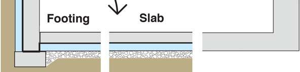
8 Figure 4: Control Layers in Roof Assemblies Control layers are provided above and below the thermal control layer. The intent is to keep rain, air and vapor from entering the assembly from the top side and to keep air and vapor from entering the assembly from the bottom side. The optimum configuration of the control layers for a foundation slab assembly is graphically presented in Figure 5. The key to the performance of this assembly is the granular or stone layer under the thermal control layer (the insulation ) that functions as a capillary break controlling liquid water absorption in the thermal control layer. It is analogous to the drained and back-ventilated cladding of a wall assembly. Figure 5: Control Layers in Slab Assemblies The key to the performance of this assembly is the capillary break or granular or stone layer under the thermal control layer. Wall assemblies, roof assemblies and foundation assemblies subsequently need to be integrated to function as a building enclosure. Conceptually the approach is graphically illustrated in Figure 6 through Figure 12. The water control layer of the roof assembly is connected to the water control layer of the wall assembly that is then connected to the water control layer of the foundation assembly. Then the air control layer of the roof assembly is connected to the air control layer of the wall assembly that is then connected to the air control layer of the foundation assembly. The same conceptual approach is applied to the vapor control layer and thermal control layer. Continuity of the control layers is the key to the hygrothermal performance of building enclosures. That continuity historically has been demonstrated to be most significant were roofs meet walls and at penetrations such as punched openings for windows, doors, curtain wall connections, storefront connections and service openings for mechanical, electrical, plumbing and communication. 7


9 Figure 6: Conceptual Approach to a Building Enclosure - Idealized cross section. Figure 7: Conceptual Approach to a Building Enclosure - Idealized cross section with wall assembly. 8


10 Figure 8: Conceptual Approach to a Building Enclosure - Idealized cross section with wall and roof assembly. Figure 9: Conceptual Approach to a Building Enclosure - Idealized cross section with wall, roof and slab assembly. 9


11 Figure 10: Conceptual Approach to a Building Enclosure - Idealized cross section with wall, roof and slab assembly illustrating continuity of the control layers at the wall to roof interface. Figure 11: Conceptual Approach to a Building Enclosure - Idealized cross section with wall, roof and slab assembly illustrating continuity of the control layers at the wall to roof interface and the foundation to wall interface. 10


12 Figure 12: Conceptual Approach to a Building Enclosure Idealized enclosure with continuity of the control layers a punched opening. 11

13 2. Physics of Insulated Metal Panels The two most common versions of the site built universal wall or perfect wall are graphically presented in Figure 13 and Figure 14 for masonry or concrete assemblies and for steel frame assemblies respectively. In both of these assemblies a myriad of products work successfully. Almost any exterior insulation works and almost any sheet good, spray system or trowel applied membrane works as long as they are installed correctly. Note the vapor profile at the bottom of both figures. Drying occurs to the interior from the bold line and to the exterior from the bold line in all climates. As noted earlier, dew point calculations or hygrothermal modeling is not required in any climate zone when all of the insulation is located external to the air and vapor control layer with the stipulation that no interior vapor barriers are installed on the interior of the assembly. Figure 13: Site Built Perfect Wall or Universal Wall Structural system is concrete block or concrete. Note the vapor profile. Drying occurs to the interior from the bold line and to the exterior from the bold line in all climates. 12

14 Figure 14: Site Built Perfect Wall or Universal Wall Structural system is steel frame. Note the vapor profile. Drying occurs to the interior from the bold line and to the exterior from the bold line in all climates. Insulated metal panel systems are a pre-manufactured version of a universal wall or perfect wall. The approach is graphically presented in Figure 15. With insulated metal panel systems the vapor profile is slightly altered from that of a site built universal wall or perfect wall. Drying to the exterior occurs from the exterior face of the insulated metal panel system in all climate zones. Drying to the interior occurs from the interior face of the insulated metal panel system in all climate zones. Note that the exterior face of the insulated metal panel system functions as the water control layer, air control layer and vapor control layer. Further note that the interior face of the insulated metal panel system also functions as an air control layer and vapor control layer. This dual location of both an air control layer and vapor control layer allows this assembly to function successfully for refrigerated buildings and cold storage facilities in all climates. The robustness of the exterior face of the insulated metal panel system and the rainwater control effectiveness of the panel joints allows the omission of a traditional cladding in most applications. The exterior metal face of the panel protects the remainder of the assembly from exposure to ultra-violet radiation, protects the remainder of the assembly from physical damage and typically satisfies aesthetic requirements for the application. The exterior face of the insulated metal panel system integrated with drained joint assemblies addresses the rainwater control aspects of traditional cladding. The exterior face of the insulated metal panel system becomes the cladding (Figure 16). 13
15 Figure 15: Pre-Manufactured Perfect Wall or Universal Wall Insulated metal panel systems configured to function as environmental separation. With insulated metal panel systems the vapor profile is slightly altered from that of a site built universal wall or perfect wall. Drying to the exterior occurs from the exterior face of the insulated metal panel system in all climate zones. Drying to the interior occurs from the interior face of the insulated metal panel system in all climate zones. This dual location of both an air control layer and vapor control layer allows this assembly to function successfully for refrigerated buildings and cold storage facilities in all climates. 14
16 Figure 16: Face - Clad Insulated Metal Panel - The exterior face of the insulated metal panel system becomes the cladding providing protection from ultra-violet radiation, physical protection and aesthetics. In some applications it is desirable to install cavity insulation for acoustical reasons (Figure 17 and Figure 18). Cavity insulation affects the hygrothermal performance of the assembly under heating conditions in cold climates. The ratio of the thermal resistance of the insulated metal panel to the thermal resistance of the cavity insulation controls condensation. The International Building Code (IBC) specifies this ratio for commercial and retail enclosures. Special use facilities with high internal moisture loads such as hospitals, museums, natatoriums and data processing centers are excluded. In such facilities no cavity insulation should be installed the thermal control layer should be located exterior to the structure and exterior to an air control and vapor control layer in all climate zones. 15

17 Figure 17: Insulated Metal Panel With Cavity Insulation - Cavity insulation affects the hygrothermal performance of IMP systems in cold climates. The ratio of thermal resistance of the IMP to the thermal resistance of the cavity insulation controls condensation. 16
18 Figure 18: Face Clad Insulated Metal Panel With Cavity Insulation - Table 1 specifies the minimum ratio of the thermal resistance of IMP systems to the thermal resistance of cavity insulation for commercial and retail enclosures based on climate. The following table (Table 1) is adapted from the IBC and specifies the minimum ratio of the thermal resistance of insulated metal panels to cavity insulation based on climate zones as specified by the International Energy Conservation Code (IECC) and referenced by the IBC for commercial and retail enclosures. For example, using this table, a commercial enclosure located in Chicago, IL (IECC Climate Zone 5) with cavity insulation of R-20, would require a IMP/CI ratio of Taking 20 and multiplying by 0.35 yields 7.0. Therefore the minimum thermal resistance of the insulated metal panel to control condensation in a commercial or retail enclosure in Chicago as specified by the IBC is R-7. IECC Climate Zone Minimum IMP/CI Ratio Marine Table 1. Minimum Ratio of the Thermal Resistance of Insulated Metal Panels (IMP) to the Thermal Resistance of Cavity Insulation (CI) Based on International Energy Conservation Code (IECC) Climate Zones. 17


19 The most typical version of a site built compact roof assembly is graphically presented in Figure 19. As noted previously the roof membrane functions as the water control layer, an air control layer and a vapor control layer above the thermal control layer the insulation. A second membrane is provided below the thermal control layer the insulation and the function of this membrane is to function as an air control layer and vapor control layer. Also a previously noted this assembly works in all climate zones and for all interior environmental conditions even for refrigerated buildings and cold storage facilities. Note the vapor profile. Drying occurs to the interior from the lower membrane and to the exterior from the upper roof membrane in all climate zones. Figure 19: Site Built Compact Roof Assembly - The roof membrane functions as the water control layer, an air control layer and a vapor control layer above the thermal control layer the insulation. A second membrane is provided below the thermal control layer the insulation and the function of this membrane is to function as an air control layer and vapor control layer. Note the vapor profile. Drying occurs to the interior from the lower membrane and to the exterior from the upper roof membrane in all climate zones. Insulated metal panel roof systems are a pre-manufactured version of a compact roof assembly and the approach is graphically presented in Figure 20. With insulated metal panel roof systems the vapor profile is identical to that of a site built compact roof. Accordingly, as is the case for site built compact roofs, insulated metal panel roof systems also work for refrigerated buildings and cold storage facilities in all climates. Figure 20: Pre-Manufactured Roof Assembly - With insulated metal panel roof systems the vapor profile is identical to that of a site built compact roof. Accordingly, as is the case for site built compact roofs, insulated metal panel roof systems also work for refrigerated buildings and cold storage facilities in all climates. 18

20 3. Joint Design In panel systems joints are required to meet the same control requirements, as assemblies are required to meet in the field of the wall or the field of the roof namely provide: Water control continuity Air control continuity Vapor control continuity Thermal control continuity Fundamentally the water control layer of a panel should be connected to the water control layer of an adjacent panel. The air control of a panel should be connected to the air control of an adjacent panel. The vapor control of a panel should be connected to the vapor control of an adjacent panel. And finally the thermal control of a panel should be connected to the thermal control of an adjacent panel. Figure 21 illustrates the fundamental principles for horizontal wall panels. Water control layer continuity is provided by a flashed and drained joint. The upward tongue of the lower panel functions similarly to the elevated vertical leg of a metal flashing. The exterior horizontal gap between upper and lower panels facilitates drainage at the panel joint. Figure 21: Horizontal Wall Panel Joint - Water control layer continuity is provided by a flashed and drained joint. The upward tongue of the lower panel functions similarly to the elevated vertical leg of a metal flashing. The exterior horizontal gap between upper and lower panels facilitates drainage at the panel joint. Air and vapor control continuity is provided by sealant joints. Note that insulated panel systems have both interior and exterior air control and vapor control layers. As such they require both an interior and exterior seal. Thermal control continuity is provided by direct contact of the thermal control layers. 19

.")
21 Air and vapor control continuity is provided by sealant joints. Note that insulated panel systems have both interior and exterior air control and vapor control layers. As such they typically have both an interior and exterior seal. A vertical wall panel assembly joint is shown in Figure 22. Figure 22: Vertical Wall Panel Joint Note the interior and exterior seals. The vertical joint is drained outboard of the exterior seal. For vertical wall panel assemblies in low-rise applications and where wind driven rain loads are low the exterior seal can be omitted (Figure 23). In cold climate applications and where wind driven rain loads are high both interior and exterior seals are typically necessary. Figure 23: Vertical Wall Panel Joint for Low Rain Loads - In low-rise applications and where wind driven rain loads are low the exterior seal can be omitted. In refrigerated buildings and cold storage facilities the interior seal is typically omitted in warm and mixed climates facilitating drying of the joint to the interior as moisture drive is from warm to cold. In cold climates both exterior and interior seals are recommended. 20

22 Thermal control continuity is provided by direct contact between the thermal control layers of adjacent panels. The thermally conductive exterior and interior metal panel faces are broken at panel edges. The metal faces do not wrap continuously around panel edges thereby providing a thermal break. Figure 24 illustrates the fundamental principles for roof panels. Water control is provided by a standing seam and gravity. Air and vapor and thermal control are addressed similarly to those of wall panels. Figure 24: Roof Panel Joint - Water control is provided by a standing seam and gravity. Air and vapor and thermal control are addressed similarly to those of wall panels. 21

23 4. Thermal Bridging A key performance aspect of the site built universal wall or perfect wall is the continuous insulation layer the thermal control layer - on the exterior of the structure. Attaching cladding systems through this layer to the structure behind it can result in thermal bridging at the attachment penetration points degrading thermal performance. The two most common approaches attempting to address this issue are graphically presented in Figure 25 and Figure 26 respectively. Both of these approaches address the thermal bridging issue but nevertheless result in some degradation of thermal performance. Figure 25: Controlling Thermal Bridging Attaching cladding systems through a continuous thermal control can result in thermal bridging. One approach is to limit direct continuous contact of the structural attachment two layers of Z-bars are installed perpendicular to each other. 22

24 Figure 26: Controlling Thermal Bridging Attaching cladding systems through a continuous thermal control can result in thermal bridging. Another approach is to limit direct continuous contact of the structural attachment by using clip angles to stand off/hold off structural attachment angles. 23


25 Insulated metal panel systems by virtue of their joint geometry address thermal bridging in a more robust manner than site built assemblies. This is graphically illustrated in Figure 27 and Figure 28 for wall panels and Figure 29 for roof panels. Note the panel mounting clips for both wall assemblies and roof assemblies are attached over the thermal control layer where the thermal control layer acts as a thermal break. Figure 27: Controlling Thermal Bridging in Wall Panels - Note the panel mounting clips for wall assembly panels are attached over the thermal control layer where the thermal control layer acts as a thermal break. Figure 28: Controlling Thermal Bridging in Vertical Wall Panels - Note the panel mounting clips for wall assembly panels are attached over the thermal control layer where the thermal control layer acts as a thermal break. 24

26 Figure 29: Controlling Thermal Bridging in Roof Panels - Note the panel mounting clips for roof assembly panels are attached over the thermal control layer where the thermal control layer acts as a thermal break. 25


27 5. Wall Systems The most important non-structural and non-fire performance aspect of any wall system is its ability to control rainwater. It is obvious to state that the function of the water control layer is to control rainwater. It is not obvious to state that in order for the water control layer to function it must be able to resist the driving forces that act on the rainwater that accesses the surface of the water control layer. The most significant of these forces is hydrostatic pressure followed by wind induced air pressure. Hydrostatic pressure resulting from perched rainwater is typically greater than wind induced pressures. The best approach to address hydrostatic pressure is to prevent it from occurring or limiting its magnitude. Providing drainage is the most historically successful method of addressing hydrostatic pressure. Mitigating wind induced air pressures to control rainwater entry ( pressure equalized rain screen systems ) is more complex and generally not effective except at joints and small volume airspaces. With face-clad insulated metal panel systems the key to addressing hydrostatic pressure is to drain the joints (Figure 30). The joint details specific to face-clad insulated metal panel systems have been addressed earlier. When claddings are installed over insulated metal panel systems providing a continuous water control layer (Figure 31) coupled with a continuous drained air gap over this water control layer (Figure 32 and Figure 33) is the most historically widely used method of controlling rainwater. Figure 30: Face Clad Insulated Metal Panel Water Control The vertical drained joints, window trim elements corner trim elements provide continuity of the water control layer. 26

28 Figure 31: Continuity of the Water Control Layer Note the vertical flashing systems at corners and vertical panel joints. Note the wrapping of the punched opening by the membrane flashing. 27

29 Figure 32: Drained Air Gap Brick Veneer - The size of the drained air gap is based on historic practice rather than the governing physics. A 1 inch air gap is typical behind brick veneers and its dimension is a historic artifact - the thickness of a masons knuckles and fingers. 28

30 Figure 33: Drained Air Gap Terra Cotta Cladding A a minimum continuous 3/8 inch gap for all cladding systems is recommended and this is based more on construction tolerances than physics. 29
31 Figure 34: Drained Air Gap Metal Panel Cladding - The key word to note is continuous. The size of the drained air gap is based on historic practice rather than the governing physics. A continuous air gap as small as 1/32 inch is typical for drained hardcoat stucco systems and is provided by textured weather resistive barriers or building wraps whereas a 1 inch air gap is typical behind brick veneers and its dimension is a historic artifact - the thickness of a masons knuckles and fingers. In commercial wall systems a minimum continuous 3/8 inch gap for all cladding systems is recommended and this is based more on construction tolerances than physics. The key word to note is continuous. With brick veneers and stone veneers and stucco renderings this is typically done with a drainage mat and filter fabric. With panel claddings this is typically done with spacers and fastener systems. The concept of pressure equalization to control rainwater entry dates back a half century. Historically, it formed the basis of joint design in precast panel systems and window-to-wall interfaces. It is most effective in small volume air spaces such as those found at punched openings for windows, doors, storefront connections and curtain wall connections. 30

32 6. Punched Openings Windows and doors are installed in openings in the building enclosure often referred to as punched openings. The joints between window units and doors are required to meet the same control requirements as those for joints in the panels themselves and the same control requirements as assemblies are required to meet in the field of the wall or the field of the roof namely provide: Water control continuity Air control continuity Vapor control continuity Thermal control continuity The water control element of a window or door should connected to the water control element of adjacent panels, the air control element of a window or door should connect to the water control element of adjacent panels, the vapor control element of a window or door should connect to the vapor control element of adjacent panels and finally the thermal control element of a window or door should connect to the thermal control element of adjacent panels. Figure 35 and Figure 36 illustrate continuity of the control layers at a window unit to panel connection. Note the interior and exterior sealant at the head whereas only a single interior sealant is provided at the jamb. The single interior seal allows drainage to occur at the bottom of the window as well as allowing air to enter at bottom of the window at the gap between the membrane closure and the bottom of the window unit. This air entry pressurizes the gap at the jambs and head utilizing the principle of pressure equalization to limit the effect of wind induced air pressures. The membrane closure can be via a fully adhered membrane strip or alternatively via a fluid applied flashing. Figure 35: Window Head - Note the interior and exterior sealant at the head. 31

33 Figure 36: Window Jamb - Only a single interior sealant is provided at the jamb. The single interior seal allows drainage to occur at the bottom of the window as well as allowing air to enter at bottom of the window at the gap between the membrane closure and the bottom of the window unit. This air entry pressurizes the gap at the jambs and head utilizing the principle of pressure equalization to limit the effect of wind induced air pressures. 32

34 7. Continuity Control Layers Roof to Wall Connection As noted continuity of the control layers is the key to hygrothermal performance of building enclosures. Roof to wall connections parapet assemblies - need to be constructed such that the four control layers of the wall assembly connect to the four control layers of the roof assembly: Water control layer Air control layer Vapor control layer Thermal control layer This is graphically presented in Figure 37 and Figure 38 for two of the most common parapet assemblies. In high performance roof systems two membranes are typical one above the thermal insulation and one below the thermal insulation. Both of these membranes need to be connected to the insulated metal panel assembly. Figure 37: Low Parapet Assembly Note that the upper roof membrane extends over the top of the insulated metal panel assembly. 33

35 Figure 38: High Parapet Assembly Note that the lower roof membrane extends over the top of the parapet framing. 34


36 8. Continuity Control Layers Foundation to Wall Connection Similarly to roof to wall connections foundation assemblies need to be constructed such that the respective control layers also connect to the wall assembly control layers. In foundation assemblies thermal bridging can be controlled by installing a structural thermal break such as rigid insulaton under the steel framing as is graphically presented in Figure 39 and Figure 40. Figure 39: Base Overhang The structural panel connections have been omitted for clarity. Note the rigid insulation thermal break. Figure 40: Notched Foundation - The structural panel connections have been omitted for clarity. Note the rigid insulation thermal break. 35

37 9. Retrofit Approaches Insulated metal panels can be used to retrofit existing structures. Uninsulated mass assemblies can be over-clad with insulated metal panels. Figure 41 illustrates the approach. The insulated metal panel acts as the rain control layer and thermal control layer. A separate air and vapor control layer is installed directly on the exterior of the existing mass wall. The panels are installed over metal channels installed directly on the exterior of the structure and air and vapor control layer. The gap between the metal channels is filled with mineral wool that acts as an air convection suppressor. Figure 41: Insulated Metal Panel Retrofit of a Mass Wall The insulated metal panel acts as the rain control layer and thermal control layer. A separate air and vapor control layer is installed directly on the exterior of the existing mass wall. The panels are installed over metal channels installed directly on the exterior of the structure and air and vapor control layer. The gap between the metal channels is filled with mineral wool that acts as an air convection suppressor. 36
38 10. Comparison With Alternative Systems Insulated metal panel assemblies are compared with the following alternative assemblies: Cavity insulated metal building and steel stud assemblies and externally insulated metal building and steel stud assemblies Blanket insulation purlin roof systems Face-sealed masonry block assemblies Cavity insulated wood frame assemblies and externally insulated/cavity insulated wood frame assemblies Uninsulated and insulated mass wall assemblies The biggest issue with metal building and steel stud assemblies is thermal performance. Metal building and steel stud assemblies can be insulated internally within the metal building framing and steel stud cavities or externally (Figure 42). The thermal performance of metal building and steel stud assemblies is affected by two major issues: the conductivity of the steel framing/steel studs (Figure 43); and air leakage through and around improperly installed internal frame or cavity insulation (Figure ). Both of these factors when combined reduce the effective thermal resistance of the assembly by over 50 percent. The most effective manor to address these factors is to install continuous insulation on the exterior of the metal framing or steel studs and not install interior framing insulation or cavity insulation for thermal purposes. In such an approach interior framing insulation or cavity insulation when installed in conjunction with continuous external insulation provides acoustical benefit not thermal benefit. From a thermal performance perspective externally insulated metal building and steel stud assemblies function similarly to insulated metal panel assemblies. Figure 42: Cavity insulated metal building and steel stud assemblies and externally insulated metal building and steel stud assemblies. 37
.")

39 Figure 43: Conductivity of the steel framing/steel studs. Figure : Air leakage through and around improperly installed internal frame or cavity insulation. Similar thermal conductivity issues exist with blanket insulation purlin systems. These issues can be addressed by installing rigid insulation thermal breaks on the top of purlins (Figure 45). However, such thermal breaks do not address air leakage through and around blanket insulation when such insulation is not installed in an airtight manner. The thermal performance of such insulated blanket insulation systems does not provide comparable performance to insulated metal panel roof assemblies. Additionally, blanket insulation purlin systems are not suitable for refrigerated building assemblies as they can not be made airtight from the top side. 38
.")
40 Figure 45: Blanket insulation purlin roof systems. Face-sealed masonry block assemblies can be internally insulated with a steel stud/cavity insulation approach or with a continuous rigid insulation approach (Figure 46). When steel stud cavity insulation approaches are used they are subject to the same issues as cavity insulated metal building and steel stud assemblies discussed previously. They are additionally limited to mixed climates and hot climates due to the impermeability of the exterior masonry blocks. These issues can be addressed by installing continuous impermeable rigid insulation directly to the interior of the exterior masonry block. Alternatively, closed cell medium density spray polyurethane foam insulation can be used. From a thermal perspective when continuous impermeable rigid insulation or spray polyurethane foam is used such assemblies function similarly to insulated metal panel assemblies. 39
 do not have similar stud frame conductivity issues as those experienced by metal building and steel stud assemblies.")
41 Figure 46: Face-sealed masonry block assemblies. Cavity insulated wood frame assemblies (Figure 47) do not have similar stud frame conductivity issues as those experienced by metal building and steel stud assemblies. However, they do face similar air leakage issues through and around improperly installed cavity insulation. These issues can be addressed by installing continuous external insulation as in the case of metal building and steel stud assemblies. The continuous external insulation reduces the temperature difference across the cavity insulation reducing the effect of convection. Wood frame assemblies with continuous external insulation function similarly to insulated metal panel assemblies. Figure 47: Cavity insulated wood frame assemblies and externally insulated/cavity insulated wood frame assemblies. 40
42 The thermal performance of uninsulated and externally insulated mass wall assemblies are compared to insulated metal panel assemblies (Figure 48). A typical uninsulated mass wall is a concrete tilt-up panel. In hot-dry climates with consistent diurnal temperature swings (a sinusoidal external temperature swing between day and night with steady variations in amplitude) a heavy mass wall that is uninsulated when coupled with effective air change (ventilation) (Figure 49) can approach the thermal performance of an insulated low mass wall such as an externally insulated steel frame system or insulated metal panel system. The key to this type of performance is effective coupling of the ventilation air to the mass. This facilitates getting thermal energy into an out of the mass in a timely manner in this case on a daily cycle. Additionally, the mass has to be sufficient to modulate the inward heat gain during the day and the outward heat loss at night the thickness of the mass wall (thermal resistance) shifts the sinusoidal assembly response of the inward daily heat flux approximately 6 hours. The hot-dry climate locations for this approach are very limited. Note that not all hot-dry climates are characteristic of consistent diurnal temperature swings. Accordingly, the model codes limit the use of uninsulated mass walls. Figure 48: Uninsulated and Externally Insulated Mass Wall Systems. 41
43 Figure 49: Sinusoidal External Temperature Swing With Steady Amplitude. When the diurnal temperature swings are not consistent (Figure 50) uninsulated mass walls function poorly. When the mass is charged with thermal energy and exterior temperature swings trend upward significant conditioning energy is necessary to over come the thermal inertia of the mass for the enclosure to remain comfortable. Light mass assemblies are able to react to conditioning energy quickly in comparison. Accordingly, uninsulated mass wall assemblies are limited climatically to hotdry climates with consistent diurnal temperature swings. 42
44 Figure 50: Non Steady Diurnal External Temperature Swings. Uninsulated mass walls are problematic in hot humid climates and mixed humid climates. The latent load ( energy content ) of the outdoor air introduced by the humidity makes it difficult to use ventilation air for energy removal at night. It is necessary to control whole building ventilation using enthalpy controls (less energy in the exterior air than interior air). This is the identical strategy used to control ventilation systems during economizer cycles. Uninsulated mass walls are problematic in cold and severe cold climates as the interior surface of the mass wall stays below the comfort level as there is insufficient thermal energy available from the exterior even with consistent diurnal swings. The issues with uninsulated mass walls are addressed with continuous exterior insulation. Such assemblies have been discussed previously. The key to effectively utilizing the thermal mass of externally insulated mass walls is coupling the mass to the interior space. This is difficult when interior linings (stud wall framing with interior gypsum board) enclose the mass. Externally insulated mass walls enclosed with interior linings function similarly to insulated metal panel assemblies. Well insulated light mass assemblies perform similarly to insulated heavy mass assemblies with interior linings. Tilt-up concrete sandwich panels (rigid insulation cores encased in concrete) perform similarly to externally insulated mass walls. Note that this is only the case where the insulation layer in the tilt-up concrete sandwich panels is continuous at panel-to-panel joints and intersections. 43
Insight. Joseph Haydn Does The Perfect Wall. By Joseph W. Lstiburek, Ph.D., P.Eng., Fellow ASHRAE
 Insight Joseph Haydn Does The Perfect Wall An edited version of this Insight first appeared in the ASHRAE Journal. Figure 1: Perfect Wall Control layers located exterior to the structure. By Joseph W.
BUILDING SCIENCE CORPORATION DIGEST OF INSULATED METAL PANELS PERFORMANCE REDEFINED
 BUILDING SCIENCE CORPORATION DIGEST OF INSULATED METAL PANELS PERFORMANCE REDEFINED INSULATED METAL PANEL SYSTEMS FEATURES & BENEFITS With increased political focus on energy independence and climate
BUILDING SCIENCE CORPORATION DIGEST OF INSULATED METAL PANELS PERFORMANCE REDEFINED
 BUILDING SCIENCE CORPORATION DIGEST OF INSULATED METAL PANELS PERFORMANCE REDEFINED P R O J E C T: A D A M S O N H I G H S C H O O L P R O J E C T: T W I N R I N K S P R O J E C T: D AV I D S O N C E N
Foundations. Issue. Slab-On-Grade Liquid Water Control (See Figure 2-2) Goals. Guidance
 Goals. Guidance") www.epa.gov/iaq/moisture Foundations Issue Building foundations are vulnerable to moisture problems for a number of reasons, including: Water from rain and from plumbing leaks is drawn by gravity to foundations,
www.epa.gov/iaq/moisture Foundations Issue Building foundations are vulnerable to moisture problems for a number of reasons, including: Water from rain and from plumbing leaks is drawn by gravity to foundations,
Insight. Stress Relief. By Joseph W. Lstiburek, Ph.D., P.Eng., Fellow ASHRAE
 Insight An edited version of this Insight first appeared in the ASHRAE Journal. By Joseph W. Lstiburek, Ph.D., P.Eng., Fellow ASHRAE Claddings and trim get the most stress imaginable next to roofing. They
Incorporating Insulating Sheathing into the Design of the Thermal and Moisture Management System of the Building Enclosure
 Incorporating Insulating Sheathing into the Design of the Thermal and Moisture Management System of the Building Enclosure Peter Baker, Building Science Corporation ABSTRACT With rising utility cost, concerns
Insulating Basements: Part 1 Fundamentals
 The Pennsylvania Housing Research Center Insulating Basements: Part 1 Fundamentals Builder Brief: BB0510 Brian Wolfgang, PHRC Fellow INTRODUCTION The perception of a basement has changed significantly
EE13-3 Improving Building Enclosures Thermal Performance as a Goal of Energy Efficiency. Paul E. Totten, PE Marcin Pazera, Ph. D.
 EE13-3 Improving Building Enclosures Thermal Performance as a Goal of Energy Efficiency Paul E. Totten, PE Marcin Pazera, Ph. D. ABSTRACT Energy efficiency of buildings will continue to be a critical factor
Moisture Considerations for Insulated Building Assemblies
 PHRC Webinar Series Tuesday, November 10, 2015 @ 1pm Description Moisture Considerations for Insulated Building Assemblies Brian Wolfgang Housing Systems Specialist One critical design consideration in
Building Enclosure Details and Assemblies for Wood-Frame Buildings
 Building Enclosure Details and Assemblies for Wood-Frame Buildings COLIN SHANE M.ENG., P.ENG. ASSOCIATE, SENIOR PROJECT MANAGER RDH BUILDING SCIENCES INC. NOVEMBER 19, 2015 Disclaimer: This presentation
Impact of NFPA 285 on Air Barrier Specification and Design
 Impact of NFPA 285 on Air Barrier Specification and Design Charlotte Metzler Amanda Stacy, LEED Green Associate WSP Building Enclosures Air Barrier Association of America (ABAA) is a Registered Provider
How-to: Commissioning Design Reviews for the Building Envelope
 AABC Commissioning Group AIA Provider Number 50111116 How-to: Commissioning Design Reviews for the Building Envelope Course Number: CXENERGY1625 Stevan Vinci, BECxP, LEED AP, Morrison Hershfield Maurya
The Role of Control Layers in Building Enclosure Design
 The Role of Control Layers in Building Enclosure Design COLIN SHANE M.ENG., P.ENG., P.E. ASSOCIATE, SENIOR PROJECT MANAGER RDH BUILDING SCIENCE INC. SEPTEMBER 14, 2016 Disclaimer: This presentation was
JRS ENGINEERING. Continuous Insulation Overall Effective. Presented by: Marty Deemter, P.Eng. Scott Croasdale, M.Eng, P.Eng, PE
 JRS ENGINEERING Building Envelope Consultants Continuous Insulation Overall Effective R-Value of Exterior Walls Presented by: Marty Deemter, P.Eng. Developed by: Scott Croasdale, M.Eng, P.Eng, PE Topics
Building Enclosure Concept Design Checklist
 Building Enclosure Concept Design Checklist SUPPORT. Support mechanical loads Sufficient strength and stiffness (from structural engineer) CONTROL. Heat Flow Control (Temperature and Energy) avoid thermal
Adhered Veneers and Inward Vapor Drives: Significance, Problems and
 Feature Adhered Veneers and Inward Vapor Drives: Significance, Problems and Solutions By Dr. John Straube, P.Eng., Chris Schumacher, Jonathan Smegal and Marcus Jablonka Adhered veneers, in which masonry
ELEVATION FOR DETAIL REFERENCE ONLY
 6 7 8 10 OUTSIDE CORNER 19 20 4 5 11 21 22 15 16 13 12 OPENING 14 SOFFIT 18 END WALL 17 INSIDE CORNER 9 6 7 8 ELEVATION FOR DETAIL REFERENCE ONLY CCV-01 CCV-02 CCV-03 CCV-04 CCV-05 CCV-06 CCV-07 CCV-08
 Thermal Patterns Created By Moisture Accumulation Within Exterior Masonry Walls by A. Colantonio* and G. Desroches ** * Public Works And Government Services Canada, Ottawa, Canada ** Public Works And Government
New Air and Vapor Barrier Technologies
 New Air and Vapor Barrier Technologies Dr John Straube Dupont Young Professor Associate Professor of Building Science Civil Engineering Dept and School of Architecture University of Waterloo Waterloo,
Adding Air Barrier and Thermal Improvements to Existing Facilities
 Adding Air Barrier and Thermal Improvements to Existing Facilities Brian H. Neely, AIA, CDT, BECx PSM Gale Associates, Inc. 163 Libbey Parkway, Weymouth, Massachusetts 02189 Phone: 800-659-4753 e-mail:
MOISTURE VAPOR MOVEMENT AND VAPOR PERMEANCE
 HOW VAPOR RESISTANCE PROPERTIES OF COATINGS AFFECT EXTERIOR WALL MOISTURE PERFORMANCE Garth D. Hall, Senior Architect, AIA, Kenneth M. Lies, Principal, AIA, and Sarah K. Flock, Architect III Raths, Raths,
Why Control Heat flow? How to Control Heat Flow? Thermal Performance. Modes of heat transfer: Thermal Control: Insulation & Thermal Bridges
 Fundamentals Insulation and Thermal Bridges June 13-14, 2012 Why Control Heat flow? Joseph Lstiburek, Ph.D., P.Eng John Straube, Ph.D., P.Eng 2012 Thermal Control: Insulation & Thermal Bridges 1. Occupant
Adhered Veneers and Inward Vapor Drives: Significance, Problems and
 Feature Adhered Veneers and Inward Vapor Drives: Significance, Problems and Solutions By Dr. John Straube, P.Eng., Chris Schumacher, Jonathan Smegal and Marcus Jablonka ADHERED VENEERS, IN WHICH MA- SONRY
RESIDENTIAL INSULATED SHEATHING INSTALLATION GUIDE. Residential Insulated Sheathing Installation Guide ROXUL COMFORTBOARD 80
 RESIDENTIAL INSULATED SHEATHING INSTALLATION GUIDE Residential Insulated Sheathing Installation Guide ROXUL COMFORTBOARD 80 Contents Introduction How to Use this Guide...1 Split-Insulation Wall Assembly...2
3/24/2017. Kohta Ueno. Building Science of Walls. March 24, Background Rhode Island AIA Presentation 2
 Kohta Ueno Building Science of Walls March 24, 2017 Background 2017-03 Rhode Island AIA Presentation 2 1 Environmental Separator 2017-03 Rhode Island AIA Presentation 3 What Separation Roles? Water control
Boundaries and Barriers
 Overview of Presentation Boundaries and Barriers High Performance Enclosures Dr John F. Straube Dupont Young Professor School of Architecture & Dept of Civil Engineering University of Waterloo Ontario,
Building Enclosure Design Fundamentals, Components, and Assemblies
 Building Enclosure Design Fundamentals, Components, and Assemblies COLIN SHANE M.ENG., P.ENG., P.E. PRINCIPAL, SENIOR PROJECT MANAGER RDH BUILDING SCIENCE INC. JULY 11, 2018 Disclaimer: This presentation
Healthy, Durable, Low Energy Buildings: Thermal: High R. Thermal bridges. Fundamentals, techniques, and pitfalls
 Dr John Straube, P.Eng. Associate Professor, University of Waterloo Principal, Building Science Corporation Healthy, Durable, Low Energy Buildings: Fundamentals, techniques, and pitfalls Thermal: High
Insight. Inward Drive. Outward Drying. Walter Payton 1 does Permeance. By Joseph W. Lstiburek, Ph.D., P.Eng., Fellow ASHRAE
 Insight Outward Drying Walter Payton 1 does Permeance An edited version of this Insight first appeared in the ASHRAE Journal. By Joseph W. Lstiburek, Ph.D., P.Eng., Fellow ASHRAE Reservoir claddings are
The Role of Control Layers in Building Enclosure Design
 The Role of Control Layers in Building Enclosure Design COLIN SHANE M.ENG., P.ENG. ASSOCIATE, SENIOR PROJECT MANAGER OCTOBER 13, 2016 Disclaimer: This presentation was developed by a third party and is
Thermal Control Layers: Insulation Materials and Systems
 Thermal Control Layers: Insulation Materials and Systems All materials and layers in a building assembly have some resistance to heat flow. However, materials with an R-value of about 2/inch or more (k-value
EXTERIOR WALLS. exterior wall systems, cladding w/ masonry. chapters SUBJECT
 SUBJECT EXTERIOR WALLS chapters 19 + 20 exterior wall systems, cladding w/ masonry DATE SPRING 2014 PROFESSOR MONTGOMERY CLADDING W/ MASONRY & PRE CAST CONCRETE CLADDING W/ BRICK MASONRY CLADDING W/ BRICK
WeatherSmart Air Barrier Installation Guide
 WeatherSmart Air Barrier Installation Guide 1 The intent of this document is to provide a guide for the installation of WeatherSmart as both a Weather Resistive Barrier (W.R.B.) and an Air Barrier Material
Wall Selection Guide Section 1.1
 Page 1 MASONRY WALL TYPES Masonry is the most enduring of all building materials, as exemplified by the oldest and most revered architecture from around the world. The exceptional structural integrity
The Disclaimer located on the reverse side of the title page of the OAA Rain Penetration Practice Guide applies to each section of the Guide.
 Note: This document has been divided into several sections in order to suit the limitations of the website. The Disclaimer located on the reverse side of the title page of the OAA Rain Penetration Practice
Building Envelopes 101
 Session: Foundation Building Block 1 Building Envelopes 101 Diana Hun, PhD Oak Ridge National Laboratory August 9, 2016 Rhode Island Convention Center Providence, Rhode Island US Primary Energy Consumption
Building Science Control Layer Glossary. Façade Visible exterior face of a building, usually vertical or nearly so, but imprecisely used.
 It is far more important than often appreciated to use precise, unambiguous, clear definitions when describing aspects of buildings, building enclosures, and building science performance. The following
The Devil is in the Details Learning Objectives! Targets and codes have raised awareness People know you need
 Better Buildings by Design High Performance Enclosure Details Februray 9, 2012 Efficiency Vermont is a Registered Provider with The American Institute of Architects Continuing Education Systems (AIA/CES).
Insulation Retrofit Options
 Overview Peter Baker Exterior Insulation: Strategies and Cladding Attachment Building Insulation Retrofit Strategies Exterior Insulation Approaches Insulation and Separate Cladding Exterior Insulation
Better Buildings. Performance. Fundamentals. The Rules
 Fundamental Goals Dr John Straube, P.Eng. Principal, Building Science Corporation Associate Professor, University of Waterloo Better Buildings Fundamentals Safe Healthy Comfortable Durable Affordable Environmentally
Henri Fennell, CSI/CDT ABX 2015
 Henri Fennell, CSI/CDT ABX 2015 Henri is an architect and building envelope specialist with over forty years of experience in the construction industry. He was a pioneer in the solar industry, introduced
Keene Building Products
 Keene Building Products Keene Building Products is a Registered Provider with The American Institute of Architects Continuing Education Systems. Credit earned on completion of this program will be reported
Welcome to this con-nuing educa-on seminar. This is the second of two parts of the High-Performance Building series.
 Welcome to this con-nuing educa-on seminar. This is the second of two parts of the High-Performance Building series. 1 3 6 7 8 A building enclosure s basic function is to separate the outside from the
THE PERFECT WALL IN COLD CLIMATES:
 THE PERFECT WALL IN COLD CLIMATES: Solutions with Polyiso CI By Timothy Ahrenholz Figure 1 Polyiso insulation with foil facer. ABSTRACT Have you ever viewed certain building code provisions as impediments
Innovating Continuous Exterior Insulation. Theresa A. Weston, PhD. 1
 ABSTRACT Innovating Continuous Exterior Insulation Theresa A. Weston, PhD. 1 As the need to reduce energy usage and carbon consumption has increased, the need for energy efficient building envelopes has
Condensation - Prevention and Control
 TECHNICAL NOTES on Brick Construction 47 1850 Centennial Park Drive, Reston, Virginia 20191 www.gobrick.com 703-620-0010 June 2006 Condensation - Prevention and Control Abstract: This Technical Note describes
KARRIER PANEL - BRICK
 KPH-DS-01-BRICK KPH-PJ-01-BRICK KPH-PJ-02-BRICK KPH-PJ-03-BRICK KPH-BS-01-BRICK KPH-BS-02-BRICK KPH-BS-03-BRICK KPH-OC-01-BRICK KPH-FO-01-BRICK KPH-FO-02-BRICK KPH-FO-03-BRICK KPH-FO-04-BRICK KPH-FO-05-BRICK
FERO RAP TIE AND FAST SYSTEM THERMAL ANALYSIS
 FERO RAP TIE AND FAST SYSTEM THERMAL ANALYSIS Michael Wilson MEng PEng and James Higgins Dipl.T,,, RDH Building Engineering Ltd. Vancouver, BC, Canada Abstract Current industry standards for overall building
8/14/2015. Course Description. Course Objectives AIR, WATER, AND MOISTURE MANAGEMENT IN LIGHT COMMERCIAL BUILDING ENVELOPES
 AIR, WATER, AND MOISTURE MANAGEMENT IN LIGHT COMMERCIAL BUILDING ENVELOPES Traditional and Next Generation Solutions New England Building Officials Education Association Conference October 5-7, 2015 Course
Compliance for Continuous Insulation, Water Resistive Barriers & NFPA-285 What you need to Know
 Compliance for Continuous Insulation, Water Resistive Barriers & NFPA-285 What you need to Know www.dryvit.com 800-556-7752 1 AIA / CES Dryvit Systems, Inc. is a Registered Provider with The American Institute
Background. Building Science of Walls. Environmental Separator. What Separation Roles? 1/25/2018. January 25, 2018
 Kohta Ueno Background Building Science of Walls January 25, 2018 2018-01 Deering Lumber Presentation 2 Environmental Separator What Separation Roles? Water control layer A.k.a. drainage plane, water resistive
RESIDENTIAL INSULATED SHEATHING COMFORTBOARD. Installation Guide
 RESIDENTIAL INSULATED SHEATHING TM COMFORTBOARD 80 Installation Guide Table of Contents Introduction How to Use this Guide...1 Split-Insulation Wall Assembly...2 Insulation... 3 Nominal and Effective R-Values
Cladding Attachment Solutions for Exterior Insulated Commercial Walls
 Cladding Attachment Solutions for Exterior Insulated Commercial Walls By Graham Finch, Dipl.T, MASc, P.Eng. & James Higgins, Dipl.T. No. 011 December 2015 rdh.com 1 Introduction The use of exterior insulation
Improving the Energy Performance of Mass Masonry Enclosures
 Improving the Energy Performance of Mass Masonry Enclosures APT DC Symposium Energy Efficiency of Historic Sites Chrissie Parker, P.E. Simpson Gumpertz & Heger www.sgh.com Presentation Outline Background
Building Enclosure Detailing for Walls and Low-Sloped Roofs
 Building Enclosure Detailing for Walls and Low-Sloped Roofs COLIN SHANE M.ENG., P.ENG., P.E. ASSOCIATE, SENIOR PROJECT MANAGER RDH BUILDING SCIENCE INC. AUGUST 2016 Disclaimer: This presentation was developed
Background. BSC Website Builder Resources. Building America Innovations
 Building America Innovations 1. Advanced Technologies & Practices 2. House as a System Business Case 3. Effective Guidance and Tools 4. Infrastructure Development Kohta Ueno Internal Insulation of Masonry
ELEVATION FOR DETAIL REFERENCE ONLY
 8 4 5 6 9 16 10 15 11 SOFFIT 19 OUTSIDE CORNER 20 21 INSIDE CORNER 3 22 23 12 13 OPENING 14 END WALL 17 18 7 4 5 6 ELEVATION FOR DETAIL REFERENCE ONLY CSV-01 CSV-02 CSV-03 CSV-04 CSV-05 CSV-06 CSV-07 CSV-08
BUILDING ENCLOSURE AIR TIGHTNESS TESTING Course Number: BCLUNA018-01P
 BUILDING ENCLOSURE AIR TIGHTNESS TESTING Course Number: BCLUNA018-01P Provider Number:404108121 Darek Brandt, PE Chief Engineer, Building Science Solutions AIA CES DISCLAIMER Credit(s) earned on completion
ELEVATION FOR DETAIL REFERENCE ONLY
 6 7 8 10 26 19 20 14 15 22 SOFFIT OUTSIDE CORNER INSIDE CORNER 23 25 24 25 5 27 28 29 16 11 OPENING 17 18 END WALL 21 12 13 9 6 7 8 ELEVATION FOR DETAIL REFERENCE ONLY CSH-01 CSH-02 CSH-03 CSH-04 CSH-05
New Opportunities For Spray Polyurethane Foam
 New Opportunities For Spray Polyurethane Foam Presented by: Len Anastasi EXO-TEC Consulting, Inc. www.exo-tec.biz len@exo-tec.biz Recent Building Code Changes 2006 International Energy Code Increases insulation
Building Science.com Building Science.com Building Science.com
 Dr John Straube, P.Eng. Associate Professor, University of Waterloo Principal, Building Science Corporation Western Building Tradition Adventures in Building Science Enclosures www.buildingscience.com
Is Your Envelope Effective? BCBEC Luncheon January 29, 2009
 Is Your Envelope Effective? Patrick Roppel P Eng Patrick Roppel P.Eng BCBEC Luncheon January 29, 2009 Goals for this Presentation Why we might be concerned with heat loss through the envelope (U-value
INSTALLING WATER-RESISTIVE BARRIERS & FLASHING
 INSTALLING WATER-RESISTIVE BARRIERS & FLASHING IN A TWO-LAYER STUCCO APPLICATION Fortifiber Building Systems Group provides this guide to assist installers by demonstrating a two-layer installation of
Water control Vapor control and drying Room for growth
 How do we decide whether to insulate to inside or the outside? How to install windows in a DER wall (let me count the ways ) What s the best approach for historic buildings? How to deal with basement walls
Evolution of Wall Design for Controlling Rain Penetration
 Construction Technology Update No. 9 Evolution of Wall Design for Controlling Rain Penetration by G.A. Chown, W.C. Brown and G.F. Poirier The design of walls to control rain penetration has changed considerably
Insight. Doubling Down: How Come Double Vapor Barriers Work? By Joseph W. Lstiburek, Ph.D., P.Eng., Fellow ASHRAE
 Insight 092 Insight Doubling Down: How Come Double Vapor Barriers Work? An edited version of this Insight first appeared in the ASHRAE Journal. By Joseph W. Lstiburek, Ph.D., P.Eng., Fellow ASHRAE Huh?
Index. STP779-EB/Jul. 1982
 STP779-EB/Jul. 1982 Index A Absorption of moisture (see Moisture absorption) Adsorption, 191 Capillary versus time, 197 Isotherms For glass fiber, 194, 195 For various materials, 196 Air leakage (exfiltration,
Professional Educational Series BSP716 USGBC # Commercial Building Science Thermal Control in Building Envelopes
 Professional Educational Series BSP716 USGBC # 90006736 Commercial Building Science Thermal Control in Building Envelopes CertainTeed Building Solutions 1.5 CertainTeed is a Registered Provider with the
NOVAWRAP ASPIRE Q & A
 TM NOVAWRAP ASPIRE i build with What is building wrap and why should I use NovaWrap Aspire? A building wrap like NovaWrap Aspire is a critical element in the building envelope system which is the physical
Owens Corning ResidentialComplete Wall Systems. Builder's Guide
 Owens Corning ResidentialComplete Wall Systems Builder's Guide Building Science Press 30 Forest Street Somerville, MA 02143 www.buildingscience.com All rights reserved. This book may not be duplicated
FirstEnergy Program Overview
 FirstEnergy Program Overview Builder incentives $400 per unit + $0.10/kWh in projected savings Eligibility Located in service area of a FirstEnergy Utility Certificate of Occupancy Dates: FirstEnergy Ohio
Break it, or Lose it: Thermal Bridging in Building Envelopes
 Break it, or Lose it: Thermal Bridging in Building Envelopes NESEA BuildingEnergy 16 March 9, 2016 INTRODUCTION Learning Objectives 1. Learn the significance that thermal bridges can have on decreasing
Insulation. First Revison October DC14 Drainage Mat INSTALLATION GUIDE FOR RESIDENTIAL & COMMERCIAL APPLICATIONS
 Insulation First Revison October 2016 DC14 Drainage Mat INSTALLATION GUIDE FOR RESIDENTIAL & COMMERCIAL APPLICATIONS 1. General Information This Guide describes the use of Kingspan GreenGuard DC14 Drainage
Insulated Composite Panels Designed for Brick Back-up
 Insulated Composite Panels Designed for Brick Back-up Presented by Bill Hornfeck and John Preece April 13, 2010 Brick Veneer Steel Stud Wall Systems and Insulated Composite Backup Panels Barriers Critical
Solid masonry. Healthy, Durable, More Sustainable Buildings: Five Big Changes in Buildings over the last 50 years
 Solid masonry Dr John Straube, P.Eng. Associate Professor, University of Waterloo Healthy, Durable, More Sustainable Buildings: Five Big Changes in Buildings over the last 50 years www.buildingscience.com
building science.com Building Science Digest 146 EIFS - Problems and Solutions by Joseph Lstiburek Abstract:
 building science.com 2007 Building Science Press All rights of reproduction in any form reserved. Building Science Digest 146 EIFS - Problems and Solutions 2007-07-11 by Joseph Lstiburek Abstract: Stucco
Rain. Building Science. Rain is the largest source of moisture We need better control for better insulation and airtightness Rain penetration control
 Rain Control Layer Air Control Layer Vapor Control Layer Thermal Control Layer Rain Control 1 Rain Control 2 Rain Rain Control Rain is the largest source of moisture We need better control for better insulation
12 - V0 CFP-12 PANEL INDEX. Delta Series CONCEALED FASTENED PANELS BUILDING PRODUCTS VERTICAL PANELS
 CONCEALED FASTENED PANELS CFP-12 PANEL INDEX 12 - V0 BASE DETAILS HORIZONTAL JOINT DETAIL PARAPET ROOF DETAIL INSIDE CORNER DETAIL OUTSIDE CORNER DETAIL SOFFIT DETAIL WINDOW JAMB DETAIL WINDOW HEAD DETAIL
2013 COMMERCIAL PRODUCTS
 2013 COMMERCIAL PRODUCTS EXPLORE GEOMETRY AND SPACE WITHOUT COMPROMISING BUILDING ENVELOPE PERFORMANCE Commercial design considerations come with very specific challenges that can t be addressed with just
Our sophisticated knowledge base and innovative product line promote quality green building methods, energy efficiency, comfort and health.
 We provide specialized building supplies, expert guidance, and advanced education to architects, contractors, building owners, and construction industry professionals. Our sophisticated knowledge base
Union County Vocational - Technical Schools Scotch Plains, New Jersey
 SECTION 092650 - GYPSUM BOARD SHAFT WALL ASSEMBLIES PART 1 - GENERAL 1.1 RELATED DOCUMENTS A. Drawings and general provisions of the Contract, including General and Supplementary Conditions and Division
Building Science Fundamentals Thermal Control: Insulation & Thermal Bridges May 29-30, Straube buildingscience.com 1 of 24
 Fundamentals Thermal Control: Insulation & Thermal Bridges May 29-30, 2013 Straube buildingscience.com 1 of 24 Fundamentals Thermal Control: Insulation & Thermal Bridges May 29-30, 2013 Straube buildingscience.com
2006 INTERNATIONAL ENERGY CONSERVATION CODE
 2006 INTERNATIONAL ENERGY CONSERVATION CODE DOCUMENTATION Code Change No: EC28-06/07 Original Proposal Sections: IECC: 202, 402.5, 402.5.1 (New), Table 402.5.1 (New), 402.5.2 (New), 402.5.3 (New), 402.2.8,
Introduction. Introduction. Designing Building Envelopes to Meet Sustainable and Aesthetic Goals Part 1
 Designing Building Envelopes to Meet Sustainable and Aesthetic Goals Part 1 Brian Miller, P.E., LEED AP Precast/Prestressed Concrete Institute Brad Nesset Thermomass Introduction Webinar is in two parts
THE EFFECT OF WINDOW-WALL INTERFACE DETAILS ON WINDOW CONDENSATION POTENTIAL
 THE EFFECT OF WINDOW-WALL INTERFACE DETAILS ON WINDOW CONDENSATION POTENTIAL W. Maref 1, N. Van Den Bossche 2, M. Armstrong 1, M.A. Lacasse 1, H. Elmahdy 1 and R. Glazer 1 1-National Research Council Canada,
NCMA TEK TEK 19-5A FLASHING DETAILS FOR CONCRETE MASONRY WALLS
 NCMA TEK National Concrete Masonry Association an information series from the national authority on concrete masonry technology FLASHING DETAILS FOR CONCRETE MASONRY WALLS TEK 19-5A Water Penetration Resistance
Assessing the Impact of US Housing. Retrofits. Building Carbon Emissions. Building Energy Use. buildingscience.com
 ! 2008! Retrofits Commercial Institutional Assessing the Impact of US Housing Background:! Total Housing Units in 2001 (millions): Single-Family Homes 73.7 Apartments (all buildings) 26.5 Mobile Homes
Thermal Control in Buildings by John Straube (updated )
") building science.com 2006 Building Science Press All rights of reproduction in any form reserved. Building Science Digest 011 Thermal Control in Buildings 2006-11-02 by John Straube (updated 2011-12-12)
building science.com 2006 Building Science Press All rights of reproduction in any form reserved. Building Science Digest 011 Thermal Control in Buildings 2006-11-02 by John Straube (updated 2011-12-12)
STAYFLEX CORROSION CONTROL AND THERMAL INSULATION SYSTEM
 STAYFLEX CORROSION CONTROL AND THERMAL INSULATION SYSTEM Installed in Pre-engineered Steel Buildings Provides Lowest Cost Construction Method for CORROSIVE AND WET Environments PREFERRED SOLUTIONS, INC.
This presentation. Functions of the building enclosure. University of Waterloo and Balanced Solutions. Straube Presentation Building Canada
 Hygrothermal Basement Performance, or Why do we get water when we dig holes in the ground? Dr John Straube October, 2004 This presentation What do basements do Examine performance Why problems What solutions
FACE CFP - HORIZONTAL PANELS - OPTION 'B'
 - Vertical Transitions 12F - H10.3 VHB TAPE 5.000" 127.0mm 5" FORMED TRANSITION STRIP w/ FLAT FACE CFP - - OPTION 'B' H10.3 CONCEALED FASTENED Panel Index 12F - H0 BASE DETAILS JOINT DETAIL PARAPET ROOF
Heat Flow by direct contact Vibrating molecules Most important for solids 1 > t2 Heat flow
 Fundamentals Heat Control Why Control Heat flow? Joseph Lstiburek, Ph.D., P.Eng John Straube, Ph.D., P.Eng 2011 Thermal Control: Insulation & Thermal Bridges 1. Occupant Comfort 2. Control surface and
Understanding Energy Codes
 NRCA University Webinar October 17, 2013 Understanding Energy Codes presented by Mark S. Graham Associate Executive Director, Technical Services National Roofing Contractors Association Some background
Continuous Insulation and Air Barriers for High Performance Walls
 Continuous Insulation and Air Barriers for High Performance Walls www.dryvit.com 800-556-7752 1 AIA / CES Dryvit Systems, Inc. is a Registered Provider with The American Institute of Architects Continuing
Thermal Bridging in Residential Construction
 PHRC Webinar Series Tuesday, May 12, 2015 @ 1pm Thermal Bridging in Residential Construction Brian Wolfgang Housing Systems Specialist Pennsylvania Housing Research Center 219 Sackett Building University
Rainscreen Walls: Field Monitoring and Performance in British Columbia
 Number 6 Builder Insight technical maintenance bulletin Rainscreen Walls: Field Monitoring and Performance in British Columbia Overview In the mid 1990s, widespread moisture problems became apparent in