THYSSEN SCHACHTBAU GROUP.
|
|
|
- August Morrison
- 6 years ago
- Views:
Transcription


1 THYSSEN SCHACHTBAU GROUP
2 Content MINING GERMANY 1 Situation update TS Mining 5 AV 8 A symbol for the future TS Shaft Sinking and Drilling 9 Tunnelling through frozen sand 10 Controlled fall is the shortest route to the shaft 13 Ventilation borehole doubles as coal clearance shaft TS Mining 14 Combination support system proves its worth as an all rounder TS Shaft Sinking and Drilling 20 Mechanised sinking of the Primsmulde upcast shaft sets new raise boring and shaft boring records (1,260 m) Central Services Work Safety 24 Trend reversal but TS still tops safety league MINING INTERNATIONAL TMCC 26 McArthur River Year 9, Ongoing Infrastructure Development TS Shaft Sinking and Drilling 30 Constructing underground sealings and dams in the Potash and Rock-Salt Industry TGB 36 Thyssen Trenchless Technology TS Shaft Sinking and Drilling 39 Thyssen Schachtbau at the Gotthard! TMCC 40 Hydroelectric Projekt Pingston Creek TS Shaft Sinking and Drilling 42 Gold in Tanzania Buly shaft touches bottom Byrnecut 44 Tara Mines SWEX Projekt Down-under-Mining in Ireland CONSTRUCTION GERMANY DIG 48 High-lustre mesh proves to be a brilliant solution in every way TS Bau GmbH 51 Riesa gets new youth training centre 52 One thousand years of shipping on the river Saale 55 New road scheme looks to the future DIG 56 Interior design by DIG provides the finishing touch TS Bau GmbH 58 Gohlis Bypass gets the traffic moving again 60 Regeneration of high-profile refuse site 62 Duisburg s new coal import terminal CONSTRUCTION INTERNATIONAL Östu-Stettin 64 Knoten Rohr relieves rail congestion 66 Vienna underground extension line poses engineering challenge Östu-Stettin Tunnelbau 69 Kaprun Hydroelectric plant: New poser descent stage is a triumph of environmental engineering Stettin Hungaria 72 Casinos Ausztria in the MAGYAR MÜVELÖDÈS HÀZA TGB Construction Division 74 Avon Ring Road 78 Thyssen Construction Ltd. (Wales) produce the winning formula Östu-Stettin 79 Easy when you know: Formwork for the Plabutsch tunnel is sourced from a single supplier TECHNOLOGY/PRODUCTION TGB Engineering Services 81 Thyssen engineering services are contracted to solve the engineering problems associated with carbonisation of tyres Technology + Service 84 Major Contracts 86 Help is near at hand just where the customer needs it 87 Siemens Power-Generation Publisher: Thyssen Schachtbau GmbH, Ruhrstraße Mülheim an der Ruhr Tel. +49 (0) Fax +49 (0) info@thyssen-schachtbau.com Editor: Redaktions-Service Benk, Manfred König Assistence: Jeanette Meier Translation: KeyCom Konferenzdolmetschen Christa Gzil Karin Bettin Layout: Iris Huber, denkbetrieb, Werl Lithos (if not digitally received): TIFF, Digital Repro, Dortmund Photos: David Bowie Photographic DSK AG J. Klingenburg Konzept & Design F. Lewerenz Reiner Lorenz Mester-Fotó Kft. Wolfgang Niesen Pixel Grain W. Sander / GRS Braunschweig Klaus Sannemann Günther Schmidt Werner Ziegler IMPRINT Employees Thyssen Schachtbau Archive TS Archives TS-Subsidiaries Maps p. 75: Crown copyright. All rights reserved. Thyssen (Great Britain) Ltd. Licene number WL Production: color-offset-wälter GmbH & Co. KG, Dortmund IMPRINT All rights are reserved. Copyright by Thyssen Schachtbau GmbH
3 Situation Update SITUATION Ladies and gentlemen, business partners and associates, UPDATE fellow workers, the latest issue of the Thyssen Schachtbau Report published as usual in high-quality text and picture format presents the latest technical developments taking place in the different TS operating sectors and reports on the activities of our Group companies worldwide, including a number of ambitious engineering projects and various custom-built solutions which have been developed for our broad client base. But first let us review the events of 2001 and then look ahead to see what this year will bring for our Group as a whole and for our five business sectors OVERALL PERFORMANCE SLIGHTLY UP AS OVERSEAS BUSINESS IMPROVES GROUP RESULTS SATIS- FACTORY NET ASSETS STRENGTHENED REORGANISATION NEARING COMPLETION With the implementation of our strategic realignment plan (5 business sectors, concentration on core business), the successful management of high inherited liabilities (most recently bringing the Colrok coal mining project in Australia to account) and the near completion of restructuring measures in the various operating companies and strategic sectors (management, systems, cost structures, operating sites), the Thyssen Schachtbau Group has now substantially completed the business turn-around first set in motion in Improved risk management at holdingcompany and operating level will to a large extent prevent unexpected developments in business performance and will enable the Group to take effective countermeasures and to be generally more accurate in the updating of its business projections. With aggregate performance standing at mill., the Group achieved a result before tax of 15.1 mill.. This result is shown for the first time without the prorata turnover of joint venture operations; on a like-for-like basis the year s performance exceeded both the target objectives and the previous year s figures. The result was also well ahead of target and much improved on the previous year (which, however, was affected by high extraordinary charges). Group investments totalled 27.8 mill.. Employee numbers fell to 4,328 (as at 31 December) as a result of market trends and Group reorganisation, and also following the disposal of shares in Micro Carbon. Continuing structural problems and market difficulties, including the ongoing restructuring of the German coal industry and the slackness in the construction sector, which has now almost reached crisis point, continue to make life very difficult for those divisions and companies in the domestic Mining and Construction sectors. These operations are still faced with the challenge of achieving revenue and cost improvements, either alone or in association with third parties, so as to ensure profitable growth /2002 STRUCTURAL IMPROVE- MENTS NOW IN PLACE BUSINESS-SECTOR RESULTS STABLE, THOUGH INLAND CONSTRUCTION COMPANIES SHOW LOSSES TUNNEL- LING SECTOR RECORDS HIGH GROWTH RATES In the German Mining sector the TS Mining division has again worked additional shifts for DSK, the TS Shaft Sinking and Drilling division substantially increased the volume of orders on hand. These two business units, which now operate as independentlyorganised profit centres, are reacting in a very consistent way to the changes that take place in their respective markets: Mining responds to the further decline in output from the Ruhr and Saar coalfields by introducing greater mobility and a process of cost adjustments, though without compromising its high standards of quality and safety (20,000 accident-free shifts have now been worked at Lippe Colliery); Shaft Sinking and Drilling is deliberately increasing its manpower and technical capacity in order to undertake various major projects, such as the Sedrun shaft for the Gotthard main tunnel. The business sector is still examining various opportunities for collaborative and profit-sharing ventures. In the International Mining sector our contract mining business has for the first time in years not been burdened by extraordinary expenses (notably the run-down of projects in North and South America and Australia), though this sector has been affected by fluctuating market developments.


4 Situation Update Östu-Stettin GmbH: ÖBB Tunnel, Unterwald. Breakthrough on 21st February

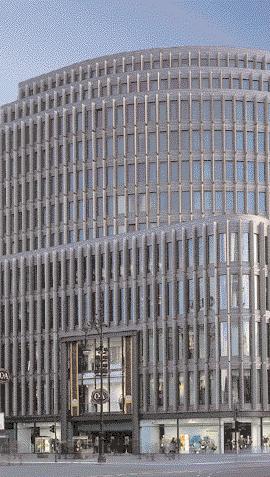
5 Situation Update While Byrnecut, in spite of problems in the shotcreting business, has managed to reach a plateau and win some major contracts, such as the Jundee-Gold project in western Australia, TMCC has had to contend with the fact that because of falling prices for raw materials clients have postponed development projects in Canada and the USA, and in some cases have even suspended current operations (for example at East Boulder mine). Efforts are also under way to extend collaboration with partners both inside and outside the TS Group with a view to winning international mining and shaftsinking contracts. In the business sector Construction Germany ongoing reorganisation and rationalisation has resulted in an improved management and control structure, better cost and performance procedures and an improved regional organisation for the two operators in this field, namely the newly formed Structural and Civil Engineering Group and our established Interior Installation Company. However, the showings of both companies have been seriously affected by the additional cost of these reorganisational measures, and even more so by the continued slump in sales and reduction in profit margins industry-wide. As well as achieving further rationalisation, and more particularly bringing improvements in indirect cost structures, the measures introduced to adapt to changing markets have focused primarily on high-value service sectors (such as DIG s heat-transfer ceilings and TS Bau s track-laying activities) and on the continued review of plant capacity and operating sites and property. Our affiliate GSES (underground stowing operations) has continued to perform well. has now established itself as a general contractor in the construction and engineering industry (for example the project for Telekom Austria s HQ in Vienna) and even more successfully in international tunnel construction (including the new Cologne- Rhine/Main intercity express line and the Plabutsch tunnel at Graz). The promising tunnel construction business is to be further expanded by way of targeted investment and collaborative ventures. In the Technology/Production sector TS Technologie + Service, which now operates as an independently-organised profit centre, has won increasing numbers of outside clients for industrial engineering and major repair projects (including work for Siemens Power Generation) and is now profitable following reorganization. Our pulverized fuel company Emscher Aufbereitung is now engaged increasingly with its major customer, ThyssenKrupp Stahl, and as a result of this growing partnership a sixth drier-crusher plant is to be commissioned by mid Our shares in the coal technology company Micro Carbon have been sold to the coproprietors (part of the RAG Group). A WORD OF THANKS TO AUTHORS AND EDITORS Once again dedicated staff members from all parts of the company have provided us with professional and informative reports on their area of work. Our established editorial team has as usual done an excellent job in selecting and processing this year s contributions and in providing our readers with an attractively-presented package. We should like to express our heartfelt thanks to all authors and editors for their contributions to this year s publication. We are confident that will again prove of great interest to all our readers and will appeal to industry professionals and laymen alike. MEETING OUR BUSINESS OBJECTIVES The past year has seen the company achieve further successes in respect of technical innovation, workforce skills and employee motivation. We have succeeded in working efficiently and in maintaining high safety standards in an organisation which is now slimmer and financially secure. In this we have never deviated from the business objectives outlined in our mission statement. We will continue to provide our domestic and overseas customers with technically innovative, high-quality solutions delivered on schedule and at competitive prices. We see our customers and associates as a vital part of our business and their prosperity is as important to us as our own. With our best wishes for the future, sincerely yours In the International Construction sector our companies in the UK and Austria have succeeded in improving their performance. While the TGB Group has been affected by falling profit margins in infrastructure building, this has been offset by higher rates of return in the specialist mining sector (including work for Scottish Coal), in the engineering sector and in insurance brokerage and financial services. The ÖSTU Group has continued to perform well and Werner Lüdtke Keith Jessup Dr. Peter M. Rudhart 3
6

7 TS MINING Mining Germany AV 8 Auguste Victoria No. 8 shaft is a symbol for the future Number 8 shaft at Auguste Victoria colliery is a downcast ventilation shaft equipped for men and materials winding. The shaft has been sunk to its final depth of 1,266 metres, which is the future mine level 7. The shaft winding system currently only extends as far as level 5. Photo left: Shaft bell inset on level 6 As the last panels on level 5 are to be worked out in 2003, winding facilities must be put in place as scheduled in early 2003 so that the shaft can connect up to the new working districts on level 6. A major part of this operation involves the construction of the shaft bell inset, the connecting entries for the north and south pass-by and the extension of the main rope winding installation. AN EARLY START In November 2000 work began on the construction of a new turnout, which had an excavated area of some 1,100 m 3 and a design weight of 37.2 t, and the connecting 216 m-long stone drift in the south pass-by zone for no.8 shaft. The roadway cross-section was reduced from 48 m 2 exiting the junction on to the 5-part BnC supports to give a crosssection of 26,9 m 2 with an arch setting interval of 0.60 m and 0.40 m of backfilling. The drivage was continued to a distance of m from the shaft centre line and then divided up into four construction sections. This was necessary both to reduce strata degradation by early support placement and to provide more favourable drivage conditions for the installation of the special support system required for the shaft landing zone, which had a maximum floor width of 11.0 m and a support height of m. Advancing the drivage for the upper structure and leaving the floor section to a height of 4.0 m above the full floor width proved 5


8 Mining Germany TS MINING Cross-section/plan view of shaft 8 pass-by Reducing the breakthrough from the south pass-by to shaft 8 of considerable benefit when it came to placing the extension supports, which had a setting interval of 0.6 m with 0.4 m of backfill, and installing the 4.0 m-long M33 grouted bolts and 2.5 m injection bolts. After completing section 3, which entailed an advance of 8.0 m to the shaft, the support system was reduced to BnC 21.0 m 2 for safety reasons and the heading driven as a ramp with a gradient of 14 degrees. Break-through into the shaft was then made as a 3.0 m-long porch-set entry with an excavated crosssection of 1.5 m 2. As the in-shaft work, including the construction of the shaft safety scaffold, had not yet been completed, the operation had to be temporarily suspended at this point. Dinting work was then needed to complete the footings and this was followed by systematic grout-bedded rockbolting with M33 x 4000 mm bolts. A ramp section was then created to again give direct access from the south pass-by to the shaft and to allow the tapering entries to be excavated in the direction of the shaft, including taking the porch-set supports in the breakthrough zone down to about 3.0 m 2. STEP BY STEP PLANNING In order to comply with various mine ventilation and safety requirements, a number of other operations then had to Brückenfeld, excavated sections to break-through into no.8 shaft 6


9 TS MINING Mining Germany be undertaken before the mining work could be completed in the shaft. This included raising the water level in the sump to below level 6, installing a pumping platform, which could be accessed by a circular ladderway, and constructing a shaft safety platform below level 5, which would divide the shaft into two separate sections. In order to meet the deadlines set for the work required in and around the shaft, the project engineers developed a working concept which essentially comprised the following phases: Erection of an in-shaft platform as a mobile working and inspection platform for the construction of the Cutting through to shaft with porch-set support system CONSTRUCTING THE SHAFT INSET Picture left: Shaft cross-section with ramp, relocated shotfiring platform The shaft inset was also constructed in sections, using a process similar to that already employed in the south pass-by and in the pit bottom area. The different working phases were pre-determined by the set levels of the shotfiring platforms from the head frame to the base frame. A combination of rock splitting and shotfiring was used to create the openings required for the 12 steel seginset. Existing installations, such as the flying cradles and small manwinding system, were to be secured or converted. Erection of steel girder structures, weighing between 3 and 30 t, to serve as shotfiring and overwind platforms in the shaft pipe and installation of shotfiring protectors to the shaft guide fittings. After the modification of the original guide-roller mountings in the northern entry point and the relocation of the rope pulley beneath the shaft safety platform, work was able to begin on the shaft inset itself. Shaft cross-section completed 7


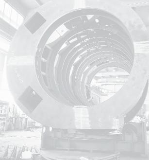
10 Mining Germany TS MINING station and altering the rope-pulley mounting beneath the shaft safety platform. end shaft 8 ments of the head frame; this involved extensive safety measures, including the installation of rockbolts and wire mesh and some strata consolidation work. After the framework had been fully installed and fixed into place the structure was backfilled with B35 concrete. This was followed by work on the two polygon steel frames and on the inner start cross-section and outer shell of the bell-inset, so that the upper structure of the south landing could be linked up to the shaft. The next phase of the operation was to move the shotfiring platform to the next level down and transfer the two hoisting winches from the north to the south pass-by. This meant constructing a new guide-roller mounting and winching AN OVERRIDING DEADLINE The project engineers have been set an absolute deadline of the turn of the year for main shaft winding to reach mine level 6. This means synchronised working around-the-clock both in the pass-by zones as well as in the bell inset. The remaining programme of work currently comprises taking a 33.0 m dint in the north pass-by to create a wider entry with footings, constructing the base frame of the bell inset together with the inner and outer shell, installing the polygon mirrors and, finally, finishing off the footings in the south landing, including complete backfilling. The excavation phase is scheduled for completion by the end of May 2002 and the subsequent dismantling work is due to finish the following month. Dipl.-Ing. Helmut Fust Dipl.-Ing. Witold Krawiec Head frame, polygon and bell inset supports 8


11 TS SHAFT SINKING AND DRILLING Mining Germany Freezing aggregate Tunnelling through frozen sand Section 3.1 of the new Fürth underground railway, which is part of the Nuremberg-Fürth railway network, traverses an area of sand acquifers, which are intended to be worked through by a process of brine freezing followed by tunnelling with shotcrete support. The 60 m-long tunnel section runs beneath a residential area protected by an architectural conservation order. The tunnel project will be carried out by a consortium led by the Munich-based contracting company Max Bögl. The contract to undertake the freezing operation has been awarded to Thyssen Schachtbau GmbH by Botec (Bodengefriertechnik GmbH) of Rastatt, and comprises the installation and operation of two twin-stage Sabroe freeze machines each producing a maximum refrigerating capacity of 465 kw. One of these machines is to be held in permanent stand-by mode as a reserve installation. The equipment started operating in February Sabroe condenser A refrigerating capacity of approximately 355 kw and transmitted temperature of around -38 C, will be provided for the freezing of this section of the tunnel. The frozen wall being maintained by a refrigerating capacity of about 175 kw. The total refrigeration requirement for the excavation of this section of tunnel is put at some 6.5 x 10⁵ MJ, while the total freeze time is estimated at approximately 3 months. Dipl.-Ing. Norbert Handke Hubert Ludwig 9

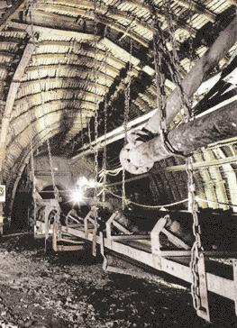
12 Mining Germany TS SHAFT SINKING AND DRILLING Controlled fall is the shortest route to the shaft The Lerche bunker has a central role to play in the coal extraction plans of the new Ost combined mine. The new freefall bunker has been constructed with a holding capacity of about 1,600 m 3 in order to provide the most efficient production link-up with the future coal panels in the Monopol district, where recoverable reserves are put at some 28 mt. The bunker has a finished diameter of 9 m and a depth of 32 m. Sinking was carried out conventionally using a 2100 mm-diameter pilot hole, with a temporary support system of rockbolts and wire mesh provided during the sinking operation. After the steel-concrete bunker chute had been constructed, the permanent bunker lining comprising a special concrete mixed with steel fibres - was installed from the bottom upwards using a resettable formwork system. A second 2100 mm-diameter borehole, which was fitted with an 1800 mm casing, was drilled close to the storage bunker to serve as a ventilation shaft. One of the project requirements was that all conveying systems had to remain operational during the construction period, as did the various supply roads and travel ways for the adjacent drivage operation. Solutions for this were devised during the project s planning and design phase. TECHNICAL INGENUITY SOLVES SPACE PROBLEM The sinking operation was being undertaken at the same time as drivage work for a connecting roadway to Haus Aden colliery. There was insufficient roadway cross-section available at the top of the bunker, where the floor width was 7.5 m and the roadway height 5.5 m. Both side-walls were widened by up to 3 m so that the excavation of the 9 m- diameter bunker could be started beneath the roadway. A number of safety measures had to be introduced at this point to protect the roadway supports and rock faces. The bunker collar was designed so that the overlying roadway supports could rest on it and on a special bridge arrangement. The logistical requirements for the roadway drivage included maintaining overhead-monorail and debris-clearance services and providing ventilation and manriding facilities. Safety guards were put in place to ensure that each workplace could operate independently of the other. The monorail track and the travel way both ran through a tunnel construction built into the bunker cover. The conveyor and ventilation ducts were relocated on a covered carrier system suspended from the roof. The manriding and materials transport systems for the bunker, on the other hand, were operated from a special platform slung beneath the bunker cover. COMPLICATED BUT FEASIBLE Both, the ventilation hole and pilot borehole were to be drilled to a diameter of 2100 mm using a Wirth HG 160 boring machine, requiring vertical clearance of 5.5 m for assembly. In order to compensate for the lack of height available and to avoid having to excavate the bunker collar from solid, a 1400 mm-diameter pilot hole was first drilled from the top road with a Turmag P1200 large-hole boring machine. A 3 m-deep collar was sunk around this, thereby creating an enlargement sufficient for the HG 160 drilling platform. The ventilation borehole was drilled at an angle of 80.1 degrees to the west. The boring machine was used to draw the casing into the hole and the annulus backfilled. 10


13 TS SHAFT SINKING AND DRILLING Mining Germany ALL GOES ACCORDING TO PLAN The sinking operation, which was carried out by drilling and shotfiring with rockbolts and wire mesh as temporary support, was completed without incident. A special cage excavator was employed for drilling the shotholes and boltholes and also for loading out the debris into the pilot hole. This machine was set up at the borehole safety cage on its own turntable mounting. The excavator jib could be fitted with a slide attachment for the various drilling operations. After the holes had been fired the drill slide was replaced with a bucket scoop, which then pushed the debris into the borehole. Mechanisation of the drilling and loading operations resulted in substantial labour savings and considerably improved the sinking performance. The bunker discharge chute, which is a steel concrete arched structure, is sited above the bottom roadway. The discharge slopes, constructed from groups of S10-profile rails, were set at an angle of 60 degrees. The cavities between the rails were filled with densit, a highstrength industrial coating which was applied in the same way as shotcrete. This material was to act as an anti-wear layer to protect the chutes from impact damage. Two discharge outlets were provided for drawing off the run-of-mine product. The bunker shaft was concreted from a special working scaffold which had been erected for the purpose. Placement of Bunker mouth with special cage excavator View of the working scaffolds during concreting 11


14 Mining Germany TS SHAFT SINKING AND DRILLING the powdered cement mortar, which contained 40 kg of steel fibres per cubic metre of concrete, was assisted by a movable formwork system made up of trussed circular sections. This 12-piece formwork was moved by means of pusher units rigidly mounted on to the working platform. After the release of two of the formwork segments, a set of three interconnected elements was engaged by the pusher units and transferred to the centre of the platform. The platform was then moved upwards so that the elements could be transferred outwards and set on top of the previous ring of forms. Only four stages were therefore required to move the formwork to its new position and link up with the existing elements. The final stage of the operation involved dismantling the safety cage at the bunker collar and assembling both the bunker intake system and the bunker outlet system beneath the discharge point. The colliery s future is now more secure thanks to this project, which was Moving the formwork to a new position completed with technical ingenuity by a team of skilled professionals. Dipl.-Ing. Siegfried Temming Dipl.-Ing. Heinrich Latos Backfilling work 12


15 TS SHAFT SINKING AND DRILLING Mining Germany Ventilation borehole doubles as coal clearance shaft Prosper-Haniel mine in Bottrop is one of DSK Deutsche Steinkohle AG s best performing collieries. The mine produces high-volatile coking coals from seams 1.40 to 1.80 m in thickness with dips varying from 0 to 18 degrees. Schematic presentation of the ventilation borehole From the colliery s main haulage level at a depth of 1,000 m the run-of-mine is brought to the surface via two inclined conveyor roads. This method of coal clearance is unique to the Ruhr coalfield. THE SHORT ROAD TO SUCCESS A new haulage way was judged necessary so that coal could be conveyed from production panel 474. For reasons of cost efficiency the colliery opted for a cased borehole that would connect roadway 4740 in seam N with roadway 4342 in seam I. The new borehole was to be fitted with both a ladderway and a 1,450 mm vertical spiral chute, which would be capable of handling a throughput of 1,700 m 3 /h thereby saving on the installation of two belt conveyors. The connecting borehole was scheduled for completion on and the contract to undertake the raiseboring work was awarded to a joint venture comprising Thyssen Schachtbau and Deilmann-Haniel. The 48 m-long borehole, which was to have a drilled diameter of 3,600 mm, was started in July The operation was carried out with a Wirth HG 250 raiseboring machine. STEEL LINING PIPE The boring operation was completed without a hitch and was followed by the installation of the steel lining, comprising a backfilled sheet-steel pipe with stiffening rings. In order to draw the lining pipe into the borehole the reaming bit at the bottom start point had to be replaced with a pipe insertion bridge. The lining pipe, complete with ladderway, was then assembled at the bottom of the borehole. Raise-bore bit After assembly, the complete lining pipe was drawn up section by section into the hole using the insertion bridge and the raise-boring machine positioned at the top of the borehole. The lining was then manoeuvred into its permanent position and the annular clearance between the pipe and the strata backfilled with hydraulicallybonded material. After the raise-boring machine had been dismantled, an auxiliary winding system comprising a drum hoist, deflection pulley and shaft cover - was erected for the installation of the K 1450/2000 spiral chute. The chute segments, which had been pre-assembled at the top level, were attached to a special harness and lowered into the hole on a carrier system that was already in place in the borehole. The remaining chute assembly work was then carried out from the ladderway. Once the in-shaft assembly work had been successfully completed on schedule, the auxiliary winding system was dismantled and the borehole cover fitted into place. On 22nd April 2002 the new haulage way was successfully put into operation. 13 Dipl.-Ing. Peter Dworzak


16 Mining Germany TS MINING Combination support system proves its worth as an all rounder An improvement in roadheading performance and efficiency is now seen as essential if the German coal industry is to reach consistently high levels of production in the years ahead. This applies especially to in-seam areas where geological conditions are difficult. A GEOLOGICAL CHALLENGE Auguste Victoria/Blumenthal colliery has for a number of years been extracting coal simultaneously from seams F and E, which are directly superimposed and only separated by a thin stone pack. Local geology has often posed problems for the excavation of the main seam roads and gate roads and for their subsequent maintenance. Roof beds which collapsed after shotfiring, short advances per round (maximum 1.6 m) and a loss of cross-section in the floor zone of as much as a metre, even during drivage, tended to be the normal pattern of events. In an attempt to counteract these phenomena a decision was taken 14


17 TS MINING Mining Germany in 1997 to increase support resistance by the systematic installation of resinbonded rockbolts. Initially the bolts were set solely using Gopher drills. In order to increase the bolting density and improve the quality of the support it was recognised that a rockbolting jumbo was the only logical move. LOGICAL DEVELOPMENT BRINGS SUCCESS On the basis of previous experience a type B combination support system was then introduced to good effect when beginning the drivage of in-seam roadway NO 35, which was the main seam road for panels 390, 391 and 392. Transition zone for overhead roofbolting: reference drivage section Roofbolting with wire-mesh lagging in heading-machine zone A high level of mechanisation was achieved through the use of the following equipment: K 313 side-discharge loader GTA type AMG 2800 platform BSR 1-LHM 357K compact drill jumbo GTA rockbolting platform hydromechanical backfilling machine. By effective application of the support installation plan and operating sequence the bolts were continuously installed at a distance of about 25 m from the heading face in a cycle of operations which was kept fully independent of the drivage operation. However, regular convergence measurements taken during the course of the drivage in seam road F/E, sub-heading 6, ultimately identified the limits of this type of support system. A new approach was required which would incorporate the advantages of the type A combination support system in the light of existing experience. The immediate installation of rockbolts at the heading face would minimize the break-up of the rock beds, while the subsequent placement of standing supports with hydromechanical backfilling would produce a roadway support system with a very high specific resistance. In the search for ways to increase the rate of advance, the question also arose as to whether, under the given geological conditions, this objective could be achieved using a roadheading machine. Certainly the experience acquired, and successes achieved, from roadheader drivages with type A combination support systems at Prosper Haniel colliery provided both reason and incentive for a similar technique to be developed at Auguste Victoria/Blumenthal (see REPORT 2001). Naturally this meant finding an answer to one important question: Is the surrounding rock in seam F/E suitable for bolting? To provide the answer, Thyssen Schachtbau were contracted in the spring of 2000 to construct a reference roadway, which involved driving a 20 m-long section of road, together with an adjoining widening, using a type A combination support system. After some minor modifications (the drill jumbo was fitted with a rockbolting and setting carriage) and an intensive programme of 15
18 Mining Germany TS MINING Rockbolting pattern reference roadway This advocated the use of 2500 mm-long steel bolts of 25 mm diameter. The resin bonded section was to be 2400 mm in length and the bolt row and bolt spacing interval 0.8 m. The rockbolting and support setting pattern was drawn up on the basis of these source data. This arrangement produced a bolting density of bolts (including the GRP units) per metre of drivage. An additional requirement was the use of tell-tale extensometers to monitor the rockbolted section of roadway. training for the drivage team, the project proved to be a complete success. This now gave the green light for planning a drivage operation using a roadheader with an on-board roofbolting and setting system. CHOICE OF MACHINE SYSTEM The following criteria and benchmark data had to be observed when selecting the machinery: 1. The excavated cross-section was 31.7 m 2, whereas the roadheader had to cut a floor width of 7.70 m and a height of 5.20 m. 2. The surrounding rock in seam F/E was very water sensitive and therefore lacking in stability. 3. The floor strata of the double seam were very soft and often streaked with coal bands. 4. The heading system had to be equipped so that it could immediately switch from a type A to a type B combination support system in the event of the drivage encountering geological faults or zones of weakness. The relatively large excavated profile was ultimately the decisive factor for the choice of a Voest Alpine AM 105 machine. In order to meet the remaining requirements the roadheader was modified as follows: 1. Fitting of an intermediate gearbox to lower the cutting speed to 1.5 m/s so as to reduce wear, allow cutting with less strata degradation and reduce the operating pressure, and consequently the volume flow, at the spray jets. 2. Incorporation of a sliding floor plate which allows the roadheader to be moved across the roadway axis without having to use the normal undercarriage. 3. Widening of the loader table to provide 7.2 m with flaps retracted and 7.80 m extended. The roadheading system comprised the following components: Voest Alpine AM 105 roadheading machine Böhler drilling and bolting rig Turbofilter dust extractor with 800 m 3 capacity GTA type AMG 2800 platform Niederholz 90 m-long drag conveyor with loading station and traction rams 1000 V pantechnicon 2 air coolers with flange-mounted duct feeder for the 1400 mm main ducting, plus combination discharge end. ROCKBOLTING PATTERN Deutsche Steinkohle s Department TB 3 prepared a rockbolting report based on a geological and geotechnical site survey. ROADHEADING BEGINS After excavation of the 200 m-long start pipe, using a type B combination support system, and assembling the roadheading machine, the drivage operation proper was able to commence in mid-december Although only a few members of the roadheading team had had long-term experience with the type A combination support system in conjunction with a roadheading machine, after a short warm-up period the rate of heading advance soon increased from an initial 5 m per working day to an average of 7.45 m. The best monthly result of m was achieved in March The machine went on to drive a total of 1,321 m of roadway, though it should be noted that at about 1,000 m the geological conditions worsened dramatically and the bolt row density had to be reduced to 0.40 m from this point onwards. A LEARNING EXPERIENCE During the drivage operation further refinements were made both to the machine system and to the working sequence so that the operating process could adapt to suit the different geological conditions. At the beginning of the drivage operation, for example, the machine was still only cutting for a single row of bolts, which were then installed immediately in order to prevent the roof beds collapsing into the cutting area. The introduction of roadhead 16
 bolting using GRP bolts made it possible to provide preliminary support for the shoulder zones and consequently to increase the")

19 TS MINING Mining Germany Bolting in the roof with compact jumbo drill. The two in-seam dirt-bands are clearly visible (reference roadway) bolting using GRP bolts made it possible to provide preliminary support for the shoulder zones and consequently to increase the repetitive cycle of cutting and bolting to 1.6 m of drivage. The use of GRP bolts at the heading face, as a function of the dip and strike of the jointing, also proved extremely effective in minimizing the quantity of large debris produced, which in turn led to an increase in the machine running time. The type of cutting and spraying system used proved not only to be the correct choice but also to be an essential requirement, given the geological conditions being encountered. The fact that the spray system produced very small quantities of water was extremely beneficial, particularly in areas affected by geological faulting. The deployment of a sliding floor plate to facilitate machine movement is also highly recommended when working in unstable ground. OUTLOOK The deployment of a roadheading machine together with a type A combination support system fulfilled all expectations. Survey measurements showed that in this drivage the loss of cross-section in the floor zone prior to coal extraction was 50% less than that recorded in comparable roadways excavated by conventional means. Work is presently under way on the start pipe needed for the installation of the AM 105 machine which will be used for driving the 1,700 m coal loader gate in seam F/E of panel 392. The drivage is scheduled to begin in mid-april. Effective collaboration at all levels, combined with the high performance achieved by the heading team, made the drivage operation a resounding success. The combination support system has certainly proved its worth as an allrounder. Dipl.-Ing. Ulrich Barth The heading team 17

20
21

22 Mining Germany TS SHAFT SINKING AND DRILLING Mechanised sinking of the Primsmulde upcast shaft sets new raise boring and shaft boring records (1,260m) The Primsmulde upcast shaft project first featured in Report 2001, which described the sinking of the extended foreshaft. This paper can now report on the subsequent sinking phases, which comprise directional drilling raise boring shaft boring and support work. I n March 2001 the Primsmulde shaft consortium was contracted by Deutsche Steinkohle AG to sink a new shaft for Ensdorf colliery. This partnership comprised mining specialists Thyssen Schachtbau, who were to act as the general coordinator for technical operations, and Deilmann-Haniel, who were to be responsible for commercial operations. The project was soon up and running and work began the following month. Directional drilling with a Wirth B 8 S rotary drill rig with mud tank DIRECTIONAL DRILLING A pilot hole was needed to serve as the clearance route for the drilling debris produced during the main shaft boring operation. This was drilled in two stages, comprising a directional drilling followed by a raise boring operation. The borehole was to have a maximum deviation from vertical, measured over the entire shaft length of 1,260 m, of half the diameter of the pilot hole (0.9 m), giving a maximum offset of 45 cm. This specification called for very high levels of drilling accuracy. The directional drilling concept devised by the engineers was designed to minimize the all too apparent operational risk, especially since the target deviation of the borehole was less than 0.1% which was not within the scope of normal measuring instruments. A special shaft cover, which would be capable of withstanding the high drilling loads, was designed for the directional drilling and raise boring operation and subsequently fitted on to the shaft collar. A fibre-glass standpipe was concreted into the bottom of the foreshaft at a depth of 90 m and then extended up through flange pipes to the shaft cover. This standpipe was to serve as a guide for the drill rods inside the extended foreshaft and would also contain the drill mud column until it reached the shaft surface. The surface drilling system basically comprised a Wirth B 8 S diesel-hydraulic rotary drill rig with a diesel-driven Triplex mud pump, which included a 40 m 3 mud tank. This expensive installation 20

23 TS SHAFT SINKING AND DRILLING Mining Germany Hole widening with a Wirth HG 330 SP raisebore rig was chosen to meet the unusually-high demands imposed when drilling a 1,260 m-long borehole. KNOW-HOW TO THE FORE After a technical and economic assessment of the directional drilling systems available from various suppliers, the choice finally fell on the Well Director 4000 vertical drilling system from DMT- Welldone. This comprised a modified, self-steering ZBE 3000 directional drilling rig of the type which has been used successfully by Thyssen Schachtbau for many years. The system provided permanent measurement of the borehole inclination above the bottom of the hole. A built-in electronics unit was used to issue steering commands to four control ribs, which were mounted externally on the non-rotating casing, so that the course of the hole could be corrected as necessary. All essential functions were designed for fully independent operation and could not be controlled from the surface. Continuous monitoring was achieved via the circulating mud in the drill string, with a pressure-pulse process being used to transfer the data to a standard PC for analysis and display. The drill tools selected for the operation were high-grade cone shaped roller bits (13 3 / 4 "), which had an average rated bit life of about 300 m. The drilling data transmitted during this demanding operation were confirmed by an intermediate survey taken using a gyro compass at a depth of 480 m. Subsequent analysis revealed a deviation of 8 cm. OUTSTANDING DRILLING PERFORMANCE A second survey was carried out at 860 m with a special magnetic measuring device which had been designed especially for this borehole. This also confirmed the previous measurement data. The vertical drilling system was removed as planned at a point 20 m before the break-through to level 20. A geophysical borehole measurement was then carried out to gauge the predicted stratigraphic sequence. In order to reduce the stresses in the borehole the hole diameter was taken down to 6 1 / 4 " and the drilling method was switched over to wire-line coring. The drilling crew finally celebrated the break-through of the directional borehole on 16th July The total borehole deviation was a mere 0.6 m. The deployment of high-quality directional drilling equipment and the precision with which the highly motivated drilling crew executed the borehole planning parameters ensured that this part of the project was brought to a successful conclusion. 21


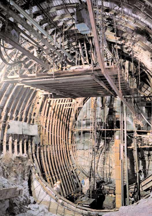
24 Mining Germany TS SHAFT SINKING AND DRILLING RAISE BORING FROM AUSTRALIA TO SOUTH AFRICA VIA PRIMSMULDE Before commencing the raise boring operation, the directional drilling equipment and standpipe were both removed and a Wirth HG 330 SP raise borer installed on the shaft cover. This machine was shipped in from Australia, where it had been operating for the Byrnecut-RUC joint venture. The electrohydraulic drilling rig had a drill thrust of 8,350 kn and a torque rating of 540 knm, making it one of the most powerful machines of its type in the world. The decision to use the Wirth borer was based on the need to run a 1,260 m long drill string, which comprised 12 7 / 8 " and 11 1 / 4 " drill rods, producing a load effort of 5,800 kn. After the 1.8 m-diameter raisebore head had been connected up to the drill string on level 20, work was able to start on the raise boring operation. The drilling debris was cleared by a slusher operating Raise boring, 1.8 m ø raisebore head, level 20 Fitting the boring head with disc cutters in tandem with a continuous conveyor. This part of the project achieved an average boring performance of 40 m a day without any significant stoppage time. After the raise boring phase had been completed the entire boring rig was packed up again into its containers and in early December everything was shipped off to South Africa for a new drilling project there. NEW SHAFT BORING 117 DAYS FROM START TO FINISH Thyssen Schachtbau have been using shaft boring technology of this kind for more than 20 years, yet this project stands out from the rest in that never before has a drilling depth of 1,170 m been achieved in a single operation. During the raise boring phase the project engineers were able to complete other tasks, including the assembly of the surface-mounted sinking equipment and the installation of the drum winder with its 450 kw drive output, which would subsequently serve as the permanent manwinding installation. Two 375 kn platform winches, a 375 kn messenger cable hoist and an 80 kn emergency travel winch were also installed in a special shaft bay to serve as supply winches. A truck-mounted crane was used to transfer the Wirth SB VII shaft boring machine to the bottom of the foreshaft at a depth of 90 m. The borer had been pre-assembled into components which were designed to be as large as possible, with individual sections weighing up to 600 kn (60 t). The machine, which had an overall weight of 3000 kn (300 t), was subsequently commissioned in January 2002 at temperatures as low as -15 C, an operation which posed a real challenge for the installation team. 22


25 TS SHAFT SINKING AND DRILLING Mining Germany lining of about 10 m of shaft per working day. SUMMARY Assembly of the Wirth SB VII shaftboring machine, mounting of the part-assembled boring head A DRILLING FACTORY WITH CONTROLLED ROTATION The boring head was driven by six electric motors each delivering 110 kw and the speed of rotation was 3.8 rpm at a drilling diameter of 8.2 m. Two sets of six stabilizer pads were used at two levels to tension the machine against the sides of the shaft. Alignment was achieved by a laser targeting system, which ensured that the drilling tolerance was kept to within a few centimetres. The support platform, which was positioned above the operator s deck, could be pivoted about 360 and featured two opposing drilling and bolting rigs for the systematic installation of rockbolts and roller mesh as protection from falling rock. A three-deck working platform, from which the support lining could be installed, followed the sinking operation at a distance of 10 to 20 m above the shaft boring machine. The lining comprised a single layer of shotcrete with B 25 grade welded steel mesh as reinforcement. The middle deck of the platform housed a material hopper with filter screen, which was supplied from the surface through a fall-pipe. A screw conveyor transferred the material from the hopper to a continuous mixing plant. An electrohydraulic concrete pump was then used to deliver the concrete to a shotcreting robot on the lower platform deck, which wet sprayed a 20 cm-thick layer on to the shaft wall. The dry material was transported by truck to the shaft and pneumatically pumped into two 50 t bins and then down the shaft via an 80 mm pipeline system with automatic control. The mechanical sinking system described above was designed for the boring and With the development of the Primsmulde workings Ensdorf colliery hopes to have new production panels up and running by the middle of the decade. The Primsmulde upcast shaft constitutes a major part of the capital being invested in the colliery s future. The project objective of minimum cost and shortest possible construction time was successfully realized by adopting a one-step-at-a-time approach. The directional drilling operation achieved a target accuracy of 0.5% and the extension hole was the deepest largediameter borehole ever drilled by the raise-boring method a significant feat of engineering by anyone s standards. The application of tried and tested shaft boring technology combined with equipment never before used in the German coal industry has produced an innovative and highly effective shaft sinking system. The Primsmulde operation will significantly enhance the international reputation of the shaft boring technique. Great credit is due to all members of the sinking crew for the dedication and commitment they displayed during the course of the project. Erhard Berger Pre-assembly of the support platform 23

26 Central Services WORK SAFETY Awarding of the BBG prize to Lohberg, Lippe and Arge Ensdorf Nordschacht collieries Trend reversal but TS still tops safety league reversal While accident figures fell steadily during the six years from 1995 to 2000, the year 2001 was marked by an increase in the number of recorded accidents. Nevertheless, our figure of 21 THYSSEN SCHACHTBAU reportable accidents notifiable industrial accidents per 1 million working hours per million shifts worked is TS Shaft Sinking and Drilling TS Technology + Service TS Mining still the best result achieved by any of the companies operating in the specialist mining sector. One of the most notable bright spots was reached on 1st February this year when the Thyssen Schachtbau team at Lippe colliery broke the two-year barrier for zero accidents at work. This result, together with various positive showings from other operating units, demonstrates how much can be and is being achieved in-house by the consistent implementation of our current action plans. The fact that the 2001 target of a 10% reduction in accidents (based on figures for the year 2000) is being retained for the year 2002 is an indication of our workforce s conviction and determination to see that the company s safety policy is successfully implemented throughout the coming year. Dipl.-Ing. Thomas Sievers 24

27 Gratulation! Zwei Jahre und verfahrene Schichten ohne meldepflichtigen Arbeitsunfall: Betriebsstelle BW Lippe Vorstand und Betriebsrat der THYSSEN SCHACHTBAU GMBH danken den Beschäftigten. Senkarbeiten Streckenauffahrung Durchbauarbeiten THYSSEN SCHACHTBAU GMBH Gerard Adamiok, Haso Alic, Ali Babaj, Norbert Baginski, Andreas Baran, Armin Baron, Resad Begic, Osman Berber, Muhammet Bilgin, Andreas Boy, Norbert Burgfeld, Hasan-Metin Cakirguen, Salih Carkic, Enes Catic, Lothar Chur, Hans-Jürgen Chwolka, Bajro Cizmic, Sefket Cokic, Serket Coskun, Refik Dadanovic, Reimund Diemann, Michael Dising, Anto Divkovic, Ismet Dizdarevic, Engelbert Dotschkal, Bernhard Duck, Georg Duck, Ramo Dzafic, Henryk Dzierzega, Karl-Heinz Emmerich, Werner Engel, Kadir Erdioglu, Norbert Franik, Stanislaw Frojn, Edhelm Gaca, Stanislaus Gajewski, Jean Gans, Peter Gebele, Georg Geißler, Joachim Gersch, Ralph Gerstenberger, Bernhard Göhr, Mehmet Gök, Triso Gordeljevic, Peter Gwozdz, Bahrija Hadrovic, Hans-Günter Heinschke, Helge Herber, Sasa Hvala, Wolfgang Ickert, Mevluet Izbudak, Leonhard Jacobs, Eduard Janczewski, Johann Juland, Ibrahim Kabasakal, Helmut Kalweit, Roman Kaminski, Rufad Karabeg, Resid Karic, Georg Paul Karkos, Miroljub Kasic, Mustafa Kaya, Frank Kazmierczak, Engelbert Kellermann, Johann Kempinski, Andreas Kisiel, Rolf Kleisa, Bernd Kliche, Norbert Klossak, Hans-Dieter Koch, Klaus Konen, Ulrich Kotecki, Stefan Kotz, Adam Kowoll, Arkadiusz Kowoll, Maid Kozlc, Frank Kristofics, Jürgen Krucinski, Jörg Krzewina, Günther Kube, Janozs Kubis, Waldemar Kubitza, Markus Kurpick, Jörg Kutsche, Eugen Kwasniok, Branko Ladan, Harald Lauf, Jozef Lautner, Siegurd Lettau, Volker Liese, Manfred Lipok, Theodor Luc, Thomas Marcinkowski, Hubert Marocke, Dieter Meiworm, Lothar Melerski, Bogdan Michael, Radovan Milakovic, Manfred Möller, Paul Morawiec, Aljo Muhtarevic, Fadil Neimarlija, Bernhard Nickel, Izudin Nuhanovic, Wladimir Oborotow, Ayhan Oikenli, Joerg Olthof, Nihat Özarslan, Selmani Özyurt, Michael Peters, Drago Petricevic, Gerhard Ploch, Christian Przybylla, Joachim Pschibilko, Kurt Repaschewsky, Helga Riese, Manfred Rölke, Joerg Roth, Wolfgang Rühl, Reha Samur, Ahmet Sari, Nevres Saric, Siegfried Schaletzki, Udo Schlieper, Uwe Schlotter, Georg Schwieder, Karl Sebbel, Muharem Siocic, Jan Skubacz, Saum Soytay, Herbert Spannhacke, Markus Stach, Michael Starklauf, Andrzej Starzyk, Josef Stegemann, Hans-Jürgen Steingens, Michael Subert, Norbert Südmeyer, Josef Szczesny, Slavoljub Terzig, Reuf Tinjic, Uwe Treptow, Ayan Türkili, Halil-Ibrahim Tutar, Edwin Uebernickel, Walter Urban, Peter Wagner, Detlef Wegmann, Siegfried Werner, Josef Wieczorek, Henryk Witasik, Thomas Woschek, Axel Wüller, Yasar Ruhrstraße 1. D Mülheim an der Ruhr Tel.: **49/208/ Fax: **49/208/ Yilmaz, Wolfram Zander, Richard Zlocki

28 Surface installations in winter with condensation smoke from upcast shaft McArthur River Year 9, Ongoing Infrastructure Development In June 2001, Thyssen Mining Construction of Canada (TMCC) mobilized to McArthur River in northern Saskatchewan in continuation of developing the underground for future production. After a 5-month spell with no development works, TMCC and Joint venture partner, Mudjatik Enterprises, were contracted to provide both mining and construction services to meet present and future mining production requirements of the McArthur River underground Uranium Mine. SCOPE OF WORK Mudjatik Thyssen Mining (MTM) is involved in work activities such as: probe hole drilling and pressure grouting ahead of development; excavation of tramming drifts, ramps and ore extraction chambers; installation of ground support including shotcrete; concrete placement on sills and backs; backfilling extraction chambers with concrete and rock fill; and other civil and mining work necessary for ongoing operations. Most of the work performed by MTM includes accessing the raiseborer locations above ore zones and setting up the production chambers below ore zones. Sizes of drifts excavated range from 3 m x 3 m to 6 m x 6,5 m. MANPOWER AND SUPERVISION There are four mining crews working at McArthur River on a shift rotation schedule of 2 weeks in and 2 weeks out. Access to the mine site is by planes flying four days of the week. Saskatoon and Prince Albert, Saskatchewan are the principal points of hire, but over 58 % of the workers reside in northern Saskatchewan. MTM has been able to draw from a previously trained labour pool to fill many positions at this site. The Resident of Saskatchewan North (RSN) labour pool come from such places as La Ronge, Black Lake, Stoney Rapids, Uranium City, Fond du Lac, lle-a-la-crosse, Patuanak, Green Lake, Cumberland House, Turner Lake, Buffalo Narrows and La Loche. The nature of the work calls for the mining crews to be versatile in their abilities and to be flexible in their work priorities. Each mining crew consists of a leader, four miners, and one construction miner. Maintenance of contractor equipment is performed by a crew of 3 mechanics per day. Both mining and mechanical crews work two 12-hour shifts per day on the two week rotation. Supervision on site is conducted by one Superintendent aided by the site clerk. The Superintendent is responsible for overseeing the work and directing the crews according to the daily operation requirements. Night shift work is lined up by the Superintendent and supervision is performed by the client. 26


29 TMCC Mining International Biweekly planning and scheduling meetings are held with the client to review the future work plans and provide time to adjust manpower according to the current activity levels. EQUIPMENT FLEET There are two main levels at McArthur River, the 530mL and the 640mL. These two levels are connected with an internal ramp system and thus only one set of mining equipment is required. Equipment is transferred between the levels and sublevels according to the specific tasks the crews are undertaking. For the performance of this contract, MTM has the following equipment on site: 2-boom E/H Jumbo Single-boom Bolting Jumbo Scissor Lift Platform 3-yd LHD Scooptram 6-yd LHD Scooptram Concrete Pump Wet Shotcrete Sprayer with Remote Boom Drill jumbo engaged in setting 4.8-metre resin-grouted bolts Jacklegs & Stopers Grout Pump & Mixer Face Pumps GROUND SUPPORT All excavations require standard ground support measures, which include resin bolts, split set bolts and wire mesh. This standard calls for full screening of the back and walls to 1.2 m from the sill. Bolting is laid out on a 1.2 m x 1.2 m Haulage road alongride dismantled and filled roadway 27


30 Mining International TMCC pattern and all installed are 2.4 m resin grouted with the exception of the first two rows up from the sill, which are 1.8 m split sets. Poor ground conditions warrant the application of spiling, cable bolts and/or shotcrete as an additional means of support. SHOTCRETING The application of shotcrete is a very important function at the McArthur River mine site. It is not only used as a means of ground support, it acts as an excellent material for shielding against exposure to gamma radiation. As part of our contract calls for excavating through low to high grade ore zones, MTM must use shotcreting techniques to limit the amount of exposure introduced to our mining crews. Specifically for this contract, MTM has aquired a Driftech MSV 2100 remote shotcrete sprayer to apply wet shotcrete to the back and walls when we are excavating through such ore zones. The faces of drift rounds through ore zones must also be shotcreted to shield the miners when they are charging them with explosives. The operators of the shotcrete jumbo must stand a minimum of 8 m from the source of radiation and this unit has a line-of-site remote controller to allow this to take place. Although shotcreting is nothing new to our operation at McArthur River, MTM has retained the services of a shotcrete trainer to instruct our crews how to apply wet shotcrete effectively and The new mobile MSV 2100 E Shotcrete Sprayer during maintenance Completion of raisebore drill chamber using shotcrete, concrete floor efficiently with this new unit, with and without the remote. The MSV 2100 Shotcrete Sprayer is a state-of-the-art shotcrete application unit that houses its own concrete pump and air compressor for faster set-up times. Similar to a drifting jumbo, it is driven to the shotcrete area under diesel power and then hooked to a 600 volt power source for shotcreting. Four stabilizing jacks help hold the unit steady for smooth shotcrete operation. The boom has an oscillating actuator attached at the head to rotate the nozzle as it moves forward and backward while spraying. In the shotcreting mode, the boom also has a lancing feature that extends and retracts automatically. Lateral boom movement is performed by the operator as well as the nozzle direction, which allows for shotcrete placement in hard-to-reach places and for shooting around corners. It is possible to apply shotcrete to a 2.4 m section of drift from one set-up. Access ramp to raisebore drill chambers with shotcrete fillings and concrete floor ACCOMPLISHMENTS The contracted lateral development stands at 65 % complete in 35 % of the contract time of 20 months. Slashing and filling of extraction chambers and raisebore drill chambers is dependent on availability. To date, one of four 640 level extraction drifts has been slashed and filled while the others are still being mined. On 530 level, we have just begun filling the first of two raisebore chambers and are anticipating starting to slash soon. Along with the mining activities, MTM has completed other civil work. On

31 TMCC Mining International level, we changed 125 m of the main ventilation ducting. Two six-metre sections of worn concrete/shotcrete slick line were changed in the bottom of Shaft 2 where access was by staging, constructed inside the shaft especially for the purpose. Miscellaneous concrete pours have been completed on 530, 560 and 640 levels amounting to 622 m 3. The 7275E extraction chamber on 640 level required pouring concrete on the back remaining 3 extraction drifts on 640 level will complete the excavation planned for The remaining planned work, preceding the production drift slashing on both 530 and 640 levels, will be the construction of the fill bulkheads of existing chambers. There are discussions of adding over 400 m of drifting on 580 sublevel to the present contract for completion this year. Choice at McArthur River as we maintain a presence at this mine site into the new millennium. JD Smith Haulage road on 640-metre level close to filled roadway and lowering it 1.5 m to allow access for attaching and removing the reamer. Since the beginning of the project, MTM has placed 1,004 m 3 of shotcrete pre Driftech. FUTURE PLANS As part of the original contract, development of the 530 level Panel 5 raisebore chamber will complete the planned drifting on this level. Other 530 level excavations will be performed by slashing means to set up 3 new raisebore chambers. On 640 level, drifting will be completed with the final 30 m in the coarse ore storage. Slashing of the SITE SAFETY MTM employees are conscientious about safety in the performance of their work, abiding by all the standards and procedures in place. Daily as well as weekly safety meetings are held to discuss any issues that are of concern for the current or upcoming work. From project conception, MTM has experienced 5 minor first aids and 1 medical aid. In December 2001, the MTM site achieved a six-month milestone with no Lost Time Accidents (LTA). This being a continuation of contracts, MTM has the title of Contractor of 29

32 Mining International TS SHAFT SINKING AND DRILLING Constructing underground sealings and dams in the Potash and Rock-Salt Industry Dammbauund Abdichtungstechniken The Thyssen Schachtbau Group has over many years acquired extensive experience in the construction of sealings and dams for the potash and rock-salt industry. Projects such as those at Rocanville (Saskatchewan, Canada), Hope, Gorleben, Sondershausen (construction of the Immenrode and EU-1 dams) and Merkers called for design, construction and injection technology which reflected the Company s broad range of technical abilities and know-how. The experience acquired and the techniques developed along the way will certainly stand the Company in good stead when designing and carrying out projects of a similar kind, such as the sealing of permanent waste disposal sites and the erection of long-term seals and plugs. Specific criteria have now been developed for assessing the construction, design, function and efficiency of such structures. DAMS Dams in the form of long-term roadway seals or plugs are designed to seal-off operational mine workings in order to prevent the ingress of mine water and gas. Dams operate in conjunction with the surrounding strata both to act as a seal and to serve as an abutment against pressurized liquid or gaseous media. Roadway seals and dams can be used to create a long-term barrier between a risk-prone area and a part of the mine which is not threatened by inflow. Such structures are generally put in place during the construction phase or installed subsequently in the pack/strata contact zone, though they can also be injected directly into the pack material. In addition to the potash and rock-salt industries, underground waste tips and colliery-based permanent disposal sites also employ long-term seals and dams for safety reasons. In comparison with the dams constructed in the potash and salt mine industry, however, the wastedisposal industry often requires such structures to retain their sealing properties over an extremely long period of time. The construction technology employed for constructing seals and dams in underground storage dumps and permanent waste disposal sites is basically similar to that normally used in potash and salt mine industry. The similarity between the two techniques is most pronounced when as in the case of the Hope project the requirement is merely to reduce the potential recirculation of mine waters and solutions through the workings in the long term, rather than to provide a permanent seal against such ingress. INJECTION MEASURES USED IN COMBINATION WITH STRUCTURAL SEALS Injection sealing is now the accepted practice for averting and controlling hydrological hazards. When used in conjunction with underground packs and dams, the injection technique considerably increases the sealing capacity, interlock strength and operating life of the construction. The most recent large-scale use of injection methods in saliniferous strata was during the sinking of the Gorleben 1 and 2 freeze-shafts for the DBE explor- 30

33 TS SHAFT SINKING AND DRILLING Mining International ation mine (DBE is the Peine-based company responsible for the construction and operation of toxic-waste storage sites), where this technique was successfully employed when traversing the so-called contraction fissure zone. The operation involved the application of drilling and sealing techniques, using magnesia binders and Sorel s cement, to seal the salt-plug surface and caprock zones. The drilling and injection work, on which the success of any injection sealing operation depends, must be carried out to a very high standard. This naturally also applies to the quality of the construction and sealing materials. PRACTICAL EXAMPLES When assessing and designing the structure and formation of underground seals and dams it is advisable to examine existing seals and barriers which have been successfully installed in saliniferous strata. The Rocanville dam In 1984 the Canadian potash mine of Rocanville, which is owned by the Potash Corporation of Saskatchewan (PCS), encountered a brine-salt deposit in a roadway drivage being excavated at a depth of some 975 m. The deposit in question was being fed from the overlying roof strata and the inflow, which comprised both salt solution and gas (H2S), initially amounted to about 3m 3 /min, though subsequently increased to peak at between 14 and 20 m 3 /min. A structural dam, measuring 7 m by 2.7 m in cross-section and about 28 m in length, was designed by PCS and installed together with TMCC within a period of about 2.5 months. The materials used were magnesia cement with silicate aggregate and bentonite. The dam was constructed in two parts, which were separated by two sealing chambers filled with a Dowell Chemical Seal Ring. After the dam was constructed injections were applied throughout the entire cross-section of the structure, concentrating particularly on the annulus between the pack and the strata, in order to create an effective seal. The structural barrier, when installed in conjunction with drilling and injection work, produced a successful seal. In spite of the fact that the 76 m-long structure (length of dam plus length of frontal embankment) had to be constructed as a matter of extreme urgency, with the area under constant brine ingress, the project was successfully completed to specification. The barrier is still operating effectively at a static gauge pressure of 98 bar. Gorleben shafts: contraction fissure zone When using the freeze-shaft sinking technique the cooling of the strata Drilling of horizontal injection boreholes 31


34 Mining International TS SHAFT SINKING AND DRILLING produces tensile stresses which result in fissuration and create a finely-branched network of joints, fractures and pores which is referred to as the contraction fissure zone. When sinking Gorleben shafts 1 and 2 of DBE the maximum temperature difference recorded when using the deep-freezing process was about 66 C, with an initial temperature level of some 26 C. This large difference in temperature during the rock cooling phase, combined with an extremely long freeze time, led to an extended and finely-branched contraction fissure zone. To ensure safe and trouble free sinking through this zone, which lay between the 260 m and 320 m levels, it was first essential to employ a systematic pre-drilling programme, involving coredrilling and inflow metering, to determine the fissuration characteristics and flow rates, so that targeted injection sealing could be carried out on the basis of this information. The injection material was a mixture of magnesium oxide, magnesium chloride and brine solution. The preliminary drilling and injection programme involved drilling boreholes of up to 75 m in length, some of which were rebored several times prior to injection. For the sealing of the contraction fissure zone in Gorleben no. 1 shaft a series of cluster holes and screen holes was drilled at different angles (about 850 different drill-holes making a total hole length of some 35,500 m), and a similar operation was undertaken in the second shaft (about 700 different drillings giving a total hole length of 28,600 m). Each individual hole was redrilled and injected on average 2 or 3 times until a complete seal was achieved and verified. Construction of the roadway dam EU1 The EU-1 full-scale experimental roadway dam 32
 in 1982, was subsequently flooded with brine.")


35 TS SHAFT SINKING AND DRILLING Mining International The Hope dam: installing the inner asphalt-sand seal Schematic diagram of the Hope potash mine dam (1983/1984) Bringing in of high-compacted bentonite blocks The Hope dam The Hope potash mine, which was shut down by its owners (Kali und Salz GmbH) in 1982, was subsequently flooded with brine. A research and development project was drawn up to investigate and record the geochemical, geomechanical and geophysical processes involved both during and after the flooding of the mine. The management and scientific control of the project was entrusted to the Institute of Underground Disposal, which is part of GSF (Gesellschaft für Strahlen- und Umweltforschung mbh a radiation and environment research company), while Kavernen Bau- und Betriebsgesellschaft (KBB) was to be responsible for the technical and administrative aspects of the operation. The R & D programme included a project to erect and assess a permanent dam which would involve testing new materials and techniques at pressures of up to 2.5 MPa. The design calculations were based on a hydrostatic pressure of 6 Mpa and the structure was successfully designed, built and fitted with instruments within a period of one year. The dam was constructed for KBB as a roadway or chamber seal and was set up in a horizontal dead-end roadway at the 500 m level. Absolute watertightness was not required and the dam was designed to act as a flow barrier. The structure consisted of 2 abutment/ support sections in saline concrete, each 5 m in length, which featured a 50 cmthick asphalt joint to act as a stabilized internal seal. On the water-facing side the dam featured a 25 cm-thick frontal seal which comprised five alternating layers of bitumen and corrugated stainless-steel plate. This seal served to protect the surface of the stopping from leaching and chemical attack. To install the abutment structure in the form of a simple prismatoid the existing roadway cross-section had to be carefully widened from 8 m 2 to 26.5 m 2 at its front face so that it formed a wedge shape which tapered towards the air intake side. To prevent any bypass effect the internal and frontal seals were each set into a 30 cm-deep channel. Flooding of the potash mine commenced in March In early 1988 the seal was exposed to a fluid pressure of 2.2 Mpa. This was somewhat less than half the figure for which it had been designed. At the time the data transmission system was switched off in May 1988 there were no signs of any brine solution having penetrated the structure. The Springen support packs at Merkers mine The Springen support packs are part of the conservation concept for Merkers mine, which is operated by Kali und Salz GmbH, and are designed to provide longterm roof support for the Springen district. Absolute watertightness is not required. The packs were considered necessary because partial bed separation and spalling had been occurring repeatedly within the existing roof beds of the brown-red saliferous clay phenomena which presented the latent risk of a large-scale roof collapse and which in turn could have resulted in a failure of the geological barrier protecting the workings from the water-bearing strata. The support packs to be constructed in the former development roadways totalled 216 m in length, with an average roadway profile of 30 m 2 (cf. Report 1999). A powdered limestone product was used as the pack filling material. For logistical reasons the pack material 33


36 Mining International TS SHAFT SINKING AND DRILLING was mixed at Springen no. 1 shaft bank and then pumped to the placement site. After mixing, the free-flowing material was transferred to a shaft fall-pipe and pumped to the site via a horizontal district pipeline installed on no. 1 level. The total pipeline length was approximately 1,600 m. The equipment and materials used, in conjunction with the high-performance mixing and pumping plant, have proved very effective for the construction of packs of this type. The Immenrode dam The geological barrier between the former Sondershausen rock-salt mines and the adjacent Ludwigshall/Immenrode mine, which was in the course of being flooded, was provided with a longterm reinforcement during 1998 and 1999 in the form of a geotechnical barrier, which was installed in the salt strata in a 3 m-diameter circular connecting roadway at a depth of some 700 m (see Report 1999). The geotechnical barrier, which took the form of a horizontal cross-section seal, consisted of a short-term seal for immediate effect and a long-term seal, which The Hope dam, longitudinal section was to come into play as convergence pressures built up (Fig. 5). The sealing system chosen by the Erfurtbased company Ercosplan Ingenieurgesellschaft Geotechnik und Bergbau mbh in agreement with the Ingenieurpartnerschaft für Bergbau, Wasser- und Deponietechnik (IbeWa/Freiburg) comprises a symmetrical roadway barrier which is capable of withstanding loading from any direction and is designed to remain fully operational in the very long term. The long-term dam installed in the circular-section roadway consists of a 10 m-long core seal and two external sections each about 8.5 m in length. On the basis of research work carried out at the Mining Institute of the Freiberg University Academy of Mines it was decided for the first time to employ a sealing material designed for long-term stability, namely high-compacted, dryerected bentonite blocks (Fig. 6) of different grades and geometry which Drilling of vertical injection boreholes, Gorleben Freeze Shaft 34

37 TS SHAFT SINKING AND DRILLING Mining International Overall view of finished abutment and sealing contours of the EU-1 roadway dam were installed in conjunction with specially graded sand. This long-term roadway stopping acts both as a seal and as a load-bearing structure. The EU-1 roadway dam Contractors working on behalf of the Freiberg University Academy of Mines, and using the latter s own design, constructed an experimental dam in roadway EU-1 at the Glückauf Sondershausen mine in 1999 (see Report 2000). The structure was installed at a depth of some 700 m in a dead-end roadway which originally had a circular profile of 3 m diameter and the contours of the sealing element and abutment were created using a cable-saw system, which was designed for minimal rock degradation. The design called for the circular profile of the excavated diameter to be opened out to create a rectangular cross-section measuring 3.5 by 3.2 m which would be capable of accommodating the 5 m-long seal and 3.5 m-long prismatoid-shaped abutment. Viewed from the pressure side of the dam, the structure comprises a pressure chamber, main sealing element (compressionmoulded bentonite blocks), control chamber with mastic asphalt seal and static abutment built from compressed saline blocks in a dry-wall construction. The experiment resulted in a brine-pressure build-up of 80 bar. The dismantling work currently under way on the experimental dam is expected to provide valuable and precise data on its sealing function and effectiveness, as well as on brine propagation and the stress levels acting on the structure. Sealing the Gorleben freeze-holes for long-term stability The freeze pipes for Gorleben shafts 1 and 2 of DBE are now being withdrawn and the freeze holes closed to produce a watertight and stable seal in order to recreate the barrier effect of the saliniferous strata and overburden. Special drilling, cutting and extraction equipment is used to withdraw and dismantle the freeze pipes and protective casings, which have been deformed by the action of the freezing process and shaft sinking operation. Suitable sealing and injection methods are then to be employed to close the freeze holes, which includes the use of a special grade of cement to produce a long-term seal, in accordance with the local geological conditions. ASSESSMENT OF AVAILABLE SEALING TECHNOLOGY The experiences of the potash mining industry, both in Germany and in other countries, show that the possibilities for sealing-off inflows in salt rock are limited and no particular method can fulfill all the requirements. The projects undertaken at Rocanville, Hope, Gorleben and Sondershausen demonstrate, however, that full-section dams and injection seals are capable of providing an effective seal against inflows and that such structures are technically feasible. The sealing operations outlined above, however, constitute special solutions which are designed to meet individual requirements. Provided that suitable sites are available, injection seals applied in combination with dams offer the best prospects of achieving a 100 %-effective seal. The approach adopted at Hope mine seems to be a promising solution to the problem of reducing potential brine and gas circulation through the underground workings in the long term; however, the applicability of this technique still has to be established in each individual case. This type of cross-section seal acts as a flow barrier and absolute gas- and water-tightness is not required. Dams which are of sufficient length are capable of compensating for local irregularities and defects, both in the structure of the dam itself as well as in the ring-joint and surrounding strata. Underground packs, roadway dams and shaft seals are characterized by a number of special features which have to be taken into account during the design and construction phase. The structures themselves basically have to be installed in retreat workings, which means that after erection there is little opportunity to carry out maintenance and repair work or to check the functions of the different components. As a result, such structures have to meet very high specifications in terms of design, construction and quality control. FUTURE DEVELOPMENTS The Mining Institute of the Freiberg University Academy of Mines has for many years been closely involved in the construction of sealings and dams for the salt and potash industry. Collaborative projects for the erection of long-term underground sealings are now to be developed and implemented not only in Germany but increasingly at international level. One example of this type of venture is that being proposed in Canada, which is to be undertaken in conjunction with the TMCC. 35 Dipl.-Ing. Norbert Handke
 Group was established in June 2000 after purchase of the assets of a well-known drilling company which had gone into liquidation.")
38 Mining International TGB TRENCHLESS TECHNOLOGY THYSSEN THYSSEN TRENCHLESS TECHNOLOGY Thyssen Trenchless Technology (TTT) the latest addition to the activities of the Mining Division of the Thyssen (Great Britain) Group was established in June 2000 after purchase of the assets of a well-known drilling company which had gone into liquidation. Since formation TTT has invested some 1million in horizontal directional drilling equipment giving it a range of units from 12.5t up to 70t pullback capacity. The fleet includes an ADDS/Wirth Powerbore 70/15 drilling rig, two Vermeer D24 x 40 rigs and a D33 x 44 system. The section also has a range of pit launched rigs that have been developed from some of the mining systems. These rigs can install pipes of up to 1m diameter and up to 1000m in length. Helped by Thyssen s experience in drilling techniques for over 40 years, Thyssen Trenchless Technology has been able to establish itself as a competent and experienced horizontal directional drilling contractor over a relatively short period of time. Since inception in June 2000 TTT has carried out in excess of 100 drills ranging from 10,000 to 100,000 in value. A typical contract was the crossing of the river Tweed at Coldstream, a small town situated on the borders of England and Scotland. The contract awarded by Nacap Telecom UK called for a 166m crossing with a 250mm sleeve pipe, including ten 40mm ducts for fibre optic cables within its sleeve. SITE INVESTIGATION Prior to the work commencing ground investigation was undertaken with two 25mm diameter vertical boreholes being drilled to the top of the sandstone bedrock level. These boreholes gave limited information but indicated that the drilling contractor would encounter gravels, some including cobbles and possibly some soft sandstone (although no compressive strength could be established). Environmental concerns were also expressed by SEPA (The Scottish Environmental Protection Agency), Nacap and the River Authority. The concerns were based on the fact that any pollution of the river from use of directional drilling techniques would affect the lucrative fishing industry (salmon especially). Charges of up to 5,000/week are made, for rights to fish a stretch of the river. 36


39 TGB TRENCHLESS TECHNOLOGY Bergbau Mining Location of the crossing underneath a bend of the river Tweed To counter these concerns, stringent environmental protection prerequisites were imposed on the site including a zero spillage policy from the bore and bore site. The operations were also to stay within SEPA s general guidelines throughout. CROSSING Work started on the site on 12 August 2001, with a view to completing the installation, including the duct installa- tion, in about 10 days, however, whatever the circumstances the project programme dictated that completion had to be by the end of August. The bore plan was to start from surface, drill through the gravels to a depth of 8m, which would take the bore into the sandstone horizon. Then the bore would continue horizontally for the width of the river crossing in sandstone and finally rise back through the gravels on the far side of the river to holing. TTT decided to utilise their new ADDS/Wirth Powerbore 70/15 drilling rig ( 70 indicating pullback tonnage capacity/15 indicating drill rod length), Thyssen s new APPS Powerbore 70/15 at the construction site 37

40 Mining International TGB which can develop up to 22,700 ftlb of torque. The choice of machine proved wise given the ground conditions encountered. Guidance was provided using a DigiTrak walkover system. On the river crossing section of the bore, the system s look forward facility was utilised to maintain the bore route. Gravels are notorious for the problems they bring to directional drilling works. On this project, TTT utilised a water and gum mix through the gravel horizon to maintain ground control and support. The drilling fluid was not only able to keep the hole open but also to transport cobbles from within the bore of up to 100mm diameter. On passing into the sandstone horizon the drilling fluid was changed to a light bentonite mix, with the gum mix being used on the exit side of the bore, again through the gravels. PILOT BORE Utilising a 125mm diameter mud motor and a 160mm diameter TCI Tricone drill bit, the first part of the pilot bore ran through the dense gravels as previously mentioned. Due to the very dense nature of the gravels and the cobbles encountered, a lot of drilling fluid was pumped into the ground to maintain hole stability. This, and the very careful advance that was required by the rig operator, meant the first section of the bore to the sandstone horizon took some 31/2 days. Advance rates through the sandstone proved slow as the rock horizon was found to be much harder than indicated in the ground investigation reports. The average advance for the river crossing section through the sandstone was as low as 30 minutes per drill rod. On the exit side, the run back through the gravels was not as arduous as that on the entry side, as much had been 38 The APPS 70/15 during borehole widening operation learnt about the mud required to support the gravels. The six drill rods that were needed to exit the bore on the reception side took just 4 hours to complete giving a total pilot bore run of 5 full days. To open the pilot bore to the size required for the casing pipe installation a 325mm diameter TCI 4-cone rock reamer was utilised to complete the upsize in a single reaming run. This was done in just 11/2 days. This was followed by a bore cleaning run using a 325mm diameter barrel/compacting reamer. This same reaming head was utilised as the lead-in for the pullback of the casing pipe. The 250mm diameter MDPE SDR11 casing pipe was supplied in 6m and 12m lengths, which was butt fusion welded on site. THE FUTURE Based on its experience and the plans to make further investments in new and larger capacity horizontal directional drilling equipment Thyssen Trenchless Technology is confident of becoming one of the UK s leading Trenchless contractors. Kurt Klingbeil


41 TS SHAFT SINKING AND DRILLING Mining International After a lengthy process of tendering and negotiation which lasted more than a year, all the effort put into the bid for the Sedrun II shaft sinking project in Switzerland has finally paid off. The contract to sink the 800 m-deep Sedrun II shaft was finally awarded to the consortium of Thyssen Schachtbau GmbH, who were to be in overall charge of the project, together with South African partner RUC International Ltd. and Austrian affiliate Östu-Stettin Hochund Tiefbau GmbH. This shaft is part of the Sedrun intermediate stage, an operation which is designed to open up a 6.2 km-long section of the Gotthard main tunnel which is currently under construction. The main tunnel excavation is to be serviced via two shafts. The first of these, Sedrun I, has already been sunk and is currently being equipped with a high-performance shaft winding system. The collaring points for both shafts are approximately 1,350 m above sea level. Sedrun valley cut with portal for access drift Thyssen Schachtbau at the Gotthard! Sinking the Sedrun II shaft for the world s longest tunnel NEW CROSSING FOR THE SWISS ALPS The Gotthard main tunnel, which will form part of the European integrated rail transport network, will comprise two single-track tunnel pipes each 57 km in length and will be by far the largest construction operation within the Alp Transit Project. When it is completed in 2012 the Gotthard crossing will be the longest road tunnel in the world. The main contractor for the Sedrun II shaft sinking is the joint venture group Transco-Sedrun. This consortium, which is led by the Swiss construction company Batigroup AG, has been contracted by Alp-Transit Gotthard AG to construct the section known as the Sedrun tunnel. This section forms the centre-piece of the Swiss Alpine crossing and is the most technically and geologically challenging part of the entire tunnel route. RODLESS SHAFT BORING WITH PILOT HOLE After a technical evaluation of the bids, the contract was finally awarded to the Thyssen Schachtbau consortium on the strength of its proposal to use a special rodless shaft boring system with a pilot hole drilling. After taking into account the local geology, which consisted of a steeply-inclined sandwich-type sequence of beds comprising both hard and soft strata, this system was judged to be the most suitable and least-risky of all the sinking methods being proposed. The 1.8 m-diameter pilot hole for the Sedrun II shaft was to be drilled as a raisebore hole using a type HG 330-SP Wirth raiseboring machine. A Wirth VSB VI shaft borer would then be brought in to bore out the shaft to a diameter of 7.0 m with minimum strata degradation. At the Sedrun site the main tunnel level was first reached in February 2000 via a 1 km-long access drift and the 800 m- deep Sedrun I shaft. The Sedrun II shaft is a key part of the preparations for the start of the main tunnel construction work in that during the main tunnelling phase this shaft will serve as an air exit and access shaft for the transport of heavy plant and building materials to and from the tunnel face. Dipl.-Ing. Norbert Handke Erhard Berger 39
 was awarded a contract for the excavation of hydroelectric tunnels near Revelstoke in the province of British Columbia. The owners of the project, Canadian Hydro Developers (BC) Inc.")

42 Mining International TMCC Pingston Creek HYDROELECTRIC PROJECT Pingston Valley (winter 2000) In mid March 2001 Thyssen Mining Construction of Canada Ltd. (TMCC) was awarded a contract for the excavation of hydroelectric tunnels near Revelstoke in the province of British Columbia. The owners of the project, Canadian Hydro Developers (BC) Inc. and Great Lakes Power Ltd., planned the project as a 30 MW power generation facility with minimum environmental impact. Canadian Projects Ltd., based in Calgary, Alberta, are the project managers. The tunnels are intended to convey water from Pingston Creek, at an upper elevation of approximately 1,038 metres to a lower elevation of 535 metres, and ultimately to a Pelton Wheel driven generator located adjacent to Upper Arrow Lake. To achieve this 3,560 metres of tunnel consisting of 2,130 metres in an upper tunnel, and 1,430 metres in a lower tunnel will be excavated. The two tunnels will be connected with a 465 metre raisebore hole. Main considerations in TMCC s proposal were: Logistics of operating three tunnels concurrently approximately 45 minutes travel between the three tunnels. Logistics of the location 70 km from Revelstoke including 12 km of logging roads. Winter weather substantial snowfall can be expected. Sourcing the correct equipment. Obtaining a workforce with the necessary skills. Expected mining conditions. Three areas of attack were available, two on the upper tunnel (east and west) and one on the lower tunnel (east). Because of the distances involved and the constraints associated with diesel equipment, as well as support considerations, TMCC s proposal was based on minimum excavation sizes using primarily a combination of tracked air and electric equipment. However, because access to the inlet portal was expected to be restricted in the winter, and in order to achieve the owners schedule, approximately 570 metres of trackless development was planned from the upper west tunnel. The 1,560 metre balance of the upper tunnel, and the 1,430 metres of the lower tunnel will be mined from the east using tracked equipment. Stripping Upper West Portal (spring 2001) 40
 x 3.")


43 TMCC Bergbau Mining Upper East Portal (winter 2001) Collaring Upper West Portal (spring 2001) Nominal tunnel dimensions were planned to be 2.4 m (w) x 2.7 m (h). This size was considered the minimum required for the Hag cars and overshot loaders used in the mucking operation. Final dimensions are closer to 2.7 m (w) x 3.0 m (h) as the additional muck generated by the larger size was more than offset by operational and safety improvements. The connecting raise is currently planned to be a 1.8 m unlined bored hole. This is presently being reviewed by the owners. Face drilling was initially planned to use exclusively hand held jackleg drills. Long Tom rail mounted twin boom jumbos, which are operated manually and use the same drills as the jacklegs, were introduced during the course of the project. These have improved drilling time and accuracy. A combination of jacklegs and stopers is used for bolting. Ground conditions were projected to be good with the rock expected to be predominantly dry gneiss. Significantly more water and blocky/faulted material has been encountered than predicted however and this has reduced performance. In areas where good rock has been encountered the target advance of 6.8 metres per day per tunnel is being exceeded. The tunneling part of the project was approximately 60% complete at the end of A combination of resin bolts, grouted spiling bolts, split sets, fibrecrete and steel sets have been used in the support regime. With a 50-year design life all steel used in the permanent bolt support is galvanized. In ground expected to be relatively dry, periodic pumping requirements in excess of 800 usgpm have been experienced. High volume, low head, submersible pumps are being used to deliver the water to the owners settling ponds for treatment. Mining labour is based on 3 shifts per day working 8 hours on the face, with crews rotating on a 3 week in 1 week out basis. Mechanics and electricians work 2 shifts of 10 hours per day. Travel to and from Revelstoke is additional to this time. Initially crews came from Saskatchewan however over the course of time the ratio of miners from British Columbia increased significantly. Experienced miners with hardrock and track experience turned out to be more available in BC where some of the older underground mines still employ tracked haulages. The participation of TMCC in this civil oriented mining project (hydroelectric industry) has resulted in business development spin-offs. Since starting Pingston we have received numerous inquiries about our interest in similar projects. These inquires are currently originating from British Columbia, the province with the relief most conducive to this type of facility. The attached pictures demonstrate a selection of the equipment being used and the working conditions being experienced. LM56 and Hag Car - Lower East Portal (fall 2001) Gordon Reed 41

44 Mining International TS SHAFT SINKING AND DRILLING Flooded road in the rainy season GOLD IN TANZANIA Buly shaft touches bottom Development work on the Bulyanhulu gold deposits in north west Tanzania, already featured in REPORT 2000 and 2001, has made good progress over the last 12 months. The joint venture project involving partners Thyssen, RUC and Byrnecut (TRB JV) has achieved advance rates of 1,000 metres per month in the ramps and levels and 3.6 metres per day in shaft sinking. With the mid-shaft loading system a skip installation which can be loaded from a mid-shaft landing now up and running, TRB JV has made it possible for mine owners Kahama Mining Corporation LTD to commence gold production while the shaft sinking work is still under way. The gold deposits at Bulyanhulu are owned by the Canadian mining company Barrick Gold Ltd. The project, which is now the largest underground gold mine in Tanzania, was officially opened in July 2001 by the country s President, Benjamin William Mkapa. AN IMPORTANT MILESTONE REACHED: MID-SHAFT LOADING COMMENCES When the shaft had reached a depth of about 480 m in early 2001 the sinking operation was interrupted in order to install a mid-shaft loading system and commission part of the permanent shaft winder. The assembly work for the skip winding system comprised the installation of shaft buntons, steel guides and a brattice wall to separate the skip compartment from the kibble compartment until the shaft had reached a sinking depth of about 420 m. The shaft fixtures were installed at an average rate of 50 m/day. The skip loading system was assembled and installed at the 300 m level. Below this landing, at a depth of 420 m (level 4580), a bulkhead was constructed in the shaft compartment to protect the sinking crew from any falling material generated by the skip loading operations. The mid-shaft loading system, which is designed for a daily output of 2,500 t of ore or dirt, has given almost troublefree service since its inception in April A hydraulic rock crusher helps the system run smoothly and before entering the skip pocket any over-large drivage debris and ore lumps are reduced to a suitable 42


45 TS SHAFT SINKING AND DRILLING Mining International Shaft headgear Shaft sinking crew ready to descend size for loading and conveying. The skips, with their 8 t payload, can be raised at the rate of 26 units per hour. Operating a continuous ore and/or dirt loading system the installation has already achieved winding outputs of as much as 5,000 t per day. SINKING FROM THE MID-SHAFT LOADING POINT TO SHAFT BOTTOM After the mid-shaft loading system had been completed, sinking was able to recommence in April Eleven months later the sinking crew reached shaft bottom, at a depth of 1,103 m, after achieving a sinking performance of 3.6 m/day. During this period a further 6 shaft landings were constructed beneath the bulkhead. After the shaft bottom had been reached, the shaft fixtures and winding equipment were extended to their full depth and the skip, cage and emergency winding installations could then be put into operation. The landings at 460 m and 1,060 m (levels 4540 and 3940 respectively) were also equipped with skip loading stations. SUMMARY In spite of the local climate, which is mostly tropical, and the lack of infrastructure and logistics, the shaft construction project has so far made extremely good progress. One unavoidable aspect of the Bulyanhulu project is that personnel have to live and work at a temporary camp far from any towns or cultural facilities. High levels of rainfall and the latent risk of contracting malaria do little to enhance the quality of life. With local roads and railways generally in a very bad condition and the national transport network still largely under construction, delays to urgently needed supplies and equipment have been unavoidable. The mine complex, which includes the ore dressing plant, now employs a workforce of some 870, most of whom have been trained by Kahama Mining. The latter is also responsible for the laying of freshwater pipelines and power-supply cables and for the construction of roads and medical facilities which can also be used by local families, farmers and artisans. The indigenous population is hopeful that Bulyanhulu mine will provide them with a means for improving their living standards and sees the availability of new jobs as an opportunity for better education and increased prosperity. Hydraulic rock crusher 43 Dipl.-Ing. Norbert Handke Dipl.-Ing. Dietmar Schilling

, Thyssen-Schachtbau (26 %) and Thyssen-GB (26 %) were awarded a 2 year")
46 Mining International BYRNECUT Tara Mines SWEX Project DOWN-UNDER- MINING IN IRELAND Under the new banner of Thyssen SWEX PROJECT Mining International (TMI), a group of 50, mostly Australian miners was let loose on the unsuspecting Irish town of Navan, north-west of Dublin, in late Their task: to develop some 13 kilometres of underground development in a two year period. TMI s first European adventure has been very successful despite having to face a few challenges along the way. SWEX In September 2000, Thyssen Mining International a Joint Venture between Byrnecut International Limited (48 %, JV manager), Thyssen-Schachtbau (26 %) and Thyssen-GB (26 %) were awarded a 2 year contract to perform development works for the South-West Extension (SWEX) project at the Outokumpu Oy owned Tara Mines in Ireland. Tara is the largest zinc mine in Europe and has been in operation since the mid-seventies. It is one of only three operating underground mines in Ireland and by far the largest, with an annual production in excess of 2 million tonnes of ore. The SWEX project will develop the lower extension of the orebody that is currently being mined, at a depth of between 600 and 800 metres below the surface. The development includes a 2.2 km long conveyor road at a gradient of 1 in 5 (20 %), the extension of the main haulage decline at a gradient of 1 in 7 (14 %), a crusher chamber with associated works, and several kilometres of hanging wall development for exploration drilling and ventilation purposes. 44 NO TIME TO WASTE Timely and successful completion of the SWEX project is critical if the mine is to achieve its production targets over the next several years. Production miners are breathing down the neck of the development crews, as in the past the development has not kept pace with the rate of depletion of the ore. There is a shortage of experienced mineworkers in Ireland and with the booming economy of recent years few young people have been inclined to take up a career in the mining industry. It was for this reason that Tara Mines agreed with the Trade Unions in 2000 that overseas contractors would be employed to complete the development of the SWEX. TMI was awarded the contract in September 2000, beating Canadian and European competitors. THE AUSTRALIAN ADVANTAGE One of the reasons that TMI was awarded the contract was the pool of skilled and well-trained miners they can draw from in Australia. This enabled them to mobilise quickly and the first shot in the conveyor drift was fired only 6 weeks after the contract was awarded. It also meant that no further pressure was placed on the already tight local labour market. At the same time, it allowed a number of new mining and maintenance
 practices to be introduced at Tara, which until then had a tradition based on the Canadian miners")

47 BYRNECUT Mining International LTIFR LTIFR Metalliferous sector - WA Year Lost Time Injury Frequency Rate per 1,000,000 hours worked in Western Australian Metalliferous Underground Mines (Data supplied by the Department of Minerals and Energy) practices to be introduced at Tara, which until then had a tradition based on the Canadian miners who had initially developed the mine during the Seventies. The Australian contract mining environment has undergone rapid changes in the last decade in an environment of stiff competition, falling metal prices and a focus on safety and quality performance. The latter has resulted in a substantial drop in injury frequency rates, but also in the development of better training and management systems To achieve the improvement in safety, Byrnecut Mining have spent thousands of hours developing detailed, documented training modules and assessments, as well as work procedures. Every employee has been trained and assessed according to this recorded standard that is universally applied across the Byrnecut sites. The effort has paid off, not only in the area of safety but also through improvement of the quality of work and a reduction in damage and inefficiencies. Another area where Byrnecut and TMI have the competitive edge is in the standard of equipment maintenance and utilisation that is achieved. The philosophy is to have a small but modern fleet, which is well maintained and fully utilised. Spare machinery is taboo and there is a strong focus on planned maintenance and the proper recording of the performance and maintenance statistics of each machine. Typically, loaders and trucks achieve between 400 and 460 engine hours per month, despite the fact that shift hours at Tara are 2 x 10.5 hours rather than 2 x 12 hours as in most Australian mines; this includes a travel time of 25 minutes each way between the surface and the work areas. 45 WORK PRACTICES Two Tamrock Minimatic Superdrill development jumbos are used for drilling out the shotfiring rounds. The drill steels are 5.4 metres in length, which results in a hole length of about 5.0 metres and an average advance in excess of 4.5 m per round. This is unusually long but all the more important because blasting can only occur twice a day, after the mine has been completely evacuated. The blast hole diameter is 48 mm. ANFO is used in dry blast holes, while packaged explosive is employed for priming and for charging lifters and wet holes; perimeter blasting is undertaken with shear cord. Initiation is achieved with Nonel detonators and bunch connectors, using a pair of electrical detonators to set off the blast from a dedicated blasting point. The Tara ground support crews initially used hand-held machines and worked from a scissor lift platform to install the rockbolts and mesh. For reasons of productivity and safety it was soon decided to move to a mechanised method of scaling and support setting. A third Tamrock Powerclass jumbo with variable length feeds (12 /8 ) was therefore purchased to enable the installation of bolts perpendicular to the roof and walls, even in drives with limited space. With the feeds fully extended, the jumbo can also be used to drill 3.2 metre blast holes. TMI now install hollow, fully resinencapsulated rock bolts in all areas. Where full coverage of the rock face is required, including in all exploration drifts, galvanised sheets of mesh are employed as an extra safety measure. In consultation with the client, polyethylene pipe was introduced at Tara to replace the galvanised steel pipe which had been used for the distribution of fresh water and compressed air and for the pump lines. This has considerably reduced the time and resources required for the installation of service lines.

48 Mining International BYRNECUT Equivalent Metres Advance Rate in Equivalent Metres Tender Forecast Actual As the first venture which TMI and Byrnecut have undertaken in Europe, the Tara contract has exceeded expectations and has established a solid reputation within 12 months of starting. Judging by the level of interest of current and prospective employees, the Aussies have taken a liking to the European conditions and are there to stay Rene Scheepers Month Advance Rate in Equivalent Metres PROGRESS After a start-up period interrupted by strike action unrelated to TMI, the monthly advance rate increased steadily to the required 1,000 "equivalent metres per month (1 equiv. m equals 14.8 m 3, or 3.7 x 4.0 x 1 m). With an average drive size of approximately 25 m 2 this equates to some 550 linear metres per month plus a quantity of stripping, for example to excavate the crusher chamber. The main limiting factor has been the mine s limited capacity to deal with the amount of waste rock produced by TMI. This is a result of the lack of storage areas for waste rock underground which is dependent on available stopes to be backfilled - and a limited haulage capacity to transport waste from nominated dumping points to elsewhere in the mine. The excellent level of cooperation between the client and TMI has resulted in on-going improvements, such as the combined effort to haul waste from where it is produced to its final destination, the shaft hoisting of waste rock at weekends and the maintenance of haul roads throughout the lower levels of the mine by TMI. As a result, it is expected that the total work achieved over 24 months of development will exceed the original target. 46 Photo right: Metal-fabric ceiling at Dusseldorf-Airport

49 TS SCHACHTBAU UND BOHREN Bergbau Deutschland 47


50 Bau Deutschland DIG High-lustre mesh proves to be a brilliant solution in every way The project to rebuild Düsseldorf Airport after the catastrophic fire of 1996 has already featured in the 1997 and 1999 Reports m 2 of metal-fabric ceiling as part of the overall fire protection system With the completion of Gates C and A, we can now report on the largest of all the reconstruction phases, namely Gate B. This part of the airport, together with the main building, had to be completely demolished before rebuilding could commence. The project provided DIG Deutsche Innenbau GmbH with another opportunity to show off its much modified and improved lustre-mesh system. While the visual principles of the overall structure were basically retained, a new solution was developed in collaboration with the client and the suppliers to create a much more inspection-friendly system. CONTROLLABLE TRANSPARENCY Gates A/B and B of the new Düsseldorf Airport building were fitted with a metal-fabric ceiling that would seal in the roof cavity while at the same time providing sufficient transparency to allow this area to be visually inspected. The metal-fabric ceiling and its inspection mechanism are described below. BACKGROUND REPORT The Düsseldorf Airport Company came to a number of conclusions following the events of The fire had originally broken out in the enclosed ceiling cavity. By the time this and the accompanying smoke and fumes had been detected, it was already too late for many of the victims. The new main airport building was therefore to incorporate comprehensive fire protection measures, with early fire detection playing a key role in the overall design. Airport Terminal A/B measures 250 m in 48


51 DIG Construction Germany length by 90 m in width by 20 m in height. The basement level comprises a steel-reinforced concrete structure which supports a steel-framed main foyer. Though this enormous building can be considered as a continuous fire sector, the authorities have issued it with a single-sector certificate due to the fact that the protection measures which are in place provide for a simultaneous and drastic reduction or containment of the fire, combined with the active extraction of smoke from the foyer area. Other features of the new fire-protection design include the use of non-flammable materials for all the fixed objects installed in the building and the high transparency effect created by the use of fire-safety glass and metal fabric for the suspended ceiling panels. The lowheight ceilings are formed from openmesh or laminated panels. These are designed to allow the free passage of smoke and fumes and also afford a clear view of the different engineering services contained in the ceiling space. This creates a single control area and means that a dual sprinkler system is not required. It also allows early detection and easy location of any fire which might break out. Such an approach illustrates that as well as adhering to certain aesthetic principles, the ceiling system was designed primarily to satisfy a number of functional requirements. INSPECTION-FRIENDLY DESIGN AN ESSENTIAL REQUIREMENT The tender specifications also called for a ribbon-screen ceiling with a metal fabric covering, with each ceiling section designed for easy inspection in order to satisfy fire-safety regulations. As a result of the experience acquired from the events in Gate A, DIG developed a new type of inspection-friendly mechanism and in a presentation made to the client the technical merits of this system proved to be the decisive factor in securing the contract. The ceiling system is made up of very few components and simply comprises a metal screen, metal-mesh fabric and an inspection mechanism. RIBBON SCREEN The ribbon screen is composed of 2 mmthick profile sections which are connected by a key and slot arrangement and stiffened by reinforcing ribs. All profile sections are lacquered and cut to length at the factory. As the airport building is arch-shaped, the ceiling has to follow this contour on the same radius line. This meant that the manufacturing process sometimes had to create profile angles of 89,7. METAL FABRIC The metal fabric is a wire-based material with a "warp" and "weft" designed to give a mesh size of 2.2 cm x 0.9 cm. This gives an open area of over 70 percent. The fabric has a 90 bevel at either end so that it can be inserted into the slotted tube and fixed into place. Before delivery all elements are factory-tested for the same degree of sag. But it is the third system component that is the ceiling s most interesting feature. Passenger waiting area SITE VIEW Düsseldorf Airport Client: Düsseldorf Airport Company Architect: JSK Architekten, Düsseldorf Project manager: Zbigniew Pszczulny Fire protection by: Prof. Klingsch, Wuppertal Joint Venture: JV Airport 2000 (Bilfinger Berger, Hochtief, Holzmann) Project manager: Mr Dietzel Interior design: DIG Deutsche Innenbau GmbH, Mülheim an der Ruhr Site engineer: Josef Vennemann 49


52 Bau Deutschland DIG OPENING MECHANISM DIG s development department in Mülheim an der Ruhr fabricated a special metal rack to accommodate the metal tube. This rack structure was continuously modified and refined by DIG using a series of test ceilings to ensure that the fitting arrangement operated perfectly under normal working conditions. The end result of these trials was a steel rack with a circular recess to accept the tube and a bevelled recess on which the tube is able to slide from its mounting point along the metal profiles. CEILING FABRIC DESIGNED FOR FAST REMOVAL The simple locking mechanism means that opening up the ceiling space is a one-man operation. All that is required is a standard lifting plate to raise the metal fabric and relieve it of its load. The tube carrying the metal fabric can then be detached. When the lift is removed the weight of the fabric pulls the screen downwards and exposes the ceiling cavity. This opening mechanism differs from that used in Gate A, where the fabric mats have to be rolled up in order to inspect the roof space. Where there was ample headroom, the metal fabric panels were installed with a sag of 10 cm below the ribbon screen. In some of the basement shopping alleys, however, the metal screen was levelled off at an exact height of 3 m. So as not to fall below this headroom level, the fabric panels could not be allowed to sag any lower than the height of the metal profiles (5 cm), in other words they were fitted flush with the lower edge of the ribbon screens. This meant that shortened fabric panels had to be suspended under fairly high tensile forces, which could be as much as 110 kg/m. Incorrect installation or inadvertent sag at this point would have caused the screen to spring back and thereby present a potentially dangerous situation. An additional safety system was therefore fitted, comprising a loop of steel cable attached to the metal rack with a split-pin. To prevent accidents the split-pin must first be removed before the metal fabric can be detached. When carrying out inspections the screens are taken down in order to prevent the risk of peripheral damage, which can occur if the screens are rolled up. The fabric panels used in Gate A/B have perfect elasticity and the problem of buckled edges does not occur, even after the panels have been removed and re-fitted many times. ANNULAR LENS LIGHTING ENHANCES THE THREE-DIMEN- SIONAL OPTICS The ceiling is lit with annular lens lights, which are screwed into place beneath the ribbon screen. These light sources provide 360 illumination and give a natural emphasis to the three-dimensional optics of the hanging screen. A total of 30,000 m 2 of ceiling had to be installed in Gates A/B and B, comprising some 150 metal panels of different sizes. The standard panel dimensions were 2.70 m x 3.00 m and 2.40 m x 3.00 m, though many special sizes were also required. This also applied to the ribbonscreen profiles, with more than a hundred different types being used. Colour-coded parts lists were drawn up to enable the fitters to keep track of all the different sizes and sections used, with each profile type being allocated its own reference number. DIG s presence at the Düsseldorf Airport site lasted from mid-december 2000 to June The biggest obstacle to p- rogress proved to be the lack of a proper opening in the façade. This meant that for months on end the fitters had to push heavy cases of metal fabric, weighing some 600 kg, all the way across the building, and towards the end of the project individual sections of fabric even had to be carried through. Dipl.-Ing. Jörg Stieren View of the metal-fabric ceiling from the bottom, inspection mechanism opened 50


53 TS BAU GMBH Construction Germany Riesa gets new youth training centre Concreting work for the third-storey floor of the education building (September 2000) A new training centre has recently been constructed in the eastern German town of Riesa on the river Elbe. The project commenced in May 2000 and the work was completed in July The location chosen for the project was a 10,597 m 2 site on the Allee Strasse and the complex was to comprise a four-storey teaching and administration building and another two-storey building for practical training purposes. The contractor, TS Bau GmbH, was also responsible for the civil engineering and primary construction work. The education and administration buildings were erected using monolithic concrete construction techniques. The outer and inner walls were built from quadro sand-lime brick elements and the floors were of reinforced concrete construction. An impressive glass façade dominates the top floor and adjoining leisure rooms. The lift shaft, which extends down into the water-bearing subsoil, was provided with a white tank watertight lining to prevent moisture ingress. The building work involved the construction of some 3,400 m 2 of sand-lime brick walls and also included the laying and concreting of 2,300 m 2 of ceilings. The building containing the practical training centre was constructed using the girder support system, as this would allow the area layout to be varied as required for the different teaching rooms. The steelwork was infilled with sand-lime decorative brickwork, while the outer walls were constructed from aerated concrete panels. This is the most spacious part of the entire complex and includes a floor area of 2 x 1,600 m 2 which is large enough for the erection of flexible teaching rooms. The roof, which was designed to include a series of skylight windows, has been extensively planted with flowers and shrubs. TS Bau was also responsible for laying out the perimeter facilities, which include expanses of block paving for the walkways, access roads and parking areas. The new centre provides a total of 526 training places for metalwork, electrical engineering and business studies and the scope and design of the new building has created an excellent learning environment for the students. 51 Dipl.-Ing. Thomas Schröter The completed training centre, seen from the Allee Strasse, shortly before the start of term

54 Construction Germany TS BAU GMBH One thousand years of shipping on the river Saale Modernizing the Halle port facilities In 1995 a long-term development programme was drawn up for the phased conversion and extension of the port of Halle, on the river Saale, to create a modern and efficient freight terminal and business park. FROM ITS SOURCE IN THE FICHTEL MOUNTAINS the part-thuringian, part-saxon Saale flows through a landscape steeped in history, through meadowland, valleys and river dams. On its way downstream the river grows to navigable size as it merges with contributories, including the Weiße Elster, Schwarza, Ilm, Unstrut, Wipper and Bode. Well-known towns, such as Saalburg, Saalfeld, Rudolstadt, Jena, Naumburg, Merseburg and of course Halle, all lie along its banks. The Saale finally enters the river Elbe at Barby, 427 km from its spring. Shipping on the Saale was first chronicled in the year 981 and the river remains an important transport route for central Germany. Originally a waterway for vessels carrying timber and salt, 52


55 TS BAU GMBH Construction Germany Access road to port area with new office buildings Re-design of the tracks today s river is primarily a transport route for building materials, feedstuffs and fertilizer, as well as soda and salt. The river s downstream confluence with the river Elbe means that the ports along the Saale are linked to the waterways of Europe and hence to international shipping routes. The port of Halle is therefore keen not only to develop its goodshandling and warehousing potential but also to provide business-park facilities for riverside companies. CONVERSION AND EXTENSION TS Bau GmbH, Riesa, were contracted to carry out the port conversion and extension work in three phases. It was clear that the entire development project depended on the successful redesign and upgrading of the local branch line, an operation which was a major construction project in its own right. This included dismantling and removing a total of 2,250 m of track, 12 switches and 1,880 tonnes of concrete rubble, as well as 3,200 concrete sleepers and 2,200 wooden sleepers. The new track was laid in several stages, an operation which involved extensive construction work, including: 2,900 m of new track 16 new switches excavation, loading and removal of 49,000 tonnes of earth and debris redistribution of 11,000 tonnes of soil laying 18,200 tonnes of material as a trackside protection course installation of 6,000 m 2 of geomesh and 6,800 m 2 of geotextile material to provide extra stability laying of 4,800 m 2 of subgrade material for tracks and switches placement of 11,400 tonnes of track ballast. The drainage system required for the branch line comprised 31 shafts and a total of 2,500 m of piping of every shape and size. Some 965 m 2 of asphalt was laid for the port handling facilities. All 16 switches were laid out for the retrofitting of electric drive systems, which meant installing 1,500 m of ducts and 21 cable access shafts. The new track perimeter lighting system comprised 53 lamps, which were connected by 3,000 m of new cabling.
. The ambitious new complex also includes a modern locomotive shed.")

56 Construction Germany TS BAU GMBH The Halle dockside crane proud symbol of the new port facilities The new port installation, which was completed within 12 months, was also equipped with a railcar and a vehicle weighbridge and four railtrack bays (including one refuelling bay). The ambitious new complex also includes a modern locomotive shed. Erecting the vehicle weighbridge The project once again provided an opportunity for the track-laying and civil engineering services of TS Bau GmbH, Riesa, to demonstrate their railtrack construction skills on a nationwide basis. FUTURE PROSPECTS In years gone by the construction of dams, lock-gates and diversions not only changed the face of the river Saale but also benefitted the technical development and economy of the area. While motorized goods vessels can now negotiate the Saale from Halle to the point where it flows into the Elbe, the river is not yet navigable for standardized European barges. The elimination of the Barby bottleneck will open up the river as far as Halle to profitable goods traffic and allow the town to develop as a national river-port. Dipl.-Ing. Frank Eulitz 54


57 TS BAU GMBH Construction Germany New road scheme looks to the future Road planners in Heilbronn are hoping that a new traffic scheme will help relieve inner-city congestion and provide better access to an existing industrial estate. The contract for the first phase of the project was awarded to TS Bau GmbH. Work began in July 2001 and the new road is due to be opened for traffic on 31st October 2003, with the overall project completion scheduled for 30th April The contract includes the construction of a new link road running from Hafenstraße via Albertistraße to Karl-Wüst- Straße, thereby relieving congestion on the Neckartal and Neckarsulmer roads and providing much better access to the Hafenstraße industrial zone. Two new bridges are also to be built as part of the contract: one is a reinforcedconcrete framework structure, which will span the existing dockside railway tracks, while the other a composite steel construction will provide a crossing over the river Neckar. About 400 m of steel-concrete retaining walls will be built for this part of the project. Initial site works began with relaying and new installation of some 1,000 m of municipal gas and water supply pipes. Work is also being carried out for Heilbronn s waste disposal services, comprising the construction of a high-water pumping station, a rainwater overflow basin on the Neckar and the laying of approximately 1,200 m of new sewer pipes with diameters ranging from 500 to 1200 mm. During this phase of the project TS Bau was also contracted by Deutsche Telekom to build a new conduit plant. Instructions were also received from the local power supplier ZEAG (Zementwerk Lauffen/Elektrizitätswerk Heilbronn AG) to carry out additional civil engineering work for new cable runs. The company s network of regional offices can offer planning advice and provide specialist staff, plant and equipment in support of local project engineers, which enables TS Bau GmbH to take on and successfully complete also large civil engineering contracts. 55 Dipl.-Ing. Jörg Romankiewicz


58 Bau Deutschland DIG INTERIOR DESIGN BY DIG provides the finishing touch FACELIFT FOR THE SWISS HOTEL ON BERLIN S KU DAMM ECK The Ku damm Eck is prominently located opposite the old Cafe Kranzler in the former western sector of Berlin. The site is home to a department store and a 5- star hotel, which is owned by the Swiss Hotel Group. The distinctive façade and rounded profiles of the buildings are striking examples of the architecture which typifies this part of the Kurfürstendamm. The internal work on this high-prestige project was successfully completed by DIG Deutsche Innenbau. In keeping with the hotel s 5-star rating, the interior decoration of the rotunda was done to a very high standard. Working closely with the client, DIG was able to solve a number of detail problems to everyone s satisfaction. The Berlin-based regional office of GIG met all the contract completion deadlines; an essential requirement for any new hotel project. 56


59 DIG Construction Germany Q-30 BUILDING IS AN- OTHER BERLIN LANDMARK The Q-30 building in Berlin s Central District is located in the elegant surroundings of the Gendarmenmarkt. Considered to be one of Europe s most beautiful squares, the Gendarmenmarkt boasts two domed cathedrals the Deutscher Dom and the Französischer Dom. The two buildings have never actually been used for worshipping. They merely intended as embellishments for the square. The Gendarmenmarkt is a classic example of Prussian design: a place for exchanging news and views and a meeting place for Berlin s élite. Because of its central position, the office and commercial block where DIG was contracted to undertake interior finishing work is considered to be one of the most prestigious addresses in the city. The central part of Berlin, and particularly the area around Friedrichstrasse and the Gendarmenmarkt, is now rivalling to the elegant shopping streets of the Kurfürstendamm district. With its imposing façade and large inner courtyards, the Q- 30 building is remarkable in many respects. One of its most striking features was installed by DIG Berlin a 100 m-long and 15 m-high artificial wall, which provides shadowless light even under changing daylight conditions. Come and take a look at Q-30 you will find it highly interesting. LUDWIGSBURG: REFURB- ISHMENT OF THE BREUNI- GERLAND RETAIL CHAIN The reputation which DIG Berlin acquired from its involvement with building projects at the Potsdamer Platz, and in particular along the famous shopping mile of the Potsdamer Arcade, led some months later to a similar contract in Stuttgart. The Breunigerland retail chain operates in the Swabian area from a series of shopping centres with individual retail outlets. These old department stores are currently being modernised as part of a programme designed to offer new shopping facilities and to adjust to the new shopping habits of the modern consumer. An important part of the architecture of these new shopping centres is the central mall. Based on the American model, no expense is spared in the design of these indoor "high streets", which are covered by domed roofs and vaulted ceilings and illuminated with the latest lighting systems and daylight integration technology. It was the perfect showpiece for DIG to demonstrate its proficiency in the art of interior design and finishing. Working closely with the client, the company successfully completed the refurbishment and created a shopping centre worthy of the new millennium. Dipl.-Ing. Siegfried Mußmann 57 Gallery with artificial wall in the Q 30 building


60 Construction Germany TS BAU GMBH GOHLIS BYPASS gets the traffic moving again Years of infrastructure neglect in the old GDR not only damaged the fabric and economic development of this part of Germany but also left its road network in an appalling condition. LEARNING FROM THE MISTAKES OF THE PAST Some of the first remedial measures after the re-unification brought about an improvement in the transport situation and created the framework for a general review of traffic planning arrangements. Traffic planners in Western Germany had learned from experience that it is often more practical to retain the old town centres, with their narrow streets and alleyways, than to give traffic the priority by embarking on large scale demolition. Many towns and communities have therefore decided to use the resources available to fund local bypass schemes. TS Bau GmbH in Riesa specializes in this type of construction work and the company is always keen to demonstrate its capabilities in projects of this kind. THE S 88 TRUNK ROAD The community of Gohlis lies to the north-east of Meissen about half-way between the hunting lodge of Moritzburg and the town of Radeburg. Because of the high volume of traffic using the S 88 trunk road, which runs straight through the town, the local authorities decided that the best option would be to construct a 4,100 m long bypass. This meant laying 3,250 m of new highway and linking up with the existing road. NOT JUST A ROAD BUILDING PROJECT The new bypass had to cross a number of side streets and farm tracks and several junctions had to be constructed where it intersected with other busy main roads. As well as the road laying work the project involved: digging up and grassing over approximately 780 m of the old S 88 constructing eight drainage culverts in 800/1800 mm steel-concrete pipe erecting two bus stops reconstructing an existing level crossing (work undertaken by TS Bau Riesa s track-laying division) laying cycle-paths and walkways and constructing a natural drainage basin, with a holding capacity of some 5,000 m 3, to form a wetland habitat consolidating and partially relaying a 500 mm mains water pipe, along with various service cables (Waterways Board, Deutsche Telekom, etc.) Assembly of steel-concrete pipes for drainage culvert no. 4 (weight of each pipe: 10 tons) 58
, which crosses the national highway at an angel of 32 stabilizing slopes and embankments and grassing-over an area of some 60,000 m 3.")


61 TS BAU GMBH Bau Deutschland Front formwork (average height 4 metres) and 32.5 metre-long drainage culvert no. 4 (diam mm), which crosses the national highway at an angel of 32 stabilizing slopes and embankments and grassing-over an area of some 60,000 m 3. DIGGING UP THE PAST Extensive safety and environmental measures, along with a series of planned archaeological digs had to be carried out before the construction work could officially begin on 1st November The new road was to run close to the site of an old world war two munitions factory, where ammunition of all kinds had been produced and stored in large quantities. The plant had been destroyed by bombing and as a result ammunition, much of it was still live, was scattered around up to 3 km away. This hazard, which had been ignored since the war, had to be removed with extreme caution by the bomb disposal services. Fortunately this dangerous operation was successfully completed without incident. The construction work itself was then delayed by the discovery of an abandoned industrial waste site, which had been undetected for years. After the removal of some 4,000 m 3 of contaminated material and the completion of major subsoil stabilisation work, an extensive programme of drilling and soil tests established that the building work could be resumed. During this period the State Archaeological Office of Saxony carried out a number of successful digs in a clearlydefined area of 3,600 m 2 by painstakingly removing and examining centimetre by centimetre. The digs gradually revealed the existence of settlements dating back to between 600 and 500 BC, including the remains of a six-post house. One of the most interesting finds was a quantity of corded ceramic ware from the period 3000 to 2300 BC. 7 MONTHS AHEAD OF SCHEDULE A MAJOR ACHIEVEMENT In spite of the aforementioned delays the construction project made good progress. Though the completion date had originally been scheduled for May 2002, the new bypass actually opened to traffic on 26th October 2001 a testimony to the reliability and efficiency of TS Bau GmbH, Riesa, and its staff. We would like to express our gratitude to the Meissen Highways Department for their cooperation throughout the project and to congratulate the workforce for another job well done. Dipl.-Ing. André Böhme Drainage culvert no. 4, DN 1800 after completion 59


62 Construction Germany TS BAU GMBH Regeneration An untidy landscape of hills and craters containing 1.2 million cubic metres of slag, clinker, foundry waste, of high-profile refuse site combustion residue and household refuse in an area covering some 61,200 square metres - this was the Gröditz waste disposal site at the end of its useful operating life. First set up between 1952 and 1955 on the site of an abandoned sand and gravel pit, the tip was originally used as a holding area for industrial residue and until the mid-1960s it served as a depository for industrial waste, primarily from the Gröditz steelworks. After this the site was also used for the dumping of household refuse and other commercial waste products. With its holding capacity exhausted and its planned height limit reached, the site was finally closed in September A decision was then taken to enhance the site by landscaping, which was to comprise permanent profiling work and the application of a top-surface cover and sealing layer, in order to prevent landslides, gas emissions and lowtemperature carbonisation from within. After a public tendering process the contract for this work was awarded to TS Bau GmbH, NL Riesa. A NEW PROFILE EMERGES The original tip, which formed a surface of some m 2, had a maximum slope profile of 1:1. This was considered too steep and complete re-profiling was needed to create a maximum gradient of 1:2.5 with slope lines no more than 43 m in length. A series of berms, or steps, was implanted at heights of 18 m and 32 m in order to provide slope stability. The profiling work was carried out between February and August 2001 and involved moving a total of 150,000 m 3 of waste material. The 38,000 m 3 of material required to construct the base course was sourced by screening the existing materials. In parallel with the mass redistribution work, some 8000 m 3 of recycling material was delivered to the site in order to establish borrow piles at the base of the main tip, while at the same time the first surface-water drainage systems were set up in the north-slope area. This involved the laying of a 200 mm overflow pipe with 4 control shafts. The redistribution and restoration works were undertaken using heavy earthmoving equipment, including a Liebherr R 954 hydraulic excavator with a R 924 boom stacker and a PR 722 crawler unit. Volvo dumper trucks were employed for the bulk transport operations. These vehicles were fitted with special multichamber tyres which allowed them to travel more easily on the difficult terrain. It had to be remembered that the material spread on the tip ranged widely in type, size and composition and was for the most part in a non-compacted state. Temporary compaction measures were regularly adopted in order to provide a stable surface for the earthmoving equipment. As the supervising consultants had classified the tip as a contaminated site, the whole operation had to comply with the relevant statutory requirements.


63 TS BAU GMBH Bau Deutschland Progress to date in the north slope area. Photo shows the steep 1:1 gradient prior to surface profiling SCREENING PROBLEMS Specification called for the original m 3 of tip material to be utilised as the base layer. The material was due to be secured to a maximum size of 35 mm which equated to screening t/h. This was not achievable due to the composition of the material and approval from the environment agency was obtained to allow a maximum size of 75 mm. Nevertheless, during the site development phase it was found that some of the excavation areas did not contain any screenable material. At the end of the exercise at least about 26,000 m 3 of base-course material could be recovered. The rest of the exposed waste had to be protected by the spreading and compaction of recycled brick debris in order to prevent subsequent problems with wind-borne material. MODERN TECHNOLOGY BRINGS SUCCESS The whole project was supported by various site surveying techniques which were employed both before and during the development stage. A virtual terrain model was used for the digital recording and visual depiction of the earthmoving operation. Throughout the development phase an accredited laboratory was engaged to carry out on-site toxicity measurements (dioxin and furane) in compliance with TRGS 402. This was a condition imposed by the Berufsgenossenschaft, the professional association responsible for the health and safety of the site workforce. The finished site now perfectly landscaped and with an environmentallyfriendly profile was finally handed over to the client at an official ceremony which took place on 20th August 2001 in the presence of a representative from the authorizing body (Dresden Regional Council). The project was an impressive demonstration of TS BAU Riesa s capacity for carrying out major restoration work of this type. Dipl.-Ing. Steffen Eichhorn Photo left: Steel-concrete block found during surface profiling work, which had to be broken up at great expense before being ploughed back in Photo bottom: Lower zone of north slope after surface levelling work 61

64 Construction Germany TS BAU GMBH Duisburg s new coal import terminal can accommodate 6-barge convoys with payloads of up to 22,000 tonnes The deregulation of the European energy market has meant that Germany now imports about 30 million tonnes of coal a year. As more pit closures are expected in the years ahead, the demand for imported coal is likely to increase to as much as 40 to 45 million tonnes by the year The Port of Duisburg was quick to recognise this trend and so took the decision to invest in a modern terminal for the transhipment of imported coal. The site chosen for the new facility was that of the former copper smelting works in the Rhine north dock area, which is in the Hochfeld district of the city. The first phase of the project comprises a 30,000 m 2 development and there are plans for an ongoing programme to extend the site to 110,000 m 2. In March 2001 the Mülheim-based branch of TS Bau GmbH was awarded the contract to carry out development and soil-stabilization work for the first phase of the project. SUBSOIL DE-CONTAMINATION The site already contained a quantity of prepared hardcore and this was to be used for the foundation base course. As the former industrial land was a potential contaminated site, appropriate health and safety measures were drawn up for the handling of the material. Tests indicated that the pollution levels recorded during the building work were indeed linked to the hardcore material. As a result, all necessary precautionary measures, as laid down by Section 20 of the Hazardous Substances Act, were applied in close collaboration with the industrial safety services of the Professional Association of Civil Engineers. The subsequent excavation work produced much evidence of the site s former use. More than 3,500 m 3 of blast-furnace slag, together with plain and reinforced concrete, were recovered and recycled on a daily basis. This recycled material some 20,000 m 3 in all was then used as a solid foundation course for the subsequent structural work. IRRIGATION AND DRAINAGE As the entire area was to be surfaced with bitumen, a suitable system had to be put in place for surface irrigation and drainage. While the problem of irrigating the proposed storage area (in order to reduce dust make etc.) was easily solved Rainfall retaining basin 62


65 TS BAU GMBH Construction Germany Asphalting in progress Uncovering an old furnace vault Formwork for the drainage runways by the laying of a spray-water ring main, site dewatering required the construction of an extensive drainage system which would first convey the surface water to a rainwater retention basin via a series of troughs and runways, before delivering it into the Rhine. To provide effective drainage for an area of this size TS Bau GmbH had to build almost 700 metres of waterway, as well as two large connecting shafts and a rainwater retaining basin. The company also had to lay some 450 metres of water supply pipes and almost 5000 metres of cable conduits. TS Bau s track-laying division was also involved in constructing the crane track that would be required for the bulk handling operations. View of the quayside wall AN INVESTMENT FOR THE FUTURE The coal import terminal was officially opened in December Six-barge coal conveys, with payloads of as much as 22,000 tonnes, can now unload their cargo along the 250 metre-long quayside wall. The port of Duisburg now has the capacity to handle one million tonnes of coal a year and its transloading facilities have been significantly improved as a result. A direct link-up with the railway network means that power stations, which are increasingly reducing their own coal stocking capacity, can potentially be supplied with fuel on a just in time basis. The Duisburg contract has again demonstrated that TS Bau s track-laying, structural and civil engineering departments can work together in carrying out a contract to the customer s complete satisfaction. Dipl.-Ing. Andreas Pabst 63


66 Construction International ÖSTU-STETTIN Work had to be carried out alongside the fully-operational rail tracks KNOTEN ROHR relieves rail congestion Taking the Westbahn into the new millennium The Westbahn has now reached the limits of its capacity. As one of the busiest sections of the entire Austrian railway network, the line connecting Vienna to Salzburg initially laid in the 19th century can no longer cope with the demands of the new millennium. Photo right: Wall formwork measuring up to 9 metres in height Photo bottom: Recess work for oil collector sump and emergency exit The Westbahn is also a key element in the European transport network, as it is part of the railway system connecting western Europe to the eastern and south-eastern parts of the European Continent. Report 1998 has already described how this entire line is being upgraded or re-laid section by section to create a high-speed express link. The upgrade is to be completed by 2010, by which time a four-track line will be in place all the way from Vienna to Wels. Trains will then be able to travel at average high speeds of 200 km/h, thereby providing a fast, flexible and reliable transport system. THE PROJECT IN DETAIL The Knoten Rohr junction forms the connection between the existing Westbahn and the new section of track and will also facilitate the future link-up of the St. Pölten goods-line bypass. Rather than use level crossings, a system of tunnels is to be constructed, using opentrench excavation methods, so that other traffic can cross the lines unhindered. 64 ROHR KN TE


67 ÖSTU-STETTIN ÖSTU-STETTIN Construction Bau International BG 30 rotary pile boring machine As part of the Knoten Rohr extension work, Östu-Stettin will also be responsible for constructing the new Groß Sierning Station, including the station building and a park-and-ride facility. The new station is scheduled to open in May The works began in early December 2000 with the site establishment at the Gross Sierning start-off point during the winter months. This phase also included the erection of various site buildings, including the offices for contractors Östu- Stettin Hoch- und Tiefbau GmbH, as well as those for the site supervisors, geologists and surveyors. The stores area was located directly adjacent to the site offices. During the setting-up phase a workforce of some 140 employees were regularly present on site. One very important part of the preparatory work was the construction of a service road, which run along the entire section on the south side of the new track. This meant that the site supply vehicles and construction traffic could avoid the residential areas and public roads, thereby posing much less of a nuisance to the local residents. Once the construction project has been completed the service road will be reduced in width and will then serve as an access track to local farming land. The buildings are supported on cast-insitu concrete piles of 90 or 120 cm diameter. A total of 2,300 piles were cast for this purpose. 950,000 CUBIC METRES OF SOIL REMOVED In view of the proximity of the existing rail track, and the fact that the site was as much as 7 m below the surrounding ground level, a 120 cm-diameter drainage duct had to be installed using a push-feed tunnelling system. The drainage system required the sinking of several shafts as start-off points for the underground ducts, so that the concrete pipes could then be press-fed into place. This work was carried out by a mini excavator operated by one man. A concrete mixing plant has been set up close to Bründl Church so that the site can produce its own concrete for the foundations and for the different bridge structures, troughs, sumps and tunnelways. Overall the project required some 120,000 m 3 of concrete and about 10,000 t of steel. The earth-moving operation will involve the transfer of approximately 950,000 m 3 of soil and debris. The first phase of the project is due to be completed by September 2004 and work will then begin on laying the track bed and installing the line equipment. The new section of track is scheduled to go into service in early Ing. Manfred Elter Östu-Stettin formwork car in operation N 65

68 Bau Construction Deutschland International DIG ÖSTU-STETTIN The Silver Arrow at the present Kagran terminus (with Uno City in the background) Vienna underground extension line poses engineering challenge In the summer of 2001 the Vienna underground put contracts out to tender for four sections of the planned northern extension of the U1 line. The most technically interesting of these projects, namely the U1/3 Großfeldsiedlung section, was awarded to Östu- Stettin operating in consortium with G. Hinteregger & Söhne. 66 The total length of the new section of line was 1,760 m, which comprised 1,290 m of deep-level open trench in reinforced sheet-piling caissons and 470 m of high-level trench to be constructed with a trough profile or as a free-standing bridge structure. CONTRACT DURATION The contract allowed for a total construction time of 40 months. The project commenced in August 2001 and the scheduled completion date was set for the end of November The project was divided up into four construction phases, each of which would run for the total contract period. Each phase was broken down into a number of subdivisions, with the individual phases devolving one upon the other. In construction phase 1, for example, one of the sections comprising concrete supporting structure, sealing course, rib supports, earth fill and sheet piling had to be completed first so that a public road could be laid on top. This was followed by phase 2, which was in the adjoining section. PERMANENTLY UNDER WATER In this part of Vienna, to the north-east of the Danube, the ground water table is usually some 4 to 5 m beneath ground


69 ÖSTU-STETTIN Construction International Concreting the submerged concrete floor level, with the result that most of the enclosed concrete structure for the underground rail system is permanently below the water table. The local geology comprises a 30 cmthick humic layer underlain with loams and sands to a depth of 2 m; this is followed by a mixture of gravel and sand which is saturated with ground water. The client, Wiener Linien GmbH, had laid down certain specifications for the construction of the trench excavations, which were to comprise a combination of sheet-piling caissons with a watertight, back-anchored subaqueous concrete base. This design had never previously been used in the construction of any part of the Vienna underground system. 1,290 METRES OF SHEET-PILING CAISSONS The 20 sheet-piling caissons, each measuring 60 m long and 10 m wide (17 m in the station area), which were installed in the course of the four different building phases and within the main construction period, were set with driven piles 15.5 m in length, which were sunk from the existing ground level. The sheet piling system, which had a double-pile profile, was supplied by the Luxembourg firm Arbed. This was the first time that the AU 20 system had been used in a civil engineering project in Austria. With the AU 20 profile the double piles have a larger section length (1.5 m instead of 1.2 m), which saves weight and creates a higher moment of resistance. Within the sheet-piling caisson zone the soil was excavated to a depth of about 1 m below the reinforcement layer of the trench; this was equivalent to an absolute height to the surrounding terrain of 3 to 4 m. The digging operation was carried out with a large-sized conventional excavator fitted with a back-hoe. The abutment carriers and girders were welded to the sheet piling and the stiffening elements were press-fitted into place. The length of the stiffening elements (normally m and m) could be altered to suit the local conditions by inserting steel or hardwood inserts (maximum size 15 cm) and aluminium wedges to create a frictional bond between the stiffeners and the sheet piling. SPECIAL BACK-HOE GRAB ARM The soil excavation work then resumed in the reinforced trench. The ground water level was reached after 1 to 2 m of digging and the entire excavation to the lower edge of the subaqueous concrete base was undertaken using an excavator fitted with a special back-hoe grab arm, only the second time that such a system had been used in Austria. DIVERS ENSURE ACCURATE PROFILING After the completion of the excavation work divers were brought in to carry out a full-area survey of the subsurface. This information was then processed and displayed on a colour-shaded map with a scale interval of 5 cm in relation to the planned excavation level. Any superelevations or excess profiles were removed by the diving team, operating from a floating pontoon, using suction pumps and high-pressure jets. The sheet-piling caissons were spanned with a steel girder structure whose length could be varied from 10 to 19 m, as required, by fitting extra beams with butt plate joints. This structure was to serve as a working platform for the bolting rig (17 t in weight) which would undertake the bolting work from this level, some 1 m above the ground. The drilling would therefore pass through an open section of about 9 m in length until it reached the in situ ground mass. Bolt lengths were to vary as a function of the soil 1Vienna underground network 67


70 Construction International ÖSTU-STETTIN conditions encountered. All the grout injected bolts, which protruded from the subsoil for a distance of 1 m into the ground water, were capped with a nut, bolt head and lock nut. After the bolting work had been completed the diving team was again called in to check the subsoil area and particularly the bolting zones for the presence of new self deposits, which were then removed by suction. CONSTRUCTING THE CONCRETE BASE After sample checks had again been taken of the bolt-head positions, subsoil levels and self deposits, the subaqueous concrete base was concreted into place. This operation was carried out using the contractors innovative method, whereby the concrete was distributed over the subsoil area with the aid of a concrete pump fitted with a flexible extension pipe. The pipe outlet was permanently embedded in the concrete mass, which was then able to build up until it reached the required height. The concrete level was scanned by laser measurement and continuously checked by the diving team. As the concrete was of a very soft consistency, it was able to flow out from the discharge point to form a slope of some 15 to 20 m in length. The bolts, which were originally left protruding into the water, were then completely concreted-in so as to serve as anchorages to prevent any pivoting of the concrete slab after the level of the remaining water in the caisson area had been lowered. When the concrete had reached an appropriate setting strength, powerful pumps were used to lower the water level. The piling caissons installed to date have been a big success from the point of view of the watertightness of the sheet piles and subaqueous concrete base. The subsequent concreting work could then begin under the protection of the watertight trench. The concreting sequence was as follows: a) bedding concrete as a filler course b) bedplate in special impermeable concrete c) sidewalls in special impermeable concrete d) surfacing in standard impermeable concrete. All the concreting work was carried out in accordance with the schedules laid down for the individual piling caissons. Track section U1/3 (Großfeldsiedlung); underpinning buildings on the Lhotzkygasse Constructing the ceiling structure in the reinforced trench The ceiling forms, which had design thickness of 80 cm, were lowered into place with the aid of an extremely powerful auxiliary lifting device. This system was capable of achieving very fast turn-round times. STRAIGHT UNDERNEATH A HIGH-RISE BLOCK An eight-storey residential building on the Lhotzkygasse presented the engineers with one of the biggest challenges of the entire project. Here the line ran directly beneath the foundations of the high-rise block and a special technique had to be used to strengthen the interspace between the foundations and the cast-in-situ concrete ceiling of the support structure for the railway tunnel. During this operation the basement area of the building was closed to the residents and everything in it had to be removed. High-pressure grout injection was used in this area to seal the trench against ground-water ingress; by the end of this operation the sheet piling in the open section of trench was a tight fit against the grout curtain. The tight deadlines and technical requirements associated with the project posed a real challenge for all those working at the site. By adopting a collective approach to problem solving, whereby effective solutions were always found where required, the Contractors were able to ensure that the technical side of the project ran smoothly at all times. Dipl.-Ing. Robert Payer 68

71 ÖSTU-STETTIN TUNNELBAU Construction International Fitting the drill head to the tunnel boring machine at the gallery mouth KAPRUN HYDROELECTRIC PLANT: new power descent stage is a triumph of environmental engineering The Glockner-Kaprun hydroelectric plant, whose construction began in 1938 and was completed between 1947 and 1955, became a symbol for Austria s re-emergence after the Second World War and since its commissioning has been a mainstay of the country s electricity supply system. A 60 YEAR-OLD STRUCTURE The Kaprun plant will continue to be an important part of the network of power generation stations operated by the Verbund Austrian Hydro Power Aktiengesellschaft, which is the most environmentally-friendly large-scale producer of electricity in the European Union. Some of the plant s main installations, including the entire penstock, the power descent stage and the pressure pipeline which runs from Maiskogel to the Kaprun powerhouse (and which can be seen for miles around), were constructed almost 60 years ago during the Second World War. In the course of regular inspections carried out over the last ten years it became apparent that the four 1,200 met- re-long steel pressure pipelines were nearing the end of their operating life. For this reason the plant s owners and operators took the decision to replace the power descent stage with an underground, steel-reinforced pressure shaft. 69 A DARING FEAT OF ENGINEERING The project site is located in the High Tauern area of the Glockner Depression and the strata to be excavated mainly comprise calcareous slate containing 15 to 35 % quartz, 50 to 65 % calc-spar and 15 to 25 % mica and chlorite. Hydrogeological problems were anticipated primarily in the horizontal section and in the lower part of the inclined shaft where zones of localized karstification can sometimes contain

 Anti-wear steel lining, diameter 2,600 mm, thickness 26 mm Tunnel annulus concrete: approx. 2,800 m 3 Level tunnel section Length approx.")

72 Construction International ÖSTU-STETTIN TUNNELBAU PROJECT DATA Connecting tunnel Length approx. 55 m Cross-section 18 m 2 to 28 m 2 Conventional excavation Anti-wear lining, internal diameter 2,800 mm Valve chamber and penstock anchor Excavated rock: approx. 3,500 m 3 Steel-reinforced concrete: approx. 2,000 m 3 Inclined shaft Length approx. 1,000 m Maximum gradient 45 Excavated diameter 3.30 m Tunnel excavated by tunnel boring machine (TBM) Anti-wear steel lining, diameter 2,600 mm, thickness 26 mm Tunnel annulus concrete: approx. 2,800 m 3 Level tunnel section Length approx. 450 m Gradient 0.5 % Excavated diameter 3.30 m Tunnel excavated by TBM Steel anti-wear lining, diameter 2,600 mm, thickness 26 mm Tunnel annulus concrete: approx. 1,250 m 3 Access tunnel Length approx m Gradient 0.5 % Excavated cross-section approx. 18 m 2 Conventional excavation Shotcrete lining Tunnel boring machine prior to deployment in the gallery Assembly work on the tunnel boring machine Preliminary trenchwork at Maiskogel pockets of sand or loam. During the excavation phase these karst clefts were a likely source of ground-water ingress with the occasional risk of serious inflows occurring. A hard-rock tunnel boring machine is currently engaged in excavating the new 1,450 metre-long pressure shaft, whose start-off point is located behind the power plant building. The tunnel, which has an excavated diameter of 3.3 metres, comprises a 450 metre-long horizontal section and a further 1,000 metre-long section with a maximum incline of 45. The unusually steep gradient called for extremely careful planning of the mechanical equipment, rockfall protection arrangements and pantechnicon system. The project also benefited from the introduction of a number of innovative operating systems, including a ropehauled manriding installation, a shaftfloor debris clearance conveyor and a hydrocyclone system for the subsequent separation of the excavation debris at the bottom of the shaft. JUST OVER 3 YEARS TO COMPLETION After the excavation phase and the subsequent tunnel and shaft sealing work needed to prevent water ingress, a continuous steel lining is installed. This lining has a 2.6 m internal diameter and 70


73 ÖSTU-STETTIN TUNNELBAU Construction International Photo left: Rope haulage system for in-shaft manriding Photo bottom: Boring head ready assembled with drill crew Right-hand bend with 200 metre radius Tunnel boring machine being assembled on a shift system a wall thickness of 26 mm, and the annulus between steel pipe and rock is filled with concrete. A new valve chamber with shut-off gate is to be constructed at Maiskogel. In order to link the new installation to the present power descent stage, a connecting tunnel will be excavated by conventional methods to join up with the existing penstock tunnel running from the power-plant upper sector. The link-up with the remaining parts of the power-generation block will be made via a series of new distributor pipes leading to the four existing generator units. An extra connection will also be built into the system to allow a fifth generator unit to be added at some point in the future in order to increase the plant s generating capacity. Screening unit being installed in the shaft bottom chamber The construction period is expected to run from June 2001 to July 2004 and the old pressure pipes are to be emptied and decommissioned at the end of The new power descent stage is to be linked up to the existing installation over a 6-month connection phase. The plant with its new power descent stage is scheduled to go back into service in July The disused pressure pipes will then be dismantled and, after recultivation, the old pipeline route will be returned to nature after more than 60 years. The project will therefore be making a significant environmental contribution by restoring the natural landscape of the Kaprun valley. 71 Ing. Peter Stakne


74 Construction International STETTIN HUNGARIA CASINOS AUSZTRIA in the MAGYAR MÜVELÖDÉS HÁZA In 1896 the wealthy citizens of the Hungarian town of Sopron decided to build a casino and the contract for the work was subsequently awarded to the Viennese architect Ludwig Wächtler. The building, which was later given the name MAGYAR MÜVELÖDÉS HÁZA (House of Hungarian Culture), was for many years also home to the town s library. In 1968 the building was completely renovated and regrettably the old timber ceilings were replaced by reinforced concrete. Although continuing to serve as a House of Culture, the building had lost much of its original architectural value. A NEW CASINO EMERGES In January 2001 the town council, with a view to Hungary s accession to the European Union, decided to convert 9,000 m 2 of the building into a conference centre which would also be used to stage EU events. At the same time the owners of the Casino Ausztria, which was located in the north wing a much used part of the building, decided to construct a gaming room which was also to be designed in accordance with EU guidelines. The question was: how to create a room which would be as large as possible and provide a good overview of the proceedings when starting with a building which was full of concrete floors? AN ENGINEERING CHALLENGE The first task was to saw out a total of 375 m 2 of steel-reinforced concrete floors. This involved carefully moving structural components weighing as much as 2 t over the brick-built underground vaults and providing for the disposal of 100 m 3 of cooling water, which would be required for the concrete sawing operation. The ceiling to be exposed had a span width of 13.5 m and was supported on a 2.5 m-high wall bracket, with the - floor of the overlying concert hall also resting on this bracket. After the giant wall brackets had been cut out the bracket stump and the remaining portions of the concrete ceiling had to be strengthened. 12 DOKA Staxo towers were positioned beneath the ceiling to act as relieving columns. A solution now had to be found to the problem of how the structure could become load-bearing again immediately after it had been secured in place, since a mere 90 days were available for the entire reconstruction operation, including the internal architectural work. The most suitable solution from an engineering and space-saving point of view seemed to be the Freyssinet tensioning system, whereby reinforcement is provided by a series of external, 72


75 STETTIN HUNGARIA Construction International symmetrically-arranged slip-strand prestressed cables. In order to provide secure points for the external force required for the tensioning operation, outside anchor points had to be created in specially constructed recesses which were let into the main wall. The pre-stressed cables were fed over hangers mounted on the carrier beams in such a way that the required increase in load-bearing capacity was achieved via the tension effect as a normal compressive force acting upwards through the hangers. As the carrier beams contained no substantial steel-concrete parts, the tensioning operation had to allow for the load from the beams own dead weight and the stressed cables also had to be sealed for protection. The live load of the ceiling was supported both by the tensioning system and by a series of angle irons (dimensions 120 x 120 x 12) which were fitted to the lower corners of the carrier beams and fixed in place by clamp bolts and epoxy resin. SUCCESS The tensioning phase itself only took two days and involved a strictly-observed sequence of operations combined with a continuous monitoring and measuring routine. When the operation was over the ceiling had been successfully raised by 1.5 to 2.0 cm. After dismantling the Staxo safety towers, which had now been relieved of their load, work could begin on the construction of the casino beneath the safely suspended ceiling. A PLAY OF LIGHTS After the various technical facilities and electrical services had been put in place, work began on the ambitious internal architecture of the new casino which was to involve installing facing and panelling elements on all walls and ceilings. A high-tech lighting system now brings added harmony to the reception area, gambling room and games-machine room. The lighting is adjusted by a computer-controlled programme (Lutron Hightech) to amazing effect such that the intensity of each light can be individually controlled just exactly as it had been intended by the interior designer. Each table is monitored by 3 cameras and the proceedings are recorded on video-tape. All that was left was to construct an exquisitely-appointed drinks bar and, opposite this, a strong-room containing safes weighing several tonnes to supply the gaming-chip dispensers. At the end of its official gambling hours the old casino in the underground vaults closed its doors for the last time late one Saturday evening. The following day, at one o clock in the afternoon, the new casino opened for business in the same building. The guests noticed little difference and only a sign stood to indicate that the place where they had previously tried their luck was now an enormous building site. THE PROJECT CONTINUES with the planned construction of a conference centre with facilities for 2000 visitors. The restoration and extension work, which is to be carried out in the neo-renaissance style, is also to be undertaken by Stettin Hungaria GmbH. We hope to describe the successful completion of this work in Report Dipl.-Ing. Attila Kerekes

76 Construction International TGB THYSSEN CONSTRUCTION AVON RING ROAD 74


77 TGB THYSSEN CONSTRUCTION Construction International Avon Ring Road and the missing link On 30 April 2001 Thyssen Construction commenced work on the Avon Ring Road Stage II Continuation Works. This 3.5m contract, referred to locally as the missing link, was successfully completed within the tight 17 weeks programme and the road was opened to the general public on 4th September 2001, with much publicity. This contract was the first to be carried out under a formal partnering arrangement, with a Partnering Charter in place, within the Thyssen Construction South region. Photo left: Aerial view of the earthworks sculpture: The chain and the Wheel THE HISTORY The Avon Ring Road was a major Local Authority highway project, which was first proposed in the 1930s and had been a firm commitment of the former Avon County Council and later South Gloucestershire Council since the late 1970s. Finally, with the completion of this Stage, the Ring Road is now open to traffic between the M32 motorway and the A4 at Hicks Gate, and is designated as a new primary route. Between 1984 and 1985, Avon County Council carried out an extensive public consultation on the route of the Avon Ring Road, and during 1985, the council formally adopted the present route and authorised the commencement of the statutory procedures and detail design. Construction of the first stage of the ring road commenced in 1987 and work progressed steadily in stages until This final stage of the Ring Road was then delayed for a number of years through a series of legal challenges. Initially, the 13m contract for the construction of Stage II was awarded to contractor Christiani & Nielsen and commenced on site in April However, the financial collapse of the company in November 2000 resulted in the outstanding works being re-tendered and in March The contract to complete this contract was awarded to Thyssen Construction who carried out the contract under a partnership arrangement and a Partnering Charter was drawn up involving members of South Gloucestershire s team. This successful team approach, demonstrated by the sharing of site offices, resulted in the road opening to the general public, on time, within a very tight programme. Stage II initially comprised of a 3.3 km length of 7.3 metre wide dual carriageway with 1m hard shoulders and a central grassed reservation 2.5 metres wide. 3 roundabout junctions, provided the only vehicle access points to the dual carriageway and link roads were built to provide direct access to the east and west of the Ring Road. Local roads are bridged over the Ring Road, and a new bridleway arch bridge has been constructed to connect the east and west sides of Siston Common. The bridge also carries users of the Bristol and Bath Railway Path Diversion, as does the new bridge, which spans the Station Road Link. The majority of the structures for the initial 13m scheme had already been constructed, Thyssen s involvement at the latter stage ensured that they were completed to the Client s satisfaction and opened for general public use. An alternative route for the Bristol and Bath Railway Path diversion has been 75

78 Construction International TGB THYSSEN CONSTRUCTION built across Siston Common, and was used as a temporary diversion during the construction of the works. This route passes under the Station Road Link and the Ring Road through two 10 metre wide underpasses. Similar underpasses are provided at the Shortwood Junction overbridge and a new bridge was constructed for pedestrians and cyclists to connect the local Kingsfield School and a housing estate at Warmley. The two-way traffic volume that will use Stage II of the Ring Road in the opening year of 2001 was predicted to be approximately 30,000 vehicles per day. In order for the local communities to fully benefit from the relief road, South Gloucestershire Council have recommended weight limits be implemented on local roads to prevent heavy lorries from continuing to use them, much to the residents delight. GROUND CONDITIONS The geology of the route is dominated by sediments of carboniferous coal measures. In the southern half, the rocks are principally thinly divided coals, shale, siltstone, sandstone and fireclay of the lower coal measures. Northwards, to- wards Pomphrey Hill the beds are thicker and Pennant Sandstone was found. Soils encountered during the construction were generally heavy clays, particularly where Keuper Marl was present. North of Shortwood bridge, instability of the existing Mangotsfield to Yate Railway Path side slope necessitated the use of rock anchors and geotextile material to ensure long term stability. A similar rock anchor design was used on the alternative cycleway. CONSTRUCTION OF THE SCHEME The route crosses an area of disused 18th and 19th century mine workings, and exploratory drilling and grouting was undertaken at predetermined locations in order to stabilise the ground formation. However despite these precautions, mine workings were found in the vicinity of the Firework Farm Bridge, which required special attention. North of the Firework Farm housing estate contained past evidence of a dye works and an old refuse tip. The presence of contaminated ground required special disposal to licensed tips. Opening ceremony, from left to right: Dudley Jones, MD, TGB, Peter Jackson, Director Planning, Transportation + Strategic Environment, Jeanette Ward, Vice Chairman of South Gloucestershire Council Although anticipated in small quantities, the amount of contamination proved much greater than originally expected. The route of the Ring Road during construction was crossed by a number of busy footpaths and many of these were diverted, or closed, in the interests of public safety. At Firework Farm, particular attention was paid to the severance of journeys to Kingsfield School until such time as the new bridge was built and special precautions were put in place to ensure a safe crossing of the site. The pavement of the new road is a conventional flexible bituminous construction with a high strength roadbase and stone mastic asphalt was used as surfacing because of its relatively low traffic noise generation. The contract experienced long periods of heavy rainfall, making the trafficability of the site difficult, and the topsoiling option was particularly affected. STRUCTURES There are sixteen bridges on this section of the Ring Road as well as numerous smaller structures. These include two major road crossings, four underpasses, pedestrian/cycleway bridges, culverts, retaining walls, and the restoration of two 19th Century listed structures which served the historic Dramway. The scheme required the demolition of three stone arched bridges which spanned the former Midland Railway line, and all recoverable stone from these bridges has been used as finishing facework on many of the new structures. PUBLIC ART The routes of the Railway Path diversions are enhanced by the inclusion of public art features. A significant contribution is an Earthworks Sculpture, which was designed by the international sculpturist, Lorna Green. This sculpture reflects the industrial heritage of Kingswood and is titled The Chain and The Wheel and enabled approximately 100,000 cubic metres of surplus excavated material 76

79 TGB THYSSEN CONSTRUCTION Construction International from the Ring Road site to be used in a sustainable way, making a saving in excess of 1m for the Client. The earth structure, reputed to be the largest in Europe, is 600 metres long, 70 metres wide and stands 15 metres high, trees are to be planted on it. Buried at the foot of this giant sculpture is a Time Capsule, which has been filled with artifacts by local primary school children and will be dug up and re-opened in 25 years time. The underpasses at Stanley Road and the Station Road Link are internally lined with decorative tiling and pre-cast units, again depicting the industrial heritage of the locality. The underpasses at Shortwood have a lighting theme supported by the use of mirrors, and the walls are skilfully etched in the form of geological strata. Other features include artistically made stiles, way-markers and seats. On the historic Dramway which runs in part alongside the Ring Road, two listed structures have been restored, and will serve as a further reminder of the heritage associated with the area. ENVIRONMENTAL MITIGATION The design and construction of Stage II of the Avon Ring Road required significant environmental consideration, including special protection measures, monitoring and management. Where possible the impacts upon the ecology of the road corridor were offset by undertaking ecological surveys, monitoring and positive habitat creation. Siston Common, the dismantled railway and the Warmley Brook are designated County Sites of Nature Conservation Importance, and therefore high levels of mitigation were required at these sites. Particular attention was given to the protection of existing trees and hedgerows during construction, and an area of heathland vegetation was carefully lifted and moved to a new site on Siston Common. Where common land or public open space were taken by the road scheme, equivalent areas of land were acquired at Bonnymount Farm and north of Fisher Road. These areas have been landscaped to provide attractive environments including wildflowers, hedges and other planting, a water feature and an artist designed bridge, thereby offsetting the loss of amenity areas to the road. During 2002, a landscape contract will be implemented within the new corridor, designed to offset the loss of vegetation and habitat in order to minimise impact on the surrounding area and provide an attractive setting for the new road. the afternoon of the 4th September Peter Jackson, Director Planning, Transportation and Strategic Environment, Jeanette Ward, Vice Chairman, both from South Gloucestershire Council, and Dudley Jones, Managing Director Thyssen (Great Britain) Ltd, gave speeches. Thyssen senior management, site staff, project managers and supervisors were amongst the local dignitaries and artists who attended the official ceremony. This long awaited opening of the missing link of the Avon Ring Road was featured on television and radio news broadcasts, and articles were published in local and national press, all resulting in free publicity. The Contract is now being used throughout the UK to demonstrate Thyssen s commitment to Partnering and several tender opportunities have been secured upon South Gloucestershire Council s recommendation. Sylvia Cramer The need for flood attenuation measures on the Siston Brook offered the opportunity to enhance the environmental quality of the area. As a result, an attractive and landscaped water feature has been created adjacent to the Warmley Forest Park, which is accessible to the public. OPENING CEREMONY The unveiling of a commemorative plaque and the opening ceremony took place on 77
 Produce the WINNING FORMULA During November 2000 Thyssen completed the construction of a showcase superspecial sprint arena, formally known and promoted as Thyssen Super Special Stage.")

80 Construction International TGB THYSSEN CONSTRUCTION Thyssen Construction Ltd. (Wales) Produce the WINNING FORMULA During November 2000 Thyssen completed the construction of a showcase superspecial sprint arena, formally known and promoted as Thyssen Super Special Stage. The arena formed the focus of attention for the exciting completion to the final round of the FIA World Rally Championship, during 2000 and 2001 and played host to a large number of International rally drivers including, Colin McRae, Richard Burns, Carlos Sainz and Marcus Gronholm. The course remains in Cardiff for Cardiff Thyssen Rally Sprint, The popularity of the event has grown year on year with the attendance figure for 2001 in the region of 25,000. Working in partnership with Thyssen Construction on the project are, Cardiff County Council and Associated British Ports. The successful outcome of this project assisted in demonstrating the positive results that can be achieved from a public-private partnership. The course, designed by Cardiff County Council, features a mixture of fast, open and closed hairpin bends with a water splash 10cm deep. There is a cross over bridge with a jump on the bridge and another three around the circuit. The start and finish areas of the track has been constructed of tarmac to allow quick starting and stopping. The remainder of the track is made of granular material. 78 From start to finish the completion of the arena was achieved in just six weeks. The commitment and determination displayed by the construction team in the completion of this project contributed to it s overall success. Thyssen will be co-sponsoring the event throughout its stay in Cardiff and ensuring its maintenance from year to year. Sylvia Cramer

81 ÖSTU-STETTIN Bau International GEWUSST WIE: Schalungsbau für den Plabutschtunnel alle Komponenten aus einer Hand Gewölbe- und Konterschalung für die offene Bauweise Für den Ausbau der 10 km langen Weströhre des Plabutschtunnels, über den bereits im Report 2000 berichtet wurde, hat die Abteilung Schalungsbau der Östu-Stettin Hoch- und Tiefbau GmbH sämtliche Schalungen sowohl geliefert als auch angefertigt. Umfangreiche Erfahrungen und Verbesserungsvorschläge haben Planer und Konstrukteure in den Bau der Schalungskomponenten mit einfließen lassen und somit Geräte entwickelt, die zu wesentlichen Vorteilen in der Praxis führten. Im Einsatz befinden sich zur Zeit: 3 Stck. Gewölbeschalungen, 1 Stck. Konterschalung für 500 m offene Bauweise, 2 Garnituren Zwischendeckenschalungen mit insgesamt 6 Deckentischen und 2 Transportwagen, 3 Garnituren Trennwandschalungen, 1 Stck. Aufweitungsschalung für Pannenbuchten, 1 Schalwagen für befahrbaren Querschlag, 1 Schalwagen für begehbaren Querschlag, sowie sämtliche Schalungen für Einbaunischen und 4 Stck. Bankettschalungen 79 ZEITVORTEIL Für die Gewölbeschalungen im Plabutschtunnel wurde ein ankerfreies System gewählt. Für die Einschalung heißt das, dass die Schalungen beim Betonieren nur über Horizontal- und Diagonalspriesse in sich abgestützt werden. Da die Verankerung in den Banketten oder der Sohle somit nicht mehr erforderlich ist, konnten die Einschal- und Umsetzzeiten mit diesem System wesentlich verringert werden. Die Unterkonstruktionen der Transportwagen sind, den höheren Anforderungen entsprechend, in verstärkter Ausführung angefertigt worden, um die ca. 35 t schwere Pannenbuchtschalung aufsatteln zu können. Die Konterschalung ist wiederum so konstruiert, dass sie unabhängig von Kränen vollhydraulisch verfahren sowie ein- und ausgeschalt werden kann.
 are used for the concreting work on the tunnel roof sections; each element is loaded on to a transporter car and")


82 Bau International ÖSTU-STETTIN Shuttering times are reduced by use of arch forms, which allow bolt-free working and deployed and withdrawn without the need for crane support. Self-supporting platform elements (4 on the south side and 2 on the north side) are used for the concreting work on the tunnel roof sections; each element is loaded on to a transporter car and transferred forwards beneath those elements already deployed. This system is capable of constructing 36 linear metres of roof per day. IMPROVED FORM SYSTEM FOR TUNNEL ROOF SECTIONS The transporter car used for the tunnelroof form system is also fitted with a special hydraulic platform allowing reinforcement for the roof sections to be lifted into place without interruption. The system can also operate in conjunction with two changeover platforms, whereby the full complement of reinforcement needed for 2 x 12 m of roof section can be loaded up at the tunnel portal, transferred by truck to the point of use and immediately lifted into position on the hydraulic platform. The starter socle for the partition wall is brought up with formwork on a guiderail system attached to suspension links. It is then installed with the roof section in a single casting. The mobile partition forms are designed so that they can be folded back (electrohydraulically) to allow easy cleaning, even when not in use. In this case the distance between the form and the finished wall is approximately 70 cm. The niche forms are made up in sections to allow easy removal. For the bellmouth forms in the vehicle-accessible section of tunnel the engineers opted for a system that could be assembled without the need for a crane. The formwork is erected hydraulically and then bolted into place. The dismantling operation is simply carried out in reverse. EXPERIENCE SHOWS THE WAY These examples show how practical experience acquired by tunnel engineers over many years has brought about real improvements in formwork design and installation. Increased manoeuvrability makes the job much easier and can substantially reduce installation time a fact which often gives operators a competitive advantage. The equipment described here has a contract value of 1.1 mill. and 80% of the components were manufactured in less than 9 months at subsidiary Stettin Hungaria s works in Sopron, Hungary. Ing. Harald Pacher Special transport car being used for construction of intermediate decks 80
 is currently the UK biggest producer of smokeless fuel. Their plant is capable of carbonising half a million tonnes of bituminous coal per year.")

83 TGB ENGINEERING SERVICES Technology/Production THYSSEN ENGINEERING SERVICES are contracted to solve the engineering problems associated with carbonisation of tyres. The customer (Coalite) is currently the UK biggest producer of smokeless fuel. Their plant is capable of carbonising half a million tonnes of bituminous coal per year. The high quality washed small coal is heated in the absence of air for four hours in cast iron vertical retorts to produce Coalite. However, with the increased use of North Sea gas and other fuels for home heating in the U.K. demand for solid fuel has declined, resulting in spare capacity at the customers works. Turbo seperator It was a logical step to see how the under-utilised assets, i.e. the carbonisation plant, could be modified for other purposes. Following an investigation and the recognition of a major opportunity, a solution to the safe sustainable and environmentally friendly disposal of tyres was developed. THE PROBLEM It is estimated that around 450,000 tonnes of tyres are removed annually from vehicles in the U.K. Tyres are considered to be a controlled waste and, as such, under the 1990 Environmental Protection Act, places a duty of care on producers to ensure that they are disposed of to authorised sites or processes using licensed carriers. In spite of their other uses, e.g. cement manufacture, Partial view of the carbonisation plant retreading, provision of energy etc.; around 40 % are still disposed of into landfill sites. The E.U. Landfill directive came into force in July 1999 and will prohibit the land filling of whole tyres by July 2003 and shredded tyres by Additionally the End of Life Vehicle Directive has come into force this year and effectively prohibits the land filling of tyres in The legislation outlined indicates the severity of the problem and the potential opportunity for any company that can provide a solution to the problem of waste tyres. Thyssen Engineering Services objective was to provide operationally viable solutions to the engineering problems within the processes developed by their customer and were contracted to design, manufacture and install a system that could handle the carbonisation of up to 13 million tyres, equivalent to 90,000 tonnes annually. 81

, gas and solid carbon residue.")
84 Technology/Production TGB The Carbonisation process was originally invented by Thomas Parker in 1906 and was concerned initially with producing oil from coal, as both coal and tyres are comprised of carbon and volatile matter they can be treated in much the same way with regards to carbonisation. The tyres (or coal) are heated in the absence of air in a sealed chamber at 640 C and the volatile matter is driven off and collected during the process. By-pro- Feeder system for the carbonisation battery ducts from both coal and tyres are similar, being made up of oil, liquor (water), gas and solid carbon residue. Tyres do, however, contain varying amounts of steel wire, which has been dealt with by the use of a turbo separator which removes all the steel content from the carbon residue. The carbonisation process takes place in the same units known as the batteries and uses the same infrastructure, but differs in the respect that tyres have to be carbonised in a separate vessel and remain in the vessel until they cool to the ambient temperature. The vessels are constructed from 6 mm carbon steel with internal dimensions of 1.25 m x 0.8 m x 2.8 m. Attached to the lid of each vessel is a tubular frame cartridge with shelved compartments and sides of punched plate. The cartridge is fully withdrawn and each compartment is filled with shredded tyres. The cartridge is then inserted into the vessel and the lid sealed. The vessels are lowered into the chamber which is lined with refractory brick and is heated in the same way as a conventional retort. The radiated heat passes through the refractory brick from individual combustion chambers in which gas generated from the process is burned. 82


85 TGB ENGINEERING DIVISION Technik Schematic presentation of the carbonisation plant The tyres are carbonised in this closed vessel at around 640 C. A negative pressure is automatically maintained in the vessel by connection to the gas collection system. The volatile matter in the tyres, which is around 50 %, is driven off as the tyres thermally decompose. The resulting gas and oil vapour is passed into a condensing system. The gas given off contains hydrogen, aliphatic hydrocarbons, oxides of carbon and other hydrocarbon gases. After eight hours the mild steel vessel is removed from the chamber and replaced by a vessel freshly charged with shredded tyres, thus giving continuous batch operation of the battery. The carbonised vessel is then moved to an area in which it cools to ambient temperature. After eight hours the vessel is emptied by withdrawing the cartridge over an enclosed chute onto an enclosed conveyor. A vibrofeeder relays the product to the turbo separator which separates the steel from the char. The whole process is monitored and controlled by a PLC system. is not new. What is new is the development of a large scale, economically viable, multi-purpose plant to handle the disposal of tyres, Thyssen Engineering Services are at the forefront of this development and look forward to the modification of further batteries in the future. Carl Perry Gas collection system From the outset Thyssen Engineering Services were aware that the technical problems that had to be overcome were both numerous and diverse but they have been solved profitably and on time. As stated earlier, carbonisation of tyres Gas extraction at the carbonisation batteries 83


86 MAJOR CONTRACTS It would appear that no job is too big or too heavy for T + S, Thyssen Schachtbau s Technology + Service division. In January 2001 T + S was contracted by Danieli Mülheim GmbH to fabricate 635 t of machinery and structural steelwork for Thyssen Krupp Stahl s new continuous slab casting plant in Duisburg Beekerwerth. Further orders have also been received for the overhaul and modification of some of the new casting plant components, comprising eleven continuouscasting segments each weighing 50 t and three mould changing units, each some 65 t in weight. The projects listed below give some idea of the range of orders currently in hand and serve to demonstrate the wide variety of operations which can be undertaken by T + S and its workforce: Projects to be completed and delivered in May: Cooling chamber (130 t) The cooling chamber creates a process environment in which the grade of the cast steel slabs can be varied to suit customer requirements. The contract includes the housing-in of 2 x 15 continuous-casting segments in two strands with galvanized inspection enclosures. Pouring platform (65 t) Manufacture of two new pouring-platform covers and cooling labyrinths and strengthening of the existing platform. Shopfloor equipment (230 t) Construction of all machine stands required for the inspection, maintenance and repair of the ingot moulds and continuous-casting segments. The contract also covers various lifting appliances, intermediate roller beds and drive stands. Segment extension rails (210 t) Precision manufacture (to the nearest millimetre) of new extension rails for all the casting segments. These rails will be used to guide the segments when carrying out maintenance and repair work. Manufacture of special measuring devices T + S has also been contracted to provide three measurement templets which will allow the casting radius to be checked


87 TECHNOLOGY + SERVICE Technology/Production and adjusted on site in line with new production data. Three changer units The three centrepieces of the existing plant are to be converted to the vertical turn-out system. This means that the mould lifting table no longer oscillates radially around a central point (9.0 m radius) but now describes a vertical turn-out movement. Segment modification Eleven segments the last four of the two-strand slab casting plant plus three reserve segments of the same type are to be adapted to meet the new operating requirements. While previous slabs have had a top and bottom sag of 0.2 mm, this paunch will in future be 0.4 to 0.5 mm. The new segments are already designed for this, but the old units which are to be re-used have to be altered accordingly and the segment frame reduced in section to maintain static balance. This matching process will also include the pipes for the automatic lubrication system and the supply lines for the hydraulic oil and cooling water. Technology + Service when you need a reliable partner, no matter how big the job. Dipl.-Ing. Heinz-Wilhelm Seramour Hans-Peter Reit 85


 has to be removed and dismantled and then carefully repaired and restored to serviceable condition and all in a very short space of time.")

88 Technology/Production TECHNOLOGY + SERVICE Help is near at hand just where the customer needs it Thyssen Schachtbau s Technology + Service Division has put together a flexible team of engineers whose versatility in a changing marketplace has enabled this section to become specialists in the on-site assembly, maintenance and repair of machinery and equipment for customers in the steel industry. PROBLEM SOLVING ON SITE With a team of service engineers specializing in on-site segment repairs, combined with the development of clientbased support centres, Technology + Service has established a professional and competitive service capable of meeting the increasing demands in the steel industry and has now received firm orders for on-going maintenance and repair projects. Even so, unexpected challenges are never far away, and incidents such as break-outs during continuous casting will test the skills and versatility of the most proficient service engineer. In such cases the jammed component (segment) has to be removed and dismantled and then carefully repaired and restored to serviceable condition and all in a very short space of time. The repair of segments and metal moulds is one area where the deployment of specially trained personnel from TS Technology + Service really pays off. Their skills help customers to minimize downtime costs by reducing the repair time. The relatively short distance to the central workshops in Mülheim means that clients who have suffered equipment breakdown or damage can be supplied with a wide range of spares and machine parts around the clock. Wilfried Meiß Hans-Peter Reit 86

89 TECHNOLOGY + SERVICE Technology/Production Siemens Power Generation In March 2001 TS Technology + Service Division was awarded the contract to build three generator housings with hydrogen cooling. While the bid package itself had been an important factor, the contract was won primarily as a result of TS Technology + Service s previous experience in this field. GENERAL DESCRIPTION The generator house accommodates the stator lamination pack and the threephase windings. The enormous loads which are generated, particularly when short-circuits occur, mean that the steel structure has to be extremely robust. As the generator set is cooled by hydrogen, the housing itself must be of gastight and pressure-proof design. This demanding specification called for high levels of workmanship to meet the very fine dimensional tolerances required. SCOPE OF WORK AND TECHNICAL SPECIFICA- TIONS The contract, which was scheduled for completion between October and December 2001, provided for the construction of the entire installation, including all machining and fabrication work, deformation measurement, leak testing and corrosion proofing. Two different types of housing were constructed. Top quality giants 87


90 Technik TS TECHNOLOGIE + SERVICE October 2001 November 2001 Contracts awarded for a further two hydrogen-cooled generators. Contracts awarded for a further two hydrogen-cooled generators. Small scale production Generator house type THRI 108/55 including rotor bearings: finished weight: 84,000 kg dimensions: w x h x l 4700 x 4300 x mm equipment: 150,000 kg Generator house type THRI 108/44 including rotor bearings: finished weight: 76,000 kg dimensions: w x h x l 4700 x 4300 x 9500 mm equipment: 142,000 kg WORK BEGINS AND SUCCESS IS ASSURED Equipment provisioning and planning was completed within a very short time thanks to a strict scheduling process. This included a full revision of the planning for the machining of the end-shield bearings and entire generator unit together with cost optimisation. Teamwork, motivation and the use of new production processes and manufacturing techniques, which were developed with the help of the entire construction team, contributed to the success of the operation. On 12th June 2001 the workshop teams began the steel fabrication work required for the generator houses. Their job was to turn 236,000 kg of steel into the finished article. The experienced steel erectors then went into action and the work was efficiently completed according to planned job schedules with the men operating a two-shift working cycle. Extensive quality testing by the client served to confirm the workmanship of the finished product. Twenty-four weeks after the construction phase began the client took delivery of the third generator house two weeks ahead of the scheduled delivery date. THE YARDSTICK OF SUCCESS July 2001 in the huge T+S workshop Contracts awarded for a further four hydrogen-cooled generators. LOOKING BACK AND PLANNING AHEAD Thanks to excellent teamwork between the client, the equipment suppliers and the contractors, TS Technologie + Service, all concerned can now look back on a major construction project successfully completed. The Division s capacity for high-quality workmanship and ability to meet tight deadlines have now resulted in a series of follow-up contracts. The order-books for 2002 show that eight generator houses with rotor bearings are now awaiting completion in the workshops. Many of the proposals for introducing series-production techniques, which were put forward by the workforce at Technologie + Service, are now proving successful and these promise to stand the Division in good stead for future contracts of this type. Wolfgang Katritzke Hans-Peter Reit Dipl.-Kfm. Dipl.-Ing. Udo van de Sand 88
Winding systems and construction equipment for ultra-deep shaft sinkings: examples based on the ongoing WS-10 and SKS-1 projects in Norilsk
 Pic. left: WS-10 shaft headframe is highlighted against the Polar night Pic. right: SKS-1 shaft facilities Winding systems and construction equipment for ultra-deep shaft sinkings: examples based on the
Specialising in Ground Engineering & Slope Stabilisation
 Specialising in Ground Engineering & Slope Stabilisation Ground Engineering & Slope Stabilisation for the Road, Rail, Construction & Mining Industries Company Profile Warner Company is proudly an Australian
SHAFT SINKING MINE DEVELOPMENT CONTRACT MINING RAISE BORING GROUND FREEZING GROUTING
 SHAFT SINKING MINE DEVELOPMENT CONTRACT MINING RAISE BORING GROUND FREEZING GROUTING info@thyssenmining.com www.thyssenmining.com P a g e 2 OUR SERVICES Thyssen Mining Construction Of Canada Ltd. (Thyssen
Thyssen Schachtbau Group
 THYSSEN SCHACHTBAU GROUP 2001 Thyssen Schachtbau Group Thyssen Schachtbau Group Your Partner! Mining Germany Mining International Construction Germany Construction International Production Business units
REPAIR OF DISPLACED SHIELD TUNNEL OF THE TAIPEI RAPID
 REPAIR OF DISPLACED SHIELD TUNNEL OF THE TAIPEI RAPID TRANSIT SYSTEM Chi-Te Chang, Ming-Jung Wang, Chien-Tzen Chang, and Chieh-Wen Sun Central District Office, Department of Rapid Transit System, Taipei
No-Dig Technology is the art and science of pipes, ducts and cables using techniques that minimizes / eliminates the need for excavation, i.e.
 No Dig Technology Introduction: No-Dig Technology is the art and science of installing, repairing or renewing underground pipes, ducts and cables using techniques that minimizes / eliminates the need for
Risk Management of the Restoration of Shanghai Metro Line 4
 ISGSR2007 First International Symposium on Geotechnical Safety & Risk Oct. 18~19, 2007 Shanghai Tongji University, China Risk Management of the Restoration of Shanghai Metro Line 4 X. P. Yu, W. J. Zhu
The Use of the Roof The Upper Level Company
 The Use of the Roof The Upper Level Company GTA - Your competent partner GTA made the upper level working By cooperation with the mining industry GTA have acquired vast experience in underground mining
HORIZONTAL CONCRETE MIXING PLANTS. Horizontal Concrete Mixing Plants HN 1.5 HN 4.0 H 5 H 6
 HORIZONTAL CONCRETE MIXING PLANTS Horizontal Concrete Mixing Plants HN 1.5 HN 4.0 H 5 H 6 0238_Horizontalmischer.indd 1 16.04.2007 14:47:32 Uhr SCHWING-STETTER MOVES CONCRETE. WORLDWIDE. Wherever concrete
From Colonia Jardín to Cuatro Vientos
 60 METROSUR Line 10, Section 1A Contractor: From Colonia Jardín to Cuatro Vientos The extension of Line 10 is underway, with two sections currently being built. The first, which is discussed here, was
IEEE 18-May Intake. Tunnel. Outlet
 IEEE 18-May-2011 Intake Tunnel Outlet 1 Increase water diversion capacity at the Sir Adam Beck complex by 500 m 3 /s (+27%) Increase average annual energy output at the Sir Adam Beck complex by 1.6 billion
Rehabilitation of Prater junction
 Dominik Rabl Introduction Linking the A23 Südosttangente motorway and the A4 Ost Autobahn motorway, Prater junction is one of the most important traffic junctions in the primary Austrian road network.
WEIGHBRIDGE FORMAT SPECIFICATIONS
 WEIGHBRIDGE FORMAT SPECIFICATIONS TABLE OF CONTENTS PAGE WEIGHBRIDGE TERMINOLOGY...2 ABOVE GROUND WEIGHBRIDGE CONSIDERATIONS...3 SEMI-PIT WEIGHBRIDGE CONSIDERATIONS...4 CUSTOM SEMI-PIT WEIGHBRIDGE CONSIDERATIONS...5
Pipe Jacking/Microtunnelling. Dr. Mark Knight. Centre for Advancement of Trenchless Technologies (CATT) University of Waterloo.
 University of Waterloo.") Pipe Jacking/Microtunnelling Dr. Mark Knight Centre for Advancement of Trenchless Technologies (CATT) University of Waterloo 1 New Installations New Installations Non-Steering Methods Steering Methods
Pipe Jacking/Microtunnelling Dr. Mark Knight Centre for Advancement of Trenchless Technologies (CATT) University of Waterloo 1 New Installations New Installations Non-Steering Methods Steering Methods
CONVEYING TECHNOLOGY LOADING TECHNOLOGY PALLETIZING TECHNOLOGY PACKAGING TECHNOLOGY SORTATION AND DISTRIBUTION SYSTEMS
 CONVEYING TECHNOLOGY LOADING TECHNOLOGY PALLETIZING TECHNOLOGY PACKAGING TECHNOLOGY SORTATION AND DISTRIBUTION SYSTEMS Loading equipment for bulk material BEUMER LOADING TECHNOLOGY Large quantities of
Concrete Pipe Jacking
 Concrete Pipe Jacking Technical Brief CPAA Introduction Concrete pipe jacking is a method of installing pipelines without disrupting existing surface facilities or activities. Pipe jacking has been used
Maximum power. greater performance, more flexibility. 90GO!
 EN Maximum power RM 90GO! no compromises greater performance, more flexibility. 90GO! EN No Compromises GREATER PERFORMANCE, MORE FLEXIBILITY. With the RM 90GO!, RUBBLE MASTER presents a low-noise highperformance
Installation Manual For Conical Tanks. INSTALLATION and MAINTENANCE INSTRUCTIONS FOR CONICAL TANKS
 INSTALLATION and MAINTENANCE INSTRUCTIONS FOR CONICAL TANKS Page 1 of 10 INDEX 1. Health & Safety 3 2. Introduction 3 3. Requirements 3 4. Working Area 3 5. Equipment 3 6. 2 and 3 metre tank above ground
Innovation in the mining industry Derisking access to underground mines using Tunnel Boring Machines
 Innovation in the mining industry Derisking access to underground mines using Tunnel Boring Machines GHD Energy & Resources Brendan Henry Manager, Tunnels and Underground Spaces Safety Commitment Safety
TS 803 DUCTS DUCT INSTALLATION, PROTECTION AND MARKING WITHIN A TRENCH OPEN TRENCH DUCT INSTALLATION PROFILE
 TORONTO TRANSPORTATION March 2012 TS 803 DUCTS TABLE OF CONTENTS 1. DRAWINGS TTD 803.001 TTD 803.010 DUCT INSTALLATION, PROTECTION AND MARKING WITHIN A TRENCH OPEN TRENCH DUCT INSTALLATION PROFILE 2. CONSTRUCTION
Technical Data Sheet NEC/GRAN/95:01
 Technical Data Sheet NEC/GRAN/95:01 Installation Guidance Notes Granular Surround Note : These guidance notes refer only to the installation of Granular surround underground tanks. These guidance notes
ROTARY DRILLING TECHNIQUES LARGE DIAMETER
 INTRODUCTION This paper presents details about large diameter rotary drilling techniques typically employed in the civil engineering industry. These techniques have also been applied to the resources /
Cement Bucket. Bucket Elevator
 Bucket Elevator Cement Bucket 289 YELLOW RIVER ROAD, XINXIANG CITY, HENAN PROVINCE Tel: +86-373-5799198 Fax: +86-373-5071699 www.pkmachinery.com info@pkmachinery.com 289 YELLOW RIVER ROAD, XINXIANG CITY,
maximum mobility, easy operation.
 EN get started RM 70GO! 2.0 compact crushing maximum mobility, easy operation. 2.0 70GO! EN starting out COMPACT DESIGN, MAXIMUM OUTPUT With the RM 70GO! 2.0 high-performance crusher RUBBLE MASTER presents
4th International Engineering and Construction Conference - July 28, 2006
 4th International Engineering and Construction Conference - July 28, 2006 BOX-JACKING - A USEFUL CONSTRUCTION TOOL By Anthony Lynn, Berkeley Engineering Company, Inc. Box jacking is jacking a large precast
Trenchless Pipeline Crossings
 Trenchless Pipeline Crossings Overview Where we started Horizontal Directional Drilling 1960 s Evolution of the process Where we are today HDD Microtunneling Direct Pipe Crossing Process Where we re going
7. Draw an equipment set up for the production of a beam by post tensioning. 10. What are the common concrete structures which are produced by
 Construction Technology B (CON4313) Self Assessment Questions: Chapter 1 Prestressed Concrete 1. How does the prestressing of steel tendons in prestressed concrete offer a higher loading capacity than
Concrete Roof Support at Waihi Gold. Bruce Cloughley¹. Introduction
 Concrete Roof Support at Waihi Gold Bruce Cloughley¹ Introduction Gold Mining at Waihi on the edge of the Coromandel is entering a new phase in mining as it moves from open pit to underground ore recovery.
SEMMERING BASE TUNNEL LOGISTIC CHALLENGES
 SEMMERING BASE TUNNEL LOGISTIC CHALLENGES Dipl.-Ing. Michael Proprenter ic consulenten ZT GmbH Vienna, Austria Mail: m.proprenter@ic-group.org Dipl.-Ing. Oliver K. Wagner ÖBB - Austrian Federal Railways
TECHNOLOGY. Hydromill
 TECHNOLOGY Hydromill Everywhere the diaphragm wall market is moving to higher and higher targets in terms of depth and verticality control. Metro stations, new foundations for residential and commercial
* The use of these areas can vary from car park space, where little waterproofing is required through to store rooms or plant rooms where a high
 1 2 Demand for space in cities often makes it essential to use space below buildings. The concept of deep basement technology has been employed since the middle of last century, but is becoming more popular
1. All underground utilities under railroad tracks shall be encased in a larger pipe or conduit called the casing pipe.
 MTS Jack and Bore Design Criteria Note: For the purposes of this Design Criteria and subsequent Construction Notes, the term Jack and Bore is used generically to refer to a number of trenchless construction
Discharge systems for difficult to handle bulk materials
 Discharge systems for difficult to handle bulk materials Difficult to handle bulk materials SHW Schwäbische Hüttenwerke is a traditional company that has been trading for 640 years and since the 1960s
KTC installs a versatile concrete pipe plant with cutting edge technology
 Hess Group, 57299 Burbach - Wahlbach, Germany KTC installs a versatile concrete pipe plant with cutting edge technology At the North East of South America you will find the republic of Surinam, a very
Ø1.8m Double Shield TBM for Mixed Ground Sewer Tunnels in Cincinnati
 Ø1.8m Double Shield TBM for Mixed Ground Sewer Tunnels in Cincinnati Steve Lamb The Robbins Company, Solon, Ohio, USA Steve Abernathy Midwest Mole, Inc., Indianapolis, Indiana, USA ABSTRACT: A Robbins
Full-text paper MAGLEV REQUIREMENTS FOR TUNNELS
 Full-text paper MAGLEV REQUIREMENTS FOR TUNNELS (Emergency Concepts, Security Exits, Cross-section Design, Guideway Types in the tunnel, Sonic-Boom-Effects, Shocks) (*) Author: Dipl.-Ing. Andreas WERTH,
THE APPLICATION OF NEW GENERATION SUPPORT PRODUCTS IN A TYPICAL SUB-LEVEL BLOCK CAVE MINING METHOD TO REDUCE SAFETY RISKS AND ENHANCE PRODUCTIVITY
 THE APPLICATION OF NEW GENERATION SUPPORT PRODUCTS IN A TYPICAL SUB-LEVEL BLOCK CAVE MINING METHOD TO REDUCE SAFETY RISKS AND ENHANCE PRODUCTIVITY P H FERREIRA Pr. Eng (Mining), Managing Director, Minova
6 Preliminary Assessment of Construction Method and Constructability Issues
 6 Preliminary Assessment of Construction Method and Constructability Issues 6.1 Construction Approach Appendix C includes conceptual designs of the alternatives discussed below. Generally, the conceptual
TBM rescue projects using shafts and ground freezing
 TBM rescue projects using shafts and ground freezing Dipl.-Ing. Michael Löffler, Dipl.-Ing. Helmut Haß (CDM Consult GmbH, Germany) Dipl.-Ing. Thomas Ahlbrecht (Deilmann-Haniel Shaft Sinking GmbH, Germany)
The Rio Grande project - Argentina
 The Rio Grande project - Argentina Introduction The Rio Grande pumped storage project is located on the Rio Grande river near the town of Santa Rosa de Calamucita in the Province of Cordoba in Argentina.
DIFFICULT GROUND SOLUTIONS:
 Tunnelling April/May 2016 www.tunnellingjournal.com journal The international journal for the tunnelling industry SEE PAGE 6 SEE PAGE 12 SEE PAGE 27 WORLD NEWS MONITOR PROGRESS CUTTER CARE HIGHLIGHTS FROM
CF50/100 KW TURBINE ACCESS ROAD, CRANE PLATFORM, CONCRETE, AND LIFTING SPECIFICATIONS C&F GREEN ENERGY REVISION PREPARED BY APPROVED BY DATE
 CF50/100 KW TURBINE ACCESS ROAD, CRANE PLATFORM, CONCRETE, AND LIFTING SPECIFICATIONS C&F GREEN ENERGY REVISION PREPARED BY APPROVED BY DATE 001 First Draft W Hession 12.02.2014 Introduction This document
CONSTRUCTION SPECIFICATION FOR TUNNELLING
 ONTARIO PROVINCIAL STANDARD SPECIFICATION METRIC OPSS 415 FEBRUARY 1990 CONSTRUCTION SPECIFICATION FOR TUNNELLING 415.01 SCOPE 415.02 REFERENCES 415.03 DEFINITIONS TABLE OF CONTENTS 415.04 SUBMISSION AND
3. MINING SYSTEM AND RESOURCE RECOVERY
 3. MINING SYSTEM AND RESOURCE RECOVERY (SMP Guideline Section 6.1) 3.1. MINING METHOD Longwalls 705 to 710 will be extracted using a longwall retreating system of mining, an established method of coal
CONSTRUCTION SPECIFICATION FOR FOOTINGS AND PADS FOR ELECTRICAL EQUIPMENT
 ONTARIO PROVINCIAL STANDARD SPECIFICATION OPSS.MUNI 616 APRIL 2018 CONSTRUCTION SPECIFICATION FOR FOOTINGS AND PADS FOR ELECTRICAL EQUIPMENT TABLE OF CONTENTS 616.01 SCOPE 616.02 REFERENCES 616.03 DEFINITIONS
Experts in tunneling with Tunnel Boring Machines
 www.eurohinca.com www.terratest.es Experts in tunneling with Tunnel Boring Machines info@eurohinca.com EUROHINCA Europea de Hincas Teledirigidas, S.A., EUROHINCA, was incorporated in 1996 for the execution
BUILDING THE MERSEY GATEWAY a step by step guide
 BUILDING THE MERSEY GATEWAY a step by step guide BUILDING THE MERSEY GATEWAY a step by step guide Bridge pylons Elevated approach viaduct Supporting piers Main bridge deck Stay cables INTRODUCTION Construction
Brief Discussion on Application of Guided Boring Non-excavation Technology in Repair of Sewage Pipes Mei-Di SHAN1,a,*, Feng ZHOU2,b
 2nd Annual International Conference on Advanced Material Engineering (AME 2016) Brief Discussion on Application of Guided Boring Non-excavation Technology in Repair of Sewage Pipes Mei-Di SHAN1,a,*, Feng
TRENCHLESS CONSTRUCTION (BORING, JACKING, AND TUNNELING)
") PART 1 - GENERAL TRENCHLESS CONSTRUCTION (BORING, JACKING, AND TUNNELING) 1.01 SECTION INCLUDES A. Trenchless Installation of Carrier Pipe with Casing Pipe B. Trenchless Installation of Carrier Pipe without
PART 1 - GENERAL TRENCHLESS CONSTRUCTION (BORING, JACKING, AND TUNNELING) 1.01 SECTION INCLUDES A. Trenchless Installation of Carrier Pipe with Casing Pipe B. Trenchless Installation of Carrier Pipe without
Pipe Jacking. Japan Sewage Works Association
 Pipe Jacking Japan Sewage Works Association June, 2013 1 Pipe Jacking Yosuke Matsumiya y.matsumiya@ngsk.or.jp Japan Sewage Works Association Suisui Bldg. 2-10-12 Uchikanda, Chiyodaku Tokyo 101-0047 Japan,
Contents. Introduction
 Liner Plates 2 Contents Introduction...3 Fields of Application...4 Main Advantages...4 System Components...4 System Description...4 Specifications...5 Characteristics...10 Liner Plate Support Types...10
Tel: Neil: Tony: Website:
 Australian Tunnelling Services are a consortium that has been formed to offer specialist underground services to both clients and contractors in the Civil Engineering, Mining & Building Industries. The
National Occupational Standards Development Pack for Sub-Structure Work Occupations (Construction)
") National Occupational Standards Development Pack for Sub-Structure Work Occupations (Construction) NOS WORK 2014 Full suite review (See Standard Template Update 2010 and 2011-13 for full details of generic
National Occupational Standards Development Pack for Sub-Structure Work Occupations (Construction) NOS WORK 2014 Full suite review (See Standard Template Update 2010 and 2011-13 for full details of generic
Preventing Water Leakage through Construction Joints using SYNKOFLEX Preformed Compressible Waterstop
 Preventing Water Leakage through Construction Joints using SYNKOFLEX Preformed Compressible Waterstop Introduction A typical problem in most Water Retaining Structures is the leakage of water through Construction
Secoroc Rock Drilling Tools CASING ADVANCEMENT SYSTEMS
 Secoroc Rock Drilling Tools CASING ADVANCEMENT SYSTEMS PRODUCTIVITY IN A PIPE Creating stability Drilled casings, or casing advancement systems, are today's preferred method for drilling in difficult ground
LFK Twin-Shaft Continuous Mixer. Intense mixing of dry and moist minerals
 LFK Twin-Shaft Continuous Mixer Intense mixing of dry and moist minerals Headquarters of BHS-Sonthofen The company BHS-Sonthofen, headquartered in Sonthofen, is an owneroperated group of companies in the
Contract No. NE/2016/01 Site Formation and Infrastructure Works for Development of Anderson Road Quarry Site
 Contract No. NE/2016/01 Site Formation and Infrastructure Works for Development of Anderson Road Quarry Site Award submission for Temporary Works Excellence Award 2017 PROJECT BACKGROUND This Contract
ASSEMBLY AND OPERATING MANUAL LTW SLIDE RAIL SYSTEM - Type PV
 Manufacturer: LTW Tiefbauvertriebs GmbH Holter Weg 11 D 41836 Hückelhoven-Brachelen Phone: +49 (0) 24 62 / 2009 0 Fax: +49 (0) 24 62 / 2009 15 e-mail: info@ltw-verbau.de homepage: http:\ \ www.ltw-shoring.com
Misan University - College of Engineering Civil Engineering Department
 CHAPTER 2 Soil and Excavations Soil investigation including two phases: surface investigation and subsurface investigation Surface investigation involves making a preliminary judgment about the site s
UNDERGROUND MINING. Cementation
 Cementation North Bay Salt Lake City Santiago Johannesburg Kalgoorlie Perth UNDERGROUND M OVERVIEW THE MURRAY & ROBERTS GROUP The Underground Mining platform provides specialist engineering, construction
CS-13 TRENCHLESS TECHNOLOGY TABLE OF CONTENTS
 TABLE OF CONTENTS CS-13.0 Trenchless Technology... 1 CS-13.1 Location of Existing Services... 1 CS-13.2 Alignment... 1 CS-13.3 Directional Drilling... 1 CS-13.4 Pipe Thrusting... 2 CS-13.5 Guided Boring/Auger
ABERGELDIE MINING PTY LTD
 ABERGELDIE MINING PTY LTD WHITE PAPER AND CASE STUDY OF DENDROBIUM MINE SHAFTS 2 AND 3 Sydney Brisbane Newcastle Canberra 5 George Young St, Regents Park NSW 97 Old Toombul Rd, Northgate QLD 1/16 Huntingdale
HMA GROUP AUSTRALIA - NEW ZEALAND - INDONESIA - SOUTH AFRICA SINCE 1966
 SINCE 1966 Introduction Geotechnical Systems Australia (GSA) was founded in March 1987 to design, manufacture and distribute geotechnical instrumentation for the geotechnical and mining industries. Now
Site Preparation... 2
 TRUFIREWALLS INSTALLATION MANUAL This Installation Manual is intended to assist in the preparation and installation of TruFireWalls products manufactured by Oldcastle Enclosure Solutions. The TruFireWalls
Diaphragm wall Construction
 Diaphragm wall Construction Diaphragm wall is a continuous wall constructed in ground in to facilitate certain construction activities, such as: a) As a retaining wall b) As a cut-off provision to support
SPECIFICATION FOR PIPE CULVERT CONSTRUCTION
 SPECIFICATION FOR PIPE CULVERT CONSTRUCTION 1. SCOPE Pipe culverts shall be constructed in accordance with this specification and in conformity with the lines, levels and cross-sections shown on the drawings.
ROCK HAWG TECHNOLOGY. Hardcore Solutions for the Toughest Applications
 Hardcore Solutions for the Toughest Applications Unit 3F Lyncastle Way Appleton Thorn Trading Estate Warrington Cheshire WA4 4ST Telephone +44 (0) 1925 265333 Fax; +44 (0) 1925 211700 Enquiries@westquaytrading.co.uk
SECTION DRILLED CONCRETE PIERS AND SHAFTS
 1 PART ONE - GENERAL 1.1 COORDINATION SECTION 02466 DRILLED CONCRETE PIERS AND SHAFTS A. The General, Supplementary, and Special Conditions of these specifications shall all be considered as a part of
SECTION 303 CULVERTS
 303.01 Scope - This section covers the construction of pipe culverts. 303.01.01 Definitions for the purposes of this section, the following general terms are defined as follows: a) Backfilling means the
Belt conveyor Inclined sidewall belt conveyor
 is a continuous transporting equipment of loose bulk materials, such as coke, coal, sand and gravel, limestone. It adopts high quality conveyor belts with corrugated sidewall and horizontal baffle. Contents
BAUER. Diaphragm and Cut-off Walls
 BAUER Diaphragm and Cut-off Walls BAUER Diaphragm and Cut-off Walls High degree of leak tightness great depths 2 BAUER Diaphragm and Cut-off Walls Content Areas of application Diaphragm walls... 4 Cut-off
UNDERGROUND UTILITY CONTRACTORS GENERAL TRADE KNOWLEDGE EXAMINATION CONTENT INFORMATION
 UNDERGROUND UTILITY CONTRACTORS GENERAL TRADE KNOWLEDGE EXAMINATION CONTENT INFORMATION Effective September 9, 2014 The General Trade Knowledge portion of the examination is administered daily in Computer
ITEM 416 DRILLED SHAFT FOUNDATIONS Materials. All materials shall conform to the requirements of the pertinent items as follows:
 ITEM 416 DRILLED SHAFT FOUNDATIONS 416.1. Description. This Item shall govern for the construction of foundations consisting of reinforced concrete drilled shafts and/or nonreinforced concrete drilled
APPENDIX I. Conceptual Design - Salem Road and McKay Road Trunk Watermain and Sanitary Sewer
 APPENDIX I Conceptual Design - Salem Road and McKay Road Trunk Watermain and Sanitary Sewer THE CITY OF BARRIE PROJECT NO. 15M-00594-01 CONCEPTUAL DESIGN SALEM ROAD AND MCKAY ROAD TRUNK WATERMAIN AND SANITARY
Guidelines for Multi-Point Suspended Scaffolds (MPSS)
") Guidelines for Multi-Point Suspended Scaffolds (MPSS) For more copies, please contact Publications Section Ministry of Labour 655 Bay St., 14th Floor Toronto ON M7A 1T7 (416) 326-7731 Toll-free: 1-800-268-8013
Guidelines for Multi-Point Suspended Scaffolds (MPSS) For more copies, please contact Publications Section Ministry of Labour 655 Bay St., 14th Floor Toronto ON M7A 1T7 (416) 326-7731 Toll-free: 1-800-268-8013
SECTION SECTIONAL OVERHEAD DOORS
 SECTION 08360 SECTIONAL OVERHEAD DOORS PART 1 GENERAL 1.1 SECTION INCLUDES A. Aluminum Doors B. Track and Framing 1.2 RELATED SECTIONS A. Section 04810 - Unit Masonry Assemblies: Prepared opening in masonry.
Colby Storage Solutions About Colby Storage Solutions RACK SHELVING CARE Colby products are designed, engineered and
 Conveyor Just as efficiently designed transport networks can lower costs and speed up delivery, systematic material flow mobilises and transforms inventory. Effective material flow solutions ensure customers
AGJ APRÍTÓGÉPGYÁR Kft.
 AGJ APRÍTÓGÉPGYÁR Kft. Headquarters: H 5100. Jászberény, Honvéd u.27. Location: H 5100. Jászberény, Sportpálya u.1. Postal address: H 5100. Jászberény, PF.: 44 Tel.: Tel: +36 57 515 355, Fax: +36 57 515
LAYING OUT THE OVERHEAD CONVEYOR SYSTEM
 LAYING OUT THE OVERHEAD CONVEYOR SYSTEM Following is a step by step guide that is offered as just that, a guide, and is not intended to be an engineering manual. For a well engineered overhead conveyor
CONSTRUCTION SPECIFICATION FOR FOOTINGS AND PADS FOR ELECTRICAL EQUIPMENT
 ONTARIO PROVINCIAL STANDARD SPECIFICATION METRIC OPSS 616 NOVEMBER 2008 CONSTRUCTION SPECIFICATION FOR FOOTINGS AND PADS FOR ELECTRICAL EQUIPMENT TABLE OF CONTENTS 616.01 SCOPE 616.02 REFERENCES 616.03
MONOMIX & TWINMIX Concrete Mixing Plants. Modular, containerized, high-performance mixing plants
 MONOMIX & TWINMIX Concrete Mixing Plants Modular, containerized, high-performance mixing plants Headquarters of BHS-Sonthofen The company BHS-Sonthofen, headquartered in Sonthofen, Germany, is an owner-operated
Pipe Jacking Association: Introduction Presentation. Lecture notes. Slide 1. Slide 2
 Slide 1 PIPE JACKING An introduction to pipe jacking prepared by the Pipe Jacking Association This introduction to pipe jacking has been prepared by the Pipe Jacking Association as an aid to engineers
TBM experiences from the Koralm railway tunnel (Austria) and re-use of TBM muck. Gerhard HARER
 and re-use of TBM muck. Gerhard HARER") TBM experiences from the Koralm railway tunnel (Austria) and re-use of TBM muck Gerhard HARER 2 Project overview Koralm railway Part of the Baltic-Adriatic Core Network Corridor, which is one of the most
TBM experiences from the Koralm railway tunnel (Austria) and re-use of TBM muck Gerhard HARER 2 Project overview Koralm railway Part of the Baltic-Adriatic Core Network Corridor, which is one of the most
Delta Level 1000 Hinged Lip Pit Mounted & Suspended Frame Dock Leveller
 Delta Level 1000 Hinged Lip Pit Mounted & Suspended Frame Dock Leveller Product Description The Delta Level 1000 is one of our ranges of hinged lip dock levellers. Dock levellers are indispensable for
Ground Freezing for Tunnel, Shafts, and Adits
 Ground Freezing for Tunnel, Shafts, and Adits Joseph A. Sopko, Adam Curry Moretrench American Corporation Bianca Messina Skanska USA Civil Stephen Njoloma McMillen Jacobs Associates ABSTRACT Construction
Bucket Elevators and Conveyors Commercial Series Material Handling
 Agri/Industrial Division Bucket Elevators and Conveyors Commercial Series Material Handling Agri/Industrial Division Chief bucket elevators are built to last and are easy to maintain. Our head section
Bucket Elevators and Conveyors Commercial Series Material Handling
 Agri/Industrial Division Bucket Elevators and Conveyors Commercial Series Material Handling Agri/Industrial Division Chief bucket elevators are built to last and are easy to maintain. Our head section
Energy & Data Transmission Systems for Underground Applications
 Energy & Data Transmission Systems for Underground Applications Systems for Underground Applications Conductix-Wampfler energy & data transmission systems keep tunnels moving forward. Whether it s for
Odin s Bridge Northern Europe s Longest Twin Swing Bridge.
 Odin s Bridge Northern Europe s Longest Twin Swing Bridge. CEO, MSc. Civ. Eng. Kjeld Thomsen, ISC Consulting Engineers A/S, Denmark ODINS BRIDGE Europe s longest twin Swing Bridge. Summary Kjeld Thomsen,
The first WIRTGEN 2200 SM 3.8 surface miner is being used in the Chinese province of Xinjiang. More coal for the customer
 The first WIRTGEN 2200 SM 3.8 surface miner is being used in the Chinese province of Xinjiang. More coal for the customer The new WIRTGEN Surface Miner 2200 SM 3.8 With immediate effect, this newly advanced
PAUL ZICK, PE NORTH SHORE CONSTRUCTORS JV
 NORTH SHORE CONNECTOR TUNNELS AND STATION SHELL LIGHT RAIL PROJECT PAUL ZICK, PE NORTH SHORE CONSTRUCTORS JV North Shore Connector Alignment 7300 lf Extension to existing 25 mile system 18 Contracts $435
Vienna International Airport Renovation of Checkin
 Vienna International Airport Renovation of Checkin 1 & Check-in 2 The comprehensive renovation of the suspended roof constructions, the check-in counters and ticket sales areas as well as the renovation
MONSTER BELTING high capacity belt bucket elevators
 CONVEYING TECHNOLOGY LOADING TECHNOLOGY PALLETIZING TECHNOLOGY PACKAGING TECHNOLOGY SORTATION AND DISTRIBUTION SYSTEMS MONSTER BELTING high capacity belt bucket elevators MONSTER Belting high capacity
Design and construction of NATM underground station tunnel by using the forepoling method in difficult conditions for Athens Metro
 Design and construction of NATM underground station tunnel by using the forepoling method in difficult conditions for Athens Metro P. Kontothanassis, N. Koronakis, A. Karinas & S. Massinas Omikron Kappa
TRENCHLESS CONSTRUCTION (BORING, JACKING, AND TUNNELING)
") PART 1 - GENERAL TRENCHLESS CONSTRUCTION (BORING, JACKING, AND TUNNELING) 1.01 SECTION INCLUDES A. Trenchless Installation of Carrier Pipe with Casing Pipe B. Trenchless Installation of Carrier Pipe without
PART 1 - GENERAL TRENCHLESS CONSTRUCTION (BORING, JACKING, AND TUNNELING) 1.01 SECTION INCLUDES A. Trenchless Installation of Carrier Pipe with Casing Pipe B. Trenchless Installation of Carrier Pipe without
Economic concrete distribution with stationary booms
 Economic concrete distribution with stationary booms 1 MT 2059-5 GB File under: A 1.00, BP 1.03, A 4.00, BP 4.03, CPD 4.10 The MX stationary boom system a summary The factor of time is playing an increasingly
Borehole Condition Assessment
 Borehole Condition Assessment The condition of a borehole is paramount to its on going performance. Checks on newly drilled boreholes ensure that design and specification have been met and allow benchmark
Chapter 3.0. Underground monitoring of roof and support behaviour
 Chapter 3.0 Underground monitoring of roof and support behaviour 3.1 Introduction One of the most important prerequisite in the design of a support system is to understand the roof and support behaviour
The construction technology of Chongqing Chaotianmen Bridge
 The construction technology of Chongqing Chaotianmen Bridge Zhongfu Xiang School of Civil Engineering & Architectures, Chongqing Jiaotong University, Chongqing, China Wei Xu China zhongtie major bridge
INTER PLANT STANDARD STEEL INDUSTRY
 INTER PLANT STANDARD STEEL INDUSTRY SAIL GENERAL PARAMETERS FOR MAINTENANCE FACILITIES IN CONVEYOR SYSTEM Corresponding IS does not exist IPSS:2-03-009-11 Formerly: IPSS:2-03-009-97 0. FOREWORD 0.1 This