GEOTECHNICAL INVESTIGATION REPORT Revision 1 May 3, 2017
|
|
|
- Alberta Stevenson
- 6 years ago
- Views:
Transcription
1 GEOTECHNICAL ENVIRONMENTAL RESIDENT ENGINEERING TESTING GEOTECHNICAL INVESTIGATION REPORT Revision 1 May 3, 2017 CONGRESS AND CHESTNUT STREET STREETSCAPE AND UTILITIES PROJECT PORTSMOUTH, NEW HAMPSHIRE Prepared For: City of Portsmouth 1 Junkins Avenue Portsmouth, New Hampshire Prepared By: John Turner Consulting, Inc. 19 Dover Street Dover, New Hampshire JTC Project No.: May 3, 2017 DOVER, NH I WORCESTER, MA I WESTFIELD, MA I PORTLAND, ME I WEST HARTFORD, VT I ROCKY HILL, CT
2 TABLE OF CONTENTS Report Text, Limitations, & Tables Existing Conditions Plan, Site Plan, Archway Foundation Plan, & Exploration Location Plan Test Boring Logs, Key to Symbols and Descriptions, & Ledge Probe Summary Geotechnical Laboratory Testing Reports Site Photographs
3 Report Text, Limitations, and Tables
4 Congress and Chestnut Street Streetscape and Utilities Project Portsmouth, NH Geotechnical Investigation Report May 3, 2017 GEOTECHNICAL INVESTIGATION REPORT Prepared by: JOHN TURNER CONSULTING, INC. 19 Dover Street Dover, New Hampshire TO: Ryan A. Flynn, E.I.T. Construction Project Coordinator Department of Public Works City of Portsmouth 680 Peverly Hill Road Portsmouth, NH Office: (603) Cell: (603) FROM: Rachel Cannon Judson Zachar, P.E. Staff Geotechnical Engineer Senior Geotechnical Engineer DATE: May 2, 2017 RE: GEOTECHNICAL INVESTIGATION REPORT Rev. 1 (May 3, 2017) CONGRESS AND CHESTNUT STREET STREETSCAPE AND UTILITIES PROJECT PORTSMOUTH, NEW HAMPSHIRE JTC Project No John Turner Consulting, Inc. (JTC) is pleased to present this Geotechnical Investigation Report for a proposed Congress and Chestnut Street Streetscape and Utilities Project to be located in Portsmouth, New Hampshire. JTC conducted geotechnical explorations, laboratory testing, and engineering evaluations in general accordance with our proposed scope of services submitted to City od Portsmouth on February 6, Our work was authorized on February 15, The purpose of the geotechnical investigation was to obtain information on the subsurface conditions at the site and to provide geotechnical engineering recommendations to support the planning, design, and construction of the proposed development. Geotechnical explorations and laboratory testing services were performed in March of This report summarizes available project information, presents the geotechnical exploration and laboratory testing programs, describes the subsurface conditions encountered, and provides geotechnical engineering recommendations to support the planning, design, and construction of the proposed Congress and Chestnut Street Streetscape and Utilities Project. The contents of this report are subject to the attached Limitations. Page 1 of 12
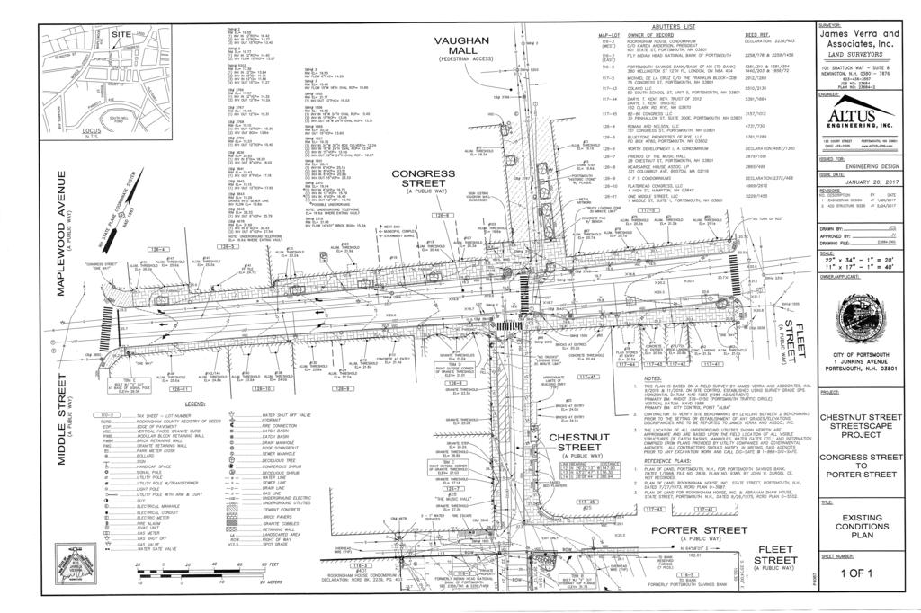
5 Congress and Chestnut Street Streetscape and Utilities Project Portsmouth, NH Geotechnical Investigation Report May 3, PROJECT INFORMATION The following subsections provide general descriptions of the site, the regional geologic setting, and the proposed development. 1.1 Site Description The site of the proposed Congress and Chestnut Street Streetscape and Utilities Project is located on Congress, Chestnut, and Porter Streets in Portsmouth, New Hampshire. The roads are subject to moderate to heavy flow of standard passenger vehicles and delivery trucks, and provide direct access to numerous businesses and residences. An Existing Conditions Plan (attached) provided by Altus Engineering, Inc. and dated January 20, 2017 indicates moderately sloping ground surface contours with existing grades ranging from about +20 feet to +32 feet within the footprint of the proposed development. 1.2 Regional Geologic Setting JTC s review of the Surficial Geologic Map of the Portsmouth and Kittery Quadrangles, Rockingham County, New Hampshire (Larson, G.J.; 1992) indicates that the native soils are likely to vary among Glacial and Postglacial Water-Laid Deposits, Marine Offshore Deposits, and Glacial Till. Glacial and Postglacial Water-Laid Deposits include sand, gravel, and silt deposited by meltwater streams discharging into the late glacial sea and/or wave-derived nearshore deposits during marine offlap. Marine Offshore Deposits typically include marine sand, silt, and/or clay associated with the Presumscot Formation. Glacial Till is generally a heterogeneous mixture of sand, silt, clay, and stones deposited directly by glacial ice. Stratification is rare and it usually overlays bedrock. The referenced map also indicates some areas (typically near West Road) that may include relatively thin (less than 10 feet thick) layers of overburden soils and/or shallow bedrock. 1.3 Proposed Development JTC understands that the proposed development involves the construction of a new ornamental arch to span across the end of Chestnut Street where it terminates at Congress Street. JTC further understands that the underground utilities along the three streets are to be replaced/improved. We understand that design details are still being developed, but the structural engineer, JSN Associates, Inc., provided preliminary site-specific structural loading as follows: The intent will be to support the arch on an isolated shallow spread footing, each approximately 6 to 7 square; and Foundation loads will be on the order of 20 kips or less (less than 10 kips per footing). 2.0 GEOTECHNICAL EXPLORATIONS & LABORATORY TESTING The primary components of the geotechnical exploration and laboratory testing programs are Page 2 of 12
6 Congress and Chestnut Street Streetscape and Utilities Project Portsmouth, NH Geotechnical Investigation Report May 3, 2017 described in the following subsections. 2.1 Geotechnical Explorations Soil Exploration Corp (SoilEx) to perform two (2) geotechnical test borings (designated as B-1 and B-2) and four (4) ledge probes (designated LP-1 through LP-4, inclusive) via a truck-mounted Mobile B57 drill rig. JTC directed the drilling, testing, and sampling activities and logged the subsurface conditions encountered at each exploration location. The proposed exploration locations were selected by the design team. JTC field-located the proposed explorations considering existing site features and proposed development, and under the constraints of drill rig access and utility conflicts. Subsequently, the relative location of each exploration was established via measurements from existing site features and scaling the dimensions onto the provided plan(s). The attached Exploration Location Plan depicts the approximate exploration locations. The test borings were advanced to depths ranging from 11 to feet below the ground surface (bgs) utilizing 2¼-inch inside-diameter continuous-flight hollow-stem-augers (HSAs). As the borings were advanced, standard penetration tests (SPTs) were conducted at regular intervals and soil samples were obtained via 2-inch outside-diameter split-spoon samplers driven by a 140- pound hammer. SPTs were performed in general accordance with ASTM D1586, Standard Test Method for Penetration Test and Split-Barrel Sampling of Soils. Soil samples were sealed in moisture-tight containers and returned to JTC s office for further review, classification, and/or geotechnical laboratory testing. The ledge probes were advanced to depths ranging from 2 to 5.5 feet bgs. The test borings (and probes) were backfilled with soil cuttings upon completion of drilling. Detailed records of the drilling, testing, and sampling performed and the soil, bedrock, and groundwater conditions observed at each test boring location are provided on the attached Test Boring Logs. General descriptions of the subsurface conditions observed at each ledge probe location are provided in the attached Ledge Probe Summary. 2.2 Geotechnical Laboratory Testing JTC selected representative soil samples for geotechnical laboratory testing at our in-house laboratory. The following tests were performed: 6 Moisture contents; 5 Particle-size analyses; and 1 Atterberg Limits. Geotechnical laboratory testing was performed in general accordance with ASTM procedures. Test results are provided on the attached Geotechnical Laboratory Testing Reports. Page 3 of 12
7 Congress and Chestnut Street Streetscape and Utilities Project Portsmouth, NH Geotechnical Investigation Report May 3, SUBSURFACE CONDITIONS The following subsections describe the site soil, bedrock, and groundwater conditions encountered, based on results of the geotechnical explorations and laboratory testing. Detailed descriptions of the conditions observed at each test boring are provided on the attached Test Boring Logs. General descriptions of the conditions observed at each auger probe location are provided in the attached Ledge Probe Summary. 3.1 Soils The overburden soils encountered at the test boring locations appear to be generally consistent with those described by the published geologic data. The primary soil strata are briefly described in the paragraphs below Road Base Road Base materials were encountered directly beneath 3-5 inches of asphalt at each exploration location. The Road Base typically consisted of brown to dark brown silty sand (SM) with few gravel. The Road Base was about 0.5 to 1 feet thick at most exploration locations. The Road Base was typically medium dense and moist Existing Fill Existing Fill materials were encountered directly beneath the Road Base at each test boring location and at most auger probe locations. The Existing Fill was usually described as brown silty sand with gravel (SM) or as brown silty sand (SM). Where encountered (or inferred), the Existing Fill was approximately 1 to 4 feet thick and extended to depths of about 2.5 to 5.5 feet bgs. The Existing Fill was typically described as loose to medium dense to dense based on SPT N-values Marine Offshore Deposits Native soils described as olive brown sandy lean clay (CL) and/or olive brown fine to medium sand (SM) were encountered directly beneath the Fill at each test boring location. This deposit is interpreted to be a Marine Offshore Deposit of Marine Clay and Marine Sand. Where fully penetrated, the clay and/or sand extended to depths ranging from 8.5 to 13.5 feet bgs and was about 3.5 to 8.5 feet thick. The Marine Clay (CL) typically extended to depths ranging from 8.5 to 13.5 feet bgs. The clay was described as medium stiff to very stiff, based on visual-manual observations and SPT N-values that ranged from 8 to 20 and averaged about 12. The moisture content of the clay ranged from about 22.5% to 22.8%, based on two (2) tests. One Atterberg limits determination yielded liquid limit (LL), plastic limit (PL), and plasticity index (PI) values of 26, 17, and 9, respectively. The moisture content was typically above the PL, which is evidenced by a liquidity index (LI) value of 0.6. The available data indicate that the Marine Clay is moderately to heavily overconsolidated. Page 4 of 12
8 Congress and Chestnut Street Streetscape and Utilities Project Portsmouth, NH Geotechnical Investigation Report May 3, 2017 The Marine Sand (SM) was encountered in boring B-2 at 5 feet bgs and extended to a depth of 6 feet bgs. Marine sand was not encountered in boring B-1. The sand was medium dense based on SPT N-values Glacial Till Olive brown silty sand with gravel (SM) was encountered beneath the Marine Offshore Deposits at each boring location at depths ranging from about 8.5 to 13.5 feet bgs. This stratum is interpreted to be Glacial Till. The Glacial Till was fully penetrated (i.e., practical refusal to further penetration of the augers) in both borings, and varied from about 2.5 to 4 feet in thickness and extended to depths ranging from 11 to feet bgs. The Glacial Till was typically described as medium dense to very dense based on N-values that ranged from 25 to 50. One (1) particle-size analysis performed on a representative sample indicated 39% sand, 32% gravel, and 29% silt/clay. The moisture content was 8.1%, based on one (1) test. 3.2 Bedrock Practical refusal to further penetration of the augers and/or split-spoon sampler was encountered at each test boring and ledge probe location at depths ranging from about 2 to feet bgs, and was encountered at depths ranging from 11 to feet in the vicinity of the proposed archway. The refusal in each exploration is interpreted to be refusal on the probable top of bedrock. Bedrock is not expected to impact the construction of the arch, based on the results of this investigation. Bedrock may impact the redevelopment of underground utilities. As such, a limited amount of rock removal should be expected and a variety of removal methods should be anticipated and budgeted for (obtain unit costs), including mechanical excavation, ripping, hoe-ram, and blasting. 3.3 Groundwater Groundwater and/or wet soils were encountered in boring B-2 at a depth of approximately 2 feet bgs, at the time of drilling. Boring B-2 is located in close proximity to a street drain and wet soils are likely due to snow meltwater runoff from sidewalks and street. Short-term (i.e., during drilling, upon completion of drilling, and/or a few hours after drilling) water levels observed in test borings should be considered approximate. Site groundwater levels should be expected to fluctuate seasonally and in response to precipitation events, construction activity, site use, and adjacent site use. 4.0 GEOTECHNICAL DESIGN & CONSTRUCTION RECOMMENDATIONS The evaluation of the site and the proposed development was based on the subsurface conditions encountered at the geotechnical test borings, results of geotechnical laboratory testing, provided site/grading plans, and assumed/preliminary structural loading conditions, as described herein. Page 5 of 12
9 Congress and Chestnut Street Streetscape and Utilities Project Portsmouth, NH Geotechnical Investigation Report May 3, 2017 JTC believes that the site soils are generally suitable for support of the proposed arch, provided the site/subgrade is prepared as described herein. The existing Asphalt, Road Base, and Existing Fill materials are not suitable for direct support of the arch foundations. These soils should be completely removed from the footing zone (i.e., the proposed footing plus at least 5 feet laterally) during the initial phases of site preparation and grading. Subsequently, the proposed arch can be supported upon shallow foundations bearing on undisturbed native Marine Sand/Clay, Glacial Till and/or on Structural Fill or crushed stone builtup from properly prepared native soil subgrades, provided that the design and construction recommendations presented herein are satisfied. 4.1 Site Preparation and Grading Site preparation and grading should be performed in accordance with the following procedures: A geotechnical engineer should directly observe site preparation and grading activities; The site soils contain substantial proportions of fine sand, silt, and clay, and may degrade and/or become unworkable when subjected to construction traffic or other disturbance during wet conditions. As such, site preparations, grading, and earthworks should be performed during a dry season if possible. The Contractor shall be aware of these conditions and must take precautions to minimize subgrade disturbance. Such precautions may include diverting storm run-off away from construction areas, reducing traffic in sensitive areas, minimizing the extent of exposed subgrade if inclement weather is forecast, backfilling excavations and footings as soon as practicable, grading (and compacting) exposed subgrades to promote surface water run-off, and maintaining an effective dewatering program, as necessary. Over-excavation to remove degraded or unworkable subgrade soils should be anticipated and budgeted (cost and schedule); Any existing buildings, structures, and/or associated foundations (including footings, foundation walls, slabs-on-grade, and/or basements) should be completely removed from the proposed arch footprints and replaced/backfilled with properly placed and compacted Structural Fill; Any existing subsurface utilities and underground structures should be completely removed from the footprint of the proposed arch and replaced/backfilled with properly placed and compacted Structural Fill. Any existing subsurface utilities in proposed pavement areas should be removed and/or appropriately abandoned in place (e.g., pressure grouting), as approved by the on-site geotechnical engineer; The site should be cleared and stripped of any existing asphalt-concrete pavement not designated to remain; existing trees/vegetation not designated to remain; Topsoil, rootmat, forest mat; loamy/organic-laden Subsoil; and any otherwise unsuitable materials; o The explorations indicate that most of the site is presently covered with 3 to 5 inches of Asphalt. Existing Fill, Road Base, and any otherwise unsuitable materials should be completely removed from the proposed arch footprint (i.e., the proposed arch footprint plus at least 5 Page 6 of 12
10 Congress and Chestnut Street Streetscape and Utilities Project Portsmouth, NH Geotechnical Investigation Report May 3, 2017 feet laterally); o The geotechnical explorations indicate that Existing Fill materials extend to depths on the order of 5 to 5.5 feet bgs proximate to the proposed arch; and o Additional Undocumented Fill materials should also be expected proximate to existing building(s) and subsurface utilities. In cut areas, the final foot of excavation should be performed using a smooth-edged cutting bucket (no teeth) to minimize subgrade disturbance; Following clearing, stripping, and/or cutting, the exposed subgrade soils should be proofrolled/proof-compacted using a large walk-behind compactor. However, proofrolling/proof-compacting should not be performed if/when the exposed subgrade soils are wet (i.e., due to presence of groundwater, stormwater, perched water, etc.) because this may result in soil pumping and instability. Therefore, the proof-rolling/proof-compacting efforts, including the number of passes and whether to employ static or vibratory methods, should be directed by the on-site geotechnical engineer; o Any loose, soft, wet, and/or otherwise unsuitable soils (typically evidenced by rutting, pumping, and/or deflection of the subgrade) should be over-excavated to expose suitable soils, or other remedial measures should be taken, as approved by the on-site geotechnical engineer; and o The over-excavation should then be backfilled with properly placed and compacted Structural Fill. Structural Fill should be used for subgrade fill within footing pads. The placement of Structural Fill materials to achieve design subgrades in footing pads should not begin until the exposed subgrade soils have been directly observed and approved by the on-site geotechnical engineer; Common Fill is acceptable for subgrade fill in parking and driveway areas. The placement of Common Fill materials to achieve design subgrades in pavement areas should not begin until the exposed subgrade soils have been directly observed and approved by the on-site geotechnical engineer; and Structural Fill and Common Fill materials and placement and compaction requirements are provided in the attached Table Shallow Foundations Based on the subsurface conditions encountered at the exploration locations and our current understanding and assumptions relative to the proposed development, the following preliminary foundation design recommendations are provided: The existing Asphalt, Existing Fill, and Road Base materials are not suitable for direct support of shallow foundations. These materials should be completely removed from the footprint(s) of the arch, plus 5 feet laterally, as described in Section 4.2.1; The arch can be supported on a system of continuous and/or isolated shallow spread footings bearing on undisturbed native Marine Clay/Sand, Glacial Till, and/or on Structural Page 7 of 12
11 Congress and Chestnut Street Streetscape and Utilities Project Portsmouth, NH Geotechnical Investigation Report May 3, 2017 Fill or crushed stone built-up from properly prepared native soil subgrades; Shallow foundations may be designed using an allowable bearing pressure of 3,000 psf.; Isolated column footings should have a minimum width of 3 feet; Exterior footings should be founded at least 4 feet below the lowest adjacent grade to provide adequate frost protection; Total post-construction settlements due to applied foundation loads are estimated to be 0.25 to 0.5 inches or less, based on column footing widths of up to 7 feet. Differential settlements between isolated column footings are estimated to be less than 0.25 inches. The estimated settlements and resulting angular distortion are anticipated to be within the allowable limits for this type of structure; The design of the arch foundation should consider pull-out (uplift), sliding, and overturning due to wind-induced uplift, lateral, and/or rotational loads. o Resistance to net tensile loads (i.e., uplift) can be provided by the weight of the foundation elements, the weight of the soil directly above the foundation elements (if applicable), and the superstructure. The structural designer should evaluate the actual design tensile loads and the actual tensile resistance (i.e., uplift resistance) based upon the actual foundation configuration, targeting a 1.5 factor of safety; o Resistance to lateral loads can be provided by friction along the base of the foundations. An interface friction angle, φ, of about 24 degrees is recommended for mass concrete against silty fine to medium sand and/or stiff clay, which results in a frictional factor, tan φ, of Only dead loads should be used in the calculation of available interface friction; o An active earth pressure coefficient, Ka, of 0.33 and a passive earth pressure coefficient, Kp, of 1.5 (3.0 divided by reduction factor of 2) may be considered for resistance to lateral loads and overturning; and o To resist overturning, the net reaction should be located within the middle third of the footing base. Recommendations for shallow foundation subgrade preparation/construction and foundation backfilling are provided as follows: A geotechnical engineer or his/her representative should directly observe foundation subgrade preparation activities; If shallow and/or perched groundwater is encountered, it must be removed in advance of excavation and continuously maintained at least 2 feet below the bottom of excavation and subsequent construction grade until the backfilling is complete; Excavations for shallow foundations must extend into undisturbed native Marine Clay/Sand, Glacial Till and/or Structural Fill built-up from properly prepared native soils, as described herein; The native foundation subgrade soils will be sensitive to moisture and will readily disturb Page 8 of 12
12 Congress and Chestnut Street Streetscape and Utilities Project Portsmouth, NH Geotechnical Investigation Report May 3, 2017 or soften if exposed to wet conditions and construction activities. Therefore, the final foot, at a minimum, of excavation for foundations should be performed using a smooth-edged cutting bucket (no teeth) to minimize subgrade disturbance. If seepage/shallow groundwater and/or precipitation result in wet conditions, the exposed foundation subgrade should be protected with a 6-inch (minimum) thick layer of ¾-inch minus crushed stone encased in a geotextile fabric (e.g., Mirafi 140N or equal). The crushed stone shall be placed immediately upon exposure of the native foundation subgrade soils and densified with a plate compactor until exhibiting stable conditions. The purpose of the crushed stone is to protect the fine-grained subgrade soils from disturbance, facilitate construction dewatering (if necessary), and provide a dry/stable subgrade upon which to progress construction; o If Undocumented Fill and/or otherwise unsuitable soils/materials are encountered at the foundation subgrade, over-excavations should remove all Fill and/or unsuitable soils within the footing zone of influence, which is defined as the area extending laterally 1 foot from edges of the footing and then outward and downward at a 1H:1.5V (horizontal to vertical) splay of bearing until a suitable native subgrade soil is encountered; and o Any over-excavations should be backfilled with properly placed and compacted Structural Fill or crushed stone as approved by the on-site geotechnical engineer. Prior to setting forms and placing reinforcing steel, a geotechnical engineer should directly observe footing subgrades; o Footing subgrades should be level or suitably benched and free of standing water and/or debris; o Loose, soft, wet, frozen, or otherwise unsuitable soils should either be re-compacted or over-excavated to a suitable subgrade, as approved by the on-site geotechnical engineer; and o Over-excavations should be backfilled with properly placed and compacted Structural Fill or crushed stone as approved by the on-site geotechnical engineer. Foundation subgrade soils should be protected against physical disturbance, precipitation, and/or frost throughout construction. Surface water run-on/run-off should be diverted away from open foundation excavations. The Contractor shall ultimately be responsible for the means and methods to protect the foundation subgrade during construction; Exterior footings and piers should be backfilled with non-frost-susceptible fill in order to mitigate potential adverse effects of frost. Backfill for exterior footings and piers should consist of well-graded, free-draining, granular soil conforming to the requirements of Clean Granular Fill, as described in the attached Table 1. Alternatively, a suitable bond break (such as rigid polystyrene insulation) may be provided as approved by the on-site geotechnical engineer. In this case, footings may be backfilled with Common Fill (see attached Table 1) having a maximum particle-size of 3 inches, as approved by the on-site geotechnical engineer; Backfill for footings and piers should be placed in uniform horizontal lifts having a maximum loose lift thickness of 8 inches and compacted to 95 percent of its modified proctor Page 9 of 12
13 Congress and Chestnut Street Streetscape and Utilities Project Portsmouth, NH Geotechnical Investigation Report May 3, 2017 maximum dry density (MPMDD; per ASTM D1557). Thinner lifts may be required in order to achieve the required compaction criteria; and 4.3 Protection of Existing Foundations JTC recommends that where the new arch foundation is within close proximity to the existing buildings, that the new footings be constructed at similar grade as the existing footings to mitigate the overlapping of stresses. An imaginary line drawn between the lower edges of adjoining/adjacent footings shall not have a steeper slope than 26.5 (2H:1V) relative to horizontal unless the materials supporting the higher footing are braced or otherwise retained. Furthermore, in no case should the FZOI of the existing foundation be encroached or disturbed without review by a Professional Engineer. The FZOI is defined as that area extending laterally 1 foot from the edge of the existing footing then projecting laterally outward and downward at a 1H:1V splay. Data from the borings suggests that the existing foundation could be undermined during the removal of Existing Fill. As such, temporary excavation support and/or foundation underpinning may be required for that approach. If the existing footings do need to be undermined, it is expected that conventional concrete pit underpinning will be the most practical means of support. Such underpinning involves staggered limited-width excavations beneath the existing foundation and subsequent backfilling of the pits with new concrete. The process essentially lowers the bottom of footing (BOF) of the existing foundation. It is recommended that an experienced Contractor be retained for the underpinning. The Contractor should provide a Technical Submittal to outline their proposed means and methods to protect the existing building and construct the new underpinning pits. JTC can provide technical assistance if underpinning or shoring is necessary for the project. 4.4 Seismic Considerations A site class C is recommended based on site class definitions of the American Society of Civil Engineers (ASCE) Standard 7-10, Minimum Design Loads for Buildings and Other Structures. The site is not considered to be susceptible to liquefaction, based on the conditions encountered at the test boring locations. 4.5 Re-Use of Site Soils Most of the Existing Fill, Road Base, and Glacial Till encountered at the exploration locations should be suitable for re-use as Common Fill, provided that it is appropriately segregated from excessively silty, wet, and/or otherwise unsuitable materials. The Existing Fill, Road Base, and Glacial Till are not expected to be suitable for re-use as Clean Granular Fill or Structural Fill. The Marine Clay and Marine Sand encountered at the exploration locations are not suitable for reuse as Structural Fill, Clean Granular Fill, or Common Fill. These soils may be re-used in areas to be landscaped, subject to conformance with the project specifications. Page 10 of 12
14 Congress and Chestnut Street Streetscape and Utilities Project Portsmouth, NH Geotechnical Investigation Report May 3, Construction Monitoring and Quality Control Testing A qualified geotechnical engineer or representative should be retained to review the site preparation and grading activities and foundation subgrade preparations, at a minimum. Similarly, quality control testing, including in-place field density and moisture tests, should be performed to confirm that the specified compaction is achieved. It is recommended that JTC be retained to provide earthwork construction monitoring and quality control testing services. Quality control testing recommendations are provided as follows: During site grading and foundation subgrade preparation, 1 field density test should be performed for every lift (maximum 8 inches per lift) of Structural Fill placement, at a minimum; During foundation and/or pier backfilling, 1 field density test should be performed for every lift (maximum 8 inches per lift) of Clean Granular Fill placement, at a minimum; and During backfilling of utility trenches, at least 1 test should be conducted on Structural Fill for every lift (maximum 8 inches per lift) of trench. 4.7 Additional Considerations Additional design recommendations are provided as follows: Exterior concrete sidewalks shall be underlain by at least 15 inches of Clean Granular Fill. The thickness of the Clean Granular Fill shall be increased to no less than 24 inches for exterior concrete slabs located adjacent to exterior doorways and ramps to provide additional frost protection at building entry/exit points; The exterior ground surface adjacent to buildings should be sloped away from the building to provide for positive drainage. Similarly, the final surface materials adjacent to buildings should be relatively impermeable to reduce the volume of precipitation infiltrating into the subsurface proximate to building foundations. Such impermeable materials include cement concrete, bituminous concrete, and/or vegetated silty/clayey topsoil; and Permanent fill or cut slopes should have a maximum slope of 2.5H:1V (horizontal to vertical) or flatter for dry conditions. Permanent fill or cut slopes should be no steeper than 3H:1V for wet/submerged conditions (e.g., stormwater basin) unless a properly designed surface slope stabilization system (e.g. rip rap, geosynthetics) is provided. Additional construction recommendations are provided as follows: Safe temporary excavation and/or fill slopes are the responsibility of the Contractor. Excavations should be conducted in accordance with local, state, and federal (OSHA) requirements, at a minimum. If an excavation cannot be properly sloped or benched due to space limitations, adjacent structures, and/or seepage, the Contractor should install an Page 11 of 12
15 Congress and Chestnut Street Streetscape and Utilities Project Portsmouth, NH Geotechnical Investigation Report May 3, 2017 engineered shoring system to support the temporary excavation; Subgrade conditions will be influenced by excavation methods, precipitation, stormwater management, groundwater control(s), and/or construction activities. Most of the site soils are poorly-drained, moisture-sensitive, and considered susceptible to disturbance when exposed to wet conditions and construction activities. As such, the Contractor shall be aware of these conditions and must take precautions to minimize subgrade disturbance. Such precautions may include diverting storm run-off away from construction areas, reducing traffic in sensitive areas, minimizing the extent of exposed subgrade if inclement weather is forecast, backfilling excavations and footings as soon as practicable, and maintaining an effective dewatering program, as necessary; Proper groundwater control and stormwater management are necessary to maintain site stability. Groundwater should be continuously maintained at least 2 feet below the working construction grade until earthworks and/or backfilling are complete; If groundwater seepage and/or wet soils due to shallow groundwater are observed, a ¾- inch minus crushed stone base should be placed atop the exposed subgrade soils. The stone should be immediately placed atop the undisturbed subgrade and then tamped with a plate compactor until exhibiting stable conditions. The stone shall be protected, as required, with a geotextile filter fabric such as Mirafi 140N or equal. The purpose of the stone base is to protect the wet subgrade, facilitate dewatering, and provide a dry/stable base upon which to progress construction; and All slopes should be protected from erosion during (and after) construction. 5.0 CLOSING We trust the contents of this report are responsive to your needs at this time. Should you have any questions or require additional assistance, please do not hesitate to contact our office. Page 12 of 12
16 Explorations LIMITATIONS 1. The analyses and recommendations presented in this report are based in part upon the data obtained from widely-spaced subsurface explorations. Subsurface conditions between exploration locations may vary from those encountered at the exploration locations. The nature and extent of variations between explorations may not become evident until construction. If variations appear, it will be necessary to re-evaluate the recommendations of this report. 2. The generalized soil profile described in the text is intended to convey trends in subsurface conditions. The boundaries between strata are approximate and idealized and have been developed by interpretation of widely-spaced explorations and samples; actual strata transitions are probably more gradual. For specific information, refer to the individual test pit and/or boring logs. 3. Water level readings have been made in the test pits and/or test borings under conditions stated on the logs. These data have been reviewed and interpretations have been made in the text of this report. However, it must be noted that fluctuations in the level of the groundwater may occur due to variations in rainfall, temperature, and other factors differing from the time the measurements were made. Review 4. It is recommended that John Turner Consulting, Inc. be given the opportunity to review final design drawings and specifications to evaluate the appropriate implementation of the geotechnical engineering recommendations provided herein. 5. In the event that any changes in the nature, design, or location of the proposed areas are planned, the conclusions and recommendations contained in this report shall not be considered valid unless the changes are reviewed and conclusions of the report modified or verified in writing by John Turner Consulting, Inc. Construction 6. It is recommended that John Turner Consulting, Inc. be retained to provide geotechnical engineering services during the earthwork phases of the work. This is to observe compliance with the design concepts, specifications, and recommendations and to allow design changes in the event that subsurface conditions differ from those anticipated prior to the start of construction. Use of Report 7. This report has been prepared for the exclusive use of City of Portsmouth in accordance with generally accepted soil and foundation engineering practices. No other warranty, expressed or implied, is made. 8. This report has been prepared for this project by John Turner Consulting, Inc. This report was completed for preliminary design purposes and may be limited in its scope to complete an accurate bid. Contractors wishing a copy of the report may secure it with the understanding that its scope is limited to preliminary geotechnical design considerations.
17 TABLE 1 Recommended Soil Gradation & Compaction Specifications Structural Fill SIEVE SIZE PERCENT PASSING BY WEIGHT 5-inch 100 ¾-inch No No NOTES: 1. For use as structural load support below foundations and as subgrade fill within building pads. Structural Fill placed beneath building foundations should include the Footing Zone of Influence which is defined as that area extending laterally one foot from the edge of the footing then outward and downward at a 1H:1.5V splay. 2. ¾-inch crushed stone may be used in wet conditions. 3. Structural Fill should be free of construction and demolition debris, frozen soil, organic soil, peat, stumps, brush, trash, and refuse; 4. Structural Fill should not be placed on soft, saturated, or frozen subgrade soils; 5. Structural Fill should be placed in lifts not exceeding 12 inches for heavy vibratory rollers and 8 inches for vibratory plate compactors. 6. Place and compact within ± 3% of optimum moisture content. 7. Compact to at least 95% relative compaction per ASTM D The adequacy of the compaction efforts should be verified by field density testing.
18 Clean Granular Fill SIEVE SIZE PERCENT PASSING BY WEIGHT 3-inch 100 ¾-inch No No NOTES: 1. For minimum 9-inch base below floor slabs-on-grade. 2. For minimum 15-inch base for exterior concrete slabs exposed to frost. 3. For minimum 24-inch base at exterior ramps, aprons, and loading bays adjacent to entrances/exit ways. 4. For use as footing and foundation wall backfill. 5. For use as backfill behind unbalanced foundation/retaining walls. 6. Place in lifts not exceeding 12 inches for heavy vibratory rollers and 8 inches for vibratory plate compactors. 7. Place and compact within ± 3% of optimum moisture content. 8. Compact to at least 95% relative compaction per ASTM D Compaction efforts should be verified by field density testing. Common Fill SIEVE SIZE PERCENT PASSING BY WEIGHT 6-inch 100 ¾-inch No No NOTES: 1. For use as common/subgrade fill for athletic fields, parking areas, and embankments. 2. For use as foundation wall backfill if used in conjunction with a bond break and sized/screened to 3-inch minus. 3. Place in lifts not exceeding 12 inches. 4. Maximum stone size should not exceed ½ the actual lift thickness. 5. Compact to at least 92% relative compaction per ASTM D1557 when placed as subgrade fill in parking areas or roadway embankments. 6. Compact to at least 95% relative compaction per ASTM D1557 when placed as foundation wall backfill in conjunction with a bond break. 7. Compaction efforts should be verified by field density testing.
19 Existing Conditions Plan, Site Plan, Archway Foundation Plan, & Exploration Location Plan
20
21

22


23 LP-2 B-2 B-1 = boring = ledge probe LP-3 LP-4 LP-1 Notes: 1. Explorations were performed on March 22, 2017 under the direction of JTC. 2. Exploration locations should be considered approximate. 3. Refer to the Test Boring Logs and Summary of Auger Probes for the subsurface conditions encountered at each exploration location. 4. Basemap source: January 20, 2017 Existing Conditions Plan prepared by Altus Engineering, Inc. 5. Not to scale. City of Portsmouth 1 Junkins Avenue Portsmouth, New Hampshire Congress and Chestnut Street Streetscape and Utilities Project Portsmouth, New Hampshire EXPLORATION LOCATION PLAN
24 Test Boring Logs, Key to Symbols and Descriptions, & Ledge Probe Summary
25 This information pertains only to this boring and should not be interpreted as being indicative of the site. LOG OF BORING No. B-1 Depth (feet) PROJECT: Congress and Chestnut Street Streetscape and Utilities Project CLIENT: City of Portsmouth PROJECT LOCATION: Chestnut Street, Portsmouth NH LOCATION: See Exploration Location Plan DRILLER: SoilEx 4.5" Asphalt Dark brown, silty sand (SM) - few gravel medium dense; moist: ROAD BASE Brown, silty sand (SM) - few gravel; medium dense; moist: FILL - Becomes loose 5.5 Olive brown, sandy lean clay (CL) - stiff; moist: MARINE CLAY Pen Su = 2,500 psf Torvane Su = 400 psf Olive brown, silty sand w/ gravel (SM) - very dense; moist: GLACIAL TILL - Rock in tip Boring terminated at 11 ft. Auger refusal on probable bedrock 8.5 SS01 SS02 SS03 SS /5" PROJECT NO.: ELEVATION: LOGGED BY: DRILLING METHOD: HSA DATE: 3/22/17 DEPTH TO - WATER> INITIAL: AFTER 24 HOURS: Description Graphic Elevation (feet) Sample No. Blow Counts % < #200 RC TEST RESULTS Plastic Limit Liquid Limit Water Content - Penetration Figure PAGE 1 of 1
26 This information pertains only to this boring and should not be interpreted as being indicative of the site. LOG OF BORING No. B-2 Depth (feet) PROJECT: Congress and Chestnut Street Streetscape and Utilities Project CLIENT: City of Portsmouth PROJECT LOCATION: Chestnut Street, Portsmouth NH LOCATION: See Exploration Location Plan DRILLER: SoilEx 5" Asphalt 0.4 Tan brown, silty sand (SM) - few gravel; medium dense; moist: ROAD BASE Brown, silty sand with gravel (SM) - loose; moist: FILL - Becomes wet (located near street drain) Olive brown, fine to medium sand (SM) - trace silt; medium dense; moist: MARINE SAND Olive brown, sandy lean clay (CL) - very stiff; moist: MARINE CLAY Pen Su = 3,000 psf Torvane Su = 400 psf - Becomes medium stiff Pen Su = 1,500 psf Torvane Su = 400 psf SS01 SS02 SS03 SS04 SS PROJECT NO.: ELEVATION: LOGGED BY: DRILLING METHOD: HSA DATE: 3/22/17 DEPTH TO - WATER> INITIAL: AFTER 24 HOURS: Description Graphic Elevation (feet) Sample No. Blow Counts % < #200 RC TEST RESULTS Plastic Limit Liquid Limit Water Content - Penetration Olive brown, silty sand w/ gravel (SM) - medium dense; moist: GLACIAL TILL SS Auger refusal on probable bedrock Boring terminated at ft. Figure PAGE 1 of 1
 SANDS (50% or more of coarse fraction PASSES the No.")
27 COARSE GRAINED SOILS (More than 50% RETAINED on No. 200 sieve) FINE GRAINED SOILS (50% or more PASSES the No. 200 sieve) MAJOR DIVISIONS GRAVELS (More than 50% of coarse fraction RETAINED on No. 4 sieve) SANDS (50% or more of coarse fraction PASSES the No. 4 sieve) CLEAN GRAVELS (Less than 5% fines) GRAVELS WITH FINES (More than 12% fines) CLEAN SANDS (Less than 5% fines) SANDS WITH FINES (More than 12% fines) SILTS AND CLAYS (Liquid Limit LESS than 50) SILTS AND CLAYS (Liquid Limit of 50 or GREATER) HIGHLY ORGANIC SOILS SAND GC Silty gravels or gravel-sand-silt mixtures. Well graded sands or sand-gravel mixtures; trace or no fines. Inorganic lean clay. Low to medium plasticity. PI > 7 and plots on or above "A" line. BOUNDARY CLASSIFICATIONS: Soils possessing characteristics of two groups are designated by combinations of group symbols. SILT OR CLAY Fine GROUP SYMBOLS Medium GM SM SC ML Fine No.200 No.40 No.10 No.4 U.S. STANDARD SIEVE SIZE Organic silts, clays, and silty clays. Low to medium plasticity. Inorganic elastic silt. PI plots below "A" line. Organic silts and clays. High plasticity. Peat and other highly organic soils. Decomposed vegetable tissue. Fibrous to amorphous texture. GRAVEL 3/4" Coarse 3" Cobbles Boulders References: ASTM D 2487 (Unified Soil Classification System) and ASTM D 2488 (Visual-Manual Procedure). GW GP SW SP CL OL MH CH OH PT Coarse GENERAL DESCRIPTIONS Well graded gravels or gravel-sand mixtures; trace or no fines. Poorly graded gravels or gravel-sand mixtures; trace or no fines. Clayey gravels or gravel-sand-clay mixtures. Poorly graded sands or sand-gravel mixtures, trace or no fines. Silty sands or sand-gravel-silt mixtures. Clayey sands or sand-gravel-clay mixtures. Inorganic silts or rock flour. Non-plastic or very slightly plastic. PI < 4 or plots below "A" line. Inorganic fat clay. High plasticity. PI plots on or above "A" line. 12" Shelby Tube Standard Split Spoon Sample Rock Core Vane Shear Geoprobe Sample Water Table at time of drilling TYPICAL SYMBOLS Auger Cuttings 3" Split Spoon Sample Dynamic Cone Penetrometer Bulk/Grab Sample Sonic or Vibro-Core Sample Water Table after 24 hours CORRELATION OF STANDARD PENETRATION TEST (SPT) WITH RELATIVE DENSITY AND CONSISTENCY GRAVEL, SAND, & SILT (NON-PLASTIC) SILT (PLASTIC) & CLAY N-Value Relative Density N-Value Su (psf) Consistency 0-4 Very Loose Very Soft 4-10 Loose Soft Medium Dense Medium Stiff Dense Stiff Over 50 Very Dense Very Stiff Over 30 Over 4000 Hard SPT Notes: WR = Weight of Rods; WH = Weight of Hammer TERMS DESCRIBING SOILS TERMS DESCRIBING MATERIALS (excludes particles > 3", organics, debris, etc.) (i.e. particles > 3", organics, debris, etc.) Trace: Particles present, but < 5% Occasional: Particles present, but < 10% Few: 5% to 15% Frequent: 10% to 25% Little: 15% to 25% Many: > 25% Some: 25% to 50% TERMS DESCRIBING MOISTURE TERMS DESCRIBING STRUCTURE Dry: Moist: Wet: Absence of moisture; dusty Damp, but no visible water Visible/free water Layer: Seam: Parting: > 3" thick 1/16" to 3" thick < 1/16" thick KEY TO SYMBOLS AND DESCRIPTIONS
28 Client: Project: City of Portsmouth Congress and Chestnut Street Streetscape and Utilities Project JTC Proj. No.: Drill Date(s): 03/22/17 JTC Rep.: Rachel Cannon Driller: SoilEx SUMMARY OF LEDGE PROBE FINDINGS Probe No. Asphalt Thickness Road Base Thickness Existing Fill Thickness Depth to Ledge Depth to Water Location (inches) (inches) (ft) (ft bgs) (ft bgs) (street name) LP-1 4 approx N/A Porter LP-2 4 approx N/A Congress LP-3 5 approx N/A Chestnut LP-4 3 approx N/A Porter Notes Encountered former concrete sewer main at 0.75ft bgs. Offset 18" to south; same results. Abndoned location per client request. Ecountered concrete at 1ft bgs. Offset to east (approx. 18 inches from curb); same results. Drill through concrete into ledge. Notes: 1 Stratum thicknesses are based on visual observations of cuttings and drilling difficulty and should be considered approximate.
29 Geotechnical Laboratory Testing Reports
30 #200 #140 #100 #60 #40 #30 #20 #10 #4 3/8 in. ½ in. ¾ in. 1 in. 1½ in. 2 in. 3 in. 6 in. Particle Size Distribution Report PERCENT FINER GRAIN SIZE - mm. % Gravel Coarse Fine % Cobbles Coarse % Sand Medium % Fines Fine 20.8 Clay 43.2 TEST RESULTS 16.9 Material Description Percent Spec.* Pass? Size Finer (Percent) (X=Fail) 3/4 1/2 3/8 #4 #10 #20 #40 #50 #100 # Opening Silt Silty sand Atterberg Limits (ASTM D 4318) PL= LL= PI= Classification USCS (D 2487)= SM AASHTO (M 145)= Coefficients D90= D50= D10= D85= D30= Cu = D60= D15= Cc= Remarks In-Situ Moisture: 19.2% Date Received: Tested By: Ted Moody Date Tested: Checked By: Travis Carpenter Title: VP of Geotech Engineering * (no specification provided) Location: B-1(S-2) Sample Number: Date Sampled: Depth: 2-4' Client: City of Portsmouth Project: Congress and Chestnut Street Streetscape and Utilities Project Project No: Figure 001
31 #200 #140 #100 #60 #40 #30 #20 #10 #4 3/8 in. ½ in. ¾ in. 1 in. 1½ in. 2 in. 3 in. 6 in. Particle Size Distribution Report PERCENT FINER GRAIN SIZE - mm. % Gravel Coarse Fine % Cobbles Coarse 0.0 % Sand Medium 0.0 % Fines Fine 0.8 Clay 20.6 TEST RESULTS 78.6 Material Description Sandy Lean clay Percent Spec.* Pass? Size Finer (Percent) (X=Fail) #20 #40 #50 #100 # Opening Silt Atterberg Limits (ASTM D 4318) PL= LL= PI= Classification USCS (D 2487)= CL AASHTO (M 145)= Coefficients D90= D50= D10= D85= D30= Cu = D60= D15= Cc= Remarks In-Situ Moisture: 22.5% Date Received: Tested By: Jason Spry Date Tested: Checked By: Travis Carpenter Title: VP of Geotech Engineering * (no specification provided) Location: B-1(S-3) Sample Number: Date Sampled: Depth: 5'-7' Client: City of Portsmouth Project: Congress and Chestnut Street Streetscape and Utilities Project Project No: Figure 002
32 #200 #140 #100 #60 #40 #30 #20 #10 #4 3/8 in. ½ in. ¾ in. 1 in. 1½ in. 2 in. 3 in. 6 in. Particle Size Distribution Report PERCENT FINER GRAIN SIZE - mm. % Gravel Coarse Fine % Cobbles Coarse TEST RESULTS % Fines Fine 10.9 Silt Clay Material Description Silty sand with gravel Percent Spec.* Pass? Size Finer (Percent) (X=Fail) 1 3/4 1/2 3/8 #4 #10 #20 #40 #50 #100 # Opening % Sand Medium Atterberg Limits (ASTM D 4318) PL= LL= PI= Classification USCS (D 2487)= SM AASHTO (M 145)= Coefficients D90= D50= D10= D85= D30= Cu = D60= D15= Cc= Remarks In-Situ Moisture: 8.1% Date Received: Tested By: Jason Spry Date Tested: Checked By: Travis Carpenter Title: VP of Geotech Engineering * (no specification provided) Location: B-1(S-4) Sample Number: Date Sampled: Depth: 10'-12' Client: City of Portsmouth Project: Congress and Chestnut Street Streetscape and Utilities Project Project No: Figure 003
33 #200 #140 #100 #60 #40 #30 #20 #10 #4 3/8 in. ½ in. ¾ in. 1 in. 1½ in. 2 in. 3 in. 6 in. Particle Size Distribution Report PERCENT FINER GRAIN SIZE - mm. % Gravel Coarse Fine % Cobbles Coarse TEST RESULTS % Fines Fine 19.0 Silt Clay Material Description Well-graded gravel with sand Percent Spec.* Pass? Size Finer (Percent) (X=Fail) 1 3/4 1/2 3/8 #4 #10 #20 #40 #50 #100 # Opening % Sand Medium Atterberg Limits (ASTM D 4318) PL= LL= PI= Classification USCS (D 2487)= GW AASHTO (M 145)= Coefficients D90= D50= D10= D85= D30= Cu= D60= D15= Cc= 1.81 Remarks In-Situ Moisture: 3.3% Date Received: Tested By: Jason Spry Date Tested: Checked By: Travis Carpenter Title: VP of Geotech Engineering * (no specification provided) Location: LP-1 Asphalt Sample Number: Date Sampled: Depth: 0' Client: City of Portsmouth Project: Congress and Chestnut Street Streetscape and Utilities Project Project No: Figure 004

34 #200 #140 #100 #60 #40 #30 #20 #10 #4 3/8 in. ½ in. ¾ in. 1 in. 1½ in. 2 in. 3 in. 6 in. Particle Size Distribution Report PERCENT FINER GRAIN SIZE - mm. % Gravel Coarse Fine % Cobbles Coarse % Sand Medium % Fines Fine 22.5 Clay 32.3 TEST RESULTS 22.5 Material Description Percent Spec.* Pass? Size Finer (Percent) (X=Fail) 3/4 1/2 3/8 #4 #10 #20 #40 #50 #100 # Opening Silt Silty sand Atterberg Limits (ASTM D 4318) PL= LL= PI= Classification USCS (D 2487)= SM AASHTO (M 145)= Coefficients D90= D50= D10= D85= D30= Cu = D60= D15= Cc= Remarks In-Situ Moisture: 10.0% Date Received: Tested By: Ted Moody Date Tested: Checked By: Travis Carpenter Title: VP of Geotech Engineering * (no specification provided) Location: LP-1 Road Base Sample Number: Date Sampled: Depth: 0.5' Client: City of Portsmouth Project: Congress and Chestnut Street Streetscape and Utilities Project Project No: Figure 005
35 GEOTECHNICAL ENVIRONMENTAL RESIDENT ENGINEERING TESTING Boring No. Summary of Moisture Content Testing ASTM D2216 Congress and Chestnut Street Streetscape and Utilities Project Portsmouth, NH Sample Depth (ft bgs) Moisture Content (%) B-2(S-4) Notes: 1. This table summarizes results of stand-alone moisture content testing performed on selected samples. Additional moisture content test results are provided on the associated Particle-Size Distribution Report, Summary of Atterberg Limits Testing Report, Summary of Organic Content Testing Report, and/or other geotechnical laboratory testing reports, as applicable. Tested by: Checked by: JY TC DOVER, NH I WORCESTER, MA I WESTFIELD, MA I PORTLAND, ME I WEST HARTFORD, VT I JOHNSTON, RI
 (%) B-1(S-3) 5-7 22.")
36 GEOTECHNICAL ENVIRONMENTAL RESIDENT ENGINEERING TESTING Summary of Atterberg Limits Testing ASTM D4318 Congress and Chestnut Street Streetscape and Utilities Project Portsmouth, NH Boring No. Sample Depth Moisture Content Liquid Limit Plastic Limit Plasticity Index Liquidity Index USCS Classification (ft bgs) (%) B-1(S-3) CL Tested by: Checked by: JY TC PORTLAND, ME I DOVER, NH I WEST HARTFORD, VT I WORCESTER, MA I WESTFIELD, MA I JOHNSTON, RI
37 Site Photographs


38 SITE PHOTOGRAPHS CONGRESS AND CHESTNUT STREET STREETSCAPE AND UTILITIES PROJECT PORTSMOUTH, NEW HAMPSHIRE Proposed location of arch, To Northeast Proposed location of arch, To North Multiple utility conflicts at Chestnut & Porter Set up on LP-3, to North Sample of FILL in B-2 Sample of native SAND in B-2 Page 1 of 1
April 7, Webster Street Sub-Surface Stormwater Storage System Bid No Bid Date: 4/13/17 ADDENDUM NO 1
 PUBLIC WORKS DEPARTMENT David A. Jones, P.E., Director April 7, 2017 Webster Street Sub-Surface Stormwater Storage System Bid No. 2017-022 Bid Date: 4/13/17 ADDENDUM NO 1 Please make the following changes
Geotechnical Investigation Long Timber Brewing Building Highway 99 and Kelly Street Monroe, Oregon TABLE OF CONTENTS
 Highway 99 and Kelly Street TABLE OF CONTENTS PROJECT INFORMATION... 1 FIELD EXPLORATION... 1 SITE CONDITIONS... 2 Surface Conditions:... 2 Subsurface Conditions:... 2 FILL.... 2 Topsoil.... 2 Clay Alluvium....
CONTRACT 5E-2 APPENDIX A - TEST HOLE LOGS DYREGROV ROBINSON INC. PORTAGE AVE WINSTON DR BOURKEVALE CAVELL PARKSIDE DR ASSINIBOINE AVE
 APPENDIX A - TEST HOLE LOGS PORTAGE AVE TH -9 CONTRACT E- DR DR BOURKEVALE CAVELL WINSTON DR PARKSIDE DR ASSINIBOINE AVE AUTHORIZED BY: DATE: CONSULTING GEOTECHNICAL ENGINEERS AUTHORIZED /0/ CLIENT DRAWING
Civil Geotechnical Surveying
 Civil Geotechnical Surveying Mr. David Burnett Cabarrus County Schools 4425 Old Airport Road Charlotte, North Carolina 28025 May 16, 2017 Reference: Geotechnical Engineering Evaluation Future PLC Site
GEOTECHNICAL INVESTIGATION PROPOSED OUTFALL LOCATION CITY OF MORGAN S POINT DRAINAGE HARRIS COUNTY, TEXAS REPORT NO
 GEOTECHNICAL INVESTIGATION PROPOSED OUTFALL LOCATION CITY OF MORGAN S POINT DRAINAGE HARRIS COUNTY, TEXAS REPORT NO. 1140198001 Reported to: SIRRUS ENGINEERS, INC. Houston, Texas Submitted by: GEOTEST
SECTION SOILS REPORT
 SECTION 02300 SOILS REPORT 1. GENERAL: 1.1 All work included under this heading shall be subject to the General Conditions of the entire operation. This Contractor is required to refer especially thereto.
Applied GeoScience, Inc Hammond Dr., Suite 6 Schaumburg, Illinois
 AGI Project No. 13-276 Subsurface Investigation Report For the Proposed New Retail Center 9601 South Pulaski Road Evergreen Park, Illinois Prepared for Mr. Feras Sweis FHS Design + Build LLC 2010 West
Geotechnical Investigation Report
 Geotechnical Investigation Report Proposed,000-Gallon Water Storage Tank Fagasa Pass Tank Upper Pago Pago, American Samoa Prepared for: ASPA Water Engineering Division Tafuna, American Samoa PO Box PPB
EXHIBIT G GEOTECHNICAL REPORT (DRAFT)
") EXHIBIT G GEOTECHNICAL REPORT (DRAFT) APPENDIX 1 PROJECT SITE 'B' B-1 B-2 I-2 B-3 B-4 B-5 I-1 PROJECT LOCATION LEGEND B-1 = APPROXIMATE BORING LOCATION I-1 = APPROXIMATE INFILTRATION
EXHIBIT G GEOTECHNICAL REPORT (DRAFT) APPENDIX 1 PROJECT SITE 'B' B-1 B-2 I-2 B-3 B-4 B-5 I-1 PROJECT LOCATION LEGEND B-1 = APPROXIMATE BORING LOCATION I-1 = APPROXIMATE INFILTRATION
In preparation for constructing buildings on a property, the builder. Site Preparation CHAPTER
 CHAPTER 3 Site Preparation In preparation for constructing buildings on a property, the builder must consider a number of factors related to code requirements. The buildings must be located according to
May 2, Mr. Tim Kurmaskie, AIA ARCHITECT KURMASKIE ASSOCIATES, INC Washington Street Raleigh, NC
 Mr. Tim Kurmaskie, AIA ARCHITECT KURMASKIE ASSOCIATES, INC. 1030 Washington Street Raleigh, NC 27605-1258 May 2, 2017 Re: Report of Subsurface Investigation Westfield Rehabilitation & Health Care Additions
 FIGURES Printed By: aday Print Date: 3/23/2011 12:48:08 PM File Name: \\geodesign.local\files\jobs\m-r\penskeauto\penskeauto-1\penskeauto-1-01\figures\cad\penskeauto-1-01-vm01.dwg Layout: FIGURE 1 VICINITY
Subsurface Investigation Report. Proposed New 1-Story Building 6447 Grand Avenue Gurnee, Illinois
 AGI Project No. -11 Subsurface Investigation Report For the Proposed New 1-Story Building 6447 Grand Avenue Gurnee, Illinois Prepared for Mr. Steve Panko Key Development Partners, LLC North State Street,
GEOTECHNICAL ENGINEERING REPORT
 GEOTECHNICAL ENGINEERING REPORT Project: NW Bucklin Hill at Silverdale Way NW Project Number: 12023 Prepared for: Barber Development P.O. Box 473 Redmond, WA 98073 Prepared by: South Sound Geotechnical
B. Borrow: Satisfactory soil imported from off-site for use as fill or backfill.
 SECTION 312000- EARTHWORK PART 1 - GENERAL 1.1 RELATED DOCUMENTS Drawings and general provisions of the Contract, including General and Special Conditions, apply to this Section. 1.2 SUMMARY This Section
UTS of Massachusetts, Inc. 5 Richardson Lane Stoneham, MA (p) / (f) utsofmass.com MEMORANDUM
 / (f) utsofmass.com MEMORANDUM") UTS of Massachusetts, Inc. Richardson Lane Stoneham, MA 0280 78-438-77 (p) / 78-438-626 (f) utsofmass.com MEMORANDUM TO: FROM: DRW Construction Services, Inc. 2 Brawley Avenue Fairhaven, Massachusetts
UTS of Massachusetts, Inc. Richardson Lane Stoneham, MA 0280 78-438-77 (p) / 78-438-626 (f) utsofmass.com MEMORANDUM TO: FROM: DRW Construction Services, Inc. 2 Brawley Avenue Fairhaven, Massachusetts
June i TABLE OF CONTENTS
 June 2005 - i - 05-526 TABLE OF CONTENTS SECTION PAGE 1.0 INTRODUCTION... 1 1.1 Purpose of the Investigation... 1 1.2 Description of the Project and Scope of Work... 1 1.3 Site Geology... 1 1.4 Site Description
 Appendix A - Vicinity Map Vicinity Map: Palm Beach Gardens City Hall Additions, 000 N Military Trail, Palm Beach Gardens, FL Proposed Location of Police Dept. Attached Addition Proposed Location of New
Typical Subsurface Profile. November 28, 2016
 November 28, 2016 RSCCD Facility Planning, District Construction and Support Services 2323 N. Broadway, Suite 112, Santa Ana, CA 92706 Attn: Re: Ms. Allison Coburn Facilities Project Manager P: (714) 480-7530
REPORT OF GEOTECHNICAL EXPLORATION WEST MARJORY AVENUE TAMPA, FLORIDA
 REPORT OF GEOTECHNICAL EXPLORATION WEST MARJORY AVENUE TAMPA, FLORIDA AREHNA PROJECT NO. B-15-008 March 11, 2015 Prepared For: City of Tampa Stormwater Division 306 W. Jackson Street, 6N Tampa, Florida
SECTION TRENCHING
 SECTION 31 23 17 TRENCHING PART 1 GENERAL 1.1 SUMMARY A. Section Includes: 1. Excavating trenches for utilities and utility structures. 2. Bedding. 3. Backfilling and compacting to subgrade elevations.
Geotechnical Engineering Report
 Geotechnical Engineering Report Pavement Subgrade Survey State Highway 125 over Hudson Creek Ottawa County, Oklahoma September 23, 21 Terracon Project No. 415121 Prepared for: Guy Engineering Services,
Site Location. Figure 1: Site Location Map US-24 and I-275 Interchange Ash Township, Monroe County, Michigan
 Site Location 0606 1771 North Dixie Highway Monroe, Michigan 48162 Tel: 734-289-2200 Fax: 734-289-2345 www.manniksmithgroup.com Figure 1: Site Location Map US-24 and I-275 Interchange Ash Township, Monroe
SECTION UTILITY BACKFILL MATERIALS
 SECTION 31 23 23 UTILITY BACKFILL MATERIALS PART 1: GENERAL 1.01 SECTION INCLUDES A. Material Classifications B. : 1. Concrete sand 2. Gem sand 3. Pea gravel 4. Crushed stone 5. Crushed concrete 6. Bank
Geotechnical Exploration and Evaluation Report
 Geotechnical Exploration and Evaluation Report Nassau Reclaimed Water Main From Radio Avenue to Harts Road Nassau County, Florida CSI Geo Project No.: 71-17-329-04 Client Project No.: JEA 09302-049-01
SUBSURFACE INVESTIGATION & GEOTECHNICAL RECOMMENDATIONS PROPOSED MONOPOLE CELL TOWER INDIANAPOLIS, INDIANA A&W PROJECT NO: 15IN0464
 SUBSURFACE INVESTIGATION & GEOTECHNICAL RECOMMENDATIONS PROPOSED MONOPOLE CELL TOWER INDIANAPOLIS, INDIANA A&W PROJECT NO: 15IN0464 PREPARED FOR: AAA DEVELOPMENT AND CONSULTING, INC GREENFIELD, INDIANA
1.02 RELATED WORK: Refer to the following sections for related work: Section 4000-Concrete Materials and Methods
 SECTION 2000- EARTHWORK PART 1- GENERAL 1.01 SCOPE: This Section covers excavation, fill, and compaction of earth and rock for roadway, embankments, structural foundations, and planted areas. Topics include
Geotechnical Engineering Report Proposed Communications Tower Spain Park Site Hoover, Alabama
 Geotechnical Engineering Report Proposed Communications Tower Spain Park Site Hoover, Alabama July 24, 2014 Terracon Project No. E1145095 Prepared for: The City Of Hoover Hoover, Alabama Prepared by: Terracon
CONSTRUCTION SPECIFICATION FOR PRECAST REINFORCED CONCRETE BOX CULVERTS AND BOX SEWERS IN OPEN CUT
 ONTARIO PROVINCIAL STANDARD SPECIFICATION METRIC OPSS 422 APRIL 2004 CONSTRUCTION SPECIFICATION FOR PRECAST REINFORCED CONCRETE BOX CULVERTS AND BOX SEWERS IN OPEN CUT TABLE OF CONTENTS 422.01 SCOPE 422.02
SECTION XXXXX AGGREGATE PIERS PART 1 - GENERAL
 SECTION XXXXX AGGREGATE PIERS PART 1 - GENERAL 1.1 RELATED DOCUMENTS: Drawings and general provisions of the Contract, including General and Supplementary Conditions and other Division 00 and Division
TRENCH EXCAVATION AND BACKFILL
 TRENCH EXCAVATION AND BACKFILL PART 1 - GENERAL 1.01 SECTION INCLUDES A. Trench Excavation for Pipe Systems B. Trench Foundation Stabilization C. Pipe Bedding and Backfill 1.02 DESCRIPTION OF WORK A. Excavate
DEPARTMENT OF TRANSPORTATION DIVISION: MATERIALS REPORT COVER SHEET. Revised Soil Survey Report November 24, 2015 Matthew G. Moore, P.E.
 LD-0 /12/09 DEPARTMENT OF TRANSPORTATION DIVISION: MATERIALS REPORT COVER SHEET Revised Soil Survey Report November 2, 201 Matthew G. Moore, P.E. VDOT (Division) or Company Name Insert Location, Virginia
REPORT OF GEOTECHNICAL EXPLORATION BYFORGE ENGINEERING FOR REFERENCE ONLY
 REPORT OF GEOTECHNICAL EXPLORATION BYFORGE ENGINEERING FOR REFERENCE ONLY HERITAGE BAY MASTER PUMP STATION ISSUED FOR BID REPORT OF GEOTECHNICAL EXPLORATION PROPOSED INLINE WASTEWATER BOOSTER STATION Collier
GEOTECHNICAL INVESTIGATION I-15 SIGN BRIDGES LAS VEGAS EA JANUARY
 GEOTECHNICAL INVESTIGATION I-15 SIGN BRIDGES LAS VEGAS EA 73171 JANUARY 06 MATERIALS DIVISION STATE OF NEVADA DEPARTMENT OF TRANSPORTATION MATERIALS DIVISION GEOTECHNICAL SECTION GEOTECHNICAL REPORT I-15
SECTION 500 STRUCTURES
 SECTION 500 STRUCTURES 500.1 GENERAL This section defines the various construction items that are associated with the completion of a concrete, steel, timber, or masonry unit structures, or a combination
Thi_ Qar University College of Engineering/Civil Engineering Department. Highway Lectures. Fourth Class. Part #2: - Subgrade Soil
 Thi_ Qar University College of Engineering/Civil Engineering Department Highway Lectures Fourth Class Part #2: - Subgrade Soil Lecture #2 Soil Classification DAS, Chapter 4, Engineering Classification
SECTION EXCAVATION, TRENCHING AND BACKFILL
 SECTION 02315 EXCAVATION, TRENCHING AND BACKFILL PART 1 - GENERAL 1.01 SUMMARY A. Section includes: 1. Excavation, trenching, and backfill necessary for the construction of the facilities as indicated
Subsurface Investigation and Geotechnical Engineering Report Proposed Volvo Dealership 1022 Hingham Street Rockland, Massachusetts
 HML ASSOCIATES Geotechnical and Civil Engineers March 31, 17 19 Rockwood Road Hingham, MA 43 (Phone/Fax)781-74-9999 Mr. Joe Rose Prime Motor Group 42 Providence Highway Westwood, MA 9 RE: Subsurface Investigation
mtec REPORT OF GEOTECHNICAL EXPLORATION FTFA Construct Bin Wall at HERD Eglin AFB, Florida
 mtec REPORT OF GEOTECHNICAL EXPLORATION FTFA 14-3001 - Construct Bin Wall at HERD Eglin AFB, Florida MTEC Project Number 2014-101 November 10, 2014 Revised: January 5, 2015 Prepared For: Peterson Engineering,
Geotechnical Engineering Report
 Geotechnical Engineering Report Turner Turnpike Widening Milepost 210 to 218 Drainage Structure Pipe Jacking Creek County, Oklahoma July 1, 2016 Terracon Project No. 04165017 Prepared for: Benham Tulsa,
CONSTRUCTION SPECIFICATION FOR PRECAST REINFORCED CONCRETE BOX CULVERTS AND BOX SEWERS IN OPEN CUT
 ONTARIO PROVINCIAL STANDARD SPECIFICATION METRIC OPSS 422 APRIL 2004 (Reissued November 2010) CONSTRUCTION SPECIFICATION FOR PRECAST REINFORCED CONCRETE BOX CULVERTS AND BOX SEWERS IN OPEN CUT TABLE OF
LETTER OF TRANSMITTAL AS REQUESTED FOR REVIEW AND COMMENT FOR APPROVAL PLEASE RECYCLE
 199 Highland Vista Dr., Suite 170 (703) 726-8030 www.geoconcepts-eng.com TO: LETTER OF TRANSMITTAL Mr. Rob McGinnis FASLA FROM: Rebecca L. Smith-Zakowicz, CPG 108 Second Street, SW, Unit #36 Charlottesville,
B. The Bidder shall acknowledge receipt of this Addendum in the appropriate space on the Bid Form.
 City of Casper Baler Building / MRF Expansion DOCUMENT 9113 ADDENDUM.1 ADDENDUM NUMBER: 1.2 PROJECT INFORMATION A. Project Name: Baler Building / MRF Expansion B. Owner: City of Casper C. Architect: Hein
Geotechnical Engineering Report
 Geotechnical Engineering Report Turner Turnpike Widening Milepost 203 to 210 Drainage Structure Pipe Jacking Creek County, Oklahoma June 1, 2016 Terracon Project No. 04155197 Prepared for: Garver, LLC
REPORT OF GEOTECHNICAL EXPLORATION PEPSI PLACE WATER MAIN REPLACEMENT JACKSONVILLE, FLORIDA E&A PROJECT NO CLIENT ID: 4784
 REPORT OF GEOTECHNICAL EXPLORATION PEPSI PLACE WATER MAIN REPLACEMENT JACKSONVILLE, FLORIDA E&A PROJECT NO. 35-55 CLIENT ID: 78 Prepared for: Construction & Engineering Services Consultants, Inc. 93 Baymeadows
GEOTEK ENGINEERING & TESTING SERVICES, INC. 909 East 50 th Street North Sioux Falls, South Dakota Phone Fax
 GEOTEK ENGINEERING & TESTING SERVICES, INC. 909 East 50 th Street North Sioux Falls, South Dakota 57104 Phone 605-335-5512 Fax 605-335-0773 May 10, 2016 Banner Associates, Inc. 2307 W. 57 th Street, Suite
CONSTRUCTION SPECIFICATION FOR PRECAST REINFORCED CONCRETE BOX CULVERTS IN OPEN CUT
 ONTARIO PROVINCIAL STANDARD SPECIFICATION METRIC OPSS 422 November 2015 CONSTRUCTION SPECIFICATION FOR PRECAST REINFORCED CONCRETE BOX CULVERTS IN OPEN CUT TABLE OF CONTENTS D 422.01 D 422.02 D 422.03
Geotechnical Engineering Report
 BIG CYPRESS SEMINOLE INDIAN RESERVATION WATER TREATMENT FACILITY October 29, 2015 Terracon Project No. HD155065 Prepared for: REISS ENGINEERING, INC. 1016 Spring Villas Pt. Winter Springs, FL 32708 Prepared
Geotechnical Engineering Report
 Geotechnical Engineering Report Parking Lot Evaluation & Physical Plant Additions Rogers State University Claremore, Oklahoma May 20, 2015 Terracon Project No. 04155080 Prepared for: Rogers State University
GEOTECHNICAL ENGINEERING REPORT. KU Parking Lot 300E Southeast of Lied Center Lawrence, Kansas. Project No. D16G1696. KU No. Lz_n/11062.
 GEOTECHNICAL ENGINEERING REPORT KU Parking Lot 300E Southeast of Lied Center Lawrence, Kansas April 1, 2016 Prepared for: University of Kansas Bartlett & West Prepared by: GeoSource, LLC April 1, 2016
REPORT OF GEOTECHNICAL EXPLORATION KINLOCK FM REPLACEMENT NEW MANHOLE STRUCTURE JACKSONVILLE, FLORIDA ECS PROJECT NO A CLIENT ID: 0199
 REPORT OF GEOTECHNICAL EXPLORATION KINLOCK FM REPLACEMENT NEW MANHOLE STRUCTURE JACKSONVILLE, FLORIDA ECS PROJECT NO. 3-6187-A CLIENT ID: 0199 Prepared for: JEA 1 West Church Street Jacksonville, Florida
MEMORANDUM. TO: STUART OLSON DOMINION CONSTRUCTION LTD. DATE: JANUARY 31, 14 ATTENTION: MR. Dave Bauder, Construction Manager KENNY K. C.KO, P.ENG.
 MEMORANDUM Levelton Consultants Ltd. 150-12791 Clarke Place Richmond, BC V6V 2H9 Canada Tel: 604 278-1411 Fax: 604 278-1042 E-Mail: rhillaby@levelton.com Web Site: www.levelton.com TO: STUART OLSON DOMINION
REPORT OF GEOTECHNICAL EXPLORATION GLYNN COUNTY DETENTION CENTER GLYNN COUNTY, GEORGIA E&A PROJECT NO
 REPORT OF GEOTECHNICAL EXPLORATION GLYNN COUNTY DETENTION CENTER GLYNN COUNTY, GEORGIA E&A PROJECT NO. - Prepared for: IPG Architects, Inc. Northwood Park Drive Valdosta, Georgia Prepared by: Ellis & Associates,
SECTION / ENGINEERED AGGREGATE PIERS (SOIL REINFORCEMENT AND FOUNDATION SYSTEM)
") PART 1 GENERAL 1.01 WORK INCLUDED SECTION 02360 / 31 34 30.13 ENGINEERED AGGREGATE PIERS (SOIL REINFORCEMENT AND FOUNDATION SYSTEM) A. Provide all equipment, material, labor and supervision to design and
PART 1 GENERAL 1.01 WORK INCLUDED SECTION 02360 / 31 34 30.13 ENGINEERED AGGREGATE PIERS (SOIL REINFORCEMENT AND FOUNDATION SYSTEM) A. Provide all equipment, material, labor and supervision to design and
City of Brandon Division 2 Standard Construction Specifications Section January 2007(Revision 1) Page 1 of 8 ROADWAY EXCAVATION AND GRADING
 Page 1 of 8 ROADWAY EXCAVATION AND GRADING") January 2007(Revision 1) Page 1 of 8 PART 1 GENERAL 1.01 OTHER CONTRACT DOCUMENTS 1.02 DESCRIPTION OF WORK 1.03 RELATED WORK 1.04 CLASSIFICATION OF THE WORK 1.05 QUALITY ASSURANCE PART 2 PRODUCTS 2.01
January 2007(Revision 1) Page 1 of 8 PART 1 GENERAL 1.01 OTHER CONTRACT DOCUMENTS 1.02 DESCRIPTION OF WORK 1.03 RELATED WORK 1.04 CLASSIFICATION OF THE WORK 1.05 QUALITY ASSURANCE PART 2 PRODUCTS 2.01
Lantz-Boggio Architects, P.C LBA Project No
 SECTION 313430- PART 1 GENERAL 1.1 WORK INCLUDED A. Provide all equipment, material, labor and supervision to design and install Engineered Aggregate Piers for the soil reinforcement. Design shall rely
SECTION FILL AND BACKFILL
 PART 1 GENERAL 1.1 SECTION INCLUDES A. Filling, backfilling, and compacting for building volume below grade, footings, slabs-on-grade, paving, site structures, and utilities within the building. B. Backfilling
Geotechnical Engineering Report
 Geotechnical Engineering Report Rodgers Chapel Expansion 502 James B. Hunt Drive Mount Olive, North Carolina August 26, 2016 Project No. 72165063 Prepared for: University of Mount Olive Mount Olive, North
Subsurface Investigation Report
 AGI Project No. 17-154 Subsurface Investigation Report For the Proposed New One-Story Building Addition 7030 West 111 th Street Worth, Illinois Prepared for T63 Development LLC 11052 Mayflow er Lane Orland
PROJECT INFORMATION... 1 SITE AND SUBSURFACE CONDITIONS... 2 EVALUATION AND RECOMMENDATIONS... 4 CONSTRUCTION CONSIDERATIONS... 5
 TABLE OF CONTENTS Page No. PROJECT INFORMATION... 1 Project Authorization... 1 Project Description... 1 Purpose and Scope of Services... 1 SITE AND SUBSURFACE CONDITIONS... 2 Site Location and Description...
April 21, Odom Investments, Inc. Attn: Mr. Jerry Odom 7100 Westwind Dr., Suite 230 El Paso, TX 79912
 April 21, 2016 Odom Investments, Inc. Attn: Mr. Jerry Odom 7100 Westwind Dr., Suite 230 El Paso, TX 79912 Re: GEOTECHNICAL ENGINEERING REPORT Proposed San Elizario Retail Center Socorro Road & Chicken
5.0 SITE CONDITIONS. 5.1 Surface Conditions
 5.0 SITE CONDITIONS 5.1 Surface Conditions The project site is located at approximately along Ashdown Forest Road and Nichols Canyon Road in the Fiddlers Canyon Area of Cedar City, Utah. At the time of
March 10, 2017 SITE AND PROJECT INFORMATION
 March 10, 2017 Derek Hawkes, PE NASH COUNTY 120 W. Washington Street - Suite 2004 Nashville, NC 27856 Re: Report of Subsurface Investigation Middlesex Corporate Park, Lot 3 Middlesex, North Carolina GeoTechnologies
Geotechnical Engineering Report
 Geotechnical Engineering Report Proposed Retaining Wall 44ARW-1 Interstate 235 between N.W. 50th Street and Interstate 44 Oklahoma City, Oklahoma May 8, 2014 Terracon Project No. 03145071 Prepared for:
Soil Survey Summary Report
 Soil Survey Summary Report Benton Boulevard Extension Pooler, Chatham County, Georgia February, 206 Terracon Project No. ES5553 Prepared for: McGee Partners, Inc. Atlanta, Georgia Prepared by: Terracon
Geotechnical Investigation for Navajo Gallup Water Supply Project Reach 26.3
 Geotechnical Investigation for Navajo Gallup Water Supply Project Reach 26.3 Geo-Test Geotechnical Engineering Services Report No. 1-718 for Reach 26.3 Tank Site Geo-Test Job No. 1-718, Addendum No. 1
Geotechnical Engineering Report
 Geotechnical Engineering Report Proposed Abbington Crossing Apartments 119 Lipscomb Road Wilson, North Carolina March 18, 2016 Project No. 7216011 Prepared for: Rea Ventures Group, LLC Atlanta, Georgia
WILLMER ENGINEERING INC. Willmer Project No Prepared for. Clark Patterson Lee Suwanee, Georgia. Prepared by
 SOIL SURVEY REPORT (Revised March 6, 2013) New Hospital Connector Road GDOT Project No. CSSTP-0006-00(276), PI No. 0006276 Duluth, Gwinnett County, Georgia WILLMER ENGINEERING INC. Willmer Project No.
SECTION MECHANICALLY STABILIZED EARTH RETAINING WALLS
 SECTION 13100 MECHANICALLY STABILIZED EARTH RETAINING WALLS PART 1 -- GENERAL 1.01 THE REQUIREMENT A. Includes all labor, material, equipment, testing and submittals required to design and complete construction
GEOTEK ENGINEERING & TESTING SERVICES, INC. 909 East 50 th Street North Sioux Falls, South Dakota Phone Fax
 GEOTEK ENGINEERING & TESTING SERVICES, INC. 909 East 50 th Street North Sioux Falls, South Dakota 57104 Phone 605-335-5512 Fax 605-335-0773 September 8, 2016 City of Viborg 101 N. Main Street 57070 Attn:
REPORT OF GEOTECHNICAL CONSULTING SERVICES
 REPORT OF GEOTECHNICAL CONSULTING SERVICES Escambia County Public Works Department Thompson, Crary and McNeal Roadway Project Escambia County, Century,FL Thompson Engineering Project No.: 15-1101-0297
SECTION STRUCTURAL EXCAVATION FOR STRUCTURES
 1 1 1 0 1 0 1 0 1 SECTION 1. STRUCTURAL EXCAVATION FOR STRUCTURES BASED ON DFD MASTER SPECIFICATION DATED /1/1 P A R T 1 - G E N E R A L SCOPE The work under this section shall consist of providing all
GEOTECHNICAL ENGINEERING STUDY. MERIWETHER LEWIS ELECTRIC COOPERATIVE BUILDING Houston/Stewart County Industrial Park AG & E FILE NUMBER:
 GEOTECHNICAL ENGINEERING STUDY MERIWETHER LEWIS ELECTRIC COOPERATIVE BUILDING Houston/Stewart County Industrial Park AG & E FILE NUMBER: 016-043 Prepared By American Geotechnical & Environmental, Inc.
GEOTECHNICAL ENGINEERING REPORT
 GEOTECHNICAL ENGINEERING REPORT PROJECT MINECRAFT ACCESS ROAD BOYDTON PLANK ROAD DINWIDDIE COUNTY, VIRGINIA JOB NUMBER: 37775.003 PREPARED FOR: DINWIDDIE COUNTY PO BOX 70 DINWIDDIE COUNTY, STATE 23841
Geotechnical Engineering Report
 The Residence at Yukon Hills Cornwell Drive and Vandament Avenue Yukon, Oklahoma May 20, 2016 Terracon Project No. 03165108 Prepared for: Jones Gillam Renz Architects, Inc. Salina, Kansas Prepared by:
EXCAVATION, TRENCHING & BACKFILLING..1 The section refers to excavation, trenching, backfilling and all Work pertaining thereto.
 CITY OF BRAMPTON LANDSCAPE SPECIFICATIONS SECTION 02315-1 PART 1 GENERAL 1.1 Description of Work.1 The section refers to excavation, trenching, backfilling and all Work pertaining thereto. 1.2 Related
GEOTECHNICAL INVESTIGATION ADDENDUM Pavement Improvements for Imperial Avenue, Wake Avenue, and Danenberg Drive, El Centro, California
 Mr. Victor Garcia The Holt Group 1601 N. Imperial Ave. El Centro, California 92243 September 28, 2017 Project No. EC595 SUBJECT: REFERENCE: GEOTECHNICAL INVESTIGATION ADDENDUM Pavement Improvements for
Woodhaven Retirement Community Addition Wentworth Street Livonia, Michigan 48154
 Report of Geotechnical Investigation Woodhaven Retirement Community Addition 9 Wentworth Street Livonia, Michigan 81 Latitude.08 N Longitude 8.898 W Prepared for: Fusco, Shaffer & Pappas, Inc. 0 E. Nine
DIVISION 4100 SITEWORK
 DIVISION 4100 SITEWORK SECTION 4115 EARTHWORK PART 1 - GENERAL 1.01 SCOPE This section covers the grading and compaction of excavations, embankments, structural foundations, and planted areas. 1.02 REFERENCES
SPECIFICATIONS FOR PRECAST MODULAR BLOCK RETAINING WALL SYSTEM (revised 5/8/7)
") Page 1 of 7 STONE STRONG SYSTEMS SPECIFICATIONS FOR PRECAST MODULAR BLOCK RETAINING WALL SYSTEM (revised 5/8/7) PART 1: GENERAL 1.01 Description A. Work includes furnishing and installing precast modular
Page 1 of 7 STONE STRONG SYSTEMS SPECIFICATIONS FOR PRECAST MODULAR BLOCK RETAINING WALL SYSTEM (revised 5/8/7) PART 1: GENERAL 1.01 Description A. Work includes furnishing and installing precast modular
GEOTECHNICAL INVESTIGATION
 GEOTECHNICAL INVESTIGATION SHEETZ CONVENIENCE STORE FREEPORT ROAD AND CALIFORNIA AVENUE NATRONA HEIGHTS, PENNSYLVANIA Prepared For: Mr. David J. Mastrostefano, P.E. Sheetz Incorporated 817 Brookfield Drive
GEOTECHNICAL REPORT US 93 WILDLIFE UNDERCROSSINGS North of Wells, Nevada E.A July 2009
 GEOTECHNICAL REPORT US 93 WILDLIFE UNDERCROSSINGS North of Wells, Nevada E.A. 73523 July 2009 MATERIALS DIVISION STATE OF NEVADA DEPARTMENT OF TRANSPORTATION MATERIALS DIVISION GEOTECHNICAL SECTION GEOTECHNICAL
Union County Vocational - Technical Schools Scotch Plains, New Jersey
 SECTION 02222 - EXCAVATION, BACKFILL, AND COMPACTION FOR UTILITIES PART 1 - GENERAL 1.01 SECTION INCLUDES A. Excavating trenches for the installation of utilities and stormwater detention facilities. B.
Geotechnical Engineering Report
 Geotechnical Engineering Report Union County Landfill Retaining Wall Wingate, North Carolina October 22, 2015 Project No. 71155054 Prepared for: CDM Smith Charlotte, North Carolina Prepared by: Terracon
SECTION XXXXX STONE COLUMNS PART 1 - GENERAL
 SECTION XXXXX STONE COLUMNS PART 1 - GENERAL 1.1 RELATED DOCUMENTS: Drawings and general provisions of the Contract, including General and Supplementary Conditions and other Division 00 and Division 01
CONDUCTED FOR: PREPARED FOR: 18 October 2010 YPC Project No. 10GY133
 GEOTECHNICAL EXPLORATION AND ENGINEERING SERVICES REPORT CONDUCTED FOR: Immokalee Stormwater Master Plan Implementation Immokalee, Collier County, Florida PREPARED FOR: Mr. Marc Stonehouse, P. E. Project
File No Supplemental November Geotechnical and Environmental Consulting Engineers
 Supplemental Information & Geotechnical Recommendations Proposed New Solar Valley Location B (East of Building No. 7) Cañada Community College 4200 Farm Hill Boulevard Submitted to: Mr. Peter Hempel Construction
PRELIMINARY GEOTECHNICAL INVESTIGATION UCCS ACADEMIC OFFICE BUILDING COLORADO SPRINGS, COLORADO
 PRELIMINARY GEOTECHNICAL INVESTIGATION UCCS COLORADO SPRINGS COLORADO Prepared for: UNIVERSITY OF COLORADO AT COLORADO SPRINGS Facilities Services 1420 Austin Bluffs Parkway Colorado Springs Colorado 80918
GEOTECHNICAL ENGINEERING REPORT
 GEOTECHNICAL ENGINEERING REPORT INNSBROOK DOMINION BOULEVARD OUTPARCEL 4101 DOMINION BOULEVARD HENRICO COUNTY, VIRGINIA JOB NUMBER: 36310 PREPARED FOR: BELLEAU WOOD DEVELOPMENT P.O. BOX 2022 BURLINGTON,
GFA INTERNATIONAL FLORIDA S LEADING ENGINEERING SOURCE
 GFA INTERNATIONAL FLORIDA S LEADING ENGINEERING SOURCE Geotechnical Exploration Report Minto Westlake Retail & Sales Center 00 Seminole Pratt Whitney Road, Loxahatchee, Florida September 1, 01 GFA Project
Geotechnical Engineering Report
 Geotechnical Engineering Report Caswell County Public Library Yanceyville, North Carolina June 15, 2017 Project No. 75175054 Revised Prepared for: Gunn Memorial Public Library Yanceyville, North Carolina
GEOTECHNICAL ENGINEERING REPORT
 GEOTECHNICAL ENGINEERING REPORT GRAND AVENUE PEDESTRIAN BRIDGE RELOCATION ROARING FORK RIVER GLENWOOD SPRINGS, COLORADO April 18, 2016 Prepared By: Prepared For: Mr. Bob Pattillo, P.E. Pattillo Associates
GEOTEK ENGINEERING & TESTING SERVICES, INC. 909 East 50 th Street North Sioux Falls, South Dakota Phone Fax
 GEOTEK ENGINEERING & TESTING SERVICES, INC. 909 East 50 th Street North Sioux Falls, South Dakota 57104 Phone 605-335-5512 Fax 605-335-0773 November 1, 2016 City of Viborg PO Box 56 57070-0056 Attn: Lori
REPORT OF SUBSURFACE EXPLORATION. Burn and Rescue Facility Spartanburg County Emergency Services Academy Duncan, SC GeoTrack Project No.
 3620 Pelham Road, PMB #292 Phone: 8643290013 Greenville, SC 296155044 FAX: 8643290014 REPORT OF SUBSURFACE EXPLORATION Burn and Rescue Facility Spartanburg County Emergency Services Academy Duncan, SC
SECTION EARTHWORK
 SECTION 02200 EARTHWORK PART 1 - GENERAL 1.01 WORK INVOLVED A. Provide all labor, materials and equipment as required for all excavation, grading, providing borrow materials, hauling, placing and compacting
Proposed Family Dollar Store Watford City, North Dakota. 7B Building & Development Lubbock, Texas January 26, Terracon Project No.
 Proposed Family Dollar Store Watford City, North Dakota Terracon Project No. M5165122 Prepared for: 7B Building & Development Lubbock, Texas January 26, 2017 January 26, 2017 7B Building & Development
GEOTECHNICAL ENGINEERING REPORT
 GEOTECHNICAL ENGINEERING REPORT 58.6 ROAD (KIMBALL CREEK) 58.9 ROAD TO 58.7 ROAD MESA COUNTY, COLORADO February 9, 2018 Prepared By: Prepared For: Mr. Eric Krch, P.E. SGM, Inc. 744 Horizon Court, Suite
PD - 6 THRUST RESTRAINT DESIGN EQUATIONS AND SOIL PARAMETERS FOR DUCTILE IRON AND PVC PIPE
 PD - 6 THRUST RESTRAINT DESIGN EQUATIONS AND SOIL PARAMETERS FOR DUCTILE IRON AND PVC PIPE 4 3 2 1 D D C C B B A A 4 3 2 1 Thrust Restraint Design Equations and Soil Parameters These equations and soil
CONDUCTED FOR: PREPARED FOR: 5 May 2016 YPC Project No. 16GY146
 GEOTECHNICAL EXPLORATION SERVICES REPORT CONDUCTED FOR: Collier Boulevard PREPARED FOR: Mr. Christopher L. Johnson Director of Land Development Stock Development, LLC Professional Circle, Suite 01 Naples,
GEOTECHNICAL REPORT US 95 WIDENING ANN ROAD
 GEOTECHNICAL REPORT US 95 WIDENING ANN ROAD to KYLE CANYON ROAD Package 2 E.A. 73627 January 212 MATERIALS DIVISION STATE OF NEVADA DEPARTMENT OF TRANSPORTATION MATERIALS DIVISION GEOTECHNICAL SECTION