Precast Segmental Bridge Construction Part 4 - Balanced Cantilever Erection Method
|
|
|
- Elvin Matthews
- 6 years ago
- Views:
Transcription
1 Precast Segmental Bridge Construction by John E. Kristensen PE., PLS., PMP.

2 Introduction The popularity of precast concrete segmental bridge construction has grown worldwide in the last few decades. A broader understanding of these structures and basic outline of the processes for Precast Manufacturing, Substructure Erection, Superstructure Erection Span by Span Method, and Superstructure Erection Balanced Cantilever Method are detailed in the SunCam course; Precast Segmental Bridge Construction An Introduction. This course gives a more specific look at the Balanced Cantilever Method of superstructure erection. Some of the material from the referenced Introduction course is repeated within this course as background information to allow this document to be read as an individual subject. However, as the subsequent courses are added (Precast Substructures, Span by Span Erection, Segment Casting and Storage, Stressing and Grouting, etc.), each one should be complementary to provide Copyright 2015 John E. Kristensen Page 2 of 38

3 the full scope of this type of construction. The course will be broken down into four basic sections: Erection Equipment, Lifting and Transporting Segments, Table Top Fabrication and Erection, Erection Geometry, Balanced Cantilever Erection, and Stressing and Grouting. Precast Concrete Segmental Bridges offer many benefits to owners like reduced costs, reduced construction time, reduced environmental impacts, and reduced maintenance of traffic. These benefits can be achieved while utilizing local labor and materials, better means of quality control, and with minimum requirements for future maintenance. They also offer additional structural advantages of durability, fire resistance, deflection Copyright 2015 John E. Kristensen Page 3 of 38
4 control, better rider serviceability, insensitivity to fatigue, and other redundancies. These bridges can accommodate highways, railways, and rapid transit, in both urban and rural environments. They can be straight or curved alignments, and can provide long spans for difficult obstructions and terrain. The Balanced Cantilever method of erection is mostly independent of the local environment making it a more versatile procedure for construction of this type of bridge superstructure than other methods that require temporary supports and bracing. Balanced cantilever superstructure erection is a method of construction where span elements are erected in their permanent location starting at a central point and working cantilevered incrementally both up-station and down-station in a self-supporting balanced state. The segments can be placed individually alternating temporarily unbalanced to balanced conditions (the designer will specify how many elements out of balance can be erected usually no more than one) or lifted in pairs, one over each end. This method is used for precast segmental bridge spans ranging from 150 to 500 ft. Similar to other segmental construction operations, efficiency is gained due to the repetitive assembly line nature of the work but, this method of erection is more adaptable than other methods like span by span. Although variations in span length and span height, the terrain being spanned, and changes in alignment will be less efficient than straight, constant, and accessible designs, balanced cantilever spans are well suited for curved alignments, congested project sites, rough and water terrain, rail crossings, and environmentally sensitive areas. Copyright 2015 John E. Kristensen Page 4 of 38

5 Erection Equipment The Balanced Cantilever Method is highly technical and the erection is aided/accomplished with some very specialized equipment. First the segments of the span must be temporarily held in place until they are self-supporting. For most of the segments the equipment used to lift the segments into position will accomplish the task. For the table top Segments and any segments requiring closure pours, temporary supports such as, shoring towers, frames, and strongbacks will be needed. Second the segments must be lifted into position. Where access permits, ground based or barged cranes can be used to lift the segments. Excessive heights or height restrictions may limit the use of cranes so specialized gantry transports may be necessary. Specialized lifting frames will be needed to handle the weights and adjust for position when setting Copyright 2015 John E. Kristensen Page 5 of 38
6 each segment. Lastly, jacks, winches, cable pushers and tuggers, stressing platforms, and C-brackets are a partial listing of miscellaneous equipment and fabrications that need to be procured prior to beginning the erection. TEMPORARY SUPPORT EQUIPMENT The first starter segments of a span over the pier, commonly referred to as the tabletop, will need to be supported. If the segments are on bearings, shoring towers will need to be erected along both the up-station and down-station sides of the pier column to temporarily hold the span against overturning until complete. If the segments are fixed to the columns, a frame will be needed to hold the segments in place until posttensioning can be installed to integrate the superstructure and substructure units. Individual Shoring Towers: The towers can be placed under each segment (either under soffit or underwing) or a combination of towers and carrier beams can be used for multiple segments. Each tower will be located horizontally and vertically for the bridge alignment and the ability for adjustment will be needed after the segments are set. Also, pour ground bearing capacity, excessive span heights, and difficult terrain or obstructions will limit this option. However, shoring towers are the most readily available materials and usually the cheapest system to purchase. Fixed Column Frame: The frames will need to be designed to carry the weight of the table-top segments and associated construction loads. Since the frames are mounted to the columns, methods for anchoring the frames must be coordinated with the column designer and fabricator/builder (precast vs cast-in-place). These frames are individually designed project by project to accommodate specific segment weights and geometry. The project schedule and budget must account for design, fabrication, delivery, and erection. Copyright 2015 John E. Kristensen Page 6 of 38


7 Strongbacks: Any segments requiring a closure pour that cannot be supported from below using shoring towers will need to be hung in place using strongbacks until the closure pour concrete is hardened and the post-tensioning steel is stressed. Strongbacks are steel beams which are anchored to the previously erected superstructure elements and hold the subsequent segment in a cantilevered position. Copyright 2015 John E. Kristensen Page 7 of 38

8 SEGMENT PLACING EQUIPMENT Precast Segmental Bridge Construction Cranes: Where access allows, cranes can be used to lift, hold, and place segments into temporary and permanent positions. Excessive heights, excessive weights, congested sites, or difficult terrain may limit this option. Each crane manufacturer and type will have specific load charts that detail the crane capacity at various boom lengths and swing radii. Allowable soil bearing capacity is a significant factor when selecting this placement method, unstable foundations can fail causing reduced crane capacity. Suitable cranes (200 to 300 ton crawlers usually) can lift the segments into place from below. Ground or barge mounted cranes do not add any additional loads to the cantilevered structure but this method will be hard to coordinate in sensitive areas or where heights and weights are excessive. Copyright 2015 John E. Kristensen Page 8 of 38

9 Copyright 2015 John E. Kristensen Page 9 of 38

10 Segment Loaders: Alternatively, project size and schedule may require the design and purchase of specialized erection equipment. Segment loaders are specifically manufactured to lift and place segments. Beam and winch systems, fixed or travelers, are types of segment loaders that can be used to hoist the segments into position from above. These systems are usually slower than cranes, custom built for single use (scheduling and cost considerations), and impart very heavy eccentric equipment loads to the structure. Because these pieces are usually project specific, they will require manufacturing time and upfront money, but through economy of scale, they can pay for themselves (especially in difficult erection environments that restrict crane usage). With either crane or winch methods, the segments will be lifted with a specialized picking beam capable of holding the segments in the various longitudinal and transverse orientations (usually through hydraulic adjustments). Lastly, stair towers and stressing platforms will be needed to provide personnel access to the top and interior of the structure. MISCELLANEOUS EQUIPMENT Picking Frames Manually adjusted by threaded rods to manipulate transversely and longitudinally to adjust the lift to the proper alignment for placement Copyright 2015 John E. Kristensen Page 10 of 38

11 Picking Beams Remote controlled hydraulics manipulate transversely & longitudinally to adjust the lift to the proper alignment for placement Copyright 2015 John E. Kristensen Page 11 of 38
12 Stressing Platforms Provides access to upper and lower flanges for post-tensioning and grouting operations Copyright 2015 John E. Kristensen Page 12 of 38

13 Copyright 2015 John E. Kristensen Page 13 of 38

14 Stair Towers Provide access to superstructure deck from isolated areas Copyright 2015 John E. Kristensen Page 14 of 38
, rail, or barge, several factors apply to all: hauling restrictions time and weight, permits, environmental and noise ordinances, and distance.")
15 Lifting and Transporting Segments Depending on the location of the storage area to the bridge erection site, the method of transportation will differ. Whether it is by trucks (on and off road), rail, or barge, several factors apply to all: hauling restrictions time and weight, permits, environmental and noise ordinances, and distance. The most direct routes might not be the most cost effective or available. A necessary decision will also include whether to purchase, rent, or subcontract the loading and transporting. The lifting and handling of these large castings is specialized work and any errors can be catastrophic therefore, the services of professionally experienced subcontractors are advised. Note: the segments must be transported to the bridge for erection in the same relation as they were cast. Copyright 2015 John E. Kristensen Page 15 of 38


16 Crane lifting segments using picking frames and picking beams with anchors or sleeves cast into the top deck of the segment Copyright 2015 John E. Kristensen Page 16 of 38

17 Gantries lifting segments using under wing straps with softeners at the concrete edges Copyright 2015 John E. Kristensen Page 17 of 38

18 Specialized multi-axle trailers will be needed for hauling the segments, as well as, a tractor with enough horse-power to tow the load. The above trailer is adequate for nonpermit loads for hauling onsite or at the casting yard. Multi-axle dollies will be needed for legal permit loads on public roadways. If the trailers are used to deliver segments over the previously constructed portions of the bridge, the engineer will need to check that the wheel and axle loads are allowable. If manufacturing details for the tractor and trailer are available, the engineer can determine the optimal location for placing each segment on the trailer to distribute the loading acceptably to each axle. Alternately, portable truck scales can be used to measure the actual axle loads and through a series of trial-and-error segment placements, so an optimal location can also be determined. Copyright 2015 John E. Kristensen Page 18 of 38

19 A loading sequence will be developed for barging segments. If the barge is not uniformly loaded it can cause an unsafe condition which may damage the segments or jeopardize the entire load. Segments will be loaded and unloaded in a specific order and location to match the barge capacities and the erection sequencing. A deep water bulkhead will allow the crane to position as close as possible to the segments and minimize the lifting radius. Alternatively, a straddle lift can transport the segments on finger piers and place the segments on a barge positioned in the berth. Copyright 2015 John E. Kristensen Page 19 of 38
20 Table-top Fabrication & Erection The pier segments for a balanced cantilever bridge span are usually the largest, heaviest, and most complicated segments of a precast segmental bridge. They may be cast-in-place, precast, or a combination precast shell with cast-in-place elements. The weight of the interior diaphragm of the segment is an important factor in which type of segment is used. If schedule allows, a cast-in-place pier segment will minimize the concerns for transportation and loading of these heaviest picks. Precasting the segment may be the only option if the schedule does not allow for forming, placing, and curing a cast-in-place segment. In this case it may be necessary to split the segment into smaller sections and/or add cast in place elements depending on the capacities of the lifting and transporting equipment. As previously stated, if the segments are on bearings, shoring towers will need to be erected along both the up-station and down-station sides of the pier column to temporarily hold the span against overturning until complete. If the segments are fixed to the columns, a frame will be needed to hold the segments in place until posttensioning can be installed to integrate the superstructure and substructure units. Depending on which type of bridge is designed, this will require two separate preerection set-ups. If individual shoring towers are used, the ground must have a suitable bearing capacity, if not, stabilize with stone and/or use crane mats, then erect the towers to the bridge alignment and height. If a frame is used, lift the frame into position and utilizing a combination of through bolts, friction collars, and a positive connection, temporarily mount the frame to the pier column. Once the temporary supports are at the required line and grade, a complete inspection of the structure is necessary to ensure the placement of the segments are ready to proceed. The construction engineer and the support structure manufacturer should provide a checklist of safety and maintenance items to be reviewed at each setup. After a final survey to confirm all dimensions are correct, the mechanical systems used for erection adjustments should be locked down to prevent any accidental changes in alignment from occurring. For a combination precast shell segment with cast-in-place elements on a fixed integral pier: Copyright 2015 John E. Kristensen Page 20 of 38
.")
21 To begin erection, (1) set starter segments, table-top, on the pier column with frames or supports per the previous paragraph and align for geometry. (The full pier segment may have been split into multiple pieces due to weight considerations, if so, the pieces will be epoxied and post-tensioned together to act as a single segment). Thread posttensioning tendons through the precast ducts while setting the segments into the frames (tendons will already be installed in the substructure elements). (2) Form and place the closure pour between the substructure and the superstructure elements (be sure to seal all post-tensioning ductwork to keep the concrete from clogging the duct or binding the tendons prior to stressing and grouting). (3) Form and place the base portion of the interior diaphragm (make sure stressing and grouting embeds are in place and sealed, threaded couplers should have been embedded in the precast shell for reinforcing bar development and installation). (4) After the cast-in-place concrete achieves the required strength, stress and grout the post-tensioning material from the substructure to integrate the table top with the substructure column and foundation (stressing and grouting is described later in the course and covered in more detail in other courses). (5) Form and place upper portion of the interior diaphragm (similar to base portion, make sure stressing and grouting embeds are in place and sealed, threaded couplers should have been embedded in the precast shell for reinforcing bar development and installation). The pictures correspond to the numbered steps above. (1) Copyright 2015 John E. Kristensen Page 21 of 38

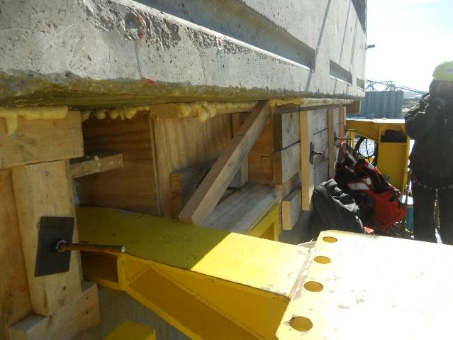


22 (2) (3) Copyright 2015 John E. Kristensen Page 22 of 38


23 (4) (5) Closure pours may be needed periodically through the erection to correct any unaccounted field conditions, this will help ensure errors won t be cumulative through the structure. If line can be maintained through minor shimming, these intermediate closures will not be necessary and can be closed with the end pours of the span. If the table-top is aligned within tolerances, start erecting subsequent segments otherwise, use a closure pour at this point to make corrections (this is the easiest point to make corrections to project the correct line and grade through the span). Closure pours will require a means to temporarily hang the segments in place until cast in place concrete can be formed and poured in the closure. Once all adjustments are made for line and grade, typical erection can proceed. Copyright 2015 John E. Kristensen Page 23 of 38

 Lift the cantilevered segments and hang them from the strongbacks. (3) Using the geometry control data from the segment casting yard, adjust the two segments to the correct line and grade.")
24 Since the pier segments have been fixed to the substructure any alignment issues in the substructure will be carried into the superstructure making a closure pour necessary. When this happens, strongbacks will be needed to temporarily hang the first cantilevered segments in place until the closure pour concrete cures and the temporary post-tensioning can be stressed to make the segments self-supporting in their cantilevered position. The sequence is as follows: (1) Using high strength threaded rods, anchor the strongbacks to the pier segments. (2) Lift the cantilevered segments and hang them from the strongbacks. (3) Using the geometry control data from the segment casting yard, adjust the two segments to the correct line and grade. (4) Form and place the closure pour between the segments (make sure stressing and grouting embeds are in place and sealed). (5) Once the concrete has attained the required strength, high strength threaded rod will installed through the segments and tensioned to provide the compressive load required for erection, and at this point if the design requires, cantilever tendons will be installed and stressed in the top flange of the segment. The pictures correspond to the numbered steps above. (2) Copyright 2015 John E. Kristensen Page 24 of 38


25 (4) (5) At this point, the table top is complete, self-supporting, and set to the correct line and grade. The typical balanced cantilevered erection can begin. Copyright 2015 John E. Kristensen Page 25 of 38

26 Erection Geometry Geometry Control for the erection process is necessary to ensure that the segments of the spans are oriented in the correct horizontal and vertical alignments, as well as, control for cross slope super-elevations. In addition to the geometry control needed for the bridge design alignment, the balanced cantilever erection method requires additional geometry control to account for the temporary construction loads on the structure caused while the span is in the cantilevered condition. Additional camber must be built into the segments. This camber will flatten out as the cantilever lengths increase. The segments are surveyed and placed in their as-cast alignment, then adjusted for any field conditions that deviate. The erection should follow the values ascast. Minor deviations should be expected and are easily adjusted. More severe adjustments may occur and should be addressed by the engineer on a case-by-case basis. In order to understand the geometry control for erection, a brief overview of the casting geometry is necessary (for further detail a subsequent course will detail the casting geometry more in-depth). For this course the precast segments will be short-line Copyright 2015 John E. Kristensen Page 26 of 38
27 match-cast. This means the segments are cast sequentially in a single stationary form system where subsequent segments are cast against their predecessor creating a matching pair. The exact bridge geometry is established between the matched pairs such that the segment is unique to a singular place in the structure. The controlled setting of the precast yard allows production similar to an assembly line environment with the goal of completing a segment each day per cell. After casting a segment, the previous day s production is asbuilt by the survey crews to ensure the geometry was maintained while the concrete set. If the asbuilt survey shows any deviation from the plan geometry, adjustments will be made in the subsequent castings the correct the error (minor deviations can be corrected in the next segment while more severe differences may take several segments to span the adjustment or may ultimately result in rejection of the segment making a re-cast necessary). The segment is rolled out of the forms and then set in the match-cast position for the next placement. The forms are tightened around the match-cast segment, embedded materials are placed, and the new geometry is surveyed to make the segment ready for concrete. The procedure is repeated with the match-cast segment rolled out to storage, the casting rolled out to be the new match-cast, and the cell prepared for a new casting. The as-cast survey is recorded to be given to the field surveyors at the erection site for controlling the erection alignment. At erection the individual segments are surveyed as they are placed in the cantilevered position, then the deck is re-surveyed as a unit to confirm the alignment was maintained through the erection process. Utilizing the survey control points cast into the segment, the first segment will be set in the required location and the following segments will be surveyed as they are placed to aid the fitting up of the matching pairs. The geometry will be monitored with each segment placed and compared to the recorded data from the casting. Through the erection process minor changes due to field tolerances will occur. This can be controlled by adding cast-in-place closure pours between segments (usually at planned locations at the beginning, end, and midpoint segments of the span but additional closures (designed condition or field condition) are possible). Since the closures are cast-in-place, the geometry can be adjusted horizontally and vertically to accommodate transverse and longitudinal changes (further options are discussed in the typical segment erection section). Copyright 2015 John E. Kristensen Page 27 of 38
 Place epoxy on match-cast faces (epoxy acts as a lubricant and sealer to facilitate a")
28 Balanced Cantilever Erection As with other segmental bridge erection methods, the typical segment erection is a repetitive process that gains efficiency with experience and scale. Basic steps for erecting the individual elements of the span, alternating from upstation to downstation: (1) Place epoxy on match-cast faces (epoxy acts as a lubricant and sealer to facilitate a tight fit between segments), (2) Raise balanced segments along respective sides of previous segments, (3) Connect high strength rods between segments, (4) Stress rods to provide epoxy squeeze to seat the segments to their match-cast (any epoxy that oozes or drips out during the squeeze will need to be cleaned) (check the post-tensioning ductwork for epoxy that squeezes into the duct and restricts the diameter) at the end of this step the segments are self-supporting, (5) Install cantilever post-tensioning tendons in the internal ductwork of the balanced Copyright 2015 John E. Kristensen Page 28 of 38
, (7) At this time the ducts for the rods and tendons can be")
 Check survey control for line and grade to")
 Repeat procedure to complete the")

29 segment pair s top slab (post-tensioning for cantilevered state are in top slab, continuity tendons for span completion are in the bottom slab), (6) Stress tendons and measure elongations (discussed in stressing and grouting section), (7) At this time the ducts for the rods and tendons can be grouted but this is a time consuming step and may cause problems if the grout leaks over into future ductwork ( grout migration ). Access should be provided to grout the post-tensioning elements after the span is fully erected, (8) Check survey control for line and grade to control plumbness and rotation (geometry programs should account for erection cambers cast into the segments for cantilever), (9) If survey shows any signs of deviation from the as-cast geometry the next segment will need shimming to correct the error, (10) Repeat procedure to complete the cantilever span, (11) Cast closure pours at mainspan and backspan connections, (12) Install, stress, and grout interior and exterior continuity post-tensionings. At this point the span will no longer be cantilevered and will be a continuous span through supports. Copyright 2015 John E. Kristensen Page 29 of 38

 but remember twists in one direction")
30 Prior to making the final closure pours (both midspan and backspan) alignment issues can develop that cannot be corrected by shimming. In this case the cantilever tips will need to be secured and brought into alignment using strongbacks. The strongbacks are used to stabilize the cantilever ends, hang formwork and access scaffolding, and vertically align the tips. For horizontal corrections cross chains and come-alongs can bring the tips into alignment (cantilevers on bearings will correct easier than fixed column types) but remember twists in one direction will cause an equal and opposite twist at the balanced end of the cantilever. The following pictures show (1) The midspan gap between two balanced cantilevers, (2) lifting the final segment into the gap with the strongback frame assembly partially installed above, (3) Overhead view of final segment being lifted into place (note ductwork connections of the continuity post-tensioning in the bottom slab, (4) strongbacks holding final segment in place while formwork for closure pours are installed (note strongbacks are adjusted with allthread rod to align the segments vertically and a diagonal cable with a come-along aligns the tips horizontally), (5) Final segment hanging in place. Copyright 2015 John E. Kristensen Page 30 of 38


31 Copyright 2015 John E. Kristensen Page 31 of 38

32 As previously stated, while the segments are being erected epoxy is applied to the match cast faces. The epoxy is used as a lubricant/sealant to aid construction and increase long term durability of the structure. When pressure is applied with temporary high strength rods for an epoxy squeeze to seal the joints the excess epoxy will be forced out of the joint from the compressive load. Copyright 2015 John E. Kristensen Page 32 of 38
.")
33 If the span is over live traffic, private property, or environmentally sensitive areas, it is a good idea to drape netting below each joint to catch the epoxy that drips from the squeeze so it won t damage anything below while it hardens (once hardened it is inert and based on owners criteria, can be left behind). If the underside of the bridge has an architectural requirement, the drips will need to be cleaned off each joint or they will harden into unwanted jagged stalactites. If too much epoxy is used on the joints, excessive amounts will squeeze out as the joints are pulled tightly together. This will affect the amount of epoxy purchased, handled, and cleaned up. If too little epoxy is used, the joints will leak which will require epoxy pressure injection sealing to repair the integrity of the corrosion/freeze/thaw protection systems. The optimal amount of epoxy per joint will be fine-tuned by experience as spans are completed. Simple formwork elements are hung between the two segments and held in place with all-thread rods for a tight seal. High Early concrete is usually used when making a closure pour to minimize curing time to obtain the minimum compressive strength and continue operations. Copyright 2015 John E. Kristensen Page 33 of 38


34 Spreading epoxy lubricant/sealer between segments prior to tensioning Forming closure pours from interior of segment box Copyright 2015 John E. Kristensen Page 34 of 38


35 Lastly the final postensiong materials are installed through internal and external ductwork in the span interior. Continuity tendons in the bottom flanges are accessed through blisters formed in the floor slab of the box interior. Once stressed these tendons provide the uplift forces needed for the newly completed simple span. Copyright 2015 John E. Kristensen Page 35 of 38
 occurs after the span is complete.")
36 Stressing and Grouting The temporary rod post-tensioning and permanent strand tensioning operations (cantilevered tendons in the top flange) are performed as each segment is hung from the cantilevered ends. Permanent internal and external strand and rod post-tensioning (continuity tendons in the bottom flange) occurs after the span is complete. Install posttensioning strand and rod longitudinally through the span. The number of strands per duct and the number of ducts per span will vary and a stressing sequence will be provided in order to transfer a uniform load. The strand is stressed using high strength hydraulic jacks. When the jacks reach the required pressure (compressive loads will be calculated in terms of hydraulic pressure in the jacks) the strands will be anchored in places with wedges to retain the loaded energy. The stresses applied to the strand will stretch the steel. Elongations will be measured to ensure the stresses occurred over the entire length of the strand (a shortened elongation will mean the strand is pinched somewhere along its length and repairs may be necessary). The ducts are then pressure grouted to both Copyright 2015 John E. Kristensen Page 36 of 38

37 protect the strand from corrosion and to permanently contain the stresses from the jacks. Concrete is then poured around the anchor blocks for further corrosion protection. Stressing and Grouting operations are explained in more detail in the Suncam course Precast Segmental Bridge Construction Stressing and Grouting. Once each span is complete it will be capable of being open to traffic for the design loading. No matter how accurate the geometry control is with casting and erecting the superstructure elements, the riding surface will be constructed by the individual segments and will reflect any imperfections across each segment joint. This will not matter for railway bridges or other structures where the segments are not the final riding surface. For bridges with rideability requirements, a longitudinal grinding is Copyright 2015 John E. Kristensen Page 37 of 38
38 recommended to eliminate these imperfections and a transverse grooving can be added to improve skid resistance. Summary Conclusion This course is gives a more specific look at the Balanced Cantilever Method of superstructure erection for precast segmental bridges, broader information can be found in the Suncam course Precast Segmental Bridge Construction An Introduction. This construction is very specialized and no matter how in-depth the courses are written there is no substitute for experience. Many specialty subcontractors and suppliers offer onsite consulting services as a supplement to the construction staffing. To organize a new construction project, managers should strongly consider these additions as well as the support of an experienced construction engineering firm. The consulting experience will help train the project personnel, troubleshoot problems, and give confidence to the owner. Additionally, a well-structured quality control program is a must. From design to casting to erection, unaccounted errors can have significant impacts to cost, schedule, and SAFETY. Lastly, safety must be a constant focus of every operation. Because of the versatility of these bridges (mostly described in the opening paragraphs of the course) they are often chosen to be constructed in some of the most adverse and inaccessible areas imaginable. Working with extreme weights at excessive heights requires safety diligence from every stakeholder. A comment from a past superintendent demanding patience about an operation; we re not just throwing pillows around, sounds lighthearted considering the critical nature of these operations but served as a rallying cry for the safety of an entire project that completed without any OSHA recordable or lost-time incidents. Please be safe. Copyright 2015 John E. Kristensen Page 38 of 38
Precast Segmental Bridge Construction Part 2 - Span by Span Erection Method
 Precast Segmental Bridge Construction Part 2 - by John E. Kristensen PE., PLS., PMP. Introduction The popularity of precast concrete segmental bridge construction has grown worldwide in the last few decades.
Precast Segmental Bridge Construction Precast Segment Manufacturing
 Precast Segmental Bridge Construction Precast Segment Manufacturing by John E. Kristensen PE., PLS., PMP. Introduction The popularity of precast concrete segmental bridge construction has grown worldwide
Precast Segmental Bridge Construction Part 1 - An Introduction
 Precast Segmental Bridge Construction Part 1 - An Introduction by John E. Kristensen PE., PLS. Introduction The popularity of precast concrete segmental bridge construction has grown worldwide in the last
Design and Construction of the SH58 Ramp A Flyover Bridge over IH70. Gregg A. Reese, PE, CE, Summit Engineering Group, Inc.
 Design and Construction of the SH58 Ramp A Flyover Bridge over IH70 Gregg A. Reese, PE, CE, Summit Engineering Group, Inc., Littleton, CO ABSTRACT: The SH58 Ramp A bridge in Golden, CO is the latest on
Bonner Bridge Replacement Update:
 Bonner Bridge Replacement Update: Jerry D. Jennings, PE - NCDOT Division 1 Engineer Pablo A. Hernandez, - NCDOT Resident Engineer September 18, 2017 Bonner Bridge Replacement Timeline Refresher Bonner
SPECIAL SPECIFICATION 4584 Segmental Concrete Bridge Unit
 2004 Specifications CSJ: 0028-09-111 SPECIAL SPECIFICATION 4584 Segmental Concrete Bridge Unit 1. Description. Construct cast-in-place segmental concrete box girder superstructure according to the plans,
PROJECT UPDATE SOUTH NORFOLK JORDAN BRIDGE CITIES OF PORTSMOUTH AND CHESAPEAKE, VIRGINIA. April 2012
 PROJECT UPDATE Rendering View from the City of Chesapeake Elizabeth River Boat Landing and Park looking across the Elizabeth River at Portsmouth CITIES OF PORTSMOUTH AND CHESAPEAKE, VIRGINIA The new 5,375
VIADUCTS BY PUSHING: INCREMENTALLY LAUNCHED BRIDGES
 Istanbul Bridge Conference August 11-13, 2014 Istanbul, Turkey VIADUCTS BY PUSHING: INCREMENTALLY LAUNCHED BRIDGES J. E. Erdoğan 1 and Ö. Özkul 2 ABSTRACT Despite its widespread use around the world, constructing
BRIDGE CONSTRUCTION USING SELF-PROPELLED MODULAR TRANSPORTERS (SPMT)
") SPECIAL PROVISION August 31, 2009 PROJECT # S-R399(42) PROJECT # S-R399(59) PIN # 6697/7236 SECTION 03253S BRIDGE CONSTRUCTION USING SELF-PROPELLED MODULAR TRANSPORTERS (SPMT) Add Section 03253S: PART
SPECIAL PROVISION August 31, 2009 PROJECT # S-R399(42) PROJECT # S-R399(59) PIN # 6697/7236 SECTION 03253S BRIDGE CONSTRUCTION USING SELF-PROPELLED MODULAR TRANSPORTERS (SPMT) Add Section 03253S: PART
Bridge Construction Methods
 Bridge Construction Methods Mr. K F TAM, MHKIE, MCIHT Gammon Construction Limited Abstract In Hong Kong, bridge is one of the main transportation accesses. Gammon has responded with resourcefulness, innovation
Concrete Bridge Design and Construction series
 www.thestructuralengineer.org 41 CBDC series July 2014 Concrete Bridge Design and Construction series This series is authored by the Concrete Bridge Development Group (CBDG). The group aims to promote
Garage Beam System DAYTONSUPERIOR.COM FORMING. For Post-Tensioned Beam and Slab Parking Structures
 Garage Beam System For Post-Tensioned Beam and Slab Parking Structures FORMING The Garage Beam System is a complete forming system designed specifically for post-tensioned beam and slab multi-story parking
PRECAST CONCRETE GIRDER ERECTION
 7.1 Precast Concrete Girder Erection - General Erection of precast concrete girders includes transporting the girders to the site, handling and temporary storage, installing anchor bolts, shear blocks
MARTA Rapid Transit Bridges
 MARTA Rapid Transit Bridges his precast segmental post-tensioned concrete project for the T Metropolitan Atlanta Rapid Transit Authority demonstrates the ability of the segmental technique to economically
SINGLE STEEL BOX GIRDER BRIDGES FOR THE TERMINAL DEVELOPMENT PROJECT AT TORONTO PEARSON INTERNATIONAL AIRPORT. Srdjan Brasic, M.Sc., P.Eng.
 SINGLE STEEL BOX GIRDER BRIDGES FOR THE TERMINAL DEVELOPMENT PROJECT AT TORONTO PEARSON INTERNATIONAL AIRPORT Srdjan Brasic, M.Sc., P.Eng. UMA Engineering Ltd. Paper prepared for presentation at the Technical
CONSTRUCTABILITY IMPROVEMENT OF BRIDGES USING STEPPING FORMWORK
 CONSTRUCTABILITY IMPROVEMENT OF BRIDGES USING STEPPING FORMWORK By Mohamed Emam Abd El-Razek, 1 and Ismail M. Basha 2 ABSTRACT: Many construction systems have been used to build several highway bridges
Concrete Prestressed Concrete Pretensioned Concrete Posttensioned Concrete Typical Tendon Layout
 Concrete 45 1.13.0 Prestressed Concrete Concrete in which internal stresses (forces) are induced by means of prestressing steel tendons such that tensile stresses resulting from loads are counteracted
Florida DOT efforts toward improving Post Tension Durability
 Florida DOT efforts toward improving Post Tension Durability By William Nickas 1 (C) COPYRIGHT POST-TENSIONING INSTITUTE, ALL RIGHTS RESERVED Page 1 of 73 Post-Tensioning Strategies Enhanced PT Systems
Ironton Russell Bridge Project
 Construction Update July 1, 2015 Rendering by URS Responsible for Construction Inspection & Engineering Prepared by: Brian Davidson, P.E. Project Overview The entails the construction of a cast in place
Installation Manual. ArchCast Bridge. 3-Sided Precast Concrete Bridge Structure
 ArchCast Bridge 3-Sided Precast Concrete Bridge Structure Installation Manual Salem Location: 749 West Commercial Ave. Salem, IL 62881 (618) 548-1190 countymaterials.com Email: info@countymaterials.com
2016 ACEC/PA ANNUAL MEETING
 2016 ACEC/PA ANNUAL MEETING z I-49 North, Segment K (I-220 to Martin Luther King Drive) Interchange Project Durk Krone, P.E., TRC Engineers Inc., Baton Rouge, La 1 I-49 North Segment K Project 2 AGENDA
WALL CANTILEVER WORK STATION JIB CRANE
 SECTION 14662 WALL CANTILEVER WORK STATION JIB CRANE ***** Gorbel, Inc. manufactures a broad range of material handling cranes including monorail, bridge, gantry, and jib cranes. Numerous work station
NSBA. Prize Bridge. Awards
 NSBA 2016 Prize Bridge Awards THE COUNTRY S BEST STEEL BRIDGES have been honored in this year s Prize Bridge Awards competition. Conducted every two years by the National Steel Bridge Alliance (NSBA),
Displayed with permission The American Surveyor October Copyright 2008 Cheves Media
 trains vancouver for olympic games precision alignment aids expanded transit system >> By Vicki Speed Launching girders, positioned well above the busy highways below, are set to begin construction of
1. Cast-in-place concrete is specified in Section
 SECTION 03 38 00 PART 1 - GENERAL 1.01 DESCRIPTION A. This Section describes the requirements for furnishing and installing post-tensioned slabs, jacks, jacking and anchors at Parking Structure, and record
Principal Bridge Engineer Middle East & India Atkins Abu Dhabi, UAE
 Design of continuity slabs and the 020 Gajanan Chaudhari Principal Bridge Engineer Middle East & India Atkins Abu Dhabi, UAE Anand Panpate Senior Bridge Engineer Middle East & India Atkins Abu Dhabi, UAE
Ironton Russell Bridge Project
 Construction Update January 1, 2016 Rendering by URS Responsible for Construction Inspection & Engineering Prepared by: Brian Davidson, P.E. Project Overview The Ironton Russell Bridge Project entails
Long Railway Viaducts with Special Spans: Part-1. Arch Construction by Balanced Cantilever with Auxiliary Cables
 Long Railway Viaducts with Special Spans: Part-1. Arch Construction by Balanced Cantilever with Auxiliary Cables J. Manterola A. Martínez Carlos Fernández Casado S.L., Spain B. Martín J.A. Navarro M. A:
The Hashemite University Department of Civil Engineering. Dr. Hazim Dwairi. Dr. Hazim Dwairi 1
 Department of Civil Engineering Lecture 2.1 Methods of Prestressing Advantages of Prestressing Section remains uncracked under service loads Reduction of steel corrosion (increase durability) Full section
JFK Airport Light Rail Transit System
 JFK Airport Light Rail Transit System Author: Co-Author: Company: José M. Rodriguez, P.E., Senior Project Director D. Brice Urquhart, P.E., Project Manager Figg Bridge Engineers, Inc. Address: 424 N. Calhoun
Construction of Bridges
 Construction of Bridges Materials suitable for the Construction of Long-span Bridges 1. Stone in arch masonry 2. Steel in girder or box-section constructed in steel plates and standard sections 3. Steel
SPECIFICATIONS FOR ERECTION OF PRECAST PRESTRESSED CONCRETE GIRDERS
 SPECIFICATIONS FOR ERECTION OF PRECAST PRESTRESSED CONCRETE GIRDERS 1.0 DESCRIPTION The Work shall consist of:.1 Transportation, unloading, and erection of precast prestressed concrete girders;.2 Supply
CASE STUDY OF LONG SPAN STEEL BRIDGE STABILITY DURING DESIGN AND CONSTRUCTION
 CASE STUDY OF LONG SPAN STEEL BRIDGE STABILITY DURING DESIGN AND CONSTRUCTION KEVIN D. SEAR, PE SUSAN STEELE, PE BIOGRAPHY Kevin Sear has been a structural engineer for over 42 years, the first 10 years
Elevated Slab Sequence
 Elevated Slab Sequence The following group of photos shows the sequence for installa4on of a one- way elevated slab. (Slab & Beam with Reinforcing & Post- Tensioning) Columns Placed & Form Support (Scaffolding)
Lecture 13 CONCRETE WORKS
 Lecture 13 TSP-308 MPK Ferdinand Fassa CONCRETE WORKS Concrete works Concrete is a man-made (rock) construction material, which is a mixture of portland cement, water, aggregates, and in some cases, admixtures.
Bridge articulation No. 1.04
 Bridge articulation Scope This Guidance Note gives advice on the selection of the articulation arrangements, the choice of bearing types and dispositions of bearings, for bridges where relative movement
SPECIFICATIONS FOR INSTALLATION OF PRECAST PRESTRESSED CONCRETE DECK PANELS
 SPECIFICATIONS FOR INSTALLATION OF PRECAST PRESTRESSED CONCRETE DECK PANELS 1.0 DESCRIPTION The Work shall consist of:.1 Transportation, unloading, erection and grouting of precast prestressed concrete
Precast Prestressed Segmental Elevated Urban Motorway in Italy
 Precast Prestressed Segmental Elevated Urban Motorway in Italy Bruno Gentilini Lino Gentilini Consulting Engineers Trento, Italy Bruno Gentilini Lino Gentilini The authors, who were responsible for the
Ironton Russell Bridge Project
 Construction Update October 1, 2014 Rendering by URS Responsible for Construction Inspection & Engineering Prepared by: Brian Davidson, P.E. Ironton Russell Bridge Project Project Summary: October 1, 2014
Ironton Russell Bridge Project
 Construction Update March 1, 2014 Rendering by URS Responsible for Construction Inspection & Engineering Prepared by: Brian Davidson, P.E. Ironton Russell Bridge Project Project Summary: March 1, 2014
Installation and Maintenance Manual for EMH Freestanding Workstation Jib Cranes
 1 Installation and Maintenance Manual for EMH Freestanding Workstation Jib Cranes Installation and Maintenance Manual for EMH Freestanding Workstation Jib Cranes Table of Contents Forward.... 3 Mast Installation...
Long Key Bridge, a spectacular example. Design Features and Prestressing Aspects of Long Key Bridge
 Design Features and Prestressing Aspects of Long Key Bridge { i Thomas M. Gallaway* Principal Cutler-Gallaway Services, Inc. Consulting Engineers San Antonio, Texas Long Key Bridge, a spectacular example
STRUCTURAL CONCRETE - LIGHTWEIGHT
 SPECIAL PROVISION May 27, 2010 Add Section 03312: PROJECT #MP-I15-6(178)245 PIN #7037 SECTION 03312S STRUCTURAL CONCRETE - LIGHTWEIGHT PART 1 GENERAL 1.1 SECTION INCLUDES A. Materials and procedures for
Tilikum Crossing Transit Bridge. Portland, OR
 Tilikum Crossing Transit Bridge Portland, OR Technical Information Size of Project: The Tilikum Crossing Transit Bridge is 1,720 ft. long and required 24,000 cy total concrete Strength Requirements: The
Ironton Russell Bridge Project
 Construction Update September 1, 2014 Rendering by URS Responsible for Construction Inspection & Engineering Prepared by: Brian Davidson, P.E. Ironton Russell Bridge Project Project Summary: September
LAYING OUT THE OVERHEAD CONVEYOR SYSTEM
 LAYING OUT THE OVERHEAD CONVEYOR SYSTEM Following is a step by step guide that is offered as just that, a guide, and is not intended to be an engineering manual. For a well engineered overhead conveyor
Dr. Ahmed Hussien Elyamany 2017 Questions
 Questions Question 1 (25 Marks): Select the best answer from the available choices for each of the following: 1. Cranes may be used for 2. cranes consist of a carrier and superstructure equipped with a
Smarter. Safer. Leaner.
 Smarter. Safer. Leaner. Fast Installation and Removal Decrease Leading Edge Exposure by 87% OSHA Compliant Versatile and Reusable Use Perimeter Protection Posts During Construction: At Building Perimeter
TECHNICAL SPECIFICATION
 TECHNICAL SPECIFICATION ITEM 03100 CONCRETE FORMWORK 1.0 GENERAL 1.1 DESCRIPTION This section defines requirements and limitations for design, construction, erection, and removal of concrete formwork for
This guide can be used to prepare a specification for incorporating free standing jib cranes into a competitively bid construction project.
 SECTION 14651 FREE STANDING JIB CRANE ***** Gorbel, Inc. manufacturers a broad range of material handling cranes including monorail, bridge, gantry, and jib cranes. Numerous work station and industrial
Progressive Erection Applied to Box Girder with Strutted Wing Slab
 Progressive Erection Applied to Box Girder with Strutted Wing Slab Koji Osada 1, Taketo Kanamoto 1, Kimito Saito 2, Takahiro Arai 2 1 Introduction The Uchimaki Viaduct is a multi-span continuous box girder
KEYWORDS: Barge Stability, Steel Truss Erection, Horizontal Sliding of Steel Trusses
 Replacement of the BNSF Approach Spans over the Mississippi River DAVID ROGOWSKI, P.E. AND JOSH CRAIN, Genesis Structures Inc., Kansas City, Missouri and DAN SIEVE AND KEVIN BECKER, Walsh Construction
Grade Separation Systems. Single-Span Rail Bridge Construction Procedure. An innovation from art engineering inc.
 Grade Separation Systems Single-Span Rail Bridge Construction Procedure An innovation from art engineering inc. GSS Single-Span Example Shown: An existing railroad grade crossing. Existing railroad Existing
1/26/2015 DETAILS CIP DETAIL EXAMPLES WHY SIMPLIFY DETAILS? CIP DETAIL EXAMPLES DETAILING FOR SIMPLICITY
 Detailing of ABC Bridges for Simplicity and Durability Michael P. Culmo, P.E. CME Associates, Inc. East Hartford, CT DETAILS This presentation contains many preferred details My favorite details will be
Symons Soldier DAYTONSUPERIOR.COM FORMING. Versatile Soldier Beam System
 Symons Soldier Versatile Soldier Beam System FORMING The Symons Soldier system is a lightweight, yet extremely strong, construction beam system that is adaptable to almost any forming or shoring configuration
Steve Haines, P.E., Parsons, (303) , James Studer, Kiewit, (926) ,
 , James Studer, Kiewit, (926) ,") PLACEMENT OF PRECAST PRESTRESSED CONCRETE GIRDER BRIDGE SPANS WITH SELF PROPELLED MODULAR TRANSPORTERS PIONEER CROSSING DESIGN/BUILD PROJECT, AMERICAN FORK, UT Steve Haines, P.E., Parsons, (303) 831-8100,
PLACEMENT OF PRECAST PRESTRESSED CONCRETE GIRDER BRIDGE SPANS WITH SELF PROPELLED MODULAR TRANSPORTERS PIONEER CROSSING DESIGN/BUILD PROJECT, AMERICAN FORK, UT Steve Haines, P.E., Parsons, (303) 831-8100,
STANDARDIZED CONCRETE BRIDGES IN TEXAS. John Holt, PE, Texas Department of Transportation Ronald Medlock, PE, Texas Department of Transportation
 STANDARDIZED CONCRETE BRIDGES IN TEXAS John Holt, PE, Texas Department of Transportation Ronald Medlock, PE, Texas Department of Transportation ABSTRACT Standardized concrete bridge plans are used extensively
PRESTRESSED CONCRETE STRUCTURES. Amlan K. Sengupta, PhD PE Department of Civil Engineering Indian Institute of Technology Madras
 PRESTRESSED CONCRETE STRUCTURES Amlan K. Sengupta, PhD PE Department of Civil Engineering Indian Institute of Technology Madras Module 01: Introduction, Prestressing Systems and Material Properties Lecture
Design, fabrication and construction of Railway Bridge over Södertälje canal
 NSCC2009 Design, fabrication and construction of Railway Bridge over Södertälje canal Michael B. Thulstrup 1, Mattias Nilsson 2, Robert Hällmark 3 & Jens P. Nielsen 4 1 Project Manager, MT Højgaard a/s,
MK SYSTEM. // Pieces that can be easily assembled with minimal tools. Numerous configurations with standard components
 MK SYSTEM Numerous configurations with standard components // Pieces that can be easily assembled with minimal tools // Table of contents Product description MK Systems Basic components MK SYSTEM product
Lesner Bridge Replacement
 Lesner Bridge Replacement Rendering of the Completed Lesner Bridge Structure Construction Camera A Construction Camera has been installed to view images of the bridge construction. Images are updated on
TILT-UP PRECAST CONCRETE SANDWICH PANELS. A. Work includes, but is not limited to, the following:
 PART 1 GENERAL 1.01 SUMMARY SECTION 03460 TILT-UP PRECAST CONCRETE SANDWICH PANELS A. Work includes, but is not limited to, the following: 1. Architectural precast concrete sandwich wall panels. 2. Integral
PHASING CONSIDERATIONS FOR BRIDGES
 PHASING CONSIDERATIONS FOR BRIDGES Christopher Miller, P.E. 6/11/18 Table of contents 1 What Not to Do 3 2 Span Arrangement 4-9 3 4 5 6 Superstructure Geometric Considerations Superstructure Structural
***************************************************************************************************************
 03365 POST-TENSIONED CONCRETE *************************************************************************************************************** SPECIFIER: CSI MasterFormat 2004 number 03 38 00. ***************************************************************************************************************
Lesner Bridge Replacement
 Lesner Bridge Replacement Rendering of the Completed Lesner Bridge Structure Construction Camera A Construction Camera has been installed to view images of the bridge construction. Images are updated on
SECTION TILT-UP PRECAST CONCRETE SANDWICH PANELS. A. Work includes, but is not limited to, the following:
 PART 1 GENERAL 1.01 SUMMARY SECTION 03460 TILT-UP PRECAST CONCRETE SANDWICH PANELS A. Work includes, but is not limited to, the following: 1. Architectural precast concrete sandwich wall panels. 2. Integral
US-131 Over the Muskegon River. Corey Rogers, P.E. Bridge Construction Engineer
 US-131 Over the Muskegon River Corey Rogers, P.E. Bridge Construction Engineer NB and SB US-131 Each bridge is a three-span, 580 foot long, cast-in-place, post-tensioned concrete box girder structure resting
The construction technology of Chongqing Chaotianmen Bridge
 The construction technology of Chongqing Chaotianmen Bridge Zhongfu Xiang School of Civil Engineering & Architectures, Chongqing Jiaotong University, Chongqing, China Wei Xu China zhongtie major bridge
AREMA 2008 Annual Conference. LOW PROFILE RAILROAD BRIDGE Steve K. Jacobsen, PE NNW, Inc. Rochester, Minnesota
 AREMA 2008 Annual Conference LOW PROFILE RAILROAD BRIDGE Steve K. Jacobsen, PE NNW, Inc. Rochester, Minnesota 55904 507-281-5188 Steve K. Jacobsen, PE 2 LOW PROFILE RAILROAD BRIDGE Steve K. Jacobsen, PE
Health & Safety Policy and Procedures Manual SECTION 23 MASONRY CONSTRUCTION
 SECTION 23 MASONRY CONSTRUCTION 1. Masonry Construction: A. Whenever a masonry wall is being constructed, a limited access zone will be established prior to construction meeting the following requirements.
Accelerated Bridge Construction in USA
 Accelerated Bridge Construction in USA Abstract Rush hour traffic is a common daily occurrence in the USA. Highway and bridge construction further aggravates the situation. The Federal Highway Administration
CONCRETE SPLICED GIRDERS IN TEXAS. Nicholas Nemec, P.E. TxDOT-BRG
 CONCRETE SPLICED GIRDERS IN TEXAS Nicholas Nemec, P.E. TxDOT-BRG October 15, 2014 What is a Concrete Spliced Girder? 2 What is a Concrete Spliced Girder? What it is NOT : Continuous For Live Load 3 What
CHAPTER 17 - SPECIALIST CONSTRUCTION SYSTEMS
 CHAPTER 17 - SPECIALIST CONSTRUCTION SYSTEMS WJ Martin 17.1 SCOPE Specialist construction systems refer to the construction systems falling outside of the normal reinforced and prestressed bridges that
INSTALLATION MANUAL FOR MODULAR EXPANSION JOINT (LG SYSTEM)
") INSTALLATION MANUAL FOR MODULAR EXPANSION JOINT (LG SYSTEM) TABLE OF CONTENTS 1. INTRODUCTION TO THE MODULAR EXPANSION JOINT 1.1 Purpose 1.2 How They Work 1.3 Movement Capacity 1.3.1 Longitudinal Direction
INSTALLATION MANUAL FOR MODULAR EXPANSION JOINT (LG SYSTEM) TABLE OF CONTENTS 1. INTRODUCTION TO THE MODULAR EXPANSION JOINT 1.1 Purpose 1.2 How They Work 1.3 Movement Capacity 1.3.1 Longitudinal Direction
Ironton Russell Bridge Project
 Construction Update October 1, 2013 Rendering by URS Responsible for Construction Inspection & Engineering Prepared by: Brian Davidson, P.E. Project Overview The Ironton Russell Bridge Project entails
The New Incremental Launching Construction Technology of Jiubao Bridge Long-span Hybrid Arch-girder Structure
 The New Incremental Launching Construction Technology of Jiubao Bridge Long-span Hybrid Arch-girder Structure C.Y. Shao Shanghai Municipal Engineering Design & Research General Institute (Group) Co. Ltd.,
Division 03 - Concrete Section New Westminister Multi-Use Civic Facility & Office Building Project No Page 1
 Project No. 210022 Page 1 PART 1 GENERAL 1.7 Documents.1 The General Conditions of the Canadian Standard Construction Document CCDC-2, together with all amendments and supplements and Division 1 General
Miami Marlins Baseball Park
 Miami Marlins Baseball Park Roof Support Track Beams Construction by Incremental Lifting Project Owner Miami Dade County General Contractor Hunt-Moss JV Frame Contractor Formworks-Baker Concrete JV Engineer
SECTION PLATE CONNECTED WOOD TRUSSES
 SECTION 06173 PLATE CONNECTED WOOD TRUSSES PART 1 GENERAL 1.01 SUMMARY A. Section Includes: 1. Shop fabricated wood trusses for roof and floor framing. 2. Bridging, bracing, and anchorage. B. Related Sections:
Movable Bridge Maintenance and Preservation
 Movable Bridge Maintenance and Preservation National Bridge Preservation Partnership Conference Orlando, Florida April 22 to 25, 2014 Stan Kaderbek, S.E., P.E. Agenda Movable Bridge Overview Structural
Concrete Bridge Design and Construction series
 42 Concrete Bridge Design and Construction series This series is authored by the Concrete Bridge Development Group (CBDG) The group aims to promote excellence in the design, construction and management
Over the years, the use of precast concrete has taken giant
 Precast Concrete Bridge Deck - Design, Transportation and Erection: A Designer s Overview Debabrata Mukherjee 1, Manju Balaji 2 1 Group Engineer, Atkins 2 Engineer, Atkins 76 Over the years, the use of
A New Precast Concrete Deck System for Accelerated Bridge Construction
 A New Precast Concrete Deck System for Accelerated Bridge Construction George Morcous 1(&), Fouad Jaber 2, and Jason Volz 2 1 University of Nebraska-Lincoln, Omaha, NE, USA 2 Nebraska Department of Roads,
Requirements for Measuring and Pricing of Structural Concrete
 Requirements for Measuring and Pricing of Structural Concrete October 2016 TRANSPORT INFRASTRUCTURE IRELAND (TII) PUBLICATIONS About TII Transport Infrastructure Ireland (TII) is responsible for managing
COLLECTIVE POSITION ON SAFE REMOVAL OF TEMPORARY BRACES
 COLLECTIVE POSITION ON SAFE REMOVAL OF TEMPORARY BRACES Published by the Tilt-Up Concrete Association Tilt-Up Concrete Association PO Box 204 Mount Vernon, Iowa 52314 (319) 895-6911 www.tilt-up.org COLLECTIVE
Appendix A Proposed LRFD Specifications and Commentary
 NCHRP Project 12-71 Design Specifications and Commentary for Horizontally Curved Concrete Box-Girder Highway Bridges Appendix A Proposed LRFD Specifications and Commentary A-1 A-2 4.2 DEFINITIONS (Additional)
StormPod Arch Installation Guide
 StormPod Arch Installation Guide xx Foundation Bed Preparation Use standard construction procedures for the construction of the bed for StormPod Modular Arch Systems. As with any construction project,
Introduction.» Demolition Concepts» Concept Design» Final Design» Construction» Health Monitoring
 Location of Project Introduction» Demolition Concepts» Concept Design» Final Design» Construction» Health Monitoring Existing Bridge» Built in 1928» 255-foot Open Spandrel Concrete Arch Bridge» 24-foot
SUMMARY SHEETS OF INTEGRAL CONNECTIONS
 APPENDIX F SUMMARY SHEETS OF INTEGRAL CONNECTIONS NCHRP 12-88 Connection Evaluations Appendix F F-1 APPENDIX F SUMMARY SHEETS OF INTEGRAL CONNECTIONS NCHRP 12-88 Connection Evaluations Appendix F F-2
Table of Contents Big expertise. Real convenience. Concrete commitment.
 Table of Contents General Shoring Safety Rules As Recommended By The Scaffolding, Shoring And Forming Institute... 1 General Guidelines... 1 Single And Independent Post Shore System Safety Rules As Recommended
MODULAR STEEL SUPERSTRUCTURES FOR ACCELERATED BRIDGE CONSTRUCTION - IOWA DOT CASE STUDIES
 MODULAR STEEL SUPERSTRUCTURES FOR ACCELERATED BRIDGE CONSTRUCTION - IOWA DOT CASE STUDIES NORM McDONALD CURTIS CARTER AHMAD ABU-HAWASH BIOGRAPHY Norm McDonald is the director of the Office of Bridges and
Ironton Russell Bridge Project
 Construction Update January 1, 2015 Rendering by URS Responsible for Construction Inspection & Engineering Prepared by: Brian Davidson, P.E. Project Overview The Ironton Russell Bridge Project entails
Structural System Design
 Structural System Design STRUCTURAL SYSTEM DESIGN DESIGN CRITERIA The primary goals and criteria governing the alternate concrete superstructure design are as follows: -maintain an open office layout,
Potential Solutions- Background: Current Designs. Potential Solutions. Goals for Design What are we concerned about?
 Potential Solutions Potential Solutions- Background: Current Designs Goals for Design What are we concerned about? Primary Goal: Get the deck on successfully Stability during deck pour Girder plumbness
Critical Structures Construction Issues
 Critical Structures Construction Issues FLORIDA DEPARTMENT OF TRANSPORTATION STATE CONSTRUCTION OFFICE Specification 1-3: Definitions Contractor s Engineer of Record Specialty Engineer CLASS OF CONTRACTOR
The Aizhai Suspension Bridge is
 INTERNATIONAL DESIGN & CONSTRUCTION: BRIDGES Mountain grown Hilly terrain contributes mightily to China bridge By Yinbo Liu, Ph.D., P.E., Guoping Chen, Shulong He and Yongjian Zhang, Ph.D. Contributing
P: F: Resi-Ply FORMING SYSTEM BY DAYTON SUPERIOR
 Resi-Ply FORMING SYSTEM BY DAYTON SUPERIOR Resi-Ply System The Resi-Ply forming system is a 1 1 thick plywood with steel backing bars designed especially for residential foundations and low industrial
Design & Seismic Detailing of Nonstandard Deep Precast Concrete Box Girders For Long Span Railroad Bridges By:
 Design & Seismic Detailing of Nonstandard Deep Precast Concrete Box Girders For Long Span Railroad Bridges By: ABSTRACT Shafi M. Sharifan, Ph.D., P.E. Wei Koo & Associates Orange, California Kosal Krishnan,
Ministry of Forests & Range
 Ministry of Forests & Range DRAWING SCHEDULE DRAWING No. / MODEL TYPE STD-EC-040-01 STD-EC-040-02 STD-EC-040-03 STD-EC-040-04 STD-EC-040-05 STD-EC-040-06 STD-EC-040-07 STD-EC-040-08 DESCRIPTION REV. DATE
This guide can be used to prepare a specification for incorporating wall bracket jib cranes into a competitively bid construction project.
 SECTION 14654 WALL BRACKET JIB CRANE ***** Gorbel, Inc. manufacturers a broad range of material handling cranes including monorail, bridge, gantry, and jib cranes. Numerous work station and industrial