Design of Geofoam Embankment for the. Steven F. Bartlett, Ph.D., P.E. Research Project Manager, UDOT
|
|
|
- Allen Phelps
- 6 years ago
- Views:
Transcription
1 Design of Geofoam Embankment for the I-15 Reconstruction Steven F. Bartlett, Ph.D., P.E. Research Project Manager, UDOT
2 I-15 Reconstruction - Quick Facts Single Largest Highway Contract t in U.S. 17 Miles of Urban Interstate $1.5 Billion Design-Build 4 Year Construction Duration (Summer 2001) 144 Bridges/Overpass Structures 160 Retaining Walls (mostly MSE Walls) 3.8 Million m 3 of Embankment Fill 100, m 3 Geofoam Embankment
3 Primary Uses of Geofoam on the I-15 Project Reduce Settlement to Protect Buried Utilities Improve Slope Stability of Embankments Rapid Construction in Time Critical Areas
4 Settlement Reduction (continued) Subsurface Profile in Salt Lake Valley CPT Tip Resistance, kpa Alluvium (m) Depth Bonneville Clay Pleistocene Alluvium Cutler Clay Soft Clay (10- mthick) 35 40
5 Settlement Reduction (continued) Settlement on I-15, Salt Lake City ( ) 11.6 m Fill Height 2.5 year duration Primary Settlement 1.4 m Settlement
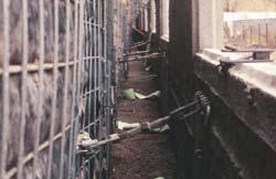
6 Settlement Reduction (continued) Buried Utilities Buried dpipeline NEW FILL Buried Pipeline Ruptured Pipeline
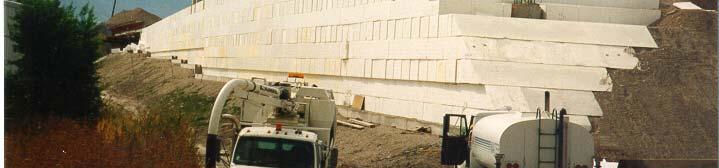
7 Settlement Reduction (continued) Buried Utilities along Roadway Buried Utilities Geofoam Embankment from State St. to 200 W. Along Interstate I-80, Salt Lake City, Utah
8 Improve Slope Stability (continued) Diagram a of Potential t Instability ty at Bridges Bridge Deck cracks Failure surface Soft Clay


9 Improve Slope Stability Details of Geofoam Construction at Bridge Abutments
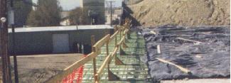
10 Rapid Construction (Typical Embankment Construction for I-15) Geotechnical Wick Drains Typical Wick Drain 1/2 SLOPE WIDTH MINIMUM NEW EMBANKMENT SHOULDER C L NEW EMBANKMENT SURCHARGE EXISTING EMBANKMENT GEOTEXTILE WICK DRAINS

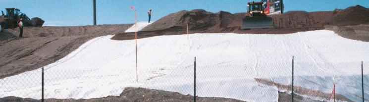


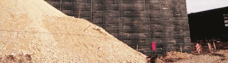
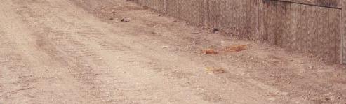

11 Rapid Construction (Typical Embankment Construction for I-15) Wick Drain Installation (4 weeks) Grading and Geotextile (4 weeks)) Wall Construction + Settlement Time (6 weeks + 24 weeks) Concrete Panel Placement (2 weeks)
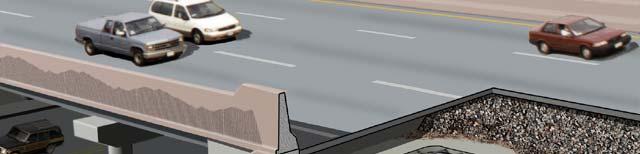
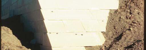
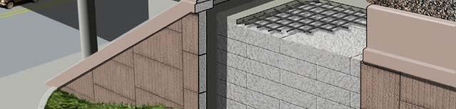
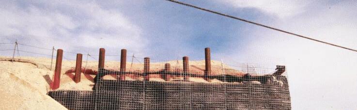
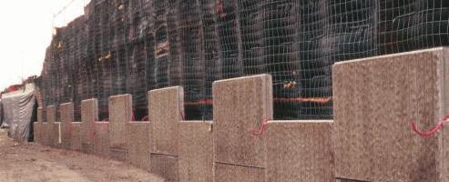
12 Rapid Construction (Typical Geofoam Construction for I-15) Tilt-up Concrete Fascia Panel Wall 35 cm Concrete Pavement 60 cm Base Material 15 cm Reinforced Concrete Load Distribution Slab Geofoam Block Sloped Embankment (1.5 H to 1 V max.) Wall Footing Bedding Sand (20 cm min.)
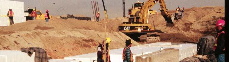
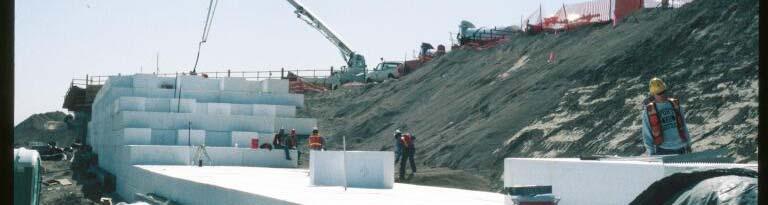
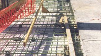
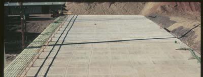
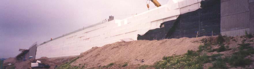
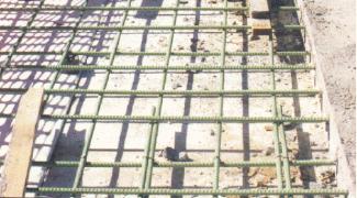

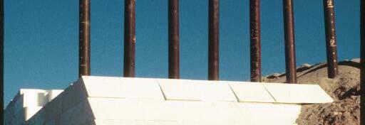
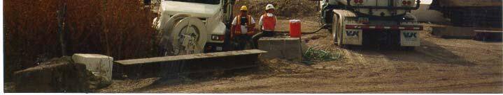
13 Rapid Construction (Typical Geofoam Construction for I-15) Grade Preparation (1 week) Block Placement (3 weeks)) Load Distribution Slab Construction (2 weeks) Panel Wall Construction (1 Week)
14 Rapid Construction (Comparison of Construction Time) Conventional 25 Geofoam Construct tion Time (Weeks) Preparation Construction Settlement Finish Work Total
15 Material Type Dimensions Density Compressive Strengthth Allowable Load & Creep Interface Friction Stability of Internal Slope Bedding Material & Compaction Concentrated Loads Moisture Absorption Buoyancy Thermal Resistance Differential Icing Chemical Attack Flammability Insect Infestation Ultra Violet Degradation Durability
16 (Material Type) Expanded Polystrene (EPS)* virgin feedstock maximum of 5 percent regrind content t * Extruded Polystrene (XPS) is also available, but was not used on the I-15 project
17 (EPS Block Dimensions) 81 cm 488 cm 122 cm Dimension tolerance 0.5 percent If tolerance is met, no trimming is necessary If tolerance is not met, shop trimming is necessary
18 (EPS Density) Property ASTM Test C 578 Type XI Type I Type VIII* Type II Type IX Nominal Density (kg/m 3 ) C303 / D Minimum Density (kg/m 3 ) C303 / D * Type VIII was used for I-15 Reconstruction
19 (EPS Minimum Compressive Strength) Property ASTM Test Type XI Type I Type VIII Type II Type IX kpa (10% Strain) C 165 / D * * Type VIII was used for I-15 Reconstruction Strain Rate for Testing = 5 mm / minute
20 (EPS Minimum Compressive Strength Versus Density) (Source: Bartlett et al. 2000) d = 7.3 * D - 47 where D = Density in kpa.
21 (Allowable Stress and Creep) Source: Negussey (1997) Type VIII EPS d = 5% strain 0.4 d * Allowable Stress Must Maintained Below 1% Axial Strain to Minimize Long-Term Creep Simplified Formula: Allowable Stress = 0.4 d Allowable Stress = 0.4 x 120 = 48 kpa
22 (Allowable Stress and Creep) Allowable Stress (Dead Load + Live Load) < 0.4 d Dead Load = Weight of Load Distribution Slab + Weight of Base Material + Weight of Pavement. Dead Load = 30 % of d = 0.3 d Live Load = Traffic Loads Live Load = 10 % of d = 0.1 d
23 (Creep Data from Norway) Measured Data (3.5 years) Theoretical Model (Source: Aaboe, 2000)


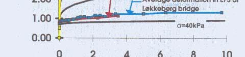
24 (Creep Data from Norway) Theoretical Model (Source: Aaboe, 2000)
25 (Interface Friction) n Lateral Force EPS BLOCK Interface Friction Need for Design Against Sliding = n tan = sliding shear resistance n = normal stress tan (Design Value) degrees (Design Value)
26 (Interface Friction) Design Value = 31 deg. Source: Negussey (1997)
27 (Stability of Internally Sloped Embankments) Back Slope 1.0 Vertical 1.5 Horizontal Maximum Back kslope = Ht to Vertical for Embankment to Guarantee Internal Slope Stability Force = 0 (Do Not Allow Transfer of Horizontal Force)


28 (Stability of Internally Sloped Cuts and Hillsides) Reinforced Slope Soil Nails, Soil Anchors, or Other Reinforcement Cut Slope or Cut Slope or Landslide
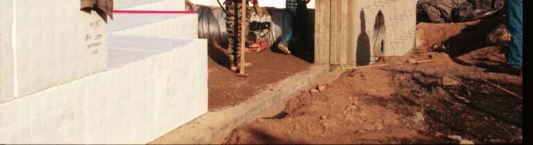
29 (Bedding Material and Compaction) Bedding Sand Function free draining sand or fine gravel provides leveling course provides drainage Bedding Sand (20 cm min.)
30 (Bedding Material and Compaction) Gradation Specification for Bedding Sand Sieve Size 50mm 13mm 6mm 2mm 0.425mm mm % Passing (Percent Passing) * Materials with more than 20 percent of the samples containing between5 and 7 percent minus mm material shall not be accepted for use.


")
31 (Bedding Material and Compaction) Grade Preparation and Leveling (*Maximum lift thickness = 20 cm) Light-Weight Compaction Equipment


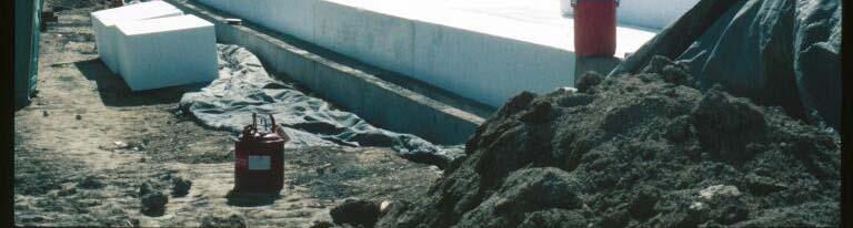
32 (Concentrated Loads) Uncovered geofoam damages easily from tire loads Do not use heavy equipment atop geofoam until the load distribution slab is placed Use light-weight g construction equipment Protect with plywood sheeting
33 (Moisture Absorption - Above High Groundwater Elevation) (Source: Aaboe, 2000)
34 (Moisture Absorption - Below Groundwater) (Source: Aaboe, 2000)
35 (Moisture Absorption - Design Values) Installation of EPS above high groundwater Design Moisture Content = 1 percent by volume Installation of EPS that is periodically submerged Design Moisture Content = 5 percent by volume Installation of EPS below groundwater Design Moisture Content = 10 percent by volume
36 (Buoyancy) 100-year design flood event F resisting F uplift groundwater Drainage Sand F resisting = 1.3 x F uplift

.")
37 (Thermal Resistance) (Negussey, 1997) R-value = heat flow through a unit width of material. R-value for geofoam is about 4 (18 kg/m 3 density). R-value for soil and concrete is less than 1.
38 (Differential Icing -Cold Regions only) No Icing pavement soil Icing EPS Good Heat Transfer Poor Heat Transfer Base material has heat capacity and prevents pavement from icing as rapidly. No Icing 60 mm base (min.) Proper Design to Prevent Icing
39 (Chemical Attack) Solvents that Dissolve Geofoam Gasoline Diesel Other Petroleum eu Based Fuels Organic Fluids Protection Against Accidental Spills Concrete Load Distribution Slab Geomembrane Fascia Panel Wall with Coping
40 (Chemical Attack - Protective Barriers) Concrete Pavement (35 cm) Load Distribution Slab (15 cm - Reinforced) Tilt-up Panel Wall Geomembrane Petroleum Resistant (3 component) for exposed side slope only
41 (Chemical Attack - Protective Barriers) Tripolymer Geomembrane Polyvinyl Chloride Ethylene Interpolymer Alloy Polyurethane 9 mm thickness minimum (total)
42 (Flammability) Geofoam is Combustible and Must Be Protect Against Open Flame or Heat Material Specification should include: Flame Retardant Additive and a UL Certification of Classification as to External Fire Exposure and Surface Burning Characteristics.
43 (Insect Infestation) Chemical (Borate) can be added to stop termite ( ) p or insect infestation.
44 (UV Degradation) (Bartlett et al., 2000) Prolonged Exposure ( > 90 days) to sunlight can lead to discoloration of geofoam and decrease in the internal angle of friction on the surface of the geofoam.
45 (UV Degradation) Geofoam should not be left uncovered more than 90 days. UV exposure times greater than 90 days require power-washing to remove degraded geofoam surface where the load distribution slab is placed Side surface where tilt-up panel wall is placed do not require power-washing.
46 (Durability Data from Norway) Note: No loss of compressive strength with time is evident (Source: Aaboe, 2000).
47 (Questions???)
EXPANDED POLYSTYRENE (EPS GEOFOAM) EMBANKMENT DIVISION 31 EARTHWORK
 EMBANKMENT DIVISION 31 EARTHWORK") (Specifier Note: The purpose of this guide specification is to assist the specifier in correctly specifying AMVIC GEOFOAM products and execution. The specifier needs to edit the guide specifications to
(Specifier Note: The purpose of this guide specification is to assist the specifier in correctly specifying AMVIC GEOFOAM products and execution. The specifier needs to edit the guide specifications to
LIGHTWEIGHT FILL DESIGN GUIDANCE
 Preferred Design Procedure LIGHTWEIGHT FILL The Federal Highway Administration (FHWA) and National Cooperative Highway Research Program (NCHRP) have two documents for this technology that contain design
Geoguide 6 The New Guide to Reinforced Fill Structure and Slope Design in Hong Kong
 Geoguide 6 The New Guide to Reinforced Fill Structure and Slope Design in Hong Kong Geotechnical Engineering Office Civil Engineering Department The Government of the Hong Kong Special Administrative Region
Performance of Mechanically Stabilized Earth walls over compressible soils
 Performance of Mechanically Stabilized Earth walls over compressible soils R.A. Bloomfield, A.F. Soliman and A. Abraham The Reinforced Earth Company, Vienna, Virginia, USA ABSTRACT: Two projects have recently
Long-Term Instrumentation Program to Monitor Various Geo-Technologies Used on the I-15 Reconstruction Project, Salt Lake City, Utah
 Farnsworth and Bartlett Long-Term Instrumentation Program to Monitor Various Geo-Technologies Used on the I-15 Reconstruction Project, Salt Lake City, Utah By Clifton Farnsworth Geotechnical Division Utah
SPECIFICATIONS FOR PRECAST MODULAR BLOCK RETAINING WALL SYSTEM (revised 5/8/7)
") Page 1 of 7 STONE STRONG SYSTEMS SPECIFICATIONS FOR PRECAST MODULAR BLOCK RETAINING WALL SYSTEM (revised 5/8/7) PART 1: GENERAL 1.01 Description A. Work includes furnishing and installing precast modular
Page 1 of 7 STONE STRONG SYSTEMS SPECIFICATIONS FOR PRECAST MODULAR BLOCK RETAINING WALL SYSTEM (revised 5/8/7) PART 1: GENERAL 1.01 Description A. Work includes furnishing and installing precast modular
ODOT Design & Construction Requirements for MSE Walls
 ODOT Design & Construction Requirements for MSE Walls Peter Narsavage, P.E. Foundation Engineering Coordinator Ohio Department of Transportation Office of Structural Engineering 2006 Ohio Transportation
MSE WALLS CASE STUDIES. by John G. Delphia, P.E. TxDOT Bridge Division Geotechnical Branch
 MSE WALLS CASE STUDIES by John G. Delphia, P.E. TxDOT Bridge Division Geotechnical Branch COMMON RETAINING WALL TYPES CONCRETE BLOCK MSE TEMPORARY EARTH SPREAD FOOTING Gabions Drilled Shaft Soil Nail Tiedback
INSPECTION GUIDE FOR SEGMENTAL RETAINING WALLS TEK 18-11B
 An information series from the national authority on concrete masonry technology INSPECTION GUIDE FOR SEGMENTAL RETAINING WALLS TEK 18-11B Quality Assurance and Testing (2012) INTRODUCTION Segmental retaining
ENGINEERING DIRECTIVE
 Number: E-95-001 Date: 2/2/95 ENGINEERING DIRECTIVE Ross B. Dindio (Signature on Original) CHIEF ENGINEER The purpose of this engineering directive is to formally notify ALL Department engineering personnel
Ohio Department of Transportation Division of Production Management Office of Geotechnical Engineering. Geotechnical Bulletin
 Ohio Department of Transportation Division of Production Management Office of Geotechnical Engineering Geotechnical Bulletin GB 2 SPECIAL BENCHING AND SIDEHILL EMBANKMENT FILLS Geotechnical Bulletin GB2
APPENDIX A - SIZING OF BRIDGE AND SUPPORT SYSTEM
 APPENDIX A - SIZING OF BRIDGE AND SUPPORT SYSTEM Steel Bridge Selection of Type of Steel Bridge Acrow Bridge From the personal communication with Acrow bridges regional office in Colorado (Needham, Randy),
CONCRETE SEGMENTAL RETAINING WALL SYSTEM
 CONCRETE SEGMENTAL RETAINING WALL SYSTEM PART 1: GENERAL SPECIFICATIONS 1.01 Work Included A. Work shall consist of furnishing and constructing a Rockwood Classic 8, Classic 6 and Legend unit segmental
PE Exam Review - Geotechnical
 PE Exam Review - Geotechnical Resources and Visual Aids Item Page I. Glossary... 11 II. Parameters... 9 III. Equations....11 IV. Tables, Charts & Diagrams... 14 1. Module 1 - Soil Classification... 14
16. Design of Pipeline Structures.
 16. Design of Pipeline Structures. a. General. 1) The following guidelines are for the design of structures for water and sewer pipelines including structural concrete and miscellaneous metals design.
REPORT STATUS: DATE: Report n :
 REPORT: Expanded clay LWA in CEA Lightweight fill and thermal insulation products for civil engineering applications. Installation and structural quality control on site. STATUS: Technical report DATE:
SECTION SPECIFICATION FOR STONEBRIDGE RETAINING WALL SYSTEM
 SECTION 32 32 23 SPECIFICATION FOR STONEBRIDGE RETAINING WALL SYSTEM PART 1: GENERAL 1.01 Scope Work includes furnishing all materials, labor, equipment, and supervision to install a Stonebridge segmental
Grade separated interchange at the intersection of U.S. Hwy 17 Bypass and Farrow Parkway
 Grade separated interchange at the intersection of U.S. Hwy 17 Bypass and Farrow Parkway Jeff Sizemore, P.E. Geotechnical Design Support Engineer SCDOT Ed Tavera, P.E. Principal Geotechnical Engineer Geoengineers
DESIGNING AND CONSTRUCTION OF T-WALL RETAINING WALL SYSTEM
 Istanbul Bridge Conference August 11-13, 2014 Istanbul, Turkey DESIGNING AND CONSTRUCTION OF T-WALL RETAINING WALL SYSTEM T. C. NEEL and K.BOZKURT ABSTRACT This work shall consist of the design, manufacture
Chapter A-15. CID-MO Structural Analysis
 Kansas Citys, Missouri and Kansas Flood Risk Management Feasibility Study Engineering Appendix to the Final Feasibility Study Chapter A-15 CID-MO Structural Analysis Chapter A-15 CID-MO Structural Analysis
Engineering Properties of Foamed Recycled Glass as a Lightweight Fill
 Engineering Properties of Foamed Recycled Glass as a Lightweight Fill Robert H. Swan, Jr. 1, Seungcheol Yeom 2, Kurt J. Sjoblom, M. ASCE, Ph.D. 3, Timothy D. Stark, Fellow ASCE, Ph.D., P.E. 4 and Archie
Lecture Retaining Wall Week 12
 Lecture Retaining Wall Week 12 Retaining walls which provide lateral support to earth fill embankment or any other form of material which they retain them in vertical position. These walls are also usually
Geofoam Construction and Application to Industry
 Geofoam Construction and Application to Industry 1 Mohammad Rafiullah Md. H. Mansoori, 2 Diwan Usama MD Haris 1,2 Dept. of Civil Engineering, AIARKP Abstract Expanded polystyrene (EPS) geofoam has been
I-35W Retaining Wall Design Exhibit A - Draft Scope of Work
 Background MnDOT, Metro Transit, Hennepin County, and the City of Minneapolis are in the process of developing a project for Interstate 35W between 43 rd Street in Minneapolis and 15 th Street in Minneapolis.
BLUEPRINTS * Services Insulation for Geotechnical Applications
 BLUEPRINTS * Services Insulation for Geotechnical Applications *Trademark of The Dow Chemical Company STYROFOAM High Load * Throughout those regions where underlying soils are prone to frost action, highways,
ICC-ES Evaluation Report Issued July 1, 2011 This report is subject to renewal in one year.
 ICC-ES Evaluation Report ESR-1959 Issued July 1, 2011 This report is subject to renewal in one year. www.icc-es.org (800) 423-6587 (562) 699-0543 A Subsidiary of the International Code Council DIVISION:
Table of Contents. July
 Table of Contents 36.1 General... 3 36.1.1 Bridge or Culvert... 3 36.1.2 Box Culvert Size Restrictions... 4 36.1.3 Stage Construction for Box Culverts... 4 36.2 Dead Loads and Earth Pressure... 5 36.3
Tasman Retaining Wall System
 Tasman Retaining Wall System The Tasman Retaining Wall System incorporates purpose made corners and capping units to provide classical reconstructed stone retaining walls for any landscape situation. From
Design Data 6. Loads and Supporting Strengths Elliptical and Arch Pipe. Values of B d
 Design Data 6 Loads and Supporting Strengths Elliptical and Arch Pipe The hydraulic and structural characteristics of elliptical and arch shapes offer advantages, under certain conditions, over the circular
SECTION PERMEABLE INTERLOCKING CONCRETE UNIT PAVEMENT
 SECTION 32 14 13 19 PERMEABLE INTERLOCKING CONCRETE UNIT PAVEMENT SECTION 32 14 13 19 PERMEABLE INTERLOCKING CONCRETE UNIT PAVEMENT PART 1 - GENERAL 1.1 SUMMARY A. Section Includes: 1. Permeable Articulating
GEOTECHNICAL RESISTANCE FACTORS
 Chapter 9 GEOTECHNICAL RESISTANCE FACTORS Final SCDOT GEOTECHNICAL DESIGN MANUAL 9-i Table of Contents Section Page 9.1 Introduction... 9-1 9.2 Soil Properties... 9-2 9.3 Resistance Factors for LRFD Geotechnical
MECHANICALLY STABILIZED EARTH (MSE) WALL SYSTEMS
 WALL SYSTEMS") DRAINAGE SOLUTIONS SINCE 1908 MECHANICALLY STABILIZED EARTH (MSE) WALL SYSTEMS PERMANENT AND TEMPORARY ENGINEERED WALL SOLUTIONS ECONOMICAL DURABLE VERSATILE ARMTEC.COM MSE RETAINING WALLS Armtec Mechanically
DRAINAGE SOLUTIONS SINCE 1908 MECHANICALLY STABILIZED EARTH (MSE) WALL SYSTEMS PERMANENT AND TEMPORARY ENGINEERED WALL SOLUTIONS ECONOMICAL DURABLE VERSATILE ARMTEC.COM MSE RETAINING WALLS Armtec Mechanically
MODULAR CONCRETE RETAINING WALL
 MODULAR CONCRETE RETAINING WALL PART 1: GENERAL 1.01 Description A. Work shall consist of furnishing and construction of a KEYSTONE Retaining Wall System or equal in accordance with these specifications
RIGID INCLUSIONS. Rigid Inclusions offer an economical approach for building on sites underlain by soft soil.
 H A Y W A R D B A K E R I N C. RIGID INCLUSIONS Rigid Inclusions offer an economical approach for building on sites underlain by soft soil. Above: HBI installed Rigid Inclusions on a congested downtown
2.1 Backfill - General
 2.1 Backfill - General Excavations are made for the purpose of constructing bridge substructure elements, and consequently requiring competent backfill material. The backfill material must be adequately
Apparent Coefficient of Friction, f* to be Used in the Design of Reinforced Earth Structures. Technical Bulletin: MSE - 6
 The Reinforced Earth Company 8614 Westwood Center Drive Suite 1100 Vienna, Virginia 22182-2233 Telephone: (703) 821-1175 Telefax: (703) 821-1815 www.reinforcedearth.com Apparent Coefficient of Friction,
Bureau of Materials Materials Approval Procedures
 Bureau of Materials Materials Approval Procedures MAP Number: 116-15 Effective Date: April 1, 2015 Approved By: Eileen Sheehy PROCEDURE FOR APPROVAL OF MECHANICALLY STABILIZED EARTH (MSE) RETAINING WALL
LANDSCAPE RETAINING WALLS
 SUDAS Standard Specifications Division 9 - Site Work and Landscaping Section 9070 - Landscape Retaining Walls LANDSCAPE RETAINING WALLS PART - GENERAL.0 SECTION INCLUDES A. Modular Block Retaining Walls
Flygt Advanced Low Pressure Sewer System Package
 PURPOSE Xylem The purpose of this document is to provide a brief reference to the recommended methods and procedures for installing Flygt's underground sump and sewage basins to ensure that damage or premature
Protecting Existing PCCP Subject to External Transient Loads. 200, Fort Worth, Texas 76109; phone (817) ;
 ;") 203 Protecting Existing PCCP Subject to External Transient Loads James K. Johnson, P.E. 1, Alan C. Hutson, P.E. 2, Russell L. Gibson, P.E. 3 and Louie Verreault, P.E. 4 1 Engineer, Water Resources, Freese
203 Protecting Existing PCCP Subject to External Transient Loads James K. Johnson, P.E. 1, Alan C. Hutson, P.E. 2, Russell L. Gibson, P.E. 3 and Louie Verreault, P.E. 4 1 Engineer, Water Resources, Freese
INDEX FOR SPECIFICATIONS FOR REMOVING CULVERTS AND PLACING CULVERTS SCOPE... 1
 March 2002 No. 400 INDEX FOR SPECIFICATIONS FOR REMOVING CULVERTS AND PLACING CULVERTS 400. 1 SCOPE... 1 400. 2 REMOVING CULVERTS AND TIMBER STRUCTURES 2.1 Concrete and Metal Pipe Culverts... 1 2.2 Structural
MSE Walls Problems and Solutions
 MSE Walls Problems and Solutions Peter Narsavage, P.E. Foundation Engineering Coordinator Ohio Department of Transportation Office of Structural Engineering ODOT Geotechnical Workshop April 11, 2006 Problems
Wall Modular Block Mechanically Stabilized Earth, Item S.
 Wall Modular Block Mechanically Stabilized Earth, Item 532.0300.S. A Description (1) This special provision describes designing, furnishing materials and erecting a permanent earth retention system in
PERMEABLE INTERLOCKING PAVERS
 PERMEABLE INTERLOCKING PAVERS PART 1 - GENERAL 1.01 SECTION INCLUDES A. Subgrade Preparation B. Placement of Storage Aggregate C. Placement of Filter Aggregate D. Placement of Bedding Course E. Placement
SECTION 1. AS MASONRY STRUCTURES CODE
 mortarless masonry Design Manual Part 1 (AS 3700:2011) Section 1 Page: 1 SECTION 1. AS 3700 - MASONRY STRUCTURES CODE AS 3700:2011 Masonry structures is the current Australian standard for the design of
SERIES 1100 KERBS, FOOTWAYS AND PAVED AREAS
 MANUAL OF CONTRACT DOCUMENTS FOR HIGHWAY WORKS VOLUME 1 THE SPECIFICATION FOR HIGHWAY WORKS SERIES 1100 KERBS, FOOTWAYS AND PAVED AREAS Contents Clause Title Page 1100 (02/17) General 2 #1101 Precast Concrete
A-2000 PVC Pipe for Storm Sewers and Drainage
 ENGINEERED SOLUTIONS A-2000 PVC Pipe for Storm Sewers and Drainage A-2000 Drainage Pipe Drainage systems are required to meet multiple criteria. The choice of a particular material depends upon a number
Construction Specification for Concrete Unit Pavers
 Engineering & Construction Services Division Standard Specifications for Road Works TS 3.80 September 2017 for Concrete Unit Pavers Table of Contents TS 3.80.01 SCOPE... 2 TS 3.80.02 REFERENCES... 2 TS
SPECIFICATION FOR REINFORCED SOIL WALL
 SPECIFICATION FOR REINFORCED SOIL WALL 1.0 EXTENT OF WORK The work shall consist of Reinforced Soil walls built in accordance with this specification and in conformity with the lines, levels and details
STANDARD SPECIFICATION FOR CRIBLOCK CONCRETE CRIBWALL
 STANDARD SPECIFICATION FOR CRIBLOCK CONCRETE CRIBWALL 1. SCOPE 2. DESIGN 3. MATERIALS 4. CONSTRUCTION 5. METHOD OF MEASUREMENT AND PAYMENT SCOPE This Specification sets out requirements for the design,
SOILS AND FOUNDATIONS
 CHAPTER 1 SOILS AND FOUNDATIONS This chapter has been revised in its entirety; there will be no marginal markings. SECTION 101 GENERAL 101.1 Scope. The provisions of this chapter shall apply to building
Xtratherm Thin-R Partial Fill Cavity Wall Board (XT/CW Grade)
") CERTIFICATE NO. 03/0183 DETAIL SHEET 1 Xtratherm Thin-R Partial Fill Cavity Wall Board (XT/CW Grade) PRODUCT DESCRIPTION This Detail Sheet relates to Xtratherm Thin-R Partial Fill Cavity Wall Board, as
CERTIFICATE NO. 03/0183 DETAIL SHEET 1 Xtratherm Thin-R Partial Fill Cavity Wall Board (XT/CW Grade) PRODUCT DESCRIPTION This Detail Sheet relates to Xtratherm Thin-R Partial Fill Cavity Wall Board, as
Anchor bolts ASTM F1554, Gr. 36 Wide flange beams ASTM A992, Fy = 50 ksi Misc. structural steel ASTM A36, Fy = 36 ksi
 STRUCTURAL NOTES MATERIAL STRENGTHS Structural Steel Reinforcing Steel Concrete Masonry Structural Lumber Anchor bolts ASTM F1554, Gr. 36 Wide flange beams ASTM A992, Fy = 50 ksi Misc. structural steel
A.2.a Random Riprap... Table
 3601 RIPRAP MATERIAL 3601.1 SCOPE Provide stone and filter layer material for use in random or hand-placed riprap, gabion, and revet mattress construction. 3601.2 REQUIREMENTS A Stones A.1 Quality Provide
SECTION STAY-IN-PLACE INSULATED CONCRETE FORMING SYSTEM
 ARCHITECTURAL SPECIFICATIONS MANUFACTURER: InterBlock LLC PO Box 1123, Sheboygan, WI 53082 Phone Number 920-207-7234 SECTION 03100 STAY-IN-PLACE INSULATED CONCRETE FORMING SYSTEM PART 1 GENERAL 1.01 Summary
TensarTech TW1 Wall System Earth Retaining Structures
 Tensar model specification MS/TW1S_1 Issue date 28 February 2014 TensarTech TW1 Wall System Earth Retaining Structures This document is intended to form a basis for Tender documents where the following
SLAB ON GRADE Insul-Joint or Expansion Joint Material as Required by A/E Specifications AquaCheck Liquid Coating 400 (Waterproofing Membrane) with Aqu
 with Aqu") INSTALLATION INSTRUCTIONS Note: The following installation instructions are based off of ASTM E 1643 (Standard Practice for Installation of Water Vapor Retarders Used in Contact with Earth or Granular
INSTALLATION INSTRUCTIONS Note: The following installation instructions are based off of ASTM E 1643 (Standard Practice for Installation of Water Vapor Retarders Used in Contact with Earth or Granular
LIQUID RUBBER INDUSTRIES ENGINEERING SPECIFICATIONS FOR ENGINEERS AND ARCHITECTS. Diagram 1: Standard Membrane Continuation 150 mm Overlap
 LIQUID RUBBER INDUSTRIES ENGINEERING SPECIFICATIONS FOR ENGINEERS AND ARCHITECTS Diagram 1: Standard Membrane Continuation 150 mm Overlap Ensure Membrane to Membrane Contact Diagram 2: Membrane Continuation
ITEM D-701 PIPE FOR STORM DRAINS AND CULVERTS
 ITEM D-701 PIPE FOR STORM DRAINS AND CULVERTS 701-1 DESCRIPTION 701-1.1 This item shall consist of the construction of pipe culverts, and storm drains, removal of existing storm pipes, connections to existing
MOA Project # Golden View Drive Intersection & Safety Upgrades
 Appropriate transitions can include extending the insulation beyond the roadway improvements, reducing the insulation thickness, or angling the insulation downward. Use of a frost tolerant section, an
BASE CONSTRUCTION MATERIALS A Aggregate
 BASE CONSTRUCTION 2211 AGGREGATE BASE 2211.1 DESCRIPTION This work consists of placing aggregate base. 2211.2 MATERIALS A Aggregate... 3138 Provide the class of aggregate as required by the contract. 2211.3
Technical Bulletin. For Foam Plastic Insulation, Extrusion Matters Performance Equals Resisting Water XPS Performs Better Than EPS.
 Polystyrene Insulation Types There are two types of rigid polystyrene foam plastic insulation, extruded (XPS), and expanded (EPS). XPS is manufactured in a continuous extrusion process that produces a
Design Data 9. Standard Installations and Bedding Factors for the Indirect Design Method
 Design Data 9 Standard Installations and Bedding Factors for the Indirect Design Method Background The classic theory of earth loads on buried concrete pipe published, in 1930 by A. Marston, was developed
FIRST TIME APPLICATION OF EXPANDED POLYSTYRENE IN HIGHWAY PROJECTS IN GREECE
 FIRST TIME APPLICATION OF EXPANDED POLYSTYRENE IN HIGHWAY PROJECTS IN GREECE Georgios Papacharalampous, Civil Engineer MSc, Sotiropoulos & Associates SA, Greece, mail:geomsot@gmail.com Elias Sotiropoulos,
SECTION UNCLASSIFIED EXCAVATION AND GRADING
 SECTION 02210 UNCLASSIFIED EXCAVATION AND GRADING PART 1 GENERAL 1.1 DESCRIPTION Work in this section includes the excavation, undercut excavating, grading, earthwork and compaction required as shown on
VERTI-BLOCK - DESIGN MANUAL
 Company Information General Information Verti-Block is the latest innovative forming system from Verti-Crete, LLC. Recognized worldwide for outstanding aesthetics and performance, Verti-Crete s proprietary
SEGMENTAL BLOCK RETAINING WALLS. Comply with Division 1 - General Provisions and Covenants, as well as the following:
 SEGMENTAL BLOCK RETAINING WALLS PART 1 - GENERAL 1.01 SECTION INCLUDES Segmental Block Retaining Walls 1.02 DESCRIPTION OF WORK Constructing segmental block retaining walls. 1.03 SUBMITTALS Comply with
CHARACTERISTICS CSA A TECHO-BLOC Compressive strength psi [45 MPa] min.
![CHARACTERISTICS CSA A TECHO-BLOC Compressive strength psi [45 MPa] min.](/thumbs/74/69637242.jpg "CHARACTERISTICS CSA A TECHO-BLOC Compressive strength psi [45 MPa] min.") PATIOS, WALKWAYS, POOLSIDES & STEPPING STONES PHYSICAL AND GEOMETRICAL CHARACTERISTICS CHARACTERISTICS CSA A231.1 2 TECHO-BLOC Compressive strength - 6 500 psi [45 MPa] min. Flexural strength 650 psi [4.5
PATIOS, WALKWAYS, POOLSIDES & STEPPING STONES PHYSICAL AND GEOMETRICAL CHARACTERISTICS CHARACTERISTICS CSA A231.1 2 TECHO-BLOC Compressive strength - 6 500 psi [45 MPa] min. Flexural strength 650 psi [4.5
SECTION EXCAVATION AND BACKFILL FOR UTILITIES AND STRUCTURES
 SECTION 02215 EXCAVATION AND BACKFILL FOR UTILITIES AND STRUCTURES PART 1 - GENERAL 1.1 DESCRIPTION: This section includes materials, testing, and installation of earthwork for excavations, fills, and
DIVISION: THERMAL AND MOISTURE PROTECTION SECTION: METAL ROOF PANELS SECTION: METAL WALL PANELS REPORT HOLDER:
 0 Most Widely Accepted and Trusted ICC ES Evaluation Report ICC ES 000 (800) 4 6587 (562) 699 0543 www.icc es.org ESR 3152 Reissued 08/2017 This report is subject to renewal 08/2018. DIVISION: 07 00 00
MassBloc Permeable Instant Wall System
 PIPELINE SYSTEMS 131 004 www.rocla.com.au MassBloc Permeable Instant Wall System PIPELINE SYSTEMS MassBloc Retaining Wall Permanent Retaining Structures The Rocla MassBloc retaining wall system comprises
SCDOT Geotechnical Manual Updates. Nicholas E. Harman, MS PE
 SCDOT Geotechnical Manual Updates Nicholas E. Harman, MS PE Background GDM version 1.0 introduced in August 2008 Chapters 1 to 12 Appendix A GDM version 1.1 introduced in June 2010 Chapters 13 to 26 Appendices
Design Manual: Gravity Wall. Section 1
 Design Manual: Gravity Wall Section 1 A Design Manual: Gravity Wall General Information Company Information Verti-Block is the latest innovative forming system from Verti-Crete, LLC. Recognized worldwide
Xtratherm Thin-R Thermal Liner (XT/TL Grade)
") CERTIFICATE NO. 03/0183 DETAIL SHEET 4 Xtratherm Thin-R Thermal Liner (XT/TL Grade) PRODUCT DESCRIPTION: This Detail Sheet relates to Xtratherm Thin-R Thermal Liner, as defined in NSAI Agrément Certificate
CERTIFICATE NO. 03/0183 DETAIL SHEET 4 Xtratherm Thin-R Thermal Liner (XT/TL Grade) PRODUCT DESCRIPTION: This Detail Sheet relates to Xtratherm Thin-R Thermal Liner, as defined in NSAI Agrément Certificate
DESIGN CONSIDERATIONS FOR NSWS NATURAL STONE RETAINING AND FREE-STANDING WALL SYSTEMS
 DESIGN CONSIDERATIONS FOR NSWS NATURAL STONE RETAINING AND FREE-STANDING WALL SYSTEMS Natural Stone Wall Solutions, Inc (NSWS ) 2352 Main Street, Suite 103 Concord, MA 01742 (978) 461-1777 Concept and
Chapter 2: Foundation
 Chapter 2: Foundation Crawlspace [V502.1.2] [V502.1.2] [V502.1.3] Vents. Vents in the crawlspace help keep floor insulation and floor framing dry. Crawlspace vents also reduce the potential for radon buildup
SECTION CAST-IN-PLACE CONCRETE
 SECTION 03300 CAST-IN-PLACE CONCRETE PART 1 GENERAL 1.01 SECTION INCLUDES A. The Contractor shall furnish all work and materials, including cement, sand and coarse aggregate, water, admixtures, curing
NORFOLK SOUTHERN CORPORATION UNDERPASS GRADE SEPARATION DESIGN CRITERIA
 NORFOLK SOUTHERN CORPORATION UNDERPASS GRADE SEPARATION DESIGN CRITERIA PURPOSE AND SCOPE These criteria modify and supplement the applicable sections of the AREMA Manual of Recommended Practice in connection
C. Foundation stabilization for pipe and utility structures.
 PART 1 - GENERAL 1.1 SECTION INCLUDES A. Excavating, backfilling, and compacting for utilities, including pipe, structures, and appurtenances. B. Control of water in trenches. C. Foundation stabilization
SCG INTERNATIONAL TRINIDAD AND TOBAGO LIMITED COUVA CHILDREN S HOSPITAL
 SCG INTERNATIONAL TRINIDAD AND TOBAGO LIMITED COUVA CHILDREN S HOSPITAL GEOTECHNICAL CONSULTANT Prepared by Checked by Approved by Mr. C Allen Dr. Derek Gay Dr. Derek Gay Signature Date Signature Date
AUGUST 2016 LRFD BRIDGE DESIGN 3-1
 AUGUST 2016 LRFD BRIDGE DESIGN 3-1 3. LOADS AND LOAD FACTORS The loads section of the AASHTO LRFD Specifications is greatly expanded over that found in the Standard Specifications. This section will present
File No Supplemental November Geotechnical and Environmental Consulting Engineers
 Supplemental Information & Geotechnical Recommendations Proposed New Solar Valley Location B (East of Building No. 7) Cañada Community College 4200 Farm Hill Boulevard Submitted to: Mr. Peter Hempel Construction
SECTION 19 - TRENCH EXCAVATION, BEDDING AND BACKFILL TABLE OF CONTENTS
 SECTION 19 - TRENCH EXCAVATION, BEDDING AND BACKFILL TABLE OF CONTENTS Section Page 19-1 TRENCH EXCAVATION...19.1 19-1.01 Exploratory Excavation...19.1 19-1.02 Trench Width...19.1 19-1.02.A Storm Drain
BENTOMAT CL GEOSYNTHETIC CLAY LINER SPECIFICATION GUIDELINES
 BENTOMAT CL GEOSYNTHETIC CLAY LINER SPECIFICATION GUIDELINES This specification is intended for use as a GENERAL GUIDELINE for developing a specification for a specific project. It is NOT intended as a
Downloaded from Downloaded from /1
 PURWANCHAL UNIVERSITY VI SEMESTER FINAL EXAMINATION-2003 LEVEL : B. E. (Civil) SUBJECT: BEG359CI, Foundation Engineering. Full Marks: 80 TIME: 03:00 hrs Pass marks: 32 Candidates are required to give their
Design and Construction of the SH58 Ramp A Flyover Bridge over IH70. Gregg A. Reese, PE, CE, Summit Engineering Group, Inc.
 Design and Construction of the SH58 Ramp A Flyover Bridge over IH70 Gregg A. Reese, PE, CE, Summit Engineering Group, Inc., Littleton, CO ABSTRACT: The SH58 Ramp A bridge in Golden, CO is the latest on
COVERING THE HIGHWAY E12 IN THE CENTRE OF HÄMEENLINNA INNOVATIVE USE OF FOAMED GLASS AS LIGHT WEIGHT MATERIAL OF APPROACH EMBANKMENT
 The XXVIII International Baltic Road Conference COVERING THE HIGHWAY E12 IN THE CENTRE OF HÄMEENLINNA INNOVATIVE USE OF FOAMED GLASS AS LIGHT WEIGHT MATERIAL OF APPROACH EMBANKMENT Turo Auvinen 1, Jarmo
SPECIFICATION FOR PIPE CULVERT CONSTRUCTION
 SPECIFICATION FOR PIPE CULVERT CONSTRUCTION 1. SCOPE Pipe culverts shall be constructed in accordance with this specification and in conformity with the lines, levels and cross-sections shown on the drawings.
Providing proper drainage system
 Environment Friendly and Cost Effective Alternative to Conventional Graded Filters Providing proper drainage system for structures such as earth retaining structures, pavements, water front structures,
DETERMINATION OF THE LONG-TERM PROPERTIES FOR MIRAGRID XT GEOGRIDS
 DETERMINATION OF THE LONG-TERM PROPERTIES FOR MIRAGRID XT GEOGRIDS Prepared by: TenCate Geosynthetics Americas 365 South Holland Drive Pendergrass, GA 30567 Tel 706 693 2226 Fax 706 693 4400 www.tencate.com
SECTION SHEET MEMBRANE WATERPROOFING AND CRACK ISOLATION
 SECTION 093000 - SHEET MEMBRANE WATERPROOFING AND CRACK ISOLATION PART 1 - GENERAL This specification includes the sheet membrane used as waterproofing, vapor retarder, and crack isolation in conjunction
Study of Various Techniques for Improving Weak and Compressible Clay Soil under a High Earth Embankment
 MATEC Web of Conferences 11, 03006 ( 2014) DOI: 10.1051/ matecconf/ 20141103006 C Owned by the authors, published by EDP Sciences, 2014 Study of Various Techniques for Improving Weak and Compressible Clay
SECTION 19 - TRENCH EXCAVATION, BEDDING AND BACKFILL TABLE OF CONTENTS
 SECTION 19 - TRENCH EXCAVATION, BEDDING AND BACKFILL TABLE OF CONTENTS Section Page 19-1 TRENCH EXCAVATION... 19.1 19-1.01 Exploratory Excavation... 19.1 19-1.02 Trench Width... 19.1 19-1.02.A Storm Drain
Effects of Polypropylene Fibers on the Shear Strength of Sandy Soil
 International Journal of Geosciences, 2010, 44-50 doi:10.4236/ijg.2010.11006 Published Online May 2010 (http://www.scirp.org/journal/ijg) Effects of Polypropylene Fibers on the Shear Strength of Sandy
SECTION AGGREGATES
 SECTION 32 05 00 AGGREGATES PART 1 GENERAL 1.01 SUMMARY A. Section Includes: 1. Aggregate base 2. Engineered fill 3. Backfill 4. Fine filter aggregate (non-frost susceptible fill) 5. Riprap 6. Recreational
Reinforced concrete slot channel
 Applicable Bodies of Rules: DIN EN 1433»Drainage channels for vehicular and pedestrian areas«din 19580»Drainage channels for vehicular and pedestrian areas«the following laying instructions are general
Preview of LEAME Computer Software
 Appendix Preview of LEAME Computer Software Thus far, this book has focused on the fundamental principles and methods for analyzing slope stability using the limit equilibrium method. The computer software
Immersed Tunnels. Richard Lunniss and Jonathan Baber. CRC Press. Taylor & Francis Group. Taylor & Francis Group, A SPON BOOK
 Immersed Tunnels Richard Lunniss and Jonathan Baber CRC Press Taylor & Francis Group Boca Raton London New York CRC Press is an imprint of the Taylor & Francis Group, an informa business A SPON BOOK Contents
DRAFT - MOCA STANDARD for Fiber-Reinforced Magnesium Cement Board
 1. Scope 1.1 This standard defines the minimum prescriptive quality and performance requirements for Fiberreinforced Magnesium Cement Board products intended for use in buildings in North America. For