Proposed Ohio River Bridge. Deck Width Study Report
|
|
|
- Randolf Allen
- 5 years ago
- Views:
Transcription

1
2 Proposed Ohio River Bridge Wellsburg Bridge Over the Ohio River Brooke County, West Virginia Jefferson County, Ohio Project Number: S205-2/ Federal Project Number: HPP-0223(003)D PID Number: Deck Width Study Report Prepared By: HDR Engineering, Inc Pennsylvania Avenue Weirton, WV Prepared For: West Virginia Department of Transportation and Ohio Department of Transportation May, 2014 HDR ONE COMPANY Many Solutions May, Pennsylvania Avenue Weirton, West Virginia Page i
3 TABE OF CONTENTS INTRODUCTION AND BACKGROUND... 1 Purpose and Scope... 1 Viable Structure Types and Span Arrangements... 1 Minimum Number of anes... 2 Deck Width Options Evaluated... 2 ASSUMPTIONS AND DESCRIPTION OF BRIDGES... 4 Structure Type Estimated and Distribution of Cost Based On ine ocation... 4 Main Unit Description... 4 West Virginia Approach Description... 5 Ohio Approach Description... 5 Ohio Route 7 Overpass Bridge Description... 5 MISCEOUS STRUCTURES INFORMATION... 6 Superstructure Joints... 6 Bearings... 6 Deck Drainage... 6 Roadway and Navigation ighting and Electrical... 6 Bridge Materials... 6 ESTIMATED CONSTRUCTION COSTS... 7 CONCUSIONS... 8 APPENDIX A - DRAWINGS APPENDIX B - SUMMARY OF COST ESTIMATES APPENDIX C - ROADWAY DESIGN CRITERIA HDR ONE COMPANY Many Solutions May, Pennsylvania Avenue Weirton, West Virginia Page ii
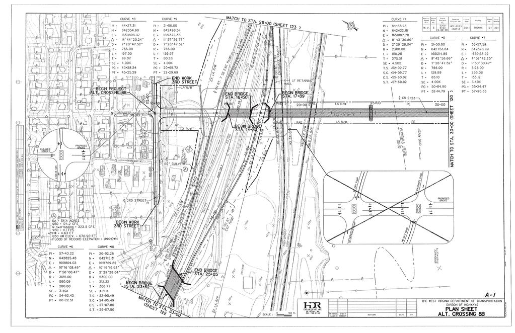
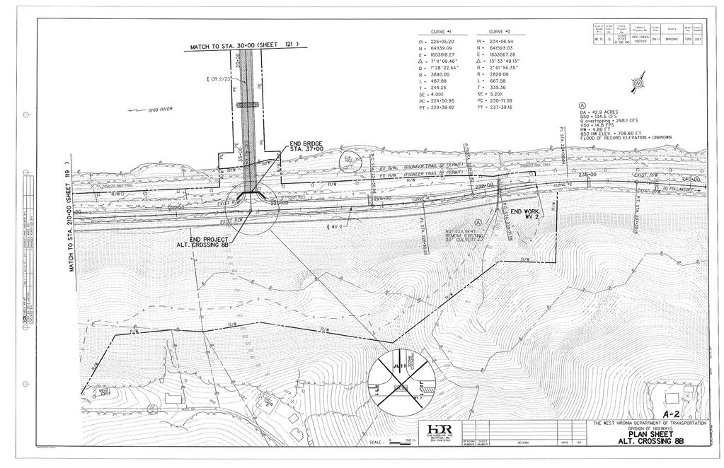
4 Proposed Ohio River Bridge Deck Width Study Report Wellsburg Bridge Over the Ohio River Project No: S205-2/ INTRODUCTION AND BACKGROUND Purpose and Scope HDR Engineering, Inc. (HDR) has conducted these studies and prepared this report with the primary objective of determining the relative cost of various deck width options for the Proposed Ohio River Bridge, generally referred to as the Wellsburg Bridge. This study is based on the Alternative Crossing 8B alignment and configuration as shown in Appendix A (Sheets A-1 through A-3). Alternative 8B is the Preferred Alternative, as described in the most recent environmental documents (see the Finding of No Significant Impact and Section 4(f) de minimis Determination dated December 2013), and Final Design Report (submitted in May, 2013) for this project. The cost estimates developed for this study encompass only the mainline bridges, where the deck width is in question. This includes County Route 2/23 from an abutment located in the vicinity of WV Route 2, across the Pioneer Trail, the Ohio River and several railroads in OH, to an abutment located between the railroads and OH Route 7. They also include the simple span bridge over OH Route 7. It should be noted that the cost of the following construction work is not included in the cost estimates as it would be relatively constant for any of the deck width options: Earthwork (including the hillside cut adjacent to WV2 which will have a relatively high cost) Other Roadway Work (Pavement, Drainage, Etc.) Approach Slabs Off Bridge ighting and Electrical Walls on Hillside Above WV2 Structural Work associated with ultimate configuration of Alternative 8B (i.e. modification or replacement of OH Route 7 Bridges and associated walls). Other non-bridge construction work not specifically listed These cost estimates have been prepared based on numerous assumptions that are discussed later in this report. Engineering judgment, historical data and preliminary criteria and design tools were utilized to establish the assumed structural configurations and member sizes included in the estimates. No detailed numerical structural analyses were performed for this study. Viable Structure Types and Span Arrangements At this early stage in the project, the type of main span structure that will be advanced through final design has not been determined. Based on previous project studies and bridges of similar length that have been constructed recently, there are several structure types that are most viable for this crossing. It should be noted that the lengths provided are approximate and will be refined during preliminary design, as appropriate and acceptable substructure locations are determined. For all alternative main river bridge alternatives, a simple span bridge over Ohio Route 7 (approximately 150 long) will also be required. The viable main structure types include: Simple Span Tied Arch - This structure would have an 845 main span over the Ohio River navigation channel with pier locations as identified in the Seamen s Church Institute simulations and as directed by the USCG. Girder approach units, consisting of multiple spans, would be required on both the WV (430 total length) and OH (618 total length) sides of the main span. 3-Span Continuous Truss - This structure would have an 845 main span over the Ohio River navigation channel with pier locations as identified in the Seamen s Church Institute simulations and as directed by the USCG. Side spans of the truss would be approximately 430 long. On the WV side, the truss side span would extend to the WV abutment, therefore no approach unit would be required. On the OH side, an approach unit of approximately 190 total length, comprised of either a simple span or multiple spans, would be required. 3-Span Continuous Cable-Stayed - This structure would have an 845 main span (minimum) over the Ohio River navigation channel with tower locations as identified in the Seamen s Church Institute simulations and as directed by the USCG. It is possible that in order to properly balance the spans for the cable-stayed bridge, the main span length may be somewhat longer than the 845 minimum. End spans of the cable-stayed bridge would be approximately 430 long. On the WV side, the end span would extend to the WV abutment, therefore no approach unit would be HDR ONE COMPANY Many Solutions May, Pennsylvania Avenue Weirton, West Virginia Page 1
5 Proposed Ohio River Bridge Deck Width Study Report Wellsburg Bridge Over the Ohio River Project No: S205-2/ required. On the OH side, an approach unit of 190 (or less if the main span is extended) total length would be required, and would be comprised of either a simple span or multiple spans. Minimum Number of anes As part of this study, in order to determine the minimum number of lanes required to meet traffic demands, HDR prepared revised traffic analyses using ODOT provided Certified Traffic data dated April 2, These data included the redevelopment site, known as the Beech Bottom Industrial Park, located south of the proposed bridge. Turn lane analyses for opening day (2017) and design year (2037) for Alternative 8B both with and without ramps were prepared. The findings are summarized below and shown graphically in Appendix A on Sheet A-4. Recommended turn lane lengths: CR 2/23 EB left-turn to WV 2 NB: 300 minimum storage plus 180 taper CR 2/23 WB right-turn to OH SR 7 NB: 300 minimum storage plus 180 taper CR 2/23 EB left-turn to OH SR 7 NB: 375 minimum storage plus 180 taper (note, this storage occurs between the proposed OH SR 7 ramps and storage/taper may not be achieved due to ramp termini locations) CR 2/23 WB right-turn to 3 rd Street NB: 220 plus 180 storage (note, this storage occurs between 3 rd Street and the proposed OH SR 7 SB ramps and storage/taper may not be achieved due to ramp termini location) Based on the analyses, a portion of the taper for the CR 2/23 EB left-turn to WV 2 NB will occur on the main span of the bridge. Also shown on Sheet A-4 are the approximate limits of both a Simple Span River Bridge unit (Tied Arch) and a 3-Span Continuous River Bridge unit (Truss or Cable-Stayed). As can be seen, a significant portion of the 3-Span Continuous River Bridge unit is within the limits of the alignment which require a minimum of three lanes. Given that varying the width of river bridges along their length can create undesirable complexities at little to no construction cost savings, the decision has been made (with concurrence from the WVDOH) that three lanes will be provided for the entire limit of any possible River Bridge units (controlled by the 3-Span Continuous River Bridge types). This will result in no specific bridge type (such as the Simple Span Tied Arch) having an economic advantage in the Span Arrangement and TS& Studies that will be performed later in the project. It should also be noted that the remaining portion of the Ohio approach to the possible River Bridge units and the bridge over Ohio Route 7 also require a minimum of three lanes. Using this approach, three lanes will be provided on all of the mainline bridges. Different shoulder widths along with possible options for pedestrian/shared use facilities will also be investigated. For each option studied, the proposed width will be held constant along the entire length of the alignment. Based on the results of the traffic studies, it appears that four lane structures should not be necessary to accommodate the traffic volumes currently projected. It should be noted, however, that some of the three lane options that will be studied could accommodate four lanes at some time in the future by utilizing the shoulders. Deck Width Options Evaluated Based on the considerations discussed in the previous section, along with input from the WVDOH, the options for the deck width listed below were considered in this study. While there are other possible combinations of number of lanes, shoulder width and pedestrian/shared use facility configuration, it is believed that the options studied include practical lower and upper bound values for the width, and will yield relative cost information that can be utilized to determine the appropriate configuration to advance to preliminary design. For these studies, it is assumed that all lanes are 12 wide, traffic barriers are T-4 and are assumed to be 1-3 wide, and pedestrian rail (outside of shared use path or sidewalk) is assumed to be 1-0 wide. Based on the proposed design speed (40 mph) and likelihood that actual speeds may exceed this limit, any proposed sidewalk or shared use path will be separated from traffic by a T-4 barrier for safety. A complete table of Roadway Design Criteria is provided in Appendix C. It is assumed that there are 3 different alternates for pedestrian accommodation, including: A. No pedestrian accommodation (no sidewalk, widened shoulder or shared-use path). B. A separated shared use path with 1 pedestrian rail on one side of the bridge, outside of the lanes, shoulders and traffic barriers. This shared use path is to be a minimum of 8 wide HDR ONE COMPANY Many Solutions May, Pennsylvania Avenue Weirton, West Virginia Page 2
6 Proposed Ohio River Bridge Deck Width Study Report Wellsburg Bridge Over the Ohio River Project No: S205-2/ and preferred 10 wide. For this study an 8 wide path has been assumed to determine the overall required deck width. C. A 5 wide separated sidewalk with 1 pedestrian rail on one side of the bridge outside of the lanes, shoulders and traffic barriers. Bicycle traffic will use shoulders. Option 1 3 lanes with 2 shoulders: o Option 1A No Pedestrian Facilities Out-to-Out of Deck o Option 1B Shared-Use Path 51-6 Out-to-Out of Deck o Option 1C Sidewalk and One 8 Shoulder 54-6 Out-to-Out of Deck Option 2 3 lanes with 4 shoulders: o Option 2A No Pedestrian Facilities Out-to-Out of Deck o Option 2B Shared-Use Path 55-6 Out-to-Out of Deck o Option 2C Sidewalk and One 8 Shoulder 56-6 Out-to-Out of Deck Option 3 3 lanes with 6 shoulders: o Option 3A No Pedestrian Facilities Out-to-Out of Deck o Option 3B Shared-Use Path 59-6 Out-to-Out of Deck o Option 3C Sidewalk 56-6 Out-to-Out of Deck Option 4 3 lanes with 8 shoulders: o Option 4A No Pedestrian Facilities Out-to-Out of Deck o Option 4B Shared-Use Path 63-6 Out-to-Out of Deck o Option 4C Sidewalk 60-6 Out-to-Out of Deck It should be noted that the options listed below could either initially or at some time in the future accommodate an additional (fourth) lane without structural modifications, by striping as follows. These options would maintain a minimum of 11 wide lanes and 2 wide shoulders: Option 2C, 3A, 3B and 3C Four 11 anes with 2 Shoulders Option 4A, 4B and 4C Four 11 anes with 4 Shoulders or Four 12 anes with 2 Shoulders However, such use would be at the discretion of the Department and might necessitate the need for a design exception. Typical Sections for each of the twelve options are provided in Appendix A on Sheets A-7 through A-14 for the Approach Units and on Sheets A-15 through A-22 for the Main River Bridge. As indicated by the WVDOH, the ability to maintain a minimum of two lanes of traffic on the bridges during future redecking operations would be important. If it is assumed that for the temporary condition, 11' lanes and no shoulders would be permitted, options with a curb-to-curb width of at least 48-0 could be redecked while maintaining 2 lanes of traffic (assuming the use of mechanical couplers and temporary concrete barrier less than 2 wide). It should be noted that additional work could be required during the redecking, such as providing a temporary stringer under the partially demolished/partially constructed deck overhangs. The options which meet this criteria are Options 2C, 3A, 3B, 3C, 4A, 4B, and 4C. The ability to maintain a minimum of two lanes of traffic on the bridges during future redecking will avoid lengthy traffic detours and delays. This may result in cost savings from eliminating the need for maintenance and protection of traffic along detour routes and road user cost associated with traffic delays. Additional savings may also be realized by eliminating the need for accelerated construction that may be desired with options that do not allow for two lane traffic during redecking. Maintaining traffic during bridge inspection is also a consideration. A bridge inspection crane requires a minimum lane width of 12. A telescopic boom lift (manlift) with the capacity to reach the highest points of the bridge superstructure above the bridge deck requires an approximate lane width of 15. Options with a curb-to-curb width of at least 48-0 could accommodate three 11 lanes (with no shoulders) and bridge inspection vehicles.. HDR ONE COMPANY Many Solutions May, Pennsylvania Avenue Weirton, West Virginia Page 3
7 Proposed Ohio River Bridge Deck Width Study Report Wellsburg Bridge Over the Ohio River Project No: S205-2/ ASSUMPTIONS AND DESCRIPTION OF BRIDGES Structure Type Estimated and Distribution of Cost Based On ine ocation For this study, the Simple Span Tied Arch was selected as the main river bridge structure type for which cost estimates have been generated. The tied arch was selected for a number of reasons. First, this type is the most straightforward type to estimate, with a fairly well-defined configuration (less variability in design choices that could be assumed). Also, there is a relatively large amount of historical data and rules of thumb available to develop preliminary sizes for primary structural members. Finally, for purposes of capturing the split of bridge cost between WV and OH, this simple span bridge type is less complicated. It is believed, however, that the results obtained for the tied arch, specifically the relative cost of the various deck widths studied, are representative of those that would be obtained for the other structure types. As requested by the WVDOH and ODOT, the estimated costs determined for each deck width option have been allocated to the two agencies based on the location of the ine, as identified on the current USGS mapping. This location is shown in Appendix A on Sheet A-5 and occurs at approximately Station on the Alternative 8B alignment. With the ine located at this station, approximately 75% of the simple span tied arch is located within West Virginia and 25% within Ohio. Therefore, for the cost estimates, the following split has been used: WV Cost: WV Approach Spans 75% of Simple Span Tied Arch OH Cost: OH Approach Spans OH Route 7 Overpass Bridge 25% of Simple Span Tied Arch For all of the deck width options investigated, the percentage of the overall mainline bridge cost remained relatively constant as shown below: % of Total Mainline Bridge Cost: WV 65% OH 35% The estimated cost for each option supporting these percentages is provided in the section, Estimated Construction Cost, which can be found later in this report. While OH has only been assigned 25% of the main span cost, the fact that the OH approach is longer (and includes the OH Route 7 Overpass Bridge) results in the OH percentage of the total mainline bridge cost being greater than 25%. It should be noted that based on the cost estimates prepared for the Final Design Report, besides the mainline bridge cost, the largest elements of work on the project include the hillside excavation and wall along WV Route 2 (fully within WV and estimated at ~$21 million), and the other bridge and wall work required in OH for the ultimate 8B configuration (fully within OH and estimated at ~$19 million). Main Unit Description The simple span tied arch river bridge is assumed to 845 long which, when the width of river piers and slight skew of the navigation channel are taken into account, will provide the required 800 clear navigation clearance. The span is assumed to have vertical arches, although inclined arches in a basket-handle configuration is also viable. A diamond-shaped top lateral bracing system and a K-type bottom lateral bracing system is utilized. The tied arch has a networked system of hangers between the arch rib and tie girder, as this type of system has been shown to be more efficient than vertical hangers. For this study, it is assumed that the hangers intersect the tie girder at increments of 32-6, and a floorbeam is present at each intersection point. A conventional reinforced concrete deck is supported by steel rolled beam stringers which are supported on top of the floorbeams. Preliminary details of the Main River Bridge superstructure are provided in Appendix A on Sheets A-23 through A-25. HDR ONE COMPANY Many Solutions May, Pennsylvania Avenue Weirton, West Virginia Page 4
8 Proposed Ohio River Bridge Deck Width Study Report Wellsburg Bridge Over the Ohio River Project No: S205-2/ The two main river piers (Piers 3 and 4) are shown in Appendix A on Sheet A-30 and are assumed to have two large circular columns that begin 3 feet above the 100 year flood elevation of the river and which support one arch each. Below the circular columns, a single large solid shaft is utilized to resist potential barge impact forces. The solid shaft extends down to a footing on top of a tremie seal founded on bedrock. Dimensions for the substructure elements were selected based on geometry and past experience. Approximate elevations for the top of rock and mudline have been assumed for this study. It has also been assumed that the cofferdams in the river that would facilitate construction would extend from the top of rock to an elevation 3 feet above the normal pool elevation. West Virginia Approach Description For the 430 long WV Approach Unit, a two-span ( ) steel plate girder structure has been assumed. For each of the twelve deck width options, a reasonable girder spacing has been utilized. The girder spacing was selected to meet the requirements of the WVDOH for use of the standard 8 Class H deck with reinforcement based on the empirical design methodology with standard overhang reinforcement. The pier supporting this unit (Pier 5) is shown in Appendix A on Sheet A-29. The upper portion of this pier is assumed to be of a hammerhead configuration. However, since this pier is still within the flood plain, it is assumed that a larger solid shaft section will be required below a point three feet above the 100 year flood elevation to resist potential barge impact forces. The solid shaft extends down to a footing on top of a tremie seal founded on bedrock. Dimensions for the substructure elements were selected based on geometry and past experience. Approximate elevations for the top of rock and mudline have been assumed for this study. It has also been assumed that the cofferdams in the river that would facilitate construction would extend from the top of rock to an elevation 3 feet above the normal pool elevation. The WV Abutment is assumed to be a full-height abutment with flared wingwalls founded on steel H-piles as shown in Appendix A on Sheets A-26 and A-27. Ohio Approach Description For the 618 long OH Approach Unit, a three-span ( ) steel plate girder structure has been assumed. For each of the twelve deck width options, a girder spacing similar to that used on the WV approach for the same deck width option has been utilized. Since ODOT does not utilize the empirical deck design method, the deck thickness for the different options varies and is based on the ODOT Bridge Manual Section There are two piers supporting this unit. Pier 2 is shown in Appendix A on Sheet A-29. The upper portion of this pier is assumed to be of a hammerhead configuration. However, since this pier is still within the flood plain, it is assumed that a larger solid shaft section will be required below a point three feet above the 100 year flood elevation to resist potential barge impact forces. The solid shaft extends down to a footing on top of a tremie seal founded on bedrock. Dimensions for the substructure elements were selected based on geometry and past experience. Approximate elevations for the top of rock and mudline have been assumed for this study. It has also been assumed that the cofferdams in the river that would facilitate construction would extend from the top of rock to an elevation 3 feet above the normal pool elevation. The other pier (Pier 1) is outside of the floodplain and is assumed to be a hammerhead type pier with the footing founded on steel H-piles, as shown in Appendix A on Sheet A-28. The OH Abutment is assumed to be a full-height abutment with flared wingwalls founded on steel H-piles as shown in Appendix A on Sheets A-26 and A-27. Ohio Route 7 Overpass Bridge Description For the 150 long simple span OH Route 7 Overpass Bridge, a steel plate girder structure has been assumed. For each of the twelve deck width options, a girder spacing similar to that used on the WV and OH approaches for the same deck width option has been utilized. Since ODOT does not utilize the empirical deck design method, the deck thickness for the different options varies and is based on the ODOT Bridge Manual Section There are no piers for this unit. Both abutments are assumed to be full-height with flared wingwalls founded on steel H-piles as shown in Appendix A on Sheets A-26 and A-27. HDR ONE COMPANY Many Solutions May, Pennsylvania Avenue Weirton, West Virginia Page 5
9 Proposed Ohio River Bridge Deck Width Study Report Wellsburg Bridge Over the Ohio River Project No: S205-2/ MISCEOUS STRUCTURES INFORMATION Superstructure Joints It is anticipated that expansion joints of the type and movement capacity indicated will be provided at the following locations. To size the joints, an assumed thermal variation of 150 degrees per the WV Bridge Design Manual was assumed. Bearing fixities assumed to compute the associated expansion lengths are identified in Appendix A on Sheet A-6: OH Route 7 Both Abutments Integral with 3 Strip Seal at ends of approach slabs OH Approach Abutment - Semi-Integral with 6 Modular Dam at end of approach slab Pier 3 Juncture of OH plate-girder approach and tied arch 3 Strip Seal Pier 4 - Juncture of WV plate-girder approach and tied arch 13 Modular Dam WV Approach Abutment Semi-Integral with 3 Strip Seal at end of approach slab Bridge Materials Structural Steel - All steel plate-girder approach units to utilize AASHTO M270 Gr. 50W. The tied arch is to utilize a combination of AASHTO M270 Gr. 50W (approximately 75% of the total) and Gr. HPS 70W steel (approximately 25% of the total utilized in highly stressed regions). It is anticipated that unpainted weathering steel will be used for all approach units and for the majority of the floor system of the tied arch. It is assumed that the arch floorsystem near the limits of the deck along with any structural steel above the level of the deck will be painted. Reinforced Concrete - It has been assumed that normal strength reinforced concrete will be used, as follows: Deck and Barriers - f c = 4000 psi Piers and Abutments - f c = 3000 psi Tremie f c = 2000 psi Bearings It is anticipated that laminated elastomeric pads will be used for all of the bearings for the WV and OH approach units. It is anticipated that large capacity disc-type bearings will be used for all four bearings for the tied arch. Deck Drainage It is anticipated that scuppers and downspouts will be required for all of the options. While the narrow deck options may have a somewhat lower demand, for all of the options a constant lump sum amount ($150,000) has been included in each option. Roadway and Navigation ighting and Electrical It is anticipated that roadway lightling, a navigation lighting system and electrical work will be required for all of the options. A constant lump sum amount ($250,000) has been included in each option for these items. HDR ONE COMPANY Many Solutions May, Pennsylvania Avenue Weirton, West Virginia Page 6
10 Proposed Ohio River Bridge Deck Width Study Report Wellsburg Bridge Over the Ohio River Project No: S205-2/ ESTIMATED CONSTRUCTION COSTS For each deck width option, a detailed estimate of quantities and corresponding cost estimate for the mainline bridges has been prepared. The supporting calculations including the breakdown of items, quantities and unit costs are not included in this report, but are available if requested. For these cost estimates, unit costs based on recent bid data and historical data adjusted for inflation have been utilized. A summary of the total mainline bridge costs is provided in the table to the right. For more in-depth information, such as WV and OH calculated shares, cost per square foot of bridge deck and breakdown of substructure/superstructure cost, see Appendix B, Sheets B-1 through B-4. Note that a 10% contingency has been included in each. As previously described, for all of the deck width options investigated, the percentage of the overall mainline bridge cost remained relatively constant as shown below: % of Total Mainline Bridge Cost: WV 65% OH 35% Also indicated in the table are the options which provide pedestrian accommodation (sidewalk or shared use), bicycle accommodation (shared use or shoulder), options which will not need a design exception, options which could be restriped for 4 lanes of traffic as previously discussed, and options which could be re-decked while maintaining 2 lanes of traffic. Option 2C and 3C are the narrowest and lowest cost options that meet all of the desirable criteria listed in the table. Therefore, they have been used as the baseline for the Normalized Cost column in the table. Option Tabulation of Estimated Mainline Bridge Cost * Option Description Out-to-Out Deck Total Bridge Cost Pedestrian Accommodation Bicycle Accommodation No Design Exception Required 4 Future anes Possible Redeckable Maintaining 2 anes 1A 3 anes; 2 Shoulders; No Ped. Facilities 42-6 $ B 3 anes; 2 Shoulders; Shared-Use 51-6 $65.2 X X C 3 anes; 2 & 8 Shoulders; Sidewalk 54-6 $67.4 X X A 3 anes; 4 Shoulders; No Ped. Facilities 46-6 $60.9 X B 3 anes; 4 Shoulders; Shared-Use 55-6 $68.1 X X X C 3 anes; 4 & 8 Shoulders; Sidewalk 56-6 $69.7 X X X X X A 3 anes; 6 Shoulders; No Ped. Facilities 50-6 $64.1 X X X X B 3 anes; 6 Shoulders; Shared-Use 59-6 $71.4 X X X X X C 3 anes; 6 Shoulders; Sidewalk 56-6 $69.7 X X X X X A 3 anes; 8 Shoulders; No Ped. Facilities 54-6 $67.9 X X X X B 3 anes; 8 Shoulders; Shared-Use 63-6 $75.1 X X X X X C 3 anes; 8 Shoulders; Sidewalk 60-6 $73.1 X X X X X 1.05 Normalized Cost * Cost in Millions for Main Span, WV Approach, OH Approach and OH 7 Overpass Bridge HDR ONE COMPANY Many Solutions May, Pennsylvania Avenue Weirton, West Virginia Page 7
11 Proposed Ohio River Bridge Deck Width Study Report Wellsburg Bridge Over the Ohio River Project No: S205-2/ CONCUSIONS Based on the cost estimates developed, it appears that the relationship between deck width and to the 5 wide separated sidewalk because it provides a safer condition for bicycles which can use the path as opposed to the shoulder. In addition, should Option 2C or 3C ever be striped for 4 lanes, there would be no bicycle accommodation possible. anticipated mainline bridge cost is linear in this range of deck widths. The chart on this page is a plot of the deck width and cost for the 12 options studied along with a linear trendline. This chart Mainline Bridge Cost can be used to estimate the cost of deck widths not included in this study. It should be noted that $100 the slope of the trendline is not such that a percentage increase in overall deck width results in the same percentage increase in cost. For example, Option 4B is approximately 50% wider than $90 Option 1A, but the cost is only 29% higher. This is due to the fact that there are fixed costs associated with all of the options. Two such items include: The same size river pier solid shaft section will be required to resist potential barge impact forces regardless of the deck width. For any deck width, the arch hanger configuration and total length remains the same. While the diameter of the hangers may change somewhat, this is a material savings which is Cost in Millions of Dollars $80 $70 $60 Cost inear (Cost) relatively small on an item where the majority of the cost is associated with the end $50 connections, fabrication and installation. No recommendations are being made as part of this study report on which option should be advanced to preliminary design, as such decisions are dependent on available funding. However, the following generalizations can be made: $ Deck Width in Feet (Out-to-Out) For a given lane/shoulder configuration, adding the 8 shared-use path increases the cost by approximately $6.8 to $7.3 million. For a given lane/shoulder configuration, adding a 5 sidewalk and increasing one of the shoulders to 8 increases the cost from $9 million for Option 1 down to $5.2 million for Option 4. There are 5 options which meet all of the desirable criteria shown in the table on Page 7 Options 2C, 3B, 3C, 4B and 4C. Of these five options, Option 3B is considered the preferred option. It is only slightly (2%) higher in cost than the two lowest of the five (Option 2C and 3C). However, it provides an 8 wide separated shared use path which is preferable HDR ONE COMPANY Many Solutions May, Pennsylvania Avenue Weirton, West Virginia Page 8
12 Proposed Ohio River Bridge Deck Width Study Report Wellsburg Bridge Over the Ohio River Project No: S205-2/ STRUCTURA PAN DESCRIPTION The structural plans for the options are included in Appendix A. The following list describes the material covered on each plan sheet: Sheets Description A-1 to A-3 Roadway Plan and Profile for Alternative 8B A-4 Minimum Number of anes A-5 Assumed Funding Split A-6 Assumed Fixities, Joints and Bearings A-7 to A-14 Approach Typical Sections A-15 to A-22 Main River Bridge Typical Sections A-23 to A-25 Main River Bridge Superstructure A-26 to A-27 Abutments and Wingwalls A-28 to A-30 Piers HDR ONE COMPANY Many Solutions May, Pennsylvania Avenue Weirton, West Virginia Page 9
13 Proposed Ohio River Bridge Deck Width Study Report Wellsburg Bridge Over the Ohio River Project No: S205-2/ APPENDIX A - DRAWINGS HDR ONE COMPANY Many Solutions May, Pennsylvania Avenue Weirton, West Virginia Page A-0
14
15

16
17 IMIT OF 3-SPAN CONTINUOUS RIVER BRIDGE IMIT OF SIMPE SPAN RIVER BRIDGE 220 OH 7 EXIT RAMP 375 OH 7 ENTRANCE RAMP 300 OH 7 ENTRANCE RAMP OH 7 EXIT RAMP 3 S MIN. FOR RT TURNS TO 3 RD ST. NB 3 S MIN. FOR RT AND T TURNS TO OH 7 NORTHBOUND ENTRANCE RAMP 180 TAPER 2 S MIN. 180 TAPER S MIN. THIRD FOR EFT TURN TO WV2 NORTH /- MINIMUM OF S A-4
18 STATE INE BASED ON USGS MAPPING APPROX. STA ( 25% ) 635 ( 75% ) OH WV ASSUMED FUNDING SPIT A-5
19 ~ 80 STRIP SEA 3 MOVT. CAP. AT END OF APPR. SAB MODUAR JOINT 6 MOVT. CAP. AT END OF APPR. SAB STRIP SEA 3 MOVT. CAP. MODUAR JOINT 13 MOVT. CAP. STRIP SEA 3 MOVT. CAP. AT END OF APPR. SAB I I E, SI E F E F E E F E, SI NOTE: A BEARINGS TO BE REINFORCED EASTOMERIC EXCEPT ARCH BEARINGS TO BE DISC TYPE. NOTE: ASSUMED T = 150 PER WVBDM (-30 TO 120 ) ASSUMED FIXITIES, JOINTS & BEARINGS A-6
20 J04C22C03 - BRIDGE b Public Roads Div. Dist. Project Federal Project Fiscal Year County Sheet Total Sheets W.V. S205-2/ HPP (003)D BROOKE 42'-6" OUT-TO-OUT '-0" CURB-TO-CURB B SHD. SHD. CONCRETE DECK SEE NOTE 1 T-4 BARRIER WV APPROACH - 8" CASS H OH APPROACH - 9 " CASS QC2 3'-7 " 3 GIRDER SPACES AT 11'-9" = 35'-3" 3'-7 " OPTION 1A - 3 S; 2' SHOUDERS 4' 2' 0 4' SCAE: " = 1'-0" 51'-6" OUT-TO-OUT NOTES: 30'-3" 2 40'-0" CURB-TO-CURB B 1. T-4 BARRIER MAY BE BARRIER AONE OR COMBINATION OF BARRIER AND RAIING (AS SHOWN). IN EITHER CASE, TOTA HEIGHT OF T-4 BARRIER SHA BE A MINIMUM OF 48". 1'-0" SHARED USE PATH SHD. SHD. 2. PEDESTRIAN RAI HEIGHT SHA BE A MINIMUM OF 48". SEE NOTE 2 PEDESTRIAN RAI 8'-0" MINIMUM 10'-0" PREFERRED (SEE NOTE 3) SEE NOTE 1 CONCRETE DECK WV APPROACH - 8" CASS H OH APPROACH - 9 " CASS QC2 T-4 BARRIER 3. OTHER SECTION DIMENSIONS BASED ON 8'-0" SHARED USE PATH WIDTH. 4 GIRDER SPACES AT 1 = 45'-0" OPTION 1B - 3 S; 2' SHOUDERS; SHARED-USE PATH 4' 2' 0 4' SCAE: " = 1'-0" DESIGNED DRAWN APPROACHES BY THE WEST VIRGINIA DEPARTMENT OF TRANSPORTATION DIVISION OF HIGHWAYS WESBURG BRIDGE TYPICA SECTION OPTIONS HDR ENGINEERING, INC. OF CONSUTING ENGINEERS BRIDGE NO. WEIRTON, W.VA A-7 $$$$$$$$$FIENAME$$$$$$$$ $USERNAME$ DD-MMM-YYYY HH:MM
21 J04C22C03 - BRIDGE b Public Roads Div. Dist. Project Federal Project Fiscal Year County Sheet Total Sheets W.V. S205-2/ HPP (003)D BROOKE 54'-6" OUT-TO-OUT '-0" CURB-TO-CURB B SHD. 1'-0" 5'-0" 8'-0" SHD. SIDEWAK SEE NOTE 2 PEDESTRIAN RAI SEE NOTE 1 CONCRETE DECK WV APPROACH - 8" CASS H OH APPROACH - 9 " CASS QC2 T-4 BARRIER 3'-9" 4 GIRDER SPACES AT 11'-9 " = 47'-0" 3'-9" OPTION 1C - 3 S; 2' & 8' SHOUDERS; SIDEWAK 4' 2' 0 4' SCAE: " = 1'-0" NOTES: 1. T-4 BARRIER MAY BE BARRIER AONE OR COMBINATION OF BARRIER AND RAIING (AS SHOWN). IN EITHER CASE, TOTA HEIGHT OF T-4 BARRIER SHA BE A MINIMUM OF 48". 2. PEDESTRIAN RAI HEIGHT SHA BE A MINIMUM OF 48". DESIGNED DRAWN APPROACHES DIVISION OF HIGHWAYS THE WEST VIRGINIA DEPARTMENT OF TRANSPORTATION WESBURG BRIDGE TYPICA SECTION OPTIONS HDR ENGINEERING, INC. CONSUTING ENGINEERS WEIRTON, W.VA A-8 OF BRIDGE NO. BY $$$$$$$$$FIENAME$$$$$$$$ $USERNAME$ DD-MMM-YYYY HH:MM
22 J04C22C03 - BRIDGE b Public Roads Div. Dist. Project Federal Project Fiscal Year County Sheet Total Sheets W.V. 6 S205-2/ HPP (003)D 2013 BROOKE 46'-6" OUT-TO-OUT '-0" CURB-TO-CURB B 4'-0" 4'-0" SHD SHD SEE NOTE 1 CONCRETE DECK WV APPROACH - 8" CASS H OH APPROACH - 9" CASS QC2 T-4 BARRIER 4 GIRDER SPACES AT 10'-0" = 40'-0" OPTION 2A - 3 S; 4' SHOUDERS 4' 2' 0 4' SCAE: " = 1'-0" 55'-6" OUT-TO-OUT 32'-3" 2 NOTES: SEE NOTE 2 RAI 1'-0" PEDESTRIAN SHARED USE PATH 8'-0" MINIMUM 10'-0" PREFERRED (SEE NOTE 3) 4'-0" SHD SEE NOTE 1 44'-0" CURB-TO-CURB B CONCRETE DECK WV APPROACH - 8" CASS H OH APPROACH - 8ƒ" CASS QC2 4'-0" SHD T-4 BARRIER T-4 BARRIER MAY BE BARRIER AONE OR COMBINATION OF BARRIER AND RAIING (AS SHOWN). IN EITHER CASE, TOTA HEIGHT OF T-4 BARRIER SHA BE A MINIMUM OF 48". PEDESTRIAN RAI HEIGHT SHA BE A MINIMUM OF 48". OTHER SECTION DIMENSIONS BASED ON 8'-0" SHARED USE PATH WIDTH. 3'-4 " 5 GIRDER SPACES AT 9'-9" = 48'-9" 4' 2' 0 4' SCAE: " = 1'-0" 3'-4 " OPTION 2B - 3 S; 4' SHOUDERS; SHARED-USE PATH DESIGNED DRAWN APPROACHES DIVISION OF HIGHWAYS THE WEST VIRGINIA DEPARTMENT OF TRANSPORTATION WESBURG BRIDGE TYPICA SECTION OPTIONS HDR ENGINEERING, INC. CONSUTING ENGINEERS WEIRTON, W.VA OF BRIDGE NO. A-9 BY $$$$$$$$$FIENAME$$$$$$$$ $USERNAME$ DD-MMM-YYYY HH:MM
23 J04C22C03 - BRIDGE b Public Roads Div. Dist. Project Federal Project Fiscal Year County Sheet Total Sheets W.V. 6 S205-2/ HPP (003)D 2013 BROOKE 56'-6" OUT-TO-OUT '-0" CURB-TO-CURB B 1'-0" 5'-0" 8'-0" 4'-0" SIDEWAK SHD. SHD SEE NOTE 2 RAI PEDESTRIAN SEE NOTE 1 CONCRETE DECK WV APPROACH - 8" CASS H OH APPROACH - 9" CASS QC2 T-4 BARRIER 5 GIRDER SPACES AT 10'-0" = 50'-0" OPTION 2C - 3 S; 4' & 8' SHOUDERS; SIDEWAK 4' 2' 0 4' SCAE: " = 1'-0" NOTES: 1. T-4 BARRIER MAY BE BARRIER AONE OR COMBINATION OF BARRIER AND RAIING (AS SHOWN). IN EITHER CASE, TOTA HEIGHT OF T-4 BARRIER SHA BE A MINIMUM OF 48". 2. PEDESTRIAN RAI HEIGHT SHA BE A MINIMUM OF 48". DESIGNED DRAWN APPROACHES DIVISION OF HIGHWAYS THE WEST VIRGINIA DEPARTMENT OF TRANSPORTATION WESBURG BRIDGE TYPICA SECTION OPTIONS HDR ENGINEERING, INC. CONSUTING ENGINEERS WEIRTON, W.VA OF BRIDGE NO. A-10 BY $$$$$$$$$FIENAME$$$$$$$$ $USERNAME$ DD-MMM-YYYY HH:MM
24 J04C22C03 - BRIDGE b Public Roads Div. Dist. Project Federal Project Fiscal Year County Sheet Total Sheets W.V. 6 S205-2/ HPP (003)D 2013 BROOKE 50'-6" OUT-TO-OUT 25'-3" 25'-3" 48'-0" CURB-TO-CURB B 6'-0" 6'-0" SHOUDER SHOUDER SEE NOTE 1 CONCRETE DECK WV APPROACH - 8" CASS H OH APPROACH - 9 " CASS QC2 T-4 BARRIER 4 GIRDER SPACES AT 11'-0" = 44'-0" OPTION 3A - 3 S; 6' SHOUDERS 4' 2' 0 4' SCAE: " = 1'-0" 59'-6" OUT-TO-OUT 34'-3" 25'-3" SEE NOTE 2 1'-0" PEDESTRIAN RAI SHARED USE PATH 8'-0" MINIMUM 10'-0" PREFERRED (SEE NOTE 3) 6'-0" SHOUDER SEE NOTE 1 48'-0" CURB-TO-CURB B CONCRETE DECK WV APPROACH - 8" CASS H 6'-0" SHOUDER OH APPROACH - 9 " CASS QC2 T-4 BARRIER NOTES: T-4 BARRIER MAY BE BARRIER AONE OR COMBINATION OF BARRIER AND RAIING (AS SHOWN). IN EITHER CASE, TOTA HEIGHT OF T-4 BARRIER SHA BE A MINIMUM OF 48". PEDESTRIAN RAI HEIGHT SHA BE A MINIMUM OF 48". OTHER SECTION DIMENSIONS BASED ON 8'-0" SHARED USE PATH WIDTH. 3'-6" 5 GIRDER SPACES AT 10'-6" = 52'-6" 3'-6" OPTION 3B - 3 S; 6' SHOUDERS; SHARED-USE PATH 4' 2' 0 4' SCAE: " = 1'-0" DESIGNED DRAWN APPROACHES DIVISION OF HIGHWAYS THE WEST VIRGINIA DEPARTMENT OF TRANSPORTATION WESBURG BRIDGE TYPICA SECTION OPTIONS HDR ENGINEERING, INC. CONSUTING ENGINEERS WEIRTON, W.VA OF BRIDGE NO. A-11 BY $$$$$$$$$FIENAME$$$$$$$$ $USERNAME$ DD-MMM-YYYY HH:MM
25 J04C22C03 - BRIDGE b Public Roads Div. Dist. Project Federal Project Fiscal Year County Sheet Total Sheets W.V. 6 S205-2/ HPP (003)D 2013 BROOKE 56'-6" OUT-TO-OUT 3 25'-3" 48'-0" CURB-TO-CURB B 1'-0" 5'-0" 6'-0" 6'-0" SIDEWAK SHOUDER SHOUDER SEE NOTE 2 PEDESTRIAN RAI SEE NOTE 1 CONCRETE DECK WV APPROACH - 8" CASS H OH APPROACH - 9" CASS QC2 T-4 BARRIER 5 GIRDER SPACES AT 10'-0" = 50'-0" OPTION 3C - 3 S; 6' SHOUDERS; SIDEWAK 4' 2' 0 4' SCAE: " = 1'-0" NOTES: 1. T-4 BARRIER MAY BE BARRIER AONE OR COMBINATION OF BARRIER AND RAIING (AS SHOWN). IN EITHER CASE, TOTA HEIGHT OF T-4 BARRIER SHA BE A MINIMUM OF 48". 2. PEDESTRIAN RAI HEIGHT SHA BE A MINIMUM OF 48". DESIGNED DRAWN APPROACHES DIVISION OF HIGHWAYS THE WEST VIRGINIA DEPARTMENT OF TRANSPORTATION WESBURG BRIDGE TYPICA SECTION OPTIONS HDR ENGINEERING, INC. CONSUTING ENGINEERS WEIRTON, W.VA A-12 OF BRIDGE NO. BY $$$$$$$$$FIENAME$$$$$$$$ $USERNAME$ DD-MMM-YYYY HH:MM
26 J04C22C03 - BRIDGE b Public Roads Div. Dist. Project Federal Project Fiscal Year County Sheet Total Sheets W.V. 6 S205-2/ HPP (003)D 2013 BROOKE 54'-6" OUT-TO-OUT 27'-3" 27'-3" 5 CURB-TO-CURB B 8'-0" 8'-0" SHOUDER SHOUDER SEE NOTE 1 CONCRETE DECK WV APPROACH - 8" CASS H OH APPROACH - 9 " CASS QC2 T-4 BARRIER 3'-9" 3'-9" 4 GIRDER SPACES AT 11'-9" = 47'-0" OPTION 4A - 3 S; 8' SHOUDERS 4' 2' 0 4' SCAE: " = 1'-0" 63'-6" OUT-TO-OUT 36'-3" 27'-3" 5 CURB-TO-CURB NOTES: 1'-0" PEDESTRIAN RAI SHARED USE PATH 8'-0" MINIMUM 10'-0" PREFERRED (SEE NOTE 3) 8'-0" SHOUDER SEE NOTE 1 SEE NOTE 2 B CONCRETE DECK WV APPROACH - 8" CASS H 8'-0" SHOUDER OH APPROACH - 9 " CASS QC2 T-4 BARRIER T-4 BARRIER MAY BE BARRIER AONE OR COMBINATION OF BARRIER AND RAIING (AS SHOWN). IN EITHER CASE, TOTA HEIGHT OF T-4 BARRIER SHA BE A MINIMUM OF 48". PEDESTRIAN RAI HEIGHT SHA BE A MINIMUM OF 48". OTHER SECTION DIMENSIONS BASED ON 8'-0" SHARED USE PATH WIDTH. 3'-7 " 5 GIRDER SPACES AT 1 = 56'-3" 3'-7 " OPTION 4B - 3 S; 8' SHOUDERS; SHARED-USE PATH 4' 2' 0 4' SCAE: " = 1'-0" DESIGNED DRAWN APPROACHES DIVISION OF HIGHWAYS THE WEST VIRGINIA DEPARTMENT OF TRANSPORTATION WESBURG BRIDGE TYPICA SECTION OPTIONS HDR ENGINEERING, INC. CONSUTING ENGINEERS WEIRTON, W.VA A-13 OF BRIDGE NO. BY $$$$$$$$$FIENAME$$$$$$$$ $USERNAME$ DD-MMM-YYYY HH:MM
27 J04C22C03 - BRIDGE b Public Roads Div. Dist. Project Federal Project Fiscal Year County Sheet Total Sheets W.V. 6 S205-2/ HPP (003)D 2013 BROOKE 60'-6" OUT-TO-OUT 3 27'-3" 5 CURB-TO-CURB B 1'-0" 5'-0" 8'-0" 8'-0" SIDEWAK SHOUDER SHOUDER SEE NOTE 2 PEDESTRIAN RAI SEE NOTE 1 CONCRETE DECK WV APPROACH - 8" CASS H OH APPROACH - 9 " CASS QC2 T-4 BARRIER 3'-4 " 5 GIRDER SPACES AT 10'-9" = 53'-9" 3'-4 " OPTION 4C - 3 S; 8' SHOUDERS; SIDEWAK 4' 2' 0 4' SCAE: " = 1'-0" NOTES: 1. T-4 BARRIER MAY BE BARRIER AONE OR COMBINATION OF BARRIER AND RAIING (AS SHOWN). IN EITHER CASE, TOTA HEIGHT OF T-4 BARRIER SHA BE A MINIMUM OF 48". 2. PEDESTRIAN RAI HEIGHT SHA BE A MINIMUM OF 48". DESIGNED DRAWN APPROACHES DIVISION OF HIGHWAYS THE WEST VIRGINIA DEPARTMENT OF TRANSPORTATION WESBURG BRIDGE TYPICA SECTION OPTIONS HDR ENGINEERING, INC. CONSUTING ENGINEERS WEIRTON, W.VA A-14 OF BRIDGE NO. BY $$$$$$$$$FIENAME$$$$$$$$ $USERNAME$ DD-MMM-YYYY HH:MM
28 J04C22C03 - BRIDGE b Public Roads Div. Dist. Project Federal Project Fiscal Year County Sheet Total Sheets W.V. 6 S205-2/ HPP (003)D 2013 BROOKE 49'-0" C. TO C. ARCHES 42'-6" OUT-TO-OUT C ARCH '-0" CURB-TO-CURB C ARCH B SHD. SHD. SEE NOTE 1 CONCRETE DECK 8" CASS H T-4 BARRIER 5 STRINGER SPACES AT 7'-8 "(+) = 38'-6" OPTION 1A - 3 S; 2' SHOUDERS 4' 2' 0 4' SCAE: " = 1'-0" 58'-0" C. TO C. ARCHES 51'-6" OUT-TO-OUT C ARCH 30'-3" 2 40'-0" CURB-TO-CURB C ARCH NOTES: SEE NOTE 2 1'-0" PEDESTRIAN RAI SHARED USE PATH 8'-0" MINIMUM 10'-0" PREFERRED (SEE NOTE 3) B SHD. SHD. SEE NOTE 1 CONCRETE DECK 8" CASS H T-4 BARRIER T-4 BARRIER MAY BE BARRIER AONE OR COMBINATION OF BARRIER AND RAIING (AS SHOWN). IN EITHER CASE, TOTA HEIGHT OF T-4 BARRIER SHA BE A MINIMUM OF 48". PEDESTRIAN RAI HEIGHT SHA BE A MINIMUM OF 48". OTHER SECTION DIMENSIONS BASED ON 8'-0" SHARED USE PATH WIDTH. 6 STRINGER SPACES AT 7'-11" = 47'-6" OPTION 1B - 3 S; 2' SHOUDERS; SHARED-USE PATH 4' 2' 0 4' SCAE: " = 1'-0" DESIGNED DRAWN MAIN RIVER BRIDGE BY THE WEST VIRGINIA DEPARTMENT OF TRANSPORTATION DIVISION OF HIGHWAYS WESBURG BRIDGE TYPICA SECTION OPTIONS HDR ENGINEERING, INC. OF CONSUTING ENGINEERS BRIDGE NO. WEIRTON, W.VA A-15 $$$$$$$$$FIENAME$$$$$$$$ $USERNAME$ DD-MMM-YYYY HH:MM
29 J04C22C03 - BRIDGE b Public Roads Div. Dist. Project Federal Project Fiscal Year County Sheet Total Sheets W.V. 6 S205-2/ HPP (003)D 2013 BROOKE 61'-0" C. TO C. ARCHES 54'-6" OUT-TO-OUT C ARCH 3 46'-0" CURB-TO-CURB 2 C ARCH B SHD. 1'-0" 5'-0" 8'-0" SIDEWAK SHOUDER PEDESTRIAN RAI SEE NOTE 1 SEE NOTE 2 CONCRETE DECK 8" CASS H T-4 BARRIER 6 STRINGER SPACES AT 8'-5" = 50'-6" OPTION 1C - 3 S; 2' & 8' SHOUDERS; SIDEWAK 4' 2' 0 4' SCAE: " = 1'-0" NOTES: 1. T-4 BARRIER MAY BE BARRIER AONE OR COMBINATION OF BARRIER AND RAIING (AS SHOWN). IN EITHER CASE, TOTA HEIGHT OF T-4 BARRIER SHA BE A MINIMUM OF 48". 2. PEDESTRIAN RAI HEIGHT SHA BE A MINIMUM OF 48". DESIGNED DRAWN MAIN RIVER BRIDGE DIVISION OF HIGHWAYS THE WEST VIRGINIA DEPARTMENT OF TRANSPORTATION WESBURG BRIDGE TYPICA SECTION OPTIONS HDR ENGINEERING, INC. CONSUTING ENGINEERS WEIRTON, W.VA A-16 OF BRIDGE NO. BY $$$$$$$$$FIENAME$$$$$$$$ $USERNAME$ DD-MMM-YYYY HH:MM
30 J04C22C03 - BRIDGE b Public Roads Div. Dist. Project Federal Project Fiscal Year County Sheet Total Sheets W.V. 6 S205-2/ HPP (003)D 2013 BROOKE 53'-0" C. TO C. ARCHES 46'-6" OUT-TO-OUT C ARCH '-0" CURB-TO-CURB C ARCH B 4'-0" SHD 4'-0" SHD SEE NOTE 1 CONCRETE DECK 8" CASS H T-4 BARRIER 5 STRINGER SPACES AT 8'-6" = 42'-6" OPTION 2A - 3 S; 4' SHOUDERS 4' 2' 0 4' SCAE: " = 1'-0" 6 C. TO C. ARCHES 55'-6" OUT-TO-OUT C ARCH 32'-3" 2 44'-0" CURB-TO-CURB C ARCH B NOTES: SEE NOTE 2 1'-0" PEDESTRIAN RAI SHARED USE PATH 8'-0" MINIMUM 10'-0" PREFERRED (SEE NOTE 3) 4'-0" SHD SEE NOTE 1 CONCRETE DECK 8" CASS H 4'-0" SHD T-4 BARRIER T-4 BARRIER MAY BE BARRIER AONE OR COMBINATION OF BARRIER AND RAIING (AS SHOWN). IN EITHER CASE, TOTA HEIGHT OF T-4 BARRIER SHA BE A MINIMUM OF 48". PEDESTRIAN RAI HEIGHT SHA BE A MINIMUM OF 48". 3. OTHER SECTION DIMENSIONS BASED ON 8'-0" SHARED USE PATH WIDTH. 6 STRINGER SPACES AT 8'-7" = 51'-6" OPTION 2B - 3 S; 4' SHOUDERS; SHARED-USE PATH 4' 2' 0 4' SCAE: " = 1'-0" DESIGNED DRAWN MAIN RIVER BRIDGE DIVISION OF HIGHWAYS THE WEST VIRGINIA DEPARTMENT OF TRANSPORTATION WESBURG BRIDGE TYPICA SECTION OPTIONS HDR ENGINEERING, INC. CONSUTING ENGINEERS WEIRTON, W.VA A-17 OF BRIDGE NO. BY $$$$$$$$$FIENAME$$$$$$$$ $USERNAME$ DD-MMM-YYYY HH:MM
31 J04C22C03 - BRIDGE b Public Roads Div. Dist. Project Federal Project Fiscal Year County Sheet Total Sheets W.V. 6 S205-2/ HPP (003)D 2013 BROOKE 63'-0" C. TO C. ARCHES 56'-6" OUT-TO-OUT C ARCH 3 48'-0" CURB-TO-CURB 2 C ARCH B 1'-0" 5'-0" 8'-0" 4'-0" SIDEWAK SHOUDER SHD SEE NOTE 2 RAI PEDESTRIAN SEE NOTE 1 CONCRETE DECK 8" CASS H T-4 BARRIER 6 STRINGER SPACES AT 8'-9" = 52'-6" OPTION 2C - 3 S; 4' & 8' SHOUDERS; SIDEWAK 4' 2' 0 4' SCAE: " = 1'-0" NOTES: 1. T-4 BARRIER MAY BE BARRIER AONE OR COMBINATION OF BARRIER AND RAIING (AS SHOWN). IN EITHER CASE, TOTA HEIGHT OF T-4 BARRIER SHA BE A MINIMUM OF 48". 2. PEDESTRIAN RAI HEIGHT SHA BE A MINIMUM OF 48". DESIGNED DRAWN MAIN RIVER BRIDGE DIVISION OF HIGHWAYS THE WEST VIRGINIA DEPARTMENT OF TRANSPORTATION WESBURG BRIDGE TYPICA SECTION OPTIONS HDR ENGINEERING, INC. CONSUTING ENGINEERS WEIRTON, W.VA OF BRIDGE NO. A-18 BY $$$$$$$$$FIENAME$$$$$$$$ $USERNAME$ DD-MMM-YYYY HH:MM
32 J04C22C03 - BRIDGE b Public Roads Div. Dist. Project Federal Project Fiscal Year County Sheet Total Sheets W.V. 6 S205-2/ HPP (003)D 2013 BROOKE 57'-0" C. TO C. ARCHES 50'-6" OUT-TO-OUT C ARCH 25'-3" 25'-3" 48'-0" CURB-TO-CURB C ARCH B 6'-0" 6'-0" SHOUDER SHOUDER SEE NOTE 1 CONCRETE DECK 8" CASS H T-4 BARRIER 6 STRINGER SPACES AT 7'-9" = 46'-6" OPTION 3A - 3 S; 6' SHOUDERS 4' 2' 0 4' SCAE: " = 1'-0" 66'-0" C. TO C. ARCHES C ARCH SEE NOTE 2 1'-0" PEDESTRIAN RAI PATH SHARED USE 8'-0" MINIMUM 10'-0" PREFERRED (SEE NOTE 3) 6'-0" SHOUDER SEE NOTE 1 34'-3" 59'-6" OUT-TO-OUT 48'-0" CURB-TO-CURB B 25'-3" CONCRETE DECK 8" CASS H 6'-0" SHOUDER C ARCH T-4 BARRIER NOTES: T-4 BARRIER MAY BE BARRIER AONE OR COMBINATION OF BARRIER AND RAIING (AS SHOWN). IN EITHER CASE, TOTA HEIGHT OF T-4 BARRIER SHA BE A MINIMUM OF 48". PEDESTRIAN RAI HEIGHT SHA BE A MINIMUM OF 48". OTHER SECTION DIMENSIONS BASED ON 8'-0" SHARED USE PATH WIDTH. 7 STRINGER SPACES AT 7'-11"(+) = 55'-6" OPTION 3B - 3 S; 6' SHOUDERS; SHARED-USE PATH 4' 2' 0 4' SCAE: " = 1'-0" DESIGNED DRAWN MAIN RIVER BRIDGE DIVISION OF HIGHWAYS THE WEST VIRGINIA DEPARTMENT OF TRANSPORTATION WESBURG BRIDGE TYPICA SECTION OPTIONS HDR ENGINEERING, INC. CONSUTING ENGINEERS WEIRTON, W.VA OF BRIDGE NO. A-19 BY $$$$$$$$$FIENAME$$$$$$$$ $USERNAME$ DD-MMM-YYYY HH:MM
33 J04C22C03 - BRIDGE b Public Roads Div. Dist. Project Federal Project Fiscal Year County Sheet Total Sheets W.V. 6 S205-2/ HPP (003)D 2013 BROOKE 63'-0" C. TO C. ARCHES 56'-6" OUT-TO-OUT C ARCH 3 48'-0" CURB-TO-CURB 25'-3" C ARCH B 1'-0" 5'-0" SIDEWAK 6'-0" SHOUDER 6'-0" SHOUDER SEE NOTE 2 RAI PEDESTRIAN SEE NOTE 1 CONCRETE DECK 8" CASS H T-4 BARRIER 6 STRINGER SPACES AT 8'-9"= 52'-6" OPTION 3C - 3 S; 6' SHOUDERS; SIDEWAK 4' 2' 0 4' SCAE: " = 1'-0" NOTES: 1. T-4 BARRIER MAY BE BARRIER AONE OR COMBINATION OF BARRIER AND RAIING (AS SHOWN). IN EITHER CASE, TOTA HEIGHT OF T-4 BARRIER SHA BE A MINIMUM OF 48". 2. PEDESTRIAN RAI HEIGHT SHA BE A MINIMUM OF 48". DESIGNED DRAWN MAIN RIVER BRIDGE DIVISION OF HIGHWAYS THE WEST VIRGINIA DEPARTMENT OF TRANSPORTATION WESBURG BRIDGE TYPICA SECTION OPTIONS HDR ENGINEERING, INC. CONSUTING ENGINEERS WEIRTON, W.VA A-20 OF BRIDGE NO. BY $$$$$$$$$FIENAME$$$$$$$$ $USERNAME$ DD-MMM-YYYY HH:MM
34 J04C22C03 - BRIDGE b Public Roads Div. Dist. Project Federal Project Fiscal Year County Sheet Total Sheets W.V. 6 S205-2/ HPP (003)D 2013 BROOKE 61'-0" C. TO C. ARCHES 54'-6" OUT-TO-OUT C ARCH 27'-3" 27'-3" 5 CURB-TO-CURB C ARCH B 8'-0" 8'-0" SHOUDER SHOUDER SEE NOTE 1 CONCRETE DECK 8" CASS H T-4 BARRIER 6 STRINGER SPACES AT 8'-5" = 50'-6" OPTION 4A - 3 S; 8' SHOUDERS 4' 2' 0 4' SCAE: " = 1'-0" 70'-0" C. TO C. ARCHES 63'-6" OUT-TO-OUT C ARCH 1'-0" SHARED USE PATH 8'-0" 36'-3" 27'-3" 5 CURB-TO-CURB B 8'-0" C ARCH NOTES: 1. T-4 BARRIER MAY BE BARRIER AONE OR COMBINATION OF BARRIER AND RAIING (AS SHOWN). IN EITHER CASE, TOTA HEIGHT OF T-4 BARRIER SHA BE A MINIMUM OF 48". SEE NOTE 2 RAI PEDESTRIAN 8'-0" MINIMUM 10'-0" PREFERRED (SEE NOTE 3) SHOUDER SEE NOTE 1 CONCRETE DECK 8" CASS H SHOUDER T-4 BARRIER PEDESTRIAN RAI HEIGHT SHA BE A MINIMUM OF 48". OTHER SECTION DIMENSIONS BASED ON 8'-0" SHARED USE PATH WIDTH. 7 STRINGER SPACES AT 8'-6" = 59'-6" OPTION 4B - 3 S; 8' SHOUDERS; SHARED-USE PATH 4' 2' 0 4' SCAE: " = 1'-0" DESIGNED DRAWN MAIN RIVER BRIDGE DIVISION OF HIGHWAYS THE WEST VIRGINIA DEPARTMENT OF TRANSPORTATION WESBURG BRIDGE TYPICA SECTION OPTIONS HDR ENGINEERING, INC. CONSUTING ENGINEERS WEIRTON, W.VA OF BRIDGE NO. A-21 BY $$$$$$$$$FIENAME$$$$$$$$ $USERNAME$ DD-MMM-YYYY HH:MM
35 J04C22C03 - BRIDGE b Public Roads Div. Dist. Project Federal Project Fiscal Year County Sheet Total Sheets W.V. 6 S205-2/ HPP (003)D 2013 BROOKE 67'-0" C. TO C. ARCHES 60'-6" OUT-TO-OUT C ARCH 3 5 CURB-TO-CURB 27'-3" C ARCH B 1'-0" 5'-0" 8'-0" 8'-0" SIDEWAK SHOUDER SHOUDER SEE NOTE 2 RAI PEDESTRIAN SEE NOTE 1 CONCRETE DECK 8" CASS H T-4 BARRIER 7 STRINGER SPACES AT 8'-1"(-) = 56'-6" OPTION 4C - 3 S; 8' SHOUDERS; SIDEWAK 4' 2' 0 4' SCAE: " = 1'-0" NOTES: 1. T-4 BARRIER MAY BE BARRIER AONE OR COMBINATION OF BARRIER AND RAIING (AS SHOWN). IN EITHER CASE, TOTA HEIGHT OF T-4 BARRIER SHA BE A MINIMUM OF 48". 2. PEDESTRIAN RAI HEIGHT SHA BE A MINIMUM OF 48". DESIGNED DRAWN MAIN RIVER BRIDGE DIVISION OF HIGHWAYS THE WEST VIRGINIA DEPARTMENT OF TRANSPORTATION WESBURG BRIDGE TYPICA SECTION OPTIONS HDR ENGINEERING, INC. CONSUTING ENGINEERS WEIRTON, W.VA A-22 OF BRIDGE NO. BY $$$$$$$$$FIENAME$$$$$$$$ $USERNAME$ DD-MMM-YYYY HH:MM
36 1'-0" 1'-0" 150'-0" RISE AT CROWN Public Roads Div. Dist. Project Federal Project Fiscal Year County Sheet Total Sheets W.V. 6 S205-2/ HPP (003)D BROOKE WP 1'-0" 1'-0" 1'-0" y = x x 2 C ARCH RIB TOP ATERA BRACING Y X 35'-2"+ - C TIE GIRDER 26 SPACES AT 32'-6" = 845'-0" 845'-0" EEVATION 1'-0" WP DESIGNED DRAWN 2 / 13 MAIN RIVER BRIDGE OPTIONS ARCH EEVATION WITH PATH 2 / 13 A-23 BY THE WEST VIRGINIA DEPARTMENT OF TRANSPORTATION DIVISION OF HIGHWAYS WESBURG BRIDGE HDR ENGINEERING, INC. OF CONSUTING ENGINEERS BRIDGE NO. WEIRTON, W.VA $$$$$$$$$FIENAME$$$$$$$$ $USERNAME$ DD-MMM-YYYY HH:MM J04C22C03 - BRIDGE b
37 C. TO C. ARCHES C BRIDGE VARIES BY OPTION C. TO C. ARCHES C BRIDGE VARIES BY OPTION Public Roads Div. Dist. Project Federal Project Fiscal Year County Sheet Total Sheets W.V. 6 S205-2/ HPP (003)D BROOKE C BRIDGE C ARCH RIB TAT TOP ATERA BRACING 52'-9ƒ" 10 SPACES AT 73'- 11 " = 739'-4 " 52'-9ƒ" C PIER 3 C PIER 4 PAN - TOP ATERA BRACING SYSTEM BAT C BRIDGE C TIE GIRDER FOORBEAM BOTTOM ATERA BRACING 26 SPACES AT 32'-6" = 845'-0" PAN - BOTTOM ATERA BRACING SYSTEM DESIGNED DRAWN 2 / 13 2 / 13 MAIN RIVER BRIDGE BY THE WEST VIRGINIA DEPARTMENT OF TRANSPORTATION DIVISION OF HIGHWAYS WESBURG BRIDGE ARCH BRACING PANS HDR ENGINEERING, INC. OF CONSUTING ENGINEERS BRIDGE NO. WEIRTON, W.VA A-24 $$$$$$$$$FIENAME$$$$$$$$ $USERNAME$ DD-MMM-YYYY HH:MM J04C22C03 - BRIDGE b
38 VARIES; 150'-0" MAX AT CROWN Public Roads Div. Dist. Project Federal Project Fiscal Year County Sheet Total Sheets W.V. 6 S205-2/ HPP (003)D BROOKE C ARCH C. TO C. ARCHES OUT-TO-OUT OF DECK TOP ATERA BRACING C ARCH RIB INCINED HANGERS STRINGER 6'-0" + - C TIE GIRDER FOORBEAM BOTTOM ATERIA BRACING TYPICA SECTION - MAIN SPAN DESIGNED DRAWN 2 / 13 2 / 13 MAIN RIVER BRIDGE A-25 BY THE WEST VIRGINIA DEPARTMENT OF TRANSPORTATION DIVISION OF HIGHWAYS WESBURG BRIDGE TYPICA ARCH SECTION HDR ENGINEERING, INC. OF CONSUTING ENGINEERS BRIDGE NO. WEIRTON, W.VA $$$$$$$$$FIENAME$$$$$$$$ $USERNAME$ DD-MMM-YYYY HH:MM J04C22C03 - BRIDGE b
39 1'-9" Public Roads Div. W.V. Federal Fiscal Dist. Project Project Year S205-2/ HPP (003)D County BROOKE Sheet Total Sheets EEV A B B A 1'-9" 1'-9" B A 30'-0" 9" A 1 12 B PAN EEV B D 30'-0" 3'-0" APPROACH DECK WIDTH HP 14x89 5'-0" 12 3 B SECTION A - WINGWAS EEV C PIES OH 7 ABUT 1 OH 7 ABUT 2 ABUT 1 ABUT 2 A 35' 37' 40' 22' B 25' 25' 25' 15' PIES 5' 5' 5' 5' EEV A EEV B EEV C EEV D DESIGNED JWP DRAWN MM 8 / 13 8 / 13 SUBSTRUCTURE WESBURG BRIDGE WINGWAS OPTIONS WITH PATH A-26 BY THE WEST VIRGINIA DEPARTMENT OF TRANSPORTATION DIVISION OF HIGHWAYS HDR ENGINEERING, INC. OF CONSUTING ENGINEERS BRIDGE NO. WEIRTON, W.VA $$$$$$$$$FIENAME$$$$$$$$ $USERNAME$ DD-MMM-YYYY HH:MM J04C22C03 - BRIDGE b
40 JWP Public Roads Div. Dist. Project Federal Project Fiscal Year County Sheet Total Sheets 3'-0" W.V. 6 S205-2/ HPP (003)D BROOKE 9" EEV A EEV D C 6'-0" 1'-4" C D PIES OH 7 ABUT1 29' 25' 5' OH 7 ABUT 2 31' 25' 5' ABUT 1 36' 25' 4' ABUT 2 16' 15' 4' EEV B 5'-0" HP 14x D SECTION B - ABUTMENTS EEV C PIES DESIGNED DRAWN MM 8 / 13 8 / 13 SUBSTRUCTURE WESBURG BRIDGE ABUTMENTS OPTIONS WITH PATH A-27 BY THE WEST VIRGINIA DEPARTMENT OF TRANSPORTATION DIVISION OF HIGHWAYS HDR ENGINEERING, INC. OF CONSUTING ENGINEERS BRIDGE NO. WEIRTON, W.VA $$$$$$$$$FIENAME$$$$$$$$ $USERNAME$ DD-MMM-YYYY HH:MM J04C22C03 - BRIDGE b
41 39'-0"- + Public Roads Div. Dist. Project Federal Project Fiscal Year County Sheet Total Sheets CAP WIDTH W.V. 6 S205-2/ HPP (003)D BROOKE 3'-0" 3'-0" OUT-TO-OUT OF APPROACH GIRDERS PG E = C BRIDGE AND PIER 5'-0" TOP OF CAP E '-0" A VARIES 5'-0" " A VARIES 35% x CAP WIDTH 30% x CAP WIDTH 35% x CAP WIDTH 3" 4'-6" 3" VARIES VIEW A-A EXISTING AND FINISHED GROUND E VARIES '-0" 5'-0" 6'-0" TOP OF FOOTING E HP 14x89 STEE BEARING PIE, DRIVEN (ASSUME SPACING AT 5' GRID AND ENGTH OF 15'F) 1'-6" FOOTING WIDTH (ASSUME SQUARE FOOTING) PIER 1 1'-6" IMITS OF STR. EXCAV. BOTTOM OF FOOTING DESIGNED DRAWN 2 / 13 SUBSTRUCTURE OPTIONS PIER WITH 1 PATH 2 / 13 A-28 BY THE WEST VIRGINIA DEPARTMENT OF TRANSPORTATION DIVISION OF HIGHWAYS WESBURG BRIDGE HDR ENGINEERING, INC. OF CONSUTING ENGINEERS BRIDGE NO. WEIRTON, W.VA $$$$$$$$$FIENAME$$$$$$$$ $USERNAME$ DD-MMM-YYYY HH:MM J04C22C03 - BRIDGE b
42 3'-0" PG E = (PIER 2) = (PIER 5) CAP WIDTH OUT-TO-OUT OF APPROACH GIRDERS 3'-0" C BRIDGE AND PIER 5'-0" Public Roads Div. W.V. Federal Fiscal Dist. Project Project Year S205-2/ HPP (003)D County BROOKE Sheet Total Sheets TOP OF CAP E (PIER 2) E (PIER 5) VARIES 5'-0" 5 12 B C PIER 5'-0" VARIES 3" 35% x CAP WIDTH 30% x CAP WIDTH 35% x CAP WIDTH 3" 14'-0" 100 YR FOOD E '-0 VARIES 4'-6" E APPROX TOP OF COFFERDAM E NORMA POO E ASSUME E ASSUME E TEMPORARY ING (COFFERDAM) AVERAGE MUD INE E T.B.D. AVERAGE TOP OF ROCK E T.B.D. BOTTOM OF FOOTING 40'-0" 46'-0" 54'-0" EEVATION B KEYED 1'-6" 20'-0" 28'-0" VIEW B-B 5'-0" 40'-6" 15'-0" TREMIE SEA ASSUMED DIMENSIONS DESIGNED DRAWN 2 / 13 SUBSTRUCTURE OPTIONS PIERS 2 WITH AND PATH 5 2 / 13 A-29 BY THE WEST VIRGINIA DEPARTMENT OF TRANSPORTATION DIVISION OF HIGHWAYS WESBURG BRIDGE HDR ENGINEERING, INC. OF CONSUTING ENGINEERS BRIDGE NO. WEIRTON, W.VA $$$$$$$$$FIENAME$$$$$$$$ $USERNAME$ DD-MMM-YYYY HH:MM J04C22C03 - BRIDGE b
43 15'-0" TREMIE SEA 5'-0" 40'-6" 41'-6" (PIER 3) 46'-0" (PIER 4) 34'-0" 26'-0" 20'-0" C. TO C. ARCHES Public Roads Div. Dist. Project Federal Project Fiscal Year County Sheet Total Sheets C ARCH TIE GIRDER AND COUMN + - PG E = (PIER 3) + - = (PIER 4) C BRIDGE AND PIER C ARCH TIE GIRDER AND COUMN W.V. 6 S205-2/ HPP (003)D BROOKE TOP OF COUMNS + E = (PIER 3) = (PIER 4) R=10'-0" 16'-0" DIA COUMN 14'-0" 14'-0" TEMPORARY ING E C C C. TO C. ARCHES 4'-0" 100 YR FOOD E '-0 SECTION C-C APPROX TOP OF COFFERDAM E NORMA POO E TEMPORARY ING (COFFERDAM) 4'-0" 1'-0" ASSUME E ASSUME E AVERAGE MUD INE E T.B.D. AVERAGE TOP OF ROCK E T.B.D. BOTTOM OF FOOTING ASSUMED DIMENSIONS D EEVATION KEYED 1'-6" DESIGNED 2 / 13 DRAWN SUBSTRUCTURE OPTIONS PIERS 3 WITH AND PATH 4 2 / 13 A-30 BY THE WEST VIRGINIA DEPARTMENT OF TRANSPORTATION DIVISION OF HIGHWAYS WESBURG BRIDGE HDR ENGINEERING, INC. OF CONSUTING ENGINEERS BRIDGE NO. WEIRTON, W.VA $$$$$$$$$FIENAME$$$$$$$$ $USERNAME$ DD-MMM-YYYY HH:MM J04C22C03 - BRIDGE b
44 Proposed Ohio River Bridge Deck Width Study Report Wellsburg Bridge Over the Ohio River Project No: S205-2/ APPENDIX B SUMMARY OF COST ESTIMATES HDR ONE COMPANY Many Solutions May, Pennsylvania Avenue Weirton, West Virginia Page B-0
45 Wellsburg Bridge Brooke County Route 2/23 Over the Ohio River Quantities and Cost Estimate Deck Width Study Summary Project Number: S205-2/ TOTA SUBSTRUCTURE COST $13,793,557 TOTA SUPERSTRUCTURE COST $39,336,314 10% CONTINGENCY $5,312,987 BRIDGE TOTA COST $58,442,857 OPTION 1A BRIDGE ENGTH 2,043 FT BRIDGE WIDTH FT BRIDGE AREA 86,828 SF COST PER SF $673 WVDOH BRIDGE COST $37,983,687 65% ODOT BRIDGE COST $20,459,170 35% BRIDGE TOTA COST $58,442,857 Normalized Cost 0.84 TOTA SUBSTRUCTURE COST $14,835,452 TOTA SUPERSTRUCTURE COST $44,428,603 10% CONTINGENCY $5,926,405 BRIDGE TOTA COST $65,190,460 OPTION 1B BRIDGE ENGTH 2,043 FT BRIDGE WIDTH FT BRIDGE AREA 105,215 SF COST PER SF $620 WVDOH BRIDGE COST $42,218,705 65% ODOT BRIDGE COST $22,971,755 35% BRIDGE TOTA COST $65,190,460 Normalized Cost 0.94 TOTA SUBSTRUCTURE COST $15,162,164 TOTA SUPERSTRUCTURE COST $46,091,630 10% CONTINGENCY $6,125,379 BRIDGE TOTA COST $67,379,173 OPTION 1C BRIDGE ENGTH 2,043 FT BRIDGE WIDTH FT BRIDGE AREA 111,344 SF COST PER SF $605 WVDOH BRIDGE COST $43,545,915 65% ODOT BRIDGE COST $23,833,258 35% BRIDGE TOTA COST $67,379,173 Normalized Cost 0.97 HDR ONE COMPANY Many Solutions 2416 Pennsylvania Avenue Weirton, West Virginia Page B May-14
46 Wellsburg Bridge Brooke County Route 2/23 Over the Ohio River Quantities and Cost Estimate Deck Width Study Summary Project Number: S205-2/ TOTA SUBSTRUCTURE COST $14,257,908 TOTA SUPERSTRUCTURE COST $41,142,813 10% CONTINGENCY $5,540,072 BRIDGE TOTA COST $60,940,794 OPTION 2A BRIDGE ENGTH 2,043 FT BRIDGE WIDTH FT BRIDGE AREA 95,000 SF COST PER SF $641 WVDOH BRIDGE COST $39,521,393 65% ODOT BRIDGE COST $21,419,401 35% BRIDGE TOTA COST $60,940,794 Normalized Cost 0.87 TOTA SUBSTRUCTURE COST $15,318,096 TOTA SUPERSTRUCTURE COST $46,560,271 10% CONTINGENCY $6,187,837 BRIDGE TOTA COST $68,066,203 OPTION 2B BRIDGE ENGTH 2,043 FT BRIDGE WIDTH FT BRIDGE AREA 113,387 SF COST PER SF $600 WVDOH BRIDGE COST $43,947,603 65% ODOT BRIDGE COST $24,118,600 35% BRIDGE TOTA COST $68,066,203 Normalized Cost 0.98 TOTA SUBSTRUCTURE COST $15,421,260 TOTA SUPERSTRUCTURE COST $47,948,806 10% CONTINGENCY $6,337,007 BRIDGE TOTA COST $69,707,072 OPTION 2C BRIDGE ENGTH 2,043 FT BRIDGE WIDTH FT BRIDGE AREA 115,430 SF COST PER SF $604 WVDOH BRIDGE COST $45,163,244 65% ODOT BRIDGE COST $24,543,828 35% BRIDGE TOTA COST $69,707,072 Normalized Cost 1.00 HDR ONE COMPANY Many Solutions 2416 Pennsylvania Avenue Weirton, West Virginia Page B May-14
47 Wellsburg Bridge Brooke County Route 2/23 Over the Ohio River Quantities and Cost Estimate Deck Width Study Summary Project Number: S205-2/ TOTA SUBSTRUCTURE COST $14,707,287 TOTA SUPERSTRUCTURE COST $43,564,076 10% CONTINGENCY $5,827,136 BRIDGE TOTA COST $64,098,499 OPTION 3A BRIDGE ENGTH 2,043 FT BRIDGE WIDTH FT BRIDGE AREA 103,172 SF COST PER SF $621 WVDOH BRIDGE COST $41,541,729 65% ODOT BRIDGE COST $22,556,771 35% BRIDGE TOTA COST $64,098,499 Normalized Cost 0.92 TOTA SUBSTRUCTURE COST $15,795,232 TOTA SUPERSTRUCTURE COST $49,088,021 10% CONTINGENCY $6,488,325 BRIDGE TOTA COST $71,371,578 OPTION 3B BRIDGE ENGTH 2,043 FT BRIDGE WIDTH FT BRIDGE AREA 121,559 SF COST PER SF $587 WVDOH BRIDGE COST $46,116,744 65% ODOT BRIDGE COST $25,254,835 35% BRIDGE TOTA COST $71,371,578 Normalized Cost 1.02 TOTA SUBSTRUCTURE COST $15,421,260 TOTA SUPERSTRUCTURE COST $47,948,806 10% CONTINGENCY $6,337,007 BRIDGE TOTA COST $69,707,072 OPTION 3C BRIDGE ENGTH 2,043 FT BRIDGE WIDTH FT BRIDGE AREA 115,430 SF COST PER SF $604 WVDOH BRIDGE COST $45,163,244 65% ODOT BRIDGE COST $24,543,828 35% BRIDGE TOTA COST $69,707,072 Normalized Cost 1.00 HDR ONE COMPANY Many Solutions 2416 Pennsylvania Avenue Weirton, West Virginia Page B May-14
48 Wellsburg Bridge Brooke County Route 2/23 Over the Ohio River Quantities and Cost Estimate Deck Width Study Summary Project Number: S205-2/ TOTA SUBSTRUCTURE COST $15,162,164 TOTA SUPERSTRUCTURE COST $46,551,417 10% CONTINGENCY $6,171,358 BRIDGE TOTA COST $67,884,939 OPTION 4A BRIDGE ENGTH 2,043 FT BRIDGE WIDTH FT BRIDGE AREA 111,344 SF COST PER SF $610 WVDOH BRIDGE COST $44,081,426 65% ODOT BRIDGE COST $23,803,513 35% BRIDGE TOTA COST $67,884,939 Normalized Cost 0.97 TOTA SUBSTRUCTURE COST $16,239,289 TOTA SUPERSTRUCTURE COST $52,072,735 10% CONTINGENCY $6,831,202 BRIDGE TOTA COST $75,143,226 OPTION 4B BRIDGE ENGTH 2,043 FT BRIDGE WIDTH FT BRIDGE AREA 129,731 SF COST PER SF $579 WVDOH BRIDGE COST $48,625,082 65% ODOT BRIDGE COST $26,518,144 35% BRIDGE TOTA COST $75,143,226 Normalized Cost 1.08 TOTA SUBSTRUCTURE COST $15,905,997 TOTA SUPERSTRUCTURE COST $50,551,624 10% CONTINGENCY $6,645,762 BRIDGE TOTA COST $73,103,383 OPTION 4C BRIDGE ENGTH 2,043 FT BRIDGE WIDTH FT BRIDGE AREA 123,602 SF COST PER SF $591 WVDOH BRIDGE COST $47,336,595 65% ODOT BRIDGE COST $25,766,788 35% BRIDGE TOTA COST $73,103,383 Normalized Cost 1.05 HDR ONE COMPANY Many Solutions 2416 Pennsylvania Avenue Weirton, West Virginia Page B May-14
49 Proposed Ohio River Bridge Deck Width Study Report Wellsburg Bridge Over the Ohio River Project No: S205-2/ APPENDIX C ROADWAY DESIGN CRITERIA HDR ONE COMPANY Many Solutions May, Pennsylvania Avenue Weirton, West Virginia Page C-0
50
51

52


53
Chapter 1. General Design Information. Section 1.02 Structure Selection and Geometry. Introduction
 Chapter 1 Bridge Design Manual General Design Information Section 1.02 Selection and Geometry Introduction Selection or Rehabilitation Report This section of the design manual provides guidance on the
Conceptual Design Report
 Conceptual Design Report I-244/Arkansas River Multimodal Bridge Tulsa, Oklahoma Prepared for the Oklahoma Department of Transportation Prepared by: August 2009 I-244 / ARKANSAS RIVER MULTIMODAL BRIDGE
STATE OF NEW HAMPSHIRE DEPARTMENT OF TRANSPORTATION LOAD RATING REPORT GENERAL SULLIVAN BRIDGE - DOVER 200/023 OVER THE LITTLE BAY
 STATE OF NEW HAMPSHIRE DEPARTMENT OF TRANSPORTATION LOAD RATING REPORT GENERAL SULLIVAN BRIDGE - DOVER 200/023 OVER THE LITTLE BAY NEWINGTON-DOVER, 11238S August 15, 2016 Vanasse Hangen Brustlin, Inc.
Ironton Russell Bridge Project
 Construction Update October 1, 2014 Rendering by URS Responsible for Construction Inspection & Engineering Prepared by: Brian Davidson, P.E. Ironton Russell Bridge Project Project Summary: October 1, 2014
MINNESOTA HISTORIC PROPERTY RECORD PART I. PROPERTY IDENTIFICATION AND GENERAL INFORMATION
 MINNESOTA HISTORIC PROPERTY RECORD PART I. PROPERTY IDENTIFICATION AND GENERAL INFORMATION Common Name: Camp Ripley Bridge Bridge Number: 4969 Identification Number: Location: Feature Carried: TH 115 Feature
Ironton Russell Bridge Project
 Construction Update September 1, 2014 Rendering by URS Responsible for Construction Inspection & Engineering Prepared by: Brian Davidson, P.E. Ironton Russell Bridge Project Project Summary: September
Review of Plans and Specs from a Constructability Perspective
 Review of Plans and Specs from a Constructability Perspective The Executive Regional Manager and the Project Manager, with approval of the Director of Project Management, may request the Constructability
APPROACHES AND BRIDGE OVER TYE RIVER (RTE. 29 NBL) RFP QUESTIONS AND ANSWERS-REVISION 2
 RFP QUESTIONS AND ANSWERS-REVISION 2") Project: APPROACHES AND BRIDGE OVER TYE RIVER (RTE. 29 NBL) PROJECT: 0029-005-130, C501, B645 RFP QUESTIONS AND ANSWERS-REVISION 2 Date: 12/04/09 Approaches and Bridge over Tye River (Rte. 29 NBL) Subject:
Project: APPROACHES AND BRIDGE OVER TYE RIVER (RTE. 29 NBL) PROJECT: 0029-005-130, C501, B645 RFP QUESTIONS AND ANSWERS-REVISION 2 Date: 12/04/09 Approaches and Bridge over Tye River (Rte. 29 NBL) Subject:
Ironton Russell Bridge Project
 Construction Update January 1, 2016 Rendering by URS Responsible for Construction Inspection & Engineering Prepared by: Brian Davidson, P.E. Project Overview The Ironton Russell Bridge Project entails
Rapid City, SD HDR Project No RE: Replacement of Existing I-190 Twin Bridges at I-190/Silver Street Interchange, Rapid City, SD
 To: Steve Gramm, SDDOT Memo From: HDR Project: SDDOT I-190 Silver Street Interchange Study Rapid City, SD HDR Project No. 000000000137390 Date: December 27, 2011 RE: Replacement of Existing I-190 Twin
SCCRTC- MP San Lorenzo River Bridge Walkway Widening Feasibility Report
 SCCRTC- MP 19.43 San Lorenzo River Bridge Walkway Widening Feasibility Report May 19, 2016 INTRODUCTION Jacobs Engineering Group was selected to provide a feasibility report for the Santa Cruz County Regional
High Bridge Re-Deck Project
 High Bridge Re-Deck Project MnDOT Contract No. 1000532 Presented to: Minnesota Department of Transportation Bridge Repair Recommendations - September 22, 2016 Bridge Overview 11 Total Spans, 2755-0 Long
The Chief Estimator Software. Item Cost Summary Bridge & Overpass Projects
 The Chief Estimator Software Item Cost Summary Bridge & Overpass Projects Elevated Transit Guideways Precast Girder Elevated Guideway 10 Abutment Excavation & Backfill 1,500.00 m3 222 10,368 8,634 1,309
Introduction.» Demolition Concepts» Concept Design» Final Design» Construction» Health Monitoring
 Location of Project Introduction» Demolition Concepts» Concept Design» Final Design» Construction» Health Monitoring Existing Bridge» Built in 1928» 255-foot Open Spandrel Concrete Arch Bridge» 24-foot
APPENDIX G WHITTIER BRIDGE TYPE STUDY EVALUATION OF BRIDGE ALTERNATIVES
 APPENDIX G WHITTIER BRIDGE TYPE STUDY EVALUATION OF BRIDGE ALTERNATIVES Massachusetts Department of Transportation Highway Division I-95 / Whittier Bridge Replacement Type Study Report 6. Evaluation of
STATE OF NEW JERSEY DEPARTMENT OF TRANSPORTATION
 STATE OF NEW JERSEY DEPARTMENT OF TRANSPORTATION PRELIMINARY DESIGN SUBMISSION REPORT For U.S. Route 130 Over Raccoon Creek Bridge Township of Logan Gloucester County, New Jersey Prepared By: Structural
PUBLIC INFORMATION MEETING June 24, 2015
 Gallows Road (RTE. 650) over Arlington Boulevard (RTE. 50) Fairfax County Bridge Rehabilitation, Preventive Maintenance and Pier Repairs Phase 1 - Project No. 0650-029-235; UPC 106956, Pier Repair Phase
Design and Construction of the SH58 Ramp A Flyover Bridge over IH70. Gregg A. Reese, PE, CE, Summit Engineering Group, Inc.
 Design and Construction of the SH58 Ramp A Flyover Bridge over IH70 Gregg A. Reese, PE, CE, Summit Engineering Group, Inc., Littleton, CO ABSTRACT: The SH58 Ramp A bridge in Golden, CO is the latest on
2.0 Purpose. 3.0 Work Plan. Page 1 of 7
 2.0 Purpose The purpose of this document is to present the findings of the field investigation and concept design study, as well as recommend appropriate track relocation and bridge modifications to provide
SINGLE STEEL BOX GIRDER BRIDGES FOR THE TERMINAL DEVELOPMENT PROJECT AT TORONTO PEARSON INTERNATIONAL AIRPORT. Srdjan Brasic, M.Sc., P.Eng.
 SINGLE STEEL BOX GIRDER BRIDGES FOR THE TERMINAL DEVELOPMENT PROJECT AT TORONTO PEARSON INTERNATIONAL AIRPORT Srdjan Brasic, M.Sc., P.Eng. UMA Engineering Ltd. Paper prepared for presentation at the Technical
Highway Bridge Structure Components
 Highway Bridge Structure Components Basic Bridge Components 1 Deck and 2 Stringer 3 Bearing 4 Pedestal 5 Footing 6 Piles 7 Underpass 8 Embakment 9 Live Loading Basic Bridge Components 1-Deck & wearing
Maclay Bridge Preservation Alternatives Analysis
 Maclay Bridge Preservation Alternatives Analysis Bitterroot River W of Missoula BR 9032(65) UPN 6296000 August 30, 2018 Maclay Bridge Preservation Alternatives Analysis August 30, 2018 Table of Contents
I-74 over the Mississippi River
 I-74 over the Mississippi River Design and Construction of Arch Foundations 104 th Transportation and Highway Engineering Conference Presented by: Andrew J. Keaschall, PE, SE, Alfred Benesch & Company
SR 0136-G10 ABC BRIDGE REPLACEMENT in Eighty Four, PA
 ASHE NATIONAL PROJECT OF THE YEAR SR 0136-G10 ABC BRIDGE REPLACEMENT in Eighty Four, PA For the PENNSYLVANIA DEPARTMENT OF TRANSPORTATION Engineering District 12-0 Submitted By: January 29, 2018 AMERICAN
Red Wing Bridge Alternates
 Alternate 1 Tied Arch Alternate 2 Simple Span Truss Alternate 1 Design Drawing Alternate 2 Design Drawing Similar Bridge Design to Alternate 1 Similar Bridge Design to Alternate 2 Evaluation Matrix for
ARGENTINE CONNECTION BRIDGE TRIPLE TRACK CROSSING. Kansas City Terminal Railway Company
 James P. Hyland Page 1 ARGENTINE CONNECTION BRIDGE TRIPLE TRACK CROSSING Kansas City Terminal Railway Company James P. Hyland, P.E. Senior Bridge Engineer TranSystems Corporation James P. Hyland Page 2
Comparison of Bridge Rehabilitation versus Bridge Replacement Concepts
 Comparison of Bridge Rehabilitation versus Bridge Replacement Concepts Technical Memorandum Introduction The comparison of rehabilitation versus replacement of the Sellwood Bridge is being conducted in
Ironton Russell Bridge Project
 Construction Update October 1, 2015 Rendering by URS Responsible for Construction Inspection & Engineering Prepared by: Brian Davidson, P.E. Ironton Russell Bridge Project Project Summary: October 1, 2015
AMERICAN ASSOCIATION OF STATE HIGHWAY AND TRANSPORTATION OFFICIALS, CENTER FOR ENVIRONMENTAL EXCELLENCE, HISTORIC BRIDGES COMMUNITY OF PRACTICE
 AMERICAN ASSOCIATION OF STATE HIGHWAY AND TRANSPORTATION OFFICIALS, CENTER FOR ENVIRONMENTAL EXCELLENCE, HISTORIC BRIDGES COMMUNITY OF PRACTICE HISTORIC BRIDGE REHABILITATION AND MAINTENANCE CASE STUDY
MICHIGAN DEPARTMENT OF TRANSPORTATION
 STR 7004 MICHIGAN DEPARTMENT OF TRANSPORTATION BRIDGE SAFETY INSPECTION REPORT Facility Latitude / Longitude MDOT Structure ID Structure Condition 4 3/4 MILE RD 43.5688 / -84.3455 56314H00009B010 Good
PROJECT DESCRIPTION PIK-CR PID 95402
 PROJECT DESCRIPTION PIK-CR 85-0.91 PID 95402 It is proposed to rehabilitate the bridge over Sunfish Creek on CR 85 in Pike County, Ohio. The rehabilitation includes the replacement of the concrete deck,
Ironton Russell Bridge Project
 Construction Update March 1, 2014 Rendering by URS Responsible for Construction Inspection & Engineering Prepared by: Brian Davidson, P.E. Ironton Russell Bridge Project Project Summary: March 1, 2014
Replacing the Aging US 52 Mississippi River Bridge
 2019 TRANSPORTATION & HIGHWAY ENGINEERING CONFERENCE F. Duncan, PE, G. Hasbrouck, PE and A. Dour, PE Replacing the Aging US 52 Mississippi River Bridge February 26, 2019 Project Overview US 52 / IL 64
Ironton Russell Bridge Project
 Construction Update July 1, 2015 Rendering by URS Responsible for Construction Inspection & Engineering Prepared by: Brian Davidson, P.E. Project Overview The entails the construction of a cast in place
The Main Street Bridge - Supporting Transportation Systems
 The Main Street Bridge - Supporting Transportation Systems October 28, 2015 So what is the Transportation System Project Background BACKGROUND N DOWNTOWN 70 70 SOUTH INNERBELT STUDY Existing Condition
REHABILITATION PACKAGE 4-a
 4-a WINONA BRIDGE (BRIDGE 5900) REHABILITATION PACKAGE 4-a Rehab option 4-a is a rehabilitation package whereby all spans of the existing steel truss structure would be rehabilitated and strengthened.
STRUCTURES INSPECTION CERTIFICATION TRAINING COURSE
 STRUCTURES INSPECTION CERTIFICATION TRAINING COURSE Code Pre/Route AFE Function Part 0 1000 7116 1174 N Hadley Eisenbeisz Bridge Construction Engineer Rick Brandner Mitchell Area Darrell utter Assistant
Rt. 15/29 (SBL) Bridge Superstructure Replacement and Roadway Widening
 Bridge Superstructure Replacement and Roadway Widening") Rt. 15/29 (SBL) Bridge Superstructure Replacement and Roadway Widening March 5, 2009 Nicholas J. Roper NOVA District Bridge Engineer Robert F. Price Resident Administrator of Loudoun/ Prince William Construction
Rt. 15/29 (SBL) Bridge Superstructure Replacement and Roadway Widening March 5, 2009 Nicholas J. Roper NOVA District Bridge Engineer Robert F. Price Resident Administrator of Loudoun/ Prince William Construction
A NEW STEEL ARCH BRIDGE FOR THE US 52 MISSISSIPPI RIVER CROSSING
 A NEW STEEL ARCH BRIDGE FOR THE US 52 MISSISSIPPI RIVER CROSSING GREG HASBROUCK, PE MARTIN FURRER, PE, SE FAITH DUNCAN, PE BIOGRAPHY Greg Hasbrouck is a Project Manager with Parsons in Chicago and was
OHIO DEPARTMENT OF TRANSPORTATION CENTRAL OFFICE, 1980 W. BROAD ST., COLUMBUS, OHIO
 OHIO DEPARTMENT OF TRANSPORTATION CENTRAL OFFICE, 1980 W. BROAD ST., COLUMBUS, OHIO 43216-0899 July 20, 2018 To: Users of the Bridge Design Manual From: Tim Keller, Administrator, Office of Structural
Pattullo Bridge Replacement Project. Cost Report
 Pattullo Bridge Replacement Project Cost Report January 2018 Cost Report Page i TABLE OF CONTENTS 1 PURPOSE... 1 2 BASIS FOR THE ESTIMATE... 2 2.1 Scope of the Works... 2 2.2 Scope of Capital Costs...
MANUAL OF THE STRUCTURE AND BRIDGE DIVISION
 MANUAL OF THE STRUCTURE AND BRIDGE DIVISION DESIGN AIDS AND TYPICAL DETAILS VIRGINIA DEPARTMENT OF TRANSPORTATION VDOT GOVERNANCE DOCUMENT VDOT Manual of the Structure and Bridge Division: Part 02: Design
Traffic Technical Memorandum: Hickman Road over Tuolumne River Bridge Replacement Project, Stanislaus County (BRLO-5938(199))
)") 11060 White Rock Road, Suite 200 Rancho Cordova, CA 95670 Phone: (916) 363-4210 Fax: (916) 363-4230 M e m o r a n d u m To: Reena Gohil, Environmental Planner Date: May 30, 2017 California Department of
11060 White Rock Road, Suite 200 Rancho Cordova, CA 95670 Phone: (916) 363-4210 Fax: (916) 363-4230 M e m o r a n d u m To: Reena Gohil, Environmental Planner Date: May 30, 2017 California Department of
CHITTENDEN COUNTY REGIONAL PLANNING COMMISSION Winooski/Burlington, US RTs 2 & 7 Bridge Scoping Study ADVISORY COMMITTEE MEETING NO.
 CHITTENDEN COUNTY REGIONAL PLANNING COMMISSION Winooski/Burlington, US RTs 2 & 7 Bridge Scoping Study ADVISORY COMMITTEE MEETING NO. 5 Agenda: 1. Welcome/Introductions 2. Progress & Updates Since Previous
Ironton Russell Bridge Project
 Construction Update January 1, 2015 Rendering by URS Responsible for Construction Inspection & Engineering Prepared by: Brian Davidson, P.E. Project Overview The Ironton Russell Bridge Project entails
BRIDGE INSPECTION REPORT
 NC DEPARTMENT OF TRANSPORTATION ATTENTION DIVISION OF HIGHWAYS BRIDGE MANAGEMENT UNIT BRIDGE INSPECTION REPORT INSPECTION TYPE: Routine Inspection COUNTY IREDELL BRIDGE NUMBER 480596 INSPECTION CYCLE 2
Bonner Bridge Replacement Update:
 Bonner Bridge Replacement Update: Jerry D. Jennings, PE - NCDOT Division 1 Engineer Pablo A. Hernandez, - NCDOT Resident Engineer September 18, 2017 Bonner Bridge Replacement Timeline Refresher Bonner
MAINE TURNPIKE AUTHORITY ADDENDUM NO. 1 CONTRACT EXIT 103 SOUTHBOUND UNDERPASS BRIDGE REHABILITATION MILE 103.0
 MAINE TURNPIKE AUTHORITY ADDENDUM NO. 1 CONTRACT 2018.05 EXIT 103 SOUTHBOUND UNDERPASS BRIDGE REHABILITATION MILE 103.0 The bid opening date is Thursday March 15, 2018 at 11:00 a.m. The following changes
Appendix A. Sample Inspection Report
 Appendix A Sample Inspection Report This page intentionally left blank. PORT AUTHORITY OF ALLEGHENY COUNTY PITTSBURGH, PENNSYLVANIA REPORT ON THE INITIAL NBIS INSPECTION OF CHARTIERS CREEK BRIDGE BMS No.
Ironton Russell Bridge Project
 Construction Update October 1, 2013 Rendering by URS Responsible for Construction Inspection & Engineering Prepared by: Brian Davidson, P.E. Project Overview The Ironton Russell Bridge Project entails
CHAPTER 3 SCOPE SUMMARY
 CHAPTER 3 SCOPE SUMMARY GENERAL The SDDOT is an active member of AASHTO to share common national design standards for the state highway system. The AASHTO Task Force on Geometric Design has completed the
ESTABLISHING A SOLID FOUNDATION FOR NEW BRIDGE CONSTRUCTION REPLACEMENT OF BRIDGE OVER THE SOUTH CANADIAN RIVER NEAR PURCELL, OKLAHOMA
 ESTABLISHING A SOLID FOUNDATION FOR NEW BRIDGE CONSTRUCTION REPLACEMENT OF BRIDGE 412.1 OVER THE SOUTH CANADIAN RIVER NEAR PURCELL, OKLAHOMA BURLINGTON NORTHERN AND SANTA FE RAILWAY By: John W. Hronek
Mn/DOT BRIDGE INSPECTION REPORT
 08/13/2007 Page 1 of 5 County: City: Township: WINONA DRESBACH Section: 33 Township: 105N Range: 04W Span Type: NBI Deck: 5 Super: 6 Sub: 6 Chan: 8 Culv: N Location: Route: Control Section: AT MINN/WISC
Chapter 13 Bridge Load Rating
 Chapter 13 Bridge Load Rating Contents 13.1 General 13.1-1 13.1.1 WSDOT Rating (LRFR) 13.1-2 13.1.2 NBI Rating (LFR) 13.1-8 13.2 Special Rating Criteria 13.2-1 13.2.1 Dead Loads 13.2-1 13.2.2 Live Load
B R I D G E O F F I C E
 LRFD Bridge Design Manual BRIDGE OFFICE MANUAL 5-392 MINNESOTA DEPARTMENT OF TRANSPORTATION Bridge Office LRFD Bridge Design Manual MnDOT BRIDGE OFFICE LRFD Bridge Design Manual Minnesota Department of
APPENDIX C INLETS. The application and types of storm drainage inlets are presented in detail in this Appendix.
 Storm Drainage 13-C-1 APPENDIX C INLETS 1.0 Introduction The application and types of storm drainage inlets are presented in detail in this Appendix. 2.0 Inlet Locations Inlets are required at locations
Strengthened Bascule Piers for the Newly Rehabilitated Bridge of Lions
 13 th BIENNIAL SYMPOSIUM OCTOBER 25-28, 2010 Strengthened Bascule Piers for the Newly Rehabilitated Bridge of Lions Jian Huang, Ph.D., P.E. and R. Wayne McLennon, P.E. TranSystems Corporation 2400 E. Commercial
SEISMIC DESIGN AND RETROFIT OF BRIDGES ON MISSOURI S EARTHQUAKE PRIORITY ROUTES
 SEISMIC DESIGN AND RETROFIT OF BRIDGES ON MISSOURI S EARTHQUAKE PRIORITY ROUTES Shyam Gupta, 1 P.E., Bryan A. Hartnagel, 2 Ph.D., P.E. Abstract The heart of the New Madrid Seismic Zone lies in the southeast
DESIGN OF THE MAIN SPANS OF THE CHONGQING CAIYUANBA BRIDGE
 Design of the Main Spans of the Chongqing Caiyuanba Bridge ARCH 04 M.C. Tang and J. Sun @CIMNE, Barcelona, 2004 DESIGN OF THE MAIN SPANS OF THE CHONGQING CAIYUANBA BRIDGE Man-Chung Tang* and John Sun+
B R I D G E O F F I C E
 LRFD Bridge Design Manual BRIDGE OFFICE MANUAL 5-392 MINNESOTA DEPARTMENT OF TRANSPORTATION Bridge Office LRFD Bridge Design Manual MnDOT BRIDGE OFFICE LRFD Bridge Design Manual Minnesota Department of
Faced with the prospect of
 RE-DECKING the M. Harvey Taylor Bridge Innovative Deck System Design Will Keep Traffic Flowing Roger B. Stanley, P.E., M.S.C.E. Fig. 1: Downstream elevation viewed looking eastward towards Harrisburg.
Submission Date: November 14, ,114 words (not including Title Page) plus words each = 4,114
 plus words each = 4,114") Joint-less Continuous Curved Steel Girder Structure Harold Fink, PE New York City Region New York State Department of Transportation 47-40 21 st Street Long Island City, NY 11101 T) 718-482-4725 F) 718-482-6319
Joint-less Continuous Curved Steel Girder Structure Harold Fink, PE New York City Region New York State Department of Transportation 47-40 21 st Street Long Island City, NY 11101 T) 718-482-4725 F) 718-482-6319
MEMORANDUM. Red Wing Bridge Project - Bridge 9040 New Structure Alternatives
 MEMORANDUM TO: Chad Hanson, MnDOT Project Manager Chris Hiniker, SEH Project Manager FROM: Todd Lang, HDR DATE: Final RE: Red Wing Bridge Project - Bridge 9040 New Structure Alternatives PURPOSE AND BACKGROUND
CHAPTER 4 GRADE SEPARATIONS AND INTERCHANGES
 CHAPTER 4 GRADE SEPARATIONS AND INTERCHANGES 4.0 INTRODUCTION The ability to accommodate high volumes of intersecting traffic safely and efficiently through the arrangement of one or more interconnecting
Chapter 1. General Design Information. Section 1.03 Loads and Load Factors. Introduction. Load Modifying Factors
 Chapter 1 Bridge Design Manual General Design Information Section 1.03 Loads and Load Factors Introduction This section defines the loads and load factors to be used in structural analysis and design.
Cumberland Viaduct Rehabilitation Project Contract No. AL R Presenter Bob Bofinger MDSHA Office of Structures
 Cumberland Viaduct Rehabilitation Project Contract No. AL4095180R Presenter Bob Bofinger MDSHA Office of Structures Project Justification & Improvements Condition State The deck, superstructure and substructure
DESIGN OF CAMPBELL ROAD OVERPASS IN KELOWNA. Yulin Gao, M.A.Sc., P.Eng., SNC-Lavalin Inc. Samson Chan, M.Eng., P. Eng., SNC-Lavalin Inc.
 DESIGN OF CAMPBELL ROAD OVERPASS IN KELOWNA Yulin Gao, M.A.Sc., P.Eng., SNC-Lavalin Inc. Samson Chan, M.Eng., P. Eng., SNC-Lavalin Inc. Paper prepared for presentation at the Bridges in a Climate of Change
WELCOME. Public Meeting for I-35 / I-44 Interchange. October 6, 2015
 WELCOME Public Meeting for I-35 / I-44 Interchange October 6, 2015 TEAM INTRODUCTIONS PURPOSE OF THIS MEETING is to present the alternative alignments for the I-35/I-44 and I-35/NE 63rd Street Interchanges
LRFD Bridge Design Manual Changes
 LRFD Bridge Design Manual Changes Dave Dahlberg Bridge Design Manual & Policy Engineer May 17, 2017 Bridge Office mndot.gov/bridge Overview 1) Concrete mix designations 2) Reinforcing bar development and
STRUCTURE SELECTION REPORT
 STRUCTURE SELECTION REPORT Prepared for: City & County of Denver 201 West Colfax Avenue Denver, CO 80202 Prepared by: Felsburg Holt & Ullevig 6300 South Syracuse Way Suite 600 Centennial, CO 80111 June
Current Damage Assessment and Bridge Replacement
 Current Damage Assessment and Bridge Replacement Bella Vista Property Owner s Association Bella Vista Flood Study Project No. 102594 Revision B 2/26/2018 Current Damage Assessment and Bridge Replacement
OHIO DEPARTMENT OF TRANSPORTATION CENTRAL OFFICE, 1980 W. BROAD ST., COLUMBUS, OHIO
 OHIO DEPARTMENT OF TRANSPORTATION CENTRAL OFFICE, 1980 W. BROAD ST., COLUMBUS, OHIO 43216-0899 January 20, 2012 To: Users of the Bridge Design Manual From: Tim Keller, Administrator, Office of Structural
MICHIGAN DEPARTMENT OF TRANSPORTATION
 STR 6947 MICHIGAN DEPARTMENT OF TRANSPORTATION BRIDGE SAFETY INSPECTION REPORT Facility Latitude / Longitude MDOT Structure ID Structure Condition 9 MILE ROAD 43.5362 / -84.4294 56200055000B010 Fair Condition(6)
SOUTH MEDFORD INTERCHANGE BRIDGES
 Eleven bridges were required for the project THe I-5 south medford Interchange by Keith Kaufman, Knife River Corporation Northwest and Daniel J. McIntier, formerly with H.W. Lochner Inc. Interstate 5 is
Alberta Bridge Inventory STANDARD BRIDGE & CULVERT COMPONENTS. Standard Bridges. Typical Bridge Components. In Alberta there are about 13,300 bridges.
 STANDARD BRIDGE & CULVERT COMPONENTS Alberta Bridge Inventory In Alberta there are about 13,300 bridges. Types of bridges in Alberta: Standard bridges 3521 (26%) Bridge size culverts 8348 (63%) Major bridges
PROJECT UPDATE SOUTH NORFOLK JORDAN BRIDGE CITIES OF PORTSMOUTH AND CHESAPEAKE, VIRGINIA. April 2012
 PROJECT UPDATE Rendering View from the City of Chesapeake Elizabeth River Boat Landing and Park looking across the Elizabeth River at Portsmouth CITIES OF PORTSMOUTH AND CHESAPEAKE, VIRGINIA The new 5,375
CE 435/535, Fall 2003 Preliminary Design Example 1 / 6
 CE 435/535, Fall 2003 Preliminary Design Example 1 / 6 Perform a preliminary design for a bridge on a state highway over a large creek in rural Alabama. Produce a construction layout drawing showing profile
MEMORANDUM: INITIAL CONCEPTS SUMMARY
 MEMORANDUM: INITIAL CONCEPTS SUMMARY INTRODUCTION This memo presents a summary of initial concepts that have been identified as development of the project study has progressed, along with a recommendations
Accelerated Bridge Construction (ABC) webinar Thursday, October 24, 2013 ABC Center at Florida International University (FIU) presents
 webinar Thursday, October 24, 2013 ABC Center at Florida International University (FIU) presents") Accelerated Bridge Construction (ABC) webinar Thursday, October 24, 2013 ABC Center at Florida International University (FIU) presents Washington State s Skagit River Bridge Emergency Slide Bijan Khaleghi
Accelerated Bridge Construction (ABC) webinar Thursday, October 24, 2013 ABC Center at Florida International University (FIU) presents Washington State s Skagit River Bridge Emergency Slide Bijan Khaleghi
State of New Jersey NEW JERSEY DEPARTMENT OF TRANSPORTATION 1035 PARKWAY AVENUE P.O. Box 600 TRENTON, NEW JERSEY
 State of New Jersey NEW JERSEY DEPARTMENT OF TRANSPORTATION 1035 PARKWAY AVENUE P.O. Box 600 TRENTON, NEW JERSEY 08625-0600 BRIDGE RE-EVALUATION SURVEY REPORT STRUCTURE NO. 3XXX-XXX ROUTE I-287 SB OVER
Economical Design / Case Studies
 Economical Design / Case Studies Alabama Technology Transfer Center Workshop Michael Barker, PE University of Wyoming & SSSBA Bridge Technology Center Outline of Today s Presentation Competitiveness of
extent feasible. Per the and low constructability,
 RELEVANT PUBLIC PROJECTS AND REFERENCES TranTech is proud of its accomplishments in structural engineering. Our staff members have provided design servicess to numerous public agencies on very successful
STRUCTURE TYPE STUDY REVISION 3
 PID 97346 Muskingum County, Ohio OVER THE MUSKINGUM RIVER STRUCTURE TYPE STUDY REVISION 3 Prepared for: Muskingum County Engineer s Office 155 Rehl Road, Zanesville, OH 43701 Original Submittal Date: 9/8/2016
103rd Annual T.H.E. Conference February 28 & March 1, 2017 University of Illinois at Urbana-Champaign. Planning and Design. of IL-104 BRIDGE OVER
 103rd Annual T.H.E. Conference February 28 & March 1, 2017 University of Illinois at Urbana-Champaign Planning and Design of IL-104 BRIDGE OVER ILLINOIS RIVER MEREDOSIA, IL Presenter: Vinod C. Patel, PE,
STANDARDIZED CONCRETE BRIDGES IN TEXAS. John Holt, PE, Texas Department of Transportation Ronald Medlock, PE, Texas Department of Transportation
 STANDARDIZED CONCRETE BRIDGES IN TEXAS John Holt, PE, Texas Department of Transportation Ronald Medlock, PE, Texas Department of Transportation ABSTRACT Standardized concrete bridge plans are used extensively
Rt. 29 Solutions Project Delivery Advisory Panel. February 18, 2016
 Rt. 29 Solutions Project Delivery Advisory Panel February 18, 2016 Agenda item 1: Introductions Project Delivery Advisory Panel Technical Team 2 Agenda item 2: Interaction and Feedback Live Streaming Feb
SAN ANTONIO STREET BRIDGE AT COMAL RIVER. Open House
 SAN ANTONIO STREET BRIDGE AT COMAL RIVER Open House May 1, 2018 SAN ANTONIO STREET BRIDGE AT COMAL RIVER, NEW BRAUNFELS COMAL COUNTY OPEN HOUSE MAY 1, 2018 5:00 P.M 7:00 P.M. New Braunfels Civic/Convention
Fort (M-85) Street Bascule Bridge
 Street Bascule Bridge") Fort (M-) Street Bascule Bridge DESIGN Overview History Geotech/Substructures Superstructure Aesthetics CONSTRUCTION Steel and Machinery Fabrication Existing Bridge Removal Road Reconstruction Bridge Replacement
Fort (M-) Street Bascule Bridge DESIGN Overview History Geotech/Substructures Superstructure Aesthetics CONSTRUCTION Steel and Machinery Fabrication Existing Bridge Removal Road Reconstruction Bridge Replacement
Dave Ward Drive Pedestrian Overpass
 Dave Ward Drive Pedestrian Overpass Prepared For: City of Conway February 2017 City of Conway Prepared by: 831 Parkway, Suite C Conway, Arkansas 72034 February 2017 Garver Project No.: 15017432 Table
NORFOLK SOUTHERN CORPORATION UNDERPASS GRADE SEPARATION DESIGN CRITERIA
 NORFOLK SOUTHERN CORPORATION UNDERPASS GRADE SEPARATION DESIGN CRITERIA PURPOSE AND SCOPE These criteria modify and supplement the applicable sections of the AREMA Manual of Recommended Practice in connection
STRUCTURE AND BRIDGE DIVISION
 Sheet 1 of 8 VIRGINIA DEPARTMENT OF TRANSPORTATION STRUCTURE AND BRIDGE DIVISION INSTRUCTIONAL AND INFORMATIONAL MEMORANDUM GENERAL SUBJECT: State of Good Repair Bridge Project Selection and Eligible Work
Construction Cost Estimation Preparation Manual for Preliminary Design (English Units)
") 10/16/2014 Construction Cost Estimation Preparation Manual for Preliminary Design (English Units) July 2002 Prepared by Construction Cost Estimating Unit Program Support Services 10/16/2014 Table of Contents
10/16/2014 Construction Cost Estimation Preparation Manual for Preliminary Design (English Units) July 2002 Prepared by Construction Cost Estimating Unit Program Support Services 10/16/2014 Table of Contents
MISENER DAM. Site Number LYNN STREET, PORT DOVER km N of Highway 6
 NORFOLK COUNTY MISENER DAM Site Number 980501 LYNN STREET, PORT DOVER 0.65 km N of Highway 6 Ontario Structure Inspection Manual - Inspection Form Site Number: 980501 Inventory Structure Name Misener Dam
Guidelines for Checking Final Design Bridge Plans
 MNDOT BRIDGE OFFICE Guidelines for Checking Final Design Bridge Plans Edited by the MnDOT Bridge Office ES ESS Committee February 2018 Disclaimer: This document is meant to be used as a checklist for the
Society of Women Engineers Region H Conference
 Society of Women Engineers Region H Conference Faith Duncan, PE & Greg Hasbrouck, PE Replacing the Aging US 52 Mississippi River Bridge February 27, 2016 Project Overview US 52 / IL 64 over the Mississippi
January 2015 v 2.0. (Revised April 2016)
") v 2.0 (Revised April 2016) Page intentionally left blank. Contents Chapter 2 Bridge Selection 2.1 General 2.1-1 2.1.1 General 2.1-1 2.1.2 Bridge Terms 2.1-1 2.2 Guidelines for Bridge Site Visits 2.2-1
v 2.0 (Revised April 2016) Page intentionally left blank. Contents Chapter 2 Bridge Selection 2.1 General 2.1-1 2.1.1 General 2.1-1 2.1.2 Bridge Terms 2.1-1 2.2 Guidelines for Bridge Site Visits 2.2-1
Well Road Project Accelerated Bridge Construction Using Self-Propelled Modular Transporters (SPMT s) By: Mark Bucci, P.E.
 By: Mark Bucci, P.E.") Well Road Project Accelerated Bridge Construction Using Self-Propelled Modular Transporters (SPMT s) By: Mark Bucci, P.E. Presentation Outline Project History Project Scope Construction Alternatives Plan
Well Road Project Accelerated Bridge Construction Using Self-Propelled Modular Transporters (SPMT s) By: Mark Bucci, P.E. Presentation Outline Project History Project Scope Construction Alternatives Plan
Structural - Engineering Review Checklist
 Structural - Engineering Review Checklist Project: List Corridor Criteria ID Review Priority (H,M,L) TOPICS S-_-## Structural Design Codes, Manuals and Specifications 6.1.0 REFERENCES DESIRED Criteria
LOCATION AND DESIGN DIVISION
 VIRGINIA DEPARTMENT OF TRANSPORTATION LOCATION AND DESIGN DIVISION INSTRUCTIONAL AND INFORMATIONAL MEMORANDUM GENERAL SUBJECT: Design Exceptions / Waivers SPECIFIC SUBJECT: Design Exception Request Form
Element Condition Values
 Element Condition Values Bridge Number Bridge Location H1042R RMP 15N TO CHRLSTN Over WALL ST Inspection Date Elem/Env Element Description Quantity UOM Qty1 Qty2 Qty3 Qty4 012- / 2 Reinforced Concrete