Appendix 2. Jurisdictional Determination Mansiones de los Artesanos Las Piedras, PR
|
|
|
- Christopher Tate
- 5 years ago
- Views:
Transcription
1 Appendix 2 Jurisdictional Determination Mansiones de los Artesanos Las Piedras, PR 17
2
3
4
5
6
7
8
9
10
11
12
13
14
15
16
17
18
19
20 Apéndice 8 Mapa de Zonificación Declaración de Impacto Ambiental-Preliminar Estancia de los Artesanos Barrio Montones Las Piedras, Puerto Rico 69
21
22 Apéndice 9 Estudio Hidrológico-Hidráulico Declaración de Impacto Ambiental-Preliminar Estancia de los Artesanos Barrio Montones Las Piedras, Puerto Rico 70


23
24 HYDROLOGIC-HYDRAULIC STUDY FOR ESTANCIAS DE LOS ARTESANOS LAS PIEDRAS, PUERTO RICO Casiano Ancalle, P.E. March, 2006 I. INTRODUCTION Interlink Group plans to undertake a development project located in the Municipality of Las Piedras. The site can be accessed through state roads PR-30 and PR-183. The total project area is approximately 118 acres. Quebrada Los Muertos crosses the project site. Most of the runoff of the site discharges to this watercourse. A portion at west side of the site drains toward Quebrada Montones. Quebrada Los Muertos discharges into Río Valenciano, which is a tributary of the Río Gurabo. According to the regulatory flood maps, the project site is not considered floodable for the 100-year rainfall event. The development of the site is going to increase runoff. This increase has to be mitigated according to the stipulations of the Puerto Rico Planning Board Regulation No. 3. Purpose of Study The purpose of the study is to estimate the amount of runoff for existing and proposed condition for the project site, the Quebrada Los Muertos and its unnamed tributary, to evaluate the hydraulic performance of the existing condition, and to recommend span for a crossing bridge over the unnamed tributary. In addition, the study will recommend a detention structure for mitigating the increment in runoff due to the development, in accordance to the Puerto Rico Planning Board Regulation No. 3. 1
25 Authorization Eng. Jorge Aviles on behalf of the owner authorized this study, under a contract signed with Eng. Casiano Ancalle, principal of CA Engineering. Approach The following steps have been undertaken throughout the study: Hydrologic Analysis: The following parameters were determined for the hydrologic analysis: drainage areas, average soil curve number and runoff lag time. Based on these parameters, discharge for 100-years frequency storm was determined for existing and proposed conditions. HEC-1 model was used. Lower frequencies also were estimated. Hydraulic Analysis: A hydraulic analysis was made in order to estimate the water surface elevations along the course of the watercourses. Existing condition water levels were determined first. Water levels for proposed condition, which included the bridge over the unnamed tributary. Comparison of water elevations for both conditions would fall within the limits established by Regulation No. 13. The US Army Corps of Engineer s HECRAS computer model was used. Mitigation Analysis: A mitigation analysis was made in order to counteract the impact of the proposed development. This analysis was extended as to reduce the risk of flooding in the downstream area as consequence of this development. HEC-1 model was used for the mitigation analysis. Discharges for 2-, 10-, 25-, 50-, and 100-year frequencies were analyzed for mitigation Conclusions and recommendations were elaborated. 2
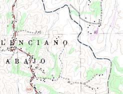
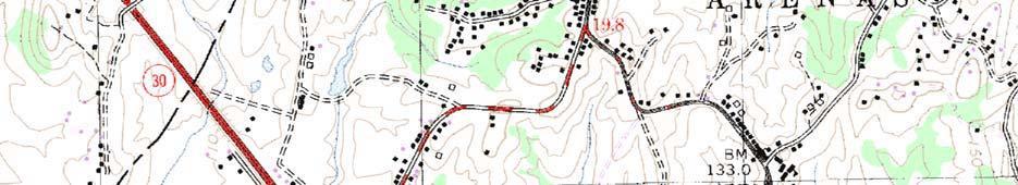
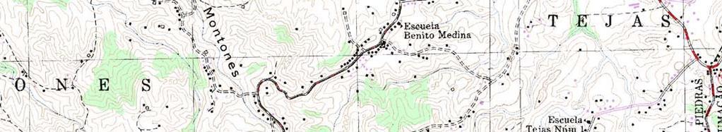
26 II. PROJECT BACKGROUND Location The project site for Estancias de Los Artesanos is located in Montones ward, in the Municipality of Las Piedras. The project site can be accessed by state roads PR-183 and the PR-30. A future highway PR-204 is planned to be constructed by the Highway & Transportation Authority. The future PR-204 crosses the project site and connects the PR-30 with the PR-183. The project consists on 488 single family units and 126 walk ups. The total area of the project is approximately 118 acres to be developed in four phases. Figure 1, shows the location of the site in the USGS quadrangle. Figure 3 shows a layout of the proposed project. Site description and Topography In existing condition, the project area and its vicinities are covered mainly by pasture and scattered bushes. Most of the site is sloped from 10 up to 60 percent and drains toward the Quebrada Los Muertos and its unnamed tributary. Only a 30.4 acres portion of the site located at the west drains toward Quebrada Montones. The ground elevation of the site varies between 98.0 and m. (M.S.L.). Figure 9 shows the topography of the site. Water Bodies Quebrada Los Muertos is crossing the project site and runs northward. An unnamed tributary coming from the northeast discharges in Quebrada Los Muertos at the project site. Quebrada Montones runs northward near to the west limit of the project property. These watercourses are tributaries of the Rio Valenciano that subsequently is tributary of the Rio Gurabo. Flooding From the regulatory point of view, the project site is not classified as floodable for a 100-year rainfall event. Figure 5 shows sheet 185B from FEMA s flood map. 3
27 Field Work Field data used in this study was taken by drawings provided by Eng. Jorge Aviles. This field information was used for the hydraulic modeling. Results obtained in this study are strictly based on this information. A certified fieldwork is attached in the pocket at the end of this study as Appendix I. Former Studies This office found no previous H/H studies for the area under study. So, all the information gathered for the study was through site inspection and interviews of neighboring residents. Study Level This study is intended as an aid to the design engineer in the preparation of the construction drawings for the recommended structures. Figures, schematics and drawings must not be used as construction drawings. The design engineer must elaborate the construction drawings in agreements with the recommendations of this study. 4
28 III. HYDROLOGIC ANALYSIS Methodology The computer program entitled Flood Hydrograph Package (HEC-1) developed by the U.S. Army Corps of Engineers [1990] was used for the hydrologic analysis. Using this program, the Unit Hydrograph method and the Runoff Curve Number (CN) method, both developed by the Soil Conservation Service (SCS), were applied to determine the design hydrograph. This was computed by a process of translating the rainfall excess into a runoff hydrograph known as convolution. Peak discharges ranging in frequencies from 2-, 10-, 25-, 50- and 100-year were estimated for the existing and proposed condition. Drainage Areas and Runoff Pattern At existing condition, four onsite drainage areas were defined. The onsite areas were named: P1 (30.4 acres), P2 (40.6 acres), P3 (18.1 acres) and P4 (28.9 acres). Only Area P1 discharge toward Quebrada Montones, areas P2, P3 and P4 drain to Quebrada Los Muertos. In addition, for the hydraulic analysis to determine the water levels of Quebrada Los Muertos, two offsite areas were identified: Basin 1 and Basin 2. Basin 1 was subdivided in: Basin 1A (540.6 acres), Basin 1B (710.8 acres) and Basin 1C (60.8 acres). Basin 1C belongs to the property of La Campiña Development currently under construction. Basin 2 (409.8 acres) belongs to the unnamed tributary of Quebrada Los Muertos. Figure 2 shows a portion of the USGS quadrangle of Juncos with the watershed delineation for existing condition including. In proposed condition, the magnitude of the onsite drainage areas were resized keeping the pattern established in existing condition. The only significant change was the reduction of Area P1 to 24 acres and the consequent increase of Area P2 (47 acres). Figure 3 shows the proposed development layout and the proposed drainage areas. 5
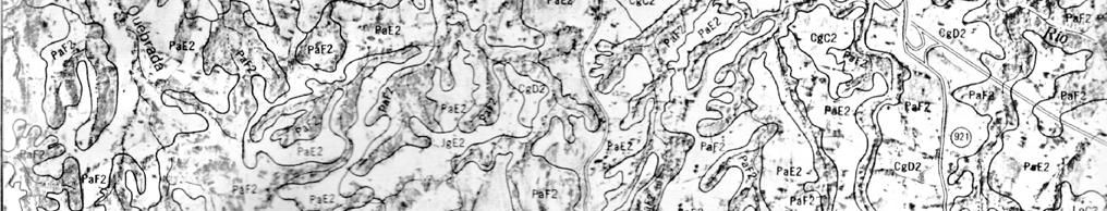
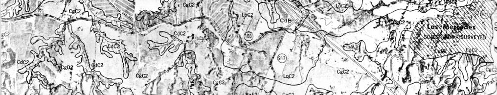
29 Table 1 shows a comparison of the magnitude of the drainage areas for existing and proposed condition. Curve Numbers PROJECT SITE OFFSITE Table 1 Drainage Areas Area ID Area, Acres Existing Proposed P P P P Basin 1A Basin 1B Basin 1C Basin Curve numbers (CN) were computed using the SCS methodology. For its application the different soil types and land uses were estimated from SCS [1978] and USGS [1982] respectively. Curve numbers were established for Antecedent Moisture Condition II. The soil survey shows five soils type classified as candelero loam, cayagua sandy loam, jagueyes loam, lirios clay loam and pandura loam. Figure 4 shows the portion of the soil map corresponding to the watersheds and project area. Appendix A shows the physiographic characteristics of the watersheds and the CN calculations. Lag Time The Lag Time (T Lag ) was estimated using the SCS method defined as: T Lag = L 0.8 (S+1) Y 0.5 where : L = channel length (ft) S = 1000/CN - 10 Y = average watershed slope Detailed Lag Time calculation is shown in Appendix A. 6
30 Rainfall Data The variation of rainfall volume with time was required as part of the storm input for the SCS Curve Number method. Therefore, the development of a design storm with a rainfall frequency and duration was necessary to compute the design hydrograph for the watershed. Rainfall data used in this study was obtained from the Technical Paper No. 42 (TP-42) [National Weather Service, For and 0.25 hrs. duration, the precipitation was obtained from a regression analysis. Appendix A includes a spreadsheet with these calculations. The rainfall event of 2, 10, 25, 50 and 100-years frequency and different durations are shown in Table 2. Depth-Area Adjustment Table 2 Rainfall for 2, 10, 25, 50 and 100 years Precipitation Duration Inches Hrs. 2-yr 10-yr 25-yr 50-yr 100-yr Point rainfall estimates obtained from the TP-42 represent values for areas up to 10 mi 2 ; therefore, a depth-area adjustment should be applied to the rainfall data when the watershed area is greater. In this case, the largest watershed is approximate 1.11 mi 2. Hence, this adjustment was not applied. Time Distribution of Rainfall The triangular type methodology was used to distribute the rainfall depth in time. This method is considered acceptable for small areas. 7
31 Rainfall Extraction Rainfall extraction such as the vegetative interception, the depressional storage, and the infiltration were estimated using the SCS's Runoff Curve Number method. Though this method is used to predict runoff volume directly, the rainfall extraction is incorporated in the model as function of the curve number of the watershed. Hydrologic Analysis for the Project Site Following HEC-1 methodology, hydrographs were determined for existing and proposed condition for the project site to evaluate the impact of the development expressed in a runoff increase. Input and output data for the HEC-1 model are included in Appendix B for Existing Condition and Appendix C for Proposed Condition. Table 3 shows the results for these conditions in the next page. Table 3 Peak Discharges for 2-, 10-, 25-, 50- and 100-yr frequencies Condition Description Area Existing Condition Proposed Condition Peak Discharge, cfs 2-yr 10-yr 25-yr 50-yr 100-yr Discharging to Quebrada Montones P Discharging to Quebrada Los Muertos P P P COMB (P2+P3+P4) Discharging to Quebrada Montones P P Discharging to P Quebrada Los Muertos P COMB (P2+P3+P4) From the inspection of Table 3, the peak for the combined discharge toward Quebrada Los Muertos in proposed condition is higher than that of the existing condition. The increment in discharge has to be mitigated as required by Puerto Rico Planning Board Regulation No. 3. Discharge from area P1 at proposed condition was maintained similar to the peak of the existing 8
32 condition. This indicates that the discharge toward Quebrada Montones do not increase despite of the development. That was ensured with the area reduction of the drainage area for proposed condition. Hydrologic Analysis for Quebrada Los Muertos An additional hydrological analysis was performed to determine the peak discharge for Quebrada Los Muertos and its unnamed tributary crossing the project site. This analysis includes the incorporation of the offsite and the onsite areas. Table 4 shows the results of this analysis. Table 4 Peak Discharges for 100-yr frequency Description 100-yr peak Discharge, cfs Basin 1 (Quebrada Los Muertos upstream merging point) 4,238 Basin 2 (Unnamed tributary) 1,663 Combined (Quebrada Los Muertos downstream merging point) 5,845 9
33 IV. MITIGATION The development of the site will increase the runoff discharge. The Puerto Rico Planning Board Regulation No. 3 requires a flow mitigation structure wherever an increase in discharge is produced. Therefore, a detention analysis is required in the project. Methodology The computer program HEC-1 provides means for modeling detention structures. The purpose of detention is that the proposed condition peak discharge does not exceed the existing condition peak discharge. Two detention structures will be included in the project. The detention structures will be located in areas P2 (Pond #1) and P4 (Pond #2). Then, a peak reduction is expected in the combined discharge toward Quebrada Los Muertos. See Figure 6 for schematic layout of the project and the location of the detention ponds. Depth-Volume Relations Depth to volume relationships for the detention ponds have been calculated as a function of the bank slope of 1V:2H. Base area of the each pond was set at 2,500 and 1,225 square meters for Area P2 and P4 respectively. Appendix D includes a spreadsheet with the depth-volume relation computations. Flow Depth Relations Pond #1 outlet control structure will consist on a battery of two (2) 42 diameter orifices and a 2.0-meter wide rectangular weir located 2.25 meters above the pond bottom. Pond #2 outlet control structure will consist on a battery of two (2) 33 diameter orifices and a 6.0-meter wider rectangular weir located 2.25 meters over the pond bottom. Flow through the orifices was computed using Torricelli s formula. Appendix D shows the computations and the curve. 10
34 Results The results of the mitigation analysis show that the proposed detention structures provide the appropriate holding for feeding into the downstream the 100-year frequency peak discharge from the combined project site. Mitigation for more recurrent storm events was also found appropriate. Results are shown in Table 5. Input and output data for the HEC-1 model for mitigation are included in Appendix E Table 5 Mitigation Analysis Results Comparison Condition Existing Proposed Proposed w/mitigation Area Peak Discharge, cfs 2-yr 10-yr 25-yr 50-yr 100-yr P P P COMB (P2+P3+P4) P P P COMB (P2+P3+P4) P2 (Mitigated) P P4 (Mitigated) COMB (P2*+P3+P4*) Mitigation Structure Dimensions and Accessories Final dimensions for the discharge detention ponds will include a minimum free board of 0.30 meters. Figure 7 and 8 show the schematic layout and the schematic sections of the ponds. Consequently, the ponds will have the dimensions shown in Table 6. 11
35 Table 6 Detention Ponds Characteristics Pond Dimensions Base Area 2,500 m 2 Height 2.80 m Bank Slope 1V:2H POND #1 bottom 2-42 ø Outlet Structure Rectangular 2.25 Emergency Weir 2.50 over bottom 2.0 m 4.0 m Pond Outlet Concrete Pipes 2-54 ø Pond Dimensions Base Area 1,225 m 2 Height 2.75 m Bank Slope 1V:2H POND #2 bottom 2-33 ø Outlet Structure Rectangular 2.25 Emergency Weir 2.45 over bottom 6.0 m 4.00 m Pond Outlet Concrete Pipe 60 ø The bottom geometry of the ponds have been considered as square for the mitigation analysis; but another shape can be used as well if the magnitude of the area is maintained. 12
36 V. HYDRAULIC ANALYSIS The hydraulic analysis was made using the mathematical model HEC-RAS developed by the US Corps of Engineers. For this model, the hydraulic regime is steady, uniform, and one-dimensional. The model accepts changes in the geometry of the watercourse, bank-bed-overbank friction coefficient and shapes of hydraulic structures. The friction coefficient used in the modeling was obtained from visual inspection of the watercourses bed and banks; and crosschecked with the typical values provided by Barnes (1967) and Chow (1959). Cross sections for the water course were provided by Eng. Jorge Aviles. The field work is included in Appendix I. Roughness Manning coefficients estimated for the model are from for concrete to for the natural watercourse. These values reflect the changes in direction and the irregular shape of the channel bed, and the vegetation present in the courses. Contraction and Expansion Coefficients Coefficients of contraction and expansion used are those recommended by the HEC-RAS user s manual. Thus, coefficients of 0.1 and 0.3 respectively were used for gradual transitions. Hydraulics for Existing Condition At existing condition, the topography defines the course of Quebrada Los Muertos passing across the project property from south to northwest. The length of this watercourse crossing the property is approximately 800 meters. Ten (10) cross sections were used to model the existing condition. This condition includes the bridge of the new Puerto Rico Highway Authority s PR- 30 and PR-183 connector that crosses the project property. In addition, an unnamed tributary 13
37 running from northeast to southwest is discharging to Quebrada Los Muertos. Five cross sections more were included to model this watercourse. Figure 9 shows the location of the cross sections and the nomenclature used in the HEC-RAS modeling. The computer output for this condition is included in Appendix G. The following Table 7 includes the summary of the results. Table 7 Existing Condition Hydraulics 100-yr flow River Sta Profile Q Total Min Ch El W.S. Elev Crit W.S. E.G. Elev E.G. Slope Vel Chnl Flow Area Top Width Froude # Chl (m3/s) (m) (m) (m) (m) (m/m) (m/s) (m2) (m) yr yr yr yr yr yr yr yr yr yr yr Bridge yr yr yr yr yr yr Hydraulics for Proposed Condition At proposed condition, a new m span bridge will be necessary over the unnamed tributary. This condition included the new structure located between cross sections 14 and 15. Figure 6 shows the layout of the project and the location of the new bridge. The computer output for this condition is included in Appendix H. The following Table 8 includes the summary of the results 14
38 Table 8 Proposed Condition Hydraulics 100-yr flow River Sta Profile Q Total Min Ch El W.S. Elev Crit W.S. E.G. Elev E.G. Slope Vel Chnl Flow Area Top Width Froude # Chl (m3/s) (m) (m) (m) (m) (m/m) (m/s) (m2) (m) yr yr Bridge yr yr yr yr yr yr yr yr yr yr yr Bridge yr yr yr yr yr yr Floodplain delineation for Quebrada Los Muertos The results of the hydraulic analysis were used to delineate the 100-yr floodplain of Quebrada Los Muertos. The proposed development will not impact the natural watercourse and leave unmodified the bed and banks of the existing condition. Figure 9 shows the flood plain delineation for the existing condition. 15
39 VI. CONCLUSIONS AND RECOMMENDATIONS The following are the conclusions of this study: 1. According to the regulatory flood maps, the project site is not considered floodable for the 100-year rainfall event 2. Existing condition runoff peak discharge to Quebrada Los Muertos is lower that that of the proposed condition. Mitigation is needed. 3. The reduction of the onsite Area P1 for proposed condition prevents an increase of the peak discharge due to development of the site toward Quebrada Montones. 4. Mitigation reduces the 100-year discharge for proposed condition from 713 to 530 cfs for the entire project property draining to Quebrada Los Muertos. This value is lower than the existing condition peak flow of 655. Recurrent discharges were also mitigated. 5. Either proposed bridge over the unnamed tributary do not increase the water levels over the allowed by the PR Planning Board Regulation No. 13. The following are the recommendations of this study: 1. Two detention ponds will be required to mitigate the runoff increase. Mitigation structures will have the dimensions and accessories indicated in Table 6 of this report. 2. Exit headwalls must be provided. Rip-rap shall be placed at the exit of the outlet of the mitigation ponds. 3. It is very important to prepare a long-term maintenance plan, which should include the proposed culvert, the pond outlet structure and the receiving storm system inspection after each significant discharge events. Damages, if any, must be repaired promptly and properly. 16
40 Study Limits All the recommendations specified in this study must be considered to assure the optimum performance of the proposed discharge mitigation pond and the receiving stream. The design engineer will be responsible for elaborating the drawings in conformance with the recommendations of this study. The results of this study are based on free flow conditions through the hydraulic structures. Proper maintenance must be developed to assure this condition. On the event of the occurrence of any severe obstruction to the flow, the results and recommendations may be impaired. Finally, results and recommendations included in this report must be used only and exclusively by the design engineer for the intended purposes as indicated in this study. 17
41 VII. BIBLIOGRAPHY National Weather Service, Generalized Estimates of Probable Maximum Precipitation and Rainfall Frequency Data for Puerto Rico and Virgin -Islands. Technical Paper No. 42. U.S. Department of Commerce. Washington, D.C. P.R. Planning Board, Reglamento sobre Zonas Susceptibles a Inundaciones. Reglamento de Planificación Número 13. Estado Libre Asociado de Puerto Rico, Oficina del Gobernador. Soil Conservation Service, Soil Survey of Humacao Area of Eastern Puerto Rico Puerto Rico. U.S. Department of Agriculture. U.S. Army Corps of Engineers, Flood Hydrograph Package (HEC-1), User's Manual. Hydrologic Engineering Center. Davis, California. 18
42 TABLE OF CONTENTS TABLE OF CONTENTS... i LIST OF FIGURES...iii LIST OF APPENDIXES...iii I. INTRODUCTION... 1 Purpose of Study... 1 Authorization... 2 Approach... 2 II. PROJECT BACKGROUND... 3 Location... 3 Site description and Topography... 3 Water Bodies... 3 Flooding... 3 Field Work... 4 Former Studies... 4 Study Level... 4 III. HYDROLOGIC ANALYSIS... 5 Methodology... 5 Drainage Areas and Runoff Pattern... 5 Curve Numbers... 6 Lag Time... 6 Rainfall Data... 7 Depth-Area Adjustment... 7 Time Distribution of Rainfall... 7 Rainfall Extraction... 8 Hydrologic Analysis for the Project Site... 8 Hydrologic Analysis for Quebrada Los Muertos... 9 IV. MITIGATION Methodology i
43 Depth-Volume Relations Flow Depth Relations Results Mitigation Structure Dimensions and Accessories V. HYDRAULIC ANALYSIS Roughness Contraction and Expansion Coefficients Hydraulics for Existing Condition Hydraulics for Proposed Condition Floodplain delineation for Quebrada Los Muertos VI. CONCLUSIONS AND RECOMMENDATIONS Study Limits VII. BIBLIOGRAPHY...18 ii
44 LIST OF FIGURES FIGURE 1. FIGURE 2. FIGURE 3. FIGURE 4. FIGURE 5. FIGURE 6. FIGURE 7. FIGURE 8. FIGURE 9. Location Map Existing Condition Watershed Limit Development Layout and Proposed Drainage Areas Soils Map FEMA s Flood Insurance Rate Map Proposed Structures Layout Mitigation Pond Schematics for Area P2 Mitigation Pond Schematics for Area P4 Topography and Cross Sections for Existing Condition LIST OF APPENDIXES APPENDIX A. APPENDIX B. APPENDIX C. APPENDIX D. APPENDIX E. APPENDIX F. APPENDIX G. APPENDIX H. APPENDIX I. Hydrologic Parameters Estimation HEC-1 Results for Existing Condition HEC-1 Results for Proposed Condition Depth-Volume and Depth-Flow Computations HEC-1 Results for Mitigation Analysis HEC-1 Results for Quebrada Los Muertos HECRAS Results for Existing Condition HECRAS Results for Proposed Condition Field Work iii
45 FIGURES


46


47
48


49
50
51
52
53
54
HYDROLOGIC-HYDRAULIC STUDY BAYAMON SOUTH COMMERCIAL CENTER BAYAMON, PUERTO RICO. Casiano Ancalle, P.E. August, 2006 I.
 HYDROLOGIC-HYDRAULIC STUDY BAYAMON SOUTH COMMERCIAL CENTER BAYAMON, PUERTO RICO Casiano Ancalle, P.E. August, 2006 I. INTRODUCTION A commercial development project named Bayamon South Commercial Center
HYDROLOGIC-HYDRAULIC STUDY ISABELLA OCEAN RESIDENCES ISLA VERDE, CAROLINA, PR
 HYDROLOGIC-HYDRAULIC STUDY ISABELLA OCEAN RESIDENCES ISLA VERDE, CAROLINA, PR 1 INTRODUCTION 1.1 Project Description and Location Isabella Ocean Residences is a residential development to be constructed
Hydraulic Report. County Road 595 Bridge over Mulligan Creek. Prepared By AECOM Brian A. Hintsala, P.E
 Prepared for: Prepared by: Marquette County Road Commission AECOM Ishpeming, MI Marquette, MI 60240279 December 9. 2011 Hydraulic Report County Road 595 Bridge over Mulligan Creek Prepared By AECOM Brian
Hydraulic Report. County Road 595 Bridge over Dead River. Prepared By AECOM Brian A. Hintsala, P.E
 Prepared for: Prepared by: Marquette County Road Commission AECOM Ishpeming, MI Marquette, MI 60240279 December 9, 2011 Hydraulic Report County Road 595 Bridge over Dead River Prepared By AECOM Brian A.
CLAY STREET BRIDGE REPLACEMENT
 HYDROLOGY /HYDRAULICS REPORT. EL DORADO COUNTY CLAY STREET BRIDGE REPLACEMENT Prepared by: Joseph Domenichelli Domenichelli & Associates 1107 Investment Blvd., Suite 145 El Dorado Hills, California 95762
INFLOW DESIGN FLOOD CONTROL SYSTEM PLAN 40 C.F.R. PART PLANT YATES ASH POND 3 (AP-3) GEORGIA POWER COMPANY
 GEORGIA POWER COMPANY") INFLOW DESIGN FLOOD CONTROL SYSTEM PLAN 40 C.F.R. PART 257.82 PLANT YATES ASH POND 3 (AP-3) GEORGIA POWER COMPANY EPA s Disposal of Coal Combustion Residuals from Electric Utilities Final Rule (40 C.F.R.
INFLOW DESIGN FLOOD CONTROL SYSTEM PLAN 40 C.F.R. PART 257.82 PLANT YATES ASH POND 3 (AP-3) GEORGIA POWER COMPANY EPA s Disposal of Coal Combustion Residuals from Electric Utilities Final Rule (40 C.F.R.
SAW MILL RIVER DAYLIGHTING ANALYSIS AT RIVER PARK CENTER
 SAW MILL RIVER DAYLIGHTING ANALYSIS AT RIVER PARK CENTER Prepared for: Struever Fidelco Cappelli LLC McLaren Project No. 6 August 28 TABLE OF CONTENTS. INTRODUCTION 2. SAW MILL RIVER: FEMA STUDY... 2..
INFLOW DESIGN FLOOD CONTROL SYSTEM PLAN 40 C.F.R. Part PLANT MCINTOSH ASH POND 1 GEORGIA POWER COMPANY
 INFLOW DESIGN FLOOD CONTROL SYSTEM PLAN 40 C.F.R. Part 257.82 PLANT MCINTOSH ASH POND 1 GEORGIA POWER COMPANY EPA s Disposal of Coal Combustion Residuals from Electric Utilities Final Rule (40 C.F.R. Part
BMP Design Aids. w w w. t r a n s p o r t a t i o n. o h i o. g o v. Equations / Programs
 BMP Design Aids 1 Equations / Programs Outlet Discharge Equations Hydrograph and Pond Routing Programs USGS StreamStats 2 Ohio Department of Transportation 1 Training Intent Introduction and overview of
What is runoff? Runoff. Runoff is often defined as the portion of rainfall, that runs over and under the soil surface toward the stream
 What is runoff? Runoff Runoff is often defined as the portion of rainfall, that runs over and under the soil surface toward the stream 1 COMPONENTS OF Runoff or STREAM FLOW 2 Cont. The types of runoff
INFLOW DESIGN FLOOD CONTROL SYSTEM PLAN PLANT BARRY ASH POND ALABAMA POWER COMPANY
 INFLOW DESIGN FLOOD CONTROL SYSTEM PLAN PLANT BARRY ASH POND ALABAMA POWER COMPANY Section 257.82 of EPA s regulations requires the owner or operator of an existing or new CCR surface impoundment or any
Jacobi, Toombs, and Lanz, Inc.
 Area 5: Blackiston Mill Road at Dead Man's Hollow Flooding Assessment Jacobi, Toombs, and Lanz, Inc. This document summarizes an assessment of drainage and flooding concerns and provides recommendations
Hydrologic Study Report for Single Lot Detention Basin Analysis
 Hydrologic Study Report for Single Lot Detention Basin Analysis Prepared for: City of Vista, California August 18, 2006 Tory R. Walker, R.C.E. 45005 President W.O. 116-01 01/23/2007 Table of Contents Page
INFLOW DESIGN FLOOD CONTROL SYSTEM PLAN PLANT GASTON GYPSUM POND ALABAMA POWER COMPANY
 INFLOW DESIGN FLOOD CONTROL SYSTEM PLAN PLANT GASTON GYPSUM POND ALABAMA POWER COMPANY Section 257.82 of EPA s regulations requires the owner or operator of an existing or new CCR surface impoundment or
INITIAL RUN-ON AND RUN-OFF CONTROL PLAN 40 C.F.R. PART 257
 INITIAL RUN-ON AND RUN-OFF CONTROL PLAN 40 C.F.R. PART 257.81 HUFFAKER ROAD (PLANT HAMMOND) PRIVATE INDUSTRIAL LANDFILL (HUFFAKER ROAD LANDFILL) GEORGIA POWER COMPANY EPA s Disposal of Coal Combustion
Hydromodification Management Measures
 Chapter 7 Hydromodification Management Measures This Chapter summarizes the requirements for controlling erosive flows from development projects. 7.1 Why Require Hydromodification Management? Changes in
Hydromodification Management Measures
 Chapter 7 Hydromodification Management Measures This Chapter summarizes the requirements for controlling erosive flows from development projects. 7.1 Why Require Hydromodification Management? Changes in
SECTION IV WATERSHED TECHNICAL ANALYSIS
 A. Watershed Modeling SECTION IV WATERSHED TECHNICAL ANALYSIS An initial step in the preparation of this stormwater management plan was the selection of a stormwater simulation model to be utilized. It
INFLOW DESIGN FLOOD CONTROL SYSTEM PLAN PLANT GREENE COUNTY ASH POND ALABMA POWER COMPANY
 INFLOW DESIGN FLOOD CONTROL SYSTEM PLAN PLANT GREENE COUNTY ASH POND ALABMA POWER COMPANY Section 257.82 of EPA s regulations requires the owner or operator of an existing or new CCR surface impoundment
LAKE COUNTY HYDROLOGY DESIGN STANDARDS
 LAKE COUNTY HYDROLOGY DESIGN STANDARDS Lake County Department of Public Works Water Resources Division 255 N. Forbes Street Lakeport, CA 95453 (707)263-2341 Adopted June 22, 1999 These Standards provide
5/25/2017. Overview. Flood Risk Study Components HYDROLOGIC MODEL (HEC-HMS) CALIBRATION FOR FLOOD RISK STUDIES. Hydraulics. Outcome or Impacts
 CALIBRATION FOR FLOOD RISK STUDIES. Hydraulics. Outcome or Impacts") HYDROLOGIC MODEL (HEC-HMS) CALIBRATION FOR FLOOD RISK STUDIES C. Landon Erickson, P.E.,CFM Water Resources Engineer USACE, Fort Worth District April 27 th, 2017 US Army Corps of Engineers Overview Flood
HYDROLOGIC MODEL (HEC-HMS) CALIBRATION FOR FLOOD RISK STUDIES C. Landon Erickson, P.E.,CFM Water Resources Engineer USACE, Fort Worth District April 27 th, 2017 US Army Corps of Engineers Overview Flood
Development of a Stage-Discharge Rating for Site Van Bibber Creek at Route 93
 Development of a Stage-Discharge Rating for Site 330 - Van Bibber Creek at Route 93 Prepared for: Urban Drainage and Flood Control District 2480 W. 26 th Avenue Suite 156-B Denver, CO 80211 May 19, 2006
Prepared for: City of Jeffersonville. November Prepared by
 JEFFERSONVILLE STORMWATER MASTER PLAN HYDRAULICS APPENDIX JEFFERSONVILLE, INDIANA Prepared for: City of Jeffersonville November 2011 Prepared by Christopher B. Burke Engineering, Ltd. 115 W. Washington
MIDAS CREEK PROJECT. FINAL DESIGN REPORT SKR Hydrotech 4/11/2012
 2012 MIDAS CREEK PROJECT FINAL DESIGN REPORT SKR Hydrotech 4/11/2012 Executive Summary... 1 Section 1 Introduction... 1 Background Information... 1 Purpose of Study... 1 Scope of Work... 1 Section 2 Description
DRAINAGE STUDY CROWS LANDING INDUSTRIAL BUSINESS PARK. Stanislaus County. Prepared by:
 DRAINAGE STUDY FOR CROWS LANDING INDUSTRIAL BUSINESS PARK Stanislaus County Prepared by: March, 2017 Revised November, 2017 Table of Contents EXECUTIVE SUMMARY... 1 1. INTRODUCTION... 2 2. HYDROLOGY...
UPDATE OF ARC TP108 RUN-OFF CALCULATION GUIDELINE
 UPDATE OF ARC TP108 RUN-OFF CALCULATION GUIDELINE Bodo Hellberg, Stormwater Action Team, Auckland Regional Council Matthew Davis, Stormwater Action Team, Auckland Regional Council ABSTRACT This paper focuses
Flood Risk Analysis of Bridge A Case Study
 ISBN 978-93-84468-11-8 Proceedings of International Conference on Architecture And Civil Engineering (ICAACE'14) Dubai, December 25-26, 2014, pp. 128-134 Flood Risk Analysis of Bridge A Case Study Safa
Culvert Sizing procedures for the 100-Year Peak Flow
 CULVERT SIZING PROCEDURES FOR THE 100-YEAR PEAK FLOW 343 APPENDIX A: Culvert Sizing procedures for the 100-Year Peak Flow A. INTRODUCTION Several methods have been developed for estimating the peak flood
Drainage Analysis. Appendix E
 Drainage Analysis Appendix E The existing and proposed storm drainage systems have been modeled with Bentley CivilStorm V8 computer modeling software. The peak stormwater discharge was determined for
SECTION III: WATERSHED TECHNICAL ANALYSIS
 Trout Creek Watershed Stormwater Management Plan SECTION III: WATERSHED TECHNICAL ANALYSIS A. Watershed Modeling An initial step this study of the Trout Creek watershed was the selection of a stormwater
RETENTION BASIN EXAMPLE
 -7 Given: Total Tributary Area = 7.5 ac o Tributary Area within Existing R/W = 5.8 ac o Tributary Area, Impervious, Outside of R/W = 0.0 ac o Tributary Area, Pervious, Outside of R/W = 1.7 ac o Tributary
APPENDIX H. Draft Storm Drainage Master Plan
 APPENDIX H Draft Storm Drainage Master Plan Folsom Sphere of Influence (SOI) DRAFT Storm Drainage Masterplan Prepared for: MacKay & Somps Civil Engineering, Inc. Prepared By: DOMENICHELLI & ASSOCIATES
CVEN 339 Summer 2009 Final Exam. 120 minutes allowed. 36 Students. No curve applied to grades. Median 70.6 Mean 68.7 Std. Dev High 88 Low 24.
 CVEN 339 Final Exam 120 minutes allowed 36 Students No curve applied to grades Median 70.6 Mean 68.7 Std. Dev. 13.7 High 88 Low 24.5 Name: CVEN 339 Water Resources Engineering Summer Semester 2009 Dr.
INFLOW DESIGN FLOOD CONTROL SYSTEM PLAN 40 C.F.R. PART PLANT YATES ASH POND B (AP-B ) GEORGIA POWER COMPANY
 GEORGIA POWER COMPANY") INFLOW DESIGN FLOOD CONTROL SYSTEM PLAN 40 C.F.R. PART 257.82 PLANT YATES ASH POND B (AP-B ) GEORGIA POWER COMPANY EPA s Disposal of Coal Combustion Residuals from Electric Utilities Final Rule (40 C.F.R.
INFLOW DESIGN FLOOD CONTROL SYSTEM PLAN 40 C.F.R. PART 257.82 PLANT YATES ASH POND B (AP-B ) GEORGIA POWER COMPANY EPA s Disposal of Coal Combustion Residuals from Electric Utilities Final Rule (40 C.F.R.
State Standard. for. Stormwater Detention/Retention
 ARIZONA DEPARTMENT OF WATER RESOURCES FLOOD MITIGATION SECTION State Standard for Stormwater Detention/Retention Under the authority outlined in ARS 48-3605(a) the Director of the Arizona Department of
Technical Memorandum
 Tucson Office 3031 West Ina Road Tucson, AZ 85741 Tel 520.297.7723 Fax 520.297.7724 www.tetratech.com Technical Memorandum To: Kathy Arnold From: Greg Hemmen, P.E. Company: Rosemont Copper Company Date:
INITIAL RUN-ON AND RUN-OFF CONTROL PLAN 40 C.F.R. PART 257
 INITIAL RUN-ON AND RUN-OFF CONTROL PLAN 40 C.F.R. PART 257.81 PLANT BOWEN PRIVATE INDUSTRY SOLID WASTE DISPOSAL FACILITY (ASH LANDFILL) GEORGIA POWER COMPANY EPA s Disposal of Coal Combustion Residuals
INITIAL INFLOW DESIGN FLOOD CONTROL SYSTEM PLAN PLANT MCMANUS ASH POND A (AP-1) 40 CFR
 40 CFR") INITIAL INFLOW DESIGN FLOOD CONTROL SYSTEM PLAN PLANT MCMANUS ASH POND A (AP-1) 40 CFR 257.82 EPA s Disposal of Coal Combustion Residuals from Electric Utilities Final Rule (40 C.F.R. Part 257 and Part
INITIAL INFLOW DESIGN FLOOD CONTROL SYSTEM PLAN PLANT MCMANUS ASH POND A (AP-1) 40 CFR 257.82 EPA s Disposal of Coal Combustion Residuals from Electric Utilities Final Rule (40 C.F.R. Part 257 and Part
TABLE OF CONTENTS. 1.0 Background Watershed Description Hydrology - HEC-HMS Models Hydraulics - HEC-RAS Models...
 TABLE OF CONTENTS 1.0 Background... 1 2.0 Watershed Description... 1 3.0 Hydrology - HEC-HMS Models... 2 3.1 Hydrologic Approach... 2 3.2 Drainage Areas... 2 3.3 Curve Numbers... 2 3.4 Lag Times... 3 3.5
PRELIMINARY HYDROLOGY/HYDRAULICS ANALYSES RESULTS
 PRELIMINARY HYDROLOGY/HYDRAULICS ANALYSES RESULTS Coldstream Park Stream Corridor Restoration and Preservation Consent Decree SEP Prepared for Lexington-Fayette Urban County Government Division of Water
DRAINAGE REPORT. Project Name: PG&E Gas Operations Technical Training Center Winters, CA. Date: February 4, Prepared by: BKF Engineers
 DRAINAGE REPORT Project Name: PG&E Gas Operations Technical Training Center Winters, CA Date: February 4, 2015 Prepared by: BKF Engineers Client: Pacific Gas & Electric Company This report has been prepared
Project Drainage Report
 Design Manual Chapter 2 - Stormwater 2A - General Information 2A-4 Project Drainage Report A. Purpose The purpose of the project drainage report is to identify and propose specific solutions to stormwater
LIST OF TABLES... ii LIST OF FIGURES... iii LIST OF APPENDICES... iv. Section 1 - Introduction Purpose of Study... 1
 Preliminary Hydrologic Analysis for Alberhill Villages April 2015 TABLE OF CONTENTS Section Name Page Number LIST OF TABLES... ii LIST OF FIGURES... iii LIST OF APPENDICES... iv Section 1 - Introduction...
SECTION 4 STORM DRAINAGE
 4.01 GENERAL SECTION 4 STORM DRAINAGE These standards shall provide minimum requirements for the design of Storm Drainage and related appurtenances within the City of West Sacramento rights of way and
Dawson County Public Works 25 Justice Way, Suite 2232, Dawsonville, GA (706) x 42228
 x 42228") Dawson County Public Works 25 Justice Way, Suite 2232, Dawsonville, GA 30534 (706) 344-3500 x 42228 DAWSON COUNTY STORM WATER REVIEW CHECKLIST Project Name: Property Address: Engineer: Fax #/Email: Date:
Dawson County Public Works 25 Justice Way, Suite 2232, Dawsonville, GA 30534 (706) 344-3500 x 42228 DAWSON COUNTY STORM WATER REVIEW CHECKLIST Project Name: Property Address: Engineer: Fax #/Email: Date:
PRELIMINARY DRAINAGE REPORT NEWCASTLE FIRE STATION OLD STATE HIGHWAY
 PRELIMINARY DRAINAGE REPORT FOR THE NEWCASTLE FIRE STATION OLD STATE HIGHWAY PREPARED FOR THE NEWCASTLE FIRE PROTECTION DISTRICT JULY 2014 BY ROSEVILLE DESIGN GROUP, INC. ROSEVILLE DESIGN GROUP, Inc Established
IMPROVED MODELING OF THE GREAT PEE DEE RIVER: DOCUMENTATION IN SUPPORT OF FEMA APPEAL. Horry County, South Carolina
 IMPROVED MODELING OF THE GREAT PEE DEE RIVER: DOCUMENTATION IN SUPPORT OF FEMA APPEAL Horry County, South Carolina July 15, 2016 CONTENTS 1 Introduction... 2 2 Hydrology... 3 3 HEC-RAS Model... 7 3.1 Cross
Appendix C, Attachment 4 June 11, Diversion Channel Outlet Hydraulic Modeling RAS and ADH
 Diversion Channel Outlet Hydraulic Modeling RAS and ADH 11 June 2012 1 Contents Introduction... 3 HEC-RAS modeling of Outlet... 3 Transition Structure Geometry... 3 ADH Modeling of Outlet and Floodplain...
Hydrotechnical Design Guidelines for Stream Crossings
 Hydrotechnical Design Guidelines for Stream Crossings Introduction Design of stream crossings and other in-stream highway facilities requires estimation of design highwater elevation and mean channel velocity.
Learn how to design inlet grates, detention basins, channels, and riprap using the FHWA Hydraulic Toolbox and WMS
 v. 11.0 WMS 11.0 Tutorial Learn how to design inlet grates, detention basins, channels, and riprap using the FHWA Hydraulic Toolbox and WMS Objectives Learn how to use several Hydraulic Toolbox calculators
APPENDIX F RATIONAL METHOD
 7-F-1 APPENDIX F RATIONAL METHOD 1.0 Introduction One of the most commonly used procedures for calculating peak flows from small drainages less than 200 acres is the Rational Method. This method is most
Detention Pond Design Considering Varying Design Storms. Receiving Water Effects of Water Pollutant Discharges
 Detention Pond Design Considering Varying Design Storms Land Development Results in Increased Peak Flow Rates and Runoff Volumes Developed area Robert Pitt Department of Civil, Construction and Environmental
Alternatives for Willow Creek Flood Mitigation Study
 Alternatives for Willow Creek Flood Mitigation Study Presented by: Anil Tangirala, PE, CFM, ENV SP ms consultants, inc. June 22, 2016 Presentation Overview Introduction Project Background Willow Creek
PRELIMINARY DRAINAGE STUDY
 PRELIMINARY DRAINAGE STUDY For 34 th & J Residences 3402 J St. San Diego, CA 92102 A.P.N 545-250-08 Prepared By: Kenneth J. Discenza, P.E. Site Design Associates, Inc. 1016 Broadway, Suite A El Cajon,
SOUTHEAST TEXAS CONTINUING EDUCATION
 EXAM No. 118 FLOOD - RUNOFF ANALYSIS 1. Information gained from flood - runoff analysis includes which one: A. Stage, discharge, volume. B. Measure depth, volume. C. Velocity, depth, storm occurrence.
HYDROLOGY STUDY PREPARED FOR: MARKHAM PERRIS LLC 302 WEST FIFTH STREET, SUITE 103 SAN PEDRO, CA (310) FOR THE PROJECT:
 FOR THE PROJECT:") HYDROLOGY STUDY PREPARED FOR: MARKHAM PERRIS LLC 302 WEST FIFTH STREET, SUITE 103 SAN PEDRO, CA 90731 (310) 241-2992 FOR THE PROJECT: PERRIS VALLEY COMMERCE CENTER BUILDING PERRIS, CALIFORNIA PROJECT NUMBER:
HYDROLOGY STUDY PREPARED FOR: MARKHAM PERRIS LLC 302 WEST FIFTH STREET, SUITE 103 SAN PEDRO, CA 90731 (310) 241-2992 FOR THE PROJECT: PERRIS VALLEY COMMERCE CENTER BUILDING PERRIS, CALIFORNIA PROJECT NUMBER:
Rational Method Hydrological Calculations with Excel COURSE CONTENT
 Rational Method Hydrological Calculations with Excel Harlan H. Bengtson, PhD, P.E. COURSE CONTENT 1. Introduction Calculation of peak storm water runoff rate from a drainage area is often done with the
TABLE OF CONTENTS PART III - MINIMUM DESIGN STANDARDS Section 105 DRAINAGE SYSTEM DESIGN SPECIFICATIONS AND SCOPE 105.1
 TABLE OF CONTENTS PART III - MINIMUM DESIGN STANDARDS Section 105 DRAINAGE SYSTEM DESIGN SECTION TITLE PAGE 105.1. SPECIFICATIONS AND SCOPE 105.1 105.2. METHODS OF ANALYSIS 105.1 105.2.1. Rational Method
Southeast Policy Area Drainage Study
 Southeast Policy Area Drainage Study Prepared for City of Elk Grove January 2014 448-00-12-03 Table of Contents 1.0 Introduction... 1 2.0 Watershed Description... 1 3.0 Drainage Plan Concept... 1 4.0
Reservoir on the Rio Boba
 Reservoir on the Rio Boba Michael J. Burns II Guillermo Bustamante J. James Peterson Executive Summary The National Institute of Water Resources in the Dominican Republic (INDRHI) plans to construct a
Stormwater Management Studies PDS Engineering Services Division ES Policy # 3-01
 Stormwater Management Studies PDS Engineering Services Division Revised Date: 2/28/08 INTRODUCTION The City of Overland Park requires submission of a stormwater management study as part of the development
Appendix H Amanda Estates Drainage Study
 Appendix H Amanda Estates Drainage Study Hunsaker & Associates 2015 Contents 1 Scope... 1 2 Existing Conditions... 1 3 Project Description... 3 4 Methodology... 5 4.1 Hydrology... 5 4.2 Hydraulics...
Chapter Introduction. 5.2 Computational Standard Methods HYDROLOGY
 Chapter 5. HYDROLOGY 5.1 Introduction The definition of hydrology is the scientific study of water and its properties, distribution, and effects on the earth s surface, in the soil and the atmosphere.
3.3 Acceptable Downstream Conditions
 iswm TM Criteria Manual - = Not typically used or able to meet design criterion. 1 = The application and performance of proprietary commercial devices and systems must be provided by the manufacturer and
DRAINAGE PLAN OF NAU S EASTBURN EDUCATION AND GAMMAGE BUILDINGS FINAL PROPOSAL
 MAY 10, 2016 DRAINAGE PLAN OF NAU S EASTBURN EDUCATION AND GAMMAGE BUILDINGS FINAL PROPOSAL Connor Klein, Jiangnan Yi, Yuzhi Zhang, Yi Yang NORTHERN ARIZONA UNIVERSITY NAU Water Buffalo Engineering Table
STORM DRAINS AND IRRIGATION
 TABLE OF CONTENTS PART III - MINIMUM DESIGN STANDARDS Section 105 STORM DRAINS AND IRRIGATION 105.1. STORM DRAINS... 105.1 105.2. METHODS OF ANALYSIS... 105.1 105.2.1. Rational Method... 105.1 105.2.2.
Aberdeen Airport Drainage Study. Todd Yerdon, PE Al Erickson, PE
 Aberdeen Airport Drainage Study Todd Yerdon, PE Al Erickson, PE INTRODUCTIONS Project Background In 2009, HDR was hired to provide a drainage study for the Aberdeen Airport as part of an Environmental
Floodplain Development
 Floodplain Development Floodplain Regulations State: Part 31 of Public Act 451 Local: Federal: Building Codes, Zoning and Floodplain Management Ordinances National Flood Insurance Program Floodplain:
Development of Stage-Discharge Ratings for Site 2240 Bear Creek at Cold Spring
 Development of Stage-Discharge Ratings for Site 2240 Bear Creek at Cold Spring Prepared for: Urban Drainage and Flood Control District 2480 W. 26 th Avenue Suite 156-B Denver, CO 80211 May 19, 2006 (Rev
San Luis Obispo Creek Watershed Hydrologic Model Inputs
 Jeff Werst San Luis Obispo County Department of Public Works 1050 Monterey Street San Luis Obispo CA 93408 December 14, 2007 Subject: San Luis Obispo Creek Watershed Hydrology and Hydraulic Model Dear
INFLOW DESIGN FLOOD CONTROL SYSTEM PLAN 40 C.F.R. PART PLANT BOWEN ASH POND 1 (AP-1) GEORGIA POWER COMPANY
 GEORGIA POWER COMPANY") INFLOW DESIGN FLOOD CONTROL SYSTEM PLAN 40 C.F.R. PART 257.82 PLANT BOWEN ASH POND 1 (AP-1) GEORGIA POWER COMPANY EPA s Disposal of Coal Combustion Residuals from Electric Utilities Final Rule (40 C.F.R.
INFLOW DESIGN FLOOD CONTROL SYSTEM PLAN 40 C.F.R. PART 257.82 PLANT BOWEN ASH POND 1 (AP-1) GEORGIA POWER COMPANY EPA s Disposal of Coal Combustion Residuals from Electric Utilities Final Rule (40 C.F.R.
Technical Memorandum No River Geometry
 Pajaro River Watershed Study in association with Technical Memorandum No. 1.2.5 River Geometry Task: Collection and Analysis of River Geometry Data To: PRWFPA Staff Working Group Prepared by: J. Schaaf
Introduction. Keywords: Oil Palm, hydrology, HEC-HMS, HEC-RAS. a * b*
 The Effect of Land Changes Towards in Sg. Pandan Perwira Bin Khusairi Rahman 1,a* and Kamarul Azlan bin Mohd Nasir 1,b 1 Faculty of Civil Engineering, Universiti Teknologi Malaysia, Malaysia a * wirakhusairirahman@gmail.com,
Chapter 6. Hydrology. 6.0 Introduction. 6.1 Design Rainfall
 6.0 Introduction This chapter summarizes methodology for determining rainfall and runoff information for the design of stormwater management facilities in the City. The methodology is based on the procedures
DRAINAGE & DESIGN OF DRAINAGE SYSTEM
 Drainage on Highways DRAINAGE & DESIGN OF DRAINAGE SYSTEM P. R.D. Fernando Chartered Engineer B.Sc.(Hons), M.Eng. C.Eng., MIE(SL) Drainage Requirement of Highway Drainage System Introduction Drainage means
Pajaro River Watershed Flood Prevention Authority. Phase 3 and 4a. Pajaro River Watershed Study
 Pajaro River Watershed Flood Prevention Authority Phase 3 and 4a FEBRUARY 2005 Funding for this project has been provided in full or in part through a contract with the SWRCB pursuant to the Costa-Machado
Appendix F. Flow Duration Basin Design Guidance
 Appendix F Flow Duration Basin Design Guidance Appendix F FINAL REPORT F:\SC46\SC46.31\HMP Mar 05\Appendices\Appendix F FLY_HMP.doc MARCH 2005 Appendix F Flow Duration Basin Design Guidance Prepared by
Hydrologic Calibration:
 Hydrologic Calibration: UPDATE OF EFFECTIVE HYDROLOGY FOR MARYS CREEK October 2010 Agenda Background Hydrologic model Calibrated rainfall Hydrologic calibration 100 year discharges, Existing Conditions
Green Station CCR Surface Impoundment
 Green Station CCR Surface Impoundment Disposal of Coal Combustion Residuals (CCR) from Electric Utilities Final Rule Hydrologic and Hydraulic Capacity Assessment and Initial Inflow Design Flood Control
Summary of Detention Pond Calculation Canyon Estates American Canyon, California
 July 15, 2015 Bellecci & Associates, Inc Summary of Detention Pond Calculation Canyon Estates American Canyon, California 1. Methodology: Method: Unit Hydrograph Software: Bentley Pond Pack Version 8i
Design Example Residential Subdivision
 Design Example Residential Subdivision Rhode Island Stormwater Design and Installation Standards Manual December 2010 Public Training March 22, 2010 Richard Claytor, P.E. 508-833-6600 Appendix D: Site
Appendix B Stormwater Site Plan Submittal Requirements Checklist
 Stormwater Site Plan Submittal Requirements Checklist The Submittal Requirements Checklist is intended to aid the design engineer in preparing a Stormwater Site Plan. All items included in the following
STORMWATER HYDROLOGY
 ..CHAPTER.. STORMWATER HYDROLOGY 3.1 Introduction to Hydrologic Methods Hydrology is the science dealing with the characteristics, distribution, and movement of water on and below the earth's surface and
CHAPTER 3 STORMWATER HYDROLOGY. Table of Contents SECTION 3.1 METHODS FOR ESTIMATING STORMWATER RUNOFF
 CHAPTER 3 STORMWATER HYDROLOGY Table of Contents SECTION 3.1 METHODS FOR ESTIMATING STORMWATER RUNOFF 3.1.1 Introduction to Hydrologic Methods...3.1-1 3.1.2 Symbols and Definitions...3.1-3 3.1.3 Rainfall
Autumn semester of Prof. Kim, Joong Hoon
 1 Autumn semester of 2010 Prof. Kim, Joong Hoon Water Resources Hydrosystems System Engineering Laboratory Laboratory 2 A. HEC (Hydrologic Engineering Center) 1 Established in the U.S. Army Corps of Engineers(USACE)
COMPUTER APPLICATIONS HYDRAULIC ENGINEERING
 - 7535 COMPUTER APPLICATIONS IN HYDRAULIC ENGINEERING Connecting Theory to Practice Fifth Edition HAESTAD PRESS Table of Contents Revision History Foreword CHAPTER 1 BASIC HYDRAULIC PRINCIPLES 1 1.1 General
Water Budget III: Stream Flow P = Q + ET + G + ΔS
 Water Budget III: Stream Flow P = Q + ET + G + ΔS Why Measure Streamflow? Water supply planning How much water can we take out (without harming ecosystems we want to protect) Flood protection How much
Hydrology and Water Management. Dr. Mujahid Khan, UET Peshawar
 Hydrology and Water Management Dr. Mujahid Khan, UET Peshawar Course Outline Hydrologic Cycle and its Processes Water Balance Approach Estimation and Analysis of Precipitation Data Infiltration and Runoff
RUN-ON AND RUN-OFF CONTROL PLAN 40 C.F.R. PART PLANT DANIEL NORTH ASH MANAGEMENT UNIT MISSISSIPPI POWER COMPANY
 RUN-ON AND RUN-OFF CONTROL PLAN 40 C.F.R. PART 257.81 PLANT DANIEL NORTH ASH MANAGEMENT UNIT MISSISSIPPI POWER COMPANY EPA s Disposal of Coal Combustion Residuals from Electric Utilities Final Rule (40
APPENDIX E. Avila Ranch Drainage Report. Avila Ranch Development Project Draft EIR
 APPENDIX E Avila Ranch Drainage Report Avila Ranch Development Project Draft EIR This Page Intentionally Left Blank. Draft Drainage Report Avila Ranch Tentative Tract Map Prepared for Avila Ranch, LLC
Learning objectives. Upon successful completion of this lecture, the participants will be able to describe:
 Solomon Seyoum Learning objectives Upon successful completion of this lecture, the participants will be able to describe: The different approaches for estimating peak runoff for urban drainage network
Water Budget III: Stream Flow P = Q + ET + G + ΔS
 Water Budget III: Stream Flow P = Q + ET + G + ΔS Why Measure Streamflow? Water supply planning How much water can we take out (without harming ecosystems we want to protect) Flood protection How much
APPENDIX G HYDRAULIC GRADE LINE
 Storm Drainage 13-G-1 APPENDIX G HYDRAULIC GRADE LINE 1.0 Introduction The hydraulic grade line is used to aid the designer in determining the acceptability of a proposed or evaluation of an existing storm
CHELTENHAM TOWNSHIP Chapter 290: WATERSHED STORMWATER MANAGEMENT Article IV: Stormwater Management
 CHELTENHAM TOWNSHIP Chapter 290: WATERSHED STORMWATER MANAGEMENT Article IV: Stormwater Management Online ECode Available on Cheltenham Township Website at: http://ecode360.com/14477578 For all regulated
Extended Detention Basin Design
 Extended Detention Basin Design 1 Extended Detention 2 Ohio Department of Transportation 1 Extended Detention Basin L&D Vol. 2 Section 1117.3 Provides quality and quantity treatment 3 Extended Detention
Engineering Report Preliminary Floodplain Study. Executive Summary
 Executive Summary Engineering Report Preliminary Floodplain Study The Federal Emergency Management Agency (FEMA) has updated the Flood Insurance Rate Maps (FIRM) for Finney County, including the City of
CITY OF WAXAHACHIE, TEXAS MANUAL FOR THE DESIGN OF STORM DRAINAGE SYSTEMS
 CITY OF WAXAHACHIE, TEXAS MANUAL FOR THE DESIGN OF STORM DRAINAGE SYSTEMS MAY, 2001 TABLE OF CONTENTS Page No. SECTION I: INTRODUCTION 1.1 General... I-1 1.2 Scope... I-1 1.3 Organization of Manual...
Water Budget III: Stream Flow P = Q + ET + G + ΔS
 Water Budget III: Stream Flow P = Q + ET + G + ΔS Why Measure Streamflow? Water supply planning How much water can we take out (without harming ecosystems we want to protect) Flood protection How much
2. DEFINITIONS. American Association of State Highway and Transportation Officials.
 2. DEFINITIONS 2.010 Definitions [See Amendment 2] In addition to words and terms that may be defined elsewhere in this manual, the following words and terms shall have the meanings defined below: AASHTO: