Preliminary Engineering Study. Richland Avenue Pedestrian Crossing. Volume I: Preliminary Report
|
|
|
- Emil Blake
- 6 years ago
- Views:
Transcription

1 Preliminary Engineering Study Richland Avenue Pedestrian Crossing Volume I: Preliminary Report SUBMITTED TO: City of Athens Engineering and Public Works Athens, Ohio SUBMITTED BY: January 12, 2016 Prepared by: Clinton Kuenzli

2 T H E B U C K L E Y G R O U P R i c h l a n d A v e n u e A t h e n s, O H Phone: Fax: rbuckley@buckleygroupllc.com Mr. Andy Stone, PE, SI Director - Engineering and Public Works City of Athens 30 Curran Drive Athens, OH Re: Richland Avenue Pedestrian Crossing Dear Mr. Stone: We are pleased to submit two (2) copies of the Final Preliminary Engineering Report for the Richland Avenue Pedestrian Crossing. Sincerely, Ryan Buckley, PE, PS President The Buckley Group, LLC
3 Preliminary Engineering Study Volume I: Preliminary Report Richland Avenue Pedestrian Crossing Analysis City of Athens, Ohio ACKNOWLEDGEMENTS The Buckley Group, LLC would like to take this opportunity to thank the following individuals for their assistance throughout the course of this study. City of Athens Steve Patterson, Mayor Paula Horan Moseley, Service Safety Director Andy Stone, PE, SI, Director - Engineering and Public Works Jessica Adine, PE, Assistant City Engineer Patty Morris-Witmer Ohio University Steve Wood, Executive Director of Facilities Management Matt Riley, Utility Engineering Technician Utility Companies Columbia Gas of Ohio Michael Paulus, Associate Field Engineer 2 Bill Allen, Field Operations Leader Frontier Communications Steven L. Kisling, OSP Engineer The Buckley Group, LLC January 12, 2016 Table of Contents - i
4 Preliminary Engineering Study Volume I: Preliminary Report Richland Avenue Pedestrian Crossing Analysis City of Athens, Ohio TABLE OF CONTENTS ACKNOWLEDGEMENTS... i TABLE OF CONTENTS... ii LIST OF FIGURES AND TABLES... iv LIST OF APPENDICES... v 1.0 INTRODUCTION Purpose Executive Summary PROJECT DESCRIPTION Location Design Challenges Slope... 4 a) Roadway Grade... 4 b) ADA Accessibility Requirements Utility Conflicts... 5 a) Frontier Communications... 5 b) Ohio University... 7 c) Columbia Gas of Ohio... 8 d) City of Athens Water... 8 e) City of Athens Storm FOCUS OF DESIGN Pedestrian Tunnel Structure Grade Separation Elevation Roadway Grade ADA Accessibility The Buckley Group, LLC January 12, 2016 Table of Contents - ii
5 Preliminary Engineering Study Volume I: Preliminary Report Richland Avenue Pedestrian Crossing Analysis City of Athens, Ohio 3.3 Utility Relocation Frontier Communications Ohio University Utility Tunnel Columbia Gas of Ohio City of Athens Water City of Athens Storm Retaining Wall Structure Large Block Gravity Retaining Wall Concrete Parapet Railing Incidentals Cost Estimates DESIGN ALTERNATES Alternative Grade Separation Elevations Alternative Wall Structures Segmental Retaining Wall with Geogrid Reinforced Concrete Retaining Wall with Brick Face Bridge Grade Separation Alternative Relocation of West Green Drive or Bobcat Lane CONCLUSIONS AND RECOMMENDATIONS BIBLIOGRAPHY APPENDIX A: PRELIMINARY STRUCTURAL CALCULATIONS APPENDIX B: REFERENCE MATERIAL The Buckley Group, LLC January 12, 2016 Table of Contents - iii
6 Preliminary Engineering Study Volume I: Preliminary Report Richland Avenue Pedestrian Crossing Analysis City of Athens, Ohio LIST OF FIGURES AND TABLES Figure 2-1 Richland Avenue Crosswalk... 1 Figure 2-2 Location Map... 2 Figure 2-3 Frontier Manhole #178 Detail... 6 Figure 2-4 Ohio University Utility Tunnel... 7 Figure 2-5 Richland Avenue Pedestrian Tunnel Plan & Profile... 9 Figure 3-1 Profile View of Tunnel Figure 3-2 Cross Section of Tunnel Figure 3-3 Gravity Wall Concept Figure 3-4 Redi-Rock Textures Figure 3-5 Mulberry Street Retaining Wall Figure 3-6 Redi-Rock Retaining Wall with Culvert Figure 3-7 Redi-Rock Retaining Wall with Pedestrian Tunnel Figure 3-8 Curved Redi-Rock Retaining Wall Figure 3-9 Oxbow Bridge Parapet Railing Figure 3-10 Tunnel Lighting Example Figure 3-11 Richland Avenue Bus Stop Table 3-1 Cost Estimate: Richland Avenue Pedestrian Tunnel Option # Table 3-2 Cost Estimate: Richland Lighting & Sidewalk Ext Figure 4-1 Alternative Grade Separation Elevations Table 4-1 Cost Estimate: Richland Avenue Pedestrian Tunnel Option # The Buckley Group, LLC January 12, 2016 Table of Contents - iv
7 Preliminary Engineering Study Volume I: Preliminary Report Richland Avenue Pedestrian Crossing Analysis City of Athens, Ohio Appendix A: LIST OF APPENDICES Preliminary Structural Calculations 1) Redi-Rock Retaining Wall 2) Reinforced Concrete Retaining Wall 3) Allan Block Retaining Wall System Appendix B: Reference Material 1) Meijer Corporate Pedestrian Tunnel The Buckley Group, LLC January 12, 2016 Table of Contents - v
8 Preliminary Engineering Study Volume I: Preliminary Report Richland Avenue Pedestrian Crossing Analysis City of Athens, Ohio 1.0 INTRODUCTION 1.1 Purpose Due to safety and traffic congestion issues, the City of Athens commissioned a feasibility study of alternatives to the existing pedestrian crossing on Richland Avenue between West Green Drive and Bobcat Lane in Athens, Ohio. The existing pedestrian crosswalk is an at grade crosswalk with signage but no signals. Oncoming traffic is required to yield to pedestrians within the crosswalk. This can pose a risk to distracted pedestrians or distracted drivers, especially when pedestrians have not entered the crosswalk but commit to crossing before drivers have sufficient time to slow down. At times when Ohio University classes let out, large vehicular traffic queues build up on Richland Avenue due to the constant flow of pedestrian traffic. Queues have been backed up as far as to be an impediment to traffic in the Richland Avenue/South Green Drive Intersection. 1.2 Executive Summary The City of Athens is interested in the possibility of implementing a grade separation of pedestrian traffic and vehicular traffic to reduce danger to pedestrians and to reduce vehicular traffic congestion. This report will evaluate the feasibility of such a grade separation. Estimated construction costs associated with alternatives will also be presented. Based upon our understanding of the project requirements, the following goals were identified for this project: 1) Collect and review available design reports, record drawings, atlas maps, etc. of existing utilities including waterline, storm sewer, gas, communications, and utility tunnel. 2) Contact utility providers to determine feasibility and cost of possible relocation. 3) Define a focus of design and outline the advantages to the selections made. Provide a cost estimate for the focus of design. 4) Discuss project alternates to the selected focus of design and outline advantages and disadvantages. Outline possible costs implicated in the application of these alternates. The Buckley Group, LLC January 12, 2016 Page 1
 in question is located approximately 880 feet north of the intersection of Richland Avenue and South Green Drive/Shafer")
9 Preliminary Engineering Study Volume I: Preliminary Report Richland Avenue Pedestrian Crossing Analysis City of Athens, Ohio 2.0 PROJECT DESCRIPTION 2.1 Location The existing Richland Avenue pedestrian crosswalk (Figure 2-1) in question is located approximately 880 feet north of the intersection of Richland Avenue and South Green Drive/Shafer Street in the City of Athens, within Athens Township of Athens County. In general, Richland Avenue bisects the Ohio University Campus at the subject location (see Figure 2-2). West Green Drive intersects Richland Avenue from the west approximately 203 feet south of the existing crosswalk. Bobcat Lane intersects Richland Avenue from the east approximately 259 feet north of the existing crosswalk. Figure 2-1: Richland Avenue Crosswalk The Buckley Group, LLC January 12, 2016 Page 2

10 Preliminary Engineering Study Volume I: Preliminary Report Richland Avenue Pedestrian Crossing Analysis City of Athens, Ohio Figure 2-2: Location Map The Buckley Group, LLC January 12, 2016 Page 3
11 Preliminary Engineering Study Volume I: Preliminary Report Richland Avenue Pedestrian Crossing Analysis City of Athens, Ohio 2.2 Design Challenges The prospect of a grade separation of pedestrian and vehicle traffic proposes multiple design challenges, which are outlined in this section Slope a) Roadway Grade A grade separation would most notably affect roadway grade to vehicular traffic. The existing Richland Avenue roadway is relatively flat (less than 1% longitudinal slope) from West Green Drive to the current crosswalk. The grade breaks just north of the current crosswalk to a gradually increasing longitudinal slope beginning around 3.5% to approximately 6% at the intersection of Bobcat Lane and Richland Avenue (see Figure 2-5). The Oxbow Bridge, which is just north of the Bobcat Lane intersection, maintains a 6% longitudinal slope. Adding a grade separation would almost invariably increase the roadway grade from West Green Drive to the pedestrian crossing, and decrease the roadway grade from the pedestrian crossing to Bobcat Lane. Depending on the elevation of the proposed pedestrian crossing, the roadway grade may even be negative from the crossing to Bobcat Lane. The overall grade of Richland Avenue from its intersection with South Green Drive/Shafer Street may seem rather incongruous to the average motorist with a stretch of flat roadway to the West Green Intersection, then relatively steep grades to the pedestrian crossing, and negative grades north to Bobcat Lane, only to incline again to 6% at the Oxbow Bridge. These factors regarding the continuity of roadway grade must be taken into account when selecting a grade separation solution. b) ADA Accessibility Requirements Altering the elevation of the pedestrian crossing will in turn affect the connecting pedestrian paths. These paths must be designed to be readily accessible to and usable by individuals with disabilities, as stated in the 2010 Americans with Disabilities Act (ADA) Standards for Accessible Design. A design alternative which allows for ample space to meet maximum running slopes must be chosen. Selecting an alternative that lowers or raises the pedestrian crossing elevation to a great degree should be avoided, as the space requirements for the ADA accessibility would become infeasible. The Buckley Group, LLC January 12, 2016 Page 4
12 Preliminary Engineering Study Volume I: Preliminary Report Richland Avenue Pedestrian Crossing Analysis City of Athens, Ohio Utility Conflicts Utilities crossing the proposed project area also pose a significant design challenge. a) Frontier Communications Frontier Communications maintains the main communications conduits that serve much of Athens County and are located within the Richland Avenue Rightof-Way. Communications Manhole #178 (see Figure 2-5) is located within the existing pedestrian crosswalk. Figure 2-3 shows a detail plan of Manhole #178. Manhole #178 has an 18 collar on top of the manhole structure. Also according to Frontier representatives, the top of the clay ducts running south from MH 178 are no deeper than 27. In 2002, 4 diameter PVC ducts were placed due to the top two clay ducts and cables being damaged, but depth of these PVC ducts are not known. A Frontier representative indicated that if the proposed pedestrian crossing is placed south of MH #178, less interference with Frontier Utilities may occur. It is apparent that there may be a limited amount of slack in the newer PVC ducts to allow for a structure to be placed directly above them at varying elevations, but the older clay ducts are not flexible and reconstruction may be needed. The Buckley Group, LLC January 12, 2016 Page 5
13
. The concrete tunnel is approximately 8 wide and 5 deep.")
14 Preliminary Engineering Study Volume I: Preliminary Report Richland Avenue Pedestrian Crossing Analysis City of Athens, Ohio b) Ohio University Ohio University maintains a utility tunnel that is located underneath the sidewalk on the east side of Richland Avenue (see Figure 2-5). The concrete tunnel is approximately 8 wide and 5 deep. The tunnel houses a 3 diameter hot water supply, 2 hot water return, 6 pumped condensate, and 14 low pressure steam for Ohio University Facilities Management. The tunnel may also contain utilities for Ohio Information Technology (OIT). If the pedestrian crossing is installed below existing grade, the utility tunnel will need to be reconstructed accordingly. Figure 2-4: Ohio University Utility Tunnel The Buckley Group, LLC January 12, 2016 Page 7
15 Preliminary Engineering Study Volume I: Preliminary Report Richland Avenue Pedestrian Crossing Analysis City of Athens, Ohio c) Columbia Gas of Ohio Columbia Gas of Ohio maintains a 12 steel two-way feed gas main that runs parallel to the Richland Avenue corridor. Representatives with Columbia Gas indicated that the gas main is located west of the sidewalk on the west side of Richland Avenue (see Figure 2-5), and is likely installed with a minimum of 24 of cover. According to the Columbia Gas representatives, the gas line is located outside of the Richland Avenue Right-of-Way, and therefore relocation should be considered within the budget of the project. d) City of Athens Water The City of Athens maintains an 8 water main that runs parallel to the Richland Avenue corridor and is located west of the sidewalk on the west side of Richland Avenue (see Figure 2-5). The water main is assumed to be installed at a depth of 4. If a grade separation below existing grade is installed, the waterline will need to be relocated. e) City of Athens Storm The City of Athens also maintains a 12 storm main that runs parallel with the corridor along the eastern edge of Richland Avenue (see Figure 2-5). If a grade separation is implemented, this storm main will need to be redesigned to accommodate the grade changes. The Buckley Group, LLC January 12, 2016 Page 8
16
17 Preliminary Engineering Study Volume I: Preliminary Report Richland Avenue Pedestrian Crossing Analysis City of Athens, Ohio 3.0 FOCUS OF DESIGN This section highlights the most feasible design alternatives and the details involved in addressing the design challenges. A pedestrian tunnel is outlined as the most feasible grade separation option. The pedestrian crossing project may be constructed in conjunction with the Richland Avenue Lighting and Sidewalk improvements project. 3.1 Pedestrian Tunnel Structure A precast prestressed reinforced concrete arch system pedestrian tunnel was selected as the most feasible grade separation option. Contech Engineered Solutions has designed similar systems under their CON/SPAN line. Figure 3-1 and Figure 3-2 represent the proposed tunnel in profile and cross section views. The grade separation would require an approximately 36 long tunnel. Sections of 10 height and 12 width precast reinforced arch structure may be placed on precast or cast-in-place foundations. A similar system was constructed in 2015 for the Meijer Inc. Corporate Pedestrian Tunnel project in Walker, Michigan (see Appendix B). As shown in Figure 2-5, the proposed pedestrian tunnel was placed approximately 13 south of MH #178. This would allow pedestrians to maintain the general direction of the current high use path from West Green to the center of Ohio University s campus. Figure 3-1 The Buckley Group, LLC January 12, 2016 Page 10
18 Preliminary Engineering Study Volume I: Preliminary Report Richland Avenue Pedestrian Crossing Analysis City of Athens, Ohio Figure Grade Separation Elevation A pedestrian tunnel floor at approximately 3 below the existing crosswalk grade (see Figure 2-5) would be able to navigate most of the potential design challenges in the most efficient and cost effective way as outlined in the following sections Roadway Grade A tunnel floor 3 below existing grade would provide an approach roadway grade of around 5.78% from West Green Drive north to the top of the tunnel structure (see Figure 2-5). The roadway grade would then break to be relatively flat at -0.53% from the top of the tunnel structure to the tie-in point just south of Bobcat Lane. These grades essentially create two flat tiers of the Richland Avenue corridor with ramps of 5%-6% in between. Although having a tiered roadway corridor is not ideal, it beats the alternative of having a steeper approach from West Green Drive to the pedestrian crossing and a significant negative grade north from the pedestrian crossing to Bobcat Lane. If the pedestrian crossing is lowered more than 3, the project encounters new obstacles, such as increased utility conflicts and ADA compliance issues. The Buckley Group, LLC January 12, 2016 Page 11
19 Preliminary Engineering Study Volume I: Preliminary Report Richland Avenue Pedestrian Crossing Analysis City of Athens, Ohio ADA Accessibility With a pedestrian crossing 3 below existing grade, the western pedestrian path from Ohio University s West Green to the crosswalk would change substantially. The existing brick walkways would be removed to accommodate space needed for a new ADA accessible path. A maximum 5% running grade is most desirable for the proposed ADA accessible path, because no landings or handrail would be required along the path. If the path were to have a running grade greater than 5% and less than the maximum allowable 8.33%, the path would be required to have handrails along the entire path and level landings every 30. If the running grade is greater than 5%, the path would also require level landings at every change in direction. The new pedestrian crossing elevation would be set at an elevation of approximately An ADA accessible path at 5% running slope would require approximately 173 total to meet the elevation of the West Green courtyard at This may be best accomplished by designing a serpentine ADA path that intersects with a main pedestrian thoroughfare at various points (see Figure 2-5). The main pedestrian thoroughfare as shown would consist of three tiers with running slopes no greater than 2% and approximately three sets of 5 stairs in between each tier, with a 5% running slope approach at the western end from the West Green courtyard. These sets of stairs would require handrail. A set of approximately 7 stairs at the north and south approaches to the western tunnel entrance would be needed for the sidewalk that parallels Richland Avenue. These stairways would require handrail. An alternate ADA accessible route could be offered by constructing a section of walk between the serpentine path and the sidewalk along Richland Avenue south of the tunnel. This alternate path would have a running grade of 5%. This would allow for continuity of an accessible route for pedestrian traffic heading north along Richland Avenue to the proposed crossing. The eastern pedestrian path approach from Porter Hall to the proposed tunnel can be designed without stairs, but requires steeper running grades. A maximum 8.33% running grade ramp can connect the tunnel entrance to Porter Hall with one level landing at the halfway point to be considered ADA accessible. Handrails would be required along the edges of this entire 66 ramp. A set of approximately 7 stairs at the north and south approaches to the eastern tunnel entrance would be needed for the sidewalk that parallels Richland Avenue. These stairways would require handrail. The Buckley Group, LLC January 12, 2016 Page 12
20 Preliminary Engineering Study Volume I: Preliminary Report Richland Avenue Pedestrian Crossing Analysis City of Athens, Ohio 3.3 Utility Relocation Frontier Communications Lowering the pedestrian crossing 3 would likely interfere with the Frontier Communications ducts that run south from MH #178. The tunnel foundation could be designed around the existing Frontier ducts to avoid further interference. It is not known whether there will be enough slack in the ducts to accommodate the drop in surface elevation at the crossing. A Frontier Communications representative indicated that Frontier may request financial reimbursement from the City of Athens to compensate the cost of any utility relocation required for the proposed pedestrian tunnel project Ohio University Utility Tunnel According to Steve Wood, Ohio University Executive Director of Facilities Management, tunnel reconstruction including excavation, shoring, waterproofing, and cast in place concrete would cost around $3,000-$4,000 per linear foot. Additional cost would be required for rerouting of utilities inside the tunnel. Approximately 50 of the utility tunnel would need to be reconstructed 3-4 below the existing tunnel elevations. The reconstructed tunnel may require ladders to navigate the 3-4 change in elevation from the existing utility tunnel to the proposed tunnel section Columbia Gas of Ohio Relocation of the 12 steel gas main would involve dropping about 140 of gas line to an elevation of a minimum of 24 below finish grade. Representatives from Columbia Gas of Ohio indicated this can be done by placing bends at the tie in points of the existing line and laying new pipe at the proposed elevation. Relocation cost for the 12 steel gas main is included in the cost estimate for the project City of Athens Water With the proposed design of dropping the pedestrian crossing 3, the 8 waterline will need to be lowered. The waterline serves buildings north of the proposed pedestrian crossing. Potential capping and abandonment in place of the section of waterline directly west of crossing was discussed. This would require connection of the northern end of the waterline near Oxbow Bridge to another waterline, in order to feed the buildings north of the project. These waterline alternatives are not reflected in the cost estimate for the project. The cost for vertical relocation of the existing waterline is accounted for in the cost estimates for this project. The Buckley Group, LLC January 12, 2016 Page 13
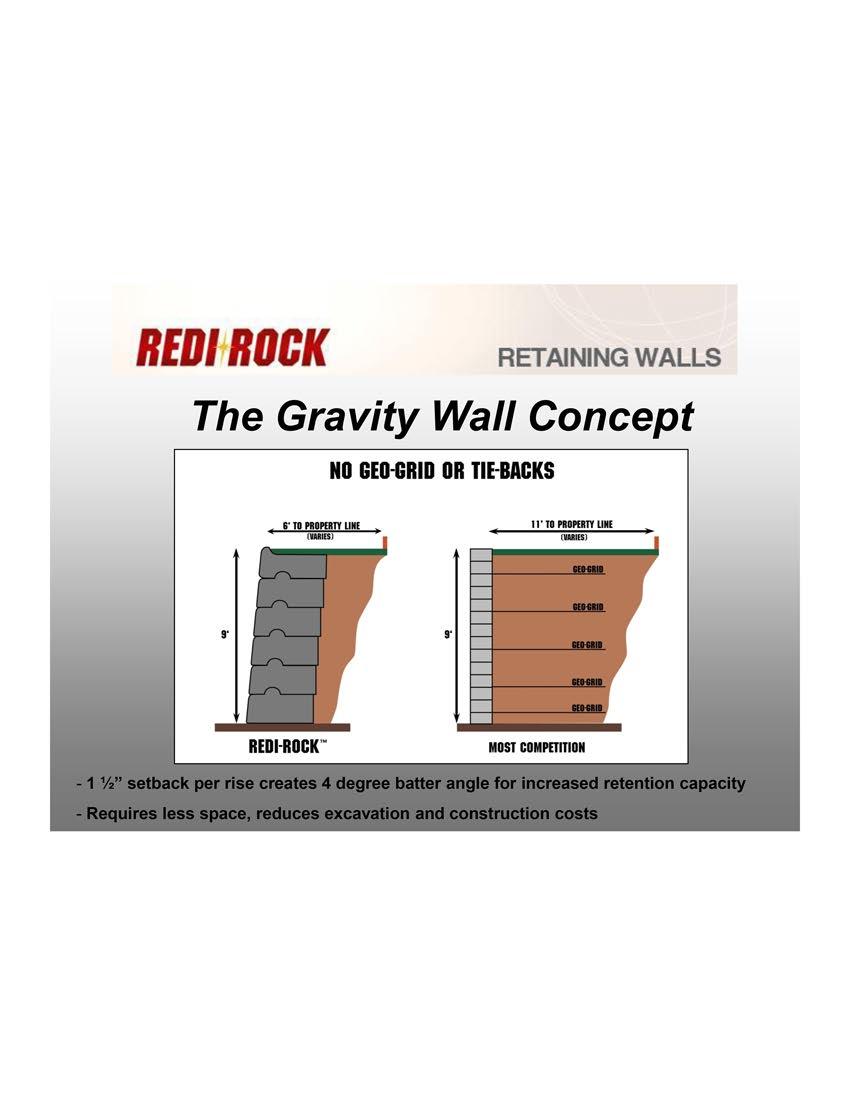
21 Preliminary Engineering Study Volume I: Preliminary Report Richland Avenue Pedestrian Crossing Analysis City of Athens, Ohio City of Athens Storm The preliminary design accounts for redesigned drainage of the Richland Avenue corridor within the project area, as well as drainage for the proposed pedestrian tunnel (see Figure 2-5). Curb inlets would be placed at the northern end of the project at the grade break to catch all water flowing from the pavement above the proposed tunnel to Bobcat Lane. These curb inlets would drain to the south via 130 of proposed 12 storm line to an existing curb inlet that will need to be reconstructed to grade. The existing storm line continues south and ties into a manhole in the existing bus stop, that will be need to be reconstructed to grade. Two 12 long 6 trench drains would be placed on the eastern and western edges of the pedestrian tunnel to catch any water at these low points of the project. The two trench drains would have 6 outlets that flow south 160 and 140 to existing structures. 3.4 Retaining Wall Structure Large Block Gravity Retaining Wall A large block gravity retaining wall, similar to those designed by Redi-Rock, was selected as the most feasible option for the retaining wall structure. These systems implement large, interlocking, precast reinforced concrete blocks without the need for geogrid tiebacks (see Figure 3-3). This is particularly useful in retaining wall structures for roadway corridors, as utilities within the roadway may need to be excavated and replaced in the future. This excavation would render the structural integrity of geogrid tiebacks for a segmental retaining wall compromised if the tieback were to be damaged. A Large Block Gravity Retaining Wall system would require shorter road closure times than a conventional reinforced concrete retaining wall because of its preformed and prefit nature. Redi-Rock s systems can implement a range of 2,400 lb to 3,500 lb blocks with shear knobs to construct the gravity stabilized wall. Redi-Rock offers three face textures and a variety of colors to add aesthetic quality to the wall (see Figure 3-4). The Cobblestone and Limestone textured blocks are manufactured in a natural finish, but can be stained and sealed onsite if the project requires. The Ledgestone textured blocks may be manufactured with color. A similar retaining wall structure was implemented on Mulberry Street just northeast of this project as shown in Figure 3-5. The proposed retaining wall would be 10 tall at its highest point adjacent to the proposed pedestrian tunnel. The Buckley Group, LLC January 12, 2016 Page 14
22


23 BLOCK LIBRARY Three Custom Textures, One Complete System Redi-Rock is a complete retaining wall solution that looks good. Engineers love it because it combines solid engineering and aesthetics, which can be a hard combination to find. Redi-Rock offers three face textures: Ledgestone, Cobblestone, and Limestone. Any block in the Redi-Rock arsenal can be produced in any texture, which means that you can create a complete solution for your next project. Retaining wall blocks, freestanding blocks, and columns are available in each of the three textures, allowing you to design an integrated, coordinated project that looks awesome. Because Redi-Rock is made from first-use, architectural grade precast concrete, the detail in texture and the durability are phenomenal. Each Redi-Rock block is cast in one continuous pour using molds taken from actual stone. These molds are bolt-on attachments to the Redi-Rock steel forms which can be interchanged from form to form. This means that a Redi-Rock manufacturer can use a single form to make a Ledgestone gravity block one day and a Limestone PC block the next day by simply switching out a few parts and pieces! This comprehensive forming system allows your local Redi-Rock manufacturer to create a variety of blocks, resulting in a faster, more affordable finished product. Ledgestone Cobblestone Redi-Rock blocks are also available in a variety of color options to match the natural stone in your local area. Contact your local Redi-Rock manufacturer for color options! Limestone 30 Design Resource Manual v Redi-Rock International, LLC


24 Preliminary Engineering Study Volume I: Preliminary Report Richland Avenue Pedestrian Crossing Analysis City of Athens, Ohio Figure 3-5: Mulberry Street Retaining Wall Figure 3-6: Redi-Rock Retaining Wall with Culvert The Buckley Group, LLC January 12, 2016 Page 17


25 Preliminary Engineering Study Volume I: Preliminary Report Richland Avenue Pedestrian Crossing Analysis City of Athens, Ohio Figure 3-7: Redi-Rock Retaining Wall with Pedestrian Tunnel Figure 3-8: Curved Redi-Rock Retaining Wall The Buckley Group, LLC January 12, 2016 Page 18

26 Preliminary Engineering Study Volume I: Preliminary Report Richland Avenue Pedestrian Crossing Analysis City of Athens, Ohio 3.5 Concrete Parapet Railing The proposed roadway corridor would require a crash barrier for vehicular traffic. The existing concrete parapet railing design on the Oxbow Bridge (see Figure 3-9) is proposed to be used to add continuity to the Richland Avenue corridor. Many historical railroad bridges within Athens County have a similar design. The railroad history of Athens County was especially important for the construction of the Oxbow Bridge, as artistic railroad murals were cast into the abutment walls. The Oxbow Bridge parapet railing also utilizes concrete with exposed aggregate. This finish of concrete is also used in various areas surrounding the Richland Avenue corridor. Implementing the existing concrete railing design in the Richland Avenue Pedestrian Crossing project would bring historical aesthetics and significance to the new construction. Figure 3-9: Oxbow Bridge Parapet Railing The Buckley Group, LLC January 12, 2016 Page 19

27 Preliminary Engineering Study Volume I: Preliminary Report Richland Avenue Pedestrian Crossing Analysis City of Athens, Ohio 3.6 Incidentals Lighting is necessary for the proposed pedestrian tunnel to discourage crime and vandalism. Costs for approach lighting to the tunnel and lighting through the tunnel are included in the project. See Figure 3-10 for an example of artistic tunnel lighting that may be implemented in this project. Roadway lighting is currently being explored in the Richland Avenue Lighting and Sidewalk project. Figure 3-10: Tunnel Lighting Example The Buckley Group, LLC January 12, 2016 Page 20
 is proposed to be removed for this project. The proposed roadway grade does not allow for the bus stop to stay in its current location.")
28 Preliminary Engineering Study Volume I: Preliminary Report Richland Avenue Pedestrian Crossing Analysis City of Athens, Ohio The bus stop on east side of Richland Avenue at West Green Drive (see Figure 3-11) is proposed to be removed for this project. The proposed roadway grade does not allow for the bus stop to stay in its current location. Cost for relocation is not included in this report, but the bus stop could easily be moved south of West Green Drive. Figure 3-11: Richland Avenue Bus Stop 3.7 Cost Estimates See Table 3-1 for the cost estimate for the proposed Richland Avenue Pedestrian Tunnel project. See Table 3-2 for the cost estimate for the Richland Avenue Lighting and Sidewalk project. The Buckley Group, LLC January 12, 2016 Page 21
29 ENGINEER'S OPINION OF PROBABLE PROJECT COST The Buckley Group 499 Richland Avenue Athens, OH Telephone: (740) Fax: (740) PROJECT: LOCATION: Richland Avenue Pedestrian Tunnel DATE 12/15/2015 City of Athens PROJECT NO BASIS FOR ESTIMATE: [X] CONCEPTUAL [] PRELIMINARY [] FINAL PREPARER CDK WORK: This project consists of the construction of a grade separation and pedestrian tunnel on Richland Avenue. CHECKED BY ENR RDB RDB Option #1 - Tunnel 3' below existing Grade ITEM DESCRIPTION QTY. UNIT UNIT COST TOTAL COST BASE BID ROADWAY 202 Pavement Removed 1389 SY $6.50 $9, Walk Removed 3401 SF $1.50 $5, Curb & Gutter Removed 874 FT $4.50 $3, Catch Basin Removed 2 EA $ $ Pipe Removed, Under 24" 197 FT $12.00 $2, Excavation 159 CY $18.50 $2, Embankment 3129 CY $22.00 $68, Subgrade Compaction 1310 SY $3.00 $3, " Concrete Walk 4906 SF $6.50 $31, Concrete Steps, Type B 32 FT $ $8, Steel Railings Luminaire Support Removed FT EA $ $ $45, $3, Luminaire Removed 6 EA $ $ SUB-TOTAL ROADWAY $185, STRUCTURE Concrete, Misc., Precast Railing and Posts Cellular Retaining Wall CY SF $2, $48.00 $93, $156, Precast Reinforced Concrete Arch Sections 36 FT $1, $66, Misc. Retaining Wall 12 CY $ $9, Granular Embankment, Type B 1204 CY $68.00 $81, SUB-TOTAL STRUCTURE $407, UTILITY RELOCATION Ohio University Tunnel Reconstruct 50 FT $3, $175, Ohio University Utilities in Tunnel 1 LUMP $75, $75, Fiber Optic Manhole Reconstructed to Grade 1 EA $4, $4, Gas Line Relocated 140 FT $ $35, SUB-TOTAL UTILITIES $289, EROSION CONTROL 659 Topsoil 150 CY $32.00 $4, Seeding and Mulching 1250 SY $4.00 $5, Erosion Control 6500 LUMP $1.00 $6, SUB-TOTAL EROSION CONTROL $16,300.00
30 ENGINEER'S OPINION OF PROBABLE PROJECT COST The Buckley Group 499 Richland Avenue Athens, OH Telephone: (740) Fax: (740) PROJECT: LOCATION: Richland Avenue Pedestrian Tunnel DATE 12/15/2015 City of Athens PROJECT NO BASIS FOR ESTIMATE: [X] CONCEPTUAL [] PRELIMINARY [] FINAL PREPARER CDK WORK: This project consists of the construction of a grade separation and pedestrian tunnel on Richland Avenue. CHECKED BY ENR RDB RDB Option #1 - Tunnel 3' below existing Grade ITEM DESCRIPTION QTY. UNIT UNIT COST TOTAL COST BASE BID DRAINAGE 605 6" Shallow Pipe Underdrains 660 FT $9.00 $5, Manhole, Reconstructed to Grade 1 EA $1, $1, Catch Basin, No. 3A 2 EA $1, $3, " Conduit, Type B 166 FT $59.00 $9, " Conduit, Type B 300 FT $52.00 $15, Trench Drain SUB-TOTAL DRAINAGE PAVEMENT 24 FT $ $4, Asphalt Concrete Base, PG CY $ Aggregate Base 218 CY $72.00 $40, $40, $15, Asphalt Concrete Surface Course, Type 2 (448), PG CY $ $14, Asphalt Concrete Surface Course, Type 1 (448), PG CY $ $16, Combination Curb and Gutter, Type 2, As Per Plan 96 FT $28.00 $2, SUB-TOTAL PAVEMENT $89, WATER WORK 638 8" Gate Valve and Heavy Duty Valve Box 2 EA $1, $3, " Ductile Iron Water Pipe, Class FT $ $33, SUB-TOTAL WATER WORK $37, LIGHTING 625 Light Pole, Decorative, As Per Plan 6 EA $2, $15, Light Pole Foundation, 24" x 6' Deep 6 EA $1, $8, No. 4 AWG 600 Volt Distribution Cable 325 FT $3.25 $1, Conduit, 2", FT $7.50 $2, Luminaire, Decorative, As Per Plan 6 EA $2, $16, Trench, 24" Deep 325 FT $7.50 $2, Ground Rod 6 EA $ $1, Light Pole Removed 5 EA $ $ Light Pole Foundation Removed 5 EA $ $ Lighting, Misc.: Pedestrian Tunnel Lighting 1 LUMP $50, $50, SUB-TOTAL LIGHTING $98,706.25
31 ENGINEER'S OPINION OF PROBABLE PROJECT COST The Buckley Group 499 Richland Avenue Athens, OH Telephone: (740) Fax: (740) PROJECT: LOCATION: Richland Avenue Pedestrian Tunnel DATE 12/15/2015 City of Athens PROJECT NO BASIS FOR ESTIMATE: [X] CONCEPTUAL [] PRELIMINARY [] FINAL PREPARER WORK: This project consists of the construction of a grade separation and pedestrian tunnel on Richland Avenue. CHECKED BY ITEM DESCRIPTION QTY. UNIT UNIT COST TOTAL COST BASE BID Option #1 - Tunnel 3' below existing Grade Centerline 0.07 MILE $9, Lane Arrow (Bike Lane) 8 EA $ TRAFFIC CONTROL Removal of Ground Mounted Post and Disposal 4 EA $ SUB-TOTAL TRAFFIC CONTROL LANDSCAPING 661 Deciduous Tree, 3" Caliper 10 EA $ Planting Bed, Misc. 1 LUMP $35, $35, ENR CDK RDB RDB $ Edge Line, 4" 0.14 MILE $6, $ $1, Bike Lane Symbol Marking 8 EA $ $2, Sign, Flat Sheet 25 SF $25.00 $ Removal of Pavement Marking 168 FT $12.00 $2, Ground Mounted Support, No FT $10.00 $1, Removal of Ground Mounted Sign and Disposal 6 EA $ $ INCIDENTALS 614 Maintaining Traffic LUMP $ $10, $7, $42, $65, Construction Layout Stakes LUMP $12, Mobilization LUMP $50, SUB-TOTAL INCIDENTALS $127, CONSTRUCTION COST $1,344, % CONTINGENCY $134, ESTIMATED TOTAL TOTAL CONSTRUCTION COST $1,479,012.43
32 ENGINEER'S OPINION OF PROBABLE PROJECT COST The Buckley Group 499 Richland Avenue Athens, OH Telephone: (740) Fax: (740) PROJECT: LOCATION: Richland Lighting & Sidewalk Ext. DATE 12/28/2015 City of Athens PROJECT NO BASIS FOR ESTIMATE: [ ] CONCEPTUAL [X] PRELIMINARY [] FINAL PREPARER RDB WORK: This project consists of Lighting and Sidewalk replacement on Richland Ave. CHECKED BY RDB ENR NA ITEM DESCRIPTION QTY. UNIT UNIT COST TOTAL COST BASE BID ROADWAY 202 Removal of Curb 1380 LF $6.75 $9, Removal of Sidewalk SF $3.75 $49, " Concrete Walk SF $9.75 $127, Removal of Pole Mounted Sign and Reerection 7 EA $ $1, $187, ELECTRICAL 625 Connection, Fused Pull Apart 42 EA $72.00 $3, Connection, Unfused Permenant 6 EA $81.50 $ Light Pole, Decorative, As Per Plan 21 EA $3, $67, Light Pole Foundation, 24" x 6' Deep, As Per Plan 21 EA $ $20, No. 4 AWG 600 Volt Distribution Cable 8487 FT $2.30 $19, No. 10 AWG Pole and Bracket Cable 630 FT $1.25 $ Conduit, 2", FT $2.50 $5, Conduit, Concrete Encased, As Per Plan (3") 308 FT $24.50 $7, Conduit, Concrete Encased, As Per Plan (4") 308 FT $27.50 $8, Luminaire, Post Top, Solid State (LED), As Per Plan 21 EA $1, $35, Trench, As Per Plan 2658 FT $4.90 $13, Pull Box, , 18" 8 EA $ $5, Ground Rod 21 EA $ $3, Plastic Caution Tape 2658 FT $0.50 $1, Light Pole Removed 8 EA $ $1, Light Pole Foundation Removed 8 EA $ $1, Distribution Cable Removed 1200 FT $0.60 $ $195, INCIDENTALS Maintaining Traffic LUMP $16, Construction Layout Stakes LUMP $1, Mobilization LUMP $5, $23, SUB-TOTAL BASE BID $406,047.30

![15629 BASIS FOR ESTIMATE: [ ] CONCEPTUAL [X] PRELIMINARY [] FINAL PREPARER RDB WORK: This project consists of Lighting and Sidewalk replacement on Richland Ave.](/docs-images/75/72799746/images/33-3.jpg "CHECKED BY ENR RDB NA ITEM DESCRIPTION QTY. UNIT UNIT COST TOTAL COST BASE BID AlTERNATE 1 Convo Asphalt Sidewalk ROADWAY 202 Pavement Removed, Asphalt Sidewalk 1205 SY $5.50 $6,627.")
33 ENGINEER'S OPINION OF PROBABLE PROJECT COST The Buckley Group 499 Richland Avenue Athens, OH Telephone: (740) Fax: (740) PROJECT: Richland Lighting & Sidewalk Ext. DATE 12/28/2015 LOCATION: City of Athens PROJECT NO BASIS FOR ESTIMATE: [ ] CONCEPTUAL [X] PRELIMINARY [] FINAL PREPARER RDB WORK: This project consists of Lighting and Sidewalk replacement on Richland Ave. CHECKED BY ENR RDB NA ITEM DESCRIPTION QTY. UNIT UNIT COST TOTAL COST BASE BID AlTERNATE 1 Convo Asphalt Sidewalk ROADWAY 202 Pavement Removed, Asphalt Sidewalk 1205 SY $5.50 $6, Asphalt Concrete Intermediate Course, Type CY $ $55, Asphalt Concrete Surface Course, Type CY $ $28, $90, SUB-TOTAL ALTERNATE 1 CONVO ASPHALT SIDEWALK ESTIMATED TOTAL CONSTRUCTION COST 10% CONTINGENCY ESTIMATED TOTAL PROJECT COST $90, $496, $49, $545,847.28
34 Preliminary Engineering Study Volume I: Preliminary Report Richland Avenue Pedestrian Crossing Analysis City of Athens, Ohio 4.0 DESIGN ALTERNATES This section outlines various alternates to the focus of design highlighted in the previous section, as well as advantages and disadvantages. 4.1 Alternative Grade Separation Elevations One of multiple alternative grade separation elevations could be selected. The pedestrian crossing 3 below existing grade was selected because it allows for an easily navigable and somewhat continuous roadway running grade above the crossing, ADA accessibility, and less utility conflict. Installing a pedestrian tunnel at existing grade (see Figure 4-1) would increase the roadway grade from West Green Drive to the tunnel top to approximately 7.5% with a -2.9% grade back down to Bobcat Lane. This would substantially disjoint the Richland Avenue corridor, as the Oxbow Bridge runs at approximately 6%. The significant negative grade, only to break and go back uphill after Bobcat Lane, made this alternative less desirable than the one selected for the Focus of Design. An advantage to an at-grade pedestrian tunnel is that the existing sidewalk approaches to the crossing would remain relatively unchanged, and there would not be utility conflicts requiring relocation. Utilities would primarily only need access points such as manholes and valves to be adjusted to grade. The storm sewer system would be required to be redesigned as outlined in section Installing a pedestrian tunnel 5 below existing grade (see Figure 4-1) would decrease the grade from West Green Drive to the tunnel top to approximately 4.3% from the 5.78% as described in the Focus of Design. The grade to Bobcat Lane would be practically zero. This would still create two tiers along Richland Avenue, but the running grade of the roadway in the project area would be slightly less noticeable. Lowering the pedestrian tunnel to 5 below existing grade would make ADA accessibility a significantly larger challenge. Maintaining a 5% maximum running grade for the ADA serpentine route on the west side of Richland Avenue would require approximately 213 feet of ramp as opposed to the 173 feet of ramp required for the Focus of Design. The pedestrian route on the east side of Richland Avenue from Porter Hall would require a serpentine route at the maximum 8.33% to meet the tunnel floor. Designing this route would be a considerable challenge due to the close proximity of Porter Hall and Grover Center, as well as a mature tree obstruction. Lowering the tunnel to 5 below existing grade would also present significant utility conflicts. As with the Focus of Design option, a section of the Ohio University utility tunnel would need to be reconstructed, the 12 steel Columbia Gas line would need to be relocated, as well as the 8 City of Athens waterline. The Frontier Communications existing conduits would need to be relocated, imparting a potential prohibitive cost on the project. Substantial excavation would be required to install the tunnel 5 below existing grade. The Buckley Group, LLC January 12, 2016 Page 27


35
36 Preliminary Engineering Study Volume I: Preliminary Report Richland Avenue Pedestrian Crossing Analysis City of Athens, Ohio 4.2 Alternative Wall Structures Several alternative wall structures exist for the grade separation retaining wall Segmental Retaining Wall with Geogrid A segmental retaining wall with geogrid may be used as an alternative wall structure. These walls are sometimes referred to as Mechanically Stabilized Earth Walls (MSE Walls). The wall structure is created by stacking blocks creating the wall phase and placing geogrid tiebacks in lifts underneath the wall backfill. The geogrid tiebacks hold the wall in place. Segmental retaining walls with geogrid tieback systems are available from manufacturers such as Redi-Rock or Allan Block. If a similar system were to be implemented for the Richland Avenue Pedestrian Crossing project, the wall would require tiebacks of approximately 10 feet. If utility work within the area of the tiebacks were necessary, excavation would damage or remove the structural integrity of the walls. This is of concern for the Richland Avenue corridor, as multiple utilities are present. Utility conflict with geogrid tiebacks is the main concern as to why segmental retaining walls with geogrid were not selected as the Focus of Design Reinforced Concrete Retaining Wall with Brick Face A reinforced concrete retaining wall with a brick face may also be selected as an alternative wall structure. A reinforced concrete retaining wall would not pose the utility conflict that a segmental retaining wall with geogrid tiebacks would. A brick faced wall would blend well within the City of Athens landscape. Much of Uptown Athens is paved in brick, and there are many brick faced buildings. The estimated additional cost of constructing a reinforced concrete retaining wall with brick face for the Focus of Design is $128,000 as shown in Table 4-1. The Buckley Group, LLC January 12, 2016 Page 29
37 ENGINEER'S OPINION OF PROBABLE PROJECT COST The Buckley Group 499 Richland Avenue Athens, OH Telephone: (740) Fax: (740) PROJECT: LOCATION: Richland Avenue Pedestrian Tunnel DATE 12/15/2015 City of Athens PROJECT NO BASIS FOR ESTIMATE: [X] CONCEPTUAL [] PRELIMINARY [] FINAL PREPARER CDK WORK: This project consists of the construction of a grade separation and pedestrian tunnel on Richland Avenue. CHECKED BY ENR RDB RDB Option #2 - Tunnel 3' below existing Grade (Brick Face) ITEM DESCRIPTION QTY. UNIT UNIT COST TOTAL COST 511 Class C Concrete, Substructure 330 CY $ $173, BASE BID ROADWAY 202 Pavement Removed 1389 SY $6.50 $9, Walk Removed 3401 SF $1.50 $5, Curb & Gutter Removed 874 FT $4.50 $3, Catch Basin Removed 2 EA $ $ Pipe Removed, Under 24" 197 FT $12.00 $2, Excavation 159 CY $18.50 $2, Embankment 4333 CY $22.00 $95, Subgrade Compaction 1310 SY $3.00 $3, " Concrete Walk 4906 SF $6.50 $31, Concrete Steps, Type B 32 FT $ $8, Steel Railings 284 FT $ $45, Luminaire Support Removed 6 EA $ $3, Luminaire Removed 6 EA $ $ STRUCTURE SUB-TOTAL ROADWAY $212, Concrete, Misc., Precast Railing and Posts 37.5 CY $2, $93, Class C Concrete, Retaining Wall 90 CY $ $76, Brick Face 3250 SF $28.00 $91, Precast Reinforced Concrete Arch Sections 36 FT $1, $66, Misc. Retaining Wall 12 CY $ $9, SUB-TOTAL STRUCTURE $510, UTILITY RELOCATION Ohio University Tunnel Reconstruct 50 FT $3, $175, Ohio University Utilities in Tunnel 1 LUMP $75, $75, Fiber Optic Manhole Reconstructed to Grade 1 EA $4, $4, Gas Line Relocated 140 FT $ $35, SUB-TOTAL UTILITIES $289, EROSION CONTROL 659 Topsoil 150 CY $32.00 $4, Seeding and Mulching 1250 SY $4.00 $5, Erosion Control 6500 LUMP $1.00 $6, SUB-TOTAL EROSION CONTROL $16,300.00
38 ENGINEER'S OPINION OF PROBABLE PROJECT COST The Buckley Group 499 Richland Avenue Athens, OH Telephone: (740) Fax: (740) PROJECT: LOCATION: Richland Avenue Pedestrian Tunnel DATE 12/15/2015 City of Athens PROJECT NO BASIS FOR ESTIMATE: [X] CONCEPTUAL [] PRELIMINARY [] FINAL PREPARER CDK WORK: This project consists of the construction of a grade separation and pedestrian tunnel on Richland Avenue. CHECKED BY ENR RDB RDB Option #2 - Tunnel 3' below existing Grade (Brick Face) ITEM DESCRIPTION QTY. UNIT UNIT COST TOTAL COST BASE BID DRAINAGE 605 6" Shallow Pipe Underdrains 660 FT $9.00 $5, Manhole, Reconstructed to Grade 1 EA $1, $1, Catch Basin, No. 3A 2 EA $1, $3, " Conduit, Type B 166 FT $59.00 $9, " Conduit, Type B 300 FT $52.00 $15, Trench Drain 24 FT $ $4, PAVEMENT SUB-TOTAL DRAINAGE $40, Asphalt Concrete Base, PG CY $ $40, Aggregate Base 218 CY $72.00 $15, Asphalt Concrete Surface Course, Type 2 (448), PG CY $ $14, Asphalt Concrete Surface Course, Type 1 (448), PG CY $ $16, Combination Curb and Gutter, Type 2, As Per Plan 96 FT $28.00 $2, SUB-TOTAL PAVEMENT $89, WATER WORK 638 8" Gate Valve and Heavy Duty Valve Box 2 EA $1, $3, " Ductile Iron Water Pipe, Class FT $ $33, SUB-TOTAL WATER WORK $37, LIGHTING 625 Light Pole, Decorative, As Per Plan 6 EA $2, $15, Light Pole Foundation, 24" x 6' Deep 6 EA $1, $8, No. 4 AWG 600 Volt Distribution Cable 325 FT $3.25 $1, Conduit, 2", FT $7.50 $2, Luminaire, Decorative, As Per Plan 6 EA $2, $16, Trench, 24" Deep 325 FT $7.50 $2, Ground Rod 6 EA $ $1, Light Pole Removed 5 EA $ $ Light Pole Foundation Removed 5 EA $ $ Lighting, Misc.: Pedestrian Tunnel Lighting 1 LUMP $50, $50, SUB-TOTAL LIGHTING $98,706.25
39 ENGINEER'S OPINION OF PROBABLE PROJECT COST The Buckley Group 499 Richland Avenue Athens, OH Telephone: (740) Fax: (740) PROJECT: LOCATION: Richland Avenue Pedestrian Tunnel DATE 12/15/2015 City of Athens PROJECT NO BASIS FOR ESTIMATE: [X] CONCEPTUAL [] PRELIMINARY [] FINAL PREPARER CDK WORK: This project consists of the construction of a grade separation and pedestrian tunnel on Richland Avenue. CHECKED BY ENR RDB RDB Option #2 - Tunnel 3' below existing Grade (Brick Face) ITEM DESCRIPTION QTY. UNIT UNIT COST TOTAL COST BASE BID TRAFFIC CONTROL 644 Centerline 0.07 MILE $9, $ Edge Line, 4" 0.14 MILE $6, $ Lane Arrow (Bike Lane) 8 EA $ $1, Bike Lane Symbol Marking 8 EA $ $2, Sign, Flat Sheet 25 SF $25.00 $ Removal of Pavement Marking 168 FT $12.00 $2, Ground Mounted Support, No FT $10.00 $1, Removal of Ground Mounted Sign and Disposal 6 EA $ $ Removal of Ground Mounted Post and Disposal 4 EA $ $ SUB-TOTAL TRAFFIC CONTROL $10, LANDSCAPING 661 Deciduous Tree, 3" Caliper 10 EA $ $7, Planting Bed, Misc. 1 LUMP $35, $35, INCIDENTALS $42, Maintaining Traffic LUMP $65, Construction Layout Stakes LUMP $12, Mobilization LUMP $50, SUB-TOTAL INCIDENTALS $127, CONSTRUCTION COST $1,473, % CONTINGENCY $147, ESTIMATED TOTAL TOTAL CONSTRUCTION COST $1,621,315.03
40 Preliminary Engineering Study Volume I: Preliminary Report Richland Avenue Pedestrian Crossing Analysis City of Athens, Ohio 4.3 Bridge Grade Separation Alternative Another grade separation alternative for a pedestrian crossing is a bridge. A pedestrian bridge crossing would not require changes to current roadway grades or utility locations. ADA accessibility would be the largest challenge for a pedestrian bridge as approach sidewalks on each side of Richland Avenue would require at least 280 of 5% sloped ramp to meet the minimum 14 vertical clearance for the roadway. This would require more space than the Focus of Design alternative, and is not feasible with Porter Hall and Grover Center being within 40 of Richland Avenue. According to the Safe Routes to School Design Guide, paths that require 50% longer travel time than other available routes would most likely be ignored by pedestrians. The use of a pedestrian bridge may result in pedestrians using the at grade roadway to cross without a crosswalk, causing the same dangers and traffic congestion issues that occur now. A pedestrian tunnel, as outlined in the Focus of Design, provides visual and physical barriers in the form of the retaining walls, to prevent pedestrians from entering the roadway. 4.4 Relocation of West Green Drive or Bobcat Lane In order to decrease roadway grades, the bounding intersections of West Green Drive or Bobcat Lane may be relocated. These options would be used in conjunction with a pedestrian tunnel. West Green Drive may be altered to the south to the grass area adjacent to the existing West Green Drive southern edge of pavement. This would involve minor realignment of the West Green Drive approach to Richland Avenue. Bobcat Lane may be relocated to the grass area adjacent to the existing Bobcat Lane northern edge of pavement. Relocation of Bobcat Lane may involve reconstruction of the Ohio University utility tunnel as well. In total, approximately 1% of roadway grade could be removed from the section of Richland Avenue from West Green Drive to the proposed pedestrian tunnel outlined in the Focus of Design. The section of Richland Avenue from the proposed pedestrian tunnel to Bobcat Lane could have an increase in roadway grade to approximately 0.5% positive grade. These relocations would create a more seamless roadway grade, but were not explored further in this study due to the extra cost required and minimal impact. The Buckley Group, LLC January 12, 2016 Page 33
41 Preliminary Engineering Study Volume I: Preliminary Report Richland Avenue Pedestrian Crossing Analysis City of Athens, Ohio 5.0 CONCLUSIONS AND RECOMMENDATIONS The proposed Richland Avenue Pedestrian Crossing project would be an important project to the City of Athens and Ohio University community. Implementing a grade separation would vastly improve pedestrian safety and vehicular traffic flow along the Richland Avenue corridor. The proposed project could feasibly be completed in the summer break session of Ohio University s academic calendar to mitigate construction interruptions and challenges. Such a project would require cooperation between Ohio University and the City of Athens to meet overarching goals for both parties. A project utilities meeting was held on December 4, The possibility of lowering Frontier Communications conduits running south from MH #178 on Richland Avenue was discussed to allow for a pedestrian crossing below existing grade. As of this report, The Buckley Group has not received verification of the depth of these conduits. The cost of relocation of the conduits has not been included in the cost estimates for this project because they are located within the Right-of-Way. However, the cost of extending MH #178 to grade has been included in the cost estimates. Frontier Communications has indicated that they may request the cost of relocation of the conduits to be shared by the project. In conclusion, the most feasible design alternative is that which is outlined in section 3.0 Focus of Design. This alternative emphasizes pedestrian and driver safety, and provides pedestrian accessibility, continuous and navigable roadway grade, and minimal utility conflict. It also provides an added aesthetic appeal to the Richland Avenue corridor. This aesthetic appeal can be tailored to compliment surrounding architecture within the City of Athens and Ohio University community. The project would be required to be designed per Ohio Department of Transportation, City of Athens, and Ohio University design standards. The Buckley Group, LLC January 12, 2016 Page 34
42 Preliminary Engineering Study Volume I: Preliminary Report Richland Avenue Pedestrian Crossing Analysis City of Athens, Ohio BIBLIOGRAPHY 1. Guidance on the 2010 ADA Standards for Accessible Design, U.S. Department of Justice, Contech Engineered Solutions, < Design Resource Manual, Redi-Rock International, LLC, June 4, The Buckley Group, LLC January 12, 2016 Page 35
43 APPENDIX A: PRELIMINARY STRUCTURAL CALCULATIONS
44 The Buckley Group 499 Richland Ave Athens, OH Phone: (740) Title Richland : Tunnel Wingwalls Page : 1 Job # 15755: Dsgnr: RDB Date: 5 JAN 2016 Description... This Wall in File: z:\retainpro projects\richland tunnel.rpx RetainPro (c) , Build License : KW License To : The Buckley Group Criteria Wall height (retained height), ft Backfill slope Level Backfill angle 0.0 Embedment 1.5 Segmental Gravity Retaining Wall Code: NCMA Soil data External Soil, Phi_e 40 External soil density (In situ), pcf 130 Internal Soil, Phi_i 40 Internal soil density, pcf 130 Wall Soil Friction Angle 27 K_a(Horiz) 0.16 Stability Overturning ratio 2.01 Sliding ratio 3.01 Overturning moment, ft-lbs 15,046 Resisting moment, ft-lbs 30,309 Total lateral/sliding force, lbs 2,831 Sliding Resistance, ft 8, Total vertical force, lbs 10,150 Base length, ft 5.00 Eccentricity on base, ft 1.00 Effective base length, ft 3.51 Soil bearing pressure, psf 2, Allowable soil bearing, psf 2, Soil Bearing Ratio 1.00 Thumbnail Segmental block data Vendor selection 'Redi-Rock International' Vendor web address ' Block selection type 'Standard 60"' Block height, in Block depth, in Offset per block, in 1.25 Batter angle 3.97 Wall weight, psf Hinge height, ft Loading Dead load, psf 100 Live load, psf 250 Seismic Design Kh 0.00 Wall Analysis Table: Block Height above base Vert Lateral Shear S. F. Ft In Dec N Static Seismic Interface 9 14' 0" , ' 6" , , ' 0" , , ' 6" , ' 0" , ' 6" ,438 1, ' 0" ,525 1, ' 6" ,613 1, ' 0" ,700 2, ' 6" ,788 2, Base 0' 0" ,
45 The Buckley Group 499 Richland Ave Athens, OH Phone: (740) Title Richland : Tunnel Wingwalls Page : 2 Job # 15755: Dsgnr: RDB Date: 5 JAN 2016 Description... This Wall in File: z:\retainpro projects\richland tunnel.rpx RetainPro (c) , Build License : KW License To : The Buckley Group Segmental Gravity Retaining Wall Code: NCMA ASSUMPTIONS AND CRITERIA USED 1. References used include Design Manual for Segmental Retaining Walls, 2 nd Edition, and Segmental Retaining Walls Seismic Design Manual, 1 st Edition, both by NCMA. 2. Blocks are all same size and uniform offsets (batter) for full wall height. 3. Coulomb earth pressure theory used for earth pressures and failure plane angle. 4. Refer to geotechnical report for backfill material, compaction, and other design data and recommendations. 5. Cap blocks if used are above the retained height and neglected in this design. 6. Block sizes obtained from vendors literature and may vary with locality. 7. Average weight of block and cell infill assumed to be 120 pcf. 8. See vendor web sites (on input screen) for more information and specifications. 9. Design height is limited to 12 feet or 18 blocks, whichever is less. Contact vendor for higher designs or special conditions. 10. Seismic design is per Seismic Design Manual cited above. Also see Methodology/Seismic Design in User s Manual. 11. Vendor specifications or project specifications, whichever is more restrictive, to be followed for construction procedures. 12. Add notes and details for proper drainage. 13. See User s Manual Design Example #11 for methodology and sample verification calculations. 14. Final design responsibility is with the project Engineer-of-Record.
46 The Buckley Group 499 Richland Ave Athens, OH Phone: (740) Title Concrete : Wall Page : 1 Job # 15755: Dsgnr: Date: 5 JAN 2016 Description... This Wall in File: z:\retainpro projects\richland tunnel.rpx RetainPro (c) , Build License : KW License To : The Buckley Group Criteria Retained Height = ft Wall height above soil = 0.00 ft Slope Behind Wall = 0.00 Height of Soil over Toe 6.00 in Water height over heel = 0.0 ft = Cantilevered Retaining Wall Code: IBC 2012,ACI ,ACI Soil Data Allow Soil Bearing = 2,500.0 psf Equivalent Fluid Pressure Method Active Heel Pressure = 32.0 psf/ft = Passive Pressure = psf/ft Soil Density, Heel = pcf Soil Density, Toe = pcf Footing Soil Friction = Soil height to ignore for passive pressure = in Surcharge Loads Lateral Load Applied to Stem Adjacent Footing Load Surcharge Over Heel = 0.0 psf Lateral Load = 0.0 #/ft Adjacent Footing Load = 0.0 lbs Used To Resist Sliding & Overturning...Height to Top = 0.00 ft Footing Width = 0.00 ft Surcharge Over Toe = Height to Bottom = 0.00 ft Eccentricity = 0.00 in Used for Sliding & Overturning Load Type = Wind (W) Wall to Ftg CL Dist = 0.00 ft Axial Load Applied to Stem Footing Type Line Load (Service Level) Base Above/Below Soil Axial Dead Load = lbs Wind on Exposed Stem = 0.0 psf = 0.0 ft at Back of Wall Axial Live Load = lbs (Service Level) Poisson's Ratio = Axial Load Eccentricity = 0.0 in Design Summary Wall Stability Ratios Overturning = 3.62 OK Sliding = 1.64 OK Total Bearing Load = 12,483 lbs...resultant ecc. = 3.08 in Soil Toe = 1,624 psf OK Soil Heel = 1,150 psf OK Allowable = 2,500 psf Soil Pressure Less Than Allowable ACI Toe = 1,962 psf ACI Heel = 1,389 psf Footing Toe = 15.8 psi OK Footing Heel = 25.3 psi OK Allowable = 75.0 psi Sliding Calcs Lateral Sliding Force = 3,844.0 lbs less 100% Passive Force = less 100% Friction Force = - - 1,406.3 lbs 4,893.0 lbs Added Force Req'd =...for 1.5 Stability = 0.0 lbs OK 0.0 lbs OK Vertical component of active lateral soil pressure IS NOT considered in the calculation of soil bearing Load Factors Building Code IBC 2012,ACI Dead Load Live Load Earth, H Wind, W Seismic, E Stem Construction 2nd Stem OK Design Height Above Ftg ft = Wall Material Above "Ht" = Concrete Design Method = LRFD Thickness = 9.00 Rebar Size = # 7 Rebar Spacing = Rebar Placed at = Center Design Data fb/fb + fa/fa = Total Section Service Level lbs = Strength Level lbs = Moment...Actual Service Level ft-# = Strength Level ft-# = Moment...Allowable = 10,238.4 Shear...Actual Service Level psi = Strength Level psi = Shear...Allowable psi = 75.0 Wall Weight psf = Rebar Depth 'd' in = 4.50 Masonry Data f'm psi = Fs psi = Solid Grouting = Modular Ratio 'n' = Short Term Factor = Equiv. Solid Thick. = Masonry Block Type = Medium Weight Masonry Design Method = ASD Concrete Data f'c psi = 2,500.0 Fy psi = 60,000.0
47 The Buckley Group 499 Richland Ave Athens, OH Phone: (740) Title Concrete : Wall Page : 2 Job # 15755: Dsgnr: Date: 5 JAN 2016 Description... This Wall in File: z:\retainpro projects\richland tunnel.rpx RetainPro (c) , Build License : KW License To : The Buckley Group Footing Dimensions & Strengths Toe Width Heel Width Total Footing Width = = = 3.00 ft Footing Thickness = in Key Width = in Key Depth = in Key Distance from Toe = 3.00 ft f'c = 2,500 psi Fy = 60,000 psi Footing Concrete Density = pcf Min. As % = Top Btm.= = 3.00 in Cantilevered Retaining Wall Code: IBC 2012,ACI ,ACI Footing Design Results Factored Pressure Mu' : Upward Mu' : Downward Mu: Design Actual 1-Way Shear Allow 1-Way Shear Toe Reinforcing Heel Reinforcing Key Reinforcing Summary of Overturning & Resisting Forces & Moments Item = = = Toe 1,962 8,542 1,566 6, = = = = # in = # in = # in Heel 1,389 20,679 33,819 13, Other Acceptable Sizes & Spacings Toe: #4@ 6.17 in, #5@ 9.57 in, #6@ in, #7@ in, #8@ in, #9@ 30. Heel: #4@ 6.17 in, #5@ 9.57 in, #6@ in, #7@ in, #8@ in, #9@ 30. Key: #4@ 6.17 in, #5@ 9.57 in, #6@ in, #7@ in, #...OVERTURNING......RESISTING... Force Distance Moment Force Distance Moment lbs ft ft-# lbs ft ft-# Heel Active Pressure = 3, ,860.7 Soil Over Heel = 9, ,913.1 Surcharge over Heel = Sloped Soil Over Heel = Surcharge Over Toe = Surcharge Over Heel = Adjacent Footing Load = Adjacent Footing Load = Added Lateral Load = Axial Dead Load on Stem = Stem Above Soil = * Axial Live Load on Stem = = Soil Over Toe = Surcharge Over Toe = Total 3,844.0 O.T.M. 19,860.7 Stem Weight(s) = Stem Transitions= = = Footing Weight = 2, ,112.5 Resisting/Overturning Ratio = 3.62 Key Weight = ,265.6 Vertical Loads used for Soil Pressure = 12,482.5 lbs Vert. Component = Total = 12,232.5 lbs R.M. = 71,988.8 * Axial live load NOT included in total displayed, or used for overturning resistance, but is included for soil pressure calculation. Vertical component of active lateral soil pressure IS NOT considered in the calculation of Sliding Resistance. Vertical component of active lateral soil pressure IS NOT considered in the calculation of Overturning Resistance. Tilt Horizontal Deflection at Top of Wall due to settlement of soil (Deflection due to wall bending not considered) Soil Spring Reaction Modulus pci Horizontal Top of Wall (approximate only) in The above calculation is not valid if the heel soil bearing pressure exceeds that of the toe, because the wall would then tend to rotate into the retained soil. psf ft-# ft-# ft-# psi psi
48 The Buckley Group 499 Richland Ave Athens, OH Phone: (740) Title Concrete : Wall Page : 3 Job # 15755: Dsgnr: Date: 5 JAN 2016 Description... This Wall in File: z:\retainpro projects\richland tunnel.rpx RetainPro (c) , Build License : KW License To : The Buckley Group Rebar Lap & Embedment Lengths Information Stem Design Segment: Bottom Stem Design Height: ft above top of footing Cantilevered Retaining Wall Code: IBC 2012,ACI ,ACI Lap Splice length for #7 bar specified in this stem design segment = Development length for #7 bar specified in this stem design segment = Hooked embedment length into footing for #7 bar specified in this stem design segment = As Provided = As Required = in in in in2/ft in2/ft
49 The Buckley Group 499 Richland Ave Athens, OH Phone: (740) Title Concrete : Wall Page : 4 Job # 15755: Dsgnr: Date: 5 JAN 2016 Description... This Wall in File: z:\retainpro projects\richland tunnel.rpx RetainPro (c) , Build License : KW License To : The Buckley Group Cantilevered Retaining Wall Code: IBC 2012,ACI ,ACI
 1987-2015, Build 11.15.12.")
50 The Buckley Group 499 Richland Ave Athens, OH Phone: (740) Title Concrete : Wall Page : 5 Job # 15755: Dsgnr: Date: 5 JAN 2016 Description... This Wall in File: z:\retainpro projects\richland tunnel.rpx RetainPro (c) , Build License : KW License To : The Buckley Group Cantilevered Retaining Wall Code: IBC 2012,ACI ,ACI
51 The Buckley Group 499 Richland Ave Athens, OH Phone: (740) Title Concrete : Wall Page : 6 Job # 15755: Dsgnr: Date: 5 JAN 2016 Description... This Wall in File: z:\retainpro projects\richland tunnel.rpx RetainPro (c) , Build License : KW License To : The Buckley Group Cantilevered Retaining Wall Code: IBC 2012,ACI ,ACI Wall: Concrete Masonry ft 0.0 lbs lbs lbs Top of Soil Designer to determine bar cutoff locations lbs 1,650.0 lbs 2,310.0 lbs 2,970.0 lbs 1,320.0 lbs 1,980.0 lbs 2,640.0 lbs Applied Shear Diagram
52 The Buckley Group 499 Richland Ave Athens, OH Phone: (740) Title Concrete : Wall Page : 7 Job # 15755: Dsgnr: Date: 5 JAN 2016 Description... This Wall in File: z:\retainpro projects\richland tunnel.rpx RetainPro (c) , Build License : KW License To : The Buckley Group Cantilevered Retaining Wall Code: IBC 2012,ACI ,ACI Wall: Concrete Masonry Allowable Moment Lines: Concrete Masonry Designer to determine bar cutoff locations 0.0 ft-# 1,530.0 ft-# 3,060.0 ft-# 4,590.0 ft-# 6,120.0 ft-# 7,650.0 ft-# 9,180.0 ft-# 10,710.0 Actual ft-# = ,770.0 ft-# 12,240.0 ft-# ft Top of Soil Allow. = 10,238.4ft-# Applied Mu = Moment 0.0 Diagram MnPhi = 0.0ft-#
53 The Buckley Group 499 Richland Ave Athens, OH Phone: (740) Title Richland : Tunnel Wingwalls Page : 1 Job # 15755: Dsgnr: RDB Date: 5 JAN 2016 Description... This Wall in File: z:\retainpro projects\richland tunnel.rpx RetainPro (c) , Build License : KW License To : The Buckley Group Criteria Wall height (retained height), ft Backfill slope Level Backfill angle 0.0 Embedment 1.5 Segmental Retaining Wall with Geogrids Code: NCMA Soil data External Soil, Phi_e 40 External soil density (In situ), pcf 130 Internal Soil, Phi_i 40 Internal soil density, pcf 130 Wall Soil Friction Angle 27 K_a(Horiz) 0.16 Thumbnail Stability Overturning ratio 5.87 Sliding ratio 5.47 Overturning moment, ft-lbs 16,783 Resisting moment, ft-lbs 98,540 Total lateral/sliding force, lbs 3,081 Sliding Resistance, ft 16, Total vertical force, lbs 20,070 Base length, ft 9.40 Eccentricity on base, ft 0.63 Effective base length, ft 8.15 Soil bearing pressure, psf 2, Allowable soil bearing, psf 2, Soil Bearing Ratio Loading Dead load, psf 100 Live load, psf 250 Seismic Design Kh 0.00 Segmental block data Vendor selection Vendor web address Block selection type 'Allan Block Retaining Wall system' ' 'AB Three' Block height, in 7.62 Block depth, in Offset per block, in 0.40 Batter angle 3.00 Wall weight, psf Hinge height, ft Geogrid material Vendor Selection Vendor web address Geogrid type 'Mirafi Geogrid' ' 'Miragrid 10XT' LTDS Factor of safety 2.00 LTADS Peak connection equation N Peak connection maximum 2683 Serviceability connection equation N Wall Analysis Table: Serviceability connection maximum 1879 Block Layer Height above base Tension Connection Embed Vert S. F. Ft In Dec Static Seismic Peak Serv Le N 22 14' 0" ' 9" ' 1" ' 6" ' 10" ' 2" ' 7" ' 11" ' 3" ' 8" ' 0"
54 The Buckley Group 499 Richland Ave Athens, OH Phone: (740) Title Richland : Tunnel Wingwalls Page : 2 Job # 15755: Dsgnr: RDB Date: 5 JAN 2016 Description... This Wall in File: z:\retainpro projects\richland tunnel.rpx RetainPro (c) , Build License : KW License To : The Buckley Group Segmental Retaining Wall with Geogrids ' 5" ' 9" , ' 1" , ' 6" , ' 10" , ' 2" , ' 7" , ' 11" , ' 4" , ' 0" 0.03 Base 0' 0" ,820 Code: NCMA Summary: Resisting / Overturning Resisting Moments Item Force, lbs Distance, ft Moment, ft-lbs Wall 1, ,570 Reinf. earth 15, ,516 Sloped Dead load 841 Live load 2,103 Total 20, , ,468 98,540 Overturning Moments Item Force, lbs Distance, ft Moment, ft-lbs Earth Surcharge, DL Surcharge, LL Seismic, Wall Seismic, Reinf. Seismic, Sloped soil 2, , , , Seismic, Exterior Total 3,081 16,783 Overturning Ratio 5.87
55 The Buckley Group 499 Richland Ave Athens, OH Phone: (740) Title Richland : Tunnel Wingwalls Page : 3 Job # 15755: Dsgnr: RDB Date: 5 JAN 2016 Description... This Wall in File: z:\retainpro projects\richland tunnel.rpx RetainPro (c) , Build License : KW License To : The Buckley Group Segmental Retaining Wall with Geogrids Code: NCMA ASSUMPTIONS AND CRITERIA USED 1. References used include Design Manual for Segmental Retaining Walls, 2 nd Edition, and Segmental Retaining Walls Seismic Design Manual, 1 st Edition, both by NCMA. 2. Blocks are all same size and uniform offsets (batter) for full wall height. 3. Coulomb earth pressure theory used for earth pressures and failure plane angle. 4. Refer to geotechnical report for backfill material, compaction, and other design data and recommendations. 5. Cap blocks if used are above the retained height and are neglected in this design. 6. Geogrid LTDS and connection values for block vendors obtained from ICC Evaluation Service (ES Legacy Reports) or as provided by vendors. Since these may change or be updated, verification of values is recommended. 7. Block sizes obtained from vendors literature and may vary with locality. 8. Geogrid layers are equally spaced vertically, all same length, and laid horizontally. 9. Average weight of block and cell infill assumed to be 120 pcf. 10. See vendor web sites (on input screen) for more information and specifications. 11. Design height is limited to 16 feet or 24 blocks, whichever is less. Contact vendor for higher designs or special conditions. 12. Seismic design is per Seismic Design Manual cited above. Also see Methodology/Seismic Design in User s Manual. 13. Vendor specifications or project specifications, whichever is most restrictive, to be followed for construction procedures. 14. Add notes and details for proper drainage. 15. See User s Manual Design Example #10 for methodology and sample verification calculations. 16. Final design responsibility is with the project Engineer-of-Record.
56 APPENDIX B: REFERENCE MATERIAL


57 Meijer Corporate Pedestrian Tunnel Walker, Michigan Pedestrian Tunnel Owner: Meijer, Inc. Engineer: Prein & Newhof Contractor: Rockford Construction Technical Description: 12 Span x 11.5' Rise x 120' Length CON/SPAN B-Series Bridge System 6.5' wide x 2' thick x 120' long EXPRESS Foundations Installation: July 2015 Founded in 1934, Meijer, Inc. is credited with pioneering the modern supercenter concept. As one of the largest private companies operating nearly 200 stores in Michigan, Indiana, Ohio, Illinois, Kentucky and soon Wisconsin, it was necessary for Meijer to expand and modernize their corporate headquarters. Part of the expansion included the addition of a pedestrian tunnel under 3-Mile Road allowing Meijer employees safe passage between the company's north and south campuses. "As the largest employer in Walker, we are happy to see that they are renovating their campus and making an investment toward the future," Walker City Manager Cathy Vander Meulen said. As the best solution for the pedestrian tunnel, a 12 x 11.5 CON/SPAN B-Series Bridge System, 120' in length, was selected. During construction, it was imperative that two lanes of traffic remain open at all times on the busy, 3-Mile Road. CON/SPAN offered a quick installation, and in order to further expedite the installation, the precast bridge units were placed on 6.5' wide x 2' x 120' long precast EXPRESS Foundations. The precast structure offered a number of advantages over alternative solutions, including: the aesthetic look of the natural arch, a better water-tight joint option and the ability to use EXPRESS Foundations. The pedestrian tunnel includes lighting and electronic gates which can be closed remotely from headquarters in order to limit access at night. Fifteen precast concrete CON/SPAN arch units were installed and placed on EXPRESS Foundations. The use of all precast bridge components provided Meijer's Corporate Headquarters with an efficiently constructed bridge that saved both time and money and was constructed in less than 45 days. In addition, the structure will last and perform well for years to come. Combining the arch tunnel with precast footings from Contech Engineered Solutions allowed the contractor to install the entire tunnel quickly limiting the overall traffic impact on 3 Mile Road," stated Brandon Hildreath, Structural Engineering Manager with Prein & Newhof. "The City of Walker, Rockford Construction and Meijer Corporate were very pleased with this design Contech Engineered Solutions LLC
Franklin County Engineer's Office - Highway Design FRA-Hamilton Road Bid Tabulation
 7/07/2015 Page 1 of 20 Group: A Roadway 005 201E11000 Clearing And Grubbing 008 202E20010 Headwall Removed 10.00 EA 010 202E23000 Pavement Removed, 88.00 SQYD Concrete 012 202E23010 Pavement Removed, Asphalt
ANSWERS TO QUESTIONS RECEIVED THROUGH 1:00 PM ON MAY 24, 2018:
 ADDENDUM NO. 3 PROJECT NO. 43805 (PART A & B) PAGE 2 ANSWERS TO QUESTIONS RECEIVED THROUGH :00 PM ON MAY 24, 208: Q#32 Addendum # answered Question #7 indicating that an average depth of 3 feet for the
DESIGN RESOURCE MANUAL
 DESIGN RESOURCE MANUAL BLOCK LIBRARY Three Custom Textures, One Complete System Redi-Rock is a complete retaining wall solution that looks good. Engineers love it because it combines solid engineering
MERCED COUNTY CAMPUS PARKWAY SEGMENT 2
 MERCED COUNTY BID LIST CAMPUS PARKWAY SEGMENT 2 CONTRACT 2017191 The bidder must provide unit prices for each bid item listed below, based on the specified unit of measure. The unit price for each item
CHAPTER 12 INSTALLATION OF UTILITIES AND OTHER SYSTEMS TABLE OF CONTENTS
 CHAPTER 12 INSTALLATION OF UTILITIES AND OTHER SYSTEMS TABLE OF CONTENTS Section Title Page 12.1 General... 12-1 12.2 Design Standards... 12-1 12.2.1 General Requirements...12-1 12.2.2 Minimum Depth...12-1
SUPPLEMENTAL DRAWINGS
 CITY OF GREATER SUDBURY SUPPLEMENTAL DRAWINGS TO THE ONTARIO PROVINCIAL STANDARD DRAWINGS Rev: February 2012 CITY OF GREATER SUDBURY STANDARD DRAWINGS TABLE OF CONTENTS Greater Sudbury Standard Drawings
ADDENDUM #1 ISSUE DATE: WEDNESDAY, MARCH 16, 2016 BID DATE: TUESDAY, MARCH 22, 2016 AT 12:00 PM (NOON)
") PROJECT #: 150081 CLIENT: PROJECT TITLE: CITY OF WILMINGTON, OH AIRBORNE CONNECTOR ROAD, PHASE 1 ISSUE DATE: WEDNESDAY, MARCH 16, 2016 BID DATE: TUESDAY, MARCH 22, 2016 AT 12:00 PM (NOON) THIS IS TO CERTIFY
PROJECT #: 150081 CLIENT: PROJECT TITLE: CITY OF WILMINGTON, OH AIRBORNE CONNECTOR ROAD, PHASE 1 ISSUE DATE: WEDNESDAY, MARCH 16, 2016 BID DATE: TUESDAY, MARCH 22, 2016 AT 12:00 PM (NOON) THIS IS TO CERTIFY
DECEMBER 5, 2017 AT 2:00 P.M. (EASTERN TIME) (Estimated Cost: $5,000,000) Bids
 (Estimated Cost: $5,000,000) Bids") General Info Number: PROJECT NO. 43-17-04 : BRIDGE DECK REPAIR AND BRIDGE REMOVAL OHIO TURNPIKE OVER QUARRY ROAD, M.P. 138.0 OHIO TURNPIKE OVER INACTIVE RAILROAD, M.P. 138.2 LORAIN COUNTY, OHIO Deadline:
General Info Number: PROJECT NO. 43-17-04 : BRIDGE DECK REPAIR AND BRIDGE REMOVAL OHIO TURNPIKE OVER QUARRY ROAD, M.P. 138.0 OHIO TURNPIKE OVER INACTIVE RAILROAD, M.P. 138.2 LORAIN COUNTY, OHIO Deadline:
Welcome and thank you for spending time with us today to talk about the 75 th Street Corridor Improvement Project.
 1 Welcome and thank you for spending time with us today to talk about the 75 th Street Corridor Improvement Project. 2 During this public meeting, we will explain the 75 th Street Corridor Improvement
ENLOE CAMPUS STORM DRAIN AND STREET IMPROVEMENTS (Project Title) PROJECT NO. MAJGC / (Budget Account Number)
 PROJECT NO. MAJGC / (Budget Account Number)") EXHIBIT A CONTRACTOR'S COMPENSATION SCHEDULE FOR ENLOE CAMPUS STORM DRAIN AND STREET IMPROVEMENTS (Project Title) PROJECT NO. MAJGC / 50103-000-4150 (Budget Account Number) ITEM NO. P-S-F DESCRIPTION QTY
EXHIBIT A CONTRACTOR'S COMPENSATION SCHEDULE FOR ENLOE CAMPUS STORM DRAIN AND STREET IMPROVEMENTS (Project Title) PROJECT NO. MAJGC / 50103-000-4150 (Budget Account Number) ITEM NO. P-S-F DESCRIPTION QTY
Preliminary Engineering Report. For the. Foxglove Trail. Prepared for: The City of Moore. Prepared By:
 Preliminary Engineering Report For the Foxglove Trail Prepared for: The City of Moore Prepared By: Certificate of Authorization No. CA#5714 Expires June 30, 2016 CE Project #264 May 2016 City of Moore
Department of Building and Zoning Approaches and Sidewalks for ONE AND TWO FAMILY CONSTRUCTION
 Department of Building and Zoning Approaches and Sidewalks for ONE AND TWO FAMILY CONSTRUCTION GENERAL ITEMS SUBGRADE Prior to pouring concrete all subgrades must be wetted and compacted. All formwork
Maine Turnpike Authority
 PAVEMENT REHABILITATION & CLEAR ZONE IMPROVEMENTS MM 80.7 TO MM 88.6 202.121 Removing Existing Concrete (6CY) 1.00 LS 202.127 Removing of Existing Bituminous Pavement (470 SY) 1.00 LS 202.202 Removing
Revision 1 Dated October 2, UNIT PRICE BID SCHEDULE SCHEDULE OF PRICES FOR THE CONSTRUCTION OF THE:
 Revision 1 Dated October 2, 2014 1.3.2 UNIT PRICE BID SCHEDULE SCHEDULE OF PRICES FOR THE CONSTRUCTION OF THE: PEYTON DRIVE WIDENING - PHASE 3 AND ENGLISH CHANNEL IMPROVEMENTS Project No s. S12012 & 800360
PITTSBURGH TECHNOLOGY CENTER PUBLIC IMPROVEMENTS SITE PREPARATION CONTRACT NO. 11 BID TABULATION BID OPENING DATE: MARCH 11, 2008
 BT-1 of 7 Clearing and Grubbing L.S. $50,000.00 $50,000.00 $5,335.00 $5,335.00 $14,560.00 $14,560.00 $20,000.00 $20,000.00 $10,600.00 $10,600.00 Class 1 Excavation 4300 C.Y. $20.00 $86,000.00 $15.00 $64,500.00
Chapter 3: Permit Procedures and Requirements
 Chapter 1: General Provisions 1 1 Short Title 1 2 Jurisdiction 1 3 Amendments and Revisions 1 4 Enforcement Responsibility 1 5 Review Process 1 6 Prior Approval 1 7 Relationship to Other Standards 1 8
(D) Surface Slope Bituminous patch in front of the truncated domes must not exceed 5% measured perpendicular to the flow line or edge of roadway.
 Surface Slope Bituminous patch in front of the truncated domes must not exceed 5% measured perpendicular to the flow line or edge of roadway.") Last Revision by CO Special Provisions: 09/14/18 Page 1 S-1 (2104) REMOVE AND REPLACE BITUMINOUS PAVEMENT (ADA) Always include SP2018-143 ((2360) PLANT MIXED ASPHALT PAVEMENT (MSCR)) when using this writeup.
Last Revision by CO Special Provisions: 09/14/18 Page 1 S-1 (2104) REMOVE AND REPLACE BITUMINOUS PAVEMENT (ADA) Always include SP2018-143 ((2360) PLANT MIXED ASPHALT PAVEMENT (MSCR)) when using this writeup.
MOA Project # Golden View Drive Intersection & Safety Upgrades
 Appropriate transitions can include extending the insulation beyond the roadway improvements, reducing the insulation thickness, or angling the insulation downward. Use of a frost tolerant section, an
CITY AND COUNTY OF DENVER DEPARTMENT OF PUBLIC WORKS CONTRACT NO COLORADO CENTER BICYCLE/PEDESTRIAN BRIDGE OVER I-25
 201-00000 Clearing and Grubbing 1 LS 202-00010 Removal of Tree 1 EA 202-00035 Removal of Pipe 30 LF 202-00200 Removal of Sidewalk 431 SY 202-00203 Removal of Curb and Gutter 973 LF 202-00205 Removal of
SPECIAL PROVISIONS - SP2014 BOOK Page 1 October 8, 2013
 SPECIAL PROVISIONS - SP2014 BOOK Page 1 S-1 (2104) REMOVE AND REPLACE BITUMINOUS PAVEMENT (ADA) Always include SP2014-119 (PLANT MIXED ASPHALT PAVEMENT) or SP2014-121 (PLANT MIXED ASPHALT PAVEMENT FOR
ADDENDUM NO. 1 SR163/N 46TH ST TO N 54TH ST INTERSECTION IMPROVEMENT PROJECT REVISIONS TO CONTRACT DOCUMENTS
 General Description: Date Prepared: November 1, 2017 (253) 604-6600 KHouse@Parametrix.com Bid Number: J2017-30 ADDENDUM NO. 1 SR163/N 46TH ST TO N 54TH ST INTERSECTION IMPROVEMENT PROJECT REVISIONS TO
SECTION PAYMENT PROCEDURES
 SECTION 01 29 00 PAYMENT PROCEDURES PART 1 GENERAL 1.01 SECTION INCLUDES A. For each BID item, the WORK will be measured and paid for on either a unit price basis or on a lump sum basis. The quantities
CITY AND COUNTY OF DENVER
 2-1.1b REMOVE COMBINATION CONCRETE CURB, GUTTER AND SIDEWALK (3'-11") 2-1.2a REMOVE 6" CONCRETE CURB AND/OR GUTTER S Holly: See near STA: 25+56 S Poplar 300 LF 25 LF 2-1.4 REMOVE HANDICAP CONCRETE CURB
Section 7 Roadway GENERAL REQUIREMENTS I. TYPICAL SECTION...7-1
 Section 7 Roadway GENERAL REQUIREMENTS...7-1 I. TYPICAL SECTION...7-1 7.1 LANE WIDTHS...7-1 7.2 SHOULDER WIDTHS...7-1 7.3 CROSS SLOPE...7-2 7.4 CURB AND UNDERDRAINS...7-2 7.5 SIDEWALKS AND DRIVEWAYS...7-2
DOCUMENT ADDENDA AND MODIFICATIONS
 DOCUMENT ADDENDA AND MODIFICATIONS PART 1 1.1 PROCEDURE GENERAL A. For filing purposes, add Addenda and Modifications to the Contract Documents following this page. Modified June 20, 2017 Addenda and Modifications
SECTION GENERAL EXCAVATION
 02210-1 of 11 SECTION 02210 GENERAL EXCAVATION 02210.01 GENERAL A. Description 1. General excavation shall include but not necessarily be limited to, excavation and grading for general site work, roadways,
ADDENDUM NO. 1. for the VETERANS PARK RENOVATIONS CITY OF TALLADEGA, ALABAMA. Posting Date: June 20, 2013
 ADDENDUM NO. 1 for the VETERANS PARK RENOVATIONS CITY OF TALLADEGA, ALABAMA Posting Date: June 20, 2013 BIDDERS SHALL CONFORM TO THE FOLLOWING CHANGES AS A PART OF THE BID DOCUMENTS, WHICH SHALL BECOME
CONSTRUCTION SPECIFICATION FOR THE INSTALLATION OF ELECTRICAL CHAMBER
 ONTARIO PROVINCIAL STANDARD SPECIFICATION METRIC OPSS 602 MARCH 1993 CONSTRUCTION SPECIFICATION FOR THE INSTALLATION OF ELECTRICAL CHAMBER 602.01 SCOPE 602.02 REFERENCES 602.05 MATERIALS TABLE OF CONTENTS
SPECIAL SPECIFICATION 6664 Level (3) Communications System
 Communications System") 2004 Specifications CSJ 1200-05-014 SPECIAL SPECIFICATION 6664 Level (3) Communications System 1. Description. A. This Item will govern the installation of all facilities belonging to Level (3) Communications,
2004 Specifications CSJ 1200-05-014 SPECIAL SPECIFICATION 6664 Level (3) Communications System 1. Description. A. This Item will govern the installation of all facilities belonging to Level (3) Communications,
Highway Drainage 1- Storm Frequency and Runoff 1.1- Runoff Determination
 Highway Drainage Proper drainage is a very important consideration in design of a highway. Inadequate drainage facilities can lead to premature deterioration of the highway and the development of adverse
Project Location: Various, Anywhere, PA Bid Date: 7/16/ Rock Construction Entrance
 To: Project Name: Bidding Company Site Work Project Contact: Address: Various Phone: Fax: Bid Number: Project Location: Various, Anywhere, PA Bid Date: 7/16/2014 Clarifications: This takeoff does not include
UNIT PRICE LIST January 2009
 UNIT PRICE LIST January 2009 1 INTRODUCTION The purpose of the Unit Price List is to provide a resource for the preparation of cost estimates for subdivisions and permit projects and should be used only
1.00 LS $150, $ 150, $ 150, $ 150, $ 150, $ 150, $ 150, $ 150, $ 150, $ 150,000.
 LAS VEGAS PAVING CORP. CONTRI CONSTRUCTION COMPANY AGGREGATE INDUSTRIES-SWR, INC. TAB CONTRACTORS, INC. ITEM DESCRIPTION QTY UNIT UNIT PRICE TOTAL PRICE UNIT PRICE TOTAL PRICE UNIT PRICE TOTAL PRICE UNIT
Excavate drilled shafts in accordance with Item 416, Drilled Shaft Foundations.
 Item Excavation and Backfill for Structures 1. DESCRIPTION 2. MATERIALS Excavate for placement and construction of structures and backfill structures. Cut and restore pavement. Use materials that meet
Addendum No. 1 Issue Date: March 29, 2016
 Addendum No. 1 Issue Date: Project: Bonson and Short Street Reconstruction Contract: #1-16 Owner: City of Platteville, Wisconsin Engineer: Delta 3 Engineering, Inc. Daniel J. Dreessens, P.E. 875 South
ADDENDUM NO. 1 TO THE TENDER DOCUMENTS FOR THE CORPORATION OF THE CITY OF PENTICTON 2017-Tender Capital Works
 ADDENDUM NO. 1 TO THE TENDER DOCUMENTS FOR THE CORPORATION OF THE CITY OF PENTICTON - April 24, 2017 To All Tenderers: This Addendum is issued prior to the Tender Closing Date April 25, 2017 in accordance
YES, we received Addendum No. 1
 TRANSMITTAL SHEET Date sent: Friday, April 6, 2018 Sent to: All Planholders Deliver to: Project Estimator Transmission sent from: Reichhardt & Ebe Engineering Number of pages including this page: 36 CONFIRMATION
T a b l e o f C o n t e n t s
 C i t y o f G l a d s t o n e P u b l i c W o r k s D e s i g n S t a n d a r d s T a b l e o f C o n t e n t s SECTION THREE SANITARY SEWER REQUIREMENTS... 1 3.0000 SANITARY SEWERS... 1 3.0010 General
SPECIAL PROVISION Detours, Barricades, Warning Signs, Sequence of Work, etc.
 2004 Specifications CSJ 0299-04-049, Etc. SPECIAL PROVISION 000---979 Detours, Barricades, Warning Signs, Sequence of Work, etc. 1. Description of Project. A. General. This project provides for the construction
SPECIAL SPECIFICATION 6658 Time Warner Communications System
 2004 Specifications CSJ 1200-05-014 1. Description. SPECIAL SPECIFICATION 6658 Time Warner Communications System A. This Item will govern the installation of all facilities belonging to Time Warner Cable
SECTION CS-2. TRENCH EXCAVATION CONSTRUCTION STANDARDS
 SECTION CS-2. TRENCH EXCAVATION CONSTRUCTION STANDARDS CS-2-01. GENERAL: Trench excavation shall conform with the City Standard Specifications. In general a trench is defined as an excavation in which
ADDENDUM NO. 1 TO THE TENDER DOCUMENTS FOR THE CORPORATION OF THE CITY OF PENTICTON 2015 Capital Works 2015-Tender-02
 ADDENDUM NO. 1 TO THE TENDER DOCUMENTS FOR THE CORPORATION OF THE CITY OF PENTICTON April 23, 2015 To All Tenderers: This Addendum is issued prior to the Tender Closing Date April 30, 2015, in accordance
CITY OF ALBANY Public Works Department ADDENDUM #1 ST CROCKER LANE RECONSTRUCTION
 CITY OF ALBANY Public Works Department ADDENDUM # ST-6-02 CROCKER LANE RECONSTRUCTION In order to clarify the intent of the Specifications and Drawings, the following provisions are provided and shall
PROPOSED HIGHWAY IMPROVEMENTS FOR CONTRACT LETTING. March 9, 2018
 STATE OF OHIO DEPARTMENT OF TRANSPORTATION COLUMBUS, OHIO PROPOSED HIGHWAY IMPROVEMENTS FOR CONTRACT LETTING March 9, 2018 This pamphlet is issued solely for the purpose of circulating advance information
CUYAHOGA COUNTY, OHIO ADDENDUM NUMBER 1, APRIL 25, 2018 FOR THE CITY OF BRECKSVILLE,
 CUYAHOGA COUNTY, OHIO ADDENDUM NUMBER 1, APRIL 25, 2018 FOR THE FOR THE CUYAHOGA COUNTY DEPARTMENT OF PUBLIC WORKS RQ# 41677 BIDS DUE ON: May 1, 2018, at 2:00 p.m. ADDENDUM NUMBER 1, April 25, 2018, Page
City of St. Catharines Standard Drawings JULY Revised July 21, 2017 TES-ENG (SH)
") City of St. Catharines Standard Drawings JULY 2017 Revised July 21, 2017 TES-ENG (SH) Roads Dwg No. Revision Standard Sidewalk Detail 110-2001 1 Monolithic Curb-Faced Sidewalk for Concrete Road 110-2002
City of St. Catharines Standard Drawings JULY 2017 Revised July 21, 2017 TES-ENG (SH) Roads Dwg No. Revision Standard Sidewalk Detail 110-2001 1 Monolithic Curb-Faced Sidewalk for Concrete Road 110-2002
- DEFINITIONS (Defined Terms)
") A - DEFINITIONS (Defined Terms) A/E means Architect and Engineer. Abutting means to border upon. Access easement means an easement created for the purpose of providing vehicular or pedestrian access. ADA
A - DEFINITIONS (Defined Terms) A/E means Architect and Engineer. Abutting means to border upon. Access easement means an easement created for the purpose of providing vehicular or pedestrian access. ADA
MAINE DEPARTMENT OF TRANSPORTATION BID DATE OF OPENING : CALL ORDER : CONTRACT ID : PROJECTS STP-1277(700)S
S") MAINE DEPARTMENT OF TRANSPORTATION BID DATE OF OPENING : CALL ORDER : CONTRACT ID : 012777.00 PROJECTS ------------------------------ STP-1277(700)S COUNTY : ANDROSCOGGIN CONTRACT ID : 012777.00 MAINE
MAINE DEPARTMENT OF TRANSPORTATION BID DATE OF OPENING : CALL ORDER : CONTRACT ID : 012777.00 PROJECTS ------------------------------ STP-1277(700)S COUNTY : ANDROSCOGGIN CONTRACT ID : 012777.00 MAINE
CITY OF ELKO BID TABULATION FOR Sports Complex
 CITY OF ELKO BID TABULATION FOR Sports Complex 2017-2018 NAME Granite Construction Great Basin Engineering Contractors Road & Highway Builders CLEARING EARTHWORK 1 33701200 Mobilization @ Per Lump Sum
SECTION 6. ROAD CONSTRUCTION STANDARDS
 SECTION 6. ROAD CONSTRUCTION STANDARDS Construction of new roads or reconstruction of existing roads proposed for dedication to the County shall conform to the standards set forth in this section. Roads
Please ensure receipt of this Addendum is acknowledged on page 1 of the Form of Tender.
 No. 1 Project: 47th Ave Road Reconstruction Owner: District of Chetwynd Date: March 5, 2019 Ref. No.: 1320.0095.01 This Addendum is issued prior to Tender Closing Date, in accordance with the Tender Documents
CITY OF ROCKLIN STANDARD DRAWINGS
 CITY OF ROCKLIN STANDARD DRAWINGS November 2016 Table of Contents Page # Section 1 Section 2 Section 3 General Notes and Review Boxes 01-01 Signature Blocks... 1 01-02 General Notes (Sheet 1 of 8)... 2
CITY OF ALBANY Public Works Department ADDENDUM #1 ST , MAIN STREET REHABILITATION
 CITY OF ALBANY Public Works Department ADDENDUM #1 ST-13-04-2014, MAIN STREET REHABILITATION In order to clarify the intent of the Specifications and Drawings, the following provisions are provided and
SECTION TRENCHING
 SECTION 31 23 17 TRENCHING PART 1 GENERAL 1.1 SUMMARY A. Section Includes: 1. Excavating trenches for utilities and utility structures. 2. Bedding. 3. Backfilling and compacting to subgrade elevations.
PROJECT UPDATE SOUTH NORFOLK JORDAN BRIDGE CITIES OF PORTSMOUTH AND CHESAPEAKE, VIRGINIA. April 2012
 PROJECT UPDATE Rendering View from the City of Chesapeake Elizabeth River Boat Landing and Park looking across the Elizabeth River at Portsmouth CITIES OF PORTSMOUTH AND CHESAPEAKE, VIRGINIA The new 5,375
Maine Turnpike Authority
 Company Name Total Bid Amount CPM Constructors - Freeport, ME $1,417,760.75 Scott Construction - Falmouth, ME $1,418,884.50 T Buck Construction - Auburn, ME $1,520,203.00 Page 1 of 16 CPM Constructors
ADDENDUM NO. 1 TO THE INVITATION TO BID - ITB # RAMP & SIDEWALK REPAIR PROJECT CITY OF ANN ARBOR, MICHIGAN
 ADDENDUM NO. 1 TO THE INVITATION TO BID - ITB #4320 2014 RAMP & SIDEWALK REPAIR PROJECT CITY OF ANN ARBOR, MICHIGAN The following changes, additions, and/or deletions shall be made to the Bid Documents
Bids JANUARY 10, 2019 AT 2:00 P.M. (EASTERN) (Estimated Cost: $29,000,000.00) Miller Bros. Const., Inc. $27,699,031.59
 (Estimated Cost: $29,000,000.00) Miller Bros. Const., Inc. $27,699,031.59") General Info Number: PROJECT NO. 43-19-07 Description: BRIDGE REHABILITATION AND 3RD LANE WIDENING OHIO TURNPIKE OVER AI CREEK M.P. 47.4, OHIO TURNPIKE OVER S.R. 64 (N. MAIN ST.) M.P. 47.5 MILEPOST 46.50
General Info Number: PROJECT NO. 43-19-07 Description: BRIDGE REHABILITATION AND 3RD LANE WIDENING OHIO TURNPIKE OVER AI CREEK M.P. 47.4, OHIO TURNPIKE OVER S.R. 64 (N. MAIN ST.) M.P. 47.5 MILEPOST 46.50
SECTION SITE PREPARATION. A. PART A and DIVISION 1 of PART B are hereby made a part of this SECTION.
 SECTION 311000 PART 1 GENERAL 1.01 GENERAL REQUIREMENTS A. PART A and DIVISION 1 of PART B are hereby made a part of this SECTION. B. Examine all conditions as they exist at the project prior to submitting
Department: Corporate Services Fax: To: Distribution List From: Bernadette Lawler/Marla Sutherland
 Department: Corporate Services Fax: 705-876-4607 To: Distribution List From: Bernadette Lawler/Marla Sutherland Fax: 705-876-4607 Date: February 23, 2015 Phone: Pages: 13 including this cover page Re:
CONDITIONS EXISTING EXISTING CONDITIONS SURVEY PROVIDED BY EGAN, FIELD & NOWAK ON FEBRUARY 20, PRELIMINARY - NOT FOR CONSTRUCTION
 K:\TWC_LDEV\\ABRA\Maple Grove, \ Design\CAD\PlanSheets\C- CONDITIONS.dwg April 4, 018 - :44pm 40 0 8 CONDITIONS SURVEY PROVIDED EGAN, FIELD & NOWAK ON FEBRUARY 0, 018. LIMITS OF CONSTRUCTION OVERHEAD POWER
Applying for a Kinder Morgan Cochin Canada / UTOPIA Canada Proximity & Crossing Permit. Design and Construction Guidelines
 Applying for a Kinder Morgan Cochin Canada / UTOPIA Canada Proximity & Crossing Permit Design and Construction Guidelines A Guide to Applying for a Kinder Morgan Cochin Canada / UTOPIA Canada Proximity
Amendments to the January 2016 Design Criteria Manual & Supplementary Master Municipal Construction Documents
 General Figure 2.3.1 16 Revise Revised Figure 2.3.1: New Development Areas where Secondary Suites Apply to include two new areas (#4 and 5). Water 3.3.2 Watermains 31 Add Added wording in Section 3.3.2.3
Maine Turnpike Authority
 Company Name Total Bid Amount CPM Constructors - Freeport, ME $13,984,117.36 Reed & Reed, Inc. - Woolwich, ME $14,883,139.00 Page 1 of 11 CPM Constructors Freeport, ME 201.11 Clearing AC 2.00 10000.00
SECTION MEASUREMENT AND PAYMENT
 SECTION 01026 PART 1 GENERAL 1.1 SECTION INCLUDES A. Explanation and Definitions B. Measurement C. Payment D. Schedule of Values E. Application for Payment 1.2 EXPLANATION AND DEFINITIONS A. The following
8 PROJECT IMPLEMENTATION
 8 PROJECT IMPLEMENTATION 8.1 Opinions of Costs The construction cost estimate for Grant Road Improvement Plan, based on quantities from the 30 percent construction plans is $102,120,380 in 2008 dollars.
NOTICE. Registration Form and Notice of Needed Revisions
 CONSTRUCTION MANUAL SOUTH CAROLINA DEPARTMENT OF TRANSPORTATION May 2004 NOTICE Registration Form and Notice of Needed Revisions Complete and return this registration form to receive revisions to this
VILLAGE OF LOMBARD CONTRACT DOCUMENT NUMBER SS BID PROPOSAL
 Page 312 VILLAGE OF LOMBARD CONTRACT DOCUMENT NUMBER SS-12-01 BID PROPOSAL I/We hereby agree to furnish to the Village of Lombard all necessary materials, equipment, and labor, to complete the IL ROUTE
DESIGN STANDARDS. Division 02 Existing Conditions- Site Work. General
 DESIGN STANDARDS Division 02 Existing Conditions- Site Work General I. This Division includes: A. Demolition B. Clearing and Grubbing C. Excavation, Backfill and Compaction D. Pavement Base E. Paving and
HITT STREET UNIVERSITY PROJECT #: CP REFER TO CP PLANS FOR ELECTRICAL DUCTBANK IN HITT STREET INSTALL:
 N 1133521.33 E 1689742.43 STA: 10+53.07 INSTALL: 2-10" 90 BENDS CONNECT TO MIDDLEBUSH HALL INTERIOR PLANT PLUMBING MIDDLEBUSH HALL HW1 HWS HWR 10+00 FREDRICK APARTMENTS FINE ARTS INSTALL 422 LF 10" HWS
CITY OF FRIENDSWOOD TECHNICAL SPECIFICATIONS SECTION 00005B TABLE OF CONTENTS ***CITY OF FRIENDSWOOD TECHNICAL SPECIFICATIONS***
 00005B *** *** BOLD ITALICIZED Item is bound within this specification manual. Regular non-italicized Item is not bound within this specification manual, however item is part of the contract. Contents
SECTION 14 - RESTORATION OF SURFACES TABLE OF CONTENTS
 SECTION 14 - RESTORATION OF SURFACES TABLE OF CONTENTS Section Page SECTION 14 RESTORATION OF SURFACES... 14.1 14-1 GENERAL... 14.1 14-2 PRIVATE ROADS... 14.1 14-3 STREETS AND PARKING LOTS... 14.1 14-3.01
DIVISION 31 EARTHWORK 2006 Edition, Published January 1, 2006; Division Revision Date: January 31, 2012
 2006 Edition, Published January 1, 2006; Division Revision Date: January 31, 2012 PART FIVE DOCUMENTS FOR SITE AND INFRASTRUCTURE 31 00 00. EARTHWORK 31 10 00. SITE CLEARING.1 STRUCTURE REMOVAL: Include
SPECIAL SPECIFICATION 6666 Charter Communications System
 2004 Specifications CSJ 1200-05-014 SPECIAL SPECIFICATION 6666 Charter Communications System 1. Description. A. This Item will govern the installation of all facilities belonging to Charter Communications,
ADVERTISEMENT SET DECEMBER 2013
 Sheet List Table GREELEY CANAL #2 WCR 21 PROJECT AREA N SH-392 ADVERTISEMENT SET DECEMBER 2013 LINE DESCRIPTION PROPOSED LINE POWER / COMMUNICATIONS EXISTING LINE LINE DESCRIPTION PROPOSED LINE BOUNDARY
The Most Advanced Name in Water Management Solutions TM. The most cost-effective slotted and trench surface drain systems.
 The Most Advanced Name in Water Management Solutions TM The most cost-effective slotted and trench surface drain systems. A sensible alternative to metal and concrete Since 1987, Duraslot surface drains
City of Redding Construction Standards Index
 City of Redding Construction Standards Index A. Purpose and Reference Documents... A1 B. Modifications to the Standard Specifications for Public Works Construction (Greenbook)... B1 I. Streets Materials...
Review of Plans and Specs from a Constructability Perspective
 Review of Plans and Specs from a Constructability Perspective The Executive Regional Manager and the Project Manager, with approval of the Director of Project Management, may request the Constructability
TENDER WELLCOX ACCESS ROAD ADDENDUM 1
 TENDER 2336-2019 WELLCOX ACCESS ROAD ADDENDUM 1 This addendum shall be read in conjunction with and considered as an integral part of the Tender Contract 2336-2019. Revisions supersede the information
Addendum 1. Valve & Valve Vault Replacement. Issued June 13, 2018
 155 Corey Avenue St. Pete Beach, FL 33706-1839 www.stpetebeach.org Addendum 1 Valve & Valve Vault Replacement Issued June 13, 2018 Note that this Addendum does not change the bid due date and time as stated
Regulation 18 August 2009 NO Operations and Maintenance LEVEE ENCROACHMENT STANDARDS AND PROCEDURES
 CENWP-EC DEPARTMENT OF THE ARMY PDR 30-2-5 Portland District, Corps of Engineers (Draft) P.O. Box 2946 Portland, Oregon 97208 Regulation 8 August 2009 NO. 30-2-5 Operations and Maintenance LEVEE ENCROACHMENT
Contact the Jurisdictional Engineer for materials allowed by each jurisdiction.
 Design Manual Chapter 3 - Sanitary Sewers 3C - Facility Design 3C-1 Facility Design A. Capacity of Pipe Pipe sizes 15 inches and smaller should carry the peak flow at a depth of no more than 0.67 of the
Curb Ramps [ 4.7.3] [ 4.7.2; 4.8.2; 4.1.6(3)(a)] [ 4.3.7] ADA Accessibility Survey Instructions Curb Ramps Page 1 of 6
![Curb Ramps [ 4.7.3] [ 4.7.2; 4.8.2; 4.1.6(3)(a)] [ 4.3.7] ADA Accessibility Survey Instructions Curb Ramps Page 1 of 6](/thumbs/73/68272859.jpg "Curb Ramps [ 4.7.3] [ 4.7.2; 4.8.2; 4.1.6(3)(a)] [ 4.3.7] ADA Accessibility Survey Instructions Curb Ramps Page 1 of 6") : Curb Ramps 1 [ 4.7.3] Only measure the width of the ramp section of the curb ramp (labeled ramp to the right). The ramp section of a curb ramp is also known as the ramp run. If the curb ramp has flared
: Curb Ramps 1 [ 4.7.3] Only measure the width of the ramp section of the curb ramp (labeled ramp to the right). The ramp section of a curb ramp is also known as the ramp run. If the curb ramp has flared
Grade-Separated Trail Crossings How Do We Get Over There?
 Grade-Separated Trail Crossings How Do We Get Over There? 2008 National Trails Symposium Rory Renfro, Alta Planning + Design Scott Belonger, Loris and Associates Peter Loris, Loris and Associates PRESENTATION
MONROE STREET CONTRACT NO DATE: 12/21/17
 Section B: Proposal Page 10701.0 - TRAFFIC CONTROL - LUMP SUM 1.00 $100,000.00 $100,000.00 $48,300.00 $264,800.00 10720.0 - TRAFFIC CONTROL SIGN - PORTABLE ARROW BOARD - DAYS 510.00 $15.00 $7,650.00 $10.00
CONSTRUCTION SURVEY. Construction survey includes personnel, equipment, and supplies required for, but not limited to, the following:
 CONSTRUCTION SURVEY PART 1 - GENERAL 1.01 SECTION INCLUDES Construction survey includes personnel, equipment, and supplies required for, but not limited to, the following: A. Construction Survey: 1. Project
Project Type: Drainage and Storm Systems
 580 Dakin Avenue Box Culvert & Utility Improvements Project $944,952 Improvements to approx. 3,000 lf of existing 4'x5' concrete box culvert; clean interior, patch surface, fill joints/cracks; install
SUQUAMISH WAY NE SHOULDER AND SIDEWALK IMPROVEMENT PROJECT
 CALL FOR BIDS KITSAP COUNTY DEPARTMENT OF PUBLIC WORKS COUNTY ROAD PROJECT NO. 1589 SUQUAMISH WAY NE SHOULDER AND SIDEWALK IMPROVEMENT PROJECT BID OPENING: DATE: FEBRUARY 27, 2018 TIME: 11:00 AM Sealed
C. W. Matthews Contracting Co., Inc. (L)
") BID TABULATION Page 1 of 5 E.R. Snell Contractor, 001 Photograph Documentation 8 MO $110.00 $880.00 $250.00 $2,000.00 $97.17 $777.36 $1,250.00 $10,000.00 002 Traffic Control Project No. F-1056 1 LS $192,000.00
BID TABULATION Page 1 of 5 E.R. Snell Contractor, 001 Photograph Documentation 8 MO $110.00 $880.00 $250.00 $2,000.00 $97.17 $777.36 $1,250.00 $10,000.00 002 Traffic Control Project No. F-1056 1 LS $192,000.00
Construction Specification for General Excavation
 Engineering & Construction Services Division Standard Specifications for Road Works TS 2.10 September 2018 for General Excavation Table of Contents TS 2.10.01 SCOPE... 2 TS 2.10.02 REFERENCES... 2 TS 2.10.03
CONSTRUCTION PLAN CHECKLIST
 CONSTRUCTION PLAN CHECKLIST The design engineer is responsible for ensuring that plans submitted for city review are in accordance with this checklist. It is requested that the executed checklist be submitted
2015 Financial Assurance (Basic form) 3/17/2015 Estimate Form
 3/17/2015 Estimate Form") 2015 Financial Assurance (Basic form) 3/17/2015 Estimate Form Project Information (\aen i vake.. F;) N0.3-7114117 Project Name Section 1 - Grading and Erosion Control BMPs Quantity Units Price Earthwork
2015 Financial Assurance (Basic form) 3/17/2015 Estimate Form Project Information (\aen i vake.. F;) N0.3-7114117 Project Name Section 1 - Grading and Erosion Control BMPs Quantity Units Price Earthwork
OHIO DEPARTMENT OF TRANSPORTATION JERRY WRAY, DIRECTOR DATE : 02/14/97 PAGE : TABULATION OF BIDS
 047-1 ODOT PROJECT NUMBER : 970047 AWARDED VENDOR NUMBER : 31-0889208 CALL ORDER : 047 CONTRACT ID : CADA16278 COUNTIES : ADAMS LETTING DATE : 02/04/97 10:00 AM DISTRICT : 09 CONTRACT TIME : 10/31/97 COMPLETION
STATE UNIVERSITY CONSTRUCTION FUND
 DIRECTIVE 2-1 Issue date: September 2012 1. General SITEWORK OVERVIEW This Directive outlines the Fund s requirements for the Consultant relative to the development, design and presentation of documents
PART II. - SPECIFICATIONS AND DESIGN STANDARDS TO CITY OF HEWITT, TEXAS SUBDIVISION ORDINANCE FOR PUBLIC WORKS CONSTRUCTION [TEXT]
![PART II. - SPECIFICATIONS AND DESIGN STANDARDS TO CITY OF HEWITT, TEXAS SUBDIVISION ORDINANCE FOR PUBLIC WORKS CONSTRUCTION [TEXT]](/thumbs/80/81891816.jpg "PART II. - SPECIFICATIONS AND DESIGN STANDARDS TO CITY OF HEWITT, TEXAS SUBDIVISION ORDINANCE FOR PUBLIC WORKS CONSTRUCTION [TEXT]") PART II. - SPECIFICATIONS AND DESIGN STANDARDS TO CITY OF HEWITT, TEXAS SUBDIVISION ORDINANCE FOR PUBLIC WORKS CONSTRUCTION [TEXT] A. - General. B. - Streets. C. - Stormwater drainage system. D. - Water
PART II. - SPECIFICATIONS AND DESIGN STANDARDS TO CITY OF HEWITT, TEXAS SUBDIVISION ORDINANCE FOR PUBLIC WORKS CONSTRUCTION [TEXT] A. - General. B. - Streets. C. - Stormwater drainage system. D. - Water
CONSTRUCTION SPECIFICATION FOR INSTALLATION OF ELECTRICAL CHAMBERS
 ONTARIO PROVINCIAL STANDARD SPECIFICATION OPSS.PROV 602 NOVEMBER 2017 CONSTRUCTION SPECIFICATION FOR INSTALLATION OF ELECTRICAL CHAMBERS TABLE OF CONTENTS 602.01 SCOPE 602.02 REFERENCES 602.03 DEFINITIONS
SAN ANTONIO WATER SYSTEM C5 & C28 SEWER PROJECT PHASE 3 SAWS PROJECT NO SOLICITATION NO. CO ADDENDUM-6
 SAN ANTONIO WATER SYSTEM C5 & C28 SEWER PROJECT PHASE 3 SAWS PROJECT NO. 18-4501 SOLICITATION NO. CO-00198 ADDENDUM 6 (September 10, 2018) To Respondent of Record: This addendum, applicable to work referenced
CITY COUNCIL AGENDA Workshop Meeting: Tuesday, October 24, 2017
 1 2 CITY COUNCIL AGENDA Workshop Meeting: Tuesday, October 24, 2017 AGENDA ITEM: 2 Hear and deliberate on handrail, lighting, and walkway replacement options for Key Allegro Bridge on Bayshore Drive. SUBMITTED
SECTION 1500 REMOVALS
 SECTION 1500 REMOVALS REMOVALS PART 1 GENERAL 1.01 Section Summary A. Removal of structures, obstructions, surfacing, and miscellaneous items. 1.02 Related Sections A. Section 1800 Excavation and Embankment
SUMMARY OF PUBLIC WORK STANDARD SPECIFICATION REVISIONS 2011 ADOPTED?????
 SUMMARY OF PUBLIC WORK STANDARD SPECIFICATION REVISIONS 2011 ADOPTED????? 102.10 Minimum Rate of Wage Scale Typo. Several paragraphs were repeated. 105.5 Inspection of Work Clarified that the contractor