Memorandum. FOUNDATION ENGINEERING, INC. Professional Geotechnical Services. Date: August 13, 2012 To:
|
|
|
- Leonard Stone
- 6 years ago
- Views:
Transcription

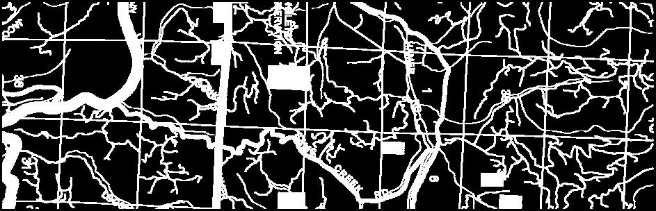
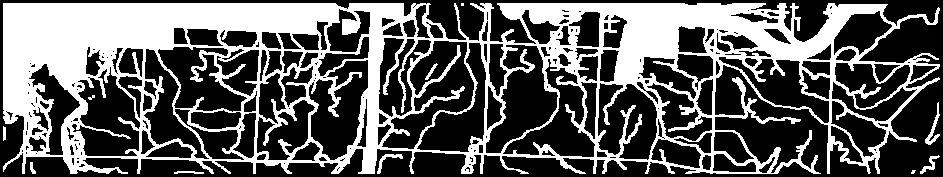
1 FOUNDATION ENGINEERING, INC. Professional Geotechnical Services Memorandum Date: August 13, 2012 To: From: Subject: Project: Brett C. Martin, P.E. LEI Engineering & Surveying, LLC James K. Maitland, P.E., G.E. Matthew D. Mason Geotechnical Investigation Miller Property Subdivision FEI Project We have completed the requested geotechnical investigation for the above-referenced project. The following summarizes our work and provides recommendations for site preparation and foundation design. BACKGROUND The Confederated Tribes of Siletz Indians of Oregon is planning a housing project in. The site is located in a field west of Siletz Hwy between W Buford Avenue and SW Swan Avenue (Figure 1A, Appendix A). The development will consist of 21 lots and associated paved access. The new structures will have framed-floors and shallow foundations. The site layout with the proposed lots and roadway is shown on Figure 2A (Appendix A). LEI Engineering & Surveying, LLC (LEI) is the civil consultant. Foundation Engineering, Inc. (FEI) was retained by LEI as the geotechnical consultant. Our scope of work was outlined in a proposal dated January 4, 2012, and authorized by a signed service agreement dated July 16, FIELD EXPLORATION We dug 12 exploratory test pits at the site on July 20, 2012, using a Kubota KX121-3, rubber-tracked excavator. The approximate test pit locations are shown on Figure 2A. Upon completion of our explorations, the test pits were backfilled with the excavated materials. The test pits extended to depths ranging from ±3 to 9 feet. Disturbed soil samples were obtained for possible laboratory testing. Undrained shear strength measurements were made on the test pit sidewalls using a Torvane shear device. The soil profile, sampling depths and strength measurements are summarized on the test pit logs (Appendix B). Ground elevations shown on the logs were estimated based on the topographic map and are approximate only. The subsurface conditions are discussed below. 820 NW Cornell Avenue Corvallis, Oregon Bus. (541) Fax (541)
2 DISCUSSION OF SITE CONDITIONS Topography and Vegetation The site is relatively flat. Topographic information provided by LEI indicates the ground elevations range from ±El. 97 at the west end of the site to ±El. 102 near the east side of the site. The vegetation within the parcel varies with location. The northwest portion of the site is primarily covered with fir trees. A ditch line vegetated with tall grass, weeds and brambles starts in the middle of the site and continues into the southwest corner of the site. A small mound of fill, located at the west side of the site, is covered with tall grass, weeds and small trees. The remaining portion of the site is primarily covered with mowed grass. Subsurface Conditions Relatively similar conditions were encountered in the test pits. profile typically includes the following soil and rock units: The subsurface Topsoil. Topsoil was encountered to ±1¾ to 3 feet. The topsoil consists of medium to high plasticity silt with some clay and organics consisting of fine roots. The roots typically extended to ±10 to 12 inches below the ground surface. The topsoil was typically damp to moist and medium stiff at the time of the field work. Clayey Silt (alluvium). The topsoil is underlain by medium to high plasticity clayey silt. The clayey silt has a blocky structure and was typically moist and stiff at the time of the exploration. This stratum extends to ±5½ to 7½ feet. Sandy SILT/silty SAND (alluvium). Brown to grey, iron-stained, medium dense to medium stiff, low to medium plasticity silty sand to sandy silt was encountered beneath the clayey silt layer within the western and southern portions of the site (TP-1 through TP-3, TP-8 and TP-12). This stratum was ±1 to 2 feet thick in TP-1, TP-3 and TP-12 and at least ±2 feet thick in TP-2 and TP-8, where it extended to the bottom of the test pits. Gravel (alluvium). Dense, fine to coarse, subrounded to rounded sandy gravel was encountered in TP-3 through TP-5, TP-9, TP-11 and TP-12. Scattered cobbles were present in the gravel in TP-4, TP-5 and TP-9. The sandy gravel was encountered beneath the clayey silt and silty sand and typically extended to the limits of the exploration (±8 to 8½ feet below the ground surface). Siltstone. Extremely weak (R0) siltstone of the Tyee Formation was encountered at a depth of ±8 feet in TP-3. Digging extended ±½-foot into the bedrock. The exposed rock surface is typically slightly to moderately weathered. Excavation below the rock surface was difficult with the Kubota KX121-3 excavator. Miller Property Subdivision August 13, 2012 Geotechnical Investigation 2. Project LEI Engineering & Surveying, LLC
3 Ground Water We observed slow ground water infiltration in several of the test pits at a depth of ±8 feet. Where ground water was observed, the depth corresponds to approximately the contact between the fine-grained and coarse-grained soils. The shallower soils were typically damp to moist at the time of the exploration. However, the observed iron-staining in the upper fine-grained soils suggests perched water conditions may develop during periods of extended rainfall and ground water levels may rise to within the ground surface during the wet winter months. Neighbors indicated standing water is often observed across the site during periods of heavy rainfall, which suggests poor infiltration characteristics of the surficial soils. Infiltration It is our understanding the project will include permeable pavements as part of the drainage design for the site. LEI requested FEI to comment on the permeability of the near-surface soils and the feasibility of the drainage plan. The site is typically underlain by ±5½ to 7½ feet of fine-grained soil over sand and gravel. The fine-grained topsoil consists of ±2 to 3 feet of medium to high plasticity silt (MH) over medium to high plasticity, alluvial clayey silt (MH). These types of soils typically have a coefficient of hydraulic conductivity (permeability), k, ranging from ±10-5 to 10-7 cm/sec. Soils with k values of less than ±10-5 cm/sec are generally considered to have very low permeability. Soils with k values less than ±10-7 cm/sec are considered to be practically impermeable. Additionally, the site s proximity to the Siletz River suggests the ground water level beneath the site will closely match the river level. During periods of extended heavy rainfall, the ground water level will likely rise to reflect rising river levels. As a result of these conditions, the subgrade beneath the proposed permeable pavements should be considered relatively impermeable and will provide little storage capacity for runoff. This is consistent with the neighbor s observations of ponding water on the site. LABORATORY TESTING Laboratory testing was limited to natural water content, percent fines and Atterberg limits tests on a sample of the foundation soil. The testing was completed to classify the soil according to the Unified Soil Classification System (USCS) and estimate its overall engineering properties. The testing indicates the foundation soils consist predominantly of medium plasticity clayey silt and silt with some clay. The test results are summarized in Table 1 and Figure 3A (Appendix A). Miller Property Subdivision August 13, 2012 Geotechnical Investigation 3. Project LEI Engineering & Surveying, LLC
4 Table 1. Atterberg Limits, Natural Water Contents, and Percent Fines Sample Number Sample Depth (feet) Moisture Content (percent) LL PL PI USCS Classification Percent Fines S S S MH S S S MH S S S S SEISMIC CONSIDERATIONS Response Spectrum A spectral acceleration response spectrum for the site was established based on Section 1613 of the Oregon Structural Specialty Code (OSSC) Based on our explorations, we anticipate the site is underlain by ±10 to 15 feet of medium stiff to stiff clayey silt, medium dense silty sand and sandy silt, and dense gravel followed by siltstone (extending to great depth). Therefore, a Site Class C is recommended for design, based on the average profile within 100 feet of the ground surface. The seismic design parameters and OSSC response spectrum are shown on Figure 4A (Appendix A). Liquefaction Liquefiable soils typically consist of saturated, loose, fine-grained sand and non-plastic silt. The liquefaction potential of the foundation soils is considered negligible due to the plasticity and stiffness of the fine-grained soils, limited thickness, density and plasticity of the silty sand and sandy silt, and the presence of shallow bedrock. Miller Property Subdivision August 13, 2012 Geotechnical Investigation 4. Project LEI Engineering & Surveying, LLC
5 ENGINEERING ANALYSIS AND DESIGN Bearing Capacity We estimated the bearing capacity of conventional (i.e., spread or continuous) footings placed on ±6 inches of compacted Select Fill underlain by silt with some clay or clayey silt. Torvane shear measurements near the anticipated foundation elevation indicated undrained shear strengths ranging from ±0.5 to 0.85 tsf. An allowable bearing capacity was calculated using conservative undrained shear strength of 0.4 tsf. These calculations suggest an allowable bearing pressure of 2,000 psf with a typical factor of safety of 3. This analysis assumes the continuous footings will have a nominal width of 18 inches and the subgrade beneath the footings would be prepared as recommended below. Settlement A conventional settlement analysis was not warranted based on the stiffness of the foundation soils and the light building loads. We recommend designing the structures to accommodate a total foundation settlement of ±½ inch. Differential settlement is also expected to be less than ±½ inch. Due to the plasticity of the subgrade, it is possible that seasonal changes in moisture could cause heave (due to wetting) or shrinkage settlement (due to drying). Therefore, provisions to reduce the potential adverse impact of differential soil movement are provided in the Recommendations section. Pavement Analysis and Design It is our understanding a pavement section for the approach aprons will be 3 inches of asphaltic concrete (AC) over 12 inches of Select Fill. The pavement section for the private street (inside the property line) will consist of a 2¾-inch thick paver block underlain by 2 inches of coarse sand and 10 inches of Select Fill over a Separation Geotextile. We conducted a pavement analysis to confirm the suitability of the proposed approach pavement section. We did not evaluate the paver pavement section. We used a computer program, assumed traffic, a subgrade modulus (Mr) of ±3,100 psi and a 20-year design life to estimate a pavement section for the new road. The assumed traffic was based on a traffic distribution of passenger vehicles and pickup trucks and light truck traffic. The subgrade modulus was determined from Dynamic Cone Penetrometer (DCP) testing completed during the field exploration. We understand only some of the housing units will be built during the initial development of the site. The rest of the housing units will be built as more funding becomes available. LEI indicated the area to be developed later is located in the northern portion where the residential road connects with W Buford Avenue. The road in this area will not be paved until after the entire site is developed. However, it should be assumed that with only 12 inches of base aggregate over a Separation Geotextile, future construction traffic will likely cause the subgrade beneath the base aggregate section to pump. Therefore, any areas where the Miller Property Subdivision August 13, 2012 Geotechnical Investigation 5. Project LEI Engineering & Surveying, LLC
6 subgrade is damaged by construction traffic should be reworked prior to paving. We recommend a FEI representative be on site to observe a proof roll of the unpaved road prior to paving. RECOMMENDATIONS The site is underlain by fine-grained alluvium. This soil will be moisture-sensitive and will soften considerably when wet. Compaction of these soils and reuse of the soil as fill will only be practical in the dry summer months when moisture-conditioning is possible. Construction during the winter will require removal of soft soils and construction of thick building pads and thick base rock sections for pavement areas to support construction traffic. Construction during wet weather will substantially increase earthwork costs relative to dry weather construction. Therefore, we recommend completing the earthwork during the dry summer months. The site is relatively flat and has poor drainage. Consequently, the surficial soils may remain wet of optimum into June. Favorable conditions for moisture-conditioning and compaction (i.e., adequately dry soils and sustained dry weather) are typically limited to July through September. The recommendations provided below assume dry weather construction and a subgrade sufficiently dry for compaction. We should be contacted to modify our recommendations if wet weather conditions are anticipated. We have also assumed, based on proposed finish grades, no significant site fill will be required. Contractors should be provided a copy of this memorandum to review recommendations for site preparation and foundation construction, and the soil and rock conditions encountered in the test pits. We should be provided an opportunity to meet with the contractor prior to construction to discuss the site conditions and the contractor s approach to site preparation. Material and Compaction Recommendations 1. Select Fill as defined in this report should consist of 1 or ¾-inch minus, clean (i.e., less than 5% passing the #200 U.S. Sieve), well-graded crushed gravel or rock. A gradation curve should be provided to us for approval, prior to delivery to the site. 2. On-Site Fill should consist of approved soil that is free of organics, construction debris or expansive clay. Unless approved by us, silts or clays should not be placed under foundation areas or under settlement-sensitive structures. Re-use of fine-grained site fill should be limited to general grading and parking lot construction. 3. Drain Rock should consist of 2-inch minus, clean (less than 2% passing the #200 sieve), open-graded gravel or rock. Miller Property Subdivision August 13, 2012 Geotechnical Investigation 6. Project LEI Engineering & Surveying, LLC
7 4. Separation Geotextile shall have Mean Average Roll Value (MARV) strength properties meeting the requirements of an AASHTO M Class 2 geotextile (geotextile for separation). The geotextile should have MARV permittivity of 0.2 to 0.5 sec. -1 and a maximum Apparent Opening Size (AOS) of 0.6 mm. We should be provided a specification sheet on the selected geotextile for approval prior to delivery to the site. 5. Filter Fabric should have Mean Average Roll Value (MARV) strength properties meeting the requirements of an AASHTO M Class 3 geotextile (subsurface drainage geotextile) with a maximum apparent opening size (AOS) of 0.3 mm and a permittivity greater than 0.1 sec Compact the subgrade (during dry weather only) and fill to 95% relative compaction. The maximum dry density of ASTM D 698 should be used as the standard for estimating the relative compaction. The moisture content of the fine-grained soil should be adjusted to within ±2% of its optimum value prior to compaction. Place and compact all fill in loose lifts not exceeding 12 inches. Thinner (±6 to 8 inch) lifts may be required if light or hand-operated equipment is used. Field density tests should be run frequently to confirm adequate compaction of the subgrade and imported fills. Granular fill that contains aggregates too coarse for density testing, or subgrade that is too variable should be proof-rolled using a loaded, 10-yd 3 dump truck or other approved vehicle. The adequacy of the compaction should be evaluated by an FEI representative. Areas of pumping or deflection observed beneath the truck wheels may be reworked, or overexcavated and replaced with compacted Select Fill and proof-rolled again. 7. Overexcavate all test pits that extend under buildings and pavements. Replace the test pit backfill with compacted Select Fill. The test pit locations identified on Figure 2A should be considered approximate only. The test pit locations were staked in the field at the time of the exploration. 8. Excavate for utilities to the required grade. Inform contractors that water infiltration may be encountered at shallow depths during the winter months, based on the observed iron-staining in the upper soils in the test pits. Trenches should be pumped dry prior to placing the backfill. Trench backfill that extends beneath the new building, pavements and hardscapes should consist of Select Fill placed and compacted as specified above. Sidewalls of trenches extending to sands and gravels can collapse suddenly, especially in the presence of seepage. Therefore, all excavations should be shored to protect workers from sloughing or caving soils according Oregon OSHA requirements for Type C soils. Miller Property Subdivision August 13, 2012 Geotechnical Investigation 7. Project LEI Engineering & Surveying, LLC
8 Site Preparation for Buildings We recommend the foundation area under the building be prepared during dry weather as follows: 9. Strip the existing ground ±4 to 6 inches or as required to remove roots and sod. Deeper stripping will be required where tree roots are encountered. Dispose of all strippings outside of construction areas. 10. Moisture-condition, compact and test the subgrade as recommended in Item 6. Compaction will not be practical if the soils are too wet of optimum. Therefore, the site work should not be attempted during wet weather and should be delayed until the subgrade soils are sufficiently dry or until weather permits efficient aeration. 11. Do not allow the subgrade to dry out following preparation. Place a minimum of 12 inches of Select Fill on the prepared subgrade to create a building pad. Place additional Select Fill as needed to raise the top of the building pad at least 12 inches above the finished grade surrounding the buildings to raise the buildings above the seasonal perched water. Compact the Select Fill as recommended in Item Grade the ground surface surrounding all buildings to promote runoff away from the foundations. 13. Provide a minimum of 6 inches of compacted Select Fill under all other isolated concrete slabs and sidewalks (dry weather construction). This rock thickness is not intended to support trucks or heavy equipment and should be increased for wet weather construction. Foundation Design and Construction We understand framed-floor construction has been selected for the project. We recommend the foundations be constructed as follows: 14. Design all continuous wall footings and isolated column footings using an allowable bearing pressure of 2,000 psf. This value assumes all footings or Select Fill underlying the footings will extend to soil having a minimum undrained shear strength of 0.4 tsf. 15. Assume total and differential settlements of ½ inch or less, if the footings are designed and built as specified herein. 16. Design the buildings assuming the seismic parameters and Site Response Spectrum provided in Figure 4A. Values provided in Figure 4A are based on the Oregon Structural Specialty Code (OSSC) 2010 (Section 1613). 17. The framed-floor should be supported on continuous reinforced interior and exterior wall footings. Miller Property Subdivision August 13, 2012 Geotechnical Investigation 8. Project LEI Engineering & Surveying, LLC
9 18. Provide a minimum footing width of 18 inches for continuous wall footings. Place the base of all footings at least 18 inches below the adjacent finished grade. 19. Trench for footings using a hoe equipped with a smooth bucket to reduce subgrade disturbance. The excavations should be deep enough to accommodate a minimum of 6 inches of compacted Select Fill beneath the footings. Excavations should terminate in silt having a minimum undrained shear strength of 0.4 tsf. All footing excavations should be evaluated by an FEI representative prior to backfilling. 20. Overexcavate any unsuitable fill or debris encountered beneath footings. Backfill the overexcavated areas using compacted Select Fill. If needed, dewater the excavations prior to placing backfill. All footing excavations should be evaluated by an FEI representative prior to backfilling. 21. Provide a suitable vapor barrier on the surface of the crawl space. 22. Garage slabs and any concrete driveways should be reinforced to reduce cracking and warping. Rebar, instead of wire mesh, is recommended due to potential seasonal soil movement. The use of fiber as the sole method of reinforcement is not recommended. Drainage for Buildings 23. Install foundation drains along the perimeter of the buildings. The drains should consist of 3 or 4-inch diameter, perforated or slotted, PVC pipe. The flowline of the pipe should be set at the footing grade. The pipe should be bedded in at least 4 inches of Drain Rock and backfilled to within 6 inches of the ground surface with Drain Rock. The entire mass of Drain Rock should be wrapped in a Filter Fabric that laps at least 12 inches at the top. 24. Provide clean-outs at appropriate locations for future maintenance of the drainage systems. 25. Discharge by gravity flow into the nearest storm drain. If necessary, discharge the water into a common sump and pump it into the nearest storm drain. Subgrade Preparation for Pavements 26. Strip the existing ground ±4 to 6 inches or as required to remove sod and roots. Additional excavation may be required where tree roots or unsuitable soils are present. Dispose of all strippings outside of construction areas. 27. Moisture-condition and compact the subgrade and any On-Site Fill as recommended in Item 6. Miller Property Subdivision August 13, 2012 Geotechnical Investigation 9. Project LEI Engineering & Surveying, LLC
10 28. Do not allow the subgrade to dry out excessively. Immediately cover the prepared subgrade with a Separation Geotextile. 29. The geotextile should be laid smooth, without wrinkles or folds in the direction of construction traffic. Overlap adjacent rolls a minimum of 2 feet. Pin fabric overlaps or place the building pad fill in a manner that will not separate the overlap during construction. Seams that have separated will require removal of the building pad fill to establish the required over lap. 30. Assume the subgrade will have relatively low permeability. DESIGN REVIEW/CONSTRUCTION OBSERVATION/TESTING We should be provided the opportunity to review all drawings and specifications that pertain to site preparation and foundation construction. Site preparation will require field confirmation of the foundation conditions and proper subgrade preparation, in particular, if the soils are wet of optimum. Therefore, we recommend we be present during site grading, foundation construction, and subgrade preparation for pavements. Mitigation of any subgrade pumping or presence of persistent ground water will also require engineering review and judgment. That judgment should be provided by one of our representatives. Field density tests should be run on all engineered fill. We recommend we be retained to provide the necessary construction observations. VARIATION OF SUBSURFACE CONDITIONS, USE OF THIS REPORT AND WARRANTY The analysis, conclusions and recommendations contained herein are based on the assumption that the soil profiles encountered in the test pits and the ground water levels are representative of the overall site conditions. The above recommendations assume we will have the opportunity to review final drawings and be present during site grading and foundation construction to confirm the assumed foundation conditions and the plasticity of the exposed soils. No changes in the enclosed recommendations should be made without our approval. We will assume no responsibility or liability for any engineering judgment, inspection or testing performed by others. This memorandum was prepared for the exclusive use of LEI Engineering & Surveying, LLC and their design consultants for the Miller Property Subdivision project in. Information contained herein should not be used for other sites or for unanticipated construction without our written consent. This memorandum is intended for planning and design purposes. Contractors using this information to estimate construction quantities or costs do so at their own risk. Our services do not include any survey or assessment of potential surface contamination or contamination of the soil or ground water by hazardous or toxic materials. We assume that those services, if needed, have been completed by others. Miller Property Subdivision August 13, 2012 Geotechnical Investigation 10. Project LEI Engineering & Surveying, LLC
11 Climate conditions in western Oregon typically consist of wet weather for almost half of the year (typically between mid-october and late May). The recommendations for site preparation and foundation drainage are not intended to represent any warranty (expressed or implied) against the growth of mold, mildew or other organisms that grow in a humid or moist environment. Our work was done in accordance with generally accepted soil and foundation engineering practices. No other warranty, expressed or implied, is made. It has been a pleasure assisting you with this phase of your project. Please let us know if you have any questions or need further assistance. Miller Property Subdivision August 13, 2012 Geotechnical Investigation 11. Project LEI Engineering & Surveying, LLC
12 Appendix A Figures Professional Geotechnical Services Foundation Engineering, Inc.


13
14
15
16 Spectral Acceleration, S a (g) OSSC 2010 Response Spectrum Period (seconds) Notes: 1. The Design Response Spectrum is based on OSSC 2010 Section 1613 using the following parameters: Site Class= C Damping = 5% S S = 1.43 F a = 1.00 S MS = 1.43 S DS = 0.95 S 1 = 0.66 F v = 1.30 S M1 = 0.86 S D1 = S S and S 1 values for 5% damping are based on the USGS 2002 mapped maximum considered earthquake spectral acclerations for 2% probability of exceedence in 50 years. The corresponding peak ground acceleration on rock is 0.57g. 3. F a and F v were established based on OSSC 2010, Tables (1) and (2) using the selected S S and S 1 values. S DS and S D1 values include a 2/3 reduction on S MS and S M1 as discussed in OSSC 2010 Section Site location is: Latitude , Longitude FIGURE 4A. OSSC 2010 SITE RESPONSE SPECTRUM Miller Property Subdivision FEI Project
17 Appendix B Test Pit Logs Professional Geotechnical Services Foundation Engineering, Inc.
18
19

20
21 Comments Depth, Feet Sample # Location Class Symbol Water Table C, TSF Symbol Soil and Rock Description Surface: grass. Roots extend to ±12 inches. 1 Medium stiff SILT, some clay and organics; dark brown, damp, medium to high plasticity, organics consist of fine roots, (topsoil). 2 3 S Stiff clayey SILT; brown, moist, medium to high plasticity, blocky structure, (alluvium). 4 5 S-1-2 Becomes grey and iron-stained with trace gravel below ±5 feet. 6 7 S-1-3 Medium stiff sandy SILT, trace gravel; light grey, iron-stained, moist to wet, medium plasticity, fine sand, (alluvium). No seepage or ground water encountered to the limit of excavation. 8 9 S-1-4 Very weak (R1) SILTSTONE; grey, moderately to slightly weathered, (Tyee Formation). BOTTOM OF TEST PIT 10 Project No.: Surface Elevation: Test Pit Log: TP feet (Approx.) Miller Property Subdivision Date of Test Pit: July 20, 2012 Comments Depth, Feet Sample # Location Class Symbol Water Table C, TSF Symbol Soil and Rock Description Surface: grass. Roots extend to ±10 inches. 1 S-2-1 Medium stiff SILT, some clay and organics; dark brown, damp, medium to high plasticity, organics consist of fine roots, (topsoil). 2 3 S Stiff clayey SILT; brown, moist, medium to high plasticity, blocky structure, (alluvium). Becomes iron-stained below ±3 feet. 4 5 S S-2-4 Medium stiff sandy SILT; brown, iron-stained, moist to wet, low to medium plasticity, fine to medium sand, (alluvium). 7 No seepage or ground water encountered to the limit of excavation. 8 9 BOTTOM OF TEST PIT 10 Project No.: Surface Elevation: Test Pit Log: TP feet (Approx.) Miller Property Subdivision Date of Test Pit: July 20, 2012
22 Comments Depth, Feet Sample # Location Class Symbol Water Table C, TSF Symbol Soil and Rock Description Surface: grass. Roots extend to ±12 inches. 1 S-3-1 Medium stiff SILT, some clay and organics; dark brown, damp, medium to high plasticity, organics consist of fine roots, (topsoil) S Medium stiff SILT, some clay; brown, damp to moist, medium to high plasticity, blocky structure, (alluvium). Becomes moist below ±4 feet Medium dense silty SAND; brown, moist, low to medium plasticty silt, fine to medium sand, (alluvium). Ground water at ±8 feet. 8 9 S-3-3 Medium dense sandy GRAVEL; brown, wet, fine to coarse sand, fine to coarse, subrounded to rounded gravel, (alluvium). BOTTOM OF TEST PIT 10 Project No.: Surface Elevation: Test Pit Log: TP feet (Approx.) Miller Property Subdivision Date of Test Pit: July 20, 2012 Comments Depth, Feet Sample # Location Class Symbol Water Table C, TSF Symbol Soil and Rock Description Surface: grass. Fine roots extend to ±12 inches. 1 2 S-4-1 Medium stiff SILT, some clay and organics; dark brown, moist, medium to high plasticity, organics consist of roots, (topsoil) Stiff clayey SILT; brown, moist, medium to high plasticity, blocky structure, (alluvium). 5 S-4-2 Becomes grey-brown and iron-stained below ±4.5 feet. 6 7 Ground water at ±8 feet. 8 9 Medium dense to dense sandy GRAVEL, scattered cobbles; brown, wet, fine to medium sand, fine to coarse, subrounded to rounded gravel and cobbles, (alluvium). BOTTOM OF TEST PIT 10 Project No.: Surface Elevation: Test Pit Log: TP feet (Approx.) Miller Property Subdivision Date of Test Pit: July 20, 2012
23 Comments Depth, Feet Sample # Location Class Symbol Water Table C, TSF Symbol Soil and Rock Description Surface: grass. Fine roots extend to ±12 inches. 1 S-5-1 Medium stiff SILT, some clay and organics; dark brown, moist, medium to high plasticity, organics consist of fine to medium roots, (topsoil) S Stiff clayey SILT; brown, iron-stained, moist, medium to high plasticity, blocky structure, (alluvium). 5 No seepage or ground water encountered to the limit of excavation Medium dense to dense sandy GRAVEL, scattered cobbles; brown, moist, fine sand, fine to coarse, subrounded to rounded gravel and cobbles, cobbles up to ±5 inches in diameter. BOTTOM OF TEST PIT 9 10 Project No.: Surface Elevation: Test Pit Log: TP feet (Approx.) Miller Property Subdivision Date of Test Pit: July 20, 2012 Comments Depth, Feet Sample # Location Class Symbol Water Table C, TSF Symbol Soil and Rock Description Surface: grass. Fine roots extend to ±12 inches. 1 S-6-1 Medium stiff SILT, some clay and organics; dark brown, moist, medium to high plasticity, organics consist of fine roots, (topsoil). 2 No seepage or ground water encountered to the limit of excavation Medium stiff to stiff clayey SILT; brown, moist, medium to high plasticity, blocky structure, (alluvium). BOTTOM OF TEST PIT Project No.: Surface Elevation: Test Pit Log: TP feet (Approx.) Miller Property Subdivision Date of Test Pit: July 20, 2012
24 Comments Depth, Feet Sample # Location Class Symbol Water Table C, TSF Symbol Soil and Rock Description Surface: grass. Roots extend to ±12 inches. 1 Medium stiff SILT, some clay and organics; dark brown, damp, medium to high plasticity, organics consist of fine roots, (topsoil). No seepage or ground water encountered to the limit of excavation S Medium stiff to stiff clayey SILT; brown, moist, medium to high plasticity, blocky structure, (alluvium). BOTTOM OF TEST PIT Project No.: Surface Elevation: Test Pit Log: TP feet (Approx.) Miller Property Subdivision Date of Test Pit: July 20, 2012 Comments Depth, Feet Sample # Location Class Symbol Water Table C, TSF Symbol Soil and Rock Description Surface: grass. Roots extend to ±12 inches. 1 Medium stiff SILT, some clay and organics; dark brown, damp, medium to high plasticity, organics consist of fine roots, (topsoil). 2 3 S Medium stiff to stiff clayey SILT; brown, iron-stained, moist, medium to high plasticity, blocky structure, (alluvium) Becomes soft and wet at ±6.5 feet. Ground water at ±8 feet. 7 8 Medium dense silty SAND; yellow-brown, wet, low to medium plasticity silt, fine sand, (alluvium) BOTTOM OF TEST PIT Project No.: Surface Elevation: Test Pit Log: TP feet (Approx.) Miller Property Subdivision Date of Test Pit: July 20, 2012
25 Comments Depth, Feet Sample # Location Class Symbol Water Table C, TSF Symbol Soil and Rock Description Surface: grass. Fine roots extend to ±12 inches. 1 Medium stiff SILT, some clay and organics; dark brown, damp to moist, medium to high plasticity, organics consist of fine to medium roots, (topsoil) S Stiff clayey SILT; brown, moist, medium to high plasticity, blocky structure, (alluvium). Becomes iron-stained below ±4 feet. 5 No seepage or ground water encountered to the limit of excavation Medium dense to dense sandy GRAVEL, scattered cobbles; brown, moist, fine sand, fine to coarse, subrounded to rounded gravel and cobbles, (alluvium). BOTTOM OF TEST PIT 9 10 Project No.: Surface Elevation: Test Pit Log: TP feet (Approx.) Miller Property Subdivision Date of Test Pit: July 20, 2012 Comments Depth, Feet Sample # Location Class Symbol Water Table C, TSF Symbol Soil and Rock Description Surface: grass. Fine roots extend to ±12 inches. 1 Medium stiff SILT, some clay and organics; dark brown, moist, medium to high plasticity, organics consist of fine roots, (topsoil). 2 No seepage or ground water encountered to the limit of excavation S Stiff clayey SILT; brown, moist, medium to high plasticity, blocky structure, (alluvium). BOTTOM OF TEST PIT Project No.: Surface Elevation: Test Pit Log: TP feet (Approx.) Miller Property Subdivision Date of Test Pit: July 20, 2012
26 Comments Depth, Feet Sample # Location Class Symbol Water Table C, TSF Symbol Soil and Rock Description Surface: grass. Fine roots extend to ±12 inches. 1 Medium stiff SILT, some clay and organics; dark brown, damp, medium to high plasticity, organics consist of fine to medium roots, (topsoil) S Stiff clayey SILT; brown, damp to moist, medium to high plasticity, blocky structure, (alluvium). 5 S S-11- Dense sandy GRAVEL; brown, moist, fine to medium sand, fine to coarse subrounded to rounded gravel, (alluvium). Scattered cobbles (up to ±12 inches in diameter) below ±6 feet. No seepage or ground water encountered to the limit of excavation. 8 9 BOTTOM OF TEST PIT 10 Project No.: Surface Elevation: Test Pit Log: TP feet (Approx.) Miller Property Subdivision Date of Test Pit: July 20, 2012 Comments Depth, Feet Sample # Location Class Symbol Water Table C, TSF Symbol Soil and Rock Description Surface: grass. Roots extend to ±12 inches. 1 S-12-1 Medium stiff SILT, some clay and organics; dark brown, damp, medium to high plasticity, organics consist of fine roots, (topsoil). 2 3 S Medium stiff to stiff clayey SILT; brown, iron-stained, moist, medium to high plasticity, blocky structure, (alluvium). 4 5 Becomes grey-brown and iron-stained below ±5 feet. 6 Ground water at ±8 feet S-12-3 Medium dense silty SAND; grey-brown, iron and manganese-stained, wet, low to medium plasticity, fine to medium sand, (alluvium). Medium dense sandy GRAVEL; grey-brown, wet, fine to medium sand, fine to coarse, subrounded to rounded gravel, (alluvium). BOTTOM OF TEST PIT Project No.: Surface Elevation: Test Pit Log: TP feet (Approx.) Miller Property Subdivision Date of Test Pit: July 20, 2012
SPECIFICATIONS FOR PRECAST MODULAR BLOCK RETAINING WALL SYSTEM (revised 5/8/7)
") Page 1 of 7 STONE STRONG SYSTEMS SPECIFICATIONS FOR PRECAST MODULAR BLOCK RETAINING WALL SYSTEM (revised 5/8/7) PART 1: GENERAL 1.01 Description A. Work includes furnishing and installing precast modular
Page 1 of 7 STONE STRONG SYSTEMS SPECIFICATIONS FOR PRECAST MODULAR BLOCK RETAINING WALL SYSTEM (revised 5/8/7) PART 1: GENERAL 1.01 Description A. Work includes furnishing and installing precast modular
Applied GeoScience, Inc Hammond Dr., Suite 6 Schaumburg, Illinois
 AGI Project No. 13-276 Subsurface Investigation Report For the Proposed New Retail Center 9601 South Pulaski Road Evergreen Park, Illinois Prepared for Mr. Feras Sweis FHS Design + Build LLC 2010 West
GEOTECHNICAL STUDY PROPOSED CONCRETE ROADWAY TIKI ISLAND COMMUNITY GALVESTON COUNTY, TEXAS PROJECT NO E
 GEOTECHNICAL STUDY PROPOSED CONCRETE ROADWAY TIKI ISLAND COMMUNITY GALVESTON COUNTY, TEXAS PROJECT NO. 15-945E TO VILLAGE OF TIKI ISLAND TIKI ISLAND, TEXAS BY SERVICING TEXAS, LOUISIANA, NEW MEXICO, OKLAHOMA
Subsurface Investigation Report. Proposed New 1-Story Building 6447 Grand Avenue Gurnee, Illinois
 AGI Project No. -11 Subsurface Investigation Report For the Proposed New 1-Story Building 6447 Grand Avenue Gurnee, Illinois Prepared for Mr. Steve Panko Key Development Partners, LLC North State Street,
In preparation for constructing buildings on a property, the builder. Site Preparation CHAPTER
 CHAPTER 3 Site Preparation In preparation for constructing buildings on a property, the builder must consider a number of factors related to code requirements. The buildings must be located according to
April 7, Webster Street Sub-Surface Stormwater Storage System Bid No Bid Date: 4/13/17 ADDENDUM NO 1
 PUBLIC WORKS DEPARTMENT David A. Jones, P.E., Director April 7, 2017 Webster Street Sub-Surface Stormwater Storage System Bid No. 2017-022 Bid Date: 4/13/17 ADDENDUM NO 1 Please make the following changes
SUBSURFACE EXPLORATION & GEOTECHNICAL ENGINEERING EVALUATION
 Report of Subsurface Exploration and Geotechnical Engineering Evaluation Proposed Courtyard Marriott Phenix City, Alabama BHATE Project Number: 112263 October 9, 2012 SUBSURFACE EXPLORATION & GEOTECHNICAL
geotechnical and construction materials consultants
 geotechnical and construction materials consultants City of Dallas Public Works and Transportation Department 320 E. Jefferson Blvd, Room 307 Dallas, Texas 75203 ATTN: Mr. Vincent Lewis, P.E. Email: Vincent.lewis@dallascityhall.com
File No Supplemental November Geotechnical and Environmental Consulting Engineers
 Supplemental Information & Geotechnical Recommendations Proposed New Solar Valley Location B (East of Building No. 7) Cañada Community College 4200 Farm Hill Boulevard Submitted to: Mr. Peter Hempel Construction
C. Foundation stabilization for pipe and utility structures.
 PART 1 - GENERAL 1.1 SECTION INCLUDES A. Excavating, backfilling, and compacting for utilities, including pipe, structures, and appurtenances. B. Control of water in trenches. C. Foundation stabilization
SECTION UNCLASSIFIED EXCAVATION AND GRADING
 SECTION 02210 UNCLASSIFIED EXCAVATION AND GRADING PART 1 GENERAL 1.1 DESCRIPTION Work in this section includes the excavation, undercut excavating, grading, earthwork and compaction required as shown on
SECTION TRENCHING & BACKFILLING
 SECTION 02225 - TRENCHING & BACKFILLING 1.0 GENERAL 1.1 Work included in this Section includes trenching and backfilling for underground pipelines and related structures only. 1.2 Reference Specifications
SCG INTERNATIONAL TRINIDAD AND TOBAGO LIMITED COUVA CHILDREN S HOSPITAL
 SCG INTERNATIONAL TRINIDAD AND TOBAGO LIMITED COUVA CHILDREN S HOSPITAL GEOTECHNICAL CONSULTANT Prepared by Checked by Approved by Mr. C Allen Dr. Derek Gay Dr. Derek Gay Signature Date Signature Date
CONCRETE SEGMENTAL RETAINING WALL SYSTEM
 CONCRETE SEGMENTAL RETAINING WALL SYSTEM PART 1: GENERAL SPECIFICATIONS 1.01 Work Included A. Work shall consist of furnishing and constructing a Rockwood Classic 8, Classic 6 and Legend unit segmental
4.8. Subsurface Infiltration
 4.8. Subsurface Infiltration Subsurface infiltration systems are designed to provide temporary below grade storage infiltration of stormwater as it infiltrates into the ground. Dry wells, infiltration
BMP 6.4.4: Infiltration Trench
 BMP 6.4.4: Infiltration Trench An Infiltration Trench is a leaky pipe in a stone filled trench with a level bottom. An Infiltration Trench may be used as part of a larger storm sewer system, such as a
SECTION EXCAVATION AND BACKFILL FOR UTILITIES AND STRUCTURES
 SECTION 02215 EXCAVATION AND BACKFILL FOR UTILITIES AND STRUCTURES PART 1 - GENERAL 1.1 DESCRIPTION: This section includes materials, testing, and installation of earthwork for excavations, fills, and
SECTION SPECIFICATION FOR STONEBRIDGE RETAINING WALL SYSTEM
 SECTION 32 32 23 SPECIFICATION FOR STONEBRIDGE RETAINING WALL SYSTEM PART 1: GENERAL 1.01 Scope Work includes furnishing all materials, labor, equipment, and supervision to install a Stonebridge segmental
4.8. Subsurface Infiltration
 4.8. Subsurface Infiltration Subsurface infiltration systems are designed to provide temporary below grade storage infiltration of storm water as it infiltrates into the ground. Dry wells, infiltration
B. Subsurface data is available from the Owner. Contractor is urged to carefully analyze the site conditions.
 SECTION 31 23 33 - TRENCHING, BACKFILLING AND COMPACTION PART 1 - GENERAL 1.1 SCOPE A. This Section specifies the requirements for excavating and backfilling for storm sewer, sanitary sewer, water distribution
Subsurface Investigation Report
 AGI Project No. 17-154 Subsurface Investigation Report For the Proposed New One-Story Building Addition 7030 West 111 th Street Worth, Illinois Prepared for T63 Development LLC 11052 Mayflow er Lane Orland
SECTION EXCAVATING, BACKFILLING, AND COMPACTION FOR UTILITIES
 SECTION 02221 EXCAVATING, BACKFILLING, AND COMPACTION FOR UTILITIES PART 1 GENERAL 1.01 SUMMARY A. Related Sections: 1. 02200 - Earthwork. 2. 02660 - Water Systems. 3. 02720 - Storm Drainage System. 4.
GEOTEK ENGINEERING & TESTING SERVICES, INC. 909 East 50 th Street North Sioux Falls, South Dakota Phone Fax
 GEOTEK ENGINEERING & TESTING SERVICES, INC. 909 East 50 th Street North Sioux Falls, South Dakota 57104 Phone 605-335-5512 Fax 605-335-0773 October 28, 2016 City of Vermillion 25 Center Street 57069 Attn:
R-TANK SPECIFICATIONS
 TECHNICAL STORMWATER MANAGEMENT R-TANK SPECIFICATIONS PART 1 GENERAL 1.01 Related Documents A. Drawings, technical specification and general provisions of the Contract as modified herein apply to this
Applied GeoScience, Inc Hammond Dr., Suite 6 Schaumburg, Illinois
 AGI Project No. 13-109B Subsurface Investigation Report For the Proposed Roosevelt Middle School Site Improvements 7560 Oak Avenue River Forest, Illinois Prepared for Mr. Jerry Pilipowicz Terra Engineering,
Geotechnical Engineering Report Proposed Household Hazardous Waste Facility Astoria, Oregon
 Proposed Household Hazardous Waste Facility Prepared for: Mr. Michael Summers, Director Clatsop County Public Works 1100 Olney Avenue 97103 Geotechnical Engineering Report Proposed Household Hazardous
SECTION RIPRAP, BOULDERS, AND BEDDING
 SECTION 31 37 00 RIPRAP, BOULDERS, AND BEDDING PART 1 GENERAL 1.01 SECTION INCLUDES A. The WORK includes excavation, grading, and installation of riprap, boulders, soil riprap, void-filled riprap, and
BIG O HDPE TUBING HDPE CORRUGATED TUBING FOR AGRICULTURAL, RESIDENTIAL AND HIGHWAY DRAINAGE INCREASE CROP YIELDS LOWER PRODUCTION COSTS
 DRAINAGE SOLUTIONS SINCE 1908 BIG O HDPE TUBING HDPE CORRUGATED TUBING FOR AGRICULTURAL, RESIDENTIAL AND HIGHWAY DRAINAGE INCREASE CROP YIELDS LOWER PRODUCTION COSTS PROTECT FOUNDATIONS IMPROVE HIGHWAY
August 15, 2006 (Revised) July 3, 2006 Project No A
 July 3, 2006 Project No A") August 15, 2006 (Revised) July 3, 2006 Project No. 01-05-0854-101A Mr. David Reed, P.E. Protean Design Group 100 East Pine Street, Suite 306 Orlando, Florida 32801 Preliminary Soil Survey Report Polk Parkway
August 15, 2006 (Revised) July 3, 2006 Project No. 01-05-0854-101A Mr. David Reed, P.E. Protean Design Group 100 East Pine Street, Suite 306 Orlando, Florida 32801 Preliminary Soil Survey Report Polk Parkway
Geotechnical Assessment Clackamette Cove Development Oregon City, Oregon
 Geotechnical Assessment Development Prepared for: Pacific Property Search, LLC May 26, 2011 Table of Contents 1.0 INTRODUCTION AND LIMITATIONS... 1 2.0 SITE DESCRIPTION AND PROJECT UNDERSTANDING... 1
Preliminary Geotechnical Exploration Armstrong Tract Rivers Avenue and Hanahan Road North Charleston, South Carolina S&ME Project No.
 Preliminary Geotechnical Exploration Rivers Avenue and Hanahan Road S&ME Project No. 4213-16-016 Prepared for: Charleston Water System 103 Saint Phillip Street Charleston, South Carolina 29403 Prepared
TRENCH EXCAVATION AND BACKFILL
 SUDAS Standard Specifications Division 3 - Trench and Trenchless Construction Section 300 - Trench Excavation and Backfill TRENCH EXCAVATION AND BACKFILL PART - GENERAL.0 SECTION INCLUDES A. Trench Excavation
 FIGURES Printed By: aday Print Date: 3/23/2011 12:48:08 PM File Name: \\geodesign.local\files\jobs\m-r\penskeauto\penskeauto-1\penskeauto-1-01\figures\cad\penskeauto-1-01-vm01.dwg Layout: FIGURE 1 VICINITY
2. Pavement Materials: Consist of flexible or rigid pavements, typically HMA or PCC, respectively, or a composite of the two.
 Design Manual Chapter 6 - Geotechnical 6C - Pavement Systems 6C-1 Pavement Systems A. General Information This section addresses the importance of pavement foundations and the potential for pavement problems
Geotechnical & Environmental Consultants 9725 SW Beaverton-Hillsdale Hwy., Suite 140 Portland, OR FAX
 Geotechnical & Environmental Consultants 972 SW BeavertonHillsdale Hwy., Suite 140 Portland, OR 9700334 03413478 FAX 03448034 TECHNICAL MEMORANDUM To: Mark Libby, PE / HDR Engineering, Inc. Date: October
San Antonio Water System Standard Specifications for Construction ITEM NO. 804 EXCAVATION, TRENCHING AND BACKFILL
 ITEM NO. 804 EXCAVATION, TRENCHING AND BACKFILL 804.1 DESCRIPTION: This section shall govern the excavation, trenching, and backfilling for water, sanitary sewer, and recycle mains construction, unless
Determination of Design Infiltration Rates for the Sizing of Infiltration based Green Infrastructure Facilities
 Determination of Design Infiltration Rates for the Sizing of Infiltration based Green Infrastructure Facilities 1 Introduction This document, developed by the San Francisco Public Utilities Commission
GEOTECHNICAL ENGINEERING REPORT
 GEOTECHNICAL ENGINEERING REPORT PROJECT MINECRAFT ACCESS ROAD BOYDTON PLANK ROAD DINWIDDIE COUNTY, VIRGINIA JOB NUMBER: 37775.003 PREPARED FOR: DINWIDDIE COUNTY PO BOX 70 DINWIDDIE COUNTY, STATE 23841
SECTION 19 - TRENCH EXCAVATION, BEDDING AND BACKFILL TABLE OF CONTENTS
 SECTION 19 - TRENCH EXCAVATION, BEDDING AND BACKFILL TABLE OF CONTENTS Section Page 19-1 TRENCH EXCAVATION... 19.1 19-1.01 Exploratory Excavation... 19.1 19-1.02 Trench Width... 19.1 19-1.02.A Storm Drain
REPORT OF SUBSURFACE EXPLORATION AND GEOTECHNICAL ENGINEERING SERVICES
 REPORT OF SUBSURFACE EXPLORATION AND GEOTECHNICAL ENGINEERING SERVICES NORTH SHORE SCHOOL DISTRICT 11 HIGHLAND PARK, ILLINOIS ECS PROJECT NO. 1:8 FOR NORTH SHORE SCHOOL DISTRICT 11 SEPTEMBER, 1 REPORT
Geotechnical Engineering Report
 Geotechnical Engineering Report Turner Turnpike Widening Milepost 210 to 218 Drainage Structure Pipe Jacking Creek County, Oklahoma July 1, 2016 Terracon Project No. 04165017 Prepared for: Benham Tulsa,
GEOTECHNICAL SUBSURFACE EXPLORATION GRIC CENTRAL SUBDIVISION SEC CHOLLA ROAD AND SEED FARM ROAD SCATON, ARIZONA
 GEOTECHNICAL SUBSURFACE EXPLORATION GRIC CENTRAL SUBDIVISION SEC CHOLLA ROAD AND SEED FARM ROAD SCATON, ARIZONA Prepared for: GRIC Property and Supply 312 W. Casa Blanca Rd., Post Box 97 Sacaton, AZ 84257
Attachment D-1: Civil/Structural Scope of Work
 Attachment D-1: Civil/Structural Scope of Work Project: Location: Targa Sound Renewable Fuels Project Tacoma, WA Prepared by: NORWEST ENGINEERING Consulting Engineers 4110 N.E. 122 nd Avenue, Portland,
Foundation/Site Work Code Requirements
 Q: What is a Foundation Only permit and why did I receive one when I filed for a full Building Permit? All Building Permits for new construction and additions are reviewed for zoning compliance. This review
BASED ON DFD MASTER SPECIFICATION DATED 2/24/2014
 1 0 1 0 1 0 1 SECTION 1. TRENCHING BASED ON DFD MASTER SPECIFICATION DATED // P A R T 1 - G E N E R A L SCOPE The work under this section shall consist of providing all work, materials, labor, equipment,
TEAM Services. Subsurface Exploration Grant Wood Elementary Future Additions - Bettendorf, Iowa Project No November 29, 2016 TABLE OF CONTENTS
 Subsurface Exploration Grant Wood Elementary Future Additions - Bettendorf, Iowa Project No. 1-00 November 29, 20 TEAM Services TABLE OF CONTENTS PROJECT INFORMATION... 1 SITE CONDITIONS... 1 FIELD EXPLORATION...
B. Backfill and compact utility bedding and fill placed in the utility trenches between the top of the utility bedding and the subgrade elevation.
 SECTION 312333 TRENCHING AND BACKFILLING PART 1 - GENERAL 1.1 SUMMARY A. Excavate trenches for new electric and telephone conduits, gas lines, and their appurtenances from at least 5 feet outside the building
Geotechnical Engineering Report Robert A. Duff Water Treatment Plant 65-MGD Flocculation and Sedimentation Basin Expansion Medford, Oregon
 January 22, 2014 5489 GEOTECHNICAL RPT Black & Veatch 5885 Meadows Road, Suite 700 Lake Oswego, OR 97035 Attention: SUBJECT: Patrick Van Duser, PE Geotechnical Engineering Report Robert A. Duff Water Treatment
This report presents the findings of the subsurface exploration concerning the design of the taxiway rehabilitation. Description
 September 22, 2016 American Infrastructure Development, Inc. 3810 Northdale Boulevard, Suite 170 Tampa, Florida 33624 Attn: Mr. Mohsen Mohammadi, Ph.D., P.E. Senior Consultant Mob: (813) 244-6609 E-mail:
PART 1 - GENERAL 1.01 General Provisions A. The Conditions of the Contract and all Sections of Division 1 are hereby made a part of this Section.
 Specification Sheet Grass Paver TECHNICAL SPECIFICATION - Grass Covered Flexible Porous Paver with 92% Void Space and Soil Conditioner/Fertilizer Mixture CSI Master Format 32 12 43 Flexible Porous Pavement
Typical Subsurface Profile. November 28, 2016
 November 28, 2016 RSCCD Facility Planning, District Construction and Support Services 2323 N. Broadway, Suite 112, Santa Ana, CA 92706 Attn: Re: Ms. Allison Coburn Facilities Project Manager P: (714) 480-7530
A. This Section includes subdrainage systems for foundations and underslab areas. A. Product Data: For each type of drainage panel indicated.
 ZGF Partnership Page 1 of 7 SECTION 33 46 00 - PART 1 - GENERAL 1.1 SUMMARY A. This Section includes subdrainage systems for foundations and underslab areas. 1.2 SUBMITTALS A. Product Data: For each type
CONSTRUCTION STANDARDS SECTION CS 3 TRENCH FOUNDATION, BEDDING AND BACKFILL
 CONSTRUCTION STANDARDS SECTION CS 3 TRENCH FOUNDATION, BEDDING AND BACKFILL CS 3-01 GENERAL: A. The foundation, bedding and backfill for all trenches shall conform with the requirements of the City Standard
PARKING LOTS 4, 7, AND 8 RECONSTRUCTION REPORT
 PARKING LOTS 4, 7, AND 8 RECONSTRUCTION REPORT Converse Project No. 15-81-177-01 Prepared For: David Evans and Associates, Inc. 17782 17th Street, Suite 200 Tustin, California 92780 Prepared By: 10391
PROJECT NO A. ISSUED: February 29, 2016
 INTERPRETIVE REPORT FOR INFILTRATION SYSTEM DESIGN, PROPOSED VILLA VERONA APARTMENT COMMUNITY, ASSESSOR S PARCEL NUMBERS 311-040-015, 311-040-021, 311-040-024, 311-040-026 AND 311-040-013, LOCATED ON THE
SPECIFICATION FOR ENGINEERED FILLS
 SPECIFICATION FOR ENGINEERED FILLS This specification is intended to be used for the engineered fill. The specification is suitable for most purposes but there may be special conditions existing at some
SECTION 19 - TRENCH EXCAVATION, BEDDING AND BACKFILL TABLE OF CONTENTS
 SECTION 19 - TRENCH EXCAVATION, BEDDING AND BACKFILL TABLE OF CONTENTS Section Page 19-1 TRENCH EXCAVATION...19.1 19-1.01 Exploratory Excavation...19.1 19-1.02 Trench Width...19.1 19-1.02.A Storm Drain
SECTION 19 - TRENCH EXCAVATION, BEDDING AND BACKFILL TABLE OF CONTENTS
 SECTION 19 - TRENCH EXCAVATION, BEDDING AND BACKFILL TABLE OF CONTENTS Section Page 19-1 TRENCH EXCAVATION... 19-1 19-1.01 Exploratory Excavation... 19-1 19-1.02 Trench... 19-1 19-1.02.AStorm Drain Pipe...
2.1 Backfill - General
 2.1 Backfill - General Excavations are made for the purpose of constructing bridge substructure elements, and consequently requiring competent backfill material. The backfill material must be adequately
VERTI-BLOCK - DESIGN MANUAL
 Company Information General Information Verti-Block is the latest innovative forming system from Verti-Crete, LLC. Recognized worldwide for outstanding aesthetics and performance, Verti-Crete s proprietary
REPORT. Explorations and Geotechnical Engineering Services. Proposed Seaport Village Healthcare Facility Ellsworth, Maine. March 27, S
 REPORT March 27, 2013 S Explorations and Geotechnical Engineering Services Proposed Seaport Village Healthcare Facility Ellsworth, Maine PREPARED FOR: First Atlantic Corporation Attention: Craig Coffin,
SLAB ON GRADE Insul-Joint or Expansion Joint Material as Required by A/E Specifications AquaCheck Liquid Coating 400 (Waterproofing Membrane) with Aqu
 with Aqu") INSTALLATION INSTRUCTIONS Note: The following installation instructions are based off of ASTM E 1643 (Standard Practice for Installation of Water Vapor Retarders Used in Contact with Earth or Granular
INSTALLATION INSTRUCTIONS Note: The following installation instructions are based off of ASTM E 1643 (Standard Practice for Installation of Water Vapor Retarders Used in Contact with Earth or Granular
4 EXTREME FOUNDATION PANELS
 4 EXTREME FOUNDATION PANELS For House Crawl Space On Concrete Footings 1. The type of soil is a factor in determining foundation construction details such as footing design, backfill, and drainage provisions.
GEOTECHNICAL INVESTIGATION MDACC GUHN ROAD FLOOD MITIGATION PROJECT 5610 GUHN ROAD HOUSTON, TEXAS REPORT NO
 GEOTECHNICAL INVESTIGATION MDACC GUHN ROAD FLOOD MITIGATION PROJECT 5610 GUHN ROAD HOUSTON, TEXAS REPORT NO. 1140189301 Reported to: URS CORPORATION Houston, Texas Reported by: GEOTEST ENGINEERING, INC.
INDEX FOR SPECIFICATIONS FOR REMOVING CULVERTS AND PLACING CULVERTS SCOPE... 1
 March 2002 No. 400 INDEX FOR SPECIFICATIONS FOR REMOVING CULVERTS AND PLACING CULVERTS 400. 1 SCOPE... 1 400. 2 REMOVING CULVERTS AND TIMBER STRUCTURES 2.1 Concrete and Metal Pipe Culverts... 1 2.2 Structural
Geotechnical Testing Laboratory, Inc. Engineering and Construction Materials Testing Services
 Engineering and Construction Materials Testing Services February 27, 15 Central Louisiana Economic and Development Alliance P.O. Box 465 Alexandria, Louisiana 719 Attention: Mr. Rick Ranson Vice President
StormTech Construction Guide
 A division of StormTech solid end caps and pre-cored end caps StormTech chambers StormTech manifolds and fittings Acceptable fill materials per Table 1 Woven and non-woven geotextiles 80-7 DC REQUIRED
Design Manual: Gravity Wall. Section 1
 Design Manual: Gravity Wall Section 1 A Design Manual: Gravity Wall General Information Company Information Verti-Block is the latest innovative forming system from Verti-Crete, LLC. Recognized worldwide
LAYING IBSTOCK CLAY PAVERS FOR PERMEABLE PAVEMENTS
 PERMEABLE PAVEMENTS (SUDS) This leaflet highlights the basic requirements for laying Ibstock clay pavers to form a permeable pavement. Ibstock clay pavers are intended for domestic use only i.e. patios
Geotechnical Engineering Report South Shore Carter Lake Campground Expansion Northwest of CR 31 and Cougar Run Lane Larimer County, Colorado
 Geotechnical Engineering Report South Shore Carter Lake Campground Expansion Northwest of CR 31 and Cougar Run Lane Larimer County, Colorado July 15, 2016 Terracon Project No. 20165057 Prepared for: Larimer
Construction Best Management Practices Handbook BEST MANAGEMENT PRACTICES
 Construction Best Management Practices Handbook www.montereysea.org BEST MANAGEMENT PRACTICES 26 www.montereysea.org Construction Best Management Practices Handbook VEHICLE TRACKING AND DUST CONTROL IN
Report of Geotechnical Study
 Report of Geotechnical Study Baltimore Sun Consolidation Baltimore, Maryland F&R Project No. 75V0084 Prepared For: 901 Dulaney Valley Road, Suite 801 Towson, MD 21204 Prepared By: Froehling & Robertson,
4 EXTREME FOUNDATION PANELS
 4 EXTREME FOUNDATION PANELS For Garages On Granular Footings 1. The type of soil is a factor in determining foundation construction details such as footing design, backfill, and drainage provisions. Soils
Design Data 6. Loads and Supporting Strengths Elliptical and Arch Pipe. Values of B d
 Design Data 6 Loads and Supporting Strengths Elliptical and Arch Pipe The hydraulic and structural characteristics of elliptical and arch shapes offer advantages, under certain conditions, over the circular
Geotechnical Engineering Report
 Geotechnical Engineering Report Pavement Subgrade Survey State Highway 125 over Hudson Creek Ottawa County, Oklahoma September 23, 21 Terracon Project No. 415121 Prepared for: Guy Engineering Services,
REPORT OF SUBSURFACE INVESTIGATION AND GEOTECHNICAL ENGINEERING SERVICES
 REPORT OF SUBSURFACE INVESTIGATION AND GEOTECHNICAL ENGINEERING SERVICES Elizabeth City, North Carolina G E T Project No: EC14-188G May 30, 2014 PREPARED FOR: 106 Capital Trace, Unit E Elizabeth City,
GEOTECHNICAL INVESTIGATION I-15 SIGN BRIDGES LAS VEGAS EA JANUARY
 GEOTECHNICAL INVESTIGATION I-15 SIGN BRIDGES LAS VEGAS EA 73171 JANUARY 06 MATERIALS DIVISION STATE OF NEVADA DEPARTMENT OF TRANSPORTATION MATERIALS DIVISION GEOTECHNICAL SECTION GEOTECHNICAL REPORT I-15
Sand Filter T-6. Description. Site Selection
 Description A sand filter is a filtering or infiltrating BMP that consists of a surcharge zone underlain by a sand bed with an underdrain system (when necessary). During a storm, accumulated runoff collects
GEOTECHNICAL REPORT B-1942
 GEOTECHNICAL REPORT TUSCARORA BRIDGE REPLACEMENT B-1942 E.A. 73561 March 2011 MATERIALS DIVISION STATE OF NEVADA DEPARTMENT OF TRANSPORTATION MATERIALS DIVISION GEOTECHNICAL SECTION GEOTECHNICAL REPORT
GEOTECHNICAL STUDY NEW CONSTRUCTION AT THE WESTFALL APARTMENTS VISTA DEL SOL DRIVE EL PASO, EL PASO COUNTY, TEXAS
 GEOTECHNICAL STUDY NEW CONSTRUCTION AT THE WESTFALL APARTMENTS 10661 VISTA DEL SOL DRIVE EL PASO, EL PASO COUNTY, TEXAS Amec Foster Wheeler Project No. 1637192025 Submitted To: 101. S. Jennings Avenue,
SPECIFICATIONS FOR STREET CONSTRUCTION WITHIN THE TOWN OF PLAINVILLE
 SPECIFICATIONS FOR STREET CONSTRUCTION WITHIN THE TOWN OF PLAINVILLE BE IT ORDAINED by the Town Council of the Town of Plainville: SECTION 1. SUBDIVISIONS. All subdivisions hereinafter developed within
GENERAL SOILS EVALUATION REPORT. For
 GENERAL SOILS EVALUATION REPORT For EPWU PROPOSED KENTUCKY DAM (DAM 5) DRAINAGE SYSTEM IMPROVEMENTS KENTUCKY ST. & ALABAMA ST. EL PASO, EL PASO COUNTY, TEXAS Prepared For MORENO CARDENAS INC. 2505 E. MISSOURI
A Case Study: Foundation Design in Liquefiable Site
 RESEARCH ARTICLE OPEN ACCESS A Case Study: Foundation Design in Liquefiable Site Tahar Ayadat* *(Department of Civil Engineering, College of Engineering, PMU University, P.O. Box 1664, Al-Khobar, 31952,
SECTION XXXXX AGGREGATE PIERS PART 1 - GENERAL
 SECTION XXXXX AGGREGATE PIERS PART 1 - GENERAL 1.1 RELATED DOCUMENTS: Drawings and general provisions of the Contract, including General and Supplementary Conditions and other Division 00 and Division
GENERAL SOILS EVALUATION REPORT. For
 GENERAL SOILS EVALUATION REPORT For EL PASO WATER UTILITIES (EPWU) PROPOSED AUSTIN STORMWATER POND IMPROVEMENTS NE OF ALTURA AVE. & LACKLAND ST. EL PASO, EL PASO COUNTY, TEXAS Prepared For MORENO CARDENAS
SEGMENTAL BLOCK RETAINING WALLS. Comply with Division 1 - General Provisions and Covenants, as well as the following:
 SEGMENTAL BLOCK RETAINING WALLS PART 1 - GENERAL 1.01 SECTION INCLUDES Segmental Block Retaining Walls 1.02 DESCRIPTION OF WORK Constructing segmental block retaining walls. 1.03 SUBMITTALS Comply with
Anchorplex retaining wall construction guide. Building. Anchorplex. Retaining Wall Systems
 Anchorplex retaining wall construction guide Building Anchorplex Retaining Wall Systems Table of Contents and ow to Use This Guide table of contents ow to Use This Guide. 2 About the Anchorplex System.
Closure Plan Ash Disposal Area PGE Boardman Power Plant
 FIRST ISSUE REVISION 0 Closure Plan Ash Disposal Area PGE Boardman Power Plant Prepared for Portland General Electric September 2015 2020 SW 4th Avenue, Suite 300 Portland, Oregon 97201 This document was
PERVIOUS PAVEMENT. Alternative Names: Permeable Pavement, Porous Concrete, Porous Pavers
 4.1-a PERVIOUS PAVEMENT Alternative Names: Permeable Pavement, Porous Concrete, Porous Pavers DESCRIPTION Pervious pavement is any system comprised of a load bearing surface that allows for movement of
Subsurface Exploration and Foundation Analysis Proposed New Weight Room / Fieldhouse Building 429 N Highway 83 Leakey, Texas
 Subsurface Exploration and Foundation Analysis Proposed New Weight Room / Fieldhouse Building 429 N Highway 83 Leakey, Texas InTEC Project No. S161639 April 18, 2016 Leakey ISD P.O. Box 1129 Leakey, Texas
GRAY WATER RECYCLING SYSTEMS
 GRAY WATER RECYCLING SYSTEMS Note: Section P2601.2 of the International Residential Code requires all plumbing fixtures that receive water or waste to discharge to the sanitary drainage system of the structure.
Washtenaw Community College Design & Construction Facilities Management 4800 East Huron River Drive Ann Arbor, MI
 Washtenaw Community College Design & Construction Facilities Management 4800 East Huron River Drive Ann Arbor, MI 4810-4800 GEOTECHNICAL INVESTIGATION FOR Proposed Pavement Rehabilitation Parking Lots
ITEM D-701 PIPE FOR STORM DRAINS AND CULVERTS
 ITEM D-701 PIPE FOR STORM DRAINS AND CULVERTS 701-1 DESCRIPTION 701-1.1 This item shall consist of the construction of pipe culverts, and storm drains, removal of existing storm pipes, connections to existing
SUBSURFACE EXPLORATION, LABORATORY TESTING PROGRAM, AND FOUNDATION AND PAVEMENT RECOMMENDATIONS
 GEOTECHNICAL ENGINEERING CONSTRUCTION MATERIALS ENGINEERING & TESTING SOILS ASPHALT CONCRETE Elsasser Architectural Inc. P.O. Box 833 Georgetown, Texas 78627 Attention: Richard Elsasser relsasser@eai-tx.com
Redi Rock Specification and Installation Manual
 Redi Rock Specification and Installation Manual 1.0 General Scope This Specification covers the Design, Materials and Installation of Redi Rock modular block Retaining and Freestanding Wall systems as
PERMEABLE INTERLOCKING PAVERS
 PERMEABLE INTERLOCKING PAVERS PART 1 - GENERAL 1.01 SECTION INCLUDES A. Subgrade Preparation B. Placement of Storage Aggregate C. Placement of Filter Aggregate D. Placement of Bedding Course E. Placement
GEOTECHNICAL ENGINEERING STUDY. For
 GEOTECHNICAL ENGINEERING STUDY For PROPOSED RESIDENCE INN BY MARRIOTT ALONG THE SOUTH SIDE OF SPUR 54 JUST NORTH OF THE EXISTING BASS PRO SHOPS HARLINGEN, CAMERON COUNTY, TEXAS Prepared for KRISHNA HARLINGEN
SECTION IV. PIPELINE EXCAVATION AND BACKFILL
 SECTION IV. PIPELINE EXCAVATION AND BACKFILL A. Description of Work B. Surface Types C. Backfill D. Surface Restoration A. DESCRIPTION OF WORK 1. Extent: Excavation of trenches for pipelines shall include
INDEX FOR SPECIFICATIONS FOR JACKING CULVERTS THROUGH EMBANKMENTS SCOPE... 2
 INDEX FOR SPECIFICATIONS FOR JACKING CULVERTS THROUGH EMBANKMENTS 410. 1 SCOPE... 2 410. 2 DEFINITIONS 2.1 Tunneling and Jacking... 2 2.2 Tunneling... 2 2.3 Jacking... 2 410. 3 MATERIALS 3.1 General...
ENGINEERING SERVICES REPORT FOREST LAKES BOULEVARD PAVEMENT EVALUATION TAMPA ROAD TO COUNTY LINE FOR PINELLAS COUNTY, FL. May 21, 2010 URS CORPORATION
 ENGINEERING SERVICES REPORT FOREST LAKES BOULEVARD PAVEMENT EVALUATION TAMPA ROAD TO COUNTY LINE FOR PINELLAS COUNTY, FL May 21, 2010 URS CORPORATION May 21, 2010 Mr. Brent D. Hall Senior Department Administrative